
Instruction manual for mounting and service
of fuse switch disconnectors
Motors | Automation | Energy | Transmission & Distribution | Coatings
Manual de instruções para a montagem e
manutenção de seccionadoras tipo saca fusível
Manual de instrucciones para el montaje y
mantenimiento de seccionadores fusibles
FSW 100
Seccionadoras tipo saca fusível
Fuse switch disconnectors
Seccionadores fusibles

www.weg.net
Manual de instruções para a montagem e manutenção de seccionadoras tipo fusível2
19-26
Manual de instrucciones para el montaje y
mantenimiento de seccionadores fusibles
Español
3-10
Manual de instruções para a montagem e
manutenção de seccionadoras tipo saca fusível
Português
11-18
English
Instruction manual for mounting and
service of fuse switch disconnectors

www.weg.net
Manual de instruções para a montagem e manutenção de seccionadoras tipo fusível 3
CONTEÚDO
PORTUGUÊS
1. OPERAÇÕES BÁSICAS .............................................................................. 4
1.1. ABERTURA DA TAMPA ...................................................................... 4
1.2. FECHAMENTO DA TAMPA ................................................................ 4
1.3. RETIRADA DA TAMPA ....................................................................... 4
1.4. MONTAGEM DA TAMPA .................................................................... 4
1.5. RETIRADA DA COBERTURA PARA TERMINAIS ............................ 4
1.6. MONTAGEM DA PROTEÇÃO DE TERMINAIS ................................. 5
2. MONTAGEM DA SECCIONADORA .......................................................... 6
2.1. MONTAGEM DA SECCIONADORA NA BASE DE MONTAGEM ..... 6
3. FIXAÇÃO DOS CONDUTORES DE SAÍDA .............................................. 7
3.1. FIXAÇÃO DOS CONDUTORES COM TERMINAIS DE CABO -
GRAMPO PARAFUSO TIPO M .......................................................... 7
4. INSERÇÃO, RETIRADA E VERIFICAÇÃO DE ELOS-FUSÍVEIS .............. 8
4.1. INSERÇÃO DE ELOS-FUSÍVEIS ........................................................ 8
4.2. RETIRADA DOS FUSÍVEIS (TEMPERATURA AMBIENTE) ............. 8
4.3. RETIRADA DOS FUSÍVEIS (AQUECIDO) ......................................... 9
4.4. VERIFICAÇÃO DE CONDIÇÃO DOS ELOS-FUSÍVEIS .................... 9
5. LACRE ........................................................................................................ 9
5.1. TRAVAMENTO DE ORIFÍCIOS DE MEDIÇÃO .................................. 9
5.2. LACRE DA SECCIONADORA .......................................................... 10
6. CONTATOS AUXILIARES ........................................................................ 10
7. DESCARTE DO MATERIAL UTILIZADO ................................................. 10
8. CONDIÇÕES DE TRANSPORTE E ARMAZENAMENTO ...................... 10

www.weg.net
Manual de instruções para a montagem e manutenção de seccionadoras tipo fusível4
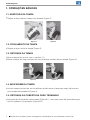
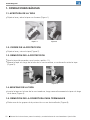
1. OPERAÇÕES BÁSICAS
1.1. ABERTURA DA TAMPA
g
Segure a alça e abra a tampa com firmeza (Figura 1).
1.2. FECHAMENTO DA TAMPA
g
Segure a alça e feche a tampa (Figura 2).
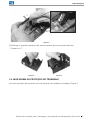
1.3. RETIRADA DA TAMPA
g
Abra a tampa (de acordo com o capítulo 1.1);
g
Mova a tampa ao longo da base da seccionadora e então retire a tampa (Figura 3).
1.4. MONTAGEM DA TAMPA
g
Insira a tampa na base da seccionadora e então mova a tampa ao longo da base da
seccionadora firmemente (Figura 4).
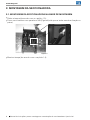
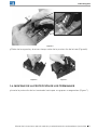
1.5. RETIRADA DA COBERTURA PARA TERMINAIS
g
Na proteção de terminais selecionada (Figura 5) 1, com uma chave de fenda desloque
um dos grampos da proteção (Figura 5) 2;
Figura 1
Figura 2
Figura 3 Figura 4

www.weg.net
Manual de instruções para a montagem e manutenção de seccionadoras tipo fusível 5
g
Desloque o segundo grampo e ao mesmo tempo retire a proteção da base
(Figuras 6 e 7).
Figura 5
1.6. MONTAGEM DA PROTEÇÃO DE TERMINAIS
g
Insira a proteção de terminais na base até que seus grampos engatem (Figura 7).
2
2
1
Figura 6 Figura 7
1
2
1

www.weg.net
Manual de instruções para a montagem e manutenção de seccionadoras tipo fusível6
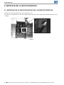
g
Monte a tampa (de acordo com o capítulo 1.4).
Figura 8
2. MONTAGEM DA SECCIONADORA
2.1. MONTAGEM DA SECCIONADORA NA BASE DE MONTAGEM
g
Retire a tampa (de acordo com o capítulo 1.3);
g
Fixe a seccionadora com parafusos M6 (Figura 8) até que se tenha uma boa fixação no
painel;

www.weg.net
Manual de instruções para a montagem e manutenção de seccionadoras tipo fusível 7
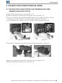
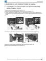
3. FIXAÇÃO DOS CONDUTORES DE SAÍDA
3.1. FIXAÇÃO DOS CONDUTORES COM TERMINAIS DE CABO -
GRAMPO PARAFUSO TIPO M
g
Retire a tampa (de acordo com o capítulo 1.3);
g
Retire as proteções de terminais (de acordo com o capítulo 1.5);
g
Fixe os condutores com parafusos M5 (Figura 12) com torque de 3 Nm ou fixe os
condutores conforme Figura 11 (parafuso M6 com torque de 3 Nm);
g
O kit de parafusos é composto por 12 parafusos M5 e 6 grampos tipo S;
Figura 12
Figura 11
g
Monte as proteções de terminais (de acordo com o capítulo 1.6);
g
Monte a tampa (de acordo com o capítulo 1.4).
g
Destaque os elementos da proteção de terminais apropriados (Figura 13);
Figura 13
1 2

www.weg.net
Manual de instruções para a montagem e manutenção de seccionadoras tipo fusível8
g
Mova um elo-fusível ao longo da tampa até a trava de elos-fusíveis prender (Figura 18);
g
Monte a tampa (de acordo com o capítulo 1.4).
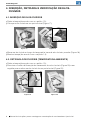
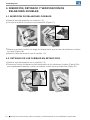
4. INSERÇÃO, RETIRADA E VERIFICAÇÃO DE ELOS-
FUSÍVEIS
4.1. INSERÇÃO DE ELOS-FUSÍVEIS
g
Retire a tampa (de acordo com o capítulo 1.3);
g
Coloque o elo-fusível em um porta-fusível (Figura 17);
4.2. RETIRADA DOS FUSÍVEIS (TEMPERATURA AMBIENTE)
g
Retire a tampa (de acordo com o capítulo 1.3);
g
Pressione o botão de liberação de travamento dos elos-fusíveis (Figura 19) e em
seguida puxe e retire um elo-fusível de um porta-fusível (Figura 20).
Figura 17 Figura 18
Figura 19 Figura 20

www.weg.net
Manual de instruções para a montagem e manutenção de seccionadoras tipo fusível 9
4.4. VERIFICAÇÃO DE CONDIÇÃO DOS ELOS-FUSÍVEIS
g
Mova a corrediça da tampa para a direita para liberar os orifícios de inspeção (Figura 22);
5. LACRE
5.1. TRAVAMENTO DE ORIFÍCIOS DE MEDIÇÃO
g
Para travar mova a corrediça da tampa para a posição superior (Figura 25);
g
Insira o dispositivo de travamento de acordo com a Figura 26;
g
Para destravar mova a corrediça da tampa até a posição central (Figura 27).
Figura 22 Figura 23 Figura 24
g
Verifique a condição dos elos-fusíveis com um detector de tensão (Figura 23);
g
Mova a corrediça da tampa até a posição central (Figura 24).
Figura 25 Figura 26 Figura 27
Figura 21
4.3. RETIRADA DOS FUSÍVEIS (AQUECIDO)
g
Retire a tampa (de acordo com o capítulo 1.3);
g
Pressione o botão de liberação de travamento dos elos-fusíveis (de acordo com o
capítulo 4.2.) (Figura 19, 20);
g
Balance a tampa até desconectar os fusíveis (Figura 21).

www.weg.net
Manual de instruções para a montagem e manutenção de seccionadoras tipo fusível10
5.2. LACRE DA SECCIONADORA
g
Insira o dispositivo de travamento no orifício de acordo com a Figura 28;
g
O dispositivo de travamento deve ficar próximo ao orifício (Figura 29).
Figura 28
Figura 29
6. CONTATOS AUXILIARES
A montagem da chave de contato auxiliar na seccionadora tipo fusível FSW 100 deve ser
realizado pelo fabricante. Não é recomendada a montagem pelo usuário.
7. DESCARTE DO MATERIAL UTILIZADO
As seccionadoras tipo fusível FSW são fabricadas com materiais e tecnologia que não
agridem o meio ambiente.
Normas referentes à proteção do meio ambiente devem ser respeitadas.
O produto utilizado deve ser desmontado e as peças de metal devem ser separadas
das peças plásticas. Peças metálicas sem uso devem ser segregadas em metais não
ferrosos e outros e devem ser sucateadas. Peças plásticas que podem ser recicladas
devem ser enviadas para empresa de reciclagem. Peças plásticas que não podem ser
recicladas devem ser enviadas para empresa especializadas. Embalagens de papelão e
sacos plásticos que são reciclados devem ser enviados para empresas de reciclagem.
Em caso de dúvidas, entre em contato com o fabricante.
8. CONDIÇÕES DE TRANSPORTE E ARMAZENAMENTO
O armazenamento deve ser realizado na embalagem original, em locais secos e limpos
em temperatura superior a -5 ºC e umidade relativa não superior a 80% a temperatura
de +35 ºC. A temperatura mais alta de 40 ºC, a umidade relativa do ar não deve ser
superior a 50%.

www.weg.net
Instruction manual for mounting and service of fuse switch disconnectors 11
CONTENT
ENGLISH
1. BASIC OPERATIONS ............................................................................... 12
1.1. OPENNING OF THE COVER ............................................................ 12
1.2. CLOSING THE COVER ..................................................................... 12
1.3. TAKING OFF THE COVER ................................................................ 12
1.4. MOUNTING THE COVER ................................................................. 12
1.5. TAKING OFF THE SHIELD FOR TERMINALS ................................ 12
1.6. MOUNTING THE SHIELD FOR TERMINALS .................................. 13
2. MOUNTING THE DISCONNECTOR ........................................................14
2.1. MOUNTING THE DISCONNECTOR ON A MOUNTING PLATE ......14
3. FIXING OUTGOING CONDUCTORS ...................................................... 15
3.1. FIXING CONDUCTORS WITH CABLE TERMINAL- BOLT CLAMP
OF M TYPE ....................................................................................... 15
4. INSERTING, TAKING OFF AND CHECKING OF FUSE LINKS .............. 16
4.1. MOUNTING OF FUSE LINKS ........................................................... 16
4.2. TAKING OFF COLD FUSE LINKS .................................................... 16
4.3. TAKING OFF HOT FUSE LINKS .......................................................17
4.4. CHECKING THE CONDITION OF FUSE LINKS ..............................17
5. SEALING ....................................................................................................17
5.1. SEALING OF MEASURING HOLES ..................................................17
5.2. SEALING OF THE DISCONNECTOR .............................................. 18
6. AUXILIARY CONTACT BLOCK ................................................................ 18
7. PROCEEDING WITH THE MATERIAL UTILIZED ................................... 18
8. TRANSPORT AND STORAGE CONDITIONS ......................................... 18

www.weg.net
Instruction manual for mounting and service of fuse switch disconnectors12
1. BASIC OPERATIONS
1.1. OPENNING OF THE COVER
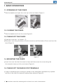
g
Take the handle and open the cover up to firm resistance (Figure 1).
1.2. CLOSING THE COVER
g
Take the handle and close the cover (Figure 2).
1.3. TAKING OFF THE COVER
g
Open the cover (acc. to chapter 1.1);
g
Move the cover along the base of the disconnector and then take off the cover form the
base (Figure 3).
1.4. MOUNTING THE COVER
g
Insert the cover into the disconnector base and then move the cover along the
disconncetor base up to firm resistance (Figure 4).
1.5. TAKING OFF THE SHIELD FOR TERMINALS
g
Using a screwdriver press locking of catches of the shield and simultaneously squeeze
catches of the shield for terminals making them released (Figure 5);
Figure 1
Figure 2
Figure 3 Figure 4

www.weg.net
Instruction manual for mounting and service of fuse switch disconnectors 13
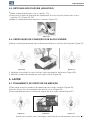
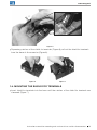
g
Squeezing catches of the shield for terminals (Figure 6) pull out the shield for terminals
form the base of disconnector (Figure 6).
Figure 5
1.6. MOUNTING THE SHIELD FOR TERMINALS
g
Insert shield for terminals into the base until the catches of the shield for terminals are
slammed (Figure 7).
2
2
Figure 6 Figure 7
1
2
1
1

www.weg.net
Instruction manual for mounting and service of fuse switch disconnectors14
2. MOUNTING THE DISCONNECTOR
2.1. MOUNTING THE DISCONNECTOR ON A MOUNTING PLATE
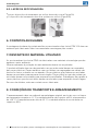
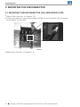
g
Take off the cover (acc. to chapter 1.3);
g
Fix the disconnector to a mounting plate with M6 screws (Figure 8) until you have a
good fixation on the panel;
g
Mount the cover (acc. to chapter 1.4).
Figure 8

www.weg.net
Instruction manual for mounting and service of fuse switch disconnectors 15
3. FIXING OUTGOING CONDUCTORS
3.1. FIXING CONDUCTORS WITH CABLE TERMINAL- BOLT CLAMP OF
M TYPE
g
Take off the cover (acc. to chapter 1.3);
g
Take off the shield for terminals (acc. to chapter 1.5);
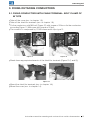
g
Fix the conductors with M5 bolt (Figure 12) with torque of 3 Nm or fix the conductors
according Figure 11 (M6 screw with torque of 3 Nm);
g
The screw kit is compound by 12 M5 screw and 6 clips type S;
Figure 12
Figure 11
g
Mount the shield for terminals (acc. to chapter 1.6);
g
Mount the cover (acc. to chapter 1.4).
g
Break down appropriate elements of the shield for terminals (Figure 13 (1 and 2));
Figure 13
1 2

www.weg.net
Instruction manual for mounting and service of fuse switch disconnectors16
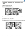
g
Move a fuse link along the cover until the locking of fuse links is slammed (Figure 18);
g
Mount the cover ( acc. to point 1.4).
4. INSERTING, TAKING OFF AND CHECKING OF FUSE
LINKS
4.1. MOUNTING OF FUSE LINKS
g
Take off the cover (acc. to chapter 1.3);
g
Place the fuse link in a fuse holder (Figure 17);
4.2. TAKING OFF COLD FUSE LINKS
g
Take off the cover (acc. to chapter 1.3);
g
Press the release button for locking of fuse links (Figure 19) and then pull out a fuse link
from a fuse holder (Figure 20).
Figure 17 Figure 18
Figure 19 Figure 20

www.weg.net
Instruction manual for mounting and service of fuse switch disconnectors 17
Figure 21
4.3. TAKING OFF HOT FUSE LINKS
g
Take off the cover (acc. to chapter 1.3);
g
Press the release button for locking of fuse links (acc. to chapter 4.2.) (Figure 19, 20);
g
Tilt the cover causing the self pulling out of fuse links from the fuse holders (Figure 21).
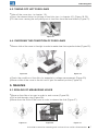
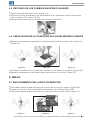
4.4. CHECKING THE CONDITION OF FUSE LINKS
g
Move a slide of the cover to the right in order to make clear the inspection holes (Figure 22);
5. SEALING
5.1. SEALING OF MEASURING HOLES
g
Move up the slide of a cover in order to seal a cover (Figure 25);
g
Pull a seal through a lug (Figure 26);
g
Move down the slide of the cover in order to release the slide (Figure 27).
g
Check the condition of fuse links for example by voltage measurement (Figure 23);
g
Move a slide of the cover to the left until it gets the neutral position (Figure 24).
Figure 22 Figure 23 Figure 24
Figure 25 Figure 26 Figure 27

www.weg.net
Instruction manual for mounting and service of fuse switch disconnectors18
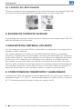
6. AUXILIARY CONTACT BLOCK
The assembly of auxiliary contact block in the Fuse switch-disconnectors FSW 100 it will
be assembled manufacturers.
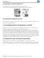
7. PROCEEDING WITH THE MATERIAL UTILIZED
FSW type fuse switch disconnectors are manufactured with the use of materials and
technology which are not harmful to the natural environment.
Obligatory regulations regarding protection of the environment should be respected.
The product utilized should be dismantled and metal parts should be apart from plastic
ones. Useless metal parts should be segregated to non- ferrous metals and others and
they are to be scraped. Plastic parts which can be recycled should be sent to recycling
company. Plastic parts which can not be recycled should be sent to utilization company.
Cardboard packaging and plastic bags which are recycled should be sent to recycling
companies. In case of any doubts please contact with the manufacturer.
8. TRANSPORT AND STORAGE CONDITIONS
Storage should be performed in original packaging, in dry and clean rooms at
temperature higher than -5
o
C and related humidity not higher than 80% at temperature
+35
o
C. At the highest temperature +40
o
C air humidity should not be higher than 50%.
5.2. SEALING OF THE DISCONNECTOR
g
Seal by passing a string through sealing eye (Figure 28);
g
Seal should be tighten the closest to element being sealed (Figure 29).
Figure 28
Figure 29

www.weg.net
Manual de instrucciones para el montaje y mantenimiento de seccionadoras tipo fusible 19
CONTENIDO
ESPAÑOL
1. OPERACIONES BÁSICAS ........................................................................ 20
1.1. APERTURA DE LA TAPA .................................................................. 20
1.2. CIERRE DE LA PROTECCIÓN ........................................................ 20
1.3. REMOCIÓN DE LA PROTECCIÓN .................................................. 20
1.4. MONTAJE DE LA TAPA .................................................................... 20
1.5. REMOCIÓN DE LA COBERTURA PARA TERMINALES ............... 20
1.6. MONTAJE DE LA PROTECCIÓN DE LOS TERMINALES .............. 21
2. MONTAJE DE LA SECCIONADORA ...................................................... 22
2.1. MONTAJE DE LA SECCIONADORA EN LA BASE DE MONTAJE .. 22
3. FIJACIÓN DE LOS CONDUCTORES DE SALIDA ................................. 23
3.1. FIJACIÓN DE LOS CONDUCTORES CON TERMINAL DE
CABLE - GRAPA TORNILLO TIPO M .............................................. 23
4. INSERCIÓN, RETIRADO Y VERIFICACIÓN DE ESLABONES-
FUSIBLES .................................................................................................. 24
4.1. INSERCIÓN DE ESLABONES-FUSIBLES ...................................... 24
4.2. RETIRADO DE LOS FUSIBLES EN ESTADO FRIO ........................ 24
4.3. RETIRADO DE LOS FUSIBLES EN ESTADO CALIENTE .............. 25
4.4. VERIFICACIÓN DE LA CONDICIÓN DE LOS ESLABONES-
FUSIBLES .......................................................................................... 25
5. SELLO ........................................................................................................ 25
5.1. ENCLAVAMIENTO DEL HUECO DE MEDICIÓN ............................ 25
5.2. LACRADO DEL SECCIONADOR .................................................... 26
6. BLOQUE DE CONTACTO AUXILIAR ....................................................... 26
7. DESCARTE DEL MATERIAL UTILIZADO................................................ 26
8. CONDICIONES DE TRANSPORTE Y ALMACENADO ........................... 26

www.weg.net
Manual de instrucciones para el montaje y mantenimiento de seccionadoras tipo fusible
20
1. OPERACIONES BÁSICAS
1.1. APERTURA DE LA TAPA
g
Sujete el asa y abra la tapa con firmeza (Figura 1).
1.2. CIERRE DE LA PROTECCIÓN
g
Sujete el asa y cierre la tapa (Figura 2).
1.3. REMOCIÓN DE LA PROTECCIÓN
g
Abra la tapa (de acuerdo con el punto capítulo 1.1);
g
Mueva la tapa a lo largo de la base de la seccionadora, a continuación retire la tapa
(Figura 3).
1.4. MONTAJE DE LA TAPA
g
Inserte la tapa en la base de la seccionadora, luego mueva firmemente la tapa a lo largo
de la base (Figura 4).
1.5. REMOCIÓN DE LA COBERTURA PARA TERMINALES
g
Retire una de las grapas de la protección con un destornillador (Figura 5);
Figura 1
Figura 2
Figura 3 Figura 4

www.weg.net
Manual de instrucciones para el montaje y mantenimiento de seccionadoras tipo fusible 21
g
Retire de la segunda y al mismo tiempo retire de la proctección de la base (Figura 6).
Figura 5
1.6. MONTAJE DE LA PROTECCIÓN DE LOS TERMINALES
g
Inserte la protección de los terminales hasta que sus grapas se enganchen (Figura 7).
2
2
1
Figura 6 Figura 7
1
2
1

www.weg.net
Manual de instrucciones para el montaje y mantenimiento de seccionadoras tipo fusible
22
Figura 8
2. MONTAJE DE LA SECCIONADORA
2.1. MONTAJE DE LA SECCIONADORA EN LA BASE DE MONTAJE
g
Retire la tapa (de acuerdo con el capítulo 1.3);
g
Fije la seccionadora con tornillos M6 (Figura 8) hasta que tenga una buena fijación en el
panel.

www.weg.net
Manual de instrucciones para el montaje y mantenimiento de seccionadoras tipo fusible 23
3. FIJACIÓN DE LOS CONDUCTORES DE SALIDA
3.1. FIJACIÓN DE LOS CONDUCTORES CON TERMINAL DE CABLE -
GRAPA TORNILLO TIPO M
g
Retire la tapa (de acuerdo con el capítulo 1.3);
g
Retire la protección de terminales (de acordo com el capítulo 1.5);
g
Fije los conductores con M5 (Figura 12) con esfuerzo de torsión 3 Nm o adjuntar los
conductores como se muestra en la Figura 11 (tornillo M6 con esfuerzo de torsión de
3 Nm);
g
El kit se compone de tornillos 12 tornillos M5 y 6 presilla tipo S;
Figura 12
Figura 11
g
Monte las protecciones de terminales (de acuerdo con capítulo 1.6);
g
Monte la tapa (de acuerdo con el capítulo 1.4).
g
Destaque los elementos apropiados de la protección de terminales (Figura 13);
Figura 13
1 2

www.weg.net
Manual de instrucciones para el montaje y mantenimiento de seccionadoras tipo fusible
24
g
Mueva un eslabón-fusible a lo largo de la tapa hasta que la traba de eslabones-fusibles
lo sujete (Figura 18);
g
Monte la tapa (de acuerdo con el capítulo 1.4).
4. INSERCIÓN, RETIRADO Y VERIFICACIÓN DE
ESLABONES-FUSIBLES
4.1. INSERCIÓN DE ESLABONES-FUSIBLES
g
Retire la tapa (de acuerdo con capítulo 1.3);
g
Coloque el eslabón-fusible en un portafusible (Figura 17);
4.2. RETIRADO DE LOS FUSIBLES EN ESTADO FRIO
g
Retire la tapa (de acuerdo con el capítulo 1.3);
g
Presione el botón de liberación de intertrabado de los eslabones-fusibles (Figura 19) e
em seguidamente empuje y retire un eslabón-fusible de un portafusible (Figura 20).
Figura 17 Figura 18
Figura 19 Figura 20

www.weg.net
Manual de instrucciones para el montaje y mantenimiento de seccionadoras tipo fusible 25
4.4. VERIFICACIÓN DE LA CONDICIÓN DE LOS ESLABONES-FUSIBLES
g
Mueva la corredera de la tapa hacia la derecha para liberar los orificios de inspección
(Figura 22);
5. SELLO
5.1. ENCLAVAMIENTO DEL HUECO DE MEDICIÓN
g
Para trabar mueva la tapa de protección móvil para la posición superior (Figura 25);
g
Inserte el dispositivo de enclavamiento de acuerdo con la Figura (Figura 26);
g
Para liberar mueva la tapa de protección móvil hasta la posición central (Figura 27).
g
Verifique la condición de los eslabones-fusibles con un detector de tensión (Figura 23);
g
Mueva la corredera de la tapa hacia abajo hasta cerrar los orificios (Figura 24).
Figura 22 Figura 23 Figura 24
Figura 25 Figura 26 Figura 27
4.3. RETIRADO DE LOS FUSIBLES EN ESTADO CALIENTE
g
Retire la tapa (de acuerdo con el capítulo 1.3);
g
Presione el botón de liberación de intertrabado de los eslabones-fusibles (de acordo
com o capítulo 4.2.) (Figura 19, 20);
g
Mueva la tapa hasta que los fusibles desconecten (Figura 21).
Figura 21

www.weg.net
Manual de instrucciones para el montaje y mantenimiento de seccionadoras tipo fusible
26
5.2. LACRADO DEL SECCIONADOR
g
Inserte el dispositivo de enclavamiento en el hueco de acuerdo con la figura (Figura 28);
g
El dispositivo de enclavamiento debe quedar próximo al hueco (Figura 29).
6. BLOQUE DE CONTACTO AUXILIAR
El ensamblaje del bloque de contacto auxiliar en interruptor-seccionador fusible FSW 100
debe ser realizado por el fabricante.
7. DESCARTE DEL MATERIAL UTILIZADO
Las seccionadores tipo fusible FSW son fabricadas con materiales y tecnología que no
agreden el medio ambiente.
Las normas referentes a la protección del medio ambiente deben ser respetadas.
El producto utilizado debe ser desmontado y las piezas de metal deben ser separadas
de las piezas plásticas. Las piezas metálicas sin uso deben ser segregadas en metales
no ferrosos y otros, debiendo ser clasificadas como chatarra. Las piezas plásticas
que pueden ser recicladas deben ser enviadas a la empresa de reciclaje. Las piezas
plásticas que no pueden ser recicladas deben ser enviadas a empresas especializadas.
Los embalajes de cartón y bolsas plásticas que son reciclados deben ser enviados a
empresas de reciclaje. En caso de dudas, entre en contacto con el fabricante.
8. CONDICIONES DE TRANSPORTE Y ALMACENADO
El almacenado debe ser realizado en el embalaje original, en locales secos y limpios a
temperatura entre -5 ºC y 35 ºC y una humedad relativa no superior a 80%. A más de
40 ºC, la humedad relativa del aire no debe ser superior a 50%.
Figura 28
Figura 29

NOTES

WEG Worldwide Operations
Rev: 04 | Date (m/y): 10/2016
The values shown are subject to change without prior notice.
WEG Group - Automation Business Unit
Jaraguá do Sul - SC - Brazil
Phone: +55 (47) 3276-4000
automacao@weg.net
www.weg.net
ARGENTINA
San Francisco - Cordoba
Phone: +54 3564 421484
info-ar@weg.net
Cordoba - Cordoba
Phone: +54 351 4641366
Buenos Aires
Phone: +54 11 42998000
AUSTRALIA
Scoresby - Victoria
Phone: +61 3 97654600
AUSTRIA
Markt Piesting - Wiener
Neustadt-Land
Phone: +43 2633 4040
watt@wattdrive.com
BELGIUM
Nivelles - Belgium
Phone: +32 67 888420
BRAZIL
Jaraguá do Sul - Santa
Catarina
Phone: +55 47 32764000
CHILE
La Reina - Santiago
Phone: +56 2 27848900
CHINA
Nantong - Jiangsu
Phone: +86 513 85989333
Changzhou – Jiangsu
Phone: +86 519 88067692
COLOMBIA
San Cayetano - Bogota
Phone: +57 1 4160166
ECUADOR
El Batan - Quito
Phone: +593 2 5144339
FRANCE
Saint-Quentin-Fallavier - Isère
Phone: +33 4 74991135
GERMANY
Türnich - Kerpen
Phone: +49 2237 92910
info-de@weg.net
Balingen - Baden-
Württemberg
Phone: +49 7433 90410
info@weg-antriebe.de
GHANA
Accra
Phone: +233 30 2766490
info@zestghana.com.gh
INDIA
Bangalore - Karnataka
Phone: +91 80 41282007
Hosur - Tamil Nadu
Phone: +91 4344 301577
ITALY
Cinisello Balsamo - Milano
Phone: +39 2 61293535
JAPAN
Yokohama - Kanagawa
Phone: +81 45 5503030
MALAYSIA
Shah Alam - Selangor
Phone: +60 3 78591626
info@wattdrive.com.my
MEXICO
Huehuetoca - Mexico
Phone: +52 55 53214275
Tizayuca - Hidalgo
Phone: +52 77 97963790
NETHERLANDS
Oldenzaal - Overijssel
Phone: +31 541 571080
PERU
La Victoria - Lima
Phone: +51 1 2097600
PORTUGAL
Maia - Porto
Phone: +351 22 9477700
RUSSIA and CIS
Saint Petersburg
Phone: +7 812 363 2172
SOUTH AFRICA
Johannesburg
Phone: +27 11 7236000
info@zest.co.za
SPAIN
Coslada - Madrid
Phone: +34 91 6553008
wegiberia@wegiberia.es
SINGAPORE
Singapore
Phone: +65 68589081
Singapore
Phone: +65 68622220
SCANDINAVIA
Mölnlycke - Sweden
Phone: +46 31 888000
UK
Redditch - Worcestershire
Phone: +44 1527 513800
UNITED ARAB EMIRATES
Jebel Ali - Dubai
Phone: +971 4 8130800
USA
Duluth - Georgia
Phone: +1 678 2492000
Minneapolis - Minnesota
Phone: +1 612 3788000
VENEZUELA
Valencia - Carabobo
Phone: +58 241 8210582
For those countries where there is not a WEG own operation, find our local distributor at www.weg.net.
-
 1
1
-
 2
2
-
 3
3
-
 4
4
-
 5
5
-
 6
6
-
 7
7
-
 8
8
-
 9
9
-
 10
10
-
 11
11
-
 12
12
-
 13
13
-
 14
14
-
 15
15
-
 16
16
-
 17
17
-
 18
18
-
 19
19
-
 20
20
-
 21
21
-
 22
22
-
 23
23
-
 24
24
-
 25
25
-
 26
26
-
 27
27
-
 28
28


en otros idiomas
- português: WEG FSW 100 Manual do usuário
Artículos relacionados
-
WEG FSW 250 Manual de usuario
-
-
-
-
-
 Automation Direct Soft-starter SSW07 Manual de usuario
-
-
-
 Automation Direct CFW300 Manual de usuario
-

