LG ES9428 Series Wall Oven Manual de usuario
- Categoría
- Hornos
- Tipo
- Manual de usuario

INSTALLATION MANUAL
WALL OVEN
Read this installation manual thoroughly before installing the
appliance and keep it handy for reference at all times.
ENGLISH
WDES9428*, WSES4728*, WDEP9427*, WSEP4727*, WDEP9423*, WSEP4723*
MFL51224812
Rev.06_020923
www.lg.com
Copyright © 2021-2023 LG Electronics Inc. All Rights Reserved.
en-us_main.book.book Page 1 Thursday, February 9, 2023 3:20 PM

TABLE OF CONTENTS
2
3 IMPORTANT SAFETY
INSTRUCTIONS
3 READ ALL INSTRUCTIONS BEFORE USE
3 Safety Messages
3 WARNING
3 Installation
4 INSTALLATION
4 Before Installing
4 Proper Location and Dimensions
10 Parts / Tools
11 Installing the Oven and Test Run
11 Unpacking and Removing Oven Doors
12 Electrical Requirements
12 Making Electrical Connections
14 Installing Oven and Assembling Oven
Doors and Bottom Decorative Trim
15 Test the Oven Before Use
en-us_main.book.book Page 2 Thursday, February 9, 2023 3:20 PM

3IMPORTANT SAFETY INSTRUCTIONS
ENGLISH
SAVE THESE INSTRUCTIONS
IMPORTANT SAFETY INSTRUCTIONS
READ ALL INSTRUCTIONS BEFORE USE
Safety Messages
Your safety and the safety of others are very important.
We have provided many important safety messages in this manual and on your appliance. Always read and
follow all safety messages.
All safety messages will tell you what the potential hazard is, tell you how to reduce the chance of injury,
and tell you what may happen if the instructions are not followed.
WARNING
WARNING
• To reduce the risk of explosion, fire, death, electric shock, injury or scalding to persons when using this
product, follow basic precautions, including the following:
Installation
• Never allow anyone to climb, sit, stand or hang on the oven door. Injury might result from contact with
hot food or the oven itself.
• Do not line the oven walls, racks, bottom, or any other part of the oven with aluminum foil or any other
material. Doing so will disrupt heat distribution, produce poor baking results and cause permanent
damage to the oven interior (aluminum foil will melt to the interior surface of the oven).
• Do not use aluminum foil or any other material to line the oven bottom. Improper installation of oven
liners may result in a risk of electric shock or fire.
• Make sure your appliance is properly installed and grounded by a qualified installer, according to the
installation instructions. Any adjustment and service should be performed only by qualified installers or
service technicians.
• Be certain that all packing materials are removed from the appliance before operating. Keep plastic,
clothes, paper, and other flammable materials away from parts of the appliance that may become hot.
• The electrical power must be shut off while the electrical connections are being made.
• Improper connection of aluminum house wiring to copper leads can result in an electrical hazard or fire.
Use only connectors designed for joining copper to aluminum and follow the manufacturer’s
recommended procedure closely.
This is the safety alert symbol.
This symbol alerts you to potential hazards that can kill or injure you and others. All safety messages
will follow the safety alert symbol and either the word WARNING or CAUTION.
These words mean:
WARNING
You may be killed or seriously injured if you do not follow instructions.
CAUTION
You may be injured or cause damage to the product if you do not follow instructions.
en-us_main.book.book Page 3 Thursday, February 9, 2023 3:20 PM

4INSTALLATION
INSTALLATION
Before Installing
Proper Location and Dimensions
CAUTION
• The cabinet base platform must be able to
support 190 lbs (86 kg) for single built-in oven,
325 lbs (147 kg) for double built-in oven. If the
cabinet does not have a solid bottom, two braces
or runners must be installed level with the
bottom of the cutout to support the weight of
the appliance. Make sure the base is level and
the front of the cabinet is square. If the cabinet
base is not level, the oven racks will tend to slide
out when opening the door.
• Make sure the cabinets and wall coverings
around the oven can withstand the temperature
(up to 194 ℉ (90 ℃)) generated by the oven.
Discoloration, delamination or melting may
occur.
• Kitchen cabinets in contact with the oven must
be heat resistant up to 194°F (90°C), and fronts
of nearby units up to at least 158°F (70°C).
• DO NOT remove spacers c on the side walls of
the built-in oven. These spacers center the oven
in the space provided.The oven must be
centered to prevent excess heat buildup that
may result in heat damage or fire.
• The information in this manual should be
followed exactly. Failure to do so could result in
fire or electrical shock, causing property
damage, personal injury or death.
• DO NOT put any weight on the oven door. Never
allow anyone to climb, sit, stand or hang on the
oven door. The oven could be tipped and injury
might result from contact with hot food or the
oven itself.
• DO NOT block the oven air exhaust located at
the bottom of the oven. Blocking the exhaust
may cause cabinet damage and product
malfunction.
NOTE
• If marks, blemishes or the cutout opening are
visible above the installed appliance, it may be
necessary to add wood shims under the runners
and front trim until the marks or opening are
covered.
• If the cabinet does not have a front frame and
the sides are less than 3/4” (1.9 cm) thick, shim
both sides equally to establish the cutout width.
• The junction box a must be flush with the
conduit opening b of the cabinet as shown.
• Allow at least a 23” clearance for the door depth
when it is open.
• Do not remove the gliding racks from the base
packing. Gliding racks are attached separately to
the top and bottom of the oven.
en-us_main.book.book Page 4 Thursday, February 9, 2023 3:20 PM

5INSTALLATION
ENGLISH
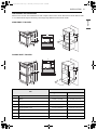
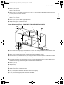
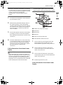
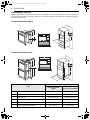
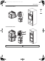
Dimensions and Clearances
Measure the current cutout dimensions and compare them to the cutout dimensions shown below. Little
or no cabinet work may be necessary. The image may differ from the actual model
SINGLE BUILT- IN OVEN
DOUBLE BUILT- IN OVEN
List Dimensions
Single wall oven Double Wall Oven
A Height 29 7/16" (74.7 cm) 52 1/16" (132.3 cm)
B Width 29 3/4" (75.5 cm) 29 3/4" (75.5 cm)
C Depth 23 3/8" (59.3 cm) 23 3/8" (59.3 cm)
D Height (standard installation) 29" (73.6 cm) 51 9/16" (131.0 cm)
E Height (power cord) 27 1/2" (70.0 cm) 50 5/16" (127.7 cm)
F Length (power cord) 60" (152.4 cm) 60" (152.4 cm)
G Width (back) 27 3/8" (695.3 mm) 27 3/8" (695.3 mm)
H Width (standard installation) 28 7/16" (72.2 cm) 28 7/16" (72.2 cm)
J
I
K
N
P
M
O
Q
L
H
G
D
E
F
A
B
C
Q
LN
P
M
JI
K
O
H
G
DE
F
A
B
C
en-us_main.book.book Page 5 Thursday, February 9, 2023 3:20 PM

6INSTALLATION
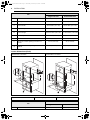
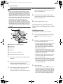
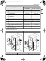
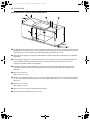
Cutout Dimensions (Flush)
I Cabinet width 30" (76.2 cm) 30" (76.2 cm)
J Overlap of oven 1" (2.5 cm) 1" (2.5 cm)
KCutout width 28 1/2" Min. (72.4 cm)
28 5/8" Max. (72.7 cm)
28 1/2" Min. (72.4 cm)
28 5/8" Max. (72.7 cm)
L Depth of open door 23" (58.4 cm) 23" (58.4 cm)
M Cutout height 29 1/8" Min. (74.0 cm)
29" 3/16" Max. (74.1 cm)
51 13/16” Min. (131.6 cm)
51 15/16” Max. (131.9 cm)
N Cutout depth 24" Min. (61.0 cm) 24" Min. (61.0 cm)
O Cutout location from floor 31" (78.7 cm) 12" (30.5 cm)
PHeight of conduit opening from floor of
cutout
23 1/2" (59.7 cm) 47" (119.4 cm)
QDistance of conduit opening from side of
cabinet
5" (12.7 cm) 5" (12.7 cm)
SINGLE BUILT- IN OVEN DOUBLE BUILT- IN OVEN
a Junction box b Conduit opening c Cleat (Spacer)
List Dimensions
Single wall oven Double Wall Oven
A Cutout width 30" (76.2 cm) 30" (76.2 cm)
List Dimensions
Single wall oven Double Wall Oven
G
E
J
BC
D
A
H
F
I
K
L
K
G
E
J
BC
D
I
A
H
F
L
en-us_main.book.book Page 6 Thursday, February 9, 2023 3:20 PM

7INSTALLATION
ENGLISH
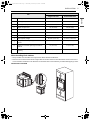
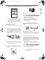
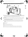
When Installing Flush Cabinet
• The provided cover brackets are only used for flush cabinet installations.
• Remove one screw from the left and right sides as shown. These screw holes will be used to mount the
cover brackets. Install the cover brackets on the sides of the oven with the provided self-tapping screws.
SINGLE BUILT- IN OVEN
B Cleat (spacer) inset from front of cabinet 1 3/8" (3.5 cm) 1 3/8" (3.5 cm)
C Cleat (spacer) width 3/16" (0.5 cm) 3/16" (0.5 cm)
D Cleat (spacer) depth 1" (2.5 cm) 1" (2.5 cm)
E Depth of open door 23" (58.4 cm) 23" (58.4 cm)
F Bottom of cutout from floor 31" (78.7 cm) 12" (30.5 cm)
G Cutout depth 25" (63.5 cm) 25" (63.5 cm)
H Cutout height 29 5/8" (75.2 cm) 52 5/16" (132.9 cm)
I Cleat (spacer) height 28 9/16" (72.6 cm) 51 9/32" (130.3 cm)
JHeight of conduit opening from floor of
cutout
23 1/2" (59.7 cm) 47" (119.4 cm)
KDistance of conduit opening from side of
cabinet
5" (12.7 cm) 5" (12.7 cm)
L Bottom of bottom decorative trim to vent
opening
3/4" (1.9 cm) 3/4" (1.9 cm)
List Dimensions
Single wall oven Double Wall Oven
en-us_main.book.book Page 7 Thursday, February 9, 2023 3:20 PM

8INSTALLATION
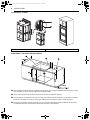
DOUBLE BUILT- IN OVEN
SINGLE BUILT- IN OVEN UNDERCOUNTER
aGas or electric cooktops may be installed over this oven. See cooktop installation instructions for cutout
size. See label on top of oven for approved cooktop models.
b240 V / 208 V junction box location (Junction box may be in adjacent cabinet.)
cGas and electrical connections for 30” (76.2 cm) gas cooktop must be located in an adjacent accessible
location to the right. For a 36” (91.4 cm) gas cooktop, the connections may be made to the left.
dTop and/or side fillers may be necessary if unit is positioned between existing cabinets. Be sure they
are attached securely, because they will anchor the oven in the cabinets.
a Cover Bracket b 4X22 Self-Tapping Screw
en-us_main.book.book Page 8 Thursday, February 9, 2023 3:20 PM

9INSTALLATION
ENGLISH
e29 1/8" (74.0 cm) min.
29 3/16" (74.1 cm) max.
fAllow 11/16" (1.7 cm) overlap on top of oven, 11/16" (1.7 cm) overlap on side edges of cutout and 11/16"
(1.7 cm) overlap on bottom of oven.
g28 1/2" (72.4 cm) min.
28 5/8" (72.7 cm) max.
h23 1/2" (59.7 cm) min. above support platform
i36" (91.4 cm) typical countertop height
Cutout Dimensions (Flush) - SINGLE BUILT- IN OVEN UNDERCOUNTER
aGas or electric cooktops may be installed over this oven. See cooktop installation instructions for cutout
size. See label on top of oven for approved cooktop models.
b240 V / 208 V junction box location (Junction box may be in adjacent cabinet.)
cGas and electrical connections for 30” (76.2 cm) gas cooktop must be located in an adjacent accessible
location to the right. For a 36” (91.4 cm) gas cooktop, the connections may be made to the left.
dTop and/or side fillers may be necessary if unit is positioned between existing cabinets. Be sure they
are attached securely, because they will anchor the oven in the cabinets.
e29 5/8" (75.2 cm)
f30" (76.2 cm)
g23 1/2" (59.7 cm) from the cutout base
h36" (91.3 cm) typical countertop height
i3/4" (1.9 cm) bottom of bottom decorative trim to vent opening
j1 3/8" (3.5 cm) cleat (spacer) inset from front of cabinet
en-us_main.book.book Page 9 Thursday, February 9, 2023 3:20 PM

10 INSTALLATION
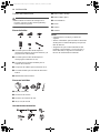
Parts / Tools
WARNING
• Mounting screws must be used. Failure to do so
can result in the oven falling out of the cabinet
and causing serious injury.
Parts Provided
a4X14 6 Wood screws for mounting (4 needed
for installation and 2 extras)
b4X24 6 Wood screws for mounting (for flush
installation)
c4X22 2 Self-tapping screws for cover bracket
d2 Cover brackets for flush installation
e4X10 2 Screws for bottom decorative trim
fBottom decorative trim
Parts Not Provided
aJunction box
bWire nuts
c3/4" Conduit connector
d36" (91 cm) String
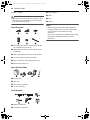
Tools Needed
aPhillips screwdriver
bFlat-blade screwdriver
cTape measure
dPliers
eDrill
fGloves
NOTE
• Observe all governing codes and ordinances.
• Have the installer show you the location of the
circuit breaker or fuse. Mark it for easy
reference.
• Be sure your appliance is installed and grounded
properly by a qualified installer or service
technician.
en-us_main.book.book Page 10 Thursday, February 9, 2023 3:20 PM

11INSTALLATION
ENGLISH
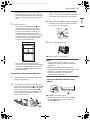
Installing the Oven and Test
Run
Unpacking and Removing Oven
Doors
WARNING
• Keep packing materials out of the reach of
children. Packaging material can be dangerous
for children. There is a risk of suffocation.
• You should use two or more people to move and
install the appliance. (Excessive Weight Hazard)
Failure to do so can result in back or other injury.
• Do not use the door handles to push or pull the
appliance during installation or when moving
the appliance out for cleaning or service. Doing
so can result in serious damage to the door of
the appliance.
• To reduce the risk of burns, do not move this
appliance while it is hot.
NOTE
• To remove any remaining tape or glue, rub the
area briskly with your thumb. Tape or glue
residue can also be easily removed by rubbing a
small amount of liquid dish soap over the
adhesive with your fingers. Wipe with warm
water and dry.
• Do not use sharp instruments, rubbing alcohol,
flammable fluids, or abrasive cleaners to remove
tape or glue. These products can damage the
surface of your appliance.
• Door removal is not a requirement for
installation of the oven, but is an added
convenience.
Unpacking Materials
Remove any packing material from the oven
before installing the oven.
1 Remove all tape from around the oven.
2 Open the oven door and remove the
packaging materials and oven racks inside the
oven.
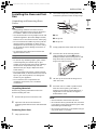
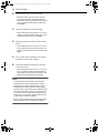
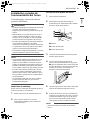
Removing Oven Door
1 Fully open the door.
2 Unlock the hinge locks, rotating them as far
toward the open door frame as they will go.
aSlot
bHinge lock
cHinge arm
3 Firmly grasp both sides of the door at the top.
4 Close the door to the removal position
(approximately five degrees d) which is
halfway between the broil stop position and
fully closed. If the position is correct, the
hinge arms will move freely.
5 Lift door up and out until the hinge arm is
clear of the slot.
6 Place the oven on a table or platform even
with the cutout opening. The table or
platform must support 190 lbs (86 kg) for a
single built-in oven, 325 lbs (147 kg) for a
double built-in oven.
NOTE
• Use two hands to remove the oven door.
• Do not lift the door by the handle. The oven door
is very heavy. Firmly grasp the door by the sides
before lifting it off the hinges.
• Do not lay the oven door on its handle. Doing so
may cause dents or scratches.
en-us_main.book.book Page 11 Thursday, February 9, 2023 3:20 PM

12 INSTALLATION
Electrical Requirements
Ensure that dedicated circuit protection is
prepared as recommended and that the appliance
is grounded properly.
• This wall oven must be electrically grounded in
accordance with local codes or, in their absence,
with the National Electrical Code ANSI/NFPA
No.70- latest edition in United States, or with CSA
Standard C22.1-1982 and C22.2 No.01982 (or
latest edition), Canadian Electrical Code, Part1,
and all local codes and ordinances.
• This wall oven must be supplied with the proper
voltage and frequency, and connected to an
individual, properly grounded branch circuit,
protected by a circuit breaker or fuse. To know
the circuit breaker or fuse required by this
model, see the rating plate to find the wattage
consumption and refer to the table below to get
the circuit breaker or fuse amperage.
WARNING
• DO NOT ground to a gas pipe.
• DO NOT have a fuse in the neutral or grounding
circuit.
• A UL-listed conduit connector must be provided
at the junction box.
• The appliance must be hard wired (direct wired)
into an approved junction box. A plug and
receptacle is not permitted on these products.
• DO NOT shorten the flexible conduit. The
conduit connector must be securely attached to
the junction box and the flexible conduit must be
securely attached to the conduit connector. If
the flexible conduit will not fit within the
connector, do not install the oven until a
connector of the proper size is obtained.
NOTE
• The power leads supplied with the appliance are
UL, CSA recognized for connection to larger
gauge household wiring. The insulation of these
leads is rated at temperatures much higher than
the temperature rating of household wiring. The
current carrying capacity of the conductor is
governed by the wire gauge and the
temperature rating of the insulation around the
wire.
• You will need to purchase an appropriate
conduit connector to complete the connection of
the conduit to the junction box.
Making Electrical Connections
WARNING
• New branch-circuit installations (1996 NEC),
mobile homes, recreational vehicles, or
installations where local codes prohibit
grounding through the neutral conductor
require 4-wire branch-circuit connection.
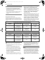
Appliance rating Watts 240 V
Category Power consumption Protection circuit
recommended
Wire gauge
recommended
Single wall oven 6100 W (WSES4728*,
WSEP4727*)
4600 W (WSEP4723*)
30 A 12 AWG
Double wall oven 10200 W (WDES9428*)
10700 W (WDEP9427*)
9200 W (WDEP9423*)
50 A (WDES9428*,
WDEP9427*)
40 A (WDEP9423*)
10 AWG
Appliance rating Watts 208 V
Category Power consumption Protection circuit
recommended
Wire gauge
recommended
Single wall oven 4600 W (WSES4728*,
WSEP4727*)
3500 W (WSEP4723*)
30 A (WSES4728*,
WSEP4727*)
20 A (WSEP4723*)
12 AWG (WSES4728*,
WSEP4727*)
14 AWG (WSEP4723*)
Double wall oven 7700 W (WDES9428*)
8100 W (WDEP9427*)
6900 W (WDEP9423*)
40 A 10 AWG
en-us_main.book.book Page 12 Thursday, February 9, 2023 3:20 PM

13INSTALLATION
ENGLISH
• Improper connection of aluminum house wiring
to copper leads can result in an electrical hazard
or fire. Use only connectors designed for joining
copper to aluminum and follow the
manufacturer’s recommended procedure
closely.
1 Turn off the circuit breaker or remove fuses to
the oven branch circuit.
2 With the oven positioned directly in front of
the cabinet opening, connect the flexible
conduit to the electrical junction box. Position
the conduit in such a manner that it will lie on
top of the oven in a natural loop when the
oven is installed.
3 If local codes permit connection of the frame
grounding conductor to the neutral (white)
wire, follow the instructions for a 3-wire circuit
connection.
4 If used in mobile homes or new construction,
or a recreational vehicle, or local codes do not
permit connection of the frame grounding
conductor to the neutral (white) wire, follow
the instructions for a 4-wire circuit
connection.
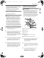
3-Wire Connection from Home Power
Supply
WARNING
• The middle (neutral or ground) wire, which is
white, of a 3-wire power cord or a 3-wire conduit
has to be connected to the middle post of the
main terminal block. The remaining two wires of
the power cord or conduit have to be connected
to the outside posts of the main terminal
connection block. Failure to do so can result in
electrical shock, severe personal injury or death.
aCable from home power supply
bBlack wires
cWhite wires
dRed wires
eGreen (or bare) ground wires
f4-wire flexible conduit from oven
1 Connect the oven ground (green) wire and
neutral (white) wire to the branch circuit
neutral (white or gray) wire, using a wire nut.
2 Connect the oven red wire to the branch
circuit red (L2) wire in accordance with local
codes, using a wire nut.
3 Connect the oven black wire to the branch
circuit black (L1) wire in accordance with local
codes, using a wire nut.
4 Install the junction box cover.
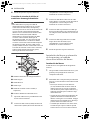
4-Wire Connection from Home Power
Supply
en-us_main.book.book Page 13 Thursday, February 9, 2023 3:20 PM

14 INSTALLATION
WARNING
• Only use a 4-conductor power-supply cord kit
rated 120/240 volts, 50 amperes and marked for
use with ranges with closed-loop connectors or
open spade lugs with upturned ends. The white
middle (neutral) wire of the power cord or 4-wire
conduit has to be connected to the middle post
of the main terminal block. The other two wires
of the power cord or conduit have to be
connected to the outside posts of the main
terminal connection block. The 4th ground wire
(green) must be connected to the frame of the
oven with the ground screw. Failure to do so can
result in electrical shock, severe personal injury
or death.
aCable from home power supply
bBlack wires
cWhite wires
dRed wires
eGreen (or bare) ground wires
f4-wire flexible conduit from oven
1 Separate the oven ground and white wires if
necessary.
2 Connect the oven ground (green) wire to the
branch circuit ground (green) wire in
accordance with local codes, using a wire nut.
3 Connect the oven white wire to the branch
circuit neutral (white or gray) wire in
accordance with local codes, using a wire nut.
4 Connect the oven red wire to the branch
circuit red (L2) wire in accordance with local
codes, using a wire nut.
5 Connect the oven black wire to the branch
circuit black (L1) wire in accordance with local
codes, using a wire nut.
6 Install the junction box cover.
Installing Oven and Assembling
Oven Doors and Bottom Decorative
Trim
Installing the Oven
Install the oven into the cabinet as follows:
1 Use caution when lifting the oven and wear
gloves to protect hands from any sharp
edges.
2 Use two or more people to lift or move the
oven into the cabinet opening.
• Loop (do not tie) a 36” (91 cm) string around
the conduit before the oven is slid into
place. Lay the string over the top of the
oven and use it to keep the conduit from
falling behind the oven.
• Lift the oven into the cabinet cutout using
the oven opening as a grip. Carefully push
against the oven front frame. Do not push
against the outside edges.
• While sliding the oven back, pull the string
so that the conduit lies on the top of the
oven in a natural loop.
• When you are sure the conduit is out of the
way, slide the oven 3/4 of the way back into
the opening. Remove the string by pulling
on one end of the loop.
3 Secure the oven.
• Using the mounting holes a on the oven
side trim as a guide, drill pilot holes for the
screws provided. (For securing the double
wall oven, use a minimum of 4 screws, one
on each side in both the upper and lower
ovens. For securing the single wall oven,
en-us_main.book.book Page 14 Thursday, February 9, 2023 3:20 PM

15INSTALLATION
ENGLISH
use a minimum of 2 screws, one on each
side.)
• Secure the oven to the cabinet with the
screws provided. If the cabinet is particle
board, you must use 3/4” particle board
screws. These may be purchased at any
hardware store.
Assembling Oven Doors
1 Firmly grasp both sides of the door at the top.
2 With the door at the same angle as the
removal position, seat the indentation c of
the hinge arms a into the bottom edge of the
hinge slots b. The notch in the hinge arms
must be fully seated into the bottom edge of
the slots.
3 Open the door fully. If the door will not open
fully, the indentation is not seated correctly in
the bottom edge of the slots.
4 Lock the hinge locks d, rotating them back
toward the slots in the oven frame until they
lock.
5 Close the oven door.
aBottom vent trim
NOTE
• When you install the oven door, be carefull not
to bump the bottom vent trim.
• Keep oven vents unobstructed. Replace the
bottom vent trim if it becomes bent or
deformed. Never block the vent with plastic or
heat-sensitive items.
Assembling the Bottom Decorative
Trim
aBottom decorative trim
• After installing the oven in the cabinet, assemble
bottom decorative trim with 2 screws b (4X10).
Test the Oven Before Use
Each of the functions has been factory checked
before shipping. However, it is suggested that you
verify the operation of the oven once more. Refer
to the owner’s manual and follow the instructions
for the basic check.
• Turn on the power supply. The initial signal
sound is heard and the Clock segment appears
in the display.
NOTE
• Depending on the model, some of the following
functions may not be available.
1 Turn on the power supply. The initial signal
sound will be heard.
en-us_main.book.book Page 15 Thursday, February 9, 2023 3:20 PM

16 INSTALLATION
2 Check the operation of the broil mode.
• When the oven is set to broil, the upper
element in the oven should become red.
After a few minutes, partially open the oven
door. You should feel heat from the oven.
Press Stop.
3 Check the operation of the bake mode.
• After setting the oven to 350 ℉ / 177 ℃ for
baking, the temperature of the oven in the
display should increase. Press Stop.
4 Check the operation of the convection bake
mode.
• After setting the oven to 350 ℉ / 177 ℃ for
convection baking, the fan inside the oven
should come on with the door closed. Press
Stop.
5 Turn on and off the oven light to check that
the lights are in normal condition.
6 Check the operation of the burner for each
convection mode.
• After setting the oven to 350 ℉ / 177 ℃ for
each convection mode, the back element
should light up and the fan inside the oven
should come on with the door closed.
NOTE
• A small amount of smoke and odor may be
noticeable during the initial break-in period.
• If the oven does not operate properly or an F-,
followed by a number, appears in the display,
see the owner’s manual for the troubleshooting
list. The list includes common occurrences that
are not the result of defective workmanship or
materials in this product. If the problem occurs
continuously, contact the dealer.
• Refer to the warranty in the owner’s manual for
the LG toll-free service number and address.
en-us_main.book.book Page 16 Thursday, February 9, 2023 3:20 PM

MANUAL DE INSTALACIÓN
HORNO DE PARED
Lea detenidamente el manual de instalación antes de instalar el
aparato y consérvelo a mano en todo momento para su
referencia.
ESPAÑOL
WDES9428*, WSES4728*, WDEP9427*, WSEP4727*, WDEP9423*, WSEP4723*
www.lg.com
Copyright © 2021-2023 LG Electronics Inc. Todos los derechos reservados
es-us_main.book.book Page 1 Thursday, February 9, 2023 3:32 PM

ÍNDICE
2
3 INSTRUCCIONES IMPORTANTES
DE SEGURIDAD
3 LEA TODAS LAS INSTRUCCIONES ANTES DE
UTILIZAR
3 Mensajes de Seguridad
3 ADVERTENCIA
3 Instalación
5INSTALACIÓN
5 Antes de la Instalación
5 Dimensiones y ubicación adecuadas
12 Piezas/Herramientas
13 Instalación y prueba de funcionamiento del
horno
13 Desembalaje y extracción de las puertas
del horno
14 Requisitos eléctricos
15 Conexiones eléctricas
16 Instalación del horno y colocación de las
puertas y el reborde decorativo inferior del
horno
18 Pruebe el horno antes de usarlo
es-us_main.book.book Page 2 Thursday, February 9, 2023 3:32 PM

3INSTRUCCIONES IMPORTANTES DE SEGURIDAD
ESPAÑOL
INSTRUCCIONES IMPORTANTES DE SEGURIDAD
LEA TODAS LAS INSTRUCCIONES ANTES DE UTILIZAR
Mensajes de Seguridad
Su seguridad y la de los demás son muy importantes.
Tanto en este manual como en el equipo, hemos proporcionado muchos mensajes de seguridad
importantes. Siempre debe leer y respetar todos los mensajes de seguridad.
Todos los mensajes de seguridad le indicarán cuál es el riesgo potencial, le indicarán cómo reducir la
probabilidad de lesiones y le proporcionarán información sobre qué podría suceder si no se siguen las
instrucciones.
ADVERTENCIA
ADVERTENCIA
• Para reducir el riesgo de explosiones, incendios, descargas eléctricas, quemaduras, lesiones o muerte de
las personas al usar este producto, siga las precauciones básicas, incluidas las siguientes:
Instalación
• Nunca permita que nadie se suba, pare o cuelgue de la puerta del horno. Podría sufrir lesiones por el
contacto con la comida caliente o el horno mismo.
• No recubra las paredes del horno, los estantes, el fondo ni ninguna otra parte del horno con papel de
aluminio ni ningún otro material. Esto altera la distribución de calor, produce resultados de horneado
deficientes y causa daños permanentes al interior del horno (el papel de aluminio se fundirá en la
superficie interior del horno).
• No utilice papel de aluminio ni ningún otro material para revestir la base del horno. La instalación
inadecuada de los revestimientos del horno podría causar riesgo de descarga eléctrica o incendio.
• Haga que un instalador calificado instale y conecte a tierra su electrodoméstico de manera apropiada,
de acuerdo con las instrucciones de instalación. Cualquier ajuste y servicio deben realizarlo
exclusivamente instaladores de hornos o técnicos de servicio calificados.
• Asegúrese de retirar todos los materiales del embalaje antes de la puesta en funcionamiento. Mantenga
el plástico, telas, papel y otros materiales inflamables lejos de las piezas del electrodoméstico que se
podrían calentar.
• Se debe cortar el suministro de electricidad mientras se llevan a cabo las conexiones eléctricas.
Este es el símbolo de alerta de seguridad.
Este símbolo le advierte de posibles peligros que pueden matarlos o lastimarlos a usted y a otros.
Todos los mensajes de seguridad seguirán el símbolo de alerta de seguridad y la palabra
ADVERTENCIA o PRECAUCIÓN.
Estos términos significan lo siguiente:
ADVERTENCIA
Podría sufrir lesiones graves o la muerte si no sigue las instrucciones.
PRECAUCIÓN
Puede resultar lesionado o causar daño al producto si no sigue las instrucciones.
es-us_main.book.book Page 3 Thursday, February 9, 2023 3:32 PM

4INSTRUCCIONES IMPORTANTES DE SEGURIDAD
GUARDE ESTAS INSTRUCCIONES
• La conexión incorrecta del cableado doméstico de aluminio a los cables de cobre puede provocar
descargas eléctricas o un incendio. Utilice únicamente conectores diseñados para unir cobre con
aluminio y siga al pie de la letra el procedimiento recomendado por el fabricante.
es-us_main.book.book Page 4 Thursday, February 9, 2023 3:32 PM

5INSTALACIÓN
ESPAÑOL
INSTALACIÓN
Antes de la Instalación
Dimensiones y ubicación
adecuadas
PRECAUCIÓN
• La plataforma base del gabinete debe poder
soportar 190 lb (86 kg) para un horno
empotrado simple y 325 lb (147 kg) para un
horno empotrado doble. Si el gabinete no
cuenta con un fondo sólido, deben instalarse
dos travesaños o guías nivelados con la parte
inferior del corte para sostener el peso del
electrodoméstico. Asegúrese de que la base se
encuentre nivelada y que el frente del gabinete
esté derecho. Si la base del gabinete no está
nivelada, los estantes del horno tenderán a
deslizarse hacia afuera cuando se abra la puerta.
• Asegúrese de que los gabinetes y los
revestimientos de las paredes ubicados
alrededor del horno puedan resistir la
temperatura (de hasta 194 °F [90 °C]) generada
por el horno. Puede producirse decoloración,
delaminación o derretimiento.
• Los gabinetes de la cocina en contacto con el
horno deben ser resistentes al calor hasta 194 ºF
(90 ºC) y los frentes de las unidades cercanas de
hasta al menos 158 ºF (70 ºC).
• NO quite los espaciadores c de las paredes
laterales del horno empotrado. Estos
espaciadores centran el horno en el espacio
provisto. El horno debe centrarse para evitar una
acumulación excesiva de calor que puede
provocar daños o un incendio.
• La información en este manual se debe seguir
exactamente. Si no se hace, podría tener como
resultado incendio o descarga eléctrica, causar
daños a la propiedad, lesiones personales o la
muerte.
• NUNCA coloque peso sobre la puerta del horno.
Nunca permita que nadie se suba, siente, pare o
cuelgue de la puerta del horno. El horno se
podría inclinar y podría sufrir lesiones por el
contacto con la comida caliente o el horno
mismo.
• NO bloquee la salida del aire del horno, ubicada
en la parte inferior del horno. Si bloquea la
salida, puede causar daños en el gabinete y mal
funcionamiento del producto.
NOTA
• Si quedaran a la vista marcas, imperfecciones o
una abertura sobre el electrodoméstico
instalado, puede ser necesario agregar cuñas de
madera bajo las guías y el reborde frontal hasta
cubrir dichas marcas o abertura.
• Si el gabinete no cuenta con un marco frontal y
los lados tienen un grosor menor a 3/4” (1.9 cm),
coloque cuñas uniformemente sobre ambos
lados para establecer el ancho de la abertura.
• La caja de conexiones a debe estar alineada con
la abertura del conducto b del gabinete, como
se muestra.
• Permita al menos un espaciado de 23" para la
profundidad de la puerta cuando se abre.
• No extraiga los estantes deslizantes del
embalaje de base. Los estantes deslizantes
vienen instalados aparte de las partes
superiores e inferiores del horno.
es-us_main.book.book Page 5 Thursday, February 9, 2023 3:32 PM

6INSTALACIÓN
Dimensiones y espacios
Mida las dimensiones actuales de la abertura y compárelas con las dimensiones de corte que se muestran
a continuación. Puede ser necesario realizar poco o nada de trabajo en los gabinetes. La imagen puede ser
distinta al modelo real.
HORNO EMPOTRADO SIMPLE
HORNO EMPOTRADO DOBLE
Lista
Dimensiones
Horno con pared
simple Horno con pared doble
A Alto 29 7/16" (74.7 cm) 52 1/16" (132.3 cm)
B Ancho 29 3/4" (75.5 cm) 29 3/4" (75.5 cm)
C Profundidad 23 3/8" (59.3 cm) 23 3/8" (59.3 cm)
D Alto (instalación estándar) 29” (73.6 cm) 51 9/16" (131.0 cm)
E Alto (cable de alimentación) 27 1/2" (70.0 cm) 50 5/16" (127.7 cm)
F Largo (cable de alimentación) 60” (152.4 cm) 60” (152.4 cm)
J
I
K
N
P
M
O
Q
L
H
G
D
E
F
A
B
C
Q
LN
P
M
JI
K
O
H
G
DE
F
A
B
C
es-us_main.book.book Page 6 Thursday, February 9, 2023 3:32 PM

7INSTALACIÓN
ESPAÑOL
Dimensiones de corte (al ras)
G Ancho (posterior) 27 3/8" (695.3 mm) 27 3/8" (695.3 mm)
H Ancho (instalación estándar) 28 7/16" (72.2 cm) 28 7/16" (72.2 cm)
I Ancho del gabinete 30” (76.2 cm) 30” (76.2 cm)
J Superposición del horno 1” (2.5 cm) 1” (2.5 cm)
KAncho del corte Mín. 28 1/2” (72.4 cm)
Máx. 28 5/8” (72.7 cm)
Mín. 28 1/2” (72.4 cm)
Máx. 28 5/8” (72.7 cm)
L Profundidad de la puerta abierta 23” (58.4 cm) 23” (58.4 cm)
M Alto del corte Mín. 29 1/8” (74.0 cm)
Máx. 29 3/16” (74.1 cm)
Mín. 51 13/16” (131.6 cm)
Máx. 51 15/16” (131.9 cm)
N Profundidad del corte Mín. 24” (61.0 cm) Mín. 24” (61.0 cm)
O Ubicación del corte respecto del piso 31” (78.7 cm) 12” (30.5 cm)
PAlto de la abertura del conducto desde el
piso del corte
23 1/2" (59.7 cm) 47” (119.4 cm)
QDistancia de la abertura del conducto desde
el lateral del gabinete
5” (12.7 cm) 5” (12.7 cm)
HORNO EMPOTRADO SIMPLE HORNO EMPOTRADO DOBLE
a Caja de conexiones b Abertura del conducto c Abrazadera (espaciador)
Lista
Dimensiones
Horno con pared
simple Horno con pared doble
G
E
J
BC
D
A
H
F
I
K
L
K
G
E
J
BC
D
I
A
H
F
L
es-us_main.book.book Page 7 Thursday, February 9, 2023 3:32 PM

8INSTALACIÓN
Cuando instala el gabinete al ras
• Los soportes provistos de la cubierta solo se utilizan para las instalaciones del gabinete al ras.
• Quite un tornillo desde los lados izquierdos y derechos como se muestra. Estos orificios de tornillos se
utilizarán para instalar los soportes de la cubierta. Instale los soportes de la cubierta en los costados del
horno con los tornillos autorroscantes proporcionados.
Lista
Dimensiones
Horno con pared
simple Horno con pared doble
A Ancho del corte 30” (76.2 cm) 30” (76.2 cm)
BInserción de la abrazadera (espaciador)
desde la parte frontal del gabinete
1 3/8" (3.5 cm) 1 3/8" (3.5 cm)
C Ancho de la abrazadera (espaciador) 3/16" (0.5 cm) 3/16" (0.5 cm)
D Profundidad de la abrazadera (espaciador) 1” (2.5 cm) 1” (2.5 cm)
E Profundidad de la puerta abierta 23” (58.4 cm) 23” (58.4 cm)
F Parte inferior del corte desde el piso 31” (78.7 cm) 12” (30.5 cm)
G Profundidad del corte 25” (63.5 cm) 25” (63.5 cm)
H Alto del corte 29 5/8" (75.2 cm) 52 5/16" (132.9 cm)
I Alto de la abrazadera (espaciador) 28 9/16" (72.6 cm) 51 9/32" (130.3 cm)
JAlto de la abertura del conducto desde el
piso del corte
23 1/2" (59.7 cm) 47” (119.4 cm)
KDistancia de la abertura del conducto desde
el lateral del gabinete
5” (12.7 cm) 5” (12.7 cm)
L Parte inferior del reborde decorativo
inferior a la abertura de ventilación
3/4" (1.9 cm) 3/4" (1.9 cm)
es-us_main.book.book Page 8 Thursday, February 9, 2023 3:32 PM

9INSTALACIÓN
ESPAÑOL
HORNO EMPOTRADO SIMPLE
HORNO EMPOTRADO DOBLE
a Soporte de la cubierta b Tornillo autoroscante de 4X22
es-us_main.book.book Page 9 Thursday, February 9, 2023 3:32 PM

10 INSTALACIÓN
BAJO MESADA DEL HORNO EMPOTRADO SIMPLE
aLas placas de cocción eléctricas o a gas se pueden instalar sobre este horno. Consulte las instrucciones
de instalación de la placa de cocción para obtener el tamaño del corte. Consulte la etiqueta de la parte
superior del horno para obtener los modelos aprobados de la placa de cocción.
bUbicación de la caja de conexiones de 240 V/208 V (la caja de conexiones puede estar en un gabinete
adyacente).
cLas conexiones eléctricas y a gas para la placa de cocción a gas de 30" (76.2 cm) se debe ubicar en un
lugar accesible y adyacente a la derecha. Para una placa de cocción a gas de 36" (91.4 cm), las
conexiones se deben realizar a la izquierda.
dSe pueden necesitar rellenos laterales y superiores si la unidad está posicionada entre gabinetes
existentes. Asegúrese de que estén sujetos de manera segura, porque sujetarán el horno en los
gabinetes.
eMín. 29 1/8” (74.0 cm)
Máx. 29 3/16” (74.1 cm)
fPermita una superposición de 11/16" (1.7 cm) en la parte superior del horno, una superposición de 11/
16" (1.7 cm) en los bordes laterales del corte y una superposición de 11/16" (1.7 cm) en la parte inferior
del horno.
gMín. 28 1/2” (72.4 cm)
Máx. 28 5/8” (72.7 cm)
hMín. 23 1/2” (59.7 cm) sobre la plataforma de soporte
iAltura de la encimera típica de 36" (91.4 cm)
es-us_main.book.book Page 10 Thursday, February 9, 2023 3:32 PM

11INSTALACIÓN
ESPAÑOL
Dimensiones de corte (al ras) - BAJO MESADA DEL HORNO EMPOTRADO SIMPLE
aLas placas de cocción eléctricas o a gas se pueden instalar sobre este horno. Consulte las instrucciones
de instalación de la placa de cocción para obtener el tamaño del corte. Consulte la etiqueta de la parte
superior del horno para obtener los modelos aprobados de la placa de cocción.
bUbicación de la caja de conexiones de 240 V/208 V (la caja de conexiones puede estar en un gabinete
adyacente).
cLas conexiones eléctricas y a gas para la placa de cocción a gas de 30" (76.2 cm) se debe ubicar en un
lugar accesible y adyacente a la derecha. Para una placa de cocción a gas de 36" (91.4 cm), las
conexiones se deben realizar a la izquierda.
dSe pueden necesitar rellenos laterales y superiores si la unidad está posicionada entre gabinetes
existentes. Asegúrese de que estén sujetos de manera segura, porque sujetarán el horno en los
gabinetes.
e29 5/8" (75.2 cm)
f30” (76.2 cm)
g23 1/2" (59.7 cm) desde la base del corte
hAltura de la encimera típica de 36" (91.3 cm)
iParte inferior de 3/4" (1.9 cm) del reborde decorativo inferior a la abertura de ventilación
j1 3/8" (3.5 cm) Inserción de la abrazadera (espaciador) desde la parte frontal del gabinete
es-us_main.book.book Page 11 Thursday, February 9, 2023 3:32 PM

12 INSTALACIÓN
Piezas/Herramientas
ADVERTENCIA
• Deben utilizarse tornillos de montaje. De lo
contrario, el horno podría caer del gabinete y
ocasionar lesiones graves.
Piezas incluidas
a6 tornillos para madera de 4X14 para el
montaje (se requieren 4 para la instalación y se
proporcionan 2 adicionales)
b6 tornillos para madera de 4X24 para el
montaje (para instalación al ras)
c2 tornillos autorroscantes de 4X22 para el
soporte de la cubierta
d2 soportes de cubierta para instalación al ras
e2 tornillos de 4X10 para el reborde decorativo
inferior
fReborde decorativo inferior
Piezas no incluidas
aCaja de conexiones
bConectores de torsión
cConector de conducto de 3/4”
d36” (91 cm) de cuerda
Herramientas necesarias
aDestornillador Phillips
bDestornillador plano
cCinta medidora
dPinzas
eTaladro
fGuantes
NOTA
• Cumpla todos los códigos y ordenanzas
vigentes.
• Solicite al instalador que le muestre la ubicación
del disyuntor o fusible. Márquelo para que sea
fácil de detectar.
• Asegúrese de que su electrodoméstico esté
instalado correctamente y con la conexión a
tierra adecuada, a cargo de un instalador o
técnico de mantenimiento calificado.
es-us_main.book.book Page 12 Thursday, February 9, 2023 3:32 PM

13INSTALACIÓN
ESPAÑOL
Instalación y prueba de
funcionamiento del horno
Desembalaje y extracción de las
puertas del horno
ADVERTENCIA
• No deje los materiales de empaque al alcance de
los niños. Estos materiales pueden ser
peligrosos para los niños y presentan riesgo de
asfixia.
• Debe haber dos o más personas para mover e
instalar el electrodoméstico. (Peligro de peso
excesivo). Si no se cumple con esto, se pueden
producir lesiones en la espalda o de otro tipo.
• No utilice las manijas de la puerta para empujar
o tirar del electrodoméstico durante la
instalación ni al moverlo para tareas de limpieza
o reparaciones. Si lo hace, podría causar daños
graves a la puerta del electrodoméstico.
• Para reducir el riesgo de quemaduras, no mueva
el electrodoméstico mientras esté caliente.
NOTA
• Para remover cualquier cinta adhesiva o goma
restante frote enérgicamente el área con su
pulgar. La cinta adhesiva o residuos de goma
pueden ser fácilmente removidos frotando una
pequeña cantidad de jabón líquido para platos
con sus dedos. Limpie con agua caliente y seque.
• No utilice instrumentos puntiagudos, alcohol
para frotar, fluidos inflamables o limpiadores
abrasivos para remover cinta adhesiva o goma.
Estos productos pueden dañar la superficie del
electrodoméstico.
• La eliminación de la puerta no es un requisito
para la instalación del horno, pero es una
conveniencia agregada.
Materiales de embalaje
Retire todos los materiales de embalaje del horno
antes de proceder a su instalación.
1 Retire toda la cinta de alrededor del horno.
2 Abra la puerta del horno y retire los
materiales de embalaje y los estantes del
interior del horno.
Extracción de la puerta del horno
1 Abra la puerta totalmente.
2 Desbloquee las trabas de las bisagras
haciéndolas girar alejándolas todo lo posible
del marco de la puerta abierta.
aRanura
bTraba de la bisagra
cBrazo de la bisagra
3 Tome firmemente ambos lados de la puerta
desde la parte superior.
4 Cierre la puerta hasta la posición de
extracción (aproximadamente cinco grados
d) que es a mitad de camino entre la posición
de tope del asador y totalmente cerrada. Si la
posición es correcta, los brazos de las
bisagras se moverán libremente.
5 Levante la puerta y tire hacia afuera hasta que
el brazo de la bisagra salga de la ranura.
6 Coloque el horno en una mesa o plataforma
uniforme con la abertura del corte. La mesa o
la plataforma deben soportar 190 lb (86 kg)
para un horno empotrado simple y 325 lb
(147 kg) para un horno empotrado doble.
NOTA
• Use ambas manos para quitar la puerta del
horno.
es-us_main.book.book Page 13 Thursday, February 9, 2023 3:32 PM

14 INSTALACIÓN
NOTA
• No levante la puerta tomándola de la manija. La
puerta del horno es muy pesada. Sujétela
firmemente de los costados antes de levantarla y
liberarla de las bisagras.
• No apoye la puerta del horno sobre la manija. Si
lo hace, pueden producirse abolladuras o
rayones.
Requisitos eléctricos
Asegúrese de que la protección de los circuitos
exclusiva se prepare como se recomienda y de que
el electrodoméstico esté correctamente conectado
a tierra.
• Este horno de pared debe tener una conexión
eléctrica a tierra en cumplimiento con los
códigos locales o, si estos no existieran, de
acuerdo con el Código Eléctrico Nacional, ANSI/
NFPA N.º 70- última edición en los Estados
Unidos, o con la Norma CSA C22.1-1982 y C22.2
N.º 01982 (o última edición), Código Eléctrico
Canadiense, Parte 1, y todos los códigos y
ordenanzas locales.
• Este horno de pared se debe proporcionar con el
voltaje y la frecuencia adecuados, y debe estar
conectado a un circuito derivado correctamente
conectado a tierra e individual, protegido por un
disyuntor o fusible. Para saber si este modelo
necesita el disyuntor o el fusible, consulte la
placa de clasificación para encontrar el consumo
de vataje y la tabla a continuación para obtener
el amperaje del fusible o el disyuntor.
ADVERTENCIA
• NO conecte a tierra con una tubería de gas.
• NO coloque un fusible en el circuito central o de
conexión a tierra.
• La caja de conexiones debe contar con un
conector de conductos homologado por UL.
• El electrodoméstico debe contar con cableado
de conexión permanente (cableado directo) a
una caja de conexiones aprobada. En estos
productos, no se permite la conexión del tipo
"enchufe y receptáculo".
• NO acorte el conducto flexible. El conector de
conductos debe quedar bien sujeto a la caja de
conexiones y el conducto flexible debe quedar
bien sujeto al conector de conductos. Si el
conducto flexible no entra dentro del conector,
no instale el horno hasta obtener un conector
del tamaño adecuado.
NOTA
• Los cables de alimentación que se suministran
con este electrodoméstico están reconocidos
por UL y CSA para conexiones con cableados
domésticos de calibres mayores. La aislación de
estos cables está clasificada a temperaturas
mucho más elevadas que la clasificación del
cableado doméstico. La capacidad de transmitir
240 V de vatios de clasificación del electrodoméstico
Categoría Consumo de energía Circuito de protección
recomendado
Calibre de cable
recomendado
Horno con pared simple 6100 W (WSES4728*,
WSEP4727*)
4600 W (WSEP4723*)
30 A 12 AWG
Horno con pared doble 10200 W (WDES9428*)
10700 W (WDEP9427*)
9200 W (WDEP9423*)
50 A (WDES9428*,
WDEP9427*)
40 A (WDEP9423*)
10 AWG
208 V de vatios de clasificación del electrodoméstico
Categoría Consumo de energía Circuito de protección
recomendado
Calibre de cable
recomendado
Horno con pared simple 4600 W (WSES4728*,
WSEP4727*)
3500 W (WSEP4723*)
30 A (WSES4728*,
WSEP4727*)
20 A (WSEP4723*)
12 AWG (WSES4728*,
WSEP4727*)
14 AWG (WSEP4723*)
Horno con pared doble 7700 W (WDES9428*)
8100 W (WDEP9427*)
6900 W (WDEP9423*)
40 A 10 AWG
es-us_main.book.book Page 14 Thursday, February 9, 2023 3:32 PM

15INSTALACIÓN
ESPAÑOL
corriente del conductor está determinada por el
calibre del cable y la clasificación de temperatura
de la aislación alrededor del cable.
• Debe adquirir un conector de conductos
adecuado para completar la conexión del
conducto a la caja de conexiones.
Conexiones eléctricas
ADVERTENCIA
• Las instalaciones nuevas de circuito derivado
(1996 NEC), las casas móviles, los vehículos
recreativos o las instalaciones en las que los
códigos locales prohíben la conexión a tierra a
través de un conductor neutral requieren una
conexión de circuito derivado de 4 hilos.
• La conexión incorrecta del cableado doméstico
de aluminio a los cables de cobre puede
provocar descargas eléctricas o un incendio.
Utilice únicamente conectores diseñados para
unir cobre con aluminio y siga al pie de la letra el
procedimiento recomendado por el fabricante.
1 Apague el disyuntor o quite los fusibles del
circuito derivado del horno.
2 Con el horno ubicado directamente frente a la
abertura del gabinete, conecte el conducto
flexible a la caja de conexiones eléctricas.
Coloque el conducto de manera tal que quede
con un lazo natural sobre la parte superior del
horno cuando este se instale.
3 Si los códigos locales permiten la conexión del
conductor a tierra desde el marco al cable
neutral (blanco), siga las instrucciones de
conexión para un circuito de 3 hilos.
4 Si se utiliza en casas móviles, construcciones
nuevas o un vehículo recreativo, o si los
códigos locales no permiten la conexión del
conductor a tierra desde el marco al cable
neutral (blanco), siga las instrucciones de
conexión para un circuito de 4 hilos.
Conexión de circuito de 3 hilos al
suministro de energía doméstico
ADVERTENCIA
• El hilo del medio (neutro o tierra), que es blanco,
de un cable de alimentación de 3 hilos o un
conducto de 3 hilos se debe conectar al poste
medio del bloque de terminales principal. Los
dos hilos restantes del cable de alimentación o
del conducto se deben conectar a los postes
exteriores del bloque de terminales principal. De
lo contrario, podría causar lesiones personales
graves, descargas eléctricas o la muerte.
aCable del suministro de energía doméstico
bCables negros
cCables blancos
dCables rojos
eCables de conexión a tierra verdes (o
expuestos)
fConducto flexible de 4 hilos del horno
1 Conecte el cable a tierra (verde) del horno y el
cable neutral (blanco) al cable neutral del
circuito derivado (blanco o gris) con un
conector de torsión.
2 Conecte el cable rojo del horno al cable rojo
del circuito derivado (L2) en cumplimiento con
los códigos locales, utilizando un conector de
torsión.
3 Conecte el cable negro del horno al cable
negro del circuito derivado (L1) en
cumplimiento con los códigos locales,
utilizando un conector de torsión.
es-us_main.book.book Page 15 Thursday, February 9, 2023 3:32 PM

16 INSTALACIÓN
4 Instale la tapa de la caja de conexiones.
Conexión de circuito de 4 hilos al
suministro de energía doméstico
ADVERTENCIA
• Solo debe utilizar un juego de cable de
alimentación de 4 conductores con un valor
nominal de 120/240 voltios, 50 amperios y
marcado para uso en cocinas de conectores de
circuito cerrado o terminales de horquilla
abiertos con los extremos hacia arriba. El hilo
blanco del medio (neutro) del cable de
alimentación o conducto de 4 hilos se debe
conectar al borne medio del bloque de
terminales principal. Los otros dos hilos del
cable de alimentación o conducto se deben
conectar a los bornes exteriores del bloque de
terminales principal. El cuarto cable a tierra
(verde) se debe conectar al marco del horno con
el tornillo de conexión a tierra. De lo contrario,
podría causar lesiones personales graves,
descargas eléctricas o la muerte.
aCable del suministro de energía doméstico
bCables negros
cCables blancos
dCables rojos
eCables de conexión a tierra verdes (o
expuestos)
fConducto flexible de 4 hilos del horno
1 Separe el cable a tierra y el cable blanco del
horno si fuera necesario.
2 Conecte el cable a tierra (verde) del horno al
cable a tierra (verde) del circuito derivado en
cumplimiento con los códigos locales,
utilizando un conector de torsión.
3 Conecte el cable blanco del horno al cable
neutro (blanco o gris) del circuito derivado en
cumplimiento con los códigos locales,
utilizando un conector de torsión.
4 Conecte el cable rojo del horno al cable rojo
del circuito derivado (L2) en cumplimiento con
los códigos locales, utilizando un conector de
torsión.
5 Conecte el cable negro del horno al cable
negro del circuito derivado (L1) en
cumplimiento con los códigos locales,
utilizando un conector de torsión.
6 Instale la tapa de la caja de conexiones.
Instalación del horno y colocación
de las puertas y el reborde
decorativo inferior del horno
Instalación del horno
Instale el horno en el gabinete de la siguiente
manera:
1 Tenga cuidado cuando levante el horno y use
guantes para protegerse las manos de
cualquier borde filoso.
2 Debe haber dos o más personas para levantar
el horno o colocarlo dentro de la abertura del
gabinete.
• Enlace (no amarre) una cuerda de 36”
(91 cm) alrededor del conducto antes de
deslizar el horno en su lugar. Coloque la
cuerda sobre la parte superior del horno y
úsela para impedir que el conducto caiga
detrás del horno.
• Levante el horno dentro de la abertura del
gabinete utilizando la cavidad del horno
abierto como agarre. Con cuidado, empuje
desde el marco frontal del horno. No haga
presión sobre los bordes externos.
• A medida que desliza el horno hacia atrás,
tire del lazo para que el conducto quede
sobre el horno con una curvatura natural.
es-us_main.book.book Page 16 Thursday, February 9, 2023 3:32 PM

17INSTALACIÓN
ESPAÑOL
• Cuando esté seguro de que el conducto no
obstruya el paso, deslice el horno 3/4 del
recorrido hacia atrás dentro de la abertura.
Quite la cuerda tirando de un extremo del
lazo.
3 Asegure el horno.
• Usando los orificios de montaje a del
reborde lateral del horno como guía,
perfore orificios piloto para los tornillos
provistos. (Para asegurar el horno con
paredes dobles, utilice un mínimo de
4 tornillos, uno en cada lado de los hornos
superior e inferior. Para asegurar el horno
con pared simple, utilice un mínimo de
2 tornillos, uno de cada lado).
• Asegure el horno al gabinete con los
tornillos provistos. Si el gabinete es de placa
de partículas, debe utilizar tornillos de 3/4”
para dicho material. Puede adquirirlos en
cualquier ferretería.
Colocación de las puertas del horno
1 Tome firmemente ambos lados de la puerta
desde la parte superior.
2 Con la puerta en el mismo ángulo que en la
posición de remoción, apoye la hendidura c
de los brazos de las bisagras a en el borde
inferior de las ranuras de las bisagras b. Las
muescas de los brazos de las bisagras deben
estar totalmente apoyadas en el borde
inferior de las ranuras.
3 Abra totalmente la puerta. Si la puerta no se
abre por completo, la hendidura no está bien
apoyada en el borde inferior de las ranuras.
4 Bloquee las trabas d girándolas nuevamente
hacia las ranuras del marco del horno hasta
que se cierren correctamente.
5 Cierre la puerta del horno.
aReborde inferior de ventilación
NOTA
• Cuando instale la puerta del horno, tenga
cuidado de no golpear el reborde inferior de
ventilación.
• Mantenga las ventilaciones del horno sin
obstrucciones. Reemplace el reborde inferior de
ventilación si se dobla o deforma. Nunca
bloquee la ventilación con elementos
termosensibles o de plástico.
Colocación del reborde decorativo
inferior
aReborde decorativo inferior
• Después de instalar el horno en el gabinete,
coloque el reborde decorativo inferior con
2 tornillos b (4X10).
es-us_main.book.book Page 17 Thursday, February 9, 2023 3:32 PM

18 INSTALACIÓN
Pruebe el horno antes de usarlo
Cada una de las funciones se comprobó en la
fábrica antes del despacho. Sin embargo, le
sugerimos que verifique el funcionamiento del
horno una vez más. Consulte el Manual del
Propietario y siga las instrucciones para la
verificación básica.
• Encienda el suministro de alimentación. Suena la
señal inicial y el segmento del reloj aparece en la
pantalla.
NOTA
• Según el modelo, algunas de las funciones
pueden no estar disponibles.
1 Encienda el suministro de alimentación.
Sonará la señal inicial.
2 Verifique el funcionamiento del modo Broil
(Asar).
• Configure el horno en la función asar; el
elemento calentador superior del horno
debe volverse rojo. Pasados unos minutos,
abra parcialmente la puerta del horno.
Debe sentir el calor que emana del interior.
Presione Stop (Detener).
3 Verifique el funcionamiento del modo Bake
(Hornear).
• Después de configurar el horno a 350 ºF/
177 ºC para hornear, la temperatura del
horno en la pantalla debe aumentar.
Presione Stop (Detener).
4 Verifique el funcionamiento del modo
Convection Bake (Hornear por convección).
• Luego de configurar el horno en 350 ℉/
177 ℃ para hornear por convección, se
debe poner en marcha el ventilador dentro
del horno, con la puerta cerrada. Presione
Stop (Detener).
5 Encienda y apague la luz del horno para
comprobar que las luces se encuentran en
condiciones.
6 Verifique el funcionamiento del quemador
para cada modo de convección.
• Después de configurar el horno en 350 ℉/
177 °C para cada modo de convección, el
elemento calentador posterior debe
iluminarse y se debe poner en marcha el
ventilador dentro del horno con la puerta
cerrada.
NOTA
• Es posible que perciba un poco de humo u olor
durante los primeros usos del electrodoméstico.
• Si el horno no funciona correctamente o aparece
F- junto con un número en la pantalla, consulte
la lista de Resolución de problemas en el Manual
del propietario. La lista incluye situaciones
comunes que no se deben a defectos en los
materiales o la fabricación del producto. Si el
problema se produce de manera continua,
comuníquese con el vendedor.
• Consulte la garantía, en el Manual del
propietario, para obtener el número telefónico
gratuito del servicio de LG y su dirección.
es-us_main.book.book Page 18 Thursday, February 9, 2023 3:32 PM

19Memorándum
es-us_main.book.book Page 19 Thursday, February 9, 2023 3:32 PM

LG Customer Information Center
Register your product Online!
www.lg.com
For inquiries or comments,
visit www.lg.com or call:
1-800-243-0000
U.S.A.
1-888-542-2623
CANADA
es-us_main.book.book Page 19 Thursday, February 9, 2023 3:32 PM
-
 1
1
-
 2
2
-
 3
3
-
 4
4
-
 5
5
-
 6
6
-
 7
7
-
 8
8
-
 9
9
-
 10
10
-
 11
11
-
 12
12
-
 13
13
-
 14
14
-
 15
15
-
 16
16
-
 17
17
-
 18
18
-
 19
19
-
 20
20
-
 21
21
-
 22
22
-
 23
23
-
 24
24
-
 25
25
-
 26
26
-
 27
27
-
 28
28
-
 29
29
-
 30
30
-
 31
31
-
 32
32
-
 33
33
-
 34
34
-
 35
35
-
 36
36


LG ES9428 Series Wall Oven Manual de usuario
- Categoría
- Hornos
- Tipo
- Manual de usuario
en otros idiomas
Artículos relacionados
Otros documentos
-
Signature Kitchen Suite SKSDV3002S Guía de instalación
-
Yes LSIS6338FE El manual del propietario
-
-
-
-
-
-
-
GE JT3800SHSS Guía de instalación
-
GE Profile PT9800SHSS Guía de instalación