Mastergrip 540139 El manual del propietario
- Categoría
- Rociador de pintura
- Tipo
- El manual del propietario

1431 VIA PLATA
LONG BEACH, CA 90810-1462
© Copyright 2006, Alltrade Tools LLC Rev.1
www.alltradetools.com
Model / Modèlo
#540139
TOUCH UP SPRAY GUN
PISTOLA ROCIADORA PARA RETOQUE
CAREFULLY READ THROUGH THE ENTIRE OWNER’S MANUAL BEFORE OPERATING YOUR SPRAY GUN SET.
KEEP MANUAL WITH IMPORTANT RECORDS FOR SAFETY INSTRUCTIONS, AND OPERATING PROCEDURES.
Please retain these instructions for future reference.
ANTES DE OPERAR EL JUEGO DE PISTOLA ROCIADORA LEA CUIDADOSAMENTE EL MANUAL
DEL PROPIETARIO. CONSERVE EL MANUAL CON SU DOCUMENTACIÓN IMPORTANTE PARA TENER
A MANO LAS INSTRUCCIONES Y PROCEDIMIENTOS DE OPERACIÓN.
Conserve estas instrucciones como referencia para el futuro.

HALOGENATED HYDROCARBON SOLVENTS. For example: Methylene is not chemically compatible with
the aluminum that might be used in many system components. The chemical reaction caused by these
solvents reacting with aluminum can become violent and lead to an equipment explosion. Guns with
stainless steel fluid passages can be used with these solvents. However aluminum is widely used in
other spray application equipment such as material pumps and cups. Make sure they can also be used
safely with these solvents. Read the label or data sheet for the material you intend to spray. If in doubt
as to whether or not a coating or cleaning material is compatible, contact your material supplier.
Spray materials may be harmful if inhaled, or if there is contact with the skin. Adequate exhaust must
be provided to keep the air free of accumulations of toxic materials. Use a mask or respirator whenever
there is a chance of inhaling sprayed materials. The mask must be compatible with the material being
sprayed and its concentration.
SPECIFICATIONS
Fluid Tip Size: 1.5 mm Diameter
Air Inlet: 1/4" (6,35mm) NPS
Air Consumption: 4 CFM (40 PSI)
Capacity of Cup: 7 fl. oz. (207 cc)
Maximum Pressure: 50 PSI (344,5 kPa)
3
PERSONAL HAZARD WARNINGS
During cleaning and flushing, solvents can be forcefully expelled from fluid and air passages. Some
solvents can cause eye injury. Be sure user and bystanders in the area are wearing impact resistant
eye and face protection. Even small projectiles can injure eyes and cause blindness.
Air under pressure can cause severe injury. Always shut off air supply, drain hose of air pressure and
disconnect tool from air supply when not in use, before changing accessories or when making repairs.
Never direct air at yourself or anyone else. Whipping hoses can cause serious injury. Always check for
damaged or loose hoses and fittings. Never use quick-change couplings at tool. They add weight and
could fail due to vibration. Instead, add a hose whip and connect coupling between air supply and hose
whip, between hose whip and leader hose whip, or between hose whip and leader hose. DO NOT EXCEED
MAXIMUM AIR PRESSURE OF 70 PSI. Always use tool a safe distance from other people in work area.
Maintain tools with care. Keep tools clean and oiled for best and safest performance. Follow instructions
for lubricating and changing accessories. Wiping or cleaning rags and other flammable waste materials
must be placed in a tightly closed metal container and disposed of later in the proper fashion.
Do not wear loose or ill-fitting clothing. Remove watches and rings. Do not overreach. Keep proper footing
and balance at all times. Slipping, tripping and falling can be a major cause of serious injury or death. Be
aware of excess hose left on the walking or work surface. Do not abuse hoses or connectors. Never carry
tool by the hose or yank it to disconnect from power supply. Keep hoses from heat, oil and sharp edges.
Check hoses for weak or worn condition before each use, making certain that all connections are secure.
High sound levels can cause permanent hearing loss. Protect yourself from noise. Noise levels vary with
work surface. Wear ear protectors. When possible secure work with clamps or vise so both hands are
free to operate tool.
Repetitive work motions, awkward positions and exposure vibration can be harmful to hands and
arms. Avoid inhaling dust or handling debris from work processes, which can be harmful to your health.
Operators and maintenance personnel must be physically able to handle the bulk, weight and power of
the tool. This tool is not intended for using in explosive atmospheres and is not insulated for contact with
electric power sources. Solvent and coatings can be highly flammable or combustible especially when
sprayed. Adequate exhaust must be provided to keep air free of accumulations of flammable vapors.
Smoking must never be allowed in the spray area. Fire extinguishing equipment must be present in the
spray area. Never spray near sources of ignition such as pilot lights, welders, etc.
• FAILURE TO HEED ALL WARNINGS COULD RESULT IN SEVERE PERSONAL OR BYSTANDER INJURY,
EVEN DEATH.
• ONLY USE TOOLS FOR PURPOSE THEY ARE INTENDED FOR.
• YOU MUST WEAR PROTECTIVE EYEWEAR AND SUITABLE RESPIRATORY PROTECTION (OSHA
APPROVED) WHILE SPRAYING OR CLEANING THIS GUN OR ITS ATTACHMENTS.
• NEVER AIM SPRAY GUN AT PEOPLE. SOLVENTS AND THINNERS CAN CAUSE INJURY.
• DO NOT EXCEED RATED OPERATING PRESSURE.
• CAUTION: POTENTIAL FLAMMABILITY OF SPRAYED PAINT, AND AVOID SPRAYING NEAR FLAMES
OR SPARKS.
• USE PAINT MASK/RESPIRATOR WHILE OPERATING PRODUCT.
• USE PRODUCT ONLY IN WELL-VENTILATED AREAS.
• WEAR EAR PROTECTORS.
• HALOGENATED HYDROCARBON SOLVENTS. FOR EXAMPLE: METHYLENE IS NOT CHEMICALLY
COMPATIBLE WITH THE ALUMINUM THAT MIGHT BE USED IN MANY SYSTEM COMPONENTS.
2
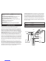
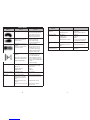
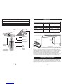
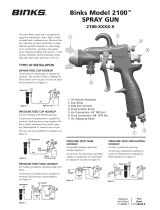
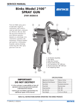
FIGURE 1
Air Nozzle
Air Cap
Container Lock
Container
Spray Pattern
Adjustment Knob
Trigger Handle
Fluid Control
Knob
External Needle Pack
Adjustment (Packing Nut)

SPRAY GUN HANDLING
Your new spray gun is exceptionally rugged in construction and is built to stand up under hard continuous
use. However, like any other fine precision instrument, its most efficient operation depends on knowledge
of its construction, operation, and maintenance. Properly handled and cared for, it will produce beautiful,
uniform finishing results long after other spray guns have worn out.
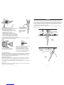
FLUID CONTROL KNOB:
Turn right to decrease flow and left to increase.
1. If a fluid pressure tank is used, the amount
of fluid can also be controlled by regulating
the pressure on the tank.
2. As width of spray is increased, more material
must be allowed to pass through the gun to
obtain the same coverage on the increased
area.
3. The direction of the fan spray, either horizontal
or vertical, is obtained by turning the air nozzle
to the desired position, then tightening the
retainer ring.
As width of spray gun is increased, more material must be allowed to pass through the gun to obtain
same coverage on the increased area.
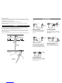
SPRAYING
In normal use, the nozzle wings are horizontal as shown here.
This provides a vertical fan-shaped pattern which gives maximum,
even, material coverage as the gun is moved back and forth parallel
to the surface being finished.
SIPHON SPRAYING
Set atomization pressure at approximately 40 PSI for lacquer and 50 PSI for enamel. Try spray.
If spray is too fine, then decrease the air pressure or open fluid control screw. If the spray is
too thick, then close the fluid control screw. Regulate the pattern width and repeat adjustment
of spray as needed.
5
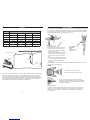
AIR SUPPLY
Never mount oil and water extractor on or near the air compressor. During compression, air temperature
is greatly increased. As the air cools down to room temperature, moisture condenses in the air line, on
its way to the spray supply system where the compressed air temperature is lowest. Drain air lines
properly. Pitch all air lines back towards the compressor so that condensed moisture will flow back into
the air receiver where it can be drained off. Each low point in an air line acts as a water trap. Such
points should be fitted with an easily accessible drain. See diagram above.
4
AIR FLOW LENGTH OF PIPE
CFM 50 ft. [15,24m] 100 ft. [30,48m] 150 ft. [45,72m] 200 ft. [60,96m]
10 [17 m3/h] 1/2" [12,7mm] 3/4" [19mm] 3/4" [19mm] —
20 [34 m3/h] 3/4" [19mm] 3/4" [19mm] 3/4" [19mm] 3/4" [19mm]
30 [51 m3/h] 3/4" [19mm] 3/4" [19mm] 1" [2,5cm] 1" [2,5cm]
40 [68 m3/h] 1" [2,5cm] 1" [2,5cm] 1" [2,5cm] 1" [2,5cm]
50 [85 m3/h] 1" [2,5cm] 1" [2,5cm] 1" [2,5cm] 1" [2,5cm]
70 [119 m3/h] 1" [2,5cm] 1" [2,5cm] 1-1/4" [3,2cm] 1-1/4" [3,2cm]
The spray pattern of the gun is variable
from round to flat with all patterns in between.
SPRAY PATTERN
ADJUSTMENT
KNOB:
Turn right for round
and left for fan.
25 ft. (7,62 meters) OR MORE
Oil and Water Extractor should be at least 25 ft. (7,62 meters) from the compressor, farther if possible.
Tilt pipe back toward air receiver.
Install drain at
each low point
Drain
Drain
Oil and water
extractor
Compressor Unit

SIPHON FEED CUP HOOKUP
Air pressure for atomization is regulated at
extractor. Amount of fluid is adjusted by fluid
control screw on gun, paint viscosity and
air pressure.
PRESSURE FEED CUP HOOKUP
Air pressure for atomization is regulated at
extractor. Fluid pressure is regulated at cup
regulator. For heavy fluids and internal mix
nozzle spraying, fluid adjusted control screw on
gun, pressure cup also available less regulator.
PRESSURE FEED TANK HOOKUP
For portable painting operations
(Double regulator) Air pressure for atomization
and fluid supply is regulated by two individual
air regulators on tank.
PRESSURE FEED TANK HOOKUP
For medium production spraying
(Single regulator) Air pressure for atomization is
regulated at extractor. Fluid pressure is regulated
at tank regulator.
PRESSURE FEED CIRCULATING HOOKUP
For heavy production spraying.
Air pressure atomization regulated at extractor.
Fluid pressure is regulated at fluid regulator.
TYPES OF INSTALLATION
7
PRESSURE SPRAYING
After selecting correct size fluid, set fluid pressure for the desired flow. Open atomization air and test
spray. If spray is too fine, then reduce air pressure. If spray is too coarse, then raise air pressure. Adjust
pattern width and repeat adjustment of spray.
Keeping fluid control screw in open position will reduce fluid needle wear.
NOTE: To reduce overspray and obtain maximum efficiency, always spray with the lowest possible
atomization air pressure.
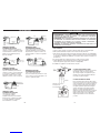
OPERATION
Proper handling of the gun is essential for obtaining a good finish. The gun should be held at right
angle to the surface being covered, moving parallel with the surface. For precise control of the gun
and material, the trigger should be released before the end of the stroke.
Hold the gun from 6 to 12 inches (15,24cm to 30,48cm) away from the surface depending on material
and atomizing pressure. For a uniform finish, lap each stroke over the preceding stroke, making sure
the spray is smooth and wet.
Using the lowest possible atomizing air pressure will reduce over-spray and provide maximum efficiency.
Start
stroke End of
stroke
Pull
trigger Release
trigger
RIGHT
6 to 12 inches
(15,24cm to 30,48cm) Coating should be even
and wet when spraying
TRAVEL OF GUN
Coating will be light
at this point Coating will be heavy
at this point
WRONG
6
Air Inlet Air
Air
Air
Air
Air
Air Supply
Air Hose
Fluid
Fluid
Regulator
Fluid
Fluid
Fluid
Fluid Fluid
Extractor
Extractor
Main Line
Outlet
Pressure Tank
Pressure Tank
Pressure Cup
Siphon Cup
Cup Regulator
Oil and Water
Extractor
Oil and Water
Extractor

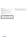
CLEANING AND MAINTENANCE
SPRAY GUN
1. Submerge the front end of the gun in solvent just until the fluid connection is covered.
2. Paint that has built up on the gun should be removed using a bristle brush and solvent.
3. Never submerge all of the spray gun in solvent. This will dissolve the lubricant in the leather
packing and on wear surfaces, causing them to dry out and resulting in difficult operation and
faster wear. Air passages in the gun will become clogged with dirty solvent.
4. Using a rag moistened with solvent, wipe down the outside of the gun.
5. Oil gun daily. Use a drop of lightweight machine oil on:
A. External Needle Pack Adjustment (Packing Nut)
See FIGURE 1 on page 3 for location of above point.
WHEN USED WITH SIPHON CUP
A compatible thinner or solvent should be
siphoned through gun by inserting tube in
open container of that liquid. Trigger gun
repeatedly to flush passageway thoroughly
and to clean tip of needle.
WHEN USED WITH PRESSURE TANK
Shut off air supply to tank and release pressure
on tank. Open vent and loosen air nozzle. Hold
a piece of cloth over the air nozzle and squeeze
trigger. Air will back up through fluid nozzle,
and force fluid out of hose into tank. Next, put
enough thinner into tank to wash hose and gun
thoroughly. Spray thinner through the gun until
it is clean. Attach fluid hose to air line and blow
it out thoroughly to remove all traces of materials
and dry hose.
AIR PRESSURE
Oil and water extractor is important.
Achieving a fine spray finish without the use of a good oil and water extractor is virtually impossible.
The extractor eliminates blistering and spotting by keeping air free of oil and water and gives precise
air pressure control at the gun.
AIR NOZZLE, FLUID NOZZLE, AND NEEDLE ASSEMBLY
1. All nozzles and needles are precision made and should be handled with care.
2. Except as described in #5, do not make any alterations to the gun.
3. To clean nozzles, soak them in solvent to dissolve any dried material. Afterwards, blow the
nozzles clean with air.
4. Do not probe any of the holes in the nozzles with metal instruments. If probing is necessary,
use only a tool that is softer than brass.
5. Adjust the fluid needle valve so when gun is triggered, air flow occurs before fluid flow.
SERVICE
• Tool service must be performed only by qualified repair personnel. Service or maintenance performed
by unqualified personnel could result in a risk of injury.
• When servicing a tool, use only identical replacement parts. Follow instructions in the MAINTENANCE
section of this manual. Use of unauthorized parts or failure to follow Maintenance Instructions may
create a risk of electrical shock or injury.
98
DO NOT USE LUBRICANTS CONTAINING SILICONE.
SILICONE MAY CAUSE DEFECTS IN THE FINISH APPLICATION.
ALL PARTS ON A SPRAY GUN SHOULD BE SCREWED IN BY HAND AT FIRST.
THIS WILL AVOID THE POSSIBILITY OF CROSS THREADING THE PARTS. IF THE PARTS
CANNOT BE TURNED BY HAND EASILY, MAKE SURE YOU HAVE THE CORRECT PARTS,
UNSCREW, REALIGN, AND TRY AGAIN. NEVER USE UNDUE FORCE IN MATING PARTS.
• RESPONSIBILITY. IT SHALL BE THE TOOL OWNER'S RESPONSIBILITY TO ASSURE THAT TOOLS ARE
MAINTAINED IN A SAFE OPERATING CONDITION. IF TOOLS ARE DAMAGED, REMOVE FROM SERVICE
IMMEDIATELY.
• REPAIRS. TOOLS SHALL BE DISCONNECTED FROM THEIR COMPRESSED AIR SUPPLY BEFORE
REPAIR IS ATTEMPTED. REPAIRS SHALL BE CONSISTENT WITH MANUFACTURER'S RECOMMENDED
PROCEDURES. PLEASE REFER TO CLEANING AND MAINTENANCE OR TROUBLESHOOTING SECTIONS.
• REPLACEMENT. TOOLS, HOSES AND FITTINGS SHALL BE REPLACED IF UNSUITABLE FOR SAFE
OPERATION.
Thinner
Keep thinner level
before packing

10 11
SPRAY PATTERN
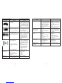
CONDITION PROBLEM SOLUTION
Fluid leakage from
packing nut
a) Packing nut loose.
b) Packing worn or dry.
a) Tighten, but not so tight as to
grip needle.
b) Replace packing or lubricate.
Dripping from fluid tip a) Dry packing.
b) Sluggish needle.
c) Tight packing nut.
d) Worn fluid nozzle or needle.
a) Lubricate.
b) Lubricate.
c) Adjust.
d) For pressure feed, replace with
new fluid nozzle and needle.
Thin, sandy, and coarse
finish
a) Gun held too far from surface.
b) Atomization pressure set too
high.
a) Move gun closer to surface.
b) Adjust atomization pressure.
Thick, dimpled finish
resembling orange peel
Gun held too close to surface. Move gun further away
from surface.
SPRAY PATTERN
CONDITION PROBLEM SOLUTION
One side of nozzle wing is clogged. Soak nozzle in solvent to loosen
clogs, then blow air through until
clean. To clean orifices use a
toothpick. Never try and detach
dried material with sharp tool.
a) Loose air nozzle.
b) Material around outside of air
nozzle has dried.
a) Trigger air nozzle.
b) Take off air nozzle and
wipe off fluid tip, using
rag moistened with thinner.
a) Atomization air pressure is set
too high.
b) Trying to spray a thin material
in too wide a pattern.
a) Reduce air pressure.
b) Increase material control by
turning fluid. Control screw
to left, while reducing spray
width by turning spray width
adjustment screw to right.
Spitting
a) Packing around needle valve is
dried out.
b) Fluid nozzle loosely installed or
dirt between nozzle and body.
c) Needle sealing damaged.
a) Back up knurled nut and put
a few drops of machine oil
on packing. Retighten nut.
b) Take off fluid nozzle. Clean rear
of nozzle and seat in gun body.
Replace nozzle and bring in tight
to body.
c) Replace #4 sealing.
Improper spray pattern a) Gun improperly adjusted.
b) Dirty air cap.
c) Fluid tip obstructed.
d) Sluggish needle.
a) Readjust gun.
Follow instructions carefully.
b) Clean air cap.
c) Clean.
d) Lubricate.
Unable to get round spray Fan adjustment screw
not seating properly.
Clean or replace.
Will not spray a) No air pressure at gun.
b) Fluid pressure too low with
internal mix cap and pressure
tank.
c) Fluid control screw not open
enough.
d) Fluid too heavy for suction feed.
a) Check air supply and air lines.
b) Increase fluid pressure at tank.
c) Open fluid control screw.
d) Thin material or change to
pressure feed.
TROUBLESHOOTING

13
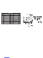
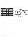
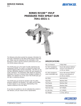
ITEM NO. DESCRIPTION QTY. ITEM NO. DESCRIPTION QTY.
1Air Nozzle 1 11 Air Inlet Pipe 1
2Fluid Nozzle 1 12 Fluid Connection Valves 1
3Screw Trigger 1 13 Spring 1
4Trigger 1 14 Fluid Control Knob 1
5Gun Body 1 15 Packing Material 1
6Washer 1 16 Packing Nut 1
7Valve Seat 1 17 Spray Control Assembly 1
8Valve 1 18 Complete Lid Assembly 1
9Spring 1 19 Container Gasket 1
10 0-Ring 1 20 Container 1
PARTS LIST 691160
12
1
2
5
14
15 16
17
18 13
12
1110987
6
12-1
17-117-217-317-4
12-2 12-3
19
20
3
4

15
Los niveles de sonido altos pueden causar pérdida auditiva permanente. Protéjase del ruido. Los niveles
de ruido varían según la superficie de trabajo. Use protectores para los oídos. Cuando sea posible
afiance el trabajo con abrazaderas o una prensa para poder operar la máquina con ambas manos.
Los movimientos repetitivos durante el trabajo, las posiciones incómodas y la exposición a la vibración
pueden ser perjudiciales para las manos y los brazos. Evite inhalar polvo o manipular desechos de los
procesos de trabajo ya que pueden ser perjudiciales para su salud. Los operadores y el personal de
mantenimiento deben estar en buena condición física para manipular el volumen, peso y potencia
de la herramienta. Esta herramienta no está diseñada para usarse en atmósferas explosivas ni está
aislada contra fuentes de suministro eléctrico. Los disolventes y revestimientos pueden ser sumamente
inflamables o combustibles, especialmente al rociarlos. Proporcione un escape adecuado para mantener
el aire libre de acumulaciones de emanaciones inflamables. Nuca permita que fumen en la zona de
rociado. Mantenga equipos extintores de incendios en la zona de rociado. Nunca rocíe cerca de fuentes
de encendido tales como luces piloto, soldadoras, etc.
DISOLVENTES DE HIDROCARBUROS HALOGENADOS. Por ejemplo: El metileno no es químicamente
compatible con el aluminio que podría estar presente en muchos componentes del sistema. Al
reaccionar conel aluminio, el efecto químico producido por estos disolventes puede tornarse violento y
causar la explosión del equipo. Estos disolventes pueden usarse en pistolas con pasajes de líquido de
acero inoxidable. Sin embargo, el aluminio se usa ampliamente en otros equipos rociadores tales como
bombas y recipientes de materiales. Cerciórese de que estos equipos puedan usarse en forma segura
con dichos disolventes. Lea la etiqueta o la ficha técnica del material que va a rociar. Si tiene dudas
sobre la compatibilidad de un revestimiento o material de limpieza, comuníquese con el distribuidor
del material.
Puede que los materiales rociados sean dañinos si se inhalan, o si entran en contacto con la piel.
Proporcione un escape adecuado para mantener el aire sin acumulaciones de materiales tóxicos.
Use una mascarilla o respirador cuando exista la posibilidad de inhalar materiales rociados. La
mascarilla debe ser compatible con el material rociado y su concentración.
14
ADVERTENCIAS SOBRE PELIGROS PERSONALES
Es posible que durante la limpieza y lavado a presión, los disolventes salgan fuertemente expelidos
desde los pasajes de líquido y aire. Algunos disolventes pueden causar lesiones oculares. Cerciórese de
que el usuario y las personas en las inmediaciones usen protección ocular y facial resistente contra
impactos. Incluso los proyectiles pequeños pueden causar lesiones oculares y ceguera.
El aire a presión puede causar lesiones graves. Siempre apague el suministro de aire, purgue la presión
neumática y desconecte la herramienta del suministro de aire cuando no use la unidad, antes de
cambiar accesorios o cuando efectúe reparaciones. Nunca dirija el aire hacia usted mismo ni contra otra
persona. Las mangueras en movimiento descontrolado pueden causar lesiones graves. Siempre revise
por si hay mangueras y conexiones dañadas o sueltas. Nunca use acopladores de cambio rápido en la
herramienta, pues agregan peso y podrían fallar debido a la vibración. En cambio, agregue una conexión
flexible y empalme el acoplamiento entre el suministro de aire y la conexión, entre la conexión y la
conexión flexible guía o entre la conexión y la manguera guía. NO EXCEDA LA PRESIÓN NEUMÁTICA
MÁXIMA DE 70 LB/PULG2.Siempre use la herramienta a una distancia segura de otras personas en
el área de trabajo. Mantenga las herramientas con cuidado. Mantenga las herramientas limpias y
lubricadas para obtener un rendimiento mejor y más seguro. Siga las instrucciones para lubricar y
cambiar accesorios. Los trapos o paños de limpieza así como otros materiales de desecho inflamables
deben colocarse en un recipiente metálico firmemente cerrado y desecharse correctamente.
No use ropa suelta ni muy holgada. Quítese los relojes y anillos. No intente llegar donde no alcanza.
Mantenga su posición vertical y equilibrio en todo momento. Los resbalones, tropiezos y caídas pueden
ser grandes causantes de lesiones graves o letales. Tenga cuidado con la manguera sobrante que puede
haber quedado en el suelo o en la superficie de trabajo. No use indebidamente las mangueras ni los
conectores. Nunca transporte la herramienta por la manguera ni le dé tirones para desconectarla del
suministro eléctrico. Mantenga las mangueras lejos del calor, aceite y bordes filosos. Revise si las
mangueras están estropeadas o desgastadas antes de usarlas, y cerciórese de que todas las
conexiones estén firmes.
• EL NO ACATAR TODAS LAS ADVERTENCIAS PODRÍA CAUSAR LESIONES PERSONALES INCLUSO
LETALES TANTO AL USUARIO COMO A LAS PERSONAS EN LAS INMEDIACIONES.
• USE LAS HERRAMIENTAS SÓLO PARA LOS PROPÓSITOS PARA LOS CUALES ESTÁN DISEÑADAS.
• DEBERÁ USAR PROTECCIÓN OCULAR Y RESPIRATORIA (APROBADAS POR OSHA) MIENTRAS ROCÍA
O LIMPIA ESTA PISTOLA O SUS ACCESORIOS.
• NUNCA APUNTE A LAS PERSONAS CON LA PISTOLA. LOS DISOLVENTES Y DILUYENTES PUEDEN
CAUSAR LESIONES.
• NO EXCEDA LA PRESIÓN NOMINAL DE FUNCIONAMIENTO.
• PRECAUCIÓN: INFLAMABILIDAD POTENCIAL DE LA PINTURA ROCIADA, EVITE ROCIAR CERCA DE
LLAMAS O CHISPAS.
• USE MASCARILLA/RESPIRADOR PARA PINTURA MIENTRAS OPERA EL PRODUCTO.
• USE EL PRODUCTO SÓLO EN ÁREAS BIEN VENTILADAS.
• USE PROTECTORES PARA LOS OÍDOS.
• DISOLVENTES DE HIDROCARBUROS HALOGENADOS. POR EJEMPLO: EL METILENO NO ES
QUÍMICAMENTE COMPATIBLE CON EL ALUMINIO QUE PODRÍA ESTAR PRESENTE EN MUCHOS
COMPONENTES DEL SISTEMA.

ESPECIFICACIONES
Tamaño de la tobera de líquido: Diámetro de 1.5 mm
Entrada de aire: 1/4" (6,35mm) NPS
Consumo de aire: 4 pies3/min (40 lb/pulg2)
Capacidad del recipiente: 7 oz. líq. (207 cc)
Presión máxima: 50 lb/pulg2 (344,5 kPa)
16 17
25 pies (7,62 metros) O MÁS
El extractor de aceite y agua debe estar al menos a 25 pies (7,62 metros) del compresor,
y más lejos si es posible.
Incline el tubo hacia atrás hacia el receptor de aire
Instale el drenaje
en cada punto bajo
Drenaje
Drenaje
Extractor
de aceite y agua
Unidad compresora
FIGURA 1
Boquilla de aire
Tapa de aire
Cierre del depósito
Depósito
Perilla
ajustadora
del patrón
de rociado
Mango de gatillo
Perilla controladora
del líquido
Ajuste del paquete
de agujas externo
(tuerca de
la empaquetadura)
SUMINISTRO DE AIRE
FLUJO DE AIRE LARGO DEL TUBO
CFM 50 ft. [15,24m] 100 ft. [30,48m] 150 ft. [45,72m] 200 ft. [60,96m]
10 [17 m3/h] 1/2" [12,7mm] 3/4" [19mm] 3/4" [19mm] —
20 [34 m3/h] 3/4" [19mm] 3/4" [19mm] 3/4" [19mm] 3/4" [19mm]
30 [51 m3/h] 3/4" [19mm] 3/4" [19mm] 1" [2,5cm] 1" [2,5cm]
40 [68 m3/h] 1" [2,5cm] 1" [2,5cm] 1" [2,5cm] 1" [2,5cm]
50 [85 m3/h] 1" [2,5cm] 1" [2,5cm] 1" [2,5cm] 1" [2,5cm]
70 [119 m3/h] 1" [2,5cm] 1" [2,5cm] 1-1/4" [3,2cm] 1-1/4" [3,2cm]
16
Nunca monte el extractor de aceite y agua en o cerca del compresor de aire. Durante la compresión,
la temperatura del aire aumenta considerablemente. A medida que el aire se enfría hasta la temperatura
ambiente, la humedad se condensa en la línea de aire, en su trayecto hacia el sistema de rociado
donde la temperatura del aire comprimido es más baja. Drene correctamente las líneas de aire. Incline
todas las líneas de aire para atrás (hacia el compresor) de modo que la humedad condensada se
devuelva hacia el receptor de aire donde puede drenarse. Cada punto bajo en una línea de aire sirve de
colector de agua. En dichos puntos deben instalarse drenajes de acceso fácil. Ver diagrama anterior.
MANIPULACIÓN DE LA PISTOLA ROCIADORA
Esta pistola rociadora está firmemente construida y diseñada para rendir de manera excepcional durante
el uso exigente y continuo. Sin embargo, como todo instrumento de alta precisión, la eficiencia de su
operación depende del conocimiento de su construcción, uso y mantenimiento. Si se manipula y cuida
debidamente, producirá acabados hermosos y uniformes por mucho tiempo después de que las pistolas
rociadoras de la competencia se hayan desgastado.

19
El revestimiento
será delgado
en este punto
El revestimiento será
grueso en este punto
MAL
PERILLA CONTROLADORA DEL LÍQUIDO:
Gírela hacia la derecha y a la izquierda para disminuir y
aumentar el flujo respectivamente.
1. Si va a usar un tanque de presión de líquido,
la cantidad del líquido también puede controlarse
regulando la presión en el tanque.
2. A medida que aumenta el ancho del chorro,
más material debe poder pasar por la pistola a fin
de obtener la misma cobertura en la zona ampliada.
3. La dirección del chorro en abanico, ya sea horizontal
o vertical, se obtiene girando la boquilla de aire hasta
la posición deseada, luego apretando el anillo retenedor.
A medida que aumenta el ancho del chorro, más material debe poder pasar por la pistola a fin de
obtener la misma cobertura en la zona ampliada.
ROCIADO
ROCIADO MEDIANTE SIFÓN
Fije la presión de pulverización en aproximadamente 40 lb/pulg2para barnizar y en 50 lb/pulg2para
esmaltar. Pruebe el rociado. Si el rociado es demasiado fino, disminuya la presión o abra
el tornillo de control del líquido. Si es demasiado grueso, cierre el tornillo. Regule el ancho del
patrón y repita el ajuste del rociado según sea necesario.
ROCIADO MEDIANTE PRESIÓN
Tras seleccionar el tamaño correcto del líquido, fije la presión del flujo deseada. Abra el aire
de pulverización y pruebe el rociado. Si es demasiado fino, reduzca la presión. Si es demasiado
grueso, auméntela. Ajuste el ancho del patrón y repita el ajuste del rociado.
Si se mantiene el tornillo de control del líquido en su posición abierta se reducirá el desgaste de la
aguja de líquido.
NOTA: Para reducir el rociado excesivo y obtener el máximo de eficiencia, siempre rocíe con la presión
neumática de pulverización más baja posible.
18
El patrón de rociado es variable, pues
ofrece distintos patrones intermedios.
Durante el uso normal, las aletas de la boquilla
están en posición horizontal tal como se
muestra aquí. Ello permite crear un patrón
vertical con forma de abanico, el cual cubre
total y uniformemente el material a medida
que se mueve la pistola hacia atrás y adelante
por la superficie que se está acabando.
OPERACIÓN
La manipulación correcta es esencial para obtener un buen acabado. La pistola debe sostenerse en
ángulo recto hacia la superficie que se está cubriendo moviéndola en forma paralela a la superficie. Para
controlar con precisión la pistola y el material, se debe soltar el gatillo antes del término de la descarga.
Sostenga la pistola 6 a 12 pulgadas (15,24cm a 30,48cm) de la superficie dependiendo del material
y la presión de pulverización. Para obtener un acabado uniforme, traslape cada capa sobre la anterior
cerciorándose de que el rociado sea parejo y húmedo.
Usando la menor presión neumática de pulverización posible no rociará excesivamente y pintará con el
máximo de eficiencia.
PERILLA AJUSTADORA
DEL PATRÓN DE ROCIADO:
Gírela hacia la derecha
para obtener el chorro
redondo, y a la izquierda
para darle forma de
abanico.
Comience
la aplicación Termine
la aplicación
Apriete
el gatillo Suelte
el gatillo
BIEN
15 a 30 cm
(6 a 12 pulgadas) Al rociarlo, el revestimiento
debe quedar uniforme y húmedo
DESPLAZAMIENTO
DE LA PISTOLA

21
LIMPIEZA Y MANTENIMIENTO
PISTOLA ROCIADORA
1. Sumerja el extremo delantero de la pistola en disolvente hasta cubrir la conexión para líquido.
2. Quite la pintura acumulada en la pistola con una escobilla de cerdas y disolvente.
3. Nunca sumerja toda la pistola rociadora en disolvente. Ello disolverá el lubricante en la empaquetadura
de cuero y en las superficies de desgaste, secándolas y haciendo que la operación de la herramienta
sea más difícil y se desgaste más rápidamente. Los pasajes de aire de la pistola se obstruirán con el
disolvente sucio.
4. Use un trapo humedecido con disolvente y páselo por la parte exterior de la pistola.
5. Lubrique diariamente la pistola. Aplique una gota de aceite ligero para máquinas a:
A. Ajuste del paquete de agujas externo (tuerca de la empaquetadura)
En la FIGURA 1 de la página 16 verá la ubicación de este punto.
AL USARSE CON RECIPIENTE DE SIFÓN
Se debe irrigar diluyente o disolvente por la pistola
introduciendo un tubo en el depósito abierto
que contenga el líquido correspondiente. Apriete
repetidas veces el gatillo para limpiar totalmente
los pasajes y la punta de la aguja.
AL USARSE CON TANQUE DE PRESIÓN
Cierre el suministro de aire hacia el tanque y libere
la presión en el mismo. Abra el orificio de ventilación
y afloje la boquilla de aire. Sostenga la boquilla con
un trapo y apriete el gatillo. El aire retrocederá por
la boquilla expulsando el líquido de la manguera
al interior del tanque. Luego agregue suficiente
diluyente en el tanque para lavar totalmente la
manguera y la pistola. Rocíe diluyente por la pistola
hasta que quede limpia. Conecte la manguera de
líquido a la línea de aire y sople totalmente la
manguera para eliminar los restos de material
y secarla.
• RESPONSABILIDAD. EL PROPIETARIO DE LAS HERRAMIENTAS TIENE LA RESPONSABILIDAD DE
MANTENERLAS EN BUEN ESTADO DE OPERACIÓN. SI LAS HERRAMIENTAS ESTÁN DAÑADAS,
RETÍRELAS INMEDIATAMENTE DEL SERVICIO.
• REPARACIONES. ANTES DE REPARAR LAS HERRAMIENTAS DESCONÉCTELAS DEL SUMINISTRO DE
AIRE COMPRIMIDO. LAS REPARACIONES DEBEN REALIZARSE CONFORME LOS PROCEDIMIENTOS
RECOMENDADOS POR EL FABRICANTE. EN LAS SECCIONES “LIMPIEZA Y MANTENIMIENTO” O
“SOLUCIÓN DE PROBLEMAS” ENCONTRARÁ MÁS INFORMACIÓN.
• REPUESTOS. LAS HERRAMIENTAS, MANGUERAS Y CONEXIONES DEBEN REEMPLAZARSE SI NO
SON ADECUADAS PARA LA OPERACIÓN.
Diluyente
Mantenga el nivel
del diluyente antes
de la empaquetadura
20
CONEXIÓN DEL RECIPIENTE
DE ALIMENTACIÓN POR SIFÓN
La presión neumática de pulverización se
regula en el extractor. La cantidad de líquido
se ajusta mediante el tornillo de control del
líquido en la viscosidad de la pintura y
la presión neumática.
CONEXIÓN DEL RECIPIENTE
DE ALIMENTACIÓN POR PRESIÓN
La presión neumática de pulverización se
regula en el extractor. La presión del líquido
se controla en el regulador del recipiente.
Para líquidos pesados el ajuste se realiza
mediante el tornillo de control en la pistola.
CONEXIÓN DEL TANQUE
DE ALIMENTACIÓN POR PRESIÓN
Para operaciones de pintado
con herramientas portátiles
(Regulador doble) La presión neumática
de pulverización y el suministro de líquido
se controlan mediante dos reguladores
de aire individuales en el tanque.
CONEXIÓN DEL TANQUE
DE ALIMENTACIÓN POR PRESIÓN
Para rociado de producción intermedia
(Regulador individual) La presión neumática
de pulverización se regula en el extractor. La
presión del líquido se controla en el regulador
del tanque.
CONEXIÓN DE CIRCULACIÓN
DE ALIMENTACIÓN POR PRESIÓN
Para rociado de alta producción
La presión neumática de pulverización se regu-
la en el extractor. La presión del líquido se con-
trola en el regulador de líquido.
TIPOS DE INSTALACIÓN
Entrada de aire Aire
Aire
Aire
Aire
Aire
Suministro de aire
Manguera
de aire
Líquido
Regulador
de líquido
Líquido
Líquido
Líquido
Líquido
Líquido
Extractor
Extractor
Salida
de la línea
principal
Tanque de presión
Tanque de presión
Recipiente de presión
Recipiente del sifón
Regulador del
recipiente
Extractor de
aceite y agua
Extractor de
aceite y agua

SERVICIO
• Sólo personal de reparación calificado debe dar servicio a la herramienta. El servicio o mantenimiento
realizado por personal no calificado podría producir riesgo de lesiones personales.
• Al reparar la herramienta, utilice sólo repuestos idénticos a los originales. Siga las instrucciones
en la sección “MANTENIMIENTO” de este manual. El uso de partes no autorizadas o el no acatar
las instrucciones de mantenimiento, puede crear un riesgo de descargas eléctricas o lesiones.
23
PRESIÓN NEUMÁTICA
El extractor de aceite y agua es importante.
Obtener un rociado fino sin el uso de un buen extractor de aceite y agua es casi imposible. El extractor
elimina las burbujas y manchas manteniendo el aire libre de aceite y agua, y controlando exactamente la
presión neumática en la pistola
CONJUNTO DE LA BOQUILLA DE AIRE, DE LÍQUIDO Y AGUJA
1. Todas las boquillas y agujas están hechas con precisión y deben manipularse con cuidado.
2. Con excepción de lo descrito en el punto No. 5, no altere la pistola en modo alguno.
3. Para limpiar las boquillas, remójelas en disolvente a fin de eliminar todo el material seco.
Luego sóplelas con aire limpio.
4. No inserte instrumentos metálicos en ningún orificio de las boquillas. Si debe revisarlos, utilice sólo
una herramienta que sea más blanda que el latón.
5. Ajuste la válvula con aguja de líquido de modo que al apretar el gatillo, el aire fluya antes que
el líquido.
22
NO USE LUBRICANTES QUE CONTENGAN SILICONA. LA SILICONA PUEDE CAUSAR DEFECTOS
AL APLICARSE EL ACABADO.
TODAS LAS PARTES EN LA PISTOLA ROCIADORA DEBEN ATORNILLARSE A MANO PRIMERO.
ASÍ EVITARÁ ROSCAR TRANSVERSALMENTE LAS PARTES. SI NO PUEDE GIRARLAS FÁCILMENTE
CON LA MANO, CERCIÓRESE DE ESTAR USANDO LAS PARTES CORRECTAS, DESTORNÍLLELAS,
REALINÉELAS Y VUELVA A INTENTARLO. NUNCA USE FUERZA INDEBIDA PARA UNIR LAS PARTES.

2524
ESTADO DEL PATRÓN
DE ROCIADO PROBLEMA SOLUCIÓN
La pistola no rocía a) Pistola sin presión neumática.
b) Presión del líquido demasiado
baja en la tapa de mezcla inter-
na y el tanque de presión.
c) Tornillo de control del líquido
insuficientemente abierto.
d) Líquido demasiado pesado para
succionarlo.
a) Revise el suministro y las líneas
de aire.
b) Aumente la presión del líquido
en el tanque.
c) Abra el tornillo de control del
líquido.
d) Diluya el material o cambie la
alimentación por presión.
Fuga de líquido
desde la tuerca de
la empaquetadura
a) Tuerca de la empaquetadura
suelta.
b) Empaquetadura desgastada
o seca.
a) Apriétela, pero no demasiado
para no enganchar la aguja.
b) Reemplace la empaquetadura
o lubríquela.
Tobera de líquido
goteando
a) Empaquetadura seca.
b) Aguja lenta.
c) Tuerca de la empaquetadura
apretada.
d) Boquilla o aguja de líquido
desgastadas.
a) Lubríquela.
b) Lubríquela.
c) Ajústela.
d) Para la alimentación por
presión, instale una boquilla
y aguja nuevas.
Acabado delgado,
arenoso y rugoso
a) Pistola sostenida demasiado
lejos de la superficie.
b) Presión de pulverización
demasiado alta.
a) Acerque más la pistola
a la superficie.
b) Ajuste la presión
de pulverización.
Acabado grueso con
hoyuelos tipo cáscara
de naranja
Pistola sostenida demasiado cerca
de la superficie.
Aleje la pistola de la superficie.
ESTADO DEL PATRÓN
DE ROCIADO PROBLEMA SOLUCIÓN
Un lado de la aleta de la boquilla
está obstruido.
Remoje la boquilla en disolvente
para soltar las obstrucciones, luego
sople aire hasta que quede limpia.
Use un mondadientes para limpiar
los orificios. Nunca intente aflojar el
material seco con una herramienta
filosa.
a) Boquilla de aire suelta.
b) Material seco alrededor de la
parte externa de la boquilla.
a) Apriete el gatillo de la boquilla.
b) Retire la boquilla de aire y limpie
la tobera de líquido con un trapo
humedecido en diluyente.
a) Presión neumática de pulver-
ización demasiado alta.
b) Se intenta rociar un material del-
gado en un patrón muy ancho.
a) Reduzca la presión.
b) Aumente el control del material
revolviendo el líquido. Gire el
tornillo de control hacia la
izquierda, mientras reduce el
ancho del rociado girando el
tornillo de ajuste hacia la
derecha.
Salpicaduras
a) Empaquetadura alrededor de la
válvula de aguja seca.
b) Boquilla de líquido suelta o
suciedad entre la boquilla y el
cuerpo.
c) Sello de la aguja dañado.
a) Retraiga la tuerca moleteada
y aplique a la empaquetadura
unas cuantas gotas de aceite
de máquina. Vuelva a apretar la
tuerca.
b) Retire la boquilla de líquido.
Limpie su parte posterior y
asiéntela en el cuerpo de
la pistola. Vuelva a instalarla
y apriétela firmemente en
el cuerpo.
c) Reemplace el sello No. 4.
Patrón de
rociado incorrecto
a) Pistola incorrectamente ajustada.
b) Tapa de aire sucia.
c) Tobera de líquido obstruida.
d) Aguja lenta.
a) Reajústela. Siga las instrucciones
al pie de la letra.
b) Límpiela.
c) Límpiela.
d) Lubríquela.
No se obtiene
un rociado redondo
El tornillo de ajuste del abanico no
se asienta correctamente.
Límpielo o reemplácelo.
SOLUCIÓN DE PROBLEMAS

2726
1
2
5
14
15 16
17
18 13
12
1110987
6
12-1
17-117-217-317-4
12-2 12-3
19
20
3
4
NO.
ARTÍCULO DESCRIPCIÓN CTD NO.
ARTÍCULO DESCRIPCIÓN CTD
1Boquilla de aire 1 11 Tubería de entrada de aire 1
2Boquilla de líquido 1 12
Válvulas de conexión para
líquido 1
3Gatillo de tornillo 1 13 Resorte 1
4Gatillo 1 14 Perilla controladora del líquido 1
5Cuerpo de la pistola 1 15 Material de la empaquetadura 1
6Arandela 1 16 Tuerca de la empaquetadura 1
7Asiento de la válvula 1 17
Conjunto controlador del rociado
1
8Válvula 1 18 Conjunto de tapa completo 1
9Resorte 1 19 Junta del depósito 1
10 Junta tórica 1 20 Depósito 1
LISTA DE PIEZAS 691160
-
 1
1
-
 2
2
-
 3
3
-
 4
4
-
 5
5
-
 6
6
-
 7
7
-
 8
8
-
 9
9
-
 10
10
-
 11
11
-
 12
12
-
 13
13
-
 14
14


Mastergrip 540139 El manual del propietario
- Categoría
- Rociador de pintura
- Tipo
- El manual del propietario
en otros idiomas
- English: Mastergrip 540139 Owner's manual
Otros documentos
-
 Binks Model 2100 Spray Gun Manual de usuario
-
 Evercraft 776-3703 Manual de usuario
-
Binks Cart Manual de usuario
-
 Binks 2100 series Manual de usuario
-
 Binks SV100 2 Gallon Pressure Feed Outfit Manual de usuario
-
Sunex Tools SX76 Operating Instructions Manual
-
Kobalt SGY-AIR160NB Manual de usuario
-
-
-


