
O P E R A T I N G I N S T R U C T I O N
WSE9(M4)-3
Small photoelectric sensor
en / de / fr / pt / it / es / zh / ja / ru
8017641

Through-beam photoelectric sensor
Operating instructions
1 Safety notes
■
Read the operating instructions before commissioning.
■
Connection, mounting, and setting may only be performed by trained specialists.
■
Not a safety component in accordance with the EU Machinery Directive.
■
UL: Only for use in applications in accordance with NFPA 79. Adapters listed by UL
with connection cables are available. Enclosure type 1.
■
When commissioning, protect the device from moisture and contamination.
■
These operating instructions contain information required during the life cycle of
the sensor.
2 Correct use
The WSE9(M4)-3 is an opto-electronic through-beam photoelectric sensor (referred to
as "sensor" in the following) for the optical, non-contact detection of objects, animals,
and persons. A sender (WS) and a receiver (WE) are required for operation. If the pro‐
duct is used for any other purpose or modified in any way, any warranty claim against
SICK AG shall become void.
3 Commissioning
1 Observe the application conditions: Adjust the distance between the sender and
the receiver according to the corresponding diagram [H] (x = sensing range, y =
operating reserve).
If several through-beam photoelectric sensors which are installed next to one ano‐
ther are to be used, we recommend swapping the sender / receiver arrangement
at every second through-beam photoelectric sensor and ensuring that there is suf‐
ficient distance between the through-beam photoelectric sensors. By doing this,
mutual interference can be prevented [cf. F].
8017641 | SICK
Subject to change without notice
1

4
(13.12)
2
(6.56)
0 6
(19.69)
8
(26.25)
10
(32.81)
VSVE 18-Laser
1,000
10,000
100
10
1
Operating reserve
WSE9-3 red light
Distance in m (feet)
1
2
3
4
5
Sensing range
Image: H
2 Mount sensors (sender and receiver) using suitable mounting brackets (see the
SICK range of accessories). Align the sender and receiver with each other.
Note the sensor's maximum permissible tightening torque of 0.6 Nm.
3 The sensors must be connected in a voltage-free state (V
S
= 0 V). The information
in the graphics [B] must be observed, depending on the type of connection:
– Male connector connection: pin assignment
– Cable: core color
Image: B
Only apply voltage / switch on the power supply (V
S
> 0 V) once all electrical con‐
nections have been completed. The green LED indicator lights up on the sensor.
Explanations of the connection diagram (graphic B):
Switching outputs Q and /Q (according to graphic B):
WSE9(M4)-3P (PNP: load -> M)
WSE9(M4)-3N (NPN: load -> L+)
TE / Test = test input (see Additional functions)
4 Align the sender with the receiver. Select the position so that the red emitted light
beam hits the receiver. Tip: Use white paper or a reflector as an alignment aid. The
sender must have a clear view of the receiver, with no object in the path of the be‐
am [see E]. You must ensure that the optical openings (front screen) of the sensors
are completely clear.
3 COMMISSIONING
2
8017641 | SICK
Subject to change without notice

Image: E
5 Sensor which it is not possible to set for the WL9(M4)-3Xxxx0: The sensor is adjus‐
ted and ready for operation.
Refer to Graphics C and G to check the function. If the switching output fails to be‐
have in accordance with Graphic C, check application conditions. See section Fault
diagnosis.
Receiver
Receiver
Sender
Sender
Sender
Receiver
Image: C
COMMISSIONING 3
8017641 | SICK
Subject to change without notice
3
Image: F

Image: G
5 Additional functions
Test input: The WSE9(M4)-3 sensor features a test input ("TI" or "Test" on the connecti‐
on diagram [B]), which can be used to check that the sensor is functioning correctly: If
female cable connectors with LED indicators are used, you must ensure that the TI is
assigned accordingly.
There must be no object between the sender and receiver; activate the test input (see
the connection diagram [B], TI at 0 V). The send LED is shut down or the detection of an
object is simulated. Refer to Graphics C and G to check the function. If the switching
output fails to behave in accordance with Graphic C, check application conditions. See
section Fault diagnosis.
6 Devices with special features
WSE9M4-3P3410S02: High-power IR, increased operating reserve, sensing range max.
13 m, light spot size 140 mm (1 m distance), response time < 1 ms, switching frequen‐
cy 500 Hz
7 Fault diagnosis
Table indicates which measures are to be taken if the sensor stops working.
8 Table Fault diagnosis
LED indicator/fault pattern /
LED indicator/fault pattern
Cause /
Cause
Measures /
Measures
Green LED does not light up /
Green LED does not light up
No voltage or voltage below
the limit values /
No voltage or voltage below
the limit values
Check the power supply,
check all electrical connecti‐
ons (cables and plug connecti‐
ons) /
Check the power supply,
check all electrical connecti‐
ons (cables and plug connecti‐
ons)
Green LED does not light up /
Green LED does not light up
Voltage interruptions /
Voltage interruptions
Ensure there is a stable power
supply without interruptions /
Ensure there is a stable power
supply without interruptions
4
4
8017641 | SICK
Subject to change without notice

LED indicator/fault pattern /
LED indicator/fault pattern
Cause /
Cause
Measures /
Measures
Green LED does not light up /
Green LED does not light up
Sensor is faulty /
Sensor is faulty
If the power supply is OK, re‐
place the sensor /
If the power supply is OK, re‐
place the sensor
Green LED lights up, no output
signal when object is detec‐
ted /
Green LED lights up, no output
signal when object is detected
Test input (TI) is not connec‐
ted properly /
Test input (TI) is not connec‐
ted properly
See the note on connecting
the TI /
See the note on connecting
the TI
Yellow LED flashes /
Yellow LED flashes
Sensor is still ready for opera‐
tion, but the operating conditi‐
ons are not ideal /
Sensor is still ready for opera‐
tion, but the operating conditi‐
ons are not ideal
Check the operating conditi‐
ons: Fully align the beam of
light (light spot) with the recei‐
ver. / Clean the optical surfa‐
ces . / Readjust the sensitivi‐
ty / Check sensing range and
adjust if necessary; see gra‐
phic H. /
Check the operating conditi‐
ons: Fully align the beam of
light (light spot) with the recei‐
ver. / Clean the optical surfa‐
ces . / Readjust the sensitivi‐
ty / Check sensing range and
adjust if necessary; see gra‐
phic H.
Yellow LED lights up, no object
in the path of the beam /
Yellow LED lights up, no object
in the path of the beam
The beam of light of a photo‐
electric through-beam sensor
hits the receiver of another
(neighboring) photoelectric
through-beam sensor /
The beam of light of a photo‐
electric through-beam sensor
hits the receiver of another
(neighboring) photoelectric
through-beam sensor
Swap the sender and receiver
arrangement at every se‐
cond photoelectric through-
beam sensor and ensure that
there is sufficient distance
between the through-beam
photoelectric sensors /
Swap the sender and receiver
arrangement at every se‐
cond photoelectric through-
beam sensor and ensure that
there is sufficient distance
between the through-beam
photoelectric sensors
9 Disassembly and disposal
The sensor must be disposed of according to the applicable country-specific regulati‐
ons. Efforts should be made during the disposal process to recycle the constituent ma‐
terials (particularly precious metals).
10 Maintenance
SICK sensors are maintenance-free.
We recommend doing the following regularly:
•
Clean the external lens surfaces
•
Check the screw connections and plug-in connections
No modifications may be made to devices.
DISASSEMBLY AND DISPOSAL 9
8017641 | SICK
Subject to change without notice
5

Subject to change without notice. Specified product properties and technical data are
not written guarantees.
6
8017641 | SICK
Subject to change without notice

Einweg-Lichtschranke
Betriebsanleitung
11 Sicherheitshinweise
■
Vor der Inbetriebnahme die Betriebsanleitung lesen.
■
Anschluss, Montage und Einstellung nur durch Fachpersonal.
■
Kein Sicherheitsbauteil gemäß EU-Maschinenrichtlinie.
■
UL: Nur zur Verwendung in Anwendungen gemäß NFPA 79. Von UL gelistete Adap‐
ter mit Anschlusskabeln sind verfügbar. Enclosure type 1.
■
Gerät bei Inbetriebnahme vor Feuchte und Verunreinigung schützen.
■
Diese Betriebsanleitung enthält Informationen, die während des Lebenszyklus des
Sensors notwendig sind.
12 Bestimmungsgemäße Verwendung
Die WSE9(M4)-3 ist eine optoelektronische Einweg-Lichtschranke (im Folgenden Sen‐
sor genannt) und wird zum optischen, berührungslosen Erfassen von Sachen, Tieren
und Personen eingesetzt. Zum Betrieb ist ein Sender (WS) und ein Empfänger (WE) er‐
forderlich. Bei jeder anderen Verwendung und bei Veränderungen am Produkt verfällt
jeglicher Gewährleistungsanspruch gegenüber der SICK AG.
13 Inbetriebnahme
1 Einsatzbedingungen beachten: Distanz zwischen Sender und Empfänger mit dem
zugehörigen Diagramm [vgl. H] abgleichen (x = Schaltabstand, y = Funktionsreser‐
ve).
Beim Einsatz von mehreren Einweg-Lichtschranken, die nebeneinander installiert
werden, empfehlen wir, bei jeder zweiten Einweg-Lichtschranke die Anordnung von
Sender und Empfänger zu tauschen, bzw. genügend Abstand zwischen den Ein‐
weg-Lichtschranken einzuhalten. Damit können gegenseitige Beeinflussungen ver‐
mieden werden [vgl. F].
8017641 | SICK
Subject to change without notice
7

4
(13.12)
2
(6.56)
0 6
(19.69)
8
(26.25)
10
(32.81)
VSVE 18-Laser
1,000
10,000
100
10
1
Operating reserve
WSE9-3 red light
Distance in m (feet)
1
2
3
4
5
Sensing range
Abb.: H
2 Sensoren (Sender und Empfänger) an geeignete Befestigungswinkel montieren
(siehe SICK-Zubehör-Programm). Sender und Empfänger zueinander ausrichten.
Maximal zulässiges Anzugsdrehmoment des Sensors von 0.6 Nm beachten.
3 Anschluss der Sensoren muss spannungsfrei (U
V
= 0 V) erfolgen. Je nach An‐
schlussart sind die Informationen in den Grafiken [vgl. B] zu beachten:
– Steckeranschluss: Pinbelegung
– Leitung: Adernfarbe
Abb.: B
Erst nach Anschluss aller elektrischen Verbindungen die Spannungsversorgung (U
V
> 0 V) anlegen bzw. einschalten. Am Sensor leuchtet die grüne Anzeige-LED.
Erläuterungen zum Anschlussschema (Grafik B):
Schaltausgänge Q bzw. /Q (gemäß Grafik B):
WSE9(M4)-3P (PNP: Last -> M)
WSE9(M4)-3N (NPN: Last -> L+)
TE / Test = Testeingang (siehe Zusatzfunktionen)
4 Sender auf Empfänger ausrichten. Positionierung so wählen, dass der rote Sende‐
lichtstrahl auf den Empfänger auftrifft. Tipp: weißes Papier oder Reflektor als Aus‐
richthilfe verwenden. Der Sender muss freie Sicht auf den Empfänger haben, es
darf sich kein Objekt im Strahlengang befinden [vgl. E]. Es ist darauf zu achten,
dass die optischen Öffnungen (Frontscheiben) der Sensoren vollständig frei sind.
13 INBETRIEBNAHME
8
8017641 | SICK
Subject to change without notice

Abb.: E
5 Sensor ohne Einstellmöglichkeit WL9(M4)-3Xxxx0: Sensor ist eingestellt und be‐
triebsbereit.
Zur Überprüfung der Funktion Grafik C und G heranziehen. Verhält sich der Schalt‐
ausgang nicht gemäß Grafik C, Einsatzbedingungen prüfen. Siehe Abschnitt Fehler‐
diagnose.
Receiver
Receiver
Sender
Sender
Sender
Receiver
Abb.: C
INBETRIEBNAHME 13
8017641 | SICK
Subject to change without notice
9
Abb.: F

Abb.: G
15 Zusatzfunktionen
Testeingang: Der Sensor WSE9(M4)-3 verfügt über einen Testeingang („TE“ oder „Test“
im Anschlussschema [B]), mit dem die ordnungsgemäße Funktion des Sensors über‐
prüft werden kann: Bei Verwendung von Leitungsdosen mit LED-Anzeigen ist darauf zu
achten, dass der TE entsprechend belegt ist.
Es darf sich kein Objekt zwischen Sender und Empfänger befinden, Testeingang akti‐
vieren (siehe Anschlussschema [B], TE nach 0 V). Sende-LED wird abgeschaltet, bzw.
es wird simuliert, dass ein Objekt erkannt wird. Zur Überprüfung der Funktion Grafik C
und G heranziehen. Verhält sich der Schaltausgang nicht gemäß Grafik C, Einsatzbedin‐
gungen prüfen. Siehe Abschnitt Fehlerdiagnose.
16 Geräte mit besonderen Merkmalen
WSE9M4-3P3410S02: High-Power-IR, gesteigerte Funktionsreserve, Schaltabstand
max. 13 m, Lichtfleckgröße 140 mm (1m Entfernung), Ansprechzeit < 1 ms, Schaltfre‐
quenz 500 Hz
17 Fehlerdiagnose
Tabelle I zeigt, welche Maßnahmen durchzuführen sind, wenn die Funktion des Sen‐
sors nicht mehr gegeben ist.
18 Tabelle Fehlerdiagnose
Anzeige-LED / Fehlerbild /
LED indicator/fault pattern
Ursache /
Cause
Maßnahme /
Measures
grüne LED leuchtet nicht /
Green LED does not light up
keine Spannung oder Span‐
nung unterhalb der Grenzwer‐
te /
No voltage or voltage below
the limit values
Spannungsversorgung prüfen,
den gesamten elektrischen
Anschluss prüfen (Leitungen
und Steckerverbindungen) /
Check the power supply,
check all electrical connecti‐
ons (cables and plug connecti‐
ons)
grüne LED leuchtet nicht /
Green LED does not light up
Spannungsunterbrechungen /
Voltage interruptions
Sicherstellen einer stabilen
Spannungsversorgung ohne
Unterbrechungen /
14
10
8017641 | SICK
Subject to change without notice

Anzeige-LED / Fehlerbild /
LED indicator/fault pattern
Ursache /
Cause
Maßnahme /
Measures
Ensure there is a stable power
supply without interruptions
grüne LED leuchtet nicht /
Green LED does not light up
Sensor ist defekt /
Sensor is faulty
Wenn Spannungsversorgung
in Ordnung ist, dann Sensor
austauschen /
If the power supply is OK, re‐
place the sensor
grüne LED leuchtet, kein Aus‐
gangssignal bei Objektdetekti‐
on /
Green LED lights up, no output
signal when object is detected
Testeingang (TE) ist nicht kor‐
rekt angeschlossen /
Test input (TI) is not connec‐
ted properly
Siehe Hinweis für Anschluss
des TE /
See the note on connecting
the TI
gelbe LED blinkt /
Yellow LED flashes
Sensor ist noch betriebsbe‐
reit, aber die Betriebsbedin‐
gungen sind nicht optimal /
Sensor is still ready for opera‐
tion, but the operating conditi‐
ons are not ideal
Betriebsbedingungen prüfen:
Lichtstrahl (Lichtfleck) voll‐
ständig auf den Empfänger
ausrichten / Reinigung der op‐
tischen Flächen / Empfindlich‐
keit neu einstellen / Schaltab‐
stand überprüfen und ggf. an‐
passen, siehe Grafik H. /
Check the operating conditi‐
ons: Fully align the beam of
light (light spot) with the recei‐
ver. / Clean the optical surfa‐
ces . / Readjust the sensitivi‐
ty / Check sensing range and
adjust if necessary; see gra‐
phic H.
gelbe LED leuchtet, kein Objekt
im Strahlengang /
Yellow LED lights up, no object
in the path of the beam
Der Lichtstrahl einer Einweg-
Lichtschranke trifft auf den
Empfänger einer anderen (be‐
nachbarten) Einweg-Licht‐
schranke /
The beam of light of a photo‐
electric through-beam sensor
hits the receiver of another
(neighboring) photoelectric
through-beam sensor
Bei jeder zweiten Einweg-
Lichtschranke die Anordnung
von Sender und Empfänger
tauschen, bzw. genügend Ab‐
stand zwischen den Einweg-
Lichtschranken einhalten. /
Swap the sender and receiver
arrangement at every se‐
cond photoelectric through-
beam sensor and ensure that
there is sufficient distance
between the through-beam
photoelectric sensors
19 Demontage und Entsorgung
Die Entsorgung des Sensors hat gemäß den länderspezifisch anwendbaren Vorschrif‐
ten zu erfolgen. Für die enthaltenen Wertstoffe (insbesondere Edelmetalle) ist im Rah‐
men der Entsorgung eine Verwertung anzustreben.
20 Wartung
SICK-Sensoren sind wartungsfrei.
Wir empfehlen, in regelmäßigen Abständen
•
die optischen Grenzflächen zu reinigen
•
Verschraubungen und Steckverbindungen zu überprüfen
DEMONTAGE UND ENTSORGUNG 19
8017641 | SICK
Subject to change without notice
11

Veränderungen an Geräten dürfen nicht vorgenommen werden.
Irrtümer und Änderungen vorbehalten. Angegebene Produkteigenschaften und techni‐
sche Daten stellen keine Garantieerklärung dar.
12
8017641 | SICK
Subject to change without notice

Barrière émetteur-récepteur
Notice d'instruction
21 Consignes de sécurité
■
Lire la notice d'instruction avant la mise en service.
■
Confier le raccordement, le montage et le réglage uniquement à un personnel
spécialisé.
■
Il ne s'agit pas d'un composant de sécurité au sens de la directive machines CE.
■
UL : utilisation uniquement dans des applications selon la NFPA 79. Des adapta‐
teurs listés UL avec câbles de connexion sont disponibles. Enclosure type 1.
■
Protéger l'appareil contre l'humidité et les impuretés lors de la mise en service.
■
Cette notice d'instruction contient des informations nécessaires pendant toute la
durée de vie du capteur.
22 Utilisation conforme
WSE9(M4)-3 est une barrière émetteur-récepteur optoélectronique (appelée capteur
dans ce document) qui permet la détection optique sans contact d'objets, d'animaux et
de personnes. Un émetteur (WS) et un récepteur (WE) sont nécessaires à son fonction‐
nement. Toute autre utilisation ou modification du produit annule la garantie de SICK
AG.
23 Mise en service
1 Respecter les conditions d'utilisation : comparer la distance entre l'émetteur et le
récepteur avec le diagramme correspondant [voir H] (x = portée, y = réserve de
fonctionnement).
Si plusieurs barrières émetteur-récepteur sont installées les unes à côté des aut‐
res, nous recommandons d'intervertir la place de l'émetteur et du récepteur une
fois sur deux ou de laisser suffisamment d'espace entre les barrières émetteur-ré‐
cepteur. Ceci permet d'éviter les interférences mutuelles [voir F].
8017641 | SICK
Subject to change without notice
13

4
(13.12)
2
(6.56)
0 6
(19.69)
8
(26.25)
10
(32.81)
VSVE 18-Laser
1,000
10,000
100
10
1
Operating reserve
WSE9-3 red light
Distance in m (feet)
1
2
3
4
5
Sensing range
Image: H
2 Monter les capteurs (émetteur et récepteur) sur des équerres de fixation adaptées
(voir la gamme d'accessoires SICK). Aligner l'émetteur sur le récepteur.
Respecter le couple de serrage maximum autorisé du capteur de 0.6 Nm
3 Le raccordement des capteurs doit s'effectuer hors tension (U
V
= 0 V). Selon le mo‐
de de raccordement, respecter les informations contenues dans les schémas [B] :
–
Raccordement du connecteur : affectation des broches
– Câble : couleur des fils
Image: B
Après avoir terminé tous les raccordements électriques, enclencher l'alimentation
électrique (U
V
> 0 V). La DEL verte s'allume sur le capteur.
Explications relatives au schéma de raccordement (schéma B) :
Sorties de commutation Q ou /Q (selon le schéma B) :
WSE9(M4)-3P (PNP : charge -> M)
WSE9(M4)-3N (NPN : charge -> L+)
TE / Test = entrée test (voir fonctions supplémentaires)
4 Aligner l'émetteur sur le récepteur. Sélectionner la position de sorte que le fais‐
ceau lumineux émis rouge touche le récepteur. Conseil : utiliser un morceau de pa‐
pier blanc ou le réflecteur comme outil d'alignement. L'émetteur doit disposer d'un
champ de vision dégagé sur le récepteur, il ne doit donc y avoir aucun objet dans
la trajectoire du faisceau [voir E]. S'assurer que les ouvertures optiques (vitres
frontales) des capteurs sont parfaitement dégagées.
23 MISE EN SERVICE
14
8017641 | SICK
Subject to change without notice

Image: E
5 Capteur sans possibilité de réglage WL9(M4)-3Xxxx0 : le capteur est réglé et prêt à
l'emploi.
Pour contrôler le fonctionnement, utiliser les schémas C et G. Si la sortie de com‐
mutation ne se comporte pas comme indiqué sur le schéma C, vérifier les conditi‐
ons d'utilisation. Voir la section consacrée au diagnostic.
Receiver
Receiver
Sender
Sender
Sender
Receiver
Image: C
MISE EN SERVICE 23
8017641 | SICK
Subject to change without notice
15
Image: F

Image: G
25 Fonctions supplémentaires
Entrée test : le capteur WSE9(M4)-3 dispose d’une entrée test (« TE » ou « Test » dans le
schéma de raccordement [B]) qui permet de contrôler le bon fonctionnement du cap‐
teur : lorsque des câbles avec connecteurs femelles équipés de DEL sont utilisés, s’as‐
surer que l’entrée TE est correctement affectée.
Aucun objet ne doit se trouver entre l’émetteur et le récepteur ; activer l’entrée test (vo‐
ir le schéma de raccordement [B], TE sur 0 V). La LED d’émission est arrêtée ou une
détection d’objet est simulée. Pour contrôler le fonctionnement, utiliser les schémas C
et G. Si la sortie de commutation ne se comporte pas comme indiqué sur le schéma C,
vérifier les conditions d'utilisation. Voir la section consacrée au diagnostic.
26 Appareils avec caractéristiques spécifiques
WSE9M4-3P3410S02 : IR haute puissance, réserve fonctionnelle accrue, portée max.
de 13 m, taille du spot lumineux 140 mm (distance 1 m), temps de réponse < 1 ms,
fréquence de commutation de 500 Hz
27 Diagnostic
Le tableau I présente les mesures à appliquer si le capteur ne fonctionne plus.
28 Tableau Diagnostic
LED d'état / image du défaut /
LED indicator/fault pattern
Cause /
Cause
/
Measures
La LED verte ne s'allume pas /
Green LED does not light up
Pas de tension ou tension in‐
férieure aux valeurs limites /
No voltage or voltage below
the limit values
Contrôler l'alimentation élect‐
rique, contrôler tous les bran‐
chements électriques (câbles
et connexions) /
Check the power supply,
check all electrical connecti‐
ons (cables and plug connecti‐
ons)
La LED verte ne s'allume pas /
Green LED does not light up
Coupures d'alimentation élect‐
rique /
Voltage interruptions
S'assurer que l'alimentation
électrique est stable et ini‐
nterrompue /
24
16
8017641 | SICK
Subject to change without notice

LED d'état / image du défaut /
LED indicator/fault pattern
Cause /
Cause
/
Measures
Ensure there is a stable power
supply without interruptions
La LED verte ne s'allume pas /
Green LED does not light up
Le capteur est défectueux /
Sensor is faulty
Si l'alimentation électrique est
en bon état, remplacer le cap‐
teur /
If the power supply is OK, re‐
place the sensor
La LED verte s'allume, pas de
signal de sortie en cas de dé‐
tection d'objet /
Green LED lights up, no output
signal when object is detected
L'entrée test (TE) n'est pas
correctement raccordée /
Test input (TI) is not connec‐
ted properly
Voir les informations sur le
raccordement de l'entrée
test /
See the note on connecting
the TI
La LED jaune clignote /
Yellow LED flashes
Le capteur est encore opérati‐
onnel, mais les conditions d'u‐
tilisation ne sont pas idéales /
Sensor is still ready for opera‐
tion, but the operating conditi‐
ons are not ideal
Vérifier les conditions d'utilisa‐
tion : Diriger le faisceau lumi‐
neux (spot lumineux) entière‐
ment sur le récepteur / Netto‐
yage des surfaces optiques /
Régler à nouveau la sensibili‐
té / Contrôler la portée et
éventuellement l'adapter, voir
le schéma et H. /
Check the operating conditi‐
ons: Fully align the beam of
light (light spot) with the recei‐
ver. / Clean the optical surfa‐
ces . / Readjust the sensitivi‐
ty / Check sensing range and
adjust if necessary; see gra‐
phic H.
La LED jaune s'allume, pas
d'objet dans la trajectoire du
faisceau /
Yellow LED lights up, no object
in the path of the beam
Le faisceau lumineux d'une
barrière émetteur-récepteur
atteint le récepteur d'une aut‐
re barrière émetteur-récep‐
teur (voisine) /
The beam of light of a photo‐
electric through-beam sensor
hits the receiver of another
(neighboring) photoelectric
through-beam sensor
Pour une barrière émetteur-ré‐
cepteur sur deux, intervertir la
place de l'émetteur et du ré‐
cepteur ou laisser suffisam‐
ment d'espace entre les bar‐
rières émetteur-récepteur. /
Swap the sender and receiver
arrangement at every se‐
cond photoelectric through-
beam sensor and ensure that
there is sufficient distance
between the through-beam
photoelectric sensors
29 Démontage et mise au rebut
La mise au rebut du capteur doit respecter la réglementation nationale en vigueur.
Dans le cadre de la mise au rebut, veiller à recycler les matériaux (notamment les mé‐
taux précieux).
30 Maintenance
Les capteurs SICK ne nécessitent aucune maintenance.
Nous vous recommandons de procéder régulièrement
•
au nettoyage des surfaces optiques
•
au contrôle des vissages et des connexions enfichables
DÉMONTAGE ET MISE AU REBUT 29
8017641 | SICK
Subject to change without notice
17

Ne procéder à aucune modification sur les appareils.
Sujet à modification sans préavis. Les caractéristiques du produit et techniques four‐
nies ne sont pas une déclaration de garantie.
18
8017641 | SICK
Subject to change without notice

Fotocélula unidirecional
Manual de instruções
31 Notas de segurança
■
Ler as instruções de operação antes da colocação em funcionamento.
■
A conexão, a montagem e o ajuste devem ser executados somente por pessoal
técnico qualificado.
■
Os componentes de segurança não se encontram em conformidade com a Direti‐
va Europeia de Máquinas.
■
UL: Somente na utilização em aplicações de acordo com NFPA 79. Estão disponív‐
eis adaptadores listados pela UL com cabos de conexão. Enclosure type 1.
■
Durante o funcionamento, manter o aparelho protegido contra impurezas e um‐
idade.
■
Este manual de instruções contém informações necessárias para toda a vida útil
do sensor.
32 Especificações de uso
O WSE9(M4)-3 é uma barreira de luz unidirecional optoeletrônica (doravante denomi‐
nada "sensor") utilizada para a detecção óptica, sem contato, de objetos, animais e
pessoas. Para a operação, são necessários um emissor (WS) e um receptor (WE). Qual‐
quer utilização diferente ou alterações do produto provocam a perda da garantia da
SICK AG.
33 Colocação em funcionamento
1 Observar as condições de uso: equiparar a distância entre o emissor e o receptor
com o respectivo diagrama [cp. H] (x = distância de comutação, y = reserva de fun‐
ção).
8017641 | SICK
Subject to change without notice
19

Na utilização de várias barreiras de luz unidirecionais, instaladas lado a lado, reco‐
mendamos trocar a disposição do emissor e do receptor a cada duas barreiras de
luz ou manter uma distância suficiente entre as barreiras de luz unidirecionais. Is‐
to permite evitar interferências recíprocas [cp. F].
4
(13.12)
2
(6.56)
0 6
(19.69)
8
(26.25)
10
(32.81)
VSVE 18-Laser
1,000
10,000
100
10
1
Operating reserve
WSE9-3 red light
Distance in m (feet)
1
2
3
4
5
Sensing range
Image: H
2 Montar os sensores (emissor e receptor) em cantoneiras de fixação adequadas
(ver linha de acessórios da SICK). Alinhar o emissor e o receptor entre si.
Observar o torque de aperto máximo permitido de 0.6 Nm para o sensor.
3 A conexão dos sensores deve ser realizada em estado desenergizado (U
V
= 0 V).
Conforme o tipo de conexão, devem ser observadas as informações contidas nos
gráficos [cp. B]:
–
Conector: Pin-out
– Cabo: Cor dos fios
Image: B
Instalar ou ligar a alimentação de tensão (U
V
> 0 V) somente após a conclusão de
todas as conexões elétricas. O indicador LED verde está aceso no sensor.
Explicações relativas ao esquema de conexões (Gráfico B):
Saídas de comutação Q ou /Q (conforme o gráfico B):
WSE9(M4)-3P (PNP: carga -> M)
WSE9(M4)-3N (NPN: carga -> L+)
TE / Test = Entrada de teste (ver Funções adicionais)
4 Alinhar o emissor ao receptor. Posicionar, de forma que o feixe da luz de emissão
vermelha incida sobre o receptor. Dica: Utilizar um papel branco ou o refletor para
auxiliar o alinhamento. O espaço entre o emissor e o receptor deve estar desimpe‐
dido; não pode haver objetos no caminho óptico [cp. E]. Certificar-se de que as
aberturas ópticas (vidros frontais) dos sensores refletor estejam completamente
livres.
33 COLOCAÇÃO EM FUNCIONAMENTO
20
8017641 | SICK
Subject to change without notice

Image: E
5 Sensor sem possibilidade de ajuste WL9(M4)-3Xxxx0: sensor está ajustado e ope‐
racional.
Utilizar os gráficos C e G para verificar o funcionamento. Se a saída de comutação
não se comportar de acordo com o gráfico C, verificar as condições de uso. Ver se‐
ção Diagnóstico de erros.
Receiver
Receiver
Sender
Sender
Sender
Receiver
Image: C
COLOCAÇÃO EM FUNCIONAMENTO 33
8017641 | SICK
Subject to change without notice
21
Image: F

Image: G
35 Funções adicionais
Entrada de teste: o sensor WSE9(M4)-3 dispõe de uma entrada de teste ("ET" ou "Tes‐
te" no esquema de conexões [B]), através da qual é possível verificar o seu funciona‐
mento correto: ao utilizar conectores fêmea com indicadores LED, certificar-se de que
a ET tenha o pin-out adequado.
Não pode haver nenhum objeto entre o emissor e o receptor, ativar a entrada de teste
(ver o esquema de conexões [B], ET com 0V). O LED de emissão é desligado ou há a
simulação, de que um objeto foi detectado. Utilizar os gráficos C e G para verificar o
funcionamento. Se a saída de comutação não se comportar de acordo com o gráfico C,
verificar as condições de uso. Ver a seção Diagnóstico de erros.
36 Dispositivos com características especiais
WSE9M4-3P3410S02: Infravermelho de alta potência, reserva de função aumentada,
distância de comutação máx. de 13 m, tamanho do ponto de luz 140 mm (1m de dis‐
tância), tempo de resposta < 1 ms, frequência de comutação 500 Hz
37 Diagnóstico de erros
A tabela I mostra as medidas a serem executadas, quando o sensor não estiver funcio‐
nando.
38 Tabela Diagnóstico de erros
Indicador LED / padrão de er‐
ro /
LED indicator/fault pattern
Causa /
Cause
Medida /
Measures
LED verde apagado /
Green LED does not light up
Sem tensão ou tensão abaixo
dos valores-limite /
No voltage or voltage below
the limit values
Verificar a alimentação de
tensão, verificar toda a cone‐
xão elétrica (cabos e conecto‐
res) /
Check the power supply,
check all electrical connecti‐
ons (cables and plug connecti‐
ons)
34
22
8017641 | SICK
Subject to change without notice

Indicador LED / padrão de er‐
ro /
LED indicator/fault pattern
Causa /
Cause
Medida /
Measures
LED verde apagado /
Green LED does not light up
Interrupções de tensão /
Voltage interruptions
Assegurar uma alimentação
de tensão estável sem inter‐
rupções /
Ensure there is a stable power
supply without interruptions
LED verde apagado /
Green LED does not light up
Sensor está com defeito /
Sensor is faulty
Se a alimentação de tensão
estiver em ordem, substituir o
sensor /
If the power supply is OK, re‐
place the sensor
LED verde aceso, sem sinal de
saída na detecção de objetos /
Green LED lights up, no output
signal when object is detected
Entrada de teste (ET) não está
conectada corretamente /
Test input (TI) is not connec‐
ted properly
Ver observação relativa à co‐
nexão da ET /
See the note on connecting
the TI
LED amarelo intermitente /
Yellow LED flashes
Sensor ainda está operacio‐
nal, mas as condições de ope‐
ração não são ideais /
Sensor is still ready for opera‐
tion, but the operating conditi‐
ons are not ideal
Verificar as condições de ope‐
ração: Alinhar o feixe de luz
(ponto de luz) completamente
ao receptor / Limpeza das su‐
perfícies ópticas / reajustar a
sensibilidade / Verificar e, se
necessário, adaptar a distân‐
cia de comutação, ver gráfico
H. /
Check the operating conditi‐
ons: Fully align the beam of
light (light spot) with the recei‐
ver. / Clean the optical surfa‐
ces . / Readjust the sensitivi‐
ty / Check sensing range and
adjust if necessary; see gra‐
phic H.
LED amarelo aceso, nenhum
objeto no caminho óptico /
Yellow LED lights up, no object
in the path of the beam
O feixe de luz de uma barreira
de luz unidirecional está inci‐
dindo sobre o receptor de
uma outra barreira de luz uni‐
direcional (vizinha) /
The beam of light of a photo‐
electric through-beam sensor
hits the receiver of another
(neighboring) photoelectric
through-beam sensor
Trocar a disposição do sensor
e do receptor a cada duas
barreiras de luz unidirecionais
ou manter distância suficiente
entre as barreira de luz unidi‐
recionais. /
Swap the sender and receiver
arrangement at every se‐
cond photoelectric through-
beam sensor and ensure that
there is sufficient distance
between the through-beam
photoelectric sensors
39 Desmontagem e descarte
O descarte do sensor deve ser efetuado de acordo com as normas aplicáveis específi‐
cas de cada país. No âmbito do descarte, deve-se procurar o aproveitamento dos ma‐
teriais recicláveis contidos (principalmente dos metais nobres).
40 Manutenção
Os sensores SICK não requerem manutenção.
DESMONTAGEM E DESCARTE 39
8017641 | SICK
Subject to change without notice
23

Recomendamos que se efetue em intervalos regulares
•
uma limpeza das superfícies ópticas
•
uma verificação das conexões roscadas e dos conectores
Não são permitidas modificações no aparelho.
Sujeito a alterações sem aviso prévio. As propriedades do produto e os dados técnicos
especificados não constituem nenhum certificado de garantia.
24
8017641 | SICK
Subject to change without notice

Relè fotoelettrico unidirezionale
Istruzioni per l'uso
41 Avvertenze sulla sicurezza
■
Prima della messa in funzionamento leggere le istruzioni per l'uso.
■
Allacciamento, montaggio e regolazione solo a cura di personale tecnico specializ‐
zato.
■
Nessun componente di sicurezza ai sensi della direttiva macchine UE.
■
UL: Solo per l'utilizzo in applicazioni ai sensi di NFPA 79. Sono disponibili adattato‐
ri elencati da UL con cavi di collegamento. Enclosure type 1.
■
Alla messa in funzionamento proteggere l'apparecchio dall'umidità e dalla sporci‐
zia.
■
Queste istruzioni per l'uso contengono le informazioni che sono necessarie du‐
rante il ciclo di vita del sensore fotoelettrico. deTec4 core
42 Uso conforme alle prescrizioni
La WSE9(M4)-3 è un relè fotoelettrico unidirezionale a riflessione optoelettronica (di
seguito nominato sensore) utilizzato per il rilevamento ottico senza contatto di oggetti,
animali e persone. Per il funzionamento sono necessari un emettitore (WS) e un ricevi‐
tore (WE). Se viene utilizzata diversamente e in caso di modifiche sul prodotto, decade
qualsiasi diritto alla garanzia nei confronti di SICK.
43 Messa in funzione
1 Rispettare le condizioni d'impiego: predisporre la distanza tra emettitore e ricevito‐
re in base al relativo diagramma (x = distanza di commutazione, y = riserva di fun‐
zionamento) [cfr. H].
8017641 | SICK
Subject to change without notice
25

Se si impiegano diversi sensori fotoelettrici a sbarramento installati uno accanto
all'altro, si consiglia di scambiare la disposizione di emettitore e ricevitore di ogni
sensore fotoelettrico a sbarramento, ovvero di rispettare una distanza sufficiente
fra di essi. In tal modo si possono evitare interferenze reciproche [cfr. F].
4
(13.12)
2
(6.56)
0 6
(19.69)
8
(26.25)
10
(32.81)
VSVE 18-Laser
1,000
10,000
100
10
1
Operating reserve
WSE9-3 red light
Distance in m (feet)
1
2
3
4
5
Sensing range
Image: H
2 Montare il sensore e il riflettore su dei punti di fissaggio adatti (vedi il programma
per accessori SICK). Orientare reciprocamente l'emettitore e il rispettivo ricevitore.
Rispettare il momento torcente massimo consentito del sensore di 0.6 Nm.
3 Il collegamento dei sensori deve avvenire in assenza di tensione (U
V
= 0 V). In base
al tipo di collegamento si devono rispettare le informazioni nei grafici [cfr. B]:
–
Collegamento a spina: assegnazione pin
– Conduttore: colore filo
Image: B
Solamente in seguito alla conclusione di tutti i collegamenti elettrici, ripristinare o
accendere l'alimentazione di tensione (U
V
> 0 V). Sul sensore si accende l'indicato‐
re LED verde.
Spiegazioni dello schema di collegamento (grafico B):
Uscite di commutazione Q ovvero /Q (conformemente al grafico B):
WSE9(M4)-3P (PNP: carico -> M)
WSE9(M4)-3N (NPN: carico -> L+)
TE / test = entrata di prova (vedi funzioni supplementari)
4 Orientare l'emettitore sul rispettivo ricevitore. Scegliere la posizione in modo tale
che il raggio di luce rosso emesso colpisca il ricevitore. Suggerimento: usare della
carta bianca o il riflettore come ausilio per l'orientamento. L'emettitore deve avere
una visuale libera sul ricevitore, non ci deve essere nessun oggetto nella traiettoria
del raggio [cfr. E]. Fare attenzione affinché le aperture ottiche dei sensori (finestrel‐
le frontali) siano completamente libere.
43 MESSA IN FUNZIONE
26
8017641 | SICK
Subject to change without notice

Image: E
5 Sensore senza possibilità di impostazione WL9(M4)-3Xxxx0: il sensore è regolato e
pronto per il funzionamento.
Per verificare il funzionamento, osservare i grafici C e G. Se l'uscita di commutazio‐
ne non si comporta conformemente al grafico C, verificare le condizioni d'impiego.
Vedi paragrafo diagnostica delle anomalie.
Receiver
Receiver
Sender
Sender
Sender
Receiver
Image: C
MESSA IN FUNZIONE 43
8017641 | SICK
Subject to change without notice
27
Image: F

Image: G
45 Funzioni supplementari
Entrata di prova: il sensore WSE9(M4)-3 dispone di un'entrata di prova ("TE" o "test"
nello schema di collegamento [B]), tramite la quale il funzionamento regolare del sen‐
sore può venire controllato: in caso di uso di connettori femmina precablati con indica‐
tori LED si deve prestare attenzione che TE sia relativamente inserita.
Non ci deve essere nessun oggetto tra emettitore e ricevitore, attivare l'entrata di prova
(vedi schema di collegamento [B], TE verso 0V). Il LED di emissione si spegne, ovvero
viene simulato il rilevamento di un oggetto. Per verificare il funzionamento, osservare i
grafici C e G. Se l'uscita di commutazione non si comporta conformemente al grafico C,
verificare le condizioni d'impiego. Vedi paragrafo diagnostica delle anomalie.
46 Dispositivi con particolari caratteristiche
WSE9M4-3P3410S02: High-Power-IR, innalzamento riserva di funzionamento, distanza
di commutazione max. 13 m, dimensioni punto luminoso 140 mm (distanza 1 m), tem‐
po di risposta < 1 ms, frequenza di commutazione 500 Hz
47 Diagnostica delle anomalie
La tabella I mostra quali provvedimenti si devono adottare quando il sensore non funzi‐
ona più.
48 Tabella diagnostica delle anomalie
Indicatore LED / figura di erro‐
re /
LED indicator/fault pattern
Causa /
Cause
Provvedimento /
Measures
Il LED verde non si accende /
Green LED does not light up
nessuna tensione o tensione
al di sotto del valore soglia /
No voltage or voltage below
the limit values
Verificare la tensione di ali‐
mentazione e/o il collegamen‐
to elettrico /
Check the power supply,
check all electrical connecti‐
ons (cables and plug connecti‐
ons)
Il LED verde non si accende /
Green LED does not light up
Interruzioni di tensione /
Voltage interruptions
Assicurarsi che ci sia un'ali‐
mentazione di tensione stabi‐
le /
44
28
8017641 | SICK
Subject to change without notice

Indicatore LED / figura di erro‐
re /
LED indicator/fault pattern
Causa /
Cause
Provvedimento /
Measures
Ensure there is a stable power
supply without interruptions
Il LED verde non si accende /
Green LED does not light up
Il sensore è guasto /
Sensor is faulty
Se l'alimentazione di tensione
è regolare, allora chiedere
una sostituzione del sensore /
If the power supply is OK, re‐
place the sensor
il LED verde si accende, nes‐
sun segnale in uscita al mo‐
mento di rilevamento dell'og‐
getto /
Green LED lights up, no output
signal when object is detected
L'entrata di prova (TE) non è
collegata correttamente /
Test input (TI) is not connec‐
ted properly
Vedi le indicazioni per il colle‐
gamento della TE /
See the note on connecting
the TI
Il LED giallo lampeggia /
Yellow LED flashes
Il sensore è ancora pronto per
il funzionamento, ma le condi‐
zioni di esercizio non sono ot‐
timali /
Sensor is still ready for opera‐
tion, but the operating conditi‐
ons are not ideal
Controllare le condizioni di
esercizio: Dirigere il raggio di
luce (il punto luminoso) com‐
pletamente sul ricevitore / Pu‐
lizia delle superfici ottiche /
Sensibilità / controllare la dis‐
tanza di commutazione e, se
necessario, adattarla, vedi
grafico H. /
Check the operating conditi‐
ons: Fully align the beam of
light (light spot) with the recei‐
ver. / Clean the optical surfa‐
ces . / Readjust the sensitivi‐
ty / Check sensing range and
adjust if necessary; see gra‐
phic H.
il LED giallo si accende, nessun
oggetto nella traiettoria del rag‐
gio /
Yellow LED lights up, no object
in the path of the beam
Il fascio di luce dell'emettitore
colpisce il ricevitore di un altro
relè fotoelettrico unidireziona‐
le (vicino) /
The beam of light of a photo‐
electric through-beam sensor
hits the receiver of another
(neighboring) photoelectric
through-beam sensor
Scambiare la disposizione di
emettitore e ricevitore, o ri‐
spettare una distanza suffici‐
ente fra i relè fotoelettrici. /
Swap the sender and receiver
arrangement at every se‐
cond photoelectric through-
beam sensor and ensure that
there is sufficient distance
between the through-beam
photoelectric sensors
49 Smontaggio e smaltimento
Lo smaltimento del sensore deve avvenire conformemente alle direttive previste speci‐
ficatamente dal paese. Per i materiali riciclabili in esso contenuti (in particolare metalli
nobili) si auspica un riciclaggio nell'ambito dello smaltimento.
50 Manutenzione
I sensori SICK sono esenti da manutenzione.
A intervalli regolari si consiglia di
•
pulire le superfici limite ottiche
•
Verificare i collegamenti a vite e gli innesti a spina
SMONTAGGIO E SMALTIMENTO 49
8017641 | SICK
Subject to change without notice
29

Non è consentito effettuare modifiche agli apparecchi.
Contenuti soggetti a modifiche senza preavviso. Le proprietà del prodotto e le schede
tecniche indicate non costituiscono una dichiarazione di garanzia.
30
8017641 | SICK
Subject to change without notice

Barrera fotoeléctrica unidireccional
Instrucciones de uso
51 Instrucciones de seguridad
■
Lea las instrucciones de uso antes de efectuar la puesta en servicio.
■
La conexión, el montaje y el ajuste deben ser efectuados exclusivamente por téc‐
nicos especialistas.
■
No se trata de un componente de seguridad según la Directiva de máquinas de la
UE.
■
UL: solo para utilizar en aplicaciones según NFPA 79. Se encuentran disponibles
adaptadores listados por UL con cable de conexión. Enclosure type 1.
■
Proteja el equipo contra la humedad y la suciedad durante la puesta en servicio.
■
Las presentes instrucciones de uso contienen información que puede serle nece‐
saria durante todo el ciclo de vida del sensor.
52 Uso conforme a lo previsto
La WSE9(M4)-3 es una barrera optoelectrónica monohaz (en lo sucesivo llamada sen‐
sor) empleada para la detección óptica y sin contacto de objetos, animales y personas.
Para que funcione se precisa un transmisor (WS) y un receptor (WE). Cualquier uso di‐
ferente al previsto o modificación en el producto invalidará la garantía por parte de
SICK AG.
53 Puesta en servicio
1 Respetar las condiciones de aplicación: comparar la distancia entre el transmisor y
el receptor con el diagrama correspondiente [véase fig. H] (x = distancia de conmu‐
tación, y = reserva de funcionamiento).
8017641 | SICK
Subject to change without notice
31

Si se usan varias barreras fotoeléctricas unidireccionales instaladas una al lado de
otra, recomendamos cambiar la disposición de transmisores y receptores cada
dos barreras, o mantener una distancia suficiente entre ellas. De este modo se
evitarán las interferencias mutuas [véase Figura F].
4
(13.12)
2
(6.56)
0 6
(19.69)
8
(26.25)
10
(32.81)
VSVE 18-Laser
1,000
10,000
100
10
1
Operating reserve
WSE9-3 red light
Distance in m (feet)
1
2
3
4
5
Sensing range
Image: H
2 Montar los sensores (transmisores y receptores) en escuadras de fijación adecua‐
das (véase el programa de accesorios SICK). Alinear el transmisor y el receptor
entre sí
Respetar el par de apriete máximo admisible del sensor de 0.6 Nm.
3 Los sensores deben conectarse sin tensión (U
V
= 0 V). Debe tenerse en cuenta la
información de las figuras [B] en función de cada tipo de conexión:
–
Conexión de enchufes: asignación de pines
– Cable: color del hilo
Image: B
No conectar o aplicar la fuente de alimentación (U
V
> 0 V) hasta que no se hayan
realizado todas las conexiones eléctricas. En el sensor se ilumina el LED indicador
verde.
Explicaciones relativas al esquema de conexión (figura B)
Salidas conmutadas Q o /Q (según figura B):
WSE9(M4)-3P (PNP: carga -> M)
WSE9(M4)-3N (NPN: carga -> L+)
TE / Test = entrada de prueba (véase Funciones adicionales)
4 Oriente el transmisor hacia el receptor Seleccione una posición que permita que el
haz de luz roja del transmisor incida en el receptor. Recomendación: utilizar papel
blanco o un reflector como ayuda de alineación. El transmisor debe tener una visi‐
53 PUESTA EN SERVICIO
32
8017641 | SICK
Subject to change without notice

ón despejada del receptor, no puede haber ningún objeto en la trayectoria del haz
[véase Figura E]. Hay que procurar que las aperturas ópticas (pantallas frontales)
de los sensores estén completamente libres.
Image: E
5 Sensor sin posibilidad de ajuste WL9(M4)-3Xxxx0: el sensor está ajustado y listo
para su uso.
Para verificar el funcionamiento, véanse las figuras C y G. Si la salida conmutada
no se comporta según la figura C, comprobar las condiciones de aplicación. Véase
la sección "Diagnóstico de fallos".
Receiver
Receiver
Sender
Sender
Sender
Receiver
Image: C
PUESTA EN SERVICIO 53
8017641 | SICK
Subject to change without notice
33
Image: F

Image: G
55 Funciones adicionales
Entrada de prueba: el sensor WSE9(M4)-3 dispone de una entrada de prueba ("TE" o
"Test" en el esquema de conexión [B]), con la que puede comprobarse el buen funcio‐
namiento del sensor: si se utilizan tomas de red con indicadores LED hay que procurar
que la TE esté asignada como corresponde.
No se puede encontrar ningún objeto entre transmisor y receptor, activar la entrada de
prueba (véase esquema de conexión [B], TE tras 0 V). El LED emisor se desconecta o
se simula que se ha detectado un objeto. Para verificar el funcionamiento, véanse las
figuras C y G. Si la salida conmutada no se comporta según la figura C, comprobar las
condiciones de aplicación. Véase la sección "Diagnóstico de fallos".
56 Dispositivos con características especiales
WSE9M4-3P3410S02: IR High Power, mayor reserva de funcionamiento, distancia
máx. de conmutación 13 m, tamaño del punto de luz 140 mm (a 1 m de distancia),
tiempo de respuesta < 1 ms, frecuencia de conmutación 500 Hz
57 Diagnóstico de fallos
La tabla I muestra las medidas que hay que tomar cuando ya no está indicado el funci‐
onamiento del sensor.
58 Tabla Diagnóstico de fallos
LED indicador / imagen de er‐
ror /
LED indicator/fault pattern
Causa /
Cause
Acción /
Measures
El LED verde no se ilumina /
Green LED does not light up
Sin tensión o tensión por de‐
bajo de los valores límite /
No voltage or voltage below
the limit values
Comprobar la fuente de ali‐
mentación, comprobar toda la
conexión eléctrica (cables y
conectores) /
Check the power supply,
check all electrical connecti‐
ons (cables and plug connecti‐
ons)
54
34
8017641 | SICK
Subject to change without notice

LED indicador / imagen de er‐
ror /
LED indicator/fault pattern
Causa /
Cause
Acción /
Measures
El LED verde no se ilumina /
Green LED does not light up
Interrupciones de tensión /
Voltage interruptions
Asegurar una fuente de ali‐
mentación estable sin inter‐
rupciones de tensión /
Ensure there is a stable power
supply without interruptions
El LED verde no se ilumina /
Green LED does not light up
El sensor está defectuoso /
Sensor is faulty
Si la fuente de alimentación
no tiene problemas, cambiar
el sensor /
If the power supply is OK, re‐
place the sensor
El LED verde se ilumina, no hay
señal de salida cuando se de‐
tecta un objeto /
Green LED lights up, no output
signal when object is detected
La entrada de prueba (TE) no
está correctamente conecta‐
da /
Test input (TI) is not connec‐
ted properly
Ver indicaciones para conec‐
tar la entrada de prueba (TE) /
See the note on connecting
the TI
El LED amarillo parpadea /
Yellow LED flashes
El sensor aún está operativo,
pero las condiciones de servi‐
cio no son óptimas /
Sensor is still ready for opera‐
tion, but the operating conditi‐
ons are not ideal
Comprobar las condiciones de
servicio: Alinear el haz de luz
(punto de luz) completamente
con el receptor / Limpieza de
las superficies ópticas / Rea‐
justar la sensibilidad / Com‐
probar la distancia de conmu‐
tación y, si es necesario,
adaptarla, véase Figura H. /
Check the operating conditi‐
ons: Fully align the beam of
light (light spot) with the recei‐
ver. / Clean the optical surfa‐
ces . / Readjust the sensitivi‐
ty / Check sensing range and
adjust if necessary; see gra‐
phic H.
El LED amarillo se ilumina, no
hay ningún objeto en la trayec‐
toria del haz /
Yellow LED lights up, no object
in the path of the beam
El haz de luz de una barrera
fotoeléctrica monohaz incide
sobre el receptor de otra bar‐
rera fotoeléctrica monohaz
(vecina) /
The beam of light of a photo‐
electric through-beam sensor
hits the receiver of another
(neighboring) photoelectric
through-beam sensor
Cada dos barreras fotoeléctri‐
cas monohaz, cambiar la dis‐
posición de transmisores y re‐
ceptores o mantener una dis‐
tancia suficiente entre ellas. /
Swap the sender and receiver
arrangement at every se‐
cond photoelectric through-
beam sensor and ensure that
there is sufficient distance
between the through-beam
photoelectric sensors
59 Desmontaje y eliminación
El sensor tiene que eliminarse siguiendo la normativa aplicable específica de cada pa‐
ís. Los materiales valiosos que contenga (especialmente metales nobles) deben ser eli‐
minados considerando la opción del reciclaje.
60 Mantenimiento
Los sensores SICK no precisan mantenimiento.
DESMONTAJE Y ELIMINACIÓN 59
8017641 | SICK
Subject to change without notice
35

A intervalos regulares, recomendamos:
•
Limpiar las superficies ópticas externas
•
Comprobar las uniones roscadas y las conexiones.
No se permite realizar modificaciones en los aparatos.
Sujeto a cambio sin previo aviso. Las propiedades y los datos técnicos del producto no
suponen ninguna declaración de garantía.
36
8017641 | SICK
Subject to change without notice

对射式光电传感器
操作说明
61
安全须知
■
调试前请阅读操作说明。
■
仅允许由专业人员进行接线、安装和设置。
■
本设备非欧盟机械指令中定义的安全部件。
■
UL:仅限用于符合 NFPA 79 的应用。可用 UL 所列出的含连接线缆的连接器.
Enclosure type 1.
■
调试前防止设备受潮或污染。
■
本操作说明中包含了传感器生命周期中必需的各项信息。
62
拟定用途
WSE9(M4)-3 是一种光电式单向光栅(下文简称为“传感器”),用于物体、动物和
人体的非接触式光学检测。须配有一个发射器 (ws) 和一个接收器 (WE) 才可正常运
行。如果滥用本产品或擅自更改产品,则 SICK AG 公司所作之质保承诺均将失效。
63
调试
1 注意使用条件:使用随附的图表 [参照 H] 调整发射器和接收器之间的距离(x =
开关距离,y = 信号冗余)。
使用多个采用相邻方式安装的透射式光电传感器时,我们建议每隔一个透射式光
电传感器即交换发射器和接收器的顺序或按规定在各个透射式光电传感器之间保
留足够间距。由此可避免相互间的影响 [参照 F]。
8017641 | SICK
Subject to change without notice
37

4
(13.12)
2
(6.56)
0 6
(19.69)
8
(26.25)
10
(32.81)
VSVE 18-Laser
1,000
10,000
100
10
1
Operating reserve
WSE9-3 red light
Distance in m (feet)
1
2
3
4
5
Sensing range
Image: H
2 将传感器(反射器和接收器)安装在合适的安装托架上(参见 SICK 附件说明
书)。相互对准反射器和接收器。
注意传感器的最大允许拧紧扭矩为 0.6 Nm。
3 必须在无电压状态 (U
V
= 0 V) 连接传感器。依据不同连接类型,注意图 [参照
B] 中的信息:
– 插头连接:引线分配
– 导线:芯线颜色
Image: B
完成所有电子连接后,才敷设或接通电源 (U
V
> 0 V)。传感器上的绿色 LED 指
示灯亮起。
接线图(图 B)说明:
开关输出端 Q 或 /Q(根据图 B):
WSE9(M4)-3P(PNP:负载 -> M)
WSE9(M4)-3N(NPN:负载 -> L+)
TE / Test = 测试输入端(参见附加功能)
4 将发射器对准接收器。选择定位,确保红色发射光束射中接收器。提示:可使用
白纸或反射器作为校准参考。发射器应无遮挡地观察到接收器,光路中不得有任
何物体 [
参照 E]。此时,应注意传感器的光学开口(前部玻璃)处应无任何遮
挡。
63 调试
38
8017641 | SICK
Subject to change without notice

Image: E
5 无需设置传感器 WL9(M4)-3Xxxx0:传感器已设置并准备就绪。
参照图 C 和 G 检查功能。如果输出信号开关装置的动作不符合图 C,则须检查
使用条件。参见故障诊断章节。
Receiver
Receiver
Sender
Sender
Sender
Receiver
Image: C
调试 63
8017641 | SICK
Subject to change without notice
39
Image: F

Image: G
65 附加功能
测试输入端:传感器 WSE9(M4)-3 具有测试输入功能(接线图 [B] 中的 “TE”或
者“Test”),使用该输入端检查传感器功能是否正确:使用配备 LED 指示灯的母插
头时应注意相应分配 TE。
激活测试输入端时,发送器和接收器之间不得出现任何物体(参见接线图 [B],TE
为 0V)。关闭或模拟 LED 发送信号,以便识别物体。参照图 C 和 G 检查功能。
如果输出信号开关装置的动作不符合图 C,则须检查使用条件。参见故障诊断章
节。
66 具有特殊功能的设备
WSE9M4-3P3410S02: 高功率 IR, 提高信号冗余, 开关距离最大 13 m, 光点尺寸
140 mm (1m 距离), 响应时间 < 1 ms, 开关频率 500 Hz
67 故障诊断
表 I 中罗列了传感器无法执行某项功能时应采取的各项措施。
68 表故障诊断
LED 指示灯 / 故障界面 /
LED indicator/fault pattern
原因 /
Cause
措施 /
Measures
绿色 LED 未亮起 /
Green LED does not light up
无电压或电压低于极限值 /
No voltage or voltage be‐
low the limit values
检查电源,检查整体电气连
接(导线和插头连接) /
Check the power supply,
check all electrical connec‐
tions (cables and plug con‐
nections)
绿色 LED 未亮起 /
Green LED does not light up
电压中断 /
Voltage interruptions
确保电源稳定无中断 /
Ensure there is a stable
power supply without inter‐
ruptions
绿色 LED 未亮起 /
Green LED does not light up
传感器损坏 /
Sensor is faulty
如果电源正常,则更换传感
器 /
If the power supply is OK,
replace the sensor
64
40
8017641 | SICK
Subject to change without notice

LED 指示灯 / 故障界面 /
LED indicator/fault pattern
原因 /
Cause
措施 /
Measures
绿色 LED 亮起,探测物体时
无输出信号 /
Green LED lights up, no out‐
put signal when object is de‐
tected
未正确连接测试输入端
(TE) /
Test input (TI) is not con‐
nected properly
参见 TE 的连接提示 /
See the note on connecting
the TI
,黄色 LED 闪烁 /
Yellow LED flashes
尽管传感器准备就绪,但运
行条件不佳 /
Sensor is still ready for ope‐
ration, but the operating
conditions are not ideal
检查运行条件: 光束(光
斑)完全对准接收器 / 清洁
光学表面 / 重新设置灵敏度 /
检查开关距离,必要时调
整;参见图 H. /
Check the operating condi‐
tions:
Fully align the beam
of light (light spot) with the
receiver. / Clean the optical
surfaces . / Readjust the
sensitivity / Check sensing
range and adjust if neces‐
sary; see graphic H.
黄色 LED 亮起,光路中无物
体 /
Yellow LED lights up, no ob‐
ject in the path of the beam
某个单向光栅的光束照射到
另一个(相邻)单向光栅的
接收器上 /
The beam of light of a pho‐
toelectric through-beam
sensor hits the receiver of
another (neighboring) pho‐
toelectric through-beam
sensor
每隔一个单向光栅即交换发
射器和接收器的顺序或在各
个单向光栅之间保留足够间
距。 /
Swap the sender and recei‐
ver arrangement at every
second photoelect‐
ric through-beam sensor
and ensure that there is suf‐
ficient distance between the
through-beam photoelectric
sensors
69 拆卸和废弃处理
必须根据当地特定的法律法规废弃处理传感器。如果其中含有可回收材料(尤其是
贵金属),则必须在废弃处理时回收利用。
70 保养
SICK 传感器无需保养。
我们建议,定期:
•
清洁镜头检测面
•
检查螺栓连接和插头连接
不得对设备进行任何改装。
如有更改,不另行通知。所给出的产品特性和技术参数并非质保声明。
拆卸和废弃处理 69
8017641 | SICK
Subject to change without notice
41

透過形光電センサ
取扱説明書
71
安全上の注意事項
■
ご使用前に必ず取扱説明書をお読みください。
■
本製品の接続・取り付け・設定は、訓練を受けた技術者が行って下さい。
■
本製品は EU 機械指令の要件を満たす安全コンポーネントではありません。
■
UL:NFPA79 に準拠した用途においてのみご使用ください。UL 規格によっ
てリストアップされた接続ケーブル付きのアダプターを使用できます。 Enc‐
losure type 1.
■
使用開始前に、湿気や汚れから機器を保護して下さい。
■
本取扱説明書には、センサのライフサイクル中に必要となる情報が記載され
ています。
72
正しいご使用方法
WSE9(M4)-3 は透過形光電センサ(以下「センサ」)で、物体、動物または人な
どを光学的技術により非接触で検知するための装置です。操作には投光器(WS)
および受光器(WE)が必要です。本製品が本来の使用用途以外の目的に使用され
たり、何らかの方法で改造された場合、SICK AG に対するいかなる保証要求も無
効になります。
73
使用開始
1 使用条件に注意します: 投光器と受光器の間隔を対応する図 [H を参照] に従っ
て調整します (x = 検出距離、y = 機能リザーブ)。
複数の透過形光電センサを隣り合わせに取り付けて使用する場合、透過形光電
センサひとつおきに投光器と受光器の配置を入れ替え、透過形光電センサの間
に十分な間隔を保つことをお勧めします。それにより相互干渉を防止すること
ができます [F を参照]。
42
8017641 | SICK
Subject to change without notice

4
(13.12)
2
(6.56)
0 6
(19.69)
8
(26.25)
10
(32.81)
VSVE 18-Laser
1,000
10,000
100
10
1
Operating reserve
WSE9-3 red light
Distance in m (feet)
1
2
3
4
5
Sensing range
Image: H
2 適切なブラケットを使用してセンサ(投光器と受光器)を取り付けます
(SICK 付属品カタログを参照)。投光器と受光器を互いに方向調整します。
センサの締め付けトルクの最大許容値 0.6 Nm に注意してください。
3 センサの接続は必ず無電圧状態(U
V
= 0 V)で行ってください。接続タイプに
応じて、図 [B] の情報に注意する必要があります:
– オスコネクタ接続:ピン割り当て
– ケーブル:芯の色
Image: B
まずすべての電気接続を確立してから、電源(U
V
> 0 V)をオンにしてくださ
い。緑色の LED 表示灯がセンサ上で点灯します。
接続図の説明(図 B)。
スイッチング出力 Q および /Q(図 B に準拠):
WSE9(M4)-3P(PNP:負荷 -> M)
WSE9(M4)-3N(NPN:負荷 -> L+)
TE / テスト=テスト入力 (追加機能参照)
4 投光器を受光器に位置合わせします。赤色の投光軸が受光器に照射されるよう
に、位置を選択します。ヒント:白紙またはリフレクタを方向調整の補助手段
として使ってください。センサでの読み取りを可能にするため、受光器が遮ら
ぎられたり、照射経路に対象物があったりしてはなりません [E
を参照]。セン
サの光開口部(フロントスクリーン)が全く遮られないよう、注意してくださ
い。
使用開始
73
8017641 | SICK
Subject to change without notice
43

Image: E
5 設定不要なセンサ WL9(M4)-3Xxxx0: センサは設定され、動作準備が整ってい
ます。
機能を点検するために、グラフ C および G を使用します。スイッチング出力
がグラフ C に従った動作を示さない場合は、使用条件を点検してください。
故障診断の章を参照。
Receiver
Receiver
Sender
Sender
Sender
Receiver
Image: C
73 使用開始
44
8017641 | SICK
Subject to change without notice
Image: F

Image: G
75 追加機能
テスト入力: センサ WSE9(M4)-3 にはテスト入力(概略接続図 [B] の「TE」また
は「テスト」)が付いており、これによってセンサーが正しく機能しているかどう
かを検査できます。LED 表示灯付きのケーブルソケットを使用する場合は、TE が
適切に配置されているかどうか注意してください。
投光器と受光器の間に対象物があってはなりません。テスト入力を有効にします
(概略接続図 [B] を参照、0V に従った TE)。投光 LED がオフになるか、または
対象物の検出がシミュレーションされます。機能を点検するために、グラフ C お
よび G を使用します。スイッチング出力がグラフ C に従った動作を示さない場合
は、使用条件を点検してください。故障診断の章を参照。
76 特別な特徴を持つ機器
WSE9M4-3P3410S02: ハイパワー IR、向上した動作余裕度、検出距離 最大 13
m、光点サイズ 140 mm (1m の距離)、応答時間 < 1 ms、スイッチング周波数
500 Hz
77 故障診断
表 I は、センサが機能しなくなった場合に、どのような対策を講じるべきかを示
しています。
78 表エラー診断
LED 表示灯/故障パターン /
LED indicator/fault pattern
原因 /
Cause
対策 /
Acción
緑色の LED が点灯しない /
Green LED does not light up
無電圧、または電圧が限界
値以下 /
No voltage or voltage be‐
low the limit values
電源を確認し、すべての電
気接続(ケーブルおよびプ
ラグ接続)を確認します /
Check the power supply,
check all electrical connec‐
tions (cables and plug con‐
nections)
緑色の LED が点灯しない /
Green LED does not light up
電圧がきていない又は不安
定 /
Voltage interruptions
安定した電源電圧が供給さ
れていることを確認します /
74
8017641 | SICK
Subject to change without notice
45

LED 表示灯/故障パターン /
LED indicator/fault pattern
原因 /
Cause
対策 /
Acción
Ensure there is a stable
power supply without inter‐
ruptions
緑色の LED が点灯しない /
Green LED does not light up
センサの異常 /
Sensor is faulty
電源に問題がなければ、セ
ンサを交換します /
If the power supply is OK,
replace the sensor
緑色の LED が点灯、対象物
が検出された際に出力信号が
ない /
Green LED lights up, no out‐
put signal when object is de‐
tected
テスト入力(TI)が正しく接
続されていない /
Test input (TI) is not con‐
nected properly
TI の接続に関する注意事項
を参照してください /
See the note on connecting
the TI
黄色い LED が点滅 /
Yellow LED flashes
センサの動作準備はまだ整
っているが、動作条件が最
適ではない /
Sensor is still ready for ope‐
ration, but the operating
conditions are not ideal
動作条件を確認します: 投
光光軸(投光スポット)が
受光器の受光部分に当たる
ようにします / 光学面の洗
浄 / 感度を再調整する / 検
出距離を点検し必要に応じ
て調整する、グラフ H 参
照。 /
Check the operating condi‐
tions: Fully align the beam
of light (light spot) with the
receiver. / Clean the optical
surfaces . / Readjust the
sensitivity / Check sensing
range and adjust if neces‐
sary; see graphic H.
黄色い LED が点灯、光軸に
対象物がない /
Yellow LED lights up, no ob‐
ject in the path of the beam
透過形光電センサの投光光
軸が、別の(隣接する)透
過形光電センサの受光器に
あたる /
The beam of light of a pho‐
toelectric through-beam
sensor hits the receiver of
another (neighboring) pho‐
toelectric through-beam
sensor
透過形光電センサひとつお
きに、投光器と受光器の配
置を入れ替え、透過形光電
センサ同士の間に十分な間
隔を空けます /
Swap the sender and recei‐
ver arrangement at every
second photoelect‐
ric through-beam sensor
and ensure that there is suf‐
ficient distance between the
through-beam photoelectric
sensors
79
解体および廃棄
センサは必ず該当国の規制にしたがって処分してください。廃棄処理の際には、
できるだけ構成材料をリサイクルするよう努めてください(特に貴金属類)。
80 メンテナンス
SICK センサはメンテナンスフリーです。
定期的に以下を行うことをお勧めしています:
•
レンズ境界面の清掃
•
ネジ締結と差込み締結の点検
79 解体および廃棄
46
8017641 | SICK
Subject to change without notice

機器を改造することは禁止されています。
記載内容につきましては予告なしに変更する場合がございますのであらかじめご
了承ください。指定された製品特性および技術データは保証書ではありません。
8017641 | SICK
Subject to change without notice
47

Однолучевой фоторелейный барьер
Руководство по эксплуатации
81 Указания по безопасности
■
Перед вводом в эксплуатацию изучите руководство по эксплуатации.
■
Подключение, монтаж и установку поручать только специалистам.
■
Не является оборудованием для обеспечения безопасности в соответствии с
Директивой ЕС по работе с машинным оборудованием.
■
UL: Только для использования в областях применения согласно NFPA 79.
Доступны адаптеры с соединительными кабелями, перечисленные UL. Enclosu‐
re type 1.
■
При вводе в эксплуатацию защищать устройство от попадания грязи и влаги.
■
Данное руководство по эксплуатации содержит информацию, которая
необходима во время всего жизненного цикла сенсора.
82 Использование по назначению
WSE9(M4)-3 является оптоэлектронным однолучевым световым барьером (в
дальнейшем называемым "сенсор") и используется для оптической бесконтактной
регистрации вещей, животных и людей. Для эксплуатации необходимы передатчик
(WS) и приемник (WE). При ином использовании и при внесении изменений в
изделие подача любых гарантийных претензий к SICK AG исключена.
83 Ввод в эксплуатацию
1 Учет условий применения: скорректировать дистанцию между сенсором и
отражателем с помощью соответствующей диаграммы [см. H] (x = дистанция
переключения, y = функциональный резерв).
При применении нескольких однолучевых фоторелейных барьеров, которые
устанавливаются рядом друг с другом, рекомендуется поменять местами
передатчик и приемник каждого второго однолучевого фоторелейного барьера
48
8017641 | SICK
Subject to change without notice

или же выдержать достаточное расстояние между однолучевыми
фоторелейными барьерами. Таким образом можно избежать взаимного
воздействия [см. F].
4
(13.12)
2
(6.56)
0 6
(19.69)
8
(26.25)
10
(32.81)
VSVE 18-Laser
1,000
10,000
100
10
1
Operating reserve
WSE9-3 red light
Distance in m (feet)
1
2
3
4
5
Sensing range
Image: H
2 Установите сенсоры (передатчик и приемник) на подходящем крепежном уголке
(см. программу принадлежностей от SICK). Выровняйте передатчик и приемник
друг относительно друга.
Выдерживайте максимально допустимый момент затяжки сенсора в 0.6 Нм.
3 Подключайте сенсоры при отключенном напряжении питания (U
V
= 0 В). В
зависимости от типа подключения следует принять во внимание информацию с
графиков [см. B]:
– Штекерный разъем: назначение контактов
– Проводник: цвет жилы
Image: B
Подавайте и включайте напряжение питания только после завершения
подключения всех электрических соединений (
U
V
> 0 В). На сенсоре включается
зеленый светодиодный индикатор.
Пояснения к схеме электрических соединений (график B):
Коммутирующие выходы Q или /Q (согласно графику B):
WSE9(M4)-3P (PNP: нагрузка -> M)
WSE9(M4)-3N (NPN: нагрузка -> L+)
TE / Test = тестовый вход (см. дополнительные функции)
4 Направьте сенсор на приемник. Выберите такую позицию, чтобы красный луч
передатчика попадал на приемник. Совет: в качестве приспособления для
выравнивания используйте лист белой бумаги или отражатель. Передатчик
ВВОД В ЭКСПЛУАТАЦИЮ 83
8017641 | SICK
Subject to change without notice
49

должен иметь свободную траекторию до приемника, нахождение объектов на
пути луча не допускается [см. Е]. Оптические отверстия (фронтальное стекло) на
сенсорах должны быть полностью свободными.
Image: E
5 Сенсор без регулировки WL9(M4)-3Xxxx0: сенсор настроен и готов к
эксплуатации.
Для проверки функционирования воспользуйтесь графиками C и G. Если
характер поведения коммутирующего выхода не соответствует графику С,
проверить условия применения. См. раздел "Диагностика неисправностей".
Receiver
Receiver
Sender
Sender
Sender
Receiver
Image: C
83 ВВОД В ЭКСПЛУАТАЦИЮ
50
8017641 | SICK
Subject to change without notice
Image: F

Image: G
85 Дополнительные функции
Тестовый вход: сенсор WSE9(M4)-3 имеет тестовый вход („TE“ или „Test“ на схеме
электрических соединений [B]), с помощью которого можно проверить надлежащее
функционирования сенсора: при использовании розеток со светодиодными
индикаторами следите за правильным подключением TE.
Объектов между передатчиком и приемником быть не должно, активируйте тестовый
вход (см. схему электрических соединений [B], TE по 0 В). Светодиод передатчика
отключается или моделируется распознавание объекта. Для проверки
функционирования воспользуйтесь графиками C и G. Если характер поведения
коммутирующего выхода не соответствует графику С, проверить условия
применения. См. раздел "Диагностика неисправностей".
86 Устройства с особыми свойствами
WSE9M4-3P3410S02: High-Power-IR, увеличенный функциональный резерв,
расстояние срабатывания макс. 13 м, размер светового пятна 140 мм (на
расстоянии 1 м), время отклика < 1 мс, частота переключения 500 Гц
87 Диагностика неисправностей
В таблице I показано, какие меры нужно предпринять, если сенсоры не работают.
88 таблице диагностики неисправностей
Cветодиодный индикатор /
картина неисправности /
LED indicator/fault pattern
Причина /
Cause
Меры по устранению /
Measures
зеленый светодиод не горит /
Green LED does not light up
нет напряжения питания или
оно ниже нижнего
предельного значения /
No voltage or voltage below
the limit values
Проверить напряжения
питания, всю схему
электроподключения
(проводку и разъемные
соединения) /
Check the power supply,
check all electrical connecti‐
ons (cables and plug connecti‐
ons)
84
8017641 | SICK
Subject to change without notice
51

Cветодиодный индикатор /
картина неисправности /
LED indicator/fault pattern
Причина /
Cause
Меры по устранению /
Measures
зеленый светодиод не горит /
Green LED does not light up
Пропадание напряжения
питания /
Voltage interruptions
Обеспечить надежную подачу
напряжения питания без его
пропадания /
Ensure there is a stable power
supply without interruptions
зеленый светодиод не горит /
Green LED does not light up
Сенсор неисправен /
Sensor is faulty
Если напряжение питания в
порядке, то заменить
сенсор /
If the power supply is OK, re‐
place the sensor
зеленый светодиод горит,
выходной сигнал
детектирования объекта
отсутствует /
Green LED lights up, no output
signal when object is detected
Тестовый вход (ТЕ) неверно
подключен /
Test input (TI) is not connec‐
ted properly
См. указания по
подключению ТЕ /
See the note on connecting
the TI
желтый светодиод мигает /
Yellow LED flashes
Сенсор пока еще готов к
работе, но эксплуатационные
условия не оптимальны /
Sensor is still ready for opera‐
tion, but the operating conditi‐
ons are not ideal
Проверка эксплуатационных
условий: Полностью
сориентировать световой луч
(световое пятно) на
приемник / чистка
оптических поверхностей /
заново настроить
чувствительность / проверить
и, при необходимости,
скорректировать расстояние
срабатывания, см. график
H. /
Check the operating conditi‐
ons: Fully align the beam of
light (light spot) with the recei‐
ver. / Clean the optical surfa‐
ces . / Readjust the sensitivi‐
ty / Check sensing range and
adjust if necessary; see gra‐
phic H.
желтый светодиод горит,
объект на пути луча
отсутствует /
Yellow LED lights up, no object
in the path of the beam
Световой луч однолучевого
фоторелейного барьера
попадает на приемник
другого (соседнего)
однолучевого фоторелейного
барьера /
The beam of light of a photo‐
electric through-beam sensor
hits the receiver of another
(neighboring) photoelectric
through-beam sensor
На каждом втором
однолучевом фоторелейном
барьере поменять местами
передатчик и приемник
каждого второго
однолучевого фоторелейного
барьера или же выдержать
достаточное расстояние
между однолучевыми
фоторелейными
барьерами. /
Swap the sender and receiver
arrangement at every se‐
cond photoelectric through-
beam sensor and ensure that
there is sufficient distance
between the through-beam
photoelectric sensors
88 ТАБЛИЦЕ ДИАГНОСТИКИ НЕИСПРАВНОСТЕЙ
52
8017641 | SICK
Subject to change without notice

89 Демонтаж и утилизация
Утилизацию сенсоров следует проводить согласно национальным предписаниям по
утилизации. Следует стремиться к повторному использованию содержащихся в них
материалов (прежде всего, драгоценных металлов).
90 Техобслуживание
Датчики SICK не нуждаются в техобслуживании.
Рекомендуется регулярно
•
очищать оптические ограничивающие поверхности
•
проверять прочность резьбовых и штекерных соединений
Запрещается вносить изменения в устройства.
Право на ошибки и внесение изменений сохранено. Указанные свойства изделия и
технические характеристики не являются гарантией.
Sensing
range
Schaltab‐
stand
Distance
de com‐
mutation
Distância
de comu‐
tação
Distanza di
commuta‐
zione
Distancia
de conmu‐
tación
开关距离 検出範囲 Расстояни
е
срабатыва
ния
0 ... 7 m
Sensing
range max.
Schaltab‐
stand max.
Por‐
tée max.
Distância
de comu‐
tação máx.
Distanza
max. di
commuta‐
zione
Distancia
de conmu‐
tación
máx.
最大开关
距离
最大検出
範囲
Расстояни
е
срабатыва
ния, макс.
0 ...10 m
1)
Light spot
diameter/
distance
Lichtfleck‐
durchmes‐
ser/Entfer‐
nung
Diamètre
spot / dis‐
tance
Diâmetro
do ponto
de luz/
distância
Diametro
punto lu‐
minoso/
distanza
Diámetro
del punto
luminoso/
distancia
光斑直径/
距离
光点のス
ポット径/
距離
Диаметр
светового
пятна/
расстояни
е
25 mm / 1
m
Supply vol‐
tage V
S
Versor‐
gungsspan‐
nung U
V
Tension
d'alimenta‐
tion U
V
Tensão de
alimenta‐
ção U
V
Tensione
di alimen‐
tazione U
V
Tensión de
alimentaci‐
ón U
V
供电电压
U
V
供給電圧
U
v
Напряжен
ие
питания
U
V
DC 10 ...
30 V
2)
Output
current
I
max.
Ausgangs‐
strom I
max.
Courant de
sortie I
max.
Corrente
de saída
I
max.
Corrente di
uscita I
max.
Intensidad
de salida
I
max.
输出电流
I
max.
出力電流
I
max.
Выходной
ток I
макс.
≤ 100 mA
Max. swit‐
ching fre‐
quency
Schaltfol‐
ge max.
Commuta‐
tion max.
Sequência
máx. de
comutação
Sequenza
di commu‐
tazione
max.
Secuencia
de conmu‐
tación
máx.
最大开关
操作顺序
最大スイ
ッチング
周波数
Частота
срабатыва
ния макс.
1,000 Hz
3)
Max. res‐
ponse
time
Ansprech‐
zeit max.
Temps de
réponse
max.
Tempo
máx. de
resposta
Tempo di
reazione
max.
Tiempo de
respuesta
máx.
最长响应
时间
最大応答
時間
Время
отклика
макс.
< 0.5 ms
4)
Enclosure
rating
Schutzart Indice de
protection
Tipo de
proteção
Tipo di pro‐
tezione
Tipo de
protección
防护类型 保護等級 Класс
защиты
IP66,IP67,
IP69K
Protection
class
Schutz‐
klasse
Classe de
protection
Classe de
proteção
Classe di
protezione
Clase de
protección
防护等级 保護クラ
ス
Класс
защиты
III
Circuit pro‐
tection
Schutz‐
schaltun‐
gen
Protecti‐
ons électri‐
ques
Circuitos
de prote‐
ção
Commuta‐
zioni di
protezione
Circuitos
de protec‐
ción
保护电路 回路保護 Схемы
защиты
A,B,C
5)
ДЕМОНТАЖ И УТИЛИЗАЦИЯ 89
8017641 | SICK
Subject to change without notice
53

Ambient
operating
temperatu‐
re
Betriebs‐
umge‐
bungstem‐
peratur
Tempéra‐
ture de
service
Tempera‐
tura ambi‐
ente de
funciona‐
mento
Tempera‐
tura ambi‐
entale di
funziona‐
mento
Tempera‐
tura ambi‐
ente de
servicio
工作环境
温度
周辺温度
(作動中)
Диапазон
рабочих
температу
р
-40 ... +60
°C
1)
Object
with 90 %
remission
(based on
standard
white DIN
5033)
2)
Limit va‐
lue: opera‐
tion in
short-cir‐
cuit pro‐
tection
mains
max. 8 A;
residual
ripple max.
5 Vss
3)
With
light / dark
ratio 1:1
4)
Signal
transit
time with
resistive
load
5)
A = UV-
connecti‐
ons re‐
verse pola‐
rity protec‐
ted
B = inputs
and output
reverse-po‐
larity pro‐
tected
C = Interfe‐
rence sup‐
pression
1)
Tastgut
mit 90 %
Remission
(bezogen
auf Stan‐
dard-Weiß
DIN 5033)
2)
Grenz‐
werte: Be‐
trieb im
kurz‐
schlussge‐
schützten
Netz max.
8 A; Rest‐
welligkeit
max. 5 Vss
3)
Mit
Hell- /
Dunkelver‐
hältnis 1:1
4)
Signal‐
laufzeit bei
ohmscher
Last
5)
A = UV-
Anschlüs‐
se verpol‐
sicher
B = Ein-
und Aus‐
gänge ver‐
polsicher
C = Störim‐
pulsunter‐
drückung
1)
Objet
avec 90 %
de réémis‐
sion (par
rapport au
blanc stan‐
dard selon
DIN 5033)
2)
Valeurs
limites :
fonction‐
nement
sur réseau
protégé
contre les
courts-cir‐
cuits max.
8 A ; ondu‐
lation rési‐
duelle
max. 5 Vcc
3)
Pour un
rapport
clair/
sombre de
1:1
4)
Temps
de propa‐
gation du
signal sur
charge oh‐
mique
5)
A = rac‐
corde‐
ments UV
protégés
contre les
inversions
de polarité
B = ent‐
rées et
sorties
protégées
contre les
inversions
de polarité
C = Sup‐
pression
des impul‐
sions para‐
sites
1)
Objeto a
ser detec‐
tado com
90% de lu‐
minância
(com base
no padrão
branco
DIN 5033)
2)
Valores
limite: fun‐
cionamen‐
to com re‐
de à prova
de curto-
circuito
máx. 8 A;
ondulação
residual
máx. 5 Vss
3)
Com pro‐
porção
sombra/lu
z 1:1
4)
Tempo
de funcio‐
namento
do sinal
com carga
ôhmica
5)
A = co‐
nexões
protegidas
contra in‐
versão de
pólos UV
B = Entra‐
das e saí‐
das prote‐
gidas cont‐
ra polari‐
dade in‐
versa
C = Supre‐
ssão de
impulsos
parasitas
1)
Oggetto
con il 90%
di remis‐
sione (ri‐
ferito al bi‐
anco stan‐
dard DIN
5033)
2)
Valori li‐
mite: funzi‐
onamento
in rete pro‐
tetta da
cortocircui‐
to max. 8
A; ondula‐
zione resi‐
dua max.
5 Vss
3)
Con rap‐
porto chia‐
ro / scuro
1:1
4)
Durata
segnale
con carico
ohmico
5)
A = UV-
Allaccia‐
menti pro‐
tetti dall'in‐
versione di
polarità
B = entra‐
te e uscite
protette da
polarità in‐
versa
C = Sop‐
pressione
impulsi di
disturbo
1)
Material
con un
90% de re‐
flexión
(sobre el
blanco es‐
tándar se‐
gún DIN
5033)
2)
Valores
límite: fun‐
cionamien‐
to en red
protegida
contra cor‐
tocircuitos
máx. 8 A;
ondulación
residual
máx. 5 Vss
3)
Con una
relación
claro/
oscuro de
1:1
4)
Duración
de la señal
con carga
óhmica
5)
Conexio‐
nes A = UV
protegidas
contra po‐
larización
inversa
B = Entra‐
das y sali‐
das prote‐
gidas cont‐
ra polariza‐
ción incor‐
recta
C = Supre‐
sión de im‐
pulsos pa‐
rásitos
1)
具有 90
% 反射比
的扫描对
象(指
DIN 5033
规定的标
准白)
2)
极限
值:在防
短路电网
中运行,
最大 8 A;
最大余波
5 Vss
3)
明暗比
为 1:1
4)
信号传
输时间
(电阻负
载时)
5)
A = UV
接口(已
采取反极
性保护措
施)
B = 具有反
极性保护
的输入端
和输出端
C = 抑制干
扰脉冲
1)
反射率
90 % の対
象物(DIN
5033 に準
拠した白
色)
2)
限界
値:短絡
保護の操
作は最大
8 A;残留
リップル
は最大 5
Vss
3)
ライト/
ダークの
比率 1:1
4)
負荷の
ある信号
経過時間
5)
A = UV
接続は逆
接保護
B = 入力お
よび出力
は逆接保
護
C = 干渉抑
制
1)
Сканируе
мый
объект –
ремиссия
90 %
(относител
ьно
стандартн
ого белого
по DIN
5033)
2)
Предельн
ые
значения:
эксплуатац
ия в
защищенн
ой от
короткого
замыкани
я сети
макс. 8 А;
остаточна
я
волнистост
ь макс. 5
В
ss
3)
Продолжит
ельность
сигнала
при
омическо
й нагрузке
4)
A = UV-
подключен
ия с
защитой
от
перепутыв
ания
полюсов
B = входы
и выходы
с защитой
от
перепутыв
ания
полюсов
C =
подавлени
е
импульсн
ых помех
91
54
8017641 | SICK
Subject to change without notice
-
 1
1
-
 2
2
-
 3
3
-
 4
4
-
 5
5
-
 6
6
-
 7
7
-
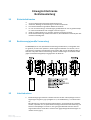 8
8
-
 9
9
-
 10
10
-
 11
11
-
 12
12
-
 13
13
-
 14
14
-
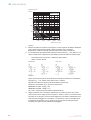 15
15
-
 16
16
-
 17
17
-
 18
18
-
 19
19
-
 20
20
-
 21
21
-
 22
22
-
 23
23
-
 24
24
-
 25
25
-
 26
26
-
 27
27
-
 28
28
-
 29
29
-
 30
30
-
 31
31
-
 32
32
-
 33
33
-
 34
34
-
 35
35
-
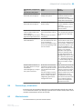 36
36
-
 37
37
-
 38
38
-
 39
39
-
 40
40
-
 41
41
-
 42
42
-
 43
43
-
 44
44
-
 45
45
-
 46
46
-
 47
47
-
 48
48
-
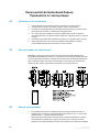 49
49
-
 50
50
-
 51
51
-
 52
52
-
 53
53
-
 54
54
-
 55
55


SICK WSE9-3N Instrucciones de operación
- Tipo
- Instrucciones de operación
- Este manual también es adecuado para
en otros idiomas
- français: SICK WSE9-3N Mode d'emploi
- italiano: SICK WSE9-3N Istruzioni per l'uso
- English: SICK WSE9-3N Operating instructions
- português: SICK WSE9-3N Instruções de operação
- 日本語: SICK WSE9-3N 取扱説明書
Artículos relacionados
-
SICK MultiPulse - WTB4-3P2100S13 Instrucciones de operación
-
-
-
-
-
-
SICK WS/WE18-3 Instrucciones de operación
-
-
-