SMA Sunny Boy 1100E Quick Installation Manual
- Tipo
- Quick Installation Manual

Sunny Boy 1100E
String-Wechselrichter / String Inverter
Onduleur String / Ondulador de Secencias
Kurzinstallationsanleitung
Quick Installation Guide
Instructions d’Installation Brèves
Instrucciones de Instalación Cortas


Die folgende Installations-
anleitung soll als Hilfe für die
Inbetriebnahme des Sunny
Boy 1100E dienen. Sie er-
setzt nicht das Handbuch des
Sunny Boy 1100E. Eine voll-
ständige Beschreibung aller
Funktionen des Sunny Boy
1100E ist in der Technischen
Beschreibung verfügbar.
Dort finden Sie außerdem
Informationen über die
Kommunikationsmöglichkei-
ten des Sunny Boy 1100E so-
wie alle einstellbaren
Parameter.
Bitte zuerst lesen:
Sunny Boy 1100E
Kurzinstallationsanleitung
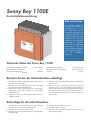
Technische Daten des Sunny Boy 1100E
Betrieb
Operation
Erdschluss
Earth Fault
Störung
Failure
Photovoltaik-Stringwechselrichter
Photovoltaic string
inverter
SWR 1100E
Eingangsspannungsbereich U
PV
: 139 V bis 400 V
Max. Eingangsstrom I
PVmax
: 10 A
Ausgangsnennleistung P
ACNenn
: 1000 W
Arbeitsbereich AC U
AC
: 198 V bis 251 V
Arbeitsbereich, Frequenz f
AC
: 49,8 bis 50,2 Hz
Gewicht: ca. 21 kg
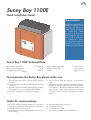
Beachten Sie bei der Inbetriebnahme unbedingt:
1. Die Inbetriebnahme des Sunny Boy darf nur durch qua-
lifiziertes Personal erfolgen.
2. Beachten Sie beim elektrischen Anschluss unbedingt
die unten angegebene Reihenfolge!
3. Überprüfen Sie die Leerlaufspannung der PV-Strings,
Spannungen über 400 V können zu irreparablen
Schäden führen!
4. Stellen Sie sicher, dass der Sunny Boy keine Transport-
schäden aufweist.
5. Öffnen Sie den Sunny Boy nicht, wenn er am Netz an-
geschlossen ist.
6. Trennen Sie den Sunny Boy niemals von der PV-
Spannung, bevor die AC-Spannung freigeschaltet ist
(Sicherung in der AC-Hausverteilung AUS). Das Ziehen
der Multi-Contact-Steckverbinder unter Last führt zu ei-
nem Lichtbogen im Stecker. Der Stecker muss dann er-
setzt werden.
Reihenfolge für die Inbetriebnahme:
1. Freischaltung des AC-Stromkreises für den Sunny Boy
(Sicherung in der AC-Hausverteilung AUS)
2. Montage des Sunny Boy (siehe Seite 2)
3. Überprüfung der PV-Leerlaufspannung und Anschluss
der PV-Strings
4. Montage des AC-Steckers (Seite 3)
5. Anschluss des AC-Steckers
6. Anschluss der AC-Spannung (Sicherung in der AC-
Hausverteilung EIN)

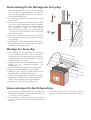
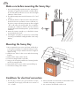
1. Der Montageuntergrund muss fest sein. Die Montage
des Sunny Boy auf Gipskartonplatten o. ä. kann auf
Grund der geringfügigen Vibrationen des Geräts zu
Geräuschentwicklung führen.
2. Die Umgebungstemperatur muss zwischen -25 °C und
+60 °C liegen.
3. Über dem Sunny Boy müssen mindestens 20 cm Platz
sein, um eine ausreichende Wärmeabfuhr zu gewähr-
leisten. Vermeiden Sie direkte Sonneneinstrahlung, hö-
here Temperaturen führen zu einer höheren
Verlustleistung. Bei Montage in einem Schaltschrank
o. ä. müssen Sie durch Ventilatoren für ausreichende
Wärmeabfuhr sorgen.
4. Montieren Sie den Sunny Boy senkrecht oder nach hin-
ten geneigt. Montieren Sie den Sunny Boy niemals nach
vorne geneigt!
5. Die Montage des Sunny Boy in Augenhöhe ist nicht un-
bedingt erforderlich, sie erleichtert aber das Ablesen
der LEDs oder des Sunny Display.
Voraussetzung für die Montage des Sunny Boy
Montage des Sunny Boy
Voraussetzungen für den Netzanschluss
°C
2
3
4
5
1
1. Der AC-Stecker zum Netzanschluss des Sunny Boy kann
handelsübliche Netzkabel mit Leitungsquerschnitten von
1,5 mm
2
bis 2,5 mm
2
aufnehmen.
2. Der Stromkreis, an dem der Sunny Boy angeschlossen
wird, muss mit einem 16-A-Sicherungsautomaten abgesi-
chert sein.
3. In dem Stromkreis zwischen der Sicherung und dem
Sunny Boy sind keine weiteren Verbraucher zulässig.
1. Wir empfehlen für die Befestigung des Sunny Boy
6 mm Sechskant-Schrauben sowie 8 mm Dübel.
Verwenden Sie bei der Außenmontage Schrauben aus
Edelstahl. Denken Sie bei der Montage des Sunny Boy
an das Gewicht von ca. 21 kg.
2. Markieren Sie mit Hilfe der Wandhalterung die zwei
Punkte für die Befestigungsschrauben der
Wandhalterung.
3. Bohren Sie die Löcher und führen Sie die Dübel ein.
4. Befestigen Sie die Wandhalterung an der Wand.
5. Hängen Sie den Sunny Boy mit den beiden oberen
Montagelaschen in die Wandhalterung ein.
6. Führen Sie die mitgelieferte Schraube in die untere
Haltelasche ein. Ziehen Sie diese Schraube fest und si-
chern Sie den Sunny Boy somit gegen Ausheben.
7. Überprüfen Sie den Sunny Boy auf festen Sitz.

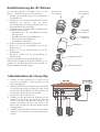
Je nach Querschnitt des AC-Kabels müssen Sie die
PG13,5- oder die PG16-Verschraubung benutzen.
1. Drücken Sie den Dichtungsring in den Klemmkorb
(nur bei PG13,5).
2. Schieben Sie nun zuerst die Druckschraube mit dem
Klemmkorb für PG13,5- oder die PG16-
Verschraubung über die Leitung. Danach schieben sie
die Gewindehülse über die Leitung.
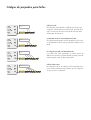
3. Schließen Sie nun die einzelnen Adern der Reihe nach
an den Buchseneinsatz an.
- Schutzleiter PE in die Schraubklemme mit dem
Erdungszeichen
- Neutralleiter N auf die Schraubklemme1
- Phase L auf die Schraubklemme 2
- Schraubklemme 3 bleibt frei
4. Prüfen Sie die Anschlussadern auf festen Sitz.
5. Drehen Sie nun die Gewindehülse fest auf den
Buchseneinsatz.
6. Drehen Sie nun die Druckschraube fest auf die
Gewindehülse.
7. Bei PG16: Drehen Sie die Verschraubung zur
Abdichtung fest.
Die AC-Kupplungsdose ist nun fertig konfektioniert.
Sollten Sie den Sunny Boy nicht gleich anschließen, so ver-
schließen Sie den Buchseneinsatz mit der ebenfalls im
Beipack enthaltenen Verschlusskappe.
1. Schalten Sie den Stromkreis ab, an dem Sie den
Sunny Boy anschließen wollen (Sicherung in der
Hausverteilung AUS).
2. Überprüfen Sie die PV-Leerlaufspannung und schließen
Sie die PV-Strings an den Sunny Boy an, indem Sie die
Multi-Contact-Steckverbinder auf die Anschlüsse auf
der Unterseite des Sunny Boy fest aufstecken.
3. Montieren Sie den AC-Stecker (s.o.).
4. Schließen Sie den AC-Stecker an die Buchse auf der
Unterseite des Sunny Boy an. Stecken Sie dazu den
Stecker vorsichtig in die Öffnung, drehen Sie den
Stecker unter leichtem Druck, bis der Stecker in die
Buchse sinkt. Schrauben Sie dann den Stecker mit dem
Gewindering fest.
5. Schließen Sie den Stromkreis mit der AC-Spannung an,
indem Sie die Sicherung in der Hausverteilung ein-
schalten.
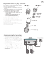
Konfektionierung des AC-Steckers
Inbetriebnahme des Sunny Boy
Buchseneinsatz
Gewindehülse
Dichtungsring
für PG13,5
Klemmkorb
Version PG13,5
Druckschraube
Version PG16
Druckschraube
Version PG13,5
Gewindering

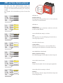
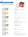
Die LEDs auf dem Gehäusedeckel zeigen den
Betriebszustand des Sunny Boy an. Einzelheiten entnehmen
Sie bitte der Technischen Beschreibung des Sunny Boy
1100E.
Im Folgenden die Zeichenerklärung für den Zustand der
LEDs:
LEDs auf dem Gehäusedeckel
Grüne LED blinkt im Sekundentakt
Warten, Netzüberwachung:
Die Startbedingungen für den Betrieb werden überprüft.
Grüne LED leuchtet konstant
Betrieb:
Einspeisebetrieb, MPP- oder Konstantspannungsbetrieb.
Rote LED leuchtet konstant
Isolationsfehler:
Erdschluss des PV-Generators oder Ausfall des Über-
spannungsschutzes (thermisch überwachte Varistoren).
Grüne LED erlischt ein Mal pro Sekunde
Derating:
Der Sunny Boy reduziert aufgrund überhöhter Temperatur
die Ausgangsleistung
.
LED aus
LED aus
LED aus
Alle LEDs aus
Nachtabschaltung:
Die Eingangsspannung ist kleiner als ca. 70 V und reicht
nicht für den normalen Betrieb.
Alle LEDs an
Initialisierung:
Eingangsspannung ist vorhanden, reicht aber noch nicht
für den normalen Betrieb.
Grüne LED blinkt drei Mal pro Sekunde
Stop:
Der Sunny Boy ist in einem Übergangs-Zustand oder ist
manuell gestoppt worden.
LED anLED an
LED an
LED an
1s
1s
1s
LED aus
LED aus
LED an
nicht relevant
nicht relevant
1s1s 1s
LED aus
LED aus
LED aus
LED an
nicht relevant
nicht relevant
LED aus
nicht relevant
nicht relevant
1s 1s 1s

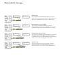
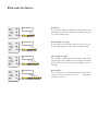
Blink-Codes für Störungen
Netzstörung:
Der Sunny Boy zeigt eine Netzstörung an, wenn die
Netzfrequenz, die Netzspannung oder die Netzfrequenz-
Änderung außerhalb der tolerierbaren Werte liegt.
Netzimpedanz ist zu hoch (ENS):
Der Sunny Boy zeigt diese Meldung, wenn die
Netzimpedanzwerte der ENS außerhalb des tolerierba-
ren Bereichs liegen oder ein Impedanzsprung vorliegt.
Eingangsspannung ist zu hoch:
Der Sunny Boy 1100E zeigt diese Meldung, wenn die PV-
Eingangsspannung über 400 V liegt. Der Sunny Boy
muss dann sofort von der PV-Eingangsspannung getrennt
werden, um eine Beschädigung zu vermeiden!
Gerätestörung:
Der Sunny Boy hat eine Störung, die den normalen
Betrieb verhindert. Eine Elektrofachkraft muss das
Gerät überprüfen, wenn diese Störung gehäuft auftritt.
Die gelbe LED leuchtet 3
Mal kurz hintereinander
5s
3s 1s
LED an
LED aus
1s 1s
Die Meldung wird 3 Mal
wiederholt und beginnt
dann von vorn.
Die Meldung wird 3 Mal
wiederholt und beginnt
dann von vorn.
5s
3s 1s
LED an
LED aus
Die gelbe LED leuchtet 2
Mal kurz hintereinander
Die gelbe LED leuchtet 4
Mal kurz hintereinander
5s
3s 1s
LED an
LED aus
1s 1s 1s
Die Meldung wird 3 Mal
wiederholt und beginnt
dann von vorn.
Die gelbe LED leuchtet 5
Mal kurz hintereinander
5s
3s 1s
LED an
LED aus
1s 1s 1s 1s
Die Meldung wird 3 Mal
wiederholt und beginnt
dann von vorn.


GB
The following instructions for
installation will help you to
commission the Sunny Boy
1100E. They do not replace
the Sunny Boy 1100E
Manual. You will find a com-
plete description of all func-
tions as well as information
on communication equip-
ment and all definable pa-
rameters in the Sunny Boy
1100E Technical Description.
Please read first
Sunny Boy 1100E
Quick Installation Guide
Sunny Boy 1100E Technical Data
Betrieb
Operation
Erdschluss
Earth Fault
Störung
Failure
Photovoltaik-Stringwechselrichter
Photovoltaic
s
tring
i
nverter
SW
R 1100E
Input voltage range V
PV
: 139 V - 400 V
Max. input current I
PVmax
: 10 A
Nominal output power P
ACnom
: 1000 W
Output voltage range V
AC
: 198 V - 251 V
Frequency range f
AC
: 49.8 - 50.2 Hz
Weight: approx. 21 kg
To commission the Sunny Boy please make sure:
1. The Sunny Boy may only be commissioned by qualified
personnel.
2. Follow the order below when establishing the electrical
connection!
3. Check the open circuit voltage of the PV strings. Voltages
above 400 V can cause non-repairable damage!
4. Check the Sunny Boy for any transport damage.
5. Do not open the Sunny Boy when it is connected to the
grid.
6. Never disconnect the Sunny Boy from the PV voltage be-
fore the AC voltage has been disconnected (remove the
fuse in the house distribution). Pulling the Multi-Contact
plug connectors while under load results in an electric
arc in the connector which consequently has to be re-
placed.
Order for commissioning:
1. Disconnect the AC circuit the Sunny Boy is connected to
(open the circuit breaker in the AC house distribution).
2. Install the Sunny Boy (see page 2).
3. Check the PV open circuit voltage and the connection of
the PV strings.
4. Assemble the AC plug (see page 3).
5. Connect the AC plug.
6. Connect the AC voltage
(close the house distribution circuit breaker).

GB
1. The mounting background must be firm. Mounting the
Sunny Boy on gypsum plaster board or similar materi-
al can result in the production of noise due to the slight
vibrations of the inverter.
2. The ambient temperature must be between -25 °C and
+60 °C.
3. A minimum distance of 20 cm must be clear above the
inverter for free air circulation to ensure sufficient coo-
ling. Do not expose the string inverter to direct sunlight
- this could reduce the energy yield. If you install the
Sunny Boy in a cabinet or closet etc., the air circulation
must be sufficient for heat dissipation - provide external
ventilation.
4. Mount the inverter straight up or tilted back. Never
mount it tilted to the front!
5. Mounting the Sunny Boy on eye level is not absolutely
necessary, but facilitates reading the LEDs or the Sunny
Display.
Make sure before mounting the Sunny Boy:
Mounting the Sunny Boy
Conditions for electrical connection
°C
2
3
4
5
1
1. The AC plug connector for grid connection accepts
commercial power supply cords with cross-sections of
1.5 - 2.5 mm².
2. We recommend a 16 A automatic circuit breaker for the
circuit the Sunny Boy is connected to.
3. No consumers are allowed on this circuit.
1. We recommend 6 mm screws and 8 mm wall anchors
to mount the Sunny Boy. For outside mounting use stain-
less steel screws. Keep in mind the inverter's weight of
approx. 21 kg.
2. Mark the two holes for the screws with the mounting
bracket.
3. Drill the holes and put in the dowels.
4. Fix the mounting bracket on the wall.
5. Hang up the Sunny Boy with the two fastening latches
into the mounting bracket.
6. Fasten the bottom screw in order to prevent lifting up.
7. Check the mounting of the inverter.

GB
Choose the PG13.5 or PG16 fastening clamp depending
on the cross-section of the AC cable.
1. Push the rubber ring into the fastening case (only for
PG13.5).
2. Put the cable through the PG 13.5 or 16 cable seal with
the fastening case and through the socket tube.
3. Connect the wires of the AC cable as follows:
- Protective Earth (PE) to the terminal with the
"ground" symbol
- Neutral wire to the terminal marked with "1"
- Phase L to the terminal marked with "2"
- The terminal marked with "3" is not used.
4. Make sure that all wires are firmly connected.
5. Push the socket tube firmly onto the socket.
6. Screw the cable seal firmly onto the socket tube.
7. For cables that require the PG16 gland: Tighten the bolt
of the PG16 gland.
The AC connector socket is now ready to use.
Seal the AC connector socket in case you do not insert it in-
to the Sunny Boy immediately.
1. Disconnect the circuit where to connect the Sunny Boy
(open the circuit breaker of the supply lead).
2. Check the open circuit voltage of the PV strings and
connect them to the Sunny Boy by firmly plugging the
Multi-Contact connectors onto the openings at the bott-
tom of the Sunny Boy.
3. Assemble the AC plug connector.
4. Connect the AC plug to the socket on the bottom of the
Sunny Boy. Carefully insert the plug into the opening,
turn the plug with light pressure until it sinks into the so-
cket. Tighten the plug by the bolt of the gland.
5. Connect the AC voltage by closing the circuit breaker of
the supply lead.
Preparation of the AC plug connector
Commissioning the Sunny Boy

GB
The LEDs on the lid display the operating state the Sunny
Boy is in. For details please refer to the Sunny Boy 1100E
Technical Description. Description of the symbols used in the
following section:
LEDs on the front panel
Green LED flashes three times per second
Stop:
The Sunny Boy is changing its operating condition or is in
a manually initiated condition.
Green LED flashes once per second
Waiting, checking grid:
Starting conditions are being checked.
Green LED flashes constantly
Operation:
Feeding grid, MPP or constant voltage mode.
Red LED flashes constantly
Isolation failure:
Earth fault of the PV-panels or failure of surge voltage pro-
tection (thermally monitored varistors).
Green LED is off once a second
Derating:
The Sunny Boy has detected an internal overtemperature
due to temporary overload and is derating the output po-
wer in order to avoid internal damage.
All LEDs off
Standby (night):
The input voltage is below 70 V and not yet sufficient for
normal operation.
LED off
LED off
LED off
LED onLED
LED on
LED on
All LEDs on
Initialization:
The input voltage is not yet sufficient for normal opera-
tion.
1s
1s
1s
LED off
LED off
LED on
not relevant
not relevant
1s1s 1s
LED off
LED off
LED aus
not relevant
not relevant
LED on
LED aus
not relevant
not relevant
1s 1s 1s

Blink codes for failures
Grid failure:
The Sunny Boy displays a grid failure if the grid frequency,
grid voltage or the rate of change of the grid frequency are
out of the tolerable range.
The yellow LED flashes 3
times.
5s
3s 1s
LED on
LED off
1s 1s
Input voltage too high:
The Sunny Boy 1100E displays this blinking code if the PV
input voltage is above 400 V. Disconnect the grid and then
the PV-panels from the Sunny Boy immediately to prevent
damage!
The yellow LED flashes 4
times.
5s
3s 1s
LED on
LED off
1s 1s 1s
The yellow LED flashes 5
times.
5s
3s 1s
LED on
LED off
1s 1s 1s 1s
5s
3s 1s
LED on
LED off
The yellow LED flashes
twice.
1s
Grid impedance too high:
The Sunny Boy has detected a failure based on non-per-
missible grid impedance values measured by the MSD.
Device failure:
The Sunny Boy is in a condition that makes it impossible to
return to normal operation. It has to be checked by a
qualified technician.


F
Les instructions d'installation
suivantes devraient aider le
lecteur à mettre en service le
Sunny Boy 1100E. Elles ne
remplacent pas le manuel du
Sunny Boy 1100E. Une des-
cription complète de tous les
fonctions du Sunny Boy
1100E est inclue dans la
Description Technique (du
Sunny Boy 1100E). Vous y
trouverez également des in-
formations sur les possibilités
de communication du Sunny
Boy 1100E ainsi que tous les
paramètres ajustables.
Lire d'abord s.v.p. :
Sunny Boy 1100E
Instructions d'installation brèves
Données techniques du Sunny Boy 1100E
Betrieb
Operation
Erdschluss
Earth Fault
Störung
Failure
Photovoltaik-Stringwechselrichter
Photovoltaic string
i
nverter
SWR 1100E
Plage de tension d'entrée, U
PV
: 139 V à 400 V
Courant d'entrée max., I
PVmax
: 10 A
Puissance nominale de sortie P
CAnom
: 1000 W
Portée CA, U
CA
: 198 V à 251 V
Portée fréquence f
CA
: 49,8 à 50,2 Hz
Poids : env. 21 kg
Attention lors de la mise en service
1. Le Sunny Boy ne doit être mis en service que par du per-
sonnel qualifié.
2. Lors de la connexion électrique suivre l'ordre ci-dess-
sous!
3. Examiner la tension à vide des lignes de modules PV
("strings"). Les tensions au delà de 400 V peuvent ré-
sulter en dommages irréparables !
4. Assurer que le Sunny Boy ne montre pas de dommages
de transport.
5. Ne pas ouvrir le Sunny Boy quand il est branché sur le
réseau.
6. Ne jamais déconnecter le Sunny Boy de la tension PV
avant que la tension CA ne soit déconnectée (coupe-cir-
cuit dans la distribution de maison interrompu). Si on ti-
re les connecteurs Multi-Contact pendant qu'ils sont
chargés il en résulte un arc électrique dans le connec-
teur qui alors doit être remplacé.
Ordre de la mise en service
1. Déconnexion du circuit CA pour le Sunny Boy (coupe-
circuit dans la distribution de maison interrompu).
2. Montage du Sunny Boy (voir page 2).
3. Contrôle de la tension PV à vide et connexion des
strings PV.
4. Montage de la fiche CA (page 3).
5. Connexion de la fiche CA
6. Connexion de la tension CA
(coupe-circuit dans la distribution de maison fermé)

F
1. La surface de montage doit être firme. Le montage du
Sunny Boy sur des plateaux de carton en plâtre ou des
matériaux similaires peut résulter en la production de
bruit à cause de vibrations minimes de l'appareil.
2. La température ambiante doit être entre -25 °C et
+60 °C.
3. Au-dessus du Sunny Boy il doit y avoir au minimum un
espace de 20 cm pour garantir une évacuation de cha-
leur suffisante. Eviter une radiation solaire directe. Les
températures assez hautes résultent en une dissipation
plus élevée. Si vous montez le Sunny Boy en une ar-
moire de commande p. ex. assurer une évacuation de
chaleur suffisante par des ventilateurs.
4. Monter le Sunny Boy à plomb ou incliné en arrière. Ne
jamais monter le Sunny Boy incliné à l'avant !
5. Le montage du Sunny Boy à la hauteur des yeux n'est
pas absolument nécessaire, mais simplifie lire les DELs
ou le Sunny Display.
Conditions préalables pour le montage du Sunny Boy
Montage du Sunny Boy
Conditions préalables pour la connexion au réseau
°C
2
3
4
5
1
1. La fiche CA pour connexion du Sunny Boy au réseau
peut recevoir câbles d'alimentation usuels avec coupes
transversales de 1,5 mm² à 2,5 mm².
2. Le circuit où le Sunny Boy est connecté doit avoir un
interrupteur automatique de 16 A.
3. Dans le circuit entre le fusible et le Sunny Boy d'autres
consommateurs ne sont pas admissibles.
1. Nous recommandons fixer le Sunny Boy avec des vis à
tête hexagonale de 6 mm et des chevilles de 8 mm.
Utiliser des vis d'acier spécial lors d'un montage en de-
hors. Lors du montage tenir compte du poids du Sunny
Boy d'environ 21 kg.
2. Marquer les trois points pour les vis de fixation du Sunny
Boy à l'aide du gabarit de perçage.
3. Perçer les trous et introduiser les chevilles.
4. Visser deux vis jusqu'à ce qu'il reste environ 4 mm qui
sortent des deux trous supérieurs.
5. Accrocher le Sunny Boy dans ces deux vis avec les deux
pattes de montage supérieures.
6. Introduire une vis dans la patte basse. Visser cette vis de
sorte que personne ne peut lever et laisser tomber le
Sunny Boy par inadvertance.
7. Contrôler l'installation ferme du Sunny Boy.

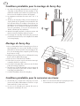
F
Selon la coupe transversale du câble CA utiliser le raccord
PG 13,5 ou PG 16.
1. Pousser l'anneau obturateur dans le pannier serre (avec
PG 13,5 seulement).
2. Pousser d'abord le raccord PG16 ou PG 13,5 (ce der-
nier avec le pannier serre) sur le câble. Ensuite pousser
la bouille de filet sur le câble.
3. Connecter les différents fils à l'insert boîte l'un après
l'autre.
- Fil protecteur de masse dans serre-fils avec le signe
terre
- Fil neutre dans serre-fils 1
- Phase dans serre-fils 2
- Serre-fils 3 reste vacant
4. Contrôler si les fils sont solidement connectés.
5. Tourner la bouille de filet fermement sur l'insert boîte.
6. Tourner le raccord fermement sur la bouille de filet.
7. En cas de PG16: Fixer le filet de l'obturation.
La fiche CA est maintenant préparée.
Si vous ne connectez pas le Sunny Boy directement, fermer
l'insert boîte avec le chapeau d'obturation inclut dans la liv-
raison du Sunny Boy.
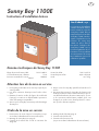
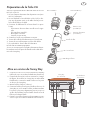
1. Couper le circuit où vous voulez connecter le Sunny Boy
(enlever le coupe-circuit dans la distribution de maison).
2. Contrôler la tension PV à vide et connecter les "strings"
PV (lignes de modules) au Sunny Boy en embrochant
fermement les connecteurs Multi-Contact sur les prises
au dessous du Sunny Boy.
3. Monter la fiche CA (voir ci-dessus).
4. Connecter la fiche CA à la prise femelle au dessous du
Sunny Boy. A ce fin mettre la fiche prudemment dans
l'ouverture y la tourner légèrement pressée jusqu'à ce
qu'elle descend dans la prise femelle. Ensuite visser la
fiche avec la bague filetée.
5. Fermer le circuit avec la tension CA en mettant sous ten-
sion le coupe-circuit dans la distribution de la maison.
Préparation de la fiche CA
Mise en service du Sunny Boy
Insert bo teT
Bouille de filet
Anneau obturateur
pour PG13,5
Pannier serre
pour PG13,5
Raccord PG16
Raccord PG13,5
Bague filetée
2
3
String 2 String 1
Sunny Boy
(vue d’en bas)
4
5
1
CA distribution
de la maison

F
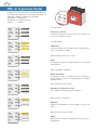
Les DELs sur le couvercle de la boîte montrent l'état de fonc-
tion-nement du Sunny Boy. Lire la Description Technique du
Sunny Boy 1100E pour obtenir plus de détails.
“Operation” = “Opération”,
“Earth Fault” = “Contact à la terre”,
“Failure” = “Défaut”.
DELs sur le panneau frontal
DEL vert brille trois fois par seconde
Arrêt:
Le Sunny Boy est dans un état de transition ou a été arrêté
manuellement.
DEL vert brille fois par seconde
Attendant, surveillance du réseau:
Les conditions de démarrage sont examinées.
DEL vert brille constamment
Opération:
Opération d'alimentation en mode MPP ou tension con-
stante.
DEL rouge brille constamment
Défaut d'isolement:
Le générateur solaire a du contact à la terre ou bien la pro-
tection contre les surtensions a failli (varistances surveillées
thermiquement).
DEL vert expire fois par seconde
Défaut:
Défaut interne ou externe, identification exacte selon le co-
de clignotant.
Tous DEL éteinte
Déconnexion à la nuit:
La tension d'entrée est moins de 70 V et ne suffit pas en-
core pour l'opération normal.
Tous DEL allumée
Initialisation:
La tension d'entrée est disponible, mais ne suffit pas enco-
re pour l'opération normale.
DEL éteinte
DEL éteinte
DEL éteinte
DEL allumée
DEL allumée
DEL allumée
1s
1s
1s
DEL éteinte
DEL éteinte
DEL allumée
L'état insignifiant
L'état insignifiant
1s1s 1s
DEL éteinte
DEL éteinte
LED aus
L'état insignifiant
L'état insignifiant
DEL allumée
LED aus
L'état insignifiant
L'état insignifiant
1s 1s 1s

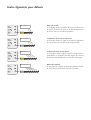
Défaut de réseau:
Le Sunny Boy montre un défaut de réseau si la fréquence
du réseau, la tension du réseau ou le change de fréquence
du réseau sont hors des valeurs tolérables.
Le DEL jaune brille 2
fois.
5s
3s 1s
DEL allumée
DEL éteinte
1s
Codes clignotants pour défauts
L'impédance du réseau est trop haute:
Le Sunny Boy montre ce signal si les valeurs d'impédance
du réseau mesurées sont hors de la plage tolérable.
Le DEL jaune brille 3
fois.
5s
3s 1s
DEL allumée
DEL éteinte
1s 1s
La tension d'entrée est trop haute:
Le Sunny Boy montre ce signal si la tension d'entrée PV sur-
monte 400 V. Le Sunny Boy doit être séparé de la tension
d'entrée PV immédiatement pour éviter des dommages!
Le DEL jaune brille 4
fois.
5s
3s 1s
DEL allumée
DEL éteinte
1s 1s 1s
Le DEL jaune brille 5
fois.
5s
3s 1s
DEL allumée
DEL éteinte
1s 1s 1s 1s
Défaut de l'appareil:
Le Sunny Boy a un défaut qui dérange l'opération norma-
le. Un technicien qualifié doit examiner l'onduleur.


E
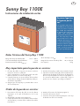
Las siguientes instrucciones
de instalación le sirven para
poner en servicio el Sunny
Boy 1100E. No reemplazan
el manual del Sunny Boy
1100E. Una descripción
completa de todas las funcio-
nes del Sunny Boy 1100E
está incluida en la corres-
pondiente Descripción Téc-
nica. Encontrará también in-
formación sobre las posibili-
dades de comunicación del
equipo, y todos los paráme-
tros que es posible ajustar.
En primer lugar leer
lo siguiente por fa-
vor:
Sunny Boy 1100E
Instrucciones de instalación cortas
Datos Técnicos del Sunny Boy 1100E
Betrieb
Operation
Erdschluss
Earth Fault
Störung
Failure
Photovoltaik-Stringwechselrichter
Photovoltaic string
i
nverter
SWR 1100E
Rango del voltaje de entrada U
PV
: 139 V - 400 V
Corriente máxima de entrada I
PVmax
: 10 A
Potencia nominal de salida P
CAnom
: 1000 W
Área de trabajo CA U
CA
: 198 V - 251 V
Rango de frecuencias de trabajo f
CA
: 49,8 - 50,2 Hz
Peso (aprox.): 21 kg
Muy importante para la puesta en servicio:
1. El Sunny Boy debe ser puesto en servicio exclusiva-
mente por un técnico cualificado.
2. Seguir estrictamente el orden mencionado más ade-
lante a la hora de conectar el Sunny Boy!
3. Controlar la tensión en circuito abierto de la instalaci-
ón fotovoltaica. Voltajes de más de 400 V pueden pro-
ducir daños irreparables.
4. Asegurar que el Sunny Boy no presenta daños causa-
dos en el transporte.
5. No abrir el Sunny Boy cuando está conectado a la red.
6. Jamás desconectar el Sunny Boy de la instalación foto-
voltaica antes de aislarlo de la tensión de alterna (fusi-
ble en la caja de distribución de la casa apagado). Si
los conectores Multi-Contact se abren bajo carga se
produce un arco eléctrico que obliga a sustituirlos.
Orden de la puesta en servicio:
1. Desconexión del Sunny Boy del circuito de alterna
(interruptor en la caja de distribución de la casa
abierto)
2. Montaje del Sunny Boy (véase página 2)
3. Control de la tensión en circuito abierto de la instalaci-
ón fotovoltaica y conexión de las cadenas de módulos
fotovoltaicos
4. Montaje del conector de CA (véase página 3)
5. Conexión del conector de CA
6. Conexión de la tensión alterna (interruptor en la caja
de distribución de la casa cerrado)

E
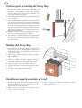
1. El fondo del montaje debe ser firme. El montaje del
Sunny Boy sobre paneles de cartón yeso o similares
puede resultar en la producción de ruido debido a las
vibraciones mínimas del aparato.
2. La temperatura ambiental tiene que estar situada entre
-25 °C y +60 °C.
3. Tiene que dejarse libre una distancia mínima de 20 cm
por encima del inversor para asegurar una disipación
de calor suficiente. No exponer el inversor a la luz di-
recta del sol. Temperaturas más altas podrían reducir la
eficiencia. Si monta el Sunny Boy en un armario de dis-
tribución, asegurar que existe una eliminación de calor
por ventilación suficiente.
4. Montar el inversor vertical o inclinado hacia atrás.
Nunca se montará inclinado hacia delante!
5. La instalación a una altura nivelada no es imprescindi-
ble, pero hace posible leer fácilmente los diodos LED o
el Sunny Display.
Criterios para el montaje del Sunny Boy
Montaje del Sunny Boy
Condiciones para la conexión a la red
°C
2
3
4
5
1
1. El enchufe CA para conexión del Sunny Boy a la red es
apto para cables de red de uso comercial con sección
transversal de 1,5 mm² a 2,5 mm².
2. Debe conectarse un automático de 16 A al circuito al
cual se conecta el Sunny Boy.
3. En el circuito entre el fusible y el Sunny Boy no se per-
miten consumidores.
1. Recomendamos tornillos de cabeza hexagonal de
6 mm y tacos de 8 mm. Para montajes a la intemperie,
utilizar tornillos de acero inoxidable. Considerar un pe-
so de aprox. 21 kg.
2. Marcar los tres agujeros para los tornillos con la plan-
tilla de taladrado.
3. Taladrar los agujeros e introducir los tacos.
4. Colocar los tornillos de ambos agujeros superiores
y atornillarlos hasta que sobresalgan aprox. 4 mm.
5. Colgar el inversor de los dos tornillos superiores.
6. Fijar el tornillo inferior con el fin de impedir el levanta-
miento.
7. Comprobar el montaje firme del inversor.

E
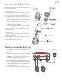
Según la sección transversal del cable CA utilizar la junta
de rosca PG 13,5 o PG 16.
1. Apretar el anillo de junta en la cesta de borne (sólo en
caso de PG 13,5).
2. Primeramente meter la junta de rosca PG 13,5 con la
cesta de borne o la junta de rosca PG 16 sobre el ca-
ble. Luego meter el casquillo roscado sobre el cable.
3. Conectar por orden los hilos a través de los orificios a
los terminales correspondientes:
- Conductor de protección PE en el terminal de rosca
con el símbolo de puesta a tierra
- Conductor neutro N en el terminal de rosca 1
- Fase L en el terminal de rosca 2
- Terminal de rosca 3 queda libre
4. Controlar que los hilos quedan conectados fuerte-
mente.
5. Destorcer el casquillo roscado fuertemente sobre el in-
serto de enchufe.
6. Destorcer la junta de rosca fuertemente sobre el cas-
quillo roscado.
7. Con PG 16: Apretar la junta de rosca fuertemente pa-
ra impermeabilización.
Ahora el enchufe de CA está preparado. Si no conecta el
Sunny Boy directamente cerrar el orificio de enchufe con el
capuchón también incluido en el envío.
1. Desconectar el circuito al que quiere conectar el Sunny
Boy (fusible en la caja de distribución de la casa apa-
gado).
2. Comprobar el voltaje en vacío del sistema fotovoltaico
y conectar los módulos PV al Sunny Boy enchufando
fuertemente los conectores Multi-Contact sobre las to-
mas de la superficie inferior del Sunny Boy.
3. Montar el enchufe de CA (véase arriba).
4. Conectar el enchufe de CA al borne en la superficie in-
ferior del Sunny Boy. Meter el enchufe en el agujero con
cuidado, girar el enchufe con presión ligera hasta que
el enchufe descienda en el borne. Luego atornillar el en-
chufe con el anillo de rosca.
5. Conectar el circuito al voltaje CA encendiendo el fusi-
ble en la distribución de la casa.
Preparación del enchufe de CA
Puesta en servicio del Sunny Boy
2
3
String 2 String 1
Sunny Boy
(vista de abajo)
4
5
1
CA distribución
de la casa

E
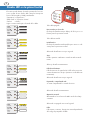
El usuario puede obtener el estado operativo de los inver-
sores a partir de tres diodos LED. Véase la Descripción
Técnica del Sunny Boy 1100E para detalles.
“Operation” = “Operación”;
“Earth Fault” = “Conexión a tierra”
“Failure” = “Fallo”
Signos convencionales para el estado de los LEDs:
Diodos LED en la placa frontal
Todos LED apagado
Desconexión por la noche:
El voltaje de entrada está por debajo de 70 V y no es su-
ficiente para la operación normal.
Todos LED encendido
Inicialización:
El voltaje de entrada está disponible pero aún no es sufi-
ciente para la operación normal.
LED verde destella tres veces por segundo
Stop:
Estado operativo cambiante o estado iniciado manual-
mente.
LED verde destella una vez por segundo
Esperando, comprobando red:
Se están comprobando los estados de inicio.
LED verde es apagado una vez al segundo
Fallo:
Fallo interno o externo, descripción exacta dependiendo
del código de parpadeo del LED.
LED verde destella constantemente
Operación normal:
Alimentando a la red en modo MPP o modo de voltaje
constante.
LED rojo destella constantemente
Fallo de aislamiento:
Fallo de tierra en los paneles PV o fallo en la protección
contra sobretensiones de pico (varistores controlados tér-
micamente).
LED apagado
LED apagado
LED apagado
LED encendidoLED
LED encendido
LED encendido
1s
1s
1s
LED apagado
LED apagado
LED encendido
Estado no definido
Estado no definido
1s1s 1s
LED apagado
LED apagado
LED aus
Estado no definido
LED encendido
Estado no definido
LED aus
Estado no definido
1s 1s 1s
Estado no definido

Códigos de parpadeo para fallos
Fallo de la red:
El Sunny Boy está indicando un fallo de la red que está
originado cuando la frecuencia de la red, el voltaje de la
red o la variación de la frecuencia de la red están fuera
del margen de tolerancia.
El voltaje de entrada está demasiado alto:
Los paneles PV están generando un voltaje mayor de
400 V. Desconectar los paneles PV del Sunny Boy inmedi-
atamente para evitar un daño irreparable!
La impedancia de la red está demasiado alta:
El Sunny Boy ha detectado un fallo basándose en los valo-
res de impedancia de la red no permisibles medidos por la
MSD.
Fallo del dispositivo:
El Sunny Boy está en un estado que hace imposible el re-
torno al funcionamiento normal y tiene que ser comproba-
do por un técnico cualificado.
El LED amarillo destella
3 veces.
5s
3s 1s
LED encendido
LED apagado
1s 1s
El LED amarillo destella
4 veces.
1s 1s 1s 1s
5s
3s
LED encendido
LED apagado
El LED amarillo destella
5 veces.
1s 1s 1s 1s 1s
5s
3s
LED encendido
LED apagado
1s
El LED amarillo destella
2 veces.
1s
5s
3s
LED encendido
LED apagado


SMA Regelsysteme GmbH
www.SMA.de
Hannoversche Str. 1-5
34266 Niestetal
Germany
Tel. +49 561 9522 -0
Fax +49 561 9522 -100
www. SMA.de
SB1100E-12:QX1504 - “TBK-SB11E”
Transcripción de documentos
Sunny Boy 1100E String-Wechselrichter / String Inverter Onduleur String / Ondulador de Secencias Kurzinstallationsanleitung Quick Installation Guide Instructions d’Installation Brèves Instrucciones de Instalación Cortas Sunny Boy 1100E Kurzinstallationsanleitung Bitte zuerst lesen: SWR 1100 Phot ov Phot oltaik-S ovol taic tringwec strin g invehselricht er rter E Die folgende Installationsanleitung soll als Hilfe für die Inbetriebnahme des Sunny Boy 1100E dienen. Sie ersetzt nicht das Handbuch des Sunny Boy 1100E. Eine vollständige Beschreibung aller Funktionen des Sunny Boy 1100E ist in der Technischen Beschreibung verfügbar. Dort finden Sie außerdem Informationen über die Kommunikationsmöglichkeiten des Sunny Boy 1100E sowie alle einstellbaren Parameter. Betri eb Ope ratio n Erds ch Earth luss Faul t Störun Failu g re Technische Daten des Sunny Boy 1100E Eingangsspannungsbereich UPV: Max. Eingangsstrom IPVmax: Ausgangsnennleistung PACNenn: 139 V bis 400 V 10 A 1000 W Arbeitsbereich AC UAC: 198 V bis 251 V Arbeitsbereich, Frequenz fAC: 49,8 bis 50,2 Hz Gewicht: ca. 21 kg Beachten Sie bei der Inbetriebnahme unbedingt: 1. Die Inbetriebnahme des Sunny Boy darf nur durch qualifiziertes Personal erfolgen. 2. Beachten Sie beim elektrischen Anschluss unbedingt die unten angegebene Reihenfolge! 3. Überprüfen Sie die Leerlaufspannung der PV-Strings, Spannungen über 400 V können zu irreparablen Schäden führen! 4. Stellen Sie sicher, dass der Sunny Boy keine Transportschäden aufweist. 5. Öffnen Sie den Sunny Boy nicht, wenn er am Netz angeschlossen ist. 6. Trennen Sie den Sunny Boy niemals von der PVSpannung, bevor die AC-Spannung freigeschaltet ist (Sicherung in der AC-Hausverteilung AUS). Das Ziehen der Multi-Contact-Steckverbinder unter Last führt zu einem Lichtbogen im Stecker. Der Stecker muss dann ersetzt werden. Reihenfolge für die Inbetriebnahme: 1. Freischaltung des AC-Stromkreises für den Sunny Boy (Sicherung in der AC-Hausverteilung AUS) 2. Montage des Sunny Boy (siehe Seite 2) 3. Überprüfung der PV-Leerlaufspannung und Anschluss der PV-Strings 4. Montage des AC-Steckers (Seite 3) 5. Anschluss des AC-Steckers 6. Anschluss der AC-Spannung (Sicherung in der ACHausverteilung EIN) Voraussetzung für die Montage des Sunny Boy 1. Der Montageuntergrund muss fest sein. Die Montage des Sunny Boy auf Gipskartonplatten o. ä. kann auf Grund der geringfügigen Vibrationen des Geräts zu Geräuschentwicklung führen. 2. Die Umgebungstemperatur muss zwischen -25 °C und +60 °C liegen. 3. Über dem Sunny Boy müssen mindestens 20 cm Platz sein, um eine ausreichende Wärmeabfuhr zu gewährleisten. Vermeiden Sie direkte Sonneneinstrahlung, höhere Temperaturen führen zu einer höheren Verlustleistung. Bei Montage in einem Schaltschrank o. ä. müssen Sie durch Ventilatoren für ausreichende Wärmeabfuhr sorgen. 4. Montieren Sie den Sunny Boy senkrecht oder nach hinten geneigt. Montieren Sie den Sunny Boy niemals nach vorne geneigt! 5. Die Montage des Sunny Boy in Augenhöhe ist nicht unbedingt erforderlich, sie erleichtert aber das Ablesen der LEDs oder des Sunny Display. 2 °C 3 4 1 5 Montage des Sunny Boy 1. Wir empfehlen für die Befestigung des Sunny Boy 6 mm Sechskant-Schrauben sowie 8 mm Dübel. Verwenden Sie bei der Außenmontage Schrauben aus Edelstahl. Denken Sie bei der Montage des Sunny Boy an das Gewicht von ca. 21 kg. 2. Markieren Sie mit Hilfe der Wandhalterung die zwei Punkte für die Befestigungsschrauben der Wandhalterung. 3. Bohren Sie die Löcher und führen Sie die Dübel ein. 4. Befestigen Sie die Wandhalterung an der Wand. 5. Hängen Sie den Sunny Boy mit den beiden oberen Montagelaschen in die Wandhalterung ein. 6. Führen Sie die mitgelieferte Schraube in die untere Haltelasche ein. Ziehen Sie diese Schraube fest und sichern Sie den Sunny Boy somit gegen Ausheben. 7. Überprüfen Sie den Sunny Boy auf festen Sitz. Voraussetzungen für den Netzanschluss 1. Der AC-Stecker zum Netzanschluss des Sunny Boy kann handelsübliche Netzkabel mit Leitungsquerschnitten von 1,5 mm2 bis 2,5 mm2 aufnehmen. 2. Der Stromkreis, an dem der Sunny Boy angeschlossen wird, muss mit einem 16-A-Sicherungsautomaten abgesichert sein. 3. In dem Stromkreis zwischen der Sicherung und dem Sunny Boy sind keine weiteren Verbraucher zulässig. Konfektionierung des AC-Steckers Je nach Querschnitt des AC-Kabels müssen Sie die PG13,5- oder die PG16-Verschraubung benutzen. 1. Drücken Sie den Dichtungsring in den Klemmkorb (nur bei PG13,5). 2. Schieben Sie nun zuerst die Druckschraube mit dem Klemmkorb für PG13,5- oder die PG16Verschraubung über die Leitung. Danach schieben sie die Gewindehülse über die Leitung. 3. Schließen Sie nun die einzelnen Adern der Reihe nach an den Buchseneinsatz an. - Schutzleiter PE in die Schraubklemme mit dem Erdungszeichen - Neutralleiter N auf die Schraubklemme1 - Phase L auf die Schraubklemme 2 - Schraubklemme 3 bleibt frei 4. Prüfen Sie die Anschlussadern auf festen Sitz. 5. Drehen Sie nun die Gewindehülse fest auf den Buchseneinsatz. 6. Drehen Sie nun die Druckschraube fest auf die Gewindehülse. 7. Bei PG16: Drehen Sie die Verschraubung zur Abdichtung fest. Die AC-Kupplungsdose ist nun fertig konfektioniert. Sollten Sie den Sunny Boy nicht gleich anschließen, so verschließen Sie den Buchseneinsatz mit der ebenfalls im Beipack enthaltenen Verschlusskappe. Inbetriebnahme des Sunny Boy 1. Schalten Sie den Stromkreis ab, an dem Sie den Sunny Boy anschließen wollen (Sicherung in der Hausverteilung AUS). 2. Überprüfen Sie die PV-Leerlaufspannung und schließen Sie die PV-Strings an den Sunny Boy an, indem Sie die Multi-Contact-Steckverbinder auf die Anschlüsse auf der Unterseite des Sunny Boy fest aufstecken. 3. Montieren Sie den AC-Stecker (s.o.). 4. Schließen Sie den AC-Stecker an die Buchse auf der Unterseite des Sunny Boy an. Stecken Sie dazu den Stecker vorsichtig in die Öffnung, drehen Sie den Stecker unter leichtem Druck, bis der Stecker in die Buchse sinkt. Schrauben Sie dann den Stecker mit dem Gewindering fest. 5. Schließen Sie den Stromkreis mit der AC-Spannung an, indem Sie die Sicherung in der Hausverteilung einschalten. Druckschraube Version PG16 Druckschraube Version PG13,5 Klemmkorb Version PG13,5 Dichtungsring für PG13,5 Gewindehülse Buchseneinsatz Gewindering LEDs auf dem Gehäusedeckel Die LEDs auf dem Gehäusedeckel zeigen den Betriebszustand des Sunny Boy an. Einzelheiten entnehmen Sie bitte der Technischen Beschreibung des Sunny Boy 1100E. Im Folgenden die Zeichenerklärung für den Zustand der LEDs: Alle LEDs aus LED aus Nachtabschaltung: Die Eingangsspannung ist kleiner als ca. 70 V und reicht nicht für den normalen Betrieb. LED aus LED aus Alle LEDs an LED an LED an Initialisierung: Eingangsspannung ist vorhanden, reicht aber noch nicht für den normalen Betrieb. LED an Grüne LED blinkt drei Mal pro Sekunde 1s 1s 1s Stop: Der Sunny Boy ist in einem Übergangs-Zustand oder ist manuell gestoppt worden. LED aus LED aus nicht relevant LED an nicht relevant Rote LED leuchtet konstant Isolationsfehler: Erdschluss des PV-Generators oder Ausfall des Überspannungsschutzes (thermisch überwachte Varistoren). Grüne LED blinkt im Sekundentakt 1s 1s 1s LED aus LED aus LED an nicht relevant nicht relevant LED aus Warten, Netzüberwachung: Die Startbedingungen für den Betrieb werden überprüft. Grüne LED leuchtet konstant Betrieb: Einspeisebetrieb, MPP- oder Konstantspannungsbetrieb. Grüne LED erlischt ein Mal pro Sekunde 1s 1s 1s nicht relevant nicht relevant LED aus Derating: Der Sunny Boy reduziert aufgrund überhöhter Temperatur die Ausgangsleistung. Blink-Codes für Störungen Die Meldung wird 3 Mal wiederholt und beginnt dann von vorn. Die gelbe LED leuchtet 2 Mal kurz hintereinander LED an 5s LED aus 3s 1s Die Meldung wird 3 Mal wiederholt und beginnt dann von vorn. Die gelbe LED leuchtet 3 Mal kurz hintereinander LED an 5s LED aus 3s 1s Die gelbe LED leuchtet 4 Mal kurz hintereinander LED an 5s 1s Die gelbe LED leuchtet 5 Mal kurz hintereinander LED an 5s Die Meldung wird 3 Mal wiederholt und beginnt dann von vorn. 1s 1s 1s Die Meldung wird 3 Mal wiederholt und beginnt dann von vorn. LED aus 3s 1s Netzimpedanz ist zu hoch (ENS): Der Sunny Boy zeigt diese Meldung, wenn die Netzimpedanzwerte der ENS außerhalb des tolerierbaren Bereichs liegen oder ein Impedanzsprung vorliegt. 1s 1s LED aus 3s Netzstörung: Der Sunny Boy zeigt eine Netzstörung an, wenn die Netzfrequenz, die Netzspannung oder die NetzfrequenzÄnderung außerhalb der tolerierbaren Werte liegt. 1s 1s 1s 1s Eingangsspannung ist zu hoch: Der Sunny Boy 1100E zeigt diese Meldung, wenn die PVEingangsspannung über 400 V liegt. Der Sunny Boy muss dann sofort von der PV-Eingangsspannung getrennt werden, um eine Beschädigung zu vermeiden! Gerätestörung: Der Sunny Boy hat eine Störung, die den normalen Betrieb verhindert. Eine Elektrofachkraft muss das Gerät überprüfen, wenn diese Störung gehäuft auftritt. GB Sunny Boy 1100E Quick Installation Guide Please read first SWR 1100 Phot ov E Phot oltaik-S ovol tring taic strin wechsel g inve richt er rter Betri eb Ope ratio The following instructions for installation will help you to commission the Sunny Boy 1100E. They do not replace the Sunny Boy 1100E Manual. You will find a complete description of all functions as well as information on communication equipment and all definable parameters in the Sunny Boy 1100E Technical Description. n Erds ch Earth luss Faul t Störun Failu g re Sunny Boy 1100E Technical Data Input voltage range VPV: 139 V - 400 V Max. input current IPVmax: Nominal output power PACnom: 10 A 1000 W Output voltage range VAC: 198 V - 251 V Frequency range fAC: 49.8 - 50.2 Hz Weight: approx. 21 kg To commission the Sunny Boy please make sure: 1. The Sunny Boy may only be commissioned by qualified personnel. 2. Follow the order below when establishing the electrical connection! 3. Check the open circuit voltage of the PV strings. Voltages above 400 V can cause non-repairable damage! 4. Check the Sunny Boy for any transport damage. 5. Do not open the Sunny Boy when it is connected to the grid. 6. Never disconnect the Sunny Boy from the PV voltage before the AC voltage has been disconnected (remove the fuse in the house distribution). Pulling the Multi-Contact plug connectors while under load results in an electric arc in the connector which consequently has to be replaced. Order for commissioning: 1. Disconnect the AC circuit the Sunny Boy is connected to (open the circuit breaker in the AC house distribution). 2. Install the Sunny Boy (see page 2). 3. Check the PV open circuit voltage and the connection of the PV strings. 4. Assemble the AC plug (see page 3). 5. Connect the AC plug. 6. Connect the AC voltage (close the house distribution circuit breaker). GB Make sure before mounting the Sunny Boy: 1. The mounting background must be firm. Mounting the Sunny Boy on gypsum plaster board or similar material can result in the production of noise due to the slight vibrations of the inverter. 2. The ambient temperature must be between -25 °C and +60 °C. 3. A minimum distance of 20 cm must be clear above the inverter for free air circulation to ensure sufficient cooling. Do not expose the string inverter to direct sunlight - this could reduce the energy yield. If you install the Sunny Boy in a cabinet or closet etc., the air circulation must be sufficient for heat dissipation - provide external ventilation. 4. Mount the inverter straight up or tilted back. Never mount it tilted to the front! 5. Mounting the Sunny Boy on eye level is not absolutely necessary, but facilitates reading the LEDs or the Sunny Display. 2 °C 3 4 1 5 Mounting the Sunny Boy 1. We recommend 6 mm screws and 8 mm wall anchors to mount the Sunny Boy. For outside mounting use stainless steel screws. Keep in mind the inverter's weight of approx. 21 kg. 2. Mark the two holes for the screws with the mounting bracket. 3. Drill the holes and put in the dowels. 4. Fix the mounting bracket on the wall. 5. Hang up the Sunny Boy with the two fastening latches into the mounting bracket. 6. Fasten the bottom screw in order to prevent lifting up. 7. Check the mounting of the inverter. Conditions for electrical connection 1. The AC plug connector for grid connection accepts commercial power supply cords with cross-sections of 1.5 - 2.5 mm². 2. We recommend a 16 A automatic circuit breaker for the circuit the Sunny Boy is connected to. 3. No consumers are allowed on this circuit. GB Preparation of the AC plug connector Choose the PG13.5 or PG16 fastening clamp depending on the cross-section of the AC cable. 1. Push the rubber ring into the fastening case (only for PG13.5). 2. Put the cable through the PG 13.5 or 16 cable seal with the fastening case and through the socket tube. 3. Connect the wires of the AC cable as follows: - Protective Earth (PE) to the terminal with the "ground" symbol - Neutral wire to the terminal marked with "1" - Phase L to the terminal marked with "2" - The terminal marked with "3" is not used. 4. Make sure that all wires are firmly connected. 5. Push the socket tube firmly onto the socket. 6. Screw the cable seal firmly onto the socket tube. 7. For cables that require the PG16 gland: Tighten the bolt of the PG16 gland. The AC connector socket is now ready to use. Seal the AC connector socket in case you do not insert it into the Sunny Boy immediately. Commissioning the Sunny Boy 1. Disconnect the circuit where to connect the Sunny Boy (open the circuit breaker of the supply lead). 2. Check the open circuit voltage of the PV strings and connect them to the Sunny Boy by firmly plugging the Multi-Contact connectors onto the openings at the botttom of the Sunny Boy. 3. Assemble the AC plug connector. 4. Connect the AC plug to the socket on the bottom of the Sunny Boy. Carefully insert the plug into the opening, turn the plug with light pressure until it sinks into the socket. Tighten the plug by the bolt of the gland. 5. Connect the AC voltage by closing the circuit breaker of the supply lead. GB LEDs on the front panel The LEDs on the lid display the operating state the Sunny Boy is in. For details please refer to the Sunny Boy 1100E Technical Description. Description of the symbols used in the following section: All LEDs off LED off LED off Standby (night): The input voltage is below 70 V and not yet sufficient for normal operation. LED off All LEDs on LED on LED on Initialization: The input voltage is not yet sufficient for normal operation. LED on Green LED flashes three times per second 1s 1s 1s Stop: The Sunny Boy is changing its operating condition or is in a manually initiated condition. LED off LED off Red LED flashes constantly not relevant LED on Isolation failure: Earth fault of the PV-panels or failure of surge voltage protection (thermally monitored varistors). not relevant Green LED flashes once per second 1s 1s LED off 1s LED off Waiting, checking grid: Starting conditions are being checked. LED on Green LED flashes constantly not relevant not LEDrelevant aus Operation: Feeding grid, MPP or constant voltage mode. Green LED is off once a second 1s 1s 1s not relevant not LEDrelevant aus Derating: The Sunny Boy has detected an internal overtemperature due to temporary overload and is derating the output power in order to avoid internal damage. Blink codes for failures Grid failure: The Sunny Boy displays a grid failure if the grid frequency, grid voltage or the rate of change of the grid frequency are out of the tolerable range. The yellow LED flashes twice. LED on 5s LED off 3s 1s 1s Grid impedance too high: The Sunny Boy has detected a failure based on non-permissible grid impedance values measured by the MSD. The yellow LED flashes 3 times. LED on 5s LED off 3s 1s 1s 1s Input voltage too high: The Sunny Boy 1100E displays this blinking code if the PV input voltage is above 400 V. Disconnect the grid and then the PV-panels from the Sunny Boy immediately to prevent damage! The yellow LED flashes 4 times. LED on 5s LED off 3s 1s 1s 1s 1s Device failure: The Sunny Boy is in a condition that makes it impossible to return to normal operation. It has to be checked by a qualified technician. The yellow LED flashes 5 times. LED on 5s LED off 3s 1s 1s 1s 1s 1s F Sunny Boy 1100E Instructions d'installation brèves Lire d'abord s.v.p. : SWR 1100 Phot ov Phot oltaik-S ovol taic tringwec strin g invehselricht er rter E Betri eb Ope ratio Les instructions d'installation suivantes devraient aider le lecteur à mettre en service le Sunny Boy 1100E. Elles ne remplacent pas le manuel du Sunny Boy 1100E. Une description complète de tous les fonctions du Sunny Boy 1100E est inclue dans la Description Technique (du Sunny Boy 1100E). Vous y trouverez également des informations sur les possibilités de communication du Sunny Boy 1100E ainsi que tous les paramètres ajustables. n Erds ch Earth luss Faul t Störun Failu g re Données techniques du Sunny Boy 1100E Plage de tension d'entrée, UPV: 139 V à 400 V Courant d'entrée max., IPVmax: 10 A Puissance nominale de sortie PCAnom: 1000 W Portée CA, UCA : 198 V à 251 V Portée fréquence fCA : 49,8 à 50,2 Hz Poids : env. 21 kg Attention lors de la mise en service 1. Le Sunny Boy ne doit être mis en service que par du personnel qualifié. 2. Lors de la connexion électrique suivre l'ordre ci-desssous! 3. Examiner la tension à vide des lignes de modules PV ("strings"). Les tensions au delà de 400 V peuvent résulter en dommages irréparables ! 4. Assurer que le Sunny Boy ne montre pas de dommages de transport. 5. Ne pas ouvrir le Sunny Boy quand il est branché sur le réseau. 6. Ne jamais déconnecter le Sunny Boy de la tension PV avant que la tension CA ne soit déconnectée (coupe-circuit dans la distribution de maison interrompu). Si on tire les connecteurs Multi-Contact pendant qu'ils sont chargés il en résulte un arc électrique dans le connecteur qui alors doit être remplacé. Ordre de la mise en service 1. Déconnexion du circuit CA pour le Sunny Boy (coupecircuit dans la distribution de maison interrompu). 2. Montage du Sunny Boy (voir page 2). 3. Contrôle de la tension PV à vide et connexion des strings PV. 4. Montage de la fiche CA (page 3). 5. Connexion de la fiche CA 6. Connexion de la tension CA (coupe-circuit dans la distribution de maison fermé) F Conditions préalables pour le montage du Sunny Boy 1. La surface de montage doit être firme. Le montage du Sunny Boy sur des plateaux de carton en plâtre ou des matériaux similaires peut résulter en la production de bruit à cause de vibrations minimes de l'appareil. 2. La température ambiante doit être entre -25 °C et +60 °C. 3. Au-dessus du Sunny Boy il doit y avoir au minimum un espace de 20 cm pour garantir une évacuation de chaleur suffisante. Eviter une radiation solaire directe. Les températures assez hautes résultent en une dissipation plus élevée. Si vous montez le Sunny Boy en une armoire de commande p. ex. assurer une évacuation de chaleur suffisante par des ventilateurs. 4. Monter le Sunny Boy à plomb ou incliné en arrière. Ne jamais monter le Sunny Boy incliné à l'avant ! 5. Le montage du Sunny Boy à la hauteur des yeux n'est pas absolument nécessaire, mais simplifie lire les DELs ou le Sunny Display. 2 °C 3 4 1 5 Montage du Sunny Boy 1. Nous recommandons fixer le Sunny Boy avec des vis à tête hexagonale de 6 mm et des chevilles de 8 mm. Utiliser des vis d'acier spécial lors d'un montage en dehors. Lors du montage tenir compte du poids du Sunny Boy d'environ 21 kg. 2. Marquer les trois points pour les vis de fixation du Sunny Boy à l'aide du gabarit de perçage. 3. Perçer les trous et introduiser les chevilles. 4. Visser deux vis jusqu'à ce qu'il reste environ 4 mm qui sortent des deux trous supérieurs. 5. Accrocher le Sunny Boy dans ces deux vis avec les deux pattes de montage supérieures. 6. Introduire une vis dans la patte basse. Visser cette vis de sorte que personne ne peut lever et laisser tomber le Sunny Boy par inadvertance. 7. Contrôler l'installation ferme du Sunny Boy. Conditions préalables pour la connexion au réseau 1. La fiche CA pour connexion du Sunny Boy au réseau peut recevoir câbles d'alimentation usuels avec coupes transversales de 1,5 mm² à 2,5 mm². 2. Le circuit où le Sunny Boy est connecté doit avoir un interrupteur automatique de 16 A. 3. Dans le circuit entre le fusible et le Sunny Boy d'autres consommateurs ne sont pas admissibles. F Préparation de la fiche CA Selon la coupe transversale du câble CA utiliser le raccord PG 13,5 ou PG 16. 1. Pousser l'anneau obturateur dans le pannier serre (avec PG 13,5 seulement). 2. Pousser d'abord le raccord PG16 ou PG 13,5 (ce dernier avec le pannier serre) sur le câble. Ensuite pousser la bouille de filet sur le câble. 3. Connecter les différents fils à l'insert boîte l'un après l'autre. - Fil protecteur de masse dans serre-fils avec le signe terre - Fil neutre dans serre-fils 1 - Phase dans serre-fils 2 - Serre-fils 3 reste vacant 4. Contrôler si les fils sont solidement connectés. 5. Tourner la bouille de filet fermement sur l'insert boîte. 6. Tourner le raccord fermement sur la bouille de filet. 7. En cas de PG16: Fixer le filet de l'obturation. La fiche CA est maintenant préparée. Si vous ne connectez pas le Sunny Boy directement, fermer l'insert boîte avec le chapeau d'obturation inclut dans la livraison du Sunny Boy. Raccord PG16 Raccord PG13,5 Pannier serre pour PG13,5 Anneau obturateur pour PG13,5 Bouille de filet Insert boTte Bague filetée Mise en service du Sunny Boy 1. Couper le circuit où vous voulez connecter le Sunny Boy (enlever le coupe-circuit dans la distribution de maison). 2. Contrôler la tension PV à vide et connecter les "strings" PV (lignes de modules) au Sunny Boy en embrochant fermement les connecteurs Multi-Contact sur les prises au dessous du Sunny Boy. 3. Monter la fiche CA (voir ci-dessus). 4. Connecter la fiche CA à la prise femelle au dessous du Sunny Boy. A ce fin mettre la fiche prudemment dans l'ouverture y la tourner légèrement pressée jusqu'à ce qu'elle descend dans la prise femelle. Ensuite visser la fiche avec la bague filetée. 5. Fermer le circuit avec la tension CA en mettant sous tension le coupe-circuit dans la distribution de la maison. Sunny Boy (vue d’en bas) CA distribution de la maison 3 4 2 String 2 String 1 1 5 F DELs sur le panneau frontal Les DELs sur le couvercle de la boîte montrent l'état de fonction-nement du Sunny Boy. Lire la Description Technique du Sunny Boy 1100E pour obtenir plus de détails. “Operation” = “Opération”, “Earth Fault” = “Contact à la terre”, “Failure” = “Défaut”. Tous DEL éteinte DEL éteinte Déconnexion à la nuit: La tension d'entrée est moins de 70 V et ne suffit pas encore pour l'opération normal. DEL éteinte DEL éteinte Tous DEL allumée DEL allumée Initialisation: La tension d'entrée est disponible, mais ne suffit pas encore pour l'opération normale. DEL allumée DEL allumée DEL vert brille trois fois par seconde 1s 1s 1s DEL éteinte Arrêt: Le Sunny Boy est dans un état de transition ou a été arrêté manuellement. DEL éteinte L'état insignifiant DEL allumée L'état insignifiant DEL rouge brille constamment Défaut d'isolement: Le générateur solaire a du contact à la terre ou bien la protection contre les surtensions a failli (varistances surveillées thermiquement). DEL vert brille fois par seconde 1s 1s 1s DEL éteinte DEL éteinte DEL allumée L'état insignifiant L'état insignifiant LED aus Attendant, surveillance du réseau: Les conditions de démarrage sont examinées. DEL vert brille constamment Opération: Opération d'alimentation en mode MPP ou tension constante. DEL vert expire fois par seconde 1s 1s 1s L'état insignifiant L'état insignifiant LED aus Défaut: Défaut interne ou externe, identification exacte selon le code clignotant. Codes clignotants pour défauts Défaut de réseau: Le Sunny Boy montre un défaut de réseau si la fréquence du réseau, la tension du réseau ou le change de fréquence du réseau sont hors des valeurs tolérables. Le DEL jaune brille 2 fois. DEL allumée DEL éteinte 5s 3s 1s 1s L'impédance du réseau est trop haute: Le Sunny Boy montre ce signal si les valeurs d'impédance du réseau mesurées sont hors de la plage tolérable. Le DEL jaune brille 3 fois. DEL allumée DEL éteinte 5s 3s 1s 1s 1s La tension d'entrée est trop haute: Le Sunny Boy montre ce signal si la tension d'entrée PV surmonte 400 V. Le Sunny Boy doit être séparé de la tension d'entrée PV immédiatement pour éviter des dommages! Le DEL jaune brille 4 fois. DEL allumée DEL éteinte 5s 3s 1s 1s 1s 1s Défaut de l'appareil: Le Sunny Boy a un défaut qui dérange l'opération normale. Un technicien qualifié doit examiner l'onduleur. Le DEL jaune brille 5 fois. DEL allumée DEL éteinte 5s 3s 1s 1s 1s 1s 1s E Sunny Boy 1100E Instrucciones de instalación cortas En primer lugar leer lo siguiente por favor: SWR 1100 Phot ov Phot oltaik-S ovol taic tringwec strin g invehselricht er rter E Betri eb Ope ratio Las siguientes instrucciones de instalación le sirven para poner en servicio el Sunny Boy 1100E. No reemplazan el manual del Sunny Boy 1100E. Una descripción completa de todas las funciones del Sunny Boy 1100E está incluida en la correspondiente Descripción Técnica. Encontrará también información sobre las posibilidades de comunicación del equipo, y todos los parámetros que es posible ajustar. n Erds ch Earth luss Faul t Störun Failu g re Datos Técnicos del Sunny Boy 1100E Rango del voltaje de entrada UPV: Corriente máxima de entrada IPVmax : Potencia nominal de salida PCAnom : 139 V - 400 V 10 A 1000 W Área de trabajo CA UCA : 198 V - 251 V Rango de frecuencias de trabajo fCA : 49,8 - 50,2 Hz Peso (aprox.): 21 kg Muy importante para la puesta en servicio: 1. El Sunny Boy debe ser puesto en servicio exclusivamente por un técnico cualificado. 2. Seguir estrictamente el orden mencionado más adelante a la hora de conectar el Sunny Boy! 3. Controlar la tensión en circuito abierto de la instalación fotovoltaica. Voltajes de más de 400 V pueden producir daños irreparables. 4. Asegurar que el Sunny Boy no presenta daños causados en el transporte. 5. No abrir el Sunny Boy cuando está conectado a la red. 6. Jamás desconectar el Sunny Boy de la instalación fotovoltaica antes de aislarlo de la tensión de alterna (fusible en la caja de distribución de la casa apagado). Si los conectores Multi-Contact se abren bajo carga se produce un arco eléctrico que obliga a sustituirlos. Orden de la puesta en servicio: 1. Desconexión del Sunny Boy del circuito de alterna (interruptor en la caja de distribución de la casa abierto) 2. Montaje del Sunny Boy (véase página 2) 3. Control de la tensión en circuito abierto de la instalación fotovoltaica y conexión de las cadenas de módulos fotovoltaicos 4. Montaje del conector de CA (véase página 3) 5. Conexión del conector de CA 6. Conexión de la tensión alterna (interruptor en la caja de distribución de la casa cerrado) E Criterios para el montaje del Sunny Boy 1. El fondo del montaje debe ser firme. El montaje del Sunny Boy sobre paneles de cartón yeso o similares puede resultar en la producción de ruido debido a las vibraciones mínimas del aparato. 2. La temperatura ambiental tiene que estar situada entre -25 °C y +60 °C. 3. Tiene que dejarse libre una distancia mínima de 20 cm por encima del inversor para asegurar una disipación de calor suficiente. No exponer el inversor a la luz directa del sol. Temperaturas más altas podrían reducir la eficiencia. Si monta el Sunny Boy en un armario de distribución, asegurar que existe una eliminación de calor por ventilación suficiente. 4. Montar el inversor vertical o inclinado hacia atrás. Nunca se montará inclinado hacia delante! 5. La instalación a una altura nivelada no es imprescindible, pero hace posible leer fácilmente los diodos LED o el Sunny Display. 2 °C 3 4 1 5 Montaje del Sunny Boy 1. Recomendamos tornillos de cabeza hexagonal de 6 mm y tacos de 8 mm. Para montajes a la intemperie, utilizar tornillos de acero inoxidable. Considerar un peso de aprox. 21 kg. 2. Marcar los tres agujeros para los tornillos con la plantilla de taladrado. 3. Taladrar los agujeros e introducir los tacos. 4. Colocar los tornillos de ambos agujeros superiores y atornillarlos hasta que sobresalgan aprox. 4 mm. 5. Colgar el inversor de los dos tornillos superiores. 6. Fijar el tornillo inferior con el fin de impedir el levantamiento. 7. Comprobar el montaje firme del inversor. Condiciones para la conexión a la red 1. El enchufe CA para conexión del Sunny Boy a la red es apto para cables de red de uso comercial con sección transversal de 1,5 mm² a 2,5 mm². 2. Debe conectarse un automático de 16 A al circuito al cual se conecta el Sunny Boy. 3. En el circuito entre el fusible y el Sunny Boy no se permiten consumidores. E Preparación del enchufe de CA Según la sección transversal del cable CA utilizar la junta de rosca PG 13,5 o PG 16. 1. Apretar el anillo de junta en la cesta de borne (sólo en caso de PG 13,5). 2. Primeramente meter la junta de rosca PG 13,5 con la cesta de borne o la junta de rosca PG 16 sobre el cable. Luego meter el casquillo roscado sobre el cable. 3. Conectar por orden los hilos a través de los orificios a los terminales correspondientes: - Conductor de protección PE en el terminal de rosca con el símbolo de puesta a tierra - Conductor neutro N en el terminal de rosca 1 - Fase L en el terminal de rosca 2 - Terminal de rosca 3 queda libre 4. Controlar que los hilos quedan conectados fuertemente. 5. Destorcer el casquillo roscado fuertemente sobre el inserto de enchufe. 6. Destorcer la junta de rosca fuertemente sobre el casquillo roscado. 7. Con PG 16: Apretar la junta de rosca fuertemente para impermeabilización. Ahora el enchufe de CA está preparado. Si no conecta el Sunny Boy directamente cerrar el orificio de enchufe con el capuchón también incluido en el envío. Puesta en servicio del Sunny Boy 1. Desconectar el circuito al que quiere conectar el Sunny Boy (fusible en la caja de distribución de la casa apagado). 2. Comprobar el voltaje en vacío del sistema fotovoltaico y conectar los módulos PV al Sunny Boy enchufando fuertemente los conectores Multi-Contact sobre las tomas de la superficie inferior del Sunny Boy. 3. Montar el enchufe de CA (véase arriba). 4. Conectar el enchufe de CA al borne en la superficie inferior del Sunny Boy. Meter el enchufe en el agujero con cuidado, girar el enchufe con presión ligera hasta que el enchufe descienda en el borne. Luego atornillar el enchufe con el anillo de rosca. 5. Conectar el circuito al voltaje CA encendiendo el fusible en la distribución de la casa. CA distribución de la casa Sunny Boy (vista de abajo) 3 4 2 String 2 String 1 1 5 E Diodos LED en la placa frontal El usuario puede obtener el estado operativo de los inversores a partir de tres diodos LED. Véase la Descripción Técnica del Sunny Boy 1100E para detalles. “Operation” = “Operación”; “Earth Fault” = “Conexión a tierra” “Failure” = “Fallo” Signos convencionales para el estado de los LEDs: LED apagado LED apagado LED apagado LED encendido LED encendido LED encendido Todos LED apagado Desconexión por la noche: El voltaje de entrada está por debajo de 70 V y no es suficiente para la operación normal. Todos LED encendido Inicialización: El voltaje de entrada está disponible pero aún no es suficiente para la operación normal. LED verde destella tres veces por segundo 1s 1s 1s LED apagado LED apagado Estado no definido LED encendido Estado no definido Stop: Estado operativo cambiante o estado iniciado manualmente. LED rojo destella constantemente Fallo de aislamiento: Fallo de tierra en los paneles PV o fallo en la protección contra sobretensiones de pico (varistores controlados térmicamente). LED verde destella una vez por segundo 1s 1s 1s LED apagado LED apagado LED encendido Estado no definido Estado no definido LED aus Esperando, comprobando red: Se están comprobando los estados de inicio. LED verde destella constantemente Operación normal: Alimentando a la red en modo MPP o modo de voltaje constante. LED verde es apagado una vez al segundo 1s 1s 1s Estado no definido Estado no definido LED aus Fallo: Fallo interno o externo, descripción exacta dependiendo del código de parpadeo del LED. Códigos de parpadeo para fallos Fallo de la red: El Sunny Boy está indicando un fallo de la red que está originado cuando la frecuencia de la red, el voltaje de la red o la variación de la frecuencia de la red están fuera del margen de tolerancia. El LED amarillo destella 2 veces. LED encendido LED apagado 5s 3s 1s 1s La impedancia de la red está demasiado alta: El Sunny Boy ha detectado un fallo basándose en los valores de impedancia de la red no permisibles medidos por la MSD. El LED amarillo destella 3 veces. LED encendido LED apagado 5s 3s 1s 1s 1s El voltaje de entrada está demasiado alto: Los paneles PV están generando un voltaje mayor de 400 V. Desconectar los paneles PV del Sunny Boy inmediatamente para evitar un daño irreparable! El LED amarillo destella 4 veces. LED encendido LED apagado 5s 3s 1s 1s 1s 1s Fallo del dispositivo: El Sunny Boy está en un estado que hace imposible el retorno al funcionamiento normal y tiene que ser comprobado por un técnico cualificado. El LED amarillo destella 5 veces. LED encendido LED apagado 5s 3s 1s 1s 1s 1s 1s SMA Regelsysteme GmbH www.SMA.de Hannoversche Str. 1-5 34266 Niestetal Germany Tel. +49 561 9522 -0 Fax +49 561 9522 -100 SB1100E-12:QX1504 - “TBK-SB11E” www. SMA.de-
 1
1
-
 2
2
-
 3
3
-
 4
4
-
 5
5
-
 6
6
-
 7
7
-
 8
8
-
 9
9
-
 10
10
-
 11
11
-
 12
12
-
 13
13
-
 14
14
-
 15
15
-
 16
16
-
 17
17
-
 18
18
-
 19
19
-
 20
20
-
 21
21
-
 22
22
-
 23
23
-
 24
24
-
 25
25
-
 26
26
-
 27
27
-
 28
28


SMA Sunny Boy 1100E Quick Installation Manual
- Tipo
- Quick Installation Manual
en otros idiomas
- français: SMA Sunny Boy 1100E
- English: SMA Sunny Boy 1100E
- Deutsch: SMA Sunny Boy 1100E