Toro Operator-Controlled Discharge Chute Kit, Commercial Walk-Behind Mower Guía de instalación
- Categoría
- Cortadoras de césped
- Tipo
- Guía de instalación

FormNo.3361-286RevA
ChuteGateKit
Mid-SizeWalkBehindMowers
ModelNo.115–4190
ModelNo.115–4195
InstallationInstructions
Installation
LooseParts
Usethechartbelowtoverifythatallpartshavebeenshipped.
ProcedureDescription
Qty.
Use
1
Nopartsrequired
–
Removetheexistingsidedischarge
chute.
Sidedischargechute
1
Bolt,(5/16x7–1/2inches)
1
Locknut,(5/16inch)
1
Plasticspacer1
2
Spring
1
Installthesidedischargechutewith
gate.
Handleassembly1
Bolt,(1/4x3/4inches)
4
Locknut(1/4inch)
4
3
Bracket1
InstallthehandletoaT-BarHydro
Machine
Handleassembly1
Bolt,(1/4x1-3/4inches)
2
Bolt,(1/4x3/4inches)
2
Locknut(1/4inch)
4
4
Bracket1
InstallthehandletoaT-BarGear
Machine
Handleassembly1
Bolt,(1/4x1-3/4inches)
2
Bolt,(1/4x3/4inches)
2
Locknut(1/4inch)
4
5
Bracket1
InstallthehandletoaPistolGrip
Machine
Plasticties2
6
Adhesivebackmount2
Installingthecables.
©2008—TheToro®Company
8111LyndaleAvenueSouth
Bloomington,MN55420
Registeratwww.Toro.com.
OriginalInstructions(EN)
PrintedintheUSA.
AllRightsReserved

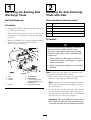
1
RemovingtheExistingSide
DischargeChute
NoPartsRequired
Procedure
1.DisengagethePTO,settheparkingbrake,andchock
orblockthedrivewheels.
2.Turnofftheengine,removethekey,andwaitforall
movingpartstostopbeforeleavingtheoperating
position.
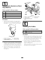
3.Removethelocknut,bolt,springandspacerholding
thedeectortothepivotbrackets(Figure1).
Removethegrassdeector.
Figure1
1.Bolt
5.Springinstalled
2.Spacer6.GrassDeector
3.Locknut
7.Lendofspring,place
behinddeckedgebefore
installingbolt
4.Spring8.Jhookendofspring
2
InstallingtheSideDischarge
ChutewithGate
Partsneededforthisprocedure:
1
Sidedischargechute
1
Bolt,(5/16x7–1/2inches)
1
Locknut,(5/16inch)
1Plasticspacer
1
Spring
Procedure
Anuncovereddischargeopeningcouldallow
thelawnmowertothrowobjectsinthe
operator’sorbystander’sdirectionandresult
inseriousinjury.Also,contactwiththeblade
couldoccur.
•Neveroperatethelawnmowerunlessyou
installacoverplate,amulchplate,oragrass
chuteandcatcher.
•Makesurethegrassdeectorisinthedown
position.
Note:Ensurethegrassdeectorisinstalledinthe
lowerholesinthemowerdeckbrackets.
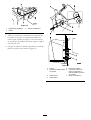
1.Placethenewspacerandspringontograssdeector.
Placeoneendofspringbehinddeckedge.
Note:Makesuretheendofthespringisinstalled
behindthedeckedgebeforeinstallingtheboltas
showninFigure2.
2.Installboltandnutinthelowerhole.Placetheend
ofthespringaroundthegrassdeector(Figure2).
3.Tightenthenutuntiltheendoftheboltisushwith
theendofthenut.Donotovertighten.
Important:Thegrassdeectormustbeableto
lowerdownintoposition.Liftthedeectorup
totestthatitlowersintothefulldownposition.
2

Figure2
1.Bolt
4.Spring
2.Spacer5.Springinstalled
3.Locknut
6.GrassDeector
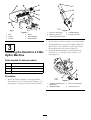
3
InstallingtheHandletoaT-Bar
HydroMachine
Partsneededforthisprocedure:
1Handleassembly
4
Bolt,(1/4x3/4inches)
4
Locknut(1/4inch)
1Bracket
Procedure
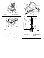
1.Installthehandleassemblytotheanglebracket
with2bolts(1/4x3/4inches)and2locknuts(1/4
inch)(Figure3).Ensuretousethecorrectbracket.
Figure3
1.Bolt(1/4x3/4inches)
3.Handleassembly
2.Bracket,ensurethe
correctoneshownisused
4.Locknut(1/4inch)
2.Checkifthereareholesexistingtomountthehandle.
3.Ifneeddrillholestomountthehandle.Markand
drill2holes,9/32indiameter,ontherightsideof
themachinebelowthecontrols(Figure4).
4.Installthehandleassemblytothemachinewith
2bolts(1/4x3/4inches)and2locknuts(1/4
inch)(Figure4).
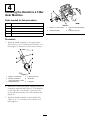
Figure4
1.Ifneeded,drillholeshere
(9/32india.)
3.Bolt(1/4x3/4inches)
2.Handleassembly
4.Locknut(1/4inch)
3

4
InstallingtheHandletoaT-Bar
GearMachine
Partsneededforthisprocedure:
1Handleassembly
2
Bolt,(1/4x1-3/4inches)
2
Bolt,(1/4x3/4inches)
4
Locknut(1/4inch)
1Bracket
Procedure
1.Installthehandleassemblytotheanglebracket
with2bolts(1/4x3/4inches)and2locknuts(1/4
inch)(Figure5).Ensuretousethecorrectbracket.
Figure5
1.Bolt(1/4x3/4inches)4.Locknut(1/4inch)
2.Bracket,ensurethe
correctoneshownisused
5.Shortside
3.Handleassembly6.Longside
2.Drillholestomountthehandle.Usingthebracketas
atemplate,markanddrill2holes,9/32indiameter,
ontherightsideofthehandle.Centertheholes
onthetubeandoneithersideofthereferencebar
(Figure4).
3.Installthehandleassemblytothemachinewith
2bolts(1/4x1-3/4inches)and2locknuts(1/4
inch)(Figure6).
Figure6
1.Bolt(1/4x1-3/4inches)3.Drilltwoholeshere(9/32in
dia.)
2.Handleassembly
4.Locknut(1/4inch)
4

5
InstallingtheHandletoaPistol
GripMachine
Partsneededforthisprocedure:
1Handleassembly
2
Bolt,(1/4x1-3/4inches)
2
Bolt,(1/4x3/4inches)
4
Locknut(1/4inch)
1Bracket
Procedure
1.Installthehandleassemblytotheanglebracket
with2bolts(1/4x3/4inches)and2locknuts(1/4
inch)(Figure7).Ensuretousethecorrectbracket.
Figure7
1.Bolt(1/4x3/4inches)
3.Handleassembly
2.Bracket,ensurethe
correctoneshownisused
4.Locknut(1/4inch)
2.Drillholestomountthehandle.Usingthebracketas
atemplate,markanddrill2holes,9/32indiameter,
ontherightsideofthehandle.Centertheholeson
thetubeandjustbelowthecontrolpanel(Figure4).
3.Installthehandleassemblytothemachinewith
2bolts(1/4x1-3/4inches)and2locknuts(1/4
inch)(Figure8).
Figure8
1.Bolt(1/4x1-3/4inches)4.Locknut(1/4inch)
2.Handleassembly
5.Controlpanel
3.Drilltwoholeshere(9/32in
dia.)
6
InstallingtheCables
Partsneededforthisprocedure:
2Plasticties
2Adhesivebackmount
Procedure
1.Routethecablesfromthedischargechutetotherear
ofthemachineontopoftheengineplatformand
alongtherightsideoftheengine.Ensurethecables
passunderanyhydrauliclinesandfuellines.
2.Fastenthecablestotheenginedeckandmower
deckwithaplastictiesandadhesivebackmounts
(Figure9andFigure10).
Ensurethecablesdonotinterferewiththereartires,
themuferandanymovingparts.
5

Figure9
1.Cables
2.Plasticcabletie
Figure10
1.Plasticcabletie3.Adhesivebackmount
2.Cables
3.Loosenthelocknutandinsertthecableends
betweenthepulley.Itisimportanttoinstallthe
cablesasshowninFigure11.Thiswillensurethe
chuteoperatesasshownintheOperationSection.
4.Installthecableintotheslotandthenpushthe
plasticretainerintothehole(Figure11).
Figure11
1.Handle
5.Chutegate
2.Endofcable,install
betweenpulley
6.Installcableintoslotand
thenpushplasticretainer
intohole
3.Insidecable7.Loosenlocknut
4.Outsidecable
6

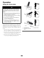
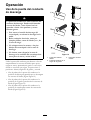
Operation
UsingtheChuteGate
Thechutegatedoesnotsealthedischarge
opening.Grassandobjectsmaybethrownin
abystander’sdirectionandresultinserious
injury.
•Beawareofthemowerdischargedirection
anddonotpointitatanyone.
•Removeobstaclessuchasrocks,treelimbs,
etc.fromthemowingarea.
•Neverputyourhandsorfeetunderthe
mowerordischargearea.
•Nevertrytoclearthedischargeareaor
mowerbladesunlesstheengineisoffand
thekeyisremoved.
Usethechutegatetotemporarilystopordeectgrass
clippingsawayfromsidewalks,parkinglots,patios,or
anywhereyoudonotwantgrassclippingstoland.The
chutegatehas3positions:open,45degreeangle,and
closed.
•Rotatethechutegatehandletotheopenpositionto
allowgrassclippingstodischarge(FigureFigure12).
•Rotatethechutegatehandletothe45degreeangle
todeectthegrassclippings(FigureFigure12).
•Rotatethechutegatehandletotheclosedposition
tostopthegrassclippings(FigureFigure12).
Figure12
1.Chutegateopen3.Chutegateclosed
2.Chutegateat45degree
angle
7

FormNo.3361-286RevA
Kitdepuertadelconductodedescarga
Cortacéspedesdirigidosdetamañomedio
Nºdemodelo115–4190
Nºdemodelo115–4195
Instruccionesdeinstalación
Instalación
Piezassueltas
Utilicelatablasiguienteparavericarquenofaltaningunapieza.
Procedimiento
DescripciónCant.
Uso
1
Nosenecesitanpiezas
–
Retirarelconductodedescargalateral
actual.
Conductodedescargalateral
1
Perno,(5/16x7-1/2pulg.)
1
Contratuerca,(5/16inch)
1
Espaciadordeplástico1
2
Muelle1
Instalarelconductodedescargalateral
conpuerta.
Conjuntodelmanillar
1
Perno,(1/4x3/4pulg.)
4
Contratuerca(1/4inch)
4
3
Soporte
1
Instalarlapalancaenunamáquina
T-Barcontransmisiónhidrostática
Conjuntodelmanillar
1
Perno(1/4x1-3/4pulgadas)
2
Perno,(1/4x3/4pulg.)
2
Contratuerca(1/4inch)
4
4
Soporte
1
Instalarlapalancaenunamáquina
T-Barcontransmisióndeengranajes
Conjuntodelmanillar
1
Perno(1/4x1-3/4pulgadas)
2
Perno,(1/4x3/4pulg.)
2
Contratuerca(1/4inch)
4
5
Soporte
1
Instalarlapalancaenunamáquinacon
empuñadurastipopistola
Sujetacablesdeplástico
2
6
Soporteautoadhesivo
2
Instalarloscables.
©2008—TheToro®Company
8111LyndaleAvenueSouth
Bloomington,MN55420
Registresuproductoenwww.Toro.com.
Traduccióndeloriginal(ES)
ImpresoenEE.UU.
Reservadostodoslosderechos

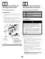
1
Retiradadelconductode
descargalateralactual
Nosenecesitanpiezas
Procedimiento
1.Desengranelatomadefuerza,pongaelfreno
deestacionamientoycalceobloqueelasruedas
motrices.
2.Pareelmotor,retirelallaveyespereaquese
detengantodaslaspiezasenmovimientoantesde
abandonarelpuestodeloperador.
3.Retirelacontratuerca,elperno,elmuelleyel
espaciadorquesujetaneldeectoralossoportesde
pivote(Figura1).Retireeldeectordehierba.
Figura1
1.Perno5.Muelleinstalado
2.Espaciador
6.Deectordehierba
3.Contratuerca
7.ExtremoLdelmuelle;
coloquedetrásdelreborde
delaplataformaantesde
instalarelperno
4.Muelle8.ExtremoenJdelmuelle
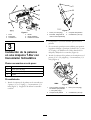
2
Instalacióndelconductode
descargalateralconpuerta
Piezasnecesariasenestepaso:
1
Conductodedescargalateral
1
Perno,(5/16x7-1/2pulg.)
1
Contratuerca,(5/16inch)
1Espaciadordeplástico
1Muelle
Procedimiento
Sielhuecodedescargasedejadestapado
elcortacéspedpodríaarrojarobjetoshacia
eloperadorohaciaotraspersonasycausar
lesionesgraves.Tambiénpodríaproducirseun
contactoconlacuchilla.
•Nooperenuncaelcortacéspedsintener
instaladounatapa,unaplacadepicadooun
conductodehierbaybolsaderecortes.
•Compruebequeeldeectordehierbaestá
bajado.
Nota:Asegúresedequeeldeectordehierbaestá
instaladoenlostaladrosinferioresdelossoportesdela
plataformadelcortacésped.
1.Coloqueelespaciadoryelmuellenuevoenel
deectordehierba.Coloqueunextremodelmuelle
detrásdelrebordedelaplataforma.
Nota:Asegúresedecolocarelextremoendel
muelledetrásdelrebordedelaplataformaantesde
instalarelperno,segúnsemuestraenFigura2.
2.Instaleelpernoylatuercaeneltaladroinferior.
Coloqueelextremodelmuellealrededordel
deectordehierba(Figura2).
3.Aprietelatuercahastaqueelextremodelpernoesté
enrasadoconelextremodelatuerca.Noapriete
excesivamente.
Importante:Eldeectordehierbadebepoder
bajarasuposición.Levanteeldeectorpara
vericarquepuedebajardeltodo.
2

Figura2
1.Perno4.Muelle
2.Espaciador5.Muelleinstalado
3.Contratuerca6.Deectordehierba
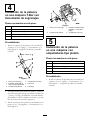
3
Instalacióndelapalanca
enunamáquinaT-Barcon
transmisiónhidrostática
Piezasnecesariasenestepaso:
1
Conjuntodelmanillar
4
Perno,(1/4x3/4pulg.)
4
Contratuerca(1/4inch)
1
Soporte
Procedimiento
1.Instaleelconjuntodelapalancaenlaescuadracon
2pernos(1/4x3/4pulg.)y2contratuercas(1/4
inch)(Figura3).Asegúresedeutilizarlaescuadra
correcta.
Figura3
1.Perno(1/4x3/4pulg.)3.Conjuntodelapalanca
2.Escuadra;asegúresede
usarlacorrecta(ilustrada)
4.Contratuerca(1/4inch)
2.Compruebesiyaexistentaladrosparamontarla
palanca.
3.Siesnecesario,practiqueunostaladrosparamontar
lapalanca.Marqueypractique2taladrosde7,1mm
(9/32pulg.)dediámetroenelladoderechodela
máquina,debajodeloscontroles(Figura4).
4.Instaleelconjuntodelapalancaenlamáquinacon2
pernos(1/4x3/4pulgadas)y2contratuercas(1/4
inch)(Figura4).
Figura4
1.Siesnecesario,practique
lostaladrosaquí(diámetro
7,1mm[9/32pulg.])
3.Perno(1/4x3/4pulg.)
2.Conjuntodelapalanca4.Contratuerca(1/4inch)
3

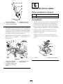
4
Instalacióndelapalanca
enunamáquinaT-Barcon
transmisióndeengranajes
Piezasnecesariasenestepaso:
1
Conjuntodelmanillar
2
Perno(1/4x1-3/4pulgadas)
2
Perno,(1/4x3/4pulg.)
4
Contratuerca(1/4inch)
1
Soporte
Procedimiento
1.Instaleelconjuntodelapalancaenlaescuadracon
2pernos(1/4x3/4pulg.)y2contratuercas(1/4
inch)(Figura5).Asegúresedeutilizarlaescuadra
correcta.
Figura5
1.Perno(1/4x3/4pulg.)4.Contratuerca(1/4inch)
2.Escuadra;asegúresede
usarlacorrecta(ilustrada)
5.Ladocorto
3.Conjuntodelapalanca
6.Ladolargo
2.Practiquetaladrosparamontarlapalanca.Usandola
escuadracomoguía,marqueypractique2taladrosde
7,1mm(9/32pulg.)dediámetroenelladoderecho
delmanillar.Centrelostaladroseneltuboyencada
ladodelabarradereferencia(Figura4).
3.Instaleelconjuntodelapalancaenlamáquinacon2
pernos(1/4x3/4pulgadas)y2contratuercas(1/4
inch)(Figura6).
Figura6
1.Perno(1/4x1-3/4pulg.)
3.Practiquelostaladrosaquí
(diámetro7,1mm[9/32
pulg.])
2.Conjuntodelapalanca4.Contratuerca(1/4inch)
5
Instalacióndelapalanca
enunamáquinacon
empuñadurastipopistola
Piezasnecesariasenestepaso:
1
Conjuntodelmanillar
2
Perno(1/4x1-3/4pulgadas)
2
Perno,(1/4x3/4pulg.)
4
Contratuerca(1/4inch)
1
Soporte
Procedimiento
1.Instaleelconjuntodelapalancaenlaescuadracon
2pernos(1/4x3/4pulg.)y2contratuercas(1/4
inch)(Figura7).Asegúresedeutilizarlaescuadra
correcta.
4

Figura7
1.Perno(1/4x3/4pulg.)3.Conjuntodelapalanca
2.Escuadra;asegúresede
usarlacorrecta(ilustrada)
4.Contratuerca(1/4inch)
2.Practiquetaladrosparamontarlapalanca.Usandola
escuadracomoguía,marqueypractique2taladrosde
7,1mm(9/32pulg.)dediámetroenelladoderecho
delmanillar.Centrelostaladroseneltuboyjusto
pordebajodelpaneldecontrol(Figura4).
3.Instaleelconjuntodelapalancaenlamáquinacon2
pernos(1/4x3/4pulgadas)y2contratuercas(1/4
inch)(Figura8).
Figura8
1.Perno(1/4x1-3/4pulg.)4.Contratuerca(1/4inch)
2.Conjuntodelapalanca
5.Paneldecontrol
3.Practiquelostaladrosaquí
(diámetro7,1mm[9/32
pulg.])
6
Instalacióndeloscables
Piezasnecesariasenestepaso:
2
Sujetacablesdeplástico
2
Soporteautoadhesivo
Procedimiento
1.Paseloscablesdesdeelconductodedescargahasta
lapartetraseradelamáquina,porencimadela
plataformadelmotoryjuntoalladoderechodel
motor.Asegúresedepasarloscablespordebajode
cualquiermanguitohidráulicootubodecombustible.
2.Sujeteloscablesalaplataformadelmotorcon
sujetacablesdeplásticoysoportesautoadhesivos
(Figura9yFigura10).
Asegúresedequeloscablesnopuedantocarlos
neumáticostraseros,elsilenciadorocualquierpieza
móvil.
Figura9
1.Cables2.Sujetacablesdeplástico
5

Figura10
1.Sujetacablesdeplástico3.Soporteautoadhesivo
2.Cables
3.Aojelacontratuercaeintroduzcalosextremosde
loscablesenlapolea.Esimportanteinstalarlos
cablessegúnseindicaenFigura11.Deestomodo
seaseguraqueelconductofuncionesegúnseexplica
enlasecciónUso.
4.Coloqueelcableenlaranuraeintroduzcaelreténde
plásticoapresióneneloricio(Figura11).
Figura11
1.Palanca5.Puertadelconducto
2.Extremodelcable;instalar
enlapolea
6.Coloqueelcableenla
ranuraeintroduzcael
reténdeplásticoapresión
eneloricio
3.Cableinterno7.Aojelacontratuerca
4.Cableexterno
6

Operación
Usodelapuertadelconducto
dedescarga
Lapuertadelconductonosellalaaberturadel
conductodedescarga.Puedensalirlanzados
recortesdehierbayotroobjetoshaciael
operadorohaciaotraspersonasycausar
lesionesgraves.
•Estéatentoalsentidodedescargadel
cortacéspedynoorienteladescargahacia
nadie.
•Retirecualquierobstáculo,comopor
ejemplopiedras,ramasdeárboles,etc.,de
lazonadesiega.
•Nocoloquenuncalasmanosolospies
debajodelcortacéspedodelazonade
descarga.
•Nointentenuncadespejarlazonade
descargaolascuchillasdelcortacéspedsin
antespararelmotoryretirarlallave.
Utilicelapuertadelconductoparadetenerodesviar
temporalmentelosrecortesdehierbaparaqueno
caiganenaceras,aparcamientos,patiosuotrossitios
dondenoconvienequecaigan.Lapuertatiene3
posiciones:abierta,ángulode45grados,ycerrada.
•Girelapalancadelapuertadelconductoala
posicióndeabiertaparapermitirquesedescarguen
losrecortesdehierba(FiguraFigura12).
•Girelapalancadelapuertadelconductoala
posiciónde45gradosparadesviarlosrecortesde
hierba(FiguraFigura12).
•Girelapalancadelapuertadelconductoala
posicióndecerradapararetenerlosrecortesde
hierba(FiguraFigura12).
Figura12
1.Puertadelconducto
abierta
3.Puertadelconducto
cerrado
2.Puertadelconductoenun
ángulode45grados
7

Notas:
8

-
 1
1
-
 2
2
-
 3
3
-
 4
4
-
 5
5
-
 6
6
-
 7
7
-
 8
8
-
 9
9
-
 10
10
-
 11
11
-
 12
12
-
 13
13
-
 14
14
-
 15
15
-
 16
16


Toro Operator-Controlled Discharge Chute Kit, Commercial Walk-Behind Mower Guía de instalación
- Categoría
- Cortadoras de césped
- Tipo
- Guía de instalación
en otros idiomas
Artículos relacionados
-
Toro Operator-Controlled Discharge Chute Kit Guía de instalación
-
-
-
-
-
Toro TimeMaster 30in Lawn Mower Manual de usuario
-
-
Toro Lawnmower Manual de usuario