
Carretera CV-20 km.2 · 12540 Vila-real · Castellón · Spain
Tel: +34 964 50 64 50 - Fax: +34 964 50 67 93
e-mail: [email protected] · www.noken.com
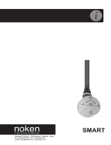
SMART ECO

2
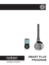
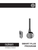
Este es un termostato electrónico para el control automático de los seca-toallas eléctricos.
ADVERTENCIA: Este aparato solo esta destinado al secado de toallas húmedas.
This is an electronic thermostat for the automatic control of electric towel radiators.
WARNING: This appliance is intended only for drying wet towels.
Cet est un thermostat électronique pour la commande de sèche-serviettes électriques.
AVERTISEMENT: Cet applareil est uniquement conçu, au séchage de serviettes mouillées
Este dispositivo é um termostato eletrónico para o controlo automático de toalheiros radiadores.
AVISO: Este aparelho destina-se apenas à secagem toalhas úmidas.
Это электронный термостат для автоматического управления электрическими полотенцесушителями
Este producto cumple con las siguientes normas:
-Eco-diseño, Directiva para productos que consumen energía, 2005/32/EC (<0,5W)
-EN 60335-1:2012+A11:2014
-EN 60335-2-30:2009+A11:2012
-EN 60335-2-43:2003+A1:2006+A2:2008
-EN 61000-3-2:2014 -EN61000-3-3:2013 -EN 62233:2008
-EN 55014-1:2006+A1:2009+A2:2011 -EN 55014-2:1997+A1:2001+A2:2008
This is compliant with the following standarts:
-Eco-design Directive for Energy-using Products, 2005/32/EC (<0,5W)
-EN 60335-1:2012+A11:2014
-EN 60335-2-30:2009+A11:2012
-EN 60335-2-43:2003+A1:2006+A2:2008
-EN 61000-3-2:2014 -EN61000-3-3:2013 -EN 62233:2008
-EN 55014-1:2006+A1:2009+A2:2011 -EN 55014-2:1997+A1:2001+A2:2008
Cet est conforme aux directives suivantes:
-Directive Écoconception pour les appareils consommateurs d’énergie, 2005/32/CE (<0,5W)
-EN 60335-1:2012+A11:2014
-EN 60335-2-30:2009+A11:2012
-EN 60335-2-43:2003+A1:2006+A2:2008
-EN 61000-3-2:2014 -EN61000-3-3:2013 -EN 62233:2008
-EN 55014-1:2006+A1:2009+A2:2011 -EN 55014-2:1997+A1:2001+A2:2008
Este produto cumpre as normas seguintes:
-Diretiva de conceção ecológica dos produtos consumidores de energia (2005/32/CE) (<0,5 W)
-EN 60335-1:2012+A11:2014
-EN 60335-2-30:2009+A11:2012
-EN 60335-2-43:2003+A1:2006+A2:2008
-EN 61000-3-2:2014 -EN61000-3-3:2013 -EN 62233:2008
-EN 55014-1:2006+A1:2009+A2:2011 -EN 55014-2:1997+A1:2001+A2:2008
Продукт соответствует следующим стандартам:
-Директива по эко-дизайну для энергосберегающих продуктов,, 2005/32/EC (<0,5W)
-EN 60335-1:2012+A11:2014
-EN 60335-2-30:2009+A11:2012
-EN 60335-2-43:2003+A1:2006+A2:2008
-EN 61000-3-2:2014 -EN61000-3-3:2013 -EN 62233:2008
-EN 55014-1:2006+A1:2009+A2:2011 -EN 55014-2:1997+A1:2001+A2:2008
Este es un producto certicado:
This is a certied product:
Cest est un produit certié:
Este produto possui certicação:
Это сертифицированный продукт:

3
Modos de operación: Calentamiento continuo, Stand-by, Boost, Timer12, Timer24
• Modo “Calentamiento contínuo”: el control electrónico activa el elemento calefactor y se mantiene activo hasta que el usuario decide ajustar
el dispositivo al modo “Standby”.
• Modo “Boost”: el termostato alimenta el elmento calefactor a la máxima potencia, durante 2 hs. Al nal de las 2 hs, el control vuelve de nuevo
al modo “Standby”.
• Modos “Timer12” y “Timer24”: el control electrónico active la función “Boost” por 2 hs. Una vez nalizadas, el control entra en “Standby”
durante o bien 10 o 22 hs (el usuario tiene la posibilidad de preajustarlo), despues de ello el termostato repite la función “Boost” durante 2 hs.
Esta secuencia se repite sinn
• Modo “Standby”: activando esta función, el dispositivo entra en “Standby” y el elemento calefactor se desactiva
Operative modes: Continuous-Heating, Stand-by, Boost, Timer12, Timer24
• “Continuous-Heating”: the electronic control activates the heating element and remains active until the user decides to set the device in “Stand-
by” mode.
• “Boost” mode: the thermostat feeds the heating element at the maximal power for two hours. At the end of the two hours, the control goes back
into the “Stand-by” mode.
• “Timer12” and “Timer 24” mode: the electronic control activates the “Boost” function for two hours. At the end of the two hours the control
enters into “Stand-by” mode for either 10 or 22 hours (the user has the possibility to preset it), after which the thermostat repeats the function
“Boost” for two hours. This sequence is repeated cyclically
• “Stand-by” mode: by activating this function, the device goes in stand-by, the heating element is deactivated.
Modes de fonctionnement: Chauage continu, Veille, Boost, Timer12 et Timer24
• ”Chauage continu”: la commande électronique active l’élément chauant et reste active jusqu’à ce que l’utilisateur règle l’appareil en mode
“Veille”
• Mode “Boost”: le thermostat active l’élément chauant à la puissance maximale pendant deux heures. Une fois les deux heures écoulées, la
commande revient en mode “Veille”.
• Modes “Timer12” et “Timer24” : la commande électronique active la fonction “Boost” pendant deux heures. Une fois les deux heures écoulées,
la commande passe en mode “Veille” pendant 10 heures ou 22 heures (durée préréglable par l’utilisateur), après quoi le thermostat répète la
fonction “Boost” pendant 2 heures. Cette séquence se répète cycliquement.
• Mode “Veille”: quand cette fonction est activée, l’appareil se met en veille et l’élément chauant est désactivé.
Modos de funcionamento: Continuous-Heating, Stand-by, Boost, Timer12, Timer24
• “Aquecimento contínuo”: o controlador eletrónico ativa o elemento de aquecimento, permanecendo este ativo até que o utilizador decida
ajustar o dispositivo no modo “Standby”.
• Modo “Boost”: o termostato alimenta o elemento de aquecimento à máxima potência durante 2 horas. Decorridas estas 2 horas, o controlador
retorna ao modo “Standby”•Modo “Timer”: o sistema de controlo entra no modo “Boost” durante 2 horas; em seguida, volta ao modo “Comfort”
por 22 ou 10 horas (período congurável pelo utilizador) e depois entra novamente em modo “Boost” durante 2 horas. Esta sequência repete-se
indenidamente.
• Modos “Timer12” e “Timer24”: o controlador eletrónico ativa a função “Boost” durante 2 horas. Decorrido este período, o controlador entra
em “Standby” durante 10 ou 22 horas (o utilizador pode proceder ao seu pré-ajuste); ndo este período, o termostato repete a função “Boost”
durante 2 horas. Esta sequência repete-se indenidamente.
• Modo “Standby”: com a ativação desta função, o dispositivo entra em “Standby” e o elemento de aquecimento é desativado
Оперативные режимы: непрерывное нагревание, режим ожидания, режим ускорения(Boost), таймер12, таймер24
Режим “Непрерывное нагревание”: электронное управление активирует нагревательный элемент и он остается активным до тех пор,
пока пользователь не решит установить устройство в режим ожидания.
• Режим “Boost”: термостат использует нагревательный элемент при максимальной мощности в течение двух часов. По истечении двух
часов, устройство возвращается в режим «Stand-by».
• Режим “Timer12” и “Timer 24”: электронное управление активирует режим «Boost» в течение двух часов. По истечении двух часов
управление переходит в режим «Stand-by» в течение 10 или 22 часов (у пользователя есть возможность его предустановить), после чего
термостат повторяет функцию «Boost» в течение двух часов. Эта последовательность повторяется циклически
• Режим “Stand-by”: при активации этой функции, устройство переходит в режим ожидания, нагревательный элемент отключается.

4
Producto Control electronico de seca-toallas
Aplicaciones Radiadores seca-toallas
Clase de aislamiento Clase I, Clase II
Nivel IP IP44
Temperatura de operación -10°C ÷ 40°C
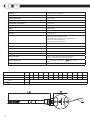
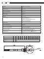
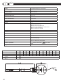
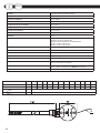
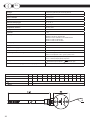
Potencia maxima Ver tabla abajo
Voltaje 230VAC 50Hz
Medidas Ver gura abajo
Garantía 2 years / 2 años
Normas aplicables -EN 60335-1:2012+A11:2014 -EN 60335-2-30:2009+A11:2012
-EN 60335-2-43:2003+A1:2006+A2:2008
-EN 61000-3-2:2014 -EN61000-3-3:2013 -EN 62233:2008
-EN 55014-1:2006+A1:2009+A2:2011
-EN 55014-2:1997+A1:2001+A2:2008
Marcado CE
Caja ABS-VO
Directiva medioambiental WEEE, RoHS
Modos de operación Calentamiento continuo, Boost2h, Timer12h, Timer24h,Stand-by
Indicadores del estado del termostato Boost/Timer led (rojo, verde, ambar) On/off led (rojo),
Conexión a la red Clase I - 3 cables (neutro, fase, tierra); Enchufe Europeo
Clase II - 2 Cables (neutro, fase); Enchufe Europeo
Colores disponibles Blanco; Cromo; Negro // Blanco; Cromo;
Temperatura maxima del fusible termico 152°C
ESP
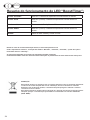
Potencia (W) 100 200 250 300 400 500 600 700 750 800 900 1000
L (resistencia) class II (mm) 350 350 350 350 370 410 465 520 560 600 670 730
L (resistencia) class I (mm) 350 350 370 370 430 450 560 630 700 700 760 830
* (mm) 1200
* (mm) 500-1000
*

5
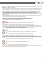
ATENCIÓN
RIESGO DE ELECTROCUCIÓN
Desconectar la corriente antes de proceder a la instalación
Conservar debidamente la presente hoja de instrucciones y leerla atentamente antes de
utilizar el dispositivo:
•Este dispositivo se ha diseñado para el uso exclusivo en un radiador seca-toallas
•El termostato está diseñado para calentar el líquido contenido dentro del seca-toallas
en combinación con un elemento calefactor. Se prohibe cualquier otro uso.
•Antes de usarlo, asegurarse que la linea de voltaje es la misma que el especicado para
el dispositivo (ver el apartado de características técnicas)
•Usar solo elementos calefactores compatibles con el tipo de seca-toallas
•Desconectar la corriente eléctrica siempre antes de operaciones de limpieza o de
mantenimiento.
•En caso de haber daños en el cable de corriente, desconectar el dispositivo y no
manipularlo. Los cables dañados solo pueden ser reemplazados por el fabricante o
un servicio de asistencia técnica autorizado. En caso de no seguir estas reglas podría
comprometer la seguridad del sistema e invalidar la garantía.
•Guardar y transportar el elemento calefactor exclusivemente en su caja de protección.
•El reemplazo del elemento calefactor solo puede ser efectuado por el fabricante o un
servicio técnico autorizado.
•Niños menores de 8 años y personas con capacidades sicas, sensoriales o mentales
reducidas, solo pueden usar el dipositivo bajo supervision. Los niños no deben jugar
con el dispositivo.
•La limpieza y mantenimiento a realizar por el usuario, no deben realizarse por niños sin
supervision de un adulto.
ESP

6
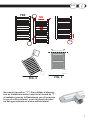
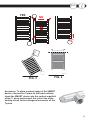
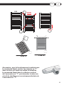
Guía de montaje. (Solo para el instalador)
1) Insertar el elemento calefactor en el oricio roscado de la parte inferior del
radiador
2) Fijar bien la Resistencia electrica al cuerpo del radiador seca-toallas con una
llave ja de 22mm
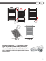
3) El “roscado especial” asegura un montaje seguro y eventualmente permite
una ligera torsion suplementaria para poder alinear el termostato con el radiador.
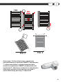
4) Ladear el radiador como en la gura 3, asegurándose que el oricio abierto
en el radiador está localizado en la parte más alta. ATENCION: No apoyar el
radiador sobre el elemento calefactor!
5) Llenar el radiador con el liquido especíco (glicol)
6) Poner el radiador de nuevo en posición vertical y ver el nivel de liquid en el
interior (g. 4)
7) Asegurarse de que el elemento calefactor está bien roscado al radiador (no
hay fugas de liquido)
8) Conectar el dispositivo a la toma de corriente y comenzar a calendar (la parte
de arriba del radiador debe permanecer abierta, es decir, el purgador)
9) Ajustar a la temperature maxima y revisar el nivel de liquido en el interior.
Debido a la expansion térmica el liquido podría salir y derramarse sobre el
radiador.
10) Quitar el exceso de liquido (tener cuidado para evitar quemaduras), para
que no se moje el termostato y evitar que el liquido alcance el borde. Cuando el
nivel de liquido deje de subir, esperar 5 minutos más y dejar de calendar.
11) Si es necesario, volcar un poco el radiador antes que el liquido se enfríe
(mantener revisada la temperatura del liquido interior en todo momento).
12) Cerrar la parte superior del radiador con el tapón y el purgador asegurándose
que son estancos.
13) Fijar el radiador seca-toallas a la pared.
14) Conectar el termostato a la corriente. Para los modelos sin enchufe, es
necesario instalar el interruptor omnipolar adecuado, asegurando que haya
una desconexión complete en caso de sobretensión de categoría III (ello quiere
decir un interruptor con al menos 3mm de separación entre contactos abiertos).
Desconectar el dispositivo de la corriente electrica antes de comenzar
Proteger el dispositivo con un RCD de 30mA
ESP

7
Accesorio (racord en “T”): Para utilizar el disposi-
tivo en instalación mixta, conectar el racord en “T”
al radiador, insertar la Resistencia con el termosta-
to por el oricio inferior, y unir la tubería de retor-
no del agua caliente en el otro oricio lateral.
YES
NO
FIG. 3 FIG. 4
YES NO
ESP

8
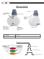
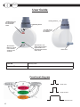
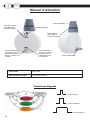
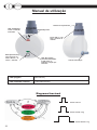
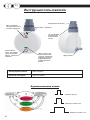
Led “On/Standby”: el
led indica el estado del
termostato
Gas 1/2” rosca
para jar el
elemento al
radiador
Resistencia
Botón “Boost/
Timer”: para selec-
cionar uno de los
modos “Boost”, “Ti-
mer12” o “Timer24”
Botón On/Standby
“Boost/Timer”:
rojo/verde/ambar
El led indica al usuario
qué función está
activa
Cable de tensión
Guía de usuario
Diagrama de funciones
Presionar una vez
Presionar durante 3 sec
presionar durante 7 sec
ESP
LED apagado Modo Stand-By
LED rojo jo El termostato esta activo

9
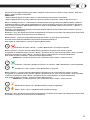
Presionar el botón [On/Standby] para conectar el dispositivo o para activar el modo “Stand-by” ; durante el
modo “Stand-by”, todos los leds están apagados.
NOTA: Cuando el dispositivo entra en modo “Stand-by”, suena “beep” dos veces por 0,5 segundos. Cuando el
dispositivo está conectado en modo “On” (ej. Está conectado), suena “beep” una vez por 1 segundo.
Modo de “calentamiento contínuo”: es posible activar esta función con el botón [ON/Standby], el elemento ca-
lefactor se activa y permanence así (calentando el radiador) hasta que la función se desactiva con el botón [ON/
Stand-by]. En este modo es possible activar las funciones “Boost”, “Timer12” e “Timer24”.
Nota: la temperatura máxima alcanzable depende de la potencia de la resistencia (ver las especicaciones
técnicas).
Nota: por motivos de seguridad la temperatura será regulada a una temperatura de seguridad para evitar un
sobrecalentamiento, dependiendo de la potencia de la resistencia.
Modo “Boost”: Presionar el botón [Boost/Timer] para activar este modo operativo.
Este modo activa el elemento calefactor a la máxima potencia por 2 hs
Para salir del modo “Boost” presionar el botón [Boost/Timer]
Indicación modo “Boost”: el led “Boost/Timer” tiene color rojo y parpadea
Modo “Timer24”: Presionar el botón [Boost/Timer] por 3 segundos para activar este modo.
El Sistema de control activa el modo “Boost” mode por 2 horas, tras ello vuelve al modo “Stand-by” y después
de 22hs el modo “Boost” se active de nuevo por 2hs. Esta secuencia se activa sinn.
Para salir del modo “Timer24” presionar el botón [Boost/Timer]
NOTA: Durante el primer ciclo la duración del modo “Stand-by” es de 21 hs
“Timer24” indicación durante 2hs “Boost”: Led “Boost/Timer” parpadeando en verde
Durante 22hs “Stand-by”: “Boost/Timer” en color verde jo
Modo “Timer12”: Presionar el botón [Boost/Timer] por más de 5 segundos para activarla.
El sistema de control activa el modo “Boost” por 2 horas, tras ello regresa al modo “Stand-by” y tras 10 horas
el modo “Boost” se conecta de nuevo por 2 hs. Esta secuencia se repite sinn
NOTA: Durante el primer ciclo la duración del modo “Stand-by” es de 9 hs
Modo Timer12 (boost 2h): Led Boost/Timer en ambar que parpadea
Modo “Stand-by” (10h): luz ja ambar del led Boost/Timer
Nota: Por motivos de seguridad la temperatura máxima del radiador durante las 2 hs del ciclo “Boost” es regu-
lada para evitar un calentamiento excesivo, dependiendo de la potencia de la resistencia
ESP

10
Resumen funcionamiento led “Boost/Timer”:
Parpadeo rojo Boost activo. El elemento calefactor se activa por 120 min
Parpadeo verde Boost activo (Timer24). El elemento calefactor se activa por 120 min
Verde jo Regreso al modo “Standby” por 22hs
Parpadeo ambar Boost activo (Timer12). El elemento calefactor se active por 120 minutos
Ambar jo Regreso al modo “stand-by” por 10 hs”
Notas:
En caso de interrupción del suministro eléctrico el termostato se queda en modo “calentamiento continuo”, con la excep-
ción de los modos: “Boost2h”, “Timer12h”, “Timer24h”, de los que el termostato regresa a “Stand-by”
Reparaciones llevadas a cabo por personal no autorizado invalidan la garantía.
El fabricante/vendedor se reserva el derecho a realizar cualquier cambio en el producto descrito en este manual, en cual-
quier momento, y sin previo aviso.
DESECHADO:
Este producto no debe tratarse como desechos communes del hogar. Se debe eliminar en los lugares
de recogida adecuados. En caso de reemplazo se debe devolver al vendedor.
Los tratamientos adecuados al nal del ciclo de vida de este producto conservarán el medio ambiente
y reducirán el consumo de recursos de la naturaleza.
Este símbolo aplicado al presente producto indica la obligación de llevarlo a un lugar de recogida de
residuos apropiado, con objeto de desecharlo de acuerdo a las directivas 2002/96 / CE (RAEE- WEEE).
ESP

11
ESP

12
Product Electronic control for towel radiators
Applications Towel radiators
Insulation class Class I, Class II
IP level IP44
Operational temperature -10°C ÷ 40°C
Maximal power See table below
Supply voltage 230VAC 50Hz
Size See gure below
Warranty 2 years / 2 años
Standards -EN 60335-1:2012+A11:2014
-EN 60335-2-30:2009+A11:2012
-EN 60335-2-43:2003+A1:2006+A2:2008
-EN 61000-3-2:2014 -EN61000-3-3:2013 -EN 62233:2008
-EN 55014-1:2006+A1:2009+A2:2011
-EN 55014-2:1997+A1:2001+A2:2008
Approval mark CE
Case ABS-VO
Environmental directive WEEE, RoHS
Operative modes Comfort, Boost2h, Timer12h, Timer24h, Antifreeze/Standby, Key- lock.
Thermostat status indicators Boost/Timer LED (red/green/amber)
Comfort Bar with 6 LEDs: 1 blue, 1 green, 2 yellows, 2 reds
Connection to mains Class I - 3 Cables (neutral, line, earth); European Plug
Class II - 2 Cables (neutral, line); European Plug
Available colours White; Chrome; Black // White; Chrome
Maximal temperature of the thermal fuse 152°C
ENG
*
Potencia (W) 100 200 250 300 400 500 600 700 750 800 900 1000
L (heathing element) class II (mm) 350 350 350 350 370 410 465 520 560 600 670 730
L (heathing element) class I (mm) 350 350 370 370 430 450 560 630 700 700 760 830
* (mm) 1200
* (mm) 500-1000

13
WARNING
RISK OF ELECTRIC SHOCK!
Disconnect power supply before proceeding with installation
Preserve with care the present instruction sheet and read carefully before using the
device.
•The present device has been designed for exclusive use on a towel radiator.
•The thermostat is designed for heating the liquid contained inside a towel radiator in
combination with a heating element. Any other use is forbidden.
•Before using, carefully ensure that the line voltage is the same as that specied for the
device (see technical specications).
•Only use heating elements compatible with the type of used towel radiator.
•Disconnect power supply before cleaning or before performing maintenance of the
product.
•In case of damage of the power supply cable shut down the device and do not tamper with
it. The damaged power supply cables can be replaced exclusively by the manufacturer
or by an authorized service center. Failure to comply with the above rules could lead to
compromised system safety and void the warranty.
•Store and transport the heating element exclusively in the protecting packaging.
•Replacement of the heating element can be done exclusively by the product manufacturer.
•Children aged under 8 years old and people with reduced physical, sensory or mental
abilities, can use the device only under supervision. Children should not play with the
device.
•Cleaning and maintenance meant to be carried out by the user should not be done by
children without supervision.
ENG

14
Installation Guide. (To be used by installer only)
1) Insert the heating element in the threaded opening located on the bottom part
of the radiator.
2) Securely fasten the electric resistance to the body of the towel radiator with
a 22mm wrench.
3) The special sheath ensures a secure mounting and eventually allows a slight
supplemental torsion to perfectly align the thermostat with the radiator.
4) Tilt the radiator as in g. 3, making sure that the opening on top of the
radiator is located on the highest side. WARNING. Do not lean the radiator on
the electronic control!
5) Fill the radiator with the specic liquid.
Llenar el radiador con el liquido especíco (glicol)
6) Put the radiator back in vertical position and check the internal level of the
liquid (g. 4).
7) Ensure a proper fastening of the heating element in the radiator.
8) Connect the device to mains and start heating (the top opening of the radiator
must remain open!).
9) Set the maximal temperature and check the level of the internal liquid. Due to
thermal expansion the liquid could brim over the radiator.
10) Remove the exceeding liquid (be careful to avoid burns!) in order to keep the
thermostat dry and avoid the liquid reaching the border. When the level of the
liquid stops growing wait for additional 5 minutes then stop heating.
11) If necessary, top up the radiator before the liquid cools down (keep the
temperature of the internal liquid checked all the time).
12) Close the top opening of the radiator with the appropriate cap.
13) Hook the radiator to the wall.
14) Connect the device to the mains. For models having no plug it is necessary
to install a suitable omnipolar disconnection switch ensuring complete
disconnection in case of category III overvoltage (that means a switch with at
least 3 mm of space between open contacts).
Disconnect the device from power supply before proceeding with installation.
Protect the device with a 30mA RCD circuit breaker
ENG

15
YES
NO
FIG. 3 FIG. 4
Accessory: To allow a mixed usage of the SMART
device, connect the T-piece to the towel radiator,
insert the SMART device into the vertical manifold
of the T- piece and connect the return line of the
heating circuit to the orthogonal connector of the
T-piece
YES NO
ENG

16
User Guide
Functional diagram
Press once
Press for 3sec
Press for 7sec
ENG
“On/Stand-by” led:
the led indicates
the thermostat
status
1/2” GAS thread
for fastening on
the radiator
Heating element
“Boost/Timer”
Button: To select
one of “Boost”,
“Timer12” and
“Timer24”
On/Standby button
“Boost/Timer” Led:
Small red/green/amber
light indicator to in-
form about the current
active mode Power cord
LED o Stand-By mode
Red lit LED The thermostat is active

17
ENG
Press the [On/Stand-by] button to power on the device or to activate the “Stand-by” mode; during the “Stand-
by” mode, all led are o.
NOTE: When the device enters the “Stand-by” mode, it beeps twice for 0,5 seconds. When the device is swit-
ched to “On” mode (i.e. it is switched on), it beeps once for 1sec.
“Continuous-heating” mode: it is possible to activate this function through the [ON/Stand-by] button, the hea-
ting element is activated and remains active (hence heating the towel radiator) until the function is deactivated
through the [ON/Stand-by] button. From this mode it is possible to activate the functions: “Boost”, “Timer12” e
“Timer24”.
Note: the maximal reachable temperature depends on the power of resistance (see technical specications).
Note: For safety reasons the temperature will be regulated to a safe temperature to avoid excessive overhea-
ting, depending on the power of the resistance
“Boost” mode: Press the [Boost/Timer] button to activate this operative mode. This mode activates the heating
element to the maximum power for 2hrs.
To exit the “Boost” mode press the [Boost/timer] button.
“Boost” mode indication: “Boost/Timer” LED has red color and it blinks
“Timer24” mode: Press the [Boost/Timer] button for 3 seconds to activate this mode.
The control system activates the “Boost” mode for 2 hours, after that it returns into “Stand-by” mode and after
22 hours the “Boost” mode is started again for 2 hours. This sequence will repeat endlessly.
To exit the “Timer24” mode press the [Boost/Timer] button.
NOTE: During the rst cycle the duration of the “Stand-by” mode is of 21 hours
“Timer24” indication during 2hrs “Boost”: “Boost/Timer” LED blinking green
During 22hrs “Stand-by”: “Boost/Timer” LED permanent green
“Timer12” mode: Press the [Boost/Timer] button for more than 5 seconds to activate it. The control system ac-
tivates the “Boost” mode for 2 hours, after that it returns into “Stand-by” mode and after 10 hours the “Boost”
mode is started again for 2 hours. This sequence will repeat endlessly. To exit the “Timer12” mode press the
[Boost/Timer] button.
NOTE: During the rst cycle the duration of the “Stand-by” mode is of 9 hours
Timer12 mode (boost 2h): Boost/Timer led amber and blinking
“Stand-by” mode (10h): Boost/Timer lit and amber
Note: For safety reasons the temperature will be regulated to a safe temperature to avoid excessive overhea-
ting, depending on the power of the resistance.

18
Boost/Timer LED functioning summary:
Blinking red Boost active. The heating element is active for 120 minutes.
Blinking green Boost active (Timer24). The heating element is active for 120 minutes.
Permanent green Return to “Stand-by” mode for 22 hours
Blinking ambar “Boost” function active in Timer12 mode. The heating element is powered for
120 minutes.
Permanent ambar Return to “Stand-by” mode for 10 hours
NOTE: In case of interruption of the power supply the thermostat remains in “Continuous-heating” mode, with the
exception of the modes: “Boost2h”, “Timer12h”, “Timer24h”, from which the thermostat goes back into “Stand-
By”
Repairing: they must be carried out by authorized personnel in order not to void the warranty.
The manufacturer reserves the right to make any changes to the product described in this manual, at any time, and
without prior warning.
DISPOSAL
This product may not be treated as ordinary household waste. It has to be disposed in proper waste
collection sites. In case of replacement it shall be returned to the distributor.
Such an end-of-life treatment of the product will preserve the environment and will reduce consump-
tion of natural resources.
This symbol applied to the present product indicates the obligation to bring it to a proper waste co-
llection site, in order to let it be disposed according to 2002/96 / CE (RAEE - WEEE) directives.
ENG

19
ENG

20
Produit Commande électronique pour sèche-serviettes
Applications Sèche-serviettes
Classe d'isolation Classe I et classe II
Protection IP IP44
Température de service -10°C à 40°C
Puissance maximale Voir le tableau ci-dessous
Tension d'alimentation 230 VCA 50 Hz
Dimensions Voir la gure ci-dessous
Garantie 2 ans
Norme -EN 60335-1:2012+A11:2014
-EN 60335-2-30:2009+A11:2012
-EN 60335-2-43:2003+A1:2006+A2:2008
-EN 61000-3-2:2014 -EN61000-3-3:2013 -EN 62233:2008
-EN 55014-1:2006+A1:2009+A2:2011
-EN 55014-2:1997+A1:2001+A2:2008
Marquage CE
Boîtier ABS-VO
Directive environnementale DEEE, RoHS
Modes de fonctionnement Chauffage continu, Boost2h, Timer12h, Timer24h, Veille
Voyants d'état du thermostat LED Boost/Timer (rouge, verte, orange)
LED marche/arrêt (rouge)
Branchement au secteur Classe I - 3 câbles (neutre, terre, phase), EU che
Classe II - 2 câbles (neutre, phase) EU che
Couleurs disponibles Blanc, chrome; Noir // Blanc, chrome
Température maximale du fusible 152°C
FRA
*
Potencia (W) 100 200 250 300 400 500 600 700 750 800 900 1000
L (élément chauant) class II (mm) 350 350 350 350 370 410 465 520 560 600 670 730
L (élément chauant) class I (mm) 350 350 370 370 430 450 560 630 700 700 760 830
* (mm) 1200
* (mm) 500-1000

21
AVERTISSEMENT
RISQUE DE CHOC ÉLECTRIQUE
Couper l’alimentation électrique avant de procéder à
l’installation
Conserver soigneusement les présentes instructions et les lire avec attention
avant d’utiliser l’appareil.
•Le présent appareil est destiné à une utilisation sur un sèche-serviettes
uniquement.
•Le thermostat est conçu pour chauer le liquide contenu dans un sèche-
serviettes, associé à un élément chauant. Toute autre utilisation est interdite.
•Avant utilisation, s’assurer que la tension d’alimentation est la même que la
tension du thermostat (voir les caractéristiques techniques).
•Utiliser uniquement des éléments chauants compatibles avec le modèle de
sèche-serviettes utilisé.
•Couper l’alimentation électrique avant le nettoyage ou l’entretien.
•En cas d’endommagement du câble d’alimentation électrique, éteindre l’appareil
et ne pas le manipuler. Les câbles d’alimentation endommagés doivent être
remplacés uniquement par le fabricant ou par un centre d’assistance autorisé.
Le non-respect des règles ci-dessus peut compromettre la sécurité du système
et annule la garantie.
•Stocker et transporter l’élément chauant avec la commande électronique
dans leur emballage de protection uniquement.
•L’élément chauant ne doit être remplacé que par le fabricant du produit
•Le nettoyage et l’entretien devant être eectués par l’utilisateur ne doivent pas être
eectués par des enfants sans surveillance.
FRA

22
Guide d’installation . (À utiliser par l’installateur uniquement)
1) Introduire l’élément chauant dans l’ouverture letée se trouvant en bas du
sèche-serviettes.
2) Fixer solidement la résistance électrique au corps du sèche-serviettes avec
une clé de 22 mm.
3) La garniture spéciale assure un montage solide et permet une légère torsion
supplémentaire pour un alignement parfait du thermostat et du sèche-serviettes.
4) Incliner le radiateur comme indiqué dans la gure 3, en s’assurant que
l’ouverture en haut du sèche-serviettes est du côté le plus haut. AVERTISSEMENT.
Ne pas poser le sèche-serviettes sur la commande électronique !
5) Remplir le sèche-serviettes du liquide prévu.
6) Remettre le sèche-serviettes en position verticale et vérier le niveau interne
du liquide (gure 4).
7) S’assurer que le sèche-serviettes et l’unité contenant l’élément chauant
sont xés correctement.
8) Brancher l’appareil au secteur et activer le chauage (l’ouverture supérieure
du sèche-serviettes doit rester ouverte !).
9) Régler la température maximale et observer l’augmentation du niveau du
liquide. En raison de l’expansion thermique, le liquide pourrait déborder du
sèche-serviettes.
10) Supprimer le liquide en excès (avec prudence pour éviter les brûlures)
an de ne pas mouiller le thermostat et s’assurer que le liquide n’atteint pas
le bord. Quand le niveau du liquide arrête d’augmenter, attendre 5 minutes
supplémentaires puis arrêter le chauage.
11) S’il est nécessaire d’ajouter du liquide dans le sèche-serviettes, ne pas
attendre qu’il ait refroidi (contrôler en permanence la température du liquide
interne).
12) Fermer l’ouverture supérieure du sèche-serviettes au moyen du bouchon
prévu.
13) Accrocher le sèche-serviettes au mur au moyen des supports prévus.
14) Brancher le thermostat au secteur. Pour les modèles sans che, il est
nécessaire d’installer un interrupteur de déconnexion omnipolaire approprié
assurant une déconnexion complète en cas de surtension de catégorie III (c’est-
à-dire un interrupteur d’au moins 3 mm d’espace entre les contacts ouverts).
Desconectar el dispositivo de la corriente electrica antes de comenzar
Proteger el dispositivo con un RCD de 30mA
FRA

23
Accessoire : pour le fonctionnement combiné avec
la commande Smart, monter l’accessoire en “T”
dans le retour du sèche-serviettes et introduire
la commande Smart dans le collecteur vertical
de l’accessoire en “T”, puis brancher le retour du
circuit de chauage au raccord perpendiculaire de
l’accessoire en “T”.
YES
NO
FIG. 3 FIG. 4
OUI NON
FRA

24
LED “Marche/ Veille”:
cette LED indique
l’état du thermostat
Filetage GAZ 1/2’’
pour la xation
au sèche- serviettes
Élément chauant
Bouton [Boost/Timer] :
il permet de choisir l’un
des modes suivants : «
Boost », « Timer12 », «
Timer24 »
Bouton On/Standby
LED « Boost/Timer » :
rouge / verte / orange.
Une LED indique à
l’utilisateur les fonc-
tions activées Cordon d’alimentation
Manuel d’utilisation
Functional diagram
Presser une fois
Presser pendant 3 s
Presser pendant 7 s
FRA
LED éteinte Mode ”Veille”
LED allumée en rouge Le thermostat est activé

25
FRA
Presser le bouton [Marche/Veille] pour mettre l’appareil sous tension ou activer le mode « Veille ». En mode «
Veille », toutes les LED sont éteintes.
REMARQUE :
- Quand l’appareil passe en mode « Veille », il émet deux bips sonores de 0,5 secondes.
- Quand l’appareil passe en mode « Marche » (quand il est mis en marche), il émet un bip sonore d’1 s.
Mode « Chauage continu » : cette fonction peut être activée au moyen du bouton [Marche/Veille], l’élément
chauant est activé et reste activé (chauant donc le sèche-serviettes) jusqu’à ce que la fonction soit désac-
tivée au moyen du bouton [Marche/Veille]. Dans ce mode, il est possible d’activer les fonctions : « Boost », «
Timer12 » et « Timer24 ».
Remarque : la température maximale pouvant être atteinte dépend de la puissance de la résistance (voir les
caractéristiques techniques).
Remarque : pour des raisons de sécurité, la température est régulée à une valeur sans danger pour éviter toute
surchaue, en fonction de la puissance de la résistance.
Mode « Boost » : presser le bouton [Boost/Timer] pour activer ce mode de fonctionnement.
Ce mode active l’élément chauant à la puissance maximale pendant 2 h.
Pour quitter le mode « Boost », presser le bouton [Boost/Timer]
Indication du mode « Boost » : la LED « Boost/Timer » est rouge et clignote
Mode « Timer24 » : presser le bouton [Boost/Timer] pendant 3 secondes pour activer ce mode.
Le système de commande active le mode « Boost » pendant 2 heures, puis revient en mode « Veille » pendant
22 heures et repasse en mode « Boost » pendant 2 heures. Cette séquence se répète indéniment.
Pour quitter le mode « Timer24 », presser le bouton [Boost/Timer].
REMARQUE : pendant le premier cycle, la durée du mode « Veille » est de 21 heures
Indication « Timer24 » pendant le « Boost » de 2 heures : LED « Boost/Timer » verte clignotante
Pendant la « veille » de 22 h : LED « Boost/Timer » verte xe
Mode « Timer12 » : presser le bouton [Boost/Timer] pendant plus de 5 secondes pour activer ce mode.
Le système de commande active le mode « Boost » pendant 2 heures, puis revient en mode « Veille » pendant
10 heures et repasse en mode « Boost » pendant 2 heures. Cette séquence se répète indéniment.
Pour quitter le mode « Timer12 », presser le bouton [Boost/Timer]
REMARQUE : pendant le premier cycle, la durée du mode « Veille » est de 9 heures
Mode Timer12 (boost 2 h) : LED Boost/Timer orange et clignotante
Mode « Veille » (10 h) : LED Boost/Timer allumée et orange
Remarque : pour des raisons de sécurité, la température est régulée à une valeur sans danger pour éviter toute
surchaue, en fonction de la puissance de la résistance.

26
Schéma fonctionnel de la LED “Boost/Timer”:
Rouge et clignotante Le boost est activé. L’élément chauffant est activé pendant 120 minutes.
Verte et clignotante Boost activé (Timer24). L’élément chauffant est activé pendant 120 minutes.
Verte xe Revient en mode « Veille » pendant 22 heures.
Orange et clignotante Boost activé (Timer12). L’élément chauffant est activé pendant 120 minutes.
Orange xe Revient en mode « Veille » pendant 10 heures.
Remarques.
En cas d’interruption de l’alimentation électrique, le système redémarre dans le dernier mode de fonctionnement*,
sauf pour les modes « Boost » et « Timer ».
* L’état du thermostat est sauvegardé 5 secondes après la dernière modication.
Réparations : les réparations doivent être réalisées par un personnel autorisé, faute de quoi la garantie est annu-
lée.
Le fabricant se réserve le droit d’apporter à tout moment et sans préavis toutes les modications qu’il juge néces-
saires pour améliorer le produit
ÉLIMINATION
Cet appareil ne doit pas être jeté dans les ordures ménagères. Il doit être éliminé dans des points de
collecte des déchets adaptés. En cas de remplacement, il doit être retourné au distributeur. Ce traite-
ment du produit en n de vie permet de préserver l’environnement et de réduire la consommation de
ressources naturelles.
Appliqué au présent produit, ce symbole indique l’obligation de retour à un centre de collecte adapté
en vue de son élimination conformément à la directive 2002/96/CE (DEEE).
FRA

27
FRA

28
Produto Controlador eletrónico de toalheiros radiadores
Aplicações Toalheiros radiadores
Classe de isolamento Classe I, Classe II
Nível IP IP44
Temperatura de funcionamento -10 °C ÷ 40 °C
Potência máxima Ver tabela abaixo
Tensão de alimentação 230 V CA, 50 Hz
Dimensões Ver gura abaixo
Garantia 2 anos
Normas aplicáveis -EN 60335-1:2012+A11:2014 -EN 60335-2-30:2009+A11:2012
-EN 60335-2-43:2003+A1:2006+A2:2008
-EN 61000-3-2:2014 -EN61000-3-3:2013 -EN 62233:2008
-EN 55014-1:2006+A1:2009+A2:2011
-EN 55014-2:1997+A1:2001+A2:2008
Marcação CE
Caixa ABS-VO
Diretiva ambiental REEE, RoHS
Modos de funcionamento Continuous-heating, Boost2h, Timer12h, Timer24h, Stand-by
Indicadores do estado do termostato Boost/Timer led (red, green, amber) On/off led (red),
Ligação à alimentação elétrica Classe I - 3 os (neutro, fase, terra); EU cha
Classe II - 2 os (neutro, fase); EU cha
Cores disponíveis Branco; Cromado; Preto // Branco; Cromado
Temperatura máxima do fusível térmico 152 °C
POR
*
Potencia (W) 100 200 250 300 400 500 600 700 750 800 900 1000
L (elemento de aquecimento) class II (mm) 350 350 350 350 370 410 465 520 560 600 670 730
L (elemento de aquecimento) class I (mm) 350 350 370 370 430 450 560 630 700 700 760 830
* (mm) 1200
* (mm) 500-1000

29
ATENÇÃO
RISCO DE CHOQUE ELÉTRICO
Desligue a alimentação antes de efetuar a instalação
Conserve em bom estado a presente folha de instruções e leia-la atentamente antes de
utilizar o dispositivo.
•Este dispositivo foi concebido para utilização exclusiva com um toalheiro radiador.
•O termostato foi concebido para aquecer o líquido no interior do toalheiro radiador,
em combinação com um elemento de aquecimento. Todas as outras utilizações são
proibidas.
•Antes de o utilizar, certique-se de que a tensão da alimentação elétrica é a especicada
para o dispositivo (ver secção das características técnicas).
•Utilize exclusivamente elementos de aquecimento compatíveis com o tipo do toalheiro
radiador.
•Desligue a alimentação elétrica sempre antes de operações de limpeza ou manutenção.
•Caso existam danos no cabo de alimentação, desligue o dispositivo e não o adultere.
A substituição de cabos danicados só pode ser efetuada pelo fabricante ou por um
serviço de assistência técnica autorizado. Caso contrário, a segurança do sistema pode
car comprometida e a garantia perderá a validade.
•Guarde e transporte o elemento de aquecimento exclusivamente na sua embalagem de
proteção.
•A substituição do elemento de aquecimento só pode ser efetuada pelo fabricante ou por
um serviço técnico autorizado.
•As crianças com idades inferiores a 8 anos e as pessoas com capacidades físicas,
sensoriais ou mentais reduzidas só poderão utilizar este dispositivo sob supervisão. As
crianças não devem brincar com o dispositivo.
•A limpeza e a manutenção da responsabilidade do utilizador não devem ser efetuadas
por crianças sem a supervisão de um adulto.
POR

30
Guia de instalação. (Somente para o instalador)
1) Insira o elemento de aquecimento no orifício roscado na parte inferior do
toalheiro radiador.
2) Aperte bem a resistência elétrica ao corpo do toalheiro radiador com uma
chave de boca de 22 mm.
3) O invólucro especial assegura a segurança da instalação e poderá permitir
uma ligeira torção suplementar para um alinhamento perfeito do termostato
com o toalheiro radiador.
4) Incline o toalheiro radiador tal como indicado na gura 3, certicando-se
de que o orifício aberto está localizado na parte mais alta. AVISO: não apoie o
toalheiro radiador sobre o elemento de aquecimento!
5) Encha o toalheiro radiador com o líquido próprio (glicol).
6) Volte a colocar o toalheiro radiador novamente na posição vertical e verique
o nível de líquido no interior (g. 4).
7) Certique-se de que o elemento de aquecimento está bem enroscado no
toalheiro radiador (não existem fugas de líquido).
8) Ligue o dispositivo à tomada de corrente e inicie o aquecimento (a parte
superior do toalheiro radiador (purga) deve permanecer aberta).
9) Ajuste na temperatura máxima e verique novamente o nível de líquido no
interior. Em virtude da expansão térmica, o líquido pode sair e derramar-se
sobre o radiador.
10) Remova o excesso de líquido (tenha cuidado para evitar queimaduras) para
não molhar o termostato e evite que o líquido atinja a borda. Quando o nível de
líquido deixar de subir, aguarde 5 minutos e interrompa o aquecimento.
11) Se necessário, volte a encher com um pouco mais de líquido antes que este
arrefeça (verique sempre a temperatura do líquido interior).
12) Feche a abertura superior do radiador com o tampão e certique-se de que
está estanque.
13) Fixe o toalheiro radiador à parede.
14) Ligue o termostato à corrente. Nos modelos sem cha, será necessário
instalar um interruptor multipolar adequado, assegurando uma desconexão
total em caso de sobretensão da categoria III (ou seja, um interruptor com pelo
menos 3 mm de separação entre contactos abertos).
Disconnect the device from power supply before proceeding with installation.
Protect the device with a 30mA RCD circuit breaker
POR

31
Acessório (ligação em “T”): Para utilizar o dispo-
sitivo em instalação mista, ligue o conector em
“T” ao radiador, insira o elemento de aquecimento
com o termostato através do orifício interior e li-
gue a tubagem de retorno da água quente ao outro
orifício lateral.
YES
NO
FIG. 3 FIG. 4
YES NO
POR

32
Manual de utilização
Diagrama funcional
Premir uma vez
Premir durante 3 seg
Premir durante 7 seg
POR
LED apagado Modo Stand-by
LED vermelho contínuo O termostato está ativo
LED “On/Standby”:
indica o estado do
termostato
Rosca GAS ½” para
xar o elemento ao
radiador
elemento de aquecimento
Botão [Boost/Timer]:
para selecionar os
modos “Boost”, “Ti-
mer12”, “Timer24”
On/Standby botão
LED “Boost/Timer”:
vermelho/verde/âmbar.
O LED indica ao
utilizador a função que
está ativa
Cabo de alimentação

33
POR
Prima o botão [On/Standby] para ligar o dispositivo ou para ativar o modo “Stand-by”; durante o modo “Stand-
by”, todos os LEDs cam apagados.
NOTA:
-Quando o dispositivo entra no modo “Stand-by”, é emitido um sinal sonoro duas vezes durante 0,5 segundos.
Quando o dispositivo estiver ligado no modo “On” (ligado), é emitido um sinal sonoro uma vez durante 1 s.
Modo de “aquecimento contínuo”: esta função pode ser ativada com o botão [ON/Standby]; o elemento de
aquecimento é ativado e permanece assim (a aquecer o toalheiro) até que a função seja desativada com o
botão [ON/Stand-by]. Neste modo, é possível ativar as funções “Boost”, “Timer12” e “Timer24”.
Nota: a temperatura máxima alcançável depende da potência do elemento de aquecimento (consulte as especi-
cações técnicas).
Nota: por motivos de segurança, a temperatura será regulada num valor de segurança para evitar um sobrea-
quecimento, em função da potência do elemento de aquecimento.
Modo “Boost”: prima o botão [Boost/Timer] para ativar este modo de funcionamento.
Este modo ativa o elemento de aquecimento à potência máxima durante 2 horas.
Para sair do modo “Boost”, prima o botão [Boost/Timer]
Indicação do modo “Boost”: o LED “Boost/Timer” ca vermelho a piscar
Modo “Timer24”: prima o botão [Boost/Timer] durante 3 segundos para ativar este modo.
O sistema de controlo entra no modo “Boost” durante 2 horas; em seguida, volta ao modo “Stand-by” e, de-
corridas 22 horas, o modo “Boost” é novamente ativado durante 2 horas. Esta sequência repete-se indenida-
mente. Para sair do modo “Timer24”, prima o botão [Boost/Timer].
NOTA: durante o primeiro ciclo, a duração do modo “Stand-by” é de 21 horas
“Timer24” indicação durante 2 horas “Boost”: o LED “Boost/Timer” pisca a verde
Durante as 22 horas em “Stand-by”: LED “Boost/Timer” verde contínuo
Modo “Timer12”: prima o botão [Boost/Timer] durante mais de 5 segundos para o ativar.
O sistema de controlo entra no modo “Boost” durante 2 horas; em seguida, volta ao modo “Stand-by” e, de-
corridas 10 horas, o modo “Boost” é novamente ativado durante 2 horas. Esta sequência repete-se indenida-
mente.
NOTA: durante o primeiro ciclo, a duração do modo “Stand-by” é de 9 horas
Modo “Timer12” (boost 2h): LED Boost/Timer âmbar a piscar
Modo “Stand-by” (10h): LED Boost/Timer âmbar contínuo
Nota: por motivos de segurança, a temperatura será regulada num valor de segurança para evitar um sobrea-
quecimento, em função da potência do elemento de aquecimento.

34
Resumo do funcionamento do LED “Boost/Timer”:
Piscar vermelho Boost ativo. O elemento de aquecimento é ativado durante 120 minutos.
Piscar verde Boost ativo (Timer24). O elemento de aquecimento é ativado durante 120
minutos.
Verde contínuo Retorno ao modo “Standby” durante 22 horas.
Piscar âmbar Boost ativo (Timer12). O elemento de aquecimento é ativado durante 120
minutos
Âmbar Retorno ao modo “Stand-by” durante 10 horas.
NOTA: em caso de corte da alimentação elétrica, o termostato permanece em
modo “aquecimento contínuo”, à exceção dos modos: “Boost2h”, “Timer12h”, “Timer24h”, a partir dos quais o
termostato retorna a “Stand-by”.
As reparações efetuadas por pessoal não autorizado invalidam a garantia.
O fabricante/vendedor reserva o direito de efetuar alterações no produto descrito neste manual sem aviso prévio.
ELIMINAÇÃO:
Este produto não deve ser tratado tal como os resíduos domésticos. Deve ser eliminado depositando-
o num local de recolha adequado. Em caso de substituição, deverá ser devolvido ao vendedor.
No nal do ciclo de vida deste produto, o tratamento adequado protegerá o ambiente e reduzirá o
consumo de recursos naturais.
Este símbolo aplicado ao produto indica a obrigação de o depositar num local de recolha de resíduos
adequado, para que a sua eliminação seja efetuada em conformidade com a Diretiva 2002/96/CE
(REEE- WEEE).
POR

35
POR

36
Продукт Электронное управление для полотенцесушителей
Определение Полотенцесушители
Класс изоляции Класс I, Класс II
Уровень IP IP44
Рабочая Температура -10 °C ÷ 40 °C
Максимальная мощность См. Таблицу ниже
Напряжение питания 230 V CA, 50 Hz
Размер См. Рисунок ниже
Гарантия 2 года
Стандарты -EN 60335-1:2012+A11:2014 -EN 60335-2-30:2009+A11:2012
-EN 60335-2-43:2003+A1:2006+A2:2008
-EN 61000-3-2:2014 -EN61000-3-3:2013 -EN 62233:2008
-EN 55014-1:2006+A1:2009+A2:2011
-EN 55014-2:1997+A1:2001+A2:2008
Знак одобрения CE
Корпус ABS-VO
Экологическая директива REEE, RoHS
Оперативные режимы Continuous-heating, Boost2h, Timer12h, Timer24h, Stand-by
Индикаторы состояния термостата Boost/Timer LED (красный/зеленый/желтый)
Панель с 6 светодиодами: 1 blue, 1 green, 2 yellows, 2 reds
Подключение к сети Класс I - 3 кабеля (нейтраль, фаза, земля); EU разъем
Класс II - 2 кабеля (нейтраль, фаза); EU разъем
Доступные цвета Белый; Хром; Чёрный // Белый; Хром
Максимальная температура теплового предохранителя 152 °C
RU
*
Мощность (W) 100 200 250 300 400 500 600 700 750 800 900 1000
L (нагревательный элемент) класс II (mm) 350 350 350 350 370 410 465 520 560 600 670 730
L (нагревательный элемент) класс I (mm) 350 350 370 370 430 450 560 630 700 700 760 830
* (mm) 1200
* (mm) 500-1000

37
ПРЕДУПРЕЖДЕНИЕ
РИСК ПОРАЖЕНИЯ ЭЛЕКТРИЧЕСКИМ ТОКОМ!
Отключите питание перед тем, как продолжить установку
Следите за соблюдением настоящей инструкции и внимательно прочитайте перед
использованием устройства.
•Настоящее устройство предназначено для эксклюзивного использования на
полотенцесушителе.
•Термостат предназначен для нагрева жидкости, содержащейся внутри
полотенцесушителя, в сочетании с нагревательным элементом. Любое другое
использование запрещено.
•Перед использованием внимательно следите за тем, чтобы сетевое напряжение
было таким же, как указано для устройства (см. Технические характеристики.
•Используйте только нагревательные элементы, совместимые с типом
используемого полотенцесушителя
•Отключите питание перед очисткой или перед выполнением обслуживания
продукта.
•В случае повреждения кабеля питания отключите устройство и не трогайте
его. Поврежденные кабели питания могут быть заменены исключительно
производителем или авторизованным сервисным центром. Несоблюдение
вышеуказанных правил может привести к нарушению безопасности системы и
аннулированию гарантии.
•Хранить и транспортировать нагревательный элемент исключительно в защитной
упаковке.
•Замена нагревательного элемента может производиться исключительно
производителем.
•Дети в возрасте до 8 лет и люди с ограниченными физическими, сенсорными
или умственными способностями могут использовать устройство только под
наблюдением. Дети не должны играть с устройством
•Чистка и техническое обслуживание, которые должны выполняться пользователем,
не должны выполняться детьми без присмотра.
RU

38
Инструкция по установке. (Используется только установщиком)
1) Вставьте нагревательный элемент в резьбовое отверстие, расположенное
в нижней части полотенцесушителя.
2) Надежно закрепите электрическое сопротивление на корпусе
полотенцесушителя с помощью гаечного ключа на 22 мм.
3) Специальная оболочка обеспечивает надежный монтаж и, в конечном
итоге, допускает небольшое дополнительное торможение, которое
идеально выравнивает термостат с полотенцесушителем.
4) Наклоните радиатор, как показано на рис. 3, убедившись, что
отверстие сверху радиатора расположено на самой высокой стороне.
ПРЕДУПРЕЖДЕНИЕ. Не наклоняйте радиатор на электронное управление!
5) Заполните радиатор специальной жидкостью.(гликоль)
6) Верните радиатор в вертикальное положение и проверьте внутренний
уровень жидкости (рис.4).
7) Обеспечьте правильное крепление нагревательного элемента на
полотенцесушителе.
8) Подключите устройство к сети и начните нагрев (верхнее отверстие
полотенцесушителя должно оставаться открытым!).
9) Установите максимальную температуру и проверьте уровень внутренней
жидкости. Из-за теплового расширения жидкость могла переполнить
полотенцесушитель.
10) Удалите избыточную жидкость (будьте осторожны, чтобы избежать
ожогов!), чтобы поддерживать термостат в сухом состоянии и избегать
попадания жидкости на край. Когда уровень жидкости перестанет расти,
подождите еще 5 минут, затем прекратите нагрев.
11) При необходимости долейте полотенцесушитель до того, как жидкость
остынет (постоянно проверяйте температуру внутренней жидкости
12) Закройте верхнее отверстие полотенцесушителя соответствующей
крышкой.
13) Прикрепите полотенцесушитель к стене.
14) Подключите устройство к сети. Для моделей без штепселя необходимо
установить подходящий всенаправленный выключатель отключения,
обеспечивающий полное отключение в случае перенапряжения категории III
(это означает, что между разомкнутыми контактами имеется переключатель
не менее 3 мм).
Disconnect the device from power supply before proceeding with installation.
Protect the device with a 30mA RCD circuit breaker
RU

39
Аксессуар. Чтобы обеспечить смешанное
использование устройства SMART, подключите
Т- образную деталь к полотенцесушителю,
вставьте устройство SMART в вертикальный
коллектор Т- образного элемента и подключите
обратную линию отопительного контура к
ортогональному разъему Т-образный
YES
NO
FIG. 3 FIG. 4
YES NO
RU

40
Инструкция пользователя
Функциональная схема
Нажмите один раз
Нажмите в течении 3 сек.
Нажмите в течении 7 сек.
RU
Светодиод выключен Режим ожидания
Красный светодиод Термостат активен
«Вкл. / Ожидание»:
светодиод показывает
состояние термостата
1/2 “резьба GAS
для крепления
на полотенцесу
шителе
Нагревательный элемент
Кнопка «Boost /
Timer»: для выбора
одного из режимов
«Boost», «Timer12» и
«Timer24»,
Кнопка «Вкл. / Ожидание»
«Boost / Timer» Led:
маленький красный /
зеленый / оранжевый
индикатор света для
информирования о
текущем активном
режиме
Шнур питания

41
RU
Нажмите кнопку [On / Stand-by], чтобы включить питание устройства или активировать режим «Standby»;
в режиме «Stand-by» все светодиоды выключены.
ПРИМЕЧАНИЕ.
Когда устройство переходит в режим «Stand-by», он подает звуковой сигнал дважды в течение 0,5 секунд.
Когда устройство переключается в режим «Вкл.» (Т. Е. оно включено), он подает звуковой сигнал один
раз за 1сек.
Режим «Непрерывный нагрев»: можно активировать эту функцию с помощью кнопки [ON / Stand-
by], активируется нагревательный элемент и остается активным (следовательно, нагревает
полотенцесушитель) до тех пор, пока функция не будет деактивирована через [ ON / Stand-by]. Из этого
режима можно активировать функции: «Boost», «Timer12» e «Timer24».
Примечание: максимальная достижимая температура зависит от мощности сопротивления (см.
Технические характеристики). Примечание: по соображениям безопасности температура будет
регулироваться до безопасной температуры, чтобы избежать чрезмерного перегрева, в зависимости от
мощности сопротивления.
Режим «Boost»: нажмите кнопку [Boost / Timer], чтобы активировать этот оперативный режим. Этот
режим активирует нагревательный элемент до максимальной мощности в течение 2 часов.
Чтобы выйти из режима «Boost», нажмите кнопку [Boost / timer].
Индикация режима «Boost»: светодиод «Boost / Timer» имеет красный цвет, и он мигает
Режим «Таймер24»: нажмите кнопку [Boost / Timer] в течение 3 секунд, чтобы активировать этот режим.
Система управления активирует режим «Boost» в течение 2 часов, после чего возвращается в режим
«Stand-by», и через 22 часа режим «Boost» снова запускается в течение 2 часов. Эта последовательность
будет повторяться бесконечно. Для выхода из режима «Timer24» нажмите кнопку [Boost / Timer].
ПРИМЕЧАНИЕ. Во время первого цикла продолжительность режима «Stand-by» составляет 21 час
Индикация «Timer24» в течение 2 часов «Boost»: светодиод «Boost / Timer» мигает зеленым
В течение 22 часов «Stand-by»: индикатор «Boost / Timer» постоянно зеленый.
Режим «Таймер12»: нажмите кнопку [Boost / Timer] более 5 секунд, чтобы активировать ее. Система
управления активирует режим «Boost» в течение 2 часов, после чего он возвращается в режим «Standby
», и через 10 часов режим «Boost» снова запускается в течение 2 часов. Эта последовательность будет
повторяться бесконечно. Для выхода из режима «Timer12» нажмите кнопку [Boost / Timer].
ПРИМЕЧАНИЕ. Во время первого цикла длительность режима «Stand-by» составляет 9 часов
Режим Timer12 (усиление 2 часа): Boost / Timer загорелся оранжевым и мигает.
Режим «Stand-by» (10 часов): Boost / Timer горит и оранжевый
Примечание. По соображениям безопасности температура будет регулироваться до безопасной
температуры, чтобы избежать чрезмерного перегрева, в зависимости от мощности сопротивления.

42
Boost/Timer Краткое описание работы светодиода :
Мигает красным Boost active. Нагревательный элемент активен в течение 120 минут.
Мигает зеленым Boost active (Timer24). Нагревательный элемент активен в течение 120
минут.
Постоянный зеленый Возвращение в режим ожидания в течение 22 часов
Мигает оранжевый Функция «Boost» активна в режиме Timer12. Нагревательный элемент
питается в течение 120 минут.
Постоянный оранжевый Возвращение в режим ожидания в течение 10 часов.
ПРИМЕЧАНИЕ. В случае прерывания питания термостат остается в режиме «Непрерывный нагрев», за
исключением режимов: «Boost2h», «Timer12h», «Timer24h», из которых термостат возвращается в «Stand-
By”
Ремонт: должен выполняться уполномоченным персоналом, чтобы не была аннулирована гарантия.
Производитель оставляет за собой право вносить любые изменения в продукт, описанные в этом
руководстве, в любое время и без предварительного предупреждения.
Утилизация
Этот продукт нельзя рассматривать как обычные бытовые отходы. Его необходимо
утилизировать на надлежащих участках сбора отходов. В случае замены он должен быть
возвращен дистрибьютору.
Такая обработка продукта в конце срока службы сохранит окружающую среду и уменьшит
потребление природных ресурсов.
Этот символ, применяемый к настоящему продукту, указывает на обязательство привести его
на надлежащее место совместного захоронения отходов, чтобы оно могло быть утилизировано
в соответствии с директивами 2002/96 / CE (RAEE - WEEE).
RU

43
RU

www.noken.comwww.noken.com
Para consultar la garantía u otra información relativa a este producto, visitar nuestra web:
For a warranty or other information on this product, visit our Web address:
Pour obtenir une garantie ou d’autres informations sur ce produit, visitez notre site web
Para garantia ou outras informações sobre este produto, visite o nosso site
FDP_30-1-0515-SMART_ECO-0920-3
www.noken.com
-
 1
1
-
 2
2
-
 3
3
-
 4
4
-
 5
5
-
 6
6
-
 7
7
-
 8
8
-
 9
9
-
 10
10
-
 11
11
-
 12
12
-
 13
13
-
 14
14
-
 15
15
-
 16
16
-
 17
17
-
 18
18
-
 19
19
-
 20
20
-
 21
21
-
 22
22
-
 23
23
-
 24
24
-
 25
25
-
 26
26
-
 27
27
-
 28
28
-
 29
29
-
 30
30
-
 31
31
-
 32
32
-
 33
33
-
 34
34
-
 35
35
-
 36
36
-
 37
37
-
 38
38
-
 39
39
-
 40
40
-
 41
41
-
 42
42
-
 43
43
-
 44
44


en otros idiomas
- français: PORCELANOSA 100272055 Manuel utilisateur
- English: PORCELANOSA 100272055 User manual
- português: PORCELANOSA 100272055 Manual do usuário
Otros documentos
-
 noken 100274780 Manual de usuario
-
 noken 100278761 Guía de instalación
-
 noken 100289509 Guía de instalación
-
 Cordivari Dual energy blower radiators Manual de usuario
-
Jocel JPK4EV200426 Manual de usuario
-
-
Samsung NK24N9804VB Manual de usuario
-
Samsung NK24N5703BS Manual de usuario
-
-
Atlantic 2012 et 2012 ÉTROIT Installation and User Manual


