Stealth Products P133D13R2 Manual de usuario
- Tipo
- Manual de usuario

Medial Support (EN)
Mediale Unterstützung (DE)
Soutien Médial (FR)
Supporto mediale (IT)
Soporte medial (ES)
Owner’s Manual - Maintenance Guide
Benutzerhandbuch - Wartungsanleitung
Manuel d'utilisation - Guide d'entretien
Manuale d'uso - Guida alla manutenzione
Manual de usuario - Guía de mantenimiento
Medial Thigh Support
Mediale Oberschenkelstütze
Support médian de la cuisse
Supporto mediale della coscia
Soporte de muslo medial

1EN
Table of Contents
Customer Satisfaction ..........................................................................i
General...............................................................................................................i
General Information ............................................................................ii
Warranty ...........................................................................................................ii
Supplier Reference Table............................................................................ii
Warning Labels....................................................................................iii
Warning Labels..............................................................................................iii
Limited Liability.............................................................................................iii
Testing ..............................................................................................................iii
Installation........................................................................................1-2
Abductor Pad (Pommel) Installation......................................................1
Fixed Mount Assembly................................................................................1
Removable Mount Installation.................................................................2
Adjustment .......................................................................................3-5
Height Adjustable Hardware ....................................................................3
Link-Type Hardware .....................................................................................3
Swing-Away Hardware................................................................................4
Modular Hardware........................................................................................4
MTMD-613 Full Surface Contact.............................................................4
MTMD-42 Adjustable Abductor Hardware.........................................5
First Time Use .......................................................................................6
Care and Cleaning ........................................................................................6
Dealer Assistance ..........................................................................................6
User Testing.....................................................................................................6
Conditions of Use .........................................................................................6
Disposal.............................................................................................................6

i
Customer Satisfaction
EN
Stealth Products is committed to 100% customer satisfaction. Your complete satisfaction is
important to us. Please contact us with feedback or suggestions to help us improve the quality
and usability of our products.
You may reach us at:
General
Read and understand all instructions prior to the use of the product. Failure to adhere to
instructions and warnings in this document may result in property damage, injury, or death.
Product misuse or failure to follow instructions will void the warranty.
Immediately discontinue use if any function is compromised, if parts are missing or loose, or if
any component shows signs of excessive wear. Consult with your supplier for repair,
adjustment, or replacement.
All persons responsible for tting, adjustment, and daily use of the devices discussed in these
instructions must be familiar with and understand all safety aspects of the devices mentioned.
In order for our products to be used successfully, you must read and understand all instructions
and warnings, and maintain our products according to our instructions on care and
maintenance.
The installation instructions will guide you through this product’s options and possibilities.
Instructions are written with the expressed intent of use with standard congurations. They
also contain important safety and maintenance information, as well as describe possible
problems that can arise during use. For further assistance, or more advanced applications,
please contact Stealth Products at (512) 715-9995 or toll free at (800) 965-9229 or your
supplier.
Always keep the operating instructions in a safe place so they may be referenced as necessary.
All information, pictures, illustrations, and specications are based on the product information
that was available at the time of printing. Pictures and illustrations shown in these instructions
are representative examples and are not intended to be exact depictions of the various parts
of the product.
Stealth Products, LLC
104 John Kelly Drive, Burnet, TX 78611
Phone: (512) 715-9995 Toll Free: (800) 965-9229
Fax: (512) 715-9954 Toll Free: (800) 806-1225
www.stealthproducts.com
UK Authorized Representative
MDSS GmbH
Schigraben 41
30175 Hannover
Germany
SODIMED SA
Chemin Praz Devant 12
1032 Romanel sur-Lausanne
Switzerland
MDSS-UK RP
6 Wilmslow Road, Rusholme
Manchester M14 5TP
United Kingdom

ii EN
General Information
These products are designed to be tted, applied, and installed exclusively by a
healthcare professional trained for these purposes. The tting, application, and
installation by a non-qualied individual could result in serious injury.
CAUTION
Warranty
Our products are designed, manufactured, and produced to the highest of standards.
If any defect in material or workmanship is found, Stealth Products will repair or
replace the product at our discretion. Any implied warranty, including the implied
warranties of merchantability and tness for a particular purpose, shall not extend
beyond the duration of this warranty. Stealth Products does not warrant damage due
to, but not limited to: Misuse, abuse, or misapplication of product, and/or modication
of product without written approval from Stealth Products, LLC. Any alteration or lack
of serial number, where applicable, will automatically void all warranty.
Stealth Products, LLC Is liable for replacement parts only. Stealth Products, LLC is
not liable for any incurred labor costs.
Stealth Products warrants against failure due to defective materials or workmanship:
Covers: 2 years
Hardware: 5 years
Electronics: 3 years
In the event of a product failure covered by our warranty, please follow the
procedures outlined below:
Call Stealth Products at (512) 715-9995 or toll free at (800) 965-9229.
Request a Return Authorization (RA) form from the Returns Department and follow
the documentation instructions.
You can download additional copies of this manual by accessing the Stealth website
(www.stlpro.site/stealth-docs) and searching “Medial Thigh Support” in the search
bar at the top of the page.
Supplier Reference
Supplier:
Telephone:
Address:
Purchase Date:
Model:

iii
Warning Labels
EN
Warning Labels
Warnings are included for the safety of the user, client, operator, and property. Please
read and understand what the signal words DANGER,WARNING,CAUTION,
NOTICE, and SAFETY mean, and how they could aect the user, those around the
user, and property.
Limited Liability
Stealth Products, LLC accepts no liability for personal injury or damage to property
that may arise from the failure of the user or other persons to follow the
recommendations, warnings, and instructions in this manual.
Stealth Products does not hold responsibility for nal integration of nal assembly of
product to end user. Stealth Products is not liable for user death or injury.
Testing
Initial setup and driving should be done in an open area free of obstacles until the
user is fully capable of driving safely.
DANGER
Identies an imminent situation which, if not avoided,
may result in severe injury,death, and property damage.
NOTICE
CAUTION
Identies a potential situation which, if not avoided,
may result in minor to moderate injury and property damage.
WARNING
Identies a potential situation which, if not avoided,
may result in severe injury,death, and property damage.
Identies important information not related to injury,
but possible property damage.
NOTICE
SAFETY
Indicates steps or instructions for safe practices, reminders of safe
procedures, or important safety equipment that may be necessary.

1 EN
Installation
MTHW-620 MTHW-640 MTHW-650 MTHW-660
MTMD-12 (S)
MTMD-13 (M)
MTMD-14 (L)
MTMD-19 (CUSTOM)
MTMD-21 (XS)
MTMD-22 (S)
MTMD-23 (M)
MTMD-24 (L)
MTMD-29 (CUSTOM)
MTMD-32 (S)
MTMD-33 (M)
MTMD-34 (L)
MTMD-39 (CUSTOM)
MTMD-41 (S)
MTMD-42 (M)
MTMD-43 (L)
Applies to the following hardware:
Applies to the following abductors:
Mounting the xed hardware:
1. Locate the t-nuts in the bottom of the
seat.
2. Line up the slots in the xed bracket with
the two corresponding rows of t-nuts in
the bottom of the seat.
3. Insert the two 1/4-20 x 3/4" Button Head
Screws into the designated holes and
tighten with a 3/16" hex key.
Your Medial Thigh Support may have been pre-
assembled from the factory. If this is not the case,
please follow the instructions below. Installation of
the pad is the same for all models of support
hardware.
Select the proper orientation and mounting holes in
the abductor pad for the position required. Insert the
included button head cap screws through the slot in
the adjustable riser of the medial support hardware
and into the mounting holes in the pommel.
Tighten the screws suciently to secure the pad.
Do not overtighten the screws.
Fixed Mount Installation
Abductor Pad (Pommel) Installation

2
Installation
EN
MTHW-600 MTHW-610 MTHW-630
Applies to the following hardware:
Figure A: The two screws are guides for the support.
Figure B: The center hole is larger than the other two.
Figure C: Turn the knob counter-clockwise to remove the
medial thigh support. Turn clockwise to tighten.
Mounting the removable hardware:
1. Locate the center row of t-nuts
in the bottom of the seat. Insert the
two 1/4-20 x 1/2" Socket Head
Screws into the front and rear holes
(Fig. A) and tighten with a 3/16" hex
key (these screws are only to
prevent rotation of the bracket).
Leave the center hole open for the
installation of the knob in the next
step.
2. Thread the 3/8-16 x 1 1/2"
Socket Head Screw into the knob if
it is not already threaded into it.
Twist it until it is about half way
through the knob.
3. Apply red threadlocker to 4-5
threads at the tip of the 3/8-16 x 1
1/2" Socket Head Screw (knob),
and thread it loosely into the t-nut
in the seat. Allow enough room
between the base of the knob and
the seat for the support bracket to
slide easily. Make sure there is no
excess threadlocker on the screw or
knob and allow it to cure according
to the directions on the package.
Once cured, slide the support
bracket into position and lock it in
place by turning the knob
clockwise. (Fig. C)
NOTICE Be sure not to overtighten screws.
Removable Mount Installation

3 EN
Adjustment
To raise or lower the pommel using link-type hardware, loosen the screw at
the fulcrum of the angle you wish to change. Adjust the angle and tighten the
screw to secure the position of the pommel.
tooltip
tooltip
To raise or lower the pommel using height-adjustable hardware, loosen the
button head cap screw securing the bracket, adjust its height, and tighten the
screw to secure the pommel in position.
Height Adjustable Hardware
Link-type Hardware

4
Adjustment
EN
tooltip
A
Swing Away Hardware Press the red button (A) and push the pad away
from you. It will swing forward and down out of
the way for transfers or other needs. Lift it back
into the upright position and it will lock in place.
tooltip
tooltip
A
Modular Hardware
Press the red button (A) and
lift the pad up away from
the seat. It will lift free and
out of the way for transfers
or other needs. Replace the
tab in the slot and it will lock
in place.
MTMD-613 Full Surface Contact
The Full Surface Contact feature for medial includes
a ball mount for the medial pad allowing for
support on an adjustable 360° axis. The ball mount
allows for movement and rotation on an axis, and
provides excellent adjustability. The Full Surface
Contact connects directly to the links with Stealth’s
ball mount.
The Full Surface Contact can be adjusted by
these four screws (loosen to adjust, tighten to
secure)
compatible with MTHW-620 & MTHW-630

5 EN
Adjustment
Operation
MTMD-42 Adjustable Abductor
Compatible with MTHW-600,
MTHW-610, & MTHW-620
This adjustment screw allows you
to change the angle of the pads.
Stealth’s adjustable medial pad allows
adjustment in multiple angles and planes. It
comes standard with dual 3x5” pads and slip
cover.
The MTMD-42 mounts onto a height adjustable
mounting bracket. (linking hardware does not
utilize this bracket)
When mounting on linking hardware, the
MTMD-42 utilizes an adapter like the one below
to attach to the links.
The pads connect to the planar mount with
tracks and track nuts. This allows the pads to be
adjusted forward or rearward on the planar
mount.
The height and depth are adjustable, and the
angle of the pads can be adjusted independently
to meet most asymmetrical medial positioning
needs.
Making Adjustments:
To adjust the pad on the planar mount, loosen the two screws that secure the pad to the
mount. Slide the pad to the new position and tighten the two screws.
To adjust the angle of the abductor pads, loosen the screw located at the pivot point of
the two pads. Move each pad into its new position, and tighten the screw to secure the
new angles.
To adjust the depth of the pommel, loosen the two screws that secure the abductor to
the mount and move it to the desired position. Tighten the screws to lock in the new
setting.
To adjust the height of the hardware, follow the instructions for “Height Adjustable
Hardware” located earlier in this manual.
As in all cases, be careful not to overtighten screws.

6
First Time Use
EN
Care & Cleaning
Periodically check the hardware for loose screws or worn parts. Check the pommel pad for any
foam breakdown and/or metal coming through the foam. This could be potentially dangerous
for the client. To wash the cover, remove the foam from the medial hardware. Machine wash
in cold water, delicate cycle, and drip dry.
It may be required to tighten the set screw if the swing away mechanism is loose. If the
hardware unintentionally swings away or does not lock into place when put in the operating
position, the set screw will need to be loosened.
For minor stains, scrub aluminum with water and use a brush or sponge. For more serious
stains, use an abrasive sponge with a gentle household cleaner or glass cleaner.
Dealer Assistance
During rst-time use by the user, it is advised that the dealer or service technician not only
assembles the product, but also explains the conguration of user positioning to the user (i.e.,
the user and or the attendant). If needed, the dealer can make nal adjustments.
User Testing
It is important that the customer is fully aware of the installation of the Medial Thigh Support,
how to use it, and how it can be adjusted to t the client comfortably. As a dealer, explain and
show the customer how you have executed the installation and explain the function.
Have the user test the position of the Medial Thigh Support. Is the hardware in the proper
position for the client? Can all controls be operated safely and with minimal eort? If needed,
make any adjustments to the positioning. Explain possible problems to the customer and how
to address them.
Conditions of Use
The Medial Thigh Support is intended for use as installed by the dealer, in accordance to the
installation instructions in this manual.
Ensure the foreseen conditions of use are communicated by the dealer or service technician to
the user and/or attendant during the rst-time use.
If usage conditions change signicantly, please contact your dealer or a qualied service
technician to avoid unintended damage.
Disposal
For products that contain batteries or electronics, return the product to qualied personnel for
disposal. All components of the product should be disposed of properly in accordance with
respective local and national environmental regulations.

1DE
Inhaltsverzeichnis
Kundenzufriedenheit............................................................................i
Allgemein ..........................................................................................................i
Allgemeine Informationen..................................................................ii
Garantie ............................................................................................................ii
Lieferantenreferenz ......................................................................................ii
Warnschilder........................................................................................iii
Warnschilder ..................................................................................................iii
Beschränkte Haftung ..................................................................................iii
Testen................................................................................................................iii
Installation........................................................................................1-2
Installation des Abduktorenpolsters (Knaufs)....................................1
Fest montierte Montage.............................................................................1
Installation der abnehmbaren Halterung ............................................2
Einstellung ........................................................................................3-5
Höhenverstellbare Hardware....................................................................3
Link-Typ Hardware........................................................................................3
Swing-Away Hardware................................................................................4
Modulare Hardware.....................................................................................4
MTMD-613 Vollächiger Kontakt ...........................................................4
MTMD-42 Einstellbare Abduktoren-Hardware .................................5
Erstmalige Verwendung ......................................................................6
Pege und Reinigung..................................................................................6
Händlerunterstützung.................................................................................6
Benutzertests ..................................................................................................6
Nutzungsbedingungen...............................................................................6
Verfügung ........................................................................................................6

i
Kundenzufriedenheit
DE
Stealth Products verpichtet sich zu 100 % Kundenzufriedenheit. Ihre vollste Zufriedenheit ist
uns wichtig. Bitte kontaktieren Sie uns mit Feedback oder Vorschlägen, die uns helfen, die
Qualität und Benutzerfreundlichkeit unserer Produkte zu verbessern.
Sie erreichen uns unter:
Allgemein
Lesen und verstehen Sie alle Anweisungen vor der Verwendung des Produkts. Die Nichtbeachtung
der Anweisungen und Warnungen in diesem Dokument kann zu Sachschäden, Verletzungen oder
zum Tod führen. Der Missbrauch des Produkts oder die Nichtbeachtung der Anweisungen führt zum
Erlöschen der Garantie.
Stellen Sie die Verwendung sofort ein, wenn eine Funktion beeinträchtigt ist, wenn Teile fehlen oder
locker sind oder wenn eine Komponente Anzeichen von übermäßigem Verschleiß aufweist. Wenden
Sie sich bezüglich Reparatur, Einstellung oder Austausch an Ihren Lieferanten.
Alle Personen, die für die Montage, Einstellung und den täglichen Gebrauch der in dieser Anleitung
beschriebenen Geräte verantwortlich sind, müssen alle Sicherheitsaspekte der genannten Geräte
kennen und verstehen. Damit unsere Produkte erfolgreich verwendet werden können, müssen Sie
alle Anweisungen und Warnungen lesen und verstehen und unsere Produkte gemäß unseren Pege-
und Wartungsanweisungen warten.
Die Installationsanleitung führt Sie durch die Optionen und Möglichkeiten dieses Produkts.
Anweisungen wurden mit der ausdrücklichen Absicht geschrieben, sie mit Standardkongurationen
zu verwenden. Sie enthalten auch wichtige Sicherheits- und Wartungsinformationen und
beschreiben mögliche Probleme, die während des Gebrauchs auftreten können. Für weitere
Unterstützung oder erweiterte Anwendungen wenden Sie sich bitte an Ihren Lieferanten oder an
Stealth Products unter (512) 715-9995 oder gebührenfrei unter (800) 965-9229.
Bewahren Sie die Bedienungsanleitung immer an einem sicheren Ort auf, damit Sie bei Bedarf
nachschlagen können.
Alle Informationen, Bilder, Illustrationen und Spezikationen basieren auf den
Produktinformationen, die zum Zeitpunkt der Drucklegung verfügbar waren. Die in dieser Anleitung
gezeigten Bilder und Illustrationen sind repräsentative Beispiele und sollen keine genauen
Darstellungen der verschiedenen Teile des Produkts sein.
Stealth Products, LLC
104 John Kelly Drive, Burnet, TX 78611
Telefon: (512) 715-9995 Zollfrei: (800) 965-9229
Fax: (512) 715-9954 Zollfrei Fax: (800) 806-1225
www.stealthproducts.com
Bevollmächtigter Vertreter in
Großbritannien
MDSS GmbH
Schigraben 41
30175 Hannover
Germany
SODIMED SA
Chemin Praz Devant 12
1032 Romanel sur-Lausanne
Switzerland
MDSS-UK RP
6 Wilmslow Road, Rusholme
Manchester M14 5TP
United Kingdom

ii DE
Allgemeine Informationen
Diese Produkte sind so konzipiert, dass sie ausschließlich von medizinischem
Fachpersonal angepasst, angewendet und installiert werden, das für diese Zwecke
ausgebildet wurde. Die Montage, Anwendung und Installation durch eine nicht
qualizierte Person kann zu schweren Verletzungen führen.
VORSICHT
Garantie
Unsere Produkte werden nach den höchsten Standards entworfen, hergestellt und
produziert. Wenn ein Material- oder Verarbeitungsfehler festgestellt wird, wird Stealth
Products das Produkt nach unserem Ermessen reparieren oder ersetzen. Jegliche
stillschweigende Garantie, einschließlich der stillschweigenden Garantien der
Marktgängigkeit und Eignung für einen bestimmten Zweck, erstreckt sich nicht über die
Dauer dieser Garantie hinaus. Stealth Products garantiert keine Schäden aufgrund von,
aber nicht beschränkt auf: Missbrauch, Missbrauch oder falsche Anwendung des Produkts
und/oder Modikation des Produkts ohne schriftliche Genehmigung von Stealth Products,
LLC. Jegliche Änderung oder das Fehlen der Seriennummer führt gegebenenfalls
automatisch zum Erlöschen der Garantie.
Stealth Products,LLC haftet nur für Ersatzteile. Stealth Products, LLC haftet nicht für
anfallende Arbeitskosten.
Stealth Products garantiert gegen Ausfälle aufgrund von Material- oder
Verarbeitungsfehlern:
Bezüge: 2 Jahre
Hardware: 5 Jahre
Elektronik: 3 Jahre
Im Falle eines Produktfehlers, der von unserer Garantie abgedeckt wird, gehen Sie bitte
wie folgt vor:
Rufen Sie Stealth Products unter (512) 715-9995 oder gebührenfrei unter (800) 965-9229
an.
Fordern Sie ein Rücksendegenehmigungsformular (RA) bei der Rücksendeabteilung an
und befolgen Sie die Dokumentationsanweisungen.
Sie können zusätzliche Exemplare dieses Handbuchs herunterladen, indem Sie auf die
Stealth-Website (https://stlpro.site/stealth-docs) zugreifen und in der Suchleiste oben auf
der Seite nach „Medial Thigh Support“ suchen.
Lieferantenreferenz
Lieferant:
Telefon:
Adresse:
Kaufdatum:
Modell:

iii
Warnschilder
DE
Warnschilder
Warnhinweise dienen der Sicherheit des Benutzers, des Kunden, des Bedieners und
des Eigentums. Bitte lesen und verstehen Sie, was die Signalwörter GEFAHR,
WARNUNG, VORSICHT, HINWEIS und SICHERHEIT bedeuten und wie sie sich auf
den Benutzer, die Umgebung des Benutzers und das Eigentum auswirken können.
Beschränkte Haftung
Stealth Products, LLC übernimmt keine Haftung für Personen- oder Sachschäden, die
dadurch entstehen können, dass der Benutzer oder andere Personen die Empfehlungen,
Warnungen und Anweisungen in diesem Handbuch nicht befolgen.
Stealth Products übernimmt keine Verantwortung für die endgültige Integration der
Endmontage des Produkts für den Endbenutzer. Stealth Products haftet nicht für Tod
oder Verletzung des Benutzers.
Testen
Die Ersteinrichtung und das Fahren sollten in einem oenen Bereich ohne
Hindernisse erfolgen, bis der Benutzer in der Lage ist, sicher zu fahren.
VORSICHT
Kennzeichnet eine potenzielle Situation, die, wenn sie
nicht vermieden wird, zu leichten bis mittelschweren
Verletzungen und Sachschäden führen kann.
WARNUNG
Kennzeichnet eine potenzielle Situation, die, wenn sie
nicht vermieden wird, kann zu schweren Verletzungen,
Tod und Sachschäden führen.
GEFAHR
Kennzeichnet eine unmittelbar bevorstehende Situation,
die, wenn sie nicht vermieden wird, zu schweren
Verletzungen, Tod und Sachschäden führen kann.
HINWEIS Kennzeichnet wichtige Informationen, die sich nicht auf
Verletzungen beziehen, sondern auf mögliche Sachschäden.
SICHERHEIT
Weist auf Schritte oder Anweisungen für sichere
Praktiken, Erinnerungen an sichere Verfahren
oder wichtige Sicherheitsausrüstungen hin,
die möglicherweise erforderlich sind.

1 DE
Installation
MTHW-620 MTHW-640 MTHW-650 MTHW-660
MTMD-12 (S)
MTMD-13 (M)
MTMD-14 (L)
MTMD-19 (BRAUCH)
MTMD-21 (XS)
MTMD-22 (S)
MTMD-23 (M)
MTMD-24 (L)
MTMD-29 (BRAUCH)
MTMD-32 (S)
MTMD-33 (M)
MTMD-34 (L)
MTMD-39 (BRAUCH)
MTMD-41 (S)
MTMD-42 (M)
MTMD-43 (L)
Gilt für die folgende Hardware:
Gilt für die folgenden Polster für Abduktionskeil:
Montage der festen Hardware:
1. Suchen Sie die Nutensteine an der
Unterseite des Sitzes.
2. Richten Sie die Schlitze in der festen
Halterung mit den beiden entsprechenden
Reihen von T-Muttern an der Unterseite
des Sitzes aus.
3. Stecken Sie die beiden 1/4-20 x 3/4"
Halbrundkopfschrauben in die
vorgesehenen Löcher und ziehen Sie sie
mit einem 3/16" Inbusschlüssel fest.
Ihre mediale Oberschenkelstütze wurde
möglicherweise ab Werk vormontiert. Sollte dies nicht
der Fall sein, befolgen Sie bitte die nachstehenden
Anweisungen. Die Installation des Pads ist für alle
Modelle von Support-Hardware gleich.
Wählen Sie die richtige Ausrichtung und
Befestigungslöcher im Abduktorenpolster für die
erforderliche Position. Setzen Sie die mitgelieferten
Halbrundkopfschrauben durch den Schlitz in der
verstellbaren Erhöhung der medialen Stützteile und in
die Befestigungslöcher im Knauf ein.
Ziehen Sie die Schrauben ausreichend fest, um das
Pad zu sichern.
Schrauben nicht zu fest anziehen..
Fest montierte Installation
Installation des Abduktorenpolsters (Abduktionskeil)

2
Installation
DE
MTHW-600 MTHW-610 MTHW-630
Gilt für die folgende Hardware:
Abbildung A: Die beiden Schrauben sind Führungen für
die Stütze.
Abbildung B: Das mittlere Loch ist größer als die anderen
beiden.
Abbildung C: Drehen Sie den Knopf gegen den
Uhrzeigersinn, um die mediale Oberschenkelstütze zu
entfernen. Zum Anziehen im Uhrzeigersinn drehen.
Montage der abnehmbaren Hardware:
1. Suchen Sie die mittlere Reihe der Nutensteine
unten am Sitz. Stecken Sie die beiden 1/4-20 x
1/2" Inbusschrauben in die vorderen und
hinteren Löcher (Abb. A) und ziehen Sie sie mit
einem 3/16" Inbusschlüssel fest (diese
Schrauben dienen nur dazu, eine Drehung der
Halterung zu verhindern). Lassen Sie das
mittlere Loch für die Montage des Knaufs im
nächsten Schritt oen.
2. Schrauben Sie die 3/8-16 x 1 1/2"
Innensechskantschraube in den Knauf, wenn
sie nicht bereits darin eingeschraubt ist.
Drehen Sie es, bis es etwa zur Hälfte durch den
Knopf ist.
3. Tragen Sie rote Schraubensicherung auf 4-5
Gewindegänge an der Spitze der 3/8-16 x 1
1/2" Inbusschraube (Knopf) auf und
schrauben Sie sie locker in die T-Mutter im
Sitz. Lassen Sie genügend Platz zwischen der
Basis des Knaufs und dem Sitz, damit die
Stützhalterung leicht gleiten kann. Stellen Sie
sicher, dass sich kein überschüssiges
Schraubensicherungsmittel auf der Schraube
oder dem Knopf bendet, und lassen Sie es
gemäß den Anweisungen auf der Verpackung
aushärten. Schieben Sie nach dem Aushärten
die Stützhalterung in Position und verriegeln
Sie sie, indem Sie den Knopf im Uhrzeigersinn
drehen. (Abb. C)
HINWEIS Achten Sie darauf, die Schrauben nicht zu fest anzuziehen.
Installation der abnehmbaren Halterung

3 DE
Einstellung
Um den Abduktionskeil mit Verbindungselementen anzuheben oder
abzusenken, lösen Sie die Schraube am Drehpunkt des Winkels, den Sie
ändern möchten. Stellen Sie den Winkel ein und ziehen Sie die Schraube fest,
um die Position des Knaufs zu sichern.
tooltip
tooltip
Um den Abduktionskeil mit höhenverstellbaren Beschlägen anzuheben oder
abzusenken, lösen Sie die Rundkopfschraube, mit der die Halterung befestigt
ist, stellen Sie die Höhe ein und ziehen Sie die Schraube fest, um den
Abduktionskeil in Position zu halten.
Höhenverstellbare Hardware
Link-Typ Hardware

4
Einstellung
DE
tooltip
A
Swing-Away-Hardware Drücken Sie den roten Knopf (A) und schieben
Sie das Pad von sich weg. Es schwenkt nach vorne
und unten aus dem Weg für Transfers oder
andere Bedürfnisse. Heben Sie es wieder in die
aufrechte Position und es rastet ein.
tooltip
tooltip
A
Modulare Hardware
Drücken Sie den roten Knopf (A)
und heben Sie das Polster vom Sitz
weg. Es lässt sich frei anheben und
für Transfers oder andere Zwecke
aus dem Weg räumen. Setzen Sie
die Lasche wieder in den Schlitz
ein und sie rastet ein.
MTMD-613 Vollächiger Kontakt
Die Full Surface Contact-Funktion zur Mitte hin
gelegen umfasst eine Kugelhalterung für das mediale
Polster, die eine Unterstützung auf einer einstellbaren
360°-Achse ermöglicht. Die Kugelhalterung ermöglicht
Bewegung und Drehung um eine Achse und bietet
eine hervorragende Einstellbarkeit. Der Full Surface
Contact verbindet sich direkt mit den Gliedern mit
Stealth's Kugelhalterung.
Der Full Surface Contact kann mit
diesen vier Schrauben eingestellt
werden (zum Einstellen lösen, zum
Sichern anziehen).
kompatibel mit MTHW-620 & MTHW-630

5 DE
Einstellung
Gebrauch
MTMD-42 Einstellbarer Abduktor
Kompatibel mit MTHW-600,
MTHW-610 und MTHW-620
Mit dieser Einstellschraube können
Sie den Winkel der Pads ändern.
Das einstellbare mediale Polster von Stealth
ermöglicht die Anpassung in mehreren Winkeln und
Ebenen. Es wird standardmäßig mit zwei 3x5" Pads
und einer Schutzhülle geliefert.
Der MTMD-42 wird auf einer höhenverstellbaren
Montagehalterung montiert. (Verbindungsteile
verwendet diese Halterung nicht)
Bei der Montage auf Verbindungshardware
verwendet der MTMD-42 einen Adapter wie den
untenstehenden, um ihn an den Verbindungen zu
befestigen.
Die Pads sind mit Schienen und Schienenmuttern mit
der planaren Halterung verbunden. Dadurch können
die Pads auf der ebenen Halterung nach vorne oder
nach hinten eingestellt werden.
Die Höhe und Tiefe sind einstellbar, und der Winkel
der Polster kann unabhängig voneinander eingestellt
werden, um den meisten asymmetrischen medialen
Positionierungsanforderungen gerecht zu werden.
Anpassungen vornehmen:
Lösen Sie zum Einstellen des Pads an der planaren Halterung die beiden Schrauben, mit
denen das Pad an der Halterung befestigt ist. Schieben Sie das Pad in die neue Position und
ziehen Sie die beiden Schrauben fest.
Um den Winkel der Abduktorenpolster einzustellen, lösen Sie die Schraube, die sich am
Drehpunkt der beiden Polster bendet. Bewegen Sie jedes Pad in seine neue Position und
ziehen Sie die Schraube fest, um die neuen Winkel zu sichern.
Um die Tiefe des Abduktionskeil einzustellen, lösen Sie die beiden Schrauben, mit denen
der Abduktor an der Halterung befestigt ist, und verschieben Sie ihn in die gewünschte
Position. Ziehen Sie die Schrauben fest, um die neue Einstellung zu xieren.
Um die Höhe der Hardware einzustellen, befolgen Sie die Anweisungen für
„Höhenverstellbare Hardware“ weiter oben in diesem Handbuch.
Achten Sie wie in allen Fällen darauf, die Schrauben nicht zu fest anzuziehen.

6
Erstmalige Verwendung
DE
Pege & Reinigung
Überprüfen Sie die Hardware regelmäßig auf lose Schrauben oder abgenutzte Teile.
Überprüfen Sie das Knaufpolster auf Schaumzerfall und/oder Metall, das durch den Schaum
dringt. Dies könnte potenziell gefährlich für den Client sein. Um den Bezug zu waschen,
entfernen Sie den Schaumsto von der medialen Hardware. Maschinenwäsche in kaltem
Wasser, Schonwaschgang und abtropfen lassen.
Es kann erforderlich sein, die Feststellschraube festzuziehen, wenn der Schwenkmechanismus
locker ist. Klappt der Beschlag ungewollt weg oder rastet er in Betriebsstellung nicht ein, muss
der Gewindestift gelöst werden.
Reinigen Sie Aluminium bei kleineren Flecken mit Wasser und verwenden Sie eine Bürste oder
einen Schwamm. Verwenden Sie für stärkere Flecken einen Scheuerschwamm mit einem
sanften Haushaltsreiniger oder Glasreiniger.
Händlerunterstützung
Bei der erstmaligen Verwendung durch den Benutzer wird empfohlen, dass der Händler oder
Servicetechniker das Produkt nicht nur zusammenbaut, sondern dem Benutzer (d. h. dem
Benutzer und/oder der Begleitperson) auch die Konguration der Benutzerpositionierung
erklärt. Bei Bedarf kann der Händler letzte Anpassungen vornehmen.
Benutzertests
Es ist wichtig, dass der Kunde vollständig über die Installation der medialen
Oberschenkelstütze informiert ist, wie sie verwendet wird und wie sie angepasst werden kann,
damit sie bequem für den Kunden passt. Erklären und zeigen Sie als Händler dem Kunden, wie
Sie die Installation durchgeführt haben und erklären Sie die Funktion.
Lassen Sie den Benutzer die Position der medialen Oberschenkelstütze testen. Bendet sich die
Hardware in der richtigen Position für den Kunden? Lassen sich alle Bedienelemente sicher und
mit minimalem Kraftaufwand bedienen? Nehmen Sie bei Bedarf Anpassungen an der
Positionierung vor. Erklären Sie dem Kunden mögliche Probleme und deren Lösung.
Nutzungsbedingungen
Die mediale Oberschenkelstütze ist für die Verwendung vorgesehen, wie sie vom Händler
gemäß den Installationsanweisungen in diesem Handbuch installiert wurde.
Stellen Sie sicher, dass die vorgesehenen Nutzungsbedingungen dem Benutzer und/oder der
Begleitperson bei der erstmaligen Verwendung vom Händler oder Servicetechniker mitgeteilt
werden.
Wenn sich die Nutzungsbedingungen erheblich ändern, wenden Sie sich bitte an Ihren Händler
oder einen qualizierten Servicetechniker, um unbeabsichtigte Schäden zu vermeiden.
Verfügung
Geben Sie Produkte, die Batterien oder Elektronik enthalten, zur Entsorgung an qualiziertes
Personal zurück. Alle Bestandteile des Produkts sind gemäß den jeweiligen örtlichen und
nationalen Umweltvorschriften ordnungsgemäß zu entsorgen.

1FR
Table des Matières
Satisfaction du Client............................................................................i
Général...............................................................................................................i
Informations Générales.......................................................................ii
Garantie ............................................................................................................ii
Référence du Fournisseur ..........................................................................ii
Étiquettes d'Avertissement................................................................iii
Étiquettes d'Avertissement.......................................................................iii
Responsabilité Limitée ...............................................................................iii
Expérimentation ...........................................................................................iii
Installation........................................................................................1-2
Installation du Coussinet d'Abducteur (Pommeau) 1
Assemblage de Montage Fixe..................................................................1
Installation du Support Amovible...........................................................2
Ajustement........................................................................................3-5
Quincaillerie Réglable en Hauteur..........................................................3
Matériel de type Lien...................................................................................3
Quincaillerie Pivotante................................................................................4
Quincaillerie Modulaire ..............................................................................4
Contact sur Toute la Surface MTMD-613 ............................................4
Matériel d'Abducteur Réglable MTMD-42..........................................5
Première Utilisation .............................................................................6
Entretien et Nettoyage................................................................................6
Assistance Concessionnaire ......................................................................6
Test Utilisateur................................................................................................6
Conditions d'Utilisation ..............................................................................6
Disposition.......................................................................................................6

i
Satisfaction du Client
FR
Stealth Products s'engage à satisfaire à 100% ses clients. Votre satisfaction totale est
importante pour nous. Veuillez nous contacter avec des commentaires ou des suggestions
pour nous aider à améliorer la qualité et la convivialité de nos produits.
Vous pouvez nous joindre au :
Général
Lisez et comprenez toutes les instructions avant d'utiliser le produit. Le non-respect des instructions
et des avertissements contenus dans ce document peut entraîner des dommages matériels, des
blessures ou la mort. Une mauvaise utilisation du produit ou le non-respect des instructions
annulera la garantie.
Arrêtez immédiatement l'utilisation si une fonction est compromise, si des pièces sont manquantes
ou desserrées, ou si un composant montre des signes d'usure excessive. Consultez votre fournisseur
pour la réparation, le réglage ou le remplacement.
Toutes les personnes responsables du montage, du réglage et de l'utilisation quotidienne des
appareils mentionnés dans ces instructions doivent connaître et comprendre tous les aspects de
sécurité des appareils mentionnés. Pour que nos produits soient utilisés avec succès, vous devez lire
et comprendre toutes les instructions et tous les avertissements, et entretenir nos produits
conformément à nos instructions d'entretien et de maintenance.
Les instructions d'installation vous guideront à travers les options et les possibilités de ce produit.
Les instructions sont écrites avec l'intention exprimée d'utilisation avec des congurations standard.
Ils contiennent également des informations importantes sur la sécurité et l'entretien, ainsi que la
description des éventuels problèmes pouvant survenir lors de l'utilisation. Pour une assistance
supplémentaire ou des applications plus avancées, veuillez contacter Stealth Products au (512) 715-
9995 ou sans frais au (800) 965-9229 ou votre fournisseur.
Conservez toujours les instructions d'utilisation dans un endroit sûr an qu'elles puissent être
consultées si nécessaire.
Toutes les informations, images, illustrations et spécications sont basées sur les informations sur le
produit qui étaient disponibles au moment de l'impression. Les images et illustrations présentées
dans ces instructions sont des exemples représentatifs et ne sont pas destinées à être des
représentations exactes des diérentes parties du produit.
Stealth Products, LLC
104 John Kelly Drive, Burnet, TX 78611
Téléphoner: (512) 715-9995 Gratuit: (800) 965-9229
Fax: (512) 715-9954 Gratuit: (800) 806-1225
www.stealthproducts.com
Représentant autorisé au
Royaume-Uni
MDSS GmbH
Schigraben 41
30175 Hannover
Germany
SODIMED SA
Chemin Praz Devant 12
1032 Romanel sur-Lausanne
Switzerland
MDSS-UK RP
6 Wilmslow Road, Rusholme
Manchester M14 5TP
United Kingdom

ii FR
Informations générales
Ces produits sont conçus pour être ajustés, appliqués et installés exclusivement par
un professionnel de la santé formé à ces ns. Le montage, l'application et
l'installation par une personne non qualiée peuvent entraîner des blessures graves.
ATTENTION
Garantie
Nos produits sont conçus, fabriqués et produits selon les normes les plus élevées. Si
un défaut de matériau ou de fabrication est constaté, Stealth Products réparera ou
remplacera le produit à sa discrétion. Toute garantie implicite, y compris les garanties
implicites de qualité marchande et d'adéquation à un usage particulier, ne s'étendra
pas au-delà de la durée de cette garantie. Stealth Products ne garantit pas les
dommages dus, mais sans s'y limiter : Mauvaise utilisation, abus ou mauvaise
application du produit et/ou modication du produit sans l'approbation écrite de
Stealth Products, LLC. Toute altération ou absence de numéro de série, le cas
échéant, annulera automatiquement toute garantie.
Stealth Products, LLC n'est responsable que des pièces de rechange. Stealth
Products, LLC n'est pas responsable des frais de main-d'œuvre encourus.
Stealth Products garantit contre les pannes dues à des défauts de matériaux ou de
fabrication :
Couvertures : 2 ans
Matériel : 5 ans
Electronique : 3 ans
En cas de défaillance d'un produit couvert par notre garantie, veuillez suivre les
procédures décrites ci-dessous :
Appelez Stealth Products au (512) 715-9995 ou sans frais au (800) 965-9229.
Demandez un formulaire d'autorisation de retour (RA) au service des retours et suivez
les instructions de documentation.
Vous pouvez télécharger des copies supplémentaires de ce manuel en accédant au
site Web de Stealth (www.stlpro.site/stealth-docs) et en recherchant « Medial Thigh
Support » dans la barre de recherche en haut de la page.
Référence du fournisseur
Fournisseur:
Téléphone:
Adresse:
Date d'Achat:
Maquette:

iii
Étiquettes d'Avertissement
FR
Étiquettes d'Avertissement
Des avertissements sont inclus pour la sécurité de l'utilisateur, du client, de
l'opérateur et de la propriété. Veuillez lire et comprendre ce que signient les mots-
indicateurs DANGER,AVERTISSEMENT,ATTENTION,AVIS et SÉCURITÉ, et
comment ils pourraient aecter l'utilisateur, les personnes qui l'entourent et la
propriété.
Responsabilité Limitée
Stealth Products, LLC décline toute responsabilité en cas de blessures corporelles ou
de dommages matériels pouvant résulter du non-respect par l'utilisateur ou d'autres
personnes des recommandations, avertissements et instructions de ce manuel.
Stealth Products n'est pas responsable de l'intégration nale de l'assemblage nal
du produit à l'utilisateur nal. Stealth Products n'est pas responsable du décès ou
des blessures de l'utilisateur.
Expérimentation
La conguration initiale et la conduite doivent être eectuées dans une zone
dégagée sans obstacles jusqu'à ce que l'utilisateur soit pleinement capable de
conduire en toute sécurité.
DANGER
Identie une situation imminente qui, si elle n'est pas évitée,
peut entraîner des blessures graves, la mort et des dommages matériels.
ATTENTION
Identie une situation potentielle qui, si elle n'est pas évitée,
peut entraîner des blessures légères à modérées et des dommages matériels.
AVERTISSEMENT
Identie une situation potentielle qui, si elle n'est pas évitée,
peut entraîner des blessures graves, la mort et des dommages matériels.
Identie les informations importantes non liées à la blessure,
mais dégâts matériels possibles.
AVIS
SÉCURITÉ
Indique des étapes ou des instructions pour des pratiques sûres, des rappels de sécurité
procédures ou équipements de sécurité importants qui peuvent être nécessaires.

1 FR
Installation
MTHW-620 MTHW-640 MTHW-650 MTHW-660
MTMD-12 (S)
MTMD-13 (M)
MTMD-14 (L)
MTMD-19 (DOUANE)
MTMD-21 (XS)
MTMD-22 (S)
MTMD-23 (M)
MTMD-24 (L)
MTMD-29 (DOUANE)
MTMD-32 (S)
MTMD-33 (M)
MTMD-34 (L)
MTMD-39 (DOUANE)
MTMD-41 (S)
MTMD-42 (M)
MTMD-43 (L)
S'applique au matériel suivant:
S'applique aux ravisseurs suivants:
Montage du matériel xe :
1. Repérez les écrous en T au bas du
siège.
2. Alignez les fentes du support xe avec
les deux rangées correspondantes
d'écrous en T au bas du siège.
3. Insérez les deux vis à tête ronde
1/4-20 x 3/4" dans les trous désignés
et serrez avec une clé hexagonale
3/16".
Votre support médial de cuisse a peut-être été pré-
assemblé en usine. Si ce n'est pas le cas, veuillez
suivre les instructions ci-dessous. L'installation du
tampon est la même pour tous les modèles de
matériel de support.
Sélectionnez l'orientation et les trous de montage
appropriés dans le coussin d'abducteur pour la
position requise. Insérez les vis d'assemblage à tête
ronde incluses dans la fente de la colonne montante
réglable du matériel de support médial et dans les
trous de montage du pommeau.
Serrez susamment les vis pour xer le tampon.
Ne serrez pas trop les vis.
Installation à Montage Fixe
Installation du coussinet d'abducteur (pommeau)

2
Installation
FR
MTHW-600 MTHW-610 MTHW-630
S'applique au matériel suivant:
Figure A : Les deux vis sont des guides pour le support.
Figure B : Le trou central est plus grand que les deux
autres.
Figure C : Tournez le bouton dans le sens antihoraire pour
retirer le support médial de la cuisse. Tourner dans le sens
des aiguilles d'une montre pour serrer.
Montage du matériel amovible :
1. Repérez la rangée centrale d'écrous
en T au bas du siège. Insérez les deux
vis à tête creuse 1/4-20 x 1/2" dans
les trous avant et arrière (Fig. A) et
serrez avec une clé hexagonale 3/16"
(ces vis servent uniquement à
empêcher la rotation du support).
Laissez le trou central ouvert pour
l'installation du bouton à l'étape
suivante.
2. Vissez la vis à tête creuse 3/8-16 x 1
1/2" dans le bouton si elle n'y est pas
déjà vissée. Tournez-le jusqu'à ce
qu'il soit environ à mi-chemin à
travers le bouton.
3. Appliquez du frein-let rouge sur
4-5 lets à l'extrémité de la vis à tête
creuse 3/8-16 x 1 1/2" (bouton) et
vissez-le sans serrer dans l'écrou en
T du siège. Laissez susamment
d'espace entre la base du bouton et
le siège pour que le support puisse
coulisser facilement. Assurez-vous
qu'il n'y a pas de frein-let en excès
sur la vis ou le bouton et laissez-le
durcir selon les instructions sur
l'emballage. Une fois durci, faites
glisser le support de support en
position et verrouillez-le en tournant
le bouton dans le sens des aiguilles
d'une montre. (Fig. C)
AVIS Veillez à ne pas trop serrer les vis.
Installation du Support Amovible

3 FR
Adjustment
Pour relever ou abaisser le pommeau à l'aide d'un matériel de type lien,
desserrez la vis au point d'appui de l'angle que vous souhaitez modier.
Réglez l'angle et serrez la vis pour xer la position du pommeau.
tooltip
tooltip
Pour relever ou abaisser le pommeau à l'aide d'une quincaillerie réglable en
hauteur, desserrez la vis d'assemblage à tête ronde xant le support, réglez sa
hauteur et serrez la vis pour xer le pommeau en position.
Quincaillerie réglable en hauteur
Matériel de type lien

4
Adjustment
FR
tooltip
A
Matériel pivotant Appuyez sur le bouton rouge (A) et éloignez le
pad de vous. Il pivotera vers l'avant et vers le bas
pour les transferts ou d'autres besoins.
Remettez-le en position verticale et il se
verrouillera en place.
tooltip
tooltip
A
Quincaillerie modulaire
Appuyez sur le bouton rouge (A)
et soulevez le coussin du siège.
Il se soulèvera librement et à
l'écart pour les transferts ou
autres besoins. Replacez la
languette dans la fente et elle se
verrouillera en place.
Contact sur toute la surface MTMD-613
La fonction Full Surface Contact pour le médial
comprend un support à bille pour le coussinet
médial permettant un support sur un axe réglable à
360°. Le support à billes permet le mouvement et la
rotation sur un axe et ore une excellente capacité
de réglage. Le Full Surface Contact se connecte
directement aux liens avec le support à billes de
Stealth.
Le Full Surface Contact peut être ajusté par ces
quatre vis (desserrer pour ajuster, serrer pour xer)
compatible avec MTHW-620 & MTHW-630

5 FR
Adjustment
Opération
Abducteur réglable MTMD-42
Compatible avec MTHW-600,
MTHW-610 et MTHW-620
Cette vis de réglage permet de
modifier l'angle des patins.
Le coussinet médial réglable de Stealth permet
un réglage dans plusieurs angles et plans. Il est
livré en standard avec deux coussinets de 3 x 5
pouces et une housse.
Le MTMD-42 se monte sur un support de
montage réglable en hauteur. (le matériel de
liaison n'utilise pas ce support)
Lors du montage sur du matériel de liaison, le
MTMD-42 utilise un adaptateur comme celui ci-
dessous pour se xer aux liens.
Les patins se connectent au support planaire
avec des rails et des écrous de rail. Cela permet
aux coussinets d'être ajustés vers l'avant ou vers
l'arrière sur le support planaire.
La hauteur et la profondeur sont réglables et
l'angle des coussinets peut être ajusté
indépendamment pour répondre à la plupart
des besoins de positionnement médian
asymétrique.
Faire des ajustements :
Pour ajuster le patin sur le support planaire, desserrez les deux vis qui xent le patin au
support. Faites glisser le patin dans la nouvelle position et serrez les deux vis.
Pour régler l'angle des coussinets abducteurs, desserrez la vis située au point de pivot
des deux coussinets. Déplacez chaque patin dans sa nouvelle position et serrez la vis
pour xer les nouveaux angles.
Pour régler la profondeur du pommeau, desserrez les deux vis qui xent le ravisseur au
support et déplacez-le dans la position souhaitée. Serrez les vis pour verrouiller le
nouveau réglage.
Pour régler la hauteur de la quincaillerie, suivez les instructions de « Quincaillerie
réglable en hauteur » situées plus haut dans ce manuel.
Comme dans tous les cas, veillez à ne pas trop serrer les vis.

6
Première Utilisation
FR
Entretien et Nettoyage
Vériez périodiquement le matériel pour les vis desserrées ou les pièces usées. Vériez le
coussin du pommeau pour toute panne de mousse et/ou de métal traversant la mousse. Cela
pourrait être potentiellement dangereux pour le client. Pour laver la housse, retirez la mousse
du matériel médial. Laver à la machine à l'eau froide, cycle délicat et égoutter.
Il peut être nécessaire de serrer la vis de réglage si le mécanisme de pivotement est desserré.
Si le matériel pivote involontairement ou ne se verrouille pas en place lorsqu'il est mis en
position de fonctionnement, la vis de réglage devra être desserrée.
Pour les taches mineures, frottez l'aluminium avec de l'eau et utilisez une brosse ou une
éponge. Pour les taches plus importantes, utilisez une éponge abrasive avec un nettoyant
ménager doux ou un nettoyant pour vitres.
Assistance Concessionnaire
Lors de la première utilisation par l'utilisateur, il est conseillé que le revendeur ou le technicien
de maintenance non seulement assemble le produit, mais explique également la conguration
du positionnement de l'utilisateur à l'utilisateur (c'est-à-dire l'utilisateur et/ou le préposé). Si
nécessaire, le concessionnaire peut eectuer les derniers ajustements.
Test utilisateur
Il est important que le client soit pleinement conscient de l'installation du Medial Thigh
Support, de son utilisation et de la façon dont il peut être ajusté pour s'adapter
confortablement au client. En tant que revendeur, expliquez et montrez au client comment
vous avez exécuté l'installation et expliquez la fonction.
Demandez à l'utilisateur de tester la position du Medial Thigh Support. Le matériel est-il dans
la bonne position pour le client ? Toutes les commandes peuvent-elles être actionnées en toute
sécurité et avec un minimum d'eort ? Si nécessaire, apportez des ajustements au
positionnement. Expliquer les problèmes possibles au client et comment les résoudre.
Conditions d'Utilisation
Le Medial Thigh Support est destiné à être utilisé tel qu'installé par le revendeur,
conformément aux instructions d'installation de ce manuel.
Assurez-vous que les conditions d'utilisation prévues sont communiquées par le revendeur ou
le technicien de service à l'utilisateur et/ou au préposé lors de la première utilisation.
Si les conditions d'utilisation changent de manière signicative, veuillez contacter votre
revendeur ou un technicien de service qualié pour éviter tout dommage involontaire.
Disposition
Pour les produits contenant des piles ou des composants électroniques, renvoyez le produit à
un personnel qualié pour élimination. Tous les composants du produit doivent être éliminés
correctement conformément aux réglementations environnementales locales et nationales
respectives.

1IT
Sommario
Soddisfazione del Cliente.....................................................................i
Generale.............................................................................................................i
Informazioni Generali..........................................................................ii
Garanzia............................................................................................................ii
Riferimento fornitore...................................................................................ii
Etichette di Avvertimento..................................................................iii
Etichette di Avvertimento .........................................................................iii
Responsabilità Limitata..............................................................................iii
Test.....................................................................................................................iii
Installazione......................................................................................1-2
Installazione del Cuscinetto dell'Abduttore (Pomello) 1
Montaggio a montaggio sso .................................................................1
Installazione con Montaggio Rimovibile .............................................2
Regolazione ......................................................................................3-5
Hardware Regolabile in Altezza...............................................................3
Hardware di Tipo Collegamento.............................................................3
Hardware Oscillante.....................................................................................4
Hardware Modulare.....................................................................................4
MTMD-613 Full Surface Contact.............................................................4
Hardware per abduttore regolabile MTMD-42.................................5
Primo utilizzo .......................................................................................6
Cura e Pulizia ..................................................................................................6
Assistenza Concessionaria.........................................................................6
Test Utente.......................................................................................................6
Condizioni d'Uso...........................................................................................6
Disposizione....................................................................................................6

i
Soddisfazione del Cliente
IT
Stealth Products si impegna a soddisfare al 100% la soddisfazione del cliente. La tua completa
soddisfazione è importante per noi. Vi preghiamo di contattarci con feedback o suggerimenti
per aiutarci a migliorare la qualità e l'usabilità dei nostri prodotti.
Puoi raggiungerci a:
Generale
Leggere e comprendere tutte le istruzioni prima di utilizzare il prodotto. La mancata osservanza delle
istruzioni e delle avvertenze contenute in questo documento può causare danni alla proprietà,
lesioni o morte. L'uso improprio del prodotto o il mancato rispetto delle istruzioni invalideranno la
garanzia.
Interrompere immediatamente l'uso se una qualsiasi funzione è compromessa, se le parti sono
mancanti o allentate, o se qualche componente mostra segni di usura eccessiva. Consultare il
proprio fornitore per riparazioni, regolazioni o sostituzioni.
Tutte le persone responsabili del montaggio, della regolazione e dell'uso quotidiano dei dispositivi
discussi in queste istruzioni devono conoscere e comprendere tutti gli aspetti di sicurezza dei
dispositivi menzionati. Anché i nostri prodotti possano essere utilizzati con successo, è necessario
leggere e comprendere tutte le istruzioni e le avvertenze e mantenere i nostri prodotti secondo le
nostre istruzioni sulla cura e la manutenzione.
Le istruzioni di installazione ti guideranno attraverso le opzioni e le possibilità di questo prodotto.
Le istruzioni sono scritte con l'espresso intento di utilizzo con congurazioni standard. Contengono
inoltre importanti informazioni sulla sicurezza e la manutenzione, oltre a descrivere i possibili
problemi che possono sorgere durante l'uso. Per ulteriore assistenza o applicazioni più avanzate,
contattare Stealth Products al numero (512) 715-9995 o il numero verde (800) 965-9229 o il proprio
fornitore.
Conservare sempre le istruzioni per l'uso in un luogo sicuro in modo che possano essere consultate
se necessario.
Tutte le informazioni, le immagini, le illustrazioni e le speciche si basano sulle informazioni sul
prodotto disponibili al momento della stampa. Le immagini e le illustrazioni mostrate in queste
istruzioni sono esempi rappresentativi e non intendono essere rappresentazioni esatte delle varie
parti del prodotto.
Stealth Products, LLC
104 John Kelly Drive, Burnet, TX 78611
Telephono: (512) 715-9995 Numero Verde: (800) 965-9229
Fax: (512) 715-9954 Numero Verde: (800) 806-1225
www.stealthproducts.com
Rappresentante autorizzato
per il Regno Unito
MDSS GmbH
Schigraben 41
30175 Hannover
Germany
SODIMED SA
Chemin Praz Devant 12
1032 Romanel sur-Lausanne
Switzerland
MDSS-UK RP
6 Wilmslow Road, Rusholme
Manchester M14 5TP
United Kingdom

ii IT
Informazioni Generali
Questi prodotti sono progettati per essere montati, applicati e installati esclusivamente
da personale sanitario addestrato a tali scopi. Il montaggio, l'applicazione e
l'installazione da parte di una persona non qualicata possono causare lesioni gravi.
ATTENZIONE
Garanzia
I nostri prodotti sono progettati, fabbricati e prodotti secondo i più alti standard. Se
viene rilevato un difetto di materiale o di lavorazione, Stealth Products riparerà o
sostituirà il prodotto a nostra discrezione. Qualsiasi garanzia implicita, comprese le
garanzie implicite di commerciabilità e idoneità per uno scopo particolare, non si
estenderà oltre la durata della presente garanzia. Stealth Products non garantisce
danni dovuti a, ma non limitato a: uso improprio, abuso o applicazione errata del
prodotto e/o modica del prodotto senza l'approvazione scritta di Stealth Products,
LLC. Qualsiasi alterazione o mancanza del numero di serie, ove applicabile, invaliderà
automaticamente ogni garanzia.
Stealth Products, LLC è responsabile solo per le parti di ricambio. Stealth Products,
LLC non è responsabile per eventuali costi di manodopera sostenuti.
Stealth Products garantisce contro guasti dovuti a materiali o manodopera difettosi:
Copertine: 2 anni
Hardware: 5 anni
Elettronica: 3 anni
In caso di guasto del prodotto coperto dalla nostra garanzia, seguire le procedure
descritte di seguito:
Chiama Stealth Products al numero (512) 715-9995 o al numero verde (800)
965-9229.
Richiedi un modulo di Autorizzazione al Reso (RA) dal Reparto Resi e segui le
istruzioni della documentazione.
È possibile scaricare copie aggiuntive di questo manuale accedendo al sito Web
Stealth (www.stlpro.site/stealth-docs) e cercando "Medial Thigh Support" nella barra
di ricerca nella parte superiore della pagina.
Riferimento fornitore
Fornitore:
Telefono:
Indirizzo:
Data di acquisto:
Modello:

iii
Etichette di avvertimento
IT
Etichette di avvertimento
Sono incluse avvertenze per la sicurezza dell'utente, del cliente, dell'operatore e della
proprietà. Leggere e comprendere cosa signicano le parole di segnalazione
PERICOLO, AVVERTENZA, ATTENZIONE,AVVISO eSICUREZZA e in che modo
potrebbero inuire sull'utente, sulle persone intorno all'utente e sulla proprietà.
Responsabilità Limitata
Stealth Products, LLC non si assume alcuna responsabilità per lesioni personali o
danni alla proprietà che potrebbero derivare dal mancato rispetto da parte
dell'utente o di altre persone delle raccomandazioni, avvertenze e istruzioni in questo
manuale.
Stealth Products non si assume alcuna responsabilità per l'integrazione nale
dell'assemblaggio nale del prodotto all'utente nale. Stealth Products non è
responsabile per morte o lesioni dell'utente.
Test
La congurazione iniziale e la guida devono essere eseguite in un'area aperta priva
di ostacoli no a quando l'utente non è completamente in grado di guidare in
sicurezza.
PERICOLO
Identica una situazione imminente che, se non evitata,
può causare lesioni gravi, morte e danni alla proprietà.
ATTENZIONE
Identica una situazione potenziale che, se non evitata,
può causare lesioni da lievi a moderate e danni alla proprietà.
AVVERTENZA
Identica una situazione potenziale che, se non evitata,
può causare lesioni gravi, morte e danni alla proprietà.
Identica informazioni importanti non correlate a lesioni,
ma possibili danni materiali.
AVVISO
SICUREZZA
Indica passaggi o istruzioni per pratiche sicure, promemoria di sicurezza
procedure o importanti dispositivi di sicurezza che potrebbero essere necessari.

1 IT
Installazione
MTHW-620 MTHW-640 MTHW-650 MTHW-660
MTMD-12 (S)
MTMD-13 (M)
MTMD-14 (L)
MTMD-19 (COSTUME)
MTMD-21 (XS)
MTMD-22 (S)
MTMD-23 (M)
MTMD-24 (L)
MTMD-29 (COSTUME)
MTMD-32 (S)
MTMD-33 (M)
MTMD-34 (L)
MTMD-39 (COSTUME)
MTMD-41 (S)
MTMD-42 (M)
MTMD-43 (L)
Si applica al seguente hardware:
Si applica ai seguenti rapitori:
Montaggio dell'hardware sso:
1. Individuare i dadi a T nella parte
inferiore del sedile.
2. Allineare le fessure della staa ssa
con le due le corrispondenti di dadi a
T nella parte inferiore del sedile.
3. Inserire le due viti a testa tonda da
1/4-20 x 3/4" nei fori designati e
serrare con una chiave esagonale da
3/16".
Il supporto per coscia mediale potrebbe essere stato
preassemblato dalla fabbrica. In caso contrario,
seguire le istruzioni di seguito. L'installazione del pad
è la stessa per tutti i modelli di hardware di supporto.
Selezionare l'orientamento corretto ei fori di
montaggio nel cuscinetto per abduttore per la
posizione richiesta. Inserire le viti a testa tonda
incluse attraverso la fessura nel montante regolabile
dell'hardware di supporto mediale e nei fori di
montaggio nel pomello.
Stringere le viti a sucienza per ssare il pad.
Non serrare eccessivamente le viti.
Installazione a Montaggio Fisso
Installazione del cuscinetto dell'abduttore (pomello)

2
Installazione
IT
MTHW-600 MTHW-610 MTHW-630
Si applica al seguente hardware:
Figura A: Le due viti sono guide per il supporto.
Figura B: Il foro centrale è più grande degli altri due.
Figura C: Ruotare la manopola in senso antiorario per
rimuovere il supporto mediale per le cosce. Ruotare in
senso orario per stringere.
Montaggio dell'hardware rimovibile:
1. Individuare la la centrale di dadi a T
nella parte inferiore del sedile.
Inserire le due viti a esagono
incassato da 1/4-20 x 1/2" nei fori
anteriori e posteriori (Fig. A) e serrare
con una chiave esagonale da 3/16"
(queste viti servono solo a prevenire
la rotazione della staa). Lasciare
aperto il foro centrale per
l'installazione della manopola nel
passaggio successivo.
2. Avvitare la vite a esagono incassato
3/8-16 x 1 1/2" nella manopola se
non è già avvitata. Ruotalo no a
quando non è circa a metà della
manopola.
3. Applicare il frenaletti rosso a 4-5
lettature sulla punta della vite a
testa cilindrica da 3/8-16 x 1 1/2"
(manopola) e avvitarla senza
stringere nel dado a T nella sede.
Lasciare spazio suciente tra la base
della manopola e il sedile per
consentire alla staa di supporto di
scorrere facilmente. Assicurarsi che
non ci sia frenaletti in eccesso sulla
vite o sul pomello e lasciarlo indurire
secondo le indicazioni sulla
confezione. Una volta indurito, far
scorrere la staa di supporto in
posizione e bloccarla in posizione
ruotando la manopola in senso
orario. (Fig. C)
NOTICE Assicurati di non serrare eccessivamente le viti.
Installazione con Montaggio Rimovibile

3 IT
Regolazione
Per alzare o abbassare il pomello utilizzando la bulloneria a maglie, allentare
la vite al fulcro dell'angolo che si desidera modicare. Regolare l'angolo e
serrare la vite per ssare la posizione del pomello.
tooltip
tooltip
Per alzare o abbassare il pomello utilizzando hardware regolabile in altezza,
allentare la vite a testa tonda che ssa la staa, regolarne l'altezza e serrare la
vite per ssare il pomello in posizione.
Hardware regolabile in altezza
Hardware di tipo collegamento

4
Regolazione
IT
tooltip
A
Hardware oscillante Premere il pulsante rosso (A) e allontanare il pad
da sé. Si sposterà avanti e indietro per
trasferimenti o altre esigenze. Sollevalo di nuovo
in posizione verticale e si bloccherà in posizione.
tooltip
tooltip
A
Hardware modulare
Premere il pulsante rosso
(A) e sollevare l'imbottitura
dal sedile. Si solleverà
liberamente e fuori mano
per trasferimenti o altre
esigenze. Riposizionare la
linguetta nello slot e si
bloccherà in posizione.
MTMD-613 Contatto a piena supercie
La funzione Full Surface Contact per il mediale
include un supporto a sfera per il pad mediale che
consente il supporto su un asse regolabile a 360°. Il
supporto a sfera consente il movimento e la
rotazione su un asse e ore un'eccellente
regolabilità. Il Full Surface Contact si collega
direttamente ai collegamenti con il supporto a sfera
di Stealth.
Il contatto a supercie intera può essere
regolato da queste quattro viti (allentare per
regolare, stringere per ssare)
compatibile con MTHW-620 e MTHW-630

5 IT
Regolazione
Operazione
MTMD-42 Abduttore regolabile
Compatibile con MTHW-600,
MTHW-610 e MTHW-620
Questa vite di regolazione
consente di modificare
l'angolazione delle pastiglie.
Il pad mediale regolabile di Stealth consente la
regolazione in più angolazioni e piani. Viene
fornito di serie con doppi cuscinetti da 3x5" e
copertura antiscivolo.
L'MTMD-42 si monta su una staa di montaggio
regolabile in altezza. (l'hardware di
collegamento non utilizza questa staa)
Quando si monta sull'hardware di collegamento,
l'MTMD-42 utilizza un adattatore come quello di
seguito per il collegamento ai collegamenti.
Le pastiglie si collegano al supporto planare con
binari e dadi. Ciò consente di regolare i pad in
avanti o indietro sul supporto planare.
L'altezza e la profondità sono regolabili e
l'angolo dei cuscinetti può essere regolato
indipendentemente per soddisfare la maggior
parte delle esigenze di posizionamento mediale
asimmetrico.
Apportare regolazioni:
Per regolare il pad sul supporto planare, allentare le due viti che ssano il pad al
supporto. Far scorrere il pad nella nuova posizione e serrare le due viti.
Per regolare l'inclinazione dei cuscinetti abduttori, allentare la vite situata nel punto di
articolazione dei due cuscinetti. Sposta ogni pad nella sua nuova posizione e stringi la
vite per ssare i nuovi angoli.
Per regolare la profondità del pomo, allentare le due viti che ssano l'abduttore al
supporto e spostarlo nella posizione desiderata. Stringere le viti per bloccare la nuova
impostazione.
Per regolare l'altezza dell'hardware, seguire le istruzioni per "Hardware regolabile in
altezza" che si trovano in precedenza in questo manuale.
Come in tutti i casi, fare attenzione a non serrare eccessivamente le viti.

6
Primo Utilizzo
IT
Cura e Pulizia
Controllare periodicamente l'hardware per viti allentate o parti usurate. Controllare il
cuscinetto del pomo per eventuali rotture di schiuma e/o metallo che passa attraverso la
schiuma. Questo potrebbe essere potenzialmente pericoloso per il cliente. Per lavare la fodera,
rimuovere la schiuma dall'hardware mediale. Lavare in lavatrice in acqua fredda, ciclo delicato
e gocciolare.
Potrebbe essere necessario serrare la vite di fermo se il meccanismo oscillante è allentato. Se
l'hardware si sposta involontariamente o non si blocca in posizione quando viene messo in
posizione operativa, sarà necessario allentare la vite di fermo.
Per le macchie minori, strona l'alluminio con acqua e usa una spazzola o una spugna. Per le
macchie più gravi, utilizzare una spugna abrasiva con un detergente per la casa delicato o un
detergente per vetri.
Assistenza Concessionaria
Durante il primo utilizzo da parte dell'utente, si consiglia al rivenditore o al tecnico
dell'assistenza non solo di assemblare il prodotto, ma anche di spiegare la congurazione del
posizionamento dell'utente all'utente (vale a dire, l'utente e/o l'operatore). Se necessario, il
rivenditore può apportare le modiche nali.
Test Utente
È importante che il cliente sia pienamente consapevole dell'installazione del Medial Thigh
Support, di come utilizzarlo e di come può essere regolato per adattarsi comodamente al
cliente. In qualità di rivenditore, spiega e mostra al cliente come hai eseguito l'installazione e
spiega la funzione.
Chiedi all'utente di testare la posizione del Medial Thigh Support. L'hardware è nella
posizione corretta per il cliente? Tutti i comandi possono essere azionati in sicurezza e con il
minimo sforzo? Se necessario, apportare eventuali modiche al posizionamento. Spiegare
possibili problemi al cliente e come arontarli.
Condizioni d'Uso
Il Medial Thigh Support è destinato all'uso installato dal rivenditore, in conformità con le
istruzioni di installazione in questo manuale.
Assicurarsi che le condizioni d'uso previste siano comunicate dal rivenditore o dal tecnico
dell'assistenza all'utente e/o addetto durante il primo utilizzo.
Se le condizioni di utilizzo cambiano in modo signicativo, contattare il rivenditore o un
tecnico dell'assistenza qualicato per evitare danni accidentali.
Disposizione
Per i prodotti che contengono batterie o componenti elettronici, restituire il prodotto a
personale qualicato per lo smaltimento. Tutti i componenti del prodotto devono essere
smaltiti correttamente in conformità con le rispettive normative ambientali locali e nazionali.

1ES
Tabla de Contenido
La Satisfacción del Cliente....................................................................i
General...............................................................................................................i
Información General............................................................................ii
Garantía.............................................................................................................ii
Referencia del Proveedor...........................................................................ii
Etiquetas de advertencia....................................................................iii
Etiquetas de advertencia...........................................................................iii
De Lesponsabilidad Limitada ..................................................................iii
Pruebas ............................................................................................................iii
Instalación.........................................................................................1-2
Instalación de la almohadilla abductora (pomo)..............................1
Ensamblaje de Montaje Fijo......................................................................1
Instalación de Montaje Extraíble.............................................................2
Ajustamiento ....................................................................................3-5
Herrajes de Altura Ajustable.....................................................................3
Hardware Tipo Enlace..................................................................................3
Herrajes Abatibles.........................................................................................4
Herrajes Modulares......................................................................................4
MTMD-613 Contacto de Supercie Completa..................................4
Hardware Abductor Ajustable MTMD-42............................................5
Uso por Primera Vez ............................................................................6
Cuidado y Limpieza......................................................................................6
Asistencia del Distribuidor.........................................................................6
Pruebas de Usuario ......................................................................................6
Condiciones de Uso .....................................................................................6
Desecho ............................................................................................................6

i
La Satisfacción del Cliente
ES
Stealth Products está comprometido con la satisfacción del cliente al 100%. Su completa
satisfacción es importante para nosotros. Comuníquese con nosotros si tiene comentarios o
sugerencias para ayudarnos a mejorar la calidad y la facilidad de uso de nuestros productos.
Puede comunicarse con nosotros en:
General
Lea y comprenda todas las instrucciones antes de usar el producto. El incumplimiento de las
instrucciones y advertencias de este documento puede provocar daños a la propiedad, lesiones o la
muerte. El mal uso del producto o el incumplimiento de las instrucciones anulará la garantía.
Interrumpa el uso de inmediato si alguna función se ve comprometida, si faltan piezas o están
sueltas, o si algún componente muestra signos de desgaste excesivo. Consulte con su proveedor
para reparación, ajuste o reemplazo.
Todas las personas responsables de la instalación, el ajuste y el uso diario de los dispositivos
mencionados en estas instrucciones deben conocer y comprender todos los aspectos de seguridad
de los dispositivos mencionados. Para que nuestros productos se utilicen con éxito, debe leer y
comprender todas las instrucciones y advertencias, y mantener nuestros productos de acuerdo con
nuestras instrucciones de cuidado y mantenimiento.
Las instrucciones de instalación le guiarán a través de las opciones y posibilidades de este producto.
Las instrucciones están escritas con la intención expresa de uso con conguraciones estándar.
También contienen información importante sobre seguridad y mantenimiento, así como describen
posibles problemas que pueden surgir durante el uso. Para obtener más ayuda o aplicaciones más
avanzadas, comuníquese con Stealth Products al (512) 715-9995 o al número gratuito (800)
965-9229 o con su proveedor.
Guarde siempre las instrucciones de funcionamiento en un lugar seguro para poder consultarlas
cuando sea necesario.
Toda la información, imágenes, ilustraciones y especicaciones se basan en la información del
producto que estaba disponible en el momento de la impresión. Las imágenes e ilustraciones que
se muestran en estas instrucciones son ejemplos representativos y no pretenden ser
representaciones exactas de las diversas partes del producto.
Stealth Products, LLC
104 John Kelly Drive, Burnet, TX 78611
Teléfono: (512) 715-9995 Gratuito: (800) 965-9229
Fax: (512) 715-9954 Gratuito: (800) 806-1225
www.stealthproducts.com
Representante autorizado del
Reino Unido
MDSS GmbH
Schigraben 41
30175 Hannover
Germany
SODIMED SA
Chemin Praz Devant 12
1032 Romanel sur-Lausanne
Switzerland
MDSS-UK RP
6 Wilmslow Road, Rusholme
Manchester M14 5TP
United Kingdom

ii ES
Información General
Estos productos están diseñados para ser ajustados, aplicados e instalados
exclusivamente por un profesional de la salud capacitado para estos nes.
El ajuste, la aplicación y la instalación por parte de una persona
no calicada podría provocar lesiones graves.
PRECAUCIÓN
Garantía
Nuestros productos están diseñados, fabricados y producidos con los más altos estándares.
Si se encuentra algún defecto en el material o en la mano de obra, Stealth Products reparará
o reemplazará el producto a nuestra discreción. Cualquier garantía implícita, incluidas las
garantías implícitas de comerciabilidad e idoneidad para un propósito particular, no se
extenderá más allá de la duración de esta garantía. Stealth Products no garantiza daños
debido a, entre otros: Mal uso, abuso o aplicación incorrecta del producto y/o modicación
del producto sin la aprobación por escrito de Stealth Products, LLC. Cualquier alteración
o falta de número de serie, en su caso, anulará automáticamente toda garantía.
Stealth Products, LLC es responsable únicamente de las piezas de repuesto.
Stealth Products, LLC no es responsable de los costos de mano de obra incurridos.
Stealth Products garantiza contra fallas debido a materiales o mano de obra
defectuosos:
Cubre: 2 años
Hardware: 5 años
Electrónica: 3 años
En caso de falla de un producto cubierto por nuestra garantía, siga los procedimientos
que se describen a continuación:
Llame a Stealth Products al (512) 715-9995 o al número gratuito (800) 965-9229.
Solicite un formulario de Autorización de devolución (RA) del Departamento de
devoluciones y siga las instrucciones de la documentación.
Puede descargar copias adicionales de este manual accediendo al sitio web de Stealth
(www.stlpro.site/stealth-docs) y buscando "Medial Thigh Support" en la barra de
búsqueda en la parte superior de la página.
Referencia del proveedor
Proveedor:
Teléfono:
Dirección:
Fecha de compra:
Modelo:

iii
Etiquetas de Advertencia
ES
Etiquetas de Advertencia
Se incluyen advertencias para la seguridad del usuario, cliente, operador y propiedad.
Lea y comprenda el signicado de las palabras clave PELIGRO, ADVERTENCIA,
PRECAUCIÓN, AVISO ySEGURIDAD, y cómo podrían afectar al usuario, a quienes
lo rodean y a la propiedad.
De Responsabilidad Limitada
Stealth Products, LLC no acepta ninguna responsabilidad por lesiones personales o
daños a la propiedad que puedan derivarse del incumplimiento por parte del usuario u
otras personas de las recomendaciones, advertencias e instrucciones de este manual.
Stealth Products no se hace responsable de la integración nal del ensamblaje nal del
producto para el usuario nal. Stealth Products no es responsable de la muerte o
lesiones del usuario.
Pruebas
La conguración inicial y la conducción deben realizarse en un área abierta libre de
obstáculos hasta que el usuario sea completamente capaz de conducir con seguridad.
PELIGRO
Identica una situación inminente que, si no se evita,
puede resultar en lesiones graves, muerte y daños a la propiedad.
PRECAUCIÓN
Identica una situación potencial que, si no se evita,
puede resultar en lesiones leves a moderadas y daños a la propiedad.
ADVERTENCIA
Identica una situación potencial que, si no se evita,
puede resultar en lesiones graves, muerte y daños a la propiedad.
Identica información importante no relacionada con lesiones,
pero posibles daños a la propiedad.
AVISO
SEGURIDAD
Indica pasos o instrucciones para prácticas seguras, recordatorios de seguridad
procedimientos o equipo de seguridad importante que pueda ser necesario.

1 ES
Instalación
MTHW-620 MTHW-640 MTHW-650 MTHW-660
MTMD-12 (S)
MTMD-13 (M)
MTMD-14 (L)
MTMD-19 (DISFRAZ)
MTMD-21 (XS)
MTMD-22 (S)
MTMD-23 (M)
MTMD-24 (L)
MTMD-29 (DISFRAZ)
MTMD-32 (S)
MTMD-33 (M)
MTMD-34 (L)
MTMD-39 (DISFRAZ)
MTMD-41 (S)
MTMD-42 (M)
MTMD-43 (L)
Applies to the following hardware:
Aplica para los siguientes abductores:
Montaje del hardware jo:
1. Localice las tuercas en T en la parte
inferior del asiento.
2. Alinee las ranuras del soporte jo con las
dos las correspondientes de tuercas en
T en la parte inferior del asiento.
3. Inserte los dos tornillos de cabeza
semiesférica de 1/4-20 x 3/4" en los
oricios designados y apriételos con una
llave hexagonal de 3/16".
Es posible que su soporte medial para el muslo haya
sido preensamblado de fábrica. Si este no es el caso,
siga las instrucciones a continuación. La instalación de la
almohadilla es la misma para todos los modelos de
hardware de soporte.
Seleccione la orientación adecuada y los oricios de
montaje en la almohadilla abductora para la posición
requerida. Inserte los tornillos de cabeza semiesférica
incluidos a través de la ranura en el elevador ajustable
del hardware de soporte medial y en los oricios de
montaje en el pomo.
Apriete los tornillos lo suciente para asegurar la
almohadilla.
No apriete demasiado los tornillos.
Instalación de Montaje Fijo
Instalación de la almohadilla abductora (pomo)

2
Instalación
ES
MTHW-600 MTHW-610 MTHW-630
Se aplica al siguiente hardware:
Figura A: Los dos tornillos son guías para el soporte.
Figura B: El agujero central es más grande que los otros
dos.
Figura C: Gire la perilla en el sentido contrario a las agujas
del reloj para quitar el soporte del muslo medio. Gire en
el sentido de las agujas del reloj para apretar.
Montaje del hardware extraíble:
1. Localice la la central de tuercas en T
en la parte inferior del asiento.
Inserte los dos tornillos de cabeza
hueca de 1/4-20 x 1/2" en los
oricios delantero y trasero (Fig. A) y
apriete con una llave hexagonal de
3/16" (estos tornillos son solo para
evitar la rotación del soporte). Deje el
oricio central abierto para la
instalación de la perilla en el
siguiente paso.
2. Enrosque el tornillo de cabeza hueca
de 3/8-16 x 1 1/2" en la perilla si aún
no está enroscado. Gírelo hasta que
esté aproximadamente a la mitad de
la perilla.
3. Aplique jador de roscas rojo a 4-5
roscas en la punta del tornillo de
cabeza hueca de 3/8-16 x 1 1/2"
(perilla) y enrósquelo sin apretar en la
tuerca en T del asiento. Deje
suciente espacio entre la base de la
perilla y el asiento para que el
soporte de soporte se deslice
fácilmente. Asegúrese de que no
haya un exceso de sellador de roscas
en el tornillo o la perilla y permita
que se cure de acuerdo con las
instrucciones del paquete. Una vez
curado, deslice el soporte de soporte
en su posición y bloquéelo girando la
perilla en el sentido de las agujas del
reloj. (Fig. C)
AVISO Asegúrese de no apretar demasiado los tornillos.
Instalación de Montaje Extraíble

3 ES
Ajustamiento
Para subir o bajar el pomo usando herrajes tipo eslabón, aoje el tornillo en
el fulcro del ángulo que desea cambiar. Ajuste el ángulo y apriete el tornillo
para asegurar la posición del pomo.
tooltip
tooltip
Para subir o bajar el pomo con herrajes de altura ajustable, aoje el tornillo de
cabeza semiesférica que sujeta el soporte, ajuste su altura y apriete el tornillo
para jar el pomo en su posición.
Herrajes de altura ajustable
Hardware tipo enlace

4
Ajustamiento
ES
tooltip
A
Herrajes Abatibles Presione el botón rojo (A) y empuje la almohadilla
lejos de usted. Se moverá hacia adelante y hacia
abajo fuera del camino para transferencias u otras
necesidades. Levántelo de nuevo a la posición
vertical y se bloqueará en su lugar.
tooltip
tooltip
A
Herrajes Modulares
Presione el botón rojo (A) y
levante la almohadilla del asiento.
Se levantará libre y fuera del
camino para transferencias u otras
necesidades. Vuelva a colocar la
pestaña en la ranura y se
bloqueará en su lugar.
MTMD-613 Contacto de supercie completa
La función de contacto de supercie completa para
medial incluye un soporte de bola para la almohadilla
medial que permite el apoyo en un eje ajustable de
360°. El soporte de bola permite el movimiento y la
rotación sobre un eje y ofrece una excelente capacidad
de ajuste. El contacto de supercie completa se conecta
directamente a los enlaces con el soporte de bola de
Stealth.
El contacto de supercie completa se puede
ajustar con estos cuatro tornillos (aojar para
ajustar, apretar para asegurar)
compatible con MTHW-620 y MTHW-630

5 ES
Ajustamiento
Operación
Abductor Ajustable MTMD-42
Compatible con MTHW-600,
MTHW-610 y MTHW-620
Este tornillo de ajuste le permite
cambiar el ángulo de las
almohadillas.
La almohadilla medial ajustable de Stealth
permite el ajuste en múltiples ángulos y planos.
Viene estándar con almohadillas dobles de 3x5” y
cubierta deslizante.
El MTMD-42 se monta en un soporte de montaje
de altura ajustable. (el hardware de enlace no
utiliza este soporte)
Cuando se monta en hardware de enlace, el
MTMD-42 utiliza un adaptador como el que se
muestra a continuación para conectarlo a los
enlaces.
Las almohadillas se conectan al montaje plano
con pistas y tuercas de pista. Esto permite que las
almohadillas se ajusten hacia adelante o hacia
atrás en el soporte plano.
La altura y la profundidad son ajustables, y el
ángulo de las almohadillas se puede ajustar de
forma independiente para satisfacer la mayoría de
las necesidades de posicionamiento medial
asimétrico.
Hacer ajustes:
Para ajustar la almohadilla en el soporte plano, aoje los dos tornillos que jan la
almohadilla al soporte. Deslice la almohadilla a la nueva posición y apriete los dos
tornillos.
Para ajustar el ángulo de las almohadillas abductoras, aoje el tornillo ubicado en el
punto de pivote de las dos almohadillas. Mueva cada almohadilla a su nueva posición y
apriete el tornillo para asegurar los nuevos ángulos.
Para ajustar la profundidad del pomo, aoje los dos tornillos que sujetan el abductor a la
montura y muévalo a la posición deseada. Apriete los tornillos para bloquear en la nueva
conguración.
Para ajustar la altura del hardware, siga las instrucciones para "Hardware ajustable en
altura" que se encuentran anteriormente en este manual.
Como en todos los casos, tenga cuidado de no apretar demasiado los tornillos.

6
Uso por Primera Vez
ES
Cuidado y Limpieza
Revise periódicamente el hardware en busca de tornillos sueltos o piezas desgastadas. Revise
la almohadilla del pomo para ver si hay roturas de espuma y/o metal que sale a través de la
espuma. Esto podría ser potencialmente peligroso para el cliente. Para lavar la cubierta, retire
la espuma del hardware medial. Lavar a máquina en agua fría, ciclo delicado y secar al aire.
Puede ser necesario apretar el tornillo de jación si el mecanismo de giro está ojo. Si el
hardware se balancea involuntariamente o no se bloquea en su lugar cuando se coloca en la
posición de funcionamiento, será necesario aojar el tornillo de jación.
Para manchas menores, frote el aluminio con agua y use un cepillo o una esponja. Para
manchas más graves, use una esponja abrasiva con un limpiador doméstico suave o un
limpiacristales.
Asistencia del Distribuidor
Es importante que el cliente sea plenamente consciente de la instalación del soporte medial
para el muslo, cómo usarlo y cómo se puede ajustar para que se ajuste cómodamente al
cliente. Como distribuidor, explique y muestre al cliente cómo ha ejecutado la instalación y
explíquele la función.
Pruebas de Usuario
Es importante que el cliente sea plenamente consciente de la instalación del Medial Thigh
Support, cómo usarlo y cómo se puede ajustar para que se ajuste cómodamente al cliente.
Como distribuidor, explique y muestre al cliente cómo ha ejecutado la instalación y explíquele
la función.
Haga que el usuario pruebe la posición del Medial Thigh Support. ¿Está el hardware en la
posición adecuada para el cliente? ¿Se pueden operar todos los controles de manera segura y
con el mínimo esfuerzo? Si es necesario, realice cualquier ajuste en el posicionamiento. Explicar
los posibles problemas al cliente y cómo abordarlos.
Condiciones de Uso
El Medial Thigh Support está diseñado para ser utilizado tal como lo instaló el distribuidor,
de acuerdo con las instrucciones de instalación de este manual.
Asegúrese de que el distribuidor o técnico de servicio comunique las condiciones de uso
previstas al usuario y/o asistente durante el primer uso.
Si las condiciones de uso cambian signicativamente, comuníquese con su distribuidor o un
técnico de servicio calicado para evitar daños no deseados.
Desecho
En el caso de productos que contengan baterías o componentes electrónicos, devuélvalos a
personal calicado para su eliminación. Todos los componentes del producto deben
desecharse correctamente de acuerdo con las reglamentaciones ambientales locales y
nacionales respectivas.

Stealth Products, LLC · [email protected] · www.stealthproducts.com
(800) 965-9229 | (512) 715-9995 | 104 John Kelly Drive, Burnet, TX 78611
P133D13 Medial Thigh Support A4 OB 5L.afpub Jul 22, 2022
© 2022, Stealth Products, LLC
WarrantyInformation HomePage OnlineUserManual
-
 1
1
-
 2
2
-
 3
3
-
 4
4
-
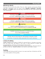 5
5
-
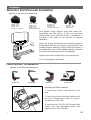 6
6
-
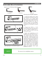 7
7
-
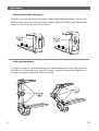 8
8
-
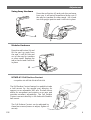 9
9
-
 10
10
-
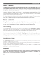 11
11
-
 12
12
-
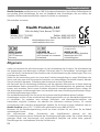 13
13
-
 14
14
-
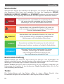 15
15
-
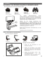 16
16
-
 17
17
-
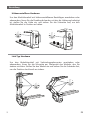 18
18
-
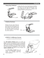 19
19
-
 20
20
-
 21
21
-
 22
22
-
 23
23
-
 24
24
-
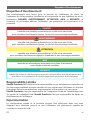 25
25
-
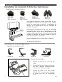 26
26
-
 27
27
-
 28
28
-
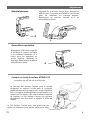 29
29
-
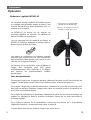 30
30
-
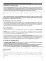 31
31
-
 32
32
-
 33
33
-
 34
34
-
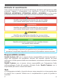 35
35
-
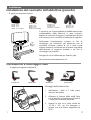 36
36
-
 37
37
-
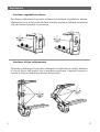 38
38
-
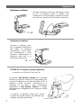 39
39
-
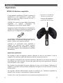 40
40
-
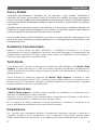 41
41
-
 42
42
-
 43
43
-
 44
44
-
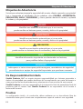 45
45
-
 46
46
-
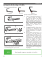 47
47
-
 48
48
-
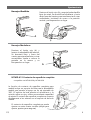 49
49
-
 50
50
-
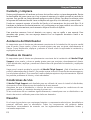 51
51
-
 52
52


Stealth Products P133D13R2 Manual de usuario
- Tipo
- Manual de usuario
en otros idiomas
Artículos relacionados
Otros documentos
-
DRIFT Stealth 2 Manual de usuario
-
Logic3 ps3 freebird stealth wireless gamepad El manual del propietario
-
Leckey N85584 Instrucciones de operación
-
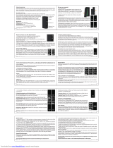 Joyetech e-Vic VTC Mini Manual de usuario
-
VENOM VMX450 El manual del propietario
-
Beyerdynamic beyerdynamic SPACE charcoal Manual de usuario
-
