Sunjoy L-GG030PST-B Hardtop Grill Gazebo Manual de usuario
- Tipo
- Manual de usuario

Questions, problems, missing parts? Before returning to your retailer, call our customer
service department at 1-866-578-6569 anytime 24 hours / 7 days a week, or email to
[email protected] or visit www.sunjoyonline.com.
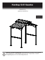
MODEL #L-GG030PST-B
ITEM #0757134
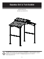
Hardtop Grill Gazebo
Français p. 12
Español p. 24

1
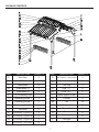
PART
A
B
2
4
4
2
2
1
2
2
4
2
2
2
2
2
DESCRIPTION QUANTITY
C
D1
D2
E
F1
F2
Roof Vent
Base
Base cover
Truss Beam (1)
Connecting Board 3
Truss Beam (2)
Top Connecting Pole
Connecting Board 1
Connecting Board 2
F3
G
H1
H2
H3
I1
Top Hook
Roof Cladding – long panel (1)
Roof Cladding – long panel (2)
Roof Cladding – long panel (3)
Roof Cladding – short panel(1)
I2
Roof Cladding – short panel(3)
Roof Cladding – short panel(2)
I3
PART
2
DESCRIPTION QUANTITY
J
K1
1
2
2
2
4
2
14
24
8
2
6
4
K2
L
M1
M2
M3
M4
N
O
P
Trim Cap
Post1
Post2
Skew Support Piece
Screen
Counter
Tile
Presser 1
Presser 2
Cover Supporting Board
Led light
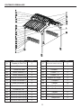
PACKAGE CONTENTS

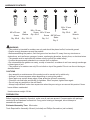
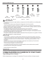
HARDWARE CONTENTS
2
M6 x 15 mm
Screw
Qty. 48+5
M6 x 20 mm
Screw
Qty. 80+8 Qty. 130+13
M6
Washer
M4 x 10 mm
Screw
Qty. 32+4
M6
Wrench
Qty. 2
M6 x 35 mm
Screw
Qty. 2+1
Qty. 8
Φ8*240 mm
Stake
AA BB CC
II
JJ
DD
Z
WARNING
• This product is intended for outdoor use only and should be placed on flat, horizontal ground.
• Ensure enough clearance around the product.
• Before assembling the product, find level ground no less than
6 ft. away from any structures or
obstructions, such as fences, garages, houses, overhanging branches, laundry lines, or electrical wires.
• The gazebo must be anchored with stakes onto the ground for a
dded safety.
• It cannot be permanently attached to a concrete floor or platform.
• Do not assemble the gazebo on sandy, muddy or loose soil, as
stakes do not have enough anchorage
in these types of soil.
• This product is for outdoor use only! Do not climb on top of
the gazebo! Do not use the unit during an
electrical storm!
CAUTIONS
• Any assembly or maintenance of the product must be carried ou
t by adults only.
• Arrange 6 or more manpower when assembling or moving the product.
• Some parts may contain sharp edges. Wear protective gloves if
necessary.
• Check all nuts and bolts periodically for tightness. When req
uired, tighten them again.
• Do not hang any weights on the roof frame.
• Always keep children under close supervision when they are using or are around this product. Never
leave children unattended.
Hook maximum weight: 26 lbs
Estimated Assembly T
ime:
90 minutes
Tools Required for Assembly: Wrench (included) and Phillips Screwdriver (not included).
PREPARATION
Before beginning assembly of product, make sure all parts are present. Compare parts with package
contents list and hardware contents list. If any part is missing or damaged, do not attempt to
assemble the product.

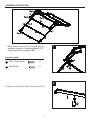
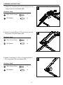
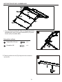
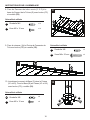
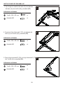
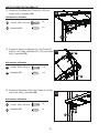
1. Attach truss beam D1 (D2) to top roof vent (A),
assemble them with Connecting Board 2 (F2)
using screw (AA) and washer (BB).
2. Attach top hook (G) to Top Connecting Pole (E).
ASSEMBLY INSTRUCTIONS
3
F
2
F
1
D2
AA
BB
F2
Hardware Used
x 12
M6 x 20 mm Screw
AA
x 12
M6 Washer
BB
E
G
A
D1

ASSEMBLY INSTRUCTIONS
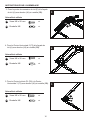
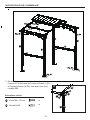
3. Attach Top Connecting Pole (E) to top roof vent (A)
using screw (AA) and washer (BB).
3
G
4. Attach Connecting Board 3 (F3) to top roof vent (A)
using screw (AA) and washer (BB).
4
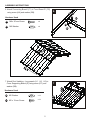
5. Attach Truss Beam D1 (D2) to Connecting Board 3
(F3) using screw (AA) and washer (BB).
5
4
AA
BB
AA
BB
F2
E
A
AA
BB
A
F3D2
D2 D1
AABB
F3
Hardware Used
x 4
M6 x 20 mm Screw
AA
x 4
M6 Washer
BB
Hardware Used
x 8
M6 x 20 mm Screw
AA
x 8
M6 Washer
BB
Hardware Used
x 8
M6 x 20 mm Screw
AA
x 8
M6 Washer
BB

ASSEMBLY INSTRUCTIONS
5
6
K
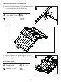
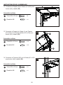
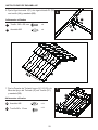
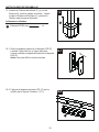
7. Attach Roof cladding – long panels (H1H2H3) to
Cover Supporting Board (O) using screw (CC) and
washer (BB).
7
AA
BB
AA
BB
F1
D2
D1
BB
CC
CC
CC
BB
BB
BB
CC
H1
H2
H3
O
O
Hardware Used
x 8
M6 x 20 mm Screw
AA
x 8
M6 Washer
BB
Hardware Used
x 24
M6 Washer
BB
x 24
M6 x 15 mm Screw
CC
6. Attach Connecting Board 1(F1) to Truss Beam D1 (D2)
using screw (AA) and washer (BB).

ASSEMBLY INSTRUCTIONS
6
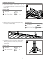
8. Attach the Roof cladding – short panels (I1I2I3)
to Cover Supporting Board (O) using screw (CC) and
washer (BB).
8
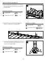
9. Attach trim cap (J) to Top Connecting Pole using
screw (DD) and washer (BB).
9
10. Insert Base cover (C) into Pole (K1 & K2), attach
Base (B) and Pole (K1 & K2) using screw (CC),
washer (BB).
10
Hardware Used
x 16
M6 Washer
BB
x 16
M6 x 15 mm Screw
CC
Hardware Used
x 8
M6 Washer
BB
x 8
M6 x 15 mm Screw
CC
Hardware Used
x 2
M6 Washer
BB
x 2
M6 x 35 mm Screw
DD
BB
CC
I1
K1
K2
I2
I3
CC
BB
BB
BB
BB
CC
CC
BB
DD
J
B
C
DD

7
ASSEMBLY INSTRUCTIONS
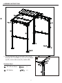
11. Lift the assembled big top and insert the Posts (K1
& K2) into the Truss Beam (1) (D1) and Truss Beam
(2) (D2), secure with screw (AA), washer (BB).
11
Hardware Used
x 8
M6 x 20 mm Screw
AA
x 8
M6 Washer
BB
D1 D2
BB
BB
AA
AA
( )
K1 K2&

8
ASSEMBLY INSTRUCTIONS
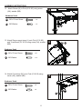
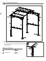
12 . Attach Screen (N) to Pole (K1 & K2) using screw
(AA), washer (BB).
12
13. Attach Skew support piece (L) onto Pole (K1 & K2)
and Truss Beam (D1 & D2) using screw (AA), washer
(BB).
13
14. Attach Countertop (M1) onto Pole (K1 & K2) using
screw (AA), washer (BB).
14
Hardware Used
x 8
M6 x 20 mm Screw
AA
x 8
M6 Washer
BB
Hardware Used
x 16
M6 x 20 mm Screw
AA
x 16
M6 Washer
BB
Hardware Used
x 8
M6 x 20 mm Screw
AA
x 8
M6 Washer
BB
M1
BB
AA
AA
AA
AA
AA
N
BB
BB
BB
BB
K1 K2
&
K1 K2
&
K1 K2&
D1 D2&

9
ASSEMBLY INSTRUCTIONS
15. Lift up Base cover (C), use Stake (II) to fasten the
gazebo on the ground. Put down Base cover (C)
and now your gazebo is ready for use.
15
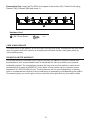
16-1. Take off the back cover of LED light (P), and match
3 pieces AAA batteries into sockets. Attach back
cover to LED light (P).
Note : Batteries are not included.
16-1
16-2. Hang the assembled LED light (P) into holes of
Connecting Board 1 (F1).
16-2
Hardware Used
x 8
Φ8*240 mm Stake
II
II
C
P
P
Q
F1
II

10
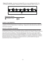
Preassemble Step: Insert the Tile (M2) into the pane of the counter (M1). Fasten the tile using
Presser1 (M3), Presser2 (M4) and screw JJ.
Hardware Used
x 32
M4*10 mm Screw
JJ
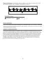
CARE & MAINTENANCE
To extend the life of grill gazebo, do not use when there are high winds. Disassemble and pack away
when the gazebo will not be used for an extended period.Ensure that the metal parts are all dry
before packing away.
SIX-MONTH LIMITED WARRANTY
This limited warranty is extended to the original purchaser and applies to defects in material and
workmanship of your item provided the item is maintained with care and used only for personal,
residential purposes. The manufacturer warrants this item to be free from defects in material and
workmanship for a period of 6 MONTHS. If any defect is found, please call our customer service
department at 1-866-578-6569 for help. The manufacturer will not cover transportation or delivery
costs or compensate the individual or any outside party for assembling or disassembling the product.
This warranty gives you certain rights, and you may have other rights that vary from state to state.
M4
M1
M4
M2
M2
M3
M3
JJ
JJ
JJ
JJ
JJ
JJ

Printed in China
Production number: xxxxxxxx
11
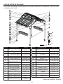
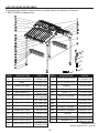
REPLACEMENT PARTS LIST
For replacement parts, call our customer service department at 1-866-578-6569 anytime 24 hours / 7
days a week.
PART
A
B
PART #
P11082A01108
P11616A01108
P11517A01108
P11083A01108
P11084A01108
P12711A01108
P12713A01108
P12712A01108
P12714A01108
P12601A01108
P11928A01108
P11927A01108
P11929A01108
P11930A01108
DESCRIPTION
C
D1
D2
E
F1
F2
Roof Vent
Base
Base cover C
Truss Beam (1)
Connecting Board 3
Truss Beam (2)
Top Connecting Pole
Connecting Board 1
Connecting Board 2
F3
G
H1
H2
H3
I1
Top Hook
Roof Cladding – long panel (1)
Roof Cladding – long panel (2)
Roof Cladding – long panel (3)
Roof Cladding – short panel(1)
I2
Roof Cladding – short panel(3)
Roof Cladding – short panel(2)
I3
PART
P11141A01108
DESCRIPTION
J
K1
P12013A01108
PART #
P11932A01108
P11931A01108
P11140A01108
P11823A01108
P12308A01108
P13601A01108
P10604A01108
P10605A01108
P11015D01108
P10603A01108
P13501A01108
K2
L
M1
M2
M3
M4
N
O
P
Trim Cap
Post1
Post2
Skew Support Piece
Screen
Counter
Tile
Presser 1
Presser 2
Cover Supporting Board
Led light
AA
BB
CC
DD
II
JJ
Z

12
Des questions, des problèmes, des pièces manquantes? Avant de retourner l’article au
détaillant, communiquez avec notre service à la clientèle au 1-866-578-6569 à n’importe
www.sunjoyonline.com.
MODÈLE #L-GG030PST-B
ARTICLE #0757134
Gazebo Gril à Toit Solide

13
PIÈCE
A
B
2
4
4
2
2
1
2
2
4
2
2
2
2
2
DESCRIPTION
C
D1
D2
E
F1
F2
F3
G
H1
H2
H3
I1
Façade du Petit Toit
Base
Couvert de Base
Poutre Inclinée (1)
Poutre Horizontale 3
Poutre Inclinée (2)
Poutre de Connexion du Toit
Poutre Horizontale 1
Poutre Horizontale 2
Crochet du Toit
Panneau de Toiture Long (1)
Panneau de Toiture Long (2)
Panneau de Toiture Long (3)
Panneau de Toiture Court (1)
I2
I3
PIÈCE
2
DESCRIPTION
J
K1
1
2
2
2
4
2
14
24
8
2
6
4
K2
L
M1
M2
M3
M4
N
O
P
Panneau de Toiture Court (3)
Panneau de Toiture Court (2)
Cuirasse
Poteau1
Poteau2
Support de l’Angle
Façade
Comptoir
Carreau
Rondelle Carrée 1
Rondelle Carrée 2
Barre de Support de la toiture
Lampe LED
QTÉ QTÉ
CONTENU DE L’EMBALLAGE

QUINCAILLERIE INCLUSE
14
Visse
M6 x 15 mm
Qté
. 48+5
Visse
M6 x 20 mm
Qté
. 80+8
Qté
. 130+13
Rondelle
M6
Visse
M4 x 10 mm
Qté
. 32+4
Clé M6
Qté
. 2
Visse
M6 x 35 mm
Qté
. 2+1
Qté
. 8
Piquets
Φ8*240 mm
AA BB CC
II
JJ
DD
Z
commencer l’assemblage du produit, assurez-vous d’avoir toutes les pièces. Comparez le conten
PRÉPARATION
A
vant de
u
endommagées, ne tentez pas d’assembler le produit.
AVERTISSEMENTS
• Ce produit est conçu pour emploi extérieur uniquement et doit être installé sur une surface plate
et horizontale.
• Assurez-vous de laisser assez d’espace de dégagement autour de cet article.
• Avant d’assembler le produit, cherchez une surface à niveau a une distance de pas moins de 6
pieds de n’importe quelle structure ou obstructions, comme barrières, garages, maisons, branches
pendantes, fils à tendre ou câbles électriques.
• Le gazebo doit être ancré à la terre avec les piquets pour plus de sécurité.
• Il ne doit pas s’installer de façon permanente a une surface en ciment ou une plateforme.
• N’assemblez pas le gazebo sur de la terre sable, boueuse ou de gravier, car les piquets n’auront
pas assez d’ancrage dans ces sortes de terres.
• Ce produit n’est que pour emploi extérieur uniquement! Ne montez jamais sur le gazebo! N’utilisez
pas cette unité pendant un orage (électrique)!
PRÉCAUTIONS
• Tout montage ou entretien du produit doit être effectué par les personnes adultes uniquement.
• Organisez une équipe d’au moins 6 personnes pour le montage ou le déménagement du produit.
• Certaines pièces peuvent avoir des bords tranchants. Portez des gants de protection s’il est
nécessaire.
• Vérifiez tous les écrous et boulons de temps en temps pour vous assurer qu’ils sont serrés.
Serrez-les encore quand vous le croyez nécessaire.
• N’accrochez pas de poids sur la structure du toit.
•
Les enfants doivent être toujours bien surveillés quand ils sont aux alentours de ce produit.
Ne laissez jamais les enfants sans surveillance.
Limite de poids du crochet: 26 lbs
Temps de Montage Prévu: 90 minutes
Outils nécessaires pour le montage: Clé (comprise) et Tournevis cruciforme (n’est pas compris).

1. Fixez la Poutre Inclinée D1 (D2) à la façade du toit (A),
assemblez-les avec la Poutre Horizontale 2 (F2) avec
boulon (AA) et rondelle (BB).
INSTRUCTIONS POUR L’ASSEMBLAGE
15
Quincaillerie utilisée
x 12
Visse M6 x 20 mm
AA
x 12
Rondelle M6
BB
2. Fixez le crochet du toit (G) à la poutre de connexion
du toit (E).
F
2
F
1
D2
AA
BB
F2
E
G
A
D1

Quincaillerie utilisée
x 4
Visse M6 x 20 mm
AA
x 4
Rondelle M6
BB
Quincaillerie utilisée
x 8
Visse M6 x 20 mm
AA
x 8
Rondelle M6
BB
Quincaillerie utilisée
x 8
Visse M6 x 20 mm
AA
x 8
Rondelle M6
BB
INSTRUCTIONS POUR L’ASSEMBLAGE
3. Fixez la poutre de connexion du toit (E) à la façade
du toit (A) avec boulon (AA) et rondelle (BB).
4. Fixez la Poutre Horizontale 3 (F3) à la façade du
toit (A) avec boulon (AA) et rondelle (BB).
5. Fixez la Poutre Inclinée D1 (D2) à la Poutre
Horizontale 3 (F3) avec boulon (AA) et rondelle (BB).
16
3
G
4
5
BB
AA
AA
BB
F2
E
A
BB
AA
A
F3D2
D2 D1
BB AA
F3

Quincaillerie utilisée
x 8
Visse M6 x 20 mm
AA
x 8
Rondelle M6
BB
INSTRUCTIONS POUR L’ASSEMBLAGE
17
7. Fixez les Panneaux de Toiture longs (H1 H2 H3) à
la Barre de Support de la Toiture (O) avec boulon (CC)
et rondelle (BB).
6. Fixez la poutre horizontale 1(F1) à la poutre inclinée
D1 (D2) avec boulon (AA) et rondelle (BB).
Quincaillerie utilisée
x 24
Rondelle M6
BB
x 24
Visse M6 x 15 mm
CC
6
K
7
AA
BB
AA
BB
F1
D2
D1
BB
CC
CC
CC
BB
BB
BB
CC
H1
H2
H3
O
O

INSTRUCTIONS POUR L’ASSEMBLAGE
18
8. Fixez les Panneaux de toiture courts (I1 I2 I3) à la
barre de Support de la Toiture (O) avec boulon (CC)
et rondelle (BB)
9. Fixez la cuirasse (J) à la Poutre de Connexion du
Toit avec boulon (DD) et rondelle (BB).
Quincaillerie utilisée
x 16
Rondelle M6
BB
x 16
Visse M6 x 15 mm
CC
Quincaillerie utilisée
x 8
Rondelle M6
BB
x 8
Visse M6 x 15 mm
CC
10. Introduisez le couvert de Base (C) dans le Poteau
(K1 et K2), Fixez la Base (B) au Poteau (K1 et K2)
avec boulon (CC), rondelle (BB).
Quincaillerie utilisée
x 2
Rondelle M6
BB
x 2
Visse
M6 x 35 mm
DD
8
9
10
BB
CC
I1
K1
I2
I3
CC
BB
BB
BB
BB
CC
CC
BB
DD
J
B
C
DD
K2

19
INSTRUCTIONS POUR L’ASSEMBLAGE
11. Soulevez le grand toit assemble et introduisez les
Poteaux (K1 et K2) dans les Poutres Inclinées (1) (D1)
et Poutres Inclinées (2) (D2), fixez avec Visse (AA),
rondelle (BB).
Quincaillerie utilisée
x 8
Visse M6 x 20 mm
AA
x 8
Rondelle M6
BB
11
D1
(
D2
BB
BB
AA
AA
)
K2K1 &

20
INSTRUCTIONS POUR L’ASSEMBLAGE
12. Connectez la Façade (N) au Poteau (K1 et K2) avec
boulon (AA), rondelle (BB).
13. Connectez le Support de l’Angle (L) aux Poteaux
(K1 et K2) et aux Poutre Inclinées (D1 et D2) avec
boulon (AA), rondelle (BB).
14. Connectez le Comptoir (M1) sur le Poteau (K1 et K2)
avec boulon (AA), rondelle (BB).
Quincaillerie utilisée
x 8
Visse M6 x 20 mm
AA
x 8
Rondelle M6
BB
Quincaillerie utilisée
x 8
Visse M6 x 20 mm
AA
x 8
Rondelle M6
BB
Quincaillerie utilisée
x 16
Visse M6 x 20 mm
AA
x 16
Rondelle M6
BB
12
13
14
M1
BB
AA
AA
AA
AA
AA
N
BB
BB
BB
BB
K1
&
K2
K1
&
K2
K1 & K2
D1 & D2

21
INSTRUCTIONS POUR L’ASSEMBLAGE
15. Soulevez le Couvert de la Base (C), avec les
Piquets (II), ancrez le gazebo à la terre. Rabaissez
le Couvert de la Base (C) et maintenant votre
gazebo est prêt à en profiter.
15
16-1. Enlevez le couvert arrière de la Lampe LED (P),
et introduisez 3 piles AAA dans leur espace
correspondent. Revissez le Couvert Arrière de
la lampe LED (P).
Avis : Les piles ne sont pas comprises.
16-1
16-2. Accrochez la Lampe LED (P) assemblée dans
les orifices de la Poutre de Connexion 1 (F1).
16-2
Quincaillerie utilisée
x 8
Piquets Φ8*240 mm
II
II
C
P
P
Q
F1
II

22
Étape de Pré Montage : Introduisez les carreaux (M2) dans les cadres du comptoir (M1). Fixez
les Rondelles Carrées 1 (M3), Rondelles Carrées2 (M4) et visses JJ.
Quincaillerie utilisée
x 32
Visse M4 x 10 mm
JJ
SOIN ET ENTRETIEN
Pour que votre gazebo gril dure plus longtemps, ne l’utilisez pas quand il y a du vent fort. Démontez-le
et gardez le pendant des périodes longues de ne pas l’employer. Assurez-vous que les que les métal
soient sèches avant de les garder.
GARANTIE LIMITÉE DE SIX MOIS
Cette garantie limitée est offerte à l’acheteur originel et s’applique aux défauts matériels et de main
d’œuvre de l’article à condition que l’article soit entretenu avec soin et utilisé uniquement pour emploi
personnel, résidentiel. Le fabricant garanti cet article de n’avoir aucun défaut matériaux ou de main
d’œuvre pendant une période de 6 MOIS. S’il se trouve un défaut, appelez s’il vous plait le Secteur
du Service à la Clientèle au 866-578-6569 pour de l’aide. Le fabricant ne couvre pas les frais de
transport ou de livraison et ne compense pas l’individu ou n’importe que autre personne pour le
montage et démontage du produit. Cette garantie vous donne certains droits, et vous pourriez
aussi avoir d’autres droits qui varient d’un état à un autre.
M4
M1
M4
M2
M2
M3
M3
JJ
JJ
JJ
JJ
JJ
JJ

Façade du Petit Toit
Base
Couvert de Base
Poutre Inclinée (1)
Poutre Horizontale 3
Poutre Inclinée (2)
Poutre de Connexion du Toit
Poutre Horizontale 1
Poutre Horizontale 2
Crochet du Toit
Panneau de Toiture Long (1)
Panneau de Toiture Long (2)
Panneau de Toiture Long (3)
Panneau de Toiture Court (1)
Panneau de Toiture Court (3)
Panneau de Toiture Court (2)
Cuirasse
Poteau1
Poteau2
Support de l’Angle
Façade
Comptoir
Carreau
Rondelle Carrée 1
Rondelle Carrée 2
Barre de Support de la toiture
Lampe LED
Imprimé en Chine
Numéro de production: xxxxxxxx
23
LISTE DE PIÈCES DE RECHANGE
Pour pièces de rechange, veuillez appeler notre secteur de Service à la clientèle au 1-866-578-6569
à n’importe quelle heure.
PIÈCE
A
B
DESCRIPTION
C
D1
D2
E
F1
F2
F3
G
H1
H2
H3
I1
I2
I3
PIÈCE
DESCRIPTION
J
K1
K2
L
M1
M2
M3
M4
N
O
P
AA
BB
CC
DD
II
JJ
Z
PART #
P11082A01108
P11616A01108
P11517A01108
P11083A01108
P11084A01108
P12711A01108
P12713A01108
P12712A01108
P12714A01108
P12601A01108
P1928A01108
P11927A01108
P11929A01108
P11930A01108
P11141A01108
P12013A01108
PART #
P11932A01108
P11931A01108
P11140A01108
P11823A01108
P12308A01108
P13601A01108
P10604A01108
P10605A01108
P11083A01108
P10603A01108
P13501A01108

24
MODELO #L-GG030PST-B
ARTÍCULO #0757134
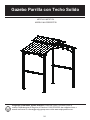
Gazebo Parrilla con Techo Solido
Preguntas, problemas, piezas faltantes? Antes de volver a la tienda, llame a
nuestro Departamento de Servicio al Cliente al 1-866-578-6569, da cualquier hora, o
mande un correo E a [email protected] visite www.sunjoyonline.com.

25
PIEZE
A
B
2
4
4
2
2
1
2
2
4
2
2
2
2
2
DESCRIPCIÓN
C
D1
D2
E
F1
F2
F3
G
H1
H2
H3
I1
Fachada del Techo Pequeño
Base
Cubierta de Base
Viga Inclinada (1)
Viga Horizontal 3
Viga Inclinada (2)
Viga de Conexión del Techo
Viga Horizontal 1
Viga Horizontal 2
Gancho del Techo
Panel de Techado Largo (1)
Panel de Techado Largo (2)
Panel de Techado Largo (3)
Panel de Techado Corto (1)
I2
I3
PIEZE
2
DESCRIPCIÓN
J
K1
1
2
2
2
4
2
14
24
8
2
6
4
K2
L
M1
M2
M3
M4
N
O
P
Panel de Techado Corto (3)
Panel de Techado Corto (2)
Moldura
Poste1
Poste2
Apoyo de Esquina
Fachada
Mostrador
Azulejo
Arandela Cuadrada 1
Arandela Cuadrada 2
Barre de Support de la toiture
Lámpara LED
CANTIDAD CANTIDAD
CONTENIDO DEL PAQUETE

AVISOS
• Este producto esta concebido par empleo al exterior únicamente y se debe instalar en una
superficie plana y horizontal.
• Asegúrese de dejar bastante espacio de distancia alrededor de este articulo.
• Antes de montar este producto, busque una superficie nivelada y a una distancia de no menos
de 6 pies de cualquier estructura u obstrucción, como verjas, garajes, casas, ramas colgantes,
cuerdas para tender o cables eléctricos.
• El gazebo se debe anclar a la tierra con las estacas para mas seguridad.
• No se debe instalar permanentemente en una superficie de cemento o una plataforma.
• No monte el gazebo sobre tierra arenosa, lodosa o de grava, porque las estacas no podrán
anclarse bastante en esas clases de tierras.
• Este producto es únicamente para empleo al exterior! No monte nunca sobre el Gazebo! No
utilice esta unidad cuando hay peligro de tormenta eléctrica!
PRECAUCIONES
• Todo montaje y mantenimiento del producto deberá ser realizado por personas adultas únicamente.
• Organice un equipo de por lo menos 6 personas para el montaje o el traslado de este producto.
• Algunas piezas pueden tener bordes afilados. Póngase guantes de protección si es necesario.
• Verifique todas las tuercas y tornillos de vez en cuando para asegurarse que están apretados.
Apriételos otra vez si lo encuentra necesario.
• No cuelgue ningún peso sobre la estructura del techo.
• Los niños deben estar siempre bajo vigilancia cuando se encuentran en los alrededores de este
productor. No deje nunca a los niños sin vigilancia.
Limite de peso del gancho: 26 lbs
Herramienta necesaria para el montaje: Llave (incluida) y desto
rnillador en cruz (no está incluido).
Tiempo previsto de montaje: 90 minutos
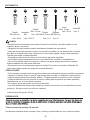
ADITAMENTOS
26
Tornillo
M6 x 15 mm
Cant
. 48+5
Tornillo
M6 x 20 mm
Cant. 80+8 Cant. 130+13
Arandela
M6
Llave
M4 x 10 mm
Cant.
32+4
Llave M6
Cant.
2
Tornillo
M6 x 35 mm
Cant. 2+1
Cant. 8
Estacas
Φ8*240 mm
AA BB CC
II
JJ
DD
Z
PREPARACIÓN

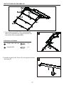
1. Fije la Viga Inclinada D1 (D2) a la fachada del
techo (A), conéctelas a la Viga Horizontal 2 (F2)
con tornillo (AA) y arandela (BB).
INSTRUCCIONES DE ENSAMBLAJE
27
Aditamentos utilizados
x 12
Tornillo
M6 x 20 mm
AA
x 12
Arandela
M6
BB
2. Atornille el gancho del Techo (G) a la viga de conexión
del techo (E).
F
2
F
1
D2
AA
BB
F2
E
G
A
D1

INSTRUCCIONES DE ENSAMBLAJE
3. Fije la viga de conexión del techo (E) a la fachada
del techo (A) con tornillo (AA) y arandela (BB).
4. Conecte la Viga Horizontal 3 (F3) a la fachada del
techo (A) con tornillo (AA) y arandela (BB).
5. Fije la Viga Inclinada D1 (D2) a la Viga Horizontal 3 (F3)
con Tornillo (AA) y arandela (BB).
28
Aditamentos utilizados
x 4
Tornillo
M6 x 20 mm
AA
x 4
Arandela
M6
BB
Aditamentos utilizados
x 8
Tornillo
M6 x 20 mm
AA
x 8
Arandela
M6
BB
Aditamentos utilizados
x 8
Tornillo
M6 x 20 mm
AA
x 8
Arandela
M6
BB
3
G
4
5
BB
AA
AA
BB
F2
E
A
BB
AA
A
F3D2
D2 D1
BB AA
F3

INSTRUCCIONES DE ENSAMBLAJE
29
7. Fije los Paneles de Techado largos (H1 H2 H3) a la
Barra de Apoyo del Techado (O) con Tornillo (CC)
y arandela (BB).
6. Fije la Viga Horizontal 1(F1) a la viga inclinada D1 (D2)
con tornillo (AA) y arandela (BB).
Aditamentos utilizados
x 24
Arandela
M6
BB
x 24
Tornillo M6 x 15 mm
CC
Aditamentos utilizados
x 8
Tornillo
M6 x 20 mm
AA
x 8
Arandela
M6
BB
6
K
7
AA
BB
AA
BB
F1
D2
D1
BB
CC
CC
CC
BB
BB
BB
CC
H1
H2
H3
O
O

Aditamentos utilizados
x 16
Arandela
M6
BB
x 16
Tornillo M6 x 15 mm
CC
Aditamentos utilizados
x 8
Arandela
M6
BB
x 8
Tornillo M6 x 15 mm
CC
INSTRUCCIONES DE ENSAMBLAJE
30
8. Fije los Paneles de Techado cortos (I1 I2 I3) a la
Barra de Apoyo del Techado (O) con tornillo (CC)
y arandela (BB).
9. Fije la moldura (J) a la Viga de Conexión del
Techo con tornillo (DD) y arandela (BB).
10. Introduzca la cubierta de la Base (C) en el Poste
(K1 y K2), Fije la Base (B) al Poste (K1 y K2) con
tornillo (CC), arandela (BB).
Aditamentos utilizados
x 2
Arandela
M6
BB
x 2
Tornillo
M6 x 35 mm
DD
8
9
10
BB
CC
I1
K1
I2
I3
CC
BB
BB
BB
BB
CC
CC
BB
DD
J
B
C
DD
K2

31
INSTRUCCIONES DE ENSAMBLAJE
11. Levante el montaje del techo grande e introduzca
los Postes (K1 et K2) en las Vigas Inclinadas (1) (D1)
y las Vigas Inclinadas (2) (D2), fije con un Tornillo (AA),
y arandela (BB).
Aditamentos utilizados
x 8
Tornillo
M6 x 20 mm
AA
x 8
Arandela
M6
BB
11
D1
(
D2
BB
BB
AA
AA
)
K2K1 &

32
INSTRUCCIONES DE ENSAMBLAJE
12. Conecte la Fachada (N) al Poste (K1 y K2) con
tornillo (AA), y arandela (BB).
13. Conecte el Apoyo de Esquina (L) a los Postes (K1
et K2) y a las Vigas Inclinadas (D1 y D2) con tornillo
(AA), y arandela (BB).
14. Conecte el Mostrador (M1) a los Postes (K1 et K2)
con tornillo (AA), y arandela (BB).
Aditamentos utilizados
x 8
Tornillo
M6 x 20 mm
AA
x 8
Arandela
M6
BB
Aditamentos utilizados
x 8
Tornillo
M6 x 20 mm
AA
x 8
Arandela
M6
BB
Aditamentos utilizados
x 16
Tornillo
M6 x 20 mm
AA
x 16
Arandela
M6
BB
12
13
14
M1
BB
AA
AA
AA
AA
AA
N
BB
BB
BB
BB
K1
&
K2
K1
&
K2
K1 & K2
D1 & D2

33
INSTRUCCIONES DE ENSAMBLAJE
15. Levante la Cubierta de la Base (C), y con las
Estacas (II), ancle el gazebo a la tierra. Vuelva
a bajar la Cubierta de la Base (C) y ahora Su
Gazebo está listo para disfrutarlo.
15
16-1. Quite la tapadera trasera de la lámpara LED (P),
e instale 3 pilas AAA en su lugar adecuado.
Vuelva a instalar la tapadera trasera de la lámpara
LED (P).
Aviso: Las pilas AAA no están incluidas.
16-1
16-2. Cuelgue la lámpara montada LED (P) en los
orificios de la Viga de Conexión 1 (F1).
16-2
Aditamentos utilizados
x 8
Estacas Φ8*240 mm
II
II
C
P
P
Q
F1
II

34
Etapa de Pre montaje : Introduzca los Azulejos (M2) en los marcos del Mostrador (M1). Fije
los Azulejos con las Arandelas Cuadradas1 (M3), Arandelas cuadradas 2 (M4) y Tornillos JJ.
Aditamentos utilizados
x 32
Llave M4 x 10 mm
JJ
CUIDADO Y MANTENIMIENTO
Para que vuestro gazebo parrilla dure más tiempo, no lo utilice cuando hay vientos fuertes. Desmóntelo
y guárdelo si no lo va a utilizar durante un tiempo largo. Asegúrese que las piezas de metal estén muy
secos antes de guardarlo.
GARANTIA LIMITADA DE SEIS MESES
Esta garantía limitada se le ofrece al comprador original y se aplica a defectos materiales y de mano
de obra del articulo siempre y cuando el articulo haya sido mantenido con cuidado y utilizado únicamente
para empleo personal, residencial. El fabricante garantiza que este articulo no tiene ningún defecto
material o de mano de obra durante un periodo de 5\6 MESES. Si encuentra algún defecto, llame por
favor a la Sección de Servicio al Cliente al 866-578-6569 para que le ayuden. El fabricante no cubre los
gastos de transporte o de entrega y no compensa al individuo o a ninguna otra persona por el montaje y
desmontaje del producto. Esta garantía le da algunos derechos, y podría también tener algunos
derechos más que varían de un estado al otro.
M4
M1
M4
M2
M2
M3
M3
JJ
JJ
JJ
JJ
JJ
JJ

Fachada del Techo Pequeño
Base
Cubierta de Base
Viga Inclinada (1)
Viga Horizontal 3
Viga Inclinada (2)
Viga de Conexión del Techo
Viga Horizontal 1
Viga Horizontal 2
Gancho del Techo
Panel de Techado Largo (1)
Panel de Techado Largo (2)
Panel de Techado Largo (3)
Panel de Techado Corto (1)
Panel de Techado Corto (3)
Panel de Techado Corto (2)
Moldura
Poste1
Poste2
Apoyo de Esquina
Fachada
Mostrador
Azulejo
Arandela Cuadrada 1
Arandela Cuadrada 2
Barre de Support de la toiture
Lámpara LED
Impreso en China
Numero de producción: xxxxxxxx
35
LISTA DE PIEZAS DE RECAMBIO
Para piezas de recambio, llame por favor a nuestra sección de Servicio al Cliente al
1-866-578-6569 a cualquier hora.
PIEZE
A
B
DESCRIPCIÓN
C
D1
D2
E
F1
F2
F3
G
H1
H2
H3
I1
I2
I3
PIÈCE
DESCRIPTION
J
K1
K2
L
M1
M2
M3
M4
N
O
P
AA
BB
CC
DD
II
JJ
Z
PART #
P11082A01108
P11616A01108
P11517A01108
P11083A01108
P11084A01108
P12711A01108
P12713A01108
P12712A01108
P12714A01108
P12601A01108
P11928A01108
P11927A01108
P11929A01108
P11930A01108
P11141A01108
P12013A01108
PART #
P11932A01108
P11931A01108
P11140A01108
P11823A01108
P12308A01108
P13601A01108
P10604A01108
P10605A01108
P11015D01108
P10603A01108
P13501A01108
-
 1
1
-
 2
2
-
 3
3
-
 4
4
-
 5
5
-
 6
6
-
 7
7
-
 8
8
-
 9
9
-
 10
10
-
 11
11
-
 12
12
-
 13
13
-
 14
14
-
 15
15
-
 16
16
-
 17
17
-
 18
18
-
 19
19
-
 20
20
-
 21
21
-
 22
22
-
 23
23
-
 24
24
-
 25
25
-
 26
26
-
 27
27
-
 28
28
-
 29
29
-
 30
30
-
 31
31
-
 32
32
-
 33
33
-
 34
34
-
 35
35
-
 36
36


Sunjoy L-GG030PST-B Hardtop Grill Gazebo Manual de usuario
- Tipo
- Manual de usuario
en otros idiomas
Otros documentos
-
Allen + Roth GF-18S112B Guía de instalación
-
Arrow IWC108 Manual de usuario
-
-
-
-
Apex Digital GF-19S067B Manual de usuario
-
Swing-N-Slide Playsets WS 8344 Instrucciones de operación
-
-
 ShelterLogic PS53 Manual de usuario
-
