Unique Home Designs 5V0002DL0AL00B Guía de instalación
- Tipo
- Guía de instalación

MK1345 07192017
Advanced Screen Systems
Advanced Screen Systems
Advanced
Screen Systems
Advanced
Screen Systems
Advanced
Screen Systems
Advanced
Screen Systems
Premium Security Screen Door
Installation Instructions
Surface Mount
Advanced Screen Systems
Advanced Screen Systems
Advanced Screen Systems
Advanced Screen Systems
Advanced Screen Systems
Advanced Screen Systems
Meshtec Co. logo from them Recreated for UHD use
Advanced Screen Systems
Advanced Screen Systems
Advanced Screen Systems
Advanced Screen Systems
Advanced Screen Systems
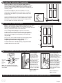
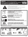
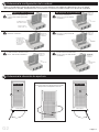
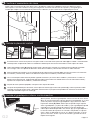
• Read completely through the installation instructions before proceeding with installation
• Installation requires two people
• Use appropriate protective equipment, including safety glasses
• Children should not be allowed in work area
• Failure to install door correctly could result in injury
Above average degree of difculty. Requires
installation experience.
INSTALLATION
EASY HARD
INSTALLATION
EASY HARD
PROFESSIONAL INSTALLATION RECOMMENDED
Even professional installers will benet from watching.
REVIEW INSTALLATION VIDEO
Customer service and technical support are available.
Monday - Friday: 6:30am - 4pm PST
CONTACT US BEFORE RETURNING
1-866-317-8867
NEED HELP?
RETAIN PACKAGING DURING INSTALLATION
Do NOT discard packaging materials until
installation is complete
Page 1
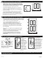
RECOMMENDED TOOLS
Safety Glasses Measuring Tape
Pencil
Level
Drill Bit
1/8"
minimum length: 2-3/4"
Phillips-head & Flat-blade
screwdriver
123456
234
1
2
3
4
5
6
7
8
10
12
15
18
24
30
5
15
25
35
45
55
65
75
85
123456
234
1
2
3
4
5
6
7
8
10
12
15
18
24
30
5
15
25
35
45
55
65
75
85
Square
Needle Nose
Pliers
Box Cutter
Rubber Mallet
Wood Blocks (2"x4"x6")
Shims
Paintable Caulk &
Caulk Gun
Tin Snips
Drill
G2

B
B1
D
C
F
I
A
A1
O
P
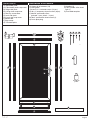
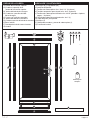
A) Top header jamb
A1) Top header jamb snap cover
B) Hinge-side jamb
B1) Hinge-side snap cover
C) Security screen door
D) Lock-side jamb
D1) Lock-side snap cover
E) Bottom bar
F) Bug sweep
G) Threshold plate
DOOR PARTS HARDWARE & FASTENERS
H) Hinges (3) & fasteners (18)
I) Latch guard
J) #10x2-1/2" at-head screws (12 pcs.)
K) #6 x 2" temporary drywall screws (6 pcs)
L) #6x5/8" pan head screws
(painted - 3 pcs, black - 10 pcs)
M) #8x1" painted at-head screws (2)
N) Latch plate plug
O) Handles (2)
P) Lock cylinder & at-head
bolt (1)
Q) Threshold template
D1
E
G
Q
M
H
J K L
2” drywall 1” athead 5/8” panhead 3/4” panhead 1” panhead2-1/2” athead 1/2” athead 1-1/2” panhead
bumper
cap
3-1/2” athead 1/2” panhead bolt
plug
2” drywall 1” athead 5/8” panhead 3/4” panhead 1” panhead2-1/2” athead 1/2” athead 1-1/2” panhead
bumper
cap
3-1/2” athead 1/2” panhead bolt
plug
2” drywall 1” athead 5/8” panhead 3/4” panhead 1” panhead2-1/2” athead 1/2” athead 1-1/2” panhead
bumper
cap
3-1/2” athead 1/2” panhead bolt
plug
N
Active door - Double Cylinder
Inactive door - Double Cylinder
P
Page 2
G2
2” drywall 1” athead 5/8” panhead 3/4” panhead 1” panhead2-1/2” athead 1/2” athead 1-1/2” panhead
bumper
cap
3-1/2” athead 1/2” panhead bolt
plug
Touch-up
paint

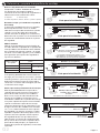
Additional sloped trim may be added in the reverse
direction to create at surface
OR
Sloped trim may be removed or replaced with at
trim to properly mount your new security door
StudStud
Entry Door
Sloped Trim (Top View)
Entry Door Jamb
Sloped Trim
1" minimum
mounting
surface
1" minimum
mounting
surface
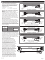
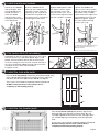
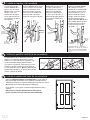
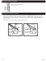
Determine Type and Readiness of Mounting
Surface
Your security door will require a minimum
mounting surface of 1" on the trim above, and
on both sides of your entry door. Mounting
screws must be secured to a stud in the wall.
Review diagrams at right and determine which
one most resembles the trim around the entry
door to which you will mount your security door.
Inspect Your Entryway for Obstructions
Check for any obstructions above and around
your entryway that may prevent the outward
swing of your new security door, and/or its
installation, such as:
Light xtures
Door bell
Low overhang
Trees, bushes, or hanging plants
Security Door
Size
Fits Door Opening Sizes
Width (W) Height (H)
32" x 80" 31 7/8" - 32 3/8"
79 3/4" - 81 3/4"
36" x 80" 35 7/8" - 36 3/8"
36" x 96" 35 7/8" - 36 3/8" 95 3/4" - 97 3/4"
Measure Your Opening
Measure between the inside edges of the left
and right mounting surfaces for opening width.
Measure between the bottom edge of the upper
mounting surface and the existing threshold
for opening height. Use the following chart and
these measurements to be sure the security door
will t your opening.
If the opening identied does not fall within the
t range, you can check to see if there is another
mounting surface in your entryway that will work,
build your mounting surface out using stop or
similar trim, or remove and recongure your trim
to fall within the t range.
Ready for installation
Brick Moulding (Top View)
Brick
moulding trim
StudStud
Entry Door Jamb
Entry Door
1" minimum
mounting
surface
1" minimum
mounting
surface
Ready for installation
Flat Trim (Top View)
Entry Door
StudStud
Entry Door Jamb
1" minimum
mounting
surface
1" minimum
mounting
surface
Flat Trim
Minimum 2-3/8"
Minimum 2-3/8"
Ready for installation
Stucco 1 (Top View)
Entry Door
StudStud
Entry Door Jamb
1" minimum
mounting
surface
1" minimum
mounting
surface
Stucco
Pop-out
Minimum 2-3/8"
CAUTION: Check closely for possible hardware interference!
mounted between stucco pop-outs
Stucco 2 (Top View)
Entry Door
StudStud
Entry Door Jamb
1" minimum
mounting
surface
Stucco
Pop-out
Minimum 2-3/8"
mounted to front surface
of stucco pop-outs
1" minimum
mounting
surface
This application will require 6" screws (sold separately)
Hinge-side
jamb
Entry Door
Premium Security Door w/ Meshtec Screen
Lock-side
jamb
Check for Hardware Interference
Measure the depth from the corner of
your mounting surface to your existing
entry door hardware. If this measurement
is 2-3/8" or greater there is no potential
for hardware interference. If the
measurement is less than 2-3/8", measure
from the edge of the mounting surface
on top of the door to the top and bottom
edge of the part of your existing hardware
that intrudes into the 2-3/8" clearance.
If either of these two measurements falls
between 39-1/4" and 43-1/4", the security
door and existing door hardware will
interfere with each other. You can either
build your mounting surface out to create
the clearance required or mount your
security door with an opposite swing to
your main entry door. If there is less than
2-3/8" clearance between the surface of
the main entry door and the security door
mounting surface, a build out is required.
Determining Your Build Out Area (continued)Identify and prepare mounting surface
1
Page 3
Minimum 2-3/8"
G2
Minimum 2-3/8"

TOP
BB
C
TOP
C
B
Top View
B
C
Top View
B
C
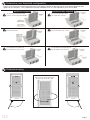
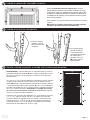
Screen Door Rotation
With top of door always remaining at
the top, rotate door to left or right
Look at your existing entry door threshold and use the diagrams below to determine which threshold conguration best
applies to your entryway. This will determine whether a bottom bar is or is not required for your security door.
The existing threshold sticks out
beyond the trim by 3/16" or less.
The concrete and threshold sets
back behind the trim.
The concrete is set back and lacks
space to mount to the threshold plate.
The existing threshold extends past
the trim between 3/16" and 7/8".
Bottom Bar NOT RequiredBottom Bar Required
The concrete extends at least
7/8" further than your trim.
The existing threshold extends
beyond the trim by 7/8" or more.
Determining Your Build Out Area (continued)Determine your threshold conguration
2
Determining Your Build Out Area (continued)Determine swing
3
Page 4
G2

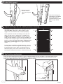
Note: As stated in Step 4, there should be a minimum of 2-3/4" space
below the lock side jamb and below the entire width of the door to
allow space for the bottom bar. If a 2-3/4" space exists across the entire
doorway, you do NOT need to install a bottom bar.
The bottom bar (E) will need to be installed 1/8" to 1/4"
lower than the existing doorway so that there is a slope to
the threshold. This allows any moisture to drain away from
the entry door.
Center the bottom bar in the door opening. Be sure the bracket
opening is towards the house. Install the bottom bar using two
black #6x5/8" pan head screws (L) as shown. Keep your drill
on a low speed so the threads do not strip.
E
HOUSE
If there is NOT a 2-3/4" space below both jambs it is
necessary to install the bottom bar assembly.
It is okay to
move the jambs up within the doorway to ensure this space, as
long as the top of the jambs do not go beyond the top-edge of your
mounting surface.
Place the hinge-side jamb (B) into position over bottom
bar (E), verify that it is plumb and level against the mounting
surface, and install two #6x2" dry wall screws (K) supplied into
holes 1 & 5 (see diagram), and temporarily mount the hinge-
side jamb (B).
2
1
5
4
3
E
B
These screws are inserted to temporarily hold the jamb plumb.
Do NOT install permanent screws until the door is
completely installed and working properly.
Place hinge (H)
over pre-drilled
holes on the door.
The at part of the
hinge attaches to
the door. The barrel
side of the hinge
should always be on
the outside of the
door. Use screws
provided with the
hinges and attach all
3 hinges to the door.
Note: Do NOT over
tighten screws.
Jamb Side:
Anti-bow
point
Door Side:
Anti-bow
point
receiving
hole
Note: The Anti-bow point receiving
hole lines up with the pre-drilled hole
on the door.
Determining Your Build Out Area (continued)Install the bottom bar if applicable
4
Determining Your Build Out Area (continued)Install the hinge-side jamb
5
Determining Your Build Out Area (continued)Attach hinges to door and door jamb
6
Have a helper hold
the door in place. It is
important the door is held
in proper alignment so
the rst mounting screw
in each hinge is driven
straight into the door
panel. It may help to use
blocks or similar props
to assist in keeping the
door properly aligned.
Attach all 3 hinges to
door using the screws
provided.
Note: Do NOT over
tighten screws.
CAUTION: Do NOT lay door on it's side so that it rests on the 3-point lock throws.
Page 5
G2
To avoid interferrence with the primary entry door handle
do NOT shift too far to one side.

1) Start on the interior
side of the door. With
the handle (O) facing
toward the screen,
insert the spindle
and mounting screws
through the mortise gear
in the door panel.
Determining Your Build Out Area (continued)
1
Install handle and lockset
7
2) On the exterior of the
door with the handle pointing
toward the screen, align the
openings on the inside of the
handle with the spindle and
mounting screws. Position the
handle against door frame.
3) While holding both handle
trim plates in place, tighten
the mounting screws and
then back off 2 turns. These
screws will be tightened after
the lock cylinder is installed.
Spindle
4) From the inside of the
door, insert the lock cylinder
(P) into the door through the
trim plate. Using a Phillips-
head screw driver, tighten the
at-head bolt until snug. Do
NOT over-tighten. Tighten
the two handle mounting
screws until snug.
Lock cylinder
Spindle
Trim plate
screw
Trim plate
screw
7
6
10
9
8
H
B D
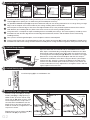
Place the lock-side jamb (D) into position over bottom bar (E), verify
that it is plumb and level against the mounting surface, and install
two #6x2" drywall screws (K) into holes 6 & 10 (see diagram).
These screws are inserted to temporarily hold the jamb plumb.
Do NOT install permanent screws until the door is
completely up and working properly.
Determining Your Build Out Area (continued)
1
Install the lock-side jamb
9
Page 6
G2
A
C
B D
Place the top header jamb (A) into position, align ush on
both ends with each side jamb. Install one #6x2" dry wall
screw (K) supplied into the hole on the lock side (right side in
this example diagram) to temporarily mount the top header
jamb.
These screws are inserted to temporarily hold the jamb plumb.
Do NOT install permanent screws until the door is
completely installed and working properly.
Determining Your Build Out Area (continued)
1
Install the top header jamb
10
Determining Your Build Out Area (continued)
1
Flip center latch (if necessary)
8
Depending on right or left side placement of active door
the center latch may need to be ipped. With a small
phillips-head screwdriver loosen (do not remove) the
screw just enough to raise the latch and turn clockwise
to reverse the position. Note: the high side of the latch
should be on the exterior side of the door.
Re-tighten screw.
Door
exterior
Door
exterior
High side
For duplication and rekeying purposes,
the lock cylinder provided uses a
Kwikset
®
keyway.
“Kwikset” is a registered trademark of Newfry LLC.
Flat-head
bolt

Page 7
CAUTION: The door must be close enough to the lock-
side jamb (D) to engage the 3-point locking system
trigger. If not, the hardware will not operate properly.
Once in position the door should align at the top and
down the side evenly. If adjustment is needed loosen
(do NOT remove) the top temporary screw in the side
jambs and the temporary screw in the top jamb (A). Use
a rubber mallet to tap the right or left side jamb so door
becomes aligned. Test door for proper engagement of
the locking system trigger then re-tighten temporary
screws.
Pre-drill with 1/8" drill bit in remaining holes 2,3,4,7,8 &
9 of side jambs and remaining hole of the top jamb then
install permanent screws
#10x2-1/2" at-head screws
(
J).
Remove temporary screws one at a time from holes 1,5,6,10 &
top and replace with permanent #10x2-1/2" at-head screws
(
J).
2
1
5
4
3
7
6
10
9
8
DB
A
Determining Your Build Out Area (continued)
1
Install latch guard
11
Determining Your Build Out Area (continued)
1
Test locking mechanism
13
G2
1. Remove top and
bottom screws
from the one-piece
gear.
Verify that the locking mechanism opens, closes and locks properly. To test, pull down on the door handle to open
the door. Pull up on the door handle to engage the 3-point locking mechanism then turn the thumb-turn on the
inside of the door clockwise or turn the key counterclockwise to lock.
Determining Your Build Out Area (continued)
1
Adjust and align door & install permanent screws
12
2. Attach the latch guard
provided in the hardware
box using two #8x1"
painted at-head screws
(M) in the pre-drilled
holes.

Existing door contour Make cardboard template
Fit template to contour Cut template to contour
Mark threshold plate
Cut threshold plate to t
1
2
3 4 5
6
The contour of door framing varies, making it necessary to cut the threshold plate (G) to t. We recommend cutting a cardboard
template (Q) to t the opening rst, to avoid cutting the threshold plate incorrectly.
4
5
6
1
2
3
Page 8
Determining Your Build Out Area (continued)
1
Install threshold plate
14
G2
Determining Your Build Out Area (continued)
1
Install bug sweep
15
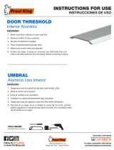
Open the door. With the notched side on the interior of the screen
door slip the multi-blade bug sweep (F) onto the bottom of the door.
Hold sweep in place and close the door. Allow the sweep to fall and
sit resting on the threshold plate (G). Note: Be sure there is not a gap
between the sweep and the threshold plate and that the sweep is
centered on the bottom of the door. Using two #6x5/8" painted pan
head screws (L), attach the sweep to the bottom of the door on the
interior. Test that the door opens and closes freely. If not, loosen the
screws and make necessary adjustments. Re-tighten screws and test
again. Repeat until successful.
Determining Your Build Out Area (continued)
1
Install latch plug
16
Install latch plug (N) in unused bottom slot.
Determining Your Build Out Area (continued)
1
Install the snap covers
17
Place the snap cover (A1) in the top-
header jamb (Fig. 1, step 1).Using a
rubber mallet, hit on the side of snap
cover seen in (Fig. 2) to securely snap
cover into place. Once snap cover is
secured, hold a wood block over the
length of the snap cover and hit with
mallet to smooth any irregularities in the
snap cover surface.
Repeat process for the hinge-side (B1)
and lock-side (D1) snap covers.
Snap cover
Door jamb
1
2
Fully seated
Fig. 1 Fig. 2
Lay provided cardboard template (Q) on top of the bottom bar and push into existing threshold as far as it will go. Using a straight
edge, mark the template at the various widths of your existing moulding and trim at both ends.
Move template so that front edge is ush to the front edge of bottom bar (it is okay to bend template to allow to t the shortest
width between your moulding and trim). Mark at the various corners of your existing moulding and trim.
Using a box knife, cut template to shape of moulding and trim revealed by the markings. Test t the template. (It should lay across
the bottom bar, with the front edge ush to the front edge of the bottom bar, and t in and around the corners of the existing
moulding and trim.)
Once you have created a good template, use the template to mark the threshold plate.
Using tin snips/aviator snips, cut threshold plate to match the shape of the template (Q). Position threshold plate to extend across
the bottom bar and into the existing threshold. Attach threshold plate to existing threshold using
#6x5/8" black pan head screws
(
L).
Notch
Exterior
Interior

Warranty
Your Unique Home Designs security door with Meshtec Advanced Screen System is warranted against manufacturer
defects under normal, residential use for the rst 10 years you own the product, and terminates if you sell or otherwise
transfer the product or the property upon which it was installed. An additional 5 years warranty protection is awarded (for
15 year total warranty) when the product is registered on-line at uniquehd.com/registration. Bug sweeps, weather-stripping,
composite materials, and hardware included with or installed on the security door are covered for one year from date
of purchase. Accessories tted to the security door are not covered by this warranty, including but not limited to locks,
handles, rollers, and closers. These accessories may be covered by warranties provided by the manufacturer or supplier of
the products. Any problem caused by abuse, misuse, failure to follow care and maintenance instructions, adjustments due
to settling of the structure that the product is mounted on, improper installation, or acts of God are not covered. Cutting
parts not specied by the installation guide and parts drilled incorrectly are not included in this warranty. If manufacturer
defects occur, Unique Home Designs will, at our discretion, either repair or replace the door. If your home is burglarized
and entry was accomplished through a UHD security door, locked with the 3 point locking system, while this warranty is in
effect, UHD will pay your insurance deductible up to $1000 or replace, as applicable, the damaged UHD security door at no
charge. Replacement items may vary in style due to changes in suppliers and product. Not all colors can be reproduced if
colors have been discontinued. UHD is not responsible for any labor expense required to repair or replace the door. UHD is
not responsible for securing the property while warranted items are being repaired or replaced.
"Meshtec" is the registered Trade Mark of Meshtec International Co., Ltd. (‘MTC’) in the United States and other various
worldwide jurisdictions (including registrations pending) and may not be used without the prior written consent of MTC.
Extend Your Warranty!
When you register on-line at uniquehd.com/registration
Over time, airborne dust, dirt, and impurities can accumulate, which will cause visual defects to your Meshtec screen and,
if not regularly and properly removed, can lead to further damage, staining, and corrosion. Your cleaning schedule depends
upon your environment:
Thoroughly wash the screen and door frame using a soft cloth, mild soap, and water. Take care to avoid exposing handles,
main lock, and 3-point locks to excessive amounts of water. Using a dry, soft cloth, remove any excess water when done.
Pay particular attention to drying the screen to frame attachment area fully. Avoid using any sharp objects or abrasive
materials on the door frame or screen. Use white grease to lubricate the hinges at each cleaning.
Care and maintenance
E
nvironmEnt
D
Escription
c
lEaning
s
chEDulE
Mild Inland, rural, and away from industry and urban activity every 6 months
Moderate Urban/suburban, inland, and away from heavy industry every 3 months
Extreme Urban/suburban, coastal (within 25 miles), or near heavy industry every 2-4 weeks
Final touch-up suggestions
Caulk (not included)
Caulk around
the outside of
the security door
jamb frame, using
paintable caulk, and
paint to the desired
color.
1
White Grease Lubricant
(not included)
Use white grease to
lubricate the hinges of
your new security door.
2
To make a claim under this Warranty, send a brief written description of the problem, a picture of the claim, proof of
purchase, and your contact information to: Unique Home Designs, 973 N. Colorado Street, Gilbert AZ. 85233
Attn.: Warranty Claims
Page 9

Broca
1/8"
tamaño mínimo: 2-3/4"
Advanced Screen Systems
Advanced Screen Systems
Advanced
Screen Systems
Advanced
Screen Systems
Advanced
Screen Systems
Advanced
Screen Systems
Grado de dicultad por encima del promedio.
Requiere experiencia en la instalación.
INSTALLATION
EASY HARD
INSTALLATION
EASY HARD
SE RECOMIENDA UNA INSTALACIÓN
PROFESIONAL
Incluso los instaladores profesionales se benecian al verlo.
CONSULTA EL VIDEO DE INSTALACIÓN
Servicio al cliente y soporte técnico disponibles.
Lunes - Viernes: De 6:30 am a 4:00 pm Hora Estándar
del Pacíco
CONTÁCTANOS ANTES DE DEVOLVERLO
1-866-317-8867
¿NECESITAS AYUDA?
CONSERVA EL EMPAQUE DURANTE
LA INSTALACIÓN
NO deseches los materiales del empaque hasta
que la instalación haya terminado.
Instrucciones de instalación de puerta
con malla de seguridad premium
Instalación sobre supercie
Advanced Screen Systems
Advanced Screen Systems
Advanced Screen Systems
Advanced Screen Systems
Advanced Screen Systems
Advanced Screen Systems
Meshtec Co. logo from them Recreated for UHD use
Advanced Screen Systems
Advanced Screen Systems
Advanced Screen Systems
Advanced Screen Systems
Advanced Screen Systems
• Lee todas las instrucciones de instalación del kit antes de la instalación
• La instalación requiere de dos personas
• Usa el equipo de protección apropiado, incluyendo gafas de seguridad
• Mantén los niños alejados del área de trabajo
• Instalar incorrectamente la puerta puede causar lesiones
MK1345 07192017
Página 1
HERRAMIENTAS RECOMENDADAS
Gafas de
seguridad
Cinta de medir
Lápiz
Nivel
Destornillador plano y de
cabeza Phillips
123456
234
1
2
3
4
5
6
7
8
10
12
15
18
24
30
5
15
25
35
45
55
65
75
85
123456
234
1
2
3
4
5
6
7
8
10
12
15
18
24
30
5
15
25
35
45
55
65
75
85
Plaza
Alicates de
punta de aguja
Cortador de
cajas
Mazo de goma
Bloques de madera
(5.1 cm x 10.2 cm x 15.2 cm)
Cuñas
Pistola para pasta
selladora y pasta
selladora que se
puede pintar
Tijeras de hojalatero
Taladro
G2

Página 2
A) Jamba del travesaño superior
A1) Cubierta a presión de la
jamba del travesaño superior
B) Jamba del lado de las bisagras
B1) Cubiertas a presión del lado
de las bisagras
C) Puerta con malla de seguridad
D) Jamba del lado de la cerradura
D1)
Cubierta a presión del lado de la cerradura
E) Barra inferior
F) Guardapolvo inferior contra insectos
G) Umbral
PIEZAS DE LA PUERTA HERRAJES Y SUJETADORES:
H) Bisagras (3) y sujetadores (18)
I) Protector del pestillo
J) Tornillos de cabeza plana núm. 10x2-1/2" (12 piezas)
K) Tornillos temporales para drywall núm. 6 x2" (6 piezas)
L) Tornillos de cabeza plana biselada núm. 6x5/8" (pintados -3 piezas,
negros - 10 piezas)
M) Tornillo de cabeza plana pintado núm. 8x1" (2)
N) Tapón de placa para pestillo
O) Manijas (2)
P) Cilindro de cerradura y perno de cabeza plana (1)
Q) Plantilla del umbral
G2
B
B1
D
C
F
I
A
A1
O
P
D1
E
G
Q
M
H
J K L
2” drywall 1” athead 5/8” panhead 3/4” panhead 1” panhead2-1/2” athead 1/2” athead 1-1/2” panhead
bumper
cap
3-1/2” athead 1/2” panhead bolt
plug
2” drywall 1” athead 5/8” panhead 3/4” panhead 1” panhead2-1/2” athead 1/2” athead 1-1/2” panhead
bumper
cap
3-1/2” athead 1/2” panhead bolt
plug
2” drywall 1” athead 5/8” panhead 3/4” panhead 1” panhead2-1/2” athead 1/2” athead 1-1/2” panhead
bumper
cap
3-1/2” athead 1/2” panhead bolt
plug
N
Active door - Double Cylinder
Inactive door - Double Cylinder
P
2” drywall 1” athead 5/8” panhead 3/4” panhead 1” panhead2-1/2” athead 1/2” athead 1-1/2” panhead
bumper
cap
3-1/2” athead 1/2” panhead bolt
plug
Pintura para
retoques

Puede agregarse una moldura inclinada en dirección
inversa para formar una supercie plana
O
La moldura inclinada puede quitarse o ser
reemplazada por una moldura plana para montar
adecuadamente la nueva puerta de seguridad
VigaViga
Sloped Trim
Determina el tipo y el estado de la supercie
de montaje
Tu puerta de seguridad necesita una supercie
de montaje de al menos 2.5 cm en ambos
lados de una esquina del contramarco o jamba
superior y en los dos lados de la puerta de
entrada. Consulta los diagramas a la derecha y
determina cuál se parece más al contramarco de
la puerta de entrada donde montarás tu puerta
de seguridad.
Revisa si hay obstáculos en la entrada
Comprueba si arriba o alrededor de la entrada
hay obstáculos que puedan impedir la
instalación de la nueva puerta de seguridad o su
abertura hacia afuera; obstáculos como:
Lámparas
Timbre de puerta
Salientes bajos
Árboles, arbustos o plantas colgantes
Mide la abertura
Mide el ancho de abertura entre los bordes de
los lados derecho e izquierdo de la supercie de
montaje. Mide el alto de abertura entre el borde
de la supercie de montaje superior y el umbral
existente. Usa la tabla siguiente y esas medidas
para garantizar que la puerta de seguridad se
ajustará a la abertura.
If the opening identied does not fall within the
t range, you can check to see if there is another
mounting surface in your entryway that will work,
build your mounting surface out using stop or
similar trim, or remove and recongure your trim
to fall within the t range.
Listo para la instalación
Moldura de ladrillo (vista superior)
Contramarco
de moldura
de ladrillo
VigaViga
Jamba de
la puerta de
entrada
Puerta de entrada
Supercie
de montaje
mínima de
2.5 cm
Mínimo de 6.0 cm
VigaViga
Moldura
plana
Mínimo de 6.0 cm
VigaViga
Saliente
de estuco
Mínimo de 6.0 cm
PRECAUCIÓN: ¡Verica bien que no haya interferencia de los herrajes!
Jamba del lado
de las bisagras
Puerta de entrada
Puerta de seguridad premium con malla Meshtec
Jamba del lado
de la cerradura
Verica que no haya interferencia de herrajes
Mide la profundidad desde la esquina de tu
supercie de montaje hasta los herrajes de la
puerta de entrada existente. Si la medida es
de 6.0 cm o mayor, no habrá interferencia de
herrajes. Si la medida es menor que 6.0 cm,
mide desde el borde de la supercie de montaje
en la parte superior de la puerta hasta el borde
superior e inferior de la parte de los herrajes
existentes que penetra en el espacio de 6.0 cm.
Si alguna de estas dos medidas está entre 997
cm y 1.1 m, habrá interferencia entre la puerta
de seguridad y los herrajes existentes. Puedes
expandir la supercie de montaje para crear el
espacio necesario o puedes montar la puerta
de seguridad de forma tal que abra hacia el
lado contrario a la puerta de entrada principal.
Si hay menos de 6 cm entre la supercie de la
puerta de entrada principal y la supercie de
montaje de la puerta de seguridad, se necesitará
expansión.
Determining Your Build Out Area (continued)Determina y prepara la supercie de montaje
1
Mínimo de 6.0 cm
Página 3
Supercie
de montaje
mínima de
2.5 cm
Moldura plana (vista superior)
Puerta de entrada
Jamba de
la puerta de
entrada
Mínimo de 6.0 cm
Supercie
de montaje
mínima de
2.5 cm
Supercie
de montaje
mínima de
2.5 cm
Listo para la instalación
Moldura en ángulo (vista superior)
Puerta de entrada
Jamba de
la puerta de
entrada
Supercie
de montaje
mínima de
2.5 cm
Supercie
de montaje
mínima de
2.5 cm
Estuco 1 (vista superior)
Puerta de entrada
Jamba de
la puerta de
entrada
Supercie
de montaje
mínima de
2.5 cm
Supercie
de montaje
mínima de
2.5 cm
Listo para la instalación
Estuco 2 (vista superior)
Puerta de entrada
VigaViga
Jamba de
la puerta de
entrada
Supercie de
montaje mínima
de 2.5 cm
Saliente
de estuco
Mínimo de 6.0 cm
Montaje sobre las superficies
frontales de los salientes
de estuco
Esta aplicación necesita tornillos de 6" (vendidos por separado)
Supercie de
montaje mínima
de 2.5 cm
Tamaño de la puerta
de seguridad
Se ajusta a tamaños de aberturas de
puertas
Ancho (AN) Altura (AL)
81.28 cm x 203.2 cm 80.96 cm - 82.23 cm
202.56 cm - 205.74 cm
91.44 cm x 203.2 cm 91.12 cm - 92.39 cm
91.44 cm x 243.84 cm 91.12 cm - 92.39 cm
243.2 cm - 248.28 cm
G2

BB
C C
B
Vista superior
B
C
Vista superior
B
C
Rotación de la puerta con malla
Con la parte superior de la puerta siempre hacia arriba,
gira la puerta hacia la izquierda o la derecha
Observa el umbral de tu puerta de entrada actual y usa los diagramas más abajo para determinar cuál es el umbral
adecuado para tu entrada. Esto determinará si necesitarás o no instalar una barra inferior en tu puerta de seguridad.
Determining Your Build Out Area (continued)Determina la conguración de tu umbral
2
Determining Your Build Out Area (continued)Determina la dirección de apertura
3
El umbral actual sobresale 4.8 mm o
menos, más allá del contramarco.
El concreto y el umbral están por
detrás del contramarco.
No hay espacio en la supercie de
concreto para montar la placa del
umbral.
El umbral actual sobresale entre
4.8 mm y 22.2 mm más allá del
contramarco.
NO requiere la barra inferiorRequiere la barra inferior
El concreto sobresale al
menos 22.2 mm más allá del
contramarco.
El umbral actual sobresale
22.2 mm o más por fuera del
contramarco.
El umbral está cerca
del borde del cimiento
Descanso exterior
(entrada, patio, etc.)
Supercie de
montaje en el
contramarco
El cimiento forma
un saliente en frente
del umbral pero
no sobresale más
allá de la supercie
de montaje del
contramarco
Supercie de
montaje en el
contramarco
Supercie de
montaje en el
contramarco
0.5 cm max.
Supercie de
montaje en el
contramarco
2.2 cm min.
2.2 cm min.
Supercie de
montaje en el
contramarco
Supercie de
montaje en el
contramarco
Entre 4.8 mm y
22.2 mm
Parte superior Parte superior
Página 4
G2

Nota: Como se indicó en el paso 4, debe quedar un espacio mínimo de
7 cm por debajo de la jamba del lado del cerrojo y en todo el ancho de
la puerta para la barra inferior. Si el espacio a lo largo de toda la puerta
es de 7 cm, NO necesitas instalar una barra inferior.
La barra inferior (E) debe instalarse de 3.2 a 6.4 mm por
debajo de la entrada actual para dejar una inclinación con
respecto al umbral. Esto permite drenar la humedad lejos de
la puerta de entrada.
Centra la barra inferior en la abertura de la puerta. Asegúrate
de que la abertura del soporte esté hacia la casa. Instala la
barra inferior con dos tornillos negros de cabeza plana núm. 6
de 5/8" (L) tal como se muestra. Usa el taladro a un velocidad
baja para no raspar la barra con las roscas.
E
CASA
Si NO cuentas con un espacio de 7 cm debajo de ambas
jambas, debes instalar el ensamblaje de la barra inferior.
Se pueden mover las jambas hacia arriba dentro de la entrada para
dejar este espacio, siempre que la parte superior de las jambas no
pase del borde superior de la supercie de montaje.
Coloca la jamba del lado de las bisagras (B) en su sitio
sobre la barra inferior (E), comprueba si está a plomo y
nivelada contra la supercie de montaje e instala dos tornillos
para drywall núm. 6 de 2" (K) incluidos en los oricios 1 y 5
(ver el diagrama) y monta provisionalmente la jamba del lado
de las bisagras (B).
2
1
5
4
3
E
B
Estos tornillos se usan para mantener temporalmente la jamba
a plomo.
NO instales los tornillos permanentes hasta que la puerta
esté bien colocada y funcione adecuadamente.
Coloca la
bisagra (H) sobre
los oricios
pretaladrados en
la puerta. La parte
plana de la bisagra
se ja a la puerta. La
parte de la bisagra
con los cilindros
deben quedar
siempre fuera de
la puerta. Usa los
tornillos incluidos
con las bisagras y
ja las 3 bisagras en
la puerta.
Lado de la
jamba:
Punto
de anti
inclinación
Lado de la
puerta:
Oricio
receptor
del punto
de anti
inclinación
Nota: El oricio receptor del punto de
anti inclinación se alinea con el oricio
pretaladrado en la puerta.
Determining Your Build Out Area (continued)Instala la barra inferior si es necesario
4
Determining Your Build Out Area (continued)Instala la jamba del lado de las bisagras
5
Determining Your Build Out Area (continued)Fija las bisagras en la puerta y la jamba
6
Have a helper hold
the door in place. It is
important the door is held
in proper alignment so
the rst mounting screw
in each hinge is driven
straight into the door
panel. It may help to use
blocks or similar props
to assist in keeping the
door properly aligned.
Attach all 3 hinges to
door using screws that
attached hinges to
jamb.
Página 5
PRECAUCIÓN: NO coloques la puerta activa sobre su lado descansando sobre los cerrojos de
la cerradura de 3 puntos.
Para evitar cualquier interferencia con la manija de la
puerta de entrada primaria, NO la muevas demasiado
hacia un lado.
G2

1) Comienza desde
la parte interior de la
puerta. Con la manija
(O) de frente a la malla,
inserta el eje y los
tornillos de montaje a
través del mecanismo
de mortaja en el panel
de la puerta.
Determining Your Build Out Area (continued)
1
Instala la manija y la cerradura
7
2) En el exterior de la puerta
con la manija hacia la malla,
alinea las aberturas de la
parte interior de la manija
con el eje y los tornillos de
montaje. Ubica la manija
contra el marco de la puerta.
3) Mientras mantienes en
su lugar ambas placas
decorativas de la manija,
aprieta los tornillos de
montaje y luego aoja 2
vueltas. Estos tornillos te
apretarán después de que
se instale el cilindro de la
cerradura.
4) Desde la parte interior
de la puerta, inserta el
cilindro de la cerradura (P)
en la puerta a través de la
placa decorativa. Con un
destornillador de cabeza
Phillips, aprieta el tornillo
de retención hasta que
quede ajustado. NO aprietes
demasiado. Aprieta los dos
tornillos de montaje de la
manija hasta que estén
ajustados.
7
6
10
9
8
E
B D
Coloca la jamba del lado de la cerradura (D) en su sitio sobre la
barra inferior (E), comprueba si está a plomo y nivelada contra la
supercie de montaje e instala dos tornillos para drywall núm. 6 de 2"
(K) incluidos en los oricios 6 y 10 (ver el diagrama).
Estos tornillos se usan para mantener temporalmente la jamba
a plomo.
NO instales los tornillos denitivamente hasta que la
puerta esté bien colocada y funcione adecuadamente.
Determining Your Build Out Area (continued)
1
Instala la jamba del lado de la cerradura
9
Página 6
Eje
Cilindro de la
cerradura
Perno de
cabeza
plana
Eje
Tornillos
de placa
decorativa
Tornillos
de placa
decorativa
Determining Your Build Out Area (continued)
1
Voltea el pestillo central (si es necesario)
8
En dependencia de la ubicación hacia a la
derecha o la izquierda de la puerta activa,
pudiera ser necesario voltear el pestillo. Con
un destornillador Phillips pequeño aoja
(no quites) el tornillo lo suciente como para
levantar el pestillo y girarlo hacia la derecha
hasta la posición inversa. Nota: el lado alto del
pestillo debe quedar en el exterior de la puerta.
Vuelve a apretar el tornillo.
Exterior
de la
puerta
Exterior de
la puerta
Lado alto
Para duplicar llaves o cambiar la
combinación, el cilindro de cerradura
incluido usa una entrada Kwikset®.
Kwikset® es una marca comercial registrada de
Newfry LLC.
G2

A
C
B D
Coloca la jamba del travesaño superior (A) en su lugar,
alíneala para que quede al ras en ambos extremos con cada
jamba lateral. Coloca un tornillo para drywall núm. 6 de 2" (K)
incluido en el oricio del lado de la cerradura (lado derecho en
este diagrama de ejemplo) y monta provisionalmente la jamba
del travesaño superior.
Estos tornillos se usan para mantener temporalmente la jamba
a plomo.
NO instales los tornillos permanentes hasta que la puerta
esté bien colocada y funcione adecuadamente.
Determining Your Build Out Area (continued)
1
Instala la jamba del travesaño superior
10
Página 7
Determining Your Build Out Area (continued)
1
Instala el protector del pestillo
11
1. Quita los tornillos
superior e inferior
del mecanismo de
una pieza.
2. Fija el protector de
pestillo incluido en
la caja de herrajes,
insertando los tornillos
de cabeza plana
pintados núm. 8x1"
(M) en los oricios
pretaladrados.
PRECAUCIÓN: La puerta debe estar lo sucientemente cerca de la
jamba del lado de la cerradura (D) para acoplar al gatillo del sistema
de cierre de 3 puntos. De lo contrario, los herrajes no funcionarán
correctamente.
Una vez en su sitio, la puerta debe estar alineada en la parte superior
e inferior de los lados de manera uniforme. Si se requiere ajustar,
aoja (SIN quitar) el tornillo temporal superior de las jambas laterales
y el tornillo temporal de la jamba superior (A). Usa un mazo de goma
para dar unos golpecitos en las jambas laterales izquierda y derecha
con vistas a alinear la puerta. Comprueba si el gatillo del sistema
de cierre está correctamente acoplado en la puerta y enseguida
vuelve a ajustar los tornillos temporales.
2
1
5
4
3
7
6
10
9
8
DB
A
Determining Your Build Out Area (continued)
1
Ajusta y alinea la puerta, e instala los tornillos permanentes
12
Pretaladra con una broca de taladro de 1/8" en los oricios restantes
2, 3, 4, 7, 8 y 9 de las jambas laterales y el oricio remanente de
la jamba superior; enseguida instala los tornillos permanentes de
cabeza plana núm. 10 de 2 1/2" (J).
Quita los tornillos temporales uno
a uno de los oricios 1, 5, 6, 10 y el superior, y reemplázalos por los tornillos
permanentes de cabeza plana núm. 10 de 2 1/2"
(J)
.
G2

Determining Your Build Out Area (continued)
1
Verica el mecanismo de cierre
13
Verica que el mecanismo de cierre abre, cierra y queda bien seguro. Para probarlo, hala hacia abajo la manija y
abre la puerta. Hala hacia arriba la manija para enganchar el mecanismo de cierre de 3 puntos y enseguida gira el
cerrojo tipo mariposa en el interior de la puerta hacia la derecha, o gira la llave hacia la izquierda para cerrar.
El contorno de los marcos de las puertas varía, por lo tanto es necesario cortar la placa de umbral (G) a la medida. Recomendamos
recortar primero una plantilla de cartón a la medida de la abertura para evitar errores irreversibles al cortar la placa de umbral.
Coloca la plantilla de cartón (Q) arriba de la barra inferior y presiona para encajarla en el umbral actual hasta donde sea posible.
Con una regla, marca en la plantilla los diferentes anchos de las molduras y contramarcos actuales en ambos extremos.
Mueve la plantilla hasta dejarla a ras con el borde frontal de la barra inferior (se puede doblar para ajustar al ancho más corto entre
las molduras y contramarcos). Marca en las diferentes esquinas de las molduras y contramarcos actuales.
Con un cuchillo para cartón recorta la plantilla siguiendo el contorno y las marcas de las molduras y contramarcos. Prueba si la
plantilla ajusta correctamente. (Debe quedar apoyada sobre la barra inferior con el borde frontal a ras con el de la barra inferior y
ajustada a las esquinas de las molduras y contramarco actuales).
Después de crear la plantilla apropiada, úsala para marcar la placa de umbral.
Con tijeras de hojalatero/tijeras de aviación, corta la placa de umbral según la forma de la plantilla (6). Coloca la placa de umbral
extendida a lo largo de la barra inferior y dentro del umbral existente. Fija la placa correspondiente al umbral con los tornillos de
cabeza plana biselada negros núm. 6x5/8" (L).
4
5
6
1
2
3
Determining Your Build Out Area (continued)
1
Instala la placa del umbral
14
Contorno de la puerta actual Hacer la plantilla de cartón Ajustar la plantilla al contorno
Recortar la plantilla por el
contorno
Marcar la placa de umbral
Cortar la placa de umbral a
la medida
1
2
3 4 5
6
Página 8
Determining Your Build Out Area (continued)
1
Instala el guardapolvo inferior contra insectos
15
Abre la puerta. Desliza el guardapolvo contra insectos de varias aletas
(F) en la sección inferior de la puerta. Sostén el guardapolvo en su sitio
y cierra la puerta. Deja que el guardapolvo caiga y descanse sobre
la placa de umbral (G). Nota: Verica que no quede ningún espacio
entre el guardapolvo y la placa de umbral, y que el guardapolvo quede
centrado en la sección inferior de la puerta. Con dos tornillos de
cabeza plana biselada pintados núm. 6x5/8" (L), ja el guardapolvo a
la sección inferior de la puerta en el interior. Comprueba si la puerta
cierra y abre sin dicultad. De no ser así, aoja los tornillos y haz los
ajustes necesarios. Vuelve a ajustar los tornillos y prueba de nuevo.
Repite hasta lograrlo.
Muesca
Exterior
Interior
G2

Determining Your Build Out Area (continued)
1
Instala el tapón del pestillo
16
Determining Your Build Out Area (continued)
1
Instala las cubiertas a presión
17
Coloca la cubierta a presión (A1) en la primera jamba del lado de las bisagras (Fig. 1, paso 1). Con un mazo de
goma, golpea en el lado de la cubierta a presión como se muestra en la (Fig. 2) para colocar adecuadamente la
cubierta a presión en su sitio. Una vez que la cubierta a presión esté asegurada, coloca un bloque de madera sobre
el largo de la cubierta a presión y golpea con el mazo para emparejar cualquier irregularidad de la supercie de la
cubierta a presión.
Repeat process for the hinge-side (B1) and lock-side (D1) snap covers.
Página 9
Cubierta a
presión
Jamba de
la puerta
1
2
Completamente
asentada
Fig. 1 Fig. 2
Instala el tapón del pestillo (N) en la
ranura inferior sin usar.
G2

Garantía
Se garantiza que su puerta de seguridad con sistema avanzado de malla Meshtec de Unique Home Designs no presentará
defectos de fabricación bajo condiciones de uso normal y residencial durante los primeros 10 años en que usted sea propietario
de este producto, y concluye si usted vende o transere el producto o la propiedad en la cual se instaló. Se otorga una garantía
de protección adicional por 5 años (para un total de 15 años de garantía) cuando el producto se registra por internet en
uniquehd.com/registration. El guardapolvo contra insectos, el burlete y los materiales compuestos, y hardware incluidos con o
instalados en la puerta de seguridad están cubiertos durante un año a partir de la fecha de compra. Los accesorios ajustados
a la puerta de seguridad no están cubiertos por esta garantía, incluyendo, pero no limitado a, las cerraduras, manijas, ruedas y
brazos de cierre. Estos accesorios pueden estar cubiertos por garantías suministradas por el fabricante o el proveedor de los
productos. La garantía no cubre ningún problema causado por abuso, uso inapropiado, causas de fuerza mayor, instalación
indebida, por no seguir las instrucciones de mantenimiento y cuidado, o por ajustes debido al asentamiento de la estructura en
la que está instalado el producto. Cortar piezas no especicadas por la guía de instalación o las piezas con fallas de perforación
no están incluidas en esta garantía. Si aparecen defectos de fabricación, Unique Home Designs, a discreción, reparará o
reemplazará la puerta. Si, mientras está garantía está vigente, roban en su hogar mediante entrada forzosa y logran entrar
a través de una puerta de seguridad de UHD, cerrada con el sistema de cierre de 3 puntos, UHD le pagará hasta $1000 de
deducible de su seguro o reemplazará, según sea el caso, la puerta de seguridad de UHD dañada sin costo alguno. El estilo de
los repuestos puede variar debido a cambios de proveedores y productos. No todos los colores pueden estar disponibles si se
han descontinuado. UHD no se responsabiliza por cualquier costo de mano de obra que se necesite para reparar o reemplazar
la puerta. UHD no se responsabiliza por asegurar la propiedad mientras los artículos bajo la garantía estén siendo reparados o
reemplazados.
“Meshtec” es la marca registrada de Meshtec International Co., Ltd. (‘MTC’) en los Estados Unidos y varias jurisdicciones en
todo el mundo (incluyendo inscripciones pendientes) y no puede usarse sin el consentimiento previo por escrito de MTC.
¡Alarga tu garantía!
Cuando te registras por internet en uniquehd.com/registration
Con el transcurso del tiempo, en la malla pueden acumularse suciedad, impurezas y polvo proveniente del aire, lo que provocará
defectos visibles en la malla Meshtec si no se elimina adecuadamente de manera regular, y puede causar más daños, manchas
y corrosión.Tu programa de limpieza depende de tu ambiente:
Lava bien la malla y el marco de la puerta con un paño suave, un jabón suave y agua. No expongas las manijas, la cerradura
principal y las cerraduras de 3 puntos a cantidades excesivas de agua. Al concluir, elimina el exceso de agua con una paño seco
y suave. Presta particular atención al secado del área de unión entre la malla y el marco. Evita usar objetos alados o materiales
abrasivos en el marco de la puerta o en la malla. Utilizar grasa blanca para lubricar las bisagras en cada limpieza.
Cuidado y mantenimiento
a
mbiEntE
D
Escripción
p
rograma
DE
limpiEza
Suave Tierra adentro, rural, y lejos de la actividad urbana e industrial cada 6 meses
Moderado Urbano, suburbano, tierra adentro, y lejos de la industria pesada cada 3 meses
Extremo Urbano/suburbano, costero (dentro de 25 millas), o cerca de la
industria pesada
cada 2 a 4 semanas
Sugerencias de retoques nales
Pasta selladora
(no se incluye)
Aplica pasta
selladora para
pintar en el exterior
del marco de la
jamba de la puerta
de seguridad y
pinta del color
deseado.
1
Lubricante de
grasa blanca (no se
incluye)
Cada seis meses,
lubrica con grasa
blanca las bisagras de
la puerta de seguridad
nueva.
2
Para efectuar una reclamación bajo esta garantía, envíe por escrito una descripción breve del problema, una foto de la
reclamación, comprobante de compra y su información de contacto a: Unique Home Designs, 973 N. Colorado Street, Gilbert
AZ. 85233 Atención: Reclamaciones de garantía
Página 10
-
 1
1
-
 2
2
-
 3
3
-
 4
4
-
 5
5
-
 6
6
-
 7
7
-
 8
8
-
 9
9
-
 10
10
-
 11
11
-
 12
12
-
 13
13
-
 14
14
-
 15
15
-
 16
16
-
 17
17
-
 18
18
-
 19
19


Unique Home Designs 5V0002DL0AL00B Guía de instalación
- Tipo
- Guía de instalación
en otros idiomas
Artículos relacionados
-
Unique Home Designs 5V0000ULWH00D Guía de instalación
-
Unique Home Designs MESHTEC Guía de instalación
-
Unique Home Designs IDR30000362132 Guía de instalación
-
Unique Home Designs IDR12500362017 Guía de instalación
-
-
Unique Home Designs IDR06400362062 Guía de instalación
-
-
-
Unique Home Designs IDRS640032E001 Instrucciones de operación
-
Otros documentos
-
Titan 1S2001DL2CC00A Manual de usuario
-
Titan 1S3008EM2BHP5A Guía de instalación
-
-
-
-
-
 Frost King SN175 Instrucciones de operación
-
-
Everbilt 15091 Instrucciones de operación
-
 US Door and Fence 8103280B Instrucciones de operación

