
1
Service Manual
Self-Contained
Air Conditioning Unit
Model: SRCOOL33K
1111 W. 35th Street, Chicago, IL 60609 USA • www.tripplite.com/support
Copyright © 2018 Tripp Lite. All rights reserved.
This document is intended for qualified service technicians.
For questions, contact Tripp Lite Technical Support at 773.869.1234 or https://www.tripplite.com/support
The contents in this service manual are subject to change without notice.

2
Table of Contents
1. Specifications 3
2. Unit Dimensions 4
3. LCD Control Panel 5
4. Refrigerant Cycle Diagram 6
5. PCB and Wiring Diagrams 7
5.1 Circuit Diagram 7
5.2 PCBA Diagrams 8
5.2.1 Power PCBA 8
5.2.1.1 Power PCBA Schematic 8
5.2.1.2 Power PCBA Critical 9
Components Layout
5.2.1.3 Power PCBA Gerber Layout 10
5.2.2 Display and Control PCBA 11
5.2.2.1 Display and Control 11
PCBA Schematic
5.2.2.2 Display and Control 12
PCBA LCD and Buttons Layout
5.2.2.3 Display and Control 12
PCBA Gerber Layout
5.2.3 Translator PCBA 13
5.2.3.1 Translator PCBA Schematic 13
5.2.3.2 Translator PCBA Gerber Layout 14
6. Unit Disassembly 15
6.1 Removing Side Panels 15
6.2 Opening the Door 15
6.3 PCB Cover Removal 16
7. Exploded Diagram and BOM 17
8. Electronic Function 21
8.1. Main Features 21
8.2 General Controller Technical Specifications 21
8.3 Sensor Definitions 21
8.4 Main Control Functions 22
8.4.1 Energy Saving Mode 22
8.4.2 Normal Mode 23
8.5 Fan Speed Switching (Evaporator) 24
8.6 Other Controls (Self-Evaporating Motors 24
and Water Pumps)
8.7 Internal Timers 24
8.8 Protection Controls 24
8.8.1 Compressor Delay Protection 24
8.8.2 Defrost Protection 24
8.8.3 Other Protection Controls 24
8.9 Memory Function 25
8.10 UART/RS232 Communication 25
8.11 Factory Defaults 25
8.12 Unit Defaults During Power Up 25
After Power Loss
9. Basic Test Procedure 26
9.1 Defective Compressor 26
9.1.1 Compressor Wiring Test 26
9.1.2 Ground Test 26
9.1.3 Checking Compressor Efficiency 26
9.1.4
Compressor Thermal Overload (Internal)
27
9.1.5 Testing the Internal Overload for Failure 27
9.2 Sealed Refrigeration System Repairs 27
9.2.1 Equipment Required for 27
Refrigeration System Repairs
9.2.2 Equipment Requirements 27
9.2.3 Compressor Replacement 28
9.2.4 Special Procedure in the Event of 28
Compressor Motor Burnout
9.2.5 Refrigerant Charge 29
9.3 Fan Motor 29
9.3.1 Fan Motor Test 29
9.4 Capacitor 30
9.4.1 Capacitor Test 30
10. Temperature Sensor Table 31
11. Troubleshooting 32
11.1 Troubleshooting Table 32
11.2 Troubleshooting Flowcharts 34
11.2.1 General Troubleshooting Flowchart 34
11.2.2 Electrical System Troubleshooting 35
Flowchart
Español 36

3
1. Specifications
Model SRCOOL33K
Nameplate Marking TRIPPLITE
Power Supply 1φ, 208~240V/60 Hz
Cooling Capacity 33000 Btu/h
Cooling Power Consumption 3000W
Cooling Rated Current 12.5A
Cooling SCE 8.24W/W
System Data
Refrigerant Type R410A / 2250 g
Operation Pressure 3.0~3.5 Mpa
Moisture Removal (30oCR H80%) 80.4 L/Day
Indoor Air Flow 29 m³/min
Noise Level <60 dBA
Dimensions and Weight
Unit Dimensions [W x H x D] 23.6 x 78.4 x 42.7 in. (599 x 1991 x 1085 mm)
Shipping Dimensions [W x H x D] 26 x 84.3 x 44.9 in (660 x 2140 x 1140 mm)
Net/Gross weight 558 lb. / 672 lb. (253 kg / 305 kg)
System Details
Compressor Model 55A842G
Type Rotary
Capacity 33330 Btu ±5% /h
Input 3315W ±5%
Rated Current (RLA) 14.8A ±5%
Locked Rotor Amp (LRA) 79.5A ±5%
Thermal Protector UP14RE5115
Capacitor 40 μF / 420V AC
Refrigerant Oil 660 CC ±10 CC
Oil Type NMOC Ze-GLES RB68EP (or equivalent)
Fan Motor EVA Motor CON Motor
Model FH355AP000 FH355AP000
Input 355W / 325W / 215W 345W
Capacitor 8uF / 17uF / 25uF 8uF
Speed (hi/mi/lo) ±50 1600 / 1200 / 1000 Rpm 1550 Rpm
Evaporator (EVA)
Number of Rows 3
Tube Pitch [a] x Row Pitch [b] 0.83 x 0.78 in. (21 x 19.7 mm)
Fin Spacing 18 FPI
Fin Type (Code) Hydrophilic aluminum
Tube Outside Dimension Type φ7 mm Inner-Groove Tube
Axial [L x H x W] 18.3 x 24.8 x 1.5 in. (465 x 630 x 38.1 mm)
Number of Circuits 5
Condenser (CON)
Number of Rows 4
Tube Pitch (a) x Row Pitch (b) 0.83 x 0.78 in. (21 x 19.7 mm)
Fin 18
Fin Type (Code) Aluminum
Tube Outside Dimension Type φ7 mm Inner-Groove Tube
Axial [L x H x W] 18.3 x 36.4 x 2.5 in. (465 x 924 x 63.5 mm)
Number of Circuits 2

4
2. Unit Dimensions
78.4 in.
(1991 mm)
42.7 in.
(1085 mm)
23.6 in.
(599 mm)

5
3. LCD Control Panel
A
POWER Button: Switch on/off; default standby.
B
MODE Button: Switch between energy saving mode (ENERGY SAVING) and normal mode (NORMAL COOLING).
Note: Normal cooling mode is the default setting. When the unit is powered off, hold this button for 3 seconds to switch between
Fahrenheit (F) and Celsius (C) temperature units.
Note: Fahrenheit is the default setting.
C
TEMP + : Sets cooling temperature in +1°F/°C increments. Hold this button to scroll to the highest value.
The set temperature will flash in the display.
D
TEMP - : Sets cooling temperature in -1°F/°C increments. Hold this button to scroll to the lowest value.
The set temperature will flash in the display.
E
SPEED: When in ENERGY SAVING mode, use this button to switch between automatic, high, medium or low fan speed.
HI SPEED, MED SPEED, LOW SPEED, or AUTO will light up accordingly.
Note: AUTO is the default setting. If there is no response during NORMAL COOLING, the speed will be set to AUTO.
F
Status LEDs
G
LCD Screen
F
G
A B C D E

6
4. Refrigerant Cycle Diagram
The below diagram briefly describes the critical components and their functions combined with the refrigeration system.
bypass chamber
Bypass chamber
Filter
Bypass chamber
High-pressure gas coolant
Low-pressure gas coolant
High-pressure liquid coolant
Low-pressure liquid coolant
Dissipate heat
1) LPS: Monitor the system for
low-pressure faults, such as
coolant leakage or perhaps a
blockage...
2) service port x 2
3) HPS: Monitor the system for
high-pressure faults, such as
the condenser being dirty, or
the condenser fan failure...
4) Sight glass
5) Fusible plug
5 one-way valves to
avoid coolant flow
in reverse direction
Solenoid valve which divert
partial gas coolant to the EVA
for reducing the cooling
efficient
Cool the air and remove the heat
energy from the air
Condenser
CMP
Evaporator
Capillary
Reduce
coolant pressure

7
5. PCB and Wiring Diagrams
5.1 Circuit Diagram
UPPER FAN
MOTOR
LOWER FAN
MOTOR

8
5. PCB and Wiring Diagrams
5.2 PCBA Diagrams
5.2.1 Power PCBA
The following diagrams are for Tripp Lite part no. 167752T.
5.2.1.1 Power PCBA Schematic

9
5. PCB and Wiring Diagrams
5.2.1.2 Power PCBA Critical Components Layout
Display
Inner Temperature
Sensor
Outer Temperature
Sensor
Water Full Switch
Lower Fan
Upper
Fan

10
5. PCB and Wiring Diagrams
5.2.1.3 Power PCBA Gerber Layout

11
5. PCB and Wiring Diagrams
5.2.2 Display and Control PCBA
The following diagrams are for Tripp Lite part no. 167751T.
5.2.2.1 Display and Control PCBA Schematic

12
5. PCB and Wiring Diagrams
5.2.2.2 Display and Control PCBA LCD and Buttons Layout
5.2.2.3 Display and Control PCBA Gerber Layout

13
5. PCB and Wiring Diagrams
5.2.3 Translator PCBA
The following diagrams are for Tripp Lite part no. 167788T.
5.2.3.1 Translator PCBA Schematic

14
5. PCB and Wiring Diagrams
5.2.3.2 Translator PCBA Gerber Layout

15
6. Unit Disassembly
6.1 Removing Side Panels
To remove a side panel from the unit, push down the latches to disengage the locks. Then carefully pull the panel out and up
to remove from the unit’s frame. Repeat for additional panels.
6.2 Opening the Door
Turn the door handle counterclockwise and pull out to open the door.

16
6. Unit Disassembly
6.3 PCB Cover Removal
To remove the PCB Cover, remove the screws as shown in the diagram below.
Screws
PCB

17
7. Exploded Diagram and BOM
Note: Parts with the RP- prefix can be ordered directly from Tripp Lite. For all other parts, contact Tripp Lite Technical Support at
773.869.1234 or https://www.tripplite.com/support.
Index Tripp Lite Part No. Description Qty. / Unit
1 RP-720370 Air Duct 4
2 Sheet Metal - Front Panel Supporter 1
3 RP-96A010 Display Panel Membrane 1
4 RP-202301B Button Display Panel - Front Case 1
5 RP-167751T PCBA - Display & Control 1
6 RP-202301AX Button Display Panel - Rear Case 1
7 Sheet Metal - Bottom Base 1
8 Sheet Metal - Front Panel C 1
9 Sheet Metal - Front Panel B 1
10 Sheet Metal - Front Panel A 1
11 Sheet Metal - CON Air Duct Supporter A 1
12 Sheet Metal - CON Air Duct Supporter C 1
13 Sheet Metal - Top Fresh Air Cover 1
14 Sheet Metal - Top Cover 1
15 Sheet Metal - Side Panel Supporter 6
16 RP-55050D Sheet Metal - Side Panel 4
17 RP-400369 Float Switch (Water Level) 1
18 Sheet Metal - EVA Tray 1
19 Caster 4
20 Sheet Metal - Compressor Bracket 1
21 RP-570008 Compressor 1
22 Filler Pipe Bracket 1
23 Sheet Metal - Compressor Partition 1
24 Sheet Metal - EVA Fan Motor Supporter 1
25 RP-530074 Water Pump 1
26 Sheet Metal - Partition B 1
27 Sheet Metal - CON Fan Motor Supporter 1
28 Sheet Metal - CON Air Duct Supporter B 1
29 810612 CON Water Dispenser 1
1

18
7. Exploded Diagram and BOM
Index Tripp Lite Part No. Description Qty. / Unit
30 Sheet Metal - Water Dispenser Cover 1
31 Sheet Metal - CON Air Duct Supporter D 1
32 Sheet Metal - CON Left Partition 1
33 RP-510222 AC Fan Motor 2
34 Fan Duct Ring 2
35 Sheet Metal - CON Water Tray 1
36 Sheet Metal - CON Water Tray Supporter 1
37 RP-635296 Startup Capacitor 25uF / CON Fan Motor - Medium Speed 1
38 Sheet Metal - Power PCBA Partition 1
39 RP-167752T PCBA – Power 1
40 RP-635294 Startup Capacitor 8uF / CON Fan Motor - High Speed or EVA Fan Motor 2
41 90574B Packing Protector (3 pcs. per Set) 4
42 RP-635295 Startup Capacitor 40uF / Compressor 1
43 AC Connector 1
44 RP-167788T PCBA - SNMP Interface 1
45 Sheet Metal - EVA Air Duct Supporter 1
46 Cable Protection Pipe 1
47 24000C Condenser 1
48 Sheet Metal - CON Right Partition 1
49 5504BD 3-Way Water Valve 1
50 Closed Valve Connecting Pipe B 1
51 Sheet Metal - EVA Tray Supporter 1
52 Low Pressure Pipe 1
53 Sheet Metal - EVA Left Partition 1
54 Sheet Metal - EVA Right Partition 1
55 Sheet Metal - Supporter 1
56 Sheet Metal - EVA Partition 1
57 24000D Evaporator 1
58 EVA Connecting Pipe 1
59 Y-Shaped Pipe Connector 5
60 1-Way Valve Connecting Pipe 5
61 Caterpillar Connecting Pipe 5
62 1-Way Valve 5
63 2-Way Valves - Divert Pipe 1
64 SNMP Cable 1
65 202198 SNMP Card Holder 1
66 102879ELFTB SNMP Box Cover with I/O Holes 1
67 Cable Protector 1
68 Sheet Metal - Cable Terminal Box 1
69 Cable Clip 1
70 Cable Terminal 1
71 Sheet Metal - Cable Terminal Box Cover 1
72 High Pressure Pipe B 1
73 Wire Brush 1
74 Sheet Metal - Wire Brush Supporter 1
75 Closed Valve Connecting Pipe 1
76 250008 Service Port / Closed Valve 2
77 Service Port Mounting 2
78 250007 Bypass Valve (5-in-1 Distributor) 1

19
7. Exploded Diagram and BOM
Index Tripp Lite Part No. Description Qty. / Unit
79 Bypass Value Connecting Pipe 2
80 RP-40036A Coolant Pressure Sensor LPS 1
81 RP-40036B Coolant Pressure Sensor HPS 1
82 250006 2-Way Valves - Outlet Connecting Pipe 1
83 250009 Filter Pipe 1
84 Condenser Outlet Connecting Pipe 1
85 Hot Gas Bypass High-Pressure Line 1
86 250005 2-Way Valves 1
87 High Pressure Pipe A 1
88 Sheet Metal - Self-Evaporating Motor Supporter 2
89 RP-500018 Self-Evaporating Motor 2
90 Self-Evaporating Retaining Sheet 2
91 Self-Evaporating Fan Wheel 2
92 Sheet Metal - Partition A 1
93 720375 PU Filter 2
94 Rear Door Lock 1
95 Sheet Metal - Rear Fresh Air Cover 1
96 RP-635293 Startup Capacitor 17uF / CON Fan Motor - Low Speed 1
97 8205BA Door Stopper 4
98 Door Hinge 2
99 Sheet Metal - Rear Panel 1
100 Sheet Metal - Wooden Pallet Bracket 2
101 301101 Footer 4
102 905748 Wooden Pallet - Anti-Shock 1
103 55050B Ramps 2
104 905749 Export Carton Box 1
105 90574A Export Carton Box Cover 1
106 Whipper Motor - Extension 2
107 Whipper Motor - Axis 2
108 Metal Cover - Power PCBA & Startup Capacitors 1
109 250004 Sight Glass 1
110 Fusible Plug Stand 1
111 Fusible Plug 1
112 73171B Power Cable with Plug 1
113 Left Side Door, Air Blocker 1
114 Right Side Door, Air Blocker 1
PKG "Consme de Energía" Label 1
PKG 969561 "ShockWatch" Warning Label 1
PKG 969560 "Tip Tell" Warning Label 1
PKG 965631 & 911080 Carton Box Bar Code 1
PKG 965631 & 911080 Carton Box Serial No. 1
PKG 932837 Mex. Warranty Addendum - Póliza de Garantía en Méx 1
LBL 96A2E0 Rating / Nameplate Label (Unit) 1
LBL 96A23E Schematic / Circuit Label (Unit) 1
LBL 965631 & 911080 Unit Serial No. 1
PKG 933757 User Manual 1
PKG 93378C Unpack Instructions 1
PKG 93378B Installation Manual 1
LBL 969547 Warning Label for Power Plug (Unit) 1

20
7. Exploded Diagram and BOM
Index Tripp Lite Part No. Description Qty. / Unit
LBL 96A2EC LBL, Rear Door Opening Wrn 1
LBL 969448 LBL, Hot Surface Wrn 2
LBL 969446 LBL, Sharp Edge Wrn 4
LBL 96A2ED LBL, Service Port ID, HP 1
LBL 96A2ED LBL, Service Port ID, LP 1
LBL 96A2EF LBL, High Pressure Sensor 1
LBL 96A2F0 LBL, Low Pressure Sensor 1
LBL 969447 LBL, Rotating Part Wrn 4
LBL 96A2AB WATER VALVE INSTRUCTION LABEL 1
PKG 969542 TRIPPLITE Shipping Mark Logo 2
PKG 96A2E1 LBL, Shipping Icons 2
PKG 102711 Rear Door Key 2
LBL 96A31D P/S, LBL, Prod Start Up 1

21
8. Electronic Function
8.1. Main Features
• Function: Cooling only
• Modes: Energy Saving (no hot gas bypass) or Normal cooling (with hot gas bypass)
• Temperature setting range: Cooling: 63 ~ 86°F (17 ~ 30°C)
• Compressor delay function: 3.5 minutes during startup for self-protection
• Evaporator fan: 3 levels—high, medium or low; auto switch between high, medium or low upon request
• Condenser fan: One speed, synchronized with the compressor
• Self-diagnostic error code display
• Memory function during power shut down (or unplug)
• Displays both ambient and setting temperature
• Temperature default setting: Fahrenheit; interchangeable between Fahrenheit and Celsius
• No beep when button is pressed, but alarm sounds when unit is reported malfunctioning
8.2 General Controller Technical Specifications
• Normal operating voltage range: Single-phase 208-240V AC, 60 Hz
• PCBA working environment:
o Operating temperature range: 14°F ~ 140°F (-10°C ~ 60°C)
o Storage temperature range: -4°F ~ 158°F (-20°C ~ 70°C)
o Relative humidity range: 35% to 98%
• Temperature sensor: R25 / 50 = 5K, B = 3470, accuracy: ± 1
8.3 Sensor Definitions
• The ambient temperature is taken from the thermostat located at the air intake of the evaporator (referred to as T1). Option-
al temperature readings can be taken from the external EnviroSense2 module when connected to the WEBCARDLX. There
is no physical key on the appliance to activate this external thermostat. The EXTERNAL indicator will light up when there is
external temperature data. This external thermostat will automatically deactivate if there is no signal from an external PC for
more than 60 seconds, in which case the EXTERNAL indicator will turn off.
• Another thermostat in the unit measures the temperature of the evaporator coil (referred to as T2).
• The setting temperature (referred to as Ts).
• Low Pressure Sensor - Monitors the system for low-pressure faults (e.g. coolant leakage or a blockage).
• High Pressure Sensor - Monitors the system for high-pressure faults (e.g. dirty condenser or condenser fan failure).
Lower Pressure Sensor
Open: 0.05 ± 0.05 MPa
Closed: 0.16 ± 0.05 MPa
High Pressure Sensor
Open: 4.85 ± 0.15 MPa
Closed: 4.1 ± 0.2 MPa

22
8. Electronic Function
8.4 Main Control Functions
The following diagrams show the cooling temperatures in Energy Saving Mode and Normal Mode.
8.4.1 Energy Saving Mode

23
8. Electronic Function
8.4.2 Normal Mode
Note: When the compressor is stopped, the COOLING indicator will flash; otherwise it illuminates solid. The default setting temperature,
Ts, is 77°F (25°C). The oF or oC indicator will illuminate according to the unit setting in Fahrenheit or Celsius.

24
8. Electronic Function
8.5 Fan Speed Switching (Evaporator)
The evaporator’s fan speed can be set to HI, MED, LOW and AUTO in Energy Saving Mode (default as AUTO). In Normal Mode,
the fan speed is set to AUTO.
Note: In automatic mode, the AUTO indicator will illuminate and high, medium or low speed (HI SPEED / MED SPEED / LOW SPEED
indicator will illuminate according to the actual fan speed). A total of two indicators will illuminate.
8.6 Other Controls (Self-Evaporating Motors and Water Pumps)
In the cooling mode, after the compressor starts up, the self-evaporating motor and water pumps will start up simultaneously
and turn off when the compressor stops.
8.7 Internal Timers
• An accumulated timer of the unit’s total running time as started from the factory can never be reset (unit in days).
• A sentry timer of the unit’s running time accumulated from last reset (unit in hours).
8.8 Protection Controls
8.8.1 Compressor Delay Protection
• When powering-up, no delay protection.
• When compressor stops and starts again, it should have a stop interval minimum of 3.5 minutes.
• The COOLING indicator flashes.
8.8.2 Defrost Protection
• 2-digit temperature setting display shows “dF”.
• Detecting the coil temperature T2 ≤ -2°C, anti-icing process should be activated within 1 minute, the evaporator fan speed
is operated in high speed, while both the compressor and condenser fan stop running in the Energy Saving Mode. Otherwise,
the 2-way valve opens in Normal Mode.
• Exit the defrost protection when the T2 value is continuously over 2°C for 1 minute.
• The WARNING indicator flashes.
• There is a minimum value of the output temperature reading to the communication protocol; it is 32°F (Fahrenheit) or 0°C
(Celsius).
8.8.3 Other Protection Controls
• When the thermostat T1 faults (ambient temperature), within 5 seconds the 2-digit temperature setting display shows “E1”
and the ALARM indicator flashes. After troubleshooting, the unit cannot return to normal operation until the POWER button is
pressed.
• When the thermostat T2 faults (coil temperature), within 5 seconds the 2-digit temperature setting display shows “E2” and
the ALARM indicator flashes. After troubleshooting, the unit cannot return to normal operation until the POWER button is
pressed.
• Water full protection: 2-digit temperature setting display shows “E4” & ALARM indicator flashes.
• When the reed switch is closed due to water trays being full for 5 seconds, the whole unit stops operation. Reset the alarm
by draining the water. After troubleshooting, the unit cannot return to normal operation until the POWER button is pressed.
• When the LPS reports a fault and the compressor continues running for 10 minutes, the digital display shows “E3” & ALARM
indicator flashes. After troubleshooting, unplug the unit then reconnect to the power source.
• When the HPS reports a fault and the compressor continues running for 10 minutes, the digital display shows “E7” and the
ALARM indicator flashes. After troubleshooting, unplug the unit then reconnect to the power source.

25
8. Electronic Function
• After the unit runs for a total of 730 hours (per the sentry timer), the 2-digit temperature setting display shows “E8” and
WARNING indicator flashes within 5 seconds, but the unit continues running. Press and hold the SPEED buttons for
3 seconds, then turn off the alert and reset the internal timer to zero.
• When ALARM or WARNING indicators flash, the alarm will sound 10 times (every 0.5 second) to alert the end user.
• When WARNING indicators flash, the 2-digit temperature setting display shows “dF” or “E8”. The display will continue
showing the correct mode status, evaporator fan speed, ambient temperature or whether T1 is using an external thermostat.
• When ALARM indicators flash, except when the 2-digit temperature setting display shows “E1/E2/E3/E4/E7”, others will be
blank in display.
8.9 Memory Function
The SRCOOL33K’s memory function stores information on the following:
• Power on / off status.
• Operational mode (including energy saving or normal cooling).
• Evaporator fan speed status (automatic, high, medium or low fan speed).
• Temperature settings and total hours of sentry timer. Note: No time is accumulated when the unit is unplugged.
• Accumulated running time of the unit. Memory cannot be erased, even if the power is cut off for an extended time. Note: No
time is accumulated when the unit is unplugged.
8.10 UART/RS232 Communication
4 x I/O ports including,TxD, xD, +12V & GND.
8.11 Factory Defaults
The following factory default settings are used with all new units:
Temp. Set Point: 77ºF
Fan Speed: AUTO
Mode: NORMAL COOLING
Temp. Units: ºF
8.12 Unit Defaults During Power Up After Power Loss
Temp. Set Point: Depends on last setting.
Fan Speed: Depends on last setting.
Mode: Depends on last setting.
Temp. Units: Depends on last setting.

26
9. Basic Test Procedure
9.1 Defective Compressor
Compressors are single-phase, 208-240V (depending on the model unit). All compressor motors are permanent split capacitor
type using only a running capacitor across the start and run terminal.
All compressors are internally spring-mounted and externally mounted on rubber isolators.
9.1.1 Compressor Wiring Test
Remove the compressor terminal box cover and disconnect wires from terminals. Using an ohmmeter, check continuity across
the following:
- Terminal “C” and “R” - no continuity. Open winding - replace compressor.
- Terminal “R” and “S” - no continuity. Open winding - replace compressor.
- Terminal “C” and “S” - no continuity. Open winding - replace compressor.
9.1.2 Ground Test
Use an ohmmeter set on its highest scale. Touch one lead to the compressor body (a clean point of contact as a good
connection is a must) and the other probe in turn to each compressor terminal (see below). If a reading is obtained, the
compressor is grounded and must be replaced.
9.1.3 Checking Compressor Efficiency
A compressor’s inefficiency is normally due to broken or damaged suction and/or discharge valves, which reduces the
compressor’s ability to pump refrigerant gas.
This condition can be checked as follows:
1. Attach gauges to the high and low pressure service ports of the system.
2. Start the system and run a “cooling or heating performance test.”

27
9. Basic Test Procedure
If the test shows:
• Below normal high side pressure,
• Above normal low side pressure,
• Low temperature difference across coil,
Then the compressor valves are faulty; replace the compressor.
9.1.4 Compressor Thermal Overload (Internal)
The compressor is equipped with an internal overload. The overload is embedded in the motor windings to sense the winding
temperature and/or current draw. The overload is connected in series with the common motor terminal.
Should the internal temperature and/or current draw become excessive, the contacts in the overload will open, turning off the
compressor. The overload will automatically reset, but may require several hours before the heat is dissipated.
9.1.5 Testing the Internal Overload for Failure
If sufficient time has passed to allow the compressor to cool and the compressor still does not operate without any errors
displayed, it is possible the internal overload is defective.
1. Make sure there is no power to unit, then remove the leads from the compressor terminals.
2. Using an ohmmeter, test continuity between terminals C-S and C-R. If not continuous, the compressor overload has failed
and the compressor must be replaced.
9.2 Sealed Refrigeration System Repairs
9.2.1 Equipment Required for Refrigeration System Repairs
• Voltmeter
• Ammeter
• Ohmmeter
• E.P.A.-Approved Refrigerant Recovery System
• Vacuum Pump (capable of 200 microns or less vacuum.)
• Equipment for Copper Pipe Repair
• Electronic Halogen Leak Detector (G.E. Type H-6 or equivalent.)
• Accurate Refrigerant Charge Measuring Device:
o Balance Scales - 1/2 oz. accuracy
o Charging Board - 1/2 oz. accuracy
• High Pressure Gauge - (0 - 400 lb.)
• Low Pressure Gauge - (30 - 150 lb.)
• Vacuum Gauge - (0 - 1000 microns)
• Nitrogen
9.2.2 Equipment Requirements
The equipment required for refrigeration system repairs must be capable of:
• Recovery CFCs as low as 5%.
• Simultaneous evacuation from both the high-side service port (HP) and the low-side service port (LP).
• Introducing refrigerant charge into high side of the system.
• Accurately weighing the refrigerant charge actually introduced into the system.
• Facilities for flowing nitrogen through refrigeration tubing during all brazing processes.

28
9. Basic Test Procedure
9.2.3 Compressor Replacement
The following procedure applies when replacing components in the sealed refrigeration circuit or repairing refrigerant leaks.
This includes the compressor, condenser, evaporator, capillary tube, refrigerant leaks, etc.
1. Recover the refrigerant from the system at the high-side service port (HP) and low-side service port (LP). Apply gauge from
the service port(s) to an EPA-approved recovery system. Recover CFCs in system to at least 5%.
2. Disconnect the high-side service port (HP) and make sure it is closed.
3. Connect the line from the nitrogen tank to the low-side service port (LP).
4. Drift dry nitrogen through the system and unsolder the more distant connection first (filter drier, high side process tube,
etc.).
5. Replace the inoperative component. Always install a new filter drier. Drift dry nitrogen through the system when making
these connections.
6. Pressurize system to 30 PSIG with proper refrigerant and boost refrigerant pressure to 150 PSIG with dry nitrogen.
7. Leak test the complete system with an electric halogen leak detector, correcting any leaks found.
8. Reduce the system to zero-gauge pressure.
9. Connect a vacuum pump to the high-side service port (HP) and low-side service port (LP). When connecting to the system,
make sure to deep vacuum hoses or copper tubing (do not use regular hoses).
10. Evacuate the system to maximum absolute holding pressure of 200 microns or less.
Note: This process can be sped up by use of heat lamps, or by breaking the vacuum with refrigerant or dry nitrogen at 5,000 microns.
Pressure system to 5 PSIG and leave in system for a minimum of 10 minutes. Recover refrigerant and proceed with
evacuation of a pressure of 200 microns or a minimum of 10%.
11. Break vacuum by charging the system from the high-side service port (HP) with the correct amount of refrigerant specified.
This will prevent boiling the oil out of the compressor.
Note: If the entire charge will not enter the high side, allow the remainder to enter the low side in small increments while operating the
unit.
12. Restart the unit several times after allowing pressures to stabilize. Disconnect all the hoses and close both the high-side
service port (HP) and low-side service port (LP).
9.2.4 Special Procedure in the Event of Compressor Motor Burnout
1. Recover all refrigerant and oil from the system (see section 9.2.3 Compressor Replacement for details).
2. Remove compressor, capillary tube and filter drier from the system.
3. Flush the evaporator, condenser and all connecting tubing with dry nitrogen or equivalent to remove all contamination from
system. Inspect suction and discharge line for carbon deposits. Remove and clean if necessary.
Notes:
• A chemical flushing agent can be used.
• When using a chemical flushing agent, force out the agent with nitrogen.
4. Reassemble the system, including new drier strainer and capillary tube.
5. Proceed with processing as outlined under hermetic component replacement (see section 9.2.3 Compressor
Replacement for details).

29
9. Basic Test Procedure
9.2.5 Refrigerant Charge
1. The refrigerant charge is extremely critical. It must be measured carefully and as exact as possible to the nameplate
charge.
2. The correct method for charging the rotary is to introduce liquid refrigerant into the high-side service port (HP) of the
system with the unit off. Then start compressor and enter the balance of the charge—gas only—into the low-side service
port (LP).
The introduction of liquid into the low-side without the use of a capillary tube will cause damage to the discharge valve of the
rotary compressor.
Note: All inoperative compressors returned must have all lines properly plugged with the plugs from the replacement compressor.
Sight Glass Condition Possible Causes
Clear • System OK
• Overcharge
• No Refrigerant
Foam, Bubbles or Mist • Low Refrigerant
• Air May be in System
Note: Some Intermittent Bubbles During Clutch Cycling is OK
Streaked • Low Refrigerant
Note: Oil May Streak as it Circulates Through System
Clouded • Dessicant Breakdown
• Contaminated System
9.3 Fan Motor
A single-phase permanent split capacitor motor is used to drive the evaporator blower and condenser fan. A self-resetting
overload is located inside the motor to protect against high temperature and high amperage conditions.
9.3.1 Fan Motor Test
1. Determine the capacitor is serviceable.
2. Disconnect fan motor wires from fan speed switch or system switch.
3. Apply “live” test cord probes on black wire and common terminal of capacitor. Motor should run at high speed.
4. Apply “live” test cord probes on red wire and common terminal of capacitor. Motor should run at low speed.
5. Apply “live” test cord probes on each of the remaining wires from the speed switch or system switch to test intermediate
speeds.

30
9. Basic Test Procedure
9.4 Capacitor
A run capacitor is wired across the auxiliary and main winding of a single-phase permanent split capacitor motor, such as the
compressor and fan motor. A single capacitor can be used for each motor or a dual-rated capacitor can be used for both.
The capacitor’s primary function is to reduce the line current while greatly improving the torque characteristics of a motor. The
capacitor also reduces the line current to the motor by improving the power factor of the load. The line side of the capacitor is
marked with a red dot and is wired to the line side of the circuit
9.4.1 Capacitor Test
1. Remove capacitor from unit.
2. Check for visual damage such as bulges, cracks or leaks.
3. For dual-rated, apply an ohmmeter lead to common (C) terminal and the other probe to the compressor (HERM) terminal.
A satisfactory capacitor will cause a deflection on the pointer, then gradually move back to infinity.
4. Reverse the leads of the probe and momentarily touch the capacitor terminals. The deflection of the pointer should be two
times that of the first check if the capacitor is good.
5. Repeat steps 3 and 4 to check fan motor capacitor.
Note: A shorted capacitor will indicate a low resistance and the pointer will move to the “0” end of the scale and remain there as long as
the probes are connected.
An open capacitor will show no movement of the pointer when placed across the terminals of the capacitor.

31
10. Temperature Sensor Table
R25/50=5K
Temperature Resistance
Value
Voltage Temperature Resistance
Value
Voltage Temperature Resistance
Value
Voltage
°C °F Rt(K) Vh(V) °C °F Rt(K) Vh(V) °C °F Rt(K) Vh(V)
-20 -4 37.432 0.59 15 59 7.448 2.01 50 122 2.032 3.56
-19 -2 35.558 0.62 16 61 7.149 2.06 51 124 1.965 3.59
-18 0 33.788 0.64 17 63 6.864 2.11 52 126 1.901 3.62
-17 1 32.116 0.67 18 64 6.592 2.16 53 127 1.839 3.66
-16 3 30.537 0.70 19 66 6.332 2.21 54 129 1.779 3.69
-15 5 29.046 0.73 20 68 6.085 2.26 55 131 1.722 3.72
-14 7 27.636 0.77 21 70 5.848 2.30 56 133 1.667 3.75
-13 9 26.303 0.80 22 72 5.621 2.35 57 135 1.614 3.78
-12 10 25.042 0.83 23 73 5.404 2.40 58 136 1.563 3.81
-11 12 23.849 0.87 24 75 5.138 2.47 59 138 1.514 3.84
-10 14 22.715 0.90 25 77 5.000 2.50 60 140 1.467 3.87
-9 16 21.643 0.94 26 79 4.811 2.55 61 142 1.420 3.89
-8 18 20.629 0.98 27 81 4.629 2.60 62 144 1.375 3.92
-7 19 19.669 1.01 28 82 4.456 2.64 63 145 1.332 3.95
-6 21 18.760 1.05 29 84 4.291 2.69 64 147 1.290 3.97
-5 23 17.900 1.09 30 86 4.132 2.74 65 149 1.250 4.00
-4 25 17.086 1.13 31 88 3.980 2.78 66 151 1.212 4.02
-3 27 16.313 1.17 32 90 3.834 2.83 67 153 1.174 4.05
-2 28 15.582 1.21 33 91 3.695 2.88 68 154 1.139 4.07
-1 30 14.888 1.26 34 93 3.561 2.92 69 156 1.104 4.10
0 32 14.229 1.30 35 95 3.433 2.96 70 158 1.071 4.12
1 34 13.600 1.34 36 97 3.310 3.01 71 160 1.040 4.14
2 36 13.002 1.39 37 99 3.193 3.05 72 162 1.009 4.16
3 37 12.435 1.43 38 100 3.080 3.09 73 163 0.979 4.18
4 39 11.896 1.48 39 102 2.972 3.14 74 165 0.950 4.20
5 41 11.385 1.53 40 104 2.869 3.18 75 167 0.922 4.22
6 43 10.899 1.57 41 106 2.769 3.22 76 169 0.895 4.24
7 45 10.436 1.62 42 108 2.673 3.26 77 171 0.869 4.26
8 46 9.997 1.67 43 109 2.581 3.30 78 172 0.844 4.28
9 48 9.579 1.71 44 111 2.493 3.34 79 174 0.819 4.30
10 50 9.181 1.76 45 113 2.408 3.37 80 176 0.796 4.31
11 52 8.800 1.81 46 115 2.327 3.41 81 178 0.773 4.33
12 54 8.436 1.86 47 117 2.248 3.45 82 180 0.751 4.35
13 55 8.091 1.91 48 118 2.173 3.49 83 181 0.730 4.36
14 57 7.761 1.96 49 120 2.101 3.52 84 183 0.709 4.38
Vh=E×R0/(Rt+R0) Remarks: E=5V R0=5.0K

32
11. Troubleshooting
11.1 Troubleshooting Table
Problem Possible Cause Solution
No power displayed on
panel or any one of the
buttons failure
Power failure Check if the power supplier is supplying power to the unit. Check
the power cord and correct if damaged.
Transformer (discharge
transformer before testing)
Check resistance between the two input/output lines on
transformer. Replace the transformer if either the input/output is
open or the transformer is damaged.
Display board or main PCB
failure
Check the voltage on the display board. Replace the display
board if it is +5V. Otherwise, replace the main PCB.
Remote control failure
Battery failure Check the battery voltage. Replace batteries if the voltage is
lower than 2.3V.
Fan motor runs
intermittently
Cycles on overload Check voltage. Call an electrician if not within limits.
Test capacitor. Replace if not within +/-10% of manufacturer's
rating.
Check bearings. Replace the motor if the blower wheel cannot
rotate freely.
Pay attention to any change from high speed to low speed.
Compressor stops
instantly after startup
Refrigerant The amount of the refrigerant is too much, making the
compressor load too big. Recycle and recharge the refrigerant
after checking for the reason.
Compressor The compressor is blocked inside. Replace after checking for the
reason.
Fan motor will not run No power Check voltage at electrical outlet. Correct if none.
Water alarm Check and correct if water alarm happens.
Power supply cord Check voltage at the power cord terminal on Main PCB. Replace
the power cord if none.
Transformer (discharge
transformer before testing)
Check resistance between the two input/output lines on
transformer. Replace the transformer if either the input/output is
open or the transformer is damaged.
Wire disconnected or
connection loose
Connect wire. Refer to wiring diagram for terminal identification.
Repair or replace loose terminal.
Main PCB failure Select fan speed and check the voltage on main PCB. Replace
the main PCB if no voltage is present.
Capacitor (discharge capacitor
before testing)
Test capacitor. Replace if not within +/-10% of manufacturer's
rating. Replace if shorted, open or damaged.
Will not rotate Fan blower hitting scroll. Realign assembly. Check fan motor
bearings. Replace the motor if motor shaft does not rotate.
Fan motor noise Fan blower Replace the fan blower if cracked, out of balance or partially
missing.
Loose screws Tighten screws accordingly.
Worn bearings Replace the motor if knocking sounds continue when running or
loose, or if the motor hums or noise appears to be internal while
running.
Compressor will not run
while fan motor runs
Voltage Check voltage. Call your local utility if not within limits.
Wiring Check the wire connections. If loose, repair or replace the
terminal. If wires are off, refer to wiring diagram for identification
and replace. Check wire locations. If not per wiring diagram,
correct.
Main PCB failure Check voltage of main PCB. Replace the main PCB if open.
Capacitor (discharge capacitor
before testing)
Check the capacitor. Replace if not within +/-10% of
manufacturer’s rating. Replace if shorted, open or damaged.

33
11. Troubleshooting
Problem Possible Cause Solution
Compressor will not run
while fan motor runs
(continued)
Room Temp Sensor Check the temperature setting if not at the coolest (in cooling
mode) or warmest (in heating mode). Set it if not.
Compressor Check the compressor for open circuit or ground. If open or
grounded, replace the compressor.
Copper tubing Remove the cabinet and carefully rearrange tubing not to contact
cabinet, compressor, shroud and barrier.
Water tank full Check and pour if the water tank is full.
Water level sensor Check operation. Drain water if full. Replace if tank is empty and
code is set.
Water depth is overloaded in
chassis
Check and drain the water in the chassis by opening the drainage
hose on the chassis.
Water depth sensing structure Check and replace, or realign if the structure failed.
Air filter Clean or replace if restricted.
Air discharge pipe Realign and assemble if the installation of the air discharging pipe
failed. Replace if damaged.
Unit undersized Determine if the unit is properly sized for the area to be cooled or
heated.
Condenser and Evaporator Clean or replace if restricted.
Circulation in condensing
water
Check whether water damaged the motor or if the water hose is
blocked.
Fan motor Check the fan capacitor and replace if not within +/-10% of
manufacturer’s rating.
Air flow Clean or remove if any barrier is found to block the inlet/outlet
airflow of the unit.
Less refrigerant Check the tubes for leakage points. Recycle the refrigerant,
correct the leakage points and recharge.
Capillary tube Regulate the capillary tube flow and make the evaporating
temperature appropriate if the evaporator is frosted over. Replace
if blocked. Repair joint if leaking.
Compressor The inlet and outlet valve of the compressor is damaged,
making the low pressure connected with the high pressure.
The refrigerating system cannot produce high pressure and low
pressure. Replace the compressor after checking for this.
No power Check the voltage. Call an electrician if not within the limit.
Wiring Check the terminals. Repair and correct if loose.
Temperature setting Check and adjust the temperature setting.
Compressor Check and replace if the compressor, the overload protector or
wiring is broken.
Overheat fuse failure Check and replace if the fuse is damaged.
Main PCB Check the voltage of the main PCB. Replace the main PCB when
the unit fails in heating mode.
Power supply The input power supply voltage is too low. Call an electrician if not
within limits.
Main PCB Check and replace the main PCB if the compressor relay on the
PCB is shorted or damaged.
Room temperature When the room temperature is too high, the compressor will
protect.

34
11. Troubleshooting
11.2 Troubleshooting Flowcharts
11.2.1 General Troubleshooting Flowchart
No signal
Abnormal control
Abnormal display
Connection good
Connection
problem between
main PCB and
control PCB
Water full
light on
Check main PCB
Micro switch
problem
Water full after
running
Checking wiring
Water wheel
problem
Check electrical
wiring
Water pump
damaged
Replacement
Troubleshooting finish
Replace main
PCB
Replace micro
switch
Check if water
full or not
Repair and
replacement
Water drainage
Power on found out
with beeping sound
Power source
problem
YES
YES
YES
No
No No
No
No
No
YES
YES
YES
YES
YES
YES
YES
YES
No
No
YES
YES
Power cord
damaged
Replace
OK
Water pump
damaged

35
11.2.2 Electrical System Troubleshooting Flowchart
11. Troubleshooting
Unit not running
Troubleshoot for defective wiring
Power source
Fuse damaged
Check fuse
Replace fuse
Replace fuse
With E2 signal
compressor off
Power source
220V
Ambient T1
sensor wire off
Ambient T1
sensor damaged
Transformer
damaged
Damage in diode
ICI 7805
damaged
Replace PCB
167752T
Transformer
220V
Transformer
T1 / 12V
ICI 7805 input /
12V
ICI 7805 output
/ 5V
PCB damaged
EVA coil T2
sensor wire off
EVA coil T2
sensor damaged
Connect and
test
Replace
ambient T1
sensor
Replace PCB
167752T
Replace PCB
167752T
Replace PCB
167752T
OK
Repair
Replace
EVA
coil T2
sensor
With E1 signal
compressor off
YES
YES
OK
No
YES
YES
OK
NOT
OK
No
No
YES
YES
NOT
OK
No
No
No
No
1111 W. 35th Street, Chicago, IL 60609 USA • www.tripplite.com/support

36
Manual de Servicio
Unidad Autónoma de
Aire Acondicionado
Modelo: SRCOOL33K
1111 W. 35th Street, Chicago, IL 60609 EE UU • www.tripplite.com/support
Copyright © 2018 Tripp Lite. Todos los derechos reservados.
Este documento está destinado a técnicos de servicio calificados.
Para preguntas, póngase en contacto con servicio técnico de Tripp Lite al 773.869.1234 o https://www.tripplite.com/support
El contenido de este manual de servicio está sujeto a cambios sin previo aviso.

37
Índice
1. Especificaciones 38
2. Dimensiones de la Unidad 39
3. Panel de Control LCD 40
4. Diagrama del Ciclo del Refrigerante 41
5. Diagramas del Cableado y PCB 42
5.1 Diagrama de Circuito 42
5.2 Diagramas PCBA 43
5.2.1 PCBA de Energía 43
5.2.1.1 Esquema del PCBA de Energía 43
5.2.1.2 PCBA de Energía Crítica 44
Distribución de Componentes
5.2.1.3 Diagrama PCBA Gerber de Energía 45
5.2.2 PCBA de Pantalla y Control 46
5.2.2.1 Pantalla y Control 46
Esquema del PCBA
5.2.2.2 Pantalla y Control Diagrama del 47
PCBA del LCD y de los Botones
5.2.2.3 Pantalla y Control 47
Diagrama PCBA Gerber
5.2.3 Traductor PCBA 48
5.2.3.1 Esquema del Traductor PCBA 48
5.2.3.2 Diagrama del Traductor PCBA Gerber 49
6. Desensamble de la Unidad 50
6.1 Remoción de los Paneles Laterales 50
6.2 Apertura de la Puerta 50
6.3 Remoción de la Cubierta del PCB 51
7. Diagrama Explotado y Lista de Materiales 52
8. Función Electrónica 56
8.1. Características Principales 56
8.2 Especificaciones Técnicas 56
del Controlador General
8.3 Definiciones del Sensor 56
8.4 Funciones del Control Principal 57
8.4.1 Modo de Ahorro de Energía 57
8.4.2 Modo Normal 58
8.5 Cambios a la Velocidad del Ventilador 59
(Evaporador)
8.6 Otros Controles (Motores y Bombas de Agua 59
de Auto Evaporación)
8.7 Temporizadores Internos 59
8.8 Controles de Protección 59
8.8.1 Protección de Retraso del Compresor 59
8.8.2 Protección de Descongelado 59
8.8.3 Otros Controles de Protección 59
8.9 Función de Memoria 60
8.10 Comunicación RS232 / UART 60
8.11 Predeterminados de Fábrica 60
8.12 Valores Predeterminados de la Unidad 60
Durante el Encendido Después de
Pérdida de Energía
9. Procedimiento Básico de Prueba 61
9.1 Compresor Defectuoso 61
9.1.1 Prueba de Cableado del Compresor 61
9.1.2 Prueba de Conexión a Tierra 61
9.1.3 Verificación de la Eficiencia del Compresor 61
9.1.4 Sobrecarga Térmica del Compresor (Interna) 62
9.1.5 Prueba de la Sobrecarga Interna 62
para Detectar Falla
9.2 Reparaciones del Sistema 62
Sellado de Refrigeración
9.2.1 Equipo Requerido para Reparaciones 62
del Sistema de Refrigeración
9.2.2 Requerimientos de Equipo 62
9.2.3 Reemplazo del Compresor 63
9.2.4 Procedimiento Especial en Caso de 63
que se Queme el Motor del Compresor
9.2.5 Carga de Refrigerante 64
9.3 Motor del Ventilador 64
9.3.1 Prueba del Motor del Ventilador 64
9.4 Condensador 65
9.4.1 Prueba del Condensador 65
10. Tabla del Sensor de Temperatura 66
11. Solución de Problemas 67
11.1 Tabla de Solución de Problemas 67
11.2 Diagramas de Flujo de Solución de Problemas 69
11.2.1 Diagrama de Flujo General de 69
Solución de Problemas
11.2.2 Solución de Problemas del Sistema 70
Eléctrico Diagrama de Flujo
English 1

38
1. Especificaciones
Modelo SRCOOL33K
Marcas de Placa de Identificación TRIPPLITE
Fuente de Alimentación 1φ, 208V ~ 240V / 60Hz
Capacidad de Enfriamiento 33,000 BTU / h
Consumo de Potencia de Enfriamiento 3,000W
Corriente Nominal de Enfriamiento 12.5A
Enfriamiento SCE 8.24W/W
Datos del Sistema
Tipo de Refrigerante R410A / 2250 g
Presión de Operación 3.0 ~ 3.5 MPa
Eliminación de Humedad (30 ºC HR80%) 80.4 L / Día
Flujo de Aire Interior 29 m³ / min
Nivel de Ruido <60 dBA
Dimensiones y Peso
Dimensiones de la Unidad [An x Al x Pr] 599 x 1991 x 1085 mm [23.6" x 78.4" x 42.7"]
Dimensiones de Embarque [An x Al x Pr] 660 x 2140 x 1140 mm [26" x 84.3" x 44.9"]
Peso Neto / Bruto 253 kg / 305 kg [558 lb / 672 lb]
Detalles del Sistema
Modelo del Compresor 55A842G
Tipo Rotativo
Capacidad 33,330 BTU ±5% / h
Entrada 3315W ±5%
Corriente Especificada (RLA) 14.8A ±5%
Amperes a Rotor Bloqueado (LRA) 79.5A ±5%
Protector Térmico UP14RE5115
Condensador 40 μF / 420V CA
Aceite Refrigerante 660 CC ±10 CC
Tipo de Aceite NMOC Ze-GLES RB68EP (o equivalente)
Motor del Ventilador Motor EVA Motor CON
Modelo FH355AP000 FH355AP000
Entrada 355W / 325W / 215W 345W
Condensador 8μF / 17μF / 25μF 8μF
Velocidad (alta / media / baja) ±50 1600 / 1200 / 1000 RPM 1550 RPM
Evaporador (EVA)
Número de Hileras 3
Paso de Tubería [a] x Paso de Hileras [b] 21 x 19.7 mm [0.83" x 0.78"]
Espaciado de Aletas 18 FPI [Aletas por pulgada]
Tipo de Aleta (Código) Aluminio hidrofílico
Dimensión Tipo de Exterior de la Tubería Tubería de Ranura Interna φ7 mm
Axial [Lg x Al x An] 465 x 630 x 38.1 mm [18.3" x 24.8" x 1.5"]
Número de Circuitos 5
Condensador (CON)
Número de Hileras 4
Paso de Tubería (a) x Paso de Hileras (b) 21 x 19.7 mm [0.83" x 0.78"]
Aleta 18
Tipo de Aleta (Código) Aluminio
Dimensión Tipo de Exterior de la Tubería Tubería de Ranura Interna φ7 mm
Axial [Lg x Al x An] 465 x 924 x 63.5 mm [18.3" x 36.4" x 2.5"]
Número de Circuitos 2

39
2. Dimensiones de la Unidad
1991 mm
[78.4"]
1085 mm
[42.7"]
599 mm
[23.6"]

40
3. Panel de Control LCD
A
Botón POWER [Alimentación]: Encendido y apagado; predeterminado en espera.
B
Botón MODE [Modo]: Cambia entre el modo de ahorro de energía (ENERGY SAVING) y el modo normal (NORMAL
COOLING).
Nota: El modo de enfriamiento normal es la configuración predeterminada. Cuando la unidad esté apagada, sostenga este botón por
3 segundos para cambiar entre unidades de temperatura Fahrenheit (F) y Celsius (C).
Nota: El parámetro predeterminado es Fahrenheit.
C
TEMP+ : Establece la temperatura de enfriamiento en incrementos de +1 °F / °C. Mantenga presionado este botón para
desplazarse hasta el valor más alto.
La temperatura establecida destellará en la pantalla.
D
TEMP- : Establece la temperatura de enfriamiento en decrementos de -1 °F / °C. Mantenga presionado este botón para
desplazarse hasta el valor más bajo.
La temperatura establecida destellará en la pantalla.
E
SPEED [Velocidad]: Cuando esté en modo de ENERGY SAVING, use este botón para cambiar la velocidad del ventilador
entre automática, alta, media o baja.
HI SPEED, MED SPEED, LOW SPEED o AUTO [Velocidad Alta, Velocidad Media, Velocidad Baja o Automática] se
encenderán en consecuencia.
Nota: AUTO es la configuración predeterminada. Si no hay respuesta durante NORMAL COOLING [Enfriamiento Normal], la velocidad
se establecerá como AUTO.
F
LEDs de Estado
G
Pantalla LCD
F
G
A B C D E

41
4. Diagrama del Ciclo del Refrigerante
El siguiente diagrama describe brevemente los componentes críticos y sus funciones combinadas con el sistema de refrigeración.
cámara de
derivación
Cámara de
derivación
Filtro
Cámara de deri-
vación
Gas refrigerante a alta presión
Gas refrigerante a baja presión
Líquido refrigerante a alta presión
Líquido refrigerante a baja presión
Disipación de calor
1) LPS: Monitoreo del sistema
para detectar fallas de baja
presión, como una fuga
de refrigerante o tal vez un
bloqueo...
2) puerto de servicio x 2
3) HPS: Monitoreo del sistema
para detectar fallas de alta
presión, como condensador
sucio o fallas del ventilador
del condensador...
4) Mirilla
5) Tapón fusible
5 válvulas de una vía
para evitar el flujo
en sentido inverso
Válvula solenoide que deriva
gas refrigerante parcial
al EVA para reducir el
enfriamiento eficiente
Enfría el aire y retira la energía
térmica del aire
Condensador
CMP
Evaporador
Capilar
Reduce
presión del
refrigerante

42
5. Diagramas del Cableado y PCB
5.1 Diagrama de Circuito
MOTOR DEL
VENTILADOR
SUPERIOR
BLANCO
BLANCO
BLANCO
BLANCO
BLANCO
AZUL
NEGRO
NEGRO
MARRÓN
AZUL
NEGRO
AMARILLO
NARANJA
MOTOR DE
DRENAJE
MOTOR DE
DRENAJE
BOMBA
NEGRO
VERDE / AMARILLO
VERDE / AMARILLO
VERDE / AMARILLO
SWITCH DE ALTA PRESIÓN
SWITCH DE BAJA PRESIÓN
SWITCH DE LLENO DE AGUA
SENSOR DE TEMPERATURA
PANTALLA PCB
VERDE / AMARILLO
SOLENOID VALVE
VERDE / AMARILLO
VERDE / AMARILLO
CONTRATISTA DE CA
BLOQUE DE TERMINALES
BLANCO
MOTOR DEL VENTI-
LADOR INFERIOR

43
5. Diagramas del Cableado y PCB
5.2 Diagramas PCBA
5.2.1 PCBA de Energía
Los siguientes diagramas son para el Nº de parte 167752T de Tripp Lite.
5.2.1.1 Esquema de PCBA de Energía

44
5. Diagramas del Cableado y PCB
5.2.1.2 Distribución de Componentes Críticos de PCBA de Energía
Pantalla
Sensor de
Temperatura Interna
Sensor de
Temperatura
Externa
Switch de Lleno de
Agua
Ventilador Inferior
Venti-
lador
Superior

45
5. Diagramas del Cableado y PCB
5.2.1.3 Diagrama PCBA Gerber de Energía

46
5. Diagramas del Cableado y PCB
5.2.2 PCBA de Pantalla y Control
Los siguientes diagramas son para el Nº de parte 167751T de Tripp Lite.
5.2.2.1 Esquema de PCBA de Pantalla y Control
LED2 DE
ALARMA
LED1 DE
ENFRIAMIENTO
DE VELOCIDAD
DE
MODO
LED3 DE
ADVERTENCIA
ADVERTENCIA
DE
ENCENDIDO

47
5. Diagramas del Cableado y PCB
5.2.2.2 Diagrama del LCD y Botones de PCBA de Pantalla y Control
5.2.2.3 Distribución de PCBA Gerber de Pantalla y Control

48
5. Diagramas del Cableado y PCB
Traductor PCBA
Los siguientes diagramas son para el Nº de parte 167788T de Tripp Lite.
Esquema del Traductor PCBA

49
5. Diagramas del Cableado y PCB
5.2.3.2 Diagrama del Traductor PCBA Gerber

50
6. Desensamble de la Unidad
6.1 Remoción de Paneles Laterales
Para quitar un panel lateral de la unidad, presione hacia abajo los pestillos para soltar los seguros. Después jale con cuidado
del panel hacia fuera y arriba hasta retirarlo del chasís de la unidad. Repita para los paneles adicionales.
6.2 Apertura de la Puerta
Gire la manija de la puerta en sentido opuesto al de las manecillas del reloj y jale para abrir la puerta.

51
6. Desensamble de la Unidad
6.3 Remoción de la Cubierta del PCB
Para quitar la cubierta del PCB, quite los tornillos como se muestra en el diagrama siguiente.
Tornillos
PCB

52
7. Diagrama Explotado y Lista de Materiales
Note: Las partes con el prefijo RP pueden pedirse directamente en Tripp Lite. Para otras partes, póngase en contacto con el servicio técnico
de Tripp Lite al 773.869.1234 o https://www.tripplite.com/support
Índice No. de Parte
Tripp Lite
Descripción Cant. /
Unidad
1 RP-720370 Conducto de Aire 4
2 Lámina Metálica - Soporte del Panel Frontal 1
3 RP-96A010 Membrana de Panel de Pantalla 1
4 RP-202301B Panel de Pantalla con Botón - Caja Frontal 1
5 RP-167751T PCBA - Pantalla y Control 1
6
RP-202301AX
Panel de Pantalla Inferior - Caja Posterior 1
7 Lámina Metálica - Base Inferior 1
8 Lámina Metálica - Panel Frontal C 1
9 Lámina Metálica - Panel Frontal B 1
10 Lámina Metálica - Panel Frontal S 1
11 Lámina Metálica - Soporte del Conducto de Aire del CON A 1
12 Lámina Metálica - Soporte del Conducto de Aire del CON C 1
13 Lámina Metálica - Cubierta de Aire Fresco Superior 1
14 Lámina Metálica - Tapa Superior 1
15 Lámina Metálica - Soporte del Panel Lateral 6
16 RP-55050D Lámina Metálica - Panel Lateral 4
17 RP-400369 Switch del Flotador (Nivel de Agua) 1
18 Lámina Metálica - Bandeja del EVA 1
19 Rueda 4
20 Lámina Metálica - Soporte del Compresor 1
21 RP-570008 Compresor 1
22 Soporte de la Tubería de Llenado 1
23 Lámina Metálica - Partición del Compresor 1
24 Lámina Metálica - Soporte de Motor de Ventilador del EVA 1
25 RP-530074 Bomba de Agua 1
26 Lámina Metálica - Partición B 1
27 Lámina Metálica - Soporte de Motor de Ventilador del CON 1
28 Lámina Metálica - Soporte del Conducto de Aire del CON B 1
1

53
7. Diagrama Explotado y Lista de Materiales
Índice No. de Parte
Tripp Lite
Descripción Cant. /
Unidad
29 810612 Dispensador de Agua del CON 1
30 Lámina Metálica - Tapa del Dispensador de Agua 1
31 Lámina Metálica - Soporte de Conducto de Aire del CON D 1
32 Lámina Metálica - Partición Izquierda del CON 1
33 RP-510222 Motor del Ventilador de CA 2
34 Anillo del Conducto de Ventilador 2
35 Lámina Metálica - Bandeja para Agua del CON 1
36 Lámina Metálica - Soporte de la Bandeja para Agua del CON 1
37 RP-635296 Condensador de Arranque 25μF / Motor de Ventilador del CON - Media Velocidad 551
38 Lámina Metálica - Partición del PCBA de Energía 1
39 RP-167752T PCBA – Energía 1
40 RP-635294 Condensador de Arranque 8μF / Motor de Ventilador del CON - Alta Velocidad o
Motor de Ventilador del EVA
2
41 90574B Protector de Empaque (3 Piezas por Juego) 4
42 RP-635295 Condensador de Arranque de 40μF / Compresor 1
43 Conector de CA 1
44 RP-167788T PCBA - Interfaz SNMP 1
45 Lámina Metálica - Soporte de Conducto de Aire del EVA 1
46 Tubería de Protección del Cable 1
47 24000C Condensador 1
48 Lámina Metálica - Partición Derecha del CON 1
49 5504BD Válvula de Agua de 3 Vías 1
50 Válvula Cerrada Que Conecta la Tubería B 1
51 Lámina Metálica - Soporte de Bandeja del EVA 1
52 Tubería de Baja Presión 1
53 Lámina Metálica - Partición Izquierda del EVA 1
54 Lámina Metálica - Partición Derecha del EVA 1
55 Lámina Metálica - Soporte 1
56 Lámina Metálica - Partición del EVA 1
57 24000D Evaporador 1
58 Tubería de Conexión del EVA 1
59 Tubo Conector con Forma en Y 5
60 Tubería de Conexión de Válvula de Una Vía 5
61 Tubería de Conexión de Oruga 5
62 Válvula de Una Vía 5
63 Válvulas de 2 Vías - Tubería de Derivación 1
64 Cable SNMP 1
65 202198 Soporte de Tarjeta SNMP 1
66 102879ELFTB Tapa de Caja de SNMP con Orificios de E/S 1
67 Protector de Cable 1
68 Lámina Metálica - Caja de Terminales de Cable 1
69 Clip para Cable 1
70 Terminal de Cable 1
71 Lámina Metálica - Tapa de la Caja de Terminales de Cable 1
72 Tubería de Alta Presión B 1
73 Cepillo de Alambre 1
74 Lámina Metálica - Soporte del Cepillo de Alambre 1
75 Válvula de Conexión Cerrada 1

54
7. Diagrama Explotado y Lista de Materiales
Índice No. de Parte
Tripp Lite
Descripción Cant. /
Unidad
76 250008 Puerto de Servicio / Válvula Cerrada 2
77 Instalación del Puerto de Servicio 2
78 250007 Válvula de Derivación (Distribuidor 5 en 1) 1
79 Tubería de Conexión de la Válvula de Derivación 2
80 RP-40036A Sensor de Presión de Refrigerante LPS 1
81 RP-40036B Sensor de Presión de Refrigerante HPS 1
82 250006 Válvulas de Dos Vías - Tubería de Conexión de Salida 1
83 250009 Tubería de Filtro 1
84 Tubería de Conexión de Salida del Condensador 1
85 Línea de Alta Presión de Derivación de Gas Caliente 1
86 250005 Válvulas de 2 Vías 1
87 Tubería de Alta Presión A 1
88 Lámina Metálica - Soporte del Motor de Auto-Evaporación 2
89 RP-500018 Motor de Auto-Evaporación 2
90 Lámina de Retención de Auto-Evaporación 2
91 Volante del Ventilador de Auto-Evaporación 2
92 Lámina Metálica - Partición A 1
93 720375 Filtro PU 2
94 Cerradura de la Puerta Posterior 1
95 Lámina Metálica - Cubierta del Aire Fresco Posterior 1
96 RP-635293 Condensador de Arranque 17μF / Motor del Ventilador del CON - Baja Velocidad 1
97 8205BA Tope de Puerta 4
98 Bisagra de Puerta 2
99 Lámina Metálica - Panel Posterior 1
100 Lámina Metálica - Soporte para Tarima de Madera 2
101 301101 Pie 4
102 905748 Tarima de Madera - Anti-Impacto 1
103 55050B Rampas 2
104 905749 Caja de Cartón para Exportación 1
105 90574A Tapa de Caja de Cartón para Exportación 1
106 Motor del Batidor - Extensión 2
107 Motor de Batidor - Eje 2
108 Cubierta Metálica - Capacitores de Arranque y PCBA de Energía 1
109 250004 Mirilla 1
110 Portafusible 1
111 Tapón Fusible 1
112 73171B Cable de Alimentación con Clavija 1
113 Puerta Lateral Izquierda, Bloqueador de Aire 1
114 Puerta Lateral Derecha, Bloqueador de Aire 1
PAQUETE
Etiqueta "Consumo de Energía" 1
PAQUETE
969561 Etiqueta de Advertencia "ShockWatch" [Indicador de Impacto] 1
PAQUETE
969560 Etiqueta de Advertencia "Tip N Tell" [Inclinación o Vuelco] 1
PAQUETE
965631 y 911080 Código de Barras de Caja de Cartón 1
PAQUETE
965631 y 911080 Nº de Serie de la Caja de Cartón 1
PAQUETE
932837 México Anexo de Garantía - Póliza de Garantía en México 1
ETIQUETA
96A2E0 Etiqueta de Identificación / Especificación (Unidad) 1
ETIQUETA
96A23E Esquema / Etiqueta de Circuito (Unidad) 1
ETIQUETA
965631 & 911080 Nº de Serie de la Unidad 1

55
7. Diagrama Explotado y Lista de Materiales
Índice No. de Parte
Tripp Lite
Descripción Cant. /
Unidad
PAQUETE
933757 Manual del Usuario 1
PAQUETE
93378C Instrucciones de Desempacado 1
PAQUETE
93378B Manual de Instalación 1
ETIQUETA
969547 Etiqueta de Advertencia para la Clavija de Alimentación (Unidad) 1
ETIQUETA
96A2EC ETIQUETA, Advertencia de Apertura de Puesta Posterior 1
ETIQUETA
969448 ETIQUETA, Advertencia de Superficie Caliente 2
ETIQUETA
969446 ETIQUETA, Advertencia de Borde Afilado 4
ETIQUETA
96A2ED ETIQUETA, ID del Puerto de Servicio, HP [Alta Presión] 1
ETIQUETA
96A2ED ETIQUETA, ID del Puerto de Servicio, LP [Baja Presión] 1
ETIQUETA
96A2EF ETIQUETA, Sensor de Presión Alta 1
ETIQUETA
96A2F0 ETIQUETA, Sensor de Presión Baja 1
ETIQUETA
969447 ETIQUETA, Advertencia de Parte Giratoria 4
ETIQUETA
96A2AB ETIQUETA DE INSTRUCCIÓN DE VÁLVULA PARA AGUA 1
PAQUETE
969542 Logotipo de Marca de Embarque TRIPPLITE 2
PAQUETE
96A2E1 ETIQUETA, Íconos de Embarque 2
PAQUETE
102711 Llave para Puerta Posterior 2
ETIQUETA
96A31D P/S, ETIQUETA, Arranque de Prod 1

56
8. Función Electrónica
8.1. Características Principales
• Función: Solo Enfriamiento
• Modos: Ahorro de energía (sin derivación de gas caliente) o Enfriamiento normal (con derivación de gas caliente)
• Rango de configuración de temperatura: Enfriamiento: 17 °C ~ 30 °C [63 °F ~ 86 °F]
• Función de retardo del compresor: 3.5 minutos durante el arranque para autoprotección
• Ventilador del evaporador: 3 niveles—alto, medio o bajo; alterna automáticamente entre alto, medio o bajo de acuerdo
con la demanda
• Ventilador del condensador: Una velocidad, sincronizado con el compresor
• Pantalla de código de error de auto-diagnóstico
• Función de memoria durante apagado (o desconexión)
• Muestra temperatura ambiente y configurada
• Configuración predeterminada de temperatura: Fahrenheit; intercambiable entre Fahrenheit y Celsius
• No suena al oprimir el botón, pero suena la alarma cuando la unidad reporta mal funcionamiento
8.2 Especificaciones Técnicas del Controlador General
• Rango normal de voltaje de operación: 208V ~ 240V CA monofásico, 60Hz
• Ambiente de trabajo del PCBA:
o Rango de temperatura de operación: -10 °C ~ 60 °C [14 °F ~ 140 °F]
o Rango de temperatura de almacenamiento: -20 °C ~ 70 °C [-4 °F ~ 158 °F]
o Rango de humedad relativa: 35% a 98%
• Sensor de temperatura: R25 / 50 = 5K, B = 3470, precisión: ± 1
8.3 Definiciones del Sensor
• La temperatura ambiente se toma del termostato situado en la entrada de aire del evaporador (denominada T1). Pueden
tomarse lecturas opcionales de temperatura desde el módulo EnviroSense2 externo cuando se conecta a la tarjeta WEB-
CARDLX. No hay botón físico en el dispositivo para activar el termostato externo. Se encenderá el indicador EXTERNO cuan-
do haya datos de temperatura exterior. Este termostato externo se desactivará automáticamente si no hay señal de una PC
externa por más de 60 segundos, en cuyo caso el indicador EXTERNO se apagará.
• Otro termostato en la unidad mide la temperatura del serpentín del evaporador (denominada T2).
• La temperatura configurada (denominada Ts).
• Sensor de Presión Baja - Monitorea el sistema para detectar fallas de presión baja (e.g. fuga o bloqueo de refrigerante).
• Sensor de Presión Alta - Monitorea el sistema para detectar fallas de presión alta (e.g. condensador sucio o falla de venti-
lador del condensador).
Sensor de Presión Inferior
Abierto: 0.05 ± 0.05 MPa
Cerrado: 0.16 ± 0.05 MPa
Sensor de Presión Alta
Abierto: 4.85 ± 0.15 MPa
Cerrado: 4.1 ± 0.2 MPa

57
8. Función Electrónica
8.4 Funciones del Control Principal
Los siguientes diagramas muestran las temperaturas de refrigeración en modo normal y modo de ahorro de energía.
8.4.1 Modo de Ahorro de Energía
Caída de la Temperatura Ambiente Elevación de la Temperatura Ambiente
Velocidad del Ventilador en AUTOMÁTICO Velocidad del Ventilador en AUTOMÁTICO
Temperatura
Ambiente
ENCENDIDO
ENCENDIDO
CERRADO CERRADO
APAGADO
APAGADOBAJO
ALTA ALTA
BAJO
Notas: Ts es la temperatura de control; puede
congurarse entre 17 ºC y 32 ºC.
Notas: Ts es la temperatura de control; puede
congurarse entre 17 ºC y 32 ºC.
Temperatura
Ambiente
Velocidad del
Ventilador
Velocidad del
Ventilador
Válvula
de 2 vías
Válvula
de 2 vías

58
8. Función Electrónica
8.4.2 Modo Normal
Nota: Cuando el compresor se detiene, destellará el indicador de ENFRIAMIENTO; de lo contrario está encendido permanentemente. La
temperatura de configuración predeterminada Ts, es 25 °C [77 °F]. El indicador de ºF o ºC se iluminará según la unidad se configure en
grados Fahrenheit o Celsius.
Modo de Precisión de Enfriamiento
Modo de Precisión de Enfriamiento Modo de Precisión de Enfriamiento
Caída de la Temperatura Ambiente
Elevación de Temperatura Ambiente Cuando Elevación de Temperatura Ambiente Cuando
el Compresor Está Aún Encendido el Compresor Se Ha Apagado
Temperatura
Ambiente
Temperatura
Ambiente
Temperatura
Ambiente
ENCENDIDO
ENCENDIDO
ENCENDIDO
ABIERTO
ABIERTO
CERRADO
CERRADO
CERRADO
CERRADOAPAGADO
APAGADO
BAJO
BAJO
BAJO
ALTA
ALTA ALTA
Notas: Ts es la temperatura de control; puede
congurarse entre 17 ºC y 32 ºC.
Notas: Ts es la temperatura de control; puede
congurarse entre 17 ºC y 32 ºC.
Notas: Ts es la temperatura de control; puede
congurarse entre 17 ºC y 32 ºC.
Velocidad del
Ventilador
Velocidad del
Ventilador
Velocidad del
Ventilador
Válvula
de 2 vías
Válvula
de 2 vías
Válvula
de 2 vías

59
8. Función Electrónica
8.5 Cambio de Velocidad del Ventilador (Evaporador)
La velocidad del ventilador del evaporador puede ajustarse a HI, MED, LOW y AUTO [alta, media, baja y auto] en el Modo de
Ahorro de Energía (predeterminada como AUTO). En el Modo Normal, la velocidad del ventilador está configurada en AUTO.
Nota: En modo automático, se iluminará el indicador AUTO y el indicador de velocidad alta, media o baja (El indicador HI SPEED / MED SPEED
/ LOW SPEED se iluminará de acuerdo a la velocidad real del ventilador). Se iluminarán un total de dos indicadores.
8.6 Otros Controles (Motores de Auto-Evaporación y Bombas de Agua)
En el modo de enfriamiento, después del arranque del compresor, las bombas de agua y el motor de auto-evaporación
arrancarán simultáneamente y se apagarán cuando el compresor se detenga.
8.7 Temporizadores Internos
• Nunca se puede restablecer la duración acumulada total del contador de tiempo de la unidad ya que es iniciado de fábrica
(unidad en días).
• Un temporizador centinela del tiempo de operación acumulado de la unidad desde la última puesta a cero (unidad en horas).
8.8 Controles de Protecciones
8.8.1 Protección de Retraso del Compresor
• Al encender, sin protección de retraso.
• Cuando el compresor se detiene y arranca de nuevo, debe tener un intervalo mínimo de parada de 3.5 minutos.
• El indicador de ENFRIAMIENTO destella.
8.8.2 Protección de Descongelado
• La pantalla de configuración de temperatura de 2 dígitos muestra “dF”.
• Detección de temperatura del serpentín T2 ≤-2 °C, debe activarse el proceso anti-congelante dentro de 1 minuto, la velocidad
del ventilador del evaporador funciona en velocidad alta, mientras el compresor y el ventilador del condensador dejan de
funcionar en modo de ahorro de energía. De lo contrario, la válvula de 2 vías abre en Modo Normal.
• Sale de la protección de descongelado cuando el valor de T2 es continuamente más de 2 °C durante 1 minuto.
• El indicador de ADVERTENCIA destella.
• Hay un valor mínimo de la lectura de temperatura de salida para el protocolo de comunicación; es de 0 °C (Celsius) o 32 °F
(Fahrenheit).
8.8.3 Otros Controles de Protección
• Cuando falla el termostato T1 (temperatura ambiente), dentro de 5 segundos la pantalla de configuración de temperatura de 2
dígitos muestra "E1" y el destella el indicador de ALARMA. Después de la solución de problemas, la unidad no puede regresar a
la operación normal hasta que el botón “POWER” [Encendido] es presionado.
• Cuando falla el termostato T2 (temperatura del serpentín), dentro de 5 segundos la pantalla de configuración de temperatura
de 2 dígitos muestra "E2" y el destella indicador de ALARMA. Después de la solución de problemas, la unidad no puede
regresar a la operación normal hasta que el botón “POWER” [Encendido] es presionado.
• Protección por llenado de agua: La pantalla de configuración de temperatura de 2 dígitos muestra “E4” y destella el indicador
de ALARMA.
• Cuando el switch magnético se cierra debido a que se llena la bandeja de agua por 5 segundos, se detiene la operación de
toda la unidad. Restaure la alarma drenando el agua. Después de la solución de problemas, la unidad no puede regresar a la
operación normal hasta que el botón “POWER” [Encendido] es presionado.
• Cuando el LPS reporta una falla y el compresor continúa funcionando por 10 minutos, la pantalla digital muestra “E3” y
destella el indicador de ALARMA. Después de la solución de problemas, desconecte la unidad y luego reconéctela a la fuente
de alimentación.

60
8. Función Electrónica
• Cuando el HPS reporta una falla y el compresor continúa funcionando por 10 minutos, la pantalla digital muestra “E7” y
destella el indicador de ALARMA. Después de la solución de problemas, desconecte la unidad y luego reconéctela a la fuente
de alimentación.
• Después de que la unidad funcione por un total de 730 horas (por el temporizador centinela), la pantalla de configuración de
temperatura de 2 dígitos muestra "E8" y el indicador de ADVERTENCIA destella dentro de 5 segundos, pero la unidad sigue
funcionando. Presione y sostenga el botón SPEED por
3 segundos para apagar la alerta y restaurar el temporizador interno a cero.
• Cuando destellen los indicadores de ALARMA o ADVERTENCIA, la alarma sonará 10 veces (cada 0.5 segundos) para alertar al
usuario final.
• Cuando destellan los indicadores de ALERTA, la pantalla de configuración de temperatura de 2 dígitos muestra "dF" o "E8". La
pantalla continuará mostrando el estado del modo correcto, velocidad del ventilador del evaporador, temperatura ambiente o si
T1 está utilizando un termostato externo.
• Cuando destellen los indicadores de ALARMA, excepto cuando la pantalla de configuración de temperatura de 2 dígitos
muestre “E1 / E2 / E3 / E4 / E7”, los otros permanecerán en blanco en la pantalla.
8.9 Función de Memoria
La función de memoria del SRCOOL33K almacena información sobre lo siguiente:
• Estado de encendido o apagado
• Modo de operación (incluyendo enfriamiento normal o de ahorro de energía).
• Estado de velocidad del ventilador del evaporador (velocidad automática, alta, media o baja).
• Parámetros de temperatura y horas totales de temporizador centinela. Nota: No se acumula tiempo cuando la unidad está
desconectada.
• Tiempo de operación acumulado de la unidad. La memoria no se puede borrar, incluso si la energía es cortada durante un
tiempo prolongado. Nota: No se acumula tiempo cuando la unidad está desconectada.
8.10 Comunicación RS232 / UART
4 x puertos de E/S,TxD, xD, +12V y Tierra.
8.11 Predeterminados de Fábrica
Se utilizan las siguientes configuraciones de fábrica con todas las unidades nuevas:
Temp. Punto de Calibración: 77 ºF
Velocidad de Ventilador: AUTO
Modo: ENFRIAMIENTO NORMAL
Temp. Unidades: ºF
8.12 La Unidad Asume los Valores Predeterminados Durante el Encendido
Después de una Pérdida de Energía
Temp. Punto de Calibración: Depende de la última configuración.
Velocidad del Ventilador: Depende de la última configuración.
Modo: Depende de la última configuración.
Temp. Unidades: Depende de la última configuración.

61
9. Procedimiento Básico de Prueba
9.1 Compresor Defectuoso
Los compresores son monofásicos, 208V ~ 240V (dependiendo del modelo de la unidad). Todos los motores del compresor
son del tipo de condensador dividido permanente usando un solo condensador entre las terminales de arranque y operación.
Todos los compresores están instalados internamente en resortes e instalados externamente en aisladores de hule.
9.1.1 Prueba de Cableado del Compresor
Retire la tapa de caja de terminales del compresor y desconecte los cables de las terminales. Usando un ohmíometro, revise
la continuidad entre:
- Terminal “C” y “R” - sin continuidad. Bobinas abiertas - reemplace el compresor.
- Terminal “R” y “S” - sin continuidad. Bobinas abiertas - reemplace el compresor.
- Terminal “C” y “S” - sin continuidad. Bobinas abiertas - reemplace el compresor.
9.1.2 Prueba de Conexión a Tierra
Use un ohmiómetro establecido en su escala más alta. Toque con una punta el cuerpo del compresor (en un punto limpio
de contacto ya que una buena conexión es imprescindible) y la otra sonda a su vez en cada terminal del compresor (véase
abajo). Si se obtiene una lectura, el compresor está conectado a tierra y debe ser reemplazado.
9.1.3 Comprobación de Eficiencia del Compresor
Una ineficiencia del compresor suele deberse a válvulas de succión o válvulas de descarga rotas o dañadas, lo que reduce la
capacidad del compresor para bombear gas refrigerante.
Esta condición puede revisarse como sigue:
1. Conecte los manómetros a los puertos de servicio de alta y baja presión del sistema.
2. Arranque el sistema y ejecute una “prueba de rendimiento de enfriamiento o calefacción”.

62
9. Procedimiento Básico de Prueba
Si la prueba muestra:
• Por debajo de la presión del lado de alta normal,
• Por arriba de la presión del lado de baja normal,
• Bajo diferencial de temperatura a través del serpentín,
Entonces las válvulas del compresor están con falla, reemplace el compresor.
9.1.4 Sobrecarga Térmica del Compresor (Interna)
El compresor está equipado con una sobrecarga interna. La sobrecarga está incrustada en las bobinas del motor para detectar
la temperatura de la bobina y consumo de corriente. La sobrecarga está conectada en serie con la terminal común del motor.
Si la temperatura interna o el consumo de corriente se hacen excesivas, se abrirán los contactos en la sobrecarga, apagando el
compresor. La sobrecarga se restablecerá automáticamente, pero puede requerir varias horas antes de que se disipe el calor.
9.1.5 Prueba de la Sobrecarga Interna para Detectar Falla
Si ha pasado tiempo suficiente para permitir que el compresor se enfríe y el compresor todavía no funciona sin mostrar ningún
error, es posible que la sobrecarga interna sea defectuosa.
1. Asegúrese de que no haya energía a la unidad y retire las puntas de las terminales del compresor.
2. Usando un ohmiómetro, compruebe la continuidad entre las terminales C-S y C-R. Si no hay continuidad, la sobrecarga
del compresor ha fallado y el compresor debe ser sustituido.
9.2 Reparaciones del Sistema Sellado de Refrigeración
9.2.1 Equipo Requerido para Reparaciones del Sistema Sellado de Refrigeración
• Voltímetro
• Amperímetro
• Ohmiómetro
• Sistema de Recuperación de Refrigerante Aprobado por E.P.A.
• Bomba de Vacío (capacidad de 200 micras de vacío o menos.)
• Equipo para Reparación de la Tubería de Cobre
• Detector Electrónico de Fugas de Halógeno (G.E. Tipo H-6 o equivalente).
• Dispositivo de Medición de Carga de Refrigerante Preciso:
o Báscula - precisión de 14.17 g [1/2 oz]
o Tablero de Carga - precisión de 14.17 g [1/2 oz]
• Manómetro de Presión Alta - (0 ~ 400 lb)
• Manómetro de Baja Presión - (30 ~ 150 lb)
• Vacuómetro - (0 ~ 1000 μ)
• Nitrógeno
9.2.2 Requerimientos de Equipos
El equipo necesario para las reparaciones del sistema de refrigeración debe ser capaz de:
• Recuperar CFCs en cantidades tan bajas como 5%.
• Evacuación simultánea del puerto de servicio del lado de alta presión (HP) y el puerto de servicio del lado de baja presión
(LP).
• Introducción de carga de refrigerante en el lado de alta del sistema.
• Pesaje exacto de la carga de refrigerante realmente introducida en el sistema.
• Facilidades para fluir nitrógeno por la tubería de refrigeración durante todos los procesos de soldadura de latón.

63
9. Procedimiento Básico de Prueba
9.2.3 Reemplazo del Compresor
El siguiente procedimiento se aplica al reemplazar componentes en el circuito de refrigeración sellado o reparación de fugas
de refrigerante. Esto incluye el compresor, condensador, evaporador, tubo capilar, fugas de refrigerante, etc.
1. Recupere el refrigerante del sistema en el puerto de servicio del lado de alta presión (HP) y en el puerto de servicio del
lado de baja presión (LP). Coloque el manómetro desde los puertos de servicio a un sistema de recuperación aprobado
por la EPA. Recupere los CFCs en el sistema a por lo menos 5%.
2. Desconecte el puerto de servicio del lado de alta presión (HP) y asegúrese de que está cerrado.
3. Conecte la línea del tanque de nitrógeno al puerto de servicio del lado de baja presión (LP).
4. Circule nitrógeno seco a través del sistema y desuelde primero la conexión más distante (filtro deshidratador, tubería de
proceso de alta presión, etc.).
5. Reemplace el componente inoperante. Instale siempre un nuevo filtro deshidratador. Circule nitrógeno seco a través del
sistema al realizar estas conexiones.
6. Presurice el sistema a 30 PSIG con refrigerante adecuado y aumente la presión del refrigerante a 150 PSIG con nitrógeno
seco.
7. Pruebe fugas en el sistema completo con un detector de fugas eléctrico de halógeno, corrigiendo cualquier fuga que
encuentre.
8. Reduzca el sistema a una presión manométrica de cero.
9. Conecte una bomba de vacío al puerto de servicio del lado de alta presión (HP) y al puerto de servicio del lado de baja
presión (LP). Cuando se conecte al sistema, asegúrese de hundir las mangueras de vacío o la tubería de cobre (no utilice
mangueras regulares).
10. Evacue el sistema hasta la presión de retención absoluta máxima de 200 μ o menos.
Nota Puede acelerar este proceso usando de lámparas de calor o rompiendo el vacío con nitrógeno seco o refrigerante a 5,000 µ.
Presurice el sistema a 5 PSIG y deje en el sistema por un mínimo de 10 minutos. Recupere el refrigerante y proceda a la
evacuación de una presión de 200 μ o un mínimo de 10%.
11. Interrumpa el vacío cargando el sistema desde el puerto de servicio del lado de alta presión (HP) con la cantidad correcta
de refrigerante especificada. Esto evitará la ebullición del aceite fuera del compresor.
Nota: Si no entra toda la carga en el lado de alta, Permita que el resto entre en el lado de baja en pequeños incrementos mientras
opera la unidad.
12. Reinicie la unidad varias veces después de permitir que las presiones se estabilicen. Desconecte todas las mangueras y
cierre el puerto de servicio del lado de alta presión (HP) y el puerto de servicio del lado de baja presión (LP).
9.2.4 Procedimiento Especial en Caso de que se Queme el Motor del Compresor
1. Recupere todo el refrigerante y aceite del sistema (para detalles, consulte la sección 9.2.3 Reemplazo del Compresor).
2. Retire del sistema el compresor, tubo capilar y el filtro deshidratador.
3. Enjuague el evaporador, el condensador y todas las tuberías de conexión con nitrógeno seco o equivalente para eliminar
toda la contaminación del sistema. Inspeccione la línea de succión y descarga para detectar depósitos de carbón. Elimine
y limpie de ser necesario.
Notas:
• Puede usarse un agente de lavado químico.
• Cuando utilice a un agente de lavado químico, expulse el agente con nitrógeno.
4. Vuelva a ensamblar el sistema, incluyendo un nuevo tubo capilar y filtro deshidratador.
5. Continúe con el proceso mencionado en reemplazo de componentes herméticos (para detalles, consulte la sección 9.2.3
Reemplazo del Compresor).

64
9. Procedimiento Básico de Prueba
9.2.5 Carga de Refrigerante
1. La carga de refrigerante es extremadamente crítica. Debe medirse cuidadosamente y tan exacto como sea posible según
la carga en la placa de identificación.
2. El método correcto para cargar el compresor rotativo es introducir líquido refrigerante en el puerto de servicio del lado
de alta presión (HP) del sistema con la unidad apagada. Entonces arranque el compresor e introduzca el balanceo de la
carga, sólo gas, en el puerto de servicio del lado de baja presión (LP).
La introducción de líquido en el lado de baja presión sin el uso de un tubo capilar puede causar daños a la válvula de
descarga del compresor rotativo.
Nota: Todos los compresores inoperantes devueltos deben tener todas las líneas correctamente tapadas con los tapones del compresor de
repuesto.
Mirilla Condición Posibles causas
Transparente • Sistema Correcto
• Sobrecarga
• Sin Refrigerante
Espuma, Burbujas o
Niebla
• Refrigerante Bajo
• Puede Haber Aire en el Sistema
Nota: Algunas Burbujas Intermitentes Durante Ciclo de Embrague Están Bien
Rayado • Refrigerante Bajo
Nota: El Aceite Puede Rayar a Medida que Circula a Través del Sistema
Turbio • Agotamiento de Deshidratador
• Sistema Contaminado
9.3 Motor del Ventilador
Se usa un motor monofásico de condensador dividido permanente para accionar el soplador del evaporador y el ventilador del
condensador Una sobrecarga de auto-restauración se encuentra dentro del motor para proteger contra condiciones de alta
temperatura y de alto amperaje.
9.3.1 Prueba del Motor del Ventilador
1. Determine si el condensador puede recibir servicio.
2. Desconecte los cables del motor del ventilador del switch de velocidad del ventilador o del switch del sistema.
3. Coloque las puntas del cable de prueba "en vivo" en el cable negro y la terminal común del condensador. El motor debe
funcionar en velocidad alta.
4. Coloque las puntas del cable de prueba "en vivo" en el cable rojo y la terminal común del condensador. El motor debe
funcionar en velocidad baja.
5. Coloque las puntas del cable de prueba "en vivo" en cada uno de los cables restantes del switch de velocidad o del switch
del sistema para probar las velocidades intermedias.

65
9. Procedimiento Básico de Prueba
9.4 Condensador
Un condensador de funcionamiento se conecta entre las bobinas auxiliares y principales de un motor monofásico de
condensador dividido permanente, como el motor del compresor y del ventilador. Puede usarse un solo condensador para
cada motor o puede usarse para ambos un condensador de especificación doble.
La función principal del condensador es reducir la corriente de línea mientras mejora enormemente las características de
torque de un motor. El condensador también reduce la corriente de línea al motor al mejorar el factor de potencia de la carga.
El lado de línea del condensador está marcado con un punto rojo y está conectado en el lado de línea del circuito
9.4.1 Prueba del Condensador
1. Retire el condensador de la unidad
2. Busque daños visibles tales como protuberancias, grietas o fugas.
3. Para especificación dual, aplique una punta del ohmiómetro a la terminal común (C) y la otra punta a la terminal del
compresor (HERM). Un condensador satisfactorio causará una desviación en el puntero, luego gradualmente se mueve de
regreso hacia el signo de infinito.
4. Invierta los cables de la sonda y toque momentáneamente las terminales del condensador. Si el condensador está bien,
la desviación de la aguja debe ser dos veces la de la primera revisión.
5. Repita los pasos 3 y 4 para comprobar el condensador del motor del ventilador.
Nota: Un condensador en cortocircuito indicará una resistencia baja y el puntero se moverá al extremo "0" de la escala y permanecerá allí
mientras están conectadas las sondas.
Un condensador abierto no mostrará desplazamiento de la aguja cuando se coloquen las sondas entre las terminales del
condensador.

66
10. Tabla del Sensor de Temperatura
R25/50=5K
Temperatura Valor de
Resistencia
Voltaje Temperatura Valor de
Resistencia
Voltaje Temperatura Valor de
Resistencia
Voltaje
°C °F Rt(K) Vh(V) °C °F Rt(K) Vh(V) °C °F Rt(K) Vh(V)
-20 -4 37.432 0.59 15 59 7.448 2.01 50 122 2.032 3.56
-19 -2 35.558 0.62 16 61 7.149 2.06 51 124 1.965 3.59
-18 0 33.788 0.64 17 63 6.864 2.11 52 126 1.901 3.62
-17 1 32.116 0.67 18 64 6.592 2.16 53 127 1.839 3.66
-16 3 30.537 0.70 19 66 6.332 2.21 54 129 1.779 3.69
-15 5 29.046 0.73 20 68 6.085 2.26 55 131 1.722 3.72
-14 7 27.636 0.77 21 70 5.848 2.30 56 133 1.667 3.75
-13 9 26.303 0.80 22 72 5.621 2.35 57 135 1.614 3.78
-12 10 25.042 0.83 23 73 5.404 2.40 58 136 1.563 3.81
-11 12 23.849 0.87 24 75 5.138 2.47 59 138 1.514 3.84
-10 14 22.715 0.90 25 77 5.000 2.50 60 140 1.467 3.87
-9 16 21.643 0.94 26 79 4.811 2.55 61 142 1.420 3.89
-8 18 20.629 0.98 27 81 4.629 2.60 62 144 1.375 3.92
-7 19 19.669 1.01 28 82 4.456 2.64 63 145 1.332 3.95
-6 21 18.760 1.05 29 84 4.291 2.69 64 147 1.290 3.97
-5 23 17.900 1.09 30 86 4.132 2.74 65 149 1.250 4.00
-4 25 17.086 1.13 31 88 3.980 2.78 66 151 1.212 4.02
-3 27 16.313 1.17 32 90 3.834 2.83 67 153 1.174 4.05
-2 28 15.582 1.21 33 91 3.695 2.88 68 154 1.139 4.07
-1 30 14.888 1.26 34 93 3.561 2.92 69 156 1.104 4.10
0 32 14.229 1.30 35 95 3.433 2.96 70 158 1.071 4.12
1 34 13.600 1.34 36 97 3.310 3.01 71 160 1.040 4.14
2 36 13.002 1.39 37 99 3.193 3.05 72 162 1.009 4.16
3 37 12.435 1.43 38 100 3.080 3.09 73 163 0.979 4.18
4 39 11.896 1.48 39 102 2.972 3.14 74 165 0.950 4.20
5 41 11.385 1.53 40 104 2.869 3.18 75 167 0.922 4.22
6 43 10.899 1.57 41 106 2.769 3.22 76 169 0.895 4.24
7 45 10.436 1.62 42 108 2.673 3.26 77 171 0.869 4.26
8 46 9.997 1.67 43 109 2.581 3.30 78 172 0.844 4.28
9 48 9.579 1.71 44 111 2.493 3.34 79 174 0.819 4.30
10 50 9.181 1.76 45 113 2.408 3.37 80 176 0.796 4.31
11 52 8.800 1.81 46 115 2.327 3.41 81 178 0.773 4.33
12 54 8.436 1.86 47 117 2.248 3.45 82 180 0.751 4.35
13 55 8.091 1.91 48 118 2.173 3.49 83 181 0.730 4.36
14 57 7.761 1.96 49 120 2.101 3.52 84 183 0.709 4.38
Vh=E×R0/(Rt+R0) Notas: E=5V R0=5.0K

67
11. Solución de Problemas
11.1 Tabla de Solución de Problemas
Problema Causa Posible Solución:
No se muestra energía en el
panel ni falla de cualquiera
de los botones
Falla de energía Compruebe si la fuente de alimentación está alimentando la unidad.
Compruebe el cable de alimentación y corríjalo si está dañado.
Transformador (descargue el
transformador antes de probarlo)
Verifique la resistencia entre las dos líneas de entrada y salida en el
transformador. Reemplace el transformador si el transformador está
dañado o si está abierta la entrada o salida.
Falla en el tablero de la pantalla o
PCB principal
Compruebe el voltaje en el tablero de pantalla. Reemplace el tablero de
pantalla si es +5V. De lo contrario, reemplace la PCB principal.
Falla del control remoto
Falla de la batería Compruebe el voltaje de la batería. Si el voltaje es inferior a 2.3V,
reemplace las baterías.
El motor del ventilador
funciona intermitente
Ciclos en sobrecarga Compruebe el voltaje. Si está fuera de los límites, llame a un electricista.
Pruebe el condensador Reemplácelo si no está dentro de +/-10% de la
especificación del fabricante.
Compruebe los rodamientos. Si el volante del soplador no gira
libremente, reemplace el motor.
Preste atención a cualquier cambio de velocidad alta a velocidad baja.
El compresor se detiene
inmediatamente después del
arranque
Refrigerante La cantidad de refrigerante es demasiada, haciendo la carga del
compresor demasiado grande. Recicle y recargue el refrigerante después
de comprobar la razón.
Compresor El compresor está bloqueado internamente. Reemplácelo después de
comprobar la razón.
El motor del ventilador no
funciona
No hay energía Compruebe el voltaje en el tomacorrientes. Si no hay, corríjalo.
Alarma de agua Si hay una alarma de agua, revise y corrija.
Cable de alimentación Verifique el voltaje en la terminal del cable de alimentación en la PCB
principal. Si no hay voltaje, reemplace el cable de alimentación.
Transformador (descargue el
transformador antes de probarlo)
Verifique la resistencia entre las dos líneas de entrada y salida en el
transformador. Reemplace el transformador si el transformador está
dañado o si está abierta la entrada o salida.
Cable desconectado o conexión
floja
Conecte el cable. Para identificación de la terminal, consulte el diagrama
de cableado. Repare o reemplace la terminal floja.
Falla de PCB principal Seleccione la velocidad del ventilador y revise el voltaje en la PCB
principal. Si no hay voltaje, reemplace la PCB principal
Condensador (descargue el
condensador antes de probarlo)
Pruebe el condensador Reemplácelo si no está dentro de +/-10% de
la especificación del fabricante. Reemplácelo si está en corto, abierto o
dañado.
No gira El soplador del ventilador golpea al desplazamiento Realinee el conjunto.
Compruebe los rodamientos del motor del ventilador. Si la flecha del
motor no gira, reemplace el motor.
Ruido en motor del
ventilador
Soplador del ventilador Reemplace el soplador de ventilador si falta parcialmente o está
agrietado o fuera de balance.
Tornillos flojos Apriete los tornillos en consecuencia.
Rodamientos gastados Reemplace el motor si continúan sonando golpeteos cuando funciona o
está flojo o si el motor zumba o el ruido parece ser interno mientras está
funcionando.
El compresor no funciona
mientras el motor del
ventilador funciona
Voltaje Compruebe el voltaje. Si no está dentro de los límites, llame a su
compañía de electricidad local.
Cableado Compruebe las conexiones del cableado. Si están flojas, repare o
reemplace la terminal. Si los cables están desconectados, consulte el
diagrama de cableado para la identificación y reemplazo. Compruebe las
ubicaciones de cableado. Si no corresponden al diagrama, corríjalo.
Falla de PCB principal Compruebe el voltaje de la PCB principal. Si está abierta, reemplace la
PCB principal.
Condensador (descargue el
condensador antes de probarlo)
Compruebe el condensador. Reemplácelo si no está dentro de +/-10%
de la especificación del fabricante. Reemplácelo si está en corto, abierto
o dañado.

68
11. Solución de Problemas
Problema Causa Posible Solución:
El compresor no funciona
mientras el motor del
ventilador funciona
(continuación)
Sensor de Temperatura
Ambiente
Compruebe que el ajuste de temperatura no esté en el más frío (en
modo de enfriamiento) o más caliente (en modo de calefacción). Si
no es así, calíbrelo.
Compresor Compruebe el compresor para detectar un circuito abierto o a
tierra. Si está abierto o a tierra, reemplace el compresor.
Tubería de Cobre Retire el gabinete y cuidadosamente reacomode la tubería no para
que no haga contacto con el gabinete, compresor, guarda y barrera.
Tanque de agua lleno Compruebe y vacíe si el tanque de agua está lleno.
Sensor de nivel de agua Compruebe la operación. Si está lleno, drene el agua. Si el tanque
está vacío y el código activo, reemplácelo.
La profundidad del agua está
sobrecargada en el gabinete.
Revise y drene el agua en el bastidor abriendo la manguera de
drenaje en el bastidor.
Estructura de detección de
profundidad del agua
Si falló la estructura, compruebe y reemplace o realinee.
Filtro de Aire Si está restringido, límpielo o reemplácelo.
Tubería de descarga de aire Si falló la instalación del tubo de descarga de aire, vuelva a
alinearlo y ensamblarlo. Si está dañado, reemplácelo.
Unidad de tamaño insuficiente Determine si la unidad está dimensionada correctamente para el
área a ser enfriada o calentada.
Condensador y Evaporador Si está restringido, límpielo o reemplácelo.
Circulación en agua de
condensación
Compruebe si el agua dañó el motor o si está bloqueada la
manguera de agua.
Motor del ventilador Revise el condensador del ventilador y reemplácelo si no está
dentro de +/-10% de la especificación del fabricante.
Flujo de aire Si encuentra cualquier barrera que bloquee el flujo de aire de
entrada/salida de la unidad, límpiela o elimínela.
Menos refrigerante Revise las tuberías para detectar puntos de fuga. Recicle el
refrigerante, corrija los puntos de fuga y recargue.
Tubo capilar Si el evaporador está congelado, regule el flujo del tubo capilar
y haga que la temperatura de evaporación sea apropiada.
Reemplácelo si está bloqueado. Si hay fuga, reemplace la junta.
Compresor Está dañada la válvula de entrada y salida del compresor, haciendo
que la presión baja esté conectada con la presión alta. El sistema
de refrigeración no puede producir alta presión y baja presión.
Reemplace el compresor después de comprobar si se da esto.
No hay energía Compruebe el voltaje. Si está fuera del límite, llame a un
electricista.
Cableado Revise las terminales. Si están flojas, repárelas y corríjalas.
Configuración de la
temperatura
Revise y ajuste el ajuste de la temperatura.
Compresor Revise y reemplace si el compresor, el protector de sobrecarga o el
cableado están rotos.
Falla del fusible de
sobrecalentamiento
Revise y reemplace si el fusible está dañado.
PCB Principal Verifique el voltaje de la PCB principal. Cuando la unidad falle en
modo de calefacción, reemplace la PCB principal.
Fuente de alimentación El voltaje de la fuente de alimentación es demasiado bajo. Si está
fuera de los límites, llame a un electricista.
PCB Principal Verifique y reemplace la PCB principal si el relevador del compresor
en la PCB está en corto circuito o dañado.
Temperatura ambiente Cuando la temperatura del cuarto sea demasiado alta, el
compresor protegerá.

69
11. Solución de Problemas
11.2 Diagramas de Flujo de Solución de Problemas
11.2.1 Diagrama de Flujo General de Solución de Problemas
Sin señal
Control anormal
Pantalla anormal
Conexión buena
Problema de
conexión entre el
PCB principal y el
PCB de control
Luz encendida de
lleno de agua
Revise la PCB
principal.
Problema del
micro switch
Lleno de agua después
del funcionamiento
Revisión del
cableado
Problema del
volante de agua
Revise el cableado
eléctrico
Bomba de agua
dañada
Reemplazo
Solución de problemas
terminada
Reemplace la
PCB principal
Reemplace el
micro switch
Compruebe si el
agua está llena o no
Reparación y
reemplazo
Drenaje de agua
Encendido encontrado
con bip
Problema de la fuente
de alimentación
SI
SI
SI
No
No No
No
No
No
SI
SI
SI
SI
SI
SI
SI
SI
No
No
SI
SI
Cable de alimentación
dañado
Reemplazar
OK
Bomba de agua
dañada

70
11.2.2 Diagrama de Flujo para Solución de Problemas del Sistema Eléctrico
11. Solución de Problemas
La unidad no funciona
Solución de problemas de
cableado defectuoso
Fuente de ali-
mentación
Fusible dañado
Revise el fusible
Reemplace el
fusible.
Reemplace el
fusible.
Con señal E2 de
compresor apagado
Fuente de ali-
mentación 220V
Cable del sensor
de ambiente T1 apagado
Sensor de
ambiente T1 dañado
Transformador
dañado
Daño en diodo
ICI 7805
dañado
Reemplace PCB
167752T
Transformador de
220V
Transformador
T1 / 12V
Entrada ICI 7805
/ 12V
Salida ICI 7805
/ 5V
PCB dañado
Cable de sensor T2 del
serpentín del EVA apagado
Sensor T2 de serpentín
de EVA dañado
Conecte y
pruebe
Reemplace
el sensor T1
de ambiente
Reemplace
PCB 167752T
Reemplace
PCB 167752T
Reemplace
PCB 167752T
OK
Repa-
ración
Reemplace
el sensor
T2 del
serpentín
del EVA
Con señal E1 de
compresor apagado
SI
SI
OK
No
SI
SI
OK
NO
OK
No
No
SI
SI
NO
OK
No
No
No
No

71

72
18-06-003 93-3868_RevA
1111 W. 35th Street, Chicago, IL 60609 EE UU • www.tripplite.com/support
-
 1
1
-
 2
2
-
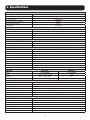 3
3
-
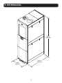 4
4
-
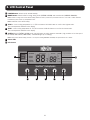 5
5
-
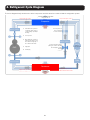 6
6
-
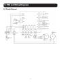 7
7
-
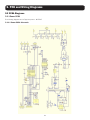 8
8
-
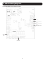 9
9
-
 10
10
-
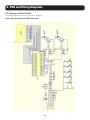 11
11
-
 12
12
-
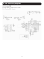 13
13
-
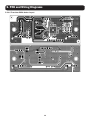 14
14
-
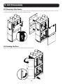 15
15
-
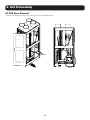 16
16
-
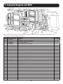 17
17
-
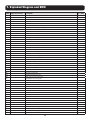 18
18
-
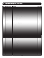 19
19
-
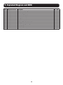 20
20
-
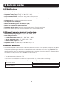 21
21
-
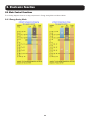 22
22
-
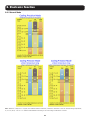 23
23
-
 24
24
-
 25
25
-
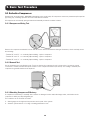 26
26
-
 27
27
-
 28
28
-
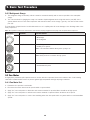 29
29
-
 30
30
-
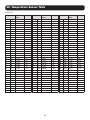 31
31
-
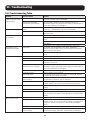 32
32
-
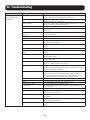 33
33
-
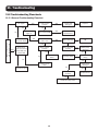 34
34
-
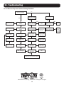 35
35
-
 36
36
-
 37
37
-
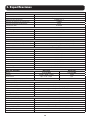 38
38
-
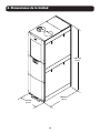 39
39
-
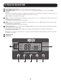 40
40
-
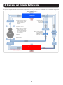 41
41
-
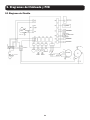 42
42
-
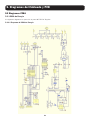 43
43
-
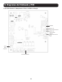 44
44
-
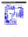 45
45
-
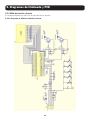 46
46
-
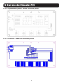 47
47
-
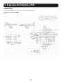 48
48
-
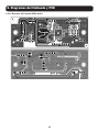 49
49
-
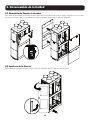 50
50
-
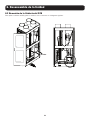 51
51
-
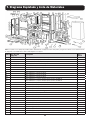 52
52
-
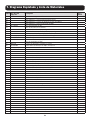 53
53
-
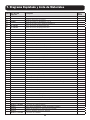 54
54
-
 55
55
-
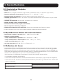 56
56
-
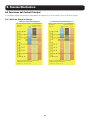 57
57
-
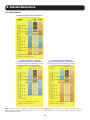 58
58
-
 59
59
-
 60
60
-
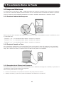 61
61
-
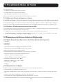 62
62
-
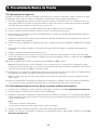 63
63
-
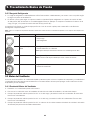 64
64
-
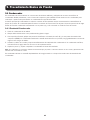 65
65
-
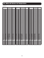 66
66
-
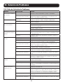 67
67
-
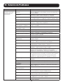 68
68
-
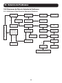 69
69
-
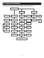 70
70
-
 71
71
-
 72
72


en otros idiomas
- English: Tripp Lite SRCOOL33K User manual
Artículos relacionados
-
Tripp Lite SRXCOOL33K Manual de usuario
-
Tripp Lite SRCOOL33K El manual del propietario
-
-
-
Tripp Lite SRCOOL33K/SRXCOOL33K Air Conditioning Unit El manual del propietario
-
-
Otros documentos
-
 Koldwave 5WK14 Installation, Operating And Maintenance Manual
-
 COOLRUN MUNICAP200 Guía de instalación
-
UEi DMG150 El manual del propietario
-
OutBack Power FXR / VFXR A Series El manual del propietario
-
 JB ELIMINATOR DV-6E-250SP Manual de usuario
-
Yellow Jacket Digital LCD Economy Vacuum Gauge Manual de usuario
-
Vemer EVA-4DIN 1A DC Manual de usuario
-
-
 Olimpia Splendid Sherpa AQUADUE S2 Manuale d'installazione
-
Intermatic DDT40 Instrucciones de operación


