
Quick‐
start
2006/42/EC
NO
SAFETY
Power supply: Class 2
UL Environmental Rating: Enclosure Type 1
8008782:
Q U I C K S T A R T d e
en:
These instructions are only valid in combination with the 8008782 operating
instructions. The operating instructions are available at www.sick.com.
There may be additional relevant specifications for the WS/WE24-2xxxxSxx
devices. These can be found in the operating instructions.
Mounting, connection, and configuration should only be performed by trained spe‐
cialists.
This device is not a safety component in accordance with the EU Machinery Direc‐
tive.
Do not install the sensor at locations that are exposed to direct sunlight or other
weather influences, unless this is expressly permitted in the operating instruc‐
tions.
de:
Diese Anleitung ist ausschließlich in Verbindung mit der Betriebsanleitung
8008782 gültig. Die Betriebsanleitung finden Sie unter www.sick.com.
Für die Geräte WS/WE24-2xxxxSxx kann es weitere, für die Inbetriebnahme rele‐
vante Angaben geben. Diese finden Sie in der Betriebsanleitung.
Anschluss, Montage und Einstellung nur durch Fachpersonal.
Kein Sicherheitsbauteil gemäß EU-Maschinenrichtlinie.
Installieren Sie den Sensor nicht an Orten, die direkter Sonneneinstrahlung oder
sonstigen Wettereinflüssen ausgesetzt sind, ausser dies ist in der Betriebsanlei‐
tung ausdrücklich erlaubt.
it:
Le presenti istruzioni sono valide solo in abbinamento alle istruzioni per l'uso
8008782. Le istruzioni per l'uso sono reperibili su www.sick.com.
Per i dispositivi WS/WE24-2xxxxSxx esistono ulteriori dati rilevanti per la messa in
servizio. Sono riportati nelle istruzioni per l'uso.
Collegamento, montaggio e regolazione solo a cura di personale tecnico specializ‐
zato.
Nessun componente di sicurezza ai sensi della direttiva macchine UE.
Non installare il sensore in luoghi esposti all'irraggiamento solare diretto o ad altri
influssi meteorologici, se non espressamente consentito nelle istruzioni per l'uso.
fr :
Cette notice n'est valable qu'avec la notice d'instruction 8008782. La notice
d'instruction est disponible sur le site Internet www.sick.com.
Pour les appareils WS/WE24-2xxxxSxx, il peut y avoir d’autres indications import‐
antes pour la mise en service. Vous les trouverez dans la notice d'instruction.
Confier le raccordement, le montage et le réglage uniquement au personnel qua‐
lifié.
Il ne s'agit pas d'un composant de sécurité au sens de la directive machines CE.
N’installez pas le capteur à des endroits directement exposées aux rayons du
soleil ou à d’autres conditions météorologiques, sauf si cela est explicitement
autorisé dans la notice d'instruction.
es:
Estas instrucciones solo son válidas junto con las instrucciones de uso 8008782.
Puede encontrar las instrucciones de uso en www.mysick.com.
Para los dispositivos WS/WE24-2xxxxSxx puede haber más información relevante
para la puesta en servicio. La encontrará en las instrucciones de uso.
La conexión, el montaje y el ajuste deben efectuarlos exclusivamente técnicos
especialistas.
No se trata de un componente de seguridad según la Directiva de máquinas de la
UE.
No instale el sensor en lugares directamente expuestos a la radiación solar o a
otras influencias climatológicas, salvo si las instrucciones de uso lo permiten
expresamente.
zh:
本说明书仅在结合使用 8008782 操作指南情况下有效。查看操作指南可访问
www.sick.com 网页。
针对设备 WS/WE24-2xxxxSxx 可能还有更多与调试相关的说明。请参考操作指
南对其进行查阅。
仅允许由专业人员进行接线、安装和设置。
本设备非欧盟机械指令中定义的安全部件。
请勿将传感器安装在阳光直射或受其它气候影响的位置,除非操作指南中明确
允许这一行为。
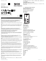
1 Operating and status indicators
Bedien- und Anzeigeelemente
Elementi di comando e di visualizzazione
Éléments de commande et d'affichage
Elementos de mando y visualización
操作及显示元件
t
2
t
2
t
1
t
1
t
1
+ t
2
t
0
PNP
NPN
D
H
1
2
3
5
4
1 WE24-2xxxx:
Yellow LED indicator
Gelbe Anzeige LED
Indicatori LED gialli
LED d'affichage jaune
LED indicador amarillo
黄色 LED 指示灯
2 WE24-2xxxx:
Potentiometer: sensitivity adjustment
Potentiometer: Einstellung der Empfindlichkeit
Potenziometro: impostazione della sensibilità
Potentiomètre : réglage de la sensibilité
Potenciómetro: ajuste de la sensibilidad
电位计:用于调节灵敏度
3 WE24-2xxxx:
Switch: light (L) / dark (D)
Schalter: hell (H) / dunkel (D)
Commutatore: funzionamento light on (H) / dark on (D)
Commutateur : clair (C) / sombre (S)
Conmutador: claro (H) / oscuro (D)
开关:亮 (H) / 暗 (D)
4 WE24-2Bxxx, WE24-2Vxxx:
Switch: NPN / PNP
Schalter: NPN / PNP
Commutatore: NPN / PNP
Commutateur : NPN / PNP
Conmutador: NPN / PNP
开关:NPN / PNP
5 WE24-2xx4x:
Potentiometer: time function adjustment
Potentiometer: Einstellung der Zeitfunktionen
Potenziometro: impostazione delle funzioni temporali
Potentiomètre : réglage des fonctions temporelles
Potenciómetro: ajuste de las funciones de temporización
电位计:用于调节时间功能
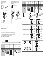
2 Mounting
Montage
Montaggio
Montage
Montaje
安装
8020834.11NZ / 26.03.2019/de WS/WE24-2 | SICK 1
8020834.11NZ / 26.03.2019
www.sick.com
WS/WE24-2
SICK AG
E
rwin-Sick
-Straße 1
D-79183 Waldkirch

Tightening torque
Anzugsdrehmoment
Coppia di serraggio
Couple de serrage
Par de apriete
拧紧力矩
Ambient temperature in operation
Umgebungstemperatur im Betrieb
Temperatura ambiente nell'esercizio
Température ambiante en service
Temperatura ambiente durante el funcio‐
namiento
运行环境温度
< 2 Nm
–40°C ... +60 °C
–40°F ... +140 °F
WS/WE24-2x3x3, -2x4x0, -2x5x0 -2x2x0
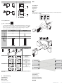
3 Electrical installation
Elektrische Installation
Installazione elettrica
Installation électrique
Instalación eléctrica
电气安装
The sensors must be connected in a voltage-free state.
Anschluss der Sensoren muss spannungsfrei erfolgen.
Il collegamento dei sensori deve avvenire in assenza di tensione.
Le raccordement des capteurs doit s'effectuer hors tension.
Los sensores deben conectarse sin tensión.
必须在无电压状态 连接传感器。
3.1 WS/WE24-2Bxxx, WS/WE24-2Vxxx
U
B
: 10 ... 30 V DC
1
1
U
i
= 250 V: Rated insulation voltage / Bemessungsisolationsspannung / Tensione nomi‐
nale di isolamento / Tension d‘isolation / Tensión nominal de aislamiento / 額定絕緣電
壓
WS24-2 D3x3 D2x0 D4x0 D5x0
1 + (L+) + (L+) + (L+) + (L+)
2 - (M) - (M) Test Test
3 Test - - (M) - (M)
4 - - n.c. n.c.
5 - Test - n.c.
I
N
= 4 A
1 2 3 4 5
0.14 ... 1.5 mm
2
I
N
= 4 A
1
2
4 3
1
2
5
4 3
WE24-2 B3x3 B2x0 B4x0 V5x0
1 + (L+) + (L+) + (L+) + (L+)
2 - (M) - (M) n.c. n.c.
3
Q/Q
- - (M) - (M)
4 -
Q/Q Q/Q Q/Q
5 - - - Alarm
I
N
= 4 A
1 2 3 4 5
0.14 ... 1.5 mm
2
I
N
= 4 A
1
2
4 3
1
2
5
4 3
H
D
3
NPN
PNP
4
H, PNP: Q/Q (≤ 100 mA)
+ (L+)
Q/Q
– (M)
+ (L+)
Q/Q
– (M)
D, PNP: Q/Q (≤ 100 mA)
+ (L+)
Q/Q
– (M)
+ (L+)
Q/Q
– (M)
H, NPN: Q/Q (≤ 100 mA)
+ (L+)
Q/Q
– (M)
+ (L+)
Q/Q
– (M)
D, NPN: Q/Q (≤ 100 mA)
+ (L+)
Q/Q
– (M)
+ (L+)
Q/Q
– (M)
Alarm (≤ 100 mA)
+ (L+)
Alarm
– (M)
+ (L+)
Alarm
– (M)
8020834.11NZ / 26.03.2019/de WS/WE24-2 | SICK 2

Test
+ (L+)
Test
– (M)
+ (L+)
Test
– (M)
3.2 WS/WE24-2Rxxx
U
B
: 20 V ... 250 V AC/DC
1
1
U
i
= 250 V: Rated insulation voltage / Bemessungsisolationsspannung / Tensione nomi‐
nale di isolamento / Tension d‘isolation / Tensión nominal de aislamiento / 額定絕緣電
壓
AC-15, DC-13 (EN 60947-1): Utilization category/ Gebrauchskategorie / Categoria
d'uso / Catégorie d'emploi / Categoría de uso / 使用类别
WS24-2U2x0 WE24-2R2x0
1 L1 / + L1 / +
2 N / - N / -
3 - Relay
4 - Relay
5 - Relay
1 2 3 4 5
0.14 ... 1.5 mm
2
1 2 3 4 5
0.14 ... 1.5 mm
2
Relay
H
D
3
WE24-2R2x0
H
3
4
5
3
4
5
I
max.
= 4A@250V AC
4A@24V DC
0.125A@250 V DC
UL: 4A @ 250 V AC, gene‐
ral use
4A @ 250 V AC, resistive
(NO)
3A @ 250 V AC, resistive
(NC)
4A @ 24 V DC, NO, general
use
3A @ 24 V DC, NC, general
use
R300
B300 (NO contacts only)
D
3
4
5
3
4
5
WE24-2R5x8, WE24-2R5x9: I
max.
= 2.5 A @ 250 V AC, 2.5 A @ 24 V DC, 0.125 A
@250 VDC
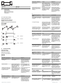
4 Commissioning
Inbetriebnahme
Messa in servizio
Mise en service
Puesta en servicio
调试
4.1 Alignment
Ausrichtung
Orientamento
Alignement
Alineación
校准
Visible red light / sichtbares Rotlicht / luce rossa visibile / Lumière rouge visible /
Luz roja visible / 可见红光
Receiver (WE)
Receiver (WE)
Sender (WS)
Sender (WS)
Sender (WS)
Receiver (WE)
4.2 Sensing range
Schaltabstand
Distanza di lavoro
Distance de commutation
Distancia de conmutación
感应距离
8020834.11NZ / 26.03.2019/de WS/WE24-2 | SICK 3

1
WS/WE24-2 xx3x, xx4x
1
0 ... 50 m
1
Sensing range
Schaltabstand
Distanza di lavoro
Distance de commutation
Distancia de conmutación
触发感应距离
4.3 Time function setting
Einstellung Zeitfunktionen
Regolazione funzioni temporali
Réglage fonctions temporelles
Ajuste de las funciones de temporización
时间功能设置
WE24-2xx4x
0
1 2
+
0.5 ... 10 sec.
0.5 ... 10 sec.
0.5 ... 10 sec.
5 Troubleshooting
Störungsbehebung
Eliminazione difetti
Élimination des défauts
Resolución de problemas
故障排除
en:
LED indicator/fault pattern Cause Measures
No object in beam path, no
output signal
Test input (Test) is not con‐
nected properly
Check connection of the test
input. When using female
cable connectors with LED
indicators, make sure the
test input is assigned corre‐
spondingly.
Yellow LED flashes Distance between sender
(WS) and receiver (WE) is too
large / Beam of WS is not
completely on WE or WE is
not aligned to WS
Check sensing range, see
4.2 / Check alignment, see
4.1 / Potentiometer must be
at "max."
Yellow LED does not light up,
output signal is present even
though there is no object in
the path of the beam
The beam of light of a photo‐
electric through-beam sensor
hits the receiver of another
(neighboring) photoelectric
through-beam sensor
Swap the sender and receiver
arrangement at every
second photo‐
electric through-beam sensor
and ensure that there is suffi‐
cient distance between the
through-beam photoelectric
sensors, see 4.1
de:
Anzeige-LED / Fehlerbild Ursache Maßnahme
Kein Objekt im Strahlengang,
kein Ausgangssignal
Testeingang (Test) ist nicht
korrekt angeschlossen
Anschluss des Testeingangs
prüfen. Bei Verwendung von
Leitungsdosen mit LED-
Anzeigen ist darauf zu ach‐
ten, dass der Testeingang
entsprechend belegt wird.
Anzeige-LED / Fehlerbild Ursache Maßnahme
gelbe LED blinkt Abstand zwischen Sender
(WS) und Empfänger (WE) ist
zu groß / Lichtstrahl von WS
ist nicht vollständig auf WE
bzw. WE ist nicht auf WS aus‐
gerichtet
Schaltabstand prüfen, siehe
4.2 / Ausrichtung prüfen,
siehe 4.1 / Potentiometer
muss auf "Max." stehen
gelbe LED leuchtet nicht, Aus‐
gangssignal ist vorhanden,
obwohl kein Objekt im Strah‐
lengang ist
Der Lichtstrahl einer Einweg-
Lichtschranke trifft auf den
Empfänger einer anderen
(benachbarten) Einweg-
Lichtschranke
Bei jeder zweiten Einweg-
Lichtschranke die Anordnung
von Sender und Empfänger
tauschen, bzw. genügend
Abstand zwischen den Ein‐
weg-Lichtschranken einhal‐
ten, siehe 4.1
it:
Indicatore LED / figura di
errore
Causa Provvedimento
Nessun oggetto nella traietto‐
ria del raggio, nessun segnale
in uscita
L'entrata di prova (Test) non
è collegata correttamente
Controllare il collegamento
dell'entrata di test. Per l'uti‐
lizzo di connettori femmina
precablati con indicatori LED
si deve prestare attenzione
che l'entrata di test sia ade‐
guatamente occupata.
il LED giallo lampeggia Distanza eccessiva tra emet‐
titore (WS) e ricevitore (WE) /
Il raggio luminoso dell'emet‐
titore (WS) non è completa‐
mente allineato al ricevitore
(WE) o viceversa
Controllare la distanza di
lavoro, vedere 4.2 / Control‐
lare l'allineamento, vedere
4.1 / Il potenziometro deve
essere impostato su "Max."
Il LED giallo non è acceso, il
segnale in uscita è presente,
ma nessun oggetto si trova
nella traiettoria del raggio
Il fascio di luce dell'emetti‐
tore colpisce il ricevitore di
un altro relè fotoelettrico uni‐
direzionale (vicino)
Scambiare la disposizione di
emettitore e ricevitore, o ris‐
pettare una distanza suffici‐
ente fra i relè fotoelettrici,
vedere 4.1
fr :
LED d'état / image du défaut Cause Mesure
Pas d’objet dans la trajectoire
du faisceau, pas de signal de
sortie
L'entrée test (Test) n'est pas
correctement raccordée
Contrôler le raccordement de
l'entrée test. Si des connec‐
teurs femelles avec afficha‐
ges LED sont utilisés, s'assu‐
rer que l'entrée test est cor‐
rectement affectée.
La LED jaune clignote Distance entre l'émetteur
(WS) et le récepteur (WE) est
trop grande / Le faisceau
lumineux de WS n’est pas
entièrement aligné sur WE
respectivement WE n’est pas
aligné sur WS
Vérifier la distance de com‐
mutation, voir 4.2 / Vérifier
l’alignement, voir 4.1 / Le
potentiomètre doit être réglé
sur « Max. »
la LED jaune ne s'allume pas,
aucun signal de sortie, alors
qu'il n’y a aucun objet dans la
trajectoire du faisceau
Le faisceau lumineux d'une
barrière émetteur-récepteur
atteint le récepteur d'une
autre barrière émetteur-
récepteur (voisine)
Pour une barrière émetteur-
récepteur sur deux, intervertir
la place de l'émetteur et du
récepteur ou laisser suffi‐
samment d'espace entre les
barrières émetteur-récep‐
teur, voir 4.1
es:
LED indicador / imagen de
error
Causa Acción
Ningún objeto en la trayecto‐
ria del haz, sin señal de salida
La entrada de prueba (Test)
no está correctamente
conectada
Verificar la conexión de la
entrada de prueba. Si se
usan tomas de red con indi‐
cadores LED, se debe prestar
atención a que la entrada de
prueba esté ocupada de
forma correspondiente.
El LED amarillo parpadea La distancia entre el emisor
(WS) y el receptor (WE) es
excesiva / El haz de luz de
WS no está completamente
alineado con WE o WE no
está alineado con WS
Comprobar la distancia de
conmutación, véase 4.2 /
Comprobar la alineación,
véase 4.1 / El potenciómetro
debe estar en la posición
"Max."
El LED amarillo no se ilumina,
hay señal de salida pero no
hay ningún objeto en la
trayectoria del haz
El haz de luz de una barrera
fotoeléctrica monohaz incide
sobre el receptor de otra bar‐
rera fotoeléctrica monohaz
(vecina)
Cada dos barreras
fotoeléctricas monohaz,
cambiar la disposición de
transmisores y receptores o
mantener una distancia sufi‐
ciente entre ellas, véase 4.1
zh:
LED 指示灯 / 故障界面 原因 措施
光路中无物体,无输出信号 未正确连接测试输入端 (Test) 检查测试输入端接口。在使用
带 LED 指示灯的电缆插口时
须注意,测试输入端应进行相
应的分配。
黄色 LED 闪烁 发射器 (WS) 和接收器 (WE)
之间的距离过大 / WS 光束未
完全对准 WE 或 WE 未对准
WS
检查触发感应距离,见 4.2 /
检查对准状态,见 4.1 / 电位
计须调至最大
黄色 LED 未亮起,有输出信
号,尽管光路中无物体
某个单向光栅的光束照射到另
一个(相邻)单向光栅的接收
器上
每隔一个单向光栅即交换发射
器和接收器的顺序或在各个单
向光栅之间保留足够间距,见
4.1
8020834.11NZ / 26.03.2019/de WS/WE24-2 | SICK 4
-
 1
1
-
 2
2
-
 3
3
-
 4
4


en otros idiomas
- français: SICK WS/WE24-2
- italiano: SICK WS/WE24-2
- Deutsch: SICK WS/WE24-2
Artículos relacionados
-
SICK WL24-2 Quickstart
-
-
-
-
-
-
-
-
-
SICK WT34 Compact photoelectric sensors Instrucciones de operación