NZXT N7 B650E Manual de usuario
- Categoría
- Placas base
- Tipo
- Manual de usuario

N7 B650E
AMD ATX MOTHERBOARD

TABLE OF CONTENTS
SAFETY PRECAUTION ........................................... 01
PACKAGE CONTENTS ................................................ 02
SPECIFICATIONS ....................................................... 03
COVERS ...................................................................... 13
PORTS OVERVIEW ..................................................... 14
REAR I/O .................................................................... 20
CPU SOCKET .............................................................. 22
VERSION 3.3, 2023/04/19

PCIE EXPANSION SLOTS .......................................... 27
SATA CONNECTORS .................................................. 31
M.2 SLOTS FOR STORAGE ........................................ 33
M.2 SLOT FOR WIRELESS CONNECTIVITY ............. 35
ANTENNA ................................................................... 36
POWER CONNECTORS ............................................... 37
DIMM SLOTS .............................................................. 25

FRONT PANEL AUDIO CONNECTOR ......................... 39
FRONT PANEL CONNECTOR ..................................... 40
FAN CONNECTORS .................................................... 41
NZXT RGB CONNECTORS .......................................... 42
5V ADDRESSABLE RGB CONNECTOR ...................... 44
BUTTONS AND POST LEDS ....................................... 46
USB CONNECTORS .................................................... 38

DOWNLOADING NZXT CAM ....................................... 54
NZXT GLOBAL WARRANTY POLICY ....................... 55
REGULATORY NOTICES ............................................ 58
限用物质及元素列表/限用物質及元素清單 ...................... 60
SUPPORT AND SERVICE ........................................... 61
BIOS FLASHBACK ...................................................... 50
CMOS BATTERY ......................................................... 49

01
SAFETY PRECAUTION
PRECAUCIONES DE SEGURIDAD
PRÉCAUTIONS DE SÉCURITÉ
SICHERHEITSVORKEHRUNGEN
PRECAUÇÕES DE SEGURANÇA
Follow these safety precautions when installing the motherboard:
• It is recommended to wear a grounding strap attached to a grounded
device to avoid damage from static electricity.
• Discharge static electricity by touching the metal case of a safely
grounded object before working on the motherboard.
• Leave components in the static-proof bags.
• Always remove the AC power by unplugging the power cord from the
power outlet before installing or removing the motherboard or other
hardware components.
Al instalar la placa base, sigue estas precauciones de seguridad:
• Se recomienda llevar un brazalete antiestático conectado a un dispositivo
de toma de tierra para evitar daños causados por la electricidad estática.
• Antes de empezar a trabajar en la placa base, toca la caja de metal de
un objeto con conexión a tierra segura para descargar la electricidad
estática.
• Deja los componentes en bolsas antiestáticas.
• Desenchufa siempre el cable de alimentación de la toma de corriente
para retirar la alimentación de CA antes de instalar o extraer la placa
base u otros componentes de hardware.
Respectez les précautions de sécurité suivantes lors de l'installation de
la carte mère:
• Il est recommandé de porter un ruban de mise à la terre, attaché à un
dispositif mis à la terre pour éviter les dommages dus à l'électricité
statique.
• Avant de commencer à travailler sur la carte mère, déchargez votre
électricité statique en touchant le boîtier métallique d'un objet mis à la
terre de manière sécurisée.
• Laissez les composants dans les sacs résistants à l'électricité statique.
• Avant d'installer ou retirer la carte mère ou d'autres composants
matériels, retirez toujours le boîtier d'alimentation secteur en
débranchant le câble de la prise.
Beachten Sie die folgenden Sicherheitsvorkehrungen bei der Installation
des Mainboards:
• Zum Schutz vor Schäden durch elektrostatische Entladung wird die
Verwendung eines Antistatikbands empfohlen, das an ein geerdetes Gerät
angeschlossen ist.
• Entladen Sie statische Elektrizität, indem Sie das Metallgehäuse eines
sicher geerdeten Objekts berühren, bevor Sie mit dem Mainboard
arbeiten.
• Bewahren Sie Komponenten stets in den antistatischen Beuteln auf.
• Trennen Sie stets die Stromversorgung, bevor Sie das Mainboad oder
andere Hardwarekomponenten installieren oder entfernen. Ziehen Sie
dazu den Netzstecker aus der Steckdose.
Siga estas precauções de segurança ao instalar a placa-mãe:
• Recomendamos usar um cabo de aterramento conectado a um
dispositivo aterrado para evitar danos causados por eletricidade
estática.
• Descarregue a eletricidade estática tocando na caixa de metal de um
objeto aterrado com segurança antes de trabalhar na placa-mãe.
• Deixe os componentes nas sacolas à prova de estática.
• Sempre remova a energia CA desconectando o cabo de energia
da tomada antes de instalar ou remover a placa-mãe ou outros
componentes de hardware.
마더보드를 설치할 때 다음의 안전 수칙을 준수하십시오:
• 정전기에 의한 부상을 방지하기 위해 접지 장치에 부착된 접지 스트랩 착
용을 권장합니다.
• 마더보드에서 작업하기 전에 안전하게 접지된 물체의 금속 케이스에 접촉
하여 정전기를 방출하십시오.
• 구성품은 “정전기방지백”에 넣어두십시오.
• 마더보드 또는 기타 하드웨어를 설치하거나 제거하기 전 반드시 전원 코
드를 분리하여 AC 전원을 차단하십시오.
•
•
•
• AC
安装主板时,请遵循以下安全防护要求:
• 建议佩戴接地手环并连接接地设备,以避免静电损坏主板。
• 在对主板进行操作前,请触摸已安全接地的设备的金属外壳,以释
放静电。
• 将组件放在防静电袋中。
• 在安装或拆卸主板或其他硬件组件前,请务必将电源线从电源插座上
拔下,断开交流电源。
在安裝主機板時,請遵守這些安全性預防措施:
• 建議佩戴連接至已接地裝置的接地帶,以避免遭受靜電傷害。
• 在對主機板進行作業之前,請觸碰已經安全接地之物品的金屬殼來
釋放靜電。
• 請將元件留置於防靜電袋中。
• 在安裝或拆除主機板或其他硬體元件之前,請務必將電源線從電源插
座拔除以移除 AC 電源。
안전 수칙
安全防护
安全性預防措施

02
PACKAGE CONTENTS
CONTENIDO DEL PAQUETE
CONTENU DE L'EMBALLAGE
LIEFERUMFANG
CONTEÚDO DO PACOTE
AN7 B650E Motherboard
x1
DWireless Antenna
x2
BSATA Cables
90°x2, 180°x2
CM.2 Screws
x3
A .
N7 B650E Mainboard
B .
SATA-Kabel
C .
M.2 Schrauben
D .
Drahtlose Antenne
A.
Placa-mãe N7 B650E
B.
Cabos SATA
C.
PARAFUSOS M.2
D.
Antena sem fio
A .
N7 B650E
B .
SATA
C .
M.2
D .
A .
N7 B650E 主機板
B .
SATA 線
C .
M.2螺絲
D .
無線天線
A .
N7 B650E 主板
B .
SATA 线
C .
M.2 螺丝
D .
无线天线
A .
N7 B650E 메인보드
B .
SATA 케이블
C .
M.2 나사
D .
무선 안테나
A .
Placa base N7 B650E
B .
Cables SATA
C .
Tornillos M.2
D .
Antena inalámbrica
A .
Carte mère N7 B650E
B .
Câbles SATA
C .
Vis M.2
D .
Antenne sans fil
패키지 구성품
包装内容
包裝內容

03
SPECIFICATIONS
ESPECIFICACIONES
CARACTÉRISTIQUES
SPEZIFIKATIONEN
ESPECIFICAÇÕES
CPU & Socket
Supports AMD Socket AM5 Ryzen™ 7000 Series Processors
Chipse AMD B650
Memory
4 x DIMM slots, Max. 128GB, Dual-channel DDR5 Memory Technology
• Supports DDR5 Non-ECC, Un-buffered Memory up to 6000+ (OC)*
• Supports Extreme Memory Profile (XMP) and EXTended Profiles
for Overclocking (EXPO) memory modules
* Supports DDR5 3200 natively
Expansion Slots
CPU
• 1 x PCIe 5.0 ×16 slot (PCIEX16_1), supports ×16 mode*
Chipset
• 2 x PCIe 4.0 ×16 slots (PCIEX16_2 and PCIEX16_3),
support ×2 mode*
• 1 x M.2 Socket (Key E), supports Type 2230
Wi-Fi/BT PCIe Wi-Fi module
* Supports NVMe SSD as boot disks
Integrated Graphics
Integrated AMD RDNA™ 2 graphics (Actual support may vary by CPU)
• 1 x HDMI 2.1 TMD Compatible, supports HDR, HDCP 2.3 and max.
resolution up to 4K 60Hz
Storage
CPU
• 1 x M.2_1, Type 2242/2260/2280 (PCIe 5.0 ×4 mode)*
• 1 x M.2_2, Type 2242/2260/2280 (PCIe 4.0 ×4 mode)*
Chipset
• 1 x M.2_3, Type 2242/2260/2280 (PCIe 4.0 ×2 mode)*
• 4 x SATA 6Gb/s ports
> Support RAID 0/1/10 for SATA storage devices
> Support RAID 0/1/10 for M.2 NVMe storage devices
* Supports NVMe SSD as boot disks
LAN Realtek® RTL8125BG 2.5G LAN
Audio
Realtek® ALC1220 Codec
• Impedance sensing for rear out port
Bluetooth Bluetooth V5.2
Wireless
802.11ax Wi-Fi 6E Module
• Supports IEEE 802.11 a/b/g/n/ac/ax
• Support Dual Band 2x2 with extended 6GHz band support*
• Supports MU-MIMO
• Supports Bluetooth + High speed class II
* Wi-Fi 6E (6GHz band) will be supported by Microsoft® Windows® 11 and
availability may vary by country and region. A 6GHz compatible router is
required for 6E functionality.
Rear I/O
• 2 x Wireless antenna SMA connectors
• 1 x HDMI™ port
• 2 x USB 2.0 ports
• 1 x USB 3.2 Gen 2 Type-C port
• 2 x USB 3.2 Gen 2 ports
• 4 x USB 3.2 Gen 1 ports
• 1 x Clear CMOS button
• 1 x BIOS Flashback button
• 1 x LAN (RJ45) port
• 5 x Audio jacks
• 1 x Optical S/PDIF Out port
Internal I/O
• 1 x 24-pin ATX power connector
• 1 x 8+4-pin ATX 12V power connector
• 1 x 4-pin CPU_FAN connector (Up to 24W per channel)
• 1 x 4-pin AIO_PUMP connector (Up to 24W per channel)
• 5 x 4-pin SYS_FAN connectors (Up to 24W per channel)
• 4 x NZXT RGB LED connectors
• 2 x 5V Addressable RGB LED connector
• 2 x USB 2.0 header (Up to 4 USB 2.0 ports)
• 1 x USB 3.2 Gen 1 header (Up to 2 USB 3.2 Gen 1 ports)
• 1 x USB 3.2 Gen 2x2 front panel header (For USB Type C)
• 1 x Front panel audio connector
• 1 x Power button
• 1 x Reset button
• 4 x POST LEDs
Operating System Microsoft® Windows® 11/10 (64-bit)
Form Factor ATX
System Requirements
• NZXT CAM software requires Microsoft Windows® 11/10 operating system.
• NZXT CAM is free to download and use; some features require a valid email
address, acceptance of our current Terms of Service, and an active internet
connection.
사양
技术规格
產品規格

04
SPECIFICATIONS
ESPECIFICACIONES
CARACTÉRISTIQUES
SPEZIFIKATIONEN
ESPECIFICAÇÕES
Procesador y zócalo
Compatible con el zócalo de AMD para procesadores AM5 Ryzen™ de
la serie 7000
Chipse AMD B650
Memoria
4 ranuras DIMM, máx. 128GB, tecnología de memoria DDR5 de dos
canales
• Compatible con memoria DDR5 no ECC sin búfer de hasta 6000+
(OC)*
• Compatible con módulos de memoria Extreme Memory Profile
(XMP) y EXTended Profiles for Overclocking (EXPO)
* Compatible con DDR5 3200 de forma nativa
Ranuras de expansión
Procesador
• 1 ranura PCIe 5.0 ×16 (PCIEX16_1), compatible con modo ×16*
Chipset
• 2 ranuras PCIe 4.0 ×16 (PCIEX16_2 y PCIEX16_3), compatibles
con modo ×2*
• 1 zócalo M.2 (clave E), compatible con módulo wifi PCIe wifi/BT
de tipo 2230
* Compatible con SSD NVMe como discos de arranque
Gráficos integrados
Arquitectura gráfica AMD RDNA™ 2 integrada
(compatibilidad real en función del procesador)
• 1 HDMI 2.1 compatible con TMD, admite HDR, HDCP 2.3 y una
resolución máx. de 4K a 60Hz
Almacenamiento
Procesador
• 1 M.2_1 de tipo 2242/2260/2280 (modo PCIe 5.0 ×4)*
• 1 M.2_2 de tipo 2242/2260/2280 (modo PCIe 4.0 ×4)*
Chipset
• 1 M.2_3 de tipo 2242/2260/2280 (modo PCIe 4.0 ×2)*
• 4 puertos SATA de 6Gb/s
> Compatible con RAID 0/1/10 para dispositivos de almacenamiento
SATA
> Compatible con RAID 0/1/10 para dispositivos de almacenamiento
NVMe M.2
* Compatible con SSD NVMe como discos de arranque
LAN LAN Realtek® RTL8125BG 2,5G
Audio
Realtek® ALC1220 Codec
• Impedance sensing for rear out port
Bluetooth Bluetooth V5.2
Conectividad inalámbrica
Módulo wifi 6E 802.11ax
• Compatible con IEEE 802.11 a/b/g/n/ac/ax
• Compatible con doble banda 2×2 con ampliación de 6GHz*
• Compatible con MU-MIMO
• Compatible con Bluetooth + alta velocidad clase II
* La wifi 6E (banda de 6GHz) será compatible con Microsoft® Windows®11 y
su disponibilidad puede variar según el país y la región. Para disfrutar de la
funcionalidad 6E, se necesita un rúter compatible con la banda de 6GHz.
Entradas y salidas traseras
• 2 x conectores SMA de antena inalámbrica
• 1 x puerto HDMI™
• 2 x puertos USB 2.0
• 1 x puerto USB 3.2 Gen 2 de tipo C
• 2 x puertos USB 3.2 Gen 2
• 4 x puertos USB 3.2 Gen 1
• 1 x botón de vaciado de CMOS
• 1 x botón BIOS Flashback
• 1 x puerto LAN (RJ45)
• 5 x jacks de audio
• 1 x puerto de salida óptica S/PDIF
Interfaces de E/S internas
• 1 x conector de alimentación ATX de 24 patillas
• 1 x conector de alimentación ATX de 12 V y 8+4 patillas
• 1 x conector CPU_FAN de 4 patillas (Up to 24W per channel)
• 1 x conector AIO_PUMP de 4 patillas (Up to 24W per channel)
• 5 x conectores SYS_FAN de 4 patillas (Up to 24W per channel)
• 4 x conectores de NZXT RGB LED
• 2 x conectore de 5V ARGB LED
• 2 x cabezales USB 2.0 (admiten hasta 4 puertos USB 2.0)
• 1 x cabezale USB 3.2 Gen 1 (admiten hasta 2 puertos USB 3.2 Gen 1)
• 1 x cabezale USB 3.2 Gen 2x2 (Para USB Type C)
• 1 x conector de audio de panel frontal
• 1 x botón de encendido
• 1 x botón de restablecimiento
• 4 x postes LED
Sistema operativo Microsoft® Windows® 11/10 de 64 bits
Diseño ATX
Requisitos del sistema
• El software NZXT CAM requiere el sistema operativo Microsoft Windows®
11/10.
• La descarga y el uso de NZXT CAM son gratuitos; algunas funciones
requieren una dirección de correo electrónico válida, la aceptación de
nuestros Términos de servicio actuales y una conexión a Internet activa.
사양
技术规格
產品規格

05
SPECIFICATIONS
ESPECIFICACIONES
CARACTÉRISTIQUES
SPEZIFIKATIONEN
ESPECIFICAÇÕES
Processeur et socket
Compatible avec la plateforme AM5 des processeurs AMD Ryzen™
Séries7000
Jeu de puces AMD B650
Mémoire
4 x logements DIMM, maxi. 128Go, technologie de mémoire DDR5
double canal
• Compatible avec une mémoire DDR5 non-ECC, sans mémoire
tampon jusqu’à6000+ (OC)*
• Compatible avec les modules de mémoire Extreme Memory
Profile (XMP) et EXTended Profiles for Overclocking (EXPO)
* Compatible avec DDR53200 nativement
Logements pour extension
PROCESSEUR
• 1 x logement PCIe 5.0 ×16 (PCIEX16_1),
compatible avec le mode ×16*
Jeu de puces
• 2 x PCIe 4.0 ×16 logements (PCIEX16_2 et PCIEX16_3),
compatible avec le mode ×2*
• 1 x socket M.2 (clé E), compatible avec module PCIe Wi-Fi de type
2230 Wi-Fi/BT
* Compatible avec NVMe SSD comme disques de démarrage
Composants graphiques intégrés
Composants graphiques AMD RDNA™ 2 intégrés
(le support réel peut varier selon le processeur)
• 1 x HDMI 2.1 compatible TMD, compatible avec HDR, HDCP 2.3 et
résolution maxi. de 4K 60Hz
Stockage
PROCESSEUR
• 1 x M.2_1, type 2242/2260/2280 (mode PCIe 5.0 ×4)*
• 1 x M.2_2, type 2242/2260/2280 (mode PCIe 4.0 ×4)*
Jeu de puces
• 1 x M.2_3, type 2242/2260/2280 (mode PCIe 4.0 ×2)*
• 4 x ports SATA 6Go/s
> Compatible avec RAID 0/1/10 pour périphériques de stockage SATA
> Compatible avec RAID 0/1/10 pour périphériques de stockage M.2
NVMe
* Compatible avec NVMe SSD comme disques de démarrage
LAN LAN Realtek® RTL8125BG 2,5Go
Audio
Codec Realtek® ALC1220
• Détection d'impédance pour le port de sortie arrière
Bluetooth Bluetooth V5.2
Sans fil
Module 802.11ax Wi-Fi 6E
• Compatible IEEE 802.11 a/b/g/n/ac/ax
• Support bibande 2x2 avec compatibilité bande 6GHz d’extension*
• Compatible MU-MIMO
• Compatible Bluetooth + classe2 haut débit
* Wi-Fi 6E (bande de 6GHz) pris en charge par Microsoft® Windows®11; la
disponibilité peut varier en fonction du pays et de la région. Un routeur de
6GHz est requis pour la fonctionnalité 6E.
E/S arrière
• 2 x connecteurs SMA pour antenne sans fil
• 1 x port HDMI™
• 2 x ports USB 2.0
• 1 x port USB 3.2 typeC gén.2
• 2 x ports USB 3.2 gén.2
• 4 x ports USB 3.2 gén.1
• 1 x bouton d’effacement du CMOS
• 1 x bouton BIOS Flashback
• 1 x port LAN (RJ45)
• 5 x prises audio
• 1 x port de sortie optique S/PDIF
E/S internes
• 1 x connecteur d'alimentation ATX à 24 broches
• 1 x connecteur d'alimentation ATX 12 V à 8+4 broches
• 1 x connecteur CPU_FAN à 4 broches (Up to 24W per channel)
• 1 x connecteur AIO_PUMP à 4 broches (Up to 24W per channel)
• 5 x connecteurs SYS_FAN à 4 broches (Up to 24W per channel)
• 4 x connecteurs NZXT RGB LED
• 2 x connecteur 5V ARGB LED
• 2 x têtes de bande USB 2.0 (prise en charge de 4 ports USB 2.0 maximum)
• 1 x tête de bande USB 3.2 Gen 1
(prise en charge de 2 ports USB 3.2 Gen 1 maximum)
• 1 x tête de bande USB 3.2 Gen 2x2 front panel (Pour USB Type C)
• 1 x connecteur audio pour panneau avant
• 1 x bouton marche
• 1 x bouton de réinitialisation
• 4 x LED de poste
Système d'exploitation Microsoft® Windows® 11/10 (64-bit)
Format ATX
Configuration requise
• Le logiciel NZXT CAM nécessite le système d'exploitation Microsoft
Windows®11/10.
• NZXT CAM est téléchargeable et utilisable gratuitement; certaines
fonctionnalités nécessitent une adresse e-mail valide, l'acceptation de nos
conditions de service, et une connexion internet active.
사양
技术规格
產品規格

06
SPECIFICATIONS
ESPECIFICACIONES
CARACTÉRISTIQUES
SPEZIFIKATIONEN
ESPECIFICAÇÕES
CPU und Sockel
Unterstützt AMD-Prozessoren der Serie Ryzen™ 7000 mit Sockel
AM5
Chipsatz AMD B650
Arbeitsspeicher
4 DIMM-Slots, max. 128GB, Dual-Channel DDR5-Arbeitsspeicher
• Unterstützt DDR5 Non-ECC, ungepufferten Arbeitsspeicher bis
zu 6000+ (OC)*
• Unterstützt Speichermodule der Typen Extreme Memory Profile
(XMP) und EXTended Profiles for Overclocking (EXPO)
* Unterstützt nativ DDR5 3200
Erweiterungssteckplätze
CPU
• 1 x PCIe 5.0 ×16-Steckplatz (PCIEX16_1), unterstützt
×16-Modus*
Chipsatz
• 2 x PCIe 4.0 ×16-Steckplätze (PCIEX16_2 und PCIEX16_3),
unterstützt ×2-Modus*
• 1 x M.2-Sockel (Key E), unterstützt WLAN-Modul Typ 2230 Wi-Fi/
BT PCIe
* Unterstützt NVMe-SSD als Boot-Disks
Integrierte Grafik
Integrierte AMD RDNA™2-Grafik
(tatsächliche Unterstützung kann je nach CPU abweichen)
• 1 x HDMI 2.1 TMD-kompatibel, unterstützt HDR, HDCP 2.3 und
max. Auflösung bis 4K bei 60Hz
Speicher
CPU
• 1 x M.2_1, Typ 2242/2260/2280 (PCIe 5.0 ×4-Modus)*
• 1 x M.2_2, Typ 2242/2260/2280 (PCIe 4.0 ×4-Modus)*
Chipsatz
• 1 x M.2_3, Typ 2242/2260/2280 (PCIe 4.0 ×2-Modus)*
• 4 x SATA 6Gbit/s-Anschlüsse
> Unterstützt RAID 0/1/10 bei SATA-Speichergeräten
> Unterstützt RAID 0/1/10 bei M.2 NVMe-Speichergeräten
* Unterstützt NVMe-SSD als Boot-Disks
Netzwerk Realtek® RTL8125BG 2,5G LAN
Audio
Realtek® ALC1220 Soundkarte
• Impedanzerkennung für hinteren Ausgang
Bluetooth Bluetooth V5.2
WLAN
802.11ax Wi-Fi 6E-Modul
• Unterstützt IEEE 802.11 a/b/g/n/ac/ax
• Unterstützt Dual Band 2x2 mit erweiterter 6-GHz-Band-Unterstützung*
• Unterstützt MU-MIMO
• Unterstützt Bluetooth + High Speed ClassII
* Wi-Fi 6E (6-GHz-Band) wird von Microsoft® Windows® 11 unterstützt.
Die Verfügbarkeit kann je nach Land und Region variieren. Für die
6E-Funktionalität ist ein 6-GHz-kompatibler Router erforderlich.
I/O-Anschlüsse auf der Rückseite
• 2 x SMA-Steckverbinder für Wireless-Antenne
• 1 x HDMI™-Anschluss
• 2 x USB 2.0-Anschlüsse
• 1 x USB 3.2 Gen 2 Typ-C-Anschluss
• 2 x USB 3.2 Gen 2-Anschlüsse
• 4 x USB 3.2 Gen 1-Anschlüsse
• 1 x Clear CMOS-Taste
• 1 x BIOS-Flashback-Taste
• 1 x LAN (RJ45)-Anschluss
• 5 x Audiobuchsen
• 1 x Optischer S/PDIF Out-Anschluss
Interne Anschlüsse
• 1 x 24-poliger ATX-Stromanschluss
• 1 x 8+4-poliger ATX12V-Stromanschluss
• 1 x 4-poliger Anschluss CPU_FAN (Bis zu 24W pro Kanal)
• 1 x 4-poliger Anschluss AIO_PUMP (Bis zu 24W pro Kanal)
• 5 x 4-polige Anschlüsse SYS_FAN (Bis zu 24W pro Kanal)
• 4 x NZXT RGB LED-Anschlüsse
• 2 x 5V ARGB LED-Anschlüsse
• 2 x USB 2.0 header (Unterstützung von bis zu 4 USB 2.0-Anschlüssen)
• 1 x USB 3.2 Gen 1 header
(Unterstützung von bis zu 2 USB 3.2 Gen 1-Anschlüssen)
• 1 x USB 3.2 Gen 2x2 front panel header (For USB Type C)
• 1 x Audioanschluss an der Vorderseite
• 1 x Netzschalter
• 1 x Reset-Taste
• 4 x Post-LEDs
Betriebssystem Microsoft® Windows® 11/10 (64-bit)
Formfaktor ATX
Systemvoraussetzungen
• NZXT CAM-Software erfordert ein Microsoft Windows® 11/10-Betriebssystem.
• Das Herunterladen und die Verwendung von NZXT CAM sind kostenlos;
bestimmte Funktionen erfordern eine gültige E-Mail-Adresse, die Zustimmung
zu unseren aktuellen Servicebedingungen und einen Internetzugang.
사양
技术规格
產品規格

07
SPECIFICATIONS
ESPECIFICACIONES
CARACTÉRISTIQUES
SPEZIFIKATIONEN
ESPECIFICAÇÕES
CPU e encaixe
Suporta processadores AMD Ryzen™ Série 7000 com encaixe AM5
Chipset AMD B650
Memória
4 x Ranhuras DIMM, máx. 128GB, tecnologia de memória de canal
duplo DDR5
• Suporta memória DDR5, não-ECC, sem buffer, até 6000+ (OC)*
• Suporta módulos de memória Extreme Memory Profile (XMP) e
EXTended Profiles for Overclocking (EXPO)
* Suporte nativo de DDR5 3200
Ranhuras de expansão
CPU
• 1 x Ranhura PCIe 5.0 ×16 (PCIEX16_1), suporta modo x16*
Chipset
• 2 x Ranhuras PCIe 4.0 ×16 (PCIEX16_2 e PCIEX16_3), suportam
modo x2*
• 1 x Encaixe M.2 (chave E), suporta módulo Wi-Fi/BT PCIe Wi-Fi
do tipo 2230
* Suporta SSD NVMe como discos de arranque
Gráficos integrados
Gráficos AMD RDNA™ 2 integrados
(o suporte real pode variar consoante o CPU)
• 1 x HDMI 2.1 compatível com TMD, suporta HDR, HDCP 2.3 e
resolução máx. de até 4K 60Hz'
Armazenamento
CPU
• 1 x M.2_1, tipo 2242/2260/2280 (modo PCIe 5.0 ×4)*
• 1 x M.2_2, tipo 2242/2260/2280 (modo PCIe 4.0 ×4)*
Chipset
• 1 x M.2_3, tipo 2242/2260/2280 (modo PCIe 4.0 ×2)*
• 4 x Portas SATA 6Gb/s
> Suportam RAID 0/1/10 para dispositivos de armazenamento SATA
> Suportam RAID 0/1/10 para dispositivos de armazenamento M.2
NVMe
* Suporta SSD NVMe como discos de arranque
LAN LAN Realtek® RTL8125BG 2,5G
Áudio
Codec Realtek® ALC1220
• Sensor de impedância para a porta de saída traseira
Bluetooth Bluetooth V5.2
Wireless
Módulo 802.11ax Wi-Fi 6E
• Suporta IEEE 802.11 a/b/g/n/ac/ax
• Suporta banda dupla 2x2 com suporte alargado à banda de 6GHz*
• Suporta MU-MIMO
• Suporta Bluetooth + High Speed classe II
* O Wi-Fi 6E (banda de 6GHz) será suportado pelo Microsoft® Windows® 11 e
a disponibilidade poderá variar consoante o país e a região. É necessário um
router compatível com 6GHz para a funcionalidade 6E.
Entrada/saída traseira
• 2 x Conectores SMA de antena wireless
• 1 x Porta HDMI™
• 2 x Portas USB 2.0
• 1 x Porta USB 3.2 Ger 2 Tipo C
• 2 x Portas USB 3.2 Ger 2
• 4 x Portas USB 3.2 Ger 1
• 1 x Botão de limpeza da CMOS
• 1 x Botão de BIOS Flashback
• 1 x Porta LAN (RJ45)
• 5 x Conectores áudio
• 1 x Porta de saída ótica S/PDIF
E/S interna
• 1 x conector de energia ATX de 24 pinos
• 1 x conector de energia de 12V ATX de 8+4 pinos
• 1 x conector CPU_FAN de 4 pinos (até 24 W para cada canal)
• 1 x conector AIO_PUMP de 4 pinos (até 24W para cada canal)
• 5 x conectores SYS_FAN de 4 pinos (até 24W para cada canal)
• 4 x conectores LED RGB NZXT
• 2 x conector LED RGB 5V endereçável
• 2 x cabeçote USB 2.0 (até 4 portas USB 2.0)
• 1 x cabeçote USB 3.2 Gen 1 (até 4 portas USB 3.2 Gen 1)
• 1 x cabeçote USB 3.2 Gen 2x2 no painel frontal (para USB tipo C)
• 1 x Conector de áudio do painel frontal
• 1 x Botão Liga/Desliga
• 1 x Botão Redefinir
• 4 x LEDs de coluna
Sistema operacional Microsoft® Windows® 11/10 (64-bit)
Formato ATX
Requisitos do sistema
• O software NZXT CAM requer o sistema operacional Microsoft Windows®
11/10.
• O NZXT CAM é gratuito para baixar e usar; alguns recursos exigem um
endereço de e-mail válido, aceitação de nossos Termos de Serviço e uma
conexão ativa com a Internet.
사양
技术规格
產品規格

08
ESPECIFICACIONES
CARACTÉRISTIQUES
SPEZIFIKATIONEN
ESPECIFICAÇÕES
사양
AMD 소켓 AM5 Ryzen™ 7000 시리즈 프로세서 지원
칩셋 AMD B650
메모리
DIMM 슬롯 최대 4개 128GB, 듀얼 채널 DDR5 메모리 테크놀로지
• DDR5 비 ECC, 최대 6000+(OC)의 버퍼링 되지 않은 메모리 지원*
• XMP(Extreme Memory Profile) 및 EXPO(EXTended Profiles for
Overclocking) 메모리 모듈 지원
* DDR5 3200 네이티브 지원
확장 슬롯
CPU
• PCIe 5.0 ×16 슬롯 1개(PCIEX16_1), ×16 모드 지원*
칩셋
• PCIe 4.0 ×16 슬롯 2개(PCIEX16_2 및 PCIEX16_3), ×2 모드 지원*
• M.2 소켓(Key E) 1개, Type 2230 Wi-Fi/BT PCIe Wi-Fi 모듈 지원
* NVMe SSD 부팅 디스크로 지원
통합 그래픽
통합 AMD RDNA™ 2 그래픽(실제 지원은 CPU에 따라 다를 수 있음)
• HDMI 2.1 TMD 호환 1개, HDR 지원, HDCP 2.3 및 최대 4K 60Hz 해
상도
스토리지
CPU
• M.2_1 Type 2242/2260/2280(PCIe 5.0 ×4 모드) 1개*
• M.2_2 Type 2242/2260/2280(PCIe 4.0 ×4 모드) 1개*
칩셋
• M.2_3 Type 2242/2260/2280(PCIe 4.0 ×2 모드) 1개*
• SATA 6Gb/s 포트 4개
> SATA 저장장치용 RAID 0/1/10 지원
> M.2 NVMe 저장장치용 RAID 0/1/10 지원
* NVMe SSD 부팅 디스크로 지원
LAN Realtek® RTL8125BG 2.5G LAN
오디오
Realtek® ALC1220 코덱
• 후면 출력 포트에 대한 임피던스 감지
블루투스 블루투스 V5.2
무선
802.11ax Wi-Fi 6E 모듈
• IEEE 802.11 a/b/g/n/ac/ax 지원
• 확장된 6GHz 밴드 지원으로 듀얼 밴드 2x2 지원*
• MU-MIMO 지원
• 블루투스 + 하이 스피드 클래스 II 지원
* Wi-Fi 6E(6GHz 대역)는 Microsoft® Windows® 11에서 지원되며 사용 가능 여부
는 국가 및 지역에 따라 달라질 수 있습니다. 6E 기능에 대해 6GHz 호환 가능한 라
우터가 요구됩니다.
후면 I/O
• 무선 안테나 SMA 커넥터 2개
• HDMI™ 포트 1개
• USB 2.0 포트 2개
• USB 3.2 Gen 2 Type-C 포트 1개
• USB 3.2 Gen 2 포트 2개
• USB 3.2 Gen 1 포트 4개
• 클리어 CMOS 버튼 1개
• BIOS 플래시백 버튼 1개
• LAN(RJ45) 포트 1개
• 오디오 잭 5개
• 옵티컬 S/PDIF 출력 포트 1개
후면 I/O
• 1 x 24핀 ATX 전원 커넥터
• 1 x 8+4핀 ATX 12V 전원 커넥터
• 1 x 4핀 CPU_FAN 커넥터 (채널당 최대 24W)
• 1 x 4핀 AIO_PUMP 커넥터 (채널당 최대 24W)
• 5 x 4핀 SYS_FAN 커넥터 (채널당 최대 24W)
• 4 x NZXT RGB LED 커넥터
• 2 x 5V Addressable RGB LED 커넥터
• 2 x USB 2.0 헤더 (USB 2.0 포트 최대 4개)
• 1 x USB 3.2 Gen 1 헤더 (USB 3.2 Gen 1 포트 최대 2개)
• 1 x USB 3.2 Gen 2x2 전면 패널 헤더 (USB TypeC용)
• 1 x 전면 패널 오디오 커넥터
• 1 x 전원 버튼
• 1 x 리셋 버튼
• 4 x POST LEDs
운영 체제 Microsoft® Windows® 11/10 (64-bit)
폼 팩터 ATX
시스템 요구 사항
• NZXT CAM 소프트웨어에는 Microsoft Windows® 11/10 운영 체제가 필요합
니다.
• NZXT CAM은 무료로 다운로드하여 사용할 수 있습니다. 일부 기능을 사용하려
면 유효한 이메일 주소 및 당사의 최신 서비스 이용 약관에 동의하고 인터넷에
연결되어 있어야합니다.
SPECIFICATIONS
사양
技术规格
產品規格

09
ESPECIFICACIONES
CARACTÉRISTIQUES
SPEZIFIKATIONEN
ESPECIFICAÇÕES
CPU &
AMD AM5 Ryzen™ 7000
AMD B650
4 x DIMM 128GB DDR5
• 6000+ (OC)* DDR5 ECC
• Extreme Memory Profile (XMP) EXTended Profiles for
Overclocking (EXPO)
*DDR5 3200
CPU
• 1 x PCIe 5.0 16 (PCIEX16_1) 16 *
• 2 x PCIe 4.0 16 (PCIEX16_2 PCIEX16_3)
2 *
• 1 x M.2 ( E) 2230 Wi-Fi/BT PCIe Wi-Fi
Wi-Fi/BT PCIe Wi-Fi module
* NVMe SSD
AMD RDNA™ 2
(CPU )
• 1 x HDMI 2.1 TMD HDR HDCP 2.3 4K 60Hz
CPU
• 1x M.2_1 2242/2260/2280 (PCIe 5.0 4 )*
• 1x M.2_2 2242/2260/2280 (PCIe 4.0 4 )*
• 1x M.2_3 2242/2260/2280 (PCIe 4.0 2 )*
• 4 x SATA 6Gb/s
> SATA RAID 0/1/10
> M.2 NVMe RAID 0/1/10
* NVMe SSD
LAN Realtek® RTL8125BG 2.5G LAN
Realtek® ALC1220
•
Bluetooth Bluetooth V5.2
802.11ax Wi-Fi 6E
• IEEE 802.11 a/b/g/n/ac/ax
• 6GHz 2x2
• MU-MIMO
• Bluetooth + II
* Wi-Fi 6E(6GHz ) Microsoft® Windows® 11
6E 6GHz
I/O
• 2 x SMA
• 1 x HDMI™
• 2 x USB 2.0
• 1 x USB 3.2 Gen 2 C
• 2 x USB 3.2 Gen 2
• 4 x USB 3.2 Gen 1
• 1 x CMOS
• 1 x BIOS
• 1 x LAN(RJ45)
• 5 x
• 1 x S/PDIF
I/O
• 1 x 24 ATX
• 1 x 8+4 ATX 12V
• 1 x 4 CPU_FAN ( 24W)
• 1 x 4 AIO_PUMP ( 24W)
• 5 x 4 SYS_FAN ( 24W)
• 4 x NZXT RGB LED
• 2 x 5V ARGB LED
• 2 x USB 2.0 4 USB 2.0
• 1 x USB 3.2 Gen 1 2 USB 3.2 Gen 1
• 1 x USB 3.2 Gen 2x2 (USB C )
• 1 x
• 1 x
• 1 x
• 4 x LED
OS Microsoft® Windows® 11/10 (64 )
ATX
• NZXT CAM Microsoft Windows® 11/10
• NZXT CAM
SPECIFICATIONS
사양
技术规格
產品規格

10
ESPECIFICACIONES
CARACTÉRISTIQUES
SPEZIFIKATIONEN
ESPECIFICAÇÕES
CPU 与插座
支持 AMD Socket AM5 Ryzen™ 7000 系列处理器
芯片组 AMD B650
内存
4 x DIMM 插槽,最大128GB,双通道 DDR5 内存技术
• 支持 DDR5 非 ECC 无缓冲内存,最高可达 6000+ (OC)*
• 支持 Extreme Memory Profile (XMP) 和 EXTended Profiles for
Overclocking (EXPO)) 内存模块
* 原生支持 DDR5 3200
扩展插槽
CPU
• 1 x PCIe 5.0 ×16 插槽 (PCIEX16_1),支持 ×16 模式*
芯片组
• 2 x PCIe 4.0 ×16 插槽(PCIEX16_2 和 PCIEX16_3),支持 ×2 模式*
• 1 x M.2 插座(E 键),支持 2230 型 Wi-Fi/BT PCIe Wi-Fi 模块
* 支持 NVMe SSD 作为启动盘
集成显卡
集成 AMD RDNA™ 2 显卡(实际支持可能因 CPU 而异)
• 兼容 1 x HDMI 2.1 TMD,支持 HDR、HDCP 2.3,最大分辨率可达
4K 60Hz'
存储空间
CPU
• 1 x M.2_1,2242/2260/2280 型(PCIe 5.0 ×4 模式)*
• 1 x M.2_2,2242/2260/2280 型(PCIe 4.0 ×4 模式)*
芯片组
• 1 x M.2_3,2242/2260/2280 型(PCIe 4.0 ×2 模式)*
• 4 x SATA 6Gb/s 端口
> 支持 RAID 0/1/10,适用于 SATA 存储设备
> 支持 RAID 0/1/10,适用于 M.2 NVMe 存储设备
* 支持 NVMe SSD 作为启动盘
LAN Realtek® RTL8125BG 2.5G LAN
音频
Realtek® ALC1220 编码解码器
• 后置输出端口阻抗传感
蓝牙 蓝牙 V5.2
无线
802.11ax Wi-Fi 6E 模块
• 支持 IEEE 802.11 a/b/g/n/ac/ax
• 支持双频 2x2,支持扩展至 6GHz 频段*
• 支持 MU-MIMO
• 支持蓝牙 + 高速 II 类
* Wi-Fi 6E(频段 6GHz)在 Microsoft® Windows® 11 系统中可用,其可用性因
国家及地区而异。要实现 6E 功能,需要支持 6GHz 的路由器。
后部 I/O
• 2 x 无线天线 SMA 连接器
• 1 x HDMI™ 端口
• 2 x USB 2.0 端口
• 1 x USB 3.2 Gen 2 Type-C 端口
• 2 x USB 3.2 Gen 2 端口
• 4 x USB 3.2 Gen 1 端口
• 1 x Clear CMOS 按钮
• 1 x BIOS Flashback 按钮
• 1 x LAN (RJ45) 端口
• 5 x 音频插孔
• 1 x S/PDIF 光纤输出端口
内部 I/O
• 1 x 24 针 ATX 电源接口
• 1 x 8+4 针 ATX 12V 电源接口
• 1 x 4 针 CPU_FAN 接口(每个通道最高 24W)
• 1 x 4 针 AIO_PUMP 接口(每个通道最高 24W)
• 5 x 4 针 SYS_FAN 接口(每个通道最高 24W)
• 4 x NZXT RGB LED 接口
• 2 x 5V 可寻址 RGB LED 接口
• 2 x USB 2.0 接头(最多 4 个 USB 2.0 端口)
• 1 x USB 3.2 Gen 1 接头(最多 2 个 USB 3.2 Gen 1 端口)
• 1 x USB 3.2 Gen 2x2 前面板接头(用于 USB Type C)
• 1 x 前面板音频接口
• 1 x 电源按钮
• 1 x 重启按钮
• 4 x 开机自检 LED
操作系统 Microsoft® Windows® 11/10 64 位元
外形尺寸 ATX
系统要求
• NZXT CAM 软件需要 Microsoft Windows®11/10 操作系统。
• NZXT CAM 可免费下载使用;某些功能需要提供有效电子邮件地址,接受我们
的最新服务条款并且连接有效网络。
SPECIFICATIONS
사양
技术规格
產品規格

11
ESPECIFICACIONES
CARACTÉRISTIQUES
SPEZIFIKATIONEN
ESPECIFICAÇÕES
CPU 與插槽
支持 AMD Socket AM5 Ryzen™ 7000 系列處理器
晶片組 AMD B650
記憶體
4 x DIMM 插槽,最大128GB,雙通道 DDR5 內存技術
• 支持 DDR5 非 ECC 無緩衝內存,最高可達 6000+ (OC)*
• 支持 Extreme Memory Profile (XMP) 和 EXTended Profiles for
Overclocking (EXPO)) 內存模塊
* 原生支持 DDR5 3200
擴充槽
CPU
• 1 x PCIe 5.0 ×16 插槽 (PCIEX16_1),支持 ×16 模式*
晶片組
• 2 x PCIe 4.0 ×16 插槽(PCIEX16_2 和 PCIEX16_3),
支持 ×2 模式*
• 1 x M.2 插座(E 鍵),支持 2230 型 Wi-Fi/BT PCIe Wi-Fi 模塊
* 支持 NVMe SSD 作為啟動盤
內建顯示卡
集成 AMD RDNA™ 2 顯卡(實際支持可能因 CPU 而異)
• 兼容 1 x HDMI 2.1 TMD,支持 HDR、HDCP 2.3,最大分辨率
可達 4K 60Hz'
存儲空間
CPU
• 1 x M.2_1,2242/2260/2280 型(PCIe 5.0 ×4 模式)*
• 1 x M.2_2,2242/2260/2280 型(PCIe 4.0 ×4 模式)*
晶片組
• 1 x M.2_3,2242/2260/2280 型(PCIe 4.0 ×2 模式)*
• 4 x SATA 6Gb/s 端口
> 支持 RAID 0/1/10,適用於 SATA 存儲設備
> 支持 RAID 0/1/10,適用於 M.2 NVMe 存儲設備
* 支持 NVMe SSD 作為啟動盤
區域網路 Realtek® RTL8125BG 2.5G LAN
音訊
Realtek® ALC1220 編碼解碼器
• 後置輸出端口阻抗傳感
藍牙裝置 藍牙 V5.2
無線網路
802.11ax Wi-Fi 6E 模塊
• 支持 IEEE 802.11 a/b/g/n/ac/ax
• 支持雙頻 2x2,支持擴展至 6GHz 頻段*
• 支持 MU-MIMO
• 支持藍牙 + 高速 II 類
* Wi-Fi 6E(頻段 6GHz)在 Microsoft® Windows® 11 系統中可用,其可用性因國
家及地區而異。要實現 6E 功能,需要支持 6GHz 的路由器。
背面 I/O
• 2 x 無線天線 SMA 連接器
• 1 x HDMI™ 端口
• 2 x USB 2.0 端口
• 1 x USB 3.2 Gen 2 Type-C 端口
• 2 x USB 3.2 Gen 2 端口
• 4 x USB 3.2 Gen 1 端口
• 1 x Clear CMOS 按鈕
• 1 x BIOS Flashback 按鈕
• 1 x LAN (RJ45) 端口
• 5 x 音頻插孔
• 1 x S/PDIF 光纖輸出端口
内部 I/O
• 1 x 24 針腳 ATX 電源接頭
• 1 x 8+4 針腳 ATX 12V 電源接頭
• 1 x 4 針腳 CPU_FAN 接頭(每接頭支援最大24W)
• 1 x 4 針腳 AIO_PUMP 接頭(每接頭支援最大24W)
• 5 x 4 針腳 SYS_FAN 接頭(每接頭支援最大24W)
• 4 x NZXT RGB LED 接頭
• 2 x 5V RGB LED 接頭
• 2 x USB 2.0 接頭(支援最多 4 個 USB 2.0 連接埠)
• 1 x USB 3.2 Gen 1 接頭(支援最多 2 個 USB 3.2 Gen 1 連接埠)
• 1 x USB 3.2 Gen 2x2 接頭 (支援USB Type-C)
• 1 x 前面板音訊接頭
• 1 x 電源按鈕
• 1 x 重開機按鈕
• 4 x LED指示燈
作業系統 Microsoft® Windows® 11/10 64 位元
外型規格 ATX
系統需求
• NZXT CAM 軟體需要在 Microsoft Windows® 11/10 作業系統中執行。
• NZXT CAM 可免費下載使用,某些功能需要具備有效的電子郵件地址,並接受
我們目前的服務條款,且需可使用的網際網路連線。
SPECIFICATIONS
사양
技术规格
產品規格

12
AM5 CPU
AM5 Chipset
DDR5 Slots
HDMI Port
ITE SIO eSPI
x1
Flash ROM SPI
10Gb/s Rear USB 3.2 Gen 2 Type-C
10Gb/s Rear USB 3.2 Gen 2 Type-A x2 Ports
10Gb/s Rear USB 3.2 Gen 1 Type-A
20Gb/s Front USB 3.2 Gen 2 Type-C
5Gb/s Rear USB 3.2 Gen 1 Type-A x3 Ports
480Mb/s Rear USB 2.0 x2 Ports
480Mb/s
Front USB 2.0 Header3 x2 Ports
Front USB 3.2 Gen 1 Header1 x2 Ports
Front USB 3.2 Gen 1 Header2 x2 Ports
5Gb/s ASM1074
Front USB 2.0 Header1 x2 Ports
Front USB 2.0 Header2 x2 Ports
480Mb/s USB 2.0 Hub
480Mb/s NXP MCU
Audio Codec ALC1220
Realtek RTL8125B 2.5G LAN
x1
Key E M.2 WiFI
x16 Gen 5.0
Channel A/B
PCI Express 5.0 X16 Slot
x4 Gen 5.0
M.2_1 Gen 5.0 X4 (2280)
x4 Gen 4.0
PCIe x4
M.2_2 Gen 4.0 X4 (2280)
x2 Gen 4.0
SATA 6Gb/s
PCI Express 4.0 X16 Slot
SATA 4 Ports
x2 Gen 4.0
PCI Express 4.0 X16 Slot
x2 Gen 4.0
M.2_3 Gen 4.0 X2 (2280)
N7 B650E Block Diagram
BLOCK DIAGRAM

13
COVERS
CUBIERTAS
CACHES
ABDECKUNGEN
TAMPAS
커버
外蓋
The all-metal N7 cover pieces can be removed by hand. They are latched onto the motherboard through multiple points. When installing and
removing, please pay close attention to these points and apply an even force to prevent damage.
Las piezas de la cubierta metálica N7 se pueden retirar manualmente. Están sujetas a la placa base mediante múltiples puntos. Al instalarlas
y retirarlas, presta especial atención a dichos puntos y aplica una fuerza uniforme para evitar daños.
Entièrement métalliques, les caches N7 peuvent être retirés à la main. Ils se clipsent sur la carte mère à plusieurs endroits. Lors de l'installation et
du retrait, faites attention à ces points d'attache et exercez une force égale pour éviter de les endommager.
Die Metallabdeckungen des N7 können manuell entfernt werden. Sie sind an mehreren Stellen am Mainboard arretiert. Achten Sie beim
Installieren und Entfernen bitte sorgfältig auf diese Stellen und wenden Sie eine gleichmäßige Krafteinwirkung an, um Schäden zu verhindern.
The all-metal N7 cover pieces can be removed by hand. They are latched onto the motherboard through multiple points. When installing and
removing, please pay close attention to these points and apply an even force to prevent damage.
모든 금속 N7 커버는 손으로 제거할 수 있습니다. 커버는 여러 지점을 통해 메인보드에 고정됩니다. 커버 제거 및 설치 시 이 점에 주의하고 손상을 방지하기
위해 균일한 힘을 가하십시오.
N7
全金属 N7 盖板可以用手卸下。它们通过多个点位锁定在主板上。安装和拆卸时,请特别注意这些点位,用力均匀以防止损坏。
全金屬 N7 外蓋組件可以用手拆下。它們是透過多個點位接在主機板上。在安裝及拆除時,請仔細注意這些點位並且均勻施力以避免造成損壞。

14
PORTS OVERVIEW
DESCRIPCIÓN GENERAL DE LOS PUERTOS
PRÉSENTATION DES PORTS
ANSCHLUSSÜBERSICHT
VISÃO GERAL DAS PORTAS
M2_4
M2_2
M2_3
PCIEX16_1
PCIEX16_2
PCIEX16_3
USB2_1 USB2_2 USB2_3 SYS_FAN5 SYS_FAN4 SYS_FAN3
F_PANEL
RSTBTN1 PWRBTN1
USB3_0_1
USB3_2_3 F_USB31_TC_2
CPU_FAN AIO_PUMP
SYS_FAN2 SYS_FAN1
ATX12V1 ATX12V2
REAR_AUDIO
HDMI
CLR_CMOS
BIOS_FB
USB2_R_1_2
USB31_TC_1
USB3G1R_1_4 USB3G2R_LAN
SATA3_0_1
SATA3_2_3
ATX_POWER
NZXT RGB 1 NZXT RGB 2
M2_1
BATTERY
2260 2242
2280
224222602280
224222602280
FRONT_AUDIO 5V_ARGB1 5V_ARGB2 NZXT RGB 3 NZXT RGB 4
7
5
6
8
9
11
10
2 3 4
129
21
22
23
26
25
24
28
27
1213141617 151820 19
포트 개요
端口概览
連接埠概述

15
1 . CPU Socket Socket AM5 for AMD Ryzen 7000 Series processor
2 . CPU_FAN 4-pin CPU fan connector
3 . AIO_PUMP 4-pin AIO pump connector
4 . NZXT RGB 1 & 2 5V 4-pin LED header supporting NZXT lighting accessories
5 . DIMM A1-B2 288-pin DDR5 memory slots
6 . SYS_FAN 1-2 4-pin fan connectors
7 . ATX_POWER 24-pin ATX power connector
8 . F_USB31_TC_2 Front panel USB 3.2 Gen 2x2 Type-C header
9 . USB3_0_1 Front panel USB 3.2 Gen 1 header
10. SATA 1-4 Serial ATA 6Gbps connectors
11. USB3_2_3 Front panel USB 3.2 Gen 1 header
12. Front Panel Connecters Front panel switches and LED connectors
13. Power Button Power Button
14 Reset Button Reset Button
15. NZXT RGB 3 & 4 5V 4-pin LED header supporting NZXT lighting accessories
16. SYS_FAN 3-5 4-pin fan connectors
17. USB2_1-3 Front panel USB 2.0 headers
18. 5V ARGB1-2 3-pin 5V LED header
19. POST LEDs Boot status indicator
20. FRONT_AUDIO Front panel audio connector
21. PCIEX16_3 PCI Express x16 Gen4 slot
22. M2_3 M.2 Socket 3 with M key, supports type 2242/2260/2280 storage devices (Supports PCIE & SATA mode)
23. PCIEX16_2 PCI Express x16 Gen4 slot
24. M2_4 M.2 Socket 1 with E key, supports type 2230 wireless devices with CNVio
25. Battery CMOS Battery
26. M2_2 M.2 Socket 3 with M key, supports type 2242/2260/2280/22110 storage devices (Supports PCIE)
27. PCIEX16_1 PCI Express x16 Gen5 slot for GPU
28. M2_1 M.2 Socket 3 with M key, supports type 2242/2260/2280 storage devices (Supports PCIE)
29. ATX_12V 8+4-pin +12V power connector
1 . Zócalo de CPU Zócalo AM5 para procesadores AMD Ryzen de la serie 7000
2 . CPU_FAN Conector para ventilador de la CPU de 4 patillas
3 . AIO_PUMP Conector para bomba de AIO de 4 patillas
4 . RGB NZXT 1 y 2 Conector led macho de 5V y 4pines compatible con los accesorios de iluminación de NZXT
5 . DIMM A1-B2 Ranuras para memoria DDR5 de 288 patillas
6 . SYS_FAN 1-2 Conectores para ventilador de 4 patillas
7 . ATX_POWER Conector de alimentación ATX de 24 patillas
8 . F_USB31_TC_2 Cabezal USB 3.2 Gen 2x2 Type-C del panel frontal
9 . USB3_0_1 Cabezal USB 3.2 Gen 1 del panel frontal
10. SATA 1-4 Conectores Serial ATA de 6 Gbps
11. USB3_2_3 Cabezal USB 3.2 Gen 1 del panel frontal
12. Conectores del panel frontal Conectores LED e interruptores del panel frontal
13. Botón de encendido Botón de encendido
14 Botón de restablecimiento Botón de restablecimiento
15. RGB NZXT 3 y 4 Conector led macho de 5V y 4pines compatible con los accesorios de iluminación de NZXT
16. SYS_FAN 3-5 Conectores para ventilador de 4 patillas
17. USB2_1-3 Cabezales USB 2.0 del panel frontal
18. 5V ARGB1-2 Cabezal para LED de 3 patillas
19. LED de Auto-Prueba de Arranque (POST) Indicador del estado de arranque
20. FRONT_AUDIO Conector de audio del panel frontal
21. PCIEX16_3 Ranura de PCI Express x16 de 4ª generación
22. M2_3 Toma M.2 de 3.ª generación con M Key, compatible con dispositivos de almacenamiento tipo 2242/2260/2280
(compatible con modo SATA y PCIE)
23. PCIEX16_2 Ranura de PCI Express x16 de 4ª generación
24. M2_4 Toma M.2 de 1.ª generación con E Key, para tarjetas inalámbricas, compatible con CNVio
25. Battery Batería
26. M2_2 Toma M.2 de 3.ª generación con M Key, compatible con dispositivos de almacenamiento tipo
2242/2260/2280/22110 (compatible con modo PCIE)
27. PCIEX16_1 Ranura de PCI Express x16 de 5ª generación para GPU
28. M2_1 Toma M.2 de 3.ª generación con M Key, compatible con dispositivos de almacenamiento tipo 2242/2260/2280
(compatible con modo PCIE)
29. ATX_12V Conector de alimentación de +12 V y 8+4 patillas

16
1 . Socket pour processeur Plateforme AM5 pour processeur AMD Ryzen™ Séries7000
2 . CPU_FAN Connecteur à 4 broches pour le ventilateur du processeur
3 . AIO_PUMP Connecteur à 4 broches pour la pompe AIO
4 . NZXT RVB 1 et 2 Embase LED 5V à 4broches compatible avec les accessoires lumineux NZXT
5 . DIMM A1-B2 Slots pour carte mémoire DDR5 à 288 broches
6 . SYS_FAN 1-2 Connecteurs de ventilateur à 4 broches
7 . ATX_POWER Connecteur d'alimentation ATX à 24 broches
8 . F_USB31_TC_2 Tête de bande USB 3.2 Gen 2x2 Type C pour panneau avant
9 . USB3_0_1 Tête de bande USB 3.2 Gen 1 pour panneau avant
10. SATA 1-4 Connecteur Serial ATA 6 Gbit/s
11. USB3_2_3 Tête de bande USB 3.2 Gen 1 pour panneau avant
12. Connecteurs panneau avant Interrupteurs et connecteurs LED du panneau avant
13. Bouton d'alimentation Bouton d'alimentation
14 Bouton de réinitialisation Bouton de réinitialisation
15. NZXT RVB 3 et 4 Embase LED 5V à 4broches compatible avec les accessoires lumineux NZXT
16. SYS_FAN 3-5 Connecteurs de ventilateur à 4 broches
17. USB2_1-3 Têtes de bande USB 2.0 pour panneau avant
18. 5V ARGB1-2 Tête de bande LED à 3 broches
19. Afficheur LED Indicateur de démarrage
20. FRONT_AUDIO Connecteur audio pour panneau avant
21. PCIEX16_3 Slot PCI Express x16 Gen4
22. M2_3 Socket M.2 Gen3 avec M Key, prend en charge les dispositifs de stockage de type 2242/2260/2280
(prend en charge les modes PCIe et SATA)
23. PCIEX16_2 Slot PCI Express x16 Gen4
24. M2_4 Socket M.2 Gen1 avec clé E, pour cartes sans fil, prend en charge CNVio
25. Battery Battery
26. M2_2 Socket M.2 Gen3 avec M Key, prend en charge les dispositifs de stockage de type 2242/2260/2280/22110
(prend en charge les mode PCIe)
27. PCIEX16_1 Slot PCI Express x16 Gen5 pour processeur graphique
28. M2_1 Socket M.2 Gen3 avec M Key, prend en charge les dispositifs de stockage de type 2242/2260/2280
(prend en charge les mode PCIe)
29. ATX_12V Connecteur d'alimentation +12V à 8+4 broches
1 . CPU-Sockel Sockel AM5 für AMD-Prozessor der Serie Ryzen 7000
2 . CPU_FAN 4-poliger CPU-Lüfteranschluss
3 . AIO_PUMP 4-poliger AIO-Pumpenanschluss
4 . NZXT RGB 1 & 2 4-poliger LED-Header mit 5V unterstützt NZXT Beleuchtungszubehör
5 . DIMM A1-B2 288-Pin DDR5-Steckplätze
6 . SYS_FAN 1-2 4-polige Lüfteranschlüsse
7 . ATX_POWER 24-poliger ATX-Stromanschluss
8 . F_USB31_TC_2 USB 3.2 Gen 2x2 Type C-Header an der Vorderseite
9 . USB3_0_1 USB 3.2 Gen 1-Header an der Vorderseite
10. SATA 1-4 Serielle SATA-Anschlüsse 6 Gb/s
11. USB3_2_3 USB 3.2 Gen 1-Header an der Vorderseite
12. Anschlüsse an der Vorderseite Schalter und LED-Anschlüsse an der Vorderseite
13. Netzschalter Netzschalter
14 Reset-Taste Reset-Taste
15. NZXT RGB 3 & 4 4-poliger LED-Header mit 5V unterstützt NZXT Beleuchtungszubehör
16. SYS_FAN 3-5 4-polige Lüfteranschlüsse
17. USB2_1-3 USB 2.0-Header an der Vorderseite
18. 5V ARGB1-2 3-poliger LED-Header
19. POST-LEDs Bootstatus-Anzeige
20. FRONT_AUDIO Audioanschluss an der Vorderseite
21. PCIEX16_3 PCI-Express x16 Gen4-Steckplatz
22. M2_3 M.2 Sockel 3 mit Taste M, unterstützt Speichergeräte der Typen 2242/2260/2280 (Unterstützt PCIE- und SATA-
Modus)
23. PCIEX16_2 PCI-Express x16 Gen4-Steckplatz
24. M2_4 M.2 Socket 1 mit Taste E, (Für Wireless-Karten, unterstützt CNVio)
25. Battery Batterie
26. M2_2 M.2 Sockel 3 mit Taste M, unterstützt Speichergeräte der Typen 2242/2260/2280/22110 (Unterstützt PCIE- Modus)
27. PCIEX16_1 PCI-Express x16 Gen5-Steckplatz für GPU
28. M2_1 M.2 Sockel 3 mit Taste M, unterstützt Speichergeräte der Typen 2242/2260/2280 (Unterstützt PCIE- Modus)
29. ATX_12V 8+4-poliger 12V-Stromanschluss

17
1 . CPU 소켓 AMD Ryzen 7000 시리즈 프로세서용 소켓 AM5
2 . CPU_FAN 4핀 CPU 팬 커넥터
3 . AIO_PUMP 4핀 AIO 펌프 커넥터
4 . NZXT RGB 1 및 2 NZXT 조명 액세서리를 지원하는 5V 4핀 LED 헤더
5 . DIMM A1-B2 288핀 DDR5 메모리 슬롯
6 . SYS_FAN 1-2 4핀 팬 커넥터
7 . ATX_POWER 24핀 ATX 전원 커넥터
8 . F_USB31_TC_2 전면 패널 USB 3.2 Gen 2x2 Type-C 헤더
9 . USB3_0_1 전면 패널 USB 3.2 Gen 1 헤더
10.SATA 1-4 시리얼 ATA 6Gbps 커넥터
11.USB3_2_3 전면 패널 USB 3.2 Gen 1 헤더
12.전면 패널 커넥터 전면 패널 스위치 및 LED 커넥터
13.전원 버튼 전원 버튼
14 리셋 버튼 리셋 버튼
15.NZXT RGB 3 및 4 NZXT 조명 액세서리를 지원하는 5V 4핀 LED 헤더
16.SYS_FAN 3-5 4핀 팬 커넥터
17.USB2_1-3 전면 패널 USB 2.0 헤더
18.5V ARGB1-2 3핀 5V LED 헤더
19.POST LEDs 부팅 상태 표시기
20.FRONT_AUDIO 전면 패널 오디오 커넥터
21.PCIEX16_3 PCI Express x16 Gen4 슬롯
22.M2_3 M 키가 있는 M.2 소켓 3, 타입 2242/2260/2280 저장 장치 지원(PCIE 및 SATA 모드 지원)
23.PCIEX16_2 PCI Express x16 Gen4 슬롯
24.M2_4 M 키가 있는 M.2 소켓 1, CNVio가 있는 타입 2230 무선 장치 지원
25.배터리 CMOS 배터리
26.M2_2 M 키가 있는 M.2 소켓 3, 타입 2242/2260/2280/22110 저장 장치 지원(PCIE 지원)
27.PCIEX16_1 GPU용 PCI Express x16 Gen5 슬롯
28.M2_1 M 키가 있는 M.2 소켓 3, 타입 2242/2260/2280 저장 장치 지원(PCIE 지원)
29.ATX_12V 8+4핀 +12V 전원 커넥터
1 . Soquete de CPU Encaixe AM5 para processador AMD Ryzen Série 7000
2 . CPU_FAN Conector de ventilador da CPU de 4 pinos
3 . AIO_PUMP Conector de bomba AIO de 4 pinos
4 . NZXT RGB 1 e 2 Conector LED 5V de 4 pinos que suporta acessórios de iluminação NZXT
5 . DIMM A1-B2 Entrada de memória DDR5 de 288 pinos
6 . SYS_FAN 1-2 Conectores do ventilador de 4 pinos
7 . ATX_POWER Conector de energia ATX de 24 pinos
8 . F_USB31_TC_2 Cabeçote tipo C USB 3.2 Gen 2x2 no painel frontal
9 . USB3_0_1 Cabeçote USB 3.2 Gen 1 no painel frontal
10. SATA 1-4 Conectores seriais ATA 6Gbps
11. USB3_2_3 Cabeçote USB 3.2 Gen 1 no painel frontal
12. Conectores do painel frontal Interruptores do painel frontal e conectores LED
13. Botão Liga/Desliga Botão Liga/Desliga
14 Botão Redefinir Botão Redefinir
15. NZXT RGB 3 e 4 Conector LED 5V de 4 pinos que suporta acessórios de iluminação NZXT
16. SYS_FAN 3-5 Conectores do ventilador de 4 pinos
17. USB2_1-3 Cabeçotes USB 2.0 no painel frontal
18. 5V ARGB1-2 Cabeçote LED 5 V de 3 pinos
19. LEDs de coluna Indicador de status de inicialização
20. FRONT_AUDIO Conector de áudio do painel frontal
21. PCIEX16_3 Entrada para PCI Express x16 Gen4
22. M2_3 Soquete 3 M.2 com chave M, oferece suporte para dispositivos de armazenamento tipo 2242/2260/2280
(suporte para os modos SATA e PCIE)
23. PCIEX16_2 Entrada para PCI Express x16 Gen4
24. M2_4 Soquete 1 M.2 com chave E, oferece suporte para dispositivos sem fio tipo 2230 com CNVio
25. Bateria Bateria CMOS
26. M2_2 Soquete 3 M.2 com chave M, oferece suporte para dispositivos de armazenamento tipo 2242/2260/2280/22110
(suporte para PCIE)
27. PCIEX16_1 Entrada para PCI Express x16 Gen5 para GPU
28. M2_1 Soquete 3 M.2 com chave M, oferece suporte para dispositivos de armazenamento tipo 2242/2260/2280
(suporte para PCIE)
29. ATX_12V Conectores de energia de +12V de 8+4 pinos

18
1 . CPU AMD Ryzen 7000 AM5
2 . CPU_FAN 4 CPU
3 . AIO_PUMP 4 AIO
4 . NZXT RGB 1 & 2 NZXT 5V 4 LED
5 . DIMM A1-B2 288 DDR5
6 . SYS_FAN 1-2 4
7 . ATX_POWER 24 ATX
8 . F_USB31_TC_2 USB 3.2 Gen2x2 USB Type-C
9 . USB3_0_1 USB 3.2 1
10.SATA 1-4 ATA 6 Gbps
11.USB3_2_3 USB 3.2 1
12. LED
13.
14
15.NZXT RGB 3 & 4 NZXT 5V 4 LED
16.SYS_FAN 3-5 4
17.USB2_1-3 USB 2.0
18.5V ARGB1-2 3 LED
19.POST LEDs
20.FRONT_AUDIO
21.PCIEX16_3 PCI Express x16 4
22.M2_3 M Key M.2 Socket 3 2242/2260/2280
PCIE SATA
23.PCIEX16_2 PCI Express x16 4
24.M2_4 E Key M.2 Socket 1 CNVio
25.
26.M2_2 M Key M.2 Socket 3 2242/2260/2280/22110 PCIE
27.PCIEX16_1 PCI Express x16 5 GPU
28.M2_1 M Key M.2 Socket 3 2242/2260/2280 PCIE
29.ATX_12V 8+4 +12V
1 . CPU 插槽 适用于 AMD 锐龙 7000 系列处理器的 Socket AM5
2 . CPU_FAN 4 针 CPU 风扇接口
3 . AIO_PUMP 4 针 AIO 泵接口
4 . NZXT RGB 1 & 2 支持 NZXT 灯光配件的 5V 4 针 LED 接头
5 . DIMM A1-B2 288 针 DDR4 内存插槽
6 . SYS_FAN 4-5 4 针风扇接口
7 . ATX_POWER 24 针 ATX 电源接口
8 . F_USB31_TC_2 前面板 USB 3.2 Gen 2x2 Type-C 接头
9 . USB3_0_1 前面板 USB 3.2 Gen 1 接头
10.SATA 1-4 SATA 6Gbps 接口
11.USB3_2_3 前面板 USB 3.2 Gen 1 接头
12.前面板接口 前面板开关和 LED 接口
13.电源按钮 电源按钮
14 重启按钮 重启按钮
15.NZXT RGB 3 & 4 支持 NZXT 灯光配件的 5V 4 针 LED 接头
16.SYS_FAN 3-5 4 针风扇接口
17.USB2_1-3 前面板 USB 2.0 接头
18.5V ARGB1-2 3 针 5V LED 接头
19.开机自检 LED 开机状态指示灯
20.FRONT_AUDIO 前面板音频接口
21.PCIEX16_3 PCI Express x16 Gen3 插槽
22.M2_3 M Key M.2 插槽 3,支持 2242/2260/2280 型存储设备(支持 PCIE 和 SATA 模式)
23.PCIEX16_2 PCI Express x16 Gen4 插槽
24.M2_4 E Key M.2 插槽 1,支持具有 CNVio 接口的 2230 型无线设备
25.电池 CMOS 电池
26.M2_2 M Key M.2 插槽 3,支持 2242/2260/2280/22110 型存储设备(支持 PCIE)
27.PCIEX16_1 用于 GPU 的 PCI Express x16 Gen5 插槽
28.M2_1 M Key M.2 插槽 3,支持 2242/2260/2280 型存储设备(支持 PCIE)
29.ATX_12V 8+4 针 +12V 电源接口

19
1 . CPU 插槽 適用於 AMD 銳龍 7000 系列處理器的 Socket AM5
2 . CPU_FAN 4 針腳 CPU 風扇接頭
3 . AIO_PUMP 4 針腳 AIO 泵浦接頭
4 . NZXT RGB 1 & 2 支援 NZXT 燈光配件的 5V 4 針 LED 接頭
5 . DIMM A1-B2 288 針腳 DDR5 記憶體插槽
6 . SYS_FAN 1-2 4 針腳風扇接頭
7 . ATX_POWER 24 針腳 ATX 電源接頭
8 . F_USB31_TC_2 前面板 USB 3.2 Gen 2x2 Type C接頭
9 . USB3_0_1 前面板 USB 3.2 Gen 1 接頭
10.SATA 1-4 SATA 6Gbps 接頭
11.USB3_2_3 前面板 USB 3.2 Gen 1 接頭
12.前面板接頭 前面板開關和 LED 接頭
13.電源按鈕 電源按鈕
14 重開機按鈕 重開機按鈕
15.NZXT RGB 3 & 4 支援 NZXT 燈光配件的 5V 4 針 LED 接頭
16.SYS_FAN 3-5 4 針腳風扇接頭
17.USB2_1-3 前面板 USB 2.0 接頭
18.5V ARGB1-2 3 針腳 LED 接頭
19.POST LEDs 開機狀態指示燈
20.FRONT_AUDIO 前面板音訊接頭
21.PCIEX16_3 PCI Express x16 Gen4 插槽
22.M2_3 M key M.2 插槽 3,支援 type 2242/2260/2280 儲存裝置 (支援 PCIE 和 SATA 模式)
23.PCIEX16_2 PCI Express x16 Gen4 插槽
24.M2_4 E Key M.2 插槽 1 (適用於無線網路卡,支援 CNVio)
25.電池 電池
26.M2_2 M key M.2 插槽 3,支援 type 2242/2260/2280/22110 儲存裝置 (支援 PCIE 模式)
27.PCIEX16_1 用於 GPU 的 PCI Express x16 Gen5 插槽
28.M2_1 M key M.2 插槽 3,支援 type 2242/2260/2280 儲存裝置 (支援 PCIE 模式)
29.ATX_12V 8+4 針腳 +12V 電源接頭

20
1 .
HDMI port
2 .
Wireless Antenna
3 .
Clear CMOS Button
4 .
BIOS Flashback Button
5 .
BIOS Flashback LED
6 .
USB 2.0
7 .
USB 2.0 BIOS Flashback port
8 .
RJ45 LAN port
9 .
USB 3.2 Gen 2
10.
USB 3.2 Gen 2 Type-C
11
.
USB 3.2 Gen 1
12.
Audio ports
A. Center and Subwoofer
B. Rear Surround
C. Optical SPDIF Out port
D. Line-in
E. Front Left and Right
F. Microphone
A
C
D
E
F
B
1 4
2
3
6 8
10 11
5 7 9
12
1 .
Puerto HDMI
2 .
Antena inalámbrica
3 .
Botón de vaciado de CMOS
4 .
Botón BIOS Flashback
5 .
Led BIOS Flashback
6 .
USB 2.0
7 .
Puerto BIOS Flashback USB 2.0
8 .
Puerto LAN RJ45
9 .
USB 3.2 Gen 2
10.
USB 3.2 Gen 2 Type-C
11
.
USB 3.2 Gen 1
12.
Puertos de audio
A. Central y subwoofer
B. Envolvente trasero
C. Puerto de salida SPDIF
óptica D. Entrada de línea
E. Frontal izquierdo y derecho
F. Micrófono
1 .
Port HDMI
2 .
Antenne sans fil
3 .
Bouton Clear CMOS
4 .
Bouton BIOS Flashback
5 .
LED BIOS Flashback
6 .
USB 2.0
7 .
Port BIOS Flashback USB 2.0
8 .
Port LAN RJ45
9 .
USB 3.2 Gen 2
10.
USB 3.2 Gen 2 Type-C
11
.
USB 3.2 Gen 1
12.
Ports audio
A. Central et caisson de basse
B. Surround arrière
C. Port de sortie optique SPDIF
D. Line In
E. Avant gauche et droite
F. Microphone
1 .
HDMI Anschluss
2 .
Drahtlose Antenne 2x2
3 .
CMOS-Schalter
4 .
BIOS-Flashback-Taste
5 .
BIOS Flashback-LED
6 .
USB 2.0
7 .
USB 2.0-BIOS-Flashback-Port
8 .
RJ45-LAN-Anschluss
9 .
USB 3.2 Gen 2
10.
USB 3.2 Gen 2 Type-C
11
.
USB 3.2 Gen 1
12.
Audio-Anschlüsse
A. Center und Subwoofer
B. Hinterer Surround-Sound
C. Optischer S/PDIF-Out-
Anschluss
D. Eingang
E. Vorne links und rechts
F. Mikrofon
1 .
Porta HDMI
2 .
Antena sem fio
3 .
Botão Limpar CMOS
4 .
Botão BIOS Flashback
5 .
LED de BIOS Flashback
6 .
USB 2.0
7 .
Porta USB 2.0 BIOS Flashback
8 .
Porta LAN RJ45
9 .
USB 3.2 Gen 2
10.
USB 3.2 Gen 2 Type-C
11
.
USB 3.2 Gen 1
12.
Portas de áudio
A. Central e subwoofer
B. Surround traseiro
C. Porta de saída SPDIF óptica
D. Entrada de linha
E. Esquerdo e direito dianteiro
F. Microfone
REAR I/O
INTERFACES DE E/S TRASERAS
E/S À L'ARRIÈRE
E/A RÜCKSEITE
E/S TRASEIRA
후면 I/O
I/O
后部 I/O
背面 I/O

21
1 .
HDMI 포트
2 .
무선 안테나
3 .
CMOS 초기화 버튼
4 .
BIOS 플래시백 버튼
5 .
BIOS 플래시백 LED
6 .
USB 2.0
7 .
USB 2.0 BIOS 플래시백 포트
8 .
RJ45 LAN 포트
9 .
USB 3.2 Gen 2
10.
USB 3.2 Gen 2 Type-C
11
.
USB 3.2 Gen 1
12.
오디오 포트
A. 센터 및 서브 우퍼
B. 후방 서라운드
C. SPDIF 광출력 포트
D. 라인 입력
E. 전면 좌/우
F. 마이크
1 .
HDMI™
2 .
3 .
CMOS
4 .
BIOS
5 .
BIOS LED
6 .
USB 2.0
7 .
USB 2.0 BIOS Flashback
8 .
LAN RJ45
9 .
USB 3.2 Gen 2
10.
USB 3.2 Gen 2 Type-C
11
.
USB 3.2 Gen 1
12.
A.
B.
C. SPDIF
D.
E.
F.
1 .
HDMI 端口
2 .
无线天线
3 .
清除 CMOS 按钮
4 .
BIOS Flashback 按钮
5 .
BIOS Flashback LED
6 .
USB 2.0
7 .
USB BIOS 回闪端口
8 .
RJ45 LAN 端口
9 .
USB 3.2 Gen 2
10.
USB 3.2 Gen 2 Type-C
11
.
USB 3.2 Gen 1
12.
音频接口
A. 中置和重低音
B. 后环绕声
C. 光纤 SPDIF 输出端口
D. Line-in
E. 左前和右前
F. 麦克风
1 .
HDMI™
2 .
無線天線
3 .
清除 CMOS 按鈕
4 .
BIOS Flashback 按鈕
5 .
BIOS Flashback LED
6 .
USB 2.0
7 .
USB 2.0 BIOS Flashback 連接埠
8 .
LAN (RJ45) 連接埠
9 .
USB 3.2 Gen 2 連接埠
10.
USB 3.2 Gen 2 Type-C 連接埠
11
.
USB 3.2 Gen 1 連接埠
12.
音訊連接埠
A. 中置和重低音
B. 後環繞
C. 光纖 SPDIF 輸出埠
D. 線路輸入
E. 左前方和右前方
F. 麥克風
INTERFACES DE E/S TRASERAS
E/S À L'ARRIÈRE
E/A RÜCKSEITE
E/S TRASEIRA
후면 I/O
I/O
后部 I/O
背面 I/O
A
C
D
E
F
B
1 4
2
3
6 8
10 11
5 7 9
12
Rear I/O

22
4. 5. 6.
1. 2. 3.
The surface of the AM5 CPU has two notches and a golden triangle to assist in correctly lining up the CPU for placement within the socket.
La superficie de la CPU AM5 tiene dos muescas y un triángulo dorado para ayudar a alinear la CPU correctamente al colocarla en el zócalo.
Le processeur AM5 comporte deux encoches et un triangle doré pour aider à le positionner correctement dans son socket.
Zwei Kerben und das goldene Dreieck an der Oberfläche der AM5 CPU erleichtern die korrekte Ausrichtung und Platzierung im Sockel.
A superfície da CPU AM5 tem dois entalhes e um triângulo dourado para ajudar a alinhar corretamente a CPU para posicionamento no soquete.
AM5 CPU 표면에는 두 개의 홈과 금색 삼각형 표시가 있어 소켓 내에 CPU를 올바르게 설치할 수 있습니다.
AM5 CPU CPU 2
AM5 CPU 表面上有两个缺口和一个金色三角形,用于辅助您将 CPU 正确放入插槽中。
AM5 CPU 的表面有兩個缺口和一個金色三角形,可協助 CPU 正確對齊以放入插槽。
CPU SOCKET
ZÓCALO DE CPU
SOCKET POUR PROCESSEUR
CPU-SOCKEL
SOQUETE DE CPU
CPU 소켓
CPU
CPU 插槽
CPU 插槽

23
ZÓCALO DE CPU
SOCKET POUR PROCESSEUR
CPU-SOCKEL
SOQUETE DE CPU
CPU 소켓
CPU
CPU 插槽
CPU 插槽
INSTALLATION
1 . Push down on the retention arm and outwards to release.
2 . Flip open the latch and place the CPU making sure the triangle
and the notches on the CPU matches the corner as indicated.
3 . Close the latch and push down on the retention arm to lock it into
place.
4 . The plastic protective cap will automatically become loosen.
5.Apply thermal paste as needed and install your CPU cooler.
NOTE
• Always unplug the power cord from the power outlet before
installing or removing the CPU.
• Please retain the CPU protective cap after installing the CPU.
• Confirm that the CPU heatsink has been mounted properly before
booting.
• Whenever the CPU is not installed, always protect the CPU socket
pins by covering the socket with the plastic protective cap.
• Please refer to the CPU cooler manufacturer’s instructions to
install your cooler.
INSTALACIÓN
1 . Presiona hacia abajo y hacia afuera para soltar el brazo de
retención.
2 . Abre el cierre y coloca la CPU asegurándote de que el triángulo y
las muescas coinciden con la esquina, tal como se indica.
3 . Vuelve a cerrarlo y presiona hacia abajo el brazo de retención para
fijarlo.
4 . La tapa protectora de plástico se aflojará automáticamente.
5.Aplica pasta térmica según sea necesario e instala el
refrigerador de CPU.
NOTA
• Desenchufa siempre el cable de alimentación de la toma de
corriente antes de instalar o extraer la CPU.
• Conserva la tapa protectora después de instalar la CPU.
• Confirma que el disipador térmico de la CPU se ha montado
correctamente antes de arrancar.
• Cuando no esté instalada la CPU, cubre siempre el zócalo de la
CPU con la tapa protectora para proteger las patillas del zócalo.
• Consulta las instrucciones del fabricante del refrigerador de la
CPU para instalarlo.
INSTALLATION
1 . Appuyez sur le bras de fixation tout en le poussant vers
l'extérieur pour l'ouvrir.
2 . Ouvrez le loquet et insérez le processeur en vous assurant que
le triangle et les encoches sur le CPU soient bien placés dans le
coin comme indiqué.
3 . Fermez le loquet et poussez le bras de fixation pour le remettre en
place et le verrouiller.
4 . Le capot de protection en plastique sera automatiquement
déverrouillé.
5.Appliquez de la pâte thermique et installez votre dissipateur
pour processeur.
REMARQUE
• Avant d'installer ou de retirer le processeur, débranchez
toujours le câble d'alimentation de la prise électrique.
• Veuillez conserver le capot de protection du processeur après
son installation.
• Assurez-vous que le dissipateur thermique du processeur est
correctement installé avant de procéder à la mise en marche.
• Lorsque le processeur est désinstallé, protégez toujours
les broches du socket grâce en plaçant dessus le capot de
protection en plastique.
• Veuillez consulter les instructions du fabricant du dissipateur
pour processeur avant de l'installer.
INSTALLATION
1 . Drücken Sie die Halterung nach unten und außen, um sie zu
öffnen.
2 . Öffnen Sie die Arretierung und positionieren Sie die CPU so,
dass das Dreieck und die Kerben wie abgebildet an den Ecken
ausgerichtet sind.
3 . Schließen Sie die Arretierung und drücken Sie die Halterung nach
unten, bis sie einrastet.
4 . Die Schutzkappe aus Kunststoff löst sich automatisch.
5.Tragen Sie nach Bedarf Wärmeleitpaste auf und installieren Sie
den CPU-Kühler.
HINWEIS
• Ziehen Sie immer den Netzstecker aus der Steckdose, bevor Sie
die CPU installieren oder entfernen.
• Bewahren Sie die CPU-Schutzkappe nach der Installation der
CPU bitte sorgfältig auf.
• Vergewissern Sie sich vor dem Systemstart, dass der CPU-
Kühlkörper ordnungsgemäß installiert worden ist.
• Schützen Sie die Sockelstecker der CPU bei ausgebauter CPU
stets mit der Schutzkappe aus Kunststoff.
• Befolgen Sie bitte die Herstelleranweisungen zur Installation
des Prozessorkühlers.
CPU SOCKET

24
INSTALAÇÃO
1 . Pressione o braço de retenção para baixo e para fora
para soltar.
2 . Abra a trava e posicione a CPU garantindo que o
triângulo e os entalhes na CPU combinem com o
canto conforme indicado.
3 . Feche a trava e empurre o braço de retenção para baixo
para travá-la no lugar.
4 . A tampa plástica protetora se soltará
automaticamente.
5.Aplique pasta térmica conforme necessário e instale
o resfriador de CPU.
OBSERVAÇÃO
• Sempre desconecte o cabo de energia da tomada
antes de instalar ou remover a CPU.
• Guarde a tampa protetora da CPU depois de instalar
a CPU.
• Confirme que o dissipador de calor da CPU esteja bem
montado antes da inicialização.
• Sempre que a CPU não estiver instalada, proteja os
pinos do soquete da CPU cobrindo o soquete com a
tampa plástica protetora.
• Consulte as instruções do fabricante do resfriador da
CPU para instalá-lo.
CPU SOCKET
ZÓCALO DE CPU
SOCKET POUR PROCESSEUR
CPU-SOCKEL
SOQUETE DE CPU
CPU 소켓
CPU
CPU 插槽
CPU 插槽
1 .
2 . CPU
CPU
3 .
4 .
5.CPU
• CPU
• CPU CPU
• CPU
• CPU CPU
• CPU CPU
安裝
1 . 將固定桿向下向外推即可釋放。
2 . 翻開閂扣然後放置 CPU,請確定 CPU 上的三角形和缺口對到所指示的角落。
3 . 關閉閂扣然後將固定桿向下推以使其鎖定。
4 . 塑膠保護蓋將會自動鬆開。
5.視需要塗抹散熱膏接著安裝 CPU 散熱器。
注意
• 在安裝或拆除 CPU 之前,請務必將電源線從電源插座拔除。
• 在安裝 CPU 之後,請保留 CPU 保護蓋。
• 在開機之前,請確定 CPU 散熱片已經正確安裝。
• 當 CPU 未安裝時,請務必用塑膠保護蓋蓋住 CPU 插槽以保護插槽。
• 請參閱 CPU 散熱器製造商的指示來安裝散熱器。
安装
1 . 向下按压并向外推动固定杆,将其释放。
2 . 打开卡扣,放入 CPU,确保 CPU 上的三角形和缺口与指示的位置对齐。
3 . 合上卡扣,向下按压固定杆,将 CPU 锁定到位。
4 . 塑料保护盖会自动掉落。
5.根据需要涂抹导热膏并安装 CPU 散热器。
注意(!)
• 在安装或拆卸 CPU 前,务必断开电源线。
• 安装 CPU 后,请保留 CPU 保护盖。
• 开机之前,请确认 CPU 散热器已正确安装。
• 无论何时,如 CPU 尚未安装,请务必用塑料保护盖盖住 CPU 插槽,以保护插槽针脚。
• 请参阅 CPU 散热器制造商的说明安装散热器。
설치
1 . 리텐션 암을 누른 후 바깥쪽으로 밀어서 분리하십시오.
2 . 래치를 뒤집어 연 다음 CPU를 놓으십시오. 이때 CPU의 삼
각형과 홈이 그림과 같이 코너에 일치하도록 해야합니다.
3 . 래치를 닫은 후 리텐션 암을 눌러 제자리에 고정하십시오.
4 . 플라스틱 보호 캡은 자동으로 느슨해집니다.
5.필요에 따라 써멀 페이스트를 바르고 CPU 쿨러를 설치
하십시오.
참고
• CPU를 설치, 분해하기 전 반드시 전원 콘센트의 코드를
뽑으십시오.
• CPU 설치 후에는 CPU 보호 캡을 사용하십시오.
• 부팅 하기 전 CPU 방열판이 제대로 장착되었는지 확인하
십시오.
• CPU가 설치되지 않을 때는 항상 플라스틱 보호 캡으로 소
켓을 덮어 CPU 소켓 핀을 보호하십시오.
• CPU 쿨러 제조업체의 지침에 따라 쿨러를 설치하십시오.

25
A1 A2 B1 B2
Populate
B2 First
1. 3.2.
The DIMM slots are located here. Please see the diagram for recommended memory configuration.
Las ranuras DIMM se encuentran aquí. Consulta el diagrama para ver la configuración de memoria recomendada.
Les slots DIMM sont situés ici. Consultez le diagramme pour découvrir la configuration de mémoire recommandée.
Die Position der DIMM-Steckplätze ist in der Abbildung markiert. Beachten Sie bitte das Diagramm zur empfohlenen Speicherkonfiguration.
As entradas DIMM estão localizadas aqui. Consulte o diagrama para a configuração de memória recomendada.
DIMM 슬롯은 이 곳에 위치하고 있습니다. 권장 메모리 구성은 도표를 참고하십시오.
DIMM
DIMM 插槽位于此处。有关推荐内存配置,请参见图表。
DIMM 插槽位於此處。請參見建議記憶體配置的示意圖。
DIMM SLOTS
RANURAS DIMM
SLOTS DIMM
DIMM-STECKPLÄTZE
ENTRADAS DIMM
DIMM 슬롯
DIMM
DIMM 插槽
DIMM 插槽

26
INSTALLATION
1 . Push the release lever as indicated.
2 . Match the memory with the middle notch and align into the DIMM slots.
3 . Push the memory into the DIMM slot firmly until the lever has been locked
automatically.
NOTE
• Insert memory modules in the B2 slot first.
INSTALACIÓN
1 . Presiona la palanca de desbloqueo tal y como se indica.
2 . Haz coincidir la memoria con la muesca intermedia y alinéala con las ranuras DIMM.
3 . Introduce con firmeza la memoria en la ranura DIMM hasta que la palanca se bloquee
automáticamente.
NOTA
• Inserta los módulos de memoria en la ranura B2 primero.
INSTALLATION
1 . Poussez le levier d'ouverture comme indiqué.
2 . Faites correspondre la barrette de mémoire avec l'encoche du milieu et alignez-la
sur le slot DIMM.
3 . Poussez la barrette de mémoire fermement dans le slot DiMM jusqu'au verrouillage
automatique du levier.
REMARQUE
• Insérez d'abord les modules de mémoire dans le slot B2.
INSTALLATION
1 . Drücken Sie den Entriegelungshebel wie abgebildet ein.
2 . Richten Sie die Speicherkarte an der mittleren Kerbe aus und aus und schieben Sie
sie in die DIMM-Steckplätze.
3 . Schieben Sie die Speicherkarte unter sanftem Druck in den DIMM-Steckplatz, bis der
Hebel einrastet.
HINWEIS
• Setzen Sie Speichermodule zuerst in den B2-Steckplatz ein.
INSTALAÇÃO
1 . Pressione a alavanca de liberação como indicado.
2 . Combine a memória com o entalhe intermediário e alinhe-o às entradas DIMM.
3 . Empurre a memória para a entrada DIMM firmemente até a alavanca travar
automaticamente.
OBSERVAÇÃO
• Insira os módulos de memória na entrada B2 primeiro.
설치
1 . 그림과 같이 릴리즈 레버를 누르십시오.
2 . 중간 홈과 메모리를 일치시킨 후 DIMM 슬롯에 맞
추십시오.
3 . 레버가 자동으로 잠길때까지 메모리를 DIMM 슬롯
에 강하게 밀어 넣으십시오.
참고
• 먼저 B2 슬롯에 메모리 모듈을 끼우십시오.
1 .
2 . DIMM
3 . DIMM
• B2
安裝
1 . 如圖所示推動釋放桿。
2 . 將記憶體與中央缺口相對然後對齊放入 DIMM 插
槽。
3 . 將記憶體穩固推入 DIMM 插槽,直到釋放桿已自
動鎖定。
注意
• 請先將記憶體模組插入 B2 插槽。
安装
1 . 如图所示,推动释放杆。
2 . 将内存与中间的缺口对齐,并对准 DIMM 插槽。
3 . 用力将内存推入 DIMM 插槽,直到释放杆自动锁定。
注意
• 先将内存模块插入 A2 插槽。

27
See the diagram below for the list of slots. Please install graphics cards using the PCIEX16_1 first then the PCIEX16_2.
Consulta el siguiente diagrama para ver la lista de ranuras. Instala las tarjetas gráficas utilizando en primer lugar la PCIEX16_1 y, en segundo
lugar, la PCIEX16_2.
Consultez le diagramme ci-dessous pour obtenir la liste des slots. Installez les cartes graphiques d'abord dans le PCIEX16_1, puis dans le
PCIEX16_2.
Die nachfolgende Abbildung zeigt die Liste der Steckplätze. Installieren Sie Grafikkarten bitte zuerst in PCIEX16_1 und dann in PCIEX16_2.
Consulte o diagrama abaixo para a lista de entradas. Instale as placas gráficas usando o PCIEX16_1 primeiro e então o PCIEX16_2.
슬롯 목록은 아래의 도표를 참고하십시오. 먼저 PCIEX16_1을 사용한 다음 PCIEX16_2를 이용하여 그래픽 카드를 설치하십시오.
PCIEX16_1 PCIEX16_2
插槽列表请参见下图。安装显卡时,请优先使用 PCIEX16_1,然后再使用 PCIEX16_2。
請參見以下示意圖以獲得插槽清單。請先使用 PCIEX16_1 安裝顯示卡然後再使用 PCIEX16_2。
PCIEX16_1:
PCIEX16_2:
PCIe 5.0 x16 slot
PCIe 4.0 x2 slot
PCIEX16_3: PCIe 4.0 x2 slot
PCI EXPRESS EXPANSION SLOTS
RANURAS DE AMPLIACIÓN PCI EXPRESS
SLOTS D'EXPANSION PCI EXPRESS
PCI EXPRESS-ERWEITERUNGSSTECKPLÄTZE
SLOTS DE EXPANSÃO PARA PCI EXPRESS
PCI EXPRESS 확장 슬롯
PCI EXPRESS
PCI EXPRESS 扩展插槽
PCI EXPRESS 擴充插槽

28
MULTI-GRAPHIC CARDS INSTALLATION
1 . For power supply recommendations for multi-GPU configurations, please refer to the user guide of your graphics card to make sure you
meet all the system requirements.
2 . To install multiple graphics cards:
3 . Turn off your computer and disconnect the power cord, install two graphics cards into the PCIEX16_1 and PCIEX16_2 slots.
4 . Connect all PCIe power connectors of the graphics cards.
5.Reconnect the power cord, power up the computer and install the drivers and software included in your graphics card package.
NOTE
• For a single PCIe x16, please use PCIEX16_1.
• When adding or removing expansion cards, always turn off the power supply and unplug the power supply power cable from the power
outlet. Read the expansion card’s documentation to check for any necessary additional hardware or software changes.
INSTALACIÓN DE VARIAS TARJETAS GRÁFICAS
1 . Para obtener recomendaciones de alimentación para configurationaciones de varias tarjetas gráficas, konsultieren Sie das Handbuch der
Verwendung der Tarjeta gráfica y asegúrate de que cumples todos los Requisitos del sistema.
2 . Para instalar varias tarjetas gráficas:
3 . Apaga el ordenador y desconecta el cable de alimentación, instala dos tarjetas gráficas en las ranuras PCIEX16_1 y PCIEX16_2.
4 . Conecta todos los conectores de alimentación PCIe de las tarjetas gráficas.
5.Vuelve a conectar el cable de alimentación, enciende el ordenador e instala los controladores y el software incluidos con las tarjetas
gráficas.
NOTA
• Para un único PCIe x16, utiliza PCIEX16_1.
• Al añadir o extraer tarjetas de expansión, desconecta siempre la fuente de alimentación y desenchufa el cable de alimentación de la toma
de corriente. Lee la documentación de la tarjeta de expansión para comprobar si se requieren cambios de software o hardware adicionales.
INSTALLATION DE PLUSIEURS CARTES GRAPHIQUES
1 . Pour obtenir les recommandations d'alimentation pour les configurations de plusieurs cartes graphiques, consultez le mode d'emploi de
votre carte graphique et vérifiez que votre système correspond à la configuration requise.
2 . Pour installer les plusieurs cartes graphiques:
3 . Éteignez votre ordinateur et débranchez le câble d'alimentation, installez deux cartes graphiques dans les slots PCIEX16_1 et PCIEX16_2.
4 . Reliez tous les connecteurs d'alimentation PCIe des cartes graphiques.
5.Rebranchez le câble d'alimentation, allumez l'ordinateur et installez les pilotes et logiciels inclus dans l'emballage de votre carte
graphique.
REMARQUE
• Pour un PCIe x16 unique, utilisez le slot PCIEX16_1.
• Lors de l'ajout ou du retrait de cartes d'expansion, éteignez toujours l'alimentation et débranchez le câble d'alimentation de la prise.
Lisez la documentation relative à la carte d'expansion pour vérifier s'il est nécessaire d'effectuer des changements logiciels ou matériels
supplémentaires.
RANURAS DE AMPLIACIÓN PCI EXPRESS
SLOTS D'EXPANSION PCI EXPRESS
PCI EXPRESS-ERWEITERUNGSSTECKPLÄTZE
SLOTS DE EXPANSÃO PARA PCI EXPRESS
PCI EXPRESS 확장 슬롯
PCI EXPRESS
PCI EXPRESS 扩展插槽
PCI EXPRESS 擴充插槽
PCI EXPRESS EXPANSION SLOTS

29
INSTALAÇÃO DE VÁRIAS PLACAS GRÁFICAS
1 . Para recomendações de fonte de alimentação para configurações de várias GPU, consulte o guia do usuário da sua placa gráfica para
garantir que você cumpra todos os requisitos do sistema.
2 . Para instalar várias placas gráficas:
3 . Desligue o computador e desconecte o cabo de energia, instale duas placas gráficas nas entradas PCIEX16_1 e PCIEX16_2.
4 . Conecte todos os conectores de energia PCIe das placas gráficas.
5.Reconecte o cabo de energia, ligue o computador e instale os drivers e o software inclusos com o pacote da placa gráfica.
OBSERVAÇÃO
• Para um único PCIe x16, use PCIEX16_1.
• Ao adicionar ou remover placas de expansão, sempre desligue a fonte de alimentação e desconecte seu cabo de energia da tomada. Leia a
documentação da placa de expansão para verificar se são necessárias alterações de hardware ou software adicionais.
PCI EXPRESS EXPANSION SLOTS
RANURAS DE AMPLIACIÓN PCI EXPRESS
SLOTS D'EXPANSION PCI EXPRESS
PCI EXPRESS-ERWEITERUNGSSTECKPLÄTZE
SLOTS DE EXPANSÃO PARA PCI EXPRESS
PCI EXPRESS 확장 슬롯
PCI EXPRESS
PCI EXPRESS 扩展插槽
PCI EXPRESS 擴充插槽
멀티 그래픽카드 설치
1 . 멀티 GPU 구성에 대한 전원 공급 장치의 권장 사항으로, 그래픽카드의 사용자 가이드를 참고하여 시스템 요구 사항을 충족하는지 확인하십시오.
2 . 멀티 그래픽카드 설치:
3 . 컴퓨터의 전원을 끄고 전원 코드를 뽑은 다음, PCIEX16_1 및 PCIEX16_2 슬롯에 두 개의 그래픽 카드를 설치하십시오.
4 . 그래픽 카드의 모든 PCIe 전원 커넥터를 연결하십시오.
5.전원 코드를 다시 연결하고 컴퓨터를 켠 다음, 그래픽카드 패키지에 포함된 드라이버와 소프트웨어를 설치하십시오.
참고
• PCIe x16 한 개를 사용할 때는 PCIEX16_1을 사용하십시오.
• 확장 카드를 추가하거나 제거하는 경우에는, 반드시 전원을 끄고 전원 코드를 뽑은 다음 진행하십시오. 추가적인 하드웨어 또는 소프트웨어의 변경이 필
요할 수 있으므로, 확장 카드의 설명서를 반드시 확인하십시오.
INSTALLATION MEHRERER GRAFIKKARTEN
1 . Beachten Sie für die Stromversorgung von mehrerer Grafikkarten bitte die Benutzeranleitung der Grafikkarte und achten Sie auf die
Erfüllung aller Systemvoraussetzungen.
2 . Installieren mehrerer Grafikkarten:
3 . Schalten Sie den Computer aus und trennen Sie das Netzkabel. Installieren Sie zwei Grafikkarten in den Steckplätzen PCIEX16_1 und
PCIEX16_2.
4 . Verbinden Sie die PCIe-Stromanschlüsse der Grafikkarten.
5.Schließen Sie das Netzkabel wieder an, schalten Sie den Computer ein und installieren Sie die Treiber und Software aus dem
Lieferumfang Ihrer Grafikkarte.
HINWEIS
• Für eine einzelne PCIe x16 verwenden Sie bitte den Steckplatz PCIEX16_1.
• Schalten Sie stets das Netzteil aus und trennen Sie das Netzkabel, bevor Sie Erweiterungskarten hinzufügen oder entfernen. Beachten Sie
die Hinweise zu weiteren Hardware- oder Softwarevoraussetzungen in der Dokumentation der Erweiterungskarte.

30
多張顯示卡安裝
1 . 關於多張顯示卡配置的電源供應建議,請參考顯示卡的使用說明以
確定您符合所有系統需求。
2 . 安裝多張顯示卡:
3 . 關閉電腦並拔除電源線,將兩張顯示卡安裝到 PCIEX16_1 和 PCIEX16_2 插槽中。
4 . 接上顯示卡的所有 PCIe 電源接頭。
5.重新接上電源線,打開電腦電源然後安裝顯示卡包裝內所包含的
驅動程式和軟體。
注意
• 若只有一張 PCIe x16,請使用 PCIEX16_1。
• 在加入或移除擴充卡時,請務必關閉電源供應器並將電源供應器電源線從電源插座拔除。請閱讀擴充卡的文件以檢查是否有任何必要的其他硬體或軟體
變更。
安装多块显卡
1 . 有关多显卡配置的供电建议,请参阅显卡用户指南,确保您满足所有系统要求。
2 . 安装多块显卡:
3 . 关闭计算机并断开电源线,将两块显卡安装到 PCIEX16_1 和 PCIEX16_2 插槽中。
4 . 连接显卡的所有 PCIe 电源接口。
5.重新连接电源线,打开计算机电源,然后安装显卡包装中附带的驱动程序和软件。
注意
• 如果只有一块 PCIe x16 显卡,请使用 PCIEX16_1。
• 加装或拆卸扩展卡时,请务必关闭电源,并将电源线从电源插座中拔出。请阅读扩展卡的说明文档,查看是否需要对硬件和软件进行其他必要的更改。
PCI EXPRESS EXPANSION SLOTS
RANURAS DE AMPLIACIÓN PCI EXPRESS
SLOTS D'EXPANSION PCI EXPRESS
PCI EXPRESS-ERWEITERUNGSSTECKPLÄTZE
SLOTS DE EXPANSÃO PARA PCI EXPRESS
PCI EXPRESS 확장 슬롯
PCI EXPRESS
PCI EXPRESS 扩展插槽
PCI EXPRESS 擴充插槽
GRAPHIQUES
1 .
2 . :
3 . PCIEX16_1 PCIEX16_2 2
4 . PCIe
5.
注
• PCIe x16 1 PCIEX16_1
• 拡張カードを追加するか、または取り外す場合、常に電源を切り、電源コンセントから電源ケーブルを抜いてください。必要なその他のハードウェア
またはソフトウェアの変更について確認には、拡張カードの説明書を参照してください。

31
SATA CONNECTORS
CONECTORES SATA
CONNECTEURS SATA
SATA-ANSCHLÜSSE
CONECTORES SATA
SATA 커넥터
SATA
SATA 接口
SATA 接頭
These connectors are SATA 6Gb/s interface ports. Each connector can connect to one SATA device. No ports utilize the same bandwidth with
any M.2.
Estos conectores son puertos de interfaz SATA de 6 Gb/s. Cada uno puede conectarse a un dispositivo SATA. Ningún puerto utiliza el mismo
ancho de banda con cualquier M.2.
Ces connecteurs sont les ports d'interface SATA 6 Gbit/s. Chaque connecteur assure la connexion à un seul dispositif SATA. Aucun port
n'utilise la même bande passante que les M.2.
Diese Anschlüsse sind SATA 6 Gb/s-Schnittstellen. Jeder Anschluss kann eine Verbindung zu einem SATA-Gerät herstellen. Keine Ports
nutzen die gleiche Bandbreite wie ein M.2.
Esses conectores são portas de interface SATA 6Gb/s. Cada conector pode conectar-se a um dispositivo SATA. Nenhuma porta utiliza a
mesma largura de banda com nenhum M.2.
이 커넥터는 SATA 6Gb/s 인터페이스 포트입니다. 각각의 커넥터는 하나의 SATA 장치에 연결할 수 있습니다. M.2와 동일한 대역폭을 사용하는 포트는 없습니다.
SATA 6Gb/s 1 SATA M.2
这些接口为 SATA 6Gb/s 接口。每个接口均可连接一个 SATA 设备。没有接口使用与任何 M.2 相同的带宽。
這些接頭是 SATA 6Gb/s 介面連接埠。每一個接頭可以連接一個 SATA 裝置。連接埠使用的頻寬不會與任何 M.2 相同。
SATA 2
SATA 3
SATA 0
SATA 1

32
NOTE
• Please do not fold the SATA cable at a 90-degree angle. Data loss may result during transmission otherwise.
• SATA cables have identical plugs on either side of the cable. However, it is recommended that the flat connector be connected to the
motherboard for space saving purposes.
• Ten cuidado de no doblar el cable SATA en un ángulo de 90 grados. De hacerlo, puede dar lugar a una pérdida de datos durante la
transmisión.
• Los cables SATA tienen conectores idénticos a cada lado del cable. Sin embargo, se recomienda conectar el conector plano a la placa base
para ahorrar espacio.
NOTA
REMARQUE
• Ne pliez pas le câble SATA à 90 °. Cela pourrait engendrer une perte de données lors des transmissions.
• Les câbles SATA comportent des prises identiques à chaque extrémité. Néanmoins, il est recommandé de brancher le connecteur plat sur la
carte mère, dans une optique d'économie d'espace.
HINWEIS
• SATA-Kabel nicht im 90-Grad-Winkel biegen, andernfalls kann es bei der Übertragung zu Datenverlusten kommen.
• SATA-Kabel haben identische Stecker an beiden Kabelenden. Es wird empfohlen, den Flachstecker am Mainboard anzuschließen, um Platz
zu sparen.
• Não dobre o cabo SATA a um ângulo de 90 graus. Caso contrário, poderá ocorrer perda de dados durante a transmissão.
• Cabos SATA têm conectores idênticos em ambas as extremidades. Porém, recomendamos conectar o conector chato à placa-mãe para
economizar espaço.
OBSERVAÇÃO
참고
• SATA 케이블을 90도로 꺾지 마십시오. 전송 중 데이터가 손실될 수 있습니다.
• SATA 케이블은 케이블 양쪽에 동일한 커넥터를 가지고 있습니다. 공간 절약을 위해 플랫 커넥터를 메인보드에 연결하는 것을 권장합니다.
• SATA 90
• SATA
注
注意
• 請不要將 SATA 線折成 90 度角。否則在傳輸期間可能造成資料遺失。
• SATA 線在線的兩側具有相同的插頭。然而,建議使用扁式接頭連接主機板以達到節省空間的目的。
注意
• 请勿 90 度弯折 SATA 线。这可能导致传输过程中的数据丢失。
• SATA 线两侧的插头完全相同。但是建议将平头插头连接到主板,以便节省空间。

33
There are three M.2 slots on the N7 motherboard. You will need to remove the steel cover
pieces prior to installation. The topmost slot includes a heat spreader. Please follow the
instructions below to install your M.2 drive.
Hay tres ranuras M.2 en la placa base N7. Antes de la instalación, deberás extraer las piezas de
cubierta de acero. La ranura superior incluye un difusor térmico. Para instalar una unidad M.2,
sigue las instrucciones que se indican a continuación.
La carte mère N7 comporte trois logements M.2. Tu devras retirer les pièces du capot en acier
avant l’installation. Le logement situé tout en haut inclut un dissipateur de chaleur. Suis les
instructions ci-dessous pour installer ton lecteur M.2.
Das N7-Motherboard verfügt über drei M.2-Steckplätze. Vor dem Einbau musst du die
Stahlabdeckungen entfernen. Der oberste Steckplatz verfügt über einen Heatspreader. Folge
den nachstehenden Anweisungen, um dein M.2-Laufwerk zu installieren.
Há três ranhuras M.2 na motherboard N7. Terá de remover as peças de cobertura em aço antes
da instalação. A ranhura superior inclui um dissipador de calor. Por favor, siga as instruções
abaixo para instalar a sua drive M.2.
N7 마더보드에 M.2 슬롯이 3개 있습니다. 설치하기 전에 강철 커버 부분을 제거해야 합니다. 맨 위 슬롯은 열
분산기가 포함되어 있습니다. 아래 설명에 따라 M.2 드라이브를 설치해 주십시오.
N7 3M.2
M.2
N7 主板上有 3 个 M.2 插槽。您需要在安装前取下钢制外板。最上面的插槽有一个散热器。请按照以下
说明安装您的 M.2 硬盘。
N7 主板上有 3 個 M.2 插槽。您需要在安裝前取下鋼制外板。最上面的插槽有一個散熱器。請按照以下
說明安裝您的 M.2 硬盤。
5.
3.
1.
4
2.
C
M.2 SLOTS FOR STORAGE
M.2 SLOTS FOR STORAGE
SLOTS M.2
M.2-STECKPLÄTZE
ENTRADAS M.2 PARA ARMAZENAMENTO
저장 장치용 M.2 슬롯
M.2
M.2 硬盘插槽
M.2儲存插槽

34
INSTALLATION
1 . Remove the M.2 slot cover.
2 . Confirm the standoff is at the required position and if necessary, move
the standoff.
3 . Insert your M.2 drive into the M.2 slot at an angle.
4 . Secure the M.2 drive using the M.2 screw onto the standoff and tighten.
NOTE
• Supports NVMe SSD as boot disks
INSTALACIÓN
1 . Retira la cubierta de la ranura M.2.
2 . Asegúrate de que el separador se encuentra en la posición adecuada y
muévelo si es necesario.
3 . Inserta la unidad M.2 en la ranura M.2 en un ángulo.
4 . Fija la unidad M.2 con el tornillo M.2 en el separador y apriétalo.
NOTA
• Compatible con SSD NVMe como discos de arranque
INSTALLATION
1 . Retirez le cache du slot M.2.
2 . Assurez-vous que l'entretoise est en position requise. Si nécessaire,
déplacez-la.
3 . Insérez votre lecteur M.2 en biais dans le slot M.2.
4 . Sécurisez le lecteur M.2 sur l'entretoise à l'aide de la vis M.2 et serrez.
REMARQUE
• Compatible avec NVMe SSD comme disques de démarrage
INSTALLATION
1 . Entfernen Sie die M.2-Steckplatzabdeckung.
2 . Prüfen und korrigieren Sie ggf. die Position des Abstandshalters.
3 . Setzen Sie das M.2-Laufwerk im Winkel in den M.2-Steckplatz ein.
4 . Befestigen Sie das M.2-Laufwerk mithilfe der M.2-Schraube am
Abstandshalter.
HINWEIS
• Unterstützt NVMe-SSD als Boot-Disks
INSTALAÇÃO
1 . Remova a tampa da entrada M.2.
2 . Confirme que o afastamento está na posição correta e, se necessário,
mova-o.
3 . Insira seu inversor M.2 na entrada M.2 a um ângulo.
4 . Prenda o inversor M.2 usando o parafuso M.2 no afastamento e aperte.
OBSERVAÇÃO
• Suporta SSD NVMe como discos de arranque
설치
1 . M.2 슬롯 커버를 제거하십시오.
2 . 스탠드오프의 위치가 올바른지 확인하십시오. 필요하다면
스탠드오프를 옮기십시오.
3 . M.2 슬롯에 M.2 드라이브를 비스듬하게 끼우십시오.
4 . M.2 나사를 사용하여 M.2 드라이브를 스탠드오프에 고정한
후 조이십시오.
참고
• NVMe SSD 부팅 디스크로 지원
1 . M.2
2 .
3 . M.2 M.2
4 . M.2 M.2
• NVMe SSD
安装
1 . 取下 M.2 插槽盖。
2 . 确认螺丝柱处于所需位置,如有必要可移动螺丝柱。
3 . 将 M.2 固态硬盘以一定角度插入 M.2 插槽。
4 . 使用 M.2 螺丝将 M.2 驱动器固定到螺丝柱上并拧紧。
注意
• 支持 NVMe SSD 作为启动盘
安裝
1 . 請取下 M.2 插槽外蓋。
2 . 請確定螺柱位於必要的位置,並且必要時移動螺柱。
3 . 將 M.2 磁碟機斜插入 M.2 插槽。
4 . 使用 M.2 螺絲將 M.2 磁碟機固定在螺柱上然後鎖緊。
注意
• 支持 NVMe SSD 作為啟動盤

35
M.2 SLOT FOR WIRELESS CONNECTIVITY
RANURA M.2 PARA CONECTIVIDAD INALÁMBRICA
EMPLACEMENT M.2 POUR CONNECTIVITÉ SANS FIL
M.2-STECKPLATZ FÜR DRAHTLOSE KONNEKTIVITÄT
ENTRADA M.2 PARA CONECTIVIDADE SEM FIO
무선 연결용 M.2 슬롯
M.2
M.2 插槽无线连接
無線連線適用的 M.2 插槽
A Key E M.2 slot supporting PCIe is located at the center of the motherboard. This slot is prepopulated with a wireless card and two
antenna cables route the wireless signals to the rear I/O.
En el centro de la placa base hay una ranura M.2 claveE compatible con PCIe. Esta ranura viene con una tarjeta inalámbrica ya instalada y
hay dos cables de antena que transmiten las señales inalámbricas a las entradas y salidas traseras.
Le logement M.2 à clé E compatible avec PCIe se situe au centre de la carte mère. Ce logement est pré-équipé d’une carte sans fil et deux
câbles d’antenne acheminent les signaux sans fil vers les E/S arrière.
Ein Key E M.2-Steckplatz mit Unterstützung für PCIe befindet sich in der Mitte des Motherboards. In diesem Steckplatz ist werksseitig eine
WLAN-Karte eingesetzt, und zwei Antennenkabel leiten die WLAN-Signale zu den I/O-Anschlüssen auf der Rückseite.
No centro da motherboard, existe uma ranhura M.2 de chave E que suporta PCIe. Esta ranhura está pré-populada com um cartão wireless
e dois cabos de antena enviam os sinais wireless para a entrada/saída traseira.
PCIe를 지원하는 Key E M.2 슬롯은 마더보드 중앙에 있습니다. 이 슬롯은 이미 무선 카드가 있으며 안테나 케이블 2개가 무선 신호를 후면 I/O로 라우팅합니다.
PCIe E M.2 2
I/O
支持 PCIe 的 E 键 M.2 插槽位于主板中央。该插槽预装了一张无线网卡和两根天线电缆,将无线信号传输到后部 I/O。
支援 PCIe 的 E 鍵 M.2 插槽位於主板中央。該插槽預裝了一張無線網卡和兩根天線電纜,將無線訊號傳輸到後部 I/O。

36
ANTENNA
ANTENA
ANTENNE
ANTENNE
ANTENA
안테나
天线
天線
Wireless antennas are included to boost the wireless and Bluetooth signals.
Incluye antenas inalámbricas para potenciar las señales inalámbricas y de Bluetooth.
Des antennes sans fil sont fournies pour renforcer les signaux sans fil et Bluetooth.
Drahtlose Antenne zur Verstärkung der WLAN- und Bluetooth-Signale enthalten.
Antenas sem fio inclusas para impulsionar os sinais sem fio e Bluetooth.
무선 및 블루투스 신호를 강화하기 위해 무선 안테나가 포함되어 있습니다.
Bluetooth
随附无线天线,用于增强无线和蓝牙信号。
隨附無線天線,可提升無線及藍牙訊號的強度。
1.
2.
D
Installation: Attach the antenna onto the rear I/O by securing them directly to the SMA ports labelled “Wi-Fi”.
Instalación: Conecta la antena a la interfaz de E/S trasera asegurándola directamente a los puertos SMA denominados "Wi-Fi".
Installation: Fixez l'antenne à l'E/S arrière, directement aux ports SMA étiquetés « Wi-Fi ».
Installation: Bringen Sie die Antennen am rückwärtigen E/A an, indem Sie sie direkt mit den SMA-Anschlüssen mit der Beschriftung „Wi-Fi“ verbinden.
Instalação: Conecte a antena na E/S traseira fixando-a diretamente às portas SMA rotuladas como "Wi-Fi".
설치: “Wi-Fi”라고 표시된 SMA 포트에 안테나를 바로 연결하여 후면 I/O에 부착하십시오.
: Wi-Fi SMA I/O
安装︰将天线直接安装到后部 I/O 上标有“Wi-Fi”的 SMA 端口上。
安裝︰將天線裝在背面 I/O 上,方法是將天線直接固定至具有「Wi-Fi」標記的 SMA 連接埠。

37
These connectors connect to an ATX power supply.
Estos conectores se conectan a una fuente de alimentación ATX.
Ces connecteurs assurent la connexion à une alimentation ATX.
Diese Anschlüsse werden mit einem ATX-Netzteil verbunden.
Esses conectores conectam-se a uma fonte de alimentação ATX.
이 커넥터는 ATX 전원 공급 장치에 연결됩니다.
ATX
这些接口连接 ATX 电源。
這些接頭連接到 ATX 電源供應器。
GND
+5V
+5V
+5V
RESERVED
GND
GND
GND
PSON#
GND
-12V
+3.3V
+3.3V
+12V
+12V
+5V STANDBY
POWER OK
GND
+5V
GND
+5V
GND
+3.3V
+3.3V
24-pin ATX_POWER
8+4-pin ATX_12V
+12V DC
+12V DC
+12V DC
+12V DC
GND
GND
GND
GND
+12V DC
+12V DC
GND
GND
POWER CONNECTORS
CONECTORES DE ALIMENTACIÓN
CONNECTEURS D'ALIMENTATION
STROMANSCHLÜSSE
CONECTORES DE ENERGIA
전원 커넥터
电源接口
電源接頭
Note: Make sure that all the power cables are securely connected to a proper ATX power supply to ensure stable operation of the
motherboard.
Nota: Asegúrate de que todos los cables de alimentación están bien conectados a una fuente de alimentación ATX adecuada para
garantizar el funcionamiento estable de la placa base.
Remarque: Afin d'assurer la stabilité du fonctionnement de la carte mère, vérifiez que tous les câbles d'alimentation sont correctement
branchés à une alimentation ATX adaptée.
Hinwei: Stellen Sie sicher, dass alle Stromkabel sicher mit einem geeigneten ATX-Netzteil verbunden sind, um den störungsfreien Betrieb
des Mainboards zu gewährleisten.
Observação: Garanta que os cabos de energia estejam bem conectados a uma fonte de alimentação ATX adequada para garantir a operação
estável da placa-mãe.
참고: 마더보드의 안정적인 작동을 위해 모든 전원 케이블이 적절한 ATX 전원 공급 장치에 안전하게 연결되었는지 확인하십시오.
ATX
注意:确保所有电源线均已牢固连接至正确的 ATX 电源,以保证主板稳定运行。
注意:請確定所有電源線都牢固連接到適當的 ATX 電源供應器,以確保主機板穩定操作。

38
USB CONNECTORS
CONECTORES USB
CONNECTEURS USB
USB-ANSCHLÜSSE
CONECTORES USB
USB 커넥터
USB
USB 接口
USB 接頭
These connectors allow you to connect to the front panel USB ports or devices requiring internal USB ports.
Estos conectores te permiten conectar a los puertos USB del panel frontal o a dispositivos que requieran puertos USB internos.
Ces connecteurs vous permettent d'assurer la connexion avec les ports du panneau avant ou les dispositifs nécessitant des ports USB internes.
Diese Anschlüsse ermöglichen die Verbindung mit den USB-Ports an der Vorderseite oder mit Geräten, die interne USB-Anschlüsse erfordern.
Esses conectores permitem que você conecte as portas USB do painel frontal ou dispositivos que exigem portas USB internas.
이 커넥터를 사용하여 전면 패널 USB 포트 또는 내부 USB 포트가 필요한 장치에 연결할 수 있습니다.
USB USB
这些接口可连接前面板 USB 端口或需要内部 USB 端口的设备。
這些接頭可讓您連接前面板 USB 連接埠或需要內部 USB 連接埠的裝置。
POWER
USB3_RX_DN
USB3_RX_DP
GND
USB3_TX_C_DN
USB3_TX_C_DP
GND
USB2.0-
USB2.0+
GND
POWER
USB3_RX_DN
USB3_RX_DP
GND
USB3_TX_C_DN
USB3_TX_C_DP
GND
USB2.0-
USB2.0+
USB+5V
USB_P2-
USB_P2+
GND
NC
USB+5V
USB_P1+
GND
USB_P1-
USB 2.0
USB 3.2 Gen.1
USB 3.2 Gen.2 Type-C
D-
GND
CC2
D+
RX2-
RX2+
GND
TX2-
TX2+
VBUS
VBUS
TX1+
TX1-
GND
RX1+
RX1-
VBUS
CC1
UNASSIGNED
UNASSIGNED

39
This connector connects to the front panel audio on the case.
Este conector se conecta al audio del panel frontal de la caja.
Ce connecteur assure la connexion avec le port audio du panneau avant situé sur le boîtier.
Dieser Anschluss wird mit dem Audioanschluss an der Vorderseite des Gehäuses verbunden.
Esse conector conecta-se ao áudio do painel frontal na caixa.
이 커넥터는 케이스의 전면 패널 오디오에 연결됩니다.
此接口连接机箱上的前面板音频接口。
此接頭連接機殼上的前面板音訊。
FRONT PANEL AUDIO CONNECTOR
CONECTOR DE AUDIO DEL PANEL FRONTAL
CONNECTEUR AUDIO POUR PANNEAU AVANT
AUDIOANSCHLUSS AN DER VORDERSEITE
CONECTOR DE ÁUDIO DO PAINEL FRONTAL
전면 패널 오디오 커넥터
前面板音频接口
前面板音訊接頭
FRONT L
SENSE_SEND
FRONT R
MIC R
MIC L
SENSE2_RETURN
SENSE1_RETURN
PRESENCE#
GND

40
FRONT PANEL CONNECTOR
CONECTOR DEL PANEL FRONTAL
CONNECTEUR PANNEAU AVANT
ANSCHLUSS AN DER VORDERSEITE
CONECTOR DO PAINEL FRONTAL
전면 패널 커넥터
前面板接口
前面板接頭
These connectors connect to the switches and indicator LEDs on the case.
Estos conectores se conectan a los interruptores e indicadores LED de la caja.
Ces connecteurs assurent la connexion avec les interrupteurs et les voyants LED situés sur le boîtier.
Dieser Anschluss wird mit Schaltern und LEDs am Gehäuse verbunden.
Esses conectores conectam-se aos interruptores e LEDs indicadores na caixa.
이 커넥터는 케이스의 스위치 및 LED 표시기에 연결됩니다.
LED
这些接口连接机箱上的开关和 LED 指示灯。
這些接頭連接機殼上的開關和 LED 指示燈。
Important: Please check the polarity of the pins to ensure your LEDs work properly.
Importante: Comprueba la polaridad de las patillas para asegurarte de que los LED funcionan correctamente.
Important: Vérifiez la polarité des broches pour assurer le bon fonctionnement des voyants LED.
Wichtig: Achten Sie auf die Polarität der Stifte, damit die LEDs ordnungsgemäß funktionieren.
Importante: Verifique a polaridade dos pinos para garantir que os LEDs funcionem adequadamente.
중요: LED의 정상적인동작을 위해 핀의 극성을 확인하십시오.
LED
注意:请检查针脚的极性以确保 LED 正常工作。
注意:請檢查針腳的極性以確保 LED 正確運作。
+HDD_LED
-RESET
+RESET
UNASSIGNED
-HDD_LED
+POWER_LED
+POWER_SW
-POWER_SW
-POWER_LED

41
FAN CONNECTORS
CONECTORES DE VENTILADOR
CONNECTEURS DE VENTILATEUR
LÜFTERANSCHLÜSSE
CONECTORES DO VENTILADOR
팬 커넥터
风扇接口
風扇接頭
The CPU_FAN, AIO_PUMP and the five SYS_FAN connectors automatically detects if a 4-pin PWM (Pulse Width Modulation) or 3-pin fan is in
use and supports up to 2A(24W) each. The fan speeds can be adjusted within CAM.
El conector CPU_FAN, el AIO_PUMP y los cinco conectores SYS_FAN detectan automáticamente si se está usando un ventilador de 3pines o
uno PWM (modulación por ancho de pulsos) de 4pines y admiten hasta 2A (24W) cada uno. La velocidad de los ventiladores se puede ajustar
en CAM.
Les connecteurs CPU_FAN, AIO_PUMP et les cinq connecteurs SYS_FAN détectent automatiquement si un ventilateur à 4broches PWM
(Modulation de largeur d'impulsion) ou à 3broches est utilisé et prennent en charge jusqu’à 2A (24W) chacun. La vitesse des ventilateurs
peut être réglée dans le logiciel CAM.
Die CPU_FAN-, AIO_PUMP- und die fünf SYS_FAN-Anschlüsse erkennen automatisch, ob ein 4-poliger PWM- (Pulsweitenmodulation) oder ein
3-poliger Lüfter verwendet wird, und unterstützen jeweils bis zu 2A (24W). Die Lüfterdrehzahl kann in CAM eingestellt werden.
Os conectores CPU_FAN, AIO_PUMP e os cinco conectores SYS_FAN detetam automaticamente se está a ser utilizada uma ventoinha PWM (modulação de
largura de impulso) de 4 pinos ou uma de 3 pinos e suportam até 2A (24W) respetivamente. As velocidades da ventoinha podem ser ajustadas no CAM.
CPU_FAN, AIO_PUMP와 SYS_FAN 커넥터 5개는 4핀 PWM(펄스 폭 변조) 또는 3핀 팬이 사용 중인지 자동으로 감지하며 각각 최대 2A(24W)를 지원합니다. 팬
속도는 CAM 내에서 조절할 수 있습니다.
CPU_FAN AIO_PUMP 5SYS_FAN 4PWM( ) 3
2A(24W)CAM
CPU_FAN、AIO_PUMP 和 5 个 SYS_FAN 接口会自动检测 4 针 PWM(脉冲宽度调制)或 3 针风扇是否正在使用中,且支持的单个最大功率为 2A(24W)
。风扇转速可在 CAM 中调节。
CPU_FAN、AIO_PUMP 和 5 個 SYS_FAN 接口會自動檢測 4 針 PWM(脈衝寬度調製)或 3 針風扇是否正在使用中,且支援的單個最大功率為
2A(24W)。風扇轉速可在 CAM 中調節。
PWM
+12V
GND
SPEED SIGNAL
Note: CAM is required to control the fans within Windows.
Nota: CAM se necesita para controlar los ventiladores dentro
de Windows.
Remarque: CAM est nécessaire pour contrôler les ventilateurs
depuis Windows.
Hinwei: Die Lüftersteuerung unter Windows erfordert CAM.
Observação: O CAM é necessário para controlar os
ventiladores no Windows.
참고: 윈도우에서 팬을 제어하려면 CAM이 필요합니다.
Windows CAM
注意:Windows 中需要使用 CAM 控制风扇。
注意:需要 CAM 才能在 Windows 中控制風扇。

42
NZXT RGB CONNECTORS
CONECTORES RGB DE NZXT
CONNECTEURS RGB DE NZXT
LÜFTERANSCHLÜSSE
NZXT RGB-ANSCHLÜSSE
NZXT RGB 커넥터
NZXT RGB
NZXT RGB 接口
NZXT RGB 接頭
There are four NZXT RGB headers located on the motherboard. The NZXT RGB ports are compatible with NZXT lighting accessories. Each
channel supports up to 40 LEDs and up to 6 accessories.
Hay cuatro conectores RGB de NZXT en la placa base. Los puertos RGB de NZXT son compatibles con los accesorios de iluminación de NZXT.
Cada canal admite hasta 40 ledes y hasta seis accesorios.
La carte mère comporte quatre embases RVB NZXT. Les ports RVB NZXT sont compatibles avec les accessoires lumineux NZXT. Chaque canal
prend en charge jusqu’à 40voyants LED et 6accessoires.
Es gibt vier NZXT RGB-Header auf dem Motherboard. Die NZXT RGB-Anschlüsse sind kompatibel zu NZXT Beleuchtungszubehör. Jeder Kanal
unterstützt bis zu 40 LEDs und bis zu 6 Zubehörkomponenten.
Há quatro conectores NZXT RGB na motherboard. As portas NZXT RGB são compatíveis com os acessórios de iluminação NZXT. Cada canal
suporta até 40 LED e até 6 acessórios.
마더보드에는 NZXT RGB 헤더 4개가 있습니다. NZXT RGB 포트는 NZXT 조명 액세서리와 호환됩니다. 각 채널은 최대 40개의 LED와 최대 6개의 액세서리를 지
원합니다.
4NZXT RGB NZXT RGB NZXT 40 LED 6
主板上配备 4 个 NZXT RGB 接头。NZXT RGB 端口与 NZXT 灯光配件兼容。每条通道可支持多达 40 个 LED 和 6 个配件。
主板上配備 4 個 NZXT RGB 接頭。NZXT RGB 端口與 NZXT 燈光配件兼容。每條通道可支援多達 40 個 LED 和 6 個配件。
5V
GND
DETECT
DATA IN

43
NOTE
• CAM is required to control the lighting within Windows.
• Before installing or removing your lighting accessories, please power off your system and unplug the power cord from the power supply.
• CAM se necesita para controlar la iluminación dentro de Windows.
• Antes de instalar o retirar los accesorios de iluminación, por favor apague el sistema y desconecte el cable de alimentación de la toma de
corriente.
NOTA
REMARQUE
• CAM est nécessaire pour contrôler l'éclairage depuis Windows.
• Avant d'installer ou de retirer vos accessoires d'éclairage, veuillez éteindre votre système et débrancher le câble d'alimentation de la prise
électrique.
HINWEIS
• Die Beleuchtungssteuerung unter Windows erfordert CAM.
• Schalten Sie vor dem Installieren oder Entfernen des Beleuchtungszubehörs Ihr System aus und entfernen Sie das Netzkabel von der
Spannungsversorgung.
• CAM é necessário para controlar a iluminação no Windows.
• Antes de instalar ou remover seus acessórios de iluminação, desligue o sistema e desconecte o cabo de energia da fonte de alimentação.
OBSERVAÇÃO
참고
• 윈도우에서 조명을 제어하려면 CAM이 필요합니다.
• 조명 액세서리를 설치하거나 제거하기 전에 반드시 시스템의 전원을 끄고 전원 공급 장치에서 전원 코드를 뽑으십시오.
• Windows CAM
•
注
注意
• 需要 CAM 才能在 Windows 中控制燈光。
• 在安裝或拆卸照明配件之前,請關閉系統電源,然後拔除電源上的電源線。
注意
• Windows 中需要使用 CAM 控制灯饰。
• 安装或拆卸灯饰配件前,请关闭系统电源,并将电源线从电源中拔出。

44
5V ADDRESSABLE RGB CONNECTOR
CONECTOR RGB PROGRAMABLE DE 5V
CONNECTEUR RGB ADRESSABLE DE 5V
ANSTEUERBARER 5V RGB-ANSCHLUSS
CONECTOR RGB ENDEREÇÁVEL DE 5V
5V Addressable RGB 커넥터
5V RGB
5V 可寻址 RGB 接口
5V 可定址 RGB 接頭
Two 5V Addressable RGB headers are located on the motherboard. These ports support WS2812B addressable RGB LED strip (5V/
Data/GND), with a maximum power rating of 3A (5V) and supports up to 40 LEDs.
Hay dos conectores RGB direccionables de 5V en la placa base. Estos puertos admiten una tira de ledes RGB direccionable WS2812B
(5V/datos/masa), con una potencia nominal de 3A (5V) y hasta 40ledes.
La carte mère comporte deux embases RVB adressables de 5V. Ces ports sont compatibles avec la bande LED RVB adressable
WS2812B (5V/Données/Terre), avec une puissance nominale maximale de 3A (5V) et prennent en charge jusqu'à 40LED.
Zwei mit 5V adressierbare RGB-Header befinden sich auf dem Motherboard. Diese Anschlüsse unterstützen WS2812B-adressierbare
RGB-LED-Streifen (5V / Daten / GND) mit einem max. Nennstrom von 3A (5V) und unterstützen bis zu 40 LEDs.
Existem dois conectores RGB endereçáveis de 5V na motherboard. Estas portas suportam uma fita LED RGB WS2812B endereçável
(5V/dados/GND) com uma potência nominal máxima de 3A (5V) e até 40 LED.
5V 주소 지정 RGB 헤더 2개는 마더보드에 설치되어 있습니다. 이 포트는 최대 정격전력 3A(5V) 및 최대 40개의 LED를 지원하는 WS2812B 주소 지정
RGB LED 스트립(5V/데이터/GND)을 지원합니다.
25V RGB WS2812B RGB LED (5V/
Data/GND) 3A(5V) 40 LED
主板上配备两个 5V 可寻址的 RGB 接头。这些端口支持 WS2812B 可寻址的 RGB LED 灯条 (5V/Data/GND),最大额定功率为 3A (5V),可支持多
达 40 个 LED。
主板上配備兩個 5V 可尋址的 RGB 接頭。這些端口支援 WS2812B 可尋址的 RGB LED 燈條 (5V/Data/GND),最大額定功率為 3A (5V),可支援多
達 40 個 LED。
5V
GND
DO_ADDR

45
NOTE
• Never install RGB LED cables in the wrong orientation to prevent damage to the motherboard and lighting accessories.
• CAM is required to control the lighting within Windows.
• Before installing or removing your lighting accessories, please power off your system and unplug the power cord from the power supply.
• Nunca instale los cables de LED RGB en una posición incorrecta para evitar dañar la placa base y los accesorios de iluminación.
• CAM se necesita para controlar la iluminación dentro de Windows.
• Antes de instalar o retirar los accesorios de iluminación, por favor apague el sistema y desconecte el cable de alimentación de la
toma de corriente.
NOTA
REMARQUE
• N'installez jamais les câbles des LED RGB dans le mauvais sens afin d'éviter d'endommager la carte mère et les accessoires d'éclairage.
• CAM est nécessaire pour contrôler l'éclairage depuis Windows.
• Avant d'installer ou de retirer vos accessoires d'éclairage, veuillez éteindre votre système et débrancher le câble d'alimentation de la
prise électrique.
HINWEIS
• Installieren Sie RGB-LED-Kabel nie in falscher Ausrichtung, dies kann zu Schäden an Motherboard und Beleuchtungszubehör führen.
• Die Beleuchtungssteuerung unter Windows erfordert CAM.
• Schalten Sie vor dem Installieren oder Entfernen des Beleuchtungszubehörs Ihr System aus und entfernen Sie das Netzkabel von der
Spannungsversorgung.
• Nunca instale cabos de LED RGB na orientação incorreta para prevenir danos à placa-mãe e aos acessórios de iluminação.
• CAM é necessário para controlar a iluminação no Windows.
• Antes de instalar ou remover seus acessórios de iluminação, desligue o sistema e desconecte o cabo de energia da fonte de alimentação.
OBSERVAÇÃO
참고
• 메인보드 및 조명 액세서리의 손상을 방지하려면 RGB LED 케이블을 올바른 위치에 설치해야 합니다.
• 윈도우에서 조명을 제어하려면 CAM이 필요합니다.
• 조명 액세서리를 설치하거나 제거하기 전에 반드시 시스템의 전원을 끄고 전원 공급 장치에서 전원 코드를 뽑으십시오.
• RGB LED
• Windows CAM
•
注
注意
• 切勿朝錯誤的方向安裝 RGB LED 纜線,以免損壞主機板和照明配件。
• 需要 CAM 才能在 Windows 中控制燈光。
• 在安裝或拆卸照明配件之前,請關閉系統電源,然後拔除電源上的電源線。
注意
• 安装 RGB LED 线缆时切勿弄错方向,否则会损坏主板和灯饰配件。
• Windows 中需要使用 CAM 控制灯饰。
• 安装或拆卸灯饰配件前,请关闭系统电源,并将电源线从电源中拔出。

46
BUTTONS AND POST LEDS
BOTONES Y POSTES LED
BOUTONS ET LED DE POSTE
TASTEN UND POST-LEDS
BOTÕES E LEDS DE COLUNA
버튼 및 Post LED
LED
按钮和开机自检 LED
按鈕和LED指示燈
The power and reset button allow you to power on and reset the motherboard without connecting to a switch which is useful when testing.
El botón de encendido y restablecimiento permite encender o restablecer la placa base sin conectarse a un interruptor, lo cual resulta útil
al hacer pruebas.
Les boutons d'alimentation et de réinitialisation vous permettent d'allumer ou de réinitialiser la carte mère sans avoir à la brancher à un
interrupteur. Cela peut s'avérer utile lors de tests.
Mit der Netz-und Reset-Taste können Sie das Mainboard einschalten oder zurücksetzen, ohne es mit einem Schalter verbinden zu müssen.
Das erleichtert Systemtests.
O botão redefinir e liga/desliga permite que você ligue e redefina a placa-mãe sem conexão a um interruptor, o que é útil para testes.
전원 및 리셋 버튼을 사용하면 스위치에 연결할 필요 없이 마더보드에 전원을 연결하거나 리셋할 수 있으며, 이는 테스트할 때 유용한 기능입니다.
通过电源和重置按钮,可以在不连接开关的情况下打开和重启主板,可用于测试。
電源和重開機按鈕可讓您打開主機板電源或重開機主機板而無需接上開關,這在測試時相當有用。
Power and Reset Button
Botones de encendido y restablecimiento
Boutons d'alimentation et de réinitialisation
Netz-und Reset-Taste
Botão Redefinir e Liga/Desliga
전원 및 리셋 버튼
电源和重启按钮
電源和重開機按鈕

47
Clear CMOS Button
Botón de vaciado de CMOS
Bouton Clear CMOS
Clear CMOS-Schalter
Botão Limpar CMOS
CMOS 초기화 버튼
CMOS
清除 CMOS 按钮
清除 CMOS 按鈕
The Clear CMOS button located on the rear I/O can be used to revert BIOS settings to default. To clear CMOS, turn off the power and remove
the AC power to the power supply. Allow 30 seconds to ensure no standby power exists. Press and hold the Clear CMOS button for 3 seconds.
El botón de vaciado de CMOS situado en la interfaz de E/S trasera se puede utilizar para volver a la configuración de BIOS predeterminada.
Para el vaciado de CMOS, apaga el equipo y retira la alimentación de CA. Espera 30 segundos para asegurarte de que no queda alimentación
de reserva. Mantén pulsado el botón de vaciado de CMOS durante 3 segundos.
Le bouton Clear CMOS situé sur l'E/S à l'arrière peut être utilisé pour remettre les paramètres BIOS à leur configuration par défaut. Pour
effacer CMOS, éteignez la carte mère et débranchez l'alimentation CA. Attendez 30 secondes pour être sûr qu'il n'y ait pas de système de
veille. Appuyez sur le bouton Clear CMOS et maintenez-le enfoncé pendant 3 secondes.
Mit dem Clear CMOS-Schalter am rückwärtigen I/O können Sie die BIOS-Standardeinstellungen wiederherstellen. Zum Löschen des CMOS
schalten Sie das Netzteil aus und trennen Sie das Netzkabel. Warten Sie 30 Sekunden lang, um sicherzustellen, dass keine Standby-
Stromversorgung vorhanden ist. Halten Sie den Clear CMOS-Schalter 3 Sekunden lang gedrückt.
O botão Limpar CMOS na E/S traseira pode ser usado para reverter as configurações do BIOS para o padrão. Para limpar o CMOS, desligue a
energia e remova a energia CA para a fonte de alimentação. Aguarde 30 segundos para garantir que não haja energia em espera. Pressione e
segure o botão Limpar CMOS por 3 segundos.
CMOS 초기화 버튼은 후면 I/O에 있으며, BIOS 설정을 기본값으로 복구할 수 있습니다. CMOS를 초기화하려면, 전원을 끈 뒤 전원 공급 장치에서 AC 전원을 분리
하십시오. 대기 전력이 공급되지 않도록 30초간 기다리십시오. CMOS 초기화 버튼을 3초간 길게 누르십시오.
I/O CMOS BIOS CMOS AC
30 CMOS 3
位于后部 I/O 的清除 CMOS 按钮可将 BIOS 设置恢复为默认设置。要清除 CMOS,请关闭电源并断开交流电源。 等待 30 秒,确保没有备用电源。按住清
除 CMOS 按钮 3 秒钟。
位於背面 I/O 上的清除 CMOS 按鈕可用來將 BIOS 設定回復成預設值。若要清除 CMOS,請關閉電源接著移除連到電源供應器的 AC 電源。靜待 30 秒以確
保沒有待機電力存在。按住清除 CMOS 按鈕 3 秒。
BOTONES Y POSTES LED
BOUTONS ET LED DE POSTE
TASTEN UND POST-LEDS
BOTÕES E LEDS DE COLUNA
버튼 및 Post LED
LED
按钮和开机自检 LED
按鈕和LED指示燈
BUTTONS AND POST LEDS

48
Post LEDs
LED de Auto-Prueba de Arranque (POST)
Afficheur LED
Post LEDs
LEDs de coluna
Post LEDs
Post LED
开机自检 LED
Post LED
Post LEDs diagnoses the computer when users power on their system. It will light up to indicate whether the CPU, memory, VGA or storage is
dysfunctional. The lights go off if the four mentioned above are functioning normally.
Las LED de auto-prueba de arranque realizan un diagnóstico de la computadora cuando los usuarios encienden su sistema. Estas se
iluminarán para indicar si la CPU, la memoria, el VGA o el almacenamiento no funcionan adecuadamente. Las luces se apagan si los cuatro
dispositivos antes mencionadas funcionan normalmente.
L'afficheur LED fait un diagnostic de l'ordinateur lorsque les utilisateurs l'allument. Il s'allume pour indiquer si le processeur, la mémoire,
le VGA ou le stockage ont des disfonctionnements. Les voyants s'éteignent si les quatre composants mentionnés ci-dessus fonctionnent
normalement.
Die Post-LEDs zeigen die Diagnose des Computers an, wenn der Benutzer das System hochfährt. Leuchtende LEDs zeigen an, ob
Fehlfunktionen in CPU, Speicher, VGA oder Festplatte vorliegen. Wenn alle vier Komponenten ordnungsgemäß funktionieren, werden alle LEDs
wieder ausgehen.
Os LEDs de coluna fazem o diagnóstico do computador quando os usuários ligam o sistema. Eles acendem-se para indicar se há problemas
de funcionamento na CPU, na memória, no VGA ou no armazenamento. As luzes apagam-se quando os quatro itens indicados acima estão
funcionando adequadamente.
사용자가 시스템의 전원을 켜면 Post LED가 컴퓨터를 진단합니다. CPU, 메모리, VGA 또는 저장 장치가 고장 나면 불이 들어옵니다. 위에 언급한 네 가지 장치가 정
상 작동하면 불이 꺼집니다.
POST LED CPU VGA 4
开机自检 LED 指示灯会在用户打开系统电源后对计算机进行诊断。指示灯会点亮以指示 CPU、内存、VGA 或存储设备是否存在故障。如果上述四个功能正
常,指示灯会熄灭。
使用者開啟系統時,Post LED 會診斷電腦。其會亮起,指示 CPU、記憶體、VGA 或儲存裝置是否故障。如果上述四個裝置均功能正常,LED 將熄滅。
BOTONES Y POSTES LED
BOUTONS ET LED DE POSTE
TASTEN UND POST-LEDS
BOTÕES E LEDS DE COLUNA
버튼 및 Post LED
LED
按钮和开机自检 LED
按鈕和LED指示燈
BUTTONS AND POST LEDS

49
CMOS BATTERY
BATERÍA CMOS
BATTERIE CMOS
CMOS-BATTERIE
BATERIA CMOS
CMOS 배터리
CMOS
CMOS 电池
CMOS 電池
In the event that your BIOS settings can no longer be saved, it is likely the motherboard CMOS battery (CR2032) no longer holds a charge. You
can access the battery and replace it by removing the metal cover.
En el caso de que los ajustes de la BIOS ya no se puedan guardar, es probable que la batería CMOS de la placa base (CR2032) ya no tenga
carga. Puedes acceder a la batería y reemplazarla retirando la cubierta metálica.
Dans le cas où les réglages de ton BIOS ne puissent plus être sauvegardés, il est probable que la batterie CMOS de la carte mère (CR2032) ne
soit plus chargée. Tu peux accéder à la batterie et la remplacer en retirant le couvercle métallique.
Wenn Ihre BIOS-Einstellungen nicht länger gespeichert werden können, hat wahrscheinlich die CMOS-Batterie (CR2032) keine Ladung mehr.
Um die Batterie auszutauschen, entfernen Sie die Metallabdeckung.
Caso as suas configurações de BIOS não possam mais ser salvas, é provável que a bateria do CMOS da placa-mãe (CR2032) não segure mais a
carga. Pode aceder à bateria e trocá-la removendo a tampa metálica.
BIOS 설정을 더 이상 저장할 수 없는 경우 마더보드 CMOS 배터리(CR2032)가 더 이상 충전되지 않을 수 있습니다. 배터리에 접근하고 금속 커버를 제거하여 교체
할 수 있습니다.
BIOS CMOS CR2032 BIOS
如果 BIOS 设置无法保存,可能是主板 CMOS 电池 (CR2032) 电量用尽。您可以卸下金属盖板,更换电池。
若系統無法再儲存 BIOS 設定,很可能是因為主機板的 CMOS 電池 (CR2032) 電量耗盡。取下金屬蓋即可取出並更換電池。

50
BIOS FLASHBACK
BIOS FLASHBACK
BIOS FLASHBACK
BIOS-FLASHBACK
BIOS FLASHBACK
BIOS 플래시백
BIOS
BIOS FLASHBACK
BIOS FLASHBACK
With a USB flash drive and the latest BIOS, you can update the BIOS without a CPU and you do not need to power on the system. To use the
BIOS Flashback feature, perform the steps below.
Con una memoria USB y la última versión de la BIOS, puedes actualizar esta última sin necesidad de una CPU y sin tener que encender el
sistema. Para usar la función Flashback de la BIOS, sigue los siguientes pasos.
Avec une clé USB et le dernier BIOS, tu peux mettre à jour le BIOS sans processeur et tu n'as pas besoin d'allumer le système. Pour utiliser la
fonction Flashback du BIOS, suis les étapes ci-dessous.
Mit einem USB-Speicherstick und dem aktuellsten BIOS können Sie das BIOS ohne CPU aktualisieren und müssen das System nicht
einschalten. Um die BIOS-Flashback-Funktion zu verwenden, gehen Sie folgendermaßen vor.
Com uma unidade flash USB e o BIOS mais recente, você pode atualizar o BIOS sem uma CPU e não é necessário ligar o sistema. Para usar o
recurso BIOS Flashback, execute as etapas abaixo.
USB 플래시 드라이브와 최신 BIOS를 사용하면 CPU 없이 BIOS를 업데이트할 수 있으며 시스템 전원을 켤 필요가 없습니다. BIOS 플래시백 기능을 사용하려면
아래 단계를 수행하십시오.
USB BIOS CPU BIOS BIOS
您可以使用 U盘和最新 BIOS文件,在没有 CPU 的情况下更新 BIOS,并且不需要打开系统电源。要使用 BIOS Flashback 功能,请执行以下操作。
使用 USB 隨身碟及最新的 BIOS,即可在沒有 CPU 的情況下更新 BIOS,而且不需要開啟系統電源。如要使用 BIOS Flashback 功能,請執行以下步驟。

51
1 . Descarga el último archivo de la BIOS del sitio web NZXT: http://www.nzxt.com.
2 . Extrae el archivo de la BIOS del archivo zip en una ubicación segura y cambia el nombre del archivo de la BIOS a "creative.rom".
3 . Prepara una memoria USB, formatéala en FAT32 y copia el archivo "creative.rom" en el directorio principal de la memoria.
4 . Inserta el conector de alimentación de 24 pines en la placa base y enciende el interruptor de alimentación de CA. No enciendas el sistema.
5 . Conecta la memoria USB en el conector USB marcado con la inscripción "BIOS" en el panel E/S trasero.
6 . Presiona el interruptor BIOS Flashback durante aproximadamente 3 segundos para iniciar el proceso. El botón parpadeará para indicar que el
proceso se ha iniciado.
7 . Espera hasta que el indicador LED deje de parpadear y se apague, lo que significa que el proceso flashback de la BIOS ha terminado.
NOTA
• Un ordenador por separado es necesario para preparar la memoria USB.
• Si el LED cambia a verde fijo, significa que la BIOS Flashback no está funcionando correctamente. Conecta la memoria USB al puerto USB de
la BIOS Flashback.
INSTALACIÓN
INSTALLATION
NOTE
• A separate PC system is needed to prepare the USB flash drive.
• If the LED turns solid green, this means the BIOS Flashback is not operating properly. Plug the USB drive to the USB BIOS Flashback port.
1. Download the latest BIOS file from NZXT's website: www.nzxt.com.
2. Extract the BIOS file from the zip file to a secure location and rename the BIOS file "creative.rom".
3. Prepare a USB flash drive and format it in FAT32 and copy "creative.rom" to the root directory on the flash drive.
4. Plug in the 24-pin power connector to the motherboard and turn on the power supply's AC switch. Do not power on the system.
5. Plug the USB flash drive into the USB connector labeled with "BIOS" on the rear IO panel.
6. Press the BIOS Flashback Switch for about 3 seconds to begin the process. The button will flash to indicate the process has been started.
7. Please wait until the LED stops blinking and has turned off, indicating the BIOS flashing process has been completed.
INSTALLATION
REMARQUE
• Un ordinateur séparé est nécessaire pour préparer la clé USB.
• Si la LED devient verte en continu, cela signifie que le BIOS Flashback ne fonctionne pas correctement. Branche la clé USB sur le port USB
du BIOS Flashback.
1. Télécharge le dernier fichier BIOS sur le site de NZXT : http://www.nzxt.com.
2. Extrais le fichier BIOS du fichier zip dans un endroit sûr et remplace le nom du fichier BIOS par "creative.rom".
3. Prépare une clé USB et formate-la en FAT32 et copie le fichier "creative.rom" dans le répertoire principal de la clé.
4. Branche le connecteur d'alimentation à 24 broches sur la carte mère et allume l'interrupteur de l'alimentation. N'allume pas le système.
5. Branche la clé USB dans le connecteur USB portant l'inscription "BIOS" sur le panneau E/S arrière.
6. Presse l'interrupteur BIOS Flashback pendant environ 3 secondes pour commencer le processus. Le bouton clignotera pour indiquer que le processus a été lancé.
7. Attends que le voyant lumineux cesse de clignoter et s'éteigne, indiquant que le processus flashback du BIOS est terminé.

52
1.NZXT 웹사이트(http://www.nzxt.com)에서 최신 BIOS 파일을 다운로드합니다.
2.zip 파일에서 안전한 위치에 BIOS 파일 압축을 풀고 BIOS 파일 이름을 "creative.rom"으로 변경합니다.
3.USB 플래시 드라이브를 준비하고 FAT32로 포맷한 다음 "creative.rom"을 플래시 드라이브의 루트 디렉토리에 복사합니다.
4.24핀 전원 커넥터를 마더보드에 연결하고 전원 공급장치의 AC 스위치를 켭니다. 시스템 전원을 켜지 마십시오.
5.USB 플래시 드라이브를 후면 IO 패널에 "BIOS"라는 라벨이 부착된 USB 커넥터에 연결합니다.
6.BIOS 플래시백 스위치를 약 3초 동안 눌러 프로세스를 시작합니다. 버튼이 깜박이면 프로세스가 시작된 것입니다.
7.LED가 깜박임을 멈추고 꺼져 BIOS 플래싱 프로세스가 완료되었음을 나타낼 때까지 기다리십시오.
설치
참고
• USB 플래시 드라이브를 준비하려면 별도의 PC 시스템이 필요합니다.
• LED가 녹색으로 켜져 있으면 BIOS 플래시백이 제대로 작동하지 않음을 나타냅니다. USB 드라이브를 USB BIOS 플래시백 포트에 연결합니다.
INSTALAÇÃO
OBSERVAÇÃO
• Um sistema de PC separado é necessário para preparar a unidade flash USB.
• Se o LED ficar estático em verde, isso significa que o BIOS Flashback não está funcionando corretamente. Conecte a unidade USB na porta
USB do BIOS Flashback.
1. Baixe o arquivo BIOS mais recente do site da NZXT: http://www.nzxt.com.
2. Extraia o arquivo do BIOS do arquivo zip para um local seguro e altere o nome dele para arquivo BIOS "creative.rom".
3. Prepare uma unidade flash USB, formate-a em FAT32 e copie "creative.rom" para o diretório raiz na unidade flash.
4. Insira o conector de alimentação de 24 pinos na placa-mãe e ative o interruptor de CA da fonte de alimentação. Não ligue o sistema.
5. Insira a unidade flash USB no conector USB rotulado com "BIOS" no painel de entrada/saída traseiro.
6. Pressione o botão BIOS Flashback por aproximadamente três segundos para iniciar o processo. O botão piscará para indicar que o processo começou.
7. Aguarde até o LED parar de pisar e desligar, indicando que o processo de atualização do BIOS foi concluído.
INSTALLATION
HINWEIS
• Zur Vorbereitung des USB-Speichersticks ist ein separater PC notwendig.
• Wenn die LED dauerhaft grün leuchtet, funktioniert das BIOS-Flashback nicht richtig. Stecken Sie den USB-Speicherstick in den USB-BIOS-
Flashback-Port.
1. Laden Sie die aktuelle BIOS-Datei von der NZXT Website herunter: http://www.nzxt.com.
2. Entpacken Sie die BIOS-Datei aus der ZIP-Datei an einen sicheren Ablageort und benennen Sie die BIOS-Datei um in "creative.rom".
3. Formatieren Sie einen USB-Speicherstick mit FAT32 und kopieren Sie die Datei "creative.rom" in das Stammverzeichnis des USB-Speichersticks.
4. Verbinden Sie den 24-poligen Netzstecker mit dem Mainboard und betätigen Sie den Hauptschalter des Netzteils. Schalten Sie nicht das System ein.
5. Stecken Sie den USB-Speicherstick in den mit "BIOS" gekennzeichneten USB-Anschluss auf der Rückseite.
6. Drücken Sie 3 Sekunden die BIOS-Flashback-Taste, um den Prozess zu starten. Wenn die Taste blinkt, zeigt dies an, dass der Prozess gestartet wurde.
7. Warten Sie, bis die LED aufhört zu blinken und erlischt. Der BIOS-Flash-Prozess ist dann abgeschlossen.

53
注意
• 准备 U盘需要使用单独的 PC 系统。
• 如果 LED 绿色常亮,表示 BIOS Flashback 未正常工作。请将 U盘插
入 USB BIOS Flashback 端口。
安装
1. 从 NZXT 网站 (http://www.nzxt.com) 下载最新 BIOS 文件。
2. 将 BIOS 文件解压到安全位置,然后将其重命名为“creative.rom”。
3. 准备一个 U盘,将其以 FAT32 格式进行格式化,然后将“creative.rom”复制到闪存盘的根目录。
4. 将 24 针电源接头插到主板上,并打开电源的交流开关。请勿打开系统电源。
5. 将 U盘插入主板后置 I/O 面板上标有“BIOS”的 USB 接口。
6. 按下 BIOS Flashback 按钮约 3 秒,开始刷新。按钮将会闪烁,表示刷新已开始。
7. 等待 LED 停止闪烁并熄灭,表示 BIOS 刷新已完成。
注意
• 需使用另一個電腦系統來準備 USB 隨身碟。
• 如果 LED 持續亮起綠燈,即表示 BIOS Flashback 功能未正常運作。請將 USB 隨身碟插入到 USB BIOS Flashback 連接埠中。
安裝
1. 從 NZXT 網站下載最新的 BIOS 檔案:http://www.nzxt.com。
2. 將 BIOS 檔案從 zip 檔案中解壓縮到安全的位置,並將 BIOS 檔案重新命名為「creative.rom」。
3. 為 USB 隨身碟進行準備作業,並將其以 FAT32 格式化,然後將「creative.rom」複製到隨身碟的根目錄中。
4. 將 24 針腳的電源連接器插入到主機板上,然後開啟電源的 AC 開關。切勿開啟系統電源。
5. 將 USB 隨身碟插入到後部 IO 面板上標有「BIOS」的 USB 插孔中。
6. 按住 BIOS Flashback 開關約 3 秒來開始更新程序。按鈕將會閃爍,表示系統已開始更新程序。
7. 請等待 LED 停止閃爍並熄滅,發生此情況時,表示系統已完成 BIOS 更新程序。
注
• USB PC
• BIOS LED USB BIOS USB
1. BIOS NZXT Web http://www.nzxt.com
2. zip BIOS creative.rom
3. USB FAT32 creative.rom
4. 24-pin AC
5. IO BIOS USB USB
6. BIOS 3
7. BIOS LED

54
DOWNLOADING NZXT CAM
Download and install NZXT CAM from nzxt.com/camapp.
Descargue e instale NZXT CAM en nzxt.com/camapp.
Téléchargez et installez NZXT CAM depuis nzxt.com/camapp.
laden Sie NZXT CAM von nzxt.com/camapp herunter und installieren Sie die Software.
Scaricare e installare NZXT CAM da nzxt.com/camapp.
Baixe e instale o NZXT CAM de nzxt.com/camapp.
nzxt.com/camapp 에서 NZXT CAM을 다운로드하여 설치하십시오.
NZXT CAM nzxt.com/camapp
请从:nzxt.com/camapp 下载并安装 NZXT CAM 软件。
請從 nzxt.com/camapp 下載並安裝 NZXT CAM。
DESCARGA DE CAM DE NZXT
TÉLÉCHARGEMENT DE NZXT CAM
HERUNTERLADEN VON NZXT CAM
DOWNLOAD DI NZXT CAM
DOWNLOAD DO NZXT CAM
NZXT CAM 다운로드
NZXT CAM
下载 NZXT CAM
下載 NZXT CAM

55
NZXT GLOBAL WARRANTY POLICY
This NZXT Global Warranty Policy governs the sale of products by NZXT to you.
Any replacement product will be covered under warranty for the remainder of the warranty period or thirty days, whichever is longer. Proof of purchase is
required for warranty service.
I. WARRANTY LENGTH
New NZXT Product Warranty Length
Motherboard 3 Years
II. WHO IS PROTECTED
The Warranty covers only NZXT products purchased by the original consumer.
III. WHAT IS AND IS NOT COVERED
Please note that our warranty is not an unconditional guarantee. If the product, in NZXT's reasonable opinion, malfunctions within the warranty period,
NZXT will provide you at its sole discretion with a repaired or replacement product, either new or refurbished, with a similar function that is equal or
greater in value depending on supply. Our warranty does not cover the following:
• any product or serial number/warranty sticker modification applied without permission from NZXT;
• any damage that is not a manufacturing defect;
• damage, deterioration or malfunction resulting from: accident, abuse, misuse, neglect, fire, water, lightning, or other acts of nature, unauthorized
product modification or failure to follow instructions included with the product;
• improper installation, unauthorized alterations or modifications, or repair or attempted repair by anyone not authorized by NZXT;
• shipping or transport damage (claims must be made with the carrier);
• normal wear and tear.
NZXT does not warrant that this product will meet your requirements. It is your responsibility to determine the suitability of this product for your purpose.
For NZXT Store orders, we cover two way return shipping for all exchanges and returns. For all other authorized dealers, NZXT Support does not cover
return shipping and only covers one way shipping from NZXT back to the end user for exchanges. Two way expedited shipping is provided for all PSUs
covered under the Less Than Three program, indiscriminate of purchase location, provided the location is an approved NZXT reseller.
IV. EXCLUSION OF DAMAGES (DISCLAIMER)
NZXT's sole obligation and liability under this warranty is limited to the repair or replacement of a defective product with either a new or refurbished
product with a similar function that is equal or greater in value at our option. NZXT shall not, in any event, be liable for any incidental or consequential
damage, including but not limited to damages resulting from interruption of service and loss of data, business, or for liability in tort relating to this
product or resulting from its use or possession.
V. LIMITATIONS OF IMPLIED WARRANTIES
There are no other warranties, expressed or implied, including but not limited to those of merchantability or fitness for a particular purpose. The duration
of implied warranties is limited to the warranty length specified in Paragraph I.
VI. TO OBTAIN TECHNICAL SUPPORT
If you have already referenced your product owner's manual and still need help, you may contact us by phone at +1 (800) 228-
9395, by email at [email protected], or visit the NZXT Support site at nzxt.com/customer-support.

56
VII. HOW TO OBTAIN A WARRANTY SERVICE FROM NZXT
To receive a warranty service for your product when purchased directly from NZXT, you must submit a request via the NZXT Support site outlining the
problem. If a technician deems the product defective or requiring testing, you will be required to provide a copy of your proof of purchase, which will
enable you to submit a Return Merchandise Authorization “RMA” request.
Once approved, you`ll receive an RMA number, upon which you will be asked to ship the defective item back to NZXT with the RMA number clearly marked
or labelled on the package. NZXT recommends that appropriate measures are taken to safeguard the product from damage during shipping.
VIII. APPLICABLE LAW AND ADDITIONAL LEGAL RIGHTS FOR CONSUMERS
This warranty gives you specific legal rights. These conditions are governed and construed in accordance with the laws of California (with exception of its
conflict of law provisions), and the application of the United Nations Convention of Contracts for the International Sale of Goods is expressly excluded.
The non-exclusive jurisdiction of the courts of California is agreed, which means that you may bring a claim to enforce your consumer protection rights in
connection with this Global Warranty in the country which you have your habitual residence where you may have additional rights. These rights may vary.
For original consumers who are covered by consumer protection laws or regulations in their country, state, or province of purchase or, if different, their
country, state, or province of residence, the benefits conferred by this warranty are in addition to all rights and remedies conveyed by such consumer
protection laws and regulations. To the extent that liability under such consumer laws can be limited, NZXT’s liability is limited, and its sole option, to
repair or replacement, either new or refurbished, with a similar function that is equal or greater in value depending on supply.
In the United Kingdom:
• For NZXT products sold to customers in the UK, during the expected lifespan of your product your legal rights entitle you to the following:
> Up to 30 days: if your goods are faulty, then you can get an immediate refund.
> Up to six months: if your goods can't be repaired or replaced, then you're entitled to a full refund, in most cases.
> Up to six years: if your goods do not last a reasonable length of time you may be entitled to some money back.
• If the person seeking to rely on the guarantee is not the original consumer, the NZXT Warranty will cover the product in relation to that person provided
that they are able to provide proof of the transfer of the benefit of the guarantee from the original consumer.
• The implied warranties under the Consumer Rights Act 2015 says that your goods must be as described, fit for all purposes for which such goods are
usually supplied, and of satisfactory quality.
In the EU:
• If you are a consumer and have your habitual residence in the EU, you additionally enjoy the protection afforded to you by provisions that cannot be
derogated from by agreement by virtue of the law where you have your habitual residence.
In North America:
Within the first 60 days after purchase, please return your product (or for power supplies installed within our enclosures, just the failed power supply)
to your dealer or reseller for a replacement. If the product is still within warranty and you can no longer return it to your dealer, please contact NZXT
Customer Support (see above) for assistance and instructions. NZXT will not accept returns without prior approval and an RMA number.
In Europe:
Within the first year after purchase, please return your product (or for power supplies installed within our enclosures, just the failed power supply)
to your dealer or reseller for a replacement. If the product is still within warranty and you can no longer return it to your dealer, please contact NZXT
Customer Support (see above) for assistance and instructions. NZXT will not accept returns without prior approval.
IX. WARRANTY SERVICE FROM RESELLERS
In the event that a warranty service is sought, you must provide proof of purchase (store receipt or invoice) in order to receive the service and if deemed
necessary, repair or replacement product.

57
> Visit nzxt.com/warranty and support.nzxt.com for information on warranty coverage and service.
> Visite el sitio Web nzxt.com/warranty y support.nzxt.com para obtener información sobre la cobertura y el servicio de la garantía.
> Visitez nzxt.com/warranty et support.nzxt.com pour les informations de la couverture de la garantie et du service.
> Informationen zu Geltungsbereich und Service der Garantie finden Sie unter support.nzxt.com und nzxt.com/warranty.
> Visitare il sito nzxt.com/warranty e support.nzxt.com per informazioni sulla copertura e sul servizio della garanzia.
> Visite nzxt.com/warranty e support.nzxt.com para obter informações sobre a cobertura da garantia e assistência.
> 제품 보증 범위와 서비스 정보를 확인하시려면 nzxt.com/warranty 또는 support.nzxt.com 을 방문해 주시기 바랍니다.
> support.nzxt.com nzxt.com/warranty
> 请造访 nzxt.com/warranty 和 support.nzxt.com 了解保修范围和服务的信息。
> 請訪問 nzxt.com/warranty 和 support.nzxt.com 了解產品保固範圍和更多服務訊息。
NZXT, Inc. | 15736 E. Valley Blvd, City of Industry, CA 91744, USA
NZXT Europe GmbH | Ammerthalstrasse 32 Kirchheim bei Muenchen 85551, Germany
NZXT UK Ltd. | First Floor 5 Fleet Place London EC4M 7RD, GB United Kingdom
+1 (800) 228-9395 / [email protected] / nzxt.com
X. NZXT.COM STORE RETURNS/EXCHANGE POLICY
Eligible products under this NZXT Warranty qualify for a full refund or exchange only with an authorized RMA number and if the item is returned to the
NZXT.com store inventory within 30 days of purchase. Returns are not allowed beyond 30 days of the purchase date. The NZXT.com Store reserves the
right to deny any return or exchange. Refunds will be credited to the original method of payment. To initiate a return, simply submit a request via NZXT
support site.
In Australasia:
Within the first two years after purchase, please return your product (or for power supplies installed within our enclosures, just the failed power supply)
to your dealer or reseller for a replacement. If the product is still within warranty and you can no longer return it to your dealer, please contact NZXT
Customer Support (see above) for assistance and instructions. NZXT will not accept returns without prior approval.
The cost of shipping will be borne at the first instance by you; however, if the purchased item is defective, NZXT will reimburse reasonable postage or
transportation of costs.
Outside North America, Europe, and Australasia:
If your product needs to be returned within the warranty period, please contact the retailer or distributor from whom you purchased the product.

58
REGULATORY NOTICES
I. This device complies with part 15 of the FCC rules. Operation is subject to the following conditions:
• This device may not cause harmful interference
• This device must accept any interference received, including interference that may cause undesired operation
II. The device complies with the requirements set out in the Council Directives relevant Union harmonization legislation:
• EMC Directive 2014/30/EU
• LVD Directive 2014/35/EU
• RoHS Directive 2011/65/EU & (EU) 2015/863
• Turkish EEE Directive
III. The object of the declaration described above is in conformity with the relevant UK harmonisation legislation:
• Electromagnetic Compatibility Regulations 2016
• Electrical Equipment (Safety) Regulations 2016
• The Restriction of the Use of Certain Hazardous Substances in Electrical and Electronic Equipment Regulations 2012
IV. Canadian Department of Communications
This class B digital apparatus meets all requirements of the Canadian Interference-causing Equipment Regulations.
Cet appareil numérique de la classe B respecte toutes les exigences du Réglement sur le matériel brouilieur du Canada.
V. Korean Certification Mark
Includes a KCC (Korean Communications Commission) certification number: KCC-R-R-ZXT-N7B65XT.
Declaration of Conformity
FCC Compliance Statement
This equipment has been tested and found to comply with the limits for a Class B digital device, pursuant to Part 15 of the FCC Rules. These
limits are designed to provide reasonable protection against harmful interference in a residential installation. This equipment generates,
uses, and can radiate radio frequency energy and, if not installed and used in accordance with the instructions, may cause harmful
interference to radio communications. However, there is no guarantee that interference will not occur in a particular installation. If this
equipment does cause harmful interference to radio or television reception, which can be determined by turning the equipment off and on,
the user is encouraged to try to correct the interference by one or more of the following measures:
• Reorient or relocate the receiving antenna
• Increase the separation between the equipment and the receiver
• Connect the equipment onto an outlet on a circuit different from that to which the receiver is connected
• Consult the dealer or an experienced radio/TV technician for help
Shielded interconnect cables and a shielded AC power cable must be employed with this equipment to ensure compliance with the pertinent
RF emission limits governing this device. Changes or modifications not expressly approved by the system’s manufacturer could void the user’s
authority to operate the equipment.
R-R-ZXT-N7B65XT

59
European Union
Batteries, battery packs, and accumulators should not be
disposed of as unsorted household waste. Please use the public
collection system to return, recycle, or treat them in compliance
with the local regulations.
Taiwan
For better environmental protection, waste batteries should
be collected separately for recycling or special disposal.
California, USA
The button cell battery may contain perchlorate material and
requires special handling when recycled or disposed of in
California. For further information please visit: http://www.
dtsc.ca.gov/hazardouswaste/perchlorate.
CAUTION(!)
There is a risk of explosion, if battery is incorrectly replaced. Replace with
the same or equivalent type recommended by the manufacturer.
To protect the global environment and as an environmentalist, NZXT must remind you that…
Under the European (“EU”) Directive on Waste Electrical and Electronic Equipment, Directive 2012/19/
EU, effective February 14, 2014, products of “electrical and electronic equipment” cannot be discarded as
municipal wastes, and manufacturers of covered electronics must take back such products at the end of their
useful life. NZXT will comply with the product take back requirements at the end-of-life of NZXT products that
are sold within the EU. You can return these products to local collection points.
Hinweis von NZXT zur Erhaltung und Schutz unserer Umwelt
Gemäß der Richtlinie 2012/19/EU über Elektro- und Elektronik-Altgeräte dürfen Elektro- und Elektronik-Altgeräte nicht mehr als kommunale
Abfälle entsorgt werden. NZXT hat europaweit verschiedene Sammelund Recyclingunternehmen beauftragt, die in die Europäische Union in
Verkehr gebrachten Produkte, am Ende seines Lebenszyklus zurückzunehmen. Bitte entsorgen Sie dieses Produkt zum gegebenen Zeitpunkt
ausschliesslich an einer lokalen Altgerätesammelstelle in Ihrer Nähe.
NZXT como empresa comprometida con la protección del medio ambiente, recomienda:
Bajo la directiva 2012/19/EU de la Unión Europea en materia de desechos y/o equipos electrónicos, con fecha de rigor desde el 14 de
febrero de 2014, los productos clasificados como “eléctricos y equipos electrónicos” no pueden ser depositados en los contenedores
habituales de su municipio, los fabricantes de equipos electrónicos, están obligados a hacerse cargo de dichos productos al termino de
su período de vida. NZXT estará comprometido con los términos de recogida de sus productos vendidos en la Unión Europea al final de su
periodo de vida. Usted debe depositar estos productos en el punto limpio establecido por el ayuntamiento de su localidad o entregar a una
empresa autorizada para la recogida de estos residuos.
En tant qu’écologiste et afin de protéger l’environnement, NZXT tient à rappeler ceci...
Au sujet de la directive européenne (EU) relative aux déchets des équipement électriques et électroniques, directive 2012/19/EU, prenant effet le
14 février 2014, que les produits électriques et électroniques ne peuvent être déposés dans les décharges ou tout simplement mis à la poubelle.
Les fabricants de ces équipements seront obligés de récupérer certains produits en fin de vie. NZXT prendra en compte cette exigence relative au
retour des produits en fin de vie au sein de la communauté européenne. Par conséquent vous pouvez retourner localement ces matériels dans les
points de collecte.
BATTERY INFORMATION
WEEE (WASTE ELECTRICAL AND
ELECTRONIC EQUIPMENT) STATEMENT
REACH STATEMENT
EU REACH SVHC Disclosure on Candidate List
REACH (Registration, Evaluation, Authorization and
Restriction of Chemicals, EC 1907/2006) is the European
Union's (EU) chemical substances regulatory framework.
REACH requires NZXT Corporation to provide customers
with sufficient information on Substances of Very High
Concern (SVHC) contained in products in concentration
above 0.1% weight by weight (w/w) to allow safe use of
the product.
ROHS STATEMENT
This product is compliant to implemented RoHS
(Restriction of Hazardous Substances) type regulations
worldwide, including but not limited to China, India,
Japan, Korea and European Union.

60
限用物质及元素列表/限用物質及元素清單
本标识内数字表示产品在正常使用状态下的环保使用年限为10年。某些部件也可能有环保使用期限标识,其环保使用年限以标识内的数字为准。
说明:电路板/适配器:单板/电路模块上电子元器件的陶瓷或玻璃中含铅。
产品名称:N7 B650E主板 ( 型号 : N7-B65XT-W1 / N7-B65XT-B1 )
有害物质
部件名称 铅(Pb) 镉(Cd) 汞(Hg) 六价铬(Cr+6)多溴联苯(PBB) 多溴联苯醚(PBDE)
钮扣电池 ×○ ○ ○ ○ ○
电路板 ×○ ○ ○ ○ ○
电子组件 ×○ ○ ○ ○ ○
线材 ○ ○ ○ ○ ○ ○
配件 ○ ○ ○ ○ ○ ○
本表格依据SJ/T 11364的规定编制。
○: 表示该有害物质在该部件所有均质材料中的含量均在GB/T 26572规定的限量要求下。
×: 表示该有害物质至少在该部件的某一均值材料中的含量超出GB/T 26572官定的限量要求。
说明:电路板:单板/电路模块上电子元器件的陶瓷或玻璃中含铅。
產品名稱:N7 B650E主板 ( 型號 : N7-B65XT-W1 / N7-B65XT-B1 )
限用物質及其化學符號
部件名稱 鉛(Pb) 鎘(Cd) 汞(Hg) 六價鉻(Cr+6)多溴聯苯(PBB) 多溴聯苯醚(PBDE)
電路板 ○ ○ ○ ○ ○ ○
電子元件
—
○ ○ ○ ○ ○
線材
—
○ ○ ○ ○ ○
配件
—
○ ○ ○ ○ ○
備考1. “超出0.1wt%”及”超出0.01wt%”係指限用物質之百分比含量超出百分比含量基準值。
備考2. “○” 係指該項限用物質之百分比含量未超出百分比含量基準值。
備考3. “
—
” 係指該項限用物質為排除項目。
說明:電路板:單板/電路模組上電子元器件的陶瓷或玻璃中含鉛。

61
SUPPORT AND SERVICE
SUPPORT AND SERVICE
If you have any questions or problems with the NZXT product you purchased, please don’t hesitate to contact us using our support system.
[email protected] support.nzxt.com
Please include a detailed explanation of your problem and your proof of purchase. For comments and suggestions, you can e-mail our design team,
Lastly we would like to thank you for your support by purchasing this product. For more information about NZXT, please visit us online. NZXT Website:
NZXT.com
SOPORTE Y SERVICIO
Si tiene preguntas o problemas con el producto NZXT que usted compró, no dure en ponerse en contacto con [email protected] y suministrar una
explicación detallada de su problema así como su prueba de compra.
Puede hacer consultas sobre piezas de repuesto en support.nzxt.com.
Para comentarios y sugerencias, escriba un mensaje de correo electrónico a nuestro equipo de diseño: [email protected].
Gracias por comprar un producto NZXT. Para más información acerca de NZXT, visítenos en línea. Página web de NZXT: NZXT.com
SUPPORT ET SERVICE
Si vous avez des questions ou des problèmes avec le produit NZXT que vous avez acheté, n’hésitez pas à contacter [email protected] avec une
description détaillée de votre problème et votre preuve d’achat.
Vous pouvez aussi commander des pièces de remplacement auprès support.nzxt.com.
Pour les commentaires et les suggestions, envoyez un email à notre équipe de design, [email protected].
Merci d'avoir acheté ce produit de NZXT. Pour plus d'informations sur NZXT, visitez notre site Web. Site Web de NZXT : NZXT.com
KUNDENDIENST UND SERVICE
Falls Fragen oder Probleme bezüglich Ihres NZXT-Produktes auftreten, wenden Sie sich bitte mit einer detaillierten Problembeschreibung und Ihrem
Kaufbeleg an [email protected].
Ersatzteile können Sie unter support.nzxt.com anfragen.
Kommentare und Anregungen senden Sie bitte per [email protected] an unser Designteam.
Vielen Dank, dass Sie ein NZXT-Produkt erworben haben. Weitere Informationen über NZXT erhalten Sie im Internet. NZXT-Webseite: NZXT.com
ASSISTENZA E SERVIZIO
In caso di dubbi o problemi con il prodotto NZXT acquistato, non esitate a contattarci utilizzando il nostro sistema di assistenza. support.nzxt.com
Includere una spiegazione dettagliata del problema e la prova di acquisto. [email protected]
Per commenti e suggerimenti, siete pregati di inviare un messaggio al nostro team di progettisti, all'indirizzo: [email protected].
Infine, vogliamo ringraziarvi del vostro supporto con l'acquisto di questo prodotto. Per altre informazioni su NZXT, visitate il nostro sito.
Sito NZXT: NZXT.com

62
ASSISTÊNCIA E MANUTENÇÃO
Caso tenha questões ou problemas com o produto NZXT adquirido, não hesite em contactar-nos através do endereço [email protected] fornecendo a
explicação detalhada do seu problema e a prova de compra.
Poderá solicitar peças de substituição através do endereço support.nzxt.com.
Para comentários e sugestões, contacte a nossa equipa de design através do endereço de e-mail, [email protected].
Obrigado por ter adquirido um produto NZXT. Para mais informações acerca da NZXT, visitenos online. Web site da NZXT: NZXT.com
지원 및 서비스
구입한 NZXT 제품과 관련하여 질문 또는 문제가 있을 경우, 당사의 지원 시스템 support.nzxt.com 을 사용하여 문의하십시오.문제를 자세히 기술하고 구매 증빙을
제출하십시오. [email protected]
마지막으로이 제품을 구입하여 당사를 응원해 주셔서 감사합니다. NZXT에 대해 자세히 알려면온라인으로 방문하십시오. NZXT 웹사이트: NZXT.com
サポートおよびサービス
support.nzxt.com
NZXT NZXT NZXT : NZXT.com
支持和服务
如果有任何疑问或者在使用 NZXT 产品的过程中遇到任何问题,欢迎联络 [email protected],联络时请提供关于问题的详细说明及购买凭证。
您可以向 support.nzxt.com 查询更换部件。
如有任何意见或建议,欢迎致信我们的设计团队,电子邮件地址是 [email protected]。
感谢您购买 NZXT 产品。有关 NZXT的更多信息,请造访我们的在线网站。NZXT 网站:NZXT.com
支援和服務
您可以透過 support.nzxt.com 查詢更換部件。
如有任何意見或建議,歡迎來信與設計團隊聯繫[email protected]。
最後,感謝您購買 NZXT 產品。有關 NZXT 的更多資訊,請瀏覽我們的網站。NZXT 網站:NZXT.com

NZXT, Inc. | 15736 E. Valley Blvd, City of Industry, CA 91744, USA
NZXT Europe GmbH | Ammerthalstrasse 32 Kirchheim bei Muenchen 85551, Germany
NZXT UK Ltd. | First Floor 5 Fleet Place London EC4M 7RD, GB United Kingdom
+1 (800) 228-9395 / [email protected] / nzxt.com
立光科技國際股份有限公司 | 台北市中山區長安東路二段36巷3號1樓
-
 1
1
-
 2
2
-
 3
3
-
 4
4
-
 5
5
-
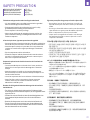 6
6
-
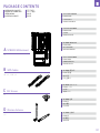 7
7
-
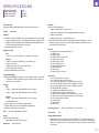 8
8
-
 9
9
-
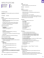 10
10
-
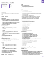 11
11
-
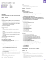 12
12
-
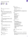 13
13
-
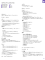 14
14
-
 15
15
-
 16
16
-
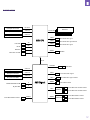 17
17
-
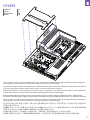 18
18
-
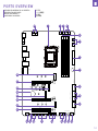 19
19
-
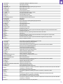 20
20
-
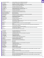 21
21
-
 22
22
-
 23
23
-
 24
24
-
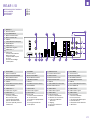 25
25
-
 26
26
-
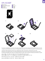 27
27
-
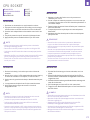 28
28
-
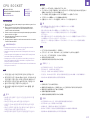 29
29
-
 30
30
-
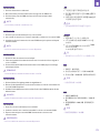 31
31
-
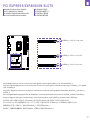 32
32
-
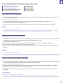 33
33
-
 34
34
-
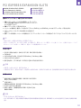 35
35
-
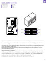 36
36
-
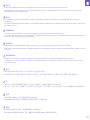 37
37
-
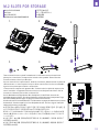 38
38
-
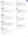 39
39
-
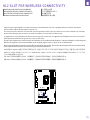 40
40
-
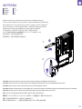 41
41
-
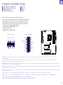 42
42
-
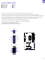 43
43
-
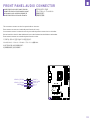 44
44
-
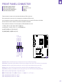 45
45
-
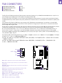 46
46
-
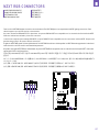 47
47
-
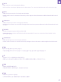 48
48
-
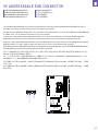 49
49
-
 50
50
-
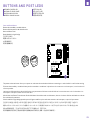 51
51
-
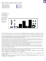 52
52
-
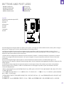 53
53
-
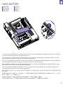 54
54
-
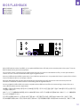 55
55
-
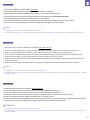 56
56
-
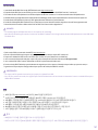 57
57
-
 58
58
-
 59
59
-
 60
60
-
 61
61
-
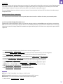 62
62
-
 63
63
-
 64
64
-
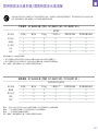 65
65
-
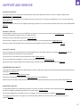 66
66
-
 67
67
-
 68
68


NZXT N7 B650E Manual de usuario
- Categoría
- Placas base
- Tipo
- Manual de usuario
En otros idiomas
- français: NZXT N7 B650E Manuel utilisateur
- português: NZXT N7 B650E Manual do usuário
- 日本語: NZXT N7 B650E ユーザーマニュアル
Documentos relacionados
-
NZXT N7 Z790 Manual de usuario
-
-
NZXT RGB & Fan Controller Manual de usuario
-
-
-
-
-
-
-
Otros documentos
-
Gigabyte GA-MA78LMT-S2 El manual del propietario
-
Digitus DA-71547 Guía de inicio rápido
-
Gigabyte GA-H61M-D2P-B3 El manual del propietario
-
ASROCK B450M PRO4 Manual de usuario
-
ASROCK B450 Pro4 Guía de instalación
-
Shuttle X50V9 53R-X50V93-2001 Guía del usuario
-
-
Lindy USB 3.2 Gen 2x2 Dual M.2 NVMe SSD Enclosure Manual de usuario
-
-