Stoelting VB35/VB60/VB80/VB90/VB120/VB160 Manual de usuario
- Tipo
- Manual de usuario

Operating and maintenance manual
VB 35 - VB 60 - VB 80 - VB90 - VB 120 - VB 160
Translation of the original instructions

2

3
Thank you for choosing this machine. Please read this manual which will allow you to use the machine in
a way that is safe for you and for others. While reading the manual, take the time to familiarise yourself
with the new machine and you will be able to appreciate all of its advantages. You will see that it is user-
IULHQGO\DQGKRZLWFDQHDVLO\FKDQJH\RXUZRUNLQJSURFHVVRSWLPLVLQJLWDQGPDNLQJLWPRUHSUR¿WDEOH
You will understand how the technology used will be of great help to your business TELME S.p.A.
PDFKLQHVDUHWKHSURGXFWRI\HDUVRIH[SHULHQFHPDQXIDFWXULQJPDFKLQHVIRUSURFHVVLQJIRRGVWX௺V
The quality of our machines makes them competitive, reliable, user-friendly, low maintenance, quiet,
safe and ergonomic.
To keep your machine in proper working order, you must carry out the routine maintenance indicated in
the manual. Daily cleaning is fundamental and ensures that machines remain reliable.
To allow us to make sure that the manuals we issue are complete and cover all possible subjects, please
send us any comments based on your direct experience of using the machine.
For operator safety and machine integrity, the machine must only be used for the purpose for which it
ZDVEXLOW7KHUHIRUHDQ\PRGL¿FDWLRQVWRWKHPDFKLQHDQ\SDUWRILWVGHVLJQVDIHW\GHYLFHRUV\VWHPLV
strictly forbidden. Such changes will void any guarantees. The manufacturer declines all responsibility
in the event of substitution of components with non-original parts, improper use, tampering, lack of
maintenance, removal of safety devices and, more generally, any change made to the original design.
2XUTXDOL¿HGWHFKQLFDODVVLVWDQFHVHUYLFHLVDOZD\VDYDLODEOHWR\RXLI\RXKDYHDQ\TXHVWLRQV
Please contact your dealer to solve any technical issues. Do not attempt to solve them yourself, since
this may result in serious danger.
$OORIWKHVWD௺DW672(/7,1*DQGLWVGHDOHUVKRSHWKDW\RXZLOOHQMR\ZRUNLQJZLWKRXUPDFKLQHV
This operating and maintenance manual is part of the machine and must always be kept with it, even
if the machine is sold to a new buyer.

4
CONTENTS
1 GENERAL INFORMATION 6
1.1 General safety instructions 6
1.2 Information about precautions, specific warnings and symbols 6
1.3 Purpose of the manual 7
• 1.3.1 Structure of the manual 7
• 0RGL¿FDWLRQVDQGDGGLWLRQV
• 1.3.3 Requesting help – Technical assistance service 7
1.4 Machine identification data 8
1.5 Intended uses 8
• 1.5.1 Reasonably foreseeable improper use 9
1.6 Information for personnel authorised to use the machine 9
1.7 Packaging, transportation and storage 10
• 1.7.1 Transportation, lifting and handling 10
• 1.7.2 Machine storage 10
2 TECHNICAL SPECIFICATIONS 11
2.1 General description of the machine 11
2.2 Illustration of the machine as a whole and its components 12
2.3 Working and control position 14
2.4 Machine technical data 14
2.5 Noise 16
2.6 Items supplied with the machine 16
3 GENERAL SAFETY REGULATIONS 16
3.1 General instructions 16
3.2 Safety devices present on the machine 18
• 3.2.1 Safety device installed on the cover 18
• 3.2.2 Safety device of the extraction door 18
• 3.2.3 Safety symbols and stickers 19
3.3 Personal Protective Equipment (PPE) 19
• 3.3.1 Clothing 19
• 3.3.2 Gloves (hand protection) 19
• 3.3.3 Hair cover 19
4 INSTALLATION INSTRUCTIONS 20
4.1 General requirements 20
4.2 Ambient conditions 20
4.3 Spaces needed for use of the machine 21
4.4 Installation and assembly sequences of machine components 21
4.5 Electricity supply 22
4.6 Water-cooled machine 23
4.7 Air-cooled machine 24

5
5 MACHINE OPERATION 25
5.1 Controls 25
5.2 Switching on and starting the machine 27
5.3 Programming (All models) 28
• 5.3.1 Adjusting the temperature-based cooling cycle (P1) 29
• 5.3.2 Adjusting the time-based cooling cycle (P2) 29
• 5.3.3 The machine operating time (P3) (only models VB 35, VB 60, VB 80) 30
• 5.3.4 Adjusting the buzzer (P3) (only models VB90, VB120, VB160) 31
• 5.3.5 Gelato retain time (P4) (only models VB90, VB120, VB160) (only with Time-based cycle production) 31
• 5.3.6 The machine operating time (P5) (only models VB 90, VB120, VB160) 31
• 5.3.7 Cylinder Temperature Retain Function (button F) (only models VB90, VB120, VB160) 32
5.4 Temperature-based cycle production 33
• 5.4.1 Modifying the cooling temperature with the temperature-based cycle started 34
5.5 Time-based cycle production 35
• 5.5.1 Modifying the mixing time with the time-based cycle started 36
6 PRE-WASHING 37
7 WASHING 37
7.1 Simple washing 38
• 7.2 Accurate washing and disassembling of the parts 39
• 7.3 Reassembly 42
• 7.4 Sanitization 44
8 ROUTINE MAINTENANCE 46
8.1 Type of checks and interval between them 46
8.2 Maintenance work 46
8.3 Maintenance intervals and time needed 46
8.4 Maintenance sheets 47
8.5 Checks on safety devices 50
• 8.5.1 Checking the safety device installed on the cover 50
9 TROUBLESHOOTING 51
9.1 General alarm indications displayed on the control panel – causes and solutions 52
9.2 Troubleshooting – flowchart 56
10 INACTIVITY 61
10.1 Keeping the machine efficient if it remains inactive 61
11 DECOMMISSIONING THE MACHINE 62
11.1 Description of method of disposal 62
Introduction
Contents

6
1 GENERAL INFORMATION
1.1 General safety instructions
Before using the machine, carefully read all of this manual, which is an integral part of the machine.
Knowing the information and instructions in this manual is essential for users to use the machine correctly and safely.
7KHPDQXIDFWXUHUGHFOLQHVDOOUHVSRQVLELOLW\LQWKHHYHQWRIPRGL¿FDWLRQVWDPSHULQJRUDQ\RSHUDWLRQVFDUULHGRXWLQDZD\
WKDWGRHVQRWFRLQFLGHZLWKZKDWLVVSHFL¿HGLQWKLVPDQXDOVLQFHWKH\PD\SXWWKHKHDOWKDQGVDIHW\RISHUVRQQHODQGRU
REMHFWVDWULVN7KHPDQXIDFWXUHUUHVHUYHVWKHULJKWWRWDNHOHJDODFWLRQDJDLQVWDQ\RQHZKRPRGL¿HVLWVPDFKLQHVZLWKRXW
written permission.
7KHSHUVRQLQFKDUJHRIPDFKLQHXVHDQGRUWKHHPSOR\HUPXVWPDNHVXUHWKDWXVHUVDUHWUDLQHGDQGDZDUHRIDOOLQIRUPDWLRQ
and instructions in the documentation supplied.
Users are only permitted to carry out work on the machine which is within their area of responsibility and for which they
have been trained.
7KHXVHUVKDOOEHKHOGIXOO\UHVSRQVLEOHIRUDQ\PRGL¿FDWLRQVKHPDNHVWRWKHPDFKLQH
2QO\RSHUDWRUVZLWKWKHDSSURSULDWHSURIHVVLRQDOWHFKQLFDOTXDOL¿FDWLRQVPD\FDUU\RXWFKHFNVRUUHSDLUVRQWKHPDFKLQH
Reliable operation and optimised machine performance are only guaranteed by the use of original spare parts. The man-
ufacturer reserves the right to make any changes considered appropriate to the machine described without prior notice.
7KHXVHULVUHVSRQVLEOHIRUDOORSHUDWLRQVQHHGHGWRNHHSWKHPDFKLQHHႈFLHQWGXULQJLWVXVH
,QIRUPDWLRQDERXWSUHFDXWLRQVVSHFL¿FZDUQLQJVDQGV\PEROV
Where necessary, this manual includes information alongside machine operating and maintenance instruc-
tions or procedures.
7KHUHDUHDOVRLQGLFDWLRQVPDUNHGZLWKWKH³&DXWLRQ'DQJHU´V\PEROVVKRZQLQEROGW\SHDQGXSSHUFDVH
letters to make them clearly visible.
7KH³*(1(5,&&$87,21'$1*(5´V\PEROLVXVHGWRLQGLFDWHWKDWIDLOXUHWRFRPSO\ZLWKWKHVDIHW\
regulations described in this manual could result in “Damage to the machine and/or objects and injury
to machine users”.

7
1.3 Purpose of the manual
This manual was drawn up with the aim of providing all machine users, in the most complete and clearest way possible, with
all information necessary for machine installation, use and maintenance, from the time the machine reaches the market until
WKHGD\LWLVGHFRPPLVVLRQHGDQGRUVFUDSSHG
It also lists all procedures useful for dealing with emergencies which may arise during use of the machine as described by
the manufacturer and those which are reasonably foreseeable.
IMPORTANT NOTE: THE MANUAL DOES NOT SUBSTITUTE TECHNICAL TRAINING FOR PERSONNEL
WHO
WILL USE THE MACHINE. IT SHOULD BE CONSIDERED A GUIDE TO THE USE OF MACHINE FUNC-
TIONS.
1.3.1 Structure of the manual
7KHPDQXDOFRQVLVWVRIDVLQJOHGRFXPHQWGUDZQXSLQGHVFULSWLYHODQJXDJHDQGZLWKDOO¿JXUHVQHFHVVDU\IRUFRUUHFWLQWHU-
pretation and implementation of the activities required for machine operation and maintenance.
This manual includes all instructions with which the user must be familiar and information which the user may consult in
order to achieve the aims of the manual.
0RGL¿FDWLRQVDQGDGGLWLRQV
7KLVPDQXDOUHÀHFWVWKHVWDWHRIWKHPDFKLQHDWWKHWLPHLWUHDFKHGWKHPDUNHWDQGLVFRQVLGHUHGDQLQWHJUDOSDUWRIWKH
machine.
$Q\PRGL¿FDWLRQVLPSURYHPHQWVRUDGMXVWPHQWVDSSOLHGWRPDFKLQHVVXEVHTXHQWO\PDUNHWHGGRQRWREOLJHWKH)DFWRU\WR
apply such changes to a machine previously supplied, nor to consider it and the related manual lacking and inadequate.
the Factory reserves the right, should it deem it appropriate and for valid reasons, to update the manuals already on the mar-
NHWVHQGLQJLWVFXVWRPHUVVKHHWVRIWHFKQLFDODQGRURSHUDWLQJXSGDWHVZKLFKPXVWEHFRQVLGHUHGDQGNHSWLQWKHPDQXDO
5HTXHVWLQJKHOS±7HFKQLFDODVVLVWDQFHVHUYLFH
Any request for action by the Technical Assistance Service must be sent by fax or e-mail to the dealer from which the machine
ZDVSXUFKDVHG7KHPDQXIDFWXUHU¶VVDOHVVXSSRUWQHWZRUNFDQEHIRXQGDWKWWSZZZVWRHOWLQJFRP
:KHQUHTXHVWLQJKHOSRUWHFKQLFDODVVLVWDQFHDOZD\VVSHFLI\
1. type of machine, model, product code, serial number and year of construction;
2. faults found;
3. dealer through which the machine was purchased;
4. tax document indicating the date of machine purchase by the user.
Chapter 1
General Information

8
0DFKLQHLGHQWL¿FDWLRQGDWD
7KHGDWDSODWHLVORFDWHGDWWKHWRSRIWKHPDFKLQHUHDUSDQHODQGVKRZVDOORIWKHGDWDQHHGHGIRUPDFKLQHLGHQWL¿FDWLRQ
1. Model – type of machine; 6. Number of phases;
2. Machine serial number; 7. Max. power;
3. Date of production (Year); 8. Max. current drawn;
4. Electric power supply voltage; 9. Type and quantity of refrigerant gas;
5. Electric power supply frequency; 10. The values of high and low pressure.
This data must be indicated in all information documents, for example for every request for technical assistance or when
requesting spare parts.
REMOVAL OF OR TAMPERING WITH THE IDENTIFICATION PLATE IS STRICTLY PROHIBITED.
,QWHQGHGXVHV
7KH9%UDQJHRIPDFKLQHVDUHGHVLJQHGIRU
1. mixing, churning the pasteurized mix or ready-packaged foods, inserted in the machine cylinder, for making gelato,
sorbet and granita.
2. chilling and freezing the ingredients processed, to obtain a creamy gelato, a sorbet or a granita.
This processing takes place in a vertical cylinder using a mixer and retaining paddle supplied with the machine.
7KHPDFKLQHRSHUDWLQJPRGHVIRUPDNLQJJHODWRDQGVRUEHWLQFOXGH³WHPSHUDWXUHEDVHG´RU³WLPHEDVHG´RSHUDWLQJF\FOHV
3OXVXVLQJDVSHFL¿FSURJUDPZLWKDWHPSHUDWXUHEDVHGF\FOHLWLVSRVVLEOHWRPDNHJUDQLWD
THE MACHINE CANNOT BE USED FOR OTHER PURPOSES WITHOUT TELME S.P.A.'S AUTHOR-
ISATION. TELME S.P.A. WILL NOT BE RESPONSIBLE FOR DIRECT OR INDIRECT DAMAGES
DUE TO IMPROPER USE OF THE MACHINE.
1
2 3
4
5
6
7 8
9
10

9
1.5.1 Reasonably foreseeable improper use
%DVHGRQH[SHULHQFHXVLQJWKHPDFKLQHLQDFWXDORSHUDWLQJFRQGLWLRQVZHUHFRPPHQGWKDW\RXIROORZWKHVHLQVWUXFWLRQV
1. Do not insert in the cylinder a quantity of mix that is less than that recommended, as it could lead to ice forming on the
cylinder wall. That would make the machine noisy, cause wear and damage to the mixer scrapers. The suitable quan-
tity of product which can be processed is indicated in sec. 2.4 “Machine technical data" of this manual.
2. Do not insert in the cylinder a quantity of mix that is more than that recommended, as it could prevent correct mix
mixing, and the product can leak out of the cylinder. That would stress the mixer’s motor-driven shaft. The suitable
quantity of product which can be processed is indicated in sec. 2.4 “Machine technical data" of this manual.
3. Do not press the extraction button when the mix or product in the cylinder is liquid, because the high rotating speed of
the mixer (counterclockwise) would make the product come out of the cylinder suddenly. (Consult section 5.1 “Con-
WUROV´LQWKLVPDQXDO
4. Do not press the extraction button at the end of the granita production cycle, because the high rotating speed of the
mixer (counterclockwise) would make the product come out of the cylinder suddenly. Press the MIX button (mixer
clockwise rotation) to make the granita come out of the machine cylinder correctly and safely. (Consult section 5.1
³&RQWUROV´LQWKLVPDQXDO
$WWKHHQGRISURFHVVLQJGRQRWOLIWWKHFRYHUDQGGRQRWUHPRYHWKHPL[HU¿WWHGLQWKHF\OLQGHUZKLOHWKHWHPSHUDWXUH
RIWKHUHPDLQLQJSURGXFWDQGRURIWKHVXUIDFHRIWKHF\OLQGHULVVXFKWKDWLWULVNVFDXVLQJLQMXULHVGXHWRFRQWDFWZLWKRU
proximity to parts of the machine or materials at a very low temperature. Use suitable gloves that protect against low
WHPSHUDWXUHVDQGRUXVHVXLWDEOHSURWHFWLYHFORWKLQJ
,QIRUPDWLRQIRUSHUVRQQHODXWKRULVHGWRXVHWKHPDFKLQH
This manual contains the information needed by authorised personnel to correctly use the machine.
A knowledge of and compliance with the general safety instructions and danger warnings contained in this manual are the
conditions for proceeding, in minimal risk conditions, with installation, putting into service, operating and maintenance of
the machine.
3HUVRQQHODXWKRULVHGWRXVHWKHPDFKLQH
OPERATOR: a person trained for routine operation of the machine, that is to say, loading products to be processed, running
recipes, cleaning and routine maintenance.
QUALIFIED TECHNICIAN: a person whose training and professional education gives him a knowledge of machine service
conditions, and who is able to work on the machine and recognise and avoid any dangerous conditions.
Chapter 1
General Information

10
3DFNDJLQJWUDQVSRUWDWLRQDQGVWRUDJH
The machine is packaged in a wooden or cardboard crate on a pallet having dimensions and features suitable for the type
and weight of the machine. The machine will be delivered packaged, ensuring that it is protected from the elements.
(DFKSDFNDJHLVPDUNHGZLWKWKHIROORZLQJLQIRUPDWLRQ
• Type of machine, model and serial number
• Net and gross weight
• Machine destination
/DEHOVDUHDSSOLHGRQWKHSDFNDJHWRLQGLFDWHWKHIROORZLQJ
• Handle with care
• This way up
• Protect from rain
• Do not stack
• Protect from heat sources
• Fragile
7UDQVSRUWDWLRQOLIWLQJDQGKDQGOLQJ
THE PACKAGE MUST ONLY BE HANDLED BY QUALIFIED TECHNICAL PERSONNEL.
When the machine is delivered, check that during transportation in addition to visible damage no other damage was caused
ZKLFKFRXOGFRPSURPLVHFRUUHFWRSHUDWLRQ2QWKHGHOLYHU\QRWHZULWH³6XEMHFWWRDSSURYDO´WRVKRZWKDWDFFHSWDQFHRIWKH
machine is subject to checks. If any damage is found, within 48 of receiving the machine, report the damage to the haulier
and the manufacturer.
Use a pallet truck or a fork-lift truck, inserting the forks in the holes in the pallet. Use equipment with suitable load-bearing
capacity.
MOVE THE MACHINE USING LIFTING EQUIPMENT WITH A SUITABLE
LOAD-BEARING CAPACITY. DO NOT ATTEMPT TO LIFT THE MACHINE BY
HAND.
0DFKLQHVWRUDJH
The package must not be subjected to impacts, vibrations and other loads.
The machine must be stored indoors, in an area free of aggressive agents, at a temperature not lower than +2 °C, not higher
than +55 °C and with a humidity level of between 10% and 95% (without condensation).

11
2 TECHNICAL SPECIFICATIONS
*HQHUDOGHVFULSWLRQRIWKHPDFKLQH
The VB range of machines covered by this manual are vertical batch freezers for making gelato, sorbet and granita. Pro-
FHVVLQJRIWKHPL[HVRUUHDG\SDFNDJHGIRRGVLVSHUIRUPHGLQDVLQJOHYHUWLFDOF\OLQGHUZKLFKLVHDV\WR¿OOWKHSURGXFWLV
always visible and the ingredients can be added at any time".
The VBUDQJHLQFOXGHVWKHIROORZLQJPRGHOV
- VB 35-109 a
- VB 35-309 a
- VB 60-109 a
- VB 60-309 a
- VB 80-109 a
- VB 90-109 a
- VB 120-109 a
- VB 160-109 a
³9%´PRGHOVFDQPL[FKXUQFKLOODQGIUHH]HWKHLQJUHGLHQWVSURFHVVHGWRREWDLQDFUHDP\JHODWRDVRUEHWRUDJUDQLWD
7KHPDFKLQHRSHUDWLQJPRGHVIRUPDNLQJJHODWRDQGVRUEHWLQFOXGH³WHPSHUDWXUHEDVHG´RU³WLPHEDVHG´RSHUDWLQJF\FOHV
3OXVXVLQJDVSHFL¿FSURJUDPZLWKDWHPSHUDWXUHEDVHGF\FOHLWLVSRVVLEOHWRPDNHJUDQLWD
Chapter 2
7HFKQLFDO6SHFL¿FDWLRQV

12
,OOXVWUDWLRQRIWKHPDFKLQHDVDZKROHDQGLWVFRPSRQHQWV
1 Cover
2 Control panel
3 Cylinder
4 Retaining paddle
5 Mixer
6 Thermal overload protector reset
7 Extraction door lever
8 Extraction door
9 Extraction door chute
10 Basin support
11 Mat
12 Front wheels with brake
13 Outer panels
14 Rear wheels
15 Air cooled condenser (air version machines)
&RQQHFWRUIRULQÀRZRIFRQGHQVDWLRQZDWHUZDWHUYHUVLRQPDFKLQHV
&RQQHFWRUIRURXWÀRZRIFRQGHQVDWLRQZDWHUZDWHUYHUVLRQPDFKLQHV

13
1
2
4
3
5
7
8
9
10
11
13
12
14
16
17
15
6
Chapter 2
7HFKQLFDO6SHFL¿FDWLRQV

14
:RUNLQJDQGFRQWUROSRVLWLRQ
The operator must stand in front of the machine and load the ingredients, programme the recipe, start the processing and
unload the processed product at the end of the recipe.
0DFKLQHWHFKQLFDOGDWD
Model VB 35 VB 60 VB 80
Net weight kg 170 200 250
Coolant gas (type) R448A
For water version (quantity) g 1300 1700 1800
)RUDLUYHUVLRQTXDQWLW\ J
Quantity of product that can be processed (min. - max.) L 3 to 7 4 to 8 7 to 11
Max ambient temperature °C (°F) +30 (+86)
Cylinder capacity L 14 23 28
:$7(5YHUVLRQPDFKLQH(coolant gas pressure) bar 14 14 14
"CONDENSATION" (coolant gas temperature) °C +32 (+89,6)
:$7(5YHUVLRQPDFKLQH(coolant gas pressure) bar 1.0 to 0.6
"EVAPORATION" (coolant gas temperature)
°C (°F) -30 to -36 (-22 to -32,8)
Mains water temperature
°C (°F) +18 to +20 (+64,4 to +68)
Infeed water pressure bar 1 to 7
:DWHUFRQVXPSWLRQ /PLQ 3 to 4 4 to 5 4 to 5
$,5YHUVLRQPDFKLQH(coolant gas pressure) bar 17.2 to 22
"CONDENSATION" (coolant gas temperature)
°C (°F) +40 to +50 (+104 to +122)
$,5YHUVLRQPDFKLQH(coolant gas pressure) bar 1.0 to 0.6
"EVAPORATION" (coolant gas temperature)
°C (°F) -30 to -36 (-22 to -32,8)
Model VB90 VB120 VB160
Net weight kg 290 362 382
Coolant gas (type) R448A
For water version (quantity system 1) g 1400 1600 1800
(quantity system 2) g 1400 1600 1800
Quantity of product processable (min. to max.) L 6 to 12 5 to 18 8 to 24
Max. ambient temperature °C (°F) +30 (+86)
Cylinder capacity L 30 45 53
:$7(5YHUVLRQPDFKLQH(coolant gas pressure) bar 14
"CONDENSATION" (refrigerant gas temperature)
°C (°F) +32 (+89,6)
:$7(5YHUVLRQPDFKLQH(coolant gas pressure) bar 1,0 to 0,6 1,0 to 0,6 1,0 ÷ 0,6
"EVAPORATION" (coolant gas temperature)
°C (°F) -30 to -36 (-22 to -32,8)
Mains water temperature
°C (°F) +18 to +20 (+64,4 to +68)
Infeed water pressure bar 1 to 7
:DWHUFRQVXPSWLRQIRUHDFKV\VWHP /PLQ 3 to 4 4 to 5 4 to 5

15
Model VB 35 VB 60 VB 80 VB90 VB120 VB160
Dimensions L (mm) 490 490 510 510 600 600
P (mm) Water version 700 700 700 700 780 780
3PP$LUYHUVLRQ
H (mm) 1120 1120 1150 1150 1250 1250
H2 (mm) 390 440 440 440 500 500
P2 (mm) 200 200 220 220 220 220
)RUDLUYHUVLRQ(PP
For water version E (mm) 300 300 300 300 300 300
RATED POWER / RATED CURRENT
Power supply voltage (Volts) Frequency (Hz) Phases VB 35 VB 60 VB 80
N:$N:$N:$
$LUYHUVLRQ N:$N:$
RATED POWER / RATED CURRENT
Power supplyvoltage (Volts) Frequency (Hz) Phases VB90 VB120 VB160
N:$N:$N:$
Chapter 2
7HFKQLFDO6SHFL¿FDWLRQV

16
2.5 Noise
The machine is designed and built to conform to the requirements of the regulations in force.
The machine’s exposure limit and action limit values, relative to the level of daily exposure to the peak noise and acoustic
SUHVVXUHDUHUHVSHFWLYHO\OHVVWKDQG%$DQGG%&7HVWGRFXPHQWVDQGFHUWL¿FDWHVIRUWKHLQVWUXPHQWVXVHGIRU
WKHPHDVXUHPHQWVDUH¿OHGDWPDQXIDFWXUHUDQGDUHDYDLODEOHWRPRQLWRULQJDXWKRULWLHV
TEST DOCUMENTS AND CERTIFICATES FOR THE INSTRUMENTS USED FOR THE MEASUREMENTS
ARE FILED AT MANUFACTURER AND ARE AVAILABLE FOR THE MONITORING AUTHORITIES.
,WHPVVXSSOLHGZLWKWKHPDFKLQH
The machine is supplied together with the following items:
1. Operating and maintenance manual.
2. Kit of gaskets and packet of food-safe lubricating grease
3. Spatula for gelato/ice cream
4. Tube brush for cleaning.
5. Basin for washing
6. Machine components: mixer and retaining paddle.
3 GENERAL SAFETY REGULATIONS
3.1 General instructions
THE INSTRUCTIONS LISTED BELOW MUST BE CAREFULLY READ SO THAT USERS ACT AP-
PROPRIATELY ON A DAILY BASIS WHEN OPERATING THE MACHINE AND CARRYING OUT
MAINTENANCE. THIS PREVENTS ANY KIND OF ACCIDENT LINKED TO SITUATIONS INVOLVING
POTENTIAL RISK FOR PEOPLE AND/OR OBJECTS.
)RUWKHVDIHW\RIPDFKLQHXVHUVWKHIROORZLQJVDIHW\LQVWUXFWLRQVPXVWEHFRPSOLHGZLWK
1. Do not attempt to start the machine until you have acquired a suitable understanding of how it operates, by reading
this manual.
2. In case of doubts, even after carefully reading this manual, contact the technical assistance service.
3. Make sure that all personnel involved in using the machine are aware of the safety instructions.
%HIRUHVWDUWLQJWKHPDFKLQHWKHRSHUDWRUPXVWFKHFNIRUDQ\IDXOWVDQGRUGHIHFWVYLVLEOHRQWKHVDIHW\GHYLFHVDQGRQ
the machine. If any faults are found, immediately report them to the manufacturer or to the nearest authorised service
centre.
5. The machine must only be used for the purposes for which it was intended and in accordance with the manufacturer’s
instructions.
6. Every day, check that all safety devices on the machine are operating correctly (see sections 3.2 and 8.5 of this man-
ual).

17
7. Safety devices must not be removed or bypassed for any reason.
8. Any tampering with or modification of the machine not authorised in advance by the manufacturer shall release the
PDQXIDFWXUHUIURPDQ\UHVSRQVLELOLW\IRULQMXU\GDPDJHWRSHRSOHDQGRUREMHFWV
7KHLGHQWLILFDWLRQSODWHDQGVDIHW\V\PEROVVWLFNHUVDSSOLHGWRWKHPDFKLQHPXVWEHNHSWLQSHUIHFWFRQGLWLRQ,IWKH\
are damaged, they must be promptly substituted.
10. Work on electrical connections must only be carried out by qualified technical personnel.
11. The operator must be familiar with the machine controls.
12. The operator must not carry out any operations which are not described in this manual.
13. Only purchase and use original spare parts, which are guaranteed by the manufacturer. Contact the dealer or the
nearest service centre to replace faulty or damaged components.
14. Do not wear clothing, jewellery and accessories which may become tangled in machine moving parts.
15. Keep the area around the machine clear and free of obstructions.
'RQRWSXWILQJHUVDQGRUREMHFWVLQWKHPDFKLQHVORWVRUKROHV
17. Do not use the machine with damp or wet hands.
18. Always wear suitable gloves and a hair cover for hygiene.
19. Pay maximum attention to all caution and danger signs on the machine.
20. The machine must be installed in a location protected from rain and sun.
'RQRWDOORZZDWHUDQGRUOLTXLGVWRSHQHWUDWHWKHPDFKLQH
'RQRWRSHQWKHPDFKLQHSDQHOVVLQFHWKHPDFKLQHFRQWDLQVFRPSRQHQWVSDUWVZKLFKFDQQRWEHPDLQWDLQHGE\WKH
user.
23. Do not lean or sit on the machine while it is operating.
24. Do not apply to the machine other devices which are not part of the kit supplied by the manufacturer.
25. Clean the machine outer panels with soft cloths moistened with detergent for food-safe machines. Do not use water
MHWVDVWKH\PD\GDPDJHFRPSRQHQWVSDUWVLQVLGHWKHPDFKLQH
26. Do not use any kind of solvent, such as spirit, benzene or thinner to clean any of the machine surfaces.
27. Do not operate the machine while under the effects of alcohol, mental health medications or medications in general.
28. This machine must not be used by persons under the age of 18.
,PSURSHUXVHRIWKHPDFKLQHPD\FDXVHKD]DUGVIRURSHUDWRUVDQGRUPD\GDPDJHWKHPDFKLQH
30. If the machine develops any problems not covered in this manual, contact the Technical Assistance Service.
31. Use of the machine is not permitted in places with a potentially explosive atmosphere and in places with ambient
conditions not envisaged in point 4.2 of this manual.
32. The machine is not designed to be used by people with reduced physical, sensory or mental capacity.
Chapter 3
6DIHW\UHJXODWLRQV

18
6DIHW\GHYLFHVSUHVHQWRQWKHPDFKLQH
7KHWHUPVDIHW\GHYLFHUHIHUVWR³DFRPSRQHQWVSHFLDOO\GHVLJQHGE\WKHPDQXIDFWXUHUDQGDOVRVROGVHSDUDWHO\IURPWKH
machine in order to be able to perform safety functions. Therefore, a safety component will be considered a device whose
failure to function compromises the safety of exposed persons.
6DIHW\GHYLFHLQVWDOOHGRQWKHFRYHU
7KHLQVLGHRIWKHPDFKLQHLV¿WWHGZLWKDPDJQHWLFVDIHW\VHQVRU
(A, not visible in the photographs), designed to detect the magnet
%¿WWHGRQWKHFRYHU
!
Incorrect positioning of the magnet activates a machine
alarm, preventing it from starting. The magnet (B) must be
positioned with the arrows (1-2) VERTICAL.
Note: If the cover is opened during an operating cycle (e.g.: to add ingredients), the cycle will be
“PAUSED”, then will continue from where it left off only after the cover has been closed.
THE MAGNETIC SAFETY SENSOR IN THE COVER MUST NOT BE USED AS A MACHINE STOP
CONTROL.
THE MACHINE MUST ONLY BE STOPPED BY PRESSING THE RELATIVE "STOP" ICON, NOT BY
OPENING THE COVER (SEE SECTION 5.1"CONTROLS" IN THIS MANUAL).
6DIHW\GHYLFHRIWKHH[WUDFWLRQGRRU
The machine has an extraction door which allows the processing cylinder to be
sealed. Use the lever (A) to open the plate for extracting the processed foods.
7KHF\OLQGHUH[WUDFWLRQGRRUXVHGWRH[WUDFWWKHSURGXFWLV¿WWHGZLWKD¿[HGJULOOH
%GHVLJQHGWRSUHYHQW¿QJHUVIURPEHLQJLQVHUWHGDFFLGHQWDOO\
DO NOT INSERT TOOLS (E.G.: TUBE BRUSH FOR CLEANING, ETC.) IN THE GRILLE OF THE
EXTRACTION DOOR WHEN THE MACHINE IS OPERATING.
TAMPERING WITH THE SAFETY DEVICE AND USE OF THE MACHINE IF IT IS DAMAGED OR
MALFUNCTIONING ARE STRICTLY PROHIBITED.
THE MANUFACTURER DECLINES ALL RESPONSIBILITY IN THE EVENT OF TAMPERING WITH
SAFETY DEVICES OR OPERATIONS CARRIED OUT IN A WAY THAT DOES NOT COINCIDE WITH
WHAT IS SPECIFIED IN THIS MANUAL, SINCE THEY MAY PUT THE HEALTH AND SAFETY OF
PERSONNEL AND/OR OBJECTS AT RISK.
TAMPERING WITH THE SAFETY DEVICE AND USE OF THE MACHINE IF IT IS DAMAGED OR
MALFUNCTIONING ARE STRICTLY PROHIBITED.
B
1
2
B
A
B

19
6DIHW\V\PEROVDQGVWLFNHUV
On the machine there are symbols/stickers for highlighting: what you must not do, important information and
warnings:
This symbol indicates the presence of an electric shock hazard.
It indicates to the relevant personnel that they risk an electric shock if they do not work in
compliance with safety regulations.
3HUVRQDO3URWHFWLYH(TXLSPHQW33(
7KHHPSOR\HUPXVWLQIRUPSHUVRQQHODERXWWKHIROORZLQJVDIHW\UHODWHGLVVXHV
1 Accident risks.
2 Operator safety equipment.
3 General accident-prevention rules envisaged by the regulations in place in the country for which the machine
is intended.
7KHRSHUDWRUPXVWDOZD\V
1 Pay maximum attention to all caution or danger symbols/stickers on the machine.
2 Not wear clothing, jewellery or accessories which may become tangled in machine parts.
Personal protective equipment to be used by personnel authorised to use the machine:
&ORWKLQJ
Operators must wear clothing made of material resistant to the type of product to be
processed. The clothing must allow perfect movement for the operations that the oper-
ator must perform.
*ORYHVKDQGSURWHFWLRQ
Gloves must be suitable for the machine operating conditions and the operator’s hands.
They must guarantee a secure, rapid grip as well as high performance in resisting the
product to be handled. They must guarantee adequate comfort, absorb sweat and protect
against heat and cold.
+DLUFRYHU
Hair covers must be the correct size and must hold the hair inside. They must be breath-
able to allow for scalp sweating.
PPE MUST CONFORM TO THE SAFETY REQUIREMENTS OF THE REGULATIONS IN FORCE IN
THE COUNTRY WHERE THE MACHINE IS USED.
PP
TH
P
T
Chapter 3
6DIHW\UHJXODWLRQV

20
4 INSTALLATION INSTRUCTIONS
4.1 General requirements
INSTALLATION MUST ONLY BE PERFORMED BY QUALIFIED TECHNICAL PERSONNEL.
Once the package is near to the machine installation location,
cut the straps (A) and remove the cardboard (B) by pushing it
upwards.
Remove the documents and accessories located on the outside
of the machine.
Take care when removing the straps, as they may
accidentally hit the operator when cut.
5HPRYHERWKRIWKHPDFKLQHVLGHSDQHOVE\XQVFUHZLQJWKH¿[-
LQJVFUHZV&WKHQXQVFUHZWKHEROWV'ZKLFK¿[WKHPDFKLQH
frame to the base of the packaging.
/LIWWKHPDFKLQHRႇWKHSDOOHWE\DFWLQJRQWKHORDGEHDULQJSDUWV
(P) of the frame, using lifting equipment suitable for the weight
of the machine. During lifting pay special attention to the power
cable, taking care not to damage it.
DO NOT ATTEMPT TO LIFT
THE MACHINE BY HAND.
After positioning the machine in the selected area, put the side panels back on using the screws and dispose of the pack-
aging materials in accordance with the rules in force in the country where the machine will be used.
$PELHQWFRQGLWLRQV
$PELHQWFRQGLWLRQVUHTXLUHGIRUPDFKLQHRSHUDWLRQ
! Temperature: +2°C to +30°C (35.6°F to 86°F) ! Humidity: 10% - 95% (with no condensation)
THE MACHINE MUST BE POSITIONED IN A LOCATION PROTECTED FROM RAIN AND SUN.
$PELHQWFRQGLWLRQVRWKHUWKDQWKRVHVSHFL¿HGPD\FDXVHVHULRXVGDPDJHWRWKHPDFKLQHDQGLQSDUWLFXODUWRWKHHOHFWULFDO
equipment and the refrigerating system.
OPERATING THE MACHINE IN AMBIENT CONDITIONS THAT DO NOT CONFORM TO THE INDI-
CATIONS IN THIS MANUAL WILL VOID THE GUARANTEE.
USE OF THE MACHINE IN POTENTIALLY EXPLOSIVE ATMOSPHERES IS STRICTLY PROHIBITED.
A
B
D
C
P

21
6SDFHVQHHGHGIRUXVHRIWKHPDFKLQH
The machine must be positioned on a solid, level and even
ÀRRU,WPXVWQRWEHGLUHFWO\H[SRVHGWRVXQOLJKWRUQHDUWR
heat sources.
Keep the machine air inlets clear to allow adequate air cir-
culation around it.
,QVWDOODWLRQDQGDVVHPEO\VHTXHQFHVRIPDFKLQHFRPSRQHQWV
For safety reasons and to avoid damage during transportation, some machine components are removed from it. Therefore,
WKHPDFKLQHXVHUPXVWIROORZWKHVHDVVHPEO\LQVWUXFWLRQVIRUPDFKLQHFRPSRQHQWV
([WUDFWLRQGRRUOHYHU
• Install the opening lever (A) on the extraction door. Place it in the seat
$DQGXVHWKH$OOHQNH\%VXSSOLHGWRWLJKWHQWKH¿[LQJVFUHZ
while holding the lever in the operating position.
([WUDFWLRQGRRUFKXWH
• Install the extraction door chute below the extraction door using the
¿[LQJKROHV&RQWKHIURQWSDQHO
• Position the chute and tighten the 2 clamp screws (D) below it.
TIGHTEN THE CLAMP SCREWS, CHECKING THAT THERE IS NO PLAY IN THE CHUTE.
%DVLQVXSSRUWDQGPDW
• There are two slots (F) in the back of the basin support. Fit them over
the clamp screws (G) partly tightened on the front panel. When the
basin support is in place, tighten the screws.
• Place the mat (H) supplied on top of the basin support.
A
A1
B
C
D
F
G
H
Chapter 4
,QVWDOODWLRQ

22
4.5 Electricity supply
WORK ON ELECTRICAL CONNECTIONS MUST ONLY BE CARRIED OUT BY QUALIFIED TECHNICAL
PERSONNEL.
The machine must be powered at the voltage shown on the data plate at the top of the rear panel. Connect the machine
only to a power supply using a suitable earth connection.
The machine is supplied with a power cable to which DTXDOL¿HGWHFKQLFLDQ must connect a plug suitable for the technical
data (voltage, current) on the data plate.
Connect the machine to a power socket using a suitable earth connection.
THE ELECTRIC SYSTEM THAT WILL POWER THE MACHINE MUST BE DESIGNED IN ACCORDANCE
WITH THE REGULATIONS IN FORCE AND INSTALLED BY QUALIFIED, CERTIFIED TECHNICAL PER-
SONNEL.
THE SOCKET MUST BE CONTROLLED BY A RESIDUAL CURRENT OPERATED CIRCUIT BREAKER,
AND MUST HAVE AN EFFECTIVE EARTH CONNECTION.
THE MANUFACTURER DECLINES ALL RESPONSIBILITY FOR ANY DAMAGE CAUSED BY AN UN-
SUITABLE ELECTRICITY SUPPLY SYSTEM OR EARTHING.
AT THE END OF MACHINE INSTALLATION, QUALIFIED TECHNICAL PERSONNEL MUST CHECK THAT
THE MIXER ROTATES IN THE CORRECT DIRECTION, "CLOCKWISE".
THE USE OF EXTENSION LEADS WHICH HAVE A CROSS-SECTION DIFFERENT TO THAT OF THE
MACHINE POWER CABLE MAY RESULT IN THE FOLLOWING FAULTS:
1. SLOW MOTOR START WITH TRIPPING OF OVERLOAD SWITCHES
2. MOTOR OVERHEATING WITH A DROP IN POWER
3. FAILURE OF MACHINE SWITCH ON - SWITCH OFF DEVICE
THE MANUFACTURER RECOMMENDS INSTALLATION OF THREE-PHASE MAGNE TO-THERMAL
OVERLOAD SWITCHES WHICH ALLOW POWER TO BE CUT OFF TO ALL PHASES EVEN IN THE EVENT
OF AN OVERLOAD ON ONLY ONE OF THEM. OTHER TYPES OF MAGNETO-THERMAL SWITCHES OR
FUSES ONLY CUT THE PHASE WHICH WAS SUBJECT TO OVERLOADING. IF THE VOLTAGE WERE
TO FAIL IN ONE OF THE THREE PHASES, THE MACHINE WOULD NOT STOP OPERATING, BUT THE
MOTORS WOULD QUICKLY SUFFER IRREPARABLE DAMAGE.

23
:DWHUFRROHGPDFKLQH
For machines with a water-cooled condenser, a water supply tube and a water drainage tube
KDYHWREH¿WWHG&RQQHFWDYDOYHRUWDSEHIRUHWKHGHOLYHU\WXEH
The threaded connectors are on the back of the machine, in the lower area. Each connector is
PDUNHGZLWKDODEHOLQGLFDWLQJLWVSXUSRVHDVEHORZ
A. IN - Machine water infeed (pressure between 1 and 7 bar)
B. OUT - Machine water outfeed
For the water connections, use rubberised fabric tubes suitable for a pressure of up to 15 bar.
7RFRQQHFWWKHWXEHVWRWKHPDFKLQH¶VWKUHDGHGFRQQHFWRUVXVHô´¿WWLQJVZLWKJDVNHWVDQG
a suitable tube tightening clip, with clamp screws. Connect a valve or tap before the delivery
WXEHVRDVWRUHJXODWHWKHLQÀRZRIZDWHU
DO NOT INVERT CONNECTION OF THE TUBES AND MAKE SURE THE TUBES ARE NOT PINCHED
OR BENT AT TIGHT ANGLES.
WATER FED IN WHICH IS AT A TEMPERATURE THAT IS TOO HIGH (ABOVE 28°C) WOULD PRE-
VENT CORRECT OPERATION OF THE HEAT EXCHANGER FITTED ON THE MACHINE.
UNSUITABLE TUBES OR CONNECTORS MAY CAUSE LEAKS, WITH CONSEQUENT PROBLEMS
IN THE WORKING ENVIRONMENT. WATER LEAKS MAY SERIOUSLY DAMAGE THE MACHINE.
IF THE MAINS WATER USED TO SUPPLY THE MACHINE IS HARD WATER OR CONTAINS A LOT
OF IMPURITIES, INSTALL A SUITABLE DECALCIFICATION OR FILTERING DEVICE UPSTREAM
OF THE DELIVERY TUBE.
MACHINE WATER INFEED (IN) PRESSURE MUST BE BETWEEN 1 AND 7 BAR. IF NOT THE
MACHINE WILL DEVELOP OPERATING FAULTS.
IF THE MACHINE WATER INFEED (IN) PRESSURE IS ABOVE THE LIMITS ALLOWED, INSTALL
A SUITABLY REGULATED PRESSURE LIMITER UPSTREAM OF THE DELIVERY TUBE. IF NOT
THE MACHINE COULD BE DAMAGED AND STOP OPERATING.
IN TEMPERATURES BELOW 0°C IT IS ESSENTIAL TO EMPTY THE WATER FROM THE MACHINE
COOLING SYSTEM. OTHERWISE IT COULD FREEZE IN IT, CAUSING SERIOUS DAMAGE.
B
A
1
Chapter 4
,QVWDOODWLRQ

24
$LUFRROHGPDFKLQH
Air-cooled machines must be installed with a minimum distance from the rear wall of at least 500 mm to allow free circulation
of condensation air.
Every day, clean the area around the machine to prevent foreign
bodies (for example: build-up of dust, bits of paper, etc.) from
EORFNLQJWKHUHJXODULQÀRZRIDLU0RQWKO\WKRURXJKO\FOHDQWKH
condenser grille, removing any dust residues, bits of paper, etc.,
to allow the machine to operate correctly.
5HPRYHGXVWIURPWKHFRQGHQVHUJULOOHV³GU\´ZLWKDYDFXXPFOHDQHU
and, if necessary, a brush, so that the dust is removed outwards.
DO NOT USE LIQUIDS BECAUSE THEY WOULD FIX THE DUST ON THE CONDENSER.
REMOVE DUST FROM THE CONDENSER GRILLES OUTWARDS TO AVOID COMPROMISING THE
PERFORMANCE OF THE REFRIGERATING SYSTEM.
INADEQUATE MACHINE VENTILATION COULD COMPROMISE CORRECT OPERATION AND ITS
PRODUCTION CAPACITY.

25
5 MACHINE OPERATION
5.1 Controls
7KHFRQWUROSDQHOIXQFWLRQVDUHLOOXVWUDWHGEHORZ
1. ON/OFFEXWWRQ )RUVZLWFKLQJWKHPDFKLQHRQDQGRႇ7KHGLJLWDOGLVSOD\
VKRZVWKHWHPSHUDWXUHRIWKH³FRROLQJ´F\OLQGHUIURQWF\OLQGHU
D3RZHU/(' Power ON light. When lit the LED indicates that the machine is
supplied with electricity.
'LJLWDOGLVSOD\ Displays the machine functions and data set.
3.
$GMXVWPHQWEXWWRQ This button is only active during programming functions.
Pressing it increases the selected value.
%0DLQWHQDQFH$GMXVWPHQWEXWWRQ) Dual function button:
a) increases the value selected in the various programming functions when pressed.
b) The MAINTENANCE button functions only once the other functions have been deactivated. On being pressed,
maintenance of the cylinder is activated at 0°C. For further details see Par. 5.3 – Programming.
4.
$GMXVWPHQWEXWWRQ This button is only active during programming functions. Press
to reduce the selected value.
5.
Buzzer button 7XUQV212))WKHDFRXVWLFVLJQDODWWKHHQGRIWKHKHDWLQJ
cycle. When the buzzer is ON, the warning light (5a) is lit.
6. Economizer button (only models VB90-120-160) The machine is provided with an energy-saving function
(1 refrigerating circuit only). Press this button to enable it (the respective indicator light (6a) turns on).
0L[EXWWRQ 6ZLWFKHV212))FORFNZLVHURWDWLRQRIWKHPL[HULQWKHXSSHU
tank, in manual mode. When mixing is ON the warning light (7a) is lit.
8. “TIME-BASED CYCLE” button %XWWRQIRUVWDUWLQJDPDFKLQH³WLPHEDVHG´RSHUDWLQJF\FOH
:KHQWKHF\FOHLV21WKHZDUQLQJOLJKWDLQWKHEXWWRQLVOLW:KHQWKLVEXWWRQLVSUHVVHGWKHPL[HULQWKH³IURQW´
cylinder and the machine cooling system are switched on automatically for a factory set mixing time. The time-based
RSHUDWLQJF\FOHHQGVZKHQWKHPL[LQJWLPHVHWKDVHODSVHG7KHFRROLQJV\VWHPVZLWFKHVRႇDXWRPDWLFDOO\ZKLOVWWKH
clockwise mixing of the mixer continues to prevent the formation of ice on the sides of the cylinder. Press the button
again to deactivate the cycle and stop the machine.
1a 1
1a 1
2
2
3
3B
4
4
6a
5a
7a
7 8 9a8a
5
9
10
11a 11
6
7a
7 8 9a8a
9
10
11a 11
VB 90
VB 120
VB 160
VB 35
VB 60
VB 80
Chapter 5
8VLQJWKHPDFKLQH

26
9. “TEMPERATURE-BASED CYCLE” button%XWWRQIRUVWDUWLQJDPDFKLQH³WHPSHUDWXUHEDVHG´RSHUDWLQJF\-
FOH:KHQWKHF\FOHLV21WKHZDUQLQJOLJKWDLQWKHEXWWRQLVOLW:KHQWKLVEXWWRQLVSUHVVHGWKHPL[HULQWKH³IURQW´
cylinder and the machine cooling system are switched on automatically. The temperature-based cycle ends when the
SURGXFWLQWKHF\OLQGHUUHDFKHVWKHIDFWRU\VHWFRROLQJWHPSHUDWXUH7KHFRROLQJV\VWHPVZLWFKHVRႇDXWRPDWLFDOO\
whilst the clockwise mixing of the mixer continues to prevent the formation of ice on the sides of the cylinder. Press the
button again to deactivate the cycle and stop the machine.
3URJUDPPLQJEXWWRQ )RUDFFHVVLQJPDFKLQH³FRROLQJ´F\FOHSURJUDPPLQJIXQFWLRQV
VHHVHF³3URJUDPPLQJ´
([WUDFWLRQEXWWRQ 6WDUWVVWRSVWKHFRXQWHUFORFNZLVHURWDWLRQRIWKHPL[HULQVLGHWKH
³IURQW´F\OLQGHUWRDOORZWKHSURGXFWWRFRPHRXWRIWKHH[WUDFWLRQGRRUDWWKHHQGRIWKHFRROLQJF\FOH:KHQH[WUDFWLRQ
is activated the warning light (11a) comes on.
DO NOT PRESS THE EXTRACTION BUTTON WHEN THE MIXTURE OR PRODUCT IN THE CYLIN-
DER IS LIQUID, BECAUSE THE HIGH ROTATION SPEED OF THE MIXER (COUNTERCLOCKWISE)
WOULD MAKE THE PRODUCT COME OUT OF THE CYLINDER SUDDENLY.
DO NOT PRESS THE EXTRACTION BUTTON AT THE END OF THE GRANITA PRODUCTION CY-
CLE, BECAUSE THE HIGH ROTATING SPEED OF THE MIXER (COUNTERCLOCKWISE) WOULD
MAKE THE PRODUCT COME OUT OF THE CYLINDER SUDDENLY. PRESS THE MIX BUTTON
(MIXER CLOCKWISE ROTATION) TO MAKE THE GRANITA COME OUT OF THE MACHINE CYL-
INDER CORRECTLY AND SAFELY.

27
6ZLWFKLQJRQDQGVWDUWLQJWKHPDFKLQH
EVERY DAY, WHEN YOU SWITCH ON THE MACHINE, CHECK THAT THE SAFETY DEVICES ARE
OPERATING CORRECTLY AS DESCRIBED IN DETAIL IN SECTION 8.5 OF THIS MANUAL.
Connect the machine power cable to a socket and check that the power LED
LVOLW3UHVVWKH212))EXWWRQWRSUHSDUHWKHPDFKLQHWRRSHUDWH
and the cylinder temperature is shown on the digital display (2).
3RVVLEOHPDFKLQHRSHUDWLQJPRGHV
1. Production with “time”-based operating cycle, for making gelato and sorbet.
2. Production with “temperature”- based operating cycle, for making gelato and sorbet.
Once the operation mode has been selected, and the pasteurised mixture or the pre-packaged food products have been
placed inside the cylinder, simply press the relative start button to start the production.
Before starting production, remember to run the machine wash phases as described in sections 6-7,
“Pre-washing and Washing”, of this manual.
Before starting the production carry out the following checks:
- Check that the mixer and retaining paddle locking knobs are
fully tightened.
- Check that the extraction door is closed and pour the pasteur-
ised mixture or the pre-packaged food products in the cylinder. The
suitable quantity of product which can be processed is indicated in
sec. 2.4, “Machine technical data" of this manual.
- For water-cooled machines, check that the water inlet tap is open.
- For air-cooled machines, check that the machine is positioned
with the required space from the rear wall and that there are no
IRUHLJQERGLHVREVWUXFWLQJWKHFRQGHQVHUDLUÀRZ
Do not start the machine operating cycle before putting the mix in the cylinder. The mixer must
not operate with no product inside it as it will be damaged.
500 mm
2
2
1
1
Chapter 5
8VLQJWKHPDFKLQH

28
3URJUDPPLQJ$OOPRGHOV
DURING ITS FACTORY INSPECTION, THE MACHINE HAS BEEN PROGRAMMED WITH OPTIMAL
TIME AND TEMPERATURE PARAMETER VALUES FOR THE OPERATION CYCLES.
DO NOT CHANGE PROGRAMMING UNLESS IT IS STRICTLY NECESSARY.
IF PARAMETER VALUES DO NEED TO BE ALTERED, MAKE ANY NECESSARY MACHINE PROGRAM-
MING CHANGES.
ƒ &KHFNWKDWWKHSRZHU/('LVRQDQGSUHVVWKHPDFKLQH21
2))$EXWWRQ
ƒ The machine prepares itself to operate and subsequently the
tank temperature is displayed on the digital display (2).
ƒ .HHSWKH³352*5$00,1*´%EXWWRQSUHVVHGIRUDIHZVHF-
onds to access the programming functions.
ƒ The functions are divided into four clearly separate categories
DQGDUHLGHQWL¿HGE\DÀDVKLQJFRGHWKDWLVGLVSOD\HGLQVH-
quence on the machine digital display.
&RGH )XQFWLRQ
P1 Adjusting the temperature-based cycle
P2 Adjusting the time-based cycle
P3 Machine operating time
P4 Gelato retain time (only models VB90, VB120, VB160)
H-0 Machine operating time (thousands "H-0"expressed in hours)
000 Machine operating time (Hundreds, tens, units "000" expressed in hours)
THE SWITCH BETWEEN FUNCTIONS OCCURS AUTOMATICALLY WITH A TIME INTERVAL OF 5 SEC-
ONDS. TO ACCESS THE FUNCTION TO ADJUST THE OPERATOR MUST WAIT FOR THE DISPLAY TO
SHOW THE CODE ASSOCIATED TO THE DESIRED FUNCTION.
AT THE END OF THE PROGRAMMING CYCLE THE SYSTEM EXITS THE FUNCTIONS AUTOMATICALLY
AND THE CYLINDER TEMPERATURE IS SHOWN ON THE DIGITAL DISPLAY.
B
A
A
1
1
B
2
2

29
C
D
$GMXVWLQJWKHWHPSHUDWXUHEDVHGFRROLQJF\FOH3
ƒ 3UHVVWKH³352*5$00,1*´EXWWRQ%WRDFFHVVSURJUDPPLQJ
IXQFWLRQV7KHGLJLWDOGLVSOD\VKRZVWKHÀDVKLQJFRGH3
ƒ 3UHVVWKH³352*5$00,1*´EXWWRQ%DJDLQ$QXPEHUYDOXHLQ-
dicating the cooling temperature set appears on the display. Press
adjustment buttons (C) and (D) to increase or reduce the cooling
temperature value.
ƒ The cooling temperature can be adjusted within a range between
-12°C and +6°C ( 5°F... 50 °F). The factory set value is -8,8°C (16
°F)
THE COOLING TEMPERATURE MUST BE PROGRAMMED ACCORDING TO THE QUANTITY OF
ANTI-FREEZING INGREDIENTS (FOR EXAMPLE: SUGAR OR ALCOHOL) IN THE MIXTURE TO BE
PROCESSED.
AS A GUIDE, FOR “LEAN” MIXTURES (WITH ONLY A FEW ANTI-FREEZING INGREDIENTS) A COOLING
TEMPERATURE OF -5 to -6 °C (23... 21°F) SHOULD BE SET.
FOR MIXTURES WITH A MEDIUM QUANTITY OF ANTI-FREEZING INGREDIENTS A COOLING TEM-
PERATURE OF -7 to -8 °C (20... 18 °F) SHOULD BE SET.
FOR “RICH” MIXTURES WITH A LARGE QUANTITY OF ANTI-FREEZING INGREDIENTS A COOLING
TEMPERATURE OF -9 to -10 °C (17...14°F) SHOULD BE SET.
$GMXVWLQJWKHWLPHEDVHGFRROLQJF\FOH3
ƒ 7KHQSUHVVWKH³352*5$00,1*´EXWWRQ%7KHGLJLWDOGLVSOD\
VKRZVWKHÀDVKLQJFRGH33UHVVWKH352*5$00,1*EXWWRQ
(B) again. The digital display shows a number value indicating the
mixing time for the product processed in the cylinder. The mixing
time corresponds to the length of the time-based cycle, expressed
in minutes.
ƒ Press adjustment buttons (C) and (D) to increase or reduce the
mixing time value.
ƒ The length of the time-based operating cycle can be adjusted
within a range between 1 and 60 minutes. The factory set value
is 8 minutes.
B
C
D
B
Chapter 5
8VLQJWKHPDFKLQH

30
7KHPDFKLQHRSHUDWLQJWLPH3RQO\PRGHOV9%9%9%
ƒ 3UHVVWKH³352*5$00,1*´EXWWRQ%DJDLQDQGWKH3FRGH
ÀDVKLQJ DSSHDUVRQ WKHGLVSOD\3UHVV WKH³352*5$00,1*´
button again and the machine operating time is displayed, using
WKHWH[W³+´ZKLFKFRUUHVSRQGVWRWKHPDFKLQHRSHUDWLQJWLPHLQ
WKRXVDQGVRIKRXUVIRUH[DPSOHIROORZHGE\WKHQXPEHUV³´
LQGLFDWLQJKXQGUHGVWHQGVDQGXQLWVRIKRXUVRIRSHUDWLRQ
6HHWKHIROORZLQJH[DPSOHV
D
10 hours
The digital display shows H-0 followed by “010
D
250 hours
The digital display shows H-0 followed by “250
E
1250 hours
7KHGLJLWDOGLVSOD\VKRZV+IROORZHGE\³´
F
2250 hours
7KHGLJLWDOGLVSOD\VKRZV+IROORZHGE\³´
B

31
$GMXVWLQJWKHEX]]HU3RQO\PRGHOV9%9%9%
ƒ 7KHQSUHVVWKH³352*5$00,1*´EXWWRQ%7KHGLJLWDOGLVSOD\
VKRZVWKHÀDVKLQJFRGH33UHVVWKH³352*5$00,1*´EXWWRQ
(B) again to view the length of the buzzer sound at the end of the
cooling cycle. The factory set value is 10 seconds.
ƒ Press adjustment buttons (C) and (D) to increase or reduce the
length of the buzzer sound, expressed in seconds.
ƒ The length of the buzzer sound can be adjusted within a range
between 0 and 30 seconds.
ƒ ,IDWLPHRIVHFRQGVLVHQWHUHGWKHEX]]HULVVZLWFKHGRႇ
*HODWRUHWDLQWLPH3RQO\PRGHOV9%9%9%RQO\ZLWK7LPHEDVHGF\FOH
SURGXFWLRQ
ƒ 7KHQSUHVVWKH³352*5$00,1*´EXWWRQ%7KHGLJLWDOGLVSOD\
VKRZVWKHÀDVKLQJFRGH3
ƒ 3UHVVWKH³352*5$00,1*´EXWWRQ%DJDLQZLOODSSHDUUHIULJHU-
ation circuit operating and stopping times, for the retain of the ge-
lato (expressed in seconds), the advised time (and one which has
been pre-set in the factory) for both operating and stopping is 15
VHFRQGV7KHUHJXODWLRQ¿HOGLV´´IRUERWKVHWWLQJV
ƒ Press adjustment buttons (C) and (D) to increase or reduce the
length of the buzzer sound, expressed in seconds.
7KHPDFKLQHRSHUDWLQJWLPH3RQO\PRGHOV9%9%9%
ƒ 3UHVVWKH³352*5$00,1*´EXWWRQ%DQGWKH3FRGHÀDVK-
LQJDSSHDUVRQWKHGLVSOD\3UHVVWKH³352*5$00,1*´EXWWRQ
(B) again and the machine operating time is displayed, using the
WH[W³+´ ZKLFK FRUUHVSRQGVWR WKH PDFKLQHRSHUDWLQJ WLPHLQ
WKRXVDQGVRIKRXUVIRUH[DPSOHIROORZHGE\WKHQXPEHUV³´
LQGLFDWLQJKXQGUHGVWHQGVDQGXQLWVRIKRXUVRIRSHUDWLRQ
ƒ For example (See Sec. 5.3.3).
C
D
B
C
D
B
Chapter 5
8VLQJWKHPDFKLQH

32
&\OLQGHU7HPSHUDWXUH5HWDLQ)XQFWLRQEXWWRQ)RQO\PRGHOV9%9%9%
ƒ %\SUHVVLQJWKH³)´EXWWRQ&DWWKHHQGRIDZRUNLQJF\FOHRQO\
with cold cylinder) the operator activates the CYLINDER TEMPER-
ATURE RETAIN function.
Use of this optionis advised in cases of continuous gelato produc-
tion. Once inserted, the machine keeps cylinder temperature at
0°C, and hence ready for another production cycle.
THE CYLINDER TEMPERATURE RETAIN DOES NOT GO AT ROOM TEMPERATURE INSERTED
WITH RESIDUAL OF REMAINED GELATO/WATER INSIDE OF the CYLINDER, BECAUSE THE
MIXER WOULD COME DAMAGED.
ON ALL THE MODELS
When you press the “PROGRAMMING” button (B) again (or wait for a few seconds), the Display
EULHÀ\VKRZV>@LQGLFDWLQJWKDWVHWXSGDWDKDYHEHHQVWRUHGWKH6(783PRGHWHUPLQDWHVDQG
the machine is ready to be used.
C
B

33
7HPSHUDWXUHEDVHGF\FOHSURGXFWLRQ
ƒ &KHFNWKDWWKHSRZHU/('$LVOLWDQGSUHVVWKHPDFKLQH21
2))EXWWRQ
Note: You can check and if necessary modify the cooling temperature value, depending on the type of
mix and quantities of ingredients that prevent freezing. Follow the instructions in section 5.3.1 of this
manual.
THE COOLING TEMPERATURE MUST BE PROGRAMMED ACCORDING TO THE QUANTITY OF AN-
TI-FREEZE INGREDIENTS (FOR EXAMPLE: SUGAR OR ALCOHOL) IN THE MIXTURE TO BE PRO-
CESSED.
AS A GUIDE, FOR “LEAN” MIXTURES (WITH ONLY A FEW ANTI-FREEZE INGREDIENTS) A COOLING
TEMPERATURE OF -5 ÷ -6 °C (23... 21°F), SHOULD BE SET.
FOR MIXTURES WITH A MEDIUM QUANTITY OF ANTI-FREEZE INGREDIENTS A COOLING TEMPER-
ATURE OF -7 ÷ -8 °C (20... 18 °F), SHOULD BE SET.
FOR “RICH” MIXTURES WITH A LARGE QUANTITY OF ANTI-FREEZE INGREDIENTS A COOLING
TEMPERATURE OF -9 to -10 °C (17...14°F), SHOULD BE SET.
- Before starting the production check that the extraction door is
closed and pour the pasteurised mixture or the pre-packaged
food products in the cylinder.
Note: The suitable quantity of product which can be processed is indicated in sec. 2.4, “Machine technical
data" of this manual.
- Close the cover and start the temperature-based operating cycle
by pressing button (E). The mixer in the cylinder and the machine
cooling system are automatically switched on simultaneously.
The light in the “TEMPERATURE-BASED CYCLE” button (E)
DQGWKDWLQWKH³0,;´EXWWRQ)FRPHRQ
- The cooling temperature can be adjusted within a range between
-12 °C and +6°C
( 5°F... 50 °F). The factory set value is -8,9°C
(16 °F) (temperature suitable for making gelato and sorbet).
A
E
F
Chapter 5
8VLQJWKHPDFKLQH

34
- At the end of processing, that is to say, when the product cool-
ing temperature has been reached, the operator is alerted by a
buzzer. Once the cycle has ended the cooling system switches
R௺DXWRPDWLFDOO\ZKLOVWWKHFORFNZLVHPL[LQJRIWKHPL[HUFRQWLQ-
ues to prevent the formation of ice on the sides of the cylinder.
- ,ILWLVQRWUHPRYHGWKHSURGXFWUHPDLQVLQWKHPDLQWDLQLQJVWDWH
(storage) in the cylinder with a factory set temperature delta of
2°C (35,6 °F). When the temperature of the product increases
inside the cylinder, the cooling system starts automatically to re-
VWRUHWKHWHPSHUDWXUHVHW7KHZDUQLQJOLJKWVLQWKH0,;EXWWRQ
(F) and “TEMPERATURE-BASED CYCLE” button (E) remain lit
to indicate that the cycle is still active.
ONCE THE CYCLE HAS ENDED WE RECOMMEND EXTRACTING THE PRODUCT TO ENSURE THAT
ITS CONSISTENCY IS NOT CHANGED BY TOO MUCH MIXING.
- Position a suitable container on the machine basin support and
open the extraction door.
- ([WUDFWWKHSURGXFWE\SUHVVLQJWKH³(;75$&7,21´EXWWRQ*
When extraction is activated the warning lamp comes on.
- 8VHWKHVSDWXODVXSSOLHGWRKHOSWKHJHODWRÀRZLQWRWKHWXE
- To end the extraction and stop the machine press the “TEM-
PERATURE-BASED CYCLE” button (E). The warning light for
the temperature-based cycle will go out.
0RGLI\LQJWKHFRROLQJWHPSHUDWXUHZLWKWKHWHPSHUDWXUHEDVHGF\FOHVWDUWHG
If, during the processing cycle, you want to modify the cooling temperature, this can be done by accessing the programming
section. Follow the instructions in section 5.3.1 of this manual.
- Press the + Programming/Adjustment button (B) and wait until
the digital display shows code “P1”.
- $IHZVHFRQGVDIWHUWKHFRGH3ÀDVKHVRQWKHGLVSOD\DQX-
merical value indicating the cooling temperature set appears on
the display (e.g.: -7°C / 19 °F).
- Press the adjustment buttons (C) and (D) to set the new cooling
temperature for the product processed.
F
E
G
E
B
C
D

35
7LPHEDVHGF\FOHSURGXFWLRQ
ƒ &KHFNWKDWWKHSRZHU/('$LVOLWDQGSUHVVWKHPDFKLQH21
2))EXWWRQ
Note: You can check and if necessary modify the mixing time value, depending on the quantity and type
of mix and the number of consecutive production runs. Follow the instructions in section 5.3.2 of this
manual.
- Before starting the production check that the extraction door is
closed and pour the pasteurised mixture or the pre-packaged
food products in the cylinder.
Note: The suitable quantity of product which can be pro-
cessed is indicated in sec. 2.4, “Machine technical data" of
this manual.
- Close the cover and start the time-based operating cycle by
pressing button (H). The mixer in the cylinder and the machine
cooling system are automatically switched on simultaneously.
- 7KHOLJKWLQWKH³7,0(%$6('&<&/(´EXWWRQ+DQGWKDWLQWKH
³0,;´EXWWRQ)FRPHRQ
- The length of the time-based operating cycle can be adjusted
within a range between 1 and 30 minutes. The factory set value
is 8 minutes.
- At the end of processing, that is to say, when the mixing time
set has elapsed, the operator is alerted by a buzzer, the letter “t”
appears on the display. Once the cycle has ended the cooling
V\VWHPVZLWFKHVR௺DXWRPDWLFDOO\ZKLOVWWKHFORFNZLVHPL[LQJRI
the mixer continues to prevent the formation of ice on the sides
of the cylinder.
- 7KHZDUQLQJOLJKWVLQWKH0,;EXWWRQ)DQG³7,0(%$6('&<-
CLE” button (H) remain lit to indicate that the cycle is still active.
ONCE THE CYCLE HAS ENDED WE RECOMMEND EXTRACTING THE PRODUCT TO ENSURE THAT
ITS CONSISTENCY IS NOT CHANGED BY TOO MUCH MIXING.
H
F
F
A
H
F
Chapter 5
8VLQJWKHPDFKLQH

36
- Position a suitable container on the machine basin support and
open the extraction door.
- ([WUDFW WKH SURFHVVHG SURGXFW JHODWR E\ SUHVVLQJ WKH ³(;-
75$&7,21´EXWWRQ*
- When extraction is in progress the warning light is lit.
- 7RHQGWKHH[WUDFWLRQDQGVWRSWKHPDFKLQHSUHVVWKH³7,0(
BASED CYCLE” button (H). The warning light for the time-based
cycle will go out.
0RGLI\LQJWKHPL[LQJWLPHZLWKWKHWLPHEDVHGF\FOHVWDUWHG
If, during the processing cycle, you want to modify the mixing time, this can be done by accessing the programming section.
Follow the instructions in section 5.3.2 of this manual.
- Press the + Programming/Adjustment button (B) and wait until
the digital display shows code “P2”.
- $IHZVHFRQGVDIWHUWKHFRGH3ÀDVKHVRQWKHGLVSOD\DQXPHU-
ical value indicating the time set appears on the display.
– Press the adjustment buttons (C) and (D) to set the new mixing time for the product
processed.
G
H
C
D

37
3ਤਸ਼ਠਲਧਨਭਦ
Do not carry out the rinsing having a very cold cylinder.
- Proceed with rinsing to eliminate the residual ice-cream, using 3 gal.(VB 35), 5 GAL.(VB 60),7 gal.(VB 80 and VB
90),10 gal.(VB 120), 11 gal.(VB 160) of warm water(30°C), if you soon will produce other ice-cream;
- Proceed with rinsing to eliminate the residual ice-cream, using 3 gal.(VB 35), 5 GAL.(VB 60),7 gal.(VB 80 and VB
90),10 gal.(VB 120), 11 gal.(VB 160)of warm water (30°C) and, if the production has come to an end, proceed with
simple washing, accurate washing and disassembling of the parts (see 7 WASHING).
:ਠਲਧਨਭਦ
The fats contained in the ice-cream mixtures are ideal for the growth of bacteria. we recommend
to wash and sanitize with the maximum care every part in contact with product, In accordance
with current health regulations.
For a long life of the device we suggest not to use solvents, abrasive
detergents, or rough sponges, in particular on the plastic and rubber
parts. During the washing operations and in particular during the rins-
ing, activate the beating only for the suggested periods. Otherwise you
could damage the machine. DO NOT press the Temperature-based cycle
button (E) or Time-based cycle button (H) during the washing. Otherwise
you would freeze the water and break the parts of the machine. Do not
press the EXTRACTION Pushbutton (G) because all the washing solution
would come out from the top of the machine. Do not carry out the washing
having a very cold cylinder.
E
H
G
Chapters 6 and 7
3UHZDVKLQJ:DVKLQJ

38
6LPSOHZDVKLQJ
ALWAYS WEAR SUITABLE PROTECTIVE GLOVES.
STEP 1
- Prepare a pail with a solution composed by hot water (Maxim
&0D[LP)DQGGHWHUJHQW*2/'(1*/2E\63$57$1
&+(0,&$/UHVSHFWLQJWKHIROORZLQJDPRXQW
- for models VB 35 use 3 gallons of hot water and 1,1/2 oz. of de-
tergent;
- for models VB 60 use 5 gallons of hot water and 2,1/2 oz. of de-
tergent;
- for models VB 80, VB 90 use 7 gallons of hot water and 3,1/2 oz.
of detergent;
- for models VB 120 use 10 gallons of hot water and 5,1/2 oz. of
detergent;
- for models VB 160 use 11 gallons of hot water and 6 oz. of deter-
gent;
STEP 2
- Check that the extraction door is closed, open lid, pour the deter-
gent solution in the cylinder and close the lid again.
STEP 3
3UHVVWKH0,;EXWWRQ)WKLVZLOOFDXVHWKHGHWHUJHQWVROXWLRQWR
be agitated in the cylinder.
STEP 4
PLQXWHVODWHUSUHVVWKH0,;EXWWRQ)DJDLQWRVWRSWKHPL[HU
position the water collection container supplied (V), on the machine
EDVLQVXSSRUW*UDGXDOO\RSHQWKHH[WUDFWLRQGRRUZLWK
WKHOHYHUDQGOHWWKHGLVLQIHFWDQWVROXWLRQÀRZRXW
STEP 5
- Rinse only with hot potable water (Max.50°C)(Max.122°F), repeat-
ing steps 2,3,4 until the rinse water being drawn from the cylinder
is clear.
F
F
V
20
15
18

39
$FFXUDWHZDVKLQJDQGGLVDVVHPEOLQJRIWKHSDUWV
Carry out these operations only with the socket's main Breaker on POSITION “0”.
7KHLQGLFDWRURIWKH,JQLWLRQEXWWRQRQWKHFRQWUROSDQHOPXVWEHWXUQHGRႇ
STEP 1
• Removing the cover
– 3XOOWKH¿[LQJSLQRXWRIWKHEORFNKRUL]RQWDOO\DQGUHPRYH
the cover (2).
• Removing the retaining paddle
– 8QVFUHZWKH¿[LQJNQREDQGUHPRYHWKHUHWDLQLQJSDGGOH
– Take out the safety stop (5) and remove the movable part (6)
of the retaining paddle.
– 5HPRYHWKHJDVNHWIURPWKH¿[LQJNQREXVLQJD
non-metallic pointed tool, taking care not to damage the knob
seat.
RESIDUAL HAZARD: Mixer's blades and scrapers
are sharp along bottom and external side edges. It
is recommended to use suitable protective gloves
and to handle the mixer only by holding the central
hub and not the blades.
• Removing the mixer
– 8QVFUHZWKH¿[LQJNQREJULSWKHPL[HUFRPSRQHQWGULYH
and pull the mixer (9) out vertically.
– 5HPRYHWKHJDVNHWIURPWKH¿[LQJNQREXVLQJD
non-metallic pointed tool, taking care not to damage the knob
seat.
• Removing the mixer scrapers
– Remove the side scrapers (11) using the tool supplied (12).
,QVHUWWKHWRROXQGHUWKHVFUDSHUDQGSULVHRႇE\SXVKLQJ
the tool down until the side scraper can be removed from its
seat.
– Pull the mixer’s lower scraper (13) from its seat.
• Removing the extraction door
– 8QVFUHZFRXQWHUFORFNZLVHWKH¿[LQJNQREVDQGH[WUDFW
the extraction door (15), using a provided allen key (16),
unscrew the tightening screw (17) and remove the lever
5HPRYHWKHÀDWVSULQJGULYHUDQGELJVSULQJ
the conic springdriver (28) and small spring (29).
1
1
2
3
3
5
5
6
7
8
9
10
8
3
13
11
12
12
14
15
16
18
18
17
29
28
26
27
14
Chapters 6 and 7
3UHZDVKLQJ:DVKLQJ

40
• Removing the mat and basin support
- Remove the mat (21) located on top of the basin support (20),
WKHQUHPRYHWKHEDVLQVXSSRUWE\XQGRLQJWKH¿[LQJ
screws (30) underneath it.
• Removing the extraction door chute
- Unscrew the clamp screws (30) under the extraction door
chute (19) and remove it.
- Remove the extraction door chute gasket (19a) by pulling it
out of its seat.
21
20
30
20
30
19
19
19a
19
STEP 2
3UHSDUHDSDLOZLWKDVROXWLRQFRPSRVHGE\JDOJDO9%DQG9%RIURRPWHPSHUDWXUHZDWHUDQGR]
R]9%DQG9%RIGLVLQIHFWLQJ6$1,7PDQXIDFWXUHGE\63$57$1&+(0,&$/DQGFDUU\RXWWKHFOHDQLQJRI
the underlisted parts, using the provided brushes (Z) as illustrated in the images.
WKHPL[HUDQGWKH¿[LQJNQRE
- the side scrapers (11) and the lower scraper (13);
- the cover (2);
- the extraction door (15);
- the extraction door chute (19);
- the basin support (20) and mat (21);
WKHUHWDLQLQJSDGGOHVXSSRUWWKHVDIHW\SHJWKH¿[LQJ
knob (24) and the movable blade (25)
8
9
11
13
2
15
19
20
21
23
22
25
24
Z

41
STEP 3
3UHSDUHDSDLOZLWKDVROXWLRQFRPSRVHGE\JDOJDO9%JDO9%RIZDWHUDQGR]R]9%
oz.VB160)of disinfecting SANI-T-10 manufactured by SPARTAN CHEMICAL and immerse for at least 5 minutes the under-
OLVWHGSDUWV
WKH¿[LQJNQREVDQG
- the extraction door (15);
- the extraction door chute (19);
WKHÀDWVSULQJGULYHZLWKUHODWLYHELJVSULQJ
- the conic springdrive (28) with relative small spring (29);
- the mixer (9);
- the side scrapers (11) and the lower scraper (13);
- the retaining paddle support (22);
- the movable blade (25) and the safety peg (23);
9
24
8
15
19
11
13
22
25
23
26
27
28
29
STEP 4
%HIRUHUHDVVHPEOLQJWKHFRPSRQHQWVDFFXUDWHO\ZDVKWKH¿[HGSDUWVRIWKHGHYLFHDVLOOXVWUDWHGLQWKHGUDZLQJVDQGXQ-
derlisted, using the solution previously prepared (see STEP 2).
- the extraction pipe (Y), the safety grill, the groove and its edges
using the provided brush (Z).
- the upper surface, the lid's rod and the inside of the cylinder;
STEP 5
$SRWDEOHZDWHUULQVHLVQRWQHFHVVDU\XQOHVVVRVSHFL¿HGE\VWDWHRUORFDORUGLQDQFH
Y
Z
Chapters 6 and 7
3UHZDVKLQJ:DVKLQJ

42
22
21
8
10
9
11
20
13
7.3 Reassembly
These operations must be carried out only with the socket's main breaker on "0".
ALWAYS WEAR NEW SUITABLE PROTECTIVE GLOVES.
STEP 1
$IWHUFDUU\LQJRXWWKHZDVKLQJDVSUHYLRXVO\GHVFULEHGUHLQVWDOOWKHPDFKLQHVSDUWVDVIROORZV
• 5H¿WWLQJWKHPL[HUVFUDSHUV
5H¿WWKHVLGHVFUDSHUVE\¿WWLQJWKHPRQWRWKHSLQV
on the mixer.
- Fit the mixer’s lower scraper (13) in its seat.
• 5H¿WWLQJWKHPL[HULQWKHF\OLQGHU
- Fit the mixer (9) on the motor-driven shaft at the centre of the
cylinder.
To avoid vibrations and/or damaging parts, the
mixing impeller drive must be complete with its
bushing (C) before inserting it on the motor shaft
support.
- Slowly turn the mixer component drive so that the pin (21),
which is part of the shaft structure, engages in the slot (22)
made in the mixer component drive.
%HIRUHVFUHZLQJWKH¿[LQJNQRERQWRWKHVKDIWFKHFNWKDW
WKHJDVNHWLVFRUUHFWO\LQVHUWHGLQLWVVHDW,ILWLVEURNHQ
worn or swollen, substitute it. Tighten the mixer knob (8).
C

43
• 5H¿WWLQJWKHUHWDLQLQJSDGGOH
- Fit the movable part (6) on the support of the retaining paddle
and position the safety stop (5).
- Position the retaining paddle (4) in the seat and use the
knob (3) to secure it to the machine work surface.
%HIRUHWLJKWHQLQJWKH¿[LQJNQREFKHFNWKDWWKHJDVNHW
LVFRUUHFWO\LQVHUWHGLQLWVVHDW,ILWLVEURNHQZRUQRUVZROOHQ
substitute it.
• 5H¿WWLQJWKHFRYHU
- Place the cover (2) over the machine cylinder and line up the
holes in the cover with the through hole in the block.
,QVHUWWKH¿[LQJSLQWRVHFXUHWKHFRYHUWRWKHPDFKLQH
&KHFNWKDWWKH¿[LQJSLQLVFRPSOHWHO\LQVHUWHGLQWKHKROHVLQ
the cover and the block.
THE INCORRECT INSTALLATION OR CONTACT FAILURE OF THE MAGNET ON THE COVER ACTI-
VATES A MACHINE ALARM, PREVENTING IT FROM STARTING.
• 5H¿WWLQJWKHH[WUDFWLRQGRRU
¿[WKHOHYHUWRWKHORFNLQJGRRUXQVFUHZLQJWKHWLJKW-
ening screw (17) with a provided allen key (16);
- install the locking door (15) as illustrated in the image, taking
FDUHQRWWRGDPDJHLWQRWWRWRXFKLWVLQWHUQDOVXUIDF;LQ
contact with the extraction pipe (Y);
UHLQVWDOOWKHÀDWVSULQJGULYHUZLWKWKHUHODWLYHELJVSULQJ
DQGWKH¿[LQJNQRE>RQWKHOHIWVLGHWKHFRQLFVSULQJGULYHU
ZLWKWKHUHODWLYHVPDOOVSULQJDQGWKH¿[LQJNQRE
on the right side;
5
6
7
3
3
2
1
1
T
V
V
V
V
V
V
4
18
X
15
17
16
Y
26
27
28
29
14
14
Chapters 6 and 7
3UHZDVKLQJ:DVKLQJ

44
19a
19
30
30
30
20
20
21
30
• 5H¿WWLQJWKHH[WUDFWLRQGRRUFKXWH
,QVHUWWKHH[WUDFWLRQGRRUFKXWHJDVNHWDLQLWVVHDW
- Position the extraction door chute (19) below the extraction
door (15) and secure it by tightening the clamp screws (30)
to the front panel.
TIGHTEN THE FIXING SCREWS, CHECKING THAT THERE IS NO PLAY IN THE CHUTE.
THE INCORRECT INSTALLATION OR CONTACT FAILURE OF THE MAGNET ON THE COVER
ACTIVATES A MACHINE ALARM, PREVENTING IT FROM STARTING.
• 5H¿WWLQJWKHEDVLQVXSSRUWDQGPDW
- Fit the two slots in the basin support (20) over the clamp screws
(30) partly tightened on the front panel. When the basin support
(20) is in place, tighten the screws (30).
- Place the mat (21) on the basin support (20).
15
7.4 Sanitization
$IWHUUH¿WWLQJDOORIWKHFRPSRQHQWVLQWKHPDFKLQHFDUU\RXWWKHVDQLWL]DWLRQZLWKZDWHUVROXWLRQDQGGLVLQIHFWLQJ6$1,7
PDQXIDFWXUHGE\63$57$1&+(0,&$/)ROORZDFFXUDWHO\WKHQH[WVWHSV
STEP 1
- Prepare a pail with a solution composed by room temperature water
DQGGLVLQIHFWLQJ6$1,7UHVSHFWLQJWKHIROORZLQJGRVLQJV
- for models VB 35 use 3 gallons of water and 3/4 oz. of disinfecting
6$1,7
- for models VB 60 use 5 gallons of water and 1,1/4 oz. of disinfect-
LQJ6$1,7
- for models VB 80, VB 90 use 7 gallons of water and 1,3/4 oz. of
GLVLQIHFWLQJ6$1,7
- for models VB 120 use 10 gallons of water and 2,1/2 oz. of disin-
IHFWLQJ6$1,7
- for models VB 160 use 11 gallons of water and 2,3/4 oz. of disin-
IHFWLQJ6$1,7

45
STEP 2
- Check that the extraction door is closed, open lid, pour the solution
in the cylinder and close the lid again.
STEP 3
3UHVVWKH0,;EXWWRQ)WKLVZLOOFDXVHWKHVDQLWL]LQJVROXWLRQWR
be agitated in the cylinder.
STEP 4
PLQXWHVODWHUSUHVVWKH0,;EXWWRQ)DJDLQWRVWRSWKHPL[HU
position the water collection container supplied (V), on the machine
EDVLQVXSSRUW*UDGXDOO\RSHQWKHH[WUDFWLRQGRRUZLWK
WKHOHYHUDQGOHWWKHGLVLQIHFWDQWVROXWLRQÀRZRXW
STEP 5
$SRWDEOHZDWHUULQVHLVQRWQHFHVVDU\XQOHVVVRVSHFL¿HGE\VWDWH
or local ordinance.
After the sanitization, close the lid and do not touch with the hands anymore, nor dry with clothes
or paper all parts in direct contact with food.
Additionally to the operations mentioned in this Chapter, it is recommended to clean machine’s outer
panels and all of its outside parts.
F
F
15
18
V
20
Chapters 6 and 7
3UHZDVKLQJ:DVKLQJ

46
8 ROUTINE MAINTENANCE
ONLY PURCHASE AND USE ORIGINAL SPARE PARTS, WHICH ARE GUARANTEED BY THE
MANUFACTURER. CONTACT THE DEALER OR THE NEAREST SERVICE CENTRE TO REPLACE
FAULTY OR DAMAGED COMPONENTS.
7\SHRIFKHFNVDQGLQWHUYDOEHWZHHQWKHP
Regular checks of the operation of the parts of the machine most subject to stresses and wear can prevent faults and help
to maintain maximum productivity levels, guaranteeing lasting constant operation.
0DLQWHQDQFHZRUN
Maintenance is the set of organised operations which must be carried out on machine parts in a regular, systematic way.
Routine adjustment and maintenance operations carried out by the operator must be performed
with the machine disconnected from the mains power supply.
5RXWLQHPDLQWHQDQFH
FKHFNLQJWKHLQWHJULW\RIZHDUSDUWVVXFKDVVFUDSHUVDQGJDVNHWV
FKHFNLQJWKDWWKHPDFKLQHUHDFKHVDQGPDLQWDLQVWKHSURJUDPPHGWHPSHUDWXUHVZLWKRXWGLIILFXOW\
FKHFNLQJWKDWWKHPDFKLQHGRHVQRWPDNHDQ\XQXVXDOQRLVHV
NHHSLQJRXWHUSDQHOVDQGWKHDUHDQHDUWRDQGXQGHUWKHPDFKLQHFOHDQ'XVWVFUDSVRISDSHURU
RWKHUVPDOOREMHFWVPD\JHWLQWRWKHHTXLSPHQWWKURXJKWKHDLULQOHWVDQGRUEORFNWKHUHJXODULQIORZ
RIDLUWRWKHFRQGHQVHUTXLFNO\FRPSURPLVLQJFRUUHFWPDFKLQHRSHUDWLRQ
0DLQWHQDQFHLQWHUYDOVDQGWLPHQHHGHG
The interval calculated for each piece of maintenance work and the time needed to do the work are approximate and allow
the creation of a maintenance programme.
Correct machine operation can only be guaranteed by methodical, regular maintenance.
7KHWDEOHEHORZVKRZVWKHW\SHRIZRUNLQYROYHGLQURXWLQHPDLQWHQDQFHDQGWKHLQWHUYDOVEHWZHHQMREV
When? Where? How?
Every 500 hours or quarterly Scrapers on the mixer Replace
Every 500 hours or quarterly Mixer guide bushing Replace
(YHU\KRXUVRUTXDUWHUO\ *DVNHWVRQWKH¿[LQJNQREVDQG 5HSODFH
on the extraction door chute
Daily (at machine switch on) Safety devices installed Check that they work
with the procedures described in section 8.5
<HDUO\$OOLQWHUQDOPDFKLQHSDUWV 7KH\PXVWEHFKHFNHGDQGWHVWHGE\DTXDOL¿HG
technician

47
8.4 Maintenance sheets
Substitution of scrapers installed on mixer S01
&+(&.,1*,17(59$/KRXUVRUTXDUWHUO\
$87+25,6('23(5$7252SHUDWRU
7,0(1(('('PLQXWHV
722/7RROVXSSOLHG
Optimum scraping of the cylinder allows good machine performance and product quality.
Substitute the mixer scrapers when they show signs of wear which are obvious when looking at their
VFUDSLQJSUR¿OHVDQGDOVRLQGLFDWHGE\WKHIRUPDWLRQRIVWUHDNVRISURGXFWUHVLGXHRQWKHVXUIDFHRI
the cylinder.
7KHVWDQGDUGPL[HU$KDVVHYHUDOSDUWVPDGHRIIRRGVDIHSODVWLFZKLFKFDQEHVSOLWLQWRWZRW\SHV
- side scrapers (B), snap-on.
- lower scraper (C), slide-on.
– 6XEVWLWXWHDVIROORZV
6LGHVFUDSHUV
• Use the tool supplied (D). Insert it under the scraper to
EHUHSODFHG%DQGSULVHWKHVFUDSHURႇE\SXVKLQJ
the tool down. You can now remove the scraper from
its seat and replace it with a new one (E).
• Position the new scraper (E) on the pin (F) then apply
DVOLJKWSUHVVXUHWR¿WLW
/RZHUVFUDSHU
• 3XOOWKHVOLGHRQORZHUVFUDSHU&RႇWKHPL[HUVWUXF-
WXUHWKHQ¿WDQHZRQH*
B
F
D
G
A
A
E
C
Chapter 8
Maintenance

48
Replacing the gaskets S02
&+(&.,1*,17(59$/KRXUVRUTXDUWHUO\
$87+25,6('23(5$7252SHUDWRU
7,0(1(('('PLQXWHV
722/1RQPHWDOOLFSRLQWHGWRRO
- Regularly check the integrity of the gaskets and substitute them if they are broken, worn or swollen.
- Only use original gaskets, made of food-safe rubber.
- The machine is supplied with a full set of spare gaskets.
DO NOT PUT GASKETS IN THE INDUSTRIAL DISHWASHER, AS THE HIGH TEMPERATURES
COULD DEFORM THEM, MAKING THEM UNUSABLE.
FOR CORRECT GASKET CLEANING, USE A DISPOSABLE
CLOTH AND A DETERGENT FOR ITEMS AND MACHINES
USED FOR FOOD PREPARATION.
)L[LQJNQREJDVNHW
• 5HPRYHWKHZRUQJDVNHW$IURPWKH¿[LQJNQRE
(B) using a non-metallic pointed tool, taking care
not to scratch the knob seat.
• 5HPRYHDOOSURGXFWUHVLGXHVIURPWKHVHDWDQG¿W
the new gasket (C) without lubricating it.
([WUDFWLRQGRRUFKXWHJDVNHW
• Remove the worn gasket (D) from the extraction
door chute (E) by pulling it from the metal seat.
• Replace it with a new one (G)
A
B
C
C
E
D
F

49
Replacing the mixer guide bushing S03
&+(&.,1*,17(59$/KRXUVRUTXDUWHUO\
$87+25,6('23(5$7252SHUDWRU
7,0(1(('('PLQXWHV
722/
- Periodically check that the mixer guide bushing is intact and replace it if damaged or worn.
- Only use original spare parts.
Replace the bushing for the mixer component drive when there are signs of wear.
0L[HUJXLGHEXVKLQJ
• Remove the bushing to be replaced (A) from the mixer com-
ponent drive (B).
• Insert the new bushing (C) into the mixer component drive (B).
TO AVOID VIBRATIONS AND/OR DAMAGING
PARTS, THE MIXER COMPONENT DRIVE
MUST BE COMPLETE WITH ITS BUSHING
BEFORE INSERTING IT ON THE MOTOR
SHAFT SUPPORT.
A
B
C
B
C
Chapter 8
Maintenance

50
&KHFNVRQVDIHW\GHYLFHV
6DIHW\GHYLFHV
&+(&.,1*,17(59$/'$,/<$70$&+,1(6:,7&+21
$87+25,6('23(5$7252SHUDWRU
7,0(1(('('PLQXWHV
722/
DO NOT USE THE MACHINE IF ONE OR MORE SAFETY DEVICES MALFUNCTION OR ARE
DAMAGED!
&KHFNLQJWKHVDIHW\GHYLFHLQVWDOOHGRQWKHFRYHU
Checking procedure:
Phase 1
With the machine empty remove the mixer from the cyl-
inder, close the cover and start the machine by pressing
WKH³RQRႇ´EXWWRQ7KHQSUHVVWKH³0,;´EXWWRQ$
and check that the motor-driven shaft starts up.
Phase 2
Open the cover. If the safety device is operating correctly,
the shaft will stop moving and the digital display will show
DQDODUPPHVVDJH³ƑƑƑ´
Phase 3
Close the cover again and press the MIX button (A) to
stop the motor-driven shaft. Open the cover again and
install the mixer in the cylinder, so that the machine is
ready for use.
A
A

51
9 TROUBLESHOOTING
Most faults and problems during machine operation are promptly automatically indicated by the machine.
ALARMS STOP THE MACHINE, WITH AN EMERGENCY STOP MESSAGE DISPLAYED ON THE CONTROL
PANEL. TO RESTART THE MACHINE, YOU MUST ELIMINATE THE CAUSE OF THE EMERGENCY.
People involved in troubleshooting:
- Operator: SHUVRQWUDLQHGLQWKHRUGLQDU\RSHUDWLRQRIWKHPDFKLQHZKRSHUIRUPVLQLWLDOIDXOW¿QGLQJDQGLISRVVLEOH
by following the instructions in Chapter 8 (Routine maintenance), removes the causes of the fault and restores correct
machine operation.
-
Technical assistance service:TXDOL¿HGWHFKQLFLDQFDOOHGWRZRUNRQWKHPDFKLQHDIWHUDUHTXHVWIRUKHOSDV
VSHFL¿HGLQVHFRIWKLVPDQXDO
Chapter 9
7URXEOHVKRRWLQJ
!

52
*HQHUDODODUPLQGLFDWLRQVGLVSOD\HGRQWKHFRQWUROSDQHO±FDXVHVDQGVROXWLRQV
This section shows the machine alarms, which can be viewed on the digital display, together with possible causes and solutions.
FAULT/
PROBLEM
INSTRUCTIONS
FOR THE
OPERA
TOR
POSSIBLE CAUSES SOLUTIONS
! General alarm warning
“
ƑƑƑ
”:
Ɣ The cover on top of the cylinder
is not closed correctly or tends to
open. The product lifts the cover
because of an excessive quantity
or an excessive increase in volume.
Ɣ 7KH PDJQHW DQGRUWKH PDJQHWLF
sensor in the cover are damaged
DQGRUIDXOW\
Ɣ Pressure increase in the machine
refrigeration system. The refrigera-
tion system safety pressure switch
tripped because the maximum pres-
sure allowed was exceeded.
Ƈ Use lower quantities of product. The suitable quantity of
product which can be processed is indicated in sec. 2.4
“Machine technical data".
Ƈ Contact the Technical Assistance Service which will cor-
UHFWO\UH¿WRUVXEVWLWXWHWKHGRRUPDJQHWRUPDJQHWLF
contact.
$)RUZDWHUFRROHGPDFKLQHV
Ƈ &KHFNWKDWWKHZDWHUWDSLVRSHQDQGZDWHUÀRZVLQFRU-
rectly, as indicated in sec. 2.4 “Machine technical data”.
&KHFNWKDWWKHPDLQVZDWHUÀRZUDWHWHPSHUDWXUHDQG
pressure conform to the indications in sec. 2.4 “Machine
technical data”. Check that there are no narrowings in
the water in/out tubes. Remove any narrowing found.
%)RUDLUFRROHGPDFKLQHV
Ƈ Check for obstructions in front of the air condenser
JULOOHV ,I WKHUH DUH REVWUXFWLRQV SUHVHQW WKH\ PXVW
be removed. Check that the machine is positioned at
the correct distance from the walls, as indicated in the
PDQXDO,ILWLVQRWUHSRVLWLRQLWLQFRPSOLDQFHZLWKWKH
distances indicated in sec. 4.3 “Spaces needed for use
of the machine".
To reset the thermal protections press
the button located on the front of the
machine.
If the problem cannot be solved, contact the Technical
Assistance Service.

53
FAULT/
PROBLEM
INSTRUCTIONS
FOR THE
OPERA
TOR
POSSIBLE CAUSES SOLUTIONS
! General alarm warning
“
ƑƑƑ
”:
Ɣ A fuse designed to protect the aux-
iliary electrical system has blown.
Ɣ Current overload in the compressor
electrical circuit.
The electric pro-
tection device for the refrigerating
system compressor tripped.
Ɣ No voltage in a phase of the power
circuit. In these conditions the com-
pressor generates an electric over-
load on the other phases, tripping its
electric protection device.
Ɣ Mechanical overloading of the mixer
motor. The electric protection device
for the machine motor tripped.
Ƈ Contact the Technical Assistance Service which will
identify and eliminate the cause of the overload and will
substitute the blown fuse with another having the same
VSHFL¿FDWLRQVDQGOHYHORISURWHFWLRQ
Ƈ 6ZLWFK
R௺WKHPDFKLQHZDLWDIHZPLQXWHVWKHQVZLWFK
LWRQDJDLQ,IWKHIDXOWSHUVLVWVRULVUHSHDWHGFRQWDFW
the Technical Assistance Service.
Note: In some cases you may need to wait for up
to 30 minutes for the thermal protection
devices to cool down.
Ƈ 6ZLWFK R௺WKH PDFKLQHDQGFRQWDFWWKH7HFKQLFDO$V-
sistance Service.
THE OTHER PHASES COULD BE LIVE. THE
MACHINE MOTORS WILL BE DAMAGED IF
THEY OPERATE WITH ONE OF THE PHAS-
ES NOT POWERED.
Ƈ Check that the product in the cylinder is not excessively
solid as to cause mechanical stress to the mixer motor
.
6ZLWFKR௺WKHPDFKLQHZDLWDIHZPLQXWHVWKHQVZLWFK
LWRQDJDLQ,IWKHIDXOWSHUVLVWVRULVUHSHDWHGFRQWDFW
the Technical Assistance Service.
Note: In some cases you may need to wait for up
to 30 minutes for the thermal protection
devices to cool down.
To reset the thermal protections press
the button located on the front of the
machine.
f the problem cannot be solved, contact the Technical
Assistance Service.
Chapter 9
7URXEOHVKRRWLQJ
!

54
FAULT/
PROBLEM
INSTRUCTIONS
FOR THE
OPERA
TOR
POSSIBLE CAUSES SOLUTIONS
! Alarm warning
“P--“
Ɣ The cylinder temperature probe
signals a temperature higher than
the safety limits. Faulty tempera-
ture probe (interrupted or out of
WROHUDQFH DQGRU UHODWHGZLULQJ
damaged.
Ƈ Contact the Technical Assistance Service.
! Alarm warning
“PE“
Ɣ The cylinder temperature probe
signals a temperature lower than
the safety limits. Faulty tempera-
ture probe (interrupted or out of
WROHUDQFH DQGRU UHODWHGZLULQJ
damaged.
Ɣ The control circuits do not allow
disconnection of power for the
compressor (which keeps operat-
ing). The related control contactor
is probably jammed.
Ɣ There is little product in the cylinder
with the cooling phase active (ice
forming on the walls of the cylinder).
Ƈ Contact the Technical Assistance Service.
Ƈ Contact the Technical Assistance Service.
Ƈ 6ZLWFK R௺ WKH PDFKLQH ZDLW XQWLO QRUPDO RSHUDWLQJ
conditions are restored and add the quantity of product
which can be processed, indicated in sec. 2.4 “Machine
technical data".

55
FAULT/
PROBLEM
INSTRUCTIONS
FOR THE
OPERA
TOR
POSSIBLE CAUSES SOLUTIONS
! UNSUAL NOISINESS.
Ɣ A layer of ice has developed be-
WZHHQ WKH PL[HUDQGWKH F\OLQGHU
the mixture is not idoneous, or is
QRWVXႈFLHQW
Ɣ Check that the side scrapers are
not worn.
Ɣ 7KH PL[HUDQGRU WKH F\OLQGHUDUH
damaged or excessively worn.
Ɣ 7KHPL[HUDQGRUWKHF\OLQGHUKDYH
gone through a sudden temperature
change, and stress mechanically.
Ƈ The suitable quantity of product which can be processed
is indicated in sec. 2.4, “Machine technical data" of this
manual.
Ƈ ,IWKH\DSSHDUZRUQUHSODFHWKHP
Ƈ Contact the Technical Assistance Service.
Ƈ 6ZLWFKR௺WKHPDFKLQHDQGZDLWDIHZPLQXWHV
Chapter 9
7URXEOHVKRRWLQJ
!

56
7URXEOHVKRRWLQJ±ÀRZFKDUW
,QDEQRUPDOFRQGLWLRQVWKHPDFKLQHPD\PDOIXQFWLRQDVVSHFL¿HGEHORZ
MACHINE DOES NOT OPERATE OR OPERATION IS INTERRUPTED
THE MAIN SWITCH IS IN THE ON POSITION (1), THE POWER
WARNING LIGHT DOES NOT SWITCH ON.
The plug is not inserted in the
socket correctly.
,QVHUWLWFRUUHFWO\
YES
The socket is faulty.
+DYHLWVXEVWLWXWHGE\DTXDOL¿HG
technician.
NO
YES
No electric power in the network or
in the socket.
Check that the disconnecting switches,
all-pole (phase & neutral) isolating switch-
es and residual current operated circuit
breakers (cut-outs) on the electrical sys-
tem, upstream of the socket, are closed.
,IQRWEHIRUHFORVLQJWKHPPDNHVXUHWKDW
no one is carrying out electrical repairs.
NO
YES
A fuse designed to protect the
auxiliary electrical system has
blown.
,GHQWLI\DQGHOLPLQDWHWKHFDXVHRIWKH
overload and substitute the blown fuse
ZLWKDQRWKHUKDYLQJWKHVDPHVSHFL¿FD-
tions and level of protection.
Contact the technical assistance service.
YES
NO
NO
The power cable is damaged.
&XWR௺WKHHOHFWULFLW\VXSSO\WRWKHVRFNHW
by opening the disconnecting switch up-
stream of it, then disconnect the plug and
contact the Technical assistance services.
YES
DO NOT TOUCH DAMAGED ELECTRIC CA-
BLES BEFORE CUTTING OFF THE ELECTRIC-
ITY SUPPLY!
Contact the technical assistance
service
NO

57
MACHINE REPEATEDLY TRIPS THE
ELECTRIC OVERLOAD SWITCHES OR BLOWS THE MAINS FUSES.
The capacity of the electrical
V\VWHPLVQRWVXႈFLHQWWRSRZHU
the machine.
Contact the Technical assistance
service.
YES
7KHHOHFWULFDOVSHFL¿FDWLRQVRIWKH
overload switches or fuses are not
suitable.
NO
YES
Internal machine fault.
NO
Contact the Technical assistance
service.
YES
Contact the Technical assistance
service.
UNUSUAL NOISE
During the cooling phase, a layer
of ice formed between the mixer
DQGWKHF\OLQGHUGXHWRDQLQVXႈ-
cient quantity of product.
,QVHUWDVXLWDEOHTXDQWLW\RISURGXFWLQ
the cylinder, as indicated in sec. 2.4
“Machine technical data".
YES
The mixer scrapers could be
damaged or excessively worn.
NO
YES
7KHPL[HUDQGRUWKHF\OLQGHUDUH
damaged or excessively worn.
NO
&KHFNWKDWWKHVFUDSLQJSUR¿OHVDUHQRW
damaged, and also that the side scrap-
ers do not show obvious signs of wear.
,IWKH\DUHZRUQVXEVWLWXWHWKHP
YES
Contact the Technical assistance ser-
vice.
Chapter 9
7URXEOHVKRRWLQJ
!

58
7KHPL[HUDQGRUWKHF\OLQGHU
have been subjected to a jump in
temperature, which caused me-
chanical strain between the parts.
NO
YES
Stop the machine and wait a few min-
utes until normal operating conditions
are restored.
NO
UNUSUAL NOISE
Contact the technical assistance
service
7KH¿[LQJNQREIRUWKHPRYDEOHSDG-
dle (if present) has worked loose.
Check the condition of the gasket (sub-
stitute it if necessary) and tighten the
knob again.
YES
COOLING IS INSUFFICIENT OR SWITCHES OFF IN A FAULTY WAY
AIR-cooled machine
There are obstructions in front of
the air condenser grilles, or the
distance is less than required in
VHF³0DFKLQHWHFKQLFDOGDWD´
Restore the minimum distance required.
YES
The temperature in the working
environment is too high and there
LVLQVXႈFLHQWFRQGHQVDWLRQ
NO
YES
The air condenser is blocked.
NO
Restore the operating temperature, as in-
dicated in the manual in sec. 2.4 “Machine
technical data”.
YES
Ask the Technical assistance service
for cleaning.
NO

59
COOLING IS INSUFFICIENT OR SWITCHES OFF IN A FAULTY WAY
AIR-cooled machine
The air condenser fan is faulty.
YES
Fault in the refrigerating system or
control electronics
NO
YES
Contact the Technical assistance
service.
Contact the Technical assistance
service.
NO
Contact the technical assistance
service
NO
COOLING IS INSUFFICIENT OR SWITCHES OFF IN A FAULTY WAY
WATER-cooled machine
The condenser water tap(s) are
partly or completely closed.
Open the tap(s).
YES
There are narrowings in the water
connecting pipes.
NO
YES
7KHÀRZRIFRQGHQVHUZDWHULVLQ-
WHUUXSWHGRULQVXႈFLHQW
NO
5HPRYHDQ\ÀDWWHQLQJDQGDYRLGWLJKW
bends in the water connecting pipes.
YES
Check and restore correct water con-
sumption, as indicated in the manual in
sec. 2.4 “Machine technical data”.
Chapter 9
7URXEOHVKRRWLQJ
!

60
COOLING IS INSUFFICIENT OR SWITCHES OFF IN A FAULTY WAY
WATER-cooled machine
The water pressure switch valve
needs adjusting again, or it is faulty.
YES
The temperature of the water fed in
is higher than that indicated in the
manual in sec. 2.4 “Machine tech-
QLFDOGDWD´
NO
YES
Contact the Technical assistance
service.
NO
The compressor overheated due to
DODFNRIRULQVXႈFLHQWYHQWLODWLRQ
NO
Contact the Technical assistance
service.
Clean the outside of the ventilation
openings on the machine side panels
using soft cloths moistened with deter-
gent for food-safe machines.
To reset the thermal protections
press the button.
,IWKHSUREOHPFDQQRWEHVROYHGFRQWDFW
the Technical assistance service.
YES
Fault in the refrigerating system or
control electronics
NO
YES
Contact the Technical assistance
service.
Contact the Technical assistance
service.
NO

61
10 INACTIVITY
.HHSLQJWKHPDFKLQHHFLHQWLILWUHPDLQVLQDFWLYH
,IWKHPDFKLQHZLOOQRWEHXVHGIRUDOHQJWK\SHULRGIROORZWKHVHLQVWUXFWLRQV
- Sanitise the machine as described in chapters 6/7.
6ZLWFKRႇWKHPDFKLQHXVLQJWKH,2212))EXWWRQSRZHUGRZQDWWKHPDLQVPDVWHUVZLWFKDQGWDNHWKH
plug out of the socket.
,IWKHPDFKLQHWKDWZLOOEHLQDFWLYHKDVDZDWHUFRROHGFRQGHQVHUFORVHWKH:DWHU,QWDSDQGGLVFKDUJHWKHZDWHUSUHV-
sure in the delivery tube by unscrewing the end connector. Remove both the delivery tube and the drainage tube and
empty the water from them. Before using again after a long period of inactivity, check the connector gaskets for damage,
substituting them if necessary.
BEFORE STORING A MACHINE THAT HAS A WATER-COOLED CONDENSER IN ENVIRONMENTS
WITH TEMPERATURES BELOW 0°C, COMPLETELY EMPTY THE WATER FROM THE MACHINE
COOLING SYSTEM, AS IT COULD FREEZE INSIDE IT, CAUSING VERY SERIOUS DAMAGE.
,IDPDFKLQHZLWKDQDLUFRROHGFRQGHQVHUKDVEHHQLQDFWLYHEHIRUHVZLWFKLQJLWRQUHPRYHGXVWIURPWKHFRQGHQVHU
grilles “dry” with a vacuum cleaner and, if necessary, a brush, so that the dust is removed outwards.
DO NOT USE LIQUIDS BECAUSE THEY WOULD FIX THE DUST ON THE CONDENSER.
REMOVE DUST FROM THE CONDENSER GRILLES OUTWARDS TO AVOID COMPROMISING
THE PERFORMANCE OF THE REFRIGERATING SYSTEM.
Chapters 10-11
,QDFWLYLW\'HFRPPLVVLRQLQJ
!

62
11 DECOMMISSIONING THE MACHINE
'HVFULSWLRQRIPHWKRGRIGLVSRVDO
The lifetime of the machine estimated by the manufacturer is 20,000 hours (10 years) of operation under normal operating
conditions, described in this operating manual. At the end of its lifetime the machine must be disposed of in accordance with
the regulations in force in the country where it was used, concerning the disposal of waste electrical and electronic equipment.
WHEN DISPOSING OF THE MACHINE ALWAYS COMPLY WITH THE REGULATIONS IN FORCE IN THE
COUNTRY WHERE IT WAS USED.

63
1RWHV
Chapters 10-11
,QDFWLYLW\'HFRPPLVVLRQLQJ
!

TELME S.p.A.
Via S. Pertini, 10 - 26845 Codogno (LO)
Tel.: +39.0377.466.650 - Fax: +39.0377.466.690
e-mail: [email protected] - www.telme.it
Edition 01-2021

Manuel d'utilisation et entretien
VB 35 - VB 60 - VB 80 - VB90 - VB 120 - VB 160
Traduction de la notice originale

2

3
Nous vous félicitons pour l'excellent choix que vous venez de faire et tenons à vous en remercier. Nous
vous invitons à lire ce manuel qui vous permettra d'utiliser la machine en préservant la sécurité de tous.
Cette lecture vous permettra de vous familiariser avec votre nouvelle machine et d'en apprécier tous les
avantages en termes de production. Vous constaterez sa facilité d'utilisation et apprendrez comment
changer de procédé de travail facilement, en l'optimisant et en le rentabilisant.
9RXVDSSUpFLHUH]ODWHFKQRORJLHDSSOLTXpHTXLYRXVDLGHUDJUDQGHPHQWGDQVYRWUHDFWLYLWp(QH௺HWOHV
machines fabriquées par TELME S.p.A. sont l'aboutissement d'années d'expérience dans la réalisation
de machines pour la transformation de produits alimentaires. La qualité de nos machines en font des
pTXLSHPHQWVFRPSpWLWLIV¿DEOHVVLPSOHVjXWLOLVHUQHGHPDQGDQWTXHSHXGHQWUHWLHQVLOHQFLHX[VUV
et ergonomiques.
3RXU FRQVHUYHU OHXU WRWDOH HFDFLWp GDQV OH WHPSV LO HVW LQGLVSHQVDEOH GH௺HFWXHU OHV RSpUDWLRQV
d'entretien ordinaire indiquées dans le manuel. Le nettoyage quotidien est une opération fondamentale
HWQpFHVVDLUHSRXUTXHOHVPDFKLQHVUHVWHQW¿DEOHV
$¿QGpWDEOLUGHVPDQXHOVGHSOXVHQSOXVFRPSOHWVHWH[KDXVWLIVOHIDEULFDQWIDLWDSSHODX[XWLOLVDWHXUV
qui pourront adresser leurs observations dérivant de leur propre expérience.
Pour la sécurité des opérateurs et l'intégrité de la machine, l'usage prévu doit être rigoureusement
respecté ; de même, aucun composant de conception, dispositif ou système de protection ne pourra être
PRGL¿pVRXVSHLQHGDQQXODWLRQGHWRXWHJDUDQWLH/HIDEULFDQWGpFOLQHWRXWHUHVSRQVDELOLWpHQFDVGH
remplacement d'éléments par des modèles non originaux, d'usage impropre, d'altérations intentionnelles,
GHPDQTXHGHQWUHWLHQGHUHWUDLWGHGLVSRVLWLIVGHVpFXULWpHWSOXVJpQpUDOHPHQWGHWRXWHPRGL¿FDWLRQ
apportée à la conception d'origine.
1RWUHVHUYLFH$VVLVWDQFHTXDOL¿pUHVWHjYRWUHGLVSRVLWLRQSRXUWRXWHGHPDQGHjFDUDFWqUHWHFKQLTXH
Adressez-vous à votre revendeur sans tenter de résoudre vous-même d'éventuels problèmes techniques
D¿QGHQHSDVYRXVH[SRVHUjGHJUDYHVGDQJHUV
Tout le personnel de STOELTING et de ses revendeurs vous souhaite un bon travail !
Ce manuel d'utilisation et entretien forme partie intégrante de la machine et doit donc toujours
l'accompagner, y compris en cas de vente.

4
INDEX DES SUJETS TRAITÉS
1 INFORMATIONS GÉNÉRALES 6
1.1 Mises en garde générales de sécurité 6
1.2 Informations sur les précautions, avertissements spécifiques et symboles 6
1.3 Objet du manuel 7
• 1.3.1 Structure du manuel 7
• 1.3.2 0RGL¿FDWLRQVHWFRPSOpPHQWV
1.4 Données signalétiques de la machine 8
1.5 Intended uses 8
• 1.5.1 Usages incorrects raisonnablement prévisibles 9
1.6 Informations pour le personnel chargé d'utiliser la machine 9
1.7 Emballage, transport et stockage 10
• 1.7.1 Transport, levage et manutention 10
• 1.7.2 Stockage de la machine 10
2 CARACTÉRISTIQUES TECHNIQUES 11
2.1 Description générale de la machine 11
2.2 Illustration de l'ensemble et des composants de la machine 12
2.3 Position de travail et de commande 14
2.4 Caractéristiques techniques de la machine 14
2.5 Émission de bruit 16
2.6 Accessoires fournis avec la machine 16
3 RÈGLES GÉNÉRALES DE SÉCURITÉ 16
3.1 Spécifications générales 16
3.2 Dispositifs de sécurité de la machine 18
• 3.2.1 Dispositif de sécurité installé sur le couvercle 18
• 3.2.2 Dispositif de sécurité de la bouche d'extraction 18
• 3.2.3 Symboles et autocollants de sécurité 19
3.3 Équipements de protection individuelle (E.P.I.) 19
• 3.3.1 Tenues de travail 19
• 3.3.2 Gants (protection des mains) 19
• 3.3.3 Charlotte 19
4 INSTRUCTIONS D'INSTALLATION 20
4.1 Exigences générales 20
4.2 Conditions d'environnement 20
4.3 Espaces nécessaires pour l'utilisation de la machine 21
4.4 Installation et séquences de montage des composants de la machine 21
4.5 Alimentation électrique 22
4.6 Machine à refroidissement à eau 23
4.7 Machine à refroidissement à air 24

5
5 FONCTIONNEMENT DE LA MACHINE 25
5.1 Commandes de fonctionnement 25
5.2 Mise sous tension et démarrage de la machine 27
5.3 Programmation (Tous les modèles) 28
• 5.3.1 Réglage du cycle à température (P1) 29
• 5.3.2 Réglage du cycle à temps (P2) 29
• 5.3.3 Temps de fonctionnement de la machine (P3) (seulement modèles VB 35, VB 60, VB 80) 30
• 5.3.4 Réglage de la sonnerie (buzzer) (seulement modèles VB90, VB120, VB160) 31
• 5.3.5 Programmation entretien de la Crème Glacée (avec production CYCLE A TEMPS)
(seulement modèles VB90, VB120, VB160) 31
• 5.3.6 Temps de fonctionnement de la machine (P5) (seulement mod. VB 90, VB120, VB160) 31
• 5.3.7 Fonction entretien temperature du cylindre (touche F) (seulement modèles VB90, VB120, VB160) 32
5.4 Production par cycle à température 33
• 5.4.1 0RGL¿FDWLRQGHODWHPSpUDWXUHGHUHIURLGLVVHPHQWDYHFF\FOHjWHPSpUDWXUHGpPDUUp
5.5 Production par cycle à temps 35
• 5.5.1 0RGL¿FDWLRQGXWHPSVGHWXUELQDJHDYHFF\FOHjWHPSVGpPDUUp
6 PRÉ-LAVAGE 37
7 LAVAGE 37
7.1 Lavage simple 38
• 7.2 Lavage et démontage des composants 39
• 7.3 Remontage 42
• 7.4 Désinfection 44
8 INTERVENTIONS D'ENTRETIEN ORDINAIRE 46
8.1 Nature et fréquence des vérifications 46
8.2 Interventions d'entretien 46
8.3 Fréquence et temps d'entretien 46
8.4 Fiches d'entretien 47
8.5 Vérification des dispositifs de sécurité 50
• 8.5.1 9pUL¿FDWLRQGXGLVSRVLWLIGHVpFXULWpLQVWDOOpVXUOHFRXYHUFOH
9
IDENTIFICATION ET RÉSOLUTION DES PANNES ET ANOMALIES 51
9.1 Signalements d'alarmes générales affichés sur le panneau de commande - causes et solutions 52
9.2 Résolution des pannes et anomalies - diagrammes de flux 56
10 INACTIVITÉ 61
10.1 Maintien de l'efficacité de la machine en cas d'inactivité 61
11 MISE HORS SERVICE DE LA MACHINE 62
11.1 Description des modalités d'élimination 62
Introduction
Table des matières

6
1 INFORMATIONS GÉNÉRALES
1.1 Mises en garde générales de sécurité
Avant d'utiliser la machine, nous vous invitons à lire avec attention et intégralement ce manuel qui en forme partie intégrante.
/DFRQQDLVVDQFHGHVLQIRUPDWLRQVHWGHVVSpFL¿FDWLRQV¿JXUDQWGDQVFHPDQXHOHVWHVVHQWLHOOHSRXUXQXVDJHFRUUHFWHW
sans danger de la machine de la part de l'utilisateur.
/HIDEULFDQWGpFOLQHWRXWHUHVSRQVDELOLWpHQFDVGHPRGL¿FDWLRQVDOWpUDWLRQVLQWHQWLRQQHOOHVRXRSpUDWLRQVHႇHFWXpHVGHIDoRQ
non conforme aux indications de manuel, pouvant atteindre à la sécurité et à la santé de personnes et/ou endommager des
ELHQV/HIDEULFDQWVHUpVHUYHOHGURLWGHSRXUVXLYUHHQMXVWLFHWRXWHSHUVRQQHDSSRUWDQWGHVPRGL¿FDWLRQVVDQVDXWRULVDWLRQ
écrite, aux machines de sa production.
Le responsable de l'utilisation de la machine et l'employeur doivent s'assurer que les utilisateurs sont formés et ont connais-
VDQFHGHWRXWHVOHVLQIRUPDWLRQVHWGHVVSpFL¿FDWLRQV¿JXUDQWGDQVODGRFXPHQWDWLRQIRXUQLH
Les interventions de l'utilisateur sur la machine ne sont autorisées que si elles relèvent de ses compétences et sont à la
hauteur de son niveau de formation.
/XWLOLVDWHXUHVWHQWLqUHPHQWUHVSRQVDEOHGHVPRGL¿FDWLRQVTXLODXUDDSSRUWpHVjODPDFKLQH
Seuls les opérateurs possédant les compétences techniques professionnelles adéquates peuvent intervenir sur la machine
SRXUGpYHQWXHOVFRQWU{OHVRXSRXUUpSDUDWLRQV/D¿DELOLWpGXIRQFWLRQQHPHQWHWORSWLPLVDWLRQGHVSHUIRUPDQFHVGHODPD-
chine ne sont garanties qu'avec l'utilisation de pièces de rechange originales. Le fabricant se réserve le droit d'apporter les
pYHQWXHOOHVPRGL¿FDWLRQVTXLOMXJHUDRSSRUWXQHVjODPDFKLQHGpFULWHVDQVDXFXQSUpDYLV
7RXWHVOHVRSpUDWLRQVQpFHVVDLUHVSRXUFRQVHUYHUOHႈFDFLWpGHODPDFKLQHDXFRXUVGHVRQXWLOLVDWLRQVRQWjODFKDUJHGH
l'utilisateur.
,QIRUPDWLRQVVXUOHVSUpFDXWLRQVDYHUWLVVHPHQWVVSpFL¿TXHVHWV\PEROHV
Ce manuel contient des informations qui viennent compléter des instructions ou procédures d'utilisation
et d'entretien de la machine.
Vous y trouverez également des signalements indiqués par les symboles de « Attention/Danger », en
caractères gras et majuscules pour les mettre en évidence.
/HV\PEROH©$77(17,21'$1*(5*e1e5,48(ªVLJQL¿HTXHOHQRQUHVSHFWGHVUqJOHVGHVpFXULWp
décrites dans ce manuel peut occasionner des « Dommages à la machine et/ou aux biens et des ac-
cidents pour le personnel chargé de son utilisation ».

7
1.3 2EMHWGXPDQXHO
Ce manuel a été établi dans le but de fournir à tous les utilisateurs de la machine, le plus exhaustivement et clairement
possible, toutes les informations nécessaires à l'installation, à l'utilisation et à l'entretien, de sa mise sur le marché jusqu'à
sa mise hors service et/ou élimination.
Toutes les procédures utiles en cas de situations d'urgence pouvant survenir lors des modes d'utilisation indiqués par le
fabricant et des modes raisonnablement prévisibles sont également indiquées.
REMARQUE IMPORTANTE : LE MANUEL NE REMPLACE EN AUCUN CAS LA FORMATION ET LA PRÉ-
P
ARATION TECHNIQUE DU PERSONNEL CHARGÉ D'UTILISER LA MACHINE. IL DOIT ÊTRE CONSIDÉRÉ
COMME UN GUIDE DANS L'EXÉCUTION DE SES FONCTIONS.
1.3.1 Structure du manuel
/HPDQXHOVHFRPSRVHGXQVHXOGRFXPHQWUpGLJpGDQVXQVW\OHGHVFULSWLIHWVDFFRPSDJQHHQDQQH[HVGHWRXWHVOHV¿JXUHV
nécessaires pour une interprétation correcte et un bon déroulement des opérations de conduction et d'entretien de la machine.
/HWH[WHFRQWLHQWWRXWHVOHVVSpFL¿FDWLRQVTXHOHOHFWHXUGRLWFRQQDvWUHHWSHXWDYRLUjFRQVXOWHUSRXUDWWHLQGUHOHVREMHFWLIV
¿[pVSDUFHPDQXHO
1.3.2 0RGL¿FDWLRQVHWFRPSOpPHQWV
&HPDQXHOUHÀqWHOpWDWGHODWHFKQLTXHDXPRPHQWGHODPLVHVXUOHPDUFKpGHODPDFKLQHGRQWLOIRUPHSDUWLHLQWpJUDQWH
7RXWHPRGL¿FDWLRQDPpOLRUDWLRQDGDSWDWLRQDSSRUWpHDX[PDFKLQHVFRPPHUFLDOLVpHVSDUODVXLWHQREOLJHQWSDV/HIDEULFDQWj
intervenir sur les machines fournies précédemment ni à considérer ces machines et leurs manuels incomplets et inadéquats.
Le fabricant a toutefois la faculté, si elle le juge opportun et pour quelque raison que ce soit, de mettre à jour les manuels
préalablement mis sur le marché en adressant à ses clients des feuillets de mise à jour à caractère technique et/ou opéra-
tionnel qui doivent être pris en compte et conservés dans le manuel.
'HPDQGHGLQWHUYHQWLRQ6HUYLFHGDVVLVWDQFHWHFKQLTXH
Toute demande d'intervention du Service d'Assistance Technique clients doit être adressée par fax ou par e-mail au reven-
deur auquel la machine a été achetée. Le réseau de vente/assistance du fabricant peut être consulté sur le site internent
www.stoeltingfoodservice.com
La demande d'intervention ou d'assistance technique devra indiquer :
1. type de machine, modèle, matricule, numéro de série et année de fabrication ;
2. anomalies/pannes constatées ;
3. revendeur ayant vendu la machine ;
GRFXPHQW¿VFDODWWHVWDQWGHODGDWHGDFKDWGHODPDFKLQHSDUOXWLOLVDWHXU
1.3.4 Commande de pièces de rechange
Pour toute demande de pièces de rechange, nous vous prions de contacter votre revendeur habituel ou de consulter la liste
jMRXUGHVFHQWUHVGDVVLVWDQFHDJUppVVXUOHVLWHRႈFLHOGHOHIDEULFDQWZZZVWRHOWLQJIRRGVHUYLFHFRP
Chapitre 1
Informations générales

8
1.4 'RQQpHVVLJQDOpWLTXHVGHODPDFKLQH
La plaque se trouve dans la partie supérieure du panneau arrière de la machine et en indique toutes les informations
GLGHQWL¿FDWLRQ
1. Modèle - type de machine ; 6. Nombre de phases ;
2. Numéro de série de la machine ; 7. Puissance maximale ;
3. Date de fabrication (Année) ; 8. Absorption max. de courant ;
4. Alimentation électrique ; 9. Type et quantité de gaz frigorigène ;
5. Fréquence d'alimentation électrique ; 10. Les valeurs de haute et basse pression.
Ces informations doivent être reportées sur chaque document d'information, par exemple pour toute demande d'assistance
technique ou pour la demande de pièces de rechange.
IL EST STRICTEMENT INTERDIT DE RETIRER OU D'ALTÉRER LA PLAQUE SIGNALÉTIQUE.
1.5 Intended uses
/HVPDFKLQHVGHODFDWpJRULH9%RQWpWpFRQoXHVSRXU
1. mélanger, turbiner le mix pasteurisé ou les produits alimentaires préemballés introduits dans le cylindre de la ma-
chine, pour la préparation de glaces, sorbets et granités.
UHIURLGLUUDSLGHPHQWHWFRQJHOHUOHVLQJUpGLHQWVWUDQVIRUPpVD¿QGREWHQLUXQHJODFHRQFWXHXVHXQVRUEHWRXXQJUD-
nité.
&HVWUDQVIRUPDWLRQVVHႇHFWXHQWGDQVXQF\OLQGUHYHUWLFDOjODLGHGXQPpODQJHXUHWGXQHSDOHWWHGHSRXVVpHIRXUQLVDYHF
la machine.
Les modes de fonctionnement de la machine pour la production de glaces et de sorbets consistent en des cycles de fonc-
WLRQQHPHQWj©WHPSpUDWXUHªRXHQGHVF\FOHVGHIRQFWLRQQHPHQWj©WHPSVª8QSURJUDPPHVSpFL¿TXHDYHFF\FOHGH
fonctionnement à température, permet de plus de réaliser des granités.
LA MACHINE NE PEUT PAS ÊTRE UTILISÉE À D'AUTRES FINS SANS L'AUTORISATION DE
LE FABRICANT QUI NE POURRA ÊTRE TENUE RESPONSABLE DE DOMMAGES DIRECTS OU
INDIRECTS DUS À UN USAGE IMPROPRE DE LA MACHINE.
1
2 3
4
5
6
7 8
9
10

9
1.5.1 8VDJHVLQFRUUHFWVUDLVRQQDEOHPHQWSUpYLVLEOHV
À partir de l'expérience acquise à ce jour de l'utilisation de la machine en conditions de fonctionnement, il est recommandé
de suivre les indications ci-après :
1. Ne pas introduire dans le cylindre une quantité de mix inférieure à la quantité recommandée, ce qui pourrait provo-
quer la formation de glace sur la paroi du cylindre, s'accompagnant d'un bruit anomal de la machine, avec usure et
détérioration des racleurs du mélangeur. La quantité adéquate de produit à traiter est indiquée au paragraphe 2.4 «
Caractéristiques techniques de la machine » de ce manuel.
2. Ne pas introduire dans le cylindre une quantité de mix supérieure à la quantité recommandée, ce qui pourrait em-
SrFKHUGREWHQLUXQERQWXUELQDJHGXPL[VDFFRPSDJQDQWGXQGpERUGHPHQWGHSURGXLWGXF\OLQGUHHWGXQHႇRUW
excessif de l'arbre motorisé du mélangeur. La quantité adéquate de produit à traiter est indiquée au paragraphe 2.4 «
Caractéristiques techniques de la machine » de ce manuel.
3. Ne pas appuyer sur la touche d'extraction lorsque le mix ou le produit à l'intérieur du cylindre est liquide, car la haute
vitesse de rotation du mélangeur (en sens antihoraire) provoquerait un brusque débordement de produit du cylindre.
(Consulter le paragraphe 5.1 « Commandes de fonctionnement » de ce manuel).
1HSDVDSSX\HUVXUODWRXFKHGH[WUDFWLRQHQ¿QGHF\FOHGHSURGXFWLRQGHJUDQLWpFDUODKDXWHYLWHVVHGHURWDWLRQGX
mélangeur (en sens antihoraire) provoquerait un brusque débordement de produit du cylindre. Appuyer sur la touche
de brassage (rotation du mélangeur en sens horaire) pour une évacuation correcte et en sécurité du granité du cy-
lindre de la machine. (Consulter le paragraphe 5.1 « Commandes de fonctionnement » de ce manuel).
(Q¿QGHWUDQVIRUPDWLRQQHSDVVRXOHYHUOHFRXYHUFOHQLHQOHYHUOHPpODQJHXULQVWDOOpjOLQWpULHXUGXF\OLQGUHWDQW
que la température du produit restant et/ou de la surface du cylindre présente un risque de lésions par contact ou par
proximité de parties de la machine ou de matériaux à température très basse. Revêtir des gants appropriés pour se
protéger des basses températures et/ou des vêtements de protection.
1.6 Informations pour le personnel chargé d'utiliser la machine
Ce manuel contient les informations nécessaires pour le personnel chargé de l'utilisation de la machine.
/DFRQQDLVVDQFHHWOHUHVSHFWGHVPLVHVHQJDUGHJpQpUDOHVGHVpFXULWpHWGHVDYHUWLVVHPHQWVGHGDQJHU¿JXUDQWGDQVFH
manuel sont indispensables à l'exécution en condition de risque minimum de l'installation, de la mise en service, du fonc-
tionnement et de l'entretien de la machine.
/HSHUVRQQHOFKDUJpGXWLOLVHUODPDFKLQHSHXWDYRLUOHVSUR¿OVFLDSUqV
OPÉRATEUR : personne formée pour la conduction courante de la machine, à savoir le chargement des produits à trans-
former, l'exécution des recettes, les opérations de nettoyage et d'entretien ordinaire.
TECHNICIEN QUALIFIÉSHUVRQQHTXLSDUVDIRUPDWLRQRXVHVFRPSpWHQFHVSURIHVVLRQQHOOHVFRQQDvWOHVFRQGLWLRQV
GH[HUFLFHGHODPDFKLQHHWHVWFDSDEOHGLQWHUYHQLUVXUFHWWHGHUQLqUHGLGHQWL¿HUHWGpYLWHUWRXWHFRQGLWLRQGHGDQJHU
Chapitre 1
Informations générales

10
1.7 (PEDOODJHWUDQVSRUWHWVWRFNDJH
La machine est emballée dans une caisse en bois ou en carton sur palette de dimensions et caractéristiques adaptées au
type et au poids de la machine. La machine sera livrée emballée en lui garantissant une protection contre l'agression des
agents extérieurs.
Chaque colis présente un marquage indiquant :
• Type de machine, modèle et numéro de série
• Poids net et brut
• Destination de la machine
L'emballage porte des étiquettes indiquant :
• Manipuler avec soin
• Ne pas retourner
• Protéger de la pluie
• Ne pas superposer
• Protéger des sources de chaleur
• Non résistant aux chocs
1.7.1 Transport, levage et manutention
LA MANUTENTION DE LA MACHINE EMBALLÉE DOIT ÊTRE EFFECTUÉE EXCLUSIVEMENT
PAR UN PERSONNEL TECHNIQUE QUALIFIÉ
¬ODOLYUDLVRQGHODPDFKLQHYpUL¿HUTXHSHQGDQWOHWUDQVSRUWDXGHOjGHGRPPDJHVYLVLEOHVGDXWUHVGRPPDJHVVXVFHS-
tibles de compromettre le bon fonctionnement n'ont pas été occasionnés. Indiquer sur le bordereau de livraison la mention
©5pVHUYHGDFFHSWDWLRQªVDXIYpUL¿FDWLRQGHODPDFKLQH(QFDVGHFRQVWDWDWLRQGHGRPPDJHVLOVGRLYHQWrWUHVLJQDOpV
dans les 48 heures suivant la livraison au transporteur et au fabricant.
Transporter la machine sur un transpalette ou un chariot élévateur en introduisant les fourches dans les logements prévus
de la palette. Utiliser un moyen de portée adéquate.
MANIPULER LA MACHINE À L'AIDE D'UN MOYEN DE LEVAGE DE PORTÉE
ADÉQUATE. NE PAS TENTER DE SOULEVER LA MACHINE MANUELLEMENT.
6WRFNDJHGHODPDFKLQH
L'emballage ne doit pas être soumis à des chocs, vibrations et supporter d'autres charges.
Le lieu de stockage de la machine doit être un local fermé, non agressif, à température non inférieure à 2°C (35,6 °F), non
supérieure à 55°C (131 °F), avec un taux d'humidité de 10 % à 95 % (sans condensation).

11
2 CARACTÉRISTIQUES TECHNIQUES
2.1 Description générale de la machine
Les machines de la catégorie VB faisant l'objet de ce manuel sont des turbines verticales pour la production de glaces,
VRUEHWVHWJUDQLWpV/HVWUDQVIRUPDWLRQVGHVPL[SDVWHXULVpVRXGHVSURGXLWVDOLPHQWDLUHVSUpHPEDOOpVVHႇHFWXHQWGDQV
un unique cylindre vertical qui permet : « un remplissage facile, une visibilité constante du produit et l'ajout d'ingrédients à
tout moment ».
La catégorie VB se compose des modèles suivants :
- VB 35-109 a
- VB 35-309 a
- VB 60-109 a
- VB 60-309 a
- VB 80-109 a
- VB 90-109 a
- VB 120-109 a
- VB 160-109 a
/HVPRGqOHV9%PpODQJHQWWXUELQHQWUHIURLGLVVHQWUDSLGHPHQWHWFRQJqOHQWOHVLQJUpGLHQWVWUDQVIRUPpVD¿QGREWHQLUXQH
glace onctueuse, un sorbet ou un granité.
Les modes de fonctionnement de la machine pour la production de glaces et de sorbets consistent en des cycles de fonc-
tionnement à « température » ou en des cycles de fonctionnement à « temps ».
8QSURJUDPPHVSpFL¿TXHDYHFF\FOHGHIRQFWLRQQHPHQWjWHPSpUDWXUHSHUPHWGHSOXVGHUpDOLVHUGHVJUDQLWpV
Chapitre 2
Caractéristiques techniques

12
2.2 ,OOXVWUDWLRQGHOHQVHPEOHHWGHVFRPSRVDQWVGHODPDFKLQH
1 Couvercle
2 Panneau de commande
3 Cylindre
4 Palette de poussée
5 Mélangeur
6 Réinitialisation du protecteur de surcharge thermique
7 Levier du volet d'extraction
8 Volet d'extraction
9 Goulotte de la bouche d'extraction
10 Tablette
11 Tapis
12 Roues avant avec frein
13 Revêtement extérieur
14 Roues arrière
15 Condensateur à air (version machine à air)
16 Raccord d'entrée de l'eau de condensation (version machine à eau)
17 Raccord de sortie de l'eau de condensation (version machine à eau)

13
1
2
4
3
5
7
8
9
10
11
13
12
14
16
17
15
6
Chapitre 2
Caractéristiques techniques

14
2.3 Position de travail et de commande
The operator must stand in front of the machine and load the ingredients, programme the recipe, start the processing and
unload the processed product at the end of the recipe.
2.4 &DUDFWpULVWLTXHVWHFKQLTXHVGHODPDFKLQH
Modèle VB 35 VB 60 VB 80
Poids net kg 170 200 250
Gaz réfrigérant (type) R448A
Pour version à eau (quantité) g 1300 1700 1800
Pour version à air (quantité) g 1650 3000 /
Quantité de produit traitable (min.÷max.) L 3 to 7 4 to 8 7 to 11
Température ambiante max. °C (°F) +30 (+86)
Capacité de cylindre L 14 23 28
Machine version à EAU :(pression gaz réfrigérant) bar 14 14 14
« CONDENSATION » (température gaz réfrig.) °C +32 (+89,6)
Machine version à EAU :(pression gaz réfrigérant) bar 1.0 to 0.6
« ÉVAPORATION » (température gaz réfrig.)
°C (°F) -30 to -36 (-22 to -32,8)
Température de l'eau du réseau
°C (°F) +18 to +20 (+64,4 to +68)
Pression de l'eau en entrée bar 1 to 7
Consommation eau L /min. 3 to 4 4 to 5 4 to 5
Machine version à AIR : (pression gaz réfrigérant) bar 17.2 to 22
« CONDENSATION » (température gaz réfrig.)
°C (°F) +40 to +50 (+104 to +122)
Machine version à AIR : (pression gaz réfrigérant) bar 1.0 to 0.6
« ÉVAPORATION »(température gaz réfrigér.)
°C (°F) -30 to -36 (-22 to -32,8)
Modèle VB90 VB120 VB160
Poids net kg 290 362 382
Gaz réfrigérant (type) R448A
Pour version à eau (quantité équipement 1) g 1400 1600 1800
(quantité équipement 2) g 1400 1600 1800
Quantité de produit traitable (min.÷max.) L 6 to 12 5 to 18 8 to 24
Température ambiante max. °C (°F) +30 (+86)
Capacité de cylindre L 30 45 53
Machine version à EAU :(pression gaz réfrigérant) bar 14
« CONDENSATION » (température gaz réfrig.)
°C (°F) +32 (+89,6)
Machine version à EAU :(pression gaz réfrigérant) bar 1,0 to 0,6 1,0 to 0,6 1,0 ÷ 0,6
« ÉVAPORATION » (température gaz réfrig.)
°C (°F) -30 to -36 (-22 to -32,8)
Température de l'eau du réseau
°C (°F) +18 to +20 (+64,4 to +68)
Pression de l'eau en entrée bar 1 to 7
Consommation eau pour chaque équipement L /min 3 to 4 4 to 5 4 to 5

15
Modèle VB 35 VB 60 VB 80 VB90 VB120 VB160
Dimensions L (mm) 490 490 510 510 600 600
P (mm) Version à eau 700 700 700 700 780 780
P (mm) Version à air 700 900 / / / /
H (mm) 1120 1120 1150 1150 1250 1250
H2 (mm) 390 440 440 440 500 500
P2 (mm) 200 200 220 220 220 220
Pour version à air E E (mm) 500 500 / / / /
Pour version à eau E (mm) 300 300 300 300 300 300
PUISSANCE NOMINALE / COURANT NOMINAL
Tension d'alimentation (Volt) Fréquence (Hz) Phases VB 35 VB 60 VB 80
208 / 230 60 3 3,5 kW - 17 A 7.3 kW - 26 A 8.5 kW - 34 A
208 / 230 Air version 60 3 3.7 kW - 19 A 7,6 kW - 28 A /
PUISSANCE NOMINALE / COURANT NOMINAL
Tension d'alimentation (Volt) Fréquence (Hz) Phases VB90 VB120 VB160
208/230 60 3 8.7 kW - 35 A 14 kW - 48 A 16 kW - 54 A
Chapitre 2
Caractéristiques techniques

16
2.5 ePLVVLRQGHEUXLW
/DPDFKLQHDpWpFRQoXHHWUpDOLVpHGHPDQLqUHjUHVSHFWHUOHVGLVSRVLWLRQVGHVQRUPHVHQYLJXHXU
Les valeurs limites d'exposition et les valeurs d'action de la machine, relativement au niveau d'exposition quotidienne au
bruit et à la pression acoustique de pic sont respectivement inférieures à 80 dB(A) et 135 dB(C). Les documents d'essai et
OHVFHUWL¿FDWVGHVLQVWUXPHQWVXWLOLVpVSRXUOHVUHOHYpVVRQWGpSRVpVjODVRFLpWpGHIDEULFDWLRQHWVRQWjODGLVSRVLWLRQGHV
autorités de contrôle.
LES DOCUMENTS D'ESSAI ET LES CERTIFICATS DES INSTRUMENTS UTILISÉS POUR LES RELEVÉS
SONT DÉPOSÉS À LA SOCIÉTÉ DE FABRICATION ET SONT À LA DISPOSITION DES AUTORITÉS DE
CONTRÔLE.
2.6 Accessoires fournis avec la machine
La machine est accompagnée des accessoires suivants:
1. Manuel d'utilisation et entretien
2. .LWGHMRLQWVHWERvWHGHJUDLVVHOXEUL¿DQWHjXVDJHDOLPHQWDLUH
3. Spatule à glace
4. Goupillon de nettoyage
5. Bac de lavage
6. Composants de la machine : mélangeur et palette de poussée.
3 RÈGLES GÉNÉRALES DE SÉCURITÉ
6SpFL¿FDWLRQVJpQpUDOHV
LES SPÉCIFICATIONS CI-APRÈS DOIVENT ÊTRE LUES AVEC ATTENTION POUR ACQUÉRIR
UNE BONNE PRATIQUE QUOTIDIENNE LORS DE L'UTILISATION ET DE L'ENTRETIEN DE LA
MACHINE, AFIN DE PRÉVENIR TOUT TYPE D'ACCIDENT LIÉ À DES SITUATIONS À RISQUE
POTENTIEL POUR LES PERSONNES ET/OU LES BIENS.
$X[¿QVGHODVpFXULWpGHVSHUVRQQHVFKDUJpHVGXWLOLVHUODPDFKLQHLOHVWUHFRPPDQGpGHUHVSHFWHUOHVFRQVLJQHV
de sécurité ci-après :
1. Ne pas tenter de mettre en marche la machine avant d'avoir bien compris son fonctionnement, en lisant ce manuel.
2. En cas de doutes, même après lecture du manuel, consulter le service d'assistance technique.
3. S'assurer que tout le personnel concerné par l'utilisation de la machine a connaissance des consignes de sécurité.
4. Avant de mettre en marche la machine, l'opérateur doit rechercher la présence d'anomalies et/ou de défauts visibles
sur les dispositifs de sécurité et sur la machine. Le cas échéant, signaler les éléments constatés immédiatement au
fabricant ou au centre d'assistance agréé le plu proche.
/DPDFKLQHGRLWrWUHXWLOLVpHXQLTXHPHQWHWH[FOXVLYHPHQWDX[ILQVDX[TXHOOHVHOOHDpWpFRQoXHHWVHORQOHVLQGLFDWLRQV
du fabricant.
6. S'assurer tous les jours du fonctionnement correct de tous les dispositifs de sécurité de la machine (voir paragraphes
3.2 et 8.5 de ce manuel).
7. Les dispositifs de sécurité ne doivent en aucun cas être retirés ou neutralisés.

17
8. Toute altération intentionnelle ou modification de la machine sans l'autorisation préalable du fabricant dégage ce
dernier de toute responsabilité en cas de dommages corporels et/ou matériels.
9. Le maintien en parfaites conditions de la plaque signalétique et des symboles/autocollants de sécurité appliqués à la
machine est impératif ; ils devront être remplacés immédiatement s'ils sont endommagés.
10. Les interventions liées au branchement électrique doivent être effectuées exclusivement par un personnel technique
qualifié.
/RSpUDWHXUGRLWPDvWULVHUOHVFRPPDQGHVGHIRQFWLRQQHPHQWGHODPDFKLQH
/RSpUDWHXUQHGRLWSDVHႇHFWXHUGRSpUDWLRQVQRQGpFULWHVGDQVFHPDQXHO
13. Se procurer et utiliser uniquement des pièces de rechange originales, garanties par le fabricant. S'adresser au re-
vendeur ou au centre d'assistance le plus proche en cas de nécessité de remplacer des composants défectueux ou
endommagés.
14. Ne pas porter de vêtements, bijoux ou accessoires pouvant être attrapés par les composants mobiles de la machine.
15. Conserver la zone autour de la machine propre et non encombrée.
16. Ne pas introduire les doigts et/ou des objets dans les fentes ou dans les orifices de la machine.
17. Ne pas utiliser la machine avec les mains humides ou mouillées.
18. Toujours porter des gants et une charlotte appropriés pour respecter les conditions d'hygiène.
19. La plus grande attention doit être accordée à tous les signaux de précaution et de danger appliqués à la machine.
20. La machine doit être installée en un lieu abrité de la pluie et du soleil.
21. Éviter la pénétration d'eau et/ou de liquides à l'intérieur de la machine.
22. Ne pas ouvrir les revêtements de la machine car l'appareil contient à l'intérieur des composants/pièces ne pouvant
être gérées par l'utilisateur.
23. Ne pas s'appuyer ni s'assoir sur la machine pendant qu'elle fonctionne.
24. Ne pas appliquer à la machine d'autres dispositifs non compris dans l'équipement prévu par le fabricant.
25. Nettoyer les revêtements extérieurs de la machine avec des chiffons doux et imprégnés de détergents pour machines
DOLPHQWDLUHV1HSDVXWLOLVHUGHMHWVGHDXDILQGHQHSDVDEvPHUOHVFRPSRVDQWVSLqFHVLQWpULHXUHVGHODPDFKLQH
26. N'utiliser aucun type de solvant, comme l'alcool, l'essence ou les diluants pour le nettoyage de toutes les surfaces de
la machine.
27. Ne pas actionner et utiliser la machine sous l'effet de l'alcool, médicaments psychotropes ou drogues en général.
28. L'utilisation de cette machine est interdite aux personnes de moins de 18 ans.
29. L'usage impropre de la machine peut être une cause de dangers pour le personnel qui travaille et/ou peut endommager
la machine.
30. En cas de problèmes de la machine non traités dans ce manuel, il est recommandé de contacter le Service d'Assis-
tance Technique.
31. L'utilisation de la machine n'est pas autorisée dans les lieux à risque d'atmosphère explosive et dans les lieux à
conditions d'environnement non prévues au point 4.2 de ce manuel.
/DPDFKLQHQHVWSDVFRQoXHSRXUrWUHXWLOLVpHSDUGHVSHUVRQQHVjFDSDFLWpVSK\VLTXHVVHQVRULHOOHVRXPHQ-
tales réduites.
Chapitre 3
Règles de sécurité

18
3.2 Dispositifs de sécurité de la machine
8QGLVSRVLWLIGHVpFXULWpHVW©XQFRPSRVDQWVSpFLDOHPHQWFRQoXSDUOHIDEULFDQWHWPLVVXUOHPDUFKpVpSDUpPHQWGHOD
machine pour pouvoir exercer les fonctions de sécurité ». Tout dispositif dont le non-fonctionnement menace la sécurité des
personnes exposées sera donc considéré comme un dispositif de sécurité.
3.2.1 Dispositif de sécurité installé sur le couvercle
La machine est équipée à l'intérieur d'un capteur magnétique de
sécurité (A, non visible sur les photos), dont la fonction est de dé-
tecter l'aimant (B) installé sur le couvercle.
!
Une position non correcte de l'aimant provoque une alarme
sur la machine, empêchant son démarrage. L'aimant (B)
GRLWrWUHSRVLWLRQQp DYHFOHVÀqFKHV GLVSRVpHVj OD
VERTICALE.
Remarque : En cas d'ouverture du couvercle au cours d'un cycle de fonctionnement (pour ajouter
des ingrédients par exemple), le cycle se met en « PAUSE » et repart du point d'interruption uniquement
après la fermeture du couvercle.
LE CAPTEUR MAGNÉTIQUE DE SÉCURITÉ DU COUVERCLE NE DOIT PAS ÊTRE CONSIDÉRÉ
COMME UNE COMMANDE D'ARRÊT DE LA MACHINE.
LA MACHINE DOIT ÊTRE ARRÊTÉE UNIQUEMENT EN PRESSANT LES TOUCHES DU PANNEAU
DE COMMANDE ET NON EN OUVRANT LE COUVERCLE. (CONSULTER LE PARAGRAPHE 5.1
« COMMANDES DE FONCTIONNEMENT» DE CE MANUEL).
'LVSRVLWLIGHVpFXULWpGHODERXFKHGH[WUDFWLRQ
La machine est équipée d'un volet d'extraction qui étanchéise le cylindre de travail
ORXYHUWXUHVHႇHFWXHSDUXQOHYLHU$SRXUOH[WUDFWLRQGHVSURGXLWVWUDQVIRUPpV
/DERXFKHGH[WUDFWLRQGXF\OLQGUHGRVRUWOHSURGXLWSUpVHQWHXQHJULOOH¿[H
(B) qui empêche l'introduction accidentelle des doigts de la main.
NE PAS INTRODUIRE D'OUTILS (EXEMPLE : GOUPILLON DE NETTOYAGE, ETC.) À TRAVERS
LA GRILLE DE LA BOUCHE D'EXTRACTION QUAND LA MACHINE EST EN MARCHE.
NE PAS ALTÉRER INTENTIONNELLEMENT LE DISPOSITIF DE SÉCURITÉ NI UTILISER LA MA-
CHINE SI CELUI-CI EST ENDOMMAGÉ.
LE FABRICANT DÉCLINE TOUTE RESPONSABILITÉ EN CAS D'ALTÉRATION INTENTIONNELLE
DES DISPOSITIFS DE SÉCURITÉ OU D'OPÉRATIONS RÉALISÉES SANS RESPECTER LES SPÉ-
CIFICATIONS DE CE MANUEL, RISQUANT DE CAUSER DES DOMMAGES CORPORELS ET/OU
MATÉRIELS.
NE PAS ALTÉRER INTENTIONNELLEMENT LE DISPOSITIF DE SÉCURITÉ NI UTILISER LA MA-
CHINE SI CELUI-CI EST ENDOMMAGÉ OU NE FONCTIONNE PAS CORRECTEMENT.
B
1
2
B
A
B

19
6\PEROHVHWDXWRFROODQWVGHVpFXULWp
Sur la machine, des symboles/autocollants sont appliqués pour signaler des interdictions, indications et mises en
garde importantes :
Ce symbole signale la présence d'un risque d'électrocution.
Il fait part au personnel concerné du risque de subir un choc électrique en cas d'opération
non conforme aux normes de sécurité.
eTXLSHPHQWVGHSURWHFWLRQLQGLYLGXHOOH(3,
L'employeur est tenu d'informer le personnel des sujets liés à la sécurité ci-après :
1 Risques d'accident
2 Équipements prévus pour la sécurité de l'opérateur
3 Règles générales de prévention des accidents prévues par les normes en vigueur dans le pays de destination
de la machine.
/RSpUDWHXUGRLWWRXMRXUV
1 Accorder la plus grande attention à tous les symboles/autocollants de précaution ou de danger appliqués sur
la machine.
2 Ne pas porter de vêtements, bijoux ou accessoires pouvant être attrapés par les composants mobiles de la
machine.
Les équipements de protection individuelle que doit utiliser le personnel chargé d'utiliser la machine sont les
suivants :
3.3.1 Tenues de travail
Les tenues dont doivent être équipés les opérateurs doivent être en matière résistante
au type de produit à traiter, et permettre aussi une parfaite liberté de mouvement lors
des activités de l 'opérateur.
*DQWVSURWHFWLRQGHVPDLQV
Les gants doivent être adaptés aux conditions d'utilisation de la machine et aux mains
de l'opérateur. Ils doivent garantir une préhension sûre et rapide et garantir de hautes
performances de résistance au produit à manipuler. Ils doivent garantir un confort adé-
quat, l'absorption de la transpiration et la protection de la chaleur et du froid.
3.3.3 Charlotte
La charlotte doit être de taille adaptée à la tête et pouvoir retenir les cheveux à l'intérieur.
Elle doit garantir une bonne respiration du cuir chevelu.
LES E.P.I. DOIVENT ÊTRE CONFORMES AUX DISPOSITIONS DE SÉCURITÉ DES NORMES EN
VIGUEUR DANS LE PAYS D'UTILISATION DE LA MACHINE.
L
V
Chapitre 3
Règles de sécurité

20
4 INSTRUCTIONS D'INSTALLATION
4.1 Exigences générales
L'INSTALLATION DOIT ÊTRE EFFECTUÉE EXCLUSIVEMENT PAR UN PERSONNEL TECHNIQUE
QUALIFIÉ.
Après avoir transporté la machine emballée à proximité du lieu
d'installation, couper les feuillards (A) et extraire le carton (B) en
le poussant vers le haut.
Récupérer les documents et les accessoires se trouvant à l'ex-
térieur de la machine.
Une attention particulière est nécessaire, lors du
retrait des feuillards qui, en les coupant, peuvent
heurter accidentellement l'opérateur.
Retirer les deux panneaux latéraux de la machine en dévissant
OHVYLVGH¿[DWLRQ&GpYLVVHUHQVXLWHOHVERXORQV'GH¿[DWLRQ
du châssis de la machine à la base de l'emballage.
Soulever la machine de la palette en agissant sur les parties por-
tantes (P) du châssis, à l'aide d'un équipement de levage adapté
au poids de la machine. Lors du levage, prendre garde particulière-
ment au cordon d'alimentation en veillant à ne pas l'endommager.
NE PAS ESSAYER DE SOULEVER
LA MACHINE MANUELLEMENT
Après avoir positionné la machine à l'emplacement choisi, refermer les panneaux latéraux avec leurs vis et éliminer l'em-
ballage conformément aux normes en vigueur dans le pays d'utilisation de la machine.
4.2 Conditions d'environnement
Les conditions d'environnement de fonctionnement de la machine doivent respecter les indications ci-après :
! Température : +2°C ÷ +30°C (35,6°F ÷ 86°F) ! Humidité : 10% ÷ 95% (sans condensation)
LA MACHINE DOIT ÊTRE INSTALLÉE EN UN LIEU ABRITÉ DE LA PLUIE ET DU SOLEIL.
'HVFRQGLWLRQVGHQYLURQQHPHQWGLႇpUHQWHVSHXYHQWHQGRPPDJHUVpULHXVHPHQWODPDFKLQHQRWDPPHQWOHVpTXLSHPHQWV
électriques et le système de réfrigération.
LE FONCTIONNEMENT DE LA MACHINE EN ENVIRONNEMENTS NON CONFORMES AUX INDI-
CATIONS DE CE MANUEL FAIT S'ANNULER LA GARANTIE.
IL EST STRICTEMENT INTERDIT D'UTILISER LA MACHINE EN ATMOSPHÈRES À RISQUES
D'EXPLOSION.
FR
QGLWLR
QV
A
B
D
C
P

21
4.3 Espaces nécessaires pour l'utilisation de la machine
La machine doit être positionnée sur un sol solide, plan et
uniforme ; elle ne doit pas être exposée au rayons directs du
soleil ni installée à proximité de sources de chaleur.
/HVSULVHVGDLUGHODPDFKLQHGRLYHQWUHVWHUOLEUHVD¿QGH
permettre une bonne circulation d'air tout autour.
,QVWDOODWLRQHWVpTXHQFHVGHPRQWDJHGHVFRPSRVDQWVGHODPDFKLQH
'DQVXQVRXFLGHVpFXULWpHWD¿QGpYLWHUOHVGRPPDJHVSHQGDQWOHWUDQVSRUWFHUWDLQVFRPSRVDQWVGHODPDFKLQHVRQW
démontés. L'utilisateur de la machine doit donc suivre les indications de montage des composants de la machine ci-après :
1 Levier du volet d'extraction
• Installer le levier d'ouverture (A) sur le volet d'extraction, le posi-
tionner dans le logement prévu (A1) et; avec la clé hexagonale (B)
IRXUQLHDYHFODPDFKLQHVHUUHUOHJRXMRQGH¿[DWLRQHQODLVVDQWOH
levier en position de travail.
*RXORWWHGHODERXFKHGH[WUDFWLRQ
• Installer la goulotte de la bouche d'extraction sous le volet d'extrac-
WLRQHQXWLOLVDQWOHVRUL¿FHVGH¿[DWLRQ&SUpYXVVXUOHSDQQHDX
frontal.
• Positionner la goulotte et visser les 2 vis de serrage (D) au-dessous.
SERRER LES VIS EN S'ASSURANT DE L'ABSENCE TOTALE DE JEU DE LA GOULOTTE.
7DEOHWWHHWWDSLV
• À l'arrière, la tablette présente deux fentes (F) qui viendront s'insé-
rer sur les vis de serrage (G) partiellement vissées sur le panneau
frontal. Après avoir inséré la tablette en l'encastrant, serrer les vis.
• Positionner le tapis (H) fourni sur la tablette.
A
A1
B
C
D
F
G
H
Chapitre 4
Installation

22
$OLPHQWDWLRQpOHFWULTXH
LES INTERVENTIONS LIÉES AU BRANCHEMENT ÉLECTRIQUE DOIVENT ÊTRE EFFECTUÉES EX-
CLUSIVEMENT PAR UN PERSONNEL TECHNIQUE QUALIFIÉ.
La machine doit être alimentée à la tension dont la valeur est indiquée sur la plaque signalétique, appliquée en partie su-
SpULHXUHGXSDQQHDXDUULqUH/DPDFKLQHQHGRLWrWUHEUDQFKpHTXjXQHOLJQHDYHFV\VWqPHGHPLVHjODWHUUHHႈFDFH
/DPDFKLQHHVWpTXLSpHGXQFRUGRQGDOLPHQWDWLRQDXTXHOGRLWrWUHUDFFRUGpHSDUXQSHUVRQQHOWHFKQLTXHTXDOL¿pXQH
¿FKHjFDUDFWpULVWLTXHVFRQIRUPHVDX[VSpFL¿FDWLRQVWHFKQLTXHVWHQVLRQFRXUDQW¿JXUDQWVXUODSODTXHGHODPDFKLQH
Brancher la machine à une prise avec mise à la terre adéquate.
L'INSTALLATION ÉLECTRIQUE DESTINÉE À L'ALIMENTATION DE LA MACHINE DOIT ÊTRE CONÇUE
CONFORMÉMENT AUX NORMES EN VIGUEUR ET RÉALISÉE PAR UN PERSONNEL TECHNIQUE
QUALIFIÉ ET AUTORISÉ.
LA PRISE DE COURANT DOIT ÊTRE CONTRÔLÉE PAR UN INTERRUPTEUR À COURANT DIFFÉREN-
TIEL ET ÊTRE MISE À LA TERRE DE FAÇON EFFICACE.
LE FABRICANT NE POURRA PAS ÊTRE TENU RESPONSABLE EN CAS DE DOMMAGES CAUSÉS
PAR UNE INSTALLATION D'ALIMENTATION ÉLECTRIQUE OU DE MISE À LA TERRE INADÉQUATE.
À LA FIN DE L'INSTALLATION DE LA MACHINE, LE PERSONNEL TECHNIQUE QUALIFIÉ DOIT VÉRI-
FIER LE SENS DE ROTATION "HORAIRE" CORRECT DE LA PALE.
L’UTILISATION DE RALLONGES À SECTIONS DIFFÉRENTES DU CORDON D'ALIMENTATION DE
LA MACHINE PEUT ÊTRE À L'ORIGINE DE PROBLÈMES DE TYPE :
1. DÉMARRAGE LENT DU MOTEUR AVEC DÉCLENCHEMENT DES PROTECTIONS
2. SURCHAUFFE DU MOTEUR AVEC BAISSE DE PUISSANCE
3. NON-FONCTIONNEMENT DU DISPOSITIF DE MARCHE-ARRÊT DE LA MACHINE
LE FABRICANT CONSEILLE D'INSTALLER DES DISJONCTEURS TRIPHASÉS PERMETTANT DE COU-
PER L'ALIMENTATION À TOUTES LES PHASES, MÊME EN CAS DE SURCHARGE SUR UNE SEULE
D'ENTRE ELLES. LES FUSIBLES OU DISJONCTEURS D'AUTRES TYPES COUPENT UNIQUEMENT
LA PHASE OBJET DE SURCHARGE. EN CAS DE MANQUE DE TENSION SUR L'UNE DES TROIS
PHASES, LA MACHINE NE CESSERAIT PAS DE FONCTIONNER, MAIS LES MOTEURS SUBIRAIENT
EN PEU DE TEMPS DES DOMMAGES IRRÉVERSIBLES.

23
4.6 Machine à refroidissement à eau
Pour les machines à condensation à eau, il est nécessaire de prévoir un tuyau pour l'alimen-
tation en eau et un tuyau pour son évacuation. Il est recommandé d'interposer une vanne ou
un robinet (1) avant le tuyau d'alimentation.
/HVUDFFRUGV¿OHWpVVHWURXYHQWjODUULqUH GHODPDFKLQHGDQVODSDUWLHLQIpULHXUHFKDTXH
UDFFRUGHVWLGHQWL¿pSDUXQHpWLTXHWWHTXLHQSUpFLVHOXWLOLVDWLRQVHORQOHVLQGLFDWLRQVFLDSUqV
A. IN - Arrivée d'eau dans la machine (pression entre 1 et 7 bars)
B. OUT - Sortie de l'eau de la machine
Pour le raccordement au réseau d'eau, il est recommandé d'utiliser des tuyaux en caoutchouc
jGHVSUHVVLRQVMXVTXjEDUV3RXUEUDQFKHUOHVWX\DX[DX[UDFFRUGV¿OHWpVGHODPDFKLQH
il est recommandé d'utiliser des raccords porte-caoutchouc de ¾” et un collier serre-tube avec
YLVGHVHUUDJH3UpYRLUXQHYDQQHRXXQURELQHWDYDQWOHWX\DXGDOLPHQWDWLRQD¿QGHUpJOHU
le débit de l'eau en entrée.
NE PAS INVERSER LE BRANCHEMENT DES TUYAUX ET ÉVITER LES ÉTRANGLEMENTS OU
LES COUDES À ANGLES TRÈS SERRÉS.
UNE TEMPÉRATURE DE L'EAU EN ENTRÉE (IN) EXCESSIVEMENT ÉLEVÉE (SUPÉRIEURE À
28°C) NE PERMETTRA PAS UN BON FONCTIONNEMENT DE L'ÉCHANGEUR DE CHALEUR
INSTALLÉ SUR LA MACHINE.
LES TUYAUX OU RACCORDS INADÉQUATS PEUVENT PROVOQUER DES FUITES D'EAU AVEC
DES NUISANCES DANS LE LOCAL DE TRAVAIL. UNE ÉVENTUELLE FUITE D'EAU PEUT EN-
DOMMAGER GRAVEMENT LA MACHINE.
AVEC UNE EAU DU RÉSEAU D'ALIMENTATION TRÈS CALCAIRE OU RICHE EN IMPURETÉS,
UN SYSTÈME ADOUCISSEUR OU DE FILTRATION DOIT ÊTRE INSTALLÉ EN AMONT DU TUYAU
D'ALIMENTATION.
LA PRESSION DE L'EAU EN ENTRÉE DE LA MACHINE (IN) DOIT ÊTRE COMPRISE ENTRE 1
ET 7 BARS. DANS LE CAS CONTRAIRE, LA MACHINE RENCONTRERA DES ANOMALIES DE
FONCTIONNEMENT.
AVEC UNE PRESSION D'EAU EN ENTRÉE DE LA MACHINE (IN) SUPÉRIEURE AUX LIMITES
PRÉVUES, UN LIMITEUR DE PRESSION DOIT ÊTRE INSTALLÉ EN AMONT DU TUYAU D'ALI-
MENTATION, CORRECTEMENT RÉGLÉ. LA MACHINE RISQUE SINON D'ÊTRE ENDOMMAGÉE
ET CESSER DE FONCTIONNER.
À DES TEMPÉRATURES INFÉRIEURES À 0°C, L'EAU CONTENUE DANS L'INSTALLATION DE
RÉFRIGÉRATION DE LA MACHINE DOIT ÊTRE VIDÉE. ELLE RISQUE SINON DE GELER À L'IN-
TÉRIEUR EN PROVOQUANT DE GRAVES DOMMAGES.
B
A
1
Chapitre 4
Installation

24
4.7 Machine à refroidissement à air
Les machines à refroidissement à air doivent être installée à une distance du mur postérieur d'au moins 500 mm pour que
l'air de condensation circule librement.
7RXVOHVMRXUVQHWWR\HUOD]RQHDXWRXUGHODPDFKLQHD¿QGpYLWHU
que des corps étrangers (ex. amas de poussière, morceaux de
SDSLHUHWFHPSrFKHQWODႉX[UpJXOLHUGDLU,OHVWpJDOHPHQW
recommandé, chaque mois, de nettoyer soigneusement la grille
du condensateur, en éliminant les résidus de poussière, les
PRUFHDX[GHSDSLHUHWFD¿QTXHODPDFKLQHSXLVVHIRQFWLRQQHU
correctement.
Éliminer à sec la poussière des grilles du condensateur à l'aide d'un
aspirateur et, si nécessaire, d'un pinceau ou d'une brosse en agissant
GHIDoRQjH[WUDLUHODSRXVVLqUHYHUVOH[WpULHXU
NE PAS UTILISER DE LIQUIDES QUI FIXERAIENT LA POUSSIÈRE SUR LE CONDENSATEUR.
ÉLIMINER LA POUSSIÈRE DES GRILLES DU CONDENSATEUR VERS L'EXTÉRIEUR AFIN DE NE PAS
COMPROMETTRE LES PERFORMANCES DE L'INSTALLATION DE RÉFRIGÉRATION.
UNE MAUVAISE AÉRATION DE LA MACHINE RISQUE D'AFFECTER SON FONCTIONNEMENT
ET SA CAPACITÉ DE PRODUCTION.

25
5 FONCTIONNEMENT DE LA MACHINE
5.1 Commandes de fonctionnement
Les fonctions du panneau de commande sont illustrées ci-après :
1. Touche marche/arrêt Touche qui permet de mettre en marche et d'arrêter la ma-
FKLQH/DႈFKHXUQXPpULTXHLQGLTXHODWHPSpUDWXUHGXF\OLQGUH
1a. Témoin de présence de tension Témoin de signalement de machine sous tension, la LED allu-
mée signale la présence de tension électrique sur la machine.
2. $FKHXUQXPpULTXH $ႈFKHOHVIRQFWLRQVHWOHVGRQQpHVFRQ¿JXUpHVGHODPDFKLQH
3.
Touche Réglage + Touche active uniquement lors des fonctions de programma-
tion, sa pression permet d'augmenter la valeur sélectionnée.
%0DLQWHQDQFH$GMXVWPHQWEXWWRQ) Touche à double fonction :
a) dans les fonctions de programmation, la pression de cette touche permet d'augmenter la valeur sélectionnée.
b) La touche ENTRETIEN ne fonctionne que quand les autres fontions sont désactivées. Appuyez sur ce touche pour
activer l’entretien du cylindre à 0°C. Pour une utilisation détaillée, voir Par. 6.3 - Programmation.
4.
Touche Réglage – Touche active uniquement lors des fonctions de programmation,
sa pression permet de diminuer la valeur sélectionnée.
5.
Touche sonnerie 7RXFKHGDFWLYDWLRQRXGHGpVDFWLYDWLRQGXVLJQDOVRQRUHjOD¿Q
GXF\FOHGHFKDXႇDJH4XDQGODVRQQHULHHVWDFWLYpHOHWpPRLQOXPLQHX[DHVWDOOXPp
6. Touche ECONOMISEUR (seulement modèles VB90-120-160) L’appareil a une fonction d’économie d’énergie
XQVHXOFLUFXLWIULJRUL¿TXH$¿QGHODPHWWUHHQPDUFKHDSSX\HUVXUFHERXWRQle témoin de signalement 6a s’allume).
7. Touche Brassage Touche d'activation ou désactivation de la rotation en sens ho-
raire du mélangeur à l'intérieur du cylindre en mode manuel. Lorsque le brassage est actif, son témoin de signalement
(7a) est allumé.
1a 1
1a 1
2
2
3
3B
4
4
6a
5a
7a
7 8 9a8a
5
9
10
11a 11
6
7a
7 8 9a8a
9
10
11a 11
VB 90
VB 120
VB 160
VB 35
VB 60
VB 80
Chapitre 5
Utilisation de la machine

26
8. Touche « CYCLE À TEMPS » Touche de démarrage d'un cycle de fonctionnement à « temps
» de la machine. Avec le cycle à temps actif, son témoin de signalement (8a) s'allume aussi. En appuyant sur cette
touche, le mélangeur à l'intérieur de la cuve avant et le système de réfrigération de la machine s'activent automatique-
ment, pour une durée de turbinage programmée en usine. Le cycle de fonctionnement à temps se termine à l'expira-
tion du temps de turbinage programmé. Le système de réfrigération s'éteint automatiquement, tandis que le brassage
HQVHQVKRUDLUHGXPpODQJHXUFRQWLQXHD¿QGpYLWHUODIRUPDWLRQGHJODFHVXUODSDURLGHODFXYH3UHVVHUjQRXYHDXOH
touche pour désactiver le cycle et arrêter la machine.
9. Touche « CYCLE À TEMPÉRATURE » Touche de démarrage d'un cycle de fonctionnement à « tempéra-
ture » de la machine. Avec le cycle à température actif, son témoin de signalement (9 a) s'allume aussi. En appuyant
sur cette touche, le mélangeur à l'intérieur de la cuve avant et le système de réfrigération de la machine s'activent
automatiquement. Le cycle à température se termine quand le produit à l'intérieur de la cuve atteint la température de
refroidissement programmée en usine. Le système de réfrigération s'éteint automatiquement, tandis que le brassage
HQVHQVKRUDLUHGXPpODQJHXUFRQWLQXHD¿QGpYLWHUODIRUPDWLRQGHJODFHVXUODSDURLGHODFXYH3UHVVHUjQRXYHDXOH
touche pour désactiver le cycle et arrêter la machine.
10. Touche Programmation Elle permet d’accéder aux fonctions de programmation du cy-
cle de refroidissement de la machine (voir le paragraphe 5.3 Programmation cycle de refroidissement » de ce manuel).
11. Touche extraction Touche d'activation/désactivation de la rotation en sens antiho-
UDLUHGXPpODQJHXUjOLQWpULHXUGHODFXYHDYDQWSRXUTXHOHSURGXLWSXLVVHVRUWLUSDUODJRXORWWHjOD¿QGXQF\FOHGH
refroidissement. Lorsque l'extraction est active, son témoin de signalement (11a) est allumé.
DO NOT PRESS THE EXTRACTION BUTTON WHEN THE MIXTURE OR PRODUCT IN THE CYLIN-
DER IS LIQUID, BECAUSE THE HIGH ROTATION SPEED OF THE MIXER (COUNTERCLOCKWISE)
WOULD MAKE THE PRODUCT COME OUT OF THE CYLINDER SUDDENLY.
DO NOT PRESS THE EXTRACTION BUTTON AT THE END OF THE GRANITA PRODUCTION CY-
CLE, BECAUSE THE HIGH ROTATING SPEED OF THE MIXER (COUNTERCLOCKWISE) WOULD
MAKE THE PRODUCT COME OUT OF THE CYLINDER SUDDENLY. PRESS THE MIX BUTTON
(MIXER CLOCKWISE ROTATION) TO MAKE THE GRANITA COME OUT OF THE MACHINE CYL-
INDER CORRECTLY AND SAFELY.

27
5.2 Mise sous tension et démarrage de la machine
LORS DE LA MISE SOUS TENSION QUOTIDIENNE DE LA MACHINE, S'ASSURER DU BON FONC-
TIONNEMENT DES DISPOSITIFS DE SÉCURITÉ, EN SUIVANT LES DESCRIPTIONS DÉTAILLÉES
DU PARAGRAPHE 8.5 DE CE MANUEL.
Brancher le cordon d'alimentation électrique de la machine à la prise de
courant et contrôler que le témoin de présence de tension (1) est allumé.
À la pression de la touche de marche/arrêt 0/1, la machine se prépare au
IRQFWLRQQHPHQWSXLVODႈFKHXUQXPpULTXHLQGLTXHODWHPSpUDWXUHGX
cylindre.
Les modes de fonctionnement de la machine peuvent être les suivant :
1. Production par cycle de fonctionnement à « temps », pour la réalisation de glaces et de sorbets.
2. Production par cycle de fonctionnement à « température », pour la réalisation de glaces et de sorbets
Après avoir sélectionné le mode de fonctionnement et versé le mix pasteurisé ou les produits alimentaires préemballés dans
OHF\OLQGUHLOVXႈWGHSUHVVHUODWRXFKHPDUFKHFRUUHVSRQGDQWHSRXUODQFHUODSURGXFWLRQ
Avant de commencer la production, il est recommandé d'exécuter les phases de lavage de la machine,
en suivant les indications des paragraphes 6-7 « Pré Lavage » et « Lavage » de ce manuel.
$YDQWGHFRPPHQFHUODSURGXFWLRQSURFpGHUDX[YpUL¿FDWLRQVFLDSUqV
- 9pUL¿HUTXHOHVERXWRQVGHVHUUDJHGXPpODQJHXUHWGHODSDOHWWH
de poussée sont correctement serrés.
- 9pUL¿HUTXHOHYROHWGH[WUDFWLRQHVWIHUPpYHUVHUHQVXLWHOHPL[
pasteurisé ou les produits alimentaires préemballés dans le cylindre.
La quantité adéquate de produit à traiter est indiquée au paragraphe
2.4 « Caractéristiques techniques de la machine » de ce manuel.
- S'assurer que le robinet d'arrivée d'eau est ouvert pour les ma-
chines à refroidissement à eau.
- 9pUL¿HUTXHODPDFKLQHHVWSRVLWLRQQpHjODERQQHGLVWDQFHGX
PXUSRVWpULHXUHWTXHGHVFRUSVpWUDQJHUVQHJrQHQWSDVODX[
d'air vers le condensateur pour les machines à refroidissement
à air.
Ne pas lancer le cycle de fonctionnement de la machine avant d'avoir mis le mix dans le cylindre.
1HSDVIDLUHIRQFWLRQQHUOHPpODQJHXUjVHFD¿QGHQHSDVOHQGRPPDJHU
500 mm
2
2
1
1
Chapitre 5
Utilisation de la machine

28
5.3 Programmation7RXVOHVPRGqOHV
LA MACHINE, LORS DES ESSAIS, A ÉTÉ PROGRAMMÉE AVEC LES VALEURS OPTIMALES DES
PARAMÈTRES DE TEMPS ET DE TEMPÉRATURE DES CYCLES DE FONCTIONNEMENT.
NE PAS MODIFIER LA PROGRAMMATION SAUF EN CAS DE STRICTE NÉCESSITÉ.
EN CAS DE NÉCESSITÉ DE MODIFIER LA VALEUR DES PARAMÈTRES, MODIFIER LA PROGRAM-
MATION DE LA MACHINE.
ƒ 9pUL¿HUTXHOHWpPRLQGHVLJQDOHPHQWGHWHQVLRQHVWDOOXPp
et presser la touche de marche/arrêt 0/1 de la machine.
ƒ /DPDFKLQHVHSUpSDUHDXIRQFWLRQQHPHQWHWODႈFKHXUQXPp-
rique (2) indique la température du cylindre.
ƒ Presser et maintenir quelques secondes la touche « PRO-
GRAMMATION» (A) pour accéder aux fonctions de program-
mation.
ƒ Les fonctions sont divisées en quatre catégories bien distinctes
HWVRQWLGHQWL¿DEOHVSDUXQFRGHFOLJQRWDQWTXLDSSDUDvWHQVp-
TXHQFHVXUODႈFKHXUQXPpULTXHGHODPDFKLQH
Code Function
P1 Réglage cycle à température
P2 Réglage cycle à temps
P3 Temps de fonctionnement de la machine
P4 Entretien de La Crème Glacée (seulement modèles VB90, VB120, VB160)
H-0 Temps de fonctionnement de la machine (milliers "H-0" exprimés en heures)
000 Temps de fonctionnement de la machine (Centaines, dizaines, unités "000" exprimées en heures)
LE PASSAGE D'UNE FONCTION À L'AUTRE SE FAIT AUTOMATIQUEMENT AVEC UN INTERVALLE
DE TEMPS DE 5 SECONDES. POUR ACCÉDER À LA FONCTION À RÉGLER, ATTENDRE QUE L'AF-
FICHEUR NUMÉRIQUE INDIQUE LE CODE ASSOCIÉ À LA FONCTION EN QUESTION.
À LA FIN DU CYCLE DE PROGRAMMATION, LE SYSTÈME SORT AUTOMATIQUEMENT DES FONC-
TIONS ET L'AFFICHEUR NUMÉRIQUE INDIQUE LA TEMPÉRATURE DU CYLINDRE.
B
A
A
1
1
B
2
2

29
C
D
5.3.1 5pJODJHGXF\FOHjWHPSpUDWXUH3
ƒ Presser la touche « PROGRAMMATION » (B) pour accéder aux
IRQFWLRQVGHSURJUDPPDWLRQVXUODႈFKHXUQXPpULTXHOHFRGH3
DSSDUDvWHWFOLJQRWH
ƒ En pressant à nouveau cette touche PROGRAMMATION (B), une
valeur numérique indiquant la température de refroidissement sé-
OHFWLRQQpHDSSDUDvWVXUO¶DႈFKHXU/HVWRXFKHVGHUpJODJH&HW'
permettent d'augmenter ou de réduire la valeur de la température
de refroidissement.
ƒ La plage de réglage de la température de refroidissement s'étend
de -12°C à +6°C ( 5°F... 50 °F). La programmation par défaut est
de -8,8°C (16 °F).
LA TEMPÉRATURE DE REFROIDISSEMENT DOIT ÊTRE PROGRAMMÉE EN FONCTION DES QUAN-
TITÉS D'INGRÉDIENTS QUI NE SE CONGÈLENT PAS (EXEMPLE : SUCRE OU ALCOOL) CONTENUS
DANS LE MIX À TRAITER.
À TITRE INDICATIF, POUR LES MIX « MAIGRES » (AVEC PEU D'INGRÉDIENTS QUI NE SE CONGÈLENT
PAS), IL FAUDRA PROGRAMMER UNE TEMPÉRATURE DE REFROIDISSEMENT DE 5 À 6°C (23...
21°F).
POUR LES MIX AVEC UNE QUANTITÉ MOYENNE D'INGRÉDIENTS QUI NE SE CONGÈLENT PAS, IL
FAUDRA PROGRAMMER UNE TEMPÉRATURE DE REFROIDISSEMENT DE 7 À 8°C (20... 18 °F).
POUR LES MIX « RICHES » EN INGRÉDIENTS QUI NE SE CONGÈLENT PAS, IL FAUDRA PROGRAM-
MER UNE TEMPÉRATURE DE REFROIDISSEMENT DE 9 À 10°C (17...14°F).
5.3.2 5pJODJHGXF\FOHjWHPSV3
ƒ En pressant ensuite la touche « PROGRAMMATION » (B), le code
3DSSDUDvWHWFOLJQRWHVXUODႈFKHXUQXPpULTXH(QDSSX\DQWVXU
la touche « PROGRAMMATION » (B), une valeur numérique qui
LGHQWL¿HOHWHPSVGHWXUELQDJHGXSURGXLWWUDLWpjOLQWpULHXUGXF\-
OLQGUHVDႈFKH/HWHPSVGHWXUELQDJHFRUUHVSRQGjODGXUpHGX
cycle à temps, en minutes.
ƒ Les touches de réglage (C) et (D) permettent d'augmenter ou de
réduire la valeur du temps de turbinage.
ƒ La plage de réglage de la durée du cycle de fonctionnement à
temps s'étend de 1 à 60 minutes. La programmation par défaut
est de 10 minutes.
B
C
D
B
Chapitre 5
Utilisation de la machine

30
7HPSVGHIRQFWLRQQHPHQWGHODPDFKLQH3VHXOHPHQWPRGqOHV9%9%9%
ƒ En pressant ensuite la touche « PROGRAMMATION » (B), le code
3DSSDUDvWHWFOLJQRWHVXUODႈFKHXUQXPpULTXH En appuyant à
nouveau la touche PROGRAMMATION, la durée de fonctionne-
PHQWGHODPDFKLQHLQGLTXpHSDUODPHQWLRQ©+ªVDႈFKHFRU-
respondant au nombre en milliers d'heures de fonctionnement de
ODPDFKLQHVXLYLSDUH[HPSOHGHVFKLႇUHV©ªH[SULPDQW
centaines, dizaines et unités d'heures de fonctionnement).
Voir les exemples ci-après :
D
10 heures
/DႈFKHXUQXPpULTXHLQGLTXH+VXLYLGH “010
D
250 heures
/DႈFKHXUQXPpULTXHLQGLTXH+VXLYLGH “250
E
1250 heures
/DႈFKHXUQXPpULTXHLQGLTXH+VXLYLGH “250”
F
2250 heures
/DႈFKHXUQXPpULTXHLQGLTXH+VXLYLGH “250”
B

31
5pJODJHGHODVRQQHULHEX]]HUVHXOHPHQWPRGqOHV9%9%9%
ƒ En pressant ensuite la touche « PROGRAMMATION » (B), le code
3DSSDUDvWHWFOLJQRWHVXUODႈFKHXUQXPpULTXH$SSX\HUVXUOD
WRXFKH³352*5$00$7,21´%SRXUDႈFKHUODGXUpHGXVLJQDO
VRQRUHGDYHUWLVVHPHQW j OD¿Q GXF\FOH GHUHIURLGLVVHPHQW /D
programmation par défaut est de 10 secondes.
ƒ Les touches de réglage (C) et (D) permettent d'augmenter ou de
réduire la durée de la sonnerie, en secondes
ƒ La plage de réglage de la durée de la sonnerie s'étend de 0 à 30
secondes.
ƒ En réglant la durée à 0 seconde, le signal sonore est désacti-
vé.
3URJUDPPDWLRQHQWUHWLHQGHOD&UqPH*ODFpHDYHFSURGXFWLRQ&<&/($7(036
VHXOHPHQWPRGqOHV9%9%9%
ƒ En pressant ensuite la touche « PROGRAMMATION » (B), le code
3DSSDUDvWHWFOLJQRWHVXUODႈFKHXUQXPpULTXH
ƒ En pressant à nouveau la touche PROGRAMMATION (B), l’écran
signalera le temps de fonctionnement et d’arrêt du circuit frigori-
¿TXHSRXUO¶HQWUHWLHQGHODJODFHHQVHFRQGHV/HWHPSVFRQ-
seillé par l’usine est de 15 secondes de fonctionnement et de 15
secondes d’arrêt. Le champ de réglage est 0"...60" dans les deux
introductions;
ƒ Les touches de réglage (C) et (D) permettent d'augmenter ou de
réduire la durée de la sonnerie, en secondes
7HPSVGHIRQFWLRQQHPHQWGHODPDFKLQH3VHXOHPHQWPRG9%9%9%
ƒ En pressant ensuite la touche « PROGRAMMATION » (B), le code
3DSSDUDvWHWFOLJQRWHVXUODႈFKHXUQXPpULTXH En appuyant à
nouveau la touche PROGRAMMATION, la durée de fonctionne-
PHQWGHODPDFKLQHLQGLTXpHSDUODPHQWLRQ©+ªVDႈFKHFRU-
respondant au nombre en milliers d'heures de fonctionnement de
ODPDFKLQHVXLYLSDUH[HPSOHGHVFKLႇUHV©ªH[SULPDQW
centaines, dizaines et unités d'heures de fonctionnement).
ƒ Par exemple (
Consulter le paragraphe 5.3.3).
C
D
B
C
D
B
Chapitre 5
Utilisation de la machine

32
)RQFWLRQHQWUHWLHQWHPSHUDWXUHGXF\OLQGUHWRXFKH)
VHXOHPHQWPRGqOHV9%9%9%
ƒ En pressant la touche “F” (C) au terme d’un cycle de fonctionne-
ment (seulement avec cylindre froid) pour activer l’ENTRETIEN.
Il est souhaitable d’utiliser cette fonction si la production de glace
est continue. Si la fonction est activée, l’appareil maintient le cy-
lindre à une température de 0°C, prêt pour un autre cycle de pro-
duction.
LA FONCTION MAINTIEN NE DOIT PAS ÊTRE INSÉRÉE À TEMPÉRATURE AMBIANTE AVEC
DES RESTANTS DE GLACE/EAU RESTÉS DU CYLINDRE PARCE QUE L’AGITATEUR IL SERAIT
ENDOMMAGÉ.
Tous les modèles
En pressant encore une fois la touche PROGRAMMATION (B) (ou en attendant quelques secondes) le
Display indique pour un instant [- - -] en précisant que tout ce qui a été programmé a été mémorisé,
et que on sort de la modalité Programmation pour utiliser la machine.
C
B

33
5.4 3URGXFWLRQSDUF\FOHjWHPSpUDWXUH
ƒ 9pUL¿HUTXHOHWpPRLQGHVLJQDOHPHQWGHWHQVLRQ$HVWDOOXPpHW
presser la touche de marche/arrêt 0/1 de la machine.
Remarque : L'opérateur peut vérifier, ou modifier, la valeur de la température de refroidissement, en
fonction du type de mix et des quantités d'ingrédients qui ne se congèlent pas. Suivre les instructions
du paragraphe 5.3.1 de ce manuel.
LA TEMPÉRATURE DE REFROIDISSEMENT DOIT ÊTRE PROGRAMMÉE EN FONCTION DES QUAN-
TITÉS D'INGRÉDIENTS QUI NE SE CONGÈLENT PAS (EXEMPLE : SUCRE OU ALCOOL) CONTENUS
DANS LE MIX À TRAITER.
À TITRE INDICATIF, POUR LES MIX « MAIGRES » (AVEC PEU D'INGRÉDIENTS QUI NE SE CONGÈLENT
PAS), IL FAUDRA PROGRAMMER UNE TEMPÉRATURE DE REFROIDISSEMENT DE -5 ÷ -6 °C (23...
21°F).
POUR LES MIX AVEC UNE QUANTITÉ MOYENNE D'INGRÉDIENTS QUI NE SE CONGÈLENT PAS, IL
FAUDRA PROGRAMMER UNE TEMPÉRATURE DE REFROIDISSEMENT DE -7 ÷ -8 °C (20... 18 °F).
POUR LES MIX « RICHES » EN INGRÉDIENTS QUI NE SE CONGÈLENT PAS, IL FAUDRA PROGRAM-
MER UNE TEMPÉRATURE DE REFROIDISSEMENT DE -9 to -10 °C (17...14°F).
- $YDQWGHFRPPHQFHUODSURGXFWLRQYpUL¿HUTXHOHYROHWGH[WUDF-
tion est fermé, verser ensuite le mix pasteurisé ou les produits
alimentaires préemballés dans le cylindre.
Remarque : La quantité adéquate de produit à traiter est indiquée au paragraphe 2.4 « Caractéristiques
techniques de la machine » de ce manuel.
- Fermer le couvercle et lancer le cycle de fonctionnement à
température en appuyant sur la touche (E) ; ceci active aussi
le mélangeur à l'intérieur du cylindre et le système de réfrigé-
ration de la machine. Les indicateurs lumineux de la touche «
CYCLE À TEMPÉRATURE » (E) et de la touche « BRASSAGE
» (F) s'allument.
- La plage de réglage de la température de refroidissement s'étend
de -12 °C and +6°C
( 5°F... 50 °F). La programmation par défaut
est de -8,9°C
(16 °F) (température adaptée à la production de
glaces et de sorbets).
A
E
F
Chapitre 5
Utilisation de la machine

34
- (Q¿QGHWUDLWHPHQWFHVWjGLUHXQHIRLVTXHODWHPSpUDWXUHGH
refroidissement du produit a été atteinte, un signal sonore avertit
l'opérateur. Le cycle terminé, le système de réfrigération s'éteint
automatiquement, tandis que le brassage en sens horaire du
PpODQJHXUFRQWLQXHD¿QGpYLWHUODIRUPDWLRQGHJODFHVXUODSDURL
du cylindre.
- Si le produit n'est pas extrait, il reste en maintien dans le cylindre
avec un delta de température programmé en usine de 2°C (35,6
°F). Lorsque la température du produit contenu dans le cylindre
augmente, le système de réfrigération s'active automatiquement
pour rétablir la température programmée. Les indicateurs lumineux
de la touche « CYCLE À TEMPÉRATURE » (E) et de la touche
« BRASSAGE » (F) restent allumé pour indiquer que le cycle est
toujours actif.
QUAND LE CYCLE EST TERMINÉ, IL EST CONSEILLÉ D'EXTRAIRE LE PRODUIT AFIN D'ÉVITER QUE
SA CONSISTANCE SOIT MODIFIÉE PAR UN BRASSAGE PROLONGÉ.
- Positionner un récipient adapté sur la tablette de la machine et
ouvrir le volet d'extraction.
- Extraire le produit transformé en appuyant sur la touche « EX-
TRACTION » (G). Lorsque l'extraction est active, son témoin de
signalement est allumé.
- Utiliser la spatule fournie pour faciliter la collecte de la glace
dans le récipient prévu.
- Pour terminer l'extraction et arrêter la machine, appuyer sur la
touche « CYCLE À TEMPÉRATURE » (E). L'indicateur lumineux
du cycle à température s'éteint.
5.4.1 0RGL¿FDWLRQGHODWHPSpUDWXUHGHUHIURLGLVVHPHQWDYHFF\FOHjWHPSpUDWXUHGpPDUUp
3HQGDQWOHF\FOHGHWUDQVIRUPDWLRQSRXUPRGL¿HUODWHPSpUDWXUHGHUHIURLGLVVHPHQWLOHVWQpFHVVDLUHGDFFpGHUjODVHFWLRQ
de programmation. Suivre les instructions du paragraphe 5.3.1 de ce manuel.
– $SSX\HUVXUODWRXFKHGH3URJUDPPDWLRQ5pJODJH%HWDWWHQGUHTXHODႈ-
cheur numérique indique le code « P1 ».
- Quelques secondes après l'indication du code P1 (clignotant),
XQHYDOHXUQXPpULTXHTXLLGHQWL¿HODWHPSpUDWXUHGHUHIURLGLV-
VHPHQWSURJUDPPpHVDႈFKH(e.g.: -7°C / 19 °F).
– Les touches de réglage ( C) et ( D) permettent de programmer la nouvelle
température de refroidissement du produit traité.
F
E
G
E
B
C
D

35
5.5 3URGXFWLRQSDUF\FOHjWHPSV
ƒ 9pUL¿HUTXHOHWpPRLQGHVLJQDOHPHQWGHWHQVLRQ$HVWDOOXPpHW
presser la touche de marche/arrêt 0/1 de la machine.
Remarque : L'opérateur peut vérifier, ou modifier, la valeur du temps de turbinage, en fonction de la
quantité, du type de mix et du nombre de productions effectuées à la suite. Suivre les instructions du
paragraphe 5.3.2 de ce manuel.
- $YDQWGHFRPPHQFHUODSURGXFWLRQYpUL¿HUTXHOHYROHWGH[WUDF-
tion est fermé, verser ensuite le mix pasteurisé ou les produits
alimentaires préemballés dans le cylindre.
Remarque : La quantité adéquate de produit à traiter est
indiquée au paragraphe 2.4 « Caractéristiques techniques
de la machine » de ce manuel.
- Fermer le couvercle et lancer le cycle de fonctionnement à temps
en appuyant sur la touche (H) ; ceci active aussi le mélangeur à
l'intérieur du cylindre et le système de réfrigération de la machine.
- Les indicateurs lumineux de la touche « CYCLE À TEMPS » (H)
et de la touche « BRASSAGE » (F) s'allument.
- La plage de réglage de la durée du cycle de fonctionnement à
temps s'étend de 1 à 30 minutes. La programmation par défaut
est de 8 minutes.
- (Q¿QGHWUDLWHPHQWFHVWjGLUHXQHIRLVTXHOHWHPSVGHWXUEL-
nage programmé s'est écoulé, un signal sonore avertit l'opéra-
WHXUHWODOHWWUH©WªDSSDUDvWVXUODFKDJH/HF\FOHWHUPLQpOH
système de réfrigération s'éteint automatiquement, tandis que
OHEUDVVDJHHQVHQVKRUDLUHGXPpODQJHXUFRQWLQXHD¿QGpYLWHU
la formation de glace sur la paroi du cylindre.
- Le témoin de la touche de « BRASSAGE » (F) et de la touche
« CYCLE À TEMPS » (H) restent allumé pour indiquer que le
cycle est toujours actif.
QUAND LE CYCLE EST TERMINÉ, IL EST CONSEILLÉ D'EXTRAIRE LE PRODUIT AFIN D'ÉVITER QUE
SA CONSISTANCE SOIT MODIFIÉE PAR UN BRASSAGE PROLONGÉ.
H
F
F
A
H
F
Chapitre 5
Utilisation de la machine

36
- Positionner un récipient adapté sur la tablette de la machine et
ouvrir le volet d'extraction.
- Extraire le produit transformé (glace) en appuyant sur la touche
« EXTRACTION » (G).
- Lorsque l'extraction est active, son témoin de signalement est
allumé.
- Pour terminer l'extraction et arrêter la machine, appuyer sur la
touche « CYCLE À TEMPS » (H). L'indicateur lumineux du cycle
à temps s'éteint.
5.5.1 0RGL¿FDWLRQGXWHPSVGHWXUELQDJHDYHFF\FOHjWHPSVGpPDUUp
3HQGDQWOHF\FOHGHWUDQVIRUPDWLRQSRXUPRGL¿HUODGXUpHGXWHPSVGHWXUELQDJHLOHVWQpFHVVDLUHGDFFpGHUjODVHFWLRQ
de programmation. Suivre les instructions du paragraphe 5.3.2 de ce manuel.
– $SSX\HUVXUODWRXFKHGH3URJUDPPDWLRQ5pJODJH%HWDWWHQGUHTXHODႈFKHXUQX-
mérique indique le code « P2 ».
– Quelques secondes après l'indication du code P2 (clignotant), une valeur numérique
TXLLGHQWL¿HOHWHPSVGHWXUELQDJHSURJUDPPpVDႈFKH
– Les touches de réglage ( C) et ( D) permettent de programmer le nouveau temps de
turbinage du produit traité.
G
H
C
D
B

37
3ਫਠਵਠਦਤ
1HSDVHႇHFWXHUOHULQoDJHVLOHF\OLQGUHHVWWUqVIURLGH
3URFpGHUDXULQoDJHSRXUpOLPLQHUOHVUpVLGXVGHFUqPHJODFpHDYHFJDO9%JDO9%JDO9%HW9%
90), 10 gal.(VB 120) ou 11 gal.(VB 160) d’eau chaude (30°C), si la machine doit reprendre la production.
3URFpGHUDXULQoDJHSRXUpOLPLQHUOHVUpVLGXVGHFUqPHJODFpHDYHFJDO9%JDO9%JDO9%HW9%
90), 10 gal.(VB 120) ou 11 gal.(VB 160) d’eau chaude (30°C) ; si la production est terminée, procéder à un unique
lavage en profondeur avec démontage des composants (voir 7 LAVAGE).
/ਠਵਠਦਤ
Les graisses contenues dans les mélanges de crème glacée représentent pour les bactéries un
milieu de croissance idéal. Nous recommandons de laver et de désinfecter très soigneusement
tous les composants au contact du produit, conformément à la réglementation en vigueur en
matière d’hygiène.
Pour préserver la durée de vie de l’équipement, il est conseillé de ne
pas utiliser de solvants, ni détergents abrasifs, ni gratte-éponges, no-
tamment sur les composants en plastique et en caoutchouc. Pendant
OHVRSpUDWLRQVGHODYDJHHWHQSDUWLFXOLHUSHQGDQWOHULQoDJHPHWWUHHQ
marche uniquement le temps recommandé. Sinon, la machine risque de
s’abîmer. NE PAS APPUYER sur la touche du cycle à température (E) ou
la touche du cycle à temps (H) pendant le lavage. Sinon, l’eau risque de
geler et les composants de la machine de se casser. NE PAS APPUYER
SUR LA TOUCHE (G) parce que toute la solution de lavage serait éjectée
SDUOHKDXWGHODPDFKLQH1HSDVHႇHFWXHUOHULQoDJHVLOHF\OLQGUHHVW
très froide.
E
H
G
Chapitres 6 et 7
Pré-Lavage / Lavage

38
7.1 Lavage simple
LE PORT DE GANTS DE PROTECTION APPROPRIÉS EST RECOMMANDÉ.
ÉTAPE 1
- Préparer un seau avec une solution composée d’eau chaude (Max.
50°C) (Max. 122°F) et de détergent GOLDEN-GLO de la marque
SPARTAN CHEMICAL, en respectant la quantité suivante :
- pour les modèles VB 35, utiliser 3 gallons d’eau chaude et 1,5 oz
de détergent;
- pour les modèles VB 60, utiliser 5 gallons d’eau chaude et 2,5 oz
de détergent;
- pour les modèles VB 80, VB 90, utiliser 7 gallons d’eau chaude et
3,5 oz de détergent;
- pour les modèles VB 120, utiliser 10 gallons d’eau chaude et 5,5
oz de détergent;
- pour les modèles VB 160, utiliser 11 gallons d’eau chaude et 6 oz
de détergent;
ÉTAPE 2
9pUL¿HUTXHOHYROHWGH[WUDFWLRQHVWIHUPpRXYULUOHFRXYHUFOHYHUV-
er la solution détergente dans le cylindre et refermer le couvercle.
ÉTAPE 3
- Appuyer sur la touche MIX (F), ce qui provoquera l’agitation de la
solution détergente dans le cylindre.
ÉTAPE 4
- 2 minutes plus tard, appuyer à nouveau sur la touche MIX (F) pour
arrêter le mélangeur puis placer la bassine (V) sur la tablette (20)
pour recevoir l’eau. Ouvrir graduellement le volet d'extraction (15)
avec le levier (18) et laisser la solution désinfectante s’écouler
entièrement.
ÉTAPE 5
- Rincer uniquement avec de l’eau potable chaude (Max.50°C)
(Max.122°F), en répétant les étapes 2,3 et 4 jusqu’à ce que l’eau
de rinçage de le cylindre soit claire.
F
F
V
20
15
18

39
7.2 Lavage et démontage des composants
$YDQWGHႇHFWXHUFHVRSpUDWLRQVYHLOOHUjFHTXHO¶LQWHUUXSWHXUSULQFLSDOVRLWVXU
la position « 0 ». tension sur le panneau de commande doit être éteint.
ÉTAPE 1
• Déposer le couvercle
– ([WUDLUHGDQVOHVHQVKRUL]RQWDOOD[HGH¿[DWLRQGXEORF
et enlever le couvercle (2).
• Déposer la palette de poussée
– Dévisser le bouton de serrage (3) et enlever la palette de
poussée (4).
– Extraire la pièce d'arrêt de sécurité (5) et enlever la partie
mobile (6) de la palette de poussée.
– Enlever le joint (7) du bouton de serrage (3) à l'aide d'un outil
pointu, non métallique, en veillant à ne pas endommager le
logement du bouton.
DANGER RÉSIDUEL : Les lames et les racloirs du
mélangeur possèdent des bords tranchants. Il est
recommandé de porter des gants de sécurité ap-
propriés et de manipuler le mélangeur en le tenant
uniquement par le moyeu central et pas par les
lames.
• Déposer le mélangeur
– Dévisser le bouton de serrage (8) et extraire dans le sens
vertical le mélangeur (9) en le saisissant par son fourreau
central.
– Enlever le joint (10) du bouton de serrage (8) à l'aide d'un
outil pointu, non métallique, en veillant à ne pas endomma-
ger le logement du bouton.
• Déposer les racleurs du mélangeur
– Enlever les racleurs latéraux (11) à l'aide de l'outil fourni
(12). Insérer l'outil sous le racleur et faire levier en poussant
vers le bas ; le racleur latéral peut alors être extrait de son
logement.
– Sortir le racleur inférieur (13) du mélangeur de son logement.
• Déposer le portillon du bec verseur
– 'pYLVVHUGDQVOHVHQVDQWLKRUDLUHOHVERXWRQVGH¿[DWLRQ
(14) et extraire le volet d'extraction (15) avec la clé Allen (16)
SUpYXHjFHWHႇHWGpYLVVHUODYLVGHVHUUDJHHWGpSRVHU
le levier (18). Déposer les garnitures (26) et (28) et leurs res-
sorts respectifs (27) et (29).
1
1
2
3
3
5
5
6
7
8
9
10
8
3
13
11
12
12
14
15
16
18
18
17
29
28
26
27
14
Chapitres 6 et 7
Pré-Lavage / Lavage

40
• Démontage du tapis et de la tablette
- Enlever le tapis (21) qui se trouve sur la tablette, puis retirer
la tablette (20) en dévissant les 2 vis de serrage (30) qui se
trouvent au-dessus.
• Démontage de la goulotte de la bouche d'extraction
- Dévisser les vis de serrage (30) au-dessous de la goulotte
(19) et enlever la goulotte.
- Enlever le joint (19a) de la goulotte de la volet d'extraction en
le sortant de son logement.
21
20
30
20
30
19
19
19a
19
ÉTAPE 2
Préparer un seau avec une solution composée d’1 gal. (1,5 gal. VB 120 et VB160) d’eau à température ambiante et 0,25
R]R]9%HW9%GHGpVLQIHFWDQW6$1,7GHODPDUTXH63$57$1&+(0,&$/SXLVHႇHFWXHUOHQHWWR\DJH
des composants ci-dessous avec les brosses (Z) comme l’illustrent les images.
- le mélangeur (9) et le bouton de serrage (8) ;
- les racleurs latéraux (11) et le racleur inférieur (13) ;
- le couvercle (2) ;
- le volet d'extraction (15) ;
- le goulotte de la bouche d'extraction (19) ;
- le tablette (20) et le tapis (21) ;
- le support pale (22), la goupille de sécurité (23), le bouton de
serrage (24) et la partie mobile de la pale (25).
8
9
11
13
2
15
19
20
21
23
22
25
24
Z

41
ÉTAPE 3
Prepare a pail with a solution composed by 3 gal. (4 gal.VB 120) (5 gal.VB160) of water and 3/4 oz. (1 oz. VB120) (1,1/4
Préparer une solution composée de 3 gal. (4 gal.VB120) (5 gal. VB160) d’eau et 0,375 oz (1 oz VB120) (1,25 oz. VB160)
de désinfectant SANI-T-10 de la marque SPARTAN CHEMICAL et y plonger les composants ci-dessous pendant au moins
5 minutes :
OHVERXWRQVGH¿[DWLRQHW
- le volet d'extraction (15) ;
- le goulotte de la bouche d'extraction (19) ;
- la garniture (26) et le ressort (27) ;
- la garniture (28) et le ressort (29) ;
- le mélangeur (9) ;
- les racleurs latéraux (11) et le racleur inférieur (13) ;
- le support pale (22) ;
- la partie mobile de la pale (25) et la goupille de sécurité (23) ;
9
24
8
15
19
11
13
22
25
23
26
27
28
29
ÉTAPE 4
$YDQWGHUHPRQWHUOHVFRPSRVDQWVODYHUVRLJQHXVHPHQWOHVFRPSRVDQWV¿[HVGXFKkVVLVFRPPHLOHVWLOOXVWUpHQXWLOLVDQW
la solution précédemment préparée (voir ÉTAPE 2).
- la conduite (Y) et la grille de sécurité dans ses moindres recoins
DYHFODEURVVH=SUpYXHjFHWH௺HW
ODSDUWLHVXSpULHXUHOH¿OHWGXFRXYHUFOHHWO¶LQWpULHXUGHOHF\OLQ-
dre ;
ÉTAPE 5
8QULQoDJHjO¶HDXSRWDEOHQ¶HVWSDVQpFHVVDLUHjPRLQVTX¶LOQHVRLWLPSRVpSDUODUpJOHPHQWDWLRQORFDOH
Y
Z
Chapitres 6 et 7
Pré-Lavage / Lavage

42
22
21
8
10
9
11
20
13
7.3 Remontage
$YDQWG¶HႇHFWXHUFHVRSpUDWLRQVYHLOOHUjFHTXHO¶LQWHUUXSWHXUSULQFLSDOVRLWVXUODSRVLWLRQ©ª
LE PORT DE NOUVEAUX GANTS DE PROTECTION APPROPRIÉS EST RECOMMANDÉ.
ÉTAPE 1
$SUqVDYRLUHႇHFWXpOHODYDJHFRPPHLODpWpGpFULWSUpFpGHPPHQWUpLQVWDOOHUOHVFRPSRVDQWVGHODPDFKLQHHQSURFpGDQW
comme suit :
• Remonter les racleurs
- Réencastrer les racleurs latéraux (11) dans les broches (20)
du mélangeur.
- Encastrer le racleur inférieur (13) dans son logement.
• Remonter le mélangeur dans le cylindre
- Réinstaller le mélangeur (9) sur le rotor au centre de le cylin-
dre.
Le fourreau du mélangeur doit être muni de sa
douille (C) avant d’être introduit sur le support
de l’arbre de transmission, pour ne pas avoir de
vibrations et pour ne pas abîmer les composants.
- Faire tourner l'arbre du mélangeur lentement de manière à
FHTXHODWLJH¿OHWpHYLHQQHVHORJHUFRUUHFWHPHQWGDQV
ORUL¿FHREORQJ
$YDQWGHYLVVHUOHERXWRQGHVHUUDJHVXUO¶DUEUHYpUL¿HU
que la garniture (10) est correctement mise en place. Si elle
est cassée, usée ou déformée, la remplacer. Serrer le bouton
du mélangeur (8).
C

43
• Remonter la palette de poussée
- Insérer la partie mobile (6) sur le support de la palette de
poussée et positionner la pièce d'arrêt de sécurité (5).
- Positionner la palette de poussée (4) dans le logement prévu
HWDYHFOHERXWRQOD¿[HUDXSODQGHODPDFKLQH
- Avant de visser le bouton de serrage (3), s'assurer que le joint
(7) est bien inséré dans son logement. Si le joint est cassé,
usé ou dilaté, il doit être remplacé.
• Remonter le couvercle
- Positionner le couvercle (2) sur le cylindre de la machine en
faisant correspondre les trous du couvercle avec le trou pas-
sant du bloc.
,QVpUHUOD[HGH¿[DWLRQSRXUDVVHPEOHUOHFRXYHUFOHjOD
machine.
9pUL¿HUTXHOD[HGH¿[DWLRQHVWFRPSOqWHPHQWLQVpUpGDQV
les trous du couvercle et dans le bloc.
UNE INSTALLATION INCORRECTE OU L'ABSENCE DE CONTACT DE L'AIMANT INSTALLÉ SUR LE
COUVERCLE PROVOQUE UNE ALARME SUR LA MACHINE, EMPÊCHANT SON DÉMARRAGE.
• Remonter le portillon du bec verseur
¿[HUOHOHYLHUGDQVOHYROHWGH[WUDFWLRQHQGpYLVVDQW
la vis de serrage (17) avec une clé Allen (16) ;
- installer le volet d'extraction (15) comme l’illustre l’image, en
prenant soin de ne pas l’endommager; ne pas toucher la partie
interne (X) qui entre au contact du conduit (Y) ;
- réinstaller la garniture (26) avec son ressort (27) et le bouton
de serrage (14) côté gauche, la garniture conique (28) avec
son ressort (29) et le bouton de serrage (14) côté droit;
5
6
7
3
3
2
1
1
U
C
C
C
C
C
4
18
X
15
17
16
Y
26
27
28
29
14
14
Chapitres 6 et 7
Pré-Lavage / Lavage

44
19a
19
30
30
30
20
20
21
30
• Remonter la goulotte de la bouche d'extraction
- Insérer le joint (19a) de la goulotte de la bouche d'extraction
dans son logement.
- Positionner la goulotte (19) sous le volet d'extraction (15) et
OD¿[HUHQVHUUDQWOHVYLVGHVHUUDJHVXUOHSDQQHDXIURQ-
tal.
SERRER LES VIS EN S'ASSURANT DE L'ABSENCE TOTALE DE JEU DE LA GOULOTTE.
UNE INSTALLATION INCORRECTE OU L'ABSENCE DE CONTACT DE L'AIMANT INSTALLÉ SUR LE
COUVERCLE PROVOQUE UNE ALARME SUR LA MACHINE, EMPÊCHANT SON DÉMARRAGE.
• 5H¿WWLQJWKHEDVLQVXSSRUWDQGPDW
- Insérer les deux fentes de la tablette sur les vis de serrage
(30) partiellement vissées sur le panneau frontal. Après avoir
positionné la tablette (20), serrer les vis (19).
- Positionner le tapis (21) au-dessus de la tablette (20).
15
7.4 Désinfection
Après avoir remonté tous les composants, procéder à la désinfection avec une solution d’eau et de désinfectant SANI-T-10
de la marque SPARTAN CHEMICAL.
Procéder comme suit :
ÉTAPE 1
- Préparer un seau avec une solution d’eau à température ambiante
et de désinfectant SANI-T-10, en respectant les dosages suivants :
- pour les modèles VB 35, utiliser 3 gallons d’eau et 0,75 oz de
désinfectant SANI-T-10 ;
- pour les modèles VB 60, utiliser 5 gallons d’eau et 1,25 oz de
désinfectant SANI-T-10 ;
- pour les modèles VB 80, VB 90, utiliser 7 gallons d’eau et 1,75 oz
de désinfectant SANI-T-10 ;
- pour les modèles VB 120, utiliser 10 gallons d’eau et 2,5 oz de
désinfectant SANI-T-10 ;
- pour les modèles VB 160, utiliser 11 gallons d’eau et 2,75 oz de
désinfectant SANI-T-10 ;

45
ÉTAPE 2
9pUL¿HUTXHOHSRUWLOORQGXEHFYHUVHXUHVWIHUPpRXYULUOHFRXYHU-
cle, verser la solution dans le cylindre et refermer le couvercle.
ÉTAPE 3
- Appuyer sur la touche MIX (F), ce qui provoquera l’agitation de la
solution stérilisante dans le cylindre.
ÉTAPE 4
- 5 minutes plus tard, appuyer à nouveau sur la touche MIX (F) pour
arrêter le mélangeur, placer la bassine (V) sur le plateau (20) pour
recevoir l’eau. Ouvrir graduellement le portillon du bec verseur (15)
avec le levier (18) et laisser la solution désinfectante s’écouler
entièrement.
ÉTAPE 5
- Un rinçage à l’eau potable n’est pas nécessaire à moins qu’il ne
soit imposé par la réglementation locale.
Après la désinfection, fermer le couvercle. Ne plus toucher avec les mains et ne plus sécher
avec du tissu ou du papier les composants au contact direct des aliments.
En plus des opérations mentionnées dans ce chapitre, il est recommandé de nettoyer les panneaux
et tous les composants externes de l’équipement.
F
F
15
18
V
20
Chapitres 6 et 7
Pré-Lavage / Lavage

46
8 INTERVENTIONS D'ENTRETIEN ORDINAIRE
SE PROCURER ET UTILISER UNIQUEMENT DES PIÈCES DE RECHANGE ORIGINALES, GARAN-
TIES PAR LE FABRICANT. S'ADRESSER AU REVENDEUR OU AU CENTRE D'ASSISTANCE LE
PLUS PROCHE EN CAS DE NÉCESSITÉ DE REMPLACER DES COMPOSANTS DÉFECTUEUX
OU ENDOMMAGÉS.
1DWXUHHWIUpTXHQFHGHVYpUL¿FDWLRQV
/DYpUL¿FDWLRQV\VWpPDWLTXHGXIRQFWLRQQHPHQWGHFHUWDLQVFRPSRVDQWVGHODPDFKLQHSDUPLOHVSOXVVROOLFLWpVHWH[SRVpV
à l'usure, peut éviter de futurs problèmes ou pannes et contribuer à conserver la machine aux meilleurs niveaux de produc-
tivité, en garantissant une aptitude au fonctionnement constante dans le temps.
8.2 Interventions d'entretien
/HQWUHWLHQHVWOHQVHPEOHGHVRSpUDWLRQVSURJUDPPpHVjHႇHFWXHUVXUOHVFRPSRVDQWVGHODPDFKLQHjLQWHUYDOOHVUpJXOLHUV
HWGHIDoRQV\VWpPDWLTXH
/HVRSpUDWLRQVGHUpJODJHHWGHQWUHWLHQRUGLQDLUHHႇHFWXpHVSDUORSpUDWHXUGRLYHQWVHIDLUH
avec l'alimentation électrique de la machine coupée.
L'entretien ordinaire comprend les les opérations suivantes :
YpULILFDWLRQGHOLQWpJULWpGHVFRPSRVDQWVVXMHWVjXVXUHFRPPHOHVUDFOHXUVHWOHVMRLQWV
FRQWU{OHUTXHODPDFKLQHDWWHLQWHWPDLQWLHQWVDQVGLIILFXOWpVOHVWHPSpUDWXUHVSURJUDPPpHV
5HFKHUFKHGpPLVVLRQGHEUXLWVDQRUPDX[jOHXUQLYHDX
0DLQWLHQHQpWDWGHSURSUHWpGHVSDQQHDX[H[WpULHXUVGHOD]RQHDOHQWRXUHWVRXVODPDFKLQH/D
SRXVVLqUHOHVPRUFHDX[GHSDSLHUHWDXWUHVSHWLWVREMHWVSHXYHQWSpQpWUHUGDQVODSSDUHLOSDUOHV
fentes d'aération et/ou gêner l'afflux d'air au niveau du condensateur, en affectant rapidement le
fonctionnement normal de la machine.
)UpTXHQFHHWWHPSVGHQWUHWLHQ
La fréquence calculée pour chaque intervention et le temps nécessaire à la réaliser sont indicatifs et permettent d'établir
un programme d'entretien.
Seul un entretien méthodique et régulier permet de garantir un fonctionnement correct de la machine.
Le schéma ci-après montre la nature et la fréquence des opérations d 'entretien ordinaire :
Quand ? Où ? Comment ?
Toutes les 500 heures ou tous les 3 mois Racleurs du mélangeur Remplacer
Toutes les 500 heures ou tous les 3 mois La douille de centrage mélangeur Remplacer
Toutes les 500 heures ou tous les 3 mois Joints sur les boutons de serrage et Remplacer
sur la goulotte de la bouche d'extraction
7RXVOHVMRXUVjODPLVHHQPDUFKHGHODPDFKLQH'LVSRVLWLIVGHVpFXULWpLQVWDOOp 9pUL¿HUOHXUIRQFWLRQQHPHQWVHORQ
les procédures décrites au
paragraphe 8.5.
7RXVOHVDQV7RXVOHVFRPSRVDQWVLQWpULHXUVGHODPDFKLQH &RQWU{OHHWYpUL¿FDWLRQSDUXQ
WHFKQLFLHQTXDOL¿p

47
8.4 Fiches d'entretien
Changement des racleurs installés sur le mélangeur S01
FRÉQUENCE DE VÉRIFICATION : 500 heures ou tous les 3 mois
OPÉRATEUR HABILITÉ : 1 opérateur
TEMPS NÉCESSAIRE : 15 minutes
MATÉRIEL : Outil fourni
Un raclage optimal du cylindre est synonyme de rendement élevé de la machine et de produit de qualité.
5HPSODFHUOHVUDFOHXUVGXPpODQJHXUGqVTXLOVSUpVHQWHQWGHVVLJQHVGXVXUHLGHQWL¿DEOHVHQRE-
VHUYDQWOHXUVSUR¿OVGHUDFODJHHWSDUODIRUPDWLRQGHEDQGHVGHSURGXLWUpVLGXHOVXUODVXUIDFHGX
cylindre.
/HPpODQJHXUVWDQGDUG$SUpVHQWHGLႇpUHQWHVSDUWLHVHQPDWLqUHSODVWLTXHDOLPHQWDLUHTXLSHXYHQWrWUHGLYLVpHVHQGHX[
catégories :
- racleurs latéraux (B) à montage par pression.
- racleur inférieur (C) à montage par insertion.
– Pour leur remplacement :
Racleurs latéraux
• Utiliser l'outil fourni (D), l'insérer sous le racleur à
changer (B) et faire levier en poussant vers le bas.
Le racleur qui se monte par pression peut alors être
extrait de son logement et remplacé par un neuf (E).
• Après avoir positionné le racleur neuf (E) sur l'axe (F),
exercer une légère pression pour l'insérer.
Racleur inférieur
• Pour le racleur inférieur (C) qui se monte par insertion,
il doit être sorti de la structure du mélangeur avant
d'insérer le neuf (G).
B
F
D
G
A
A
E
C
Chapitre 8
Entretien

48
Remplacement des joints S02
FRÉQUENCE DE VÉRIFICATION : 500 heures ou tous les 3 mois
OPÉRATEUR HABILITÉ : 1 opérateur
TEMPS NÉCESSAIRE : 5 minutes
MATÉRIEL : Outil pointu non métallique
9pUL¿HUUpJXOLqUHPHQWOpWDWGHVMRLQWVHWOHVUHPSODFHUVLOVVRQWFDVVpVXVpVRXGLODWpV
- Utiliser exclusivement des joints originaux, en caoutchouc alimentaire.
- La machine est fournie avec un rechange complet de tous les joints installés.
NE PAS METTRE LES JOINTS DANS LE LAVE-VAISSELLE INDUSTRIEL CAR LES HAUTES
TEMPÉRATURES RISQUENT DE LES DÉFORMER ET DE LES RENDRE INUTILISABLES.
POUR UN NETTOYAGE CORRECT DES JOINTS, IL EST
CONSEILLÉ D'UTILISER UN CHIFFON À USAGE UNIQUE
ET UN PRODUIT NETTOYANT POUR OBJETS ET MA-
CHINES ALIMENTAIRES.
-RLQWGXERXWRQGHVHUUDJH
• Enlever le joint usagé (A) du bouton de serrage
(B) à l'aide d'un outil pointu, non métallique, en
veillant à ne pas rayer le logement du bouton.
• Éliminer tout résidu de produit du logement et
LQVpUHUOHMRLQWQHXI&VDQVOHOXEUL¿HU
-RLQWGHODJRXORWWHGHODERXFKHGH[WUDFWLRQ
• Retirer le joint usagé (E) de la goulotte (F) de la
bouche d'extraction en le sortant du logement
métallique.
• Le remplacer par un neuf G).
A
B
C
C
F
E
G

49
Remplacement de la douille de centrage mélangeur S03
FRÉQUENCE DE VÉRIFICATION : 500 heures ou tous les 3 mois
OPÉRATEUR HABILITÉ : 1 opérateur
TEMPS NÉCESSAIRE : 5 minutes
MATÉRIEL : -
9pUL¿HUSpULRGLTXHPHQWO¶pWDWGHODGRXLOOHGHFHQWUDJHPpODQJHXUHWODUHPSODFHUVLHOOHHVWDEvPpHRXXVpH
- Utiliser exclusivement des pièces détachées d’origine.
Remplacer la douille du fourreau du mélangeur en présence de traces d’usure.
Douille de centrage mélangeur
• Enlever la douille à remplacer (A) du fourreau du mélangeur (B).
• Introduire la nouvelle douille (C) à l’intérieur du fourreau du
mélangeur (B).
LE FOURREAU DU MÉLANGEUR DOIT ÊTRE
MUNI DE SA DOUILLE AVANT D’ÊTRE IN-
TRODUIT SUR LE SUPPORT DE L’ARBRE
DE TRANSMISSION, POUR NE PAS AVOIR
DE VIBRATIONS ET POUR NE PAS ABÎMER
LES COMPOSANTS.
A
B
C
B
C
C
Chapitre 8
Entretien

50
8.5 9pUL¿FDWLRQGHVGLVSRVLWLIVGHVpFXULWp
Dispositifs de sécurité
FRÉQUENCE DE VÉRIFICATION : QUOTIDIENNE (À L'ALLUMAGE DE LA MACHINE)
OPÉRATEUR HABILITÉ : 1 opérateur
TEMPS NÉCESSAIRE : 5 minutes
MATÉRIEL : -
LA MACHINE NE DOIT PAS ÊTRE UTILISÉE SI UN OU PLUSIEURS DISPOSITIFS DE SÉCURITÉ
NE FONCTIONNENT PAS CORRECTEMENT OU SONT ENDOMMAGÉS !
8.5.1 9pUL¿FDWLRQGXGLVSRVLWLIGHVpFXULWpLQVWDOOpVXUOHFRXYHUFOH
3URFpGXUHGHYpUL¿FDWLRQ
Étape 1
Avec la machine vide, extraire le mélangeur du cylindre,
refermer le couvercle et mettre la machine en marche
en appuyant sur la touche « Marche/arrêt 0/1 » Appuyer
ensuite sur la touche BRASSAGE (A) et s'assurer du
démarrage de l'arbre motorisé.
Étape 2
Ouvrir le couvercle, si le dispositif fonctionne correcte-
PHQWODUEUHFHVVHGHIRQFWLRQQHUHWODႈFKHXUQXPp-
ULTXHGRLWLQGLTXHUXQPHVVDJHGDODUPH©ƑƑƑª
Étape 3
Refermer le couvercle et presser la touche BRASSAGE
(A) pour arrêter l'arbre motorisé. Rouvrir le couvercle et
LQVWDOOHUOHPpODQJHXUjOLQWpULHXUGXF\OLQGUHD¿QTXH
la machine soit prête à l'usage
A
A

51
9
IDENTIFICATION ET RÉSOLUTION DES PANNES ET ANOMALIES
La plupart des anomalies et des problèmes rencontrés pendant le fonctionnement de la machine sont immédiatement si-
gnalés automatiquement par la machine.
LES ALARMES PROVOQUENT L'ARRÊT DE LA MACHINE AVEC AVIS D'ARRÊT EN URGENCE AFFI-
CHÉ SUR LE PANNEAU DE COMMANDE. POUR REMETTRE LA MACHINE EN MARCHE, LA CAUSE
QUI A PROVOQUER L'URGENCE DOIT ÊTRE ÉLIMINÉE.
Les personnes référentes pour la recherche et la résolution des pannes et anomalies sont les suivantes :
- Opérateur : SHUVRQQHIRUPpHSRXUODFRQGXLWHFRXUDQWHGHODPDFKLQHTXLHႇHFWXHXQHSUHPLqUHUHFKHUFKHGHOD
panne et si possible, en suivant les indications du chapitre 8 (Interventions d'entretien ordinaire), élimine les causes
de l'anomalie et rétablit le fonctionnement correct de la machine.
-
Service d'assistance technique :WHFKQLFLHQTXDOL¿pDSSHOpjLQWHUYHQLUVXUODPDFKLQHjODVXLWHGXQHGH-
mande d'intervention, selon les indications du paragraphe 1.3.3 de ce manuel.
Chapitre 9
Pannes et anomalies
!

52
9.1 6LJQDOHPHQWVGDODUPHVJpQpUDOHVDFKpVVXUOHSDQQHDXGHFRPPDQGHFDXVHVHWVROXWLRQV
&HSDUDJUDSKHLQGLTXHOHVDODUPHVGHODPDFKLQHTXLDSSDUDLVVHQWVXUODႈFKHXUQXPpULTXHDYHFOHVFDXVHVSRVVLEOHVHWOHVVROXWLRQVjDGRSWHU
ANOMALIE /
PROBLÈME
INDICATIONS
POUR
L'OPÉRA
TEUR
CAUSES POSSIBLES SOLUTIONS
! Signalement alarme gé-
nérique “
ƑƑƑ
”:
Ɣ Le couvercle sur le cylindre n'est
pas correctement fermé ou a ten-
dance à s'ouvrir. Le produit soulève
le couvercle en raison d'une quantité
excessive ou d'une augmentation de
volume excessive.
Ɣ L'aimant ou le capteur magnétique
du couvercle est endommagé ou
défectueux.
Ɣ Augmentation de pression dans
l'installation de réfrigération de la
machine. Le pressostat de sécurité
de l'installation de réfrigération s'est
déclenché car la pression a dépassé
le maximum autorisé.
Ƈ Utiliser des quantités inférieures de produit. La quantité
adéquate de produit à traiter est indiquée au paragraphe
2.4 « Caractéristiques techniques de la machine ».
Ƈ S'adresser au Service d'Assistance Technique qui se
chargera de réinstaller correctement ou remplacer l'ai-
mant ou le contact magnétique du volet.
$Pour les machines à condensation à eau :
Ƈ
9pUL¿HUTXHOHURELQHWGHDXHVWRXYHUWHWTXLOH[LVWHXQ
DX[FRUUHFWGHDXVHORQOHVLQGLFDWLRQVGXSDUDJUDSKH
2.4 « Caractéristiques techniques de la machine ».
Ƈ 9pUL¿HU TXHOH GpELWOD WHPSpUDWXUHHW ODSUHVVLRQ GH
l'eau de l'installation du réseau sont conformes aux indi-
cations du paragraphe 2.4 « Caractéristiques techniques
de la machine ».
Ƈ S'assurer de l'absence d'étranglements sur les tuyaux
d'entrée-sortie de l'eau en les éliminant le cas échéant.
% Pour les machines à condensation à air :
Ƈ Contrôler qu'aucun obstacle ne se trouve devant les
grilles du condensateur à air
. Les éliminer le cas échéant.
Contrôler que la machine est positionnée à la distance
correcte des murs, comme indiqué dans ce manuel ; la
repositionner le cas échéant en respectant les distances
VSpFL¿pHV DX SDUDJUDSKH© (VSDFHV QpFHVVDLUHV
pour l'utilisation de la machine ».
Pour réinitialiser les protections ther-
miques, appuyez sur le bouton situé
à l'avant de la machine.
Si le problème persiste, s'adresser au Service d'Assis-
tance Technique.

53
ANOMALIE /
PROBLÈME
INDICATIONS
POUR
L'OPÉRA
TEUR
CAUSES POSSIBLES SOLUTIONS
! Signalement alarme gé-
nérique “
ƑƑƑ
”:
Ɣ Un fusible de protection de l'instal-
lation électrique auxiliaire a sauté.
Ɣ Surcharge de courant dans le circuit
électrique du compresseur. La pro-
tection électrique du compresseur
de l'installation frigorifique s'est
déclenchée.
Absence de tension dans une phase
du circuit d'alimentation. Dans ces
conditions, le compresseur génère
une surcharge électrique sur les
autres phases, en faisant déclencher
sa protection électrique.
Ɣ Surcharge mécanique du moteur du
mélangeur. La protection électrique
du moteur de la machine s'est dé-
clenchée.
Ƈ S'adresser au Service d'Assistance Technique qui se
FKDUJHUDGLGHQWL¿HUHWGpOLPLQHUODFDXVHGHODVXUFKDUJH
et de remplacer le fusible défectueux par un modèle à
caractéristiques et niveau de protection identiques.
Ƈ Éteindre la machine, attendre quelques minutes et la
rallumer
. Si le problème persiste ou se répète, s'adresser
au Service d'Assistance Technique.
Remarque : Il peut être nécessaire, dans certains
cas, d'attendre jusqu'à 30 minutes pour que
les protections thermiques refroidissent
Ƈ Éteindre la machine et s'adresser au Service d'Assis-
tance T
echnique.
LES AUTRES PHASES PEUVENT ÊTRE
SOUS TENSION. LES MOTEURS DE LA
MACHINE S'ABÎMENT EN CAS DE FONC-
TIONNEMENT AVEC UNE PHASE NON
ALIMENTÉE.
Ƈ 9pUL¿HU
TXH OH SURGXLW GDQV OH F\OLQGUH QHVW SDV WURS
pSDLVDXSRLQWGHJpQpUHUXQH௺RUWPpFDQLTXHGXPRWHXU
du mélangeur. Éteindre la machine, attendre quelques
minutes et la rallumer. Si le problème persiste ou se
répète, s'adresser au Service d'Assistance Technique.
Remarque : Il peut être nécessaire, dans certains
cas, d'attendre jusqu'à 30 minutes pour que
les protections thermiques refroidissent
Pour réinitialiser les protections ther-
miques, appuyez sur le bouton situé
à l'avant de la machine.
Si le problème persiste, s'adresser au Service d'Assis-
tance T
echnique.
Chapitre 9
Pannes et anomalies
!

54
ANOMALIE /
PROBLÈME
INDICATIONS
POUR
L'OPÉRA
TEUR
CAUSES POSSIBLES SOLUTIONS
! Signalement alarme
“P--“
Ɣ La sonde de température du cylindre
signale une température supérieure
aux limites de sécurité. La sonde est
défectueuse (interrompue ou hors
tolérance) et/ou les câblages sont
endommagés.
Ƈ S'adresser au Service d'assistance Technique.
! Signalement alarme
“PE“
Ɣ La sonde de température du cylindre
signale une température inférieure
aux limites de sécurité. La sonde est
défectueuse (interrompue ou hors
tolérance) et/ou les câblages sont
endommagés.
Ɣ Les circuits de contrôle ne per-
mettent pas de couper l'alimen-
tation du compresseur (qui reste
en marche). Probable blocage du
télérupteur de commande corres-
pondant.
Ɣ Faible quantité de produit dans le
cylindre avec phase de refroidisse-
ment active (formation de glace sur
les parois du cylindre).
Ƈ S'adresser au Service d'assistance T
echnique.
Ƈ S'adresser au Service d'assistance Technique.
Ƈ 6ZLWFK R௺ WKH PDFKLQH ZDLW XQWLO QRUPDO RSHUDWLQJ
conditions are restored and add the quantity of product
which can be processed, indicated in sec. 2.4 “Machine
technical data".

55
ANOMALIE /
PROBLÈME
INDICATIONS
POUR
L'OPÉRA
TEUR
CAUSES POSSIBLES SOLUTIONS
! BRUIT ANOMAL.
Ɣ Il y a une couche de glace entre l'ag-
itateur et le cylindre. Le mélange est
LQDGDSWpRXLQVXႈVDQW/HVFRXVV-
inets de l'agitateur pourraient être
endommagés ou usés.
Ɣ 9pUL¿H]OHVSUR¿OVGHJUDWWRLUSRXU
des rayures ou des bosses et les
patins latéraux.
Ɣ L’agitateur et/ou le cylindre sont
dommages.
Ɣ L’agitateur et/ou le cylindre ont eu
une saute de température et forcent
mécaniquement.
Ƈ La quantité adéquate de produit à traiter est indiquée
au paragraphe 2.4 « Caractéristiques techniques de la
machine » de ce manuel.
Ƈ Dans ce cas, remplacez-les.
Ƈ S'adresser au Service d'assistance T
echnique.
Ƈ Arrêtez l’appareil et attendez pendant quelques minutes.
Chapitre 9
Pannes et anomalies
!

56
5pVROXWLRQGHVSDQQHVHWDQRPDOLHVGLDJUDPPHVGHÀX[
En conditions d'anomalie, la machine peut déterminer des dysfonctionnements comme indiqués ci-après :
LA MACHINE NE FONCTIONNE PAS OU INTERROMPT LE FONCTIONNE-
MENT L'INTERRUPTEUR GÉNÉRAL EST EN POSITION ACTIVE (1), LE
TÉMOIN DE TENSION NE S'ALLUME PAS.
/D¿FKHQHVWSDVFRUUHFWHPHQWLQ-
sérée dans la prise.
L'insérer de façon correcte.
OUI
La prise est défectueuse.
La faire remplacer par un technicien
TXDOL¿p
NON
OUI
Absence d'énergie électrique dans
le réseau ou dans la prise.
Contrôler que les sectionneurs, les inter-
UXSWHXUVRPQLSRODLUHVHWOHVGL௺pUHQWLHOV
GLVMRQFWHXUVGL௺pUHQWLHOVVXUOLQVWDOODWLRQ
électrique, en amont de la prise sont fermés.
Le cas échéant, avant de les fermer, s'assu-
UHUTXHSHUVRQQHQHVWHQWUDLQGH௺HFWXHU
des réparations électriques.
NON
OUI
Un fusible de protection de l'instal-
lation électrique auxiliaire a sauté.
,GHQWL¿HUHWpOLPLQHUODFDXVHGHODVXUFKDUJH
et remplacer le fusible défectueux par un
modèle à caractéristiques et niveau de pro-
tection identiques.
S'adresser au service d'assistance
technique.
OUI
NON
NON
Le câble d'alimentation est
endommagé.
Couper l'alimentation électrique au niveau
de la prise en ouvrant le sectionneur en
DPRQWSXLVGpEUDQFKHUOD¿FKHHWVDGUHV-
ser au service d'assistance technique.
OUI
NE PAS TOUCHER LES CÂBLES ÉLEC-
TRIQUES ENDOMMAGÉS AVANT DE COUPER
L'ALIMENTATION ÉLECTRIQUE !
S'adresser au service d'assistance
technique.
NON

57
DE FAÇON RÉPÉTÉE, LA MACHINE FAIT DÉCLENCHER LES PROTECTIONS
ÉLECTRIQUES OU FAIT SAUTER LES FUSIBLES DU RÉSEAU ÉLECTRIQUE.
La portée de l'installation électrique
QHVWSDVVXႈVDQWHSRXUDOLPHQWHU
la machine.
S'adresser au service d'assistance
technique.
OUI
Les caractéristiques électriques
des protections ou des fusibles ne
sont pas adaptées.
NON
OUI
Panne interne de la machine.
NON
S'adresser au service d'assistance
technique.
OUI
S'adresser au service d'assistance
technique.
BRUIT ANORMAL
En phase de refroidissement,
une couche de glace s'est formée
entre le mélangeur et le cylindre
HQUDLVRQGXQTXDQWLWpLQVXႈ-
sante de produit.
Mettre une quantité adéquate de produit
GDQVOHF\OLQGUHHQVXLYDQWOHVVSpFL¿-
cations du paragraphe 2.4 « Caractéris-
tiques techniques de la machine »
OUI
Les racleurs du mélangeur peuvent
être endommagés ou
excessivement usés.
NON
OUI
Le mélangeur et/ou le cylindre sont
endommagés ou
excessivement usés.
NON
9pUL¿HUTXHOHVSUR¿OVGHUDFODJHQH
sont pas endommagés, et que les
racleurs latéraux ne présentent pas de
signes d'usure évidents. Les remplacer
le cas échéant.
OUI
S'adresser au service d'assistance
technique.
Chapitre 9
Pannes et anomalies
!

58
Le mélangeur et/ou le cylindre
ont subi un choc thermique, qui a
GpWHUPLQpXQIRUoDJHPpFDQLTXH
entre les pièces.
NON
OUI
Arrêter la machine et attendre quelques
minutes pour que les conditions de fonc-
tionnement normales se rétablissent.
NON
BRUIT ANORMAL
S'adresser au service d'assistance
technique.
Le bouton de serrage de la palette
mobile (si présent) s'est desserré.
Contrôler l'état du joint (le remplacer si
nécessaire) et resserrer le bouton.
OUI
LA RÉFRIGÉRATION EST INSUFFISANTE OU SE DÉSACTIVE DE FAÇON ANOMALE
Machine à refroidissement À AIR
Présence d'obstacles devant les
grilles du condensateur à air, ou dis-
tance inférieure à la distance spéci-
¿pHDXSDUDJUDSKH©&DUDFWpULV-
tiques techniques de la machine ».
5pWDEOLUODGLVWDQFHVSpFL¿pH
OUI
La température du local est trop
élevée et la condensation est insuf-
¿VDQWH
NON
OUI
Le condensateur à air est obstrué.
NON
Rétablir la température de travail, indiquée
dans le manuel au paragraphe 2.4 « Ca-
ractéristiques techniques de la machine ».
Pour réinitialiser les protec-
tions thermiques, appuyez
sur le bouton.
Si le mauvais fonctionnement persiste,
s'adresser au Service d'Assistance
Technique.
OUI
Demander l'intervention de nettoyage
au service d'assistance technique.
NON

59
LA RÉFRIGÉRATION EST INSUFFISANTE OU SE DÉSACTIVE DE FAÇON ANOMALE
Machine à refroidissement À AIR
Le ventilateur du condensateur à
air est défectueux.
OUI
Panne de l'installation de réfrigéra-
tion ou du système électronique de
contrôle.
NON
OUI
S'adresser au service d'assistance
technique.
S'adresser au service d'assistance
technique.
NON
S'adresser au service d'assistance
technique.
NON
LA RÉFRIGÉRATION EST INSUFFISANTE OU SE DÉSACTIVE DE FAÇON ANOMALE
Machine à refroidissement À EAU
Le(s) robinet(s) de l'eau de
condensation est/sont partielle-
ment ou complètement fermé(s).
Ouvrir le(s) robinet(s).
OUI
Les tuyaux de raccordement de
l'eau présentent des étranglements.
NON
OUI
Le débit d'eau de condensation est
LQWHUURPSXRXLQVXႈVDQW
NON
Éliminer les écrasements et éviter les
coudes à angles trop serrés des tuyaux
de raccordement de l'eau.
OUI
9pUL¿HUHWUpWDEOLUODFRQVRPPDWLRQ
d'eau correcte, comme indiqué dans le
manuel au paragraphe 2.4 « Caracté-
ristiques techniques de la machine ».
Chapitre 9
Pannes et anomalies
!

60
LA RÉFRIGÉRATION EST INSUFFISANTE OU SE DÉSACTIVE DE FAÇON ANOMALE
Machine à refroidissement À EAU
Le robinet pressostatique de l'eau
doit être à nouveau réglé, ou est
défectueux.
OUI
La température de l'eau en entrée
est supérieure à la température spé-
FL¿pHDXSDUDJUDSKH
« Caractéristiques techniques de la
machine ».
NON
OUI
S'adresser au service d'assistance
technique.
NON
/HFRPSUHVVHXUDVXUFKDXႇpHQ
UDLVRQGXQHDpUDWLRQLQVXႈVDQWH
ou absente.
NON
S'adresser au service d'assistance
technique.
Nettoyer à l'extérieur les fentes d'aéra-
tion des panneaux latéraux de la ma-
FKLQHDYHFGHVFKL௺RQVGRX[LPSUpJQpV
de détergents pour machines alimen-
taires.
Pour réinitialiser les protec-
tions thermiques, appuyez
sur le bouton.
Si le mauvais fonctionnement persiste,
s'adresser au Service d'Assistance
Technique.
OUI
Panne de l'installation de réfrigéra-
tion ou du système électronique de
contrôle.
NON
OUI
S'adresser au service d'assistance
technique.
S'adresser au service d'assistance
technique.
NON

61
10 INACTIVITÉ
0DLQWLHQGHOHFDFLWpGHODPDFKLQHHQFDVGLQDFWLYLWp
En prévision d'une longue période d'inactivité de la machine, les indications ci-après doivent être observées :
1HWWR\HUHWODYHUODPDFKLQHGHODIDoRQGpFULWHGDQVOHVSDUDJUDSKHV3Up/DYDJH/DYDJH
- Éteindre la machine en pressant le bouton de marche/arrêt, couper l'alimentation électrique avec l'interrup-
WHXUJpQpUDOHWGpEUDQFKHUOD¿FKHGHODSULVHGHFRXUDQW
En cas d'inactivité d 'une machine à condensation à eau, fermer le robinet d'arrivée d'eau et évacuer la pression qui
se trouve dans le tuyau d'alimentation en dévissant le raccord porte-caoutchouc. Il est conseillé d'enlever aussi bien le
tuyau d'alimentation que le tuyau d'évacuation et de faire s'écouler l'eau de ces derniers. Avant de les réutiliser, après
une longue période d'inactivité, s'assurer qu'ils sont en bon état et remplacer les joints des raccords porte-caoutchouc.
AVANT DE STOCKER LA MACHINE À CONDENSATION À EAU DANS DES LOCAUX À TEMPÉ-
RATURES INFÉRIEURES A 0°C (32°F), IL EST IMPÉRATIF DE VIDER COMPLÈTEMENT L'EAU
DE L'INSTALLATION DE RÉFRIGÉRATION DE LA MACHINE, AFIN D'ÉVITER QU'ELLE GÈLE À
L'INTÉRIEUR ET OCCASIONNE DE TRÈS GRAVES DOMMAGES.
En cas d'inactivité d'une machine à condensation à air, avant de l'allumer éliminer à sec la poussière des grilles du
condensateur à l'aide d'un aspirateur et, si nécessaire, d'un pinceau ou d'une brosse en agissant de façon à extraire
la poussière vers l'extérieur.
NE PAS UTILISER DE LIQUIDES QUI FIXERAIENT LA POUSSIÈRE SUR LE CONDENSATEUR.
ÉLIMINER LA POUSSIÈRE DES GRILLES DU CONDENSATEUR VERS L'EXTÉRIEUR AFIN DE
NE PAS COMPROMETTRE LES PERFORMANCES DE L'INSTALLATION DE RÉFRIGÉRATION.
Chapitres 10-11
Inactivitè - Mise hors service de la machine
!

62
11 MISE HORS SERVICE DE LA MACHINE
11.1 Description des modalités d'élimination
Le fabricant estime la durée de vie de la machine à 20 000 heures (10 ans) de fonctionnement en conditions normales
GXWLOLVDWLRQLQGLTXpHVGDQVFHPDQXHOGXWLOLVDWLRQ(Q¿QGHF\FOHGHYLHODPDFKLQHGRLWrWUHpOLPLQpHFRQIRUPpPHQWDX[
normes en vigueur dans le pays d'utilisation, en matière d'élimination de déchets d'équipements électriques et électroniques.
AU COURS DE LA PROCÉDURE D'ÉLIMINATION LES NORMES EN VIGUEUR DANS LE PAYS D'UTI-
LISATION DEVRONT ÊTRE RESPECTÉES.

63
Notes:
Chapitres 10-11
Inactivitè - Mise hors service de la machine
!

TELME S.p.A.
Via S. Pertini, 10 - 26845 Codogno (LO)
Tel.: +39.0377.466.650 - Fax: +39.0377.466.690
e-mail: [email protected] - www.telme.it
Édition 01-2021

Manual de uso y mantenimiento
VB 35 - VB 60 - VB 80 - VB90 - VB 120 - VB 160
Traducción del manual original

2

3
Agradeciendo la preferencia demostrada y felicitándole por su elección, le invitamos a leer este
manual que le permitirá utilizar la máquina sin riesgos ni peligros, tanto para Ud. como para los demás.
Leyendo el manual empezará a familiarizar con su nueva máquina y podrá apreciar todas sus ventajas
productivas. Descubrirá qué sencillo es utilizarla y aprenderá cómo cambiar fácilmente el proceso de
trabajo, optimizándolo y haciéndolo más remunerativo.
Comprenderá cómo la tecnología aplicada puede ayudarle enormemente en su trabajo. Las máquinas
construidas por TELME S.p.A. son fruto de años de experiencia en la realización de máquinas para la
HODERUDFLyQGHSURGXFWRVDOLPHQWDULRV/DFDOLGDGGHQXHVWUDVPiTXLQDVODVKDFHFRPSHWLWLYDV¿DEOHV
fáciles de utilizar, silenciosas, seguras, ergonómicas y precisan un mantenimiento muy reducido.
3DUDPDQWHQHUODPiTXLQDSOHQDPHQWHH¿FLHQWHDORODUJRGHOWLHPSRHVLQGLVSHQVDEOHOOHYDUDFDERODV
operaciones de mantenimiento ordinario indicadas en el manual. La limpieza diaria es una operación
IXQGDPHQWDO\QHFHVDULDSDUDJDUDQWL]DUOD¿DELOLGDGGHODVPiTXLQDVHQHOWLHPSR
(OFRQVWUXFWRUFRQHO¿QGHUHDOL]DUPDQXDOHVFDGDYH]PiVFRPSOHWRV\H[KDXVWLYRVDJUDGHFHTXH
los usuarios colaboren enviando sus observaciones personales, puesto que son el resultado de una
experiencia directa.
Para garantizar la seguridad de los operadores y la integridad de la máquina se prohíbe terminantemente
variar el destino de uso, así como cualquier componente de proyecto, dispositivo o sistema de
protección, so pena el vencimiento de cualquier tipo de garantía. El constructor no asume ninguna
UHVSRQVDELOLGDGHQFDVRGHVXVWLWXFLyQGHSDUWHVSRURWUDVQRRULJLQDOHVXVRLPSURSLRPRGL¿FDFLRQHV
IDOWDGHPDQWHQLPLHQWRHOLPLQDFLyQGHGLVSRVLWLYRVGHVHJXULGDG\HQJHQHUDOFXDOTXLHUPRGL¿FDFLyQ
aportada al proyecto original.
1XHVWURVHUYLFLRGHDVLVWHQFLDFXDOL¿FDGRHVWiVLHPSUHDVXFRPSOHWDGLVSRVLFLyQSDUDUHVROYHUFXDOTXLHU
duda técnica.
'LUtMDVH FRQFRQ¿DQ]D D TXLHQ OH KD YHQGLGR OD PiTXLQD \ QR LQWHQWH UHVROYHUSRVLEOHV SUREOHPDV
técnicos por su cuenta, de este modo evitará peligros graves.
El equipo STOELTING y sus revendedores le desean: ¡buen trabajo!
Este manual de uso y mantenimiento forma parte de la máquina y, por lo tanto, debe acompañarla
siempre, también en caso de traspaso a otro usuario.

4
ÍNDICE DE LOS ARGUMENTOS TRATADOS
1 INFORMACIÓN GENERAL 6
1.1 Advertencias generales de seguridad 6
1.2 Información sobre precauciones, advertencias específicas y símbolos 6
1.3 Objetivo del manual 7
• 1.3.1 Estructura del manual 7
• 0RGL¿FDWLRQVDQGDGGLWLRQV
• 1.3.3 Petición de intervención – Servicio de asistencia técnica 7
1.4 Datos de identificación de la máquina 8
1.5 Usos previstos 8
• 1.5.1 Usos incorrectos razonablemente previsibles 9
1.6 Información para el personal encargado de usar la máquina 9
1.7 Packaging, transportation and storage 10
• 1.7.1 Transporte, elevación y desplazamiento 10
• 1.7.2 Almacenamiento de la máquina 10
2 CARACTERÍSTICAS TÉCNICAS 11
2.1 Descripción general de la máquina 11
2.2 Ilustración del conjunto y de los componentes de la máquina 12
2.3 Posición de trabajo y de mando 14
2.4 Datos técnicos de la máquina 14
2.5 Ruido 16
2.6 Equipos de la máquina 16
3 NORMAS GENERALES DE SEGURIDAD 16
3.1 Prescripciones generales 16
3.2 Dispositivos de seguridad presentes en la máquina 18
• 3.2.1 Dispositivo de seguridad instalado en la tapa 18
• 3.2.2 Dispositivo de seguridad de la boca de extracción 18
• 3.2.3 Símbolos y adhesivos de seguridad 19
3.3 Dispositivos de protección individual (D.P.I.) 19
• 3.3.1 Indumentaria 19
• 3.3.2 Guantes (protección para manos) 19
• &R¿DSDUDFXEULUHOFDEHOOR
4 INSTRUCCIONES PARA LA INSTALACIÓN 20
4.1 Requisitos generales 20
4.2 Condiciones ambientales 20
4.3 Espacio necesario para el uso de la máquina 21
4.4 Instalación y secuencias de montaje de los componentes de la máquina 21
4.5 Alimentación eléctrica 22
4.6 Máquina con refrigeración por agua 23
4.7 Máquina con refrigeración por aire 24

5
5 FUNCIONAMIENTO DE LA MÁQUINA 25
5.1 Mandos de funcionamiento 25
5.2 Encendido y arranque de la máquina 27
5.3 Programación (Todos los modelos) 28
• 5.3.1 Ajuste ciclo por temperatura (P1) 29
• 5.3.2 Ajuste del ciclo de enfriamiento por tiempo (P2) 29
• 5.3.3 Tiempo de funcionamiento de la máquina (P3) (solo modelos VB 35, VB 60, VB80) 30
• 5.3.4 Ajuste del avisador acústico (zumbador) (P3) (solo modelos VB90, VB120, VB160) 31
• 5.3.5 Programacion mantenimiento del helado (P4) (solo modelos VB90, VB120, VB160)
(solo Producción con ciclo por tiempo) 31
• 5.3.6 Tiempo de funcionamiento de la máquina (P5) (solo modelos VB 90, VB120, VB160) 31
• 5.3.7 Funcion mantenimiento temperatura del cilindro (tecla F) (solo VB90, VB120, VB160) 32
5.4 Producción con ciclo por temperatura 33
• 5.4.1 0RGL¿FDFLyQGHODWHPSHUDWXUDGHUHIULJHUDFLyQFRQFLFORSRUWHPSHUDWXUDLQLFLDGR
5.5 Producción con ciclo por tiempo 35
• 5.5.1 0RGL¿FDFLyQGHOWLHPSRGHPDQWHFDFLyQFRQFLFORSRUWLHPSRLQLFLDGR
6 PRELAVADO 37
7 LAVADO 37
7.1 Lavado simple 38
• 7.2 Lavado profundo y desmontaje de las piezas 39
• 7.3 Reensamblado 42
• 7.4 Higienización 44
8 INTERVENCIONES DE MANTENIMIENTO ORDINARIO 46
8.1 Tipo y frecuencia de los controles 46
8.2 Intervenciones de mantenimiento 46
8.3 Frecuencia y tiempos de mantenimiento 46
8.4 Fichas de mantenimiento 47
8.5 Control de los dispositivos de seguridad 50
• 8.5.1 Control del dispositivo de seguridad instalado en la tapa 50
9 LOCALIZACIÓN Y RESOLUCIÓN DE AVERÍAS Y ANOMALÍAS 51
9.1 Señales de alarma generales visualizadas en el panel de mandos – causas y soluciones 52
9.2 Resolución de averías y anomalías – diagramas de flujo 56
10 INACTIVIDAD 61
10.1 Mantenimiento de la eficiencia de la máquina en condiciones de inactividad 61
11 PUESTA FUERA DE SERVICIO DE LA MÁQUINA 62
11.1 Descripción del modo de eliminación 62
Introducción
Índice

6
1 INFORMACIÓN GENERAL
1.1 Advertencias generales de seguridad
Antes de utilizar la máquina, lea atenta y completamente el contenido este manual que forma parte integrante de la misma.
Para poder utilizar la máquina correctamente y de modo seguro es indispensable que conozca la información y las pres-
cripciones contenidas en este manual.
(OFRQVWUXFWRUQRDVXPHUHVSRQVDELOLGDGDOJXQDHQFDVRGHPRGL¿FDFLRQHVLQWHUYHQFLRQHVQRDXWRUL]DGDVXRSHUDFLRQHV
OOHYDGDVDFDERVLQUHVSHWDUODVHVSHFL¿FDFLRQHVGHHVWHPDQXDOODVFXDOHVSXHGHQFDXVDUGDxRVSRUORTXHVHUH¿HUHD
la seguridad y a la salud de personas y/o cosas. El constructor se reserva el derecho de perseguir por vía legal a quienes
DSRUWHQPRGL¿FDFLRQHVDODVPiTXLQDVSRUpOSURGXFLGDVVLQSUHYLDDXWRUL]DFLyQSRUHVFULWR
El responsable de usar la máquina o el empresario deberá asegurarse de que los usuarios poseen los conocimientos prác-
ticos necesarios y conocen toda la información y las prescripciones incluidas en la documentación facilitada.
El usuario solo puede intervenir sobre la máquina para llevar a cabo operaciones de su competencia, para cuya ejecución
posee los conocimientos prácticos necesarios.
/DVPRGL¿FDFLRQHVDSRUWDGDVDODPiTXLQDSRUSDUWHGHOXVXDULRGHEHQFRQVLGHUDUVHUHVSRQVDELOLGDGWRWDOGHOPLVPR
Solo podrán intervenir sobre la máquina, para llevar a cabo posibles controles o reparaciones, aquellos operadores que
SRVHDQODVFDSDFLGDGHVWpFQLFRSURIHVLRQDOHVDGHFXDGDV/D¿DELOLGDGIXQFLRQDO\ODRSWLPL]DFLyQGHODVSUHVWDFLRQHVGH
la máquina solo está garantizada si se utilizan repuestos originales. El constructor se reserva el derecho de aportar las
PRGL¿FDFLRQHVTXHFRQVLGHUHRSRUWXQDVDODPiTXLQDGHVFULWDVLQQHFHVLGDGGHDYLVDUFRQDQWHODFLyQ
7RGDVODVRSHUDFLRQHVQHFHVDULDVSDUDPDQWHQHUODPiTXLQDHQFRQGLFLRQHVGHH¿FLHQFLDGXUDQWHHOXVRFRUUHQDFDUJR
del usuario.
,QIRUPDFLyQVREUHSUHFDXFLRQHVDGYHUWHQFLDVHVSHFt¿FDV\VtPERORV
Algunas instrucciones y procedimientos para el uso y el mantenimiento de la máquina precisan información
adicional que aparece siempre en el manual en correspondencia de los mismos.
Asimismo, el manual incluye señales indicadas con los símbolos de “Atención/Peligro”, con caracteres en
negrita y mayúsculas para que resalten.
El símbolo “ATENCIÓN/PELIGRO GENÉRICO” se utiliza para indicar que no respetar las normas de se-
guridad descritas en este manual, podría provocar “Daños a la máquina y/o a cosas y heridas al personal
encargado de usarla”.

7
1.3 Objetivo del manual
El presente manual ha sido redactado con el objetivo de facilitar a quienes utilicen la máquina, toda la información necesaria
para la instalación, el uso y el mantenimiento de la máquina, desde el momento de su comercialización hasta el día de su
puesta fuera de servicio y/o desguace,de la manera más exhaustiva y clara posible.
Asimismo, se indican los procedimientos útiles para afrontar las situaciones de emergencia que se pueden presentar durante
las modalidades de uso prescritas por el constructor y las razonablemente previsibles.
NOTA IMPORTANTE: ESTE MANUAL NO EXIME AL PERSONAL ENCARGADO DE USAR LA MÁQUINA
DE
CONTAR CON LA FORMACIÓN Y LA PREPARACIÓN TÉCNICA NECESARIAS, SINO QUE DEBE CON-
SIDERARSE UN INSTRUMENTO GUÍA PARA QUE DICHOS OPERADORES PUEDAN DESARROLLAR SUS
FUNCIONES CORRECTAMENTE.
1.3.1 Estructura del manual
El manual está constituido por un único documento, redactado con un lenguaje descriptivo y acompañado por anexos que
LQFOX\HQWRGDVODV¿JXUDVQHFHVDULDVSDUDLQWHUSUHWDU\GHVDUUROODUFRUUHFWDPHQWHODVDFWLYLGDGHVSUHYLVWDVSDUDHOPDQHMR
y el mantenimiento de la máquina.
En el texto se indican todas las prescripciones que el usuario debe conocer y posiblemente consultar para alcanzar los
REMHWLYRVSUH¿MDGRVSRUHVWHPDQXDO
0RGL¿FDWLRQVDQGDGGLWLRQV
(VWHPDQXDOUHÀHMDHOHVWDGRGHODUWHHQHOPRPHQWRHQTXHVHFRPHUFLDOL]DODPiTXLQDGHODFXDOIRUPDSDUWHLQWHJUDQWH
/DVSRVLEOHVPRGL¿FDFLRQHVPHMRUDVRDMXVWHVTXHSXHGDQVHUDSRUWDGRVDODVPiTXLQDV\DFRPHUFLDOL]DGDVQRREOLJDQ
a la Fábrica a intervenir sobre la máquina entregada precedentemente ni tampoco a considerar que ésta y su correspon-
diente manual resulten inadecuados.
Sin embargo, la Fábrica podrá actualizar los manuales ya presentes en el mercado siempre que lo considere oportuno y
por motivos de peso, enviando a sus clientes las hojas correspondientes a las actualizaciones de tipo técnico y/u operativo,
las cuales deberán ser tenidas en cuenta y guardadas dentro del manual.
1.3.3 Petición de intervención – Servicio de asistencia técnica
Cualquier solicitud de intervención al Servicio de Asistencia Técnica deberá ser enviada por fax o por correo electrónico
al revendedor donde se ha adquirido la máquina. En el sito web http://www.stoelting.com podrá consultar la red de venta/
asistencia del constructor.
$OVROLFLWDUXQDLQWHUYHQFLyQRDVLVWHQFLDWpFQLFDGHEHUiHVSHFL¿FDU
1. el tipo de máquina, modelo, matrícula, número de serie y año de construcción;
2. las anomalías/averías que ha detectado;
3. el revendedor donde compró la máquina;
4. la factura que acredite la fecha en la que compró la máquina.
Capítulo 1
Información general

8
1.4 'DWRVGHLGHQWL¿FDFLyQGHODPiTXLQD
/DSODFDVHHQFXHQWUDHQODSDUWHVXSHULRUGHOSDQHOWUDVHURGHODPiTXLQD\HQHOODDSDUHFHQWRGRVORVGDWRVGHLGHQWL¿-
cación de la máquina.
1. Código máquina;; 6. Número de fases;
2. Número de serie de la máquina; 7. Potencia máxima;
3. Date of production (Year); 8. Absorción máxima de corriente;
4. Tensión alimentación eléctrica; 9. Tipo y cantidad de gas frigorígeno;
5. Frecuencia de alimentación eléctrica; 10. Los valores de alta y baja presión.
Deberá indicar estos datos en todos los documentos, por ejemplo, al solicitar asistencia técnica o bien al pedir partes de
recambio.
SE PROHÍBE TERMINANTEMENTE RETIRAR O MODIFICAR LA PLACA DE IDENTIFICACIÓN.
1.5 Usos previstos
Las máquinas de la familia “VB” han sido proyectadas para:
1. mezclar, mantecar la mezcla pasteurizada o los productos alimentarios preenvasados, introducidos en el cilindro de
la máquina, para la preparación de helados, sorbetes y granizados;
2. abatir la temperatura y congelar los ingredientes elaborados para obtener un helado cremoso, un sorbete o un grani-
zado.
Estos procesos de elaboración se llevan a cabo en un cilindro vertical utilizando el agitador y la pala de contraste que se
suministran con la máquina.
Las modalidades de funcionamiento de la máquina para la elaboración de helados y sorbetes prevén ciclos de funcionamiento
SRU³WHPSHUDWXUD´RSRU³WLHPSR´$GHPiVXWLOL]DQGRXQSURJUDPDHVSHFt¿FRFRQFLFORGHIXQFLRQDPLHQWRSRUWHPSHUDWXUD
se pueden realizar granizados.
LA MÁQUINA NO PUEDE SER UTILIZADA PARA OTROS FINES SIN AUTORIZACIÓN PREVIA
POR PARTE DE LA SOCIEDAD DE FABRICACIÓN. LA SOCIEDAD DE FABRICACIÓN NO ASUME
NINGUNA RESPONSABILIDAD POR DAÑOS DIRECTOS O INDIRECTOS DERIVADOS DE UN USO
IMPROPIO DE LA MÁQUINA.
1
2 3
4
5
6
7 8
9
10

9
1.5.1 Usos incorrectos razonablemente previsibles
A partir de la experiencia adquirida utilizando la máquina en las condiciones de uso operativo, se recomienda respetar las
siguientes instrucciones:
1. No introduzca en el cilindro una cantidad de mezcla inferior a la recomendada porque se podría formar hielo en la
pared del cilindro y provocar ruidos anómalos en la máquina y desgaste o daños en los raspadores del agitador. La
cantidad adecuada de producto que puede ser elaborado se indica en el párrafo 2.4 "Datos técnicos de la máquina"
de este manual.
2. No introduzca en el cilindro una cantidad de mezcla superior a la recomendada porque podría impedir la mantecación
correcta de la mezcla, hacer rebosar el producto por el cilindro y generar un esfuerzo excesivo en el eje motorizado
del agitador. La cantidad adecuada de producto que puede ser elaborado se indica en el párrafo 2.4 "Datos técnicos
de la máquina" de este manual.
3. No pulse la tecla de extracción cuando haya una mezcla o un producto líquido dentro del cilindro, porque la alta velo-
cidad de rotación del agitador (hacia la izquierda) hará rebosar el producto por el cilindro de manera violenta. Consul-
te el párrafo 5.1 “Mandos de funcionamiento” del presente manual.
4. No pulse la tecla de extracción al terminar el ciclo de producción de granizado, porque la alta velocidad de rotación
del agitador (hacia la izquierda) hará rebosar el producto por el cilindro de manera violenta. Pulse la tecla de agita-
do (rotación del agitador hacia la derecha) para extraer el granizado del cilindro de la máquina de manera correcta y
segura. Consulte el párrafo 5.1 “Mandos de funcionamiento” del presente manual.
5. Al terminar la elaboración no levante la tapa ni extraiga el agitador que se encuentra en el interior del cilindro mien-
WUDVODWHPSHUDWXUDGHOSURGXFWR\RGHODVXSHU¿FLHGHOFLOLQGURVHDWDQEDMDFRPRSDUDSURYRFDUOHVLRQHVWDQWRSRU
contacto como por cercanía con partes de la máquina. Utilice guantes de protección contra las bajas temperaturas
adecuados y/o ropa de protección.
1.6 ,QIRUPDFLyQSDUDHOSHUVRQDOHQFDUJDGRGHXVDUODPiTXLQD
Este manual contiene la información necesaria para que el personal encargado de usar la máquina desarrolle su trabajo
correctamente.
Para poder llevar a cabo, con un riesgo mínimo, las operaciones de instalación, puesta en marcha, conducción y manteni-
miento de la máquina, es indispensable conocer y respetar las advertencias generales y los avisos de peligro contenidos
en este manual.
El personal encargado del usar la máquina puede asumir los siguientes roles:
OPERADOR: persona que ha recibido los conocimientos prácticos necesarios para utilizar la máquina, es decir, para cargar
los productos a elaborar, ejecutar recetas y llevar a cabo la limpieza y el mantenimiento ordinario.
TÉCNICO CUALIFICADO: persona que por su formación e instrucción profesional conoce las condiciones de servicio de
la máquina y es capaz de intervenir sobre la misma, reconociendo y evitando cualquier condición de peligro.
Capítulo 1
Información general

10
1.7 Packaging, transportation and storage
La máquina está embalada en una caja de madera o palé de cartón de dimensiones y características adecuadas al tipo y
al peso de la máquina que contiene. La máquina se entrega embalada para protegerla contra las agresiones del ambiente
exterior.
Cada embalaje presenta una marca que incluye la siguiente información:
• Tipo de máquina, modelo y número de matrícula
• Peso neto y bruto
• Destino de la máquina
En el embalaje se aplican etiquetas que indican lo siguiente:
• Manejar con cuidado
• No volcar
• Proteger de la lluvia
• No superponer
• Proteger de fuente de calor
• Frágil
1.7.1 7UDQVSRUWHHOHYDFLyQ\GHVSOD]DPLHQWR
EL DESPLAZAMIENTO DEL EMBALAJE DEBE SER LLEVADO A CABO ÚNICAMENTE POR
PERSONAL TÉCNICO CUALIFICADO.
Al recibir la máquina compruebe que durante el transporte, además de los daños que pueda detectar a simple vista, la
máquina no ha sufrido otros que puedan perjudicar su buen funcionamiento. Si en ese momento no puede comprobar la
máquina, marque la casilla “Con reserva de aceptación” en el albarán de entrega. Si observa algún daño notifíquelo al
transportista y al constructor antes de que transcurran 48 horas desde la fecha de entrega.
Desplace la máquina utilizando una transpaleta o carretilla elevadora, introduciendo las horquillas en los alojamientos co-
rrespondientes del palé. Utilice un medio de capacidad adecuada.
DESPLACE LA MÁQUINA UTILIZANDO UN MEDIO DE ELEVACIÓN CON CAPA-
CIDAD ADECUADA. NO INTENTE LEVANTAR LA MÁQUINA MANUALMENTE.
1.7.2 $OPDFHQDPLHQWRGHODPiTXLQD
El embalaje no debe estar expuesto a golpes o vibraciones ni deben colocarse cargas encima.
El lugar de almacenamiento de la máquina debe ser un ambiente cerrado, no agresivo, con una temperatura no inferior a
+2 ºC ni superior a +55 ºC y con un porcentaje de humedad comprendido entre 10% - 95% (en ausencia de condensación).

11
2 CARACTERÍSTICAS TÉCNICAS
2.1 'HVFULSFLyQJHQHUDOGHODPiTXLQD
Las máquinas de la familia VB, descritas en este manual, son mantecadoras verticales para la elaboración de helados,
sorbetes y granizados. La elaboración de las mezclas pasteurizadas o de los productos alimentarios preenvasados se lleva
a cabo en un único cilindro dispuesto verticalmente que permite: “un llenado fácil, la visibilidad constante del producto y la
introducción de ingredientes en cualquier momento”.
La familia VB comprende los siguientes modelos:
- VB 35-109 a
- VB 35-309 a
- VB 60-109 a
- VB 60-309 a
- VB 80-109 a
- VB 90-109 a
- VB 120-109 a
- VB 160-109 a
Los modelos “VB” pueden mezclar, mantecar, abatir la temperatura y congelar los ingredientes elaborados para obtener un
helado cremoso, un sorbete o un granizado.
Las modalidades de funcionamiento de la máquina para la elaboración de helados y sorbetes prevén ciclos de funciona-
miento por “temperatura” o por “tiempo”.
$GHPiVXWLOL]DQGRXQSURJUDPDHVSHFt¿FRFRQFLFORGHIXQFLRQDPLHQWRSRUWHPSHUDWXUDVHSXHGHQUHDOL]DUJUDQL]DGRV
Capítulo 2
Características Técnicas

12
2.2 ,OXVWUDFLyQGHOFRQMXQWR\GHORVFRPSRQHQWHVGHODPiTXLQD
1 Tapa
2 Panel de control
3 Cilindro
4 Pala di contraste
5 Agitador
6 Reinicio del protector de sobrecarga térmica
7 Palanca de la puerta de extracción
8 Puerta de extracción
9 Tobogán de la boca de extracción
10 Anaquel
11 Alfombrilla
12 Ruedas delanteras con freno
13 Recubrimiento exterior
14 Ruedas traseras
15 Condensador por aire (máquinas versión aire)
16 Conexión de entrada del agua de condensación (máquinas en versión por agua)
17 Conexión de salida del agua de condensación (máquinas en versión por agua)

13
1
2
4
3
5
7
8
9
10
11
13
12
14
16
17
15
6
Capítulo 2
Características Técnicas

14
2.3 3RVLFLyQGHWUDEDMR\GHPDQGR
El operador debe situarse frente a la máquina e introducir los ingredientes, programar la receta, iniciar el trabajo y descargar
el producto elaborado al terminar la receta.
2.4 'DWRVWpFQLFRVGHODPiTXLQD
Modelo VB 35 VB 60 VB 80
Peso neto kg 170 200 250
Gas refrigerante R448A
Para versión por agua (cantidad) g 1300 1700 1800
Para versión por aire (cantidad) kg 1650 3000 /
Cantidad de producto que puede ser elaborado (mín. - máx.) L 3 to 7 4 to 8 7 to 11
Máx. temperatura ambiente °C (°F) +30 (+86)
Capacidad del cilindro L 14 23 28
Máquina versión por AGUA:(presión gas refrigerante) bar 14 14 14
"CONDENSACIÓN" (temperatura gas refrig.) °C +32 (+89,6)
Máquina versión por AGUA:(presión gas refrigerante) bar 1.0 to 0.6
"EVAPORACIÓN" (temperatura gas refrig.)
°C (°F) -30 to -36 (-22 to -32,8)
Temperatura del agua de red
°C (°F) +18 to +20 (+64,4 to +68)
Presión del agua en entrada bar 1 to 7
Consumo de agua L /min. 3 to 4 4 to 5 4 to 5
Máquina en versión por AIRE: (presión del gas refrigerante) bar 17.2 to 22
"CONDENSACIÓN" (temperatura gas refrig.)
°C (°F) +40 to +50 (+104 to +122)
Máquina en versión por AIRE: (presión gas refrigerante) bar 1.0 to 0.6
"EVAPORACIÓN"(temperatura gas refrigerante)
°C (°F) -30 to -36 (-22 to -32,8)
Modelo VB90 VB120 VB160
Peso neto kg 290 362 382
Gas refrigerante (type) R448A
Para versión por agua (cantidad circuito 1) g 1400 1600 1800
(cantidad circuito 2) g 1400 1600 1800
Cantidad de producto que puede ser elaborado (mín. - máx.) L 6 to 12 5 to 18 8 to 24
Máx. temperatura ambiente °C (°F) +30 (+86)
Capacidad del cilindro L 30 45 53
Máquina versión por AGUA:(presión gas refrigerante) bar 14
"CONDENSACIÓN" (temperatura gas refrig.)
°C (°F) +32 (+89,6)
Máquina versión por AGUA:(presión gas refrigerante) bar 1,0 to 0,6 1,0 to 0,6 1,0 ÷ 0,6
"EVAPORACIÓN" (temperatura gas refrig.)
°C (°F) -30 to -36 (-22 to -32,8)
Temperatura del agua de red
°C (°F) +18 to +20 (+64,4 to +68)
Presión del agua en entrada bar 1 to 7
Consumo de agua (para circuito) L /min 3 to 4 4 to 5 4 to 5

15
Modelo VB 35 VB 60 VB 80 VB90 VB120 VB160
Dimensiones L (mm) 490 490 510 510 600 600
P (mm) Versión por agua 700 700 700 700 780 780
P (mm) Versión por aire 700 900 / / / /
H (mm) 1120 1120 1150 1150 1250 1250
H2 (mm) 390 440 440 440 500 500
P2 (mm) 200 200 220 220 220 220
Para versión por aire E
(mm) 500 500 / / / /
Para versión por agua E
(mm) 300 300 300 300 300 300
POTENCIA NOMINAL / CORRIENTE NOMINAL
Tensión de alimentación (V) Frecuencia (Hz) Fases VB 35 VB 60 VB 80
208 / 230 60 3 3,5 kW - 17 A 7.3 kW - 26 A 8.5 kW - 34 A
208 / 230 Air version 60 3 3.7 kW - 19 A 7,6 kW - 28 A /
POTENCIA NOMINAL / CORRIENTE NOMINAL
Tensión de alimentación (V) Frecuencia (Hz) Fases VB90 VB120 VB160
208/230 60 3 8.7 kW - 35 A 14 kW - 48 A 16 kW - 54 A
Capítulo 2
Características Técnicas

16
2.5 Ruido
La máquina ha sido proyectada y construida de conformidad con la normativa vigente.
Los límites de exposición y los valores de trabajo de la máquina en función del nivel de exposición diaria al ruido y a la
SUHVLyQDF~VWLFDGHSLFRVRQLQIHULRUHVDG%$\G%&UHVSHFWLYDPHQWH/RVGRFXPHQWRVGHSUXHED\ORVFHUWL¿FD-
dos de los instrumentos utilizados para las mediciones están depositados en la sociedad de fabricación y se encuentran a
disposición de las autoridades de control.
LOS DOCUMENTOS DE PRUEBA Y LOS CERTIFICADOS DE LOS INSTRUMENTOS UTILIZADOS PARA
LAS MEDICIONES ESTÁN DEPOSITADOS EN LA SOCIEDAD DE FABRICACIÓN Y SE ENCUENTRAN
A DISPOSICIÓN DE LAS AUTORIDADES DE CONTROL.
2.6 (TXLSRVGHODPiTXLQD
La máquina incluye:
1. Manual de uso y mantenimiento
2. Conjunto de juntas y bote de grasa lubricante para uso alimentario
3. Espátula para helado
4. Escobilla para limpieza
5. Recipiente para el lavado
6. Componentes de la máquina: agitador y pala de contraste.
3 NORMAS GENERALES DE SEGURIDAD
3.1 Prescripciones generales
LEA ATENTAMENTE LAS PRESCRIPCIONES LISTADAS A CONTINUACIÓN CON EL FIN DE
ADQUIRIR UNA RUTINA DIARIA ADECUADA PARA EL MANEJO Y EL MANTENIMIENTO DE LA
MÁQUINA, DE ESTE MODO PREVENDRÁ ACCIDENTES Y EVITARÁ SITUACIONES DE RIESGO
POTENCIAL PARA PERSONAS Y/O COSAS.
&RQHO¿QGHYHODUSRUODVHJXULGDGGHOSHUVRQDOTXHPDQHMDODPiTXLQDKDFHPRVKLQFDSLpHQODQHFHVLGDGGH
respetar las siguientes prescripciones de seguridad:
1. No intente poner en marcha la máquina hasta que haya entendido bien cómo funciona leyendo este manual.
2. Si tiene alguna duda, aún habiendo leído atentamente este manual, diríjase al servicio de asistencia técnica.
3. Asegúrese de que todo el personal que participa en el uso de la máquina conoce las prescripciones a cerca de la
seguridad.
4. Antes de poner la máquina en marcha, descarte anomalías y/o defectos visibles en los dispositivos de seguridad y
en la máquina. Si detecta anomalías o defectos comuníquelo inmediatamente al constructor o al centro de asistencia
autorizado más cercano.
5. La máquina solo debe ser utilizada para los usos a los que está destinada y según las indicaciones del constructor.
6. Compruebe diariamente que todos los dispositivos de seguridad presentes en la máquina funcionan correctamente
(véanse párrafos 3.2 y 8.5 del presente manual).

17
7. Los dispositivos de seguridad no deben ser desmontados ni estar inutilizados bajo ningún concepto.
8. Cualquier intervención o modificación de la máquina realizada sin previa autorización por parte del constructor, eximen
a este último de cualquier responsabilidad por daños a personas y/o cosas.
9. Es obligatorio mantener en perfectas condiciones la placa de identificación y los símbolos y adhesivos aplicados sobre
la máquina, si se dañan deben ser sustituidos rápidamente.
10. Las intervenciones necesarias para la conexión eléctrica deben ser efectuadas exclusivamente por personal técnico
cualificado.
11. Debe asegurarse de que conoce los mandos de funcionamiento de la máquina, tal y como se describen en el
párrafo 5.1 “Mandos de funcionamiento”.
12. No realice operaciones que no estén descritas en el presente manual.
13. Compre y utilice únicamente repuestos originales, garantizados por la empresa constructora. Si tiene que sustituir
algún componente averiado o dañado, diríjase al revendedor o al centro de asistencia más cercano.
14. No lleve ropa, complementos ni otros accesorios que puedan quedar enganchados en las partes de la máquina que
se encuentran en movimiento.
15. Mantenga la zona que rodea la máquina limpia y libre.
16. No introduzca dedos ni/u objetos en las ranuras ni en los orificios de la máquina.
17. No utilice la máquina con las manos húmedas o mojadas.
18. Utilice siempre guantes adecuados y cofia para cubrir el cabello, respetando las condiciones de higiene.
19. Preste la máxima atención a todas las señales de precaución y peligro aplicadas en la máquina.
20. La máquina debe ser instalada en un ambiente protegido de la lluvia y del sol.
21. Evite que entre agua y/o líquido dentro de la máquina.
22. Se prohíbe abrir los recubrimientos de la máquina, puesto que el aparato contiene en su interior componentes/partes
sobre las que el usuario no puede intervenir.
23. Prohibido apoyarse o sentarse sobre la máquina durante el funcionamiento.
24. Prohibido aplicar a la máquina otros dispositivos que no formen parte del equipo previsto por el constructor.
25. Limpie los recubrimientos externos de la máquina con trapos suaves mojados con detergentes especiales para má-
quinas de uso alimentario. Se prohíbe utilizar chorros de agua puesto que podrían dañar los componentes internos
de la máquina.
26. Prohibido usar disolventes, como alcohol, gasolina u otros diluentes, para limpiar las superficies de la máquina.
27. Prohibido accionar y utilizar la máquina estando bajo los efectos del alcohol, psicofármacos o drogas en general.
28. Prohibido usar la máquina a menores de 18 años.
29. Use la máquina de manera inapropiada puede representar un peligro para el personal y/o causar daños a la máquina.
30. Para resolver posibles problemas de la máquina que no estén contemplados en este manual, póngase en contacto
con el Servicio de Asistencia Técnica.
31. No se permite utilizar la máquina en lugares con ambiente explosivo ni en condiciones ambientales que no estén
previstas en el punto 4.2 de este manual.
32. La máquina no se ha diseñado para ser utilizada por personas con discapacidad física, sensorial o mental.
Capítulo 3
Normas de seguridad

18
'LVSRVLWLYRVGHVHJXULGDGSUHVHQWHVHQODPiTXLQD
Por dispositivo de seguridad se entiende: “componente expresamente proyectado por el constructor y comercializado a
parte, cuya función es desarrollar funciones de seguridad". Así pues, se considerarán componentes de seguridad aquellos
dispositivos cuya falta de funcionamiento perjudique la seguridad de las personas expuestas.
3.2.1 Dispositivo de seguridad instalado en la tapa
La máquina consta de un sensor magnético de seguridad en su
interior (A, no se ve en la foto), cuya función es detectar el imán
(B) instalado en la tapa.
!
La colocación incorrecta del imán dispara una alarma en
la máquina, evitando la puesta en marcha de la misma. El
LPiQ%GHEHHVWDUFRORFDGRFRQODVÀHFKDVHQSRVL-
ción VERTICAL.
Nota: Si se abre la tapa durante un ciclo de funcionamiento (por ejemplo para añadir ingredientes), el
ciclo se situará en “PAUSA” y solo reanudará, desde donde ha sido interrumpido, después de cerrar
la tapa.
EL SENSOR MAGNÉTICO DE SEGURIDAD DE LA TAPA NO DEBE CONSIDERARSE UN MANDO
PARA DETENER LA MÁQUINA.
LA MÁQUINA SOLO PUEDE DETENERSE A TRAVÉS DE LAS TECLAS CORRESPONDIENTES
DEL PANEL DE MANDOS Y NO ABRIENDO LA TAPA. (CONSULTE EL PÁRRAFO 5.1 “MANDOS
DE FUNCIONAMIENTO” DEL PRESENTE MANUAL).
3.2.2 Dispositivo de seguridad de la boca de extracción
La máquina consta de una puerta de extracción que permite sellar el cilindro de
trabajo. Esta puerta se abre mediante una palanca (A) para extraer los alimentos
elaborados.
La boca de extracción del cilindro para la extracción del producto tiene una rejilla
¿MD%TXHLPSLGHODLQWURGXFFLyQLQYROXQWDULDGHORVGHGRVGHODPDQR
SE PROHÍBE INTRODUCIR HERRAMIENTAS (POR EJEMPLO: ESCOBILLAS PARA LIMPIEZA,
ETC.) A TRAVÉS DE LA REJILLA DE LA BOCA DE EXTRACCIÓN CUANDO LA MÁQUINA ESTÁ
FUNCIONANDO.
SE PROHÍBE INTERVENIR SOBRE EL DISPOSITIVO DE SEGURIDAD Y UTILIZAR LA MÁQUINA
EN CASO DE QUE DICHO DISPOSITIVO ESTÉ DAÑADO O FUNCIONE MAL.
EL CONSTRUCTOR NO ASUME NINGUNA RESPONSABILIDAD EN CASO DE QUE SE INTER-
VENGA SOBRE LOS DISPOSITIVOS DE SEGURIDAD O SE REALICEN OPERACIONES NO
CONFORMES CON LAS ESPECIFICACIONES CONTENIDAS EN ESTE MANUAL, LAS CUALES
PODRÍAN CAUSAR DAÑOS A PERSONAS Y/O COSAS.
SE PROHÍBE INTERVENIR SOBRE EL DISPOSITIVO DE SEGURIDAD Y UTILIZAR LA MÁQUINA
EN CASO DE QUE DICHO DISPOSITIVO ESTÉ DAÑADO O FUNCIONE MAL.
B
1
2
B
A
B

19
6tPERORV\DGKHVLYRVGHVHJXULGDG
Se han aplicado símbolos/adhesivos en la máquina para señalar: prohibiciones, indicaciones y advertencias im-
portantes:
Este símbolo indica la presencia de riesgo de choque eléctrico.
Señala el riesgo de sufrir una descarga eléctrica si no se trabaja respetando las normas
de seguridad.
3.3 Dispositivos de protección individual (D.P.I.)
El empresario tiene la obligación de informar al personal sobre los siguientes temas relacionados con la seguridad:
1 Riesgo de accidente.
2 Dispositivos instalados para garantizar la seguridad del operador.
3 Reglas generales de prevención de riesgos previstas por la normativa vigente en el país donde se utiliza la
máquina.
El operador debe siempre:
Prestar la máxima atención a todos los símbolos/adhesivos de precaución y peligro aplicados en la máquina.
No llevar ropa, complementos ni otros accesorios que puedan quedar enganchados en las partes de la máquina
que se encuentran en movimiento.
Los dispositivos de protección individual que debe utilizar el personal encargado
de usar la máquina son los siguientes:
3.3.1 Indumentaria
Los operadores deben llevar indumentaria de material resistente según el tipo de producto
a trabajar, además las prendas deberán permitirle moverse con libertad para realizar
cómodamente su trabajo.
3.3.2 Guantes (protección para manos)
Deben ser adecuados a las condiciones de uso de la máquina y a las manos del operador.
Deben garantizar un agarre seguro y rápido, además de asegurar altas prestaciones de
resistencia al producto a manipular. Deben ser cómodos, absorber el sudor y proteger
contra el frío y el calor.
&R¿DSDUDFXEULUHOFDEHOOR
Debe tener el tamaño idóneo y ser adecuada para mantener el cabello en su interior.
Debe garantizar una buena transpiración del cuero cabelludo.
LOS EPI DEBEN CUMPLIR LAS NORMAS DE SEGURIDAD PREVISTAS POR LA NORMATIVA
VIGENTE EN EL PAÍS EN EL QUE SE UTILIZA LA MÁQUINA.
LO
V
I
L
V
Capítulo 3
Normas de seguridad

20
4 INSTRUCCIONES PARA LA INSTALACIÓN
5HTXLVLWRVJHQHUDOHV
LA INSTALACIÓN DEBE SER LLEVADA A CABO EXCLUSIVAMENTE POR PERSONAL TÉCNICO
CUALIFICADO.
Después de haber llevado el embalaje cerca del lugar en el que
VHLQVWDODUiODPiTXLQDFRUWHORVÀHMHV$\TXLWHHOFDUWyQ%
empujándolo hacia arriba.
Guarde los documentos y los accesorios que encontrará en la
parte exterior de la máquina.
3UHVWHHVSHFLDODWHQFLyQDOFRUWDUORVÀHMHVSXHV-
to que podrían golpearle accidentalmente.
Quite ambos paneles laterales de la máquina desenroscando
ORVWRUQLOORVGH¿MDFLyQ&\GHVSXpVGHVHQURVTXHORVEXORQHV
'TXH¿MDQHOEDVWLGRUGHODPiTXLQDDODEDVHGHOHPEDODMH
Levante la máquina del palé por las partes portantes (P) del
bastidor, utilizando un equipo de elevación adecuado al peso de
la máquina. Durante la elevación preste mucha atención al cable
de alimentación, procure no dañarlo.
NO INTENTE LEVANTAR
LA MÁQUINA DE MANERA MANUAL
Después de haber colocado la máquina en el lugar elegido, vuelva a cerrar los paneles laterales con los tornillos corres-
pondientes y elimine el embalaje respetando las normas vigentes en el país en el que se utiliza la máquina.
4.2 Condiciones ambientales
Las condiciones ambientales de funcionamiento de la máquina deben respetar las siguientes indicaciones:
! Temperatura: +2°C - +30°C (35,6°F - 86°F) ! Humedad: 10% - 95% (en ausencia de condensación)
LA MÁQUINA DEBE SER COLOCADA EN UN AMBIENTE PROTEGIDO DE LA LLUVIA Y EL SOL.
&RQGLFLRQHVDPELHQWDOHVGLVWLQWDVDODVHVSHFL¿FDGDVSXHGHQFDXVDUJUDYHVGDxRVDODPiTXLQD\HQHVSHFLDODORVDSD-
UDWRVHOpFWULFRV\DODLQVWDODFLyQIULJRUt¿FD
EL FUNCIONAMIENTO DE LA MÁQUINA EN AMBIENTES QUE NO RESPETAN LAS PRESCRIP-
CIONES CONTENIDAS EN ESTE MANUAL ANULA LA GARANTÍA.
SE PROHÍBE TERMINANTEMENTE USAR LA MÁQUINA EN AMBIENTES EXPLOSIVOS.
GL L
p
A
B
D
C
P

21
(VSDFLRQHFHVDULRSDUDHOXVRGHODPiTXLQD
La máquina debe colocarse sobre un pavimento sólido, en
posición plana y uniforme, no la exponga directamente a los
rayos del sol ni la coloque cerca de fuentes de calor.
Mantenga libres las tomas de aire de la máquina para garan-
tizar una adecuada circulación del aire alrededor de la misma.
,QVWDODFLyQ\VHFXHQFLDVGHPRQWDMHGHORVFRPSRQHQWHVGHODPiTXLQD
Por exigencias de seguridad y para evitar daños durante el transporte, la máquina se entrega con algunos componentes
desmontados. Para montar dichos componentes de la máquina siga los pasos indicados a continuación:
1 Palanca de la puerta de extracción
• Instale la palanca de apertura (A) en la puerta de extracción, coló-
quela en su alojamiento correspondiente (A1) y con la llave Allen (B)
HQWUHJDGDFRQODPiTXLQDDSULHWHHOSHUQRGH¿MDFLyQPDQWHQLHQGR
la palanca en posición de trabajo.
7RERJiQGHODERFDGHH[WUDFFLyQ
• Instale el tobogán de la boca de extracción debajo de la puerta de
H[WUDFFLyQDWUDYpVGHORVRUL¿FLRVGH¿MDFLyQ&SUHVHQWHVHQHO
panel frontal.
• &RORTXHHOWRERJiQ\HQURVTXHORVWRUQLOORVGH¿MDFLyQ'GHEDMR
del mismo.
APRIETE LOS TORNILLOS COMPROBANDO QUE EL TOBOGÁN NO TENGA JUEGO.
6RSRUWHGHDQDTXHO\DOIRPEULOOD
• En la parte trasera del soporte de anaquel hay dos ranuras (F)
TXHGHEHQLQWURGXFLUVHHQORVWRUQLOORVGH¿MDFLyQ*SDUFLDOPHQWH
enroscados en el panel frontal. Después de encajar el soporte de
anaquel, apriete los tornillos.
• Coloque la alfombrilla (H) suministrada encima del soporte de ana-
quel.
A
A1
B
C
D
F
G
H
Capítulo 4
Instalación

22
4.5 Alimentación eléctrica
LAS INTERVENCIONES NECESARIAS PARA LA CONEXIÓN ELÉCTRICA DEBEN SER EFECTUADAS
EXCLUSIVAMENTE POR PERSONAL TÉCNICO CUALIFICADO.
La máquina debe alimentarse con la tensión correspondiente al valor indicado en la placa de los datos técnicos, situada
en la parte superior del panel trasero. Conecte la máquina exclusivamente a un enchufe adecuado, con toma de tierra.
La máquina consta de un cable de alimentación al cual, el SHUVRQDOWpFQLFRFXDOL¿FDGR, debe conectar un enchufe con
características adecuadas a los datos técnicos (tensión, corriente) presentes en la placa de la máquina.
Conecte la máquina a un enchufe adecuado, con toma de tierra.
LA INSTALACIÓN ELÉCTRICA DESTINADA A ALIMENTAR LA MÁQUINA DEBE HABER SIDO PRO-
YECTADA SEGÚN LA NORMATIVA VIGENTE Y SER LLEVADA A CABO POR PERSONAL TÉCNICO
CUALIFICADO Y HABILITADO.
LA TOMA DE CORRIENTE DEBE SER CONTROLADA POR UN INTERRUPTOR DIFERENCIAL Y SER
CONECTADA A LA TOMA DE TIERRA DE MANERA EFICAZ.
EL CONSTRUCTOR NO ASUME NINGUNA RESPONSABILIDAD POR LOS POSIBLES DAÑOS QUE UNA
INSTALACIÓN INADECUADA DE ALIMENTACIÓN ELÉCTRICA O DE TOMA DE TIERRA PUEDA CAUSAR.
TRAS INSTALAR LA MÁQUINA, EL PERSONAL TÉCNICO CUALIFICADO DEBE COMPROBAR QUE
EL SENTIDO DE ROTACIÓN "HACIA LA DERECHA" DEL AGITADOR SEA CORRECTO.
EL USO DE ALARGADERAS CON SECCIONES DISTINTAS A LA DEL CABLE DE ALIMENTACIÓN DE
LA MÁQUINA PUEDE DAR LUGAR A LOS SIGUIENTES INCONVENIENTES:
1. EL MOTOR ARRANCA LENTAMENTE CON INTERVENCIÓN DE LAS PROTECCIONES 2 .
SOBRECALENTAMIENTO DEL MOTOR CON BAJADA DE POTENCIA
3. EL DISPOSITIVO DE ENCENDIDO - APAGADO DE LA MÁQUINA NO FUNCIONA
EL CONSTRUCTOR ACONSEJA INSTALAR INTERRUPTORES MAGNETOTÉRMICOS TRIFÁSICOS
QUE PERMITEN INTERRUMPIR LA ALIMENTACIÓN EN TODAS LAS FASES, TAMBIÉN EN CASO DE
QUE LA SOBRECARGA SE PRODUZCA EN UNA SOLA. EN CAMBIO, LOS FUSIBLES O INTERRUP-
TORES MAGNETOTÉRMICOS DE OTRO TIPO INTERRUMPEN SOLO LA FASE QUE HA SUFRIDO LA
SOBRECARGA. SI FALTA TENSIÓN EN UNA DE LAS TRES FASES, LA MÁQUINA NO INTERRUMPIRÍA
SU FUNCIONAMIENTO, PERO LOS MOTORES SE DAÑARÍAN EN POCO TIEMPO DE MODO IRREPA-
RABLE.

23
0iTXLQDFRQUHIULJHUDFLyQSRUDJXD
Para las máquinas equipadas con condensación por agua es necesario preparar un tubo para
la alimentación del agua y un tubo para la descarga de la misma. Coloque una válvula o un
grifo (1) antes del tubo de abastecimiento.
Las conexiones roscadas están situadas en la parte trasera de la máquina, en la parte infe-
ULRUFDGDFRQH[LyQHVWiPDUFDGDFRQXQDHWLTXHWDTXHHVSHFL¿FDVXXVRGHDFXHUGRFRQODV
siguientes indicaciones:
A. IN - Entrada del agua en la máquina (presión comprendida entre 1 y 7 bar)
B. OUT - Salida del agua de la máquina
Para la conexión hidráulica se recomienda utilizar tubos de tela de caucho adecuados para
presiones de hasta 15 bar. Para conectar los tubos a las conexiones con rosca de la máquina
se recomienda utilizar conexiones porta goma de ¾” y una abrazadera adecuada para man-
WHQHUVXMHWRHOWXERFRQWRUQLOORSDUDOD¿MDFLyQ&RORTXHXQDYiOYXODRXQJULIRDQWHVGHOWXER
GHDEDVWHFLPLHQWRSDUDUHJXODUHOÀXMRGHDJXDHQHQWUDGD
NO INVIERTA LA CONEXIÓN DE LOS TUBOS Y EVITE QUE SUFRAN ESTRANGULAMIENTOS
O FORMEN CODOS CON CURVAS MUY PRONUNCIADAS.
UNA TEMPERATURA DEL AGUA EN ENTRADA (IN) EXCESIVAMENTE ALTA (SUPERIOR A 28°C)
NO PERMITIRÁ QUE EL INTERCAMBIADOR TÉRMICO MONTADO EN LA MÁQUINA FUNCIONE
CORRECTAMENTE.
LOS TUBOS O LAS CONEXIONES INADECUADAS PUEDEN PROVOCAR PÉRDIDAS DE AGUA,
CON CONSECUENCIAS MOLESTAS EN EL AMBIENTE DE TRABAJO. LAS POSIBLES PÉRDIDAS
PUEDEN PROVOCAR GRAVES DAÑOS EN LA MÁQUINA.
SI EL AGUA DE LA RED DE ALIMENTACIÓN DE LA MÁQUINA ES RICA EN CALCIO O IMPUREZAS
ES NECESARIO INSTALAR UN DISPOSITIVO ADECUADO DE DESCALCIFICACIÓN O FILTRADO
LÍNEA ARRIBA DEL TUBO DE ABASTECIMIENTO.
LA PRESIÓN DEL AGUA QUE ENTRA EN LA MÁQUINA (IN) DEBE ESTAR COMPRENDIDA ENTRE
1 Y 7 BAR, DE LO CONTRARIO LA MÁQUINA PRESENTARÁ ANOMALÍAS EN EL FUNCIONA-
MIENTO.
SI LA PRESIÓN DEL AGUA EN ENTRADA DE LA MÁQUINA (IN) SUPERA LOS LÍMITES PRE-
VISTOS, DEBERÁ INSTALARSE UN LIMITADOR DE PRESIÓN LÍNEA ARRIBA DEL TUBO DE
ALIMENTACIÓN, OPORTUNAMENTE REGULADO, DE LO CONTRARIO LA MÁQUINA PODRÍA
ESTROPEARSE Y DEJAR DE FUNCIONAR.
CON TEMPERATURAS INFERIORES A 0°C ES INDISPENSABLE VACIAR EL AGUA CONTENIDA
EN LA INSTALACIÓN DE ENFRIAMIENTO DE LA MÁQUINA, DE LO CONTRARIO PODRÍA CON-
GELARSE EN SU INTERIOR CAUSANDO GRAVES DAÑOS.
B
A
1
Capítulo 4
Instalación

24
0iTXLQDFRQUHIULJHUDFLyQSRUDLUH
Las máquinas con refrigeración por aire deben instalarse manteniendo una distancia mínima respecto a la pared posterior
de por lo menos 500 mm, para que el aire de condensación circule libremente.
Limpie diariamente la zona que rodea la máquina para evitar
que cuerpos extraños (por ejemplo: acumulación de polvo,
WUR]RVGHSDSHOHWFSXHGDQREVWUXLUHOÀXMRUHJXODUGHODLUH
Asimismo, le recomendamos limpiar mensualmente la rejilla
del condensador para permitir que la máquina funcione correc-
tamente, eliminando residuos de polvo, fragmentos de papel,
etc..
Elimine el polvo de las rejillas del condensador “en seco” utilizando
un aspirador y, si es necesario, un pincel o un cepillo para quitar el
polvo hacia fuera.
NO UTILICE LÍQUIDOS PUESTO QUE FIJARÍAN EL POLVO AL CONDENSADOR.
EXTRAIGA EL POLVO PRESENTE SOBRE LAS REJILLAS DEL CONDENSADOR HACIA FUERA PARA NO
COMPROMETER LAS PRESTACIONES DE LA INSTALACIÓN FRIGORÍFICA.
UNA VENTILACIÓN INADECUADA DE LA MÁQUINA PODRÍA PERJUDICAR EL BUEN FUNCIO-
NAMIENTO Y LA CAPACIDAD PRODUCTIVA DE LA MISMA.
EX
EX
X
X
X
X
X
X
X
X
X
X
X
X
X
X
X
X
X
X
X
X
X
X
X
X
TR
TR
TR
TR
TR
TR
TR
TR
TR
TR
TR
TR
TR
TR
TR
TR
TR
TR
TR
TRTR
TR
T
TR
T
R
A
A
A
I
I
I
I

25
5 FUNCIONAMIENTO DE LA MÁQUINA
5.1 Mandos de funcionamiento
A continuación se ilustran las funciones del panel de mando:
1. Tecla de encendido/apagado Tecla que permite encender y apagar la máquina. La pantalla
digital (2) muestra la temperatura del cilindro.
1a. LED presencia de corriente Piloto que señala que la máquina está alimentada, el LED
encendido señala la presencia de corriente eléctrica en la máquina.
'LJLWDOGLVSOD\ 0XHVWUDODVUHFHWDVODVIXQFLRQHV\ORVGDWRVFRQ¿JXUDGRVGHOD
máquina.
3.
Tecla Ajuste + Pulsándola dentro de las funciones de programación, aumenta el
valor seleccionado.
3B. Tecla Ajuste / Mantenimiento + / F Tecla de dos funciones:
a) Pulsándola dentro de las funciones de programación, aumenta el valor seleccionado.
b) El pulsador MANTENIMIENTO funciona sólo cuando las otras funciones están desactivadas. Pulsándola se activa
el mantenimiento del cilindro a 0° C. Para el uso detallado vean Par. 5.3 – Programación.
4.
Tecla Ajuste – Esta tecla solo se activa durante las funciones de programación
y sirve para disminuir el valor seleccionado.
5.
Tecla avisador acústico 7HFODTXHDFWLYDRGHVDFWLYDODVHxDODF~VWLFDGH¿QGHFLFOR
de calentamiento. Cuando el avisador acústico está activado, el piloto de señalización (5a) está encendido.
6. Economizer button (solo modelos VB90-120-160) La maquina está provista de una función de ahorro energéti-
FRVRORFLUFXLWRIULJRUt¿FR3DUDKDELOLWDUODDSULHWHQHVWHSXOVDGRUVHHQFLHQGHHOSLORWRDUHODWLYR
7. Tecla agitación Tecla de activación/desactivación de la rotación hacia la dere-
cha del agitador dentro del cilindro "delantero" en modalidad manual. Con la agitación activada el piloto indicador (7a)
está encendido.
8.
Tecla “CICLO POR TEMPERATURA”
Tecla para la puesta en marcha de un ciclo de funcionamiento
por “temperatura” de la máquina. Cuando el ciclo por temperatura está activado, se enciende el piloto de señalización
(8a). Pulsando esta tecla se activan en automático el agitador situado dentro del cilindro "delantero" y el sistema de
enfriamiento de la máquina. El ciclo por temperatura termina cuando el producto contenido en el cilindro alcanza la
temperatura de enfriamiento programada en fábrica. El sistema de refrigeración se apaga en automático y la función
de agitación hacia la derecha del agitador sigue activada para evitar que se forme hielo en la pared del cilindro. Vuel-
va a pulsar la tecla para desactivar el ciclo y parar la máquina.
1a 1
1a 1
2
2
3
3B
4
4
6a
5a
7a
7 8 9a8a
5
9
10
11a 11
6
7a
7 8 9a8a
9
10
11a 11
VB 90
VB 120
VB 160
VB 35
VB 60
VB 80
Capítulo 5
Uso de la máquina

26
9.
Tecla “CICLO POR TEMPERATURA”
Tecla para la puesta en marcha de un ciclo de funcionamiento
por “temperatura” de la máquina. Cuando el ciclo por temperatura está activado, se enciende el piloto de señalización
(9a). Pulsando esta tecla se activan en automático el agitador situado dentro del cilindro "delantero" y el sistema de
enfriamiento de la máquina. El ciclo por temperatura termina cuando el producto contenido en el cilindro alcanza la
temperatura de enfriamiento programada en fábrica. El sistema de refrigeración se apaga en automático y la función
de agitación hacia la derecha del agitador sigue activada para evitar que se forme hielo en la pared del cilindro. Vuel-
va a pulsar la tecla para desactivar el ciclo y parar la máquina.
10. Tecla Programación Tecla para acceder a las funciones de programación del ciclo de
“calentamiento” de la máquina (consulte el párrafo 5.3.1 “Programación” de este manual).
11. Tecla de extracción Tecla de activación/desactivación de la rotación hacia la
izquierda del agitador situado dentro del cilindro "delantero", para poder evacuar el producto por la boca de extracción
al terminar el ciclo de enfriamiento. Cuando la extracción está activada, el piloto de señalización (11a) está encendido.
NO PULSE LA TECLA DE EXTRACCIÓN CUANDO HAYA UNA MEZCLA O UN PRODUCTO LÍQUIDO DENTRO
DEL CILINDRO, PORQUE LA ALTA VELOCIDAD DE ROTACIÓN DEL AGITADOR (HACIA LA IZQUIERDA) HARÁ
REBOSAR EL PRODUCTO POR EL CILINDRO DE MANERA VIOLENTA.
NO PULSE LA TECLA DE “EXTRACCIÓN” AL TERMINAR EL CICLO DE PRODUCCIÓN DE GRANIZADO,
PORQUE LA ALTA VELOCIDAD DE ROTACIÓN DEL AGITADOR (HACIA LA IZQUIERDA) HARÁ REBOSAR
EL PRODUCTO POR EL CILINDRO DE MANERA VIOLENTA. PULSE LA TECLA DE AGITACIÓN (ROTACIÓN
DEL AGITADOR HACIA LA DERECHA) PARA EXTRAER EL GRANIZADO DEL CILINDRO DE LA MÁQUINA
DE MANERA CORRECTA Y SEGURA.

27
2
2
1
1
(QFHQGLGR\DUUDQTXHGHODPiTXLQD
TRAS EL ENCENDIDO DIARIO DE LA MÁQUINA COMPRUEBE QUE LOS DISPOSITIVOS DE
SEGURIDAD FUNCIONAN CORRECTAMENTE, TAL Y COMO SE DESCRIBE EN EL PÁRRAFO
8.5 DEL PRESENTE MANUAL.
Conecte el cable de alimentación eléctrica de la máquina a la toma de
corriente y compruebe que el led de señalización de presencia tensión (1)
esté encendido. Pulsando la tecla de encendido/apagado 0/1, la máquina
se prepara para el funcionamiento y en la pantalla digital (2) aparece la
temperatura del cilindro.
Las modalidades de funcionamiento de la máquina pueden ser:
1. Producción con ciclo de funcionamiento por “tiempo”, para la elaboración de helados y granizados.
2. Producción con ciclo de funcionamiento por “temperatura”, para la elaboración de helados y granizados.
3. Producción de granizado3URJUDPDVHVSHFt¿FRFRQFLFORGHIXQFLRQDPLHQWRSRUWHPSHUDWXUDSDUDUHDOL]DUJUDQL]DGRV
Después de haber seleccionado el modo de funcionamiento y de haber introducido la mezcla pasteurizada o los productos
DOLPHQWDULRVSUHHQYDVDGRVHQHOFLOLQGURVRORWLHQHTXHSXOVDUODWHFODGHLQLFLRHVSHFt¿FDSDUDLQLFLDUODSURGXFFLyQ
Antes de iniciar la producción se recomienda efectuar el lavado de la máquina tal y como se indica
en los párrafos 6 y 7 “Pre-Lavado y Lavado” de este manual.
Antes de iniciar la producción:
- Compruebe que los pomos de apriete del agitador y de la pala
de contraste estén bien apretados.
- Compruebe que la puerta de extracción esté cerrada y, a conti-
nuación, vierta la mezcla pasteurizada o los productos alimentarios
preenvasados en el cilindro. La cantidad adecuada de producto
que puede ser elaborado se indica en el párrafo 2.4 "Datos técnicos
de la máquina" de este manual.
- En las máquinas con enfriamiento por agua, compruebe que la
llave de entrada del agua esté abierta.
- Compruebe que entre la máquina y la pared situada detrás de
HOODKD\DHVSDFLRVX¿FLHQWH\HQODVPiTXLQDVFRQHQIULDPLHQWR
por aire, que no haya objetos extraños que impidan la entrada
de aire en el condensador.
No inicie el ciclo de funcionamiento de la máquina sin haber colocado la mezcla en el cilindro.
El agitador no debe funcionar en seco porque podría dañarse.
500 mm
Capítulo 5
Uso de la máquina

28
5.3 Programación (Todos los modelos)
LA MÁQUINA, EN FASE DE ENSAYO, HA SIDO PROGRAMADA CON LOS VALORES MÁS ADE-
CUADOS EN CUANTO A TIEMPO Y TEMPERATURA DE LOS CICLOS DE FUNCIONAMIENTO.
NO MODIFIQUE LA PROGRAMACIÓN, SALVO QUESEA ESTRICTAMENTE NECESARIO.
SI DEBE CAMBIAR EL AJUSTE DE LOS PARÁMETROS, MODIFIQUE LA PROGRAMACIÓN DE LA
MÁQUINA.
ƒ Compruebe que el led de señalización de tensión (1) esté en-
cendido y pulse la tecla de encendido/apagado 0/1 (A) de la
máquina.
ƒ La máquina se prepara para el funcionamiento y en el display
digital (2) aparece la temperatura del cilindro.
ƒ Mantenga pulsada la tecla “PROGRAMACIÓN” (B) para entrar
en las funciones de programación.
ƒ Las funciones están divididas en cuatro categorías diferentes
y se distinguen por un código intermitente que se visualiza en
secuencia en la pantalla digital de la máquina.
Code Function
P1 Ajuste ciclo por temperatura
P2 Ajuste ciclo por tiempo
P3 Tiempo de funcionamiento de la máquina
P4 Programacion mantenimiento del helado (solo modelos VB 90, VB 120, VB 160)
H-0 Tiempo de funcionamiento de la máquina (miles "H-0" expresados en horas)
000 Tiempo de funcionamiento de la máquina (Cientos, decenas, unidades "000" expresadas en horas)
EL PASO DE UNA FUNCIÓN SE PRODUCE EN AUTOMÁTICO CADA 5 SEGUNDOS. PARA ENTRAR
EN LA FUNCIÓN DE AJUSTE, DEBE ESPERAR A QUE LA PANTALLA DIGITAL MUESTRE EL CÓDIGO
ASOCIADO A LA FUNCIÓN DESEADA.
AL TERMINAR EL CICLO DE PROGRAMACIÓN, EL SISTEMA SALE DE LA VISUALIZACIÓN DE LA
FUNCIÓN EN AUTOMÁTICO Y LA PANTALLA DIGITAL MUESTRA LA TEMPERATURA DEL CILINDRO.
B
A
A
1
1
B
2
2

29
C
D
5.3.1 Ajuste ciclo por temperatura (P1)
ƒ Pulse la tecla “PROGRAMACIÓN” (B), para acceder a las fun-
ciones de programación, en el display digital aparece el código
parpadeante P1.
ƒ Volviendo a pulsar la tecla de PROGRAMACIÓN (B), en el display
DSDUHFHXQYDORUQXPpULFRTXHLGHQWL¿FDODWHPSHUDWXUDGHHQIULD-
miento programada. Pulsando las teclas de ajuste (C) y (D), au-
menta o disminuye el valor de la temperatura de enfriamiento.
ƒ El campo de ajuste de la temperatura está comprendido entre
-12°C y +6°C ( 5°F... 50 °F). El valor establecido en fábrica es de
-8,8°C (16 °F).
LA TEMPERATURA DE ENFRIAMIENTO SE HA DE PROGRAMAR EN FUNCIÓN DE LA CANTIDAD DE
INGREDIENTES ANTICONGELANTES (POR EJEMPLO: AZÚCAR O ALCOHOL) CONTENIDOS EN LA
MEZCLA QUE SE HA DE ELABORAR.
A TÍTULO ORIENTATIVO PARA LAS MEZCLAS “MAGRAS” (CON POCOS INGREDIENTES ANTICON-
GELANTES), SE DEBE PROGRAMAR UNA TEMPERATURA DE ENFRIAMIENTO ENTRE -5 Y -6 °C
(23... 21°F).
PARA LAS MEZCLAS CON UNA CANTIDAD MEDIA DE INGREDIENTES ANTICONGELANTES, SE
DEBE PROGRAMAR UNA TEMPERATURA DE ENFRIAMIENTO ENTRE -7 Y -8 °C (20... 18 °F).
A TÍTULO ORIENTATIVO PARA LAS MEZCLAS CON GRAN INGREDIENTES ANTICONGELANTES, SE
DEBE PROGRAMAR UNA TEMPERATURA DE ENFRIAMIENTO ENTRE -9 Y -10 °C (17...14°F).
5.3.2 Ajuste del ciclo de enfriamiento por tiempo (P2)
ƒ Sucesivamente, pulsando la tecla “PROGRAMACIÓN” (B), en
el display digital aparece el código intermitente P2. Volviendo a
pulsar la tecla de PROGRAMACIÓN (B), aparece un valor numé-
ULFRHQHOGLVSOD\GLJLWDOTXHLGHQWL¿FDHOWLHPSRGHPDQWHFDFLyQ
del producto elaborado dentro del interno del cilindro. El tiempo
de mantecación corresponde a la duración del ciclo por tiempo
expresada en minutos.
ƒ Pulsando las teclas de ajuste (C) y (D), aumenta o disminuye el
valor del tiempo de mantecación.
ƒ El campo de ajuste de la duración del ciclo de funcionamiento por
tiempo está comprendido entre 1 y 60 minutos. El valor programado
en fábrica es 8 min.
B
C
D
B
Capítulo 5
Uso de la máquina

30
7LHPSRGHIXQFLRQDPLHQWRGHODPiTXLQD3VRORPRGHORV9%9%9%
ƒ Al volver a pulsar la tecla “PROGRAMACIÓN” (B), en el display se
visualiza el tiempo de funcionamiento de la máquina, indicado por
el mensaje “H-0” (que corresponde al número de miles de horas
de funcionamiento de la máquina) seguido de “010” (correspon-
dientes a las centenas, las decenas y las unidades de hora de
funcionamiento).
Por ejemplo:
a)
10 h
En el display digital aparece H-0 seguido de “010"
a)
250 h
En el display digital aparece H-0 seguido de “250"
b)
1250 h
En el display digital aparece H-1 seguido de “250”
c)
2250 h
En el display digital aparece H-2 seguido de “250”
B

31
5.3.4 Ajuste del avisador acústico (zumbador) (P3) (solo modelos VB90, VB120, VB160)
ƒ Sucesivamente, pulsando la tecla “PROGRAMACIÓN” (B), en el
display digital aparece el código intermitente P3. Pulse la tecla
“PROGRAMACIÓN” (B) para ver la duración de la señal acústica
GH¿QGHOFLFORGHHQIULDPLHQWR(OYDORUSURJUDPDGRHQIiEULFDHV
de 10 segundos.
ƒ Pulsando las teclas de ajuste (C) y (D), aumenta o disminuye el
tiempo de duración del avisador acústico, expresado en segun-
dos.
ƒ El campo de ajuste de la duración del avisador acústico es de 0
s a 30 s.
ƒ Seleccionando 0 s, el avisador acústico se desactiva.
3URJUDPDFLRQPDQWHQLPLHQWRGHOKHODGR3VRORPRGHORV9%9%9%VROR
Producción con ciclo por tiempo)
ƒ Sucesivamente, pulsando la tecla “PROGRAMACIÓN” (B), en el
display digital aparece el código intermitente P4.
ƒ Al volver a pulsar la tecla “PROGRAMACIÓN” (B), en el display
aparece el tiempo de funcionamiento y de parada del circuito frig-
RUt¿FRSDUDHOPDQWHQLPLHQWRGHOKHODGRH[SUHVDGRHQVHJXQGRV
el tiempo aconsejado viene planteado por la fábrica es de 15 se-
gundos de funcionamiento y de 15 segundos de parada, el campo
de regulación es de 0”…60” en ambos planteamientos.
7LHPSRGHIXQFLRQDPLHQWRGHODPiTXLQD3VRORPRGHORV9%9%9%
ƒ Al volver a pulsar la tecla “PROGRAMACIÓN” (B), en el display
aparece "P5", pulsando de nuevo la tecla “PROGRAMACIÓN” (B),
en el display se visualiza el tiempo de funcionamiento de la máqui-
na, indicado por el mensaje “H-0” (que corresponde al número de
miles de horas de funcionamiento de la máquina) seguido de “010”
(correspondientes a las centenas, las decenas y las unidades de
hora de funcionamiento).
ƒ Por ejemplo (Ver Sec. 5.3.3).
C
D
B
C
D
B
Capítulo 5
Uso de la máquina

32
5.3.7 Funcion mantenimiento temperatura del cilindro (tecla F) (solo VB90, VB120, VB160)
ƒ 3XOVDQGRODWHFOD³)´&DO¿QDOGHXQFLFORGHIXQFLRQDPLHQWR
solamente con el cilindro frío ) se activa el MANTENIMIENTO, el uso
de esta función se aconseja en el caso de una producción de helado
continuada, insertando la función el aparato mantiene el cilindro a
una temperatura de 0° C, listo para otro ciclo de producción.
LA FUNCIÓN DE MANTENIMENTO NO SE UTILIZA A TEMPERATURA AMBIENTE CON RESID-
UOS DE GELATO/AGUA QUE RESTEN AL INTERNO DEL CILINDRO PORQUE DAÑARAN EL
AGITADOR.
EN TODOS LOS MODELOS
Pulsando de nuevo el Pulsador PROGRAMACIÓN (B) (o esperando unos segundos) el Display indica
brevementeindicating [- - -], señalando que los datos preparados hayan sido memorizados y que se
sale de la modalidad Programación para utilizar el aparato.
C
B

33
5.4 Producción con ciclo por temperatura
ƒ Compruebe que el led de señalización de tensión (A) esté encendi-
do y pulse la tecla de encendido/apagado 0/1 de la máquina.
Nota: Compruebe y modifique si es necesario el valor de la temperatura de enfriamiento, en función del
tipo de mezcla y de las cantidades de ingredientes anticongelantes. Siga las instrucciones del párrafo
5.3.1 de este manual.
LA TEMPERATURA DE ENFRIAMIENTO SE HA DE PROGRAMAR EN FUNCIÓN DE LA CANTIDAD DE
INGREDIENTES ANTICONGELANTES (POR EJEMPLO: AZÚCAR O ALCOHOL) CONTENIDOS EN LA
MEZCLA QUE SE HA DE ELABORAR.
A TÍTULO ORIENTATIVO PARA LAS MEZCLAS “MAGRAS” (CON POCOS INGREDIENTES ANTICON-
GELANTES), SE DEBE PROGRAMAR UNA TEMPERATURA DE ENFRIAMIENTO ENTRE -5 Y -6 °C
(23... 21°F).
PARA LAS MEZCLAS CON UNA CANTIDAD MEDIA DE INGREDIENTES ANTICONGELANTES, SE
DEBE PROGRAMAR UNA TEMPERATURA DE ENFRIAMIENTO ENTRE -7 Y -8 °C (20... 18 °F).
A TÍTULO ORIENTATIVO PARA LAS MEZCLAS CON GRAN INGREDIENTES ANTICONGELANTES, SE
DEBE PROGRAMAR UNA TEMPERATURA DE ENFRIAMIENTO ENTRE -9 Y -10 °C (17...14°F).
- Antes de iniciar la producción, compruebe que la puerta de ex-
tracción esté cerrada y, a continuación, vierta la mezcla pasteu-
rizada o los productos alimentarios preenvasados en el cilindro.
Nota: La cantidad adecuada de producto que puede ser elaborado se indica en el párrafo 2.4 "Datos técnicos
de la máquina" de este manual.
- Cierre la tapa e inicie el ciclo de funcionamiento por temperatura
pulsando la tecla (E); al mismo tiempo, se activan en automá-
tico el agitador en el cilindro y el sistema de refrigeración de la
máquina. Los pilotos de señalización de la tecla “CICLO POR
TEMPERATURA” (E) y de la tecla “AGITACIÓN” (F) se iluminan.
- El campo de regulación de la temperatura de enfriamiento está
comprendido entre -12 °C y +6 °C
( 5°F... 50 °F). El valor pro-
gramado en fábrica es de -8,9°C
(16 °F) .
A
E
F
Capítulo 5
Uso de la máquina

34
- Al terminar la elaboración, es decir, cuando el producto alcanza
la temperatura de enfriamiento, se activa una señal acústica de
DYLVR$O¿QDOL]DUHOFLFORHOVLVWHPDGHUHIULJHUDFLyQVHDSDJD
en automático y la función de agitado hacia la derecha del agi-
tador sigue activada para evitar que se forme hielo en la pared
del cilindro.
- Si no se extrae, el producto se conserva en mantenimiento
dentro del cilindro con un delta de temperatura programado en
fábrica de 2 °C (35,6 °F). Al aumentar la temperatura del pro-
ducto dentro del cilindro, se activa en automático el sistema de
refrigeración para restablecer la temperatura programada. Los
pilotos de la tecla de agitación (F) y de la tecla “CICLO POR
TEMPERATURA” (E) permanecer encendido para indicar que
el ciclo aún está activado.
AL FINALIZAR EL CICLO, SE RECOMIENDA EXTRAER EL PRODUCTO PARA EVITAR QUE SU CON-
SISTENCIA SE MODIFIQUE DEBIDO A UNA FASE DE AGITADO DEMASIADO PROLONGADA.
- Coloque un recipiente adecuado en el anaquel de la máquina y
abra la puerta de extracción.
- Extraiga el producto elaborado pulsando la tecla de “EXTRAC-
CIÓN” (G). Cuando la extracción está activada, el piloto de se-
ñalización está encendido.
- )DFLOLWH ODDFXPXODFLyQ GHO KHODGR HQHO UHFLSLHQWH HVSHFt¿FR
utilizando la espátula incluida en la dotación.
- Para terminar la extracción y parar la máquina, pulse la tecla
“CICLO POR TEMPERATURA” (E). El piloto de señalización del
ciclo por temperatura se apagará.
5.4.1 0RGL¿FDFLyQGHODWHPSHUDWXUDGHUHIULJHUDFLyQFRQFLFORSRUWHPSHUDWXUDLQLFLDGR
6LGXUDQWHHOFLFORGHHODERUDFLyQGHVHDPRGL¿FDUODWHPSHUDWXUDGHHQIULDPLHQWRHQWUHHQODVHFFLyQGHSURJUDPDFLyQ
Siga las instrucciones del párrafo 5.3.1 de este manual.
– Pulse la tecla de Programación/Ajuste + (B) y espere a que la pantalla digital
muestre el código “P1”.
- Transcurridos unos segundos desde la visualización del código
P1 (intermitente), en la pantalla aparece un valor numérico que
establece la temperatura de enfriamiento programada (e.g.:
-7°C / 19 °F).
– 3XOVDQGRODVWHFODVGHDMXVWH&\'SXHGHPRGL¿FDUODWHPSHUDWXUDGH
enfriamiento del producto elaborado.
F
E
G
E
B
C
D

35
5.5 Producción con ciclo por tiempo
ƒ Compruebe que el led de señalización de tensión (A) esté encendi-
do y pulse la tecla de encendido/apagado 0/1 de la máquina.
Nota: Compruebe y modifique si es necesario el valor del tiempo de mantecación, en función de la
cantidad, del tipo de mezcla y del número de elaboraciones efectuadas en secuencia. Siga las instruc-
ciones del párrafo 5.3.2 de este manual.
- Antes de iniciar la producción, compruebe que la puerta de ex-
tracción esté cerrada y, a continuación, vierta la mezcla pasteu-
rizada o los productos alimentarios preenvasados en el cilindro.
Nota: La cantidad adecuada de producto que puede ser
elaborado se indica en el párrafo 2.4 "Datos técnicos de la
máquina" de este manual.
- Cierre la tapa e inicie el ciclo de funcionamiento por tiempo pul-
sando la tecla (H); al mismo tiempo, se activan en automático el
agitador del cilindro y el sistema de refrigeración de la máquina.
- Los pilotos de señalización de la tecla “CICLO POR TIEMPO”
(H) y de la tecla “AGITACIÓN” (F) se iluminan.
- El campo de ajuste de la duración del ciclo de funcionamiento
por tiempo es de 1 min a 30 min. El valor programado en fábrica
es 8 min.
- Al terminar la elaboración, es decir, cuando se cumple el tiempo
de mantecación programado, se activa una señal acústica de
DYLVR\ODOHWUD³W´DSDUHFHHQODSDQWDOOD$O¿QDOL]DUHOFLFORHO
sistema de refrigeración se apaga en automático y la función de
agitado hacia la derecha del agitador sigue activada para evitar
que se forme hielo en la pared del cilindro.
- Los pilotos de la tecla de agitación (F) y de la tecla “CICLO POR
TIEMPO” (H) permanecer encendido para indicar que el ciclo
aún está activado..
AL FINALIZAR EL CICLO, SE RECOMIENDA EXTRAER EL PRODUCTO PARA EVITAR QUE SU CON-
SISTENCIA SE MODIFIQUE DEBIDO A UNA FASE DE AGITADO DEMASIADO PROLONGADA.
H
F
F
A
H
F
Capítulo 5
Uso de la máquina

36
- Coloque un recipiente adecuado en el anaquel de la máquina y
abra la puerta de extracción.
- Extraiga el producto elaborado (helado) pulsando la tecla de
“EXTRACCIÓN” (G).
- Cuando la extracción está activada, el piloto de señalización
está encendido.
- Para terminar la extracción y parar la máquina, pulse la tecla
“CICLO POR TIEMPO” (H). El piloto de señalización del ciclo
por tiempo se apagará.
5.5.1 0RGL¿FDFLyQGHOWLHPSRGHPDQWHFDFLyQFRQFLFORSRUWLHPSRLQLFLDGR
6LGXUDQWHHOFLFORGHHODERUDFLyQGHVHDPRGL¿FDUHOWLHPSRGHPDQWHFDFLyQHQWUHHQODVHFFLyQGHSURJUDPDFLyQ6LJDODV
instrucciones del párrafo 5.3.2 de este manual.
– Pulse la tecla de Programación/Ajuste + (B) y espere a que la pantalla digital muestre
el código “P2”.
– Transcurridos unos segundos desde la visualización del código P2 (intermitente), en
la pantalla aparece un valor numérico que establece la temperatura de enfriamiento
programada.
– 3XOVDQGRODVWHFODVGHDMXVWH&\'SXHGHPRGL¿FDUHOWLHPSRGHPDQWHFDFLyQGHO
producto elaborado.
G
H
C
D
B

37
3ਤਫਠਵਠਣਮ
No realice el aclarado si el cilindro está muy frío.
- Proceda con el aclarado para eliminar los restos de helado, usando 3 gal (VB 35), 5 gal (VB 60), 7 gal l (VB 80 y VB
90), 10 gal (VB 120), 11 gal (VB 160) de agua tibia (30°C), si va a producir otro helado en breve.
- Proceda con el aclarado para eliminar los restos de helado, usando 3 gal (VB 35), 5 gal (VB 60), 7 gal l (VB 80 y VB
90), 10 gal (VB 120), 11 gal (VB 160) de agua tibia (30°C), si la producción ha terminado, proceda con el lavado sencillo,
el lavado profundo y el desmontaje de las piezas (vea el punto 7 LAVADO).
/ਠਵਠਣਮ
Las grasas contenidas en las mezclas de helado son un medio ideal para el crecimiento de
bacterias. Recomendamos lavar y desinfectar esmeradamente todas las partes que están en
contacto con el producto, de acuerdo con la normativa sanitaria vigente.
Para favorecer una larga vida útil del dispositivo, recomendamos no uti-
lizar disolventes, detergentes abrasivos ni esponjas ásperas, en particular
para limpiar las piezas de plástico y goma. Durante las operaciones de
lavado y especialmente durante el aclarado, active el agitador solo por
el tiempo indicado, De lo contrario, podría dañar la máquina. NO pulse
el botón de ciclo por temperatura (E) ni el botón de ciclo por tiempo (H)
durante el lavado. De lo contrario, el agua se congelaría y se romperían
las piezas de la máquina. No pulse el botón de EXTRACCIÓN (G) porque
toda la solución de lavado saldría por la parte superior de la máquina.
No realice el lavado si el cilindro está muy frío.
E
H
G
Capítulos 6 y 7
Pre-lavado / Lavado

38
7.1 Lavado simple
USE SIEMPRE GUANTES DE PROTECCIÓN ADECUADOS.
PASO 1
- Prepare un cubo con una solución compuesta por agua caliente
(Máximo 50°C) (Máximo 122°F) y detergente GOLDEN GLO de
SPARTAN CHEMICAL, respetando las siguientes proporciones:
- para los modelos VB 35 use 3 galones de agua caliente y 1,5 on-
zas de detergente;
- para los modelos VB 60 use 5 galones de agua caliente y 2,5 on-
zas de detergente;
- para los modelos VB 80, VB 90 use 7 galones de agua caliente y
3,5 onzas de detergente;
- para los modelos VB 120 use 10 galones de agua caliente y 5,5
onzas de detergente;
- para los modelos VB 160 use 11 galones de agua caliente y 6
onzas de detergente.
PASO 2
- Compruebe que la puerta de extracción está cerrada, abra la tapa,
vierta la solución de detergente en el cilindro y vuelva a cerrar la
tapa.
PASO 3
- Pulse el botón MIX (F), esto hará que la solución de detergente
se agite en el cilindro.
PASO 4
- 2 minutos después, vuelva a pulsar el botón MIX (F) para detener
el agitador y coloque el recipiente de recogida del agua suminis-
trado (V), sobre el soporte del colector de la máquina (20). Abra
gradualmente la puerta de extracción (15) con la palanca (18) y
deje salir la solución desinfectante.
PASO 5
- Aclare solo con agua potable caliente (máx. 50°C) (máx. 122°F),
repitiendo los pasos 2, 3 y 4 hasta que el agua de aclarado que
sale del cilindro sea transparente.
F
F
V
20
15
18

39
/DYDGRSURIXQGR\GHVPRQWDMHGHODVSLH]DV
Lleve a cabo estas operaciones únicamente con el interruptor principal
en la POSICIÓN "0"
PASO 1
• Cómo retirar la tapa
– 6DTXHGHOSHUQRGH¿MDFLyQGHOEORTXHKRUL]RQWDOPHQWH\
retire la tapa (2).
• Como quitar la placa de sujeción
– Desmonte el pomo de apriete (3) y quite la pala de contraste
(4).
– Extraiga el tope de seguridad (5) y quite la parte móvil (6) de
la pala de contraste.
– Quite la guarnición (7) del pomo de apriete (3) utilizando una
herramienta puntiaguda, no metálica, procurando no dañar
el alojamiento del pomo.
PELIGRO RESIDUAL: Los bordes inferiores y later-
ales externos de las cuchillas y de los raspadores
GHHODJLWDGRUHVWiQD¿ODGRV6HUHFRPLHQGDXWLOL]DU
guantes de protección adecuados y manipular el
agitador sujetando únicamente el eje central y no
las cuchillas.
• Cómo extraer el agitador
– Desenrosque el pomo de apriete (8) y extraiga verticalmente
el agitador (9) sujetándola por su tubo central.
– Quite la guarnición (10) del pomo de apriete (8) utilizando
una herramienta puntiaguda, no metálica, procurando no
dañar el alojamiento del pomo.
• Cómo retirar los raspadores del agitador
– uite los raspadores laterales (11) utilizando la herramienta
suministrada (12). Introduzca la herramienta por debajo del
raspador y haga palanca empujando hacia abajo, llegado a
este punto podrá extraer el raspador lateral de su alojami-
ento.
– Extraiga el raspador inferior (13) del agitador de su alojam-
iento.
• Cómo retirar la puerta de extracción
– 'HVHQURVTXHHQVHQWLGRDQWLKRUDULRORVSRPRVGH¿MDFLyQ
(14) y retire la puerta de extracción (15) utilizando la llave
$OOHQVXPLQLVWUDGDGHVHQURVTXHHOWRUQLOORGH¿MDFLyQ
(17) y quite la palanca (18). Retire el mecanismo del resorte
plano (26) y el resorte grande (27), el mecanismo del resorte
cónico (28) y el resorte pequeño (29).
1
1
2
3
3
5
5
6
7
8
9
10
8
3
13
11
12
12
14
15
16
18
18
17
29
28
26
27
14
Capítulos 6 y 7
Pre-lavado / Lavado

40
• Cómo retirar la alfombrilla y del soporte de anaquel
- Retire la alfombrilla (21) ubicada en la parte superior del
soporte de anaquel (20), después retire el soporte de anaquel
DÀRMDQGRORVWRUQLOORVGH¿MDFLyQTXHVHHQFXHQWUDQ
debajo.
• Cómo extraer el tobogán de la boca de extracción
- Desenrosque los tornillos de sujeción (30) ubicados debajo
del conducto de la puerta de extracción (19) y retírelos.
- Retire la junta del conducto de la puerta de extracción (19a)
sacándola de su alojamiento.
21
20
30
20
30
19
19
19a
19
PASO 2
Prepare un cubo con una solución compuesta por 1 gal. (1,5 gal. VB 120 y VB160) de agua a temperatura ambiente y 1/4
oz. (3/8 oz. VB120 y VB160) de desinfectante SANI-T-10 fabricado por SPARTAN CHEMICAL y limpie las partes listadas
abajo, utilizando los cepillos suministrados (Z), tal y como se ilustra en las imágenes.
HODJLWDGRU\HOSRPRGH¿MDFLyQ
- los raspadores laterales (11) y el raspador inferior (13);
- la tapa (2);
- la puerta de extracción (15);
- el tobogán de la boca de extracción (19);
- el soporte del colector (20) y la alfombra (21);
- el soporte de la pala de contraste (22), el pasador de seguridad
HOSRPRGH¿MDFLyQ\ODFXFKLOODPyYLO
8
9
11
13
2
15
19
20
21
23
22
25
24
Z

41
PASO 3
Prepare un cubo con una solución compuesta por 3 gal. (4 gal. VB 120) (5 gal. VB160) de agua y 3/4 oz. (1 oz. VB120)
(1,1/4 oz. B160) de desinfectante SANI-T-10 fabricado por SPARTAN CHEMICAL y sumerja durante por lo menos 5 minutos
las partes listadas abajo:
ORVSRPRVGH¿MDFLyQ\
- la puerta de extracción (15);
- el tobogán de la boca de extracción (19);
- el mecanismo del resorte plano (26) con su resorte grande (27)
correspondiente;
- el mecanismo de resorte cónico (28) con su resorte pequeño
(29) correspondiente;
- el agitador (9);
- los raspadores laterales (11) y el raspador inferior (13);
- el soporte de la pala de contraste (22);
- la cuchilla móvil (25) y el pasador de seguridad (23).
9
24
8
15
19
11
13
22
25
23
26
27
28
29
PASO 4
$QWHVGHYROYHUDPRQWDUORVFRPSRQHQWHVODYHSURIXQGDPHQWHODVSDUWHV¿MDVGHOGLVSRVLWLYRWDO\FRPRVHLOXVWUDHQORV
dibujos y se indica abajo, utilizando la solución preparada anteriormente (vea PASO 2).
- el tubo de extracción (Y), la rejilla de seguridad, la ranura y sus
bordes utilizando el cepillo suministrado (Z).
ODVXSHU¿FLHVXSHULRUODYDULOODGHODWDSD\HOLQWHULRUGHOFLOLQGUR
PASO 5
No es necesario realizar un aclarado con agua potable a menos que así lo requiera la normativa estatal o local.
Y
Z
Capítulos 6 y 7
Pre-lavado / Lavado

42
22
21
8
10
9
11
20
13
7.3 Reensamblado
Estas operaciones deben realizarse únicamente con el interruptor principal en "0".
UTILICE SIEMPRE GUANTES DE PROTECCIÓN NUEVOS ADECUADOS.
PASO 1
Después de realizar el lavado tal y como se ha descrito anteriormente, reinstale las piezas de la máquina del siguiente modo:
• Cómo recolocar los raspadores del agitador
- Vuelva a montar los raspadores laterales (11) colocándolos
en los pasadores (20) del agitador.
- Coloque el raspador inferior del agitador (13) en su alojami-
ent.
• Cómo recolocar el agitador en el cilindro
- Introduzca el agitador (9) en el árbol motorizado ubicado en
el centro del cilindro.
&RQHO¿QGHHYLWDUYLEUDFLRQHV\RGDxRVHQORV
componentes, el manguito del agitador solo puede
montarse en su soporte en el eje motor si lleva el
correspondiente casquillo (c).
- Gire lentamente el tubo del agitador para que el perno (21),
ubicado en la estructura del eje, se encastre en la ranura (22)
del tubo del agitador.
- Antes de enroscar el pomo de apriete (8) en el árbol, com-
pruebe que la guarnición (10) está bien introducida en su alo-
jamiento. Si está rota, gastada o dilatada, sustitúyala. Apriete
el pomo (8) del agitador.
C

43
• Cómo recolocar la pala de contraste
- Monte la parte móvil (6) en el soporte de la pala de contraste
y coloque el tope de seguridad (5).
- Coloque la pala de contraste (4) en el alojamiento y use el
SRPR SDUD DVHJXUDUOD D OD VXSHU¿FLH GH WUDEDMR GH OD
máquina.
$QWHVGHDSUHWDUHOSRPRGH¿MDFLyQFRPSUXHEHTXHOD
junta (7) está correctamente insertada en su alojamiento. Si
está rota, gastada o hinchada, sustitúyala.
• Cómo recolocar la tapa
- Coloque la tapa (2) sobre el cilindro de la máquina y alinee
ORVRUL¿FLRVGHODWDSDFRQHORUL¿FLRSDVDQWHGHOEORTXH
,QVHUWHHOSDVDGRUGH¿MDFLyQSDUDDVHJXUDUODWDSDDOD
máquina.
&RPSUXHEHTXHHOSDVDGRUGH¿MDFLyQHVWiFRPSOHWDPHQWH
LQVHUWDGRHQORVRUL¿FLRVGHODWDSD\HQHOEORTXH
LA INSTALACIÓN INCORRECTA O LA AUSENCIA DE CONTACTO DEL IMÁN INSTALADO EN LA TAPA
HACE QUE SE DISPARE UNA ALARMA EN LA MÁQUINA IMPIDIENDO LA PUESTA EN MARCHA.
• Cómo recolocar la puerta de extracción
¿MHODSDODQFDDODSXHUWDGHEORTXHRGHVWRUQLOODQGRHO
tornillo de apriete (17) con la llave Allen (16) suministrada;
- instale la puerta de bloqueo (15) como muestra la imagen,
SUHVWDQGRDWHQFLyQDQRGDxDUOD\VLQWRFDUVXVXSHU¿FLHLQWHU-
na (X) que está en contacto con el tubo de extracción (Y);
- vuelva a instalar el mecanismo de resorte plano (26) con el
UHVRUWHJUDQGHFRUUHVSRQGLHQWH\HOSRPRGH¿MDFLyQ>
en el lado izquierdo, el mecanismo de resorte cónico (28) con
HOFRUUHVSRQGLHQWHUHVRUWHSHTXHxR\HOSRPRGH¿MDFLyQ
(14) en el lado derecho.
5
6
7
3
3
2
1
1
L
H
H
4
18
X
15
17
16
Y
26
27
28
29
14
14
Capítulos 6 y 7
Pre-lavado / Lavado

44
19a
19
30
14
30
20
20
21
30
• Cómo recolocar el tobogán de la puerta de extrac-
ció
- Introduzca la junta del conducto de la puerta de extracción
(19a) en su alojamiento.
- Coloque el tobogán de la puerta de extracción (19) debajo de
la puerta de extracción (15) y asegúrelo apretando los tornillos
de sujeción (30) al panel frontal.
APRIETE LOS TORNILLOS COMPROBANDO QUE EL TOBOGÁN NO TENGA JUEGO.
LA INSTALACIÓN INCORRECTA O LA AUSENCIA DE CONTACTO DEL IMÁN INSTALADO EN LA TAPA
HACE QUE SE DISPARE UNA ALARMA EN LA MÁQUINA IMPIDIENDO LA PUESTA EN MARCHA.
• Cómo recolocar el soporte de anaquel y la alfom-
brilla
- Coloque las dos ranuras del soporte de anaquel (20) sobre los
WRUQLOORVGH¿MDFLyQSDUFLDOPHQWHDSUHWDGRVHQHOSDQHO
frontal. Cuando el soporte de anaquel (20) esté en su lugar,
apriete los tornillos (30).
- Coloque la alfombrilla (21) sobre el soporte de anaquel (20).
15
7.4 Higienización
Una vez que haya recolocado todos los componentes en la máquina, realice la higienización con una solución de agua y
desinfectante SANI-T-10 fabricado por SPARTAN CHEMICAL. Siga atentamente los siguientes pasos:
PASO 1
- Preparare un cubo con una solución compuesta por agua a tem-
peratura ambiente y desinfectante SANI-T-10, respetando las
siguientes dosis:
- para los modelos VB 35 use 3 galones de agua y 3/4 oz. de desin-
fectante SANI-T-10;
- para los modelos VB 60 use 5 galones de agua y 1,1 / 4 oz. de
desinfectante SANI-T-10;
- para los modelos VB 80, VB 90 use 7 galones de agua y 1,3 / 4
oz. de desinfectante SANI-T-10;
- para los modelos VB 120 use 10 galones de agua y 2,1 / 2 oz. de
desinfectante SANI-T-10;
- para los modelos VB 160 use 11 galones de agua y 2,3 / 4 oz. de
desinfectante SANI-T-10.

45
PASO 2
- Compruebe que la puerta de extracción está cerrada, abra la tapa,
vierta la solución en el cilindro y vuelva a cerrar la tapa.
PASO 3
- Pulse el botón MIX (F), esto hará que la solución de higienizante
seagite en el cilindro.
PASO 4
- 5 minutos después, vuelva a pulsar el botón MIX (F) para detener
el agitador y coloque el recipiente de recogida del agua suminis-
trado (V), sobre el soporte de la base la máquina (20). Abra grad-
ualmente la puerta de extracción (15) con la palanca (18) y deje
salir la solución desinfectante.
PASO 5
- No es necesario realizar un aclarado con agua potable a menos
que así lo requiera la normativa estatal o local.
Después de la higienización, cierre la tapa y no no vuelva a tocar con las manos, ni seque con
ropa o papel ninguna de las partes que entran en contacto directo con los alimentos.
Además de las operaciones mencionadas en este capítulo, se recomienda limpiar los paneles exter-
nos de la máquina y todas sus partes externas.
F
F
15
18
V
20
Capítulos 6 y 7
Pre-lavado / Lavado

46
8 INTERVENCIONES DE MANTENIMIENTO ORDINARIO
COMPRE Y UTILICE ÚNICAMENTE REPUESTOS ORIGINALES, GARANTIZADOS POR LA EMPRE-
SA CONSTRUCTORA. SI TIENE QUE SUSTITUIR ALGÚN COMPONENTE AVERIADO O DAÑADO,
DIRÍJASE AL REVENDEDOR O AL CENTRO DE ASISTENCIA MÁS CERCANO.
7LSR\IUHFXHQFLDGHORVFRQWUROHV
Comprobar sistemáticamente el funcionamiento de algunas partes de la máquina, entre las que se encuentran sometidas a
mayor solicitación y desgaste, puede evitar futuros inconvenientes o averías y contribuir a mantener la máquina al máximo
nivel de productividad, garantizando una operatividad constante en el tiempo.
8.2 Intervenciones de mantenimiento
El mantenimiento es un conjunto de operaciones que deben llevarse a cabo sobre las distintas partes de la máquina, de
modo periódico y sistemático.
Las operaciones de regulación y mantenimiento ordinario efectuadas por el operador deben
ser efectuadas con la máquina desconectada de la red de alimentación.
El mantenimiento ordinario incluye lo siguiente:
FRPSUREDUTXHODVSDUWHVVRPHWLGDVDGHVJDVWHFRPRSRUHMHPSORORVUDVSDGRUHV\ODVMXQWDV
siguen íntegras.
FRQWURODUTXHODPiTXLQDDOFDQFH\PDQWHQJDVLQGLILFXOWDGODVWHPSHUDWXUDVSURJUDPDGDV
FRQWURODUTXHQRHPLWDUXLGRVDQyPDORV
PDQWHQHUOLPSLRVORVSDQHOHVH[WHUQRVOD]RQDDOUHGHGRU\GHEDMRGHODPiTXLQD(OSROYRORVIUDJ-
PHQWRVGHSDSHOXRWURVSHTXHxRVREMHWRVSXHGHQSHQHWUDUHQHODSDUDWRDWUDYpVGHODVUDQXUDVGH
YHQWLODFLyQ\RREVWUXLUHOIOXMRGHDLUHDOFRQGHQVDGRUFRPSURPHWLHQGRUiSLGDPHQWHHOEXHQIXQFLR-
QDPLHQWRGHODPiTXLQD
)UHFXHQFLD\WLHPSRVGHPDQWHQLPLHQWR
La frecuencia calculada para cada intervención y el tiempo necesario para llevarla a cabo son indicativos y permiten esta-
blecer una programación de mantenimiento.
Solo se garantiza un funcionamiento correcto de la máquina llevando a cabo un mantenimiento metódico y regular.
El esquema facilitado a continuación muestra el tipo y la frecuencia del mantenimiento ordinario:
¿Cuándo? ¿Dónde? ¿Cómo?
Cada 500 horas o cada 3 meses Raspadores del agitador Sustituir
Cada 500 horas o cada 3 meses Casquillo de guía del agitador Sustituir
&DGDKRUDVRFDGDPHVHV *XDUQLFLRQHVHQHOSRPRGH¿MDFLyQ\ 6XVWLWXLU
en el tobogán de la boca de extracción
Diario (al encender la máquina) Dispositivos de seguridad instalados Comprobar el funcionamiento
efectivo siguiendo los
procedimientos descritos en el
párrafo 8.5
&DGDDxR 7RGDVODVSDUWHVLQWHUQDVGHODPiTXLQD &RQWURO\YHUL¿FDFLyQSRUSDUWHGH
XQWpFQLFRFXDOL¿FDGR

47
)LFKDVGHPDQWHQLPLHQWR
Sustitución de los raspadores instalados en el agitador S01
FRECUENCIA DE COMPROBACIÓN: 500 horas o cada 3 meses
OPERADOR HABILITADO: 1 Operador
TIEMPO NECESARIO: 15 minutos
HERRAMIENTA: Herramienta suministrada
8QEXHQUDVSDGRGHOFLOLQGURVLJQL¿FDDOWRUHQGLPLHQWRGHODPiTXLQD\SURGXFWRGHFDOLGDG
Sustituya los raspadores del agitador cuando presenten signos de desgaste, reconocibles al observar
VXVSHU¿OHV\SRUODIRUPDFLyQGHWLUDVGHSURGXFWRUHVLGXRVREUHODVXSHU¿FLHGHOFLOLQGUR
El agitador estándar (A) consta de distintas partes de material plástico alimentario, éstas se pueden subdividir en dos familias:
- raspadores laterales (B), con montaje a presión.
- raspador inferior (C), con montaje de encastre.
– 3DUDODVXVWLWXFLyQVHUHTXLHUH
Raspadores laterales
• 8WLOLFHODKHUUDPLHQWD HVSHFt¿FD 'VXPLQLVWUDGD
Introdúzcala debajo del raspador que ha de sustituir
(B) y haga palanca empujando hacia abajo. A tal
punto puede extraer de su alojamiento el raspador y
sustituirlo por el nuevo (E).
• Después de haber colocado el raspador nuevo (E) en
el perno correspondiente (F) ejerza una ligera presión
para introducirlo.
Raspador inferior
• Para sustituir el raspador inferior (C) con montaje
por encaje, extráigalo de la estructura del agitador e
introduzca el nuevo (G).
B
F
D
G
A
A
E
C
Capítulo 8
Mantenimiento

48
Sustitución de las guarniciones S02
FRECUENCIA DE COMPROBACIÓN: 500 horas o cada 3 meses
OPERADOR HABILITADO: 1 Operador
TIEMPO NECESARIO: 5 minutos
HERRAMIENTA: Herramienta puntiaguda no metálica
- Compruebe periódicamente la integridad de las juntas y sustitúyalas si están rotas, gastadas o dilatadas.
- Use exclusivamente juntas originales, realizadas con caucho para uso alimentario.
- Junto con la máquina se entrega un recambio completo de todas las guarniciones presentes en la máquina.
NO COLOQUE LAS JUNTAS DENTRO DEL LAVAVAJILLAS INDUSTRIAL, PUESTO QUE LAS
ALTAS TEMPERATURAS PODRÍAN DEFORMARLAS Y YA NO PODRÍAN SER REUTILIZADAS.
PARA LIMPIAR LAS JUNTAS CORRECTAMENTE LE
ACONSEJAMOS UTILIZAR UN TRAPO MONOUSO Y UN
PRODUCTO DETERGENTE PARA OBJETOS Y MÁQUINAS
DE USO ALIMENTARIO.
Guarniciones del pomo de apriete
• Quite la junta gastada (A) del pomo de apriete (B)
utilizando una herramienta puntiaguda, no metáli-
ca, procurando no rayar el alojamiento del pomo.
• Elimine todos los residuos de producto del alo-
jamiento e introduzca la junta nueva (C) sin lu-
bricarla.
*XDUQLFLyQGHOWRERJiQGHODERFDGHH[WUDFFLyQ
• Quite la guarnición gastada (D) del tobogán (E)
de la boca de extracción extrayéndola de su alo-
jamiento metálico.
• Sustitúyala por la nueva (F).
A
B
C
C
E
D
F

49
Sustitución del casquillo de guía del agitador S03
FRECUENCIA DE COMPROBACIÓN: 500 horas o cada 3 meses
OPERADOR HABILITADO: 1 Operador
TIEMPO NECESARIO: 5 minutos
HERRAMIENTA: -
- Compruebe periódicamente la integridad del casquillo de guía del agitador y sustitúyalo si está dañado
o desgastado.
- Use exclusivamente recambios originales.
Sustituya el casquillo del manguito del agitador cuando presente signos de desgaste.
&DVTXLOORGHJXtDGHODJLWDGRU
• Quite el casquillo por sustituir (A) del manguito del agitador (B).
• Introduzca el nuevo casquillo (C) en el interior del manguito
del agitador (B).
CON EL FIN DE EVITAR VIBRACIONES
Y/O DAÑOS EN LOS COMPONENTES, EL
MANGUITO DEL AGITADOR SOLO PUEDE
MONTARSE EN SU SOPORTE EN EL EJE
MOTOR SI LLEVA EL CORRESPONDIENTE
CASQUILLO (C).
A
B
C
B
C
Capítulo 8
Mantenimiento

50
8.5 Control de los dispositivos de seguridad
Dispositivos de seguridad
FRECUENCIA DE COMPROBACIÓN: DIARIA (AL ENCENDER LA MÁQUINA)
OPERADOR HABILITADO: 1 Operador
TIEMPO NECESARIO: 5 minutos
HERRAMIENTA: -
¡NO UTILICE LA MÁQUINA SI UNO O VARIOS DISPOSITIVOS DE SEGURIDAD FUNCIONAN MAL
O ESTÁN DAÑADOS!
8.5.1 Control del dispositivo de seguridad instalado en la tapa
Procedimiento de comprobación:
Fase 1
Con la máquina vacía, extraiga el agitador del cilindro,
cierre la tapa y ponga en marcha la máquina pulsando
la tecla “encendido/apagado 0/1”. Sucesivamente pul-
se la tecla de "AGITADO" (A) y compruebe que el árbol
motorizado se haya puesto en marcha.
Fase 2
Abra la tapa, si el dispositivo funciona correctamente el
eje interrumpirá su movimiento y en la pantalla digital
DSDUHFHUiXQPHQVDMHGHDODUPD³ƑƑƑ´
Fase 3
Cierre la tapa y pulse la tecla "AGITADO" (A) para dete-
ner el árbol motorizado. Vuelva a abrir la tapa e instale
el agitador dentro del cilindro, para que la máquina esté
lista para funcionar.
A
A

51
9 LOCALIZACIÓN Y RESOLUCIÓN DE AVERÍAS Y ANOMALÍAS
La mayor parte de las anomalías y de los problemas que se presentan durante el funcionamiento de la máquina son seña-
ladas enseguida y de modo automático por la propia máquina.
LAS ALARMAS PROVOCAN EL PARO DE LA MÁQUINA CON UN AVISO DE PARO EN EMERGENCIA
VISUALIZADO EN EL PANEL DE MANDOS. PARA VOLVER A PONER EN MARCHA LA MÁQUINA ES
NECESARIO ELIMINAR LA CAUSA QUE HA PROVOCADO LA EMERGENCIA.
/DV¿JXUDVGHUHIHUHQFLDSDUDODE~VTXHGD\ODVROXFLyQGHDYHUtDV\DQRPDOtDVVRQODVVLJXLHQWHV
- Operador: persona con la práctica adecuada para el manejo ordinario de la máquina que realiza una primera bús-
queda de la anomalía y, si es posible, siguiendo las indicaciones del capítulo 8 (Intervenciones de mantenimiento
ordinario), elimina las causas de la anomalía y restablece el buen funcionamiento de la máquina.
-
Servicio de asistencia técnica:WpFQLFRFXDOL¿FDGRTXHGHEHVHUDYLVDGRSDUDTXHLQWHUYHQJDVREUHODPiTXLQD
WDO\FRPRVHHVSHFL¿FDHQHOSiUUDIRGHOSUHVHQWHPDQXDO
Capítulo 9
Averías y anomalías
!

52
9.1 6HxDOHVGHDODUPDJHQHUDOHVYLVXDOL]DGDVHQHOSDQHOGHPDQGRV±FDXVDV\VROXFLRQHV
En este párrafo se indican las alarmas de la máquina que aparecen en la pantalla digital, con las posibles causas y soluciones a adoptar.
ANOMALÍA /
PROBLEMA
INSTRUCCIONES
P
ARA EL
OPERADOR
CAUSAS POSIBLES SOLUCIONES
! Señal de alarma genérica
“
ƑƑƑ
”:
Ɣ La tapa colocada encima del cilin-
dro no está bien cerrada o tiende a
abrirse. El producto levanta la tapa
debido a su excesiva cantidad o a
un excesivo aumento del volumen.
Ɣ El imán o el sensor magnético de
la tapa está dañado y/o averiado.
Ɣ Aumento de presión en la instala-
FLyQ
IULJRUt¿FD 6H KDDFWLYDGRHO
presostato de seguridad de la ins-
WDODFLyQIULJRUt¿FDWUDVKDEHUVXSH-
rado la presión máxima permitida.
Ƈ Utilice menor cantidad de producto. La cantidad ade-
cuada de producto que puede ser elaborado se indica
en el párrafo 2.4 "Datos técnicos de la máquina".
Ƈ Diríjase al Servicio de Asistencia Técnica para solicitar
la reinstalación o la sustitución del imán o del contacto
magnético de la puerta.
A) Para máquinas con condensación por agua:
Ƈ
&RPSUXHEHTXHHOJULIRGHODJXDHVWpDELHUWR\HOÀXMR
de agua sea correcto, tal y como se indica en el párrafo
2.4 “Datos técnicos de la máquina”.
Ƈ Compruebe que tanto el caudal como la temperatura
y la presión de la instalación de red, sean de conformi-
dad con las indicaciones que aparecen en el párrafo 2.4
“Datos técnicos de la máquina”.
Ƈ Compruebe que no haya estrangulamientos en los
tubos de entrada-salida agua, de lo contrario elimine
dichos estrangulamientos.
B) Para máquinas con condensación por aire:
Ƈ Compruebe que no haya obstáculos delante de la rejilla
del condensador. Si los hubiera, elimínelos. Compruebe
que la máquina está a una distancia adecuada respecto
a las paredes, tal y como se indica en el manual, de lo
contrario vuelva a colocarla respetando las distancias
prescritas en el párrafo 4.3 "Espacios necesarios para
el uso de la máquina".
Para restablecer las protecciones
térmicas presione el botón ubicado
en la parte frontal de la máquina.
Si el problema no se soluciona, diríjase al Servicio de
Asistencia Técnica.

53
ANOMALÍA /
PROBLEMA
INSTRUCCIONES
P
ARA EL
OPERADOR
CAUSAS POSIBLES SOLUCIONES
! Señal de alarma genérica
“
ƑƑƑ
”:
Ɣ Un fusible de protección de la ins-
talación eléctrica auxiliar está inte-
rrumpido.
Ɣ Sobrecarga de corriente en el cir-
cuito eléctrico del compresor
. Se
ha activado la protección eléctrica
del compresor de la instalación
IULJRUt¿FD
Ɣ Falta tensión en una fase del cir-
cuito de alimentación. En estas
condiciones el compresor genera
una sobrecarga eléctrica sobre las
otras fases, haciendo intervenir su
protección eléctrica.
Ɣ Sobrecarga mecánica del motor
del agitador. Se ha activado la pro-
tección eléctrica del motor de la
máquina.
Ƈ Diríjase al Servicio de Asistencia Técnica que se encar-
gará de localizar y eliminar la posible causa de sobre-
carga y de sustituir el fusible interrumpido por otro de
las mismas características y nivel de protección.
Ƈ Apague la máquina, espere algunos minutos y vuelva a
encenderla. Si el problema persiste o se repite, diríjase
al Servicio de
Asistencia Técnica.
Nota: En algunos casos es necesario esperar
hasta 30 min para que se enfríen las pro-
tecciones térmicas.
Ƈ Apague la máquina y diríjase al Servicio de
Asistencia
Técnica.
LAS OTRAS FASES PODRÍAN ESTAR BAJO
TENSIÓN. LOS MOTORES DE LA MÁQUINA
SE DAÑAN SI FUNCIONAN CON UNA FASE
NO ALIMENTADA.
Ƈ Compruebe que la consistencia del producto contenido
en el cilindro no sea excesiva y genere un esfuerzo
mecánico en el motor del agitador
. Apague la máqui-
na, espere algunos minutos y vuelva a encenderla. Si
el problema persiste o se repite, diríjase al Servicio de
Asistencia Técnica.
Nota: En algunos casos es necesario esperar
hasta 30 min para que se enfríen las pro-
tecciones térmicas.
Para restablecer las protecciones
térmicas presione el botón ubicado
en la parte frontal de la máquina.
Si el problema no se soluciona, diríjase al Servicio de
Asistencia Técnica.
Capítulo 9
Averías y anomalías
!

54
ANOMALÍA /
PROBLEMA
INSTRUCCIONES
P
ARA EL
OPERADOR
CAUSAS POSIBLES SOLUCIONES
! S e ñ a l d e a l a r m a
“P--“
Ɣ La sonda de temperatura del cilindro
señala una temperatura superior a
los límites de seguridad. La sonda
está averiada (cortada o fuera de
tolerancia) y/o sus cableados co-
rrespondientes están dañados.
Ƈ Diríjase al Servicio de Asistencia Técnica.
! S e ñ a l d e a l a r m a
“PE“
Ɣ La sonda de temperatura del cilindro
señala una temperatura inferior a
los límites de seguridad. La sonda
está averiada (cortada o fuera de
tolerancia) y/o sus cableados co-
rrespondientes están dañados.
Ɣ Los circuitos de control no permiten
seccionar la alimentación del com-
presor (que permanece en marcha).
Probable bloqueo del correspon-
diente telerruptor de mando.
Ɣ Poco producto en el cilindro con
fase de enfriamiento activa (for-
mación de hielo en las paredes del
cilindro).
Ƈ Diríjase al Servicio de
Asistencia Técnica.
Ƈ Diríjase al Servicio de Asistencia Técnica.
Ƈ Apague la máquina, espere hasta que se restablezcan
las condiciones normales de funcionamiento y añada la
cantidad de producto que se puede elaborar prevista en
el párrafo 2.4 “Datos técnicos de la máquina”.

55
ANOMALÍA /
PROBLEMA
INSTRUCCIONES
P
ARA EL
OPERADOR
CAUSAS POSIBLES SOLUCIONES
! RUIDOS ANÓMALOS.
Ɣ Se ha formado una capa de hielo
entre agitador y cilindro. La mezcla
no es adapta o no basta.
Ɣ Los patines del agitador podrían
estar dañados o demasiado des-
gastados.
Ɣ El agitador y/o el cilindro están es-
tropeados.
Ɣ El agitador y/o el cilindro han sufrido
un cambiamento térmico y hacen un
esfuerzo mecáni-co.
Ƈ La cantidad adecuada de producto que puede ser ela-
borado se indica en el párrafo 2.4 "Datos técnicos de la
máquina" de este manual.
Ƈ Controlar que los contornos raspadores de los patines de
plástico no presenten rasguños o abolladuras, y además
que los patines laterales no presenten las evidentes
señales de desgaste mostrados en el dibujo. En caso
contrario sustituirlos.
Ƈ Apague la máquina y diríjase al Servicio de
Asistencia
Técnica.
Ƈ Pare el aparato y espere unos minutos.
Capítulo 9
Averías y anomalías
!

56
9.2 5HVROXFLyQGHDYHUtDV\DQRPDOtDV±GLDJUDPDVGHÀXMR
(QFRQGLFLRQHVDQyPDODVODPiTXLQDSXHGHSUHVHQWDUSUREOHPDVGHIXQFLRQDPLHQWRWDO\FRPRVHHVSHFL¿FD
a continuación:
LA MÁQUINA NO FUNCIONA O EL FUNCIONAMIENTO SE INTERRUMPE
EL INTERRUPTOR GENERAL ESTÁ EN POSICIÓN ACTIVA (1), EL PILOTO
DE TENSIÓN NO SE ENCIENDE.
El enchufe no está bien introducido
en la toma.
Introdúzcalo correctamente.
SÍ
La toma está averiada.
+DJDTXHXQWpFQLFRFXDOL¿FDGROD
sustituya.
NO
SÍ
Falta energía eléctrica en la red o
en la toma.
Compruebe que los seccionadores, los
interruptores omnipolares y los diferencia-
les (salvavidas) de la instalación eléctrica,
línea arriba de la toma, estén cerrados.
Si no lo están, antes de cerrarlos, asegú-
rese de que nadie está llevando a cabo
reparaciones eléctricas.
NO
SÍ
Un fusible de protección de la
instalación eléctrica auxiliar
está interrumpido.
Localice y elimine la posible causa de so-
brecarga y sustituya el fusible interrumpido
por otro de las mismas características y
nivel de protección.
Diríjase al Servicio de Asistencia Técnica.
SÍ
NO
NO
El cable de alimentación está
dañado.
Quite la alimentación eléctrica de la toma
abriendo el seccionador línea arriba de la
misma, desenchufe y diríjase al Servicio
de asistencia técnica.
SÍ
¡NO TOQUE LOS CABLES ELÉCTRICOS
DAÑADOS SIN ANTES HABER CORTADO LA
ALIMENTACIÓN ELÉCTRICA!
Diríjase al Servicio de Asistencia
Técnica.
NO

57
LA MÁQUINA PROVOCA REPETIDAMENTE QUE SE DISPAREN LAS PROTECCIONES
ELÉCTRICAS O LA INTERRUPCIÓN DE LOS FUSIBLES DE LA RED ELÉCTRICA.
La capacidad de la instalación eléc-
WULFDQRHVVX¿FLHQWHSDUDDOLPHQWDU
la máquina.
Diríjase al Servicio de Asistencia
Técnica.
SÍ
Las características eléctricas de las
protecciones o de los fusibles no
son adecuadas.
NO
SÍ
Avería interna de la máquina.
NO
Diríjase al Servicio de Asistencia
Técnica.
SÍ
Diríjase al Servicio de Asistencia
Técnica.
RUIDO ANÓMALO
En fase de enfriamiento se ha for-
mado una capa de hielo entre el
agitador y el cilindro debido a que
la cantidad de producto no era
VX¿FLHQWH
Introduzca una cantidad adecuada de
producto dentro del cilindro, tal y como
VHHVSHFL¿FDHQHOSiUUDIR³'DWRV
técnicos de la máquina”.
SÍ
Los raspadores del agitador po-
drían estar dañados o excesiva-
mente gastados.
NO
SÍ
El agitador y/o el cilindro están da-
ñados o excesivamente gastados.
NO
&RPSUXHEHTXHORVSHU¿OHVUDVSDGRUHV
no estén dañados y que los raspadores
laterales no presenten signos de des-
gaste. De lo contrario, sustitúyalos.
SÍ
Diríjase al Servicio de Asistencia
Técnica.
Capítulo 9
Averías y anomalías
!

58
El agitador y/o el cilindro han
sufrido un cambio térmico brusco
que ha dado lugar a un bloqueo
mecánico entre las partes.
NO
SÍ
Detenga la máquina y espere algunos
minutos hasta que se restablezcan las
condiciones normales de funcionamiento.
NO
RUIDO ANÓMALO
Diríjase al Servicio de Asistencia
Técnica.
El pomo de apriete de la pala móvil
VLH[LVWHVHKDDÀRMDGR
Compruebe el estado de la guarnición
(sustitúyala posiblemente) y vuelva a
apretar el pomo.
SÍ
LA REFRIGERACIÓN ES INSUFICIENTE O SE DESACTIVA DE MODO ANÓMALO
Máquina con condensación POR AIRE
Hay obstáculos delante de las
rejillas del condensador por aire,
o bien la distancia es inferior a la
prescrita en el párrafo 2.4 “Datos
técnicos de la máquina”.
Restablezca la distancia mínima prescrita.
SÍ
La temperatura del ambiente de
trabajo es demasiado elevada y la
FRQGHQVDFLyQHVLQVX¿FLHQWH
NO
SÍ
El condensador por aire está obs-
truido.
NO
Restablezca la temperatura de trabajo, tal
y como se indica en el párrafo 2.4 “Datos
técnicos de la máquina” de este manual.
SÍ
Solicite una limpieza por parte del Ser-
vicio de Asistencia Técnica.
NO

59
LA REFRIGERACIÓN ES INSUFICIENTE O SE DESACTIVA DE MODO ANÓMALO
Máquina con condensación POR AIRE
El ventilador del condensador por
aire está averiado.
SÍ
$YHUtDHQHOVLVWHPDIULJRUt¿FRRHQ
la electrónica de control
NO
SÍ
Diríjase al Servicio de Asistencia
Técnica.
Diríjase al Servicio de Asistencia
Técnica.
NO
Diríjase al Servicio de Asistencia
Técnica.
NO
LA REFRIGERACIÓN ES INSUFICIENTE O SE DESACTIVA DE MODO ANÓMALO
Máquina con condensación POR AGUA
El grifo o los grifos del agua de
condensación están parcial o
completamente cerrados.
Abra el grifo o los grifos.
SÍ
Los tubos de conexión hidráulica
presentan estrangulaciones.
NO
SÍ
(OÀXMRGHDJXDGHFRQGHQVDFLyQ
HVWiLQWHUUXPSLGRRHVLQVX¿FLHQWH
NO
Elimine aplastamientos y evite codos de-
masiado pronunciados en los tubos de
conexión hidráulica.
SÍ
Compruebe y restablezca el consumo
de agua correcto, tal y como se indica
en el manual en el párrafo 2.4 “Datos
técnicos de la máquina”.
Capítulo 9
Averías y anomalías
!

60
LA REFRIGERACIÓN ES INSUFICIENTE O SE DESACTIVA DE MODO ANÓMALO
Máquina con condensación POR AGUA
La válvula presostática del agua
debe ajustarse de nuevo o está
averiada.
SÍ
La temperatura del agua en entra-
da es superior a la prescrita en el
párrafo 2.4 “Datos técnicos de la
máquina” de este manual.
NO
SÍ
Diríjase al Servicio de Asistencia
Técnica.
NO
El compresor se ha sobrecalentado
SRUIDOWDRLQVX¿FLHQFLDGH
ventilación.
NO
Diríjase al Servicio de Asistencia
Técnica.
Limpie externamente las ranuras de venti-
lación presentes en los paneles laterales de
la máquina con trapos suaves mojados con
detergente para máquinas de uso alimentario.
Para restablecer las protecciones
térmicas presione el botón ubi-
cado en la parte frontal de la
máquina.
Si el problema de funcionamiento no se solu-
ciona, diríjase al Servicio de
Asistencia Técnica.
SÍ
$YHUtDHQHOVLVWHPDIULJRUt¿FRRHQ
la electrónica de control
NO
SÍ
Diríjase al Servicio de Asistencia
Técnica.
Diríjase al Servicio de Asistencia
Técnica.
NO

61
10 INACTIVIDAD
10.1 0DQWHQLPLHQWRGHODH¿FLHQFLDGHODPiTXLQDHQFRQGLFLRQHVGHLQDFWLYLGDG
Si no prevé utilizar la máquina durante largo tiempo, siga las siguientes indicaciones:
- Esterilice la máquina siguiendo las indicaciones descritas en lodscapÍtulos 6 y 7 Pre lavado y Lavado.
- Apague la máquina pulsando la tecla de encendido/apagado, quite la alimentación eléctrica accionando el
interruptor general y desenchufe el enchufe de la toma de corriente.
En caso de inactividad de una máquina con condensación por agua, cierre la llave de entrada del agua y descargue
la presión dentro del tubo de alimentación desenroscando la conexión porta-goma. Se aconseja quitar tanto el tubo de
DOLPHQWDFLyQFRPRHOWXERGHGHVFDUJD\KDFHUTXHÀX\DHODJXDTXHVHHQFXHQWUDHQVXLQWHULRU$QWHVGHYROYHUD
utilizarlos después de un largo periodo de inactividad, compruebe que no estén dañados y sustituya las juntas de las
conexiones porta-goma.
ANTES DE ALMACENAR LA MÁQUINA CON CONDENSACIÓN POR AIRE EN AMBIENTES CON
TEMPERATURAS INFERIORES A 0°C ES INDISPENSABLE VACIAR POR COMPLETO EL AGUA
DE LA INSTALACIÓN DE ENFRIAMIENTO PUESTO QUE SE PODRÍA CONGELAR EN SU INTE-
RIOR CAUSANDO DAÑOS MUY GRAVES.
En caso de inactividad de una máquina con condensación por aire, antes de encenderla elimine “en seco” el polvo de
las rejillas del condensador utilizando un aspirador y, si es necesario, un pincel o un cepillo, moviéndolo de manera
que el polvo salga hacia el exterior.
NO UTILICE LÍQUIDOS PUESTO QUE FIJARÍAN EL POLVO AL CONDENSADOR.
EXTRAIGA EL POLVO PRESENTE SOBRE LAS REJILLAS DEL CONDENSADOR HACIA FUERA
PARA NO COMPROMETER LAS PRESTACIONES DE LA INSTALACIÓN FRIGORÍFICA.
Capítulos 10-11
Inactividad-Puesta fuera de servicio
!

62
11 PUESTA FUERA DE SERVICIO DE LA MÁQUINA
11.1 Descripción del modo de eliminación
El constructor estima la vida de la máquina en unas 20.000 horas (10 años) de funcionamiento, en las condiciones de uso
QRUPDOHVSUHYLVWDVHQHOSUHVHQWHPDQXDOGHXVR$O¿QDOL]DUVXFLFORGHYLGDVHGHEHUiSURFHGHUDGHVJXD]DUODPiTXLQD
UHVSHWDQGRODQRUPDWLYDYLJHQWHHQHOSDtVHQHOTXHVHXWLOL]DVLJXLHQGRODVLQGLFDFLRQHVHVSHFt¿FDVSDUDODHYDFXDFLyQ
de residuos de aparatos eléctricos y electrónicos.
DURANTE EL PROCESO DE ELIMINACIÓN, DEBERÁ ATENERSE A LAS NORMAS VIGENTES EN EL
PAÍS EN EL QUE SE UTILIZA LA MÁQUINA.

63
Notas:
Capítulos 10-11
Inactividad-Puesta fuera de servicio
!

TELME S.p.A.
Via S. Pertini, 10 - 26845 Codogno (LO)
Tel.: +39.0377.466.650 - Fax: +39.0377.466.690
e-mail: [email protected] - www.telme.it
Edition 01-2021
-
 1
1
-
 2
2
-
 3
3
-
 4
4
-
 5
5
-
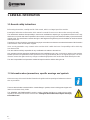 6
6
-
 7
7
-
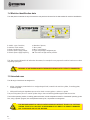 8
8
-
 9
9
-
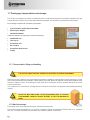 10
10
-
 11
11
-
 12
12
-
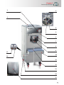 13
13
-
 14
14
-
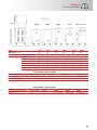 15
15
-
 16
16
-
 17
17
-
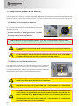 18
18
-
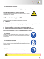 19
19
-
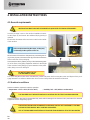 20
20
-
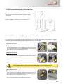 21
21
-
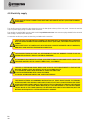 22
22
-
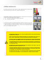 23
23
-
 24
24
-
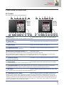 25
25
-
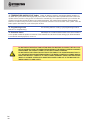 26
26
-
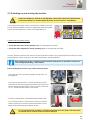 27
27
-
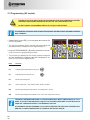 28
28
-
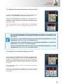 29
29
-
 30
30
-
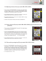 31
31
-
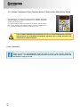 32
32
-
 33
33
-
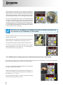 34
34
-
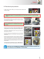 35
35
-
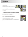 36
36
-
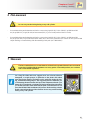 37
37
-
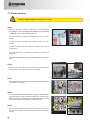 38
38
-
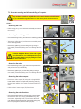 39
39
-
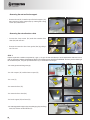 40
40
-
 41
41
-
 42
42
-
 43
43
-
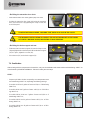 44
44
-
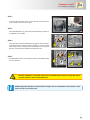 45
45
-
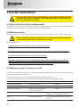 46
46
-
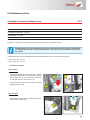 47
47
-
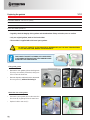 48
48
-
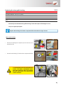 49
49
-
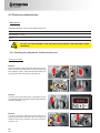 50
50
-
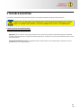 51
51
-
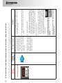 52
52
-
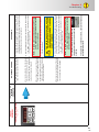 53
53
-
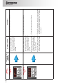 54
54
-
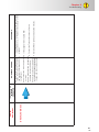 55
55
-
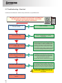 56
56
-
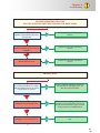 57
57
-
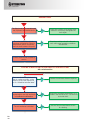 58
58
-
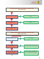 59
59
-
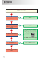 60
60
-
 61
61
-
 62
62
-
 63
63
-
 64
64
-
 65
65
-
 66
66
-
 67
67
-
 68
68
-
 69
69
-
 70
70
-
 71
71
-
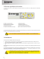 72
72
-
 73
73
-
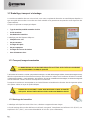 74
74
-
 75
75
-
 76
76
-
 77
77
-
 78
78
-
 79
79
-
 80
80
-
 81
81
-
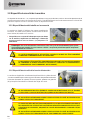 82
82
-
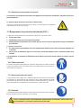 83
83
-
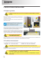 84
84
-
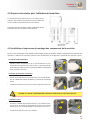 85
85
-
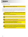 86
86
-
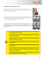 87
87
-
 88
88
-
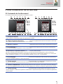 89
89
-
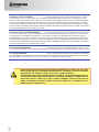 90
90
-
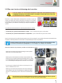 91
91
-
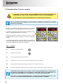 92
92
-
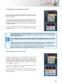 93
93
-
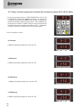 94
94
-
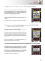 95
95
-
 96
96
-
 97
97
-
 98
98
-
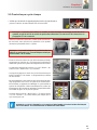 99
99
-
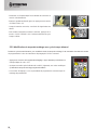 100
100
-
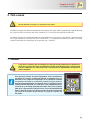 101
101
-
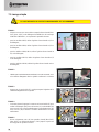 102
102
-
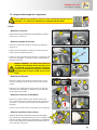 103
103
-
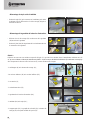 104
104
-
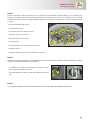 105
105
-
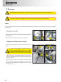 106
106
-
 107
107
-
 108
108
-
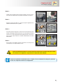 109
109
-
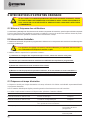 110
110
-
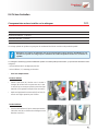 111
111
-
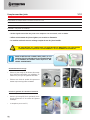 112
112
-
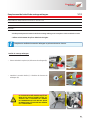 113
113
-
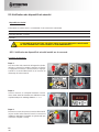 114
114
-
 115
115
-
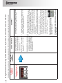 116
116
-
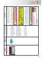 117
117
-
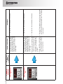 118
118
-
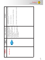 119
119
-
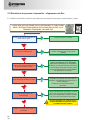 120
120
-
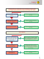 121
121
-
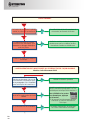 122
122
-
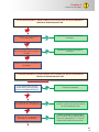 123
123
-
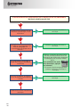 124
124
-
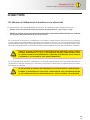 125
125
-
 126
126
-
 127
127
-
 128
128
-
 129
129
-
 130
130
-
 131
131
-
 132
132
-
 133
133
-
 134
134
-
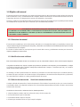 135
135
-
 136
136
-
 137
137
-
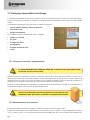 138
138
-
 139
139
-
 140
140
-
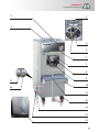 141
141
-
 142
142
-
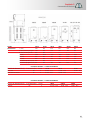 143
143
-
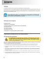 144
144
-
 145
145
-
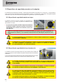 146
146
-
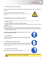 147
147
-
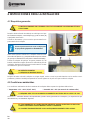 148
148
-
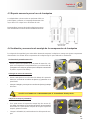 149
149
-
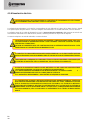 150
150
-
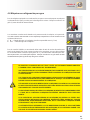 151
151
-
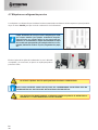 152
152
-
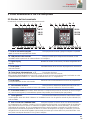 153
153
-
 154
154
-
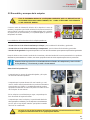 155
155
-
 156
156
-
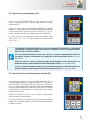 157
157
-
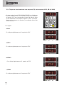 158
158
-
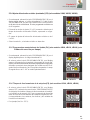 159
159
-
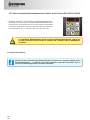 160
160
-
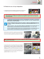 161
161
-
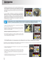 162
162
-
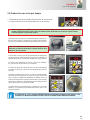 163
163
-
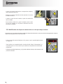 164
164
-
 165
165
-
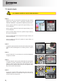 166
166
-
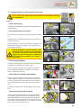 167
167
-
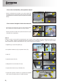 168
168
-
 169
169
-
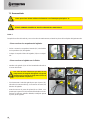 170
170
-
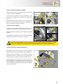 171
171
-
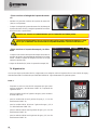 172
172
-
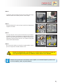 173
173
-
 174
174
-
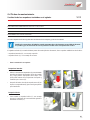 175
175
-
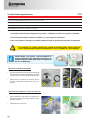 176
176
-
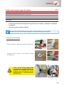 177
177
-
 178
178
-
 179
179
-
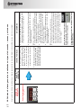 180
180
-
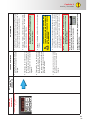 181
181
-
 182
182
-
 183
183
-
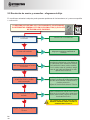 184
184
-
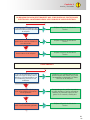 185
185
-
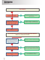 186
186
-
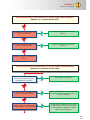 187
187
-
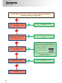 188
188
-
 189
189
-
 190
190
-
 191
191
-
 192
192


Stoelting VB35/VB60/VB80/VB90/VB120/VB160 Manual de usuario
- Tipo
- Manual de usuario
en otros idiomas
Otros documentos
-
Makita XML07Z Manual de usuario
-
-
Philips DTP4800/31 Manual de usuario
-
GE Appliances XPIO13BCBT El manual del propietario
-
Hobart CLPS66eN Instructions Manual
-
SINGER SE340 El manual del propietario
-
Magic Chef MCSTCW21W2 Manual de usuario
-
Beast BEAST7 Guía del usuario
-
Minuteman ROS 17 ORB 115V Manual de usuario
-
Echo WT-1610T Manual de usuario