Simplicity 01923-0 Manual de usuario
- Categoría
- Generadores de poder
- Tipo
- Manual de usuario

Owner’s Manual / Manual del Propietario
Portable Generator / Generador Portátil
Model / Modelo 01923
Manual No. 192411GS Revision 1 (02/05/2003)Printed in USA
Questions? Preguntas?
Helpline - 1-888-611-6708 M-F 8-5 CT
BRIGGS & STRATTON POWER PRODUCTS GROUP, LLC
JEFFERSON, WISCONSIN, U.S.A.
IMPORTANT: READ SAFETY RULES AND INSTRUCTIONS CAREFULLY
IMPORTANTE: LEYO LA SEGURIDAD LAS ORDENES Y LAS INSTRUCCIONES DETENIDAMENTE
Troy-Bilt® is a registered trademark of MTD and is used under license to Briggs & Stratton Power Products.
Troy-Bilt® es una marca registrada registrada de MTD y se usa abajo licencia a Briggs & Stratton Power Products.

2
TABLE OF CONTENTS
Safety Rules. . . . . . . . . . . . . . . . . . . . . . . . . . . . . . . . . . 2-4
Know Your Generator . . . . . . . . . . . . . . . . . . . . . . . . . . . 5
Assembly. . . . . . . . . . . . . . . . . . . . . . . . . . . . . . . . . . . . 6-7
Operation . . . . . . . . . . . . . . . . . . . . . . . . . . . . . . . . . . 8-10
Maintenance . . . . . . . . . . . . . . . . . . . . . . . . . . . . . . . 11-13
Storage . . . . . . . . . . . . . . . . . . . . . . . . . . . . . . . . . . . 13-14
Troubleshooting . . . . . . . . . . . . . . . . . . . . . . . . . . . . . . . 15
Wiring Diagram . . . . . . . . . . . . . . . . . . . . . . . . . . . . . . . 16
Replacement Parts. . . . . . . . . . . . . . . . . . . . . . . . . . . 17-24
Emmision Control System Warranty . . . . . . . . . . . . . . . 25
Warranty . . . . . . . . . . . . . . . . . . . . . . . . . . . . . . . Last Page
EQUIPMENT
DESCRIPTION
Read this manual carefully and become
familiar with your generator. Know its
applications, its limitations and any hazards
involved.
The generators are an engine–driven, revolving field,
alternating current (AC) generator. It was designed to
supply electrical power for operating compatible electrical
lighting, appliances, tools and motor loads. The generator’s
revolving field is driven at about 3,600 rpm by a single-
cylinder engine.
CAUTION! DO NOT exceed the generator’s
wattage/amperage capacity. See “Don’t Overload
Generator” on page 10.
Every effort has been made to ensure that information in this
manual is accurate and current. However, we reserve the
right to change, alter or otherwise improve the product and
this document at any time without prior notice.
The Emission Control System for this generator is warranted
for standards set by the Environmental Protection Agency.
For warranty information refer to the engine owner’s manual.
SAFETY RULES
This is the safety alert symbol. It is used to
alert you to potential personal injury
hazards. Obey all safety messages that follow
this symbol to avoid possible injury or death.
The safety alert symbol ( ) is used with a signal word
(DANGER, CAUTION, WARNING), a pictorial and/or a
safety message to alert you to hazards. DANGER
indicates a hazard which, if not avoided, will result in death
or serious injury. WARNING indicates a hazard which, if
not avoided, could result in death or serious injury.
CAUTION indicates a hazard which, if not avoided, might
result in minor or moderate injury. CAUTION, when
used without the alert symbol, indicates a situation that
could result in equipment damage. Follow safety messages
to avoid or reduce the risk of injury or death.
The engine exhaust from this product contains
chemicals known to the State of California to cause
cancer, birth defects, or other reproductive harm.
WARNING
In the State of California a spark arrester is required by law
(Section 4442 of the California Public Resources Code).
Other states may have similar laws. Federal laws apply on
federal lands. If you equip the muffler with a spark arrester,
it must be maintained in effective working order.
Safety Rules
1
Section

3
• DO NOT allow any open flame, spark, heat, or lit cigarette
during and for several minutes after charging a battery.
• Wear protective goggles, rubber apron, and rubber gloves.
Storage batteries give off explosive hydrogen gas
during recharging.
Hydrogen gas stays around battery for a long
time after battery has been charged.
Slightest spark will ignite hydrogen and cause
explosion.
You can be blinded or severely injured.
Battery electrolyte fluid contains acid and is
extremely caustic.
Contact with battery fluid will cause severe
chemical burns.
DANGER
• Operate generator ONLY outdoors.
• Keep at least 2 feet of clearance on all sides of generator for
adequate ventilation.
• DO NOT operate generator inside any building or enclosure,
including the generator compartment of a recreational vehicle (RV).
Running generator gives off carbon monoxide,
an odorless, colorless, poison gas.
Breathing carbon monoxide will cause nausea,
fainting or death.
DANGER
• When using generator for backup power, notify utility
company. Use approved transfer equipment to isolate
generator from electric utility.
• Use a ground circuit fault interrupter (GFCI) in any damp or
highly conductive area, such as metal decking or steel work.
• DO NOT touch bare wires or receptacles.
• DO NOT use generator with electrical cords which are worn,
frayed, bare or otherwise damaged.
• DO NOT operate generator in the rain.
• DO NOT handle generator or electrical cords while standing
in water, while barefoot, or while hands or feet are wet.
• DO NOT allow unqualified persons or children to operate or
service generator.
Generator produces powerful voltage.
Failure to isolate generator from power utility
can result in death or injury to electric utility
workers due to backfeed of electrical energy.
DANGER
• National Electric Code requires generator to be properly
grounded to an approved earth ground. Call an electrician for
local grounding requirements.
Failure to properly ground generator can result
in electrocution, especially if the generator is
equipped with a wheel kit.
DANGER
WHEN ADDING FUEL
• Turn generator OFF and let it cool at least 2 minutes before
removing gas cap. Loosen cap slowly to relieve pressure in tank.
• Fill fuel tank outdoors.
• DO NOT overfill tank. Allow space for fuel expansion.
• Keep fuel away from sparks, open flames, pilot lights, heat, and
other ignition sources.
• DO NOT light a cigarette or smoke.
WHEN OPERATING EQUIPMENT
• DO NOT tip engine or equipment at angle which causes fuel
to spill.
• This generator is not for use in mobile equipment or marine
applications.
WHEN TRANSPORTING OR REPAIRING EQUIPMENT
• Transport/repair with fuel tank EMPTY or with fuel shutoff
valve OFF.
• Disconnect spark plug wire.
WHEN STORING FUEL OR EQUIPMENT WITH FUEL
IN TANK
• Store away from furnaces, stoves, water heaters, clothes
dryers or other appliances that have pilot light or other
ignition source because they can ignite fuel vapors.
Fuel and its vapors are extremely flammable and
explosive.
Fire or explosion can cause severe burns or
death.
WARNING
Section 1: Safety Rules
• This generator does not meet U. S. Coast Guard Regulation
33CFR-183 and should not be used on marine applications.
• Failure to use the appropriate U. S. Coast Guard approved
generator could result in bodily injury and/or property
damage.
WARNING

4
• DO NOT touch hot surfaces.
• Allow equipment to cool before touching.
Running engines produce heat. Temperature of
muffler and nearby areas can reach or exceed
150°F (65°C).
Severe burns can occur on contact.
WARNING
• DO NOT tamper with governed speed. Generator supplies
correct rated frequency and voltage when running at governed
speed.
• DO NOT modify generator in any way.
Excessively high operating speeds increase risk of injury
and damage to generator.
Excessively low speeds impose a heavy load.
CAUTION
• See “Don’t Overload Generator” on page 10.
• Start generator and let engine stabilize before connecting
electrical loads.
• Connect electrical loads in OFF position, then turn ON for
operation.
• Turn electrical loads OFF and disconnect from generator
before stopping generator.
Exceeding generators wattage/amperage capacity can
damage generator and/or electrical devices connected
to it.
CAUTION
• Use generator only for intended uses.
• If you have questions about intended use, ask dealer or call
1-888-611-6708.
• Operate generator only on level surfaces.
• DO NOT expose generator to excessive moisture, dust, dirt,
or corrosive vapors.
• DO NOT insert any objects through cooling slots.
• If connected devices overheat, turn them off and disconnect
them from generator.
• Shut off generator if:
-electrical output is lost;
-equipment sparks, smokes, or emits flames;
-unit vibrates excessively.
Improper treatment of generator can damage it and
shorten its life.
CAUTION
WHEN ADJUSTING OR MAKING REPAIRS TO YOUR
GENERATOR
• Disconnect the spark plug wire from the spark plug and place
the wire where it cannot contact spark plug.
Unintentional sparking can result in fire or
electric shock.
WARNING
Section 1: Safety Rules

5
12 Volt DC, 8.3 Amp Accessory Jack — May be used
to power 12 Volt DC electrical devices or recharge 12 Volt
DC batteries.
120 Volt AC, 7.5 Amp Receptacles — May be used to
supply electrical power for the operation of 120 Volt AC,
single phase, 60 Hz electrical lighting, appliance, tool and
motor loads.
Air Cleaner — Uses a foam element to limit the amount
of dirt and dust that enters the engine.
Choke Lever — Used to manually provide proper starting
mixture when engine is cold.
Circuit Breaker (AC) — Receptacles are provided with a
push-to-reset circuit breaker to protect the generator
against electrical overload.
Data Tag — Provides model, revision and serial number
of generator. Please have these readily available when calling
for assistance.
Engine ON/OFF Switch — Used to stop a running
engine.
Fuel Shut-Off Valve — Use this valve to turn the fuel
supply on and off.
Fuel Tank — Capacity of 1.2 U.S. gallons (4.5 liters) of
fuel.
Grounding Lug — Use this connection to properly
ground the generator. See ”Grounding the Generator” on
page 7.
Oil Fill/Drain — Access to oil fill dipstick and engine oil
drain plug.
Recoil Starter — Used for starting the engine.
Spark Plug — Access to engine spark plug.
KNOW YOUR GENERATOR
Read this owner’s manual and safety rules before operating your generator.
Compare the illustrations with your generator to familiarize yourself with the locations of various controls and
adjustments. Save this manual for future reference.
120 Volt AC, 7.5 Amp
Receptacle
Recoil Starter
Circuit Breaker (AC)
Oil Fill/Drain
(inside cover)
Choke Lever
Spark Plug (inside
cover)
Fuel Tank
Air Cleaner
Grounding Lug
12 Volt DC, 8.3 Amp
Accessory Jack
Engine ON/OFF Switch
Fuel Shut-Off Valve
Features and Controls
2
Section
Data Tag

6
ASSEMBLY
Carton Contents
Check all contents. If any parts are missing or damaged, call
the generator helpline at 1-888-611-6708. Shipped with
your generator is:
• Main unit
• Oil bottle
• Owner’s manual
• Battery charge cables
BEFORE STARTING ENGINE
Add Oil
NOTE: When adding oil to the engine crankcase in the
future, use only high quality detergent oil rated with API
service classification SG, SF/CC, CD. Select the oil’s
viscosity grade according to your expected operating
temperature:
SAE 10W-30 is recommended for general all temperature
use. Multi-viscosity oils (10W30, etc.) improve starting in
cold weather, but these oils will result in increased oil
consumption. Check your engine oil level more frequently
to avoid possible damage from running low on oil.
To Add Engine Oil:
• Place the generator on a level surface.
• Remove the oil fill cover.
• Remove oil filler cap and wipe dipstick clean (Figure 1).
• If the oil level is not at the point of overflowing from the
oil filler neck, slowly fill engine with recommended oil.
• Reinstall oil filler cap and tighten securely.
• Replace the oil fill cover.
• Check the engine oil level before starting each time
thereafter.
Add Fuel
WARNING! NEVER fill fuel tank indoors. NEVER
fill fuel tank when engine is running or hot. Allow unit
to cool for two minutes before refueling. DO NOT
light a cigarette or smoke when filling the fuel tank.
WARNING! DO NOT overfill the fuel tank.
Always allow room for fuel expansion.
• Use clean fresh UNLEADED fuel with a pump rating of
86 or higher. DO NOT use premium or leaded fuel. DO
NOT mix oil with fuel.
• Clean area around fuel fill cap, remove cap.
• Check the fuel level.
• If fuel level is low, slowly add recommended fuel to fuel
tank, up to the shoulder of the fuel strainer (Figure 2).
Be careful not to overfill (there should be no fuel in the
filler neck).
NOTE: Occasionally clear the fuel strainer of any dirt,
rust, or other particulate matter.
• Install fuel cap and wipe up any spilled fuel.
Occasionally you may hear a light “spark knock” or
“pinging” (metallic rapping noise) while operating under
heavy loads. This is no cause for concern. If spark knock or
pinging occurs at a steady engine speed under normal load,
change brands of fuel or obtain a higher octane rated fuel.
If pinging or spark knock persists, see your local Briggs &
Stratton repair center.
colder 32°F warmer
SAE 10W30 SAE 30
Oil Filler Neck
Figure 1 — Adding Engine Oil
Fill to This Level
Figure 2 — Fuel Level
3
Section
Assembly

7
GROUNDING THE
GENERATOR
The National Electrical Code requires that the frame and
external electrically conductive parts of this generator be
properly connected to an approved earth ground. Local
electrical codes may also require proper grounding of the
unit. For that purpose, a GROUNDING WING NUT is
provided on the generator housing (Figure 3).
Generally, connecting a No. 12 AWG (American Wire
Gauge) stranded copper wire to the grounding wing nut
and to an earth-driven copper or brass grounding rod
(electrode) provides adequate protection against electrical
shock. Be careful to keep the grounding wire attached after
connecting the stranded copper wire. However, local codes
may vary widely. Consult with a local electrician for
grounding requirements in your area.
Properly grounding the generator helps prevent electrical
shock if a ground fault condition exists in the generator or
in connected electrical devices. Proper grounding also helps
dissipate static electricity, which often builds up in
ungrounded devices.
OPERATING THE
GENERATOR
CAUTION! NEVER start or stop the engine with
electrical loads connected to the unit and with the
connected devices turned ON.
Starting the Engine
Disconnect all electrical loads from the generator. Use the
following start instructions:
• Be sure the spark plug wire is attached to the spark plug.
• Turn the fuel valve to the “Open” position (fully
clockwise) (Figure 4).
• Slide the choke lever to the “Choke” position (all the
way to the right) (Figure 5).
• Place the engine switch in the “On” position (Figure 6).
• Grasp starter grip and slowly pull the rope until you feel
some resistance, then pull the cord out with a rapid full
arm stroke. Let rope return slowly. DO NOT let rope
“snap back” against the unit.
Figure 5 — Choke Lever
Figure 4 — Fuel Valve in Open Position
Figure 6 — Engine Switch in On Position
Figure 3 — Grounding Wing Nut
Grounding Wing Nut
4
Section
Operation

8
NOTE: If engine starts after 3 pulls, but fails to run for
more than 10 seconds, check for proper oil level in
crankcase. This unit is equipped with a Oil Alert System
(see page 8).
• Slide the choke lever left to the “Run” position as the
engine warms up.
NOTE: Under no load conditions, the engine speed may
vary slightly faster or slower until engine temperatures
stabilize.
CAUTION! Breathing Hazard! NEVER run
engine in enclosed poorly ventilated areas. Engine
exhaust contains carbon monoxide, an odorless and
deadly gas.
Connecting Electrical Loads
• Let engine stabilize and warm up for a few minutes after
starting.
• DO NOT connect 240 Volt loads to 120 Volt receptacles.
• DO NOT connect 3–phase loads to the generator.
• DO NOT connect 50 Hz loads to the generator.
• Plug in and turn on the desired 120 Volt AC, single
phase, 60 Hertz electrical loads.
• DO NOT OVERLOAD GENERATOR. Add up the
rated watts (or amps) of all loads to be connected at
one time. This total should not be greater than the rated
wattage/amperage capacity of the generator. See “Don’t
Overload Generator” on page 10.
Stopping the Engine
• Unplug all electrical loads from the unit. NEVER start or
stop engine with electrical devices plugged in and turned
on.
• Let engine run at no–load for two minutes to stabilize
the internal temperatures.
• Move engine switch to the “Off” position.
• Turn the fuel valve to the “Close” position (fully
counterclockwise).
NOTE: In an emergency, stop the engine by moving the
engine switch to the “Off” position.
Oil Alert System
The Oil Alert System is designed to prevent engine damage
caused by an insufficient amount of oil in the crankcase.
Before the oil level in the crankcase can fall below a safe
limit, the Oil Alert System will automatically shut down the
engine (the engine switch will remain in the “On” position).
If the Oil Alert System shuts down the engine, add engine
oil.
Charging a Battery
WARNING! Storage batteries emit explosive gas
while charging that remains around a battery for a
long time after it has been charged. The slightest
spark can ignite the gas, causing an explosion that
can shatter the battery and cause blindness or
other injury.
WARNING! DO NOT permit smoking, open
flame, sparks or any other source of heat around a
battery. DO NOT use a lighter or other flame for
checking battery fluid levels. Wear protective
goggles, rubber apron and rubber gloves when
working around a battery. Battery electrolyte fluid is
an extremely caustic sulfuric acid solution that can
cause severe burns. DO NOT permit fluid contact
with eyes, skin, clothing, etc. If spill occurs, flush
area with clear water immediately.
Your generator has the capability of recharging a discharged
12 Volt automotive or utility style storage battery. DO
NOT use the unit to charge any 6 Volt batteries. DO NOT
use the unit to crank an engine having a discharged battery.
To recharge 12 Volt batteries, proceed as follows:
• If necessary, clean battery posts or terminals.
• Check fluid level in all battery cells. If necessary, add
ONLY distilled water to cover separators in battery
cells. DO NOT use tap water.
• If the battery is equipped with vent caps, make sure they
are installed and are tight.
• Connect battery charge cable connector plug to the
12 Volt DC panel receptacle.
• Connect battery charge cable clamp with red handle to
battery post or terminal indicated by Positive, POS or
(+) (Figure 7).
Section 4: Operation

9
• Connect battery charge cable clamp with black handle
to battery post or terminal indicated by Negative,
NEG, or (–) (Figure 7).
• Start generator. Let the engine run while battery
recharges.
• When battery has charged, shut down engine (see
“Stopping The Engine”)
NOTE: Use an automotive hydrometer to test battery
state of charge and condition. Follow the hydrometer
manufacturer’s instructions carefully. Generally, a battery is
considered to be at 100% state of charge when specific
gravity of its fluid (as measured by hydrometer) is 1.260 or
higher.
CONNECTOR PLUGS
120 Volt AC, 15 Amp Receptacle
Each outlet socket is protected against overload by a
7.5 Amp push-to-reset circuit breaker. Use each receptacle
to operate 120 Volt AC, single phase, 60 Hz electrical loads
requiring up to 1,000 watts (1.0 kW) of power (Figure 8).
CAUTION! Although each receptacle is rated
for 120 Volts at 15 Amps (1,440 watts or 1.44 kW),
the generator is rated for a total of 1,000 watts.
Powering loads that exceed the wattage capacity of
the generator can damage it or cause serious
injuries. The total of loads powered through these
receptacles should not exceed 7.5 Amps.
12 Volt DC Accessory Jack
This receptacle allows you to recharge a 12 Volt
automotive or utility style storage battery with the battery
charge cable provided. Camping-style air pumps, lanterns,
fans, or other 12 Volt devices having a cigarette lighter-type
plug may also be powered by this outlet (Figure 9).
This receptacle can not recharge 6 Volt batteries and can
not be used to crank an engine having a discharged battery.
See “Charging a Battery” (page 8) before attempting to
recharge a battery.
EXTENSION CORDS
Use only high quality, well-insulated, extension cords with
the generator’s 120 Volt electrical receptacles.
Check the ratings of all extension cords before you use
them. Such cords should be rated for 125 Volt AC loads at
15 Amps (or greater) for most electrical devices. Some
devices, however, may not require this type of extension
cord. Check the owner’s manuals of those devices for their
recommendations.
Keep extension cords as short as possible, preferably less
than 15 feet long, to prevent voltage drop and possible
overheating of wires.
Figure 8 — 120 Volt AC, 15 Amp Duplex Receptacle
Figure 9 — 12 Volt DC Accessory Jack
Red Lead
To 12 Volt DC Panel
Receptacle
Positive
Negative
Figure 7 — Battery Connections
Section 4: Operation

10
DON'T OVERLOAD
GENERATOR
Capacity
You must make sure your generator can supply enough
rated (running) and surge (starting) watts for the items you
will power at the same time. Follow these simple steps:
1. Select the items you will power at the same time.
2. Total the rated (running) watts of these items. This is
the amount of power your generator must produce to
keep your items running. See Figure 10.
3. Estimate how many surge (starting) watts you will
need. Surge wattage is the short burst of power
needed to start electric motor-driven tools or
appliances such as a circular saw or refrigerator.
Because not all motors start at the same time, total
surge watts can be estimated by adding only the
item(s) with the highest additional surge watts to the
total rated watts from step 2.
Example:
Total Rated (Running) Watts = 3075
Highest Additional Surge Watts = 1800
Total Generator Output Required = 4875
Power Management
To prolong the life of your generator and attached devices,
it is important to take care when adding electrical loads to
your generator. There should be nothing connected to the
generator outlets before starting it's engine. The correct
and safe way to manage generator power is to sequentially
add loads as follows:
1. With nothing connected to the generator, start the
engine as described in this manual.
2. Plug in and turn on the first load, preferably the largest
load you have.
3. Permit the generator output to stabilize (engine runs
smoothly and attached device operates properly.
4. Plug in and turn on the next load.
5. Again, permit the generator to stabilize.
6. Repeat steps 4 and 5 for each additional load.
NEVER add more loads than the generator capacity. Take
special care to consider surge loads in generator capacity,
as described above.
*Wattages listed are approximate only. Check tool or
appliance for actual wattage.
Tool or Appliance
Rated (Running)
Watts
Additional Surge
(Starting) Watts
Window Air
Conditioner
1200 1800
Refrigerator 800 1600
Deep Freezer 500 500
Television 500 -
Light (75 Watts) 75 -
3075 Total
Running Watts
1800 Highest
Surge Watts
Tool or Appliance
Rated*
(Running)
Watts
Additional
Surge
(Starting)
Watts
Essentials
Light Bulb - 75 watt
75
-
Deep Freezer
500
500
Sump Pump
800
1200
Refrigerator/Freezer - 18 Cu. Ft.
800
1600
Water Well Pump - 1/3 HP
1000
2000
Heating/Cooling
Window AC - 10,000 BTU
1200
1800
Window Fan
300
600
Furnace Fan Blower - 1/2 HP
800
1300
Kitchen
Microwave Oven - 1000 Watt
1000
-
Coffee Maker
1500
-
Electric Stove - Single Element
1500
-
Hot Plate
2500
-
Family Room
DVD/CD Player
100
-
VCR
100
-
Stereo Receiver
450
-
Color Television - 27”
500
-
Personal Computer w/17” monitor
800
-
Other
Security System
180
-
AM/FM Clock Radio
300
-
Garage Door Opener - 1/2 HP
480
520
Electric Water Heater - 40 Gallon
4000
-
DIY/Job Site
Quartz Halogen Work Light
1000
-
Airless Sprayer - 1/3 HP
600
1200
Reciprocating Saw
960
960
Electric Drill - 1/2 HP
1000
1000
Circular Saw - 7 1/4”
1500
1500
Miter Saw - 10”
1800
1800
Table Planer - 6”
1800
1800
Table Saw/Radial Arm Saw - 10”
2000
2000
Air Compressor - 1-1/2 HP
2500
2500
Figure 10 - Wattage Reference Chart
Section 4: Operation

11
PRODUCT
SPECIFICATIONS
Generator Specifications
Rated Surge Watts . . . . . . . . . . . . . . . 1,000 Watts
Rated Running Watts . . . . . . . . . . . . . 900 Watts
Rated Maximum Current
At 120 Volts AC . . . . . . . . . . . . . .7.5 Amps
At 12 Volts DC . . . . . . . . . . . . . . .8.3 Amps
Phase . . . . . . . . . . . . . . . . . . . . . . . .Single Phase
Rated Frequency . . . . . . . . . . . . . . . .60 Hertz
Packaged Weight . . . . . . . . . . . . . . . .61 lbs.
Engine Specifications
Model
. . . . . . . . . . . . . . . . . . . . . . . .
Mitsubishi GM82
Rated Horsepower . . . . . . . . . . . . . . 2.4 at 4000 rpm
Displacement . . . . . . . . . . . . . . . . . . . 80cc
Spark Plug Type: . . . . . . . . . . . . . . . . . NGK BP6HS or
equivalent
Set Gap To: . . . . . . . . . . . . . . . . . . . . . 0.030inch (0.75mm)
Fuel Capacity . . . . . . . . . . . . . . . . . . . 1.2 U.S. gallons (4.5 l)
GENERAL MAINTENANCE
RECOMMENDATIONS
The generator warranty does not cover items that have
been subjected to operator abuse or negligence. To receive
full value from the warranty, operator must maintain
generator as instructed in this manual.
Some adjustments will need to be made periodically to
properly maintain your generator.
All adjustments in this section should be made at least
once each season. Follow the requirements in the
“Maintenance Schedule” chart shown below in Figure 11.
NOTE: Once a year you should clean or replace the spark
plug and replace the air filter. A new spark plug and clean
air filter assure proper fuel-air mixture and help your
engine run better and last longer.
GENERATOR
MAINTENANCE
Generator maintenance consists of keeping the unit clean
and dry. Operate and store the unit in a clean dry
environment where it will not be exposed to excessive
dust, dirt, moisture or any corrosive vapors. Cooling air
slots in the generator must not become clogged with snow,
leaves or any other foreign material.
Check the cleanliness of the generator frequently and clean
when dust, dirt, oil, moisture or other foreign substances
are visible on its exterior surface.
NOTE: DO NOT use a garden hose to clean generator.
Water can enter engine fuel system and cause problems. In
addition, if water enters generator through cooling air slots,
some of the water will be retained in voids and cracks of
the rotor and stator winding insulation. Water and dirt
buildup on the generator internal windings will eventually
decrease the insulation resistance of these windings.
1 Clean more often under dirty or dusty conditions. Replace cleaner parts if very dirty.
2 Check every 10 hours or 3 months.
3 These items should be serviced by an authorized dealer, unless the owner has the proper tools and is mechanically
proficient.
Item
Operation
Each use
First Month or
25 hours
Every 3 months
or 50 hours
Every 6 months
or 100 hours
Engine oil
Check level
X
Change
X
X
Air cleaner
Check
X
Clean
X (1)
Spark arrester
Check – Clean
X (2,3)
Spark plug
Check – Clean
X
Valve clearance
Check – Adjust
X (3)
Fuel tank strainer
Clean
X (3)
Fuel line
Check (Replace if
necessary)
Every 3 years (3)
Figure 11 – Maintenance Schedule
Maintenance
5
Section

12
To Clean the Generator
• Use a damp cloth to wipe exterior surfaces clean.
• Soft, bristle brush may be used to loosen caked on dirt
or oil.
CAUTION! NEVER insert any object or tool
through the air cooling slots, even if the engine is
not running.
• A vacuum cleaner may be used to pick up loose dirt and
debris.
• Low pressure air (not to exceed 25 psi) may be used to
blow away dirt. Inspect cooling air slots and opening on
generator. These openings must be kept clean and
unobstructed.
DANGER! When working on the generator
always disconnect spark plug wire from spark plug
and keep it away from spark plug.
ENGINE MAINTENANCE
Checking Oil Level
Oil level should be checked prior to each use or at least
every 5 hours of operation. Keep oil level maintained.
Changing Engine Oil
Change the oil after the first month of operation, then
every 25 hours. If you are using your generator under
extremely dirty or dusty conditions, or in extremely hot
weather, change the oil more often.
Change the oil while the engine is still warm from running,
as follows:
• Remove the oil fill cover and clean area around oil drain
plug (Figure 12).
• Remove oil drain plug, sealing washer, and oil filler cap.
Drain oil completely into a suitable container.
• Install oil drain plug and sealing washer. Tighten securely.
• Refill with recommended oil and check the level. See
page 6 for oil recommendations.
• Wipe up any spilled oil.
CAUTION! Avoid prolonged or repeated skin
contact with used motor oil. Used motor oil has
been shown to cause skin cancer in certain
laboratory animals. Thoroughly wash exposed areas
with soap and water. KEEP OUT OF REACH OF
CHILDREN.
DON'T POLLUTE. CONSERVE RESOURCES.
RETURN USED OIL TO COLLECTION CENTERS.
• Replace oil fill cover.
Clean/Replace Spark Plug
Check and clean the spark plug every 50 hours of
operation or every three months, whichever comes first.
This will help your engine to start easier and run better.
• Remove spark plug access cover. Remove spark plug cap.
• Clean the area around the spark plug.
• Remove and inspect the spark plug.
• Replace the spark plug if electrodes are pitted or burned
or the porcelain is cracked. Use recommended plug for
replacement.
• Check electrode gap with wire feeler gauge and set spark
plug gap between 0.028 and 0.031 inch (0.7 to 0.8 mm) if
necessary (Figure 13).
• Reinstall spark plug.
Service Air Cleaner
Your engine will not run properly and may be damaged if
you run it using a dirty air filter element.
Check the air filter every use and clean or replace the paper
air filter element every 50 hours of operation or every three
months, whichever comes first. Clean or replace more often
if operating under dusty or dirty conditions.
Figure 12 — Oil Drain Plug
Oil Drain Plug
Section 5: Maintenance
Figure 13 — Service Spark Plug

13
To clean or replace air filter element:
• Loosen the air cleaner cover screws, remove the air
cleaner cover, and remove the element (see item
number 4, exploded view on page 21.
• Wipe clean the inside of the filter housing and cover
thoroughly.
• Wash the element in a solution of household detergent
and warm water, then rinse thoroughly. Or wash in
nonflammable or high flash point solvent. Allow the
element to dry thoroughly.
• Soak the element in clean engine oil and squeeze out the
excess oil. DO NOT twist. The engine will smoke during
initial start-up if too much oil is left in the element.
NOTE: If you need to order a new air filter element,
contact your Authorized service center.
• Reinstall the air cleaner element and the cover. Hand
tighten the air cleaner cover screws.
Clean Spark Arrester Screen
The engine muffler is equipped with a removable spark
arrester screen. Inspect and clean the screen every 10 hours
of operation or every three months, as shown in Figure 14:
• Loosen the screw on the muffler tail pipe and remove
the spark arrester screen.
• Use a brass or stiff-bristle brush to remove carbon
deposits from the spark arrester surface.
• Inspect the spark arrester for breaks or tears and
replace it if necessary.
NOTE: If you need to order a new spark arrester, contact
your Authorized service center.
• Install the clean screen in the reverse order of removal.
NOTE: If you use your generator on any forest-covered,
brush-covered or grass-covered unimproved land, it must
have a spark arrester installed. The spark arrester must be
maintained in good condition by the owner/operator.
Data Tag
Data tag information is very important if you need help
from our Customer Service Depatment or an authorized
service dealer.
• The data tag (Figure 9) is located on the heat shield on the
muffler side of the generator. For future reference, please
copy the model, revision, and serial number of the
generator in the space below.
STORAGE INSTRUCTIONS
Transporting and Storage
When transporting the generator, turn the engine switch
to “Off” and the fuel valve to “Close”. Keep the generator
level to prevent fuel spillage.
Spark Arrester
Screen
Muffler Tail Pipe
Spark Arrester
Attachment Screw
Figure 14 – Service Spark Arrester Screen
Section 5 & 6: Maintenance & Storage
Figure 9 — Data Tag
Copy Model
Number Here
Copy Revision
Here
Copy Serial
Number Here

14
WARNING! Contact with a hot engine or
exhaust system can cause serious burns or fires. Let
the engine cool before transporting or storing the
generator.
Take care to not drop or strike the generator when
transporting. DO NOT place heavy objects on the
generator.
The generator should be started at least once every seven
days and allowed to run at least 30 minutes. If this cannot
be done and you must store the unit for more than 30 days,
use the following guidelines to prepare it for storage.
Long Term Storage Instructions
WARNING! NEVER store engine with fuel in
tank indoors or in enclosed, poorly ventilated areas
where fumes may reach an open flame, spark or
pilot light as on a furnace, water heater, clothes
dryer or other gas appliance.
Be sure the storage area is free from excessive
humidity and dust.
One Month to One Year
Drain the carburetor float bowl (see following section) and
fuel tank into a suitable container. After removal from
storage, fill with fresh fuel before starting.
More than One Year
It is important to prevent gum deposits from forming in
essential fuel system parts such as the carburetor, fuel filter,
fuel hose or tank during storage. Also, experience indicates
that alcohol-blended fuels (called gasohol, ethanol or
methanol) can attract moisture, which leads to separation
and formation of acids during storage. Acidic gas can
damage the fuel system of an engine while in storage.
To avoid engine problems, the fuel system should be
emptied before storage of 30 days or longer. Follow these
instructions:
Protect Fuel System
WARNING! Drain fuel into approved container
outdoors, away from open flame. Be sure engine is
cool. DO NOT smoke.
• Drain carburetor float bowl and fuel tank into a suitable
container by loosening the drain screw (Figure 15).
• Retighten drain screw before refueling.
Change Oil
While engine is still warm, change oil as described on
page 12. Refill with recommended grade.
Oil Cylinder Bore
• Remove spark plug and pour about one tablespoon of
clean engine oil into the cylinder.
CAUTION! Avoid spray from spark plug hole
when cranking engine slowly.
• Cover spark plug hole with rag. Crank slowly several
times to distribute oil.
• Install spark plug. DO NOT connect spark plug wire.
• Slowly pull the starter grip until resistance is felt. At this
point, the piston is coming up on its compression stroke
and both the intake and exhaust valves are closed.
Storing the engine in this position will help to protect it
from internal corrosion.
Generator
• Clean the generator as outlined on page 12 (“To Clean
the Generator”).
• Check that cooling air slots and openings on generator
are open and unobstructed.
Other Storage Tips
• DO NOT store fuel from one season to another.
• Replace the fuel can if it starts to rust. Rust and/or dirt
in fuel will cause problems.
• If possible, store your unit indoors. BE SURE TO
EMPTY THE FUEL TANK.
• Cover your unit with a suitable protective cover that
does not retain moisture.
IMPORTANT: NEVER cover your generator while engine
and exhaust area are warm.
• Store generator in clean, dry area.
Carburetor Fuel
Drain Screw
Drain Screw
Access Hole
Figure 15 – Drain Fuel From Carburetor
Storage
6
Section

15
TROUBLESHOOTING
Problem
Cause
Correction
No AC or DC output
is available but
engine is running.
1. One of the circuit breakers is open.
2. Fault in generator.
3. Poor connection or defective cord set.
4. Connected device is bad.
1. Reset circuit breaker.
2. Contact Authorized service facility.
3. Check and repair.
4. Connect another device that is in
good condition.
Generator runs good
at no-load but
“bogs down" when
loads are
connected.
1. Short circuit in a connected load.
2. Engine speed is too slow.
3. Generator is overloaded.
4. Shorted generator circuit.
1. Disconnect shorted electrical load.
2. Contact Authorized service facility.
3. See “Don't Overload Generator”.
4. Contact Authorized service facility.
Engine will not start;
or starts and runs
rough.
1. Engine switch set to “Off”.
2. Dirty air cleaner.
3. Out of gasoline.
4. Stale gasoline.
5. Spark plug wire not connected to spark
plug.
6. Bad spark plug.
7. Water in gasoline.
8. Overchoked or flooded.
9. Excessively rich fuel mixture.
10. Intake valve stuck open or closed.
11. Engine has lost compression.
1. Set switch to “On”.
2. Clean or replace air cleaner.
3. Fill fuel tank.
4. Drain gas tank and carburetor; fill
with fresh fuel.
5. Connect wire to spark plug.
6. Replace spark plug.
7. Drain gas tank and carburetor; fill
with fresh fuel.
8. Wait 5 minutes and re-crank engine.
9. Contact Authorized service facility.
10. Contact Authorized service facility.
11. Contact Authorized service facility.
Engine shuts down
when running.
Out of gasoline.
Fill fuel tank.
Engine lacks power.
1. Load is too high.
2. Dirty air filter.
1. See “Don't Overload Generator”.
2. Replace air filter.
Engine “hunts” or
falters.
Carburetor is running too rich or too lean.
Contact Authorized service facility.
7
Section
Troubleshooting

16
WIRING DIAGRAM
8
Section
Wiring Diagram

17
EXPLODED VIEW AND PARTS LIST – MAIN UNIT
Item Part # Qty Description
1 NSP 1 ENG, MITSUB, 2.4HP
2 187378GS 1 ROTOR
3 187411GS 1 BRG
4 187379GS 1 STATOR
5 187430GS 1 LEAD, GREEN
6 187409GS 1 BUSHING, LEAD WIRE
7 187381GS 1 RBC, 1K
8 187399GS 3 SCREW, SELF TAP
9 187382GS 1 FAN, COOLING
10 187388GS 1 BOLT, RTR
11 187389GS 3 BOLT, STATOR
12 187405GS 1 INSLTN, HEAT SEALED
13 187384GS 1 MFFLR, SEALED
14 187407GS 1 INSLTN, HEAT SEALED
15 187403GS 1 DUCT, AIR
Item Part # Qty Description
16 187392GS 2 SCREW
17 187383GS 1 BASE, GEN
18 187390GS 4 BOLT, FLNG
19 187385GS 4 MNT, VIBR
20 187427GS 4 SCREW
21 187424GS 1 NUT, WING
22 187423GS 1 NUT
23 187419GS 2 WSHR, LOCK
24 187420GS 2 WSHR
25 187401GS 2 NUT, FLANGE
26 187415GS 1 SCREW
27 187413GS 2 CNNCTR
28 187434GS 4 HHCS, FLNG
29 187431GS 1 STND, ENG
9
Section
Exploded Views and Parts Lists

18
Item Part # Qty Description
1 187436GS 1 CAP, FUEL
2 187439GS 1 PACKING, TANK
3 187438GS 1 FLTR, FUEL
4 187769GS 3 U-PACKING
5 187437GS 1 TANK, FUEL, 4.5L
6 187766GS 1 DECAL, CHOKE
7 187756GS 4 BOLT, COVER
8 187433GS 1 HSG, GEN, MFFLR
10 187772GS 1 COVER, SPARK PLUG
11 187757GS 5 BOLT, COVER
12 187760GS 11 SCREW
13 187435GS 1 CVR, MFFLR, GEN
14 187775GS 3 BOLT, MFFLR CVR
15 191436GS 1 DECAL CAUTION HOT
16 187774GS 4 BOLT, COVER
17 187761GS 8 NUT
18 187463GS 1 INSLTN, MFFLR
19 187432GS 1 HSG, GEN
20 NSP 1 DECAL, EMISSIONS
21 187457GS 1 CONDENSER
22 191528GS 1 DECAL, WARNING
23 187759GS 2 BOLT, COVER
24 187462GS 1 DIODE, BRIDGE
Item Part # Qty Description
25 187371AGS 1 BOTTLE, OIL
26 192413GS 1 DECAL, LWR PANEL
27 187773GS 1 COVER, OIL FILL
28 187460GS 1 CB, DC
29 187454GS 1 CB
30 187873GS 1 OUTLET, ACCESSORY DC
31 187450GS 1 SWITCH, ENG, ON/OFF
32 187812GS 1 CPNL
33 187456GS 1 RECPTCL, 15A, 125V
34 187763GS 1 DECAL, CAUTION OIL
35 187876GS 1 CABLE, BATTERY CHARGE
36 192412GS 1 DECAL, UNIT
37 191545GS 1 DECAL, FUEL SHUTOFF
38 187447GS 1 INSLTN, HTSHLD, TANK
39 187448GS 1 INSLTN, HTSHLD, TANK
40 187442GS 2 BRKT, TANK, FUEL
41 187758GS 1 BRKT, FUEL COCK
42 187443GS 1 COCK, FUEL
43 187770GS 1 SCREW
44 187579GS 1 CLIP, FUEL HOSE
45 187440GS 1 FLTR, FUEL
46 187578GS 1 HOSE, FUEL
EXPLODED VIEW AND PARTS LIST – MAIN UNIT
Section 9: Exploded Views and Parts Lists

19
EXPLODED VIEW AND PARTS LIST – ENGINE
Cylinder Block, Cylinder Head
Item Part # Qty Description
1 187404GS 1 ASSY, CYL HEAD
2 187406GS 2 TPPT, CYL HEAD
3 187408GS 2 VLV, EXH
4 187410GS 2 SPRNG, VLV
5 187412GS 2 RTNR, VLV SPG
6 187414GS 2 ROD, PUSH
7 187416GS 1 ASSY, RCKR, ARM
8 187417GS 2 NUT, CYL HEAD
9 187418GS 2 SCRW, ADJST
10 187421GS 1 PLT, CYL HEAD
Item Part # Qty Description
11 187422GS 1 SEAL, VLV STEM
12 187423GS 4 NUT, M5 X 0.8
13 187426GS 4 BOLT, FLNG
14 187428GS 2 PIN, DWL
15 187429GS 1 GSKT, HEAD
16 187468GS 1 CVR, VALVE
17 187470GS 4 BOLT, VALVE CVR
18 187472GS 1 GSKT, VALVE CVR
19 187569GS 2 BOLT, STUD
Item Part # Qty Description
1 187380GS 1 BLOCK, CYL
2 187386GS 1 ASSY, GOV, GEAR
3 187387GS 1 SLIDER, GOV
4 187391GS 1 SHFT, GOV
5 187393GS 2 PLUG, DRAIN
6 187394GS 2 SEAL, OIL
7 187395GS 1 BRG, BALL
8 187400GS 1 WSHR, CYLBLOCK
9 187402GS 2 GSKT, CYLBLOCK
Section 9: Exploded Views and Parts Lists

20
EXPLODED VIEW AND PARTS LIST – ENGINE
Crankcase Cover, Crankshaft/Camshaft
Item Part # Qty Description
1 187394GS 2 SEAL, OIL
2 187473GS 1 CVR, CRANKCASE
3 187474GS 1 DIPSTICK, OIL
4 187475GS 1 O-RING, DIPSTICK
5 187477GS 1 BRG, PTO
6 187478GS 6 BOLT, CRANKCASE CVR
7 187428GS 2 PIN, DWL
8 187479GS 1 GSKT, CRANKCASE CVR
Item Part # Qty Description
1 187481GS 1 ASSY, CRNKSHFT
2 187484GS 1 GEAR, CRNKSHFT
3 187486GS 2 KEY, WOODRFF
4 187487GS 1 GEAR, CRNKSHFT
6 187488GS 1 ASSY, CAMSHAFT
7 187489GS 1 PIN, CMPR REL
8 187490GS 1 RNG, SNP, CMPRSSN
REL
Section 9: Exploded Views and Parts Lists

21
EXPLODED VIEW AND PARTS LIST – ENGINE
Piston/Rod, Magneto/Flywheel, Air Cleaner
Item Part # Qty Description
1 187526GS 1 ROD, CNNCTNG, STD
1 187527GS 1 ROD, CNNCTNG, US.25
1 187528GS 1 ROD, CNNCTNG, US.50
2 187529GS 2 BOLT, CNNCTNG ROD
3 187530GS 1 ASSY, PSTN, STD
3 187531GS 1 ASSY, PSTN, OS.25
3 187532GS 1 ASSY, PSTN, OS.50
4 187533GS 1 PIN, PISTON
5 187534GS 1 SET, RING, PSTN, STD
5 187535GS 1 SET, RING, PSTN, OS.25
5 187537GS 1 SET, RING, PSTN, OS.50
6 187539GS 2 CLIP, SPRING, PSTN PIN
Item Part # Qty Description
1 187540GS 1 FLYWHL
2 187541GS 1 COIL, IGNITION
3 187543GS 1 FAN
4 187544GS 1 CLIP, MAGNETO
5 187545GS 2 BOLT, MAGNETO
6 187546GS 1 NUT
Item Part # Qty Description
1 187492GS 1 HSNG, AIR CLNR
2 187494GS 1 CVR, AIR CLNR
3 187496GS 1 SPRT, AIR CLNR
4 187497GS 1 ELEMENT, AIR CLNR
5 187498GS 1 BRTHR, AIR CLNR
6 187500GS 2 STUD, AIR CLNR
7 187501GS 2 SCREW, AIR CLNR CVR
8 187503GS 2 NUT, AIR CLNR CVR
9 187504GS 1 GSKT, CARB
10 187576GS 1 DECAL, CHOKE
Section 9: Exploded Views and Parts Lists

22
EXPLODED VIEW AND PARTS LIST – ENGINE
Carburetor, Control/Linkages
Item Part # Qty Description
1 187469GS 1 CARB, COMPLETE
2 187471GS 1 JET, MAIN
3 187476GS 1 SHFT, THROTTL
4 187480GS 1 VLV, NEEDLE
5 187482GS 1 CLIP, CARB
6 187483GS 1 PIN, CARB
7 187485GS 1 VLV, THRTTL
8 187491GS 3 HHCS, CARB
9 187493GS 1 VLV, CHOKE
10 187495GS 1 GSKT, CARB
11 187499GS 1 CHMBR, FLOAT
12 187502GS 1 SPRING, CARB
13 187509GS 1 HHCS, CARB
14 187511GS 1 GSKT, CARB
15 187525GS 1 BOLT, CARB
16 187536GS 1 FLOAT, CARB
17 187538GS 1 NZZL, MAIN, CARB
18 187542GS 1 HHCS, CARB
19 187502GS 1 SPRING, CARB
20 187547GS 1 ADJSTR, CARB
21 187548GS 1 LEVER, CHOKE
22 187549GS 1 JET, PILOT
23 187550GS 1 SPRING, CARB
24 187551GS 1 CAP, CARB
25 187552GS 2 PACKING, CARB
26 187553GS 1 SEAL, CARB
27 187554GS 1 SEAL, CARB
28 187556GS 1 INSLTR, CARB
29 187504GS 2 GSKT, CARB
Item Part # Qty Description
1 187505GS 1 BRKT, SPEED CNTRL
2 187506GS 1 SPRING, SPEED CNTRL
3 187507GS 1 SCREW, SPEED CNTRL
4 187508GS 1 SHFT, GOV
5 187510GS 1 RING, SNAP, GOV ROD
6 187512GS 1 LEVER, GOV
7 187513GS 1 ROD, GOV
8 187514GS 1 SPRING, GOV LEVER
9 187515GS 1 WSHR, GOV LEVER
10 187516GS 1 CVR, TOP
11 187517GS 1 CLIP, GOV ROD
12 187518GS 1 BOLT, SPEED CNTRL BKT
13 187519GS 1 BOLT, TOP CVR
14 187520GS 2 NUT, GOV LEVER
15 187570GS 1 SPRING, GOV
Section 9: Exploded Views and Parts Lists

23
EXPLODED VIEW AND PARTS LIST – ENGINE
Fan Cover, Recoil Starter, Oil Sensor
Item Part # Qty Description
1 187521GS 1 CVR, FAN
2 187522GS 1 CVR, FAN
3 187523GS 1 CVR, FAN
4 187524GS 4 BOLT, FAN CVR
Item Part # Qty Description
1 187557GS 1 ASSY, RECOIL, STRTR
2 187558GS 1 STRTR, RECOIL
3 187559GS 1 ROPE, RECOIL
4 187560GS 1 HNDL, RECOIL
5 187561GS 1 PULLEY, STRTR
6 187562GS 3 BOLT, FLNG
Item Part # Qty Description
1 187563GS 1 CLAMP, OILSNSR
2 187564GS 1 SNSR, OIL
3 187565GS 1 UNIT, OILSNSR
4 187566GS 1 WIRE, LEAD
5 187567GS 1 BAND, OILSNSR
6 187470GS 2 BOLT, VALVE CVR
7 187524GS 1 BOLT, FAN CVR
8 187568GS 1 BOLT, FLNG
Section 9: Exploded Views and Parts Lists

24
EXPLODED VIEW AND PARTS LIST – ENGINE
Lead Wires, Muffler, Gasket Set
Item Part # Qty Description
1 187571GS 1 WIRE, LEAD
2 187572GS 1 PLUG, SPARK
3 187573GS 1 CAP, PLUG
4 187574GS 1 TIEWRAP, LEAD WIRE
5 187575GS 1 WIRE, LEAD
Item Part # Qty Description
1 187449GS 3 NUT, FLNG
2 188261GS 1 PIPE, TAIL
3 187446GS 1 GSKT, MFFLR
4 187455GS 2 NUT, CONICAL
5 187451GS 1 GSKT, MFFLR
6 187444GS 1 MFFLR
7 188263GS 1 SCREEN, SPARK
8 188262GS 1 SCREW
Item Part # Qty Description
1 187461GS 1 SET, GSKT (Includes items 2-6)
2 187429GS 1 GSKT, HEAD
3 187472GS 1 GSKT, VALVE CVR
4 187479GS 1 GSKT, CRANKCASE CVR
5 187504GS 3 GSKT, CARB
6 187451GS 1 GSKT, MFFLR
Section 9: Exploded Views and Parts Lists

EMISSION CONTROL SYSTEM WARRANTY
EMISSION CONTROL WARRANTY COVERAGE IS
APPLICABLE TO CERTIFIED ENGINES PURCHASED IN
CALIFORNIA IN 1995 AND THEREAFTER WHICH ARE USED
IN CALIFORNIA, AND TO CERTIFIED MODEL YEAR 1997
AND LATER ENGINES WHICH ARE PURCHASED AND USED
ELSEWHERE IN THE UNITED STATES (AND AFTER JANUARY
1, 2001 IN CANADA).
California and U.S. EPA Emission Control Warranty
Statement Your Warranty Rights and Obligations
The California Air Resources Board (CARB), U.S.EPA and Briggs
& Stratton Power Products (BSPP) are pleased to explain the
Emission Control System Warranty on your model year 2000 and
later small off-road engine (SORE). In California, new small off-
road engines must be designed, built and equipped to meet the
State's stringent anti-smog standards. Elsewhere in the United
States, new non-road, spark-ignition engines certified for model
year 1997 and later, must meet similar standards set forth by the
U.S.EPA. BSPP must warrant the emission control system on your
engine for the periods of time listed below, provided there has
been no abuse, neglect, or improper maintenance of your small
off-road engine.
Your emission control system may include parts such as the
carburetor or fuel-injection system, the ignition system, and
catalytic converter. Also included may be hoses, belts, connectors
and other emission related assemblies.
Where a warrantable condition exists, BSPP will repair your small
off-road engine at no cost to you including diagnosis, parts and
labor.
BSPP Emission Control Defects Warranty Coverage
The 1995 and later small off-road engines are warranted for two
years. If any emission-related part on your engine is defective, the
part will be repaired or replaced by BSPP.
Owner's Warranty Responsibilities
As the small off-road engine owner, you are responsible for the
performance of the required maintenance listed in this owner's
manual. BSPP recommends that you retain all your receipts
covering maintenance on your small off-road engine, but BSPP
cannot deny warranty solely for the lack of receipts or for your
failure to ensure the performance of all scheduled maintenance.
As the small off-road engine owner, you should however be aware
that BSPP may deny you warranty coverage if your small off-road
engine or a part has failed due to abuse, neglect, improper
maintenance or unapproved modifications.
You are responsible for presenting your small off-road engine to
an approved BSPP Service Center as soon as a problem exists.
The warranty repairs should be completed in a reasonable
amount of time, not to exceed 30 days.
If you have any questions regarding your warranty rights and
responsibilities, you should contact a BSPP Service Representative
at 1-800-743-4115.
BSPP Emission Control Defects Warranty Provisions
The following are specific provisions relative to your Emission
Control Defects Warranty Coverage.
1. Warranted Parts
Coverage under this warranty extends only to the parts listed
below (the emission control systems parts) to the extent these
parts were present on the engine purchased.
a. Fuel Metering System
Cold start enrichment system
Carburetor and internal parts
Fuel Pump
b. Air Induction System
Air cleaner
Intake manifold
c. Ignition System
Spark plug(s)
Magneto ignition system
d. Catalyst System
Catalytic converter
Exhaust manifold
Air injection system or pulse valve
e. Miscellaneous Items Used in Above Systems
Vacuum, temperature, position, time sensitive valves and
switches
Connectors and assemblies
2. Length of Coverage
BSPP warrants to the initial owner and each subsequent
owner that the Warranted Parts shall be free from defects in
materials and workmanship which caused the failure of the
Warranted Parts for a period of two years from the date the
engine is delivered to a retail purchaser.
3. No Charge
Repair or replacement of any Warranted Part will be
performed at no charge to the owner, including diagnostic
labor which leads to the determination that a Warranted Part
is defective, if the diagnostic work is performed at an
approved BSPP Service Center.
4. Claims and Coverage Exclusions
Warranty claims shall be filed in accordance with the
provisions of the BSPP Warranty Policy. Warranty coverage
shall be excluded for failures of Warranted Parts which are
not original BSPP parts or because of abuse, neglect or
improper maintenance as set forth in the BSPP Engine
Warranty Policy. BSPP is not liable to cover failures of
Warranted Parts caused by the use of add-on, non-original, or
modified parts.
5. Maintenance
Any Warranted Part which is not scheduled for replacement
as required maintenance or which is scheduled only for
regular inspection to the effect of "repair or replace as
necessary" shall be warranted as to defects for the warranty
period. Any Warranted Part which is scheduled for
replacement as required maintenance shall be warranted as to
defects only for the period of time up to the first scheduled
replacement for that part. Any replacement part that is
equivalent in performance and durability may be used in the
performance of any maintenance or repairs. The owner is
responsible for the performance of all required maintenance,
as defined in this owner's manual.
6. Consequential Coverage
Coverage hereunder shall extend to the failure of any engine
components caused by the failure of any Warranty Part still
under warranty.
Briggs & Stratton Power Products (BSPP), the California Air Resources Board (CARB) and
the United States Environmental Protection Agency (U.S.EPA)
Emission Control System Warranty Statement
(Owner's Defect Warranty Rights and Obligations)
In the USA and Canada, a 24-hour hotline, 1-800-233-3723, has a menu of pre-recorded messages offering you product maintenance
information.

26
TABLA DE CONTENIDOS
Reglas De Seguridad . . . . . . . . . . . . . . . . . . . . . . . . . . . . . . 26-28
Conozca Su Generador . . . . . . . . . . . . . . . . . . . . . . . . . . . . . . 29
Ensamblaje. . . . . . . . . . . . . . . . . . . . . . . . . . . . . . . . . . . . . . 30-31
Funcionamiento . . . . . . . . . . . . . . . . . . . . . . . . . . . . . . . . . . 32-34
Mantenimiento. . . . . . . . . . . . . . . . . . . . . . . . . . . . . . . . . . . 35-37
Almacenamiento . . . . . . . . . . . . . . . . . . . . . . . . . . . . . . . . . 37-38
Notas . . . . . . . . . . . . . . . . . . . . . . . . . . . . . . . . . . . . . . . . . 39-40
Diagnosticos De Averías. . . . . . . . . . . . . . . . . . . . . . . . . . . . . . 41
Digrama Eléctrico. . . . . . . . . . . . . . . . . . . . . . . . . . . . . . . . . . . 16
Piezas De Recambio . . . . . . . . . . . . . . . . . . . . . . . . . . . . . . 17-24
Garantia Del Sistema De Control De Emisiones . . . . . . . . . . . 42
Garantia . . . . . . . . . . . . . . . . . . . . . . . . . . . . . . . . . . . . . . . . . . 43
DESCRIPCIÓN DEL EQUIPO
Lea este manual de manera cuidadosa y
familiarícese con su generador. Conozca sus usos,
sus limitaciones y cualquier peligro relacionado
con el mismo.
Este generador funciona en base a un motor, de campo eléctrico
giratorio y de corriente alterna (AC). Fue diseñado con la
finalidad de proveer energía eléctrica para luces eléctricas,
aparatos, herramientas compatibles y cargas de motor. El campo
giratorio del generador funciona a una velocidad de 3,6000 rpm
usando un motor con un solo cilindro.
¡PRECAUCIÓN! NO sobrepase la capacidad de vataje y
amperaje del generador. Revise "No Sobrecargue el Generador"
en la página 34.
Se ha hecho cada esfuerzo posible para asegurarse que la
información que aparece en este manual es exacta y se encuentra
actualizada. Sin embargo, nosotros se reserva el derecho a
cambiar, alterar o de otra manera mejorar, el producto y este
documento en cualquier momento, sin previo aviso.
El Sistema de Control de Emisiones para este generador está
garantizado para juegos estándares por la Agencia de Protección
Ambiental. Para mayor información acerca de la garantía, consulte
con el manual del propietario del motor.
INSTRUCCIONES DE SEGURIDAD
Éste es el símbolo de alerta de seguridad. Sirve
para advertir al usuario de un posible riesgo para
su integridad física. Siga todos los mensajes de
seguridad que figuren después de este símbolo
para evitar lesiones o incluso la muerte.
El símbolo de alerta de seguridad ( ) es usado con una palabra
(PELIGRO, ADVERTENCIA, PRECAUCIÓN), un mensaje por
escrito o una ilustración, para alertarlo acerca de cualquier
situación de peligro que pueda existir. PELIGRO indica un riesgo
el cual, si no se evita, causará la muerte o una herida grave.
ADVERTENCIA indica un riesgo el cual, si no se evita, puede
causar la muerte o una herida grave. PRECAUCIÓN indica un
riesgo, el cual, si no se evita, puede causar heridas menores o
moderadas. PRECAUCIÓN, cuando se usa sin el símbolo de
alerta, indica una situación que podría resultar en el daño del
equipo. Siga los mensajes de seguridad para evitar o reducir los
riesgos de heridas e inclusive la muerte.
El escape del motor de este producto contiene
elementos químicos reconocidos en el Estado de
California por producir cáncer, defectos de nacimiento u
otros daños de tipo reproductivo.
ADVERTENCIA
En el estado de California es obligatorio, según la ley, el uso de
apagachispas (Sección 4442 del Código de Recursos Públicos de
California). Otros estados pueden tener leyes similares. Las leyes
federales se aplican en tierras federales. Si equipa el silenciador
con un apagachispas, este deberá ser mantenido en buenas
condiciones de trabajo.
Reglas de Seguridad
1
Sección

27
Sección 1: Instrucciones de Seguridad
• NO permita ninguna llama abierta, chispa, calor, o encienda un
cigarrillo durante y por varios minutos después de haber recargado la
batería.
• Lleve puestos las gafas protectoras, delantal y guantes de goma.
Las baterías almacenadas producen hidrógeno
explosivo mientras estén siendo recargadas.
El hidrógeno puede permanecer cerca de la batería
por un periodo largo de tiempo, después que la
batería haya sido recargada.
Una pequeña chispa puede encender el hidrógeno y
causar una explosión.
Usted puede quedar ciego o sufrir heridas muy graves.
El fluido de electrolito de la batería contiene ácido y
es extremadamente cáustico.
El contacto con el fluido de la batería puede causar
quemaduras químicas severas.
PELIGRO
• Opere el generador SOLAMENTE al aire libre.
• Mantenga al menos 2 pies de espacio libre alrededor del generador,
para la adecuada ventilación.
• NO opere el generador dentro de un edificio o lugar cerrado, incluyendo
el compartimiento del generador en un vehículo recreativo o RV.
Al generador funcionar, se produce monóxido de
carbono, un gas inodoro y venenoso.
El respirar el monóxido de carbono, producirá
náusea, desmayo o la muerte.
PELIGRO
• Cuando use un generador como poder de energía auxiliar, notifique a
la compañía de utilidades. Use el equipo de transferencia aprobado
para aislar el generador de otra utilidad eléctrica.
• Use un interruptor para la falla del circuito de tierra (GFCI) en
cualquier área bastante húmeda o que sea altamente conductiva, tales
como terrazas de metal o trabajo hecho con acero.
• NO toque los alambres pelados o receptáculos.
• NO use un generador con cables eléctricos que estén malgastados,
rotos, pelados o dañados de cualquier forma.
• NO opere el generador bajo la lluvia.
• NO maneje el generador o cables eléctricos mientras esté parado en
agua, descalzo o cuando las manos y los pies estén mojados.
• NO permita que personas descalificadas o niños operen o sirvan al
generador.
Los generadores producen un voltaje muy poderoso.
Si no aísla el generador de utilidades de energía,
puede hacer que los trabajadores de electricidad
sufran heridas graves e inclusive la muerte, debido a
la retroalimentación de la energía eléctrica.
PELIGRO
• Los Códigos Nacionales para la Electricidad, requieren que los
generadores estén haciendo tierra de una manera aprobada. Llame a
un electricista para conocer los requisitos locales para hacer tierra.
Si no hace tierra apropiadamente con un generador,
puede hacer que ocurra un electrocutamiento,
especialmente si el generador se equipa con un juego
de la rueda.
PELIGRO
CUANDO AÑADA COMBUSTIBLE
• Apague el generador (posición OFF) y déjelo enfriar al menos por
2 minutos antes de remover la tapa de la gasolina. Afloje la tapa
lentamente para dejar que la presión salga del tanque.
• Llene el tanque al aire libre.
• NO llene demasiado el tanque. Permita al menos espacio para la
expansión del combustible.
• Mantenga la gasolina alejada de chispas, llamas abiertas, pilotos, calor
y otras fuentes de ignición.
• NO encienda un cigarrillo o fume.
CUANDO OPERE EL EQUIPO
• NO incline el motor o el equipo, de tal manera que la gasolina se
pueda derramar.
• Este generador no es apto para el uso en equipos móviles ni en
aplicaciones marinas.
CUANDO TRANSPORTE O REPARE EL EQUIPO
• Transporte o repare el equipo con el tanque de combustible vacío, o
con la válvula para apagar el combustible, apagada (posición OFF).
• Desconecte el cable de la bujía.
CUANDO ALMACENE O GUARDE EL EQUIPO CON
COMBUSTIBLE EN EL TANQUE
• Almacene alejado de calderas, estufas, calentadores de agua,
secadoras de ropa u otros aparatos electrodomésticos que posean
pilotos u otras fuentes de ignición, porque ellos pueden encender los
vapores de la gasolina.
La gasolina y sus vapores son extremadamente
inflamables y explosivos.
El fuego o una explosión pueden causar quemaduras
severas e inclusive la muerte.
ADVERTENCIA
• Este generador no cumple la norma 33CFR-183 del cuerpo de
guardacostas de EE.UU. y no debe utilizarse en aplicaciones marinas.
• El uso de un generador no homologado por cuerpo de guardacostas
de EE.UU. puede provocar lesiones y daños materiales.
ADVERTENCIA

28
Sección 1: Instrucciones de Seguridad
• Vea "No sobrecargue generador" en la página 34.
• Encienda su generador y deje que el motor se estabilice antes de
conectar las cargas eléctricas.
• Conecte las cargas eléctricas en la posición de apagado (OFF), luego
encienda (ON) para su operación.
• Apague (OFF) las cargas eléctricas y desconéctelas del generador
antes de parar el generador.
El sobrepasar la capacidad del amperaje y vataje del
generador, puede dañar al generador y los aparatos
eléctricos conectados al mismo.
PRECAUCIÓN
• Use el generador solamente con la finalidad para el cual fue diseñado.
• Si usted tiene alguna pregunta acerca de las finalidades de uso del
generador, póngase en contacto con el servicio técnico autorizado.
• Opere el generador solamente en superficies niveladas.
• NO exponga al generador a una humedad excesiva, polvo, suciedad o
vapores corrosivos.
• NO inserte cualquier objeto a través de las ranuras de enfriamiento.
• Si los aparatos conectados se sobrecalientan, apáguelos y
desconéctelos del generador.
• Apague el generador si:
-Se pierde la salida eléctrica;
-El equipo produce chispas, humo o emite llamas;
-La unidad vibra de una manera excesiva.
El tratamiento inadecuado del generador puede dañarlo y
acortar su vida productiva.
PRECAUCIÓN
• NO toque las superficies calientes.
• Permita que el equipo se enfríe antes de tocarlo.
Los motores al funcionar producen calor. La
temperatura del silenciador y de las áreas cercanas
puede alcanzar o pasar los 150°F (65°C).
Quemaduras severas pueden ocurrir al hacer contacto.
ADVERTENCIA
• NO cambie ninguna velocidad determinada. El generador suministra
una frecuencia y un voltaje calificado cuando funciona a una velocidad
determinada.
• NO modifique al generador en ninguna forma.
Las velocidades de operación en exceso, aumentan los
riesgos de heridas y daños al generador.
Las velocidades bajan en exceso, imponen una carga muy pesada.
PRECAUCIÓN
CUANDO AJUSTE O HAGA REPARACIONES A SU
GENERADOR
• Siempre desconecte el alambre de la bujía y colóquelo donde no
pueda entrar en contacto con la bujía.
Chispear involuntario puede tener como resultado el
fuego o el golpe eléctrico.
ADVERTENCIA

29
CONOZCA SU GENERADOR
Lea este manual del propietario y las reglas de seguridad antes de operar su generador.
Compare las ilustraciones con su generador para familiarizarse con la ubicación de los diferentes controles y ajustes. Conserve este
manual para referencias futuras.
Arrancador de Retroceso — Usado para encender el motor.
Bujía — Acceso al enchufe de la bujía.
Circuito Breaker (AC) — Se proporcionan receptáculos con
un circuito breaker de re-encendido a presión para proteger el
generador en contra de sobrecarga eléctrica.
Clavija Accesoria de 12 Voltios DC, 8.3 Amperios —
Puede utilizarse para proporcionar energía a dispositivos
eléctricos o para recargar baterías de 12 Volts DC.
Conexión de Tierra — Utilice esta conexión para conectar a
tierra de forma correcta el generador. Vea la sección “Conexión a
Tierra el Generador” en la página 31.
Etiqueta de Datos — Proporciona el modelo, revisión y el
número de serie de generador. Tenga por favor estos
prontamente disponible cuándo llamar para la ayuda.
Interruptor de Encendido (APAGADO/ENCENDIDO) —
Utilizado para detener un motor en funcionamiento.
Llenado/Drenaje de Aceite — Acceso a la varilla de relleno de
aceite y a la tapa de drenaje de aceite.
Palanca de Ahogador — Utilizada para proporcionar de
manera manual la mezcla de arranque adecuada cuando el motor
se encuentra frío.
Purificador de Aire — Utiliza un elemento de espuma para
limitar la cantidad de mugre y polvo que entra en el motor.
Receptáculos de 120 Voltios AC, 7.5 Amperios — Pueden
ser utilizados para proporcionar energía eléctrica para la
operación de cargas eléctricas de alumbrado, de aparatos y de
herramientas de 120 Voltios AC, de una fase, a 60 Herzios.
Tanque de Combustible — Tiene una capacidad de 1.2 galones
(4.5 litros) de combustible.
Válvula de Corte de Combustible — Use esta válvula para
niciar o detener el suministro de combustible.
Receptáculos de 120 Voltios
AC, 7.5 Amperios
Arrancador de Retroceso
Circuito Breaker (AC)
Llenado/Drenaje de Aceite
(cubierta del interior)
Palanca de Ahogador
Bujía (cubierta del interior)
Tanque de Combustible
Purificador de Aire
Conexión de Tierra
Clavija Accesoria de 12 Voltios
DC, 8.3 Amperios
Interruptor de Encendido
Válvula de Corte de
Combustible
Características y Controles
2
Sección
Etiqueta de Datos

30
MONTAJE
Contenido del Empaque
Si cualquiera de las partes no están presente o se encuentran
dañadas, llame a la línea de ayuda del generador al 1-888-611-6708.
Verifique el contenido contra la lista de artículos detallados a
continuación:
• Unidad principal
• Botella de aceite
• Manual del propietario
• Cable para recargar la batería
ANTES DE DARLE ARRANQUE AL
GENERADOR
Añadir Aceite de Motor
NOTA: Cuando agregue aceite al compartimiento del motor en
el futuro, utilice únicamente aceite detergente de alta calidad
reconocido con la clasificación API de servicio SF, SG/CC, CD.
Seleccione el grado de viscosidad del aceite de acuerdo a la
temperatura de operación estimada:
SAE 10W-30 es el recomendado para uso general bajo todas las
temperaturas. Este aceite de multi-viscosidad mejorará el
arranque en climas fríos, pero provocará un incremento en el
consumo de aceite. Verifique el nivel de aceite del motor con
mayor frecuencia para evitar posibles daños ocasionados por el
funcionamiento del motor con aceite insuficiente.
Para Añadir Aceite al Motor:
• Coloque el generador sobre una superficie nivelada.
• Quite la cubierta de relleno de aceite.
• Remueva la tapa del rellenador de aceite y limpie la varilla
(Figura 16).
• Si el nivel de aceite no se encuentra en el punto de
desbordamiento del cuello del rellenador de aceite, llene
lentamente el motor con el aceite recomendado.
• Reinstale la tapa del rellenador de aceite y sujételo de forma
segura.
• Reemplace la cubierta de relleno de aceite.
• Verifique el nivel de aceite del motor antes de arrancarlo en
cada ocasión de ahora en adelante.
Añadir Gasolina
¡ADVERTENCIA! NUNCA llene el tanque del
combustible en recintos cerrados. NUNCA llene el tanque
del combustible cuando el motor esté en funcionamiento
o caliente. NO encienda cigarrillos o fume cuando esté
llenando el tanque del combustible.
¡ADVERTENCIA! NO llene excesivamente el tanque
de combustible. Deje suficiente espacio para la expansión
del combustible.
• Use fuel SIN PLOMO limpia y fresca con una tasa de bombeo
de 86 o superior. NO utilice gasolina premium o con plomo.
NO mezcle el aceite con la gasolina.
• Limpie el área alrededor de la tapa de llenado de combustible,
quite la tapa.
• Verifique el nivel de combustible.
• Si el nivel de combustible es bajo, añada lentamente la gasolina
recomendada al tanque de combustible, hasta el borde del filtro
de combustible Figura 17). Tenga cuidado de no sobrellenarlo
(no debe haber combustible en el cuello del rellenador).
NOTA: Ocasionalmente limpie el filtro de combustible de
cualquier mugre, óxido u otra materia en forma de partículas.
• Instale la tapa del combustible y limpie cualquier gasolina
derramada.
De manera ocasional usted podrá escuchar un ligero “golpe de
bujía” o “silbido” (ruido de golpeteo metálico) mientras opera bajo
cargas pesadas. No es motivo para preocuparse. Si ocurre un
golpe de bujía o se oye un silbido a una velocidad estable del
motor bajo carga normal, cambie la marca de la gasolina u obtenga
un combustible de mayor octanaje. Si persiste el silbido o el golpe
de bujía, consulte a su centro de reparaciones Briggs & Stratton.
frío 32ºF caliente
SAE 10W30 --- SAE 30
Cuello del Rellenador de Aceite
Figura 16 — Adición Del Aceite De Motor
Llene a Este Nivel
Figura 17 — Nivel Del Combustible
Montaje
3
Sección

31
CONEXION A TIERRA DEL
GENERADOR
El Código Eléctrico Nacional exige que el bastidor y las partes
externas conductoras de electricidad del generador se encuentren
conectadas adecuadamente a una tierra física aprobada. Los
códigos eléctricos locales también podrían exigir la conexión a
tierra de la unidad. Para tal propósito, se ha suministrado una
tuerca mariposa para conexión a tierra en la base del armazón
(Figura 18).
Por lo general, la conexión de un alambre de cobre trenzado No.
12 AWG (American Wire Gauge) a la aleta y a una barra de
conexión a tierra de cobre o bronce (electrodo) proporciona una
protección adecuada contra las descargas eléctricas. Sin embargo,
los códigos locales pueden variar substancialmente. Consulte con
un electricista local para conocer los requisitos de conexión a
tierra de su área.
La conexión a tierra adecuada del generador ayudará a evitar las
descargas eléctricas en el caso de que exista una condición de
falla a tierra en el generador o en los dispositivos eléctricos
conectados. La conexión a tierra adecuada también ayuda a
disipar la electricidad estática, la cual se acumula frecuentemente
en dispositivos no conectados a tierra.
CÓMO UTILIZAR SU
GENERADOR
¡PRECAUCIÓN! NUNCA inicie o detenga el motor
cuando haya dispositivos eléctricos conectados a los
receptáculos y que estén encendidos.
Para Arrancar el Motor
Desconecte todas las cargas eléctricas de los receptáculos del
generador antes de encender el motor. Use las instrucciones
siguientes del comienzo:
• Asegúrese de que el cable de la bujía se encuentre conectado
a la bujía.
• Gire la válvula de combustible a la posición “Open”
(“ABIERTO”) (completamente en la dirección de las manecillas
del reloj) (Figura 19).
• Deslice el nivel del ahogador a la posición “Choke”
(“Estrangulación”) (por completo hacia la derecha) (Figura 20).
• Coloque el interruptor del motor en la posición “On”
(ENCENDIDO) (Figura 21).
• Sujete la manija y jale lentamente la cuerda hasta que sienta
algo de resistencia; entonces jale la cuerda hacia fuera con un
jalón completo de su brazo. Permita que la cuerda regrese
lentamente. NO deje que la cuerda “chicotée de regreso” en
contra de la unidad.
NOTA: Si el motor arranca después de tres accionamientos,
pero sólo funciona por 10 segundos, revise el nivel de aceite del
motor en la caja del cigüeñal (cárter). Esta unidad está equipada
con un Aceite Sistema Alerta (vea página 32).
• Deslice el nivel del ahogador a la posición “Run” mientras el
motor se calienta.
NOTA: Bajo condiciones sin carga, la velocidad del motor puede
variar ligeramente más rápido o más lento hasta que la
temperatura del motor se estabilice.
Figura 19 — Válvula del Combustible en la Posición Abierta
Figura 20 — Coloque el Interruptor del Motor
Figura 21 — Interruptor del Motor en la Posición de Trabajo
Figura 18 — Poner a Tierra la Tuerca de Ala
Conexión de Tierra
Operación
4
Sección

32
¡PRECAUCIÓN! ¡Peligro al respirar! NUNCA haga
funcionar el motor en áreas con ventilación deficiente. El
escape contiene monóxido de carbono, un gas inodoro y
mortal.
Conexion de Cargas Elecricas
• Deje que el motor se estabilice y se caliente por unos
minutos después del arranque.
• NO conecte cargas de 240 Voltios a los tomacorrientes de
120 Voltios.
• NO conecte cargas trifásicas a los tomacorrientes.
• NO conecte cargas de 50 Hertzios al generador.
• Enchufe y encienda las cargas eléctricas AC de 120 Voltios,
monofásicas de 60 Hertzios deseadas.
• NO SOBRECARGUE GENERADOR. Sume los vatios
asignados (o amperios) de todas las cargas que se van a
conectar al mismo tiempo. Este total no debe ser mayor que
la capacidad del vatiaje/amperaje nominal del generador. Vea
“No Sobrecargue Generador” en la página 34.
Detener el Motor
• Desconecte todas las cargas eléctricas de la unidad. NUNCA
arranque o detenga el motor con dispositivos eléctricos
conectados a él y encendidos.
• Permita que el motor funcione sin carga durante dos minutos
para estabilizar las temperaturas internas de la unidad.
• Mueva el interruptor del motor a la posición “Off” (apagado).
• Gire la válvula a la posición “Close” ( “CERRADA” )
(totalmente en contra del sentido de las manecillas del reloj).
NOTA: En una emergencia, detenga el motor moviendo el
interruptor del motor a la posición “Off”.
Aceite Sistema Alerta
El Aceite Sistema Alerta es diseñado a previene el daño de motor
causado por una cantidad insuficiente de aceite en el cárter. Antes el
nivel de aceite en el cárter puede la caída debajo de un límite seguro,
el Aceite Sistema Alerta hace cerró automáticamente el motor (el
interruptor de motor hace permanece en el “On” la posición).
Si el Aceite Sistema Alerta cierra el motor, agrega motor aceite.
Procedimiento de Carga de la Bateria
¡ADVERTENCIA! Las baterías de acumuladores
producen gas explosivo cuando son cargadas, el cual
permanece alrededor de la batería por un período de
tiempo prolongado después de haber sido cargada. La
chispa más pequeña podría encender el combustible y
causar una explosión que puede destruir la batería, causar
ceguera y otras lesiones serias.
¡ADVERTENCIA! NO permita que se fume, llamas
abiertas, chispas o cualquier otra fuente de calor alrededor
de la batería. NO utilice un encendedor o cualquier clase
de llama para revisar los niveles del líquido de la batería.
Use anteojos de protección, delantal de caucho y guantes
de caucho cuando trabaje alrededor de la batería. El
líquido electrólito de la batería es una solución de ácido
sulfúrico cáustico, la cual puede causar quemaduras
severas. NO permita que el líquido entre en contacto con
los ojos, piel, ropa, etc. Si ocurren derrames, limpie
inmediatamente el área con agua limpia.
Su generador tiene la capacidad de recargar baterías descargadas
de acumuladores tipo servicio o automotriz de 12 Voltios. NO
utilice la unidad para cargar baterías de 6 Voltios. NO use la
unidad para mover motores que tengan la batería descargada.
Para recargar baterías de 12 Voltios, lleve a cabo los
siguientes procedimientos:
• Limpie los terminales de la batería si es necesario.
• Revise el nivel del líquido en todas las celdas de la batería. Si
es necesario, añada agua destilada UNICAMENTE hasta cubrir
los separadores de las celdas de la batería. NO use agua de
grifo.
• Si la batería está equipada con tapas de desfogue, asegúrese
de que están instaladas y apretadas.
• Conecte el enchufe conector del cable de carga de la batería
al tomacorrientes del panel.
• Conecte el sujetador del cable de carga de la batería que
tiene la manija roja al terminal o borne de la batería marcado
con el signo POSITIVO, POS o (+) (Figura 22).
• Conecte el sujetador del cable de carga de la batería que
tiene la manija negra al terminal o borne de la batería
marcado con el signo NEGATIVO, NEG o (-) (Figura 22).
Roja
Positivo
Negativo
Figura 22 — Conexiones De la Batería
Sección 4: Operación

33
• Arranque el motor. Deje que el motor funcione mientras la
batería se recarga.
• Cuando la batería haya cargado, apague el motor (vea “Parado
del Motor” a continuación).
NOTA: Use un hidrómetro para automóviles para probar el
estado de carga y condición de la batería. Siga cuidadosamente las
instrucciones del fabricante del hidrómetro. Por lo general, se
considera que una batería está en un estado de carga del 100%
cuando la gravedad específica de su líquido (medida por el
hidrómetro) es de 1.260 o más.
ENCHUFES DE CONEXIÓN
Receptáculo de 120 Voltios AC
Cada enchufe está protegido contra una sobrecarga por un
circuito breaker de re-encendido a presión de 7.5 Amperios.
Utilice cada receptáculo para operar cargas eléctricas de
120 Voltios, de una fase, 60 Herzios, que requieran hasta
1,000 watts (1.0kW) de energía (Figura 23).
¡PRECAUCIÓN! Aunque cada receptáculo está
preparado para soportar 120 Voltios a 15 Amperios
(1,440 watts o 1.44 kW), el generador está listo para
aguantar un total de 1,000 watts. Las cargas de energía que
excedan la capacidad de wataje del generador, pueden
dañarlo o provocar heridas graves a las personas
alrededor. El total de cargas proporcionadas por estos
receptáculos no deberían exceder los 7.5 Amperios.
Clavija Accesoria de 12 Voltios DC,
8.3 Amperios
Este receptáculo le permite recargar una batería de 12 Voltios
automotriz o de almacenamiento estilo suministro eléctrico, con
el cable de batería que se proporciona. Las bombas de aire estilo
campamento, linternas, ventiladores u otros dispositivos de
12 Voltios que posean un enchufe estilo encendedor de cigarrillos,
también pueden ser cargadas por este enchufe (Figura 24).
Este receptáculo no puede recargar las baterías de 6 Voltios y no
puede ser utilizado tampoco para arrancar un motor que tenga la
batería descargada. Consulte “Cargando una Batería” (página 32)
antes de intentar recargar cualquier batería.
CABLES DE EXTENSIÓN
Utilice únicamente cables de extensión de alta calidad, aislados de
forma apropiada, con los receptáculos eléctricos de 120 Voltios
del generador. Verifique las capacidades de todos los cables de
extensión antes de utilizarlos. Tales cables deben tener la
capacidad de soportar cargas de 125 Voltios AC a 15 Amperios
(o superiores) para la mayoría de aparatos eléctricos. Algunos
dispositivos, sin embargo, quizás no requieran este tipo de cable
de extensión. Verifique los manuales del propietario de dichos
aparatos para conocer sus recomendaciones al respecto.
Conserve los cables de extensión tan cortos como sea posible,
preferiblemente a una longitud menor de 15 pies, para prevenir
una baja del voltaje y un posible sobrecalentamiento de alambres.
Figura 23 — CA De 120 Voltios, Receptáculo A dos caras
De 15 Amperios
Figura 24 — Accesorio Gato De la Cc. De 12 Voltios
Sección 4: Operación

34
NO SOBRECARGUE GENERADOR
Capacidad
Usted debe asegurarse que su generador puede proveer el
suficiente vataje calificado (cuando esté funcionando) y de carga
(al encender) para los aparatos a los cuales va a proveer la
energía, al mismo tiempo. Siga estos pasos:
1. Seleccione los aparatos que recibirán la energía, al mismo
tiempo.
2. Totalice los vatios calificados (cuando esté funcionando) de
estos aparatos. Esta es la cantidad de energía que su
generador debe producir para mantener eso aparatos
funcionando adecuadamente. Vea la Figura 25.
3. Calcule la cantidad de vatios de carga (al encender) que
usted necesitará. El vataje de carga es la cantidad mínima de
electricidad, necesaria para encender herramientas o
aparatos con motores eléctricos, tales como, sierras
circulares o refrigeradores. Debido a que no todos los
motores se encienden al mismo momento, el vataje total de
carga se puede estimar al añadir solamente el(los) aparato(s)
con el vataje adicional más alto, al total del vataje calificado,
obtenido en el paso 2.
Ejemplo:
Vataje Total Calificado (cuando esté funcionando)= 3075
Vataje de Carga Adicional más alto = 1800
Salida Total Requerida del Generador = 4875
Control de la Energía
Para prolongar la vida de su generador y los aparatos que estén
conectados al mismo, es muy importante cuidarlo cuando se le
añaden cargas eléctricas. Nada debería estar conectado a los
tomacorrientes del generador antes de que su motor sea
encendido. La forma correcta y más segura para controlar la
energía del generador, es la de añadir en secuencias las cargas,
como se describe a continuación:
1. Sin tener nada conectado al generador, encienda el motor de
la manera descrita en este manual.
2. Conecte y encienda la primera carga, preferiblemente la
mayor que usted tenga.
3. Permita que la salida del generador se estabilice (el motor
funciona suavemente y el aparato conectado al mismo trabaja
adecuadamente).
4. Conecte y encienda la próxima carga.
5. De nuevo, permita que el generador se estabilice.
6. Repita los pasos 4 y 5 para cada carga adicional que usted
tenga.
NUNCA añada más cargas sobre la capacidad del generador.
Tome una atención especial en considerar las cargas de corriente
según la capacidad del generador, como se describe arriba.
*El vataje que aparece en la lista es solamente una cantidad
aproximada. Verifique la herramienta o aparato eléctrico para
obtener el vataje verdadero.
Herramienta o
Aparato Eléctrico
Vatios Calificados
(cuando esté
funcionando)
Vatios Adicionales de
Carga (al encender)
Aire Acondicionado
de Ventana
1200
1800
Refrigerador
800
1600
Congelador industrial
500
500
Televisión
500
-
Luz (75 Vatios)
75
-
Total = 3075
Vatios para funcionar
1800 (Vatios de
Carga más alto)
Herramienta o Aparato Eléctrico
Vatios
Calificados*
(cuando esté
funcionando)
Vatios
Adicionales
de Carga (al
encender)
Esenciales
Bombilla - 75 vatios
75
-
Congelador industrial
500
500
Bomba de aguas negras
800
1200
Refrigerador / congelador - 18 pies
cúbicos
800
1600
Bomba de agua - 1/3 HP
1000
2000
Calefacción / enfriamiento
Aire Acond. de ventana – 10.000 BTU
1200
1800
Ventilador de ventana
300
600
Calefactor de caldera - 1/2 HP
800
1300
Cocina
Horno de microondas – 1.000 Vatios
1000
-
Cafetera
1500
-
Cocina eléctrica – Elemento simple
1500
-
Calientaplatos
2500
-
Habitación Familiar
Tocador de DVD/CD
100
-
VCR
100
-
Receptor estéreo
450
-
Televisor a color – 27 pulg.
500
-
Computadora personal con monitor de
17 pulg.
800
-
Otros
Sistema de seguridad
180
-
Radio-Reloj AM/FM
300
-
Abridor de garaje - 1/2 HP
480
520
Calentador eléctrico de agua - 40
galones
4000
-
Taller
Luz de halógeno para trabajar
1000
-
Rociador sin aire - 1/3 HP
600
1200
Sierra intercambiable
960
960
Taladro eléctrico - 1/2 HP
1000
1000
Sierra circular - 7 ¼ pulg.
1500
1500
Sierra inglete- 10 pulg.
1800
1800
Mesa de planificación – 6 pulg.
1800
1800
Sierra de mesa / sierra de brazo radial
– 10 pulg.
2000
2000
Compresor de aire - 1-1/2 HP HP =
Caballo de fuerza.
2500
2500
Figura 25 - Guia de Referencia de Vatiaje
Sección 4: Operación

35
ESPECIFICACIONES DEL
PRODUCTO
Especificaciones del Generador
Wattaje de Funcionamiento. . . . . . . 900 Watts (0.9 kW)
Wattaje de Variación . . . . . . . . . . . . 1,000 Watts (1.0kW)
Voltaje . . . . . . . . . . . . . . . . . . . . . . . 120 Voltios AC
Corriente Máxima
a 120 Voltios AC . . . . . . . . . . . . 7.5 Amperios
a 120 Voltios DC. . . . . . . . . . . . 8.3 Amperios
Rango de Frecuencia . . . . . . . . . . . . 60 Hz a 3600 rpm
Fase . . . . . . . . . . . . . . . . . . . . . . . . . Una Fase
El Peso Embalado. . . . . . . . . . . . . . . 61 lbs.
Especificaciones del Motor
Modelo . . . . . . . . . . . . . . . . . . . . . . Mitsubishi GM82
Caballaje . . . . . . . . . . . . . . . . . . . . . 2.4 a 4000 rpm
Desplazamiento . . . . . . . . . . . . . . . . 80cc
Tipo de Bujía:. . . . . . . . . . . . . . . . . . NGK BP6HS o equivalente
Calibrar a: . . . . . . . . . . . . . . . . . 0.030 pulgadas (0.75mm)
Capacidad de Gasolina. . . . . . . . . . . 1.2 galones US (4.51)
RECOMENDACIONES
MANTENIMIENTO GENERALES
La garantía del generador no cubre aquellas partes que hayan sido
sujetas al abuso o a la negligencia del operario. Para recibir la
cobertura completa de la garantía, el operario deberá mantener al
generador conforme se describe en el presente manual.
Será necesario realizar algunos ajustes de manera periódica para
mantener de forma apropiada a su generador.
Todos los ajustes en esta sección deberán hacerse por lo menos
una vez cada temporada. Cumpla con los requisitos en el cuadro
“Programa de Mantenimiento” traza mostrado abajo en Figura 26.
NOTA: Una vez al año deberá limpiar o reemplazar la bujía y
reemplazar el filtro de aire. Una bujía nueva y un filtro de aire limpio
garantizan una mezcla de combustible-aire adecuada y ayuda a que
su motor funcione mejor y tenga una vida útil más prolongada.
MANTENIMIENTO DEL
GENERADOR
El mantenimiento del generador consiste en conservar la unidad
limpia y seca. Opere y almacene la unidad en un medio ambiente
limpio y seco donde no esté expuesto de manera excesiva al
polvo, a la mugre, a la humedad o a vapores corrosivos. Las
ventilas en el generador no deben ser cubiertas por nieve, hojas
de árboles o por cualquier otro material extraño.
Verifique la limpieza del generador frecuentemente y límpielo
cuando el polvo, la mugre, el aceite, la humedad u otra sustancia
ajena sean visibles en la superficie exterior.
NOTA: NO utilice una manguera de jardín para limpiar el
generador. El agua puede entrar al sistema de combustible del
motor y ocasionar problemas severos. Además, si el agua ingresa al
generador a través de las ventilas, alguna porción de agua podría
permanecer en los huecos o grietas del rotor y del aislamiento
que envuelve al estator. El agua y la mugre que se acumulen en los
empaques internos del generador podría disminuir eventualmente
la resistencia de aislamiento de tales empaques.
Ítem
Operación
En cada
uso
Primer Mes o
25 horas
Cada 3 meses o
50 horas
Cada 6 meses o
100 horas
Aceite del motor
Verificar nivel
X
Cambiar
X
X
Filtro de aire
Verificar
X
Limpiar
X (1)
Bujía
Verificar – Limpiar
X
Tamiz Protector
Contra Chispas
Verificar – Limpiar
X (2,3)
Válvula (espacio)
Verificar – Ajustar
X (3)
Filtro del tanque de
combustible
Limpiar
X (3)
Tubería del
combustible
Verificar (Reemplazar
si es necesario)
Cada 3 años (3)
Figura 26 – Programa de Mantenimiento
1 Limpie más seguido bajo condiciones de mugre o de polvo. Reemplace las partes del filtro si están muy sucias.
2 Verifique cada 10 horas o 3 meses.
3 Estos artículos deberán ser sujetos de servicio por un distribuidor autorizado, a menos que el propietario tenga las
herramientas adecuadas y sea un mecánico hábil y capaz.
Mantenimiento
5
Sección

36
Para Limpiar el Generador
• Utilice una franela húmeda para limpiar las superficies externas.
• Un cepillo de cerdas podría usarse para remover los residuos
de mugre, aceite, etc.
¡PRECAUCIÓN! NUNCA introduzca ningún objeto o
herramienta a través de las ventilas, incluso si el motor no
está funcionando.
• Una aspiradora puede utilizarse para remover polvo y partículas.
• Aire a presión de baja intensidad (que no exceda los 25 psi)
puede ser usado para soplar la mugre. Inspeccione las ventilas
y ranuras del generador. Tales ranuras deben mantenerse
limpias y sin obstrucción alguna.
¡PELIGRO! Cuando trabaje en el generador, desconecte
siempre el alambre de la bujía de la bujía y manténgalo
alejado de la misma.
MANTENIMIENTO DEL MOTOR
Verfique el Nivel de Aceite
El nivel de aceite deberá verificarse antes de cada uso o por lo
menos cada 5 horas de operación. Conserve el aceite en su nivel
de mantenimiento.
Cambiar el Aceite del Motor
Cambie el aceite después del primer mes de operación, y en
adelante cada 25 horas. Si está utilizando su generador bajo
condiciones de extrema mugre o polvo, o en un clima de calor
excesivo, cambie el aceite con mayor frecuencia.
Cambie el aceite cuando el motor todavía esté caliente por su
funcionamiento, de la manera siguiente:
• Quite la cubierta de relleno de aceite y limpie el área
alrededor de la clavija de drenaje de aceite (Figura 27).
• Remueva la clavija de drenaje de aceite, la arandela y la tapa
del rellenador de aceite. Drene el aceite completamente en
un contenedor adecuado para tal propósito.
• Instale la clavija de drenaje y la arandela. Apriete con fuerza.
• Rellene con el aceite recomendado y verifique su nivel.
Consulte la página 30 para conocer cuáles son las
recomendaciones de aceite.
• Limpie cualquier aceite derramado.
¡PRECAUCIÓN! Evite el contacto prolongado o
repetido de piel con aceite usado de motor. El aceite
usado del motor ha sido mostrado al cancer de la piel de
la causa en ciertos animales del laboratorio.
Completamente lavado expuso áreas con el jabón y el
agua. MANTENGA FUERA DE ALCANCE DE NIÑOS.
NO CONTAMINE. CONSERVE los RECURSOS. VUELVA
ACEITE USADO A la COLECCION CENTRA.
• Reemplace la cubierta de relleno de aceite.
Limpie/Reemplace la Bujía
Verifique y limpie la bujía cada 50 horas de operación o cada tres
meses, lo que suceda primero. Esto le ayudará a su motor a
arrancar con mayor facilidad y a funcionar mejor.
• Remueva la cubierta de acceso a la bujía. Quite la tapa de la
bujía.
• Limpie el área alrededor de la bujía.
• Quite e inspeccione la bujía.
• Reemplace la bujía si los electrodos están dañados o
quemados o si la porcelana está rajada. Use la bujía
recomendada para reemplazarla.
• Verifique el espacio de la bujía con un calibrador y colóquelo,
si es necesario,a una distancia de entre 0.028 y 0.031 pulgadas
(0.7 a 0.8 mm) (Figura 28).
• Reinstale la bujía.
Mantenimiento del Filtro de Aire
Su motor no funcionará apropiadamente y podría resultar dañado
si lo utiliza un filtro de aire sucio.
Verifique el filtro de aire cada vez que lo use y limpie o reemplace
el papel del filtro de aire cada 50 horas de operación o cada tres
meses, lo que ocurra primero. Limpie o reemplácelo más seguido
si lo opera en condiciones de suciedad o de polvo.
Figura 27 — Tapón De Desagüe Del Aceite
Clavija de Drenaje de Aceite
Sección 5: Mantenimiento
Figura 28 — Mantenga El Bujía

37
Para limpiar o reemplazar el elemento del filtro de aire:
• Afloje los tornillos de la cubierta del filtro de aire, remueva la
cubierta del filtro de aire y quite el elemento (véase el item
número 4, de la vista en explosión de la página 20).
• Limpie a conciencia el interior del depósito del filtro y la
cubierta.
• Lave el elemento en una solución de detergente casero y agua
caliente; después enjuague profusamente. O lave en un
solvente no flamable. Permita que el elemento se seque por
completo.
• Remoje el elemento en aceite de motor limpio y exprima el
excedente de aceite. NO lo enrosque. El motor expulsará
humo durante el arranque inicial si se deja demasiado aceite
en el elemento.
NOTA: Si necesita ordenar un nuevo elemento del filtro de aire,
consulte a su distribuidor local de servicio.
• Reinstale el elemento de filtro de aire y la cubierta. Apriete
manualmente los tornillos de la cubierta del filtro de aire.
Limpieza del Filtro del Amortiguador de
Chispas
El silenciador del motor está equipado con un filtro amortiguador
de chispas extraíble. Inspeccione y limpie el filtro cada 10 horas de
funcionamiento o cada tres meses, como se muestra en la Figura 29:
• Afloje el tornillo en el tubo posterior del silenciador y retire
el filtro amortiguador de chispas.
• Use una escobilla de cerdas duras o de latón para eliminar los
depósitos de carbón de la superficie del amortiguador de chispas.
• Inspeccione el amortiguador de chispas para verificar que no
esté roto o desgarrado y reemplácelo de ser necesario.
NOTA: Si necesita pedir un amortiguador de chispas nuevo,
consulte a su distribuidor local de servicio.
• Instale el filtro limpio en el orden inverso al utilizado en el
desmontaje.
NOTA: Si usa su generador en un terreno boscoso, cubierto por
maleza o por césped, debe tener un amortiguador de chispas
instalado. El operador o el propietario del amortiguador de
chispas debe mantenerlo en buenas condiciones.
Etiqueta de Datos
Localice la etiqueta de datos del generador y copie la información
en el espacio disponible a continuación. Esta información es
fundamental para poder recibir ayuda de nuestro departamento
de servicio al cliente o de un distribuidor de servicio autorizado.
• La etiqueta de datos (Figura 18), que contiene los números de
modelo, revisión y de serie, está situada en la protección
térmica del lateral del silenciador del generador. Copie los
números de modelo, revisión y de serie del generador en el
espacio disponible a continuación para futuras consultas.
INSTRUCCIONES DEL
ALMACENAMIENTO
Transporte y Almacenamiento
Cada vez que transporte el generador, gire el interruptor del
motor a “Off” (APAGADO) y la válvula de combustible a la
posición “Close” (CERRADO). Mantenga el nivel del generador
para prevenir el derrame de combustible.
Sección 5 & 6: Mantenimiento & Almacenamiento
Filtro del Amortiguador
de Chispas
Tubo Posterior del Silenciador
Tornillo de Montaje
del Amortiguador
de Chispas
Figura 29 – Servicio del Filtro del Amortiguador de Chispas
Figura 18 — Etiqueta de Datos
Copie aquí
el número
de modelo
Copie aquí
el revisión
Copie aquí el
número de serie

38
¡PRECAUCIÓN! El contacto con el motor o el
sistema de escape cuando están calientes, puede causar
quemaduras graves o incendios. Permita que el motor se
enfríe antes de transportar o almacenar el generador.
Tenga cuidado de no dejar caer ni golpear el generador
cuando lo transporte. NO coloque objetos pesados sobre
el generador.
El generador deberá arrancarse por lo menos una vez cada siete
días y dejarse funcionar por lo menos durante 30 minutos. Si esto
no se puede hacer así, y usted tiene que almacenar la unidad por
más de 30 días, utilice la siguiente información como una guía para
prepararlo para su almacenamiento.
Instrucciones de Almacenamiento a Largo
Plazo
¡PRECAUCIÓN! NUNCA almacene el motor con
combustible en el tanque en interiores o en áreas con
poca o nula ventilación, donde los gases pueden alcanzar
una flama libre, chispa o flama del piloto de un horno,
calentador de agua, secadora de ropa o cualquier otro
aparato de gas.
Asegúrese de que el área de almacenamiento se encuentre
libre de humedad y mugre en exceso.
Un Mes a Un Año
Drene el flotador del carburador (consulte la sección siguiente) y
el tanque de combustible en un contenedor apropiado. Después
de sacarlo del almacenamiento, llénelo con gasolina nueva antes
de arrancarlo.
Más de Un Año
Es importante prevenir la formación de depósitos de goma en
partes esenciales del sistema de combustible tales como el
carburador, el filtro de combustible, la manguera de combustible
o el tanque durante el almacenamiento. También, según lo indica
la experiencia, los combustibles mezclados con alcohol (llamados
gasohol, etanol o metanol) pueden atraer humedad, lo que origina
la separación y la formación de ácidos durante el almacenamiento.
El gas ácido puede dañar el sistema de combustible del motor
mientras está almacenado.
Para evitar problemas con el motor, el sistema de combustible
debe vaciarse antes de ser almacenado durante 30 días o más
tiempo. Siga las siguientes instrucciones:
Proteja el Sistema de Combustible
¡PRECAUCIÓN! Drene el combustible en un
contenedor aprobado para tal efecto en exteriores,
alejado de cualquier flama libre. Asegúrese de que el
motor está frío. NO fume.
• Drene el flotador del carburador y el tanque de combustible
en un contenedor apropiado, aflojando el tornillo de drenaje
(Figura 30).
• Apriete de nuevo el tornillo de drenaje antes de volver a
cargarlo con combustible.
Cambie el Aceite
Mientras el motor está todavía caliente, drene el aceite del
contenedor del motor. Rellene con aceite de la gradación
recomendada.
Aceite el Orificio del Cilindro
• Remueva la bujía y vierta cerca de una cucharada de aceite de
motor limpio en el cilindro.
¡PRECAUCIÓN! Evite esparcirlo del agujero de la
bujía cuando el motor gire lentamente.
• Cubra el agujero de la bujía con estopa. Dé vuelta lentamente
al motor para distribuir el aceite.
• Instale la bujía. NO conecte el cable de la bujía.
• Lentamente jale la manija de arranque hasta que sienta
resistencia. En este momento, el pistón que sube por el golpe
de la compresión, así como ambas válvulas, la de consumo
como la de escape, estarán cerradas. Almacenar el motor en
esta posición ayudará a protegerlo de la corrosión interna.
Generador
• Limpie el generador tal y como se describe en la página 36
(“Para Limpiar el Generador”).
• Verifique que las ranuras de ventilación sobre el generador
están abiertas y sin obstrucción alguna.
Otros Consejos de Almacenamiento
• NO almacene la gasolina de una temporada a otra.
• Reemplace su gasolina si el contenedor empieza a oxidarse. El
óxido y/o la mugre en su gasolina podrían ocasionar
problemas.
• De ser posible, almacene su unidad en interiores.
ASEGÚRESE DE VACIAR EL TANQUE DE
COMBUSTIBLE.
• Cubra su unidad con una cubierta protectora adecuada que
no retenga humedad.
IMPORTANTE: NUNCA cubra su generador mientras el motor
y el área del escape se encuentren calientes.
• Almacene el generador en una área limpia y seca.
Tornillo del
Desaguadero del
Combustible del
Carburador
Desagüe Hoyo de
Acceso de
Tornillo
Figura 30 – Drene El Combustible De Carburador
Almacenamiento
6
Sección

39
Notas
NOTAS

40
Notas
NOTAS

41
DIAGNÓSTICO Y REPARACIÓN DE AVERÍAS
Problema
Causa
Solución
El motor está funcionando
pero no existe salida de AC
disponible.
1. Uno de los cotacircuitos está abierto.
2. Falla en el generador.
3. Mala conexión o juego de cordones
defectuoso.
4. El dispositivo conectado está en mal estado.
1. Reajuste el cortacircuito.
2. Póngase en contacto con el servicio
técnico autorizado.
3. Revise y repare.
4. Conecte otro dispositivo que esté en
buenas condiciones.
El motor funciona bien sin
cargas pero “funciona mal”
cuando las cargas son
conectadas.
1. Corto circuito en la carga conectada.
2. La velocidad del motor es muy lenta.
3. El generador está sobrecargado.
4. Circuito del generador en corto.
1. Desconecte la carga eléctrica en corto.
2. Póngase en contacto con el servicio
técnico autorizado.
3. Vea “No Sobrecargue Generador.
4. Póngase en contacto con el servicio
técnico autorizado.
El motor no arranca; o
arranca y funciona mal.
1. Interruptor de Marcha/Parado en “Off”.
2. Depurador de aire sucio.
3. Sin gasolina.
4. Gasolina vieja.
5. El alambre de la bujía no está conectado.
6. Bujía en mal estado.
7. Agua en la gasolina.
8. Exceso de cebado.
9. Mezcla de combustible excesivamente rica.
10. Válvula de toma atascada en la posición
abierta o cerrada.
11. El motor ha perdido compresión.
1. Coloque el interruptor en “On”
(MARCHA).
2. Limpie o reemplace el depurador de aire.
3. Llene el tanque de combustible.
4. Drene el tanque de gasolina, llénelo con
combustible fresco.
5. Conecte el alambre a la bujía.
6. Reemplace la bujía.
7. Drene el tanque de gasolina;llénelo con
combustible fresco.
8. Espere 5 minutos y haga girar el motor.
9. Póngase en contacto con el servicio
técnico autorizado.
10. Póngase en contacto con el servicio
técnico autorizado.
11. Póngase en contacto con el servicio
técnico autorizado.
El motor se apaga en pleno
funcionamiento.
Sin gasolina.
Llene el tanque del combustible.
Al motor le hace falta
potencia.
1. La carga es muy alta.
2. Filtro de aire sucio.
1. Vea “No Sobrecargue Generador”.
2. Reemplace el filtro de aire.
El motor “no funciona
continuamente” o se
detiene.
Carburador con mezcla de aire-combustible muy
rica o muy pobre.
Póngase en contacto con el servicio técnico
autorizado.
Diagnosticos de Averías
7
Sección

GARANTIA DEL SISTEMA DE CONTROL DE EMISIONES
LA COBERTURA DE LA GARANTÍA DE CONTROL DE EMISIONES SE
APLICA A LOS MOTORES CERTIFICADOS ADQUIRIDOS EN CALIFORNIA
EN 1995 Y POSTERIORMENTE, QUE SE UTILICEN EN CALIFORNIA, Y A
MOTORES CERTIFICADOS MODELO 1997 Y POSTERIORES QUE SEAN
ADQUIRIDOS Y UTILIZADOS EN OTRA REGIÓN DE ESTADOS UNIDOS
(Y A PARTIR DEL 1º DE ENERO DE 2001, EN CANADÁ).
Declaración de garantía sobre el control de emisiones de la EPA de
EE.UU. y California.
El California Air Resources Board (CARB), la EPA de EE.UU. y Briggs &
Stratton Power Products (BSPP) se complacen en explicar la Garantía
para el sistema de control de emisiones para motores pequeños para
exteriores (SORE) modelos año 2000 y posteriores. En California, los nuevos
motores pequeños para exteriores se deben diseñar, construir y equipar para
cumplir con las estrictas normas del estado contra el smog. En otras regiones
de Estados Unidos, los nuevos motores para interiores de ignición por chispa
certificados para modelos año 1997 y posteriores deben cumplir con normas
similares establecidas por la EPA de EE.UU. BSPP debe garantizar el sistema de
control de emisiones de su motor para los períodos indicados a continuación,
siempre y cuando no se haya abusado, descuidado o dado mantenimiento
incorrecto al motor pequeño para exteriores.
Su sistema de control de emisiones podrá incluir partes como el carburador o el
sistema de inyección de combustible, el sistema de ignición y el convertidor
catalítico. También se pueden incluir mangueras, correas, conectores y otros
componentes relacionados con las emisiones.
Cuando exista una condición que pueda ser cubierta por la garantía, BSPP
reparará el motor pequeño para exteriores sin costo alguno, incluyendo el
diagnóstico, las partes de repuesto y la mano de obra.
Cobertura de la garantía de BSPP contra defectos en el control de
emisiones
Los motores pequeños para exteriores modelos 1995 y posteriores tienen una
garantía de dos años. Si alguna parte de su motor relacionada con las emisiones
está defectuosa, BSPP la reparará o sustituirá.
Responsabilidades del propietario para la garantía
Como propietario del motor pequeño para exteriores, usted es responsable de
realizar las actividades de mantenimiento requeridas que se indican en este
manual del propietario. BSPP recomienda que conserve todos los recibos que
cubran el mantenimiento de su motor pequeño para exteriores, pero BSPP no
puede negar la garantía solamente por la falta de recibos ni por su
imposibilidad de garantizar la realización de todas las actividades de
mantenimiento programadas.
Como propietario del motor pequeño para exteriores, usted siempre debe
tener en cuenta que BSPP podrá negar la cobertura de la garantía si su motor
pequeño para exteriores o una parte del mismo presenta fallas debido a abuso,
descuido, mantenimiento incorrecto o modificaciones no aprobadas.
Usted es responsable de presentar su motor pequeño para exteriores a un
Centro de servicio BSPP aprobado tan pronto como se presente el problema.
Las reparaciones bajo garantía deberán concluirse en un período razonable,
que no excederá de 30 días.
Si tiene alguna pregunta con respecto a sus derechos y responsabilidades para
la garantía, póngase en contacto con un representante de servicio BSPP al 1-
800-743-4115.
Disposiciones de la garantía de BSPP contra defectos en el control
de emisiones
Las siguientes son disposiciones específicas relacionadas con la cobertura de la
garantía contra defectos en el control de emisiones.
1. Partes garantizadas
La cobertura bajo esta garantía incluye solamente aquellas partes que se
enumeran a continuación (las partes del sistema de control de emisiones)
en la medida que dichas partes hayan estado presentes en el motor
adquirido.
a. Sistema de medición de combustible.
Sistema de enriquecimiento para arranque en frío.
Carburador y partes internas.
Bomba de combustible.
b. Sistema de inducción de aire.
Filtro de aire.
Colector de entrada.
c. Sistema de ignición.
Bujías.
Sistema de ignición por magneto.
d. Sistema catalizador.
Convertidor catalítico.
Colector de escape.
Sistema de inyección de aire o válvula por impulsos.
e. Distintos elementos utilizados en los sistemas anteriores.
Válvulas e interruptores de vacío, temperatura, posición y de
detección de tiempo.
Conectores y conjuntos.
2. Vigencia de la cobertura
BSPP garantiza al propietario inicial y a cada propietario subsiguiente que
las partes garantizadas estarán libres de defectos en material y en mano
de obra, que ocasionen fallas de las partes garantizadas durante un
período de dos años a partir de la fecha en que el motor sea entregado
al comprador minorista.
3. No habrá cargos
La reparación o reemplazo de cualquier parte garantizada se realizará sin
cargo alguno para el propietario, incluyendo la mano de obra de
diagnóstico que derive en la determinación de que una parte garantizada
está defectuosa, si la labor de diagnóstico se realiza en un Centro de
servicio BSPP aprobado.
4. Reclamos y exclusiones de cobertura
Los reclamos vinculados con la garantía se presentarán conforme a las
disposiciones de la Póliza de garantía de BSPP. La cobertura de la garantía
se excluirá para aquellas fallas de partes garantizadas que no sean partes
originales de BSPP o debido a abuso, descuido o mantenimiento
incorrecto, según se establece en la Póliza de garantía de motores de
BSPP. BSPP no es responsable por la cobertura de fallas de partes
garantizadas ocasionadas por el uso de partes adicionales, no originales o
modificadas.
5. Mantenimiento
Cualquier parte garantizada cuyo reemplazo no esté programado como
mantenimiento requerido o que esté programada únicamente para
inspección frecuente con el fin de "reparar o reemplazar conforme sea
necesario", estará garantizada en cuanto a defectos por el período de la
garantía. Cualquier parte garantizada cuyo reemplazo esté programado
como mantenimiento requerido tendrá solamente una garantía contra
defectos únicamente por el período hasta el primer reemplazo
programado para esa parte. Se podrá utilizar cualquier parte de repuesto
que tenga un rendimiento y durabilidad equivalentes, al realizar cualquier
actividad de mantenimiento o reparación. El propietario es responsable
de realizar todo el mantenimiento requerido, según se define en este
manual del propietario.
6. Cobertura consiguiente
La cobertura bajo la presente se ampliará a la falla de cualquier
componente del motor provocada por un desperfecto en cualquier parte
garantizada que siga gozando de la cobertura de la garantía.
Briggs & Stratton Power Products (BSPP), California Air Resources Board (Consejo de Recursos sobre el Aire de
California, CARB, por sus siglas en inglés) y United States Environmental Protection Agency (Agencia de Protección
Ambiental de EE.UU. , EPA, por sus siglas en inglés).
Declaración de garantía del sistema de control de emisiones
(derechos y obligaciones del propietario para la garantía contra defectos)
En EE.UU. y Canadá contamos con una línea de emergencia las 24 horas (1-800-233-3723), que ofrece un menú de mensajes pregrabados con información sobre
mantenimiento de productos.

POLÍTICA PARA EL PROPIETARIO DE EQUIPOS TROY-BILT®
Efectiva desde el 1ro de Enero, 2003
PERIODO DE GARANTÍA*
* El periodo de garantía comienza en la fecha de compra hecha por el primer consumidor al detal o usuario comercial, y continúa por
el periodo de tiempo que aparece en la tabla arriba mencionada. "Para uso del consumidor" significa, uso residencial por un consumidor
al detal. "Para uso comercial" significa, todos los otros casos, incluyendo el uso comercial, para generar un ingreso o por propósitos de
alquiler. Una vez que el equipo ha sido usado comercialmente, debería ser considerado como de uso comercial para las finalidades de
esta garantía.
** El motor y las baterías para el encendido, están garantizados por el fabricante de esos productos.
EL REGISTRO DE LA GARANTÍA NO ES NECESARIO PARA OBTENER LA GARANTÍA EN LOS BRIGGS &
STRATTON POWER PRODUCTS. GUARDE SU RECIBO DE COMPRA. SI USTED NO PROVEE LA PRUEBA DE LA
FECHA DE LA COMPRA INICIAL, AL MOMENTO EN QUE SE REQUIERA USAR LA GARANTÍA, LA FECHA DE
LA FABRICACIÓN DEL EQUIPO SERÁ USADA PARA DETERMINAR EL PERIODO DE GARANTÍA.
Acerca de la seguridad de su equipo:
Nosotros reciben las reparaciones bajo la garantía y le pide disculpas por cualquier inconveniencia causada. Cualquier Concesionario de
Servicio Autorizado puede llevar a cabo reparaciones bajo la garantía. La mayoría de las reparaciones bajo la garantía son manejadas
normalmente, pero algunas veces la solicitud del servicio de garantía es posible que no sea apropiada. Por ejemplo, la garantía no será
válida si el daño al equipo ocurrió debido al mal uso, falta de mantenimiento adecuado, manejo, envío, almacenamiento o una instalación
inadecuada. De manera similar, la garantía queda anulada si se ha borrado la fecha de fabricación o el número de serie del equipo o si el
equipo ha sido alterado o modificado. Durante el período de la garantía, el Comerciante Autorizado del Servicio hace, en es la opción,
la reparación o reemplaza cualquier parte eso, sobre el examen se encuentran para ser defectuoso bajo el uso y el servicio normales.
Esta garantía no cubrirá las reparaciones y el equipo siguientes:
• Desgaste normal: Equipo eléctrico al aire libre, como todos los aparatos mecánicos, necesita partes, servicio y reemplazo,
periódicamente, para que funcione bien. Esta garantía no cubre la reparación cuando el uso normal ha acabado con la vida de una
parte en particular o del equipo.
• Instalación y mantenimiento: Esta garantía no se aplica al equipo o parte que ha estado sujeta a una instalación inadecuada, que
no haya sido autorizada o a cualquier tipo de alteración, el mal uso, negligencia, accidentes, sobrecarga, velocidad excesiva,
mantenimiento inadecuado, reparación o almacenamiento, en nuestro juicio, han afectado desfavorablemente su rendimiento y
fiabilidad. Esta garantía también no cubre el mantenimiento normal tales como ajustes, limpieza del sistema de combustión y la
obstrucción (debido a materias químicas, suciedad, carbón o cal, etc.)
• Otras exclusiones: También se encuentran excluidos de está garantía, el desgaste de los artículos tales como, conectadores,
medidores de aceite, correas, anillos O, filtros, empaque de la bomba, etc. las bombas que se hagan funcionar o trabajar sin agua, o
daños y malfuncionamientos que resulten de accidentes, abusos, modificaciones, alteraciones, un servicio inadecuado, congelamiento
o deterioro químico. Los accesorios tales como pistolas, mangueras, varillas y boquillas están excluidos de la garantía del producto.
También se excluye el equipo usado, reacondicionado y destinado a demostraciones; el equipo utilizado como fuente principal de
energía en lugar del servicio de la compañía proveedora de electricidad y el equipo destinado a aplicaciones utilizadas para mantener
la vida.
BRIGGS & STRATTON POWER PRODUCTS GROUP, LLC
JEFFERSON, WISCONSIN, U.S.A.
GARANTÍA LIMITADA
"Troy-Bilt® es una marca registrada de MTD bajo licencia de Briggs & Stratton Power Products. Briggs & Stratton Power Products
reparará o sustituirá sin cargo alguno cualquier componente del equipo** que presente defectos de materiales y/o mano de obra. Los
gastos de transporte de las piezas enviadas para reparar o sustituir conforme a los términos de esta garantía correrán a cargo del
comprador. Esta garantía tiene efecto durante el período indicado y conforme a las condiciones estipuladas en la misma. Para obtener
servicio en garantía, localice el distribuidor de servicio autorizado más próximo llamando al 1-888-611-6708. Los distribuidores de
servicio autorizado de Briggs & Stratton Power Products son los únicos que pueden ofrecer servicio en garantía.
NO EXISTE OTRA GARANTÍA EXPRESA. LAS GARANTÍAS IMPLÍCITAS, INCLUYENDO AQUELLAS DE MERCANTIBILIDAD O CAPACIDAD
PARA UN PROPÓSITO PARTICULAR, ESTÁN LIMITADAS AL PERIODO DE TIEMPO ESPECIFICADO, O HASTA EL LÍMITE PERMITIDO POR LA
LEY, TODA Y CUALQUIER GARANTÍA IMPLÍCITA ESTÁ EXCLUIDA. RESPONSABILIDAD POR DAÑOS CONSECUENTES BAJO CUALQUIER Y
TODAS LAS GARANTÍAS, ESTÁN EXCLUIDAS HASTA EL LÍMITE DE EXCLUSIÓN PERMITIDO POR LA LEY. Algunos países o estados no admiten
limitaciones en cuanto a la vigencia de una garantía implícita y algunos no admiten la exclusión o limitación de daños resultantes o derivados. Por lo
tanto, es posible que las limitaciones y exclusiones arriba mencionadas no se apliquen a su caso. Esta garantía le otorga determinados derechos legales
y es posible que usted cuente con otros derechos que pueden variar de un país a otro o de un estado a otro.”
Equipo**
Para Uso Del Consumidor
Para Uso Comercial
Lavador a Presión
1 año
90 días
Generador Portátil
2 años (el segundo año solamente para las partes)
1 año

TROY-BILT® OWNER WARRANTY POLICY Effective January 1, 2003
WARRANTY PERIOD*
* The warranty period begins on the date of purchase by the first retail consumer or commercial end user, and continues for the
period of time stated in the table above. "Consumer use" means personal residential household use by a retail consumer.
"Commercial use" means all other uses, including use for commercial, income producing or rental purposes. Once equipment has
been used commercially, it shall thereafter be considered to be in commercial use for purposes of this warranty.
** The engine and starting batteries are warranted solely by the manufacturers of those products.
WARRANTY REGISTRATION IS NOT NECESSARY TO OBTAIN WARRANTY ON BRIGGS & STRATTON
POWER PRODUCTS EQUIPMENT. SAVE YOUR PROOF OF PURCHASE RECEIPT. IF YOU DO NOT PROVIDE
PROOF OF THE INITIAL PURCHASE DATE AT THE TIME WARRANTY SERVICE IS REQUESTED, THE
MANUFACTURING DATE OF THE EQUIPMENT WILL BE USED TO DETERMINE THE WARRANTY PERIOD.
About your equipment warranty:
We welcome warranty repair and apologize to you for being inconvenienced. Any Authorized service dealer may perform warranty
repairs. Most warranty repairs are handled routinely, but sometimes requests for warranty service may not be appropriate. For
example, warranty service would not apply if equipment damage occurred because of misuse, lack of routine maintenance, shipping,
handling, warehousing or improper installation. Similarly, the warranty is void if the manufacturing date or the serial number on the
equipment has been removed or the equipment has been altered or modified. During the warranty period, the Authorized service
dealer, at its option, will repair or replace any part that, upon examination, is found to be defective under normal use and service.
This warranty will not cover the following repairs and equipment:
• Normal Wear: Outdoor power equipment, like all mechanical devices, needs periodic parts, service and replacement to
perform well. This warranty does not cover repair when normal use has exhausted the life of a part or the equipment.
• Installation and Maintenance: This warranty does not apply to equipment or parts that have been subjected to improper or
unauthorized installation or alteration and modification, misuse, negligence, accident, overloading, overspeeding, improper
maintenance, repair or storage so as, in our judgment, to adversely affect its performance and reliability. This warranty also
does not cover normal maintenance such as adjustments, fuel system cleaning and obstruction (due to chemical, dirt, carbon or
lime, etc.).
• Other Exclusions: Also excluded from this warranty are wear items such as quick couplers, oil gauges, belts, o-rings, filters,
pump packing, etc., pumps which have been run without water supplied or damage or malfunctions resulting from accidents,
abuse, modifications, alterations, or improper servicing or freezing or chemical deterioration. Accessory parts such as guns,
hoses, wands and nozzles are excluded from the product warranty. Also excluded is used, reconditioned, and demonstration
equipment; equipment used for prime power in place of utility power and equipment used in life support applications.
BRIGGS & STRATTON POWER PRODUCTS GROUP, LLC
JEFFERSON, WISCONSIN, U.S.A.
LIMITED WARRANTY
“Troy-Bilt® is a registered trademark of MTD and is used under license to Briggs & Stratton Power Products. Briggs & Stratton
Power Products will repair or replace, free of charge, any part, or parts of the equipment** that are defective in material or
workmanship or both. Transportation charges on parts submitted for repair or replacement under this warranty must be borne
by purchaser. This warranty is effective for the time periods and subject to the conditions provided for in this policy. For
warranty service, find your nearest Authorized service dealer by calling 1-888-611-6708. Warranty service may only be
performed by a Briggs & Stratton Power Products Authorized service dealer.
THERE IS NO OTHER EXPRESS WARRANTY. IMPLIED WARRANTIES, INCLUDING THOSE OF MERCHANTABILITY AND
FITNESS FOR A PARTICULAR PURPOSE, ARE LIMITED TO THE TIME PERIOD SPECIFIED, OR TO THE EXTENT PERMITTED
BY LAW. ANY AND ALL IMPLIED WARRANTIES ARE EXCLUDED. LIABILITY FOR CONSEQUENTIAL DAMAGES UNDER
ANY AND ALL WARRANTIES ARE EXCLUDED TO THE EXTENT EXCLUSION IS PERMITTED BY LAW. Some countries or
states do not allow limitations on how long an implied warranty lasts, and some countries or states do not allow the exclusion or
limitation of incidental or consequential damages, so the above limitation and exclusion may not apply to you. This warranty gives
you specific legal rights and you may also have other rights that vary from country to country or state to state.”
Equipment ** Consumer Use Commercial Use
Pressure Washer 1 Year 90 Days
Portable Generator 2 Years (2nd year parts only) 1 Year
-
 1
1
-
 2
2
-
 3
3
-
 4
4
-
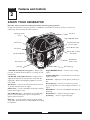 5
5
-
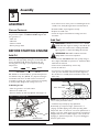 6
6
-
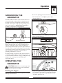 7
7
-
 8
8
-
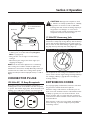 9
9
-
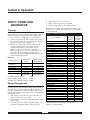 10
10
-
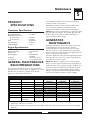 11
11
-
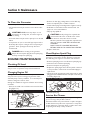 12
12
-
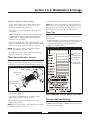 13
13
-
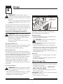 14
14
-
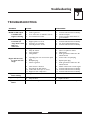 15
15
-
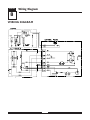 16
16
-
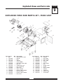 17
17
-
 18
18
-
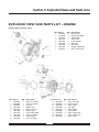 19
19
-
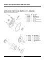 20
20
-
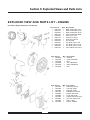 21
21
-
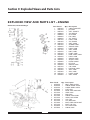 22
22
-
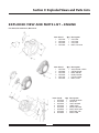 23
23
-
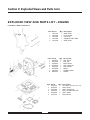 24
24
-
 25
25
-
 26
26
-
 27
27
-
 28
28
-
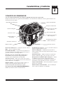 29
29
-
 30
30
-
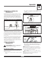 31
31
-
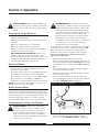 32
32
-
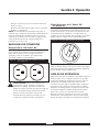 33
33
-
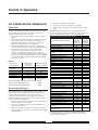 34
34
-
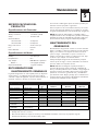 35
35
-
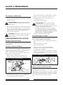 36
36
-
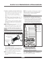 37
37
-
 38
38
-
 39
39
-
 40
40
-
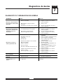 41
41
-
 42
42
-
 43
43
-
 44
44


Simplicity 01923-0 Manual de usuario
- Categoría
- Generadores de poder
- Tipo
- Manual de usuario
en otros idiomas
- English: Simplicity 01923-0 User manual
Artículos relacionados
-
Simplicity 01642-2 El manual del propietario
-
Troy-Bilt 01925-0 Manual de usuario
-
-
-
-
-
-
Briggs & Stratton PRO6500 Manual de usuario
-
-
Otros documentos
-
Snapper 1666-0 Manual de usuario
-
Generac Power Systems 5500EXL El manual del propietario
-
-
Troy-Bilt 01919-1 Manual de usuario
-
Troybilt 01923 El manual del propietario
-
DeVillbiss Air Power Company A04669 Manual de usuario
-
Toro Generator, T1800 Manual de usuario