FMI GA9200 Instrucciones de operación
- Categoría
- Chimeneas
- Tipo
- Instrucciones de operación

Save this manual for future reference.
For more information, visit www.fmiproducts.com
GA9200 SERIES
MANUAL ON/OFF SAFETY VALVE/PILOT KIT
For All Ramp Pan Burner
Natural and Propane/LP Gas Logs
WARNING: If the information in this manual is not
followed exactly, a re or explosion may result caus-
ing property damage, personal injury, or loss of life.
— Installation and service must be performed by
a qualied installer, service agency, or the gas
supplier.
WARNING: Improper installation, adjustment, al-
teration, service, or maintenance can cause injury or
property damage. Refer to this manual for correct in-
stallation and operational procedures. For assistance
or additional information consult a qualied installer,
service agency, or the gas supplier.
The GA9200 Series Manual On/Off Safety Valve/Pilot kit contains the following:
• PiezoIgnitor 097159-04
• ManualValve 901068-02
• PilotBurner(withnatural
gasorice) 901069-01
• PiezoIgnitorElectrode 901072-01
• SteelShroud-PilotKit 117106-01
• ControlDialInstructions 901042-01
• Brass3/8FLRx3/8MPTElbow 14264
• Brass3/8Fitting 14500
• PilotBracket 117107-01
• FlexConnector 101628-01
• 18"Propane/LPBrassOrice 104506-22
• 24"Propane/LPBrassOrice 104506-16
• 30"Propane/LPBrassOrice 104506-30
• Propane/LPPilotBurnerOrice901070-01
• Screw1/4"#8“B”pt(6ea.) 901075-01
• PilotValveControlDial 901079-01
• PilotValveDialExtension3" 901080-01
• PropaneConversionDecal 901691-01
• Brass3/8FLRx3/8FPTElbow 14528

www.fmiproducts.com
117422-01D2
MODEL DESCRIPTION Btu/Hr Input
Natural Gas
Btu/Hr Input
Propane/LP Gas
Minimum Vent
Opening
LSLR18 18"RampPan 60,000 50,000 8"(20.32)dia.
SMS18 18"RampPan 60,000 50,000 8"(20.32)dia.
BCS18 18"RampPan 60,000 50,000 8"(20.32)dia.
PHK18 18"RampPan 60,000 50,000 8"(20.32)dia.
LSLR24 24"RampPan 80,000 70,000 8"(20.32)dia.
SMS24 24"RampPan 80,000 70,000 8"(20.32)dia.
BCS24 24"RampPan 80,000 70,000 8"(20.32)dia.
PHK24 24"RampPan 80,000 70,000 8"(20.32)dia.
PHK30 30"RampPan 90,000 80,000 8"(20.32)dia.
BCS30 30"RampPan 90,000 80,000 8"(20.32)dia.
*Add6"ifsafetyvalve/pilotisused
**Atdepthindicated
FUEL INLET PRESSURE SPECIFICATIONS (W.C.)
Gas Min. Max.
NG 5.5"(14cm) 10.5"26.6cm
LP 11"(27.9cm) 13"(33cm
BURNER ORIFICE
NATURAL PROPANE/LP
LOG SIZE IN. NUM. IN. NUM.
LSLR18,SMS18,BCS18,PHK18 0.120 31 0.086 44
LSLR24,SMS24,BCS24,PHK24 0.140 28 0.099 39
PHK30,BCS30 0.150 25 0.106 36
INSTALLATION
MINIMUM FIREBOX SIZES
MODEL FRONT WIDTH* BACK WIDTH** DEPTH HEIGHT
LSLR18 28"(71.1cm) 18"(45.7cm) 16"(40.6cm) 18"(45.7cm)
SMS18 28"(71.1cm) 18"(45.7cm) 16"(40.6cm) 18"(45.7cm
BCS18 28"(71.1cm) 18"(45.7cm) 16"(40.6cm) 18"(45.7cm
PHK18 28"(71.1cm) 18"(45.7cm) 16"(40.6cm) 18"(45.7cm
LSLR24 32"(81.3cm 24"(61cm) 16"(40.6cm) 18"(45.7cm
SMS24 32"(81.3cm 24"(61cm) 16"(40.6cm) 18"(45.7cm
BCS24 36"(91.4cm) 23"(58.4cm) 16"(40.6cm) 18"(45.7cm
PHK24 36"(91.4cm) 23"(58.4cm) 16"(40.6cm) 18"(45.7cm
PHK30 42"(107cm) 29"(73.6cm) 18"(45.7cm 18"(45.7cm
BCS30 42"(107cm) 29"(73.6cm) 18"(45.7cm 18"(45.7cm
Figure 1 - Technical Information Charts

www.fmiproducts.com
117422-01D 3
CHECK GAS TYPE
YoumustinstallthisON/OFFSafetyValve/
PilotKitifyourgastypeispropane/LP.For
additionalconvenienceandsafety,thisON/
OFFSafetyValve/PilotKitcanbeusedwith
naturalgas.Thispilotkitcanonlybeinstalled
ontherightside(facing)ofthegaslogset.If
youareunsureoftheproperapplication,call
dealerwhereyouboughtlogset.
Ifthereplacedoesnothaveagassupply
shutoffvalve,onemustbeinstalled.
CONNECTING TO GAS SUPPLY
WARNING: This appliance
requires a 1/2" NPT (National
Pipe Thread) inlet connection to
the pressure regulator.
WARNING: A qualied ser-
vice person must connect log
set to gas supply. Follow all
local codes.
CAUTION: Never connect
propane/LP appliance directly
to the propane/LP supply. This
appliance requires an external
regulator (not supplied). Install
the external regulator between
the heater and propane/LP supply.
Installation Items Needed
Beforeinstallinglogset,makesureyouhave
theitemslistedbelow.
• piping(checklocalcodes)
• sealant(resistanttopropane/LPgas)
• equipmentshutoffvalve*
• testgaugeconnection*
• adjustable(crescent)wrenchorpliers
• sedimenttrap
• teejoint
• pipewrench
• exiblegasline
• 10mmDeepSocket
INSTALLATION
Continued
*Aequipmentshutoffvalve with 1/8" NPT
tapisanacceptablealternativetotestgauge
connection.Purchasetheoptionalequipment
shutoffvalvefromyourdealer.
For propane/LPunits, the installermust
supply an external regulator.The external
regulatorwillreduceincominggaspressure.
Youmust reduceincominggaspressureto
between11"and14"ofwater.Ifyoudonot
reduceincominggaspressure,heaterregula-
tordamagecouldoccur.Installexternalregu-
latorwiththeventpointingdownasshownin
Figure2.Pointingtheventdownprotectsit
fromfreezingrainorsleet.
WARNING: Never connect
natural gas appliance to private
(non-utility) gas wells. This
gas is commonly known as
wellhead gas.
CAUTION: Use only new,
black iron or steel pipe. Inter-
nally-tinned copper tubing may
be used in certain areas. Check
your local codes. Use pipe of
1/2" diameter or greater to allow
proper gas volume to log set. If
pipe is too small, undue loss of
volume will occur.
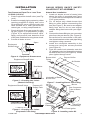
Figure 2 - External Regulator on
Propane/LP Supply Tank with Vent
Pointing Down
ExternalRegulator
VentPointingDown
Propane/LP
SupplyTank

www.fmiproducts.com
117422-01D4
Installationmustincludeanequipmentshut-
offvalve,union,andplugged1/8"NPTtap.
LocateNPTtapwithinreachfortestgauge
hookup.NPTtapmustbeupstreamfromlog
set(seeFigure3).
IMPORTANT:Installequipmentshutoffvalve
in an accessible location. The equipment
shutoff valve is for turning on or shutting off
thegastotheappliance.
Check your building codes for any special
requirementsforlocatingequipmentshutoff
valvetoappliance.
ApplypipejointsealantlightlytomaleNPT
threads.Thiswillpreventexcesssealantfrom
goingintopipe.Excesssealantinpipecould
resultinacloggedburnerorice.
WARNING: Use pipe joint
sealant that is resistant to liquid
petroleum (LP) gas.
INSTALLATION
Continued
Natural Gas
FromGasMeter
(5"W.C.**to10.5"
W.C.Pressure)
Propane/LP
FromExternal
Regulator
(11"W.C.**to14"
W.C.Pressure)
Figure 3 - Gas Connection
* Purchase the optional equipment shutoff
valvefromyourdealer.
**Minimuminletpressureforpurposeofinput
adjustment.
3"Minimum
SedimentTrap(Optionalfor
Propane/LPInstallation)
EquipmentShutoffValve*
ApprovedFlexibleGasHose
(ifallowedbylocalcodes)
Tee JointPipeNipple
Cap
Werecommend that you install a sediment
trapinsupplyline as shown in Figure 3.
Locatesedimenttrapwhereitiswithinreach
forcleaning.Installinpipingsystembetween
fuelsupplyandheater.Locatesedimenttrap
wheretrapped matter is notlikelyto freeze.
Asedimenttraptrapsmoistureandcontami-
nants.Thiskeepsthemfromgoingintologset
controls.Ifsedimenttrapisnotinstalledoris
installedwrong,logsetmaynotrunproperly.
CHECKING GAS CONNECTIONS
WARNING: Test all gas piping
and connections for leaks after
installing or servicing. Correct
all leaks at once.
WARNING: Never use an
open ame to check for a leak.
Apply a noncorrosive leak detec-
tion uid to all joints. Bubbles
forming show a leak. Correct all
leaks at once.
PRESSURE TESTING GAS SUPPLY
PIPING SYSTEM
Test Pressures In Excess Of 1/2 PSIG
(3.5 kPa)
1. Disconnectlogsetanditsindividualequip-
mentshutoffvalvefromgassupplypiping
system.
2. Capoffopenendofgaspipewhereequip-
mentshutoffvalvewasconnected.
3. Pressurizesupplypipingsystembyeither
openingpropane/LP supply tank valve
forpropane/LPgasoropeningmaingas
valve located on or near gas meter for
naturalgas,orusingcompressedair.
4. Checkalljointsofgassupplypipingsystem.
Applynoncorrosiveleakdetectionuidto
alljoints.Bubblesformingshowaleak.
5. Correctallleaksatonce.
6. Reconnectlogsetandequipmentshutoff
valvetogassupply.Checkreconnected
ttingsforleaks.

www.fmiproducts.com
117422-01D 5
Figure 4 - Equipment Shutoff Valve
Open
Closed
Equipment
Shutoff Valve
INSTALLATION
Continued
Figure 5 - Checking Gas Joints
(Natural Gas Only)
Gas Meter
EquipmentShutoffValve
Propane/LP
SupplyTank
EquipmentShutoffValve
Figure 6 - Checking Gas Joints
(Propane/LP Gas Only)
GA9200 SERIES ON/OFF SAFETY
VALVE/PILOT KIT ASSEMBLY
Natural Gas Installation
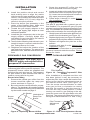
1. Locateairshutteratendofventuritube
wheretheoriceismounted(seeFigure
7).Loosenscrewandadjustairshutterto
3/16"openposition.
2. For18" burner only.Attach burner inlet
ttingtooricebeforereconnectingex
line(seeFigure7).Besuretouseadapter
tting from this kit, do not use original
adapterttingthatcamewithyourappli-
ance.
3. Connectthebrassttingtogasconnector
tubefromthepanburner(seeFigure8).
Becarefulnottocausekinksinthetube.
Usethreadsealantonthemalepipetting
andtightenusingawrench.
4. Installthe valve/pilot assembly to the
burnerpan using the screws provided
(seeFigure8).
5. Pushthecontrolrodextensionontothe
“D”shapedcontrolrodthroughthebottom
leftholeinthecover(seeFigure8).Install
piezoignitorthroughcover.
BurnerInlet
Fitting
Air Shutter
BurnerOrice
UndersideofRamp
BurnerPan
Figure 7 - Installing Burner Inlet Fitting
Figure 8 - Installing valve Kit
GasConnector
TubetoBrass
Fitting
Burner
Valve/Pilot
Assembly
ControlRod
Extension
PiezoIgnitor
Test Pressures Equal To or Less Than
1/2 PSIG (3.5 kPa)
1. Closeequipmentshutoffvalve(seeFig-
ure4).
2. Pressurizesupplypipingsystembyeither
opening propane/LPsupply tankvalve
forpropane/LPgasoropeningmaingas
valve located on or near gas meter for
naturalgas,orusingcompressedair.
3. Checkalljointsfromgasmeterfornatu-
ralgas(Figure5)orpropane/LPsupply
(Figure6)to equipment shutoffvalve.
Applynoncorrosiveleakdetectionuid
toalljoints.Bubblesformingshowaleak.
4. Correctallleaksatonce.

www.fmiproducts.com
117422-01D6
3. Screwthe propane/LP orice into the
burnermanifoldandsecuretightly.
4. Locateairshutterattheendoftheventuri
tubewhereoriceismounted(seeFigure
9).Loosenscrewandadjustairshutterto
fullyopen(maximum)position.
5. Followsteps1through11underNatural
Gas Installation,page5.
Changing Pilot Orice
Thepilotisprovidedwithanaturalgasori-
ceinstalled.Forpropane/LPgasyoumust
removeitandreplaceitwithanpropane/LPori-
ce.Thehardwarekitcontainsanpropane/LP
oricewitharedstripeforconvertingthepilot.
1. Gentlyloosenandremovethepilotlinecon-
nectionfromthebracket(seeFigure10).
2. Replacetheinjector(seeFigure10)withthe
propane/LPpilotinjectorwiththeredstripe.
3. Replaceandtightenthepilotlinetothe
bracket.
4. Continuewithstep3underNatural Gas
Installation, page5.
Note:Followtheinstructionsinyourhearth
kitowner’smanualunderthesection,Testing
Burner for Leaks.
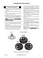
PILOT FLOW ADJUSTMENT
INSTALLATION
Continued
Figure 9 - Replacing Burner Orice
Figure 10 - Installing Propane/LP Pilot
Orice
O
F
F
P
I
L
O
T
O
N
PilotInjector
PilotFlow
Adjustment
Screw
Figure 11 - Pilot Flow Adjustment Screw
Afterinstallation is complete and the unit
hasbeen ignited, it maybenecessary to
adjustthepilot.Useasmallat-headscrew-
drivertoturntheowadjustmentscrewon
themanualcontrolvalve(seeFigure11).
Turn the screw counterclockwise to allow
moregas to ow or clockwise to restrict
gasow.Becarefultolimittheturnsto2
1/2fromthefully closedposition.Further
turningcanresultingasleakingatthead-
justmentscrewandthepilotamesizewill
diminish.Theproperpilotowwillresultina
strongblueamebetween1/2"and1"long.
6. Install the position decal and control
knob making sure to align the marks
withthecorrectstoppositionsofthegas
control.Pilotpositionwillallowtheknob
topushinabout1/2"(13mm).Alignthe
decalsinthepilotposition.
7. Place the burner pan assembly in the
center of the replace oor. Make sure
thefrontofthepanfacesforward.
8. Thread the gas supply adaptor tothe
replacegas supply pipe.Adjust to most
convenientposition.
9. Installthegasconnectortubetothegas
supply adaptor. Carefullyshape tube
andattachtogasinlettting.Becareful
nottocausekinksintube.
10.Testforleaksfollowinginstructionsinyour
hearthkitowner’smanualunderthesec-
tionTestingBurnerforLeaks.
11.Retightenandadjustthelocationofthe
gascontrolasnecessary.Thegascontrol
shouldbelevel,withthecontrolrodtothe
front.
PROPANE/LP GAS CONVERSION
WARNING: You must use a
ON/OFF safety valve/pilot kit for
propane/LP conversion.
To convert to propane/LPgas,the burner
oriceandpilotoricemustbereplaced.The
propane/LPburneroriceare supplied and
pre-sizedforeachsizelogset.Thepropane/
LPpilotorice isalso includedandcan be
usedtoconvertallsizelogsets.
Burner Inlet Fitting
1. Removethenaturalgasoricefromthe
burnermanifoldunderthe ramp pan
burnerasshowninFigure9.
2. Besuretousethecorrectoriceforyourap-
pliance.Thehardwarekitcontainsorices
foreachrespectivesizelogsetasindicated
bythemodelnumberonpage2.
Air Shutter
Undersideof
RampPan
Burner
Burner
Orice

www.fmiproducts.com
117422-01D 7
OPERATING APPLIANCE
OPERATING INSTRUCTIONS
FOR GA9200 SERIES
1.
STOP!Read the safetyinformation,in
theowner’smanualincludedwith your
hearthkit.
2. Makesureequipmentshutoffvalveisfully
open.
3. Pressinandturncontrolknobclockwise
to the OFFposition.
4. Waitve(5)minutestoclearoutanygas.
Thensmellfor gas around log set and
nearoor.Ifyousmellgas,STOP! See
SafetyinformationandAir For Combus-
tion and Ventilation, in your hearth kit
owner’smanual.Ifyoudon’t smellgas,
gotothenextstep.
5.
Turn control knob counterclockwise
to the PILOTpositionandpress
in.Keepcontrolknobpressedinforve
(5)seconds.
Note: You may be running this log set
for the rst time after hooking up to gas
supply. If so, control knob may need to be
pressed in for 30 seconds or more. This
will allow air to bleed from gas system.
6. Withcontrolknobpressedin,pushdown
andreleaseignitorbutton.Thiswilllight
pilot.Thepilotisattachedtotherearof
thefrontburner.Ifneeded,keeppressing
ignitorbuttonuntilpilotlights.
Note: If pilot does not stay lit, contact a
qualied service person or gas supplier
for repairs. Until repairs are made, light
pilot with match.
7. Keepcontrolknobpressedinfor30sec-
ondsafterlightingpilot.After30seconds,
releasecontrolknob.
Note: If pilot goes out, repeat steps 3
through 7.
Ifcontrolknobdoesnotpopupwhenre-
leased,contactaqualiedserviceperson
orgassupplierforrepairs.
8. Turncontrolknobcounterclockwise
to the ONposition.Burnershouldlight.
Ifburner does not light, call a qualied
serviceperson.
9. Toleavepilotlitandshutoffburnersonly,
turncontrolknobclockwise to the
PILOTposition.
Note: Follow the Troubleshooting section
in the owner’s manual included with your
hearth kit.
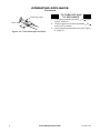
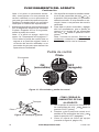
Ignitor
Pilot
FROM"PILOT"POSITION
SLIGHTPUSHTO
TURNOFF
PULLPUSH
TOLIGHT
ON
ON
FROM"PILOT"POSITION
SLIGHTPUSHTO
TURNOFF
PULLPUSH
TOLIGHT
FROM"PILOT"POSITION
SLIGHTPUSHTO
TURNOFF
PULLPUSH
TOLIGHT
ON OFF
On
Off
OFF
OFF
Figure 12 - Ignitor and Control Knob
Control Knob

www.fmiproducts.com
117422-01D8
Pilot
Thermocouple
Figure 13 - Thermocouple and Pilot
TO TURN OFF GAS
TO APPLIANCE
1. Turncontrolknobclockwise to the
PILOTposition.
2. Pressinandturncontrolclockwise
totheOFFposition.
3. Closeequipmentshutoffvalve(seeFigure
4,page5).
OPERATING APPLIANCE
Continued

www.fmiproducts.com
117422-01D 9
NOTES
_____________________________________________________
______________________________________________________
______________________________________________________
______________________________________________________
______________________________________________________
______________________________________________________
______________________________________________________
______________________________________________________
______________________________________________________
______________________________________________________
______________________________________________________
______________________________________________________
______________________________________________________
_____________________________________________________
______________________________________________________
______________________________________________________
______________________________________________________
______________________________________________________
______________________________________________________
______________________________________________________
______________________________________________________
______________________________________________________

117422-01
Rev.D
11/11
WARRANTY
KEEP THIS WARRANTY
FMI PRODUCTS, LLC LIMITED WARRANTIES
New Products
Standard Warranty:FMIPRODUCTS,LLCwarrantsthisnewproductandanypartsthereoftobefreefromdefects
inmaterialandworkmanshipforaperiodofone(1)yearfromthedateofrstpurchasefromanauthorizeddealer
providedtheproduct has been installed,maintained and operated inaccordancewith FMI PRODUCTS,LLC’s
warningsandinstructions.
Forproductspurchasedforcommercial,industrialorrentalusage,thiswarrantyislimitedto90daysfromthedate
ofrstpurchase.
Factory Reconditioned Products
Limited Warranty:FMIPRODUCTS,LLCwarrants factory reconditioned products and any parts thereof tobe
freefromdefectsinmaterialandworkmanshipfor30daysfromthedateofrstpurchasefromanauthorizeddealer
providedtheproduct has been installed,maintained and operated inaccordancewith FMI PRODUCTS,LLC’s
warningsandinstructions.
Terms Common to All Warranties
Thefollowingtermsapplytoalloftheabovewarranties:
Alwaysspecifymodelnumberandserialnumberwhencontactingthemanufacturer.Tomakeaclaimunderthis
warrantythebillofsaleorotherproofofpurchasemustbepresented.
Thiswarrantyisextendedonlytotheoriginalretailpurchaserwhenpurchasedfromanauthorizeddealer,andonly
wheninstalledbyaqualiedinstallerinaccordancewithalllocalcodesandinstructionsfurnishedwiththisproduct.
Thiswarrantycoversthecostofpart(s)requiredtorestorethisproducttoproperoperatingconditionandanallowance
forlaborwhenprovidedbyaFMIPRODUCTS,LLCAuthorizedServiceCenteroraproviderapprovedbyFMIPROD-
UCTS,LLC.Warrantypartsmustbeobtainedthroughauthorizeddealersofthisproductand/orFMIPRODUCTS,LLC
whowillprovideoriginalfactoryreplacementparts.Failuretouseoriginalfactoryreplacementpartsvoidsthiswarranty.
Travel,handling,transportation,diagnostic,material,laborandincidentalcostsassociatedwithwarrantyrepairs,unless
expresslycoveredbythiswarranty,arenotreimbursableunderthiswarrantyandaretheresponsibilityoftheowner.
Excludedfromthiswarrantyareproductsorpartsthatfailorbecomedamagedduetomisuse,accidents,improper
installation,lackofpropermaintenance,tampering,oralteration(s).
ThisisFMIPRODUCTS,LLC’sexclusivewarranty,andtothefullextentallowedbylaw;thisexpresswarrantyex-
cludesanyandallotherwarranties,expressorimplied,writtenorverbalandlimitsthedurationofanyandallimplied
warranties,includingwarrantiesofmerchantabilityandtnessforaparticularpurposetoone(1)yearonnewproducts
and30daysonfactoryreconditionedproductsfromthedateofrstpurchase.FMIPRODUCTS,LLCmakesno
otherwarrantiesregardingthisproduct.
FMIPRODUCTS,LLC’sliabilityislimitedtothepurchasepriceoftheproduct,andFMIPRODUCTS,LLCshallnot
beliableforanyotherdamageswhatsoeverunderanycircumstancesincludingindirect,incidental,orconsequential
damages.
Somestatesdonotallowlimitationsonhowlonganimpliedwarrantylastsortheexclusionorlimitationofincidental
orconsequentialdamages,sotheabovelimitationorexclusionmaynotapplytoyou.
Thiswarrantygivesyouspeciclegalrights,andyoumayalsohaveotherrightswhichvaryfromstatetostate.
Forinformationaboutthiswarrantycontact:
Model(
locatedonproductoridenticationtag
) _____________________________
SerialNo.(
locatedonproductoridenticationtag
) __________________________
DatePurchased __________________________
Keepreceiptforwarrantyverication.
2701S.HarborBlvd.
SantaAna,CA92704
1-866-328-4537
www.fmiproducts.com

Guarde este manual para referencias futuras.
Para obtener más información, visite www.fmiproducts.com
SERIE GA9200 PAQUETE DE PILOTO Y VÁLVULA DE CIERRE
DE SEGURIDAD MANUAL
Para todos los leños a gas natural y propano o gas LP en
quemadores con charola en forma de rampa
ADVERTENCIA: si no se sigue al pie de la letra la
información contenida en este manual, se puede pro-
ducir un incendio o una explosión que ocasione daños
a la propiedad, lesiones personales o la muerte.
— La instalación y el servicio deben ser realizados
por un instalador capacitado, agencia de servicio
o por el proveedor de gas.
ADVERTENCIA: la instalación, ajuste, alteración,
servicio o mantenimiento inadecuados pueden pro-
vocar lesiones o daños a la propiedad. Consulte este
manual para conocer los procedimientos correctos
de instalación y operación. Para obtener asistencia
o información adicionales consulte a un instalador
capacitado, agencia de servicio o al proveedor de gas.
ElpaquetedepilotoyválvuladecierredeseguridadmanualdelaserieGA9200contiene
lo siguiente:
• Encendedorpiezoeléctrico 097159-04
• Válvulamanual 901068-02
• Quemadordepiloto(con
orificioparagasnatural) 901069-01
• Electrodoparaencendido
piezoeléctrico 901072-01
• Armazóndeacero,paquetede
piloto 117106-01
• Instructivoparaelcuadrante
demando 901042-01
•
CodoMPT3/8FLRx3/8debronce
14264
•
Conexióndebronce
14500
•
Soportedelpiloto
117107-01
•
Conectorflexible
101628-01
• Orificiobroncede45.7cm(18")
parapropanoogasLP 104506-22
• Orificiodebroncede61cm(24")
parapropanoogasLP 104506-16
• Orificiodebroncede76.2cm(30")
parapropanoogasLP 104506-30
• Orificioparapilotodelquemador
parapropanoogasLP 901070-01
• Tornillode1/4"#8“B”pt(6) 901075-01
• Cuadrantedemandopara
válvuladepiloto 901079-01
• Extensiónde7.62cm(3")para
cuadrantedeválvuladepiloto 901080-01
•
Etiquetadeconversiónalpropano
901691-01
•
CodoFPT3/8FLRx3/8debronce
14528

www.fmiproducts.com
117422-01D12
*Añada15.2cm(6")sisevaautilizarválvulaypilotodeseguridad
**Alaprofundidadindicada
INSTALACIÓN
MODELO DESCRIPCIÓN Entrada (BTU/H)
Gas natural
Entrada (BTU/H)
Propano o gas LP
Abertura mínima
para ventilación
LSLR18
SMS18
BCS18
PHK18
Charolaenforma
derampade18''
60,000
60,000
60,000
60,000
50,000
50,000
50,000
50,000
20.32cm(8'')de
diámetro.
LSLR24
SMS24
BCS24
PHK24
Charolaenforma
derampade24''
80,000
80,000
80,000
80,000
70,000
70,000
70,000
70,000
20.32cm(8'')de
diámetro.
PHK30
BCS30
Charolaenforma
derampade30''
90,000
90,000
80,000
80,000
20.32cm(8'')de
diámetro.
ESPECIFICACIONES DE LA PRESIÓN DE ENTRADA DEL COMBUSTIBLE (C.A.)
Gas Mínimo Máximo
GN 14cm(5.5") 26.6cm(10.5")
LP 27.9cm(11") 33cm(13")
ORIFICO DEL QUEMADOR
NATURAL PROPANO O GAS LP
TAMAÑO DEL LEÑO PULG. NÚM. PULG. NÚM.
LSLR18,SMS18,BCS18,PHK18 0.120 31 0.086 44
LSLR24,SMS24,BCS24,PHK24 0.140 28 0.099 39
PHK30,BCS30 0.150 25 0.106 36
MEDIDAS MÍNIMAS DEL INTERIOR DE LA CHIMENEA
MODELO ANCHO PARTE
ANTERIOR*
ANCHO PARTE
POSTERIOR**
PROFUNDI-
DAD
ALTURA
LSLR18
SMS18
BCS18
PHK18
71.1cm(28")
71.1cm(28")
71.1cm(28")
71.1cm(28")
45.7cm(18")
45.7cm(18")
45.7cm(18")
45.7cm(18")
40.6cm(16")
40.6cm(16")
40.6cm(16")
40.6cm(16")
45.7cm(18")
45.7cm(18")
45.7cm(18")
45.7cm(18")
LSLR24
SMS24
BCS24
PHK24
81.3cm(32")
81.3cm(32")
91.4cm(36")
91.4cm(36")
61cm(24")
61cm(24")
58.4cm(23")
58.4cm(23")
40.6cm(16")
40.6cm(16")
40.6cm(16")
40.6cm(16")
45.7cm(18")
45.7cm(18")
45.7cm(18")
45.7cm(18")
PHK30
BCS30
107cm(42")
107cm(42")
73.6cm(29")
73.6cm(29")
45.7cm(18")
45.7cm(18")
45.7cm(18")
45.7cm(18")
Figura 1 - Tablas de información técnica

www.fmiproducts.com
117422-01D 13
*Unaválvuladecierredeequipoconrosca
tipoNPTde1/8"esunaalternativaaceptable
alaconexióndemedidordeprueba.Adquiera
laválvulaopcional de cierre de equipo del
distribuidor.
ParaunidadesdepropanoogasLP,elinsta-
ladordebe proveer un regulador externo. El
reguladorexternoreducirá lapresión delgas
entrante.Usteddebereducirlapresióndelgas
entrantedemaneraqueseadeentre11"y14"
deagua.Sinoreducelapresióndelgasentran-
te,sepuedenproducirdañosalreguladordel
calentador.Instaleelreguladorexternoconla
ventilaapuntandohaciaabajo,comosemuestra
enlafigura2.Siapuntalaventilahaciaabajose
protegedelalluviaheladaoaguanieve.
ADVERTENCIA: nunca co-
necte aparatos de gas natural a
un pozo de gas privado (que no
pertenezca al servicio público).
Este gas se conoce comúnmente
como gas de pozo.
PRECAUCIÓN: utilice única-
mente tubería nueva de hierro
negro o de acero. En ciertas
áreas, se puede usar tubería de
cobre con interior galvanizado.
Consulte los códigos locales.
Use tubería de 1/2" de diámetro o
mayor para permitir un volumen
apropiado para el juego de leños.
Si la tubería es demasiado an-
gosta, se producirá una pérdida
indebida de volumen.
VERIFIQUE EL TIPO DE GAS
SieltipodegasespropanooLPdebeinsta-
larestepaquetedepilotoyválvuladecierre
deseguridad.Para mayor conveniencia y
seguridad,estepaquetedepilotoyválvula
decierredeseguridadsepuedeutilizarcon
gasnatural.Estepaquetedepilotosedebe
instalarenelladoderecho(vistodefrente)del
juegodeleñosagas.Sinoestásegurosobre
laaplicacióncorrecta,llamealproveedorque
levendióeljuegodeleños.
Silachimeneanotieneválvulaparacerrar
laalimentacióndegas,debeinstalaruna.
CONEXIÓN AL SUMINISTRO DE GAS
ADVERTENCIA: este aparato
requiere una conexión de entra-
da tipo NPT (rosca de tubería
nacional) de 1/2" al regulador de
presión.
ADVERTENCIA: una perso-
na de servicio capacitada debe
conectar el juego de leños al
suministro de gas. Siga todos
los códigos locales.
PRECAUCIÓN: nunca co-
necte un aparato de propano
o gas LP directamente al sumi-
nistro. Este aparato requiere un
regulador externo (no incluido).
Instale el regulador externo entre
el calentador y el suministro de
propano o gas LP.
Elementos necesarios para la instalación
Antesdeinstalareljuegodeleños,asegúresede
tenerlosartículosqueseindicanacontinuación.
• Tubería(consulteloscódigoslocales),
• Sellador(resistentealpropanoogasLP),
• Válvuladecierredelequipo*,
• Conexióndemedidordeprueba*,
• Pinzasollaveajustable,
• Trampadesedimentos,
• UniónT,
• Llaveparatubería,
• Líneadegasflexible,
• Llavedecubode10mm.
INSTALACIÓN
Continuación
Figura 2 - Regulador externo en el
tanque de suministro de propano o gas
LP con la ventila orientada hacia abajo
Reguladorexterno
Ventila
apuntando
haciaabajo
Tanquede
suministro
depropanoo
gasLP

www.fmiproducts.com
117422-01D14
La instalación debe incluir una válvulade
cierrede equipo, launión y el conectorde
suministroconroscatipoNPTde1/8".Sitúe
laconexiónconroscatipoNPTasualcance
paralaconexióndelmedidordeprueba.La
conexióntipoNPTdebeestarantesdeljuego
deleños(consultelafigura3).
IMPORTANTE: instale laválvula de cierre
delequipoenunsitioaccesible.Laválvula
decierredelequipoesparaabrirocerrarel
suministrodegasalaparato.
Verifiquesiloscódigosdesuinmueblees-
tablecen requerimientos especiales para la
ubicación de válvulas de cierre del equipo
paraaparatos.
Aplique una pequeña cantidad de sellador
detuberíaen lasroscasNPTmacho. Esto
evitaráqueelexcesodeselladorentreala
tubería.Elexcesodeselladorenlatubería
puedeocasionarquelosorificiosdelquema-
dorsetapen.
ADVERTENCIA: use sellador
para tubería que sea resistente
al gas de petróleo líquido (LP).
INSTALACIÓN
Continuación
Gas naturaldesde
elmedidordegas
(presiónde5pulg.a
10.5pulg.deC.A.)
Propano o gas LP
desdeelregulador
externo(presiónde
11**a14pulg.de
C.A.)
Figura 3 - Conexión de gas
*Adquiera la válvula opcional de cierre de
equipoconsudistribuidor.
**Presióndeentradamínimaparapropósitos
deajustedeentrada.
Unmínimo
de7.62cm
(3pulg.)
Trampadesedimentos(opcionalparala
instalaciónconpropanoogasLP)
Válvuladecierrede
equipo*
Mangueraflexibleaprobadaparagas(en
casoqueloscódigoslocaleslapermitan)
UniónT
Conexióndetubo
Tapa
Se recomienda instalar una trampa de se-
dimentosenlalíneadesuministrocomose
muestra en la figura 3. Sitúe la trampa de
sedimentosdemaneraquesepuedatener
accesoaellaparalimpieza.Instálelaenel
sistemadelatuberíaentreelsuministrode
combustibleyelcalentador.Sitúelatrampa
desedimentosdondeseapocoprobableque
losmaterialesatrapadosenellasecongelen.
La trampa de sedimentos atrapa humedad
y contaminantes. Lo cual evita que estos
lleguenalos controles del juego de leños.
Silatrampadesedimentosnoseinstalao
seinstalaincorrectamente,esposiblequeel
juegodeleñosnofuncionecorrectamente.
REVISIÓN DE LAS CONEXIONES DE
GAS
ADVERTENCIA: pruebe
todas las tuberías de gas y sus
conexiones para saber si hay
fugas después de instalar o de
darle servicio. Repare todas las
fugas inmediatamente.
ADVERTENCIA: nunca use
una llama al descubierto en
busca de fugas. Aplique líquido
para detectar fugas no corrosivo
en todas las uniones. La forma-
ción de burbujas indicará una
fuga. Repare todas las fugas
inmediatamente.
PRUEBAS DE PRESIÓN DEL SISTEMA
DE TUBERÍA DE SUMINISTRO DE GAS
Pruebas de presión mayores a los 3.5
kPa (1/2 PSI)
1. Desconecteeljuegodeleñosysuválvula
decierrecorrespondientedelsistemade
tuberíadealimentacióndegas.
2. Coloqueunatapaenelextremoabierto
deltubodegasdondeestabaconectada
laválvuladecierredelequipo.
3. Regulelapresióndelsistemadetubería
de suministro abriendo la válvula del
tanquedesuministrodepropanoogas
LP,encasoqueutiliceestetipodegas,
o bien, abriendo la válvula principal de
gasqueselocalizaenelmedidordegas
natural o cerca de éste, ousandoaire
comprimido.
4. Revisetodaslasunionesdelsistemade
tubería de suministro de gas. Aplique
líquidoparadetectarfugasnocorrosivo
en todas las uniones. La formación de
burbujasindicaráunafuga.

www.fmiproducts.com
117422-01D 15
5. Reparetodaslasfugasinmediatamente.
6. Vuelvaaconectareljuegodeleñosyla
válvuladecierredelequipoalsuministro
degas. Revise las conexiones que se
volvieronaconectarencasodefugas.
Pruebas con presiones iguales o
menores a 3.5 kPa (1/2 PSI)
1. Cierrela válvulade cierre del equipo
(consultelafigura4).
2. Regulelapresióndelsistemadetubería
desuministroabriendolaválvuladeltan-
quedesuministrodepropanoogasLP,en
casoqueutiliceestetipodegas,obien,
abriendolaválvulaprincipaldegasque
selocalizaenelmedidordegasnaturalo
cercadeéste,ousandoairecomprimido.
3. Si tiene gas natural,reviselas uniones
desdeelmedidordegashastalaválvula
decierre(consultelafigura5)ysitiene
suministrodepropanoogasLP,desde
elsuministrohasta la válvula de cierre
(consultelafigura6).Apliquelíquidopara
detectarfugasnocorrosivoentodaslas
uniones.Laformacióndeburbujasindi-
caráunafuga.
4. Reparetodaslasfugasinmediatamente.
INSTALACIÓN
Continuación
Abierta
Cerrada
Válvulade
cierrede
equipo
Figura 5 - Revisión de las uniones de gas
(Para gas natural solamente)
Medidor
degas
Válvuladecierredeequipo
INSTALACIÓN DEL PAQUETE DE
PILOTO Y VÁLVULA DE CIERRE DE
SEGURIDAD SERIE GA9200
Instalación para gas natural
1. Sitúeelobturadordelairealfinaldeltubo
venturi,donde está montado el orificio
(consultelafigura7).Aflojeeltornilloy
ajusteelobturadordelaireabriéndoloa
unaposiciónde3/16".
2. Para modelos con quemador de 45.7
cm (18") solamente.Fijelaconexiónde
entradadelquemadoralorificioantesde
volveraconectarlalíneaflexible(consulte
lafigura7enlapágina16).Asegúrese
deutilizarlaconexióndeadaptaciónde
este paquete, no utilice la conexión de
adaptaciónquevieneconsuaparato.
3. Una la conexiónde bronce al tubo co-
nectordegasdelquemadorconcharola
(consulte la figura 8 en la página 16).
Tengacuidadodenoretorcereltubo.Apli-
queselladorpararoscasenlaconexión
machodeltuboyapriételaconunallave.
4. Instale elconjuntodeválvulaypilotoa
la charola del quemador utilizando los
tornillosincluidos(consultelafigura8en
lapágina16).
5. Introduzca laextensión de la varillade
controlenlavarilladecontrolenforma
de “D” a través del orificio ubicadoen
laparteinferiorizquierdadelacubierta
(vealafigura8enlapágina16).Instale
elencendedorpiezoeléctricoatravésde
lacubierta.
6. Pongalaetiquetaconlasposicionesyla
perilladecontrol,asegurándosequecada
marcacorrespondalaposicióncorrecta
delcontroldegas.Laposicióndelpiloto
permitirápresionarlaperillaalrededorde
13mm(1/2").Alineelasetiquetasenla
posiciónPILOT(piloto).
Tanquede
suministrode
propanoogasLP
Válvulade
cierrede
equipo
Figura 6 - Revisión de las uniones de gas
(Para propano o gas LP solamente)
Figura 4 - Válvula de cierre del equipo

www.fmiproducts.com
117422-01D16
INSTALACIÓN
Continuación
CONVERSIÓN A PROPANO O GAS LP
ADVERTENCIA: debe utilizar
un paquete de piloto y válvula
de cierre de seguridad para
conversión a propano o gas LP.
Para convertir a propano o gas LP, debe
reemplazarelorificiodelquemadoryelorificio
delpiloto.Seincluyenorificiosdelquemador
parapropano o gas LPy eltamaño está
preestablecido para cada juego de leños.
Tambiénseincluyeelorificiodepilotopara
propanoogasLP,elcualsepuedeutilizar
paraconvertirtodoslostamañosdejuegos
deleños.
Conexión de entrada del quemador
1. Quiteelorificioparagasnaturaldeltubo
múltiple del quemador ubicado debajo
delquemadorconlacharolaenformade
rampa,comosemuestraenlafigura9.
7. Pongaelconjuntodecharolayquemador
en el centro del piso de lachimenea.
Compruebeque el frente de la charola
estéorientadohaciaadelante.
8. Enrosque el adaptador desuministro
degasaltubodesuministrodegasde
lachimenea.Ajústeloalaposiciónmás
conveniente.
Figura 7 - Instalación de la conexión de
entrada del quemador
Figura 8 - Instalación del paquete de
válvula
Tuboconector
degasala
conexiónde
bronce
Quemador
Conjunto
deválvulay
piloto
Extensiónde
lavarillade
control
Encendedor
piezoeléctrico
Conexiónde
entradadel
quemador
Obturador
delaire
Oriciodelquemador
Fondodela
charola con
quemadoren
formaderampa
9. Instaleeltuboconectordegasaladap-
tadordesuministrodegas.Déformaal
tuboconcuidadoyúnaloalaconexión
deentradadegas.Tengacuidadodeno
retorcereltubo.
10.Revisesihayfugas,sigalasinstrucciones
delmanualdelpropietariodelachimenea
queaparecenenlasecciónCómodetec-
tarfugasenelquemador.
11.Vuelvaapretar y ajuste la ubicación
delcontrol de gas según se requiera.
Elcontrol de gas debe estar horizontal
conlavarilladecontrolorientadahacia
adelante.
Figura 9 - Cómo cambiar el oricio del
quemador
Obturador
delaire
Fondodela
charola con
quemadoren
formaderampa
Oriciodel
quemador
2. Asegúresedeutilizarelorificiodetamaño
correctoparaelaparato.Elpaquetede
ferreteríacontieneorificiospara cada
tamañodejuegodeleños,comoseindica
porelnúmerodemodeloenlapágina2.
3. Atornille el orificio para propano o gas
LPen el tubo múltipledel quemador y
apriételofirmemente.
4. Sitúeelobturadordelairealfinaldeltubo
venturi,donde está montado el orificio
(consultelafigura9).Aflojeeltornilloy
ajusteelobturadordelaireparaquese
abratotalmente(posiciónmáxima).
5. Realicelospasos1a14deInstalación
para gas natural,enlapágina5.

www.fmiproducts.com
117422-01D 17
INSTALACIÓN
Continuación
AJUSTE DE FLUJO DEL PILOTO
Unavezquehayaterminadolainstalacióny
encendidolaunidad,posiblementeseanece-
sarioajustarelpiloto.Conundesarmadorpla-
nopequeño,gireeltornillodeajusteprovisto
enlaválvuladecontrolmanual(consultela
figura11).Gireeltornilloensentidocontrario
aldelasmanecillasdelrelojparaaumentar
elflujoy,paradisminuirlo,gireeltornilloen
elsentidodelasmanecillasdelreloj.Tenga
cuidadodelimitarlasvueltasa21/2desdela
posiciónenlaqueelflujoestácompletamente
cerrado.Sigiraeltornillomásdeloindicado,
elgaspodríafugarsedeltornillodeajustey
la flama del piloto se haría más pequeña.
Elflujocorrectoalpilotoescuandolaflama
adquiereuncolorazulfuerteymidede1.3a
2.5cm(1/2"a1")delargo.
O
F
F
P
I
L
O
T
O
N
Inyectordelpiloto
Figura 10 - Instalación del orificio del
piloto para propano o gas LP
Cómo cambiar el orificio del piloto
Elpilotoseproporcionaconorificioparagas
natural instalado. Para propano o gas LP,
deberetirarloyreemplazarloporunorificio
parapropanoogasLP.Elpaquetedeferre-
teríacontieneunorificioparapropanoogas
LPconunafranjarojaparaconvertirelpiloto.
1. Concuidado,aflojeyquitelaconexión
delalíneadelpilotodelsoporte(con-
sultelafigura10).
2. Vuelvaacolocarelinyector(consultela
figura10)conelinyectordepilotopara
propanoogasLPconfranjaroja.
3. Reempláceloyaprietelalíneadelpiloto
enelsoporte.
4. Continúeconelpaso3delaInstalación
para gas natural en la página 15.
Nota: siga las instrucciones del manual del
propietariodelachimeneaqueaparecenenla
secciónCómo detectar fugas en el quemador.
Tornillopara
ajustarelflujo
delpiloto
Figura 11 - Tornillo para ajustar el flujo
del piloto
FUNCIONAMIENTO DEL
APARATO
INSTRUCCIONES DE
FUNCIONAMIENTO PARA
LA SERIE GA9200
1. ¡ALTO! Lealainformaciónsobreseguri-
dadcontenidaenelmanualdelpropieta-
rioproporcionadojuntoconlachimenea.
2. Asegúresedequelaválvuladecierredel
equipoestécompletamenteabierta.
3. Presioneygirelaperilladecontrolenel
sentidodelasmanecillasdelreloj
hastalaposiciónOFF(apagado).
4. Esperecinco(5)minutosaquesedisipe
elgas.Luego,acérqueseparaverificarsi
sepercibeoloragasalrededordeljuego
deleñoseinclusocercadelsuelo.Siper-
cibeoloragas,¡DETÉNGASE!Consulte
lainformacióndeSeguridad y Aire para
combustión y ventilación,provistaenel
manualdel propietario de la chimenea.
Sinopercibeoloragas,continúeconel
siguientepaso.
5. Girelaperilladecontrolensentidocon-
trarioaldelasmanecillasdelreloj
alaposiciónPILOT(piloto)ypresiónela.
Manténgalapresionadadurantecinco(5)
segundos.
Nota: posiblemente ésta sea la primera
vez que hace funcionar este juego de
leños después de conectarlo al suministro
de gas. Si es así, es posible que deba
presionar la perilla de control durante 30
segundos o más. Esto permitirá que el
aire salga del sistema de gas.
6. Continúepresionandolaperilladecon-
troly,almismotiempo,oprimaysuelte
elbotóndeencendido.Estoencenderá
elpiloto.El piloto está instalado en la
parteposteriordelquemadorfrontal.Si
esnecesario,continúepresionandoel
botóndelencendidohastaqueelpiloto
seencienda.

www.fmiproducts.com
117422-01D18
Encendedor
Figura 12 - Encendedor y perilla de control
Piloto
Termopar
Figura 13 - Termopar y piloto
CÓMO CERRAR EL
SUMINISTRO DE GAS
AL APARATO
1. Girelaperilladecontrolenelsentidode
lasmanecillas del reloj hasta la
posiciónPILOT(piloto).
2. Presioneygirelaperilladecontrolenel
sentidodelasmanecillasdelreloj
hastalaposiciónOFF(apagado).
3. Cierrela válvulade cierre del equipo
(consultelafigura4,página15).
Perilladecontrol
Piloto
DESDE LA POSICIÓN "PILOT"
(PILOTO) OPRIMA LIGERA-
MENTE PARA APAGAR, JALE Y
OPRIMA PARA ENCENDER
ON
(ENCENDIDO)
ON
(ENCENDIDO)
DESDE LA POSICIÓN "PILOT"
(PILOTO) OPRIMA LIGERA-
MENTE PARA APAGAR, JALE
Y OPRIMA PARA ENCENDER
DESDE LA POSICIÓN
"PILOT" (PILOTO) OPRIMA
LIGERAMENTE PARA
APAGAR, JALE Y OPRIMA
PARA ENCENDER
ON
(ENCENDIDO)
OFF
(APAGADO)
OFF
(apagado)
OFF
(APAGADO)
OFF
(APAGADO)
ON
(encendido)
Nota: si el piloto no permanece encen-
dido, comuníquese con una persona de
servicio calificado o con su proveedor de
gas para que realice las reparaciones ne-
cesarias. Encienda el piloto con un fósforo
hasta que se realicen las reparaciones.
7. Mantengalaperilladecontrolpresionada
por30segundosdespuésdeencender
elpiloto.Despuésdelos30segundos,
sueltelaperilladecontrol.
Nota: si el piloto se apaga, repita los
pasos 3 a 7 empezando en la página 17.
•Sialsoltarlaperilladecontroléstano
regresaasuposiciónoriginal,llamea
untécnicodeserviciocalicadooasu
proveedordegasparaquerealicenlas
reparacionesnecesarias.
FUNCIONAMIENTO DEL APARATO
Continuación
8. Girelaperilladecontrolensentidocontra-
rioaldelasmanecillasdelreloj a
laposiciónON(encendido).Elquemador
deberáencender.Sielquemadornoen-
ciende,llameaunapersonadeservicio
calificada.
9. Paradejarelpilotoencendidoyapagar
sólolos quemadores,gire la perilla de
control en el sentido de las manecillas
del reloj hasta la posición PILOT
(piloto).
Nota: consulte la sección Solución de
problemas contenida en el manual del
propietario provisto con la chimenea.

www.fmiproducts.com
117422-01D 19
NOTAS
_____________________________________________________
______________________________________________________
______________________________________________________
______________________________________________________
______________________________________________________
______________________________________________________
______________________________________________________
______________________________________________________
______________________________________________________
______________________________________________________
______________________________________________________
______________________________________________________
______________________________________________________
_____________________________________________________
______________________________________________________
______________________________________________________
______________________________________________________
______________________________________________________
______________________________________________________
______________________________________________________
______________________________________________________
______________________________________________________

117422-01
Rev.D
11/11
GARANTÍA
GUARDE ESTA GARANTÍA
GARANTÍAS LIMITADAS DE FMI PRODUCTS, LLC
Productos nuevos
Garantía estándar:FMIPRODUCTS,LLCgarantizaqueesteproductonuevoycualquieradesuspartesestaránlibres
dedefectosenmaterialesymanodeobraduranteunperiododeun(1)añoapartirdelafechadelacompraoriginal
deundistribuidorautorizado,siempreycuandoelproductohayasidoinstalado,mantenidoyoperadodeacuerdocon
lasadvertenciaseinstruccionesdeFMIPRODUCTS,LLC.
Paraproductosadquiridosdeusocomercial,industrialoparaalquiler,estagarantíaestálimitadaa90díasapartirde
lafechadelacompraoriginal.
Productos reacondicionados de fábrica
Garantía limitada:FMIPRODUCTS,LLCgarantizaesteproductoreacondicionadodefábricaycualquieradesuspartes
contracualquierdefectoenmaterialesymanodeobradurantelosprimeros30díasapartirdelafechadelacompra
conundistribuidorautorizado,siempreycuandoelproductosehayainstalado,mantenidoyoperadodeacuerdocon
lasadvertenciaseinstruccionesdeFMIPRODUCTS,LLC.
Términos comunes en todas las garantías
Lossiguientestérminosseaplicanatodaslasgarantíasmencionadasanteriormente:
Especifiquesiemprelosnúmerosdemodeloydeseriealcomunicarseconelfabricante.Parahacerunareclamaciónal
amparodeestagarantíasedeberápresentarlafacturauotrocomprobantedecompra.
Estagarantíaseextiendesóloalcompradorminoristaoriginalcuandoelproductoseadquiriódeundistribuidorautorizadoy
solamentesilainstalaciónlarealizauninstaladorcalificadoquesigalosrequisitosdeloscódigoslocalesylasinstrucciones
quesehanincluidoconesteproducto.
Estagarantíacubreelcostodelaspiezasnecesariaspararestauraresteproductoasuscondicionescorrectasdefun-
cionamientoyunacantidadcompensatoriaparalamanodeobracuandoseanproporcionadasporuncentrodeservicio
autorizadodeFMIPRODUCTS,LLCoundistribuidoraprobado.Laspiezasbajogarantíasedebenobtenerdedistribuidores
autorizadosparaesteproductoodeDESAHeating,LLC,quienproporcionarápiezasdereemplazooriginalesdefábrica.
Estagarantíaquedaanuladasinoseutilizanpiezasdereemplazooriginalesdefábrica.
Losgastosdeviaje,manejo,transporte,diagnóstico,materiales,manodeobraycostosindirectosrelacionadosconlas
reparacionesbajogarantíanosonreembolsablesbajoestagarantíaysonresponsabilidaddelpropietario,amenosque
esténexplícitamentecubiertosporestagarantía.
Estagarantíanocubrelosproductosopiezasquefallenoresultendañadosaconsecuenciadelusoincorrecto,accidentes,
instalaciónincorrecta,faltademantenimientoadecuado,manipulaciónoalteraciones.
ÉstaeslagarantíaexclusivadeFMIPRODUCTS,LLCy,paratodoslosefectoslegales,estagarantíaexplícitaexcluye
atodaslasdemásgarantías,explícitasoimplícitas,escritasoverbales,ylimitaladuracióndecualquieradelasgarantías
implícitas,inclusolasgarantíasdecomerciabilidadeidoneidadparaunusoparticular,alplazodeun(1)añoparaproductos
nuevosy30díasparaproductosreacondicionadosdefábrica,apartirdelafechadelacompraoriginal.FMIPRODUCTS,
LLCnoofreceningunaotragarantíarelacionadaconesteproducto.
LaresponsabilidaddeFMIPRODUCTS,LLCselimitaalpreciodecompradelproductoyFMIPRODUCTS,LLCnosehace
responsabledeningúnotrodañobajoningunacircunstancia,queincluyendañosindirectos,incidentalesyconsecuentes.
Algunosestadosnopermitenlaslimitacionesaladuracióndelasgarantíasimplícitasoalaexclusiónolimitaciónde
dañosincidentalesoconsecuentes,demodoqueesposiblequelalimitaciónoexclusiónanteriornoseapliqueausted.
Estagarantíaleotorgaderechoslegalesespecíficosyposiblementetengaotrosderechosquevaríandeunestadoaotro.
Paraobtenerinformaciónsobreestagarantía,comuníquesecon:
Modelo(localizadoenelproductooenlaetiquetadeidentificación) _________________________
Númerodeserie(localizadoenelproductooenlaetiquetadeidentificación) __________________
Fechadecompra ___________________________
Conservesureciboparalaverificacióndelagarantía.
2701S.HarborBlvd.
SantaAna,CA92704
1-866-328-4537
www.fmiproducts.com
-
 1
1
-
 2
2
-
 3
3
-
 4
4
-
 5
5
-
 6
6
-
 7
7
-
 8
8
-
 9
9
-
 10
10
-
 11
11
-
 12
12
-
 13
13
-
 14
14
-
 15
15
-
 16
16
-
 17
17
-
 18
18
-
 19
19
-
 20
20


FMI GA9200 Instrucciones de operación
- Categoría
- Chimeneas
- Tipo
- Instrucciones de operación
En otros idiomas
- English: FMI GA9200 Operating instructions