allen+roth SPK-200L Manual de usuario
- Categoría
- Chimeneas
- Tipo
- Manual de usuario

1
SAFETY PILOT CONVERSION KIT &
SAFETY PILOT CONVERSION KIT WITH REMOTE
80-10-620 -2022-04-27
AS22222
WARNING:
This conversion kit shall be installed by a qualied service agency in accordance with the manufac-
turer's instructions and all applicable codes and requirements of the authority having jurisdiction.
The information in these instructions must be followed to minimize the risk of re or explosion or to
prevent property damage, person injury or death. The qualied service agency performing this work
assumes responsibility for the proper conversion of this appliance with the kit.
ALLEN + ROTH™ and logo design are
trademarks or registered trademarks of
LF, LLC. All rights reserved.
Questions, problems, missing parts? Before returning to your retailer, call our customer
service department at 1-877-447-4768, 8:30 a.m. – 4:30 p.m., CST, Monday – Friday or
email us at [email protected].
ANSI Z21.60-2017 / CSA 2.26-2017 – “Decorative
gas appliances for installation in solid-fuel burning
replaces” ANSI Z21.84-2017 – “Manually lighted,
natural gas, decorative gas appliances for instal-
lation in solid-fuel burning appliances”
OMNI-Test Laboratories, Inc.
Tested &
Listed By
EM
Portland
Oregon USA
ITEM #4976285 / 4976276
Model #SPK-200L / SPK-300L
SPK300L
Remote LP/NG Safety Pilot Kit
SPK200L
Manual LP/NG Safety Pilot Kit
FOR USE WITH MODELS
VL-W18DL, VL-WO18D,
VL-W24DL, VL-WO24D,
VL-WO30D, VL-AA18D,
VL-AA24D, VL-AA30D,
VL-NO18D, VL-NO24D,
VL-NO30D, VL-SA18D,
VL-SA24D, VL-SA30D,
VL-CA18D, VL-CA24D,
VL-CA30D
INSTALLER: Leave this manual with the appliance.
CONSUMER: Retain this manual for future reference.

2
TABLE OF CONTENTS
Specications ................................................................................................................................... 3
Safety Information ............................................................................................................................ 3
Package Contents ............................................................................................................................6
Product Features ..............................................................................................................................7
Unpacking.........................................................................................................................................7
Preparing for Installation...................................................................................................................8
Installation ........................................................................................................................................ 9
Operation ........................................................................................................................................ 13
Troubleshooting ..............................................................................................................................17
Placement of Decals................................................................................................................18 - 19
Uninstallation & Conversion Back to Original ................................................................................. 20
Remote Control Operation.......................................................................................................21 - 27
Replacement Parts ..................................................................................................................28 - 29

3
Note: This vented appliance must be installed only in a solid-fuel burning replace with a working
ue and constructed of noncombustible material.
Solid fuels shall not be burned in a replace where a decorative appliance is installed.
The charts indicate technical information regarding the installation of your gas log set.
Please make sure that all of the specications shown are applicable before installation is attempted.
High Altitude Locations:
For high altitude installations in the United States, refer to the American Gas Association guidelines
for the gas designed appliance derating method. For elevations above 2,000 ft (610 m), input
ratings are to be reduced by 4% for each 1,000 ft (305 m) above sea level.
SPECIFICATIONS
GAS LOG SET MODEL
VL-WO18D, VL-AA18D
VL-NO18D, VL-SA18D
VL-CA18D, VL-W18DL
VL-WO24D, VL-AA24D
VL-NO24D, VL-SA24D
VL-CA24D, VL-W24DL
VL-WO30D, VL-AA30D
VL-NO30D, VL-SA30D
VL-CA30D
INPUT RATING (BTU/HR) 35,000 35,000 45,000 45,000 55,000 55,000
GAS TYPE LP NG LP NG LP NG
IGNITION TYPE PIEZO PIEZO PIEZO PIEZO PIEZO PIEZO
MAX. INLET PRESSURE (WC) 14” 10” 14” 10” 14” 10”
MIN. INLET PRESSURE (WC) 11” 7” 11” 7” 11” 7”
NORMAL PRESSURE (WC) 10” 5” 10” 5” 10” 5”
Input Rating
Gas Type
Ignition Type
Max. Inlet Pressure
Min. Inlet Pressure
Manifold Pressure
VL-WO24D
VL-AA24D
VL-NO24D
VL-WO30D
VL-AA30D
VL-NO30D
VL-WO18D
VL-AA18D
LP
Piezo Ignitor
14’’ WC
11’’ WC
10’’ WC
NG
Piezo Ignitor
7’’ WC
5.5’’ WC
7’’ WC
NG
Piezo Ignitor
7’’ WC
5.5’’ WC
7’’ WC
NG
Piezo Ignitor
7’’ WC
5.5’’ WC
7’’ WC
LP
Piezo Ignitor
14’’ WC
11’’ WC
10’’ WC
LP
Piezo Ignitor
14’’ WC
11’’ WC
10’’ WC
Model
35,000 BTU/hr 35,000 BTU/hr 45,000 BTU/hr 45,000 BTU/hr 55,000 BTU/hr 55,000 BTU/hr
After Safety Pilot Kit Installation
- Do not store or use gasoline or other ammable vapors and liquids in the vicinity of this or
any other appliance.
- WHAT TO DO IF YOU SMELL GAS
• Do not try to light any appliance.
• Do not touch any electrical switch; do not use any phone in your building.
• Immediately call your gas supplier from a neighbor’s phone. Follow the
gas supplier’s instructions.
• If you cannot reach your gas supplier, call the re department.
- Installation and service must be performed by a qualied installer, service agency or
the gas supplier.
WARNING: IF THE INFORMATION IN THIS MANUAL IS NOT FOLLOWED
EXACTLY, A FIRE OR EXPLOSION MAY RESULT CAUSING PROPERTY
DAMAGE, PERSONAL INJURY OR LOSS OF LIFE.
CAUTION - FOR YOUR SAFETY
SPECIFICATIONS
SAFETY INFORMATION

4
SAFETY INFORMATION
IMPORTANT: Read this owner’s manual carefully and completely before trying to assemble, operate,
or service this log set. Improper use of this log set can cause serious injury or death from burns, re,
explosion, electrical shock, and carbon monoxide poisoning.
Only a qualied installer, service agent, or local gas supplier may install and service this product.
WARNING: Do not store or use gasoline or other ammable vapors or liquids in the vicinity
of this or any other appliance.
WARNING: The log set is shipped from the factory adjusted for natural gas use only. Liquid
Propane can only be used after installation of Conversion Safety Pilot Kit.
CARBON MONOXIDE POISONING: Early signs of carbon monoxide poisoning resemble the u
with headaches, dizziness, or nausea. If you have these signs, the log set may not be working properly.
Get fresh air immediately! Have log set serviced. Some people are more affected by carbon monoxide
than others. These include pregnant women, people with heart or lung disease, people who are
anemic, those under the inuence of alcohol, and those living in high altitudes.
NATURAL AND PROPANE/LP GAS: Natural and Propane/LP gases are odorless. An odor-making
agent is added to the gas. The odor helps you detect a gas leak. However, the odor added to the
gas can fade. Gas may be present even though no odor exists. Make certain you read and under-
stand all warnings. Keep this manual for reference. It is your guide to operating this log set safely.
WARNING:
- Due to high temperatures, locate this appliance out of trafc and away from furniture
and draperies.
- Log set becomes very hot when operating. Keep children and adults away from hot
surfaces to avoid burns or clothing ignition. Log set will remain hot for a time after shut-
off. Allow surfaces to cool before touching.
- Carefully supervise young children when they are in the room with the log set.
- Do not place clothing or other ammable material on or near the appliance. Never place
any objects in the log set.
- Installation and repair should be done by a qualied service person. The appliance
should be inspected before use and at least annually by a professional service person.
More frequent cleaning may be required due to excessive lint from carpeting, bedding
material, etc. It is imperative that control compartments, burners and circulating air pas-
sageways of the appliance be kept clean.
- Any change to this log set or its controls can be dangerous.
- Do not use any accessories not approved for use with this log set.
- Keep the appliance area clear and free from combustible materials, gasoline, and other
ammable vapors and liquids.

5
SAFETY INFORMATION
1. This appliance is only for use with the type of gas indicated on the rating plate.
2.
Do not place propane/LP supply tank(s) inside any structure. Locate propane/LP supply tank(s) out-
doors.
3. If you smell gas
• Shut off gas supply.
• Do not try to light any appliance.
• Do not touch any electrical switch; do not use any phone in your building.
• Immediately call your gas supplier from a neighbor’s phone.
• Follow the gas supplier’s instructions.
• If you cannot reach your gas supplier, call the re department.
4. This log set shall not be installed in a bedroom or bathroom.
5. Do not use this log set as a wood-burning log set. Use only the logs provided with the log set.
6. Do not add extra logs or ornaments such as pine cones, vermiculite or rock wool. Using these
added items can cause sooting.
7. This log set is designed to be smokeless. If logs ever appear to smoke, turn off log set and call
a qualied service person. Note: During initial operation, slight smoking could occur due to log
curing and log set burning manufacturing residues.
8. To prevent the creation of soot, follow the instructions in Cleaning and Maintenance in your Vented
Log Set Owners Manual.
9. Before using furniture polish, wax, carpet cleaner or similar products, turn log set off. If heated,
the vapors from these products may create a white powder residue within burner box or on adja-
cent walls or furniture.
10. This log set needs fresh air ventilation to run properly.
11. Do not run log set
• Where ammable liquids or vapors are used or stored.
• Under dusty conditions.
12. Do not use this log set to cook food or burn paper or other objects.
13. Never place any objects in the replace or on the logs.
14. Do not use log set if any part has been under water. Immediately call a qualied service technician to
inspect the log set and to replace any part of the control system and any gas control which has
been under water.
15. Turn off and unplug log set and let cool before servicing. Only a qualied service person should
service and repair log set.
16. To prevent performance problems, do not use propane/LP fuel tank of less than 100 lb. capacity.
17. Provide adequate clearances around air openings.
Only a qualied agency should install and
replace gas piping, gas utilization equip-
ment or accessories, and repair and equip-
ment servicing. The term "qualied agency"
means any individual, rm, corporation, or
company that either in person or through a
representative is engaged in and is respon-
sible for:
a) Installing, testing, or replacing gas piping or
b) Connecting, installing, testing, repairing, or
servicing equipment; that is experienced in
such work; that is familiar with all precautions
required; and that has complied with all the re-
quirements of the authority having jurisdiction.
WARNING
This product and the fuels used to operate this product (liquid propane or natural gas), and the
products of combustion of such fuels, can expose you to chemicals including benzene, which is
known to the State of California to cause cancer and reproductive harm.
For more information go to www.p65Warnings.ca.gov
QUALIFIED INSTALLING AGENCY

6
PACKAGE CONTENTS
BURNER ORIFICE SIZES
Log Set
Size
Hole Diameter (mm)
SPK-200 SPK-300
LP NG LP NG
18" 1.78 2.58 1.8 2.55
24" 2.06 2.90 2.06 2.93
30" 2.26 3.25 2.28 3.3
SPK300L
Remote LP/NG Safety Pilot Kit
SPK200L
Manual LP/NG Safety Pilot Kit
SPK200L
Item Description
ABurner Pan Assembly
18", 24", or 30" (not included)
BLP Air Shutter
CBurner Orices (select
correct size and fuel Fig. a)
DThreaded Nipple (internal
threads for burner orice)
ERight Mount Decal
FLeft Mount Decal
G LP Pressure Regulator
HNG Air Shutter
IManual Control Valve
Assembly
J Nipple
KNG Pressure Regulator
5" WC
LFlare Fitting
M Pilot Assembly
NLP Pilot Orice
ONG Pilot Orice
P Flex Pilot Gas Line
SPK300L
Item Description
ARemote Transmitter
B Receiver
CHeat Shield
DRemote Control Valve
Assembly
ELP Air Shutter
FBurner Pan Assembly
18", 24", or 30" (not included)
G LP Pressure Regulator
HThreaded Nipple (internal
threads for burner orice)
ING Pressure Regulator
JNG Air Shutter
K Pilot Assembly Bracket
LFlex Pilot Gas Line
MBurner Orices (select
correct size and fuel Fig. a)
NLP Pilot Orice
ONG Pilot Orice
P Pilot Assembly
A
B
C
D
E
FG
L
K
J
I
H
M
NO
P
A
B
C
DE
G
H
I
M
L
J
K
N
O
P
F
LP18 = 18" Size & LP Fuel
LP24 = 24" Size & LP Fuel
LP30 = 30" Size & LP Fuel
NG18 = 18" Size & NG Fuel
NG24 = 24" Size & NG Fuel
NG30 = 30" Size & NG Fuel
Fig. a

7
PRODUCT FEATURES
UNPACKING
LIQUID PROPANE CONVERSION & SAFETY PILOT
This system requires no matches to light. You must use this optional system for Propane/LP
conversion.
The State of Massachusetts requires that the chimney ue damper, when used with decorative
gas log sets, be welded open or completely removed. In the State of Massachusetts, this
appliance must be installed by a licensed plumber or gastter.
In the State of Massachusetts the gas cock must be a T-handle type. The State of
Massachusetts requires that a exible appliance connector cannot exceed three feet
in length.
LOCAL CODES
Install and use log set with care. Follow all codes. In the absence of local codes, use the
latest edition of The National Fuel Gas Code, ANSI Z223.1, also known as NFPA 54*.
*Available from:
American National Standard Institute, Inc. National Fire Protection Association, Inc.
1430 Broadway 1 Batterymarch Park
New York, NY 10018 Quincy, MA 02269-9101
CAUTION: Do not remove the metal data plates from the burner pan. The data plates contain
important product information.
1. Remove logs, pan materials, and hardware from carton.
2. Remove all protective packaging applied to logs and base for shipment.
3. Check all items for any shipping damage. If damaged, promptly inform the dealer where you
bought the product.

8
This safety pilot system must be installed by a qualied profession service technician.
Before beginning assembly of product, make sure all parts are present. Compare parts with
package contents list. If any part is missing or damaged, do not attempt to assemble the
product. Contact customer service for replacement parts.
Estimated Assembly Time: 60 minutes
Tools Required for Assembly (not included): Philips Screwdriver, Gas Rated Pipe Sealant,
Adjustable Wrench Sediment Trap and Manual Shutoff Valve.
PREPARING FOR INSTALLATION

9
This safety pilot system must be installed by a qualied
profession service technician.
Note: Installation is easier when done outside of the
replace.
Save the orices removed from the appliance for future
use.
Conversion Safety Pilot Kit Assembly Instructions
1. Determine which side of the burner assembly the
control will be on – Left or Right and attach ON/OFF
Label to Valve Bracket.
-This assembly illustration shows the control on the
right side.
2. Remove Control Valve Assembly from carton and all
the other components.
3a. Remove the original ttings from the Burner Tube.
3b. Install either the LP or NG Air Shutter depending on
your fuel source.
Save the original ttings you removed in case you
return the unit to the standard design!
2.
3.
INSTALLATION
WARNING: Failure to position the
parts in accordance with these
diagrams or failure to use only parts
specically approved with this appli-
ance may result in property damage
or personal injury.
WARNING: It is mandatory you use the correct orice size and gas type for your installation.
Failure to do so will result in either a weak ame or an excessively large ame which could
cause overheating and result in property damage or injury.
LP Air Shutter
NG Air Shutter
Burner Tube
Burner Pan Assy.
SPK300L
Control Valve Assembly
SPK200L
Control Valve Assembly

10
4a. Install the Threaded Nipple
( and 90 degree tting- SPK300L)
to the Control Valve with the internal
threads facing opposite the Control Valve.
4b. Install the correct Burner Orice depending
on your Burner Pan size and fuel source.
5. Attach Control Valve Assy. to
the Air Shutter by rotating the entire
Control Valve Assy. clockwise. Make
sure Burner Orice is fully engaged
and the Control Valve Assy. is level
wit the Burner Pan.
6a. Attach the Pilot Bracket to the Burner Pan
with the 2 screws already attached to the
Burner Pan.
6b. Attach the Pilot Assembly to the Pilot Bracket
with 2 screws supplied.
6c. Install the correct LP or NG Pilot Orice
depending on your fuel source.
7a. Connect the Piezo Ignition Wire to the Piezo
Ignitor.
7b. Screw the Thermocouple Line into the Control
Valve.
7c. Attach the Flex Pilot Gas Line from the Pilot
Assembly to the Control Valve. Be careful to not
kink the line during assembly.
8a. Connect the correct Fuel Pressure Regulator and
install other tting necessary for your particular
installation.
INSTALLATION
90 Degree Fitting
SPK-300L Control
Valve Assy.
Threaded Nipple
LP18 = 18" Size & LP Fuel
LP24 = 24" Size & LP Fuel
LP30 = 30" Size & LP Fuel
NG18 = 18" Size & NG Fuel
NG24 = 24" Size & NG Fuel
NG30 = 30" Size & NG Fuel
Burner Orifice
Burner Orifice
(Internal Threads)
Burner Pan Assy.
Pilot
Brkt.
NG Pilot
Orifice
LP Pilot
Orifice
Pilot Assy.
4.
5.
6.
7.
SPK200L or SPK300L
Control Valve Assy. with
Orice Installed
SPK200L
Control Valve Assy.
4a.
4a.
4b.
4b.
LP18 = 18" Size & LP Fuel
LP24 = 24" Size & LP Fuel
LP30 = 30" Size & LP Fuel
NG18 = 18" Size & NG Fuel
NG24 = 24" Size & NG Fuel
NG30 = 30" Size & NG Fuel

11
CONNECTION TO GAS SUPPLY
WARNING: A qualied service person must
connect log set to gas supply. Follow all local
codes.
Installation Items Needed
Before installing log set, make sure you have
the items listed below.
• piping (check local codes)
• sealant (resistant to natural gas)
• equipment shutoff valve
• test gauge connection
• adjustable (crescent) wrench or pliers
• sediment trap
• tee joint
• pipe wrench
CAUTION: Only use a new, black iron or steel
pipe. Internally-tinned copper tubing may
be used in certain areas. Check your local codes.
Use pipe of 1/2" diameter or greater to allow
proper gas volume to log set. If pipe is too small,
loss of pressure will occur.
Installation must include an equipment shutoff
valve, union, and plugged 1/8" NPT tap.
Locate NPT tap within reach for test gauge
hook up. NPT tap must be upstream from log
set (see Figure 1).
IMPORTANT: Install equipment shutoff valve
in an accessible location. The equipment
shutoff valve is for turning on or shutting off
the gas to the appliance.
Apply pipe joint sealant lightly to male threads.
This will prevent excess sealant from going
into pipe. Excess sealant in pipe could result
in a clogged burner injector.
Install sediment trap in supply line. Locate sedi-
ment trap where it is within reach for cleaning.
Locate sediment trap where trapped matter is
not likely to freeze. A sediment trap traps
moisture and contaminants. This keeps them
from going into log set controls. If sediment trap
is not installed or is installed incorrectly, log set
may not run properly.
INSTALLATION

12
INSTALLATION
CHECKING GAS CONNECTIONS
WARNING: Test all gas piping and connections for leaks after installing or servicing. Correct all
leaks immediately.
WARNING: Never use an open ame to check for a leak. Apply a mixture of liquid soap and water
to all joints. If bubbles form, there may be a leak. Correct all leaks immediately.
Pressure Testing Gas Supply Piping System
Test Pressures In Excess Of 1/2 PSIG ( 3.5kPa )
1. Disconnect log set with its appliance main gas valve (control valve) and equipment shutoff valve
from gas supply piping system. Pressures in excess of 1/2 PSIG will damage log set regulator.
2. Cap off open end of gas pipe where equipment shutoff valve was connected.
3. Pressurize supply piping system by either using compressed air or opening gas supply tank valve.
4. Check all joints of gas supply piping system. Apply mixture of liquid soap and water to gas joints. If
bubbles form, there may be a leak.
5. Correct all leaks immediately.
6. Reconnect log set and equipment shutoff valve to gas supply. Check reconnected ttings for leaks.
Test Pressures Equal To or Less Than 1/2 PSIG (3.5 kPa)
1. Close equipment shutoff valve (See Fig. 2).
2. Pressure supply piping system by either using compressed air or opening gas supply tank valve.
3. Check all joints from gas meter to equipment shutoff valve (See Fig. 3 & 4). Apply mixture of liquid
soap and water to gas joints. If bubbles form, there may be a leak.
4. Correct all leaks immediately.
Pressure Testing Log set Gas Connections
1. Open equipment shutoff valve (See Fig. 2).
2. Open gas supply tank valve.
3. Make sure control knob of log set is in the
OFF position.
4. Check all joints from equipment shutoff valve to
control valve (See Fig. 3 & 4). Apply mixture of liquid
soap and water to gas joints. If bubbles form, there
may be a leak.
5. Light log set (see Operation, page 13). Check all other
internal joints for leaks.
6. Turn off log set (see "To Turn Off Gas to Appliance,"
page 14).
To convert the back to original gas rst make sure the equipment shutoff valve is closed (see Fig 2.).
Simply disconnect the LP conversion kit's "Air Nozzle" from the appliance with a wrench.
Fig. 2 - Equipment Shutoff Valve

13
OPERATION
FOR YOUR SAFETY
READ BEFORE LIGHTING
WARNING: If you do not follow these instructions exactly, a re or explosion may result
causing property damage, personal injury or loss of life.
A. This appliance has a pilot which must be lighted by the electronic ignitor. When lighting the pilot,
follow these instructions exactly.
B. BEFORE LIGHTING smell all around the appliance area for gas. Be sure to smell next to the oor
because some gas is heavier than air and will settle on the oor.
WHAT TO DO IF YOU SMELL GAS
• Do not try to light any appliance.
• Do not touch any electrical switch; do not use any phone in your building.
• Immediately call your gas supplier from a neighbor’s phone. Follow the gas supplier’s instructions.
• If you cannot reach your gas supplier, call the re department
C. Use only your hand to push in or turn the gas control knob. Never use tools. If the knob will not
push in or turn by hand, don’t try to repair it, call a qualied service technician. Forced or attempted
repair may result in re or explosion.
D. Do not use this appliance if any part has been under water. Immediately call a qualied service
technician to inspect the appliance and to replace any part of the control system and any gas control
which has been under water.
E. Solid fuels shall not be burned in a replace where a decorative appliance is installed.
F. A replace screen must be in place when the appliance is operating and, unless
other provisions for combustion air are provided, the screen shall have an opening(s) for introduction
of combustion air.
LIGHTING THE PILOT
1. STOP! Read the safety information as noted above.
WARNING: BE SURE THAT THE CHIMNEY DAMPER IS
FULLY OPEN.
IMPORTANT: Verify the input rating of the converted appliance with the
table on page 3.
2. Read all warnings and safety information in this manual
3. Locate the valve on the side of the unit, and push the gas control knob in
slightly (DO NOT FORCE) and turn clockwise to OFF (See Fig. 5).
4. Wait ve (5) minutes to clear out any gas. If you smell gas, STOP! Follow
the safety instructions above named "WHAT TO DO IF YOU SMELL GAS". If
you do not smell gas, continue onto the next step.
5. Slightly push in, and turn the control knob counterclockwise so the
white dot on the control knob lines up with "PILOT" (See Fig. 6). The pilot is
visible, at the back of the burner on the valve side. (See Fig. 6.5).
• Do not attempt to light the pilot by hand.
6. Push rmly and hold the control knob in fully and hold.
7. With control knob depressed, repeatedly push down the piezo ignitor
until the pilot lights.
LIGHTING INSTRUCTIONS
Fig. 5
SPK200L
Control Valve
Fig. 6
SPK300L
Control Valve

14
OPERATION
LIGHTING INSTRUCTIONS (Continued)
8. Keep control knob depressed for (30) seconds after pilot lights.
Release control knob.
• If the control knob does not pop up when released,
stop and immediately call a qualied service
technician or gas supplier.
• If pilot goes out repeat steps 3 through 7. Wait (1)
minute before attempting to light pilot again. If
after several tries the pilot still goes out, turn the
gas control knob clockwise to the "OFF".
position and call a qualied service technician.
LIGHTING THE BURNER
1. Ensure the pilot is lit. Turn the gas control knob counterclockwise
to the "ON" position (See Fig. 7)
WARNING: If the burner fails to light within 5 seconds, turn the control
knob clockwise to the "PILOT" position. Wait ve (5) minutes to clear out
any gas. If you smell any gas STOP! Follow the safety instructions on the
previous page named "WHAT TO DO IF YOU SMELL GAS." If you do not
smell gas, continue on to the next step.
WARNING: If after several tries the pilot still goes out, turn the gas
control knob clockwise to the "OFF" position and call a qualied service
technician.
1. Push in the control knob slightly and turn all the way clockwise , so the white dot is pointing to
the "OFF" position.
Note: Verify that the unit operates in accordance to these lighting instructions
TO TURN OFF GAS TO APPLIANCE
WARNING: Any glass doors shall be completely opened while appliance is in operation.
WARNING: The replace screen must be in place when the appliance is operating and,
unless other provisions for combustion are provided, the screen shall have an opening(s) for
introduction of combustion air.
Fig. 7
Fig. 6.5

15
OPERATION
INSPECTING BURNERS
Check pilot ame pattern daily when in use and at least yearly by a qualied service agency.
PILOT FLAME PATTERN
Fig. 8 shows a correct pilot ame pattern. Fig. 9 shows an incorrect pilot ame pattern. The incorrect
pilot ame is not touching the thermocouple. This will cause the thermocouple to cool, which shuts
the heater off. If pilot ame pattern is incorrect:
• turn heater off (see “To Turn Off Gas to Appliance” on page 14)
• see Troubleshooting pages 17.
Fig. 8 - Correct Pilot Flame Pattern Fig. 9 - Incorrect Pilot Flame Pattern
Normal Pilot Flame Thermocouple
LP Pilot Assembly
Thermocouple
Low/ Abnormal Pilot Flame
LP Pilot Assembly
WARNING: If yellow tipping occurs, your heater could produce increased levels of carbon
monoxide. If burner ame pattern shows yellow tipping, follow instructions at bottom of this
page.
WARNING: Do not allow fans to blow directly into the heater. Avoid any drafts that alter burner
ame patterns.
WARNING: Do not use a blower insert, heat exchanger insert or other accessory not approved for
use with this heater.
Notice: Do not mistake orange ames with yellow tipping. Dirt or other ne particles enter the heater
and burn causing brief patches of orange ame.

16
OPERATION
WARNING: Turn off log set and let cool before servicing.
CAUTION: You must keep control areas, burner, and circulating air passageways of log set
clean. Inspect these areas of log set before each use. Have log set inspected yearly by a
qualied service person. Log set may need more frequent cleaning due to excessive lint
from carpeting, bedding material, pet hair, etc.
WARNING: Failure to keep the primary air opening(s) of the burner(s) clean may result in sooting
and property damage.
BURNER ORIFICE HOLDER AND PILOT AIR INLET HOLE
The primary air inlet holes allow the proper amount of air to mix with the gas. This provides a clean
burning ame. Keep these holes clear of dust, dirt, lint and pet hair. Clean these air inlet holes prior to
each heating season. Blocked air holes will create soot. We recommend that you clean the unit every
three months during operation and have log set inspected yearly by a qualied service person.
We also recommend that you keep the burner tube and pilot assembly clean and free of dust and dirt.
To clean these parts we recommend using compressed air no greater than 30 PSI. Your local
computer store, hardware store or home center may carry compressed air in a can. If using
compressed air in a can, please follow the directions on the can. If you don’t follow directions on the
can, you could damage the pilot assembly.
Periodic examination and cleaning of the venting system and the solid fuel-burning replace, includ-
ing frequency of such examination and cleaning, must be done by a qualied agency.
BURNER FLAME PATTERN
Figure 10 shows a correct burner ame pattern. Figure 11 shows an incorrect burner ame pattern.
The incorrect burner ame pattern shows sporadic, irregular ame tipping. The ame should not be
dark or have an orange/reddish tinge.
Note: When using the log set the rst time, the ame will be orange for approximately one hour until
the log cures.
If burner ame pattern is incorrect, as shown in Figure 11.
• turn log set off (see To Turn Off Gas to Appliance, page 14).
• see Troubleshooting, page 17.
2-6 inches
above logs
6-12 inches
above logs
Fig. 10 - Correct/Normal Flame Pattern
with short ames
Fig. 11 -Incorrect/Abnormal Flame
Pattern with tall ames

17
TROUBLESHOOTING
PROBLEM POSSIBLE CAUSE CORRECTIVE ACTION
Pilot will not light 1. Obstruction in pilot gas-sup-
ply or pilot gas supply line is
kinked
2 . I n a d e q u a t e g a s s u p p l y
3. Air in line
1. Clear out obstruction. Replace pilot gas-
s u p p l y l i n e i f k i n k e d
2. Have gas pressure checked by installer
or gas installer
3. Let air clear; attempt to relight
Pilot will not stay lit
after releasing knob
1. Thermocouple connection to
valve is either too tight or too
loose
2. Bad thermocouple
1. Ensure thermocouple is nger tight and
t h e n 1 / 8 " t u r n w i t h a w r e n c h
2. Replace thermocouple
Log set extinguishes
a few minutes after
lighting
1. Inadequate gas supply
causes pilot ame to reduce
after burner lights
1. Using pilot adjustment, increase gas to
pilot. Pilot ame must be in contact with
the thermocouple tip
WARNING: If you smell gas:
• Shut off gas supply.
• Do not try to light any appliance.
• Do not touch any electrical switch; do not use any phone in your building.
• Immediately call your gas supplier from a neighbor’s phone. Follow the gas supplier’s instructions.
• If you cannot reach your gas supplier, call the re department.
IMPORTANT: Operating log set where impurities in air exist may create odors. Cleaning supplies, paint, paint
remover, cigarette smoke, cements and glues, new carpet or textiles, etc., create fumes. These fumes may mix
with combustion air and create odors.
WARNING: Turn off and let cool before servicing. Only a qualied service person should service
and repair log set.
Log set extinguishes
after burning for
some time (approxi-
mately 10 minutes
- 1 hour
1. Thermocouple has overheat-
e d ; g l a s s d o o r s a r e c l o s e d
2. Thermocouple has over-
heated; burner ames are
heating the thermocouple
cold junction
1. Be sure glass doors are open during
operation
2. Be sure the pilot assembly and the
ame diverter are in their proper posi-
tion. Re-arrange logs so the ame is not
deected to the thermocouple.

18
Model
Input Rating
Gas Type
Ignition Type
Max. Inlet Pressure
Min. Inlet Pressure
Normal Pressure
GLV024
45,000 BTU/hr
GLV030
55,000 BTU/hr
GLV018
35,000 BTU/hr
LP
Piezo Ignitor
14’’ WC
11’’ WC
11" WC
LP
Piezo Ignitor
14’’ WC
11’’ WC
11" WC
LP
Piezo Ignitor
14’’ WC
11’’ WC
11’’ WC
This appliance was converted on _____________________ (Day-Month-Year) to LP Gas
with Kit Model# by _____________________________________________________
(Name, Address of Company making this conversion), which accepts the responsibility that
this conversion has been properly made.
PLACING RATING TAG DECAL
0418GL009S
WARNING:
- Improper installation, adjustment, alteration, service, or maintenance can
cause property damage, personal injury, or loss of life. Refer to the owner's
manual provided with this heater. Installation and service must be performed
by a qualified installer, service agency, or the gas supplier.
- For installation in a solid-fuel burning fireplace only. The fireplace chimney
must have a permanent vent opening to atmosphere of not less than 50
square inches.
- A fireplace screen must be in place when the appliance is operating and,
unless other provisions for combustion air are provided, the screen shall
have an opening(s) for introduction of combustion air.
- Any glass doors shall be opened when the appliance is in operation.
Company Name
Street
City, State, ZIP
Serial Number:
Log Size
18’’ Vented
24’’ Vented
30’’ Vented
Height
19’’
19’’
20’’
Depth
15’’
15’’
15’’
Front Width
24’’*
30’’*
36’’*
Rear Width
20’’
26’’
32’’
Complies with ANSI Z21.84-2012, Standard
for Manually lighted, Natural Gas Decorative
Gas Appliances for Installation in Solid-Fuel
Burning Fireplaces.
Complies with ANSI Z21.60-2012, Standard
for Decorative Gas Appliances for Installa-
tion in Solid-Fuel Burning Fireplaces when
the LP Conversion Kit is installed by a
qualified technician.
Minimum Fireplace Size
*Important: If adding a Liquid Propane Conversion Safety Pilot Kit to the burner,
8" needs to be added to the front width dimension.
Model
Input Rating
Gas Type
Ignition Type
Max. Inlet Pressure
Min. Inlet Pressure
Normal Pressure
GLV024
45,000 BTU/hr
GLV030
55,000 BTU/hr
GLV018
35,000 BTU/hr
LP
Piezo Ignitor
14’’ WC
11’’ WC
11" WC
LP
Piezo Ignitor
14’’ WC
11’’ WC
11" WC
LP
Piezo Ignitor
14’’ WC
11’’ WC
11’’ WC
This appliance was converted on _____________________ (Day-Month-Year) to LP Gas
with Kit Model# by _____________________________________________________
(Name, Address of Company making this conversion), which accepts the responsibility that
this conversion has been properly made.
0418GL009S
WARNING:
- Improper installation, adjustment, alteration, service, or maintenance can
cause property damage, personal injury, or loss of life. Refer to the owner's
manual provided with this heater. Installation and service must be performed
by a qualified installer, service agency, or the gas supplier.
- For installation in a solid-fuel burning fireplace only. The fireplace chimney
must have a permanent vent opening to atmosphere of not less than 50
square inches.
- A fireplace screen must be in place when the appliance is operating and,
unless other provisions for combustion air are provided, the screen shall
have an opening(s) for introduction of combustion air.
- Any glass doors shall be opened when the appliance is in operation.
Serial Number:
Log Size
18’’ Vented
24’’ Vented
30’’ Vented
Height Depth Front Width Rear Width
Complies with ANSI Z21.84-2012, Standard
for Manually lighted, Natural Gas Decorative
Gas Appliances for Installation in Solid-Fuel
Burning Fireplaces.
Complies with ANSI Z21.60-2012, Standard
for Decorative Gas Appliances for Installa-
tion in Solid-Fuel Burning Fireplaces when
the LP Conversion Kit is installed by a
qualified technician.
Minimum Fireplace Size
*Important: If adding a Liquid Propane Conversion Safety Pilot Kit to the burner,
8" needs to be added to the front width dimension.
Company Name
Street
City, State, ZIP
WARNING: Information contained in the gures on this page may not be accurate or updated information.
DO NOT use any information inside of these gures for installation or technical purposes. They are only to be
used as a visual aid of how to place the decal.
After installing your new Kit #SPK-200L or SPK-300L you will need to update the
information that is included on your decorative/vented appliance by applying the included decal:
1. Locate the Rating Tag Decal in the Kit #SPK200L or SPK300L packaging (See Figure 0.1).
2. Locate the Rating Tag hanging from the vented appliance (See Figure 0.2).
3. Rating Tag Decal will go where the white box is (See Figure 0.3).
4. Peel off and stick the Rating Tag Decal so it looks like Figure 0.4.
5. Fill in date of conversion and name & address of company making the conversion on the
newly applied decal.
Fig 0.1
Fig 0.2 Fig 0.3 Fig 0.4
Model
Input Rating
Gas Type
Ignition Type
Max. Inlet Pressure
Min. Inlet Pressure
Normal Pressure
GLV024
45,000 BTU/hr
GLV030
55,000 BTU/hr
GLV018
35,000 BTU/hr
LP
Piezo Ignitor
14’’ WC
11’’ WC
11" WC
LP
Piezo Ignitor
14’’ WC
11’’ WC
11" WC
LP
Piezo Ignitor
14’’ WC
11’’ WC
11’’ WC
This appliance was converted on _____________________ (Day-Month-Year) to LP Gas
with Kit Model# by _____________________________________________________
(Name, Address of Company making this conversion), which accepts the responsibility that
this conversion has been properly made.
GAS LOG SET MODEL
VL-WO18D, VL-AA18D
VL-NO18D, VL-SA18D
VL-CA18D, VL-W18DL
VL-WO24D, VL-AA24D
VL-NO24D, VL-SA24D
VL-CA24D, VL-W24DL
VL-WO30D, VL-AA30D
VL-NO30D, VL-SA30D
VL-CA30D
INPUT RATING (BTU/HR) 35,000 35,000 45,000 45,000 55,000 55,000
GAS TYPE LP NG LP NG LP NG
IGNITION TYPE PIEZO PIEZO PIEZO PIEZO PIEZO PIEZO
MAX. INLET PRESSURE (WC) 14” 10” 14” 10” 14” 10”
MIN. INLET PRESSURE (WC) 11” 7” 11” 7” 11” 7”
NORMAL PRESSURE (WC) 10” 5” 10” 5” 10” 5”
2017, 2017, 2017,
2017, 2017, 2017,

19
PLACING LIGHTING TAG DECAL
1. STOP! Read the safety information on all the labels.
WARNING: BE SURE THAT THE CHIMNEY DAMPER IS FULLY OPEN.
2. Turn manual shutoff valve clockwise to the "OFF" position.
3. Wait five (5) minutes to clear out any gas. Then smell for gas, including near the floor.
If you smell gas, STOP! Follow "B" in the safety information above on this label. If you
don't smell gas, go to the next step.
4. Place a burning match on the surface of the burner embers. Do not hold match in hand.
5. Slowly turn manual gas shutoff valve ON. The gas should ignite in five (5) seconds. If
there is no ignition within ten seconds of laying the match down, set manual shutoff valve
to OFF and repeat steps 1-5 again.
TO TURN OFF GAS TO APPLIANCE
1. Gently press and turn the gas control knob in a clockwise direction to the
"FULL OFF" position.
FOR YOUR SAFETY
READ BEFORE LIGHTING
LIGHTING INSTRUCTIONS
VENTED GAS LOG SET
WARNING: If you do not follow these instructions exactly, a fire or explosion may result
causing property damage, personal injury or loss of life.
A. This appliance must be lighted by hand each time it is used. When lighting, follow
these instructions exactly.
B. BEFORE LIGHTING smell all around the appliance area for gas. Be sure to smell
next to the floor because some gas is heavier than air and will settle on the floor.
WHAT TO DO IF YOU SMELL GAS
• Do not try to light any appliance.
• Do not touch any electrical switch; do not use any phone in your building.
• Immediately call your gas supplier from a neighbor's phone. Follow the gas
supplier's instructions.
• If you cannot reach your gas supplier, call the fire department
C. Use only your hand to push in or turn the gas control knob. Never use tools. If the
knob will not push in or turn by hand, don't try to repair it, call a qualified service
technician. Forced or attempted repair may result in fire or explosion.
D. Do not use this appliance if any part has been under water. Immediately call a
qualified service technician to inspect the appliance and to replace any part of the
control system and any gas control which has been under water.
TO TURN OFF GAS TO APPLIANCE
LIGHTING INSTRUCTIONS
SAFETY PILOT KIT
IMPORTANT:
LOCATE HANGING TAGS ON THE APPLIANCE.
PEEL OFF AND PLACE OVER “LIGHTING INSTRUCTIONS” SECTION
OF THE SIMILAR HANGING TAG, BUT NOT OVER THE
“FOR YOUR SAFETY” SECTION.
REFERENCE PAGE 6 OF MANUAL
FOR FURTHER DETAILED INSTRUCTIONS.
1. STOP! Read the safety information as noted above.
WARNING: BE SURE THAT THE CHIMNEY DAMPER IS
FULLY OPEN.
2. Read all warnings and safety information in the manual
3. Locate the valve on the side of the unit, and push the gas control knob in
1. Push in the control knob slightly and turn all the way clockwise , so the white dot is
pointing to the "OFF" position.
slightly (DO NOT FORCE) and turn clockwise to OFF (See Fig. 5).
the safety instructions as noted above "WHAT TO DO IF YOU
SMELL GAS". If you do not smell gas, continue onto the next step.
5. Slightly push in, and turn the control knob counterclockwise so the
white dot on the control knob lines up with "PILOT" (See Fig. 6)
7. With control knob depressed, repeatedly push down the
4. Wait five (5) minutes to clear out any gas. If you smell gas, STOP! Follow
6. Push firmly and hold the control knob in fully and hold
piezo ignitor until the pilot lights.
The pilot is visible, at the back of the burner on the valve side (See Fig. 7).
• Do not attempt to light the pilot by hand.
Fig. 7
Fig. 5
Fig. 6
8. Keep control knob depressed for (30) seconds after pilot lights.
Release control knob.
• If the control knob does not pop up when released,stop and immediately
call a qualified service technician or gas supplier.
• If the pilot will not stay lit after several times, turn the gas control knob to
“OFF”, and call your service technician or gas supplier
9. Ensure the pilot is lit. Turn the gas control knob counterclockwise to
the "ON" position (See Fig. 8)
terclockwise to open or clockwise to close, as desired.
Fig. 8
WARNING: Information contained in the gures on this page may not be accurate or updated information.
DO NOT use any information inside of these gures for installation or technical purposes. They are only to be
used as a visual aid of how to place the decal.
After installing your new Kit #SPK200L or SPK300L, you will need to update the
information that is included on your decorative/vented appliance by applying the included decal:
1. Locate the Lighting Tag Decal in the Kit #SPK200L / SPK300L packaging (See Figure 0.5).
2. Locate the Lighting Tag hanging from the vented appliance (See Figure 0.6).
3. Lighting Tag Decal will go where the white box is (See Figure 0.7).
4. Peel off and stick the Lighting Tag Decal so it looks like Figure 0.8.
Fig 0.6 Fig 0.7 Fig 0.8
Fig 0.5

20
UNINSTALLATION & CONVERSION BACK TO ORIGINAL
UNINSTALLATION OF LIQUID PROPANE CONVERSION SAFETY PILOT KIT (See Figure 12)
1. Insure the gas is shut off at the main shut-off valve
2. Remove the pilot assembly by unscrewing the (2) screws holding the pilot to the pilot bracket.
a. Unscrew the pilot tube from the Safety Pilot Kit (SPK) valve.
b. Unscrew the thermocouple line from the SPK valve.
c. Remove the piezo wire from the piezo starter
3. Remove the SPK assembly by rotating the entire assembly counter clockwise
4. Remove the nozzle from the burner tube by turning counter clockwise.
CONVERTING BACK TO NG WITHOUT SAFETY PILOT KIT, FROM LP (See Figure 13)
1a. Thread the keyed shut-off valve to the replace gas
supply pipe. Use thread sealant.
1b. If a keyed shut-off valve is already installed, thread 1/2" female connector to the replace gas supply pipe.
Use thread sealant.
2. Thread adapter tting into keyed shut-off valve (or 1/2" Female Connector).
3. Install NG 3/8" orice tting onto the burner inlet tting using thread sealant on male threads of burner
inlet tting.
NOTE: This tting was supplied with the original Vented Gas Log model. If this is missing refer to the parts
list in the Vented Gas Log Owners Manual, and order a new part. DO NOT operate the appliance without the
correct orice tting (Item #80-06-034).
4. Install the gas ex tube to the adapter tting. Carefully shape tube to attach to orice tting.
Fig. 13Fig. 12
Step 3: NG 3/8" Orice Fitting
Step 2: Adapter tting
Step 2:
Step 2c:
Step 2b:
Step 2a:
Step 4:
Step 3:
Step 4: Flex Tube
Nozzel
SPK Assembly
Pilot Assembly Screws
Piezo Wire
Thermocouple Wire
Pilot Tube
Main Gas Connection
Turn Counterclockwise
or
Step 1a: Keyed shut-off valve
Step 1b: 1/2" Female Connector

21
REMOTE CONTROL OPERATION
Model SPK300L
1. STOP! Read the safety information on the pages before this.
2. Open the lower access panel located below the replace screen.
• Set receiver switch to “ON” position (See Fig. 17).
3. Turn control knob clockwise to the “OFF” position (See Fig. 17).
4. Wait ve (5) minutes to clear out any gas. Then smell for gas, including
near the oor. If you smell gas, STOP! Follow “B” in the safety information
on the pages before this. If you don’t smell gas, go to the next step.
5. Push in slightly and turn control knob counterclockwise to the
“PILOT” position (See Fig. 17). Depress control knob.
6. With control knob depressed, push down on the ignitor button until the
pilot lights. The pilot is located behind the replace screen, centered near
the rear of the burner (See Fig. 18).
7. Keep control knob depressed for (30) seconds after pilot lights. Release
control knob.
• If the control knob does not pop up when released, stop and immediately
call a qualied service technician or gas supplier.
• If pilot goes out repeat steps 3 through 7. Wait (1) minute before attempting
to light pilot again. If after several tries the pilot still goes out, turn the
gas control knob clockwise to the “OFF” position and call a qualied
service technician.
8. Turn control knob counterclockwise to the “ON” position.
9. To use the included thermostatic remote control, set receiver switch to
the “REMOTE” position (See Fig. 19). Press the ON button to turn on the
remote to ignite the main burner. Refer to the remote control instruction
manual on the next page for “MODE” and “SET” functions.
ONOFF REMOTE
LEARN
TO TURN OFF GAS TO APPLIANCE
Model SPK300L
1. Set thermostat (Transmitter) to the lowest setting.
2. Press the OFF button on the remote control.
3. Push in slightly and turn control knob clockwise to the “OFF” position.
Fig. 17 - Receiver
& Control Knob
Fig.19 - Remote
Fig. 18 - Pilot
Thermocouple
Low/ Abnormal Pilot Flame
LP Pilot Assembly
ON
OFF

22
TRANSMITTER
This remote control SYSTEM offers the user a battery-operated remote
control to power a latching solenoid such as those used with gas valves
used in some heater rated gas logs, gas replaces and other gas heating
appliances.
The solenoid circuit uses the battery power from the receiver to operate
a solenoid. The circuit has reversing polarity software which reverses
the positive (+) and negative (-) output of the receiver's battery power
to drive a latching solenoid ON/OFF. The SYSTEM is controlled by the
remote transmitter.
The transmitter operates on a (2) 1.5V AAA batteries. ALKALINE batter-
ies should always be used for longer battery life and maximum opera-
tional performance. Re-chargeable batteries should not be used.
Before using the transmitter, install the (2) AAA transmitter batteries into
the battery compartment. (Use caution that batteries are installed in the
proper direction)remote receiver's code must be matched to that of the
transmitter prior to initial use.
KEY SETTINGS
ON - Operates unit to on position, Manually operated solenoid ON.
OFF - Operates unit to off position, Manually operated solenoid OFF.
ON
OFF BUTTON
WALL CLIP SLOT
BATTERY
COMPARTMENT
FRONT BACK
OFF
ON BUTTON
ON
OFF
1
2
REMOTE CONTROL OPERATION
MULIT-FUNCTION WIRELESS REMOTE CONTROL SYSTEM FOR OPERATING
A LATCHING SOLENOID VALVE MANUALLY
INTRODUCTION
This remote control system was developed to provide a safe, reliable, and user-friendly remote control system
for gas heating appliances. The system is operated manually from the transmitter. The system operates on
radio frequencies (RF) within a 20-feet range using non-directional signals. The system operates on one of
1,048,576 security codes that are programmed into the transmitter at the factory; the remote receiver's code
must be matched to that of the transmitter prior to initial use.
IF YOU CANNOT READ OR UNDERSTAND THESE INSTALLATION IN-
STRUCTIONS DO NOT ATTEMPT TO INSTALL OR OPERATE
Review COMMUNICATION SAFETY under GENERAL INFORMATION section. This safety feature
shuts down the appliance when a potentially unsafe condition exists.

23
TEMP
TEMP
REMOTE CONTROL OPERATION
LCD - Liquid Crystal Display
1. DISPLAY Indicates CURRENT room temperature.
2. 0 F OR 0 C Indicates degrees Fahrenheit or Celsius.
3. FLAME Indicates burner/valve in operation.
4. TEMP Appears during manual operation.
SETTING ˚F / ˚C SCALE
The factory setting for temperature is ˚F. To change this setting
to ˚C, rst:
• Press the ON key and the OFF key on the transmitter at the
same time this will change from ˚F to ˚C. Follow this same
procedure to change from 0 C back to 0 F.
MANUAL FUNCTION
To operate the system in the manual “MODE” do the following.
ON OPERATION
Press the ON key the appliance ame will come on. During this
time the LCD screen will show ON, after 3 seconds the LCD
screen will default to display room temperature and the word
TEMP will show. (Flame icon wil appear on LCD screen in
manual on mode)
OFF OPERATION
Press the OFF key the appliance ame will shut off. During this
time the LCD screen will show OF, after 3 seconds the LCD
screen will default to display room temperature and the word
TEMP will show.
TEMP
1
2
3
4
TEMP
SCREEN WHILE
DEPRESSING ON
KEY
SCREEN WHILE
DEPRESSING OFF
KEY
SCREEN AFTER 3
SECOND DEFAULT
SCREEN AFTER 3
SECOND DEFAULT

24
REMOTE CONTROL OPERATION
The transmitter has ON and OFF manual functions that are activated by pressing either button on the face of
the transmitter. When a button on the transmitter is pressed the word ON or OF will appear on the LCD screen
to show while the signal is being sent. Upon initial use, there may be a delay of three seconds before the re-
mote receiver will respond to the transmitter. This is part of the system's design.
POWER SETTING – CON 1001 TH
The electronics in the remote control system have the capability of "powering" two different types of DC-pow-
ered components. If any operational problems are noted, contact Customer Service. The RECEIVER comes
from the factory programmed to provide pulse DC voltage (5.5 VDC to 6.3 VDC) to a latching solenoid.
REMOTE RECEIVER
The remote receiver (right) operates on (4) 1.5V AA-size
batteries. It is recommended that ALKALINE batteries be used
for longer battery life and maximum microprocessor performance.
IMPORTANT: New or fully charged batteries are essential to
proper operation of the remote receiver as a latching solenoid
power consumption is substantially higher than standard remote
control systems. Re-chargeable batteries should not be used.
NOTE: The remote receiver will only respond to the transmitter
when the 3-position slide button on the remote receiver is
in the REMOTE position. The remote receiver houses the
microprocessor that responds to commands from the transmitter
to control system operation.
IMPORTANT
THE REMOTE RECEIVER SHOULD BE POSITIONED WHERE AMBIENT
TEMPERATURES DO NOT EXCEED 130° F.
REMOTE
NO
FFO
LEARN
Requires 4-AA 1.5V
alkaline batteries
Learning
Button
Remote Receiver
Battery cover slides on/off
Slide
Switch
ON
REMOTE
OFF

25
REMOTE CONTROL OPERATION
FUNCTIONS:
• With the slide switch in the REMOTE position, the system will only
operate if the remote receiver receives commands from the trans-
mitter.
• Upon initial use or after an extended period of no use, the ON but-
ton may have to be pressed for up to three seconds before activat-
ing servo motor. If the system does not respond to the transmitter
on initial use, see LEARNING TRANSMITTER TO RECEIVER.
• With the slide switch in the ON position you can manually turn ON
the system.
• With the slide in the OFF position, the system is OFF.
• It is suggested that the slide switch be placed in the OFF position if
you will be away from your home for an extended period of time.
• Placing the slide switch in the OFF position also functions as a
safety "lock out" by both turning the system OFF and rendering the
transmitter inoperative.
INSTALLATION INSTRUCTIONS
INSTALLATION
The remote receiver can be mounted on or near the replace hearth. PROTECTION FROM EXTREME HEAT
IS VERY IMPORTANT. Like any piece of electronic equipment, the remote receiver should be kept away from
temperatures exceeding 130º F inside the receiver case. Battery life is also signicantly shortened if batteries
are exposed to high temperatures.
HEARTH MOUNT
The remote receiver can be placed on the replace hearth or
under the replace, behind the control access panel. Position
where the ambient temperature inside the receiver case does
not exceed 130º F. NOTE: Black Button is used on Hearth Mount
Applications.
WARNING
DO NOT CONNECT REMOTE RECEIVER DIRECTLY TO 110-120VAC POWER. THIS WILL BURN OUT
THE RECEIVER. FOLLOW INSTRUCTIONS FROM MANUFACTURER OF GAS VALVE FOR CORRECT
WIRING PROCEDURES. IMPROPER INSTALLATION OF ELECTRIC COMPONENTS CAN CAUSE
DAMAGE TO GAS VALVE AND REMOTE RECEIVER.
Wire terminals
Remote Receiver
REMOTE
OFF ON
LEARN
Reveiver
Slide
Button

26
REMOTE CONTROL OPERATION
WIRING INSTRUCTIONS
Make sure the remote receiver switch is in the OFF position. For
best results it is recommended that 18 gauge stranded wires
should be used to make connections and no longer than 20-feet.
This remote receiver is to be connected to a manual valve with a
latching ON/OFF solenoid.
Connect two 18 gauge stranded or solid wires from the remote
receiver terminals to the latching solenoid. (See gure to the right)
IMPORTANT NOTE: Operation of this control is dependent on
which wire is attached to which terminal. If operation of control
does not correspond to operating buttons on transmitter, reverse
wire installation at the receiver or at the control. NOTE: Up to 6.3
VDC of power is provided at the receiver terminal.
GENERAL INFORMATION
COMMUNICATION – SAFETY – TRANSMITTER – (C/S – TX)
This remote control has a COMMUNICATION –SAFETY function built into its software. It provides an extra
margin of safety when the TRANSMITTER is out of the normal 20-foot operating range of the receiver.
The COMMUNICATION – SAFETY feature operates in the following manner, in all OPERATING MODES –
ON/ ON THERMO.
At all times and in all OPERATING MODES, the transmitter sends an RF signal every fteen (15) minutes, to
the receiver, indicating that the transmitter is within the normal operating range of 20-feet. Should the receiver
NOT receive a transmitter signal every 15 minutes, the IC software, in the RECEIVER, will begin a 2-HOUR
(120-minute) countdown timing function. If during this 2-hour period, the receiver does not receive a signal
from the transmitter, the receiver will shut down the appliance being controlled by the receiver. The RECEIVER
will then emit a series of rapid “beeps” for a period of 10 seconds. Then after 10 seconds of rapid beeping,
the RECEIVER will continue to emit a single “beep” every 4 seconds until a transmitter ON or MODE Button
is pressed to reset the receiver. The intermittent 4-second beeping will go on for as long as the receiver’s
batteries last which could be in excess of one year.
To “reset” the RECEIVER and operate the appliance, you must press the ON button on the transmitter. By
turning the system to ON, the COMMUNICATION -SAFETY operation is overridden and the system will return
to normal operation. The COMMUNICATION – SAFETY feature will reactivate should the transmitter be taken
out of the normal operating range or should the transmitter’s batteries fail or be removed.
Wire terminals
Remote Receiver
REMOTE
OFF ON
LEARN
Reveiver
Slide
Button
Reveiver
Slide
Button
REMOTE
OFF
PULSE MODE
Terminals
LEARN
ON
Remote Receiver
Black Wire
Red Wire
WirePulse Connection
Concentric Valve

27
REMOTE CONTROL OPERATION
LEARNING TRANSMITTER TO RECEIVER
Each transmitter uses a unique security code. It will be necessary to press the LEARN button on the receiver
to accept the transmitter security code upon initial use, if batteries are replaced, or if a replacement transmitter
is purchased from your dealer or the factory. In order for the receiver to accept the transmitter security code,
be sure the slide button on the receiver is in the REMOTE position; the receiver will not LEARN if the slide
switch is in the ON or OFF position. The LEARN button in located on the front face of the receiver; inside the
small hole labeled LEARN. Using a small screwdriver or end of a paperclip gently press and release the black
LEARN button inside the hole. When you release the LEARN button the receiver will emit an audible “beep”.
After the receiver emits the beep press the transmitter ANY button and release. The receiver will emit several
beeps indicating that the transmitter’s code has been accepted into the receiver.
The microprocessor that controls the security code matching procedure is controlled by a timing function. If you
are unsuccessful in matching the security code on the rst attempt, wait 1 - 2 minutes before trying again--this
delay allows the microprocessor to reset its timer circuitry--and try up to two or three more times.
BATTERY LIFE
Replace all batteries regularly. When the transmitter no longer operates the remote receiver from a distance
it did previously (i.e., the transmitter's range has decreased) or the remote receiver does not function at all,
the batteries should be checked. It is important that the remote receiver batteries are fully charged, providing
combined output voltage of at least 5.5volts. The hand held transmitter should operate with as little as 2.5 volts
battery power.
TROUBLE SHOOTING
Life expectancy of the alkaline batteries can be up to 12 months depending on use of the solenoid function.
If you encounter problems with your replace system, the problem may be the replace itself or it could be
with the CON1001-TH remote system. Review the replace manufacturer's operation manual to make sure all
connections are properly made. Then check the operation of the remote in the following manner:
• Make sure the batteries are correctly installed in the RECEIVER. One reversed battery will keep receiver
from operating properly.
• Check battery in TRANSMITTER to ensure contacts are touching (+) and (-) ends of battery. Bend metal
contacts in for tighter t.
• Be sure RECEIVER and TRANSMITTER is within 20-feet operating range.
• Clear Codes: Memory in the receiver might be full if the learn button is pressed too many times. If this
happens it will not allow any more codes to be learned and no audible beep will be heard. To clear memory,
place the receiver slide switch into the REMOTE position. Press the learn button and release after 10
seconds. You should hear three (3) long audible beeps indicating all codes have cleared. You can now
“learn” the transmitter to the receiver as described in the General Information Section.
• Keep RECEIVER from temperatures exceeding 130° F. Battery life shortened when ambient temperatures
are above 115° F.
• If RECEIVER is installed in tightly enclosed metal surround, the operating distance will be shortened.
• Rechargeable batteries should not be used. They do not supply sufcient power to operate the remote
system.
SPECIFICATIONS BATTERIES:
Transmitter (2) 1.5 volt AAA t bateries Remote Receiver 6V - 4 ea. AA 1.5 Alkaline
FCC REQUIREMENTS NOTE: THE MANUFACTURER IS NOT RESPONSIBLE FOR ANY RADIO OR TV
INTERFERENCE CAUSED BY UNAUTHORIZED MODIFICATIONS TO THIS EQUIPMENT. SUCH MODI-
FICATIONS COULD VOID THE USER’S AUTHORITY TO OPERATE THE EQUIPMENT.

28
REPLACEMENT PARTS
For replacement parts, call our Technical Service Department at 1-877-447-4768, 8:30 a.m. –4:30 p.m.,
CST, Monday – Friday.
SPK200L
Manual LP/NG Safety Pilot Kit
4
15.2
15.1
17.2
17.1
18
16.1
16.2
9,10,11,12,13,14
19
1
2
3
6
5
7
8
SPK200L
ITEM NO. DESCRIPTION QTY PART NO.
1 Control Knob GZ37-11 1 80-05-122
2 Piezo Ignitor GZ37-09 1 80-05-121
3 Control Valve Nut GS2A-11 1 80-05-114
4 Heat Shield Bracket GZ34-02 1 80-05-116
5 Piezo Nut GZ34-09A 1 80-05-117
6 Brass Fitting, 3/8” NPT x 3/8” Flare -GZ34-13 1 80-05-119
7Control Valve GZ-26 1 80-05-115
8 Nipple GZ37-04 1 80-05-120
9 Orice, 18” LP SPK200LP-18 1 80-05-128
10 Orice, 24” LP SPK200LP-24 1 80-05-129
11 Orice, 30” LP SPK200LP-30 1 80-05-130
12 Orice, 18” NG SPK200N-18 1 80-05-131
13 Orice, 24” NG SPK200N-24 1 80-05-132
14 Orice, 30” NG SPK200N-30 1 80-05-133
15.1 Pressure Regulator, LP GR-130A 1 80-05-113
15.2 Pressure Regulator, NG GR-130 1 80-05-112
16.1 Air Shutter, LP SPK300-07 1 80-05-134
16.2 Air Shutter, NG SPK300N-02 1 80-05-135
1 7. 1 Pilot Orice, LP GZ37-15LP 1 80-05-125
1 7. 2 Pilot Orice, NG GZ37-15NG 1 80-05-126
18 Pilot Assembly GZ34-12 1 80-05-118
19 Flex Pilot Line GZ37-16 1 80-05-127

29
REPLACEMENT PARTS
For replacement parts, call our Technical Service Department at 1-877-447-4768, 8:30 a.m. –4:30 p.m.,
CST, Monday – Friday.
SPK-300L
Remote LP/NG Safety Pilot Kit
7,8,9,10,11,12
13.1
17
1
3
5
16
6
2
4
13.2
14.2
14.1
15.1
15.2
SPK-300L
ITEM NO. DESCRIPTION QTY PART NO.
1Control Assembly GH03-3 180-05-108
2 Piezo Ignitor GZ37-09 1 80-05-121
3Receiver Assy GH03-R 180-05-110
4 Receiver Heat Shield GH03-HS 1 80-05-109
5 non-Thermostatic Transmitter (Remote Control) GH03-D 1 80-05-111
6 Brass Fitting, 3/8” NPT x 3/8” FlarE GZ37-13 1 80-05-124
7 Orice, 18” LP SPK200LP-18 1 80-05-128
8 Orice, 24” LP SPK200LP-24 1 80-05-129
9 Orice, 30” LP SPK200LP-30 1 80-05-130
10 Orice, 18” NG SPK200N-18 1 80-05-131
11 Orice, 24” NG SPK200N-24 1 80-05-132
12 Orice, 30” NG SPK200N-30 1 80-05-133
13.1 Air Shutter LP SPK300-07 1 80-05-134
13.2 Air Shutter NG SPK300N-02 1 80-05-135
14.1 Pressure Regulator, LP GR-130A 1 80-05-113
14.2 Pressure Regulator, NG GR-130 1 80-05-112
15.1 Pilot Orice, LP GZ37-15LP 1 80-05-125
15.2 Pilot Orice, NG GZ37-15NG 1 80-05-126
16 Pilot Assembly GZ37-12 180-05-123
17 Flex Pilot Line GZ37-16 1 80-05-127
Printed in China

30
OMNI-Test Laboratories, Inc.
EM
KIT DE CONVERSIÓN DE PILOTO DE
SEGURIDAD Y KIT DE CONVERSIÓN DE
PILOTO DE SEGURIDAD CON
CONTROL REMOTO
ADVERTENCIA:
La instalación de este kit de conversión debe estar a cargo de una agencia de servicio calicada
de acuerdo con las instrucciones del fabricante y todos los códigos y requisitos aplicables de la
autoridad competente.
Se debe seguir la información de estas instrucciones para minimizar el riesgo de incendio o ex-
plosión o para evitar daños materiales, lesiones personales o la muerte. La agencia de servicio
calicada que realiza este trabajo asume la responsabilidad de la conversión adecuada de este
electrodoméstico con el kit.
ALLEN + ROTH™ y el diseño del logotipo
son marcas comerciales o marcas registradas
de LF, LLC. Todos los derechos reservados.
ANSI Z21.60-2017 / CSA 2.26-2017 – "Aparatos
de gas decorativos para instalar en chimeneas
que queman combustible sólido" ANSI Z21.84-
2017- "Aparatos de gas decorativos, a gas
natural, encendidos manualmente para instalar
en aparatos que queman combustible sólido"
Probado y
homologado por
Portland,
Oregon, EE. UU.
ARTÍCULO #4976285 / 4976276
MODELO #SPK-200L / SPK-300L
SPK300L
Kit de piloto de seguridad manual PL/GN con control remoto
SPK200L
Kit de piloto de seguridad manual PL/GN
PARA USAR CON LOS MODELOS.
VL-W18DL, VL-WO18D,
VL-W24DL, VL-WO24D,
VL-WO30D, VL-AA18D,
VL-AA24D, VL-AA30D,
VL-NO18D, VL-NO24D,
VL-NO30D, VL-SA18D,
VL-SA24D, VL-SA30D,
VL-CA18D, VL-CA24D,
VL-CA30D
INSTALADOR: deje este manual junto al electrodoméstico.
CONSUMIDOR: conserve este manual para referencia futura.
¿Preguntas, problemas, piezas faltantes? Antes de volver a la tienda, llame a nuestro
Departamento de Servicio al Cliente al 1-877-447-4768, de lunes a viernes de 8:30 a.m. a 4:30 p.m.,
hora central estándar, o envíenos un correo electrónico a [email protected].
80-10-620 -2022-04-27

31
ÍNDICE
Especicaciones ............................................................................................................................. 32
Información de seguridad ...............................................................................................................32
Contenido del paquete ................................................................................................................... 35
Características del producto ........................................................................................................... 36
Desembalaje...................................................................................................................................36
Preparación para la instalación ...................................................................................................... 37
Instalación ...................................................................................................................................... 38
Funcionamiento ..............................................................................................................................42
Solución de problemas ...................................................................................................................46
Colocación de calcomanías.....................................................................................................47 - 48
Desinstalación y conversión al original........................................................................................... 49
Operación mediante control remoto ........................................................................................50 - 56
Piezas de repuesto ..................................................................................................................57 - 58

32
Nota: Este artefacto con ventilación se debe instalar solo en una chimenea que queme combustibles
sólidos con tiraje operativo y construido con material no combustible.
No se deben quemar combustibles sólidos en una chimenea donde se instale un aparato decorativo.
Las tablas indican información técnica sobre la instalación de su juego de leños simulados a gas.
Asegúrese de que todas las especicaciones que se muestran sean aplicables antes de intentar la
instalación.
Ubicaciones de gran altitud:
Para instalaciones a gran altitud en los Estados Unidos, consulte las pautas de la American Gas
Association para conocer el método de reducción de potencia de los aparatos diseñados a gas.
Para elevaciones superiores a 2000 pies (610 m), las clasicaciones de entrada se deben reducir
en un 4% por cada 204,8 m (1000 pies) sobre el nivel del mar.
ESPECIFICACIONES
MODELO DE JUEGO
DE LEÑOS SIMULADOS
A GAS
VL-WO18D, VL-AA18D
VL-NO18D, VL-SA18D
VL-CA18D, VL-W18DL
VL-WO24D, VL-AA24D
VL-NO24D, VL-SA24D
VL-CA24D, VL-W24DL
VL-WO30D, VL-AA30D
VL-NO30D, VL-SA30D
VL-CA30D
CLASIFICACIÓN DE ENTRADA (BTU/HORA) 35,000 35,000 45,000 45,000 55,000 55,000
TIPO DE GAS PL GN PL GN PL GN
TIPO DE ENCENDIDO
PIEZOELÉC-
TRICO
PIEZOELÉC-
TRICO
PIEZOELÉC-
TRICO
PIEZOELÉC-
TRICO
PIEZOELÉC-
TRICO
PIEZOELÉC-
TRICO
MÁX. PRESIÓN DE ENTRADA (COLUMNA DE AGUA) 14” 10” 14” 10” 14” 10”
MÍN. PRESIÓN DE ENTRADA (COLUMNA DE AGUA) 11” 7” 11” 7” 11” 7”
PRESIÓN NORMAL (COLUMNA DE AGUA) 10” 5” 10” 5” 10” 5”
-No almacene ni use gasolina ni otros vapores o líquidos inamables cerca de este electrodo-
méstico o de algún otro.
-¿QUÉ HACER SI SIENTE OLOR A GAS?
• No trate de encender ningún aparato.
• No toque ningún interruptor eléctrico; no use ningún teléfono en su edicio.
• Llame inmediatamente a su proveedor de gas desde el teléfono de un vecino.
Siga las instrucciones del proveedor de gas.
• Si no puede comunicarse con su proveedor de gas, llame al departamento de
bomberos.
-La instalación y la reparación deben estar a cargo de personal calicado, una empresa de
servicio o el proveedor de gas.
ADVERTENCIA: SI NO SE SIGUE CON PRECISIÓN LA INFORMACIÓN DE ESTE
MANUAL, SE PODRÍA PRODUCIR INCENDIOS O EXPLOSIONES QUE RESULTEN
EN DAÑOS MATERIALES, LESIONES PERSONALES O LA MUERTE.
PRECAUCIÓN: PARA SU SEGURIDAD
ESPECIFICACIONES
INFORMACIÓN DE SEGURIDAD
Después de la instalación del kit piloto de seguridad

33
INFORMACIÓN DE SEGURIDAD
IMPORTANTE: lea y comprenda este manual del usuario con atención y en su totalidad antes de
intentar ensamblar, poner en funcionamiento o reparar este juego de leños. El uso indebido de este
juego de leños puede provocar lesiones graves o la muerte por quemaduras, incendio, explosión,
descarga eléctrica y envenenamiento por monóxido de carbono.
La instalación y reparación de este producto deben estar a cargo solo de personal calicado para la
instalación, una empresa de servicio o el proveedor de gas local.
ADVERTENCIA: no almacene ni utilice gasolina y otros vapores o líquidos inamables cerca
de este o cualquier otro electrodoméstico.
ADVERTENCIA: el juego de leños se envía de fábrica congurado para usarse solo con
gas natural. El propano líquido solo se puede usar después de la instalación del kit piloto de
seguridad de conversión.
ENVENENAMIENTO POR MONÓXIDO DE CARBONO: los primeros síntomas del envenenamien-
to por monóxido de carbono se asemejan a los de la gripe, con dolores de cabeza, mareos o
náuseas. Si usted presenta estos síntomas, es posible que el juego de leños no funcione correcta-
mente. Tome aire fresco de inmediato. Haga reparar el juego de leños. Algunas personas se ven
más afectadas que otras por el monóxido de carbono. Entre ellas se encuentran mujeres embaraza-
das, personas con enfermedades cardíacas o respiratorias, personas anémicas, personas que se
encuentran bajo la inuencia del alcohol y personas que viven en alturas elevadas.
GAS NATURAL Y PROPANO/PL: los gases natural y propano/PL son inodoros. Se le agrega un
agente que produce olor al gas. El olor ayuda a detectar cualquier fuga. Sin embargo, el agente
que produce olor puede desvanecerse. Puede haber gas aunque no haya olor. Asegúrese de leer y
comprender todas las advertencias. Guarde este manual para referencia futura. Aquí encontrará las
instrucciones para utilizar el juego de leños de forma segura.
ADVERTENCIA:
- Debido a las altas temperaturas, coloque el aparato fuera de las zonas por donde se
transita y lejos de muebles y cortinas.
-El juego de leños alcanza temperaturas muy altas cuando está en funcionamiento. Man-
tenga a los niños y los adultos lejos de las supercies calientes para evitar quemaduras
o que la ropa se encienda. El juego de leños estará caliente durante un tiempo después
de su apagado. Deje que las supercies se enfríen antes de tocarlas.
-Vigile atentamente a los niños cuando se encuentren en la habitación donde está el
juego de leños.
-No coloque ropa ni otro material inamable sobre o cerca del artefacto. Nunca colo-que
objetos en el juego de leños.
-Solo un técnico calicado debe realizar la instalación y reparación del calentador. Una
persona profesional calicada debe inspeccionar el calentador antes de cada uso y al
menos una vez al año. Es posible que se requiera de una limpieza más frecuente debi-
do al exceso de pelusas de alfombras, ropa de cama, etc. Es fundamental que los com-
partimientos de control, quemadores y los pasajes de circulación de aire del electro-
doméstico se mantengan limpios.
-Cualquier modicación al juego de leños o sus controles puede ser peligrosa.
-No utilice ningún accesorio que no esté aprobado para su uso con este juego de leños.
-Mantenga el área del electrodoméstico limpia y libre de materiales combustibles, gaso-
lina y otros vapores o líquidos inamables.

34
INFORMACIÓN DE SEGURIDAD
1. Este electrodoméstico está diseñado para su uso solo con el tipo de gas indicado en la placa de
clasicación.
2. No ubique el tanque de suministro de propano/PL en el interior de ninguna estructura. Ubique el
tanque de suministro de propano/PL en el exterior.
3. Si percibe olor a gas
• Cierre el suministro de gas.
• No intente encender ningún electrodoméstico.
• No toque ningún interruptor eléctrico; no utilice ningún teléfono en el edicio.
• Desde el teléfono de un vecino, llame inmediatamente a su proveedor de gas.
• Siga las instrucciones del proveedor de gas.
• Si no puede comunicarse con su proveedor de gas, llame al departamento de bomberos.
4. No se debe instalar este juego de leños en el dormitorio ni en el baño.
5. No use este juego de leños como un juego de leños para quemar madera. Solo use los leños
que incluye este producto.
6. No agregue más leños ni ornamentos, como piñas, vermiculita o lana mineral, pues ellos
facilitan la producción de hollín.
7. Este juego de leños está diseñado para no producir humo. Si pareciera que los leños producen
humo, apague el juego de leños y llame a un técnico calicado. Nota: durante el primer uso,
es posible que haya un poco de humo debido al curado de los leños y a la combustión de los
residuos de fabricación.
8. Para evitar la creación de hollín, siga las instrucciones de Limpieza y mantenimiento en el
Manual del propietario del juego de leños con ventilación.
9. Apague el juego de leños antes de utilizar pulidor para muebles, cera, productos de limpieza
para alfombras o productos similares. Si se calientan, los vapores de estos productos pueden
producir un residuo en forma de polvo blanco dentro de la caja del quemador o en las paredes y
muebles cercanos.
10. Este juego de leños necesita que la ventilación de aire fresco sea adecuada.
11. No ponga en funcionamiento el juego de leños
• en lugares donde se almacenan o utilizan vapores o líquidos inamables.
• en condiciones donde hay mucho polvo.
12. No utilice este juego de leños para cocinar alimentos o quemar papeles u otros objetos.
13. Nunca coloque objetos en la chimenea o en los leños.
14. No utilice el juego de leños si alguna de sus piezas estuvo sumergida en agua. Llame de in-
mediato a un técnico en mantenimiento calicado a n de que inspeccione el juego de leños y
reemplace cualquier pieza del sistema de control y cualquier control de gas que haya estado
bajo agua.
15. Apague y desenchufe el juego de leños y déjelo enfriar antes de cualquier reparación. Solo un
técnico calicado debe realizar el mantenimiento o reparar el juego de leños.
16. Para evitar problemas de funcionamiento, no utilice tanques de propano/PL con capacidad
menor a 45,36 kg.
17. Proporcione espacio libre adecuado alrededor de las aberturas de aire.
La instalación y el reemplazo de tuberías de gas,
de equipos o de accesorios para la utilización
de gas y la reparación y el mantenimiento de los
equipos deben estar a cargo solo de una agencia
calicada. El término "agencia calicada" sig-
nica cualquier persona, empresa, corporación
o compañía que, en persona o por medio de un
representante, sea responsable de:
a) Instalar, probar o reemplazar tuberías de gas
o
b) Conectar, instalar, probar, reparar o realizar
mantenimiento de equipos; que tenga experien-
cia en este tipo de trabajos; que esté al tanto de
todas las precauciones necesarias y que cum-
pla con todas las exigencias de las autoridades
que tienen jurisdicción.
ADVERTENCIA
Este producto y los combustibles utilizados para operar este producto (propano líquido o gas
natural), y los productos de la combustión de dichos combustibles, pueden exponerlo a productos
químicos, incluido el benceno, que el estado de California reconoce como causante de cáncer y
daños al aparato reproductivo.
Para obtener más información, visite www.p65Warnings.ca.gov
AGENCIA DE INSTALACIÓN CALIFICADA

35
CONTENIDO DEL PAQUETE
TAMAÑOS DE ORIFICIO DEL QUEMADOR
Tamaño
del juego
de leños
Diámetro del oricio (mm)
SPK-200 SPK-300
PL GN PL GN
18" 1.78 2.58 1.8 2.55
24" 2.06 2.90 2.06 2.93
30" 2.26 3.25 2.28 3.3
SPK300L
Kit de piloto de seguridad manual
PL/GN con control remoto
SPK200L
Kit de piloto de seguridad manual PL/GN
LP18 = Tamaño de 18" y combustible PL
LP24 = Tamaño de 24" y combustible PL
LP30 = Tamaño de 30" y combustible PL
NG18 = Tamaño de 18" y combustible GN
NG24 = Tamaño de 24" y combustible GN
NG30 = Tamaño de 30" y combustible GN
SPK200L
Artículo Descripción
AConjunto de bandeja de
quemador de 18", 24" o 30"
(no incluido)
BObturador de aire de PL
COricios del quemador
(seleccione el tamaño y el
combustible correctos Fig. a)
DBoquilla roscada (roscas
internas para el oricio del
quemador)
ECalcomanía de montaje
derecho
FCalcomanía de montaje
izquierdo
G Regulador de presión de PL
HObturador de aire de GN
IConjunto de válvula de
control manual
JManguito roscado
KRegulador de presión de GN,
5" de columna de agua
LConector avellanado
M Ensamble del piloto
NOricio del piloto de PL
OOricio del piloto de GN
PLínea del gas del piloto
exible
SPK300L
Artículo Descripción
ATransmisor remoto
B Receptor
C Protector térmico
DConjunto de válvula de
control remoto
EObturador de aire de PL
FConjunto de bandeja de
quemador
Gde 18", 24" o 30"
(no incluido)
HRegulador de presión de PL
IBoquilla roscada (roscas
internas para el oricio del
quemador)
JRegulador de presión de GN
K Obturador de aire de GN
LSoporte de conjunto de piloto
MLínea del gas del piloto
exible
NOricios del quemador
(seleccione el tamaño y el
combustible correctos Fig. a)
OOricio del piloto de PL
P Oricio del piloto de GN
Ensamble del piloto
A
B
C
D
E
FG
L
K
J
I
H
M
NO
P
A
B
C
DE
G
H
I
M
L
J
K
N
O
P
F
Fig. a

36
CARACTERÍSTICAS DEL PRODUCTO
DESEMBALAJE
CONVERSIÓN A PROPANO LÍQUIDO Y PILOTO DE SEGURIDAD
Este sistema no requiere fósforos para encender. Debe usar este sistema opcional para la conver-
sión de propano/PL.
El Estado de Massachusetts requiere que el regulador de tiro de la chimenea, cuando se utiliza
con juegos de leños simulados a gas, se suelde de manera abierta o se quite por completo. En el
Estado de Massachusetts, la instalación de este electrodoméstico debe estar a cargo de un
plomero o un gasista certicado.
En el estado de Massachusetts, la válvula de gas debe ser tipo manija en T. El estado de
Massachusetts exige que ningún conector exible del aparato supere los 91,44 cm de longitud.
CÓDIGOS LOCALES
Instale y utilice el juego de leños con precaución. Respete todos los códigos. Si no existen
códigos locales, utilice la última edición del Código nacional de gas combustible, ANSI Z223.1,
también conocido como NFPA 54*.
*Disponible en:
American National Standard Institute, Inc. National Fire Protection Association, Inc.
1430 Broadway 1 Batterymarch Park
New York, NY 10018 Quincy, MA 02269-9101
PRECAUCIÓN: No quite las placas de datos metálicas de la bandeja del quemador. Las placas
de datos contienen información importante sobre el producto.
1. Saque los leños, los materiales de la bandeja y los aditamentos de la caja.
2. Retire todo el embalaje de protección colocado en los leños y la base para su envío.
3. Verique que no se hayan producido daños en ninguno de los artículos durante el transporte. Si
está dañado, informe de in-mediato al distribuidor donde compró el producto.

37
La instalación de este sistema del piloto de seguridad debe estar a cargo de un técnico de servicio
profesional calicado.
Antes de comenzar a ensamblar el producto, asegúrese de tener todas las piezas. Compare las
piezas con la lista del contenido del paquete. No intente ensamblar el producto si falta alguna pieza
o si estas están dañadas. Póngase en contacto con el Departamento de Servicio al Cliente para
obtener piezas de repuesto.
Tiempo estimado de ensamblaje: 60 minutos
Herramientas necesarias para el montaje (no incluidas): destornillador Philips, sellador de tuberías
para gas, llave inglesa ajustable, trampa de sedimentos y válvula de cierre manual.
PREPARACIÓN PARA LA INSTALACIÓN

38
La instalación de este sistema del piloto de seguridad
debe estar a cargo de un técnico de servicio profesional
calicado.
Nota: la instalación es más fácil cuando se hace fuera
de la chimenea.
Guarde los oricios retirados del electrodoméstico para
uso futuro.
Instrucciones de ensamblaje del kit piloto de
seguridad de conversión
1. Determine en qué lado del conjunto del quemador
estará el control: izquierdo o derecho, y adjunte la
etiqueta ON/OFF al soporte de la válvula.
- Esta ilustración de ensamblaje muestra el control en
el lado derecho.
2. Quite el conjunto de la válvula de control de la caja y
todos los demás componentes.
3a. Quite los conectores originales del tubo del
quemador.
3b. Instale el obturador de aire de PL o GN dependiendo
de su fuente de combustible.
Guarde los conectores originales que quitó en caso de
que devuelva la unidad al diseño estándar.
2.
3.
INSTALACIÓN
ADVERTENCIA: no colocar las pie-
zas de acuerdo con estos diagramas
o no usar solo las piezas aprobadas
especícamente con este electro-
doméstico puede ocasionar daños
materiales o lesiones personales.
ADVERTENCIA: es obligatorio que utilice el tamaño de oricio y el tipo de gas correctos para su
instalación. De lo contrario, se producirá una llama débil o una llama excesivamente grande que
podría causar sobrecalentamiento y provocar daños materiales o lesiones.
Obturador de aire de PL
Obturador de aire de GN
Tubo del quemador
Conjunto de bandeja
de quemador.
SPK300L
Ensamblaje de la
válvula de control
SPK200L
Ensamblaje de la
válvula de control

39
4a. Instale el manguito roscado (y el conector de 90
grados – SPK300L) en la válvula de control con
las roscas internas mirando hacia el lado opuesto
de la válvula de control.
4b. Instale el oricio del quemador correcto según el
tamaño de la bandeja del quemador y la fuente
de combustible.
5. Conecte el conjunto de válvula de control al
obturador de aire, al girar todo el conjunto de la
válvula de control en dirección de las manecillas
del reloj. Asegúrese de que el oricio del
quemador esté completamente acoplado y el
conjunto de la válvula de control esté nivelado con
la bandeja del quemador.
6a. Conecte el soporte del piloto a la ban-deja del
quemador con los 2 tornillos que ya están
colocados en la bandeja del quemador.
6b. Conecte el conjunto de piloto al soporte del piloto
con los 2 tornillos suministrados.
6c. Instale el oricio piloto para PL o GN correcto
según su fuente de combustible.
7a. Conecte el cable de encendido piezoeléctrico al
encendedor piezoeléctrico.
7b. Atornille la tubería del termopar en la válvula de
control.
7c. Conecte la tubería de gas del piloto exible desde
el conjunto de piloto hasta la válvula de control.
Tenga cuidado de no torcer la tubería durante el
ensamblaje.
8a. Conecte el regulador de presión de combustible
correcto e instale otros conectores necesarios para su
instalación en particular.
INSTALACIÓN
90 Degree Fitting
SPK-300L Control
Valve Assy.
Threaded Nipple
LP18 = 18" Size & LP Fuel
LP24 = 24" Size & LP Fuel
LP30 = 30" Size & LP Fuel
NG18 = 18" Size & NG Fuel
NG24 = 24" Size & NG Fuel
NG30 = 30" Size & NG Fuel
Burner Orifice
Burner Orifice
(Internal Threads)
Burner Pan Assy.
Pilot
Brkt.
NG Pilot
Orifice
LP Pilot
Orifice
Pilot Assy.
4.
5.
6.
7.
Conjunto de válvula
de control SPK200L o
SPK300L con oricio
instalado
Gire en dirección de las
manecillas del reloj
SPK200L
Control Valve Assy.
4a.
4a.
4b.
4b.
SPK200L
Conjunto de válvula
de control
SPK300L
Conjunto de válvula
de control
Oricio del
quemador
Oricio del quemador
Bandeja del
quemador
Conjunto de
piloto
Oricio del
piloto de PL
Tubería del termopar
Encendedor
piezoeléctrico
Línea del gas del
piloto exible Válvula de control
Alambre
piezoeléctrico
Conjunto
de piloto
Oricio del
piloto de GN
Soporte
de piloto Bandeja del
quemador
Obturador
de aire
Manguito roscado
Manguito roscado
(Roscas internas)
(Roscas internas)
Conector de
90 grados
LP18 = Tamaño de 18" y combustible PL
LP24 = Tamaño de 24" y combustible PL
LP30 = Tamaño de 30" y combustible PL
NG18 = Tamaño de 18" y combustible GN
NG24 = Tamaño de 24" y combustible GN
NG30 = Tamaño de 30" y combustible GN

40
CONEXIÓN A LOS SUMINISTROS PARA SERVICIO DE GAS
ADVERTENCIA: un técnico calicado debe conectar el juego de leños a los suministros para
servicio de gas. Respete todos los códigos locales.
Elementos necesarios para la instalación
Antes de instalar el juego de leños, asegúrese de tener los elementos enumerados a continuación.
• tuberías (respete las regulaciones locales)
• sellador (resistente al gas natural)
• válvula de cierre del equipo
• conexión del indicador de prueba
• llave inglesa ajustable o pinzas
• trampa de sedimentos
• unión en T
• llave para tubos
PRECAUCIÓN: utilice solo tuberías nuevas de hierro negro o acero. La tubería de cobre
estañado internamente puede utilizarse en ciertas áreas. Revise los códigos locales. Utilice una
tubería de ½ pulgada de diámetro o más para permitir la entrada de un volumen adecuado de gas
al juego de leños. Si la tubería es demasiado pequeña, habrá pérdida de presión.
INSTALACIÓN
Ubique la rosca macho NPT al alcance para pro-
bar la conexión del indicador de prueba. La rosca
macho NPT debe estar colocada en dirección de
la corriente en relación al jue-go de leños (con-
sulte la Figura 1).
IMPORTANTE: instale una válvula de cierre del
equipo en un lugar accesible. La válvula de cierre
del equipo sirve para abrir o cerrar el paso de gas
al aparato.
Aplique un poco de sellador para uniones de
tuberías a las roscas macho. Esto evitará que
el exceso de sellador ingrese a la tubería. Una
cantidad excesiva de sellador en la tubería podría
tapar el inyector del quemador.
Instale la trampa de sedimentos en la tubería
de suministro. Ubique la trampa de sedimentos
donde se pueda alcanzar para limpiarla. Ubique
la trampa de sedimentos donde no sea probable
que el material atrapado se congele. Las trampas
de sedimentos retienen la humedad y los
contaminantes. Esto evita que ingresen en los
controles del juego de leños. Si no se instaló la
trampa de sedimentos o si se instaló de forma
incorrecta, es posible que el juego de leños no
funcione correctamente.
La instalación debe incluir una válvula de cierre del equipo, una conexión y una rosca macho NPT.
Línea de
gas exible
aprobada
o tubería
negra de
1/2''
Válvula de cierre del equipo
con rosca macho NPT de 1/8"*
Propano/PL
Desde el regulador
externo (27,4 mbar**
a 34,87 mbar de
presión)
Natural
Desde el medidor de
gas (14,94 mbar **
a 34,87 mbar
de presión)
7,62 cm mínimo
Manguito
roscado para
tubería Tapa Unión en T
Trampa para sedimentos

41
INSTALACIÓN
VERIFICACIÓN DE LAS CONEXIONES DE GAS
ADVERTENCIA: verique todas las tuberías y conexiones de gas para detectar fugas después
de la instalación o el mantenimiento. Repare todas las fugas de inmediato.
ADVERTENCIA: no use nunca una llama directa para detectar fugas. Aplique una mezcla de
jabón líquido y agua en todas las juntas. Si se forman burbujas, es posible que haya una fuga. Re-
pare todas las fugas de inmediato.
Prueba de presión Sistema de tuberías del suministro de gas.
Revise si hay presiones superiores a 1/2 PSIG (3,5 kPa)
1. Desconecte el juego de leños con su vál-vula para gas principal del electrodoméstico (válvula de
control) y válvula de cierre del equipo del sistema de tuberías de suministro de gas. Las
presiones superiores a 1/2 PSIG dañan el regulador del juego de leños.
2. Destape el extremo de la tubería de gas donde la válvula de cierre del equipo estaba conectada.
3. Presurice el sistema de tuberías de suministro de gas con aire comprimido o abriendo la válvula
del tanque de suministro de gas.
4. Revise todas las juntas del sistema de tuberías de suministro de gas. Aplique una mezcla de
jabón líquido y agua en las juntas de gas. Si se forman burbujas, es posible que haya una fuga.
5. Repare todas las fugas de inmediato.
6. Vuelva a conectar el juego de leños y la válvula de cierre del equipo al suministro de gas. Revise
los conectores que se volvieron a conectar para detectar fugas.
Revise si hay presiones iguales o menores que
1/2 PSIG (3,5 kPa).
1. Cierre la válvula de cierre del equipo (consulte la Fig. 2).
2. Presurice el sistema de tuberías de suministro de gas
con aire comprimido o abriendo la válvula del tanque de
suministro de gas.
3. Verique todas las juntas desde el medidor de gas a la
válvula de cierre del equipo (consulte las Fig. 3 y 4).
Aplique una mezcla de jabón líquido y agua en las juntas
de gas. Si se forman burbujas, es posible que haya una
fuga.
4. Repare todas las fugas de inmediato.
Prueba de presión de las conexiones de gas del juego de leños
1. Abra la válvula de cierre del equipo (consulte la Fig. 2).
2. Abra la válvula del tanque de suministro de gas.
3. Asegúrese de que la perilla de control del juego de leños esté en la posición OFF (apagado).
4. Verique todas las juntas desde la válvula de cierre del equipo a la válvula de control (consulte las
guras 3 y 4). Aplique una mezcla de jabón líquido y agua en las juntas de gas. Si se forman
burbujas, es posible que haya una fuga.
5. Encienda el juego de leños (vea Operación, página 42). Revise que no haya fugas en ninguna de
las otras juntas internas.
6. Apague el juego de leños (consulte la sección “Para cortar el paso de gas hacia el
electrodoméstico”, página 43).
Para volver a convertir a gas (original), primero asegúrese de que la válvula de cierre del equipo esté
cerrada (vea la Fig. 2). Simplemente desconecte la "boquilla de aire" del kit de conversión de PL del
electrodo-méstico con una llave.
Fig. 2: válvula de cierre del equipo
Fig. 3: comprobación de las
juntas de gas (solo propano/PL)
Fig. 4: vericación de las juntas
de gas (solo gas natural)
Válvula de
cierre del
equipo
Válvula de
cierre del
equipo
Válvula de
cierre del
equipo
Medidor de
gas
Válvula de control
de gas
Válvula de control
de gas
Tanque de
suministro de
propano/PL
Abierta
Cerrada

42
ENCENDIDO DEL PILOTO
1. ¡DETÉNGASE! Lea la información de seguridad como se indicó
anteriormente.
ADVERTENCIA: ASEGÚRESE DE QUE EL REGULADOR DE LA
CHIMENEA ESTÉ COMPLETAMENTE ABIERTO.
IMPORTANTE: verique la clasicación de entrada del electrodoméstico
convertido con la tabla de la página 40.
2. Lea todas las advertencias y la información de seguridad de este manual.
3. Ubique la válvula en el costado de la unidad y presione la perilla de
control de gas ligeramente hacia adentro (NO FUERCE) y gírela en
dirección de las manecillas del reloj. hasta la posición OFF (Consulte
la Fig. 5).
4. Espere cinco (5) minutos para que se des-peje el gas. Si percibe olor a
gas, ¡DETÉNGASE! Siga las instrucciones de seguridad arriba
denominadas "QUÉ HACER SI PERCIBE OLOR A GAS". Si no percibe
olor a gas, proceda con el próximo paso.
5. Presione levemente la perilla de control de gas y gírela en dirección de las
manecillas del reloj de modo que el punto blanco en la perilla de
control se alinee con "PILOT" (vea la Fig. 6). El piloto es visible, en la
parte posterior del quemador en el lado de la válvula. (Consulte la Fig.
6.5).
• No intente encender el piloto con la mano.
6. Presione rmemente la perilla de control completamente y manténgala
presionada.
7. Con la perilla de control presionada, presione repetidamente el botón del
encendedor piezoeléctrico hasta que el piloto se encienda.
FUNCIONAMIENTO
PARA SU SEGURIDAD, LEA ANTES DE
ENCENDER EL ELECTRODOMÉSTICO
ADVERTENCIA: si no sigue con precisión estas instrucciones, podría provocar un incen-
dio o una explosión que resulte en daños materiales, daños personales o muerte.
A. Este electrodoméstico cuenta con un pi-loto que se debe encender por medio del encendedor
electrónico. Cuando encienda el piloto, siga al pie de la letra estas instrucciones.
B. ANTES DE ENCENDER el producto, verique si hay olor a gas en el área de alrededor del elec-
trodoméstico. Asegúrese de oler cerca del piso, ya que el gas puede ser más pesado que el aire y se
asentará en el piso.
QUÉ HACER SI HUELE GAS
• No intente encender ningún electrodoméstico.
• No toque ningún interruptor eléctrico; no utilice ningún teléfono en el edicio.
• Desde el teléfono de un vecino, llame inmediatamente a su proveedor de gas. Siga las
instrucciones del proveedor de gas.
• Si no puede comunicarse con su proveedor de gas, llame al departamento de bomberos.
C. Use solo su mano para presionar o girar la perilla de control de gas. Nunca utilice herramientas.
Si no puede presionar o girar la perilla con la mano, no intente repararla; llame a un técnico de servi-
cio calicado. Forzar o intentar hacer una reparación puede provocar un incendio o una explosión.
D. No utilice este electrodoméstico si alguna de sus piezas estuvo sumergida en agua. Llame de
inmediato a un técnico en mantenimiento calicado a n de que inspeccione el aparato y reemplace
cualquier pieza del sistema de control y cualquier control de gas que haya estado bajo agua.
E. No se deben quemar combustibles sólidos en una chimenea donde se instale un aparato
decorativo.
F. Debe haber una pantalla de chimenea en su lugar cuando el electrodoméstico esté funcionando
y, a menos que se proporcionen otras disposiciones para el aire de combustión, la pantalla deberá
tener aberturas para la introducción de aire de combustión.
INSTRUCCIONES DE ENCENDIDO
Fig. 5
SPK200L
Válvula de control
Fig. 6
SPK300L
Válvula de control

43
FUNCIONAMIENTO
INSTRUCCIONES DE ENCENDIDO (continuación)
8. Mantenga presiona la perilla de control durante (30) segundos después
de que el piloto se encienda. Suelte la perilla de control.
• Si la perilla de control no se levanta al soltarla, deténgase de
inmediato y llame a un técnico de servicio calicado o al proveedor
de gas.
• Si el piloto se apaga, repita los pasos 3 a 7. Espere (1) minuto antes
de intentar encender el piloto nuevamente. Si el piloto se apaga tras
varios intentos, gire la perilla de control de gas en dirección de las
manecillas del reloj hasta la posición de apagado y llame a un técnico
de servicio calicado.
ENCENDIDO DEL QUEMADOR
1. Asegúrese de que el piloto esté encendido. Gire la perilla de control de
gas en dirección contraria a las manecillas del reloj hacia la posición de
encendido (consulte la Fig. 7).
ADVERTENCIA: si el quemador no se enciende en 5 segundos, gire la
perilla de control en dirección de las manecillas del reloj hasta la posición
"PILOTO". Espere cinco (5) minutos para que se despeje el gas. Si percibe
olor a gas, ¡DETÉNGASE! Siga las instrucciones de seguridad de la página
anterior denominada "QUÉ HACER SI PERCIBE OLOR A GAS". Si no
percibe olor a gas, proceda con el próximo paso.
1. Presione ligeramente la perilla de control y gírela completamente en dirección de las manecillas
del reloj, de modo que el punto blanco apunte a la posición de apagado.
Nota: verique que la unidad funcione de acuerdo con estas instrucciones de encendido.
PARA CORTAR EL PASO DE GAS HACIA
EL ELECTRODOMÉSTICO
ADVERTENCIA: las puertas de vidrio deben estar completamente abiertas mientras el
electrodoméstico esté en funcionamiento.
ADVERTENCIA: debe haber una pantalla de chimenea en su lugar cuando el electrodoméstico
esté funcionando y, a menos que se proporcionen otras disposiciones para el aire de combustión, la
pantalla deberá tener aberturas para la introducción de aire de combustión.
ADVERTENCIA: si el piloto se apaga tras varios intentos, gire la perilla de control de gas en
dirección de las manecillas del reloj hasta la posición de apagado y llame a un técnico de servicio
calicado.
Fig. 7
Fig. 6.5

44
FUNCIONAMIENTO
INSPECCIÓN DE LOS QUEMADORES
Verique el patrón de la llama del piloto diariamente cuando esté en uso y al menos una vez al año
por una agencia de servicio calicada.
COMPORTAMIENTO DE LA LLAMA DEL PILOTO
La Fig. 8 muestra el comportamiento correcto de la llama del piloto. La Fig. 9 muestra el comporta-
miento incorrecto de la llama del piloto. La llama incorrecta del piloto no toca el termopar. Esto hará
que el termopar se enfríe, lo que apagará el calentador. Si el comportamiento de la llama del piloto
es incorrecto:
• apague el calentador (consulte “Apagado del gas al aparato”, en la página 43).
• consulte Solución de problemas, página 46.
Fig. 9: Comportamiento incorrecto de
la llama del piloto
Fig. 8: comportamiento correcto de
la llama del piloto
Normal Pilot Flame Thermocouple
LP Pilot Assembly
Thermocouple
Low/ Abnormal Pilot Flame
LP Pilot Assembly
ADVERTENCIA: si se forman llamas de color amarillo, el calentador puede estar produciendo
altos niveles de monóxido de carbono. Si el comportamiento de llama del quemador muestra
llamas de color amarillo, siga las instrucciones al nal de esta página.
ADVERTENCIA: no permita que los ventiladores soplen directamente hacia la chimenea.
Evite corrientes de aire que alteren el comportamiento de la llama del quemador.
ADVERTENCIA: no utilice ningún tipo de accesorio de soplador, accesorio para intercambio de
calor ni ningún otro accesorio que no esté aprobado para su uso con este calentador.
Aviso: no confunda las llamas naranjas con las llamas amarillas. El polvo u otras partículas nas
ingresan en el calentador y se queman, lo que provoca breves momentos de llamas color naranja.
Llama piloto normal Llama del piloto baja/
anormal
Conjunto de piloto para PL Conjunto de piloto para PL
Termopar Termopar

45
FUNCIONAMIENTO
ADVERTENCIA: siempre apague el juego de leños y déjelo enfriar antes de realizar
mantenimiento.
PRECAUCIÓN: debe mantener limpias las áreas del control, del quemador y de los conductos
de aire del juego de leños. Inspeccione estas áreas del juego de leños antes de cada uso. Pida
a un técnico en mantenimiento calicado que inspeccione el juego de leños una vez al año. El
juego de leños puede necesitar una limpieza más frecuente debido a las pelusas del alfombrado,
ropa de cama, pelos de mascotas, etc.
ADVERTENCIA: no mantener limpios las aberturas de aire principales del o los quemadores
puede facilitar la producción de hollín y producir daños materiales.
SOPORTE DEL ORIFICIO DEL QUEMADOR Y ORIFICIO DE ENTRADA DE AIRE DEL PILOTO
Los oricios principales de entrada de aire permiten que la cantidad correcta de aire se mezcle con
el gas, para que la llama arda en forma limpia. Mantenga estos oricios libres de polvo, suciedad,
pelusas y pelo de mascotas. Limpie estos oricios de entrada de aire antes de cada temporada de
calefacción. Si los oricios se bloquean, se produce hollín. Recomendamos que limpie la unidad
cada tres meses durante el funcionamiento y que un técnico calicado inspeccione el juego de leños
anualmente.
También recomendamos mantener la tubería del quemador y el ensamble del piloto limpia y sin polvo
ni suciedad. Para limpiar estas piezas, lo recomendable es utilizar aire comprimido a no más de 30
PSI. Puede conseguir aire comprimido en lata en la tienda de computadoras, en la ferretería o en la
tienda de artículos para el hogar locales. Si utiliza aire comprimido en lata, siga las instrucciones de
la lata. Si no respeta las instrucciones de la lata, podría dañar el ensamble del piloto.
Una agencia calicada debe realizar el examen y la limpieza periódicos del sistema de ventilación y
de la chimenea de combusti-ble sólido, incluida la frecuencia de dicho examen y limpieza.
COMPORTAMIENTO DE LA LLAMA DEL QUEMADOR
La Fig. 10 muestra el comportamiento correcto de la llama del quemador. La Fig. 11 muestra el
comportamiento incorrecto de la llama del quemador. El comportamiento incorrecto de la llama del
quemador muestra una inclinación esporádica e irregular de la llama. La llama no debe ser oscura ni
tener un tinte anaranjado o rojizo.
Nota: cuando use el juego de leños por primera vez, la llama será de color naranja durante
aproximadamente una hora hasta que el leño se cure.
Si el patrón de llama del quemador es incorrecto, como se muestra en la Figura 11.
• Apague el juego de leños (consulte la sección “Para cortar el paso de gas hacia el electrodomésti-
co”, página 43).
• consulte Solución de problemas, página 46.
5,08 cm a
15,24 cm
por encima
de los leños
15,24 cm a
30,48 cm
por encima
de los leños
Fig. 10: comportamiento correcto o
normal de la llama con llamas cortas
Fig. 11: comportamiento incorrecto o
anormal de la llama con llamas altas

46
SOLUCIÓN DE PROBLEMAS
PROBLEMA CAUSA POSIBLE ACCIÓN CORRECTIVA
El piloto no
enciende
1. Obstrucción en el suministro
para servicio de gas piloto
o la línea de entrada de gas
del piloto está torcida
2. Suministros para servicio de
gas inadecuados.
3. Hay aire en la línea
1. Despeje la obstrucción. Reemplace la lí-
nea de los suministros para servicio de
gas del piloto si está torcida
2. Haga que el instalador o el instalador de
gas controlen la presión del gas
3. Deje que el aire se limpie; intente volver
a encender
El piloto no per-
manecerá encen-
dido después de
soltar la perilla
1. La conexión del termopar a
la válvula está demasiado
apretada o demasiado oja
2. El termopar está dañado
1. Asegúrese de que el termopar esté
apretado manualmente y luego gire 1/8"
con una llave inglesa
2. Reemplace el termopar
El juego de leños se
apaga unos minutos
después de encen-
derse
1. Los suministros para servi-
cio de gas inadecuado hace
que la llama del piloto se
reduzca después de que se
encienda el quemador
1. Con el ajuste del piloto, aumente el gas
al piloto. La llama del piloto debe estar
en contacto con la punta del termopar
ADVERTENCIA: si percibe olor a gas:
• Cierre el suministro de gas.
• No intente encender ningún electrodoméstico.
• No toque ningún interruptor eléctrico; no utilice ningún teléfono en el edicio.
• Desde el teléfono de un vecino, llame inmediatamente a su proveedor de gas. Siga las instrucciones del
proveedor de gas.
• Si no puede comunicarse con su provee-dor de gas, llame al departamento de bomberos.
IMPORTANTE: si usa el juego de leños en áreas donde hay impurezas en el aire, se pueden producir olores.
Los artículos para limpieza, la pintura, el limpiador de pintura, el humo de cigarro, los cementos y pegamen-
tos, las alfombras o los productos textiles nuevos, etc., generan gases, los cuales se pueden mezclar con el
aire de la combustión y producir olores.
ADVERTENCIA: apague el calentador y déjelo enfriar antes de cualquier reparación. Solo un técnico cali-
cado debe realizar el mantenimiento o reparar el juego de leños.
El juego de leños
se apaga después
de quemarse
durante algún
tiempo (aproxima-
damente 10 minutos
a 1 hora)
1. El termopar se ha sobreca-
lentado; las puertas de vidrio
están cerradas
2. El termopar se ha sobre-
calentado; las llamas del
quemador calientan la unión
fría del termopar
1. Asegúrese de que las puertas de vidrio
estén abiertas durante la operación
2. Asegúrese de que el conjunto del pi-
loto y el desviador de llama estén en la
posición correcta. Vuelva a disponer los
leños para que la llama no se desvíe
hacia el termopar.

47
Model
Input Rating
Gas Type
Ignition Type
Max. Inlet Pressure
Min. Inlet Pressure
Normal Pressure
GLV024
45,000 BTU/hr
GLV030
55,000 BTU/hr
GLV018
35,000 BTU/hr
LP
Piezo Ignitor
14’’ WC
11’’ WC
11" WC
LP
Piezo Ignitor
14’’ WC
11’’ WC
11" WC
LP
Piezo Ignitor
14’’ WC
11’’ WC
11’’ WC
This appliance was converted on _____________________ (Day-Month-Year) to LP Gas
with Kit Model# by _____________________________________________________
(Name, Address of Company making this conversion), which accepts the responsibility that
this conversion has been properly made.
COLOCACIÓN DE LA ETIQUETA DE CLASIFICA-CIÓN
0418GL009S
WARNING:
- Improper installation, adjustment, alteration, service, or maintenance can
cause property damage, personal injury, or loss of life. Refer to the owner's
manual provided with this heater. Installation and service must be performed
by a qualified installer, service agency, or the gas supplier.
- For installation in a solid-fuel burning fireplace only. The fireplace chimney
must have a permanent vent opening to atmosphere of not less than 50
square inches.
- A fireplace screen must be in place when the appliance is operating and,
unless other provisions for combustion air are provided, the screen shall
have an opening(s) for introduction of combustion air.
- Any glass doors shall be opened when the appliance is in operation.
Company Name
Street
City, State, ZIP
Serial Number:
Log Size
18’’ Vented
24’’ Vented
30’’ Vented
Height
19’’
19’’
20’’
Depth
15’’
15’’
15’’
Front Width
24’’*
30’’*
36’’*
Rear Width
20’’
26’’
32’’
Complies with ANSI Z21.84-2012, Standard
for Manually lighted, Natural Gas Decorative
Gas Appliances for Installation in Solid-Fuel
Burning Fireplaces.
Complies with ANSI Z21.60-2012, Standard
for Decorative Gas Appliances for Installa-
tion in Solid-Fuel Burning Fireplaces when
the LP Conversion Kit is installed by a
qualified technician.
Minimum Fireplace Size
*Important: If adding a Liquid Propane Conversion Safety Pilot Kit to the burner,
8" needs to be added to the front width dimension.
Model
Input Rating
Gas Type
Ignition Type
Max. Inlet Pressure
Min. Inlet Pressure
Normal Pressure
GLV024
45,000 BTU/hr
GLV030
55,000 BTU/hr
GLV018
35,000 BTU/hr
LP
Piezo Ignitor
14’’ WC
11’’ WC
11" WC
LP
Piezo Ignitor
14’’ WC
11’’ WC
11" WC
LP
Piezo Ignitor
14’’ WC
11’’ WC
11’’ WC
This appliance was converted on _____________________ (Day-Month-Year) to LP Gas
with Kit Model# by _____________________________________________________
(Name, Address of Company making this conversion), which accepts the responsibility that
this conversion has been properly made.
0418GL009S
WARNING:
- Improper installation, adjustment, alteration, service, or maintenance can
cause property damage, personal injury, or loss of life. Refer to the owner's
manual provided with this heater. Installation and service must be performed
by a qualified installer, service agency, or the gas supplier.
- For installation in a solid-fuel burning fireplace only. The fireplace chimney
must have a permanent vent opening to atmosphere of not less than 50
square inches.
- A fireplace screen must be in place when the appliance is operating and,
unless other provisions for combustion air are provided, the screen shall
have an opening(s) for introduction of combustion air.
- Any glass doors shall be opened when the appliance is in operation.
Serial Number:
Log Size
18’’ Vented
24’’ Vented
30’’ Vented
Height Depth Front Width Rear Width
Complies with ANSI Z21.84-2012, Standard
for Manually lighted, Natural Gas Decorative
Gas Appliances for Installation in Solid-Fuel
Burning Fireplaces.
Complies with ANSI Z21.60-2012, Standard
for Decorative Gas Appliances for Installa-
tion in Solid-Fuel Burning Fireplaces when
the LP Conversion Kit is installed by a
qualified technician.
Minimum Fireplace Size
*Important: If adding a Liquid Propane Conversion Safety Pilot Kit to the burner,
8" needs to be added to the front width dimension.
Company Name
Street
City, State, ZIP
ADVERTENCIA: la información contenida en las guras de esta página puede no ser información precisa
o actualizada. NO utilice ninguna información dentro de estas guras para nes técnicos o de instalación. Solo
deben usarse como una ayuda visual de cómo colocar la calcomanía.
Después de instalar su nuevo Kit #SPK-200L o SPK-300L, deberá actualizar la información que se incluye en
su electrodoméstico decorativo/con ventilación al aplicar la calcomanía incluida:
1. Localice la etiqueta de clasicación en el paquete del kit #SPK200L o SPK300L (vea la gura 0.1).
2. Localice la etiqueta de clasicación que cuelga del electrodoméstico con ventilación (vea la gura 0.2).
3. La calcomanía de la etiqueta de clasicación irá donde está el recuadro blanco (vea la gura 0.3).
4. Despegue y pegue la calcomanía de la etiqueta de clasicación para que se vea como la Figura 0.4.
5. Complete la fecha de conversión y el nombre y la dirección de la empresa que realiza la conversión en la
calcomanía recién aplicada.
Fig 0.1
Fig 0.2 Fig 0.3 Fig 0.4
Model
Input Rating
Gas Type
Ignition Type
Max. Inlet Pressure
Min. Inlet Pressure
Normal Pressure
GLV024
45,000 BTU/hr
GLV030
55,000 BTU/hr
GLV018
35,000 BTU/hr
LP
Piezo Ignitor
14’’ WC
11’’ WC
11" WC
LP
Piezo Ignitor
14’’ WC
11’’ WC
11" WC
LP
Piezo Ignitor
14’’ WC
11’’ WC
11’’ WC
This appliance was converted on _____________________ (Day-Month-Year) to LP Gas
with Kit Model# by _____________________________________________________
(Name, Address of Company making this conversion), which accepts the responsibility that
this conversion has been properly made.
GAS LOG SET MODEL
VL-WO18D, VL-AA18D
VL-NO18D, VL-SA18D
VL-CA18D, VL-W18DL
VL-WO24D, VL-AA24D
VL-NO24D, VL-SA24D
VL-CA24D, VL-W24DL
VL-WO30D, VL-AA30D
VL-NO30D, VL-SA30D
VL-CA30D
INPUT RATING (BTU/HR) 35,000 35,000 45,000 45,000 55,000 55,000
GAS TYPE LP NG LP NG LP NG
IGNITION TYPE PIEZO PIEZO PIEZO PIEZO PIEZO PIEZO
MAX. INLET PRESSURE (WC) 14” 10” 14” 10” 14” 10”
MIN. INLET PRESSURE (WC) 11” 7” 11” 7” 11” 7”
NORMAL PRESSURE (WC) 10” 5” 10” 5” 10” 5”
2017, 2017, 2017,
2017, 2017, 2017,

48
COLOCACIÓN DE LA ETIQUETA DE CLASIFICA-CIÓN
1. STOP! Read the safety information on all the labels.
WARNING: BE SURE THAT THE CHIMNEY DAMPER IS FULLY OPEN.
2. Turn manual shutoff valve clockwise to the "OFF" position.
3. Wait five (5) minutes to clear out any gas. Then smell for gas, including near the floor.
If you smell gas, STOP! Follow "B" in the safety information above on this label. If you
don't smell gas, go to the next step.
4. Place a burning match on the surface of the burner embers. Do not hold match in hand.
5. Slowly turn manual gas shutoff valve ON. The gas should ignite in five (5) seconds. If
there is no ignition within ten seconds of laying the match down, set manual shutoff valve
to OFF and repeat steps 1-5 again.
TO TURN OFF GAS TO APPLIANCE
1. Gently press and turn the gas control knob in a clockwise direction to the
"FULL OFF" position.
FOR YOUR SAFETY
READ BEFORE LIGHTING
LIGHTING INSTRUCTIONS
VENTED GAS LOG SET
WARNING: If you do not follow these instructions exactly, a fire or explosion may result
causing property damage, personal injury or loss of life.
A. This appliance must be lighted by hand each time it is used. When lighting, follow
these instructions exactly.
B. BEFORE LIGHTING smell all around the appliance area for gas. Be sure to smell
next to the floor because some gas is heavier than air and will settle on the floor.
WHAT TO DO IF YOU SMELL GAS
• Do not try to light any appliance.
• Do not touch any electrical switch; do not use any phone in your building.
• Immediately call your gas supplier from a neighbor's phone. Follow the gas
supplier's instructions.
• If you cannot reach your gas supplier, call the fire department
C. Use only your hand to push in or turn the gas control knob. Never use tools. If the
knob will not push in or turn by hand, don't try to repair it, call a qualified service
technician. Forced or attempted repair may result in fire or explosion.
D. Do not use this appliance if any part has been under water. Immediately call a
qualified service technician to inspect the appliance and to replace any part of the
control system and any gas control which has been under water.
TO TURN OFF GAS TO APPLIANCE
LIGHTING INSTRUCTIONS
SAFETY PILOT KIT
IMPORTANT:
LOCATE HANGING TAGS ON THE APPLIANCE.
PEEL OFF AND PLACE OVER “LIGHTING INSTRUCTIONS” SECTION
OF THE SIMILAR HANGING TAG, BUT NOT OVER THE
“FOR YOUR SAFETY” SECTION.
REFERENCE PAGE 6 OF MANUAL
FOR FURTHER DETAILED INSTRUCTIONS.
1. STOP! Read the safety information as noted above.
WARNING: BE SURE THAT THE CHIMNEY DAMPER IS
FULLY OPEN.
2. Read all warnings and safety information in the manual
3. Locate the valve on the side of the unit, and push the gas control knob in
1. Push in the control knob slightly and turn all the way clockwise , so the white dot is
pointing to the "OFF" position.
slightly (DO NOT FORCE) and turn clockwise to OFF (See Fig. 5).
the safety instructions as noted above "WHAT TO DO IF YOU
SMELL GAS". If you do not smell gas, continue onto the next step.
5. Slightly push in, and turn the control knob counterclockwise so the
white dot on the control knob lines up with "PILOT" (See Fig. 6)
7. With control knob depressed, repeatedly push down the
4. Wait five (5) minutes to clear out any gas. If you smell gas, STOP! Follow
6. Push firmly and hold the control knob in fully and hold
piezo ignitor until the pilot lights.
The pilot is visible, at the back of the burner on the valve side (See Fig. 7).
• Do not attempt to light the pilot by hand.
Fig. 7
Fig. 5
Fig. 6
8. Keep control knob depressed for (30) seconds after pilot lights.
Release control knob.
• If the control knob does not pop up when released,stop and immediately
call a qualified service technician or gas supplier.
• If the pilot will not stay lit after several times, turn the gas control knob to
“OFF”, and call your service technician or gas supplier
9. Ensure the pilot is lit. Turn the gas control knob counterclockwise to
the "ON" position (See Fig. 8)
terclockwise to open or clockwise to close, as desired.
Fig. 8
ADVERTENCIA: la información contenida en las guras de esta página puede no ser información precisa
o actualizada. NO utilice ninguna información dentro de estas guras para nes técnicos o de instalación. Solo
deben usarse como una ayuda visual de cómo colocar la calcomanía.
Después de instalar su nuevo kit #SPK200L o SPK300L, deberá actualizar la información que se incluye en su
electrodoméstico decorativo/con ventilación aplicando la calcomanía incluida:
1. Localice la etiqueta de encendido en el paquete del kit #SPK200L o SPK300L (vea la gura 0.5).
2. Localice la etiqueta de encendido que cuelga del electrodoméstico con ventilación (vea la gura 0.6).
3. La calcomanía de la etiqueta de encendi-do irá donde está el recuadro
blanco (vea la gura 0.7).
4. Despegue y pegue la calcomanía de la etiqueta de encendido
para que se vea co-mo la Figura 0.8.
Fig 0.6 Fig 0.7 Fig 0.8
Fig 0.5

49
DESINSTALACIÓN Y CONVERSIÓN AL ORIGINAL
DESINSTALACIÓN DEL KIT PILOTO DE SEGURIDAD DE CONVERSIÓN A PROPANO LÍQUIDO (Consulte
la Figura 12)
1. Asegúrese de que el gas esté cerrado en la válvula de cierre principal.
2. Quite el conjunto del piloto al desatorni-llar los (2) tornillos que sujetan el piloto al soporte del piloto.
a. Desenrosque el tubo piloto de la válvula del kit de piloto de seguridad (SPK).
b. Desenrosque la línea del termopar de la válvula SPK.
C. Quite el cable piezoeléctrico del arrancador piezoeléctrico.
3. Retire el conjunto SPK al girar todo el conjunto en dirección contraria a las manecillas del reloj.
4. Quite la boquilla del tubo del quemador al girarla en dirección contraria a las manecillas del reloj.
CONVERSIÓN DE NUEVO A GN SIN KIT DE PILOTO DE SEGURIDAD, DESDE PL (Consulte la Figura 13)
1a. Enrosque la válvula de cierre enchavetada a la tubería de suministro para servicio de gas de la chimenea.
Use sellador para roscas.
1b. Si ya hay una válvula de cierre enchavetada instalada, enrosque un conector hembra de 1/2 pulgada al
suministro para servicio de gas de la chimenea.
Use sellador para roscas.
2. Conector del adaptador de rosca en la válvula de cierre enchavetada (o conector hembra de 1/2").
3. Instale el conector con oricio NG de 3/8" en el conector de entrada del quemador usando sellador de
roscas en las roscas macho del accesorio de entrada del quemador.
NOTA: este conector se suministró con el modelo original de leños simulados a gas con ventilación. Si
falta, consulte la lista de piezas en el Manual del propietario de los leños simulados de gas con ventilación
y solicite una pieza nueva. NO opere el aparato sin el conector de oricio correcto (Artículo #80-06-034).
4. Instale el tubo exible de gas en el conector del adaptador. Dé forma al tubo con cuidado para jarlo al
conector del oricio.
Fig. 13Fig. 12
Paso 3: conector del oricio
de GN de 3/8"
Paso 2: conector del
adaptador
Step 2:
Step 2c:
Step 2b:
Step 2a:
Step 4:
Step 3:
Paso 4: tubo exible
Nozzel
SPK Assembly
Pilot Assembly Screws
Piezo Wire
Thermocouple Wire
Pilot Tube
Main Gas Connection
Turn Counterclockwise
o
Paso 1a: válvula de cierre
enchavetada
Paso 1b: conector hembra de ½"
Conexión de gas
principal
Paso 2: Tornillos de
ensamblaje del piloto
Paso 2c:
Alambre piezoeléctrico
Paso 2b:
Cable de termopar
Paso 2a:
Tubo del piloto
Paso 3:
Gire en dirección contraria
a las manecillas del reloj
Paso 4:
Boquilla
Ensamble de
SPK

50
ON
OFF
Modelo SPK300L
1. ¡DETÉNGASE! Lea la información de seguridad que aparece las
páginas antes de esto.
2. Abra el panel de acceso inferior ubicado debajo de la pantalla de la
chimenea.
• Coloque el interruptor del recibidor en la posición "ON" (encendido)
(consulte la Fig. 17).
3. Gire la perilla de control en dirección de las manecillas del reloj a la
posición "OFF" (Consulte la Fig. 17).
4. Espere cinco (5) minutos para que se despeje el gas. Luego verique si
hay olor a gas, incluso cerca del piso. Si percibe olor a gas,
¡DETÉNGASE! Siga "B" en la información de seguridad que aparece las
páginas antes de esto. Si no hay olor a gas, proceda con el próximo
paso.
5. Presione levemente la perilla de control de gas y gírela en dirección
contraria a las manecillas del reloj hasta la posición "PILOT" (piloto)
(consulte la Fig. 17). Presione la perilla de control.
6. Con la perilla de control presionada, presione el botón del encendedor
hasta que el piloto se encienda. El piloto está ubicado detrás de la
pantalla de la chimenea, centrado cerca de la parte posterior del
quemador (Vea la Fig. 18).
7. Mantenga presiona la perilla de control durante (30) segundos después
de que el piloto se encienda. Suelte la perilla de control.
• Si la perilla de control no se levanta al soltarla, deténgase de inmediato
y llame a un técnico de servicio calicado o al proveedor de gas.
• Si el piloto se apaga, repita los pasos 3 a 7. Espere (1) minuto antes
de intentar encender el piloto nuevamente. Si el piloto se apaga tras
varios intentos, gire la perilla de control de gas en dirección de las
manecillas del reloj hasta la posición de apagado y llame a un
técnico de servicio calicado.
8. Gire la perilla de control en dirección contraria a las manecillas del reloj
hacia la posición de encendido.
9. Para usar el control remoto termostático incluido, coloque el interruptor
del recibidor en la posición "REMOTE" (control remoto) (consulte la Fig.
19). Presione el botón de encendido para encender el control remoto que
enciende el quemador principal. Consulte el manual de instrucciones del
control remoto en la siguiente página para conocer las funciones "MODE"
(modo) y "SET" (establecer).
FUNCIONAMIENTO DEL CONTROL REMOTO
ONOFF REMOTE
LEARN
PARA CORTAR EL PASO DE GAS HACIA
EL ELECTRODOMÉSTICO
Modelo SPK300L
1. Establezca el termostato (transmisor) en el ajuste más bajo.
2. Presione el botón de apagado en el control remoto.
3. Presione levemente la perilla de control y gírela en dirección de las manecillas del reloj hasta
la posición de apagado.
Fig. 17 - Receptor
y perilla de
control
Fig.19 - control
remoto
Fig. 18 - piloto
Thermocouple
Low/ Abnormal Pilot Flame
LP Pilot Assembly

51
TRANSMISOR
Este SISTEMA de control remoto ofrece al usuario un control remoto que
funciona con baterías para alimentar un solenoide de bloqueo como los
que se usan con las válvulas para gas que se usan en algunos leños
simulados a gas con clasicación para calentador, chimeneas de gas y
otros electrodomésticos de calefacción a gas.
El circuito del solenoide usa la energía de la batería del recibidor para
operar un solenoide. El circuito tiene un software de inversión de po-
laridad que invierte la salida positiva (+) y negativa (-) de la energía de la
batería del recibidor para encender y apagar un solenoide de bloqueo. El
SISTEMA se controla por medio del transmisor remoto.
El transmisor opera con (2) baterías AAA de 1,5 voltios.
Siempre debe usar baterías ALCALINAS para una mayor duración de la
batería y un má-ximo rendimiento operativo. No se deben utilizar ba-
terías recargables.
Antes de usar el transmisor, instale las (2) baterías AAA del transmisor
en el compartimiento de las baterías. (Asegúrese de que las baterías
estén instaladas en la dirección correcta).
AJUSTES DE LAS TECLAS
ON: opera la unidad en la posición de encendido, solenoide operado
manualmente en encendido.
OFF: opera la unidad en la posición de apagado, solenoide operado
manualmente en apagado.
ON
OFF BUTTON
WALL CLIP SLOT
BATTERY
COMPARTMENT
FRONT BACK
OFF
ON BUTTON
ON
OFF
1
2
FUNCIONAMIENTO DEL CONTROL REMOTO
SISTEMA DE CONTROL REMOTO INALÁMBRICO MULTIFUNCIONAL PARA OPERAR
UNA VÁLVULA DE SOLENOIDE DE BLOQUEO, DE FORMA MANUAL
INTRODUCCIÓN
Este sistema de control remoto se desarrolló para proporcionar un sistema de control remoto seguro, con-
able y fácil de usar para electrodomésticos de calefacción a gas. El sistema se opera manualmente desde
el transmisor. El sistema se opera con radiofrecuencias (RF) dentro de un rango de 6,09 m utilizando señales
no direccionales. El sistema funciona con uno de los 1.048.576 códigos de seguridad que se programan en el
transmisor en la fábrica; el código del recibidor del control remoto debe coincidir con el del transmisor antes
del uso inicial.
SI NO PUEDE LEER O COMPRENDER ESTAS INSTRUCCIONES DE INSTALACIÓN,
NO INTENTE INSTALAR NI UTILIZAR
Revise SEGURIDAD DE LAS COMUNICACIONES en la sección INFORMACIÓN GENERAL.
Esta característica de seguridad apaga el electrodoméstico cuando existe
una condición potencialmente insegura.
Botón
"encendido"
Botón
"apagado"
Parte
delantera
Parte
posterior
Clip de pared
Compar-
timiento de
la batería

52
TEMP
TEMP
FUNCIONAMIENTO DEL CONTROL REMOTO
LCD: pantalla de cristal líquido.
1. La pantalla muestra la temperatura ACTUAL de la
habitación.
2. °F O °C indica grados Fahrenheit o Celsius.
3. FLAME indica que el quemador o la válvula están en
funcionamiento.
4. ROOM indica que el control remoto está en funcionamiento
THERMO.
AJUSTE DE LA ESCALA EN ºF / ºC
El ajuste de fábrica de la temperatura está en ºF. Para cambiar
este ajuste a ºC, primero:
• Presione la tecla ON y la tecla OFF en el transmisor al
mismo tiempo; esto cambiará de ºF a ºC. Siga el mismo
procedimiento para cambiar de ºC a ºF.
FUNCIÓN MANUAL
Para operar el sistema en el modo “MANUAL”, realice lo
siguiente.
FUNCIONAMIENTO DE ENCENDIDO
Presione la tecla ON y se encenderá la llama del electrodo-
méstico. Durante este tiempo, la pantalla LCD mostrará ON.
Luego de 3 segundos, la pantalla LCD mostrará de forma pre-
determinada la temperatura ambiente y aparecerá la palabra
TEMP. (Aparecerá un icono de llama en la pantalla LCD en
el modo de encendido manual).
FUNCIONAMIENTO DE APAGADO
Presione la tecla OFF y se apagará la llama del electrodo-
méstico. Durante este tiempo, la pantalla LCD mostrará OFF.
Luego de 3 segundos, la pantalla LCD mostrará de forma
predeterminada la temperatura ambiente y aparecerá la
palabra TEMP.
TEMP
1
2
3
4
TEMP
PANTALLA
MIENTRAS SE
PRESIONA LA TECLA
ON
PANTALLA
MIENTRAS SE
PRESIONA LA TECLA
OFF
PANTALLA DESPUÉS
DE 3 SEGUNDOS
POR DEFECTO
PANTALLA DESPUÉS
DE 3 SEGUNDOS
POR DEFECTO

53
FUNCIONAMIENTO DEL CONTROL REMOTO
El transmisor cuenta con funciones manuales de ON y OFF que se activan presionando cualquiera de sus
teclas. Mientras se presiona un botón del transmisor, aparece la palabra ON u OFF en la pantalla LCD para
mostrar el envío de la señal. Después del uso inicial, es posible que el recibidor del control remoto responda al
transmisor con una demora de tres segundos. Este comportamiento forma parte del diseño del sistema.
AJUSTE DE POTENCIA – CON 1001 TH
La electrónica del sistema de control remoto tiene la capacidad de "alimentar" dos tipos diferentes de compo-
nentes alimentados por CC. Si nota algún problema operativo, póngase en contacto con Servicio al Cliente.
El RECIBIDOR viene programado de fábrica para proporcionar pulsos de voltaje de CC (5,5 VCC a 6,3 VCC)
a un solenoide de bloqueo.
RECIBIDOR DEL CONTROL REMOTO
El recibidor del control remoto (a la derecha) funciona con (4)
baterías de tamaño AA de 1,5 V. Se recomienda usar baterías
ALCALINAS para una duración más prolongada de estas y un
rendimiento máximo del micro-procesador. IMPORTANTE: es
esencial usar baterías nuevas o completamente cargadas para un
correcto funcionamiento del recibidor del control remoto, ya que
el consumo de energía del solenoide es notoriamente mayor que
el de sistemas de control remoto estándar. No se deben utilizar
baterías recargables.
NOTA: el recibidor del control remoto solo responderá al
transmisor cuando el botón deslizante de 3 posiciones en
el recibidor del control remoto esté en la posición REMOTE
(control remoto). El recibidor del control remoto alberga el
microprocesador que responde a los comandos del transmisor
para controlar el funcionamiento del sistema.
IMPORTANTE
EL RECIBIDOR DEL CONTROL REMOTO DEBE COLOCARSE DONDE
LA TEMPERATURA AM-BIENTE NO EXCEDA LOS 130 ºF (54 ºC).
LEARN
Battery cover slides on/off
ON
REMOTE
OFF
Remote Receiver
Requires 4-AA 1.5V
alkaline batteries
Learning
button
Slide
Switch
REMOTE ONOFF
Requiere 4 baterías
alcalinas AA de 1,5 V.
La cubierta de la batería se desliza
para colocarla y extraerla
Recibidor del control remoto
Botón de
aprendizaje
Interruptor
deslizante
ON
REMOTE
OFF

54
INSTRUCCIONES DE INSTALACIÓN
INSTALACIÓN
El recibidor del control remoto se puede montar sobre de la chimenea o cerca de ella. LA PROTECCIÓN
CONTRA EL CALOR EXTREMO ES MUY IMPORTANTE. Como cualquier pieza de equipo electrónico, el
recibidor de control remoto debe mantenerse alejado de temperaturas superiores a 54 ºC (130 ºF) dentro de
la caja del recibidor. La vida útil de la batería también se acorta signicativamente si las baterías se exponen a
altas temperaturas.
MONTAJE DE LA CHIMENEA
El recibidor del control remoto se puede colocar sobre la chimenea o debajo de ella, detrás del panel de
acceso de control. Ubíquelo donde la temperatura ambiente dentro de la caja del recibidor no exceda los
54 ºC (130 ºF). NOTA: el botón negro se usa en aplicaciones de montaje de la chimenea.
FUNCIONAMIENTO DEL CONTROL REMOTO
ADVERTENCIA
NO CONECTE EL RECIBIDOR DEL CONTROL REMOTO DIRECTAMENTE A UNA CORRIENTE DE 110
A 120 VCA. ESTO QUEMARÁ EL RECIBIDOR. SIGA LAS INSTRUCCIONES DEL FABRICANTE DE
LA VÁLVULA PARA GAS PARA CONOCER LOS PROCEDIMIENTOS DE CABLEADO CORRECTOS.
LA INSTALACIÓN INCORRECTA DE COMPONENTES ELÉCTRICOS PUEDE CAUSAR DAÑOS A LA
VÁLVULA PARA GAS Y AL RECIBIDOR DEL CONTROL REMOTO.
LEARN
LEARN
LEARN
Remote Receiver
Remote Receiver
Remote Receiver
Wire terminals
Wire terminals
Receiver
Slide
Button
Receiver
Slide
Button
Receiver
Slide
Button
PULSE MODE
Terminals
REMOTE ONOFF
REMOTE ONOFF
REMOTE ONOFF
Recibidor del control remoto
Terminales de
conductores
Botón
deslizante
del recibidor
FUNCIONES:
• Con el interruptor deslizante en la posición REMOTE, el sistema
solo funcionará si el recibidor del control remoto recibe comandos
del transmisor.
• Tras el uso inicial o después de un período prolongado sin uso,
es posible que se deba presionar el botón ON durante hasta tres
segundos antes de activar el servomotor. Si el sistema no respon-
de al transmisor en el uso inicial, consulte APRENDIZAJE DEL
TRANSMISOR AL RECIBIDOR.
• Con el interruptor deslizante en la posición ON, puede encender
manualmente el sistema.
• Con el interruptor deslizante en la posición OFF, el sistema está
apagado.
• Se sugiere que el interruptor deslizante se coloque en la posición
OFF si estará fuera del hogar por un período prolongado.
• Colocar el interruptor deslizante en la posición OFF también
funciona como un "bloqueo" de seguridad al apagar el sistema y
hacer que el transmisor deje de funcionar.

55
FUNCIONAMIENTO DEL CONTROL REMOTO
INSTRUCCIONES DE CABLEADO
Asegúrese de que el interruptor del recibidor del control remoto
esté en la posición OFF. Para obtener los mejores resultados, se
recomienda usar conductores trenzados de calibre 18 para hacer
las conexiones y no más largos de 6,09 m.
Este recibidor de control remoto debe conectarse a una válvula
manual con un solenoide de bloqueo de encendido y apagado.
Conecte dos conductores sólidos o trenzados de calibre 18 desde
los terminales del recibidor del control remoto al solenoide de
bloqueo. (Consulte la gura a la derecha).
NOTA IMPORTANTE: el funcionamiento de este control depende
de qué conductor esté conectado a qué terminal. Si la operación
del control no corresponde a los botones de operación en el trans-
misor, invierta la instalación de los conductores en el reci-bidor o
en el control.
NOTA: se proporcionan hasta 6,3 V CC de alimentación en el
terminal del receptor.
INFORMACIÓN GENERAL
COMUNICACIÓN - SEGURIDAD - TRANSMISOR – (C/S – TX)
Este control remoto tiene una función de COMUNICACIÓN – SEGURIDAD integrada en su software.
Proporciona un margen adicional de seguridad cuando el TRANSMISOR está fuera del rango de
funcionamiento normal de 6,09 m del recibidor.
La función COMUNICACIÓN - SEGURIDAD opera de la siguiente manera, en todos los MODOS DE
FUNCIONAMIENTO - ENCENDI-DO/TERMOELÉCTRICO ENCENDIDO.
En todo momento y en todos los MODOS DE FUNCIONAMIENTO, el transmisor envía una señal de RF cada
quince (15) minutos al recibidor, lo que indica que el transmisor se encuentra dentro del rango normal de
funcionamiento de 6,09 m. Si el recibidor NO recibe una señal del transmisor cada 15 minutos, el software
IC, en el RECIBIDOR, comenzará una función de tiempo de cuenta regresiva de 2 HORAS (120 minutos).
Si durante este período de 2 horas, el recibidor no recibe una señal del transmisor, el recibidor apagará el
electrodoméstico controlado por el recibidor. El RECIBIDOR emitirá una serie de "pitidos" rápidos durante
un período de 10 segundos. Luego, después de 10 segundos de pitidos rápidos, el RECIBIDOR continuará
emitiendo un solo "pitido" cada 4 segundos hasta que se presione el botón de encendido del transmisor o de
modo para reiniciar el recibidor. El pitido intermitente de 4 segundos continuará mientras duren las baterías del
recibidor, lo que podría exceder un año.
Para "restablecer" el RECIBIDOR y operar el electrodoméstico, debe presionar el botón ON o MODE en el
transmisor. Al encender el sistema, la operación COMUNICACIÓN - SE-GURIDAD se anula y el sistema
volverá a la operación normal según el MODO seleccionado en el transmisor. La característica CO-
MUNICACIÓN - SEGURIDAD se reactivará si el transmisor se saca del rango de operación normal o si las
baterías del transmisor fallan o se retiran.
LEARN
LEARN
LEARN
Remote Receiver
Remote Receiver
Remote Receiver
Wire terminals
Wire terminals
Receiver
Slide
Button
Receiver
Slide
Button
Receiver
Slide
Button
PULSE MODE
Terminals
REMOTE ONOFF
REMOTE ONOFF
REMOTE ONOFF
LEARN
LEARN
LEARN
Remote Receiver
Remote Receiver
Remote Receiver
Wire terminals
Wire terminals
Receiver
Slide
Button
Receiver
Slide
Button
Receiver
Slide
Button
PULSE MODE
Terminals
REMOTE ONOFF
REMOTE ONOFF
REMOTE ONOFF
Pulse Connection
Concentric Valve
Black Wire
Red Wire
Recibidor del control remoto
Recibidor del control remoto
Conexión de pulso
Válvula concéntrica
Terminales de
conductores
Terminales del MODO
DE PULSO
Botón
deslizante
del recibidor
Botón
deslizante
del recibidor
Conductor
negro
Cable rojo

56
FUNCIONAMIENTO DEL CONTROL REMOTO
APRENDIZAJE DEL TRANSMISOR Y AL RECIBIDOR
Cada transmisor utiliza un código de seguridad único. Será necesario presionar el botón LEARN (aprender) en
el recibidor para aceptar el código de seguridad del transmisor en el uso inicial, si se reemplazan las baterías
o si se compra un transmisor de reemplazo en su distribuidor o en la fábrica. Para que el recibidor acepte el
código de seguridad del transmisor, asegúrese de que el botón deslizante del recibidor esté en la posición
REMOTE; el recibidor no APRENDERÁ si el interruptor deslizante está en la posición ON u OFF. El botón
LEARN está ubicado en la parte frontal del recibidor; dentro del pequeño oricio etiquetado LEARN. Con
un destornillador pequeño o el extremo de un sujetapapeles, presione suavemente y suelte el botón negro
LEARN dentro del oricio. Cuando suelte el botón LEARN, el recibidor emitirá un pitido audible. Después
de que el recibidor emita el pitido, presione CUALQUIER botón del transmisor y suéltelo. El recibidor emitirá
varios pitidos indicando que el código del transmisor se ha aceptado en el recibidor.
El microprocesador que controla el procedimiento de combinación de códigos de seguridad está controlado
por una función de temporización. Si no logra dar con el código de seguridad en el primer intento, espere 1 o 2
minutos antes de tratar nuevamente. Esta demora permite que el microprocesador reestablezca el circuito de
su temporizador. Intente hacerlo dos o tres veces más.
VIDA ÚTIL DE LA BATERÍA
Reemplace todas las baterías con frecuencia. Cuando el transmisor ya no opera el recibidor del control remoto
desde la distancia que lo hacía anteriormente (es decir, el alcance del transmisor ha disminuido) o el recibidor
del control remoto no funciona en absoluto, se deben revisar las baterías. Es importante que las baterías del
recibidor del control remoto estén completamente cargadas, proporcionando un voltaje de salida combinado
de al menos 5,5 voltios. El transmisor manual debe funcionar con una batería de tan solo 2,5 voltios.
SOLUCIÓN DE PROBLEMAS
Si encuentra problemas con el sistema de la chimenea, el problema puede ser la chimenea misma o podría
ser el sistema remoto. Revise el manual de operación del fabricante de la chimenea para asegurarse de que
todas las conexiones se hayan realizado correctamente. Luego, verique el funcionamiento de la conexión
remota de la siguiente manera:
• Asegúrese de que las baterías estén correctamente instaladas en el RECIBIDOR. Una batería invertida
evitará que el recibidor funcione correctamente.
• Revise la batería en el TRANSMISOR para asegurarse de que los contactos estén to-cando los extremos
(+) y (-) de la batería. Doble los contactos de metal hacia adentro para un calce más ajustado.
• Asegúrese de que el RECIBIDOR y el TRANSMISOR estén dentro del rango de funcionamiento de 6,09
m.
• Borrar códigos: la memoria del recibidor puede llenarse si se presiona el botón de aprendizaje demasiadas
veces. Si esto sucede, no permitirá que se aprendan más códigos y no se escuchará ningún pitido audible.
Para borrar la memoria, coloque el interruptor deslizante del recibidor en la posición REMOTE. Presione el
botón de aprendizaje y suéltelo después de 10 segundos. Debería escuchar tres (3) pitidos audibles
largos que indican que todos los códigos se han borrado. Ahora puede "aprender" el transmisor al recibidor
como se describe en la sección Información general.
• Mantenga el RECIBIDOR alejado de temperaturas superiores a 54 ºC (130 ºF). La vida útil de la batería se
acorta cuando la temperatura ambiente es superior a 46 ºC (115 ºF).
• Si el RECIBIDOR se instala en una estructura de metal herméticamente cerrada, la distancia de operación
se acortará.
• No se deben utilizar baterías recargables. No suministran suciente energía para operar el sistema
remoto.
ESPECIFICACIONES DE BATERÍAS:
Transmisor (2) baterías AAA de 1,5 voltios Recibidor del control remoto 6 voltios - 4 ea. AA alcalinas de 1,5
NOTA SOBRE LOS REQUISITOS DE LA FCC: EL FABRICANTE NO ES RESPONSABLE POR NINGU-
NA INTERFERENCIA DE RADIO O TV CAUSADA POR MODIFICACIONES NO AUTORIZADAS A ESTE
EQUIPO. DICHAS MODIFICACIONES PODRÍAN ANULAR LA AUTORIZACIÓN DEL USUARIO PARA
UTILIZAR EL EQUIPO.

57
PIEZAS DE REPUESTO
Para obtener piezas de repuesto, llame a nuestro Departamento de Servicio Técnico al 1-877-447-4768,
de 8:30 a.m. a 4:30 p.m. hora central estándar, de lunes a viernes.
SPK200L
Manual LP/NG Safety Pilot Kit
4
15.2
15.1
17.2
17.1
18
16.1
16.2
9,10,11,12,13,14
19
1
2
3
6
5
7
8
SPK200L
ARTÍCULO NO. DESCRIPCIÓN CANT. PIEZA NO.
1 Perilla de control GZ37-11 1 80-05-122
2 Encendedor piezoeléctrico GZ37-09 1 80-05-121
3 Tuerca de la válvula de control GS2A-11 1 80-05-114
4 Soporte del protector térmico GZ34-02 1 80-05-116
5 Tuerca piezoeléctrica GZ34-09A 1 80-05-117
6Conector de latón, 3/8" NPT x 3/8"
acampanado -GZ34-13 1 80-05-119
7 Válvula de control GZ-26 1 80-05-115
8 Manguito GZ37-04 1 80-05-120
9 Oricio de PL de 18" SPK2000LP-18 1 80-05-128
10 Oricio de PL de 24" SPK2000LP-24 1 80-05-129
11 Oricio de PL de 30" SPK200LP-30 1 80-05-130
12 Oricio de GN de 18" SPK200N-18 1 80-05-131
13 Oricio de GN de 24" SPK200N-24 1 80-05-132
14 Oricio de GN de 30" SPK200N-30 1 80-05-133
15.1 Regulador de presión, PL GR-130A 1 80-05-113
15.2 Regulador de presión, GN GR-130 1 80-05-112
16.1 Obturador de aire de PL SPK300-07 1 80-05-134
16.2 Obturador de aire de GN SPK300N-02 1 80-05-135
1 7. 1 Oricio del piloto de PL GZ37-15LP 1 80-05-125
1 7. 2 Oricio del piloto de GN GZ37-15NG 1 80-05-126
18 Conjunto de piloto GZ34-12 1 80-05-118
19 Tubería exible del piloto GZ37-16 1 80-05-127
SPK200L
Kit de piloto de seguridad manual PL/GN

58
PIEZAS DE REPUESTO
Para obtener piezas de repuesto, llame a nuestro Departamento de Servicio Técnico al 1-877-447-4768,
de 8:30 a.m. a 4:30 p.m. hora central estándar, de lunes a viernes.
SPK-300L
Remote LP/NG Safety Pilot Kit
7,8,9,10,11,12
13.1
17
1
3
5
16
6
2
4
13.2
14.2
14.1
15.1
15.2
SPK-300L
ARTÍCULO NO. DESCRIPCIÓN CANT. PIEZA NO.
1 Conjunto de control GH03-3 1 80-05-108
2 Encendedor piezoeléctrico GZ37-09 1 80-05-121
3 Conjunto de receptor GH03-R 1 80-05-110
4 Protector térmico del receptor GH03-HS 1 80-05-109
5 Transmisor no termostático (control remoto) GH03-D 1 80-05-111
6Conector de latón, 3/8" NPT x 3/8" acampanado
-GZ37-13 180-05-124
7 Oricio de PL de 18" SPK2000LP-18 1 80-05-128
8 Oricio de PL de 24" SPK2000LP-24 1 80-05-129
9 Oricio de PL de 30" SPK200LP-30 1 80-05-130
10 Oricio de GN de 18" SPK200N-18 1 80-05-131
11 Oricio de GN de 24" SPK200N-24 1 80-05-132
12 Oricio de GN de 30" SPK200N-30 1 80-05-133
13.1 Obturador de aire de PL SPK300-07 1 80-05-134
13.2 Obturador de aire de GN SPK300N-02 1 80-05-135
14.1 Regulador de presión, PL GR-130A 1 80-05-113
14.2 Regulador de presión, GN GR-130 1 80-05-112
15.1 Oricio del piloto de PL GZ37-15LP 1 80-05-125
15.2 Oricio del piloto de GN GZ37-15NG 1 80-05-126
16 Conjunto de piloto GZ37-12 1 80-05-123
17 Tubería exible del piloto GZ37-16 1 80-05-127
Impreso en China
SPK300L
Kit de piloto de seguridad manual
PL/GN con control remoto
-
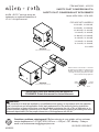 1
1
-
 2
2
-
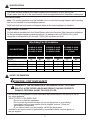 3
3
-
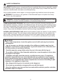 4
4
-
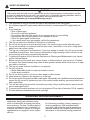 5
5
-
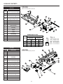 6
6
-
 7
7
-
 8
8
-
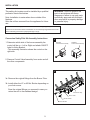 9
9
-
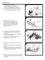 10
10
-
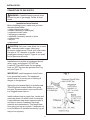 11
11
-
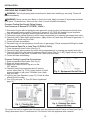 12
12
-
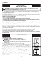 13
13
-
 14
14
-
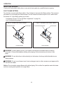 15
15
-
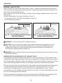 16
16
-
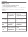 17
17
-
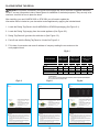 18
18
-
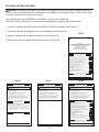 19
19
-
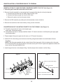 20
20
-
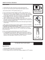 21
21
-
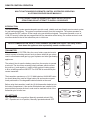 22
22
-
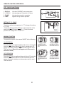 23
23
-
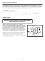 24
24
-
 25
25
-
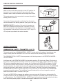 26
26
-
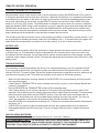 27
27
-
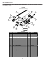 28
28
-
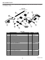 29
29
-
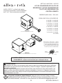 30
30
-
 31
31
-
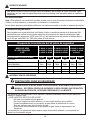 32
32
-
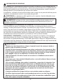 33
33
-
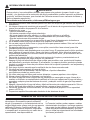 34
34
-
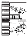 35
35
-
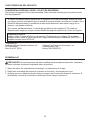 36
36
-
 37
37
-
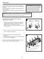 38
38
-
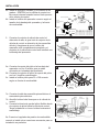 39
39
-
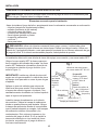 40
40
-
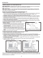 41
41
-
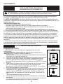 42
42
-
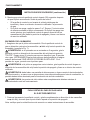 43
43
-
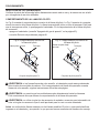 44
44
-
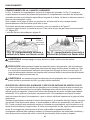 45
45
-
 46
46
-
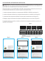 47
47
-
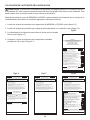 48
48
-
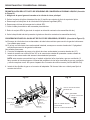 49
49
-
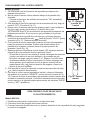 50
50
-
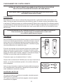 51
51
-
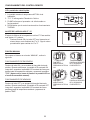 52
52
-
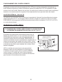 53
53
-
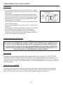 54
54
-
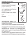 55
55
-
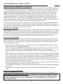 56
56
-
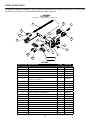 57
57
-
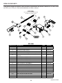 58
58


allen+roth SPK-200L Manual de usuario
- Categoría
- Chimeneas
- Tipo
- Manual de usuario
en otros idiomas
- English: allen+roth SPK-200L User manual
Otros documentos
-
Pleasant Hearth SPK100 Guía de instalación
-
FMI CVDR18 El manual del propietario
-
FMI CPVSA24M El manual del propietario
-
FMI GA9050A-1 El manual del propietario
-
-
-
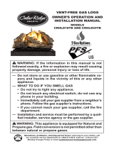 ProCom Heating CRHLD24TB Manual de usuario
-
Remington Hearth Vent-Free Gas Log Heater Manual de usuario
-
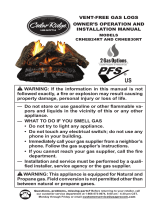 ProCom Heating CRHEB24RTA Manual de usuario

