
DS41035-002 LBT0218
Attuatore per cancelli ad anta AP350
AP350 swing gate operator
Opérateur pour portail battants AP350
Operador para cancelas batientes AP350
Stellantrieb für Flügeltore AP350
41035/001
41035/002
Istruzioni di installazione meccanica, Utilizzo e Manutenzione
Mechanical installation, Use and Maintenance instructions
Notice d’installation mécanique, d’Utilisation et d’Entretien
Instrucciones para la instalacíon mecánica, el Uso y el mantenimiento
Anleitung für die mechanische Installation Gebrauch und Wartung

DS41035-002 2 LBT0218
SCOPO DEL MANUALE
Questo manuale è stato redatto dal costruttore ed è parte integrante del prodotto.
In esso sono contenute tutte le informazioni necessarie per:
• la corretta sensibilizzazione degli installatori alle problematiche della sicurezza;
• la corretta installazione del dispositivo;
• la conoscenza approfondita del suo funzionamento e dei suoi limiti;
• il corretto uso in condizioni di sicurezza;
La costante osservanza delle indicazioni fornite in questo manuale, garantisce la sicurezza dell’uomo, l’economia di esercizio e una più
lunga durata di funzionamento del prodotto. Al fine di evitare manovre errate con il rischio di incidenti, è importante leggere
attentamente questo manuale, rispettando scrupolosamente le informazioni fornite. Tutti i dati sono stati redatti e controllati con la
massima cura, ma non possiamo accettare responsabilità per eventuali errori od omissioni. Ci riserviamo di apportare quelle modifi che
che sono connesse ai progressi tecnologici.
Garanzia
: Le condizioni di garanzia sono da verifi care sul listino vendite in base agli accordi commerciali.
Le istruzioni, i disegni, le fotografi e e la documentazione contenuti nel presente manuale sono di proprietà APRIMATIC S.p.a. e non possono
essere riprodotti in alcun modo, né integralmente, né parzialmente. Il logo “APRIMATIC” è un marchio registrato di APRIMATIC S.p.a.
PURPOSE OF THE MANUAL
This manual was drawn up by the manufacturer and is an integral part of the product.
It contains all the necessary information:
• to draw the attention of the installers to safety related problems
• to install the device properly
• to understand how it works and its limits
• to use the device under safe conditions
Strict observance of the instructions in this manual guarantees safe conditions as well as efficient operation and a long life for the
product. To prevent operations that may result in accidents, read this manual and strictly obey the instructions provided.
All the specifications have been written and verified with our best attention. We do not undertake responsability for possible errors or
omissions. We reserve the right to introduce changes relative to technological progress.
Guarantee
: The guarantee conditions can be checked in the price list on the basis of the commercial agreements.
Instructions, drawings, photos and literature contained herein are the exclusive property of the manufacturer and may not be reproduced
by any means. The “Aprimatic” logo is a trademark registered by Aprimatic S.p.A.
BUT DU MANUEL
Ce manuel a été rédigé par le constructeur et fait partie intégrante du produit.
Il contient toutes les informations nécessaires pour :
• sensibiliser les installateurs aux problèmes liés à la sécurité ;
• installer le dispositif de manière correcte ;
• connaître le fonctionnement et les limites du dispositif ;
• utiliser correctement le dispositif dans des conditions de sécurité optimales ;
Le respect des indications fournies dans ce manuel garantit la sécurité personnelle, une économie de fonctionnement et une longue
durée de vie du produit. Afi n d’éviter des opérations incorrectes et de ne pas risquer des accidents sérieux, lire attentivement ce
manuel et respecter scrupuleusement les informations fournies. Toutes les données ont été rédigées et contrôlées avec le plus grand
soin. Nous n’assumons aucune responsabilité en cas d’erreurs éventuelles ou d’omissions. Nous nous réservons le droit d’apporter des
modifi cations concernant le progrès technologique.
Conditions de garantie
: Vérifiez les conditions de garantie dans le catalogue des ventes sur la base des accords commerciaux.
Les instructions, les dessins, les photos et la documentation contenus dans ce manuel sont la propriété d’APRIMATIC S.p.A. et ne peuvent être
reproduits sous aucune forme, ni intégralement, ni partiellement. Le logo « Aprimatic » est une marque déposée par Aprimatic S.p.A.
ZWECK DES HANDBUCHS
Dieses Handbuch wurde vom Hersteller verfasst und ist ein ergänzender Bestandteil des Produkts.
Es enthält alle nötigen Informationen für:
• die Sensibilisierung der Monteure für Fragen der Sicherheit;
• die vorschriftsmäßige Installation der Vorrichtung;
• die umfassende Kenntnis ihrer Funktionsweise und ihrer Grenzen;
• die vorschriftsmäßige und sichere Benutzung;
Die Beachtung der in diesem Handbuch enthaltenen Anweisungen gewährleistet die Sicherheit der Personen, den wirtschaftlichen Betrieb und
eine lange Lebensdauer des Produkts. Zur Vermeidung von Fehlbedienung und somit Unfallgefahr dieses Handbuch aufmerksam durchlesen
und die Anweisungen genau befolgen. Alle Daten wurden sorgflältigst ausgearbeitet und überprüft. Für eventuelle Fehler oder Auslassungen
übernehmen wir keine Verantwortung. Wir behalten uns vor, solche Änderungen vorzunehmen, welche mit der techologischen Entwicklung im
Zusammenhang stehen.
Garantie
: Die Garantiebedingungen sind der Verkaufspreisliste aufgrund der getroffenen Vereinbarungen zu entnehmen.
Die Anleitungen, Zeichnungen, Fotos und Dokumentationen in diesem Handbuch sind Eigentum von APRIMATIC S.p.A. und dürfen in keiner
Weise ganz oder teilweise reproduziert werden. Das Logo „Aprimatic“ ist ein eingetragenes Warenzeichen der APRIMATIC S.p.a.
OBJETO DEL MANUAL
Este manual ha sido redactado por el constructor y forma parte integrante del producto.
El mismo contiene todas las informaciones necesarias para:
• la correcta sensibilización de los instaladores hacia los problemas de la seguridad
• la correcta instalación del dispositivo
• el conocimiento en profundidad de su funcionamiento y de sus límites
• el correcto uso en condiciones de seguridad
La constante observación de las indicaciones suministradas en este manual, garantiza la seguridad del hombre, la economía del
ejercicio y una mayor duración de funcionamiento del producto. Con el fi n de evitar maniobras equivocadas con riesgo de accidente,
es importante leer atentamente este manual, respetando escrupulosamente las informaciones suministradas. Todos los datos han sido
redactados y comprobados con la máxima atención. No asumimos ninguna responsabilidad en caso de errores posibles u omisiones.
Nos reservamos el derecho de hacer modifi caciones relativas al progreso tecnológico.
Garantía
: Las condiciones de garantía se deben comprobar en la lista de ventas según los acuerdos comerciales estipulados.
Las instrucciones, los dibujos, las fotografías y la documentación que contiene este manual son propiedad de APRIMATIC S.p.a. y no pueden
ser reproducidas en ninguna manera, ni integral ni parcialmente. El logo tipo “Aprimatic” es una marca registrada de Aprimatic S. p. A.

DS41035-002 3 LBT0218
ITALIANO
INDICE
1 TERMINOLOGIA E SIMBOLI ADOTTATI NEL MANUALE ..................................................................... 4
2 NORME DI SICUREZZA E OBBLIGHI DELL’INSTALLATORE ............................................................. 5
2.1 INFORMAZIONI........................................................................................................................... 5
2.2 AVVERTENZE PER L’UTILIZZATORE....................................................................................... 5
3 INSTALLAZIONE...................................................................................................................................... 6
3.1 FISSAGGIO ATTUATORE AP350 .............................................................................................. 6
4 SCHEMA IMPIANTO................................................................................................................................ 7
5 DATI TECNICI.......................................................................................................................................... 7
6 MANUTENZIONE..................................................................................................................................... 8
7 COLLEGAMENTO CAVI.......................................................................................................................... 8
7.1 PROCEDURA TABELLA RIFERIMENTO FUNZIONE CAVI...................................................... 8

DS41035-002 4 LBT0218
1 TERMINOLOGIA E SIMBOLI ADOTTATI NEL MANUALE
• ZONA D’INTERVENTO zona che circoscrive l’area in cui si esegue l’installazione e dove la presenza di una
persona esposta costituisce un rischio per la sicurezza e la salute della persona stessa (Allegato I, 1.1.1 Direttiva
98/37/CEE);
• PERSONA ESPOSTA qualsiasi persona che si trovi interamente o in parte in una zona pericolosa (Allegato I, 1.1.1
- Direttiva 98/37/CEE);
• INSTALLATORE persona incaricata di installare, far funzionare, regolare, eseguire la manutenzione, pulire, riparare
e trasportare il dispositivo (Allegato I, 1.1.1 - Direttiva 98/37/CEE);
• PERICOLO RESIDUO pericolo che non è stato possibile eliminare o sufficientemente ridurre attraverso la
progettazione.
Le indicazioni precedute da questo simbolo contengono informazioni, prescrizioni o
procedure che se non eseguite correttamente possono causare lesioni, morte o rischi a lungo termine per la salute delle
persone e per l’ambiente.
Le indicazioni precedute da questo simbolo contengono procedure o pratiche che, se non
eseguite correttamente, possono causare gravi danni alla macchina o al prodotto.
Le indicazioni precedute da questo simbolo contengono informazioni su qualsiasi soggetto di
particolare importanza: il loro mancato rispetto può comportare la perdita della garanzia contrattuale.
DICHIARAZIONE CE DI CONFORMITA’
(Direttiva Macchine 98/37/CE, Allegato II,parte B)
Si dichiara che il prodotto:
AP350
É conforme ai requisiti della Direttiva 89/392/CEE (macchine) e succ. modifiche.
É conforme ai requisiti delle seguenti altre Direttive CE.
89/336/CEE (compatibilità elettromagnetica) e succ. modifiche
73/23/CEE (bassa tensione) e succ. modifiche
Si dichiara inoltre che sono state applicate le seguenti norme armonizzate:
EN 292 1/2 - Sicurezza del macchinario – principi generali di progettazione
EN 60335-1 - Sicurezza degli apparecchi elettrici d’uso domestico – norme generali
EN55014-1 - Emissioni condotte – potenza irradiata

DS41035-002 5 LBT0218
2 NORME DI SICUREZZA E OBBLIGHI DELL’INSTALLATORE
2.1 INFORMAZIONI
Per lavorare nel pieno rispetto delle norme di sicurezza occorre:
• indossare indumenti di protezione a norma di legge (scarpe antinfortunistiche, occhiali di protezione, guanti ed
elmetto);
• non indossare articoli di abbigliamento che possano impigliarsi (cravatte, bracciali, collane, ecc.).
Un cancello motorizzato costituisce una macchina e deve essere installato secondo quanto previsto dalle leggi,
le norme e i regolamenti in vigore.
Prima dell’installazione deve essere effettuata l’analisi dei rischi sul sito da parte di persone professionalmente
qualifi cate secondo le leggi in vigore per le chiusure motorizzate. Per ottenere un livello di sicurezza adeguato,
l’installazione deve essere eseguita secondo quanto previsto dalle Norme EN 12453 e EN 12445. Nei Paesi extra
CEE, oltre alle Norme citate, fare riferimento a leggi e normative nazionali.
• L’installazione deve essere eseguita da persone professionalmente qualificate.
• L’installazione, i collegamenti elettrici e le regolazioni necessarie devono essere effettuate secondo le leggi e le
norme in vigore.
• Leggere attentamente le istruzioni prima di procedere all’installazione.
• Una non corretta installazione può essere fonte di pericoli.
• Gli imballi non devono essere abbandonati nell’ambiente ma devono essere smaltiti secondo le leggi ed i
regolamenti in vigore.
• Prima di iniziare l’installazione verificare che il prodotto e l’imballo non siano danneggiati.
• Non installare il prodotto in aree dove vi sia il rischio di esplosione: la presenza di gas, polveri o fumi infiammabili
rappresenta una seria minaccia per la sicurezza.
• Verificare che vi siano tutti i franchi di sicurezza e che tutte le zone in cui vi sono rischi di schiacciamento,
cesoiamento od intrappolamento o comunque pericolose siano salvaguardate o protette secondo le norme in vigore
per i cancelli motorizzati.
• Obbligo di delimitare opportunamente la zona di intervento per evitare l’accesso di persone estranee.
• I dispositivi di protezione devono essere installati in seguito ad una analisi dei rischi sul luogo, verificando che siano
marchiati e funzionino secondo le norme in vigore.
• Su ogni installazione devono essere riportati in modo visibile i dati richiesti dalle norme applicabili.
• Prima di collegarsi alla linea di alimentazione verifi care che la potenza disponibile sia coerente con i dati di targa.
Verificare che a monte dell’installazione sia presente un interruttore magnetotermico differenziale adeguato.
• Il produttore della motorizzazione declina ogni responsabilità qualora vengano utilizzati componenti non compatibili
con un corretto e sicuro utilizzo.
• L’installatore deve fornire all’utilizzatore tutte le necessarie informazioni sull’utilizzo dell’automazione, con particolare
riguardo alle procedure per la manovra manuale di emergenza e agli eventuali rischi residui.
2.2 AVVERTENZE PER L’UTILIZZATORE
• Le indicazioni e avvertenze che seguono sono parte integrale ed essenziale del prodotto. Esse devono essere
consegnate all’utilizzatore e devono essere lette attentamente poiché contengono importanti avvertimenti per l’uso e
la manutenzione. Queste istruzioni devono essere conservate e consegnate a tutti i futuri possibili utilizzatori.
• Questa automazione deve essere utilizzata esclusivamente per l’uso cui è destinata. Ogni altro utilizzo è improprio e
quindi pericoloso.
• Evitare di sostare nei pressi delle parti meccaniche in movimento. Non entrare nel raggio d’azione dell’automazione
in movimento. Non tentare di ostacolare od ostruire il movimento dell’automazione perché può essere fonte di
pericolo.
• Non permettere ai bambini di giocare o sostare nel raggio d’azione dell’automazione.
• Tenere sotto controllo i radiocomandi o altri dispositivi di attivazione del movimento in modo da evitare azionamenti
involontari da parte di bambini o estranei.
• In caso di guasto o funzionamento non regolare, togliere alimentazione all’automazione azionando l’interruttore
principale. Non tentare di intervenire o di riparare l’unità principale e contattare chi ha installato l’automazione o un
altro installatore specializzato. Non rispettare questo avvertimento può portare a situazioni di pericolo.
• Tutte le operazioni di riparazione e di manutenzione, incluse quelle di pulizia dell’azionamento, devono essere
effettuate solamente da persone qualificate.
• Per garantire un corretto ed efficiente funzionamento è necessario seguire le istruzioni del produttore e in particolare
fare effettuare una manutenzione periodica da personale specializzato che verifichi soprattutto il regolare
funzionamento dei dispositivi di protezione.
• Tutte le riparazioni e le manutenzioni eseguite devono essere registrate sul registro di manutenzione e rese
disponibili per l’utilizzatore.

DS41035-002 6 LBT0218
3 INSTALLAZIONE
3.1 FISSAGGIO ATTUATORE AP350
L’attuatore AP350 è costruito nelle versioni DESTRO e/o SINISTRO a seconda dell'anta a cui deve essere applicato, le
ante devono essere guardate dall'interno.
L’attuatore AP350 è facilmente installabile su ogni tipo di cancello purché ben bilanciato ed è costruito per ante che non
superino i 300kg di peso ed i 3,5 metri di lunghezza.
Fissare la piastra grande alla colonna rispettando le quote riportate nella tabella e posizionare l’attuatore perfettamente
orizzontale (in bolla) rispetto al proprio asse (Fig. A).
Fissare il motoriduttore alla piastra grande "1" con Il perno e grano in dotazione.
Estendere completamente il tubo inox "3" fino alla fine della corsa, dopo di che riavvitarlo di un giro onde evitare che la
chiocciola interna vada a forzare sull'estremità del tubo.
Fissare la piastra piccola "4" all'estremità dell’attuatore utilizzando grano e perno in dotazione. Fissare la piastra piccola
all'anta mantenendo orizzontale l’attuatore (in bolla).
Posizionare i fermi meccanici sia in apertura che in chiusura (Fig. B).
Per effettuare una MANOVRA MANUALE O DI EMERGENZA, agire sullo sblocco "2" con la chiave in dotazione.
TIPO ROTAZIONE A 95° ROTAZIONE A 110°
W X Y W X Y
400 1130 160 210 1130 170 160

DS41035-002 7 LBT0218
4 SCHEMA IMPIANTO
5 DATI TECNICI
Alimentazione ..........................................................................................................................................................230 Vac
Potenza ......................................................................................................................................................................350 W
Corrente assorbita .........................................................................................................................................................1,8A
Velocità lineare dello stelo........................................................................................................................................1,8 cm/s
Corsa dello stelo ..................................................................................................................................................... 400 mm
Lunghezza max anta ..............................................................................................................................................2 -3- 4 m
Peso max anta ..........................................................................................................................................................350 Kg
Grado di protezione ......................................................................................................................................................IP 44
Protezione termica ........................................................................................................................................................150°
Cicli/ora ............................................................................................................................................................................ 18
Temperatura di funzionamento .....................................................................................................................-20°C ÷ +70°C
Tipo lubrificante .................................................................................................................................................permanente
Condensatore .................................................................................................................................................................8µF
Peso motore ..................................................................................................................................................................6 Kg
N° DESCRIZIONE
1
Attuatore
2
Fotocellula
3
Colonna fotocellula
4
Selettore chiave
5
Centralina elettronica
6
Antenna
7
Lampeggiante

DS41035-002 8 LBT0218
6 MANUTENZIONE
La manutenzione dell'apparecchiatura deve essere effettuata solo ed esclusivamente da un
tecnico specializzato ed autorizzato dalla casa costruttrice. Qualsiasi operazione di mantenimento o controllo
dell'apparecchiatura deve esser effettuata in assenza dei tensione di alimentazione.
• Manutenzione ordinaria: ogni volta che si avverte la necessità, e comunque ogni 6 mesi, si raccomanda di
verificare lo stato di funzionamento dell'apparecchiatura.
• Manutenzione straordinaria: se dovessero rendersi necessari interventi importanti sull'apparecchiatura, si
raccomanda le rimozione della stessa, per consentire la riparazione in laboratorio ad opera di tecnici della casa
costruttrice o da essa autorizzati.
La casa costruttrice si solleva da qualsiasi responsabilità per la mancata osservanza delle norme sopra
descritte.
7 COLLEGAMENTO CAVI
7.1 PROCEDURA TABELLA RIFERIMENTO FUNZIONE CAVI
Colore cavo Attuatore destro “D” Attuatore sinistro “S”
Grigio Comune Comune
Nero Estrae Stelo (Apertura) Ritrae Stelo (Chiusura)
Marrone Ritrae Stelo (Chiusura) Estrae Stelo (Apertura)
Giallo-Verde Terra Terra

DS41035-002 9 LBT0218
ENGLISH
TABLE OF CONTENTS
1 TERMINOLOGY AND SYMBOLS USED IN THIS MANUAL................................................................. 10
2 SAFETY STANDARDS AND INSTALLER OBLIGATIONS ................................................................... 11
2.1 INFORMAtION........................................................................................................................... 11
2.2 WARNINGS FOR THE USER ................................................................................................... 11
3 INSTALLATION...................................................................................................................................... 12
3.1 AP350 OPERATOR MOUNTING .............................................................................................. 12
4 SYSTEM DIAGRAM............................................................................................................................... 13
5 TECHNICAL DATA................................................................................................................................. 13
6 MAINTENANCE ..................................................................................................................................... 14
7 CABLES CONNECTION........................................................................................................................ 14
7.1 CABLES FUNCTION REFERENCE TABLE ............................................................................. 14

DS41035-002 10 LBT0218
1 TERMINOLOGY AND SYMBOLS USED IN THIS MANUAL
• INSTALLATION AREA: the area required to perform installation in which the presence of persons is hazardous for
the persons themselves (Appendix I, 1.1.1 Directive 98/37/EEC);
• EXPOSED PERSON any person located in full or in part in a hazardous area (Appendix I, 1.1.1 - Directive
98/37/EEC);
• INSTALLER person responsible for installation, operation, adjustment, maintenance, cleaning, repair and
transporting of the device (Appendix I, 1.1.1 - Directive 98/37/EEC);
• RESIDUAL HAZARD risks which cannot be eliminated or suffi ciently reduced as part of the design process
This symbol is used to mark information, instructions and procedures which if ignored could
lead to death and serious injury and which could create a long-term health and environmental hazard.
This symbol is used to mark information, instructions and procedures which if ignored can
cause serious damage to the machine or to the product.
The symbol is used to mark important information which if ignored could void your warranty.
CE CONFORMITY DECLARATION
(machinery Directive 98/37/CE, Attached II, part B)
declares that the product:
AP350
Is suitable with requirement of the Directive 89/392/CEE and next modifications
Is suitable with following requirement of other Directives CE
89/336/CEE (electromagnetic compatibility) and next modifications
73/23/CEE (low tension) and next modifications
declare moreover that they have been applied the following harmonized norms:
EN 292 1/2 - Emergency of the machinery -general principles of planning
EN 60335-1 - Emergency of the apparatuses electrical workers of domestic use – general norms
EN55014-1 - Conduct Emissions - irradiated power

DS41035-002 11 LBT0218
2 SAFETY STANDARDS AND INSTALLER OBLIGATIONS
2.1 INFORMATION
Installers must proceed as follows to conform with safety standards:
• wear protective clothing (accident-prevention footwear, goggles, gloves and helmet);
• do NOT wear clothing or jewellery that may become trapped (ties, bracelets, necklaces, etc).
A motorised gate is a machine and as such must be installed in accordance with health and safety standards
and legislation. Before installation a risk analysis for the installation site must be performed by professionally
qualified personnel in accordance with current legislation for motorised gates (refer to EN 12453 and EN 12445).
In countries outside the EU refer to national regulations and legislation as well as the standards specified.
• Only professionally qualifi ed personnel should install the product.
• Installation, electrical connections and settings must conform with current legislation.
• Carefully read the instruction manual before installation
• Incorrect installation may be a source of hazards
• Packaging must be disposed of in accordance with current legislation. Do NOT litter the environment
• Check that the product and packaging are undamaged before starting installation
• Do NOT install the product in areas where there is a risk of explosion. Gas, powders and fl ammable fumes
represent a health hazard
• Check that all safety measures are taken and that people are protected from areas posing a risk of crushing, cutting,
trapping and any other hazard, in accordance with current legislation for motorised gates
• The installation area must be cordoned off to prevent access by unauthorised personnel
• Protection devices must be installed following risk analysis of the site. Check that the protection devices are marked
and that they function in accordance with current legislation
• The data required by applicable legislation must be clearly visible on the installation
• Check that the mains power available is compatible with the data on the identifi cation plate before connecting the
operator to the mains power supply. A suitable differential overload switch must be installed upstream of the
operator
• The manufacturer of the operator declines all responsibility if components are used which are incompatible with
correct and safe use.
• The installer must provide the user with all the information need to operate the device with particular attention given
to manual operation in the event of an emergency and any residual risks.
2.2 WARNINGS FOR THE USER
• The instructions and warnings given below are a vital and integral part of the product. The instructions and warnings
must be given to the user and then read carefully because they include important warnings for use and
maintenance. The instructions must be kept and given to all future users.
• The operator must be used exclusively for the purpose for which it is designed. All improper use is forbidden and
hazardous.
• Keep away from moving mechanical parts. Keep away from the operating range of the device during operation. Do
not try to obstruct the movement of the device as such action may be hazardous.
• Keep children away from the operating range of the device at all times.
• Keep remote control and other control units in a safe place to prevent use by children or unauthorised people.
• In the event of any faults disconnect the operator from the mains power supply using the main switch. Do not try to
repair the main unit. Contact the installer or other specialist assistance centre. Failure to follow these instructions
may result in hazardous situations.
• All maintenance, including cleaning, must be performed by qualifi ed personnel.
• Follow the manufacturer’s instructions and refer to specialist personnel to perform routine maintenance, particularly
verification of correct functioning of protection devices, to ensure correct and efficient functioning of the operator.
• All repairs and maintenance must be recorded on the maintenance record and then made available to the user.

DS41035-002 12 LBT0218
3 INSTALLATION
3.1 AP350 OPERATOR MOUNTING
The AP350 operator has been made in RIGHT and/or LEFT version depending on the leaf on which it will be installed.
The leaves must be considered from the internal side (garden).
The AP350 operator is easily installed on any type of gate, as long as the gate is well balanced.
The AP350 operator has been constructed for gate wings that do not exceed 300 kg in weight and 3,5 meters in length.
Fix the large plate to the column respecting the measurements shown in the table and position the cylinder perfectly
horizontal (check with a sprit-level) and with respect to Its axis (Fig. A).
Fix the gear-motor to the large plate "1" using the pin and grub-screw supplied.
AP350 OPERATOR MOUNTING Completely extend the stainless steel tube "3" up to the end of its stroke, then screw it
back for one turn (at least 1 cm) to make the gate wing close perfectly.
Fix the small plate "4" to the end of the operator using the pin and grub-screw supplied. Fix the small plate to the gate
wing, keeping the operator horizontal (check with a sprit-level).
Position the mechanical doorstops in both the open and closed positions (Fig. B).
MANUAL OR EMERGENCY MANOEUVRE: Operate unlocking device "2" using the key supplied.
TYPE ROTATION 95° ROTATION 110°
W X Y W X Y
400 1130 160 210 1130 170 160

DS41035-002 13 LBT0218
4 SYSTEM DIAGRAM
5 TECHNICAL DATA
Power supply ...........................................................................................................................................................230 Vac
Absorbed power .........................................................................................................................................................350 W
Absorbed current............................................................................................................................................................1,8A
Rod speed................................................................................................................................................................1,8 cm/s
Usable stroke........................................................................................................................................................... 400 mm
Maximum lenght per leaf.........................................................................................................................................2 -3- 4 m
Maximum weight per leaf ...........................................................................................................................................350 Kg
Housing protection........................................................................................................................................................IP 44
Termic Protection...........................................................................................................................................................150°
Cycles/h ............................................................................................................................................................................18
Operating temperature...................................................................................................................................-20°C ÷ +70°C
Lubrification..............................................................................................................................................permanent grease
Capacitor.........................................................................................................................................................................8µF
Motor Weight..................................................................................................................................................................6 Kg
N° DESCRIPTION
1
Swing gate operator
2
Photocell
3
Photocell base
4
Lock
5
Electronic control unit
6
Signal receiver
7
Flashing

DS41035-002 14 LBT0218
6 MAINTENANCE
The maintenance of the equipment shall be carried out only by a specialist technician and
authorized by the manufacturer. Any operation of the maintenance or control of the equipment shall be carried out in the
absence of voltage.
• ordinary maintenance: every time you need for it, and in any event every 6 months, it is recommended to
check the functioning of the equipment.
• extraordinary maintenance: if may be necessary major interventions on the equipment, it is recommended
that the removal of the same, to allow the repair in the laboratory by technicians on the manufacturer or
authorized.
The manufacturer is raised from any liability for the failure to comply with the rules described above.
7 CABLES CONNECTION
7.1 CABLES FUNCTION REFERENCE TABLE
Cable colour “D” right gate operator “S” left gate operator
Gray Common Common
Black Pull Piston rod (Opening) Pull back Piston rod (Closing)
Brown Pull back Piston rod (Closing) Pull Piston rod (Opening)
Yellow-Green Ground Ground

DS41035-002 15 LBT0218
FRANÇAIS
SOMMAIRE
1 TERMINOLOGIE ET SYMBOLES UTILISÉS DANS LE MANUEL........................................................ 16
2 NORMES DE SÉCURITÉ ET OBLIGATIONS DE L’INSTALLATEUR .................................................. 17
2.1 INFORMATIONS ....................................................................................................................... 17
2.2 MISES EN GARDE POUR L’UTILISATEUR............................................................................. 17
3 INSTALLATION...................................................................................................................................... 18
3.1 FIXATION OPÉRATEUR AP350............................................................................................... 18
4 SCHÉMA DU SYSTÈME........................................................................................................................ 19
5 DONNÉES TECHNIQUES..................................................................................................................... 19
6 ENTRETIEN........................................................................................................................................... 20
7 CONNEXIONS DES CÂBLES................................................................................................................ 20
7.1 TABLE DE REFERENCE FONCTION DES CABLES............................................................... 20

DS41035-002 16 LBT0218
1 TERMINOLOGIE ET SYMBOLES UTILISÉS DANS LE MANUEL
• ZONE D’INTERVENTION zone qui circonscrit la zone où l’on effectue l’installation et où la présence d’une personne
exposée représente un risque pour la sécurité et la santé de cette personne (Annexe I, 1.1.1 Directive 98/37/CEE);
• PERSONNE EXPOSEE : toute personne se trouvant entièrement ou partiellement dans une zone dangereuse
(Annexe I, 1.1.1 - Directive 98/37/CEE);
• INSTALLATEUR personne préposée à l’installation, au fonctionnement, au réglage, à l’entretien, au nettoyage et au
transport du dispositif (Annexe I, 1.1.1 Directive 98/37/CEE);
• RISQUE RÉSIDUEL risque qui n’a pas pu être éliminé ou réduit suffi samment pendant la phase de conception.
Les indications précédées de ce symbole mentionnent des informations, des prescriptions
ou des procédures qui, si elles ne sont pas effectuées correctement, peuvent provoquer des lésions graves voire
mortelles ou des risques à long terme pour la santé des personnes et pour l’environnement.
Les indications précédées de ce symbole mentionnent des procédures ou des pratiques qui,
si elles ne sont pas effectuées correctement, peuvent endommager sérieusement la machine ou le produit.
Les indications précédées de ce symbole mentionnent des informations importantes ; le non-
respect de ces indications peut invalider la garantie contractuelle.
DÉCLARATION CE DE CONFORMITÉ
(Directive Machines 98/37/CE, Annexes II, partie B)
On déclare que produit :
AP350
Il est conformément aux qualités de la Directive 89/392/CEE (des machines) et suivant modifications
Il est conformément aux qualités des suivantes autres Directives CE
89/336/CEE (compatibilité électromagnétique) et suivant modifications
73/23/CEE (basse tension) et suivant modifications
On déclare en outre qu'elles ont été appliquées les suivantes règles harmonisées :
EN 292 1/2 - Sûreté de l'outillage - principes généraux de projet
EN 60335-1 - Sûreté des appareils électriques d’emploie domestique – règles générales
EN55014-1 - Émissions conduite - puissance rayonnée

DS41035-002 17 LBT0218
2 NORMES DE SÉCURITÉ ET OBLIGATIONS DE L’INSTALLATEUR
2.1 INFORMATIONS
Pour travailler dans le respect des normes de sécurité, il faut:
• utiliser des vêtements conformes aux dispositions légales (chaussures de sécurité, lunettes de protection, gants et
casque de protection);
• éviter de porter des objets qui peuvent s’accrocher (cravates, bracelets, colliers, etc.).
Un portail motorisé est une machine et doit être installé conformément aux dispositions de lois, aux normes et
aux règlementations en vigueur. Avant d’effectuer l’installation des personnes professionnellement
compétentes doivent procéder à une analyse des risques sur le site de l’installation, conformément aux normes
en vigueur pour les portails motorisés (EN12453 et EN12445). Dans les pays extracommunautaires, se
conformer non seulement aux normes citées mais
également aux lois et aux réglementations nationales.
• L’installation doit être effectuée par des personnes professionnellement compétentes.
• L’installation, les branchements électriques et les réglages nécessaires doivent être effectués selon les lois et les
normes en vigueur.
• Lire attentivement les instructions avant d’installer le produit.
• Une installation incorrecte peut constituer un danger.
• Les emballages ne doivent pas être jetés dans la nature, mais doivent être éliminés en conformité avec les normes
et les règlementations en vigueur.
• Avant de commencer l’installation, vérifi er que le produit et l’emballage ne sont pas endommagés.
• Ne pas installer le produit dans des zones à risque explosion : la présence de gaz, poussières ou fumées infl
ammables représente une sérieuse menace pour la sécurité.
• Vérifi er la présence des dispositifs de sécurité et que toutes les zones présentant des risques d’écrasement,
cisaillement, ou happement ou de toute manière dangereuses sont munies de protections conformément aux
normes en vigueur pour les portails motorisés.
• Obligation de délimiter avec des barrières la zone d’intervention pour interdire l’accès aux personnes non habilitées.
• Les dispositifs de protection doivent être installés après une analyse des risques effectuée sur le site ; vérifi er
également qu’ils sont marqués et qu’ils fonctionnement selon les normes en vigueur.
• Sur chaque installation doivent fi gurer, de façon visible, les données prescrites par les normes applicables.
• Avant d’effectuer le branchement de la ligne d’alimentation, vérifi er que la puissance disponible est conforme aux
donne nominales. Vérifi er la présence d’un disjoncteur magnétothermique différentiel approprié en amont de
l’installation.
• Le fabricant de la motorisation décline toute responsabilité quant à l’utilisation de composants incompatibles avec
une utilisation correcte et en conditions de sécurité.
• L’installateur doit fournir toutes les informations concernant le fonctionnement de l’automatisme, particulièrement au
sujet des procédures de manoeuvre manuelle en cas d’urgence et des risques résiduels éventuels.
2.2 MISES EN GARDE POUR L’UTILISATEUR
• Les indications et les mises en garde fi gurant ci-après font partie intégrante et essentielle du produit. Elles doivent
être remises à l’utilisateur et doivent être lues attentivement parce qu’elles contiennent des informations importantes
pour l’utilisation et l’entretien. Ces instructions doivent être conservées et remises à tous les utilisateurs futurs
éventuels.
• Cet automatisme doit être utilisé exclusivement pour l’usage pour lequel il est prévu. Toute autre utilisation est
impropre et donc dangereuse.
• Eviter de stationner près des pièces mécaniques en mouvement. Ne pas entrer dans le rayon d’action de
l’automatisme en mouvement. Toute tentative d’empêchement ou de blocage du mouvement de l’automatisme peut
constituer un danger.
• Empêcher les enfants de jouer ou de stationner dans le rayon d’action de l’automatisme.
• Surveiller les radiocommandes et tout autre dispositif d’activation du mouvement pour éviter tout actionnement
involontarie par les enfants ou les personnes non habilitées.
• En cas de panne ou de fonctionnement irrégulier, couper l’alimentation à l’automatisme en utilisant l’interrupteur
principal. Ne pas tenter d’intervenir ou de réparer l’unité principale et s’adresser à l’installateur de l’automatisme ou
à un autre installateur spécialisé. Le non-respect de cette mise en garde peut engendrer des situations
dangereuses.
• Toutes les interventions de réparation et d’entretien, y compris celles de nettoyage de l’actionnement ne doivent ê
effectuées que par des personnes qualifiées.
• Pour garantir un fonctionnement correct et effi cace il faut suivre les instructions du fabricant et faire effectuer
l’entretien périodique par du personnel spécialisé qui vérifi e notamment le bon fonctionnement des dispositifs de
protection.
• Toutes les interventions de réparation et d’entretien effectuées doivent être notées sur le registre d’entretien et
mises à dispositions de l’utilisateur.

DS41035-002 18 LBT0218
3 INSTALLATION
3.1 FIXATION OPÉRATEUR AP350
L’opérateur AP350 a été conçu dans la version DROITE et/ou GAUCHE selon le vantail sur le quel doit etre instailé, les
vantaux doivent etre considerés par l'interieur (jardin).
L’opérateur AP350 est facile à installer sur tout type de portail
à
condition qu'il soit bien équilibré.
L’opérateur AP350 est construit pour des battants qui ne dépassent pas 300 kg de poids et 3,5 mètres de longueur.
Fixer la grande plaque
à
la colonne en respectant les cotes reportées dans le tableau et positionner le piston
parfaitement
à
l'horizontal (de niveau) par rapport
à
son propre axe (Fig. A).
Fixer le motoréducteur à la grande plaque "1" avec le pivot et le grain fournis.
Tirer complètement le tuyau inox "3" jusqu'à la fin de la course, après quoi le revisser d'un tour (au moins 1 cm) pour
avoir une fermeture parfaite du battant.
Fixer la petite plaque "4" à l'extrémité du piston en utilisant grain et pivot fournis. Fixer la petite plaque au battant en
maintenant le piston à l'horizontal (de niveau).
Positionner les cales mécaniques des portes aussi bien en ouverture qu'en fermeture (Fig. B).
MANŒUVRE MANUELLE OU D'URGENCE : Agir sur le bloc "2" avec la clé fournie.
TYPE ROTATION 95° ROTATION 110°
W X Y W X Y
400 1130 160 210 1130 170 160

DS41035-002 19 LBT0218
4 SCHÉMA DU SYSTÈME
5 DONNÉES TECHNIQUES
Alimentation .............................................................................................................................................................230 Vac
Puissance absorbée....................................................................................................................................................350 W
Courant absorbée ..........................................................................................................................................................1,8A
Vitesse linéaire.........................................................................................................................................................1,8 cm/s
Course utile.............................................................................................................................................................. 400 mm
Longueur max vantail..............................................................................................................................................2 -3- 4 m
Poids max vantail.......................................................................................................................................................350 Kg
Degré de protection ......................................................................................................................................................IP 44
Protection termique........................................................................................................................................................150°
Cylces/h ............................................................................................................................................................................ 18
Témperature d'emploi ....................................................................................................................................-20°C ÷ +70°C
Lubrification.....................................................................................................................................................fat permanent
Condensateur..................................................................................................................................................................8µF
Poids moteur..................................................................................................................................................................6 Kg
N° DESCRIPTION
1
Opérateur pour portail battans
2
Cellule photo-électrique
3
Colonne Cellule photo-électrique
4
Serrure
5
Programmateur électronique
6
Antenne
7
Lumière clignote

DS41035-002 20 LBT0218
6 ENTRETIEN
: L'entretien du matériel doit être effectué que par un spécialiste technicien et autorisé par le
fabricant. Toute opération de l'entretien ou de contrôle de l'équipement sera effectuée en l'absence de tension.
• entretien ordinaire : chaque fois que vous avez besoin pour cela, et en tout cas tous les 6 mois, il est
recommandé de vérifier le fonctionnement de l'équipement.
• extraordinaire entretien : il peut être nécessaire interventions majeures sur le matériel, il est recommandé que
la suppression de la même, pour permettre la réparation dans le laboratoire par des techniciens sur le fabricant
ou autorisé.
Le fabricant est soulevé de toute responsabilité de l'échec de se conformer aux règles décrites plus haut.
7 CONNEXIONS DES CÂBLES
7.1 TABLE DE REFERENCE FONCTION DES CABLES
Couleur du câble Opérateur droite “D” Opérateur gauche “S”
Gris Commun Commun
Noir Extraits la tige de piston (Ouverture) Rétracte la tige de piston (Fermeture)
Brun Rétracte la tige de piston (Fermeture) Extraits la tige de piston (Ouverture)
Jaune-Vert Terre Terre

DS41035-002 21 LBT0218
ESPAÑOL
SUMARIO
1 TÉRMINOS Y SÍMBOLOS UTILIZADOS EN EL MANUAL ................................................................... 22
2 NORMAS DE SEGURIDAD Y OBLIGACIONES DEL INSTALADOR................................................... 23
2.1 INFORMACIÓN ......................................................................................................................... 23
2.2 ADVERTENCIA PARA EL USUARIO........................................................................................ 23
3 INSTALACIÓN........................................................................................................................................ 24
3.1 ACTUADOR MONTAJE AP350................................................................................................. 24
4 ESQUEMA DEL SISTEMA..................................................................................................................... 25
5 DATOS TÉCNICOS................................................................................................................................ 25
6 MANTENIMENTO .................................................................................................................................. 26
7 CONEXIÓN DE CABLES....................................................................................................................... 26
7.1 TABLA DE REFERENCIA FUNCIONES DE CABLES.............................................................. 26

DS41035-002 22 LBT0218
1 TÉRMINOS Y SÍMBOLOS UTILIZADOS EN EL MANUAL
• ZONA DE INTERVENCIÓN zona che circunscribe la zona en la cual se realiza la instalación y donde la presencia
de una persona expuesta constituye un riesgo para la seguridad y la salud de la persona misma (Anexo I, 1.1.1
Directiva 98/37/CEE);
• PERSONA EXPUESTA cualquier persona que se encuentre total o parcialmente dentro de una zona peligrosa
(Anexo I, 1.1.1 Directiva 98/37/CEE);
• INSTALADOR persona encargada de instalar, hacer funcionar, regular, efectuar el mantenimiento, limpiar, reparar
y transportar el dispositivo (Anexo I, 1.1.1 Directiva 98/37/CEE);
• PELIGRO RESIDUAL peligro que no ha sido posible eliminar o por lo menos reducir durante el proyecto.
Las indicaciones que están precedidas por este símbolo contienen información,
prescripciones o procedimientos que, si no se ejecutan correctamente, pueden causar lesiones, la muerte o riesgos a
largo plazo para la salud de las personas y para el ambiente.
Las indicaciones que están precedidas por este símbolo contienen procedimientos o
prácticas que, si no se ejecutan correctamente, pueden causar daños graves a la máquina o al producto.
Las indicaciones que están precedidas por este símbolo contienen información sobre
cualquier asunto de especial importancia: el incumplimiento de las mismas puede implicar la pérdida de la garantía
contractual.
DECLARACIÓN CE DE CONFORMIDAD
directivas de CONFORMIDAD 98/37/CE, unidas II, parte B)
declara que el producto:
AP350
se ajusta con el requisito del 89/392/CEE directivo y siguente modificaciones
se ajusta con los requisitos de esas otras directivas CE:
89/336/CEE (compatibilidad electromágnetica) y siguente Modificaciones;
73/23/CEE (tensión baja) y siguente modificaciones.
declaran por otra parte que se han aplicado las normas armonizadas siguientes:
EN 292 el 1/2 - seguridad de la maquinaria - principios generales del planeamiento
EN 60335-1 - Seguridad de aparatos eletricos de uso domesitco
EN55014-1 - Emisiones de la conducta - energía irradiada

DS41035-002 23 LBT0218
2 NORMAS DE SEGURIDAD Y OBLIGACIONES DEL INSTALADOR
2.1 INFORMACIÓN
Para trabajar respetando las normas de seguridad es necesario:
• ponerse las prendas de protección según las normas de ley (calzado de seguridad, gafas de protección, guantes y
casco);
• no usar prendas de vestir que puedan engancharse (corbatas, brazaletes, collares, etc..).
La cancela motorizada es una máquina y debe instalarse según lo previsto por la ley, las normativas y los
reglamentos en vigor.
Antes de la instalación personas profesionalmente competentes deben realizar un análisis de los riesgos en el
lugar de la instalación, según las normas en vigor para las cancelas motorizadas (consultar EN 12453 y
EN12445). En los países no pertenecientes a la CEE, además de las normas citadas debe hacerse referencia a
las leyes y normativas nacionales.
• La instalación debe ser efectuada por personal profesionalmente cualifi cado.
• La instalación, las conexiones eléctricas y los ajustes necesarios deben ser realizados según las leyes y las normas
en vigor.
• Leer atentamente las instrucciones antes de realizar la instalación.
• Una instalación incorrecta puede ser fuente de peligros.
• No abandonar los embalajes en el ambiente, eliminarlos según las leyes y los reglamentos en vigor.
• Antes de iniciar la instalación comprobar que el producto y el embalaje no están dañados.
• No instalar el producto en zonas con riesgo de explosión: la presencia de gas, polvo o humos infl amables
representa una grave amenaza para la seguridad.
• Verificar que existen dispositivos de seguridad y que todas las zonas en las cuales existen riesgos de
aplastamiento, corte o atrapamiento o, en todo caso, sean peligrosas, estén protegidas según las normas en vigor
para las cancelas motorizadas.
• Es obligatorio delimitar de manera apropiada la zona de intervención para evitar el acceso a personas extrañas.
• Los dispositivos de protección deben instalarse después de haber realizado un análisis de los riesgos en el lugar,
verificando que los mismos están dotados del marcado correspondiente y que funcionan según las normas
vigentes.
• En cada instalación deben indicarse de manera visible los datos requeridos por las normas aplicables.
• Antes de conectarse a la línea de alimentación, verifi car que la potencia disponible es conforme con los datos de la
placa. Verificar que línea arriba de la instalación exista un interruptor magnetotérmico diferencial adecuado.
• El fabricante de la motorización declina toda responsabilidad si se utilizan componentes que no son compatibles
con un uso correcto y seguro.
• El instalador debe suministrar al usuario toda la información necesaria sobre la utilización de la automatización,
especialmente en lo que se refiere a los procedimientos para la maniobra manual de emergencia y sobre los
posibles riesgos residuales.
2.2 ADVERTENCIA PARA EL USUARIO
• Las indicaciones y advertencias que se proporcionan a continuación son parte integral y esencial del producto. Las
mismas deben entregarse al usuario y deben leerse atentamente porque contienen advertencias importantes para
el uso y el mantenimiento. Estas instrucciones deben conservarse y entregarse a todos los posibles usuarios
futuros.
• Esta automatización debe utilizarse exclusivamente para el uso al cual ha sido destinada. Todo uso que no sea el
indicado es impropio y por tanto peligroso.
• Evitar permanecer cerca de piezas mecánicas que se mueven. No entrar en el radio de acción de la automatización
mientras se está moviendo. No tratar de obstaculizar u obstruir el desplazamiento de la automatización porque
puede ser fuente de peligros.
• No permitir a los niños jugar o permanecer dentro del radio de acción de la automatización.
• Tener bajo control los telemandos u otros dispositivos de activación del movimiento para evitar que niños o
personas extrañas los accionen involuntariamente.
• En caso de averías o funcionamiento irregular, cortar la alimentación a la automatización accionando el interruptor
principal. No tratar de intervenir o reparar la unidad principal y contactar con el instalador de la automatización u
otro instalador especializado. El incumplimiento de esta advertencia puede conducir a situaciones peligrosas.
• Todas las operaciones de reparación y de mantenimiento, incluso las de limpieza del accionamiento, deben ser
realizadas únicamente por personas cualifi cadas.
• Para garantizar un funcionamiento correcto y eficiente es imprescindible seguir las instrucciones del fabricante.
Especialmente hacer que personal especializado realice el mantenimiento periódico para verificar que los
dispositivos de protección funcionan correctamente.
• Todas las reparaciones y las operaciones de mantenimiento realizadas deben ser registradas en el registro de
mantenimiento y estar disponibles para el usuario.

DS41035-002 24 LBT0218
3 INSTALACIÓN
3.1 ACTUADOR MONTAJE AP350
El actuator AP350 ha sido construido en las versiones derecha e izquirda, segun la hoja en la cual se debe instalar. Las
hojas se tienen que ver desde el interno (jardin).
El actuator AP350 se puede instalar facilmente en cada tipo de reja, siempre que sea bien equilibrado.
El actuator AP350 se ha construido para puertas que no superen los 300 kg de peso y los 3,5 metros de longitud.
Fijar la placa grande en la columna respetando las cotas indicadas en la tabla y posicionar el pistón de forma
perfectamente horizontal (nivelado) con respecto a su eje (Fig. A).
Fijar el motoreductor a la placa grande "1" con el perno
y
el tornillo prisionero entregado.
Extender completamente el tubo inoxidable "3" hasta el final de la carrera; después de eso volver a atornillarlo de una
vuelta (por lo menos 1 cm), para conseguir un perfecto cierre de la puerta.
Fijar la placa pequeña "4" en la extremidad del piston utilizando un tornillo prisionero y el perno entregado. Fijar la placa
pequeña en la puerta mantenìendo el pistón horizontal (nivelado).
Posicionar los topes mecánicos de las puertas tanto en apertura como en cierre (Fig. B).
MANIOBRA MANUAL O DE EMERGENCIA: Intervenir en el desbloqueo "2" con la liave entregada.
TIPO ROTACIÓN 95° ROTACIÓN 110°
W X Y W X Y
400 1130 160 210 1130 170 160

DS41035-002 25 LBT0218
4 ESQUEMA DEL SISTEMA
5 DATOS TÉCNICOS
Alimentacion.............................................................................................................................................................230 Vac
Poder ..........................................................................................................................................................................350 W
Consumo de corriente....................................................................................................................................................1,8A
Velocidad lineal........................................................................................................................................................1,8 cm/s
Corsa util.................................................................................................................................................................. 400 mm
Largura max de la hoia ...........................................................................................................................................2 -3- 4 m
Peso max de la hoja...................................................................................................................................................350 Kg
Grado de proteccion......................................................................................................................................................IP 44
Proteccion termica .........................................................................................................................................................150°
Ciclos/h ............................................................................................................................................................................. 18
Temperatura de trabajo..................................................................................................................................-20°C ÷ +70°C
Tipo de lubricante.....................................................................................................................................grasa permanente
Condensador...................................................................................................................................................................8µF
Peso motor.....................................................................................................................................................................6 Kg
N° DESCRIPCIÓN
1
Motorreductor para puertas de hojas
2
Fotocelda
3
Columna Fotocelda
4
Cerradura
5
Programador eletronico
6
Antena
7
Luz intermitente

DS41035-002 26 LBT0218
6 MANTENIMENTO
El mantenimiento de los equipos serán llevadas a cabo sólo por un especialista técnico y
autorizada por el fabricante. Cualquier operación de mantenimiento o el control del equipo será llevado a cabo en la
ausencia de tensión.
• mantenimiento ordinario: cada vez que necesita para ella, y en cualquier caso cada 6 meses, se recomienda
para comprobar el funcionamiento del equipo.
• extraordinario mantenimiento: si puede ser necesario intervenciones importantes sobre el equipo, se
recomienda que la supresión de la misma, para permitir la reparación en el laboratorio por técnicos en el
fabricante o autorizados.
El fabricante está planteado desde cualquier responsabilidad por el incumplimiento de las reglas descritas
anteriormente.
7 CONEXIÓN DE CABLES
7.1 TABLA DE REFERENCIA FUNCIONES DE CABLES
Color del cable Actuador derecho “D” Actuador izquierdo “S”
Gris Común Común
Negro Tire de la varilla del vástago (Apertura) Tire hacia atrás del vástago (Cierre)
Marrón Tire hacia atrás del vástago (Cierre) Tire de la varilla del vástago (Apertura)
Amarillo-Verdoso Tierra Tierra

DS41035-002 27 LBT0218
DEUTSCH
INHALTSVERZEICHNIS
1 IM HANDBUCH VERWENDETE TERMINOLOGIE UND SYMBOLE ................................................... 28
2 SICHERHEITSNORMEN UND PFLICHTEN DES INSTALLATEURS .................................................. 29
2.1 INFORMATIONEN..................................................................................................................... 29
2.2 WARNHINWEISE FÜR DEN ANWENDER............................................................................... 29
3 INSTALLATION...................................................................................................................................... 30
3.1 BEFESTIGUNG DES STELLANTRIEBS AP350....................................................................... 30
4 ANLAGENPLAN..................................................................................................................................... 31
5 TECHNISCHE DATEN........................................................................................................................... 31
6 INSTANDHALTUNG............................................................................................................................... 32
7 KABELANSCHLÜSSE ........................................................................................................................... 32
7.1 VERFAHREN BEZUGSTABELLE DER KABELFUNKTION..................................................... 32

DS41035-002 28 LBT0218
1 IM HANDBUCH VERWENDETE TERMINOLOGIE UND SYMBOLE
• EINGRIFFSBEREICH - der Bereich, in dem die Installation erfolgt und wo die Sicherheit oder die Gesundheit einer
Person durch den Aufenthalt in diesem Bereich gefährdet wird (Anhang I, 1.1.1 Richtlinie 98/37/EWG);
• GEFÄHRDETE PERSON - eine Person, die sich ganz oder teilweise in einem Gefahrenbereich befindet; (Anhang I,
1.1.1 - Richtlinie 98/37/EWG);
• INSTALLATEUR - die Person, die für die Installation, den Betrieb, die Einstellung, die Instandhaltung, die
Reinigung, die Reparatur und den Transport der Vorrichtung zuständig ist (Anhang I, 1.1.1 - Richtlinie 98/37/EWG);
• RESTGEFAHR - Gefahr, bei der es nicht möglich war, sie zu beseitigen oder ausreichend über die Entwurfsplanung
zu reduzieren.
Die Angaben, denen dieses Symbol vorsteht, enthalten Informationen, Vorschriften oder
Verfahren, die, falls nicht ordnungsgemäß durchgeführt, zu Verletzungen, zum Tod oder zu langfristigen Risiken für die
Gesundheit von Mensch und Umwelt führen können.
Die Angaben, denen dieses Symbol vorsteht, enthalten Verfahren oder Praktiken, die, falls
nicht ordnungsgemäß durchgeführt, zu schweren Schäden an der Maschine oder am Produkt führen können.
Die Angaben, denen dieses Symbol vorsteht, enthalten Informationen zu Themen von
besonderer Bedeutung: ihre Nichtbeachtung kann zum Verlust der Vertragsgarantie führen.
EG-KONFORMITÄTSERKLÄRUNG
(Maschinenrichtlinie 98/37/EG, Anhang II, Teil B)
Hiermit wird erklärt, dass das Produkt:
AP350
den Anforderungen der Richtlinie 89/392/EWG (Maschinen) in der geltenden Fassung sowie.
den Anforderungen der weiteren, nachstehend angegebenen EG-Richtlinien entspricht:
89/336/EWG (Elektromagnetische Verträglichkeit) in der geltenden Fassung
73/23/EWG (Niederspannung) in der geltenden Fassung
Darüber hinaus wird hiermit erklärt, dass die folgenden harmonisierten Normen angewandt wurden:
EN 292 1/2 - Sicherheit von Maschinen - Allgemeine Gestaltungsleitsätze
EN 60335-1 - Sicherheit von elektrischen Geräten für den Hausgebrauch - Allgemeine Anforderungen
EN55014-1 - Störaussendung

DS41035-002 29 LBT0218
2 SICHERHEITSNORMEN UND PFLICHTEN DES INSTALLATEURS
2.1 INFORMATIONEN
Um in voller Übereinstimmung mit den Sicherheitsstandards zu arbeiten, ist Folgendes erforderlich:
• Schutzkleidung tragen, die den gesetzlichen Vorschriften entspricht (Sicherheitsschuhe, Schutzbrille, Handschuhe und Helm);
• keine Kleidung tragen, die sich verfangen könnte (Krawatten, Armbänder, Halsketten, etc.).
Ein motorisiertes Tor entspricht einer Maschine und muss in Übereinstimmung mit den Gesetzesvorgaben,
Normen und Vorschriften installiert werden.
Vor der Installation muss vor Ort die Risikoanalyse durch fachlich qualifizierte Personen und auf Grundlage der
sich in Kraft befindlichen Gesetze bezüglich motorisierter Schließsysteme erfolgen. Um ein angemessenes
Sicherheitsniveau zu erhalten, muss die Installation in Übereinstimmung mit den Anforderungen der Normen EN
12453 und EN 12445 erfolgen. In nicht der EWG an gehörigen Ländern ist über auf die vorstehend genannten
Normen hinaus Bezug auf die nationalen Gesetze und Vorschriften zu nehmen.
• Die Installation muss von fachlich qualifizierten Personen durchgeführt werden.
• Die Installation, die elektrischen Anschlüsse und die erforderlichen Einstellungen müssen in Übereinstimmung mit
den geltenden Gesetzen und Vorschriften erfolgen.
• Vor der Installation die Anweisungen aufmerksam durchlesen.
• Eine nicht korrekt erfolgte Installation kann zur Gefahrenquelle werden.
• Die Verpackungen dürfen nicht in der Umwelt, sondern müssen in Übereinstimmung mit den geltenden Gesetzen
und Vorschriften entsorgt werden.
• Vor Beginn der Installation muss überprüft werden, dass das Produkt und die Verpackung nicht beschädigt sind.
• Das Produkt nicht in Bereichen, in denen Explosionsgefahr besteht installieren: das Vorhandensein von Gas, Staub
oder brennbaren Dämpfen stellt eine ernsthafte Bedrohung der Sicherheit dar.
• Überprüfen, dass alle Sicherheitsfunktionsbereiche gegeben sind und dass alle Bereiche, in denen die Gefahr von
Quetschungen,
Abscherungen, Einklemmung oder anderweitige Gefahren bestehen, den geltenden Normen für motorisierte Tore
gemäß gesichert oder geschützt sind.
• Es besteht die Pflicht, den Eingriffsbereich in angemessener Weise einzugrenzen, um den Zutritt Unbefugter zu verhindern.
• Die Schutzvorrichtungen müssen nach einer vor Ort stattgefundenen Risikoanalyse installiert werden, wobei zu überprüfen
ist, dass sie durch Prüfzeichen gekennzeichnet sind und in Übereinstimmung mit den geltenden Regeln funktionieren.
• An jedem installierten System müssen die Daten, die von den geltenden Normen gefordert werden, sichtbar
angegeben sein.
• Vor dem Anschluss an das Stromnetz ist zu überprüfen, dass die zur Verfügung stehende Leistung mit den
Angaben des Datenschilds übereinstimmt. Prüfen, dass der Anlage ein angemessener Fehlerstromschutzschalter
vorgeschaltet ist.
• Der Hersteller des Antriebs übernimmt keinerlei Haftung, falls Komponenten verwendet werden, die nicht mit einem
korrekten und sicheren Einsatz kompatibel sind.
• Der Installateur muss dem Anwender alle notwendigen Informationen über den Einsatz der automatisierten Vorrichtung
geben, insbesondere im Hinblick auf das Verfahren des Notfall-Handbetriebs und alle eventuellen Restgefahren.
2.2 WARNHINWEISE FÜR DEN ANWENDER
• Die nachstehenden Hinweise und Warnungen sind ein wesentlicher und wichtiger Bestandteil des Produkts. Sie
müssen dem Benutzer geliefert werden und müssen sorgfältig gelesen werden, da sie wichtige Warnhinweise für
den Einsatz und die Instandhaltung enthalten. Diese Anweisungen müssen aufbewahrt und allen zukünftigen
potentiellen Nutzern geliefert werden.
• Diese automatisierte Vorrichtung darf ausschließlich für den vorgesehenen Verwendungszweck eingesetzt werden.
Jede andere Verwendung ist unsachgemäß und daher gefährlich.
• Vermeiden, sich in der Nähe der sich bewegenden mechanischen Teile aufzuhalten. Nie in den Wirkungsbereich der
sich in Bewegung befindlichen automatisierten Vorrichtung treten. Nie versuchen, die Bewegung der automatisierten
Vorrichtung zu behindern oder behindern, da dies zu einer Gefahrenquelle werden könnte.
• Kindern nie erlauben, in Reichweite der automatisierten Vorrichtung zu spielen oder sich dort aufzuhalten.
• Die Funksteuerung oder andere Aktivierungsvorrichtungen der Bewegung, unter Aufsicht halten, um zu vermeiden,
dass sich von Kindern oder Fremden unbeabsichtigt betätigt werden.
• Im Fall eines Defekts oder eines unregelmäßigen Betriebs muss die Versorgung der automatisierten Vorrichtung
über den Hauptschalter getrennt werden. Nie versuchen, Eingriffe an der Haupteinheit vorzunehmen oder sie zu
reparieren, sondern sich im erforderlichen Fall dazu an denjenigen wenden, der die automatisierte Vorrichtung
installiert hat oder an einen anderen qualifizierten Installateur. Eine Nichtbeachtung dieser Warnung kann zu
gefährlichen Situationen führen.
• Alle Reparatur- und Instandhaltungsarbeiten einschließlich Reinigung des Antriebs dürfen nur von qualifizierten
Personen durchgeführt werden.
• Um einen sicheren und effizienten Betrieb zu gewährleisten, müssen die Anweisungen des Herstellers befolgt und
die regelmäßige Instandhaltung durch Fachpersonal, das den regulären Betrieb der Schutzeinrichtungen überprüft,
ausgeübt werden.
• Alle Reparaturen und Instandhaltungsarbeiten müssen im Wartungsprotokoll erfasst und dem Benutzer zur
Verfügung gestellt werden.

DS41035-002 30 LBT0218
3 INSTALLATION
3.1 BEFESTIGUNG DES STELLANTRIEBS AP350
Der Stellantrieb AP350 wird in den Versionen RECHTS und/oder LINKS gebaut, dies in Abhängigkeit davon, an
welchem Flügel er angebracht werden soll. Dabei müssen die Torflügel von innen betrachtet werden.
Der Stellantrieb AP350 lässt sich einfach an jedem Tortyp installieren, sofern diese gut ausgeglichen sind. Er ist für
Torflügel bestimmt, die nicht schwerer als 300 kg und nicht länger als 3,5 Meter sind.
Die große Platte unter Berücksichtigung der in der Tabelle angegebenen Maße an der Säule befestigen und den
Stellantrieb perfekt waagrecht (Wasserwaage) zu seiner eigenen Achse anordnen (Abb. A).
Den Getriebemotor mit dem Bolzen und den Stift aus dem Lieferumfang an der großen Platte „1” befestigen.
Das Edelstahlrohr „3” vollständig bis auf seinen Endanschlag ausziehen, dann wieder um eine Umdrehung
einschrauben, um zu verhindern, dass die interne Schnecke auf das Rohrende Kraft ausübt.
Die kleine Platte „4” mit dem Bolzen und den Stift aus dem Lieferumfang am Ende des Stellantriebs befestigen.
Während man den Stellantrieb waagrecht (Wasserwaage) hält, die kleine Platte am Torflügel befestigen.
Die mechanischen Feststellvorrichtungen sowohl in der Öffnung als auch in der Schließung anordnen (Abb. B).
Für eine MANUELLE ODER EINE NOTSTEUERUNG mit dem Schlüssel aus dem Lieferumfang die Entriegelung „2”
betätigen.
TYP DREHUNG AUF 95° DREHUNG AUF 110°
W X Y W X Y
400 1130 160 210 1130 170 160
Abb. A
Abb. B

DS41035-002 31 LBT0218
4 ANLAGENPLAN
5 TECHNISCHE DATEN
Versorgung...............................................................................................................................................................230 Vac
Leistung.......................................................................................................................................................................350 W
Aufgenommene Leistung ...............................................................................................................................................1,8A
Lineargeschwindigkeit des Schafts..........................................................................................................................1,8 cm/s
Schafthub................................................................................................................................................................. 400 mm
Max. Torflügellänge.................................................................................................................................................2 -3- 4 m
Max. Torflügelgewicht ................................................................................................................................................350 Kg
Schutzart.......................................................................................................................................................................IP 44
Wärmeschutz.................................................................................................................................................................150°
Zyklen/Stunde...................................................................................................................................................................18
Betriebstemperatur.........................................................................................................................................-20°C ÷ +70°C
Schmiermitteltyp..................................................................................................................................... Dauerschmiermittel
Kondensator....................................................................................................................................................................8µF
Motorgewicht..................................................................................................................................................................6 Kg
Nr. BESCHREIBUNG
1
Stellantrieb
2
Fotozelle
3
Fotozellensäule
4
Schlüsselwählschalter
5
Elektronisches Steuergerät
6
Antenne
7
Blinkleuchte

DS41035-002 32 LBT0218
6 INSTANDHALTUNG
Die Instandhaltung der Vorrichtung darf nur und ausschließlich von einem spezialisierten
und vom Hersteller befugten Techniker erfolgen. Jeglicher Instandhaltungseingriff und die Kontrollen der Vorrichtung
dürfen erst nach dem Ausschalten der Spannungsversorgung erfolgen.
• Ordentliche Instandhaltung: immer, wenn als erforderlich erachtet und auf jedem Fall alle 6 Monate ist der
Betriebszustand der Vorrichtung zu überprüfen.
• Außerordentliche Instandhaltung: sollten sich wichtige Eingriffe an der Vorrichtung als erforderlich erweisen,
wird deren Abbau empfohlen, um eine Reparatur in der Werkstatt durch Techniker des Herstellers oder von
diesem befugten Technikern vornehmen zu lassen.
Der Hersteller übernimmt keinerlei Haftung im Fall einer mangelnden Einhaltung der vorstehenden Normen.
7 KABELANSCHLÜSSE
7.1 VERFAHREN BEZUGSTABELLE DER KABELFUNKTION
Kabelfarbe Rechter Stellantrieb „D” Linker Stellantrieb „S”
Grau Allgemein Allgemein
Schwarz Schaftauszug (Öffnung) Schafteinzug (Schließung)
Braun Schafteinzug (Schließung) Schaftauszug (Öffnung)
Gelb-Grün Erdung Erdung
-
 1
1
-
 2
2
-
 3
3
-
 4
4
-
 5
5
-
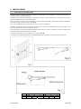 6
6
-
 7
7
-
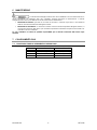 8
8
-
 9
9
-
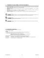 10
10
-
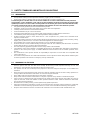 11
11
-
 12
12
-
 13
13
-
 14
14
-
 15
15
-
 16
16
-
 17
17
-
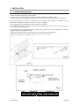 18
18
-
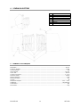 19
19
-
 20
20
-
 21
21
-
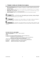 22
22
-
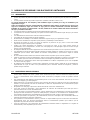 23
23
-
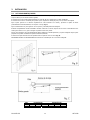 24
24
-
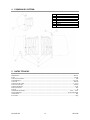 25
25
-
 26
26
-
 27
27
-
 28
28
-
 29
29
-
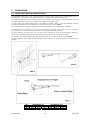 30
30
-
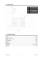 31
31
-
 32
32


Aprimatic 41035/001 Use And Maintenance Instructions
- Tipo
- Use And Maintenance Instructions
- Este manual también es adecuado para
en otros idiomas
- français: Aprimatic 41035/001
- italiano: Aprimatic 41035/001
- Deutsch: Aprimatic 41035/001
