
TOOLS REQUIRED TABLE OF CONTENTS
7/16" (≈11 mm)
3/8" (≈10 mm)
5/16" (≈8 mm) Wood Drill Bit
5/16" (≈8 mm) Masonry Drill Bit
Icon Legend...................................................4
Warnings & Notices.......................................5
Platform Construction..................................6
Truss Assembly...........................................11
Gable Assembly..........................................16
Door Assembly............................................18
Domed Skylight Assembly..........................27
Floor Assembly............................................31
Wall Assembly.............................................35
Truss Installation........................................40
Shelving Installation...................................47
Parts Identifi er.............................................49
Door & Gable Installation............................60
Trim Installation..........................................68
Roof Assembly............................................71
Window Installation....................................80
Pegboard Strip Installation........................87
Door Alignment...........................................89
Shed Anchoring..........................................92
Cleaning & Care.........................................99
Registration..............................................100
Warranty....................................................101
CONTACT LIFETIME CUSTOMER SERVICE:
Dial 1-800-225-3865 Live Chat: www.lifetime.com/customerservice/home
(click on “LIVE CHAT” tab)
QUESTIONS?
Model Number: 6415
Product ID:
BEFORE ASSEMBLY:
• Assemble on a level platform
• At least 3 people for setup recommended
Pour le français, voir la page 2. Para el español, ver la página 3.
ASSEMBLY INSTRUCTIONS
11' x 13.5'
STORAGE SHED
MODEL 6415
For Customer Service in mainland Europe:
E-mail: [email protected]

22
Légende des icônes......................................4
Avertissements et avis................................5
Assemblage de la plate-forme.....................6
Assemblage des fermes............................11
Assemblage des pignons..........................16
Assemblage des portes.............................18
Assemblage des lucarnes..........................27
Assemblage du plancher............................31
Assemblage des murs................................35
Instalación des fermes...............................40
Installation du rayonnage..........................47
Identifi cateur de pièces.............................49
Installation des portes...............................60
Installation des moulures..........................68
Assemblage du toit....................................71
Installation des fenêtres............................80
installation des organiseurs.......................87
Alignement des portes...............................89
L’ancrage de l’abri.....................................92
Nettoyage et entretien................................99
Enregistrement.......................................100
Garantie................................................102
OUTILS REQUIS SOMMAIRE
7/16 po (≈11 mm)
3/8 po (≈10 mm)
5/16 po (≈8 mm) Foret à boit
5/16 po (≈8 mm) Foret à maçonnerie
CONTACTER LES SERVICES À LA CLIENTÈLE DE LIFETIME® :
Composer le 1-800-225-3865 Chat en direct: www.lifetime.com/customerservice/home
(cliquer sur la languette « LIVE CHAT »)
QUESTIONS ?
N° de modèle : 6415
Référence du produit :
AVANT L’ASSEMBLAGE :
• Assembler sur une plat-forme nivelée
• Nous recommendons, au moins, 3 adultes pour
l’assemblage
For English, see page 1. Para el español, ver la página 3.
INSTRUCTIONS D’ASSEMBLAGE
ABRI EXTÉRIEUR DE
3,4 m x 4,1 m
MODÈLE n° 6415
Pour les services à la clientèle du continent européen :
É-mail : [email protected]

33
Leyenda de íconos.........................................4
Advertencias y avisos...................................5
Ensamblaje de la plataforma.....................6
Ensamblaje de las cerchas........................11
Ensamblaje de las fachadas.....................16
Ensamblaje de las puertas........................18
Ensamblaje de los tragaluces....................27
Ensamblaje del piso...................................31
Ensamblaje de los muros...........................35
Instalación de las cerchas........................40
Instalación de la estantería........................47
Identifi cador de piezas................................49
Instalación de las puertas.........................60
Instalación de las molduras......................68
Ensamblaje del tejado................................71
Instalación de las ventanas.......................80
Instalación de los organizadores......................87
Alineación de la puertas.............................89
Anclaje de la caseta...................................92
Limpieza y cuidado.....................................99
Registro................................................100
Garantía..............................................103
INSTRUMENTAL REQUERIDO ÍNDICE
7/16 in. (≈11 mm)
3/8 in. (≈10 mm)
5/16 in. (≈8 mm) Broca para madera
5/16 in. (≈8 mm) Broca de albañilería
PONERSE EN CONTACTO CON LOS SERVICIOS DE CLIENTES LIFETIME®:
Marcar al 1-800-225-3865 Chat en vivo: www.lifetime.com/customerservice/home
(cliquear en la lengüeta «LIVE CHAT»)
¿PREGUNTAS?
Número de modelo: 6415
ID del producto:
ANTES DE ENSAMBLAR:
• Ensamblar en una plataforma nivelada
• Recomendamos, al menos, 3 adultos para el
ensamblaje
For English, see page 1. Pour le français, voir la page 2.
INSTRUCCIONES DE ENSAMBLAJE
CASETA EXTERIOR DE
3,4 m x 4,1 m
MODELO n° 6415
Para el servicio a clientes en el continente europeo:
Correo electrónico: [email protected]

4
• Indicates the parts/no parts required for a section.
• Indique les pièces à utiliser/qu’aucone pièce n’est requise pour une section.
• Indica las piezas que se usarán/que no necesitan en una sección.
• Indicates special heed should be taken when reading.
• Indique qu’une attention spéciale doit être portée à la lecture.
• Indica que uno debe prestar atención al leer.
• Indicates the hardware to be used for a section.
• Indique la quincaillerie à utiliser pour une section.
• Indica los artículos de ferretería que se usarán para una sección.
• Indicates the tools to be used for a section.
• Indique les outils à utiliser pour une section.
• Indica las herramientas que se utilizarán para una sección.
• Indicates the number of adults required to perform a specifi c step, e.g., 2, 3, 4, etc.
• Indique le nombre d’adultes requis pour e ectuer une étape spécifi que, p. ex., 2, 3, 4, etc.
• Indica el número de adultos requeridos para realizar un paso específi co, p.ej., 2, 3, 4, etc.
• Indicates no hardware required for a specifi c page or section.
• Indique qu’aucun matériel n’est requis pour une page précise.
• Indica que no se necesitan los artículos de ferretería para una página específi ca.
• Indicates to use/not use an electric drill for a specifi c step.
• Indique quand utiliser une/que ne pas utiliser de perceuse électrique pour une étape précise.
• Indica la utilización de/que no utilizar un taladro eléctrico para un paso específi co.
ICON LEGEND / LÉGENDE DES ICÔNES / SIGNIFICADO DE LOS ÍCONOS
• These nuts are centerlock nuts. They are designed to be tight; therefore, they will be harder to tighten. Tighten until fl ush with the metal or plastic.
• Ces écrous sont des écrous de blocage central. Ils sont conçus pour être serrés; de ce fait, ils seront plus di ciles à resserrer. Serrer jusqu’à ce qu’ils
soient au ras du métal ou du plastique.
• Estas tuercas son tuercas de bloqueo central. Están diseñadas para estar apretadas; por lo tanto, serán más difíciles de apretar. Apriételas hasta que
estén al ras del metal o plástico.

5
English:
• Failure to follow these warnings may result in serious injury or property damage and will void warranty.
• To ensure safety, do not attempt to assemble this product without following the instructions carefully.
• Consult all local building codes to verify if the shed requires a building permit.
• Verify the foundation is completely level before assembling the shed.
• Be aware that plastic pieces can be damaged by overtightening the screws. To avoid damage, we strongly recommend the use of a drill
with a low torque setting. A #2 Phillips screwdriver may also be used.
• Three capable adults are required for assembly.
• All who participate in the assembly process should wear safety glasses throughout the assembly.
• If using a ladder during assembly, use extreme caution.
• In heavy snowfall areas, we recommend removing snow from the roof. Remove the snow from the roof when the depth of snow
equals the length of your hand.
• Do not use or store hot objects near the product.
• Proper and complete assembly are essential to reduce the risk of accident or injury.
• When drilling through metal, beware of burrs, shavings and other sharp edges.
• During and after assembly, do not slide or lift the shed by pushing up on the roof. Move the shed by pushing on the corner panels only.
• Failure to anchor the shed may result in property damage and/or personal injury. The last section, Shed Anchoring, in this manual shows the
hardware you will need to complete the anchoring. You can fi nd the hardware at your local hardware store.
• Most injuries are caused by misuse and/or not following instructions. Use caution when using this product.
Français :
• Ne pas suivre ces avertissements peut entraîner des blessures graves ou des dommages à la propriété et annulera la garantie.
• Afi n d’assurer la sécurité, ne pas tenter d’assembler ce produit sans suivre attentivement les instructions.
• Consulter tous les codes du bâtiment afi n de vérifi er si l’abri nécessite un permis de construire.
• Vérifi er que la fondation est complètement à niveau avant l’assemblage de l’abri.
• Ne pas oublier que les pièces de plastique peuvent être endommagées en serrant trop les vis. Afi n d’éviter les dommages, nous
recommandons fortement l’utilisation d’une perceuse à faible couple. Un tournevis cruciforme nº 2 peut aussi être utilisé.
• Trois adultes en bonne condition physique sont nécessaires pour l’assemblage.
• Tout ceux qui participent au processus de l’assemblage doivent porter des lunettes de sécurité tout au long de l’assemblage.
• Si une échelle est utilisée pour l’assemblage, il faut être extrêmement prudent.
• Dans les zones de fortes tombées de neige, il est recommandé de dégager le toit. Enlever la neige du toit quand la profondeur est égale
à la longueur de la main.
• Ne pas utiliser ou entreposer des objets très chauds près de ce produit.
• Un bon assemblage complet est nécessaire pour réduire le risque d’accident ou de blessure.
• En perçant le métal, faire attention aux bavures, copeaux et autre bords aiguisés.
• Pendant et après l’assemblage, ne pas faire glisser ou soulever l’abri en poussant le toit vers le haut. Déplacer l’abri en poussant les
panneaux muraux angulaires seulement.
• Si vous n’ancrez pas votre abri, des dommages à la propriété et/ou des blessures peuvent en résulter. La dernière section, Ancrage de l’abri, de
ce manuel indique les matériaux nécessaires pour l’ancrage. Les matériaux se trouvent dans la quincaillerie locale.
• La majorité des blessures sont causées par une mauvaise utilisation et/ou le non suivi des instructions. Étre prudent en utilisant ce produit.
Español:
• No seguir estas advertencias puede resultar en lesiones graves o daños a la propiedad y anulará la garantía.
• A fi n de garantizar la seguridad, no intentar ensamblar este producto sin seguir cuidadosamente las instrucciones.
• Consultar todos los códigos de construcción locales para verifi car si la casetao requiere un permiso de construcción.
• Verifi car que el concreto esté nivelado completamente antes de ensamblar la caseta.
• Tener en cuenta que las piezas de plástico pueden dañarse si los tornillos se aprietan de más. A fi n de evitar daños, lo exhortamos a que
use un taladro con función de torque bajo. También puede usarse un desatornillador Phillips no. 2.
• Se necesitan tres adultos para el ensamble.
• Todos los que participen en el proceso de ensamble debe usar anteojos de seguridad durante todo el ensamble.
• Si se usa una escalera durante el ensamblado, es preciso tener cuidado.
• En áreas de nevadas fuertes, recomendamos retirar la nieve del techo. Quitar la nieve del tejado cuando la profundidad de ella es igual
a la longitud de la mano.
• No usar ni guardar objetos calientes cerca del producto.
• El ensamblaje correcto y completo son esenciales para reducir el riesgo de accidente o lesión.
• Al perforar metal, tenga cuidado las rebabas, virutas y otros bordes afi lados.
• Durante y después del ensamblaje, no deslizar ni levantar la caseta para empujar en el tejado. Mover la caseta para empujar los paneles
murales angulares solamente.
• No anclar la caseta puede resultar en daños a la propiedad y/o en lesiones personales. La última sección, Anclaje de la caseta, en este
manual muestra el herraje necesaria para terminar el anclaje. Se encuentra el herraje en la ferretería local.
• La mayoría de las lesiones suceden a causa del mal uso y/o por no seguir las instrucciones. Tener precaución al usar este producto.
WARNINGS & NOTICES / AVERTISSEMENTS ET AVIS / ADVERTENCIAS Y AVISOS

6
PLATFORM CONSTRUCTION / CONSTRUCTION DE LA PLATE-FORME / CONSTRUCCIÓN DE LA
PLATAFORMA
1
• You must provide a platform on which to assemble your shed. Proper building permit documentation may be
required in your neighborhood. Consult all local building codes prior to assembling the shed. Before beginning
assembly, you must pour or construct a platform. There are two types:
• Concrete
• Wood Frame
Select the type, but know the surface must be leveled and fl at before installation. If the surface is not properly leveled and
fl at, the shed will not assemble correctly. Proper surface leveling will save you time in the long run, so please do not ignore
this step. We recommend a Concrete platform. It will be the most durable and long-lasting choice. The platform you choose must be built above
ground in order to avoid water pooling inside the shed. All lumber must be rated for outdoor use!
• Il faut construire une plate-forme sur laquelle vous devez assembler votre abri. Il est possible que votre quartier
exige une documentation visant les permis de construire. Consultez tous les codes du bâtiment locaux, ainsi
que les décrets des villes et comtés, pour vérifi er que la construction de l’abri extérieur n’exige pas un permis de
construire. Avant de commencer l’assemblage, il faut couler ou construire une plate-forme. Il y à deux styles :
• Béton
• Cadre à bois
Sélectionnez le style, mais sachez que la surface d’installation doit être de niveau et plate. Si la surface n’est pas
correctement de niveau et plate, l’assemblage de l’abri ne se fera pas correctement. Vous gagnerez du temps sur le long
terme grâce à une surface bien de niveau, ne négligez donc pas cette étape. Nous recommandons une plate-forme en Béton.
Ce choix sera le plus durable. La plate-forme que vous choisissez doit être construite au-dessus du sol afi n d’éviter l’accumulation d’eau à
l’intérieur de l’abri. Tous le bois d’oeuvre doit être approuvé pour l’usage à l’extérieur!
• Es preciso construir una plataforma sobre la cual usted debe ensamblar su caseta. Puede suceder que en su
vecindario se requiera la documentación apropiada de un permiso de construcción. Consulte todos los códigos
locales de construcción y los reglamentos de la ciudad y el municipio para asegurarse de que la construcción de
la caseta no requiere un permiso de construcción. Antes de comenzar el ensamble, es necesario verter o construir
una plataforma. Hay dos clases:
• Concreto
• Armazón de madera
Seleccione la clase, mas sepa que la superfi cie debe estar nivelada y plana antes de comenzar el ensamble. Si la superfi cie
no está nivelada y plana de manera adecuada, el cobertizo no podrá armarse correctamente. La nivelación de la superfi cie
le ahorrará tiempo de trabajo, por lo tanto, le pedimos que no ignore este paso. Recomendamos una plataforma hecho de concreto.
Será la elección más perdurable. La plataforma debe ser construida arriba del suelo para evitar el afl ujo de agua dentro de la caseta. ¡Toda la
madera debe estar clasifi cada para el uso externo!

77
X SECTION 1 (CONTINUED) / SECTION 1 (SUITE) / SECCIÓN 1 (CONTINUACIÓN) 1
1.5 yd3 (1,15 m3)
!
CONCRETE REQUIRED / BÉTON REQUIS / CONCRETO REQUERIDO
CONCRETE PLATFORM / PLATE-FORME EN BÉTON / PLATAFORMA DE CONCRETO
1.1
• The concrete should be approximately 4" (10,2 cm) thick. The actual dimensions of the shed, at its widest
and longest points, are 132" x 162" (3,35 m x 4,12 m). Ensure you select a site that will accommodate these
measurements. The fl oor dimensions are a bit smaller than those of the roof; therefore, you will need to builld a level surface of
123 1/2" x 153 1/2" (3,14 m 3,90 m).
• Le béton doit être un épaisseur de 10,2 cm (4 po). Les dimensions réelles de votre abri, aux points les plus large
et long, sont 3,35 m x 4,12 m (132 po x 162 po). Assurez-vous de sélectionner un site qui accommodera ces
dimensions. Les dimensions du plancher de votre abri sont plus petites que le toit; ensuite, il faut créer une surface nivelée de 3,14
m x 3,90 m (123 1/2 po x 153 1/2 po).
• El concreto debe tener, por lo menos, 10,2 cm (4 in.) de espesor. Las dimensiones reales de la caseta, a
sus puntos más ancho y largo, son 3,35 m x 4,12 m (132 in. x 162 in.). Asegúrese de seleccionar un sitio que
acomodará estas medidas. Las dimensiones del piso de la caseta son más pequeñas que el tejado; entonces, necesitará crear
una superfi cie nivelada de 3,14 m 3,90 m (123 1/2 in. x 153 1/2 in.).
162 in/po (4,12 m)
132 in/po (3,35 m)
123 1/2 in/po (3,14 m)
153 1/2 in/po (3,90 m)
4 in/po (10,2 cm)

88
X SECTION 1 (CONTINUED) / SECTION 1 (SUITE) / SECCIÓN 1 (CONTINUACIÓN) 1
WOOD PLATFORM / PLATE-FORME EN BOIS / PLATAFORMA DE MADERA
1.2
WOOD REQUIRED / BOIS REQUIS / MADERA REQUERIDA
RIDA
162 in/po (4,12 m)
132 in/po (3,35 m)
123 1/2 in/po (3,14 m)
153 1/2 in/po (3,90 m)

99
X SECTION 1 (CONTINUED) / SECTION 1 (SUITE) / SECCIÓN 1 (CONTINUACIÓN) 1
x36
!
x8
WOOD PLATFORM / PLATE-FORME EN BOIS / PLATAFORMA DE MADERA
1.2.1
TOOLS, PARTS, AND HARDWARE REQUIRED / OUTILS, PIÈCES, ET QUINCAILLERIE REQUIS / INSTRUMENTAL, PIEZAS, Y HERRAJE
REQUERIDOS
1.2.2
Start Here / Comence aquí /
Commencez ici
2 in/po x 4 in/po x 153 1/2 in/po (3,90 m) (x2)
2 in/po x 4 in/po x 120 1/2 in/po (3,06 m) (x11)
16d 3 1/2 in/po (16d x 8,892 cm) (x44)
• Ensure all lumber is treated and approved for outdoor use. Build frame to 123 1/2" x 153 1/2" (3,14 m x 3,90
m) (outside dimensions).
• Vérifi ez que votre bois d’œuvre à été traité et approuvé pour l’utilisation à l’extérieur. Contruisez un cadre de
3,14 m x 3,90 m (123 1/2 po x 153 1/2 po) (dimensions extérieures).
• Asegure que use madera tratada y aprobada para el uso externo. Construya el armazón a 3,14 m x 3,90 m
(123 1/2 in. x 153 1/2 in.) (dimensiones exteriores).
123 1/2 in/po (3,14 m)
120 1/2 in/po (3,06 m)
153 1/2 in/po (3,90 m)
• Nail the fi rst inner stud 16" (40,1 cm) from the front corner. Then nail the rest 16" (40,1 cm) on center.
• Clouez le premier montant intérieur 40,1 cm (16 po) de l’angle avant. Ensuite, clouez les montants intérieurs
restants 40,1 cm (16”) de centre à centre du montant intérieur précédent.
• Clave el primer montante interior 40,1 cm (16 in.) del ángulo delantero. Entonces, clave los montantes
interiores restantes 40,1 cm (16 in.) a partir del centro del montante interior anterior.
16"
40,6 cm
16"
40,6 cm
16"
40,6 cm
16"
40,6 cm
16"
40,6 cm
16"
40,6 cm
16"
40,6 cm
16"
40,6 cm
16"
40,6 cm
16"
40,6 cm

1010
X SECTION 1 (CONTINUED) / SECTION 1 (SUITE) / SECCIÓN 1 (CONTINUACIÓN) 1
x76
!A = B
Drainage Holes
Agujeros para canalización
Trous de drainage
TOOLS, PARTS, AND HARDWARE REQUIRED / OUTILS, PIÈCES, ET QUINCAILLERIE REQUIS / INSTRUMENTAL, PIEZAS, Y HERRAJE
REQUERIDOS
• Square the frame, measuring from corner to corner. Measurement A & B should be about the same length.
• Carrez le cadre en mesurant d’angle à angle. La mesure « A » et « B » doivent être à peu près la même longeur.
• Cuadre el armazón mediendo de esquina a esquina. La medida «A» y «B» deben ser approximadamente el mismo
largo.
1.2.3
• Using nails, fasten the plywood to the frame. Then, drill 5/16" (8 mm) holes for drainage.
• Usando unos clavos, sujete el contrachapado al armazón. Entonces, taladre agujeros de 8 mm para el drenaje.
• En utilisant des clous, attachez bien le contreplaqué au cadre. Ensuite, percez des trous de 8 mm pour le
drainage.
1.2.4
8d 2 1/2 in/po
(8d x 6,35 cm) (x76)
48 in/po x 96 in/po x 3/4 in/po
1,22 m x 2,44 m x 19 mm (x3)
27 1/2 in/po x 96 in/po x 3/4 in/po
(69,9 cm x 2,44 m x 19 mm) (x1)
27 1/2 in/po x 57 1/2 in/po x 3/4 in/po
(69,9 cm x 1,46 m x 19 mm) (x1)
9 1/2 in/po x 96 in/po x 3/4 in/po
(24,1 cm x 2,44 m x 19 mm) (x1)
A
B
27 1/2 in/po x 57 1/2 in/po x 3/4 in/po
(69,9 cm x 1,46 m x 19 mm) (x1)
9 1/2 in/po x 96 in/po x 3/4 in/po (x1)
24,1 cm x 2,44 m x 19 mm) (x1)
27 1/2 in/po x 96 in/po x 3/4 in/po
(69,9 cm x 2,44 m x 19 mm) (x1)
48 in/po x 96 in/po x 3/4 in/po
(1,22 m x 2,44 m x 19 mm) (x3)
x60!
!
!

11
TRUSS ASSEMBLY / ASSEMBLAGE DES FERMES / ENSAMBLAJE DE LAS CERCHAS
2
71 11/16”
71 11/16 in/po (1,82 m)
79 1/2”
79 1/2 in/po (2,02 m)
79 1/2”
79 1/2 in/po (2,02 m)
AFP (x10)
AIP (x5) AHT (x10)
AFH (x10)
AFG (x5)
AFQ (x10)
AAK (x50)
ADJ (x50)
20 1/8”
20 1/8 in/po (51 cm)
DTO
7/16 in/po (11 mm) (x2)
Metal Parts / Pièces en métal / Piezas de metal
TOOLS REQUIRED / OUTILS REQUIS / INSTRUMENTAL REQUERIDO
PARTS REQUIRED / PIEZAS REQUERIDAS / PIÈCES REQUISES
HARDWARE REQUIRED / QUINCAILLERIE REQUISE / HERRAJE REQUERIDO

1212
TOOLS AND HARDWARE REQUIRED / OUTILS ET QUINCAILLERIE REQUIS / INSTRUMENTAL Y HERRAJE REQUERIDOS
X SECTION 2 (CONTINUED) / SECTION 2 (SUITE) / SECCIÓN 2 (CONTINUACIÓN)
AIP (x5)
AFH
AFH
AIP
• Place a Truss Connector (AIP) down inside the ends of two Truss Gutter Channels (AFH) as shown.
• Insérez un connecteur de fermes (AIP) dans les extrémités de deux canaux de gouttière (AFH) comme illustré.
• Coloque un connector de canales (AIP) en los extremos de dos canalones de la cercha (AFH) como se muestra.
2.1

1313
TOOLS AND HARDWARE REQUIRED / OUTILS ET QUINCAILLERIE REQUIS / INSTRUMENTAL Y HERRAJE REQUERIDOS
X SECTION 2 (CONTINUED) / SECTION 2 (SUITE) / SECCIÓN 2 (CONTINUACIÓN)
AAK (x10)
ADJ (x10)
7/16 in/po (x2)
11 mm (x2)
AAK
ADJ
AFP
AFP
• Insert two (2) Bolts (AAK) through the fi rst Vertical Truss Brace (AFP), the holes in the Truss Gutter Channels, over the
Truss Connector, and out through the Truss Gutter Channels and second Vertical Truss Support (AFP). Secure with two
Cap Nuts (ADJ). Do not overtighten the Nuts.
• Insérez deux (2) boulons (AAK) à travers le premier support vertical (AFP), les trous dans les canaux de gouttière, over
le connecteur de fermes, et à travers les canaux et le deuxième support vertical (AFP). Attachez-les bien à l’aide de
deux écrous borgnes (ADJ). Ne pas trop serrer.
• Inserte dos (2) pernos (AAK) a través del primer soporte vertical (AFP), los agujeros en los canalones de la cercha,
encima del conector de cerchas, y a través de los canalones de la cercha y el segundo soporte vertical (AFP).
Sujételos con dos tuercas ciegas (ADJ). No apriete demasiado las tuercas.
2.2

1414
TOOLS AND HARDWARE REQUIRED / OUTILS ET QUINCAILLERIE REQUIS / INSTRUMENTAL Y HERRAJE REQUERIDOS
X SECTION 2 (CONTINUED) / SECTION 2 (SUITE) / SECCIÓN 2 (CONTINUACIÓN)
AAK (x20)
ADJ (x20)
7/16 in/po (x2)
11 mm (x2)
AFH
AAK
ADJ
AFG
AFG
AFP (x2)
AAK
ADJ
ADJ
AAK
• Secure a Horizontal Truss Brace (AFG) to the Channels and the Vertical Truss Braces using four (4) Bolts (AAK) and Cap
Nuts (ADJ). Do not overtighten the Nuts.
• Attachez bien un support horizontal (AFG) aux canaux et aux supports verticaux à l’aide de quatre (4) boulons (AAK) et
écrous borgnes (ADJ). Ne pas trop serrer.
• Sujete un soporte horizontal (AFG) a los canalones y los soportes verticales usando cuatro (4) pernos (AAK) y tuercas
ciegas (ADJ). No apriete demasiado las tuercas.
AFG
2.3

1515
TOOLS AND HARDWARE REQUIRED / OUTILS ET QUINCAILLERIE REQUIS / INSTRUMENTAL Y HERRAJE REQUERIDOS
X SECTION 2 (CONTINUED) / SECTION 2 (SUITE) / SECCIÓN 2 (CONTINUACIÓN)
AAK (x20)
ADJ (x20)
7/16 in/po (x2)
11 mm (x2)
AFQ
AFQ
AAK
ADJ
AFH
AFQ
• Attach a Wall Support Channel (AFQ) to each end of the Truss Assembly using
the hardware provided. Do not overtighten.
• Attachez un canal de support pour le mur (AFQ) à chaque extrémité de
l’ensemble de la ferme à l’aide de la quincaillerie incluse. Ne pas trop serrer.
• Sujete un canal de soporte para el muro (AFQ) a cada extremo del conjunto de
la cercha usando el herraje incluido. No apriete demasiado.
ADJ
AFQ
AHT
AAK
• Attach a Floor Bracket (AHT) to the bottom of each Wall Support Channel. Do not overtighten. Repeat this section four times.
• Attachez un support de la ferme (AHT) à l’extrémité inférieure de chaque canal de support à mur. Ne pas trop serrer.
Répétez cette section quatre fois.
• Sujete un soporte para la cercha (AHT) al extremo inferior de cada canal de soporte para el muro. No apriete demasiado.
Repita esta sección cuatro veces.
AHT (x10)
2.4
2.5

16
GABLE ASSEMBLY / ASSEMBLAGE DES PIGNONS / ENSAMBLAJE DE LAS FACHADAS
3
ADW (x10)
AEE (x10)
AGP (x2) AIQ (x2)
ADZ (x8)
AGI (x2)
AGH (x2)
DTP
HARDWARE REQUIRED / QUINCAILLERIE REQUISE / HERRAJE REQUERIDO
Plastic Parts / Pièces en plastique / Piezas de plástico
TOOLS REQUIRED / OUTILS REQUIS / INSTRUMENTAL REQUERIDO
PARTS REQUIRED / PIÈCES REQUISES / PIEZAS REQUERIDAS

1717
TOOLS AND HARDWARE REQUIRED / OUTILS ET QUINCAILLERIE REQUIS / INSTRUMENTAL Y HERRAJE REQUERIDOS
X SECTION 3 (CONTINUED) / SECTION 3 (SUITE) / SECCIÓN 3 (CONTINUACIÓN)
ADZ ADZ
ADZ ADZ
AGH
AGI
ADZ (x8) ADW (x10)
AEE (x10)
AGP
AIQ
ADW
AEE
• Set the edge of Gable Side A (AGH) over the edge of Gable Side B (AGI), and align the four holes.
• Mettre le bord du pignon A (AGH) sur le bord du pignon B (AGI), et aligner les quatre trous.
• Colocar el borde de la fachada A (AGH) encima del borde de la fachada B (AGI), y alinear los cuatro agujeros.
• Place a Screen (AIQ) over a Vent (AGP). Set the
Gable Assembly over the Screen and Vent so the
holes in the Gable align with those in the Vent.
Secure with the hardware included. Repeat these
steps for the second Gable.
• Mettre un mosquitaire (AIQ) sur un évent (AGP).
Mettre le pignon sur le mosquitaire et l’évent pour
que les trous dans le pignon s’alignent avec ceux
de l’évent. Attacher l’évent au pignon à l’aide des
accessoires inclus. Répéter ces étapes pour le deuxième
pignon.
• Colocar un mosquitero (AIQ) encima de una ventila
(AGP). Colocar la fachada encima del mosquitero
y la ventila para que los agujeros en la fachada se
alineen con ellos en la ventila. Sujetar la la ventila
a la fachada usando el herraje incluido. Repitir estos
pasos para la segunda fachada.
• Secure Gable Side A to Gable Side B using the
hardware included.
• Attacher le pignon A au pignon B à l’aide de la
quincaillerie incluse.
• Sujetar la fachada A a la fachada B usando el
herraje incluido.
3.2
3.1
3.3

18
LEFT DOOR ASSEMBLY / ASSEMBLAGE DE LA PORTE GAUCHE / ENSAMBLAJE DE LA PUERTA IZQUIERDA
4
77 13/16”
77 13/16 in/po (1,98 m)
AHM (x2)
AGO (x1)
ADW (x3) AEE (x3)
ACH (x2) ADJ (x2)
ADZ (x9)
AHZ (x1) AIB (x1) AIA (x1)
BKB
7/16 in/po (11 mm)
Metal Parts / Pièces en métal / Piezas de metal
Plastic Parts / Pièces en plastique / Piezas de plástico
TOOLS REQUIRED / OUTILS REQUIS / INSTRUMENTAL REQUERIDO
PARTS REQUIRED / PIÈCES REQUISES / PIEZAS REQUERIDAS
HARDWARE REQUIRED / QUINCAILLERIE REQUISE / HERRAJE REQUERIDO
AFC (x1)
18 1/2”
18 1/2 in/po (47 cm)
AFB (x3)
EGL

1919
TOOLS AND HARDWARE REQUIRED / OUTILS ET QUINCAILLERIE REQUIS / INSTRUMENTAL Y HERRAJE REQUERIDOS
X SECTION 4 (CONTINUED) / SECTION 4 (SUITE) / SECCIÓN 4 (CONTINUACIÓN)
AHM (x2)
AFC
AGO
AHM
AHM
• Set the Deadbolts (AHM) down into the recesses at the top and bottom of the Door. Then, slide the Door End Channel
(AFC) over the edge of the Door and the bottom of the Deadbolts as shown.
• Mettez les loquets à pêne dormant (AHM) dans les encoches aux parties supérieure et inférieure de la porte. Ensuite,
faites glisser le canal pour l’éxtrémité de la porte (AFC) sur le bord de la porte et les parties inférieures des loquets à
pêne dormant comme illustré.
• Ponga los cerrojos (AHM) en las muescas a las partes superior et inferior de la puerta. Entonces, deslice el canal
para el borde de la puerta (AFC) sobre el borde de la puerta y las partes inferiores de los cerrojos come se muestra.
4.1

2020
TOOLS AND HARDWARE REQUIRED / OUTILS ET QUINCAILLERIE REQUIS / INSTRUMENTAL Y HERRAJE REQUERIDOS
X SECTION 4 (CONTINUED) / SECTION 4 (SUITE) / SECCIÓN 4 (CONTINUACIÓN)
ADZ ADZ ADZ
ADZ
ADZ
ADZ
ADZ
ADZ
ADZ
AFB
AFB
AFB
• Note: The Deadbolts are used for locking the door. They may not move
freely at fi rst. You may need to tap them up and down a few times with a
rubber mallet to work them in.
• Note : On utilise les loquets pour fermer la porte. Au debut, il se peut
que les Loquets ne se déplacent librement. Vous devrez peut-être les taper
légèrement à l’aide d’un maillet en caoutchouc pour les desserrer.
• Nota: Se usan los cerrojos para cerrar la puerta. Al principio, pueden que
no se desplacen libremente. Puede que necesite darlos unos golpecitos
con un mazo de goma para afl ojarlos.
• Attach three (3) Door Braces (AFB) to the
back of the Left Door.
• Attachez trois (3) supports à la porte (AFB) au
côté arrière de la porte gauche.
• Sujete tres (3) soportes para la puerta (AFB) a
la cara trasera de la puerta izquierda.
4.2
ADZ (x9)
LIFETIME©

2121
TOOLS AND HARDWARE REQUIRED / OUTILS ET QUINCAILLERIE REQUIS / INSTRUMENTAL Y HERRAJE REQUERIDOS
X SECTION 4 (CONTINUED) / SECTION 4 (SUITE) / SECCIÓN 4 (CONTINUACIÓN)
ADW ADW
ADW
AHZ
AEE
AEE
AEE
ADJ
ACH
AIA
ADW (x3)
AEE (x3)
ACH (x2)
ADJ (x2)
AIA (x1) AHZ (x1)
7/16 in/po (x2)
11 mm (x2)
• Secure the Left Door Latch (AIA) to the Left Door using
the hardware provided. Do not overtighten.
• Bien attachez le loquet gauche (AIA) à la porte gauche
à l’aide de la quincaillerie incluse. Ne pas trop serrer.
• Sujete el pestillo de cierre izquierdo (AIA) a la puerta iz-
quierda usando el herraje incluido. No apriete demasiado.
• Secure the Left Door Handle (AHZ) to the Left Door using the hardware provided. Do not overtighten.
• Attachez bien la poignée (AHZ) à la porte gauche à l’aide de la quincaillerie incluse. Ne pas trop serrer.
• Sujete el picaporte izquierdo (AHZ) a la puerta izquierda usando el herraje incluido. No apriete demasiado.
4.3 4.4
4.5
AIB
• Slide the Strike Plate (AIB) over the Door End
Channel, and align the holes.
• Faites glisser la gâche (AIB) sur le canal au bord
de la porte, et alignez les trous.
• Deslice la placa de refuerzo (AIB) sobre el canal
para el borde de la puerta, y alinee los agujeros.
AIB (x1)

22
RIGHT DOOR ASSEMBLY / ASSEMBLAGE DE LA PORTE DROITE / ENSAMBLAJE DE LA PUERTA DERECHA
5
AGZ (x1)
AIK (x1)
AIO (x1)
AEE (x3)
ADZ (x9)
AHW (x1)
ADW (x4)
ACI (x2)
ADB (x2)
AAB (x2)
AEB (x2)
AHY (x1)
AHV (x1) AHX (x1)
AIL (x1)
77 13/16”
77 13/16 in/po (1,98 m)
18 1/2”
18 1/2 in/po (47 cm)
AFB (x3)
BKC
7/16 in/po (11 mm)
Metal Parts / Pièces en métal /Piezas de metal
Plastic Parts / Pièces en plastique / Piezas de plástico
TOOLS REQUIRED / OUTILS REQUIS / INSTRUMENTAL REQUERIDO
PARTS REQUIRED / PIÈCES REQUISES / PIEZAS REQUERIDAS
HARDWARE REQUIRED / QUINCAILLERIE REQUISE / HERRAJE REQUERIDO
AFC (x1)
EGL

2323
TOOLS AND HARDWARE REQUIRED / OUTILS ET QUINCAILLERIE REQUIS / INSTRUMENTAL Y HERRAJE REQUERIDOS
X SECTION 5 (CONTINUED) / SECTION 5 (SUITE) / SECCIÓN 5 (CONTINUACIÓN)
• Slide the Door End Channel (AFC) over the edge of the Door as shown.
• Faites glisser le canal pour le bord de la porte (AFC) sur le bord de la porte comme illustré.
• Deslice el canal para el borde de la puerta (AFC) sobre el borde de la puerta come se muestra.
AFC
AFC
AGZ
5.1

2424
TOOLS AND HARDWARE REQUIRED / OUTILS ET QUINCAILLERIE REQUIS / INSTRUMENTAL Y HERRAJE REQUERIDOS
X SECTION 5 (CONTINUED) / SECTION 5 (SUITE) / SECCIÓN 5 (CONTINUACIÓN)
• Slide the Thumb Lever (AIO) down into the grooves in the Door Handle (AIK) until the nubs fi t into the holes.
• Faites glisser le levier poussoir (AIO) dans les rainures de la poignée (AIK) jusqu’à ce que les petites bosses se fi xent
dans les trous.
• Deslice la palanca de pulgar (AIO) en las ranuras del picaporte (AIK) hasta que los nudos se encajen en los agujeros.
AFB
AFB
AFB
ADZ
ADZ
ADZ
ADZ
ADZ
ADZ
ADZ
ADZ
ADZ
AIK
AIO
• Attach three (3) Door Braces (AFB) to the back of the Right Door.
• Attachez trois (3) supports de la porte (AFB) au côté arrière de la porte droite.
• Sujete tres (3) soportes de la puerta (AFB) a la cara trasera de la puerta derecha.
5.2
5.3
ADZ (9)
AIK (x1)
AIO (x1)

2525
TOOLS AND HARDWARE REQUIRED / OUTILS ET QUINCAILLERIE REQUIS / INSTRUMENTAL Y HERRAJE REQUERIDOS
X SECTION 5 (CONTINUED) / SECTION 5 (SUITE) / SECCIÓN 5 (CONTINUACIÓN)
AHX
AIL
AAB
AAB
ACI
ACI
ADB
ADB
AEB
AEB
AHV (x1)
AHX (x1)
ACI (x2) ADB (x2)
AAB (x2) AEB (x2)
AIL (x1)
AEE (x3) ADW (x3)
AHV
7/16 in/po (x2)
11 mm (x2)
• Insert the Thumb Lever through the slot, and attach the Handle
using the hardware provided.
• Insérez le levier poussoir à travers la fente, et attachez la poignée
à l’aide de la quincaillerie incluse.
• Inserte la palanca de pulgar a través de la ranura, y sujete el
picaporte usando el herraje incluido.
• Attach the Locking Hardware using the hardware provided. The arm of the
Latch rests on top of the Thumb Lever.
• Attachez les accessoires de verrouillage à l’aide de la quincaillerie
incluse. Le bras du Loquet doit rester sur le levier poussoir.
• Sujete los accesorios de cierre usando el herraje incluido. El brazo del
pestillo se queda sobre la palanca de pulgar.
ADW
ADW
ADW
AEE
AEE
AEE
5.4
5.5

2626
TOOLS AND HARDWARE REQUIRED / OUTILS ET QUINCAILLERIE REQUIS / INSTRUMENTAL Y HERRAJE REQUERIDOS
X SECTION 5 (CONTINUED) / SECTION 5 (SUITE) / SECCIÓN 5 (CONTINUACIÓN)
AHW (x1)
ADW (x1)
ADW
AHW
AIO
2
1
• Attach the Thumb Lever Support (AHW) to the Thumb Lever (AIO) using a Screw (ADW). The edge of the Support goes underneath
the Thumb Lever.
• Attachez le support du levier poussoir (AHW) au levier poussoir (AIO) à l’aide d’une vis (ADW). Le bord du support se fi xe sous
le levier poussoir.
• Sujete el soporte de la palanca de pulgar (AHW) a la palanca de pulgar (AIO) usando un tornillo (ADW). El borde del soporte se
fi ja debajo la palanca de pulgar.
The Edge of the Support / Le bord du levier poussoir /
El borde de la palanca de pulgar
AHY (x1)
• Attach the Spring (AHY) to the Latch (AHV) and Latch Cover Plate (AHX) as shown.
• Attachez le ressort (AHY) au loquet (AHV) et la plaque protectrice du loquet (AHX) comme illustré.
• Sujete el resorte (AHY) al pestillo (AHV) y a la placa cubrepestillo (AHX) como se muestra.
AHV
AHX
AHY
5.6
5.7

27
DOMED SKYLIGHT ASSEMBLY / ASSEMBLAGE DES LUCARNES EN FORME DE DÔME / ENSAMBLAJE DE LOS
TRAGALUCES EN FORMA DE CÚPULA
6
ADK (x24) AEE (x48)
EFA (x24)
AHB (x2)
AGB (x2)
AHI (x2)
BEC
2
3/8 in/po (10 mm)
Plastic Parts / Pièces en plastique / Piezas de plástico
TOOLS REQUIRED / OUTILS REQUIS / INSTRUMENTAL REQUERIDO
PARTS REQUIRED / PIÈCES REQUISES / PIEZAS REQUERIDAS
HARDWARE REQUIRED / HERRAJE REQUERIDO / QUINCAILLERIE REQUISE

2828
TOOLS AND HARDWARE REQUIRED / OUTILS ET QUINCAILLERIE REQUIS / INSTRUMENTAL Y HERRAJE REQUERIDOS
X SECTION 6 (CONTINUED) / SECTION 6 (SUITE) / SECCIÓN 6 (CONTINUACIÓN)
AHB
AHI
• Remove any excess plastic from the holes along the opening.
• Enlevez de l’excès de plastique des trous le long de l’ouverture.
• Retire cualquier plástico en exceso de los agujeros a lo largo de la abertura.
• Lay Butyl Tape (AHI) along the groove running along the top edge of the opening of the Panel. Cut the Butyl Tape.
• Mettez le ruban butylique (AHI) le long de la rainure qui s’étend le long du bord supérieur de la couverture du
panneau. Coupez le ruban butilique.
• Coloque la cinta de butilo (AHI) a lo largo de la ranura que corre a lo largo del borde superior de la abertura del
panel. Corte la cinta de butilo.
6.1
6.2
AHI (x2)

2929
TOOLS AND HARDWARE REQUIRED / OUTILS ET QUINCAILLERIE REQUIS / INSTRUMENTAL Y HERRAJE REQUERIDOS
X SECTION 6 (CONTINUED) / SECTION 6 (SUITE) / SECCIÓN 6 (CONTINUACIÓN)
AHI
AHI
6.3 6.4
6.6
6.5
• Do not remove any paper backing yet! Lay Butyl Tape
(AHI) along the groove running along the right
edge of the opening of the Panel. Cut the Tape.
• ¡No retire todavía el papel protector! Coloque la cinta
de butilo (AHI) a lo largo de la ranura que corre a lo
largo del borde derecho de la abertura del panel.
Corte la cinta.
• Ne pas retirer encore le papier protecteur ! Mettez
le ruban butylique (AHI) le long de la rainure qui
s’étend le long du bord droit de la couverture du
panneau. Coupez le ruban.
• Do not remove any paper backing yet! Lay Butyl Tape
(AHI) along the groove running along the bottom
edge of the opening of the Panel. Cut the Tape.
• Ne pas retirer encore le papier protecteur ! Mettez le
ruban butylique (AHI) le long de la rainure qui s’étend
le long du bord inférieur de la couverture du
panneau. Coupez le ruban.
• ¡No retire todavía el papel protector! Coloque la cinta
de butilo (AHI) a lo largo de la ranura que corre a lo
largo del borde inferior de la abertura del Panel.
Corte la cinta.
• Smooth out the Tape to remove any bubbles. Remove
the paper backing. Using a plain screwdriver, poke
holes through the Butyl Tape and through the holes
in the Roof Panel. The holes in the Roof Panel must
remain square.
• Lissez le ruban pour éliminer des bulles. Enlevez la
pellicule protectrice. Mettez un tournevis plat dans
le ruban butylique et à travers les trous carrés dans
le panneau de toit. Les trous dans le panneau de
toit doivent rester carrés.
• Alise la cinta para eliminar cualquier burbuja. Reitre el
papel protector. Mete un destornillador de punta
plana a través de la cinta butilo y los agujeros
cuadrados en el panel de tejado. Los agujeros en el
panel de tejado deben
quedarse cuadrados.
• Do not remove any paper backing yet! Lay Butyl Tape
(AHI) along the groove running along the left edge of
the opening of the Panel. Cut the Tape.
• Ne pas retirer encore le papier protecteur ! Mettez
le ruban butylique (AHI) le long de la rainure qui
s’étend le long du bord gauche de la couverture du
panneau. Coupez le ruban.
• ¡No retire todavía el papel protector! Coloque la cinta
de butilo (AHI) a lo largo de la ranura que corre a lo
largo del borde izquierdo de la abertura del panel.
Corte la cinta.
AHI
AHI (x2)

3030
TOOLS AND HARDWARE REQUIRED / OUTILS ET QUINCAILLERIE REQUIS / INSTRUMENTAL Y HERRAJE REQUERIDOS
X SECTION 6 (CONTINUED) / SECTION 6 (SUITE) / SECCIÓN 6 (CONTINUACIÓN)
• Align the holes in the Skylight with those in the
Panel, and lay the Skylight on the Panel. Press the
Skylight onto the Butyl Tape to remove any bubbles.
• Alignez les trous dans la lucarne avec ceux dans
le panneau, et mettez la lucarne sur le panneau.
Poussez la lucarne contre le ruban pour éliminer
des bulles.
• Alinee los agujeros en el tragaluz con ellos en el
panel, y coloque el tragaluz en el panel. Empuje el
tragaluz contra la cinta para eliminar las burbujas.
AGB
AGB
EFA
EFA
EFA
ADK
ADK
AEE (x2) AEE (x2)
3/8 in/po
(10 mm)
ADK (x24)
AEE (x48)
EFA (x24)
• Secure the Skylight to the Panel using the
hardware provided.
• Attachez la lucarne au panneau à l’aide de la
quincaillerie incluse.
• Sujete el tragaluz al panel usando el herraje
incluido.
• Repeat this section for the second Domed
Skylight.
• Répétez cette section pour la deuxième lucarne
en forme de dôme.
• Repita esta sección para el segundo tragaluz en
forma de cúpula.
6.7
6.9
6.8
6.10
• Remove the protective fi lm from both sides of
the Skylight (AGB).
• Soulevez la pellicule protectrice des deux côtés
de la lucarne (AGB).
• Retire la capa protectora de los dos caras del
tragaluz (AGB).

31
FLOOR ASSEMBLY / ASSEMBLAGE DU PLANCHER / ENSAMBLAJE DEL PISO
7
AGJ (x8)
AGS (x2) AGT (x2)
Plastic Parts / Pièces en plastique / Piezas de plástico
Hardware Bag / Sac de quincaillerie / Bolsa de herraje
TOOLS REQUIRED / OUTILS REQUIS / INSTRUMENTAL REQUERIDO
PARTS REQUIRED / PIÈCES REQUISES / PIEZAS REQUERIDAS
HARDWARE REQUIRED / HERRAJE REQUERIDO / QUINCAILLERIE REQUISE
BQC (x50) ADC (x1)
(x1)
(x1)
FOE
Note: These Screws do not anchor the Floor; they only hold the Panels together.
Note : Ces vis n’ancrent pas le plancher ; ils ne servent que pour attacher les panneaux les uns aux autres.
Nota: Estos tornillos no anclan el piso; sirven sólo para sujetar los paneles los unos a los otros.
!

3232
TOOLS AND HARDWARE REQUIRED / OUTILS ET QUINCAILLERIE REQUIS / INSTRUMENTAL Y HERRAJE REQUERIDOS
X SECTION 7 (CONTINUED) / SECTION 7 (SUITE) / SECCIÓN 7 (CONTINUACIÓN)
45°
AGS
AGT
AGJ
AGJ
45°
45° AGJ
AGJ
• Hold an Outer Floor Panel (AGS) at an angle and slide the tabs along the edge underneath the other Outer Floor Panel
(AGT). The tabs interlock. Lay Panel down fl at.
• Posez un panneau de plancher extérieur (AGS) à un angle et glissez les languettes le long du bord au-dessus de l’autre
panneau de plancher extérieur (AGT). Les languettes s’enclenchent les uns les autres. Étendez-le par terre.
• Coloque un panel de piso exterior (AGS) a un ángulo y deslice las lenguetas a lo largo del borde debajo el otro panel
de piso exterior (AGT). Las lengüetas se entrelazan las unas con las otras. Aplane el panel.
• Join two Inner Floor Panels (AGJ). Then, slide the tabs along the edge underneath the fi rst
two Outer Floor Panels. The tabs interlock. Lay the Panels down fl at.
• Attachez deux panneaux de plancher intérieurs (AGJ). Ensuite, glissez les languettes le
long du bord au-dessus des autres panneaux de plancher extérieurs. Les languettes
s’enclenchent les uns les autres. Étendez-les par terre.
• Junte dos paneles de piso interiores (AGJ). Entonces, deslice las lenguetas a lo largo del
borde debajo los otros paneles de piso exteriores. Las lengüetas se entrelazan las unas
con las otras. Aplane los paneles.
7.1
7.2

3333
TOOLS AND HARDWARE REQUIRED / OUTILS ET QUINCAILLERIE REQUIS / INSTRUMENTAL Y HERRAJE REQUERIDOS
X SECTION 7 (CONTINUED) / SECTION 7 (SUITE) / SECCIÓN 7 (CONTINUACIÓN)
• Continue joining two Inner Floor Panels (AGJ) and connecting them to the previous Panals. Lay the Panels down fl at.
• Continuez à assembler deux panneaux de plancher intérieurs (AGJ) et à attacher les panneaux aux panneaux
précédents. Étendez-les par terre.
• Continúe a juntar dos paneles de piso interiores (AGJ) y a conectarlo a los paneles anteriores. Aplane los paneles.
• Repeat the fi rst step to join two more Outer Floor Panels (AGS & AGT). Then, slide the
tabs along the edge underneath the last two Inner Floor Panels. Lay the Panels down
fl at.
• Répétez la première étape pour assembler deux plus panneaux de plancher extérieurs
(AGS et AGT). Ensuite, glissez les languettes le long du bord au-dessus des autres
panneaux de plancher extérieurs. Étendez-les par terre.
• Repita el primer paso para unir dos más paneles de piso exteriores (AGS y AGT).
Entonces, deslice las lenguetas a lo largo del borde debajo los otros paneles de piso
exteriores. Aplane los paneles.
AGJ
AGJ
AGJ
AGJ
7.3
7.4
AGJ AGJ
AGT
AGS

3434
TOOLS AND HARDWARE REQUIRED / OUTILS ET QUINCAILLERIE REQUIS / INSTRUMENTAL Y HERRAJE REQUERIDOS
X SECTION 7 (CONTINUED) / SECTION 7 (SUITE) / SECCIÓN 7 (CONTINUACIÓN)
• Use a screwdriver or drill to connect the Panels together using the screws (BQC) provided: (1) four Screws in the divots
at each seam intersection, (2) one Screw in the divot near each end of the center seam, and (3) one Screw in the divot
near each seam along the sides of the Floor. Do not overtighten.
• Employer un tournevis or perceuse éléctrique pour fi xer les panneaux les uns les autres en utilisant les vis (BQC) inclues
: (1) quatre vis dans les marques aux intersections de chaque jointure, (2) une vis près chaque extrémité de la jointure
centrale, et (3) une vis dans la marque près chaque jointure le long des bords latéraux du plancher. Ne pas trop serrer.
• Usar un destornillador o taladro eléctrico para fi jar los paneles usando los tornillos (BQC) incluidos: (1) cuatro tornillos en
las marcas a los cruces de cada línea, (2) un tornillo en la marca cerca cada extremo de la línea central, y (3) un tornillo
en la marca cerca cada línea a lo largo de los bordes laterales del piso. No apretar demasiado.
7.5
BQC (x32)
(1)
(2)
(3)
ADC (x1)
Note: These Screws do not anchor the Floor; they only hold the Panels together.
Note : Ces vis n’ancrent pas le plancher ; ils ne servent que pour attacher les panneaux les uns aux autres.
Nota: Estos tornillos no anclan el piso; sirven sólo para sujetar los paneles los unos a los otros.
!

35
WALL ASSEMBLY / ASSEMBLAGE DES MURS / ENSAMBLAJE DE LOS MUROS
8
AHD (x14) AHH (x2)
AFR (x4)
ADZ (x116) ADC (x1)
77 1/2 ”
77 1/2 in/po (1,97 m)
BMX
Metal Parts / Pièces en métal / Piezas de metal
Plastic Parts / Pièces en plastique / Piezas de plástico
TOOLS REQUIRED / OUTILS REQUIS / INSTRUMENTAL REQUERIDO
PARTS REQUIRED / PIÈCES REQUISES / PIEZAS REQUERIDAS
HARDWARE REQUIRED / QUINCAILLERIE REQUISE / HERRAJE REQUERIDO

3636
TOOLS AND HARDWARE REQUIRED / OUTILS ET QUINCAILLERIE REQUIS / INSTRUMENTAL Y HERRAJE REQUERIDOS
X SECTION 8 (CONTINUED) / SECTION 8 (SUITE) / SECCIÓN 8 (CONTINUACIÓN)
AHD
• Insert the tabs at the bottom of the Wall Panel (AHD) into the four slots along the front, right corner of the Floor.
• Insérez les languettes au bord inférieur du panneau mural (AHD) dans les quatre rainures le long du coin avant droit
du plancher.
• Introduzca las lengüetas al borde inferior del panel mural (AHD) en las cuatro ranuras a lo largo de la esquina
delantera derecha del piso.
• Slide the Wall Panel to the left.
• Faites glisser le panneau mural à gauche.
• Deslice el panel mural a la izquierda.
1
2
• Repeat the previous steps for the fi rst Wall Panel along the
right side of the Floor.
• Répétez les étapes précédentes pour le premier panneau
mural le long du bord droit du plancher.
• Repita los pasos anteriores para el primer panel mural a lo
largo del borde derecho del piso.
8.1
8.2 8.3

3737
TOOLS AND HARDWARE REQUIRED / OUTILS ET QUINCAILLERIE REQUIS / INSTRUMENTAL Y HERRAJE REQUERIDOS
X SECTION 8 (CONTINUED) / SECTION 8 (SUITE) / SECCIÓN 8 (CONTINUACIÓN)
ADZ (x36)
ADZ (x12)
AFR
77 1/2”
77 1/2 in/po (1,97 m)
AHD
AHD
AHD AHH
• Align the holes in a Corner Channel (AFR) with the holes where the two Panels connect. Attach the Corner Channel
to the Panels using the required hardware. This step is done for each corner.
• Alignez les trous dans le canal angulaire (AFR) avec les trous le long des bords des deux panneaux qui forment
l’encoignure. Attachez le canal angulaire aux panneaux à l’aide de la quincaillerie requise. Il faut faire cette étape pour
chaque coin.
• Alinee los agujeros en un canal angular (AFR) con los agujeros a lo largo de los dos paneles que forman l’angle.
Sujete el canal angular a los paneles usando el herraje requerido. Se hace este paso para cada esquina.
• One by one, insert the Wall Panels (AHD & AHH) into the slots along the right
side of the Floor, and then slide them toward the front. The Window Wall
Panel may be placed in any non-corner position along the sides of the shed. Secure
the Panels to one another using six (6) Screws (ADZ) at each union.
• Un par un, insérez les panneaux muraux (AHD et AHH) dans les fentes le
long du bord droit du plancher, et ensuite glissez-les vers le bord avant.
Vous pouvez insérez le panneau mural à fenêtre dans quiconque emplacement, sauf
les encoignures, le long des bords latéraux. Attachez les
panneaux les un aux autres à l’aide de six (6) vis
(ADZ) à chaque jointure.
• Uno por uno, inserte los paneles murales (AHD y
AHH) en las ranuras a lo largo del borde derecho
del piso, y entonces deslícelos hacia el borde
delantero. Se puede insertar el panel mural para la
ventana en cualquier posición, salvo las esquinas, a lo
largo de los bordes laterales. Sujete los paneles entre
sí usando seis (6) tornillos (ADZ) a cada juntura.
8.4
8.5
Top
Parte superior
Partie supérieure

3838
TOOLS AND HARDWARE REQUIRED / OUTILS ET QUINCAILLERIE REQUIS / INSTRUMENTAL Y HERRAJE REQUERIDOS
X SECTION 8 (CONTINUED) / SECTION 8 (SUITE) / SECCIÓN 8 (CONTINUACIÓN)
• Secure the two corner Panels together using a
Corner Channel (AFR) and twelve (12) Screws (ADZ).
• Attachez les deux panneaux l’un à l’autre à l’aide
d’un canal angulaire (AFR) et douze (12) vis (ADZ).
• Sujete los dos paneles entre sí usando un canal
angular (AFR) y doce (12) tornillos (ADZ).ADZ (x12)
AHD
AFR
77 1/2”
77 1/2 in/po (1,97 m)
• Starting at the right, attach the next
three Wall Panels along the rear of the
Floor, and secure them together using six
(6) Screws (ADZ) at each seam.
• En commençant au côté droit, attachez
les trois panneaux muraux suivants
le long du bord arrière du plancher.
Attachez les panneaux les uns aux autres
à l’aide de six (6) vis (ADZ) à chaque
jointure.
• Empezando al lado derecho, sujete los
próximos tres paneles murales a lo largo
del borde trasero del piso, y sujételos
usando seis (6) tornillos (ADZ) a cada
juntura.
AHD AHD AHD
ADZ (x30)
8.6
8.7

3939
TOOLS AND HARDWARE REQUIRED / OUTILS ET QUINCAILLERIE REQUIS / INSTRUMENTAL Y HERRAJE REQUERIDOS
X SECTION 8 (CONTINUED) / SECTION 8 (SUITE) / SECCIÓN 8 (CONTINUACIÓN)
AFR
77 1/2”
77 1/2” (1,97 m)
ADZ (x48)
AHD
AHD
• Insert the tabs at the bottom of a Wall Panel into
the four slots along the left edge of the Floor, and
slide the Panel to the rear. Secure the two corner
Panels together using a Corner Channel (AFR) and
twelve (12) Screws (ADZ).
• Insérez les languettes au bord inférieur du pan-
neau mural dans les quatre rainures le long du bord
gauche du plancher, et glissez le panneau vers
l’arrière du plancher. Attachez les deux panneaux du
coin l’un à l’autre à l’aide d’un canal angulaire (AFR) et
douze (12) vis (ADZ).
• Introduzca las lengüetas al borde inferior de un
panel mural en las cuatro ranuras a lo largo del
borde izquierdo del piso, y deslice el panel hacia
atrás. Sujete los dos paneles de la entre sí usando
un canal angular (AFR) y doce (12) tornillos (ADZ).
• Attach these Wall Panels (AHD & AHH) to the Floor.
The Window Wall Panel may be placed in any non-corner
position along the sides of the shed. Secure the Panels
together.
• Attachez ces panneaux muraux (AHD et AHH) au
plancher. Vous pouvez insérez le panneau mural
à fenêtre dans quiconque emplacement, sauf les
encoignures, le long des bords latéraux. Attachez les
panneaux les un aux autres.
• Sujete estos paneles murales (AHD y AHH) al piso.
Se puede insertar el panel mural para la ventana en
cualquier posición, salvo las esquinas, a lo largo de los
bordes laterales. Sujete los paneles los entre sí.
• Attach the last Wall Panel to the Floor, and se-
cure the two corner Panels together using a Corner
Channel (AFR) and twelve (12) Screws (ADZ).
• Attachez le dernier panneau mural au plancher,
et attachez les deux panneaux l’aide d’un canal
angulaire (AFR) et douze (12) vis (ADZ).
• Sujete el último panel mural al piso, y sujete los
dos paneles usando un canal angular (AFR) y doce
(12) tornillos (ADZ).
AHDAHD AHD
AHH
8.8
8.9 8.10
AFR
77 1/2”
77 1/2 in/po (1,97 m)

40
TRUSS INSTALLATION / INSTALLATION DES FERMES / INSTALACIÓN DE LAS CERCHAS
9
25 1/2”
25 1/2 in/po (65 cm) 16 1/2”
16 1/2 in/po (42 cm)
ADZ (x128) AAK (x18) ADJ (x18) AHT (x6)
(x5)
AFN (x4)
AFJ (x2)
AFQ (x6)
79 1/2”
79 1/2 in/po (2.02 m)
CJW
7/16 in/po (11 mm) (x2)
Metal Parts / Pièces en métal / Piezas de metal
TOOLS REQUIRED / OUTILS REQUIS / INSTRUMENTAL REQUERIDO
PARTS REQUIRED / PIÈCES REQUISES / PIEZAS REQUERIDAS
HARDWARE REQUIRED / QUINCAILLERIE REQUISE / HERRAJE REQUERIDO

4141
TOOLS AND HARDWARE REQUIRED / OUTILS ET QUINCAILLERIE REQUIS / INSTRUMENTAL Y HERRAJE REQUERIDOS
X SECTION 9 (CONTINUED) / SECTION 9 (SUITE) / SECCIÓN 9 (CONTINUACIÓN)
ADZ (x76)
ADZ (x8)
• One by one, place the fi ve (5) Trusses in the centers of opposite Wall Panels (Regular and Window). Align the
holes, and secure with eight (8) Screws (ADZ) per Truss for a regular Wall Panel and six (6) Screws (ADZ) per Truss on
a Window Wall Panel.
• Un par un, mettez les cinq (5) fermes aux centres des panneaux muraux opposés (les normaux et ceux pour
la fenêtre). Alignez les trous, et attachez les fermes aux panneaux à l’aide de huit (8) vis (ADZ) par ferme pour un
panneau mural normal et six (6) vis (ADZ) pour les panneaux muraux pour la fenêtre.
• Uno por uno, coloque las cinco (5) cerchas en los centros de los paneles murales opuestos (los normales y los
para las ventanas). Alinee los agujeros, y sujetelos usando ocho (8) tornillos (ADZ) por cercha para un panel mural
normal y seis (6) tornillos (ADZ) por cercha para un panel mural para la ventana.
9.1

4242
TOOLS AND HARDWARE REQUIRED / OUTILS ET QUINCAILLERIE REQUIS / INSTRUMENTAL Y HERRAJE REQUERIDOS
X SECTION 9 (CONTINUED) / SECTION 9 (SUITE) / SECCIÓN 9 (CONTINUACIÓN)
AAK (x12)
ADJ (x12)
7/16 in/po (x2)
11 mm (x2)
AAK
AAK
ADJ
AFN AFQ
ADJ
• Place a Short Wall Channel Extension (AFN) into the top of the Wall Channel. Secure with two (2) Bolts (AAK) and two (2)
Cap Nuts (ADJ). Do not overtighten.
• Insérez un rallonge court pour le support mural (AFN) dans l’extrémité supérieure du support mural. Attachez-le au
support à l’aide de deux (2) boulons (AAK) et deux (2) écrous à chape (ADJ). Ne pas trop serrer.
• Coloque una extensión corta para el soporte mural (AFN) dentro del extremo superior del soporte mural. Sujételo
usando dos (2) pernos (AAK) y dos (2) tuercas ciegas (ADJ). No apriete demasiado.
9.2
9.3 • Repeat this step three times.
• Répétez cette étape trois fois.
• Repita este paso tres veces.

4343
TOOLS AND HARDWARE REQUIRED / OUTILS ET QUINCAILLERIE REQUIS / INSTRUMENTAL Y HERRAJE REQUERIDOS
X SECTION 9 (CONTINUED) / SECTION 9 (SUITE) / SECCIÓN 9 (CONTINUACIÓN)
9.4
9.5
• Place a Long Wall Channel Extension (AFJ) into the top of the Wall Channel. Secure with two (2) Bolts (AAK) and two (2)
Cap Nuts (ADJ). Do not overtighten.
• Insérez un rallonge long pour le support mural (AFJ) dans l’extrémité supérieure du support mural. Attachez-le au
support à l’aide de deux (2) boulons (AAK) et deux (2) écrous à chape (ADJ). Ne pas trop serrer.
• Coloque una extensión larga para el soporte mural (AFJ) dentro del extremo superior del soporte mural. Sujételo
usando dos (2) pernos (AAK) y dos (2) tuercas ciegas (ADJ). No apriete demasiado.
AFJ AFQ
AAK AAK
ADJ ADJ
AAK (x12)
ADJ (x12)
7/16 in/po (x2)
11 mm (x2)
• Repeat the last step one time.
• Répétez l’étape précédente une fois.
• Repita este paso anterior una vez.

4444
TOOLS AND HARDWARE REQUIRED / OUTILS ET QUINCAILLERIE REQUIS / INSTRUMENTAL Y HERRAJE REQUERIDOS
X SECTION 9 (CONTINUED) / SECTION 9 (SUITE) / SECCIÓN 9 (CONTINUACIÓN)
AHT (x6)
AAK (x6)
ADJ (x6)
7/16 in/po (x2)
11 mm (x2)
ADJ
AFQ
AHT
AAK
• Secure a Floor Bracket (AHT) to the bottom of the Wall Channel using one (1) Bolt (AAK) and one (1) Cap Nut (ADJ). Do
not overtighten.
• Attachez support de plancher (AHT) à l’extrémité inférieure du support mural à l’aide d’un (1) boulon (AAK) et un (1)
écrou à chape (ADJ). Ne pas trop serrer.
• Sujete un soporte del piso (AHT) al extremo inferior del soporte mural usando un (1) perno (AAK) y una (1) tuerca ciega
(ADJ). No apriete demasiado.
9.6
9.7 • Repeat the last step fi ve times.
• Répétez l’étape précédente cinq fois.
• Repita el paso anterior cinco veces.

4545
TOOLS AND HARDWARE REQUIRED / OUTILS ET QUINCAILLERIE REQUIS / INSTRUMENTAL Y HERRAJE REQUERIDOS
X SECTION 9 (CONTINUED) / SECTION 9 (SUITE) / SECCIÓN 9 (CONTINUACIÓN)
9.8
• Secure a Wall Support Channel (with a Short Extension) to each of the front, corner Wall Panels as shown. Do not
overtighten.
• Attachez un support mural (avec un rallonge court) à chaque panneau mural avant comme illustré. Ne pas trop
serrer.
• Sujete un soporte mural (con una extensión corta) a cada panel mural delantero como se muestra. No apriete
demasiado.
FRONT WALL PANELS / PANNEAUX MURAUX AVANTS / PANELES MURALES DELANTEROS
ADZ (x8)
ADZ (x8)
ADZ (x16)

4646
TOOLS AND HARDWARE REQUIRED / OUTILS ET QUINCAILLERIE REQUIS / INSTRUMENTAL Y HERRAJE REQUERIDOS
X SECTION 9 (CONTINUED) / SECTION 9 (SUITE) / SECCIÓN 9 (CONTINUACIÓN)
REAR WALL PANELS / PANNEAUX MURAUX ARRIÈRES / PANELES MURALES TRASEROS
• Secure a Wall Support Channel (with a Short Extension) to each of the rear, corner Wall Panels as shown. Do not
overtighten. Secure a Wall Support Channel (with a Long Extension) to each of the rear, center Wall Panels as shown.
Do not overtighten.
• Attachez un support mural (avec un rallonge court) à chaque panneau mural arrière latéral comme illustré. Ne
pas trop serrer. Attachez un support mural (avec un rallonge long) à chaque panneau mural arrière central comme
illustré. Ne pas trop serrer.
• Sujete un soporte mural (con una extensión corta) a cada panel mural trasero lateral como se muestra. No apriete
demasiado. Sujete un soporte mural (con una extensión larga) a cada panel mural trasero central como se muestra.
No apriete demasiado.
Short / Court / Corto
Long / Long / Largo
ADZ (x32)
9.9

47
SHELF INSTALLATION / INSTALLATION DU RAYONNAGE / INSTALACIÓN DE LA ESTANTERÍA
10
AFS (x5)
AIY (x10)
AFT (x2)
AIZ (x4)
ADZ (x70) ADX (x8) AEE (x8)
BMY
DSY
2
Metal Parts / Pièces en métal / Piezas de metal
Plastic Parts / Pièces en plastique / Piezas de plástico
TOOLS REQUIRED / OUTILS REQUIS / INSTRUMENTAL REQUERIDO
PARTS REQUIRED / PIÈCES REQUISES / PIEZAS REQUERIDAS
HARDWARE REQUIRED / QUINCAILLERIE REQUISE / HERRAJE REQUERIDO

4848
TOOLS AND HARDWARE REQUIRED / OUTILS ET QUINCAILLERIE REQUIS / INSTRUMENTAL Y HERRAJE REQUERIDOS
X SECTION 10 (CONTINUED) / SECTION 10 (SUITE) / SECCIÓN 10 (CONTINUACIÓN)
10 in/po x 30 in/po (25,4 cm x 76,2 cm) (AFS)
• Decide where you would like to place your 10" (25,4 cm) Shelves. Insert two Shelf Brackets (AIY) into opposite slots
in the Shelf Support Channels as shown.
• Décidez où vous voudriez placer vos étagères de 25,4 cm (10 po). Insérez deux équerres (AIY) dans les fentes
opposées dans les cannaux de support comme illustré.
• Decida donde le gustaría colocar los estantes de 25,4 cm (10 in.). Inserte dos escuadras (AIY) en las ranuras
opuestas en los canales de soporte como se muestra.
AIY
AIY (x10)
10.1

49
PARTS IDENTIFIER / IDENTIFICATEUR DE PIÈCES / IDENTIFICADOR DE PIEZAS
Remove this section for quick reference / Enlever cette section pour r6férence rapide / Retirar esta sección para referencia rápida
THIS PAGE INTENTIONALLY LEFT BLANK
CETTE PAGE A ÉTÉ INTENTIONNELLEMENT LAISSÉE EN BLANC
ESTA PÁGINA SE HA DEJADO EN BLANCO INTENCIONADAMENTE

50
AFS (x5)
AFT (x2)
AGS (x2)
AGT (x2)
AGH (x2)
AGI (x2)
AGU (x2)
AGV (x2)
AGE (x2)
AFF (x2) AFB (x6)
AFU (x2) AIZ (x4)
AHA (x2)
18 1/2”
18 1/2 in/po (47 cm)
14 7/16”
10”
14 7/16 in/po (37 cm)
10 in/po (25 cm)
BKB
BTM
BMY
BKC
BHC DSY
BKD
BMX BND
DTP
2
CONTENTS OF BOX 1 / CONTENU DE LA BOÎTE 1 / CONTENIDO DE LA CAJA 1
CONTENTS OF SMALL PARTS BOX / CONTENU DE LA BOÎTE DE PETITES PIÈCES / CONTENIDO DE LA CAJA DE PIEZAS PEQUEÑAS
HARDWARE BAGS / SACS DE QUINCAILLERIE / BOLSAS DE HERRAJE
PARTS IDENTIFIER / IDENTIFICATEUR DE PIÈCES / IDENTIFICADOR DE PIEZAS
Remove this section for quick reference / Enlever cette section pour r6férence rapide / Retirar esta sección para referencia rápida

51
79 1/2”
79 1/2 in/po (2,02 m)
AFC (x2)
AFR (x4)
AFD (x1)
AFJ (x2) AFN (x4)
AFI (x2)
7111/16
”
71 11/16 in/po (1,82 m)
AFP (x2)
AFH (x2)
AFG (x1)
20 1/8”
20 1/8 in/po (51 cm)
72 1/4”
72 1/4 in/po (1,84 m)
77 1/2 ”
77 1/2 in/po (1,97 m)
77 13/16”
77 13/16 in/po (1,98 m)
25 1/2”
25 1/2 in/po (65 cm) 16 1/2”
16 1/2 in/po (42 cm)
CONTENTS METAL KIT 1 / CONTENU DU KIT 1 DE PIÈCES EN MÉTAL / CONTENIDO DEL KIT 1 DE PIEZAS DE METAL
CONTENTS METAL KIT 2 / CONTENU DU KIT DE PIÈCES EN MÉTAL 2 / CONTENIDO DEL KIT DE PIEZAS DE METAL 2
PARTS IDENTIFIER / IDENTIFICATEUR DE PIÈCES / IDENTIFICADOR DE PIEZAS
79 1/2”
79 1/2 in/po (2,02 m)
AFQ (x8)
Remove this section for quick reference / Enlever cette section pour r6férence rapide / Retirar esta sección para referencia rápida

52
AGQ (x3)
AHD (x3) AHH (x1)
AHB (x1)
AGJ (x4)
AHG (x2) AHF (x2)
AFL (x12)
28 7/8”
28 7/8 in/po (73 cm)
CONTENTS OF BOX 2 / CONTENU DE LA BOÎTE 2 / CONTENIDO DE LA CAJA 2
PARTS IDENTIFIER / IDENTIFICATEUR DE PIÈCES / IDENTIFICADOR DE PIEZAS
AFY (x2) AGB (x1)
CONTENTS METAL KIT 3 / CONTENU DU KIT 1 DE PIÈCES EN MÉTAL 3 /
CONTENIDO DEL KIT DE PIEZAS DE METAL 3
CONTENTS METAL KIT 4 / CONTENU DU KIT 1 DE PIÈCES EN MÉTAL 4 /
CONTENIDO DEL KIT DE PIEZAS DE METAL 4
EGK EGL
AFF (x2) AFB (x6)
18 1/2”
18 1/2 in/po (47 cm)
14 7/16”
10”
14 7/16 in/po (37 cm)
10 in/po (25 cm)
Remove this section for quick reference / Enlever cette section pour r6férence rapide / Retirar esta sección para referencia rápida

53
AGQ (x3)
AHD (x3) AHH (x1)
AHB (x1)
DTO CJW CJX
HARDWARE BAGS / BOLSAS DE HERRAJE / SACS D’ACCESSOIRES
PARTS IDENTIFIER / IDENTIFICATEUR DE PIÈCES / IDENTIFICADOR DE PIEZAS
CONTENTS OF BOX 3 / CONTENU DE LA BOÎTE 3 / CONTENIDO DE LA CAJA 3
AFG (x2)
79 1
/
2”
79 1/2 in/po (2,02 m)
20 1/8”
20 1/8 in/po (51 cm)
7111/16
”
71 11/16 in/po (1,82 m)
AFH (x4)
CONTENTS METAL KIT 6 / CONTENIDO DEL KIT DE PIEZAS DE METAL 6 / CONTENU DU KIT DE PIÈCES EN MÉTAL 6
791/2
”
79 1/2 in/po (2,02 m)
AFQ (x4)
CONTENTS METAL KIT 5 / CONTENIDO DEL KIT DE PIEZAS DE METAL 5 / CONTENU DU KIT DE PIÈCES EN MÉTAL 5
AFP (x4)
Remove this section for quick reference / Enlever cette section pour r6férence rapide / Retirar esta sección para referencia rápida

54
PARTS IDENTIFIER / IDENTIFICATEUR DE PIÈCES / IDENTIFICADOR DE PIEZAS
CONTENTS METAL KIT 6 / CONTENU DU KIT DE PIÈCES EN MÉTAL 6 / CONTENIDO DEL KIT DE PIEZAS DE METAL 6
CONTENTS METAL KIT 5 / CONTENU DU KIT DE PIÈCES EN MÉTAL 5 / CONTENIDO DEL KIT DE PIEZAS DE METAL 5
7111/16
”
71 11/16 in/po (1,82 m)
AFH (x4)
791/2
”
79 1/2" (2,02 m)
AFQ (x4)
20 1/8”
20 1/8 in/po (51 cm)
AFP (x4)
AFG (x2)
79 1/2”
79 1/2 in/po (2,02 m)
CONTENTS OF BOX 3 / CONTENU DE LA BOÎTE 3 / CONTENIDO DE LA CAJA 3
AGJ (x4) AFY (x2) AGB (x1)
AHG (x2) AHF (x2)
AFL (x12)
28 7/8”
28 7/8 in/po (73 cm)
Remove this section for quick reference / Enlever cette section pour r6férence rapide / Retirar esta sección para referencia rápida

55
CONTENTS OF BOX 4 / CONTENU DE LA BOÎTE 4 / CONTENIDO DE LA CAJA 4
65 1/2”
AHD (x8)
AGC (x1)
AGD (x2)
AQX (x4)
AGO (x1) AGZ (x1)
65 1/2 in/po (1,66 m)
78 9/16”
78 9/16 in/po (2,00 m)
78 7/8”
78 7/8 in/po (2,00 m)
PARTS IDENTIFIER / IDENTIFICATEUR DE PIÈCES / IDENTIFICADOR DE PIEZAS
BGU BEC FOE
2 2
HARDWARE BAGS / SACS DE QUINCAILLERIE / BOLSAS DE HERRAJE
Remove this section for quick reference / Enlever cette section pour r6férence rapide / Retirar esta sección para referencia rápida

56
PARTS IDENTIFIER / IDENTIFICATEUR DE PIÈCES / IDENTIFICADOR DE PIEZAS
Remove this section for quick reference / Enlever cette section pour r6férence rapide / Retirar esta sección para referencia rápida
THIS PAGE INTENTIONALLY LEFT BLANK
CETTE PAGE A ÉTÉ INTENTIONNELLEMENT LAISSÉE EN BLANC.
ESTA PÁGINA SE HA DEJADO EN BLANCO INTENCIONADAMENTE.

5757
TOOLS AND HARDWARE REQUIRED / OUTILS ET QUINCAILLERIE REQUIS / INSTRUMENTAL Y HERRAJE REQUERIDOS
X SECTION 10 (CONTINUED) / SECTION 10 (SUITE) / SECCIÓN 10 (CONTINUACIÓN)
• Attach a Shelf (AFS) to the Shelf Brackets using the hardware indicated.
• Attachez une étagère (AFS) aux équerres à l’aide de la quincaillerie indiquée.
• Sujete un estante (AFS) a las escuadras usando el herraje indicado.
30 lb. (14 kg)
!
AFS
ADZ
ADZ
ADZ (x20)
10.2
• Repeat steps 10.1–10.2 for the remaining 10" x 30" (25,4 cm x 76,2 cm ) Shelves (AFS).
• Répétez les étapes 10.1 – 10.2 pour les étagères de 25,4 cm x 76,2 cm (10 po x 30 po) (AFS) restantes.
• Repita los pasos 10.1–10.2 para los estantes de 25,4 cm x 76,2 cm (10 in. x 30 in.) (AFS) restantes.
10.3

5858
TOOLS AND HARDWARE REQUIRED / OUTILS ET QUINCAILLERIE REQUIS / INSTRUMENTAL Y HERRAJE REQUERIDOS
X SECTION 10 (CONTINUED) / SECTION 10 (SUITE) / SECCIÓN 10 (CONTINUACIÓN)
14 in/po x 30 in/po (36,6 cm x 76,2 cm) (AFT)
AIZ
AIZ (x4)
10.4
• Decide where you would like to place your 14" (36,6 cm) Shelves. Insert two Shelf Brackets (AIZ) into opposite slots
in the Shelf Support Channels as shown.
• Décidez où vous voudriez placer vos étagères de 36,6 cm (14 po). Insérez deux équerres (AIZ) dans les fentes
opposées dans les cannaux de support comme illustré.
• Decida donde le gustaría colocar los estantes de 36,6 cm (14 in.). Inserte dos escuadras (AIZ) en las ranuras
opuestas en los canales de soporte como se muestra.

5959
TOOLS AND HARDWARE REQUIRED / OUTILS ET QUINCAILLERIE REQUIS / INSTRUMENTAL Y HERRAJE REQUERIDOS
X SECTION 10 (CONTINUED) / SECTION 10 (SUITE) / SECCIÓN 10 (CONTINUACIÓN)
30 lb. (14 kg)
!
ADX (x8) AEE (x8)
• Attach a Shelf (AFT) to the Shelf Brackets using the hardware indicated.
• Attachez une étagère (AFT) aux équerres à l’aide de la quincaillerie indiquée.
• Sujete un estante (AFT) a las escuadras usando el herraje indicado.
ADX
AEE
AEE
ADX
AFT
10.5
10.6 • Repeat steps 10.4–10.5 for the remaining 14" x 30" (36,6 cm x 76,2 cm ) Shelf (AFT).
• Répétez les étapes 10.4 – 10.5 pour l’étagère de 36,6 cm x 76,2 cm (14 po x 30 po) (AFT) restante.
• Repita los pasos 10.4–10.5 para el estante de 36,6 cm x 76,2 cm (14 in. x 30 in.) (AFT) restante.

60
DOOR & ENTRY GABLE INSTALLATION / INSTALLATION DES PORTES ET LE PIGNON D’ENTRÉE /
INSTALACIÓN DE LAS PUERTAS Y LA FACHADA DE ENTRADA
11
72 1/4”
72 1/4 in/po (1,84 m)
AFI (x2)
AFD (x1)
ADZ (x24)
ACH (x4) ADJ (x8)
ACA (x4)
ADX (x2)
AHL (x1)
AHN (x2)
AEB (x4)
BKD
(x1)
(x1)
(x1)
7/16 in/po (11 mm)
Metal Parts / Pièces en métal / Piezas de metal
Plastic Parts / Pièces en plastique / Piezas de plástico
TOOLS REQUIRED / OUTILS REQUIS / INSTRUMENTAL REQUERIDO
PARTS REQUIRED / PIÈCES REQUISES / PIEZAS REQUERIDAS
HARDWARE REQUIRED / QUINCAILLERIE REQUISE / HERRAJE REQUERIDO

6161
TOOLS AND HARDWARE REQUIRED / OUTILS ET QUINCAILLERIE REQUIS / INSTRUMENTAL Y HERRAJE REQUERIDOS
X SECTION 11 (CONTINUED) / SECTION 11 (SUITE) / SECCIÓN 11 (CONTINUACIÓN)
ADZ (x10)
ADZ ADZ
ADZ ADZ ADZ ADZ
ADZ
ADZADZADZ
• Set a Gable Assembly down onto the two front Wall Panels as shown.
• Mettez un ensemble du pignon sur les deux panneaux muraux avants
comme illustré.
• Coloque un conjunto de la fachada encima de los dos paneles murales
delanteros como se muestra.
• Secure the Gable to the shed at the locations shown using ten (10) Screws (ADZ).
• Attachez bien le pignon à l’abri aux emplacements indiqués à l’aide de dix (10) vis (ADZ).
• Sujete la fachada a la caseta a las ubicaciones indicadas usando diez (10) tornillos (ADZ).
11.1
11.2

6262
TOOLS AND HARDWARE REQUIRED / OUTILS ET QUINCAILLERIE REQUIS / INSTRUMENTAL Y HERRAJE REQUERIDOS
X SECTION 11 (CONTINUED) / SECTION 11 (SUITE) / SECCIÓN 11 (CONTINUACIÓN)
ADJ (x2)
ACA (x2)
AHN (x1)
7/16 in/po (x2)
11 mm (x2)
AFI
AFI
AFI
ADJ
ADJ
AHN
ACA
ACA
AFI
• Attach the following hardware to the Hinge (AFI) for the Right Door. Only hand tighten the top Nut (ADJ).
• Attachez la quincaillerie suivante à la charnière(AFI) pour la porte droite. Serrez l’écrou (ADJ) supérieur à la main
seulement.
• Sujete el herraje siguiente a la bisagra (AFI) para la puerta derecha. Apriete la tuerca (ADJ) superior sólo a mano.
11.3

6363
TOOLS AND HARDWARE REQUIRED / OUTILS ET QUINCAILLERIE REQUIS / INSTRUMENTAL Y HERRAJE REQUERIDOS
X SECTION 11 (CONTINUED) / SECTION 11 (SUITE) / SECCIÓN 11 (CONTINUACIÓN)
ADZ (x5)
• Slide the edge of the right Hinge over right, front Wall Panel, align the holes, and secure with fi ve (5) Screws (ADZ).
• Glissez le bord de la charnière droite sur le panneau mural droit avant, alignez les trous, et attachez-le à l’aide de
cinq (5) vis (ADZ).
• Deslice el borde de la bisagra derecha sobre el panel mural derecho delantero, alinee los agujeros, y sujételo
usando cinco (5) tornillos (ADZ).
11.4
ADZ (x5)

6464
TOOLS AND HARDWARE REQUIRED / OUTILS ET QUINCAILLERIE REQUIS / INSTRUMENTAL Y HERRAJE REQUERIDOS
X SECTION 11 (CONTINUED) / SECTION 11 (SUITE) / SECCIÓN 11 (CONTINUACIÓN)
ADJ (x2)
ACA (x2)
AHN (x1)
7/16 in/po (x2)
11 mm (x2)
ADJ
ADJ
ACA
ACA
AFI
AFI
AFI
AFI
• Attach the following hardware to the Hinge (AFI) for the Left Door. Only hand tighten the top Nut (ADJ).
• Attachez la quincaillerie suivante à la charnière (AFI) pour la porte gauche. Serrez l’écrou (ADJ) supérieur à la main
seulement.
• Sujete el herraje siguiente a la bisagra (AFI) para la puerta izquierda. Apriete la tuerca (ADJ) superior sólo a mano.
11.5

6565
TOOLS AND HARDWARE REQUIRED / OUTILS ET QUINCAILLERIE REQUIS / INSTRUMENTAL Y HERRAJE REQUERIDOS
X SECTION 11 (CONTINUED) / SECTION 11 (SUITE) / SECCIÓN 11 (CONTINUACIÓN)
ADZ (x5)
• Slide the edge of the Left Hinge over right, front Wall Panel, align the holes, and secure with fi ve (5) Screws (ADZ).
• Glissez le bord de la charnière gauche sur le panneau mural droit avant, alignez les trous, et attachez-le à l’aide
de cinq (5) vis (ADZ).
• Deslice el borde de la bisagra izquierda sobre el panel mural derecho delantero, alinee los agujeros, y sujételo
usando cinco (5) tornillos (ADZ).
Nuts / Tuercas / Écrous
11.6
11.7 • Remove the Nuts you tightened by hand in the previous steps from the top of the Hinges. Remove only the two Nuts.
• Soulevez les écrous que vous avez serrez à la main dans les étapes précédentes des extrémités supérieures des
charnières. Soulevez seulement les deux écrous .
• Retire las tuercas que apretó a mano en los pasos anteriores de los extremos superiores de las bisagras. Retire sólo
las dos tuercas.
ADZ
(x5)

6666
TOOLS AND HARDWARE REQUIRED / OUTILS ET QUINCAILLERIE REQUIS / INSTRUMENTAL Y HERRAJE REQUERIDOS
X SECTION 11 (CONTINUED) / SECTION 11 (SUITE) / SECCIÓN 11 (CONTINUACIÓN)
AFD
ADZ
AFD
ADZ (x4)
7/16 in/po (x2)
11 mm (x2)
• Place the Door Header (AFD) over the Bolts and, with a wrench, retighten the Nuts you removed in the previous
step.
• Placez le linteau (AFD) sur les boulons et, à l’aide d’un clé, reserrez les écrous que vous avez enlevé dans l’étape
précédente.
• Sujete el dintel (AFD) sobre los pernos y, avec una llave, reapriete las tuercas que retiró en el paso anterior.
• Slide the Left Door down into the Left Hinge as shown.
• Glissez la porte gauche dans la charnière gauche comme illustré.
• Deslice la puerta izquierda dentro de la bisagra izquierda como se muestra.
11.8
11.9

6767
TOOLS AND HARDWARE REQUIRED / OUTILS ET QUINCAILLERIE REQUIS / INSTRUMENTAL Y HERRAJE REQUERIDOS
X SECTION 11 (CONTINUED) / SECTION 11 (SUITE) / SECCIÓN 11 (CONTINUACIÓN)
ACH
ACH
AEB
AEB ADJ
ADJ
• Align the holes in the Hinge with those in the Left Door. Secure the Door to the Hinge using the hardware
provided.
• Alignez les trous dans la charnière avec ceux de la porte gauche. Attachez la porte à la charnière à l’aide de
la quincaillerie incluse.
• Alinee los agujeros en la bisagra con ellos en la puerta izquierda. Sujete la puerta a la bisagra usando el
herraje incluido.
• Repeat steps 11.9–11.10 for the Right Door.
• Répétez les étapes 11.9 – 11.10 pour la porte droite.
• Repita los pasos 11.9–11.10 para la puerta derecha.
AEB (x4)
ADJ (x4)
ACH (x4)
7/16 in/po (x2)
11 mm (x2)
11.10
11.11 11.12 • Attach the Strike Plate (AHL) to the Floor.
• Attachez la gâche (AHL) au plancher.
• Sujete la placa de refuerzo (AHL) al piso.
AHL (x1)
ADX (x2)
ADX
ADX
AHL

68
TRIM INSTALLATION / INSTALLATION DES MOULURES / INSTALACIÓN DE LAS MOLDURAS
12
ADX (56) AYR (4)
AHQ (x4) AGA (x24)
AHR (x2)
BND
65 1/2”
78 9/16”
78 7/8”
65 1/2 in/po (1,66 m)
78 9/16 in/po (2,00 m)
78 7/8 in/po (2,00 m)
AGD (x2)
AQX (x4)
AGC (x1)
Plastic Parts / Pièces en plastique / Piezas de plástico
TOOLS REQUIRED / OUTILS REQUIS / INSTRUMENTAL REQUERIDO
PARTS REQUIRED / PIÈCES REQUISES / PIEZAS REQUERIDAS
HARDWARE REQUIRED / QUINCAILLERIE REQUISE / HERRAJE REQUERIDO

6969
TOOLS AND HARDWARE REQUIRED / OUTILS ET QUINCAILLERIE REQUIS / INSTRUMENTAL Y HERRAJE REQUERIDOS
X SECTION 12 (CONTINUED) / SECTION 12 (SUITE) / SECCIÓN 12 (CONTINUACIÓN)
• Attach the four (4) Horizontal Trim Brackets (AHQ)
above the Doors as shown.
• Attachez les quatre (4) supports à moulure
horizontale (AHQ) sur les portes comme illustré.
• Sujete los cuatro (4) soportes para la moldura
horizontal (AHQ) encima de las puertas como se
muestra.
AGD
AGD
ADX (8)
AHQ (x4)
AGD
AHR (x2)
AHR
AGC
• Insert one (1) Trim Clip (AHR) into the top of each
piece of Vertical Trim.
• Insérez un (1) clip à moulure (AHR) dedans
l’extrémité supéreirue de chaque pièce de
moulure verticale.
• Inserte un (1) clip para la moldura (AHR) dentro
del extremo superior de cada pieza de moldura
vertical.
• Bend the tabs on the Clips outward a bit. Slide
the piece of Horiztonal Trim (AGC) over the Clips and
Brackets as shown.
• Plier les languettes des clips vers l’extrérieur un
peu. Faites glisser la pièce de moulure horizontale
(AGC) sur les clips et les supports comme illustré.
• Tuerza las lengüetas en los clips hacia afuera un
poco. Deslice la pieza de moldura horizontal (AGC)
sobre los clips y los soportes como se muestra.
AGC
AGC
12.1
12.3
12.2
• Slide the two (2) pieces of Vertical Trim (AGD)
down over the trim brackets.
• Glissez les deux (2) pièces de moulures verticaux
(AGD) sur les supports à moulure.
• Deslice las dos (2) piezas de molduras verticales
(AGD) sobre los soportes de moldura.
AHQ
ADX
12.4

7070
TOOLS AND HARDWARE REQUIRED / OUTILS ET QUINCAILLERIE REQUIS / INSTRUMENTAL Y HERRAJE REQUERIDOS
X SECTION 12 (CONTINUED) / SECTION 12 (SUITE) / SECCIÓN 12 (CONTINUACIÓN)
ADX (x48)
AYR (x4)
AGA (x24)
AQX
AQX
AYR
• Attach six (6) Corner Brackets (AGA) to each corner of the Shed (24 in all) as shown.
• Attachez bien six (6) supports angulaires (AGA) a chaque coin de l’abri (24 en tout) comme illustré.
• Sujete seis (6) supports angulares (AGA) a cada esquina de la caseta (24 en total) como se muestra.
• Slide a piece of Corner Trim (AQX) down over the Corner Brackets of each corner as shown. Secure the Trim at the
top with one (1) Screw (AYR).
• Glissez une pièce de moulure angulaire (AQX) sur les supports angulaires de chaque coin comme illustré. Attachez
le moulure à l’extrémité supérieure à l’aide d’une (1) vis (AYR).
• Deslice una pieza de moldura angular (AQX) sobre los soportes angulares de cada esquina como se muestra. Sujete
la moldura al extremo superior con un (1) tornillo (AYR).
AGA
ADX
ADX
12.5
12.6
AQX
AQX
AQX
AQX

71
ROOF ASSEMBLY / ASSEMBLAGE DU TOIT/ ENSAMBLAJE DEL TEJADO
13
Metal Parts / Pièces en métal / Piezas de metal
Plastic Parts / Pièces en plastique / Piezas de plástico
TOOLS REQUIRED / OUTILS REQUIS / INSTRUMENTAL REQUERIDO
PARTS REQUIRED / PIÈCES REQUISES / PIEZAS REQUERIDAS
HARDWARE REQUIRED / QUINCAILLERIE REQUISE / HERRAJE REQUERIDO
AGV (x2)
AGU (x2)
AGQ (x6)
AHB (x2)
AFY (x4)
AGE (x2)
AFL (x24)
ADZ (x268)
AED (x16)
AJA (x20)
ACJ (x16)
AFF (x2)
ADX (x4)
ADK (x1)
EVC (x24)
ACF (x1)
3/8 in/po (10 mm)
14 7/16”
10”
14 7/16 in/po (37 cm)
10 in/po (25 cm)
28 7/8”
28 7/8 in/po (73 cm)
CJX
AHA (x2)
EGK

7272
TOOLS AND HARDWARE REQUIRED / OUTILS ET QUINCAILLERIE REQUIS / INSTRUMENTAL Y HERRAJE REQUERIDOS
X SECTION 13 (CONTINUED) / SECTION 13 (SUITE) / SECCIÓN 13 (CONTINUACIÓN)
• Set a Roof Panel (AGU) down onto the Truss and front Gable.
Align the holes in the Truss, Gable, and Wall Panel with those
in the Roof Panel. Secure the Roof Panel using twelve (12)
Screws (ADZ).
• Mettez un panneau de toit (AGU) sur la ferme et le toit à pignon
avant. Alignez les trous dans la ferme, le toit à pignon, et le
panneau mural avec ceux dans le panneau de toit. Attachez le
panneau de toit à l’aide de douze (12) vis (ADZ).
• Coloque un panel de tejado (AGU) sobre la cercha y la fachada
delantera. Alinee los agujeros en la cercha, la fachada, y el
panel mural con ellos en el panel de tejado. Sujete el panel de
tejado usando doce (12) tornillos (ADZ).
• Repeat this step for Roof Panel (AGV).
• Répétez cette étape pour un panneau de toit (AGV).
• Repita este paso para el panel de tejado (AGV). AGV
ADZ (x24)
AGU
ADZ (x12)
13.1
13.2
AGU

7373
TOOLS AND HARDWARE REQUIRED / OUTILS ET QUINCAILLERIE REQUIS / INSTRUMENTAL Y HERRAJE REQUERIDOS
X SECTION 13 (CONTINUED) / SECTION 13 (SUITE) / SECCIÓN 13 (CONTINUACIÓN)
ADZ (x36)
13.3 • Insert three (3) Roof Supports (AFL) into the notches in of the Roof Panels (AGQ or AHB) as you insert the Screws into
the Panel.
• Insérez trois (3) supports de toit (AFL) dans les encoches dans les panneaux de toit (AGQ ou AHB) pendant que vous
insérez les vis dans le panneau.
• Inserte tres (3) soportes de tejado (AFL) en las muescas en los paneles de tejado (AGQ o AHB) al insertar los tornillos en
el panel.
• Secure the Roof Supports to the Roof Panel using one (1) Support Bracket (EVC) for each Roof Support. Repeat these
steps for the other side of the Roof.
• Attachez bien les supports de toit aux panneaux de toit en utilisant un (1) support (EVC) par support de toit. Répétez
ces étapes pour l’autre côté du toit.
• Sujete bien los soportes de tejado a los paneles de tejado usando un (1) soporte (EVC) por soporte de tejado. Repita
estos pasos para el otro lado del tejado.
AGQ/AHB AGQ/AHB
ADZ (x12)
28 7/8”
28 7/8 in/po (73 cm)
AFL (x3)
EVC (x6)
EVC (x3)

7474
TOOLS AND HARDWARE REQUIRED / OUTILS ET QUINCAILLERIE REQUIS / INSTRUMENTAL Y HERRAJE REQUERIDOS
X SECTION 13 (CONTINUED) / SECTION 13 (SUITE) / SECCIÓN 13 (CONTINUACIÓN)
13.4
13.5
• Repeat the previous steps for the next six Roof Panels (AGQ or AHB). Install the Supports (AFL) and Support Brackets (EVC) with them.
• Répétez les étapes précédentes pour les six panneaux de toit (AGQ ou AHB) suivantes. Installez les supports (AFL et EVC) avec ceux.
• Repita los pasos anteriores para los próximos seis paneles de tejado (AGQ o AHB). Instale los soportes (AFL y EVC) con ellos.
• Set a Gable Assembly onto the rear Wall Panels. Align the holes in the Wall Panels with those in the Gable.
• Alignez les trous dans les panneaux muraux avec ceux dans le toit à pignon. Mettez l’ensemble de toit à pignon sur les
panneaux muraux arrières.
• Alinee los agujeros en los paneles murales con ellos en la fachada. Coloque un conjunto de fachada en los paneles
murales traseros.
ADZ (x114) EVC (x18)
AFL (x18)
28 7/8”
28 7/8 in/po (73 cm)
AGQ/AHB
AGQ/AHB

7575
TOOLS AND HARDWARE REQUIRED / OUTILS ET QUINCAILLERIE REQUIS / INSTRUMENTAL Y HERRAJE REQUERIDOS
X SECTION 13 (CONTINUED) / SECTION 13 (SUITE) / SECCIÓN 13 (CONTINUACIÓN)
ADZ (x2)
ADZ
ADZ (x16)
ADZ
ADZ (x2)
• Attach the last to Outer Roof Panels (AGU & AGV) like the fi rst two.
• Attachez les deux derniers panneaux de toit extérieurs (AGU et AGV) comme les premiers deux.
• Sujéte los dos últimos paneles de tejado exteriores (AGU y AGV) como los primeros dos.
AGU
AGV
ADZ (x40)
13.6
13.7
• Secure the Gable with sixteen (16) Screws (ADZ). Secure the Gable to the Wall Support Channels using six (6)
Screws (ADZ).
• Attachez le toit à pignon à l’aide de seize (16) vis (ADZ). Attachez le toit à pignon aux supports muraux à l’aide de
six (6) vis (ADZ).
• Sujéte la fachada usando dieciséis (16) tornillos (ADZ). Sujete la fachada a los soportes murales usando seis (6)
tornillos (ADZ).

7676
TOOLS AND HARDWARE REQUIRED / OUTILS ET QUINCAILLERIE REQUIS / INSTRUMENTAL Y HERRAJE REQUERIDOS
X SECTION 13 (CONTINUED) / SECTION 13 (SUITE) / SECCIÓN 13 (CONTINUACIÓN)
13.8 • Starting at the front of the shed, attach the Roof Caps (AGE & AFY) using the hardware included.
• En commençant à la partie avant de l’bari, attachez les capuchons de toit (AGE et AFY) à l’aide de la quincaillerie
incluse.
• Empezando a la parte delantera de la caseta, sujete las cumbreras de tejado (AGE y AFY) usando el herraje incluido.
ADZ (x20)
AED (x16)
ACJ (x16)
ADZ
ACJ
ACJ
ACJ
ACJ
AED
AED AED
AED
AFY
AFY
AFY
AFY
AGE
AGE
1 (AGE)
2, 3, 4, 5 (AFY)
6 (AGE)

7777
TOOLS AND HARDWARE REQUIRED / OUTILS ET QUINCAILLERIE REQUIS / INSTRUMENTAL Y HERRAJE REQUERIDOS
X SECTION 13 (CONTINUED) / SECTION 13 (SUITE) / SECCIÓN 13 (CONTINUACIÓN)
ADZ (x4)
7/16 in/po (x2)
(11 mm) (x2)
AHA
ADZ ADZ
• Attach the two (2) Roof End Caps (AHA) to the front and rear of the shed using two (2) Screws (ADZ) each.
• Attachez les deux (2) façades de toit (AHA) aux parties avant et arrière de l’abri à l’aide de deux (2) vis (ADZ) chaque un.
• Sujete las dos (2) fachadas de tejado (AHA) a las partes delantera y trasera de la caseta usando dos (2) tornillos (ADZ) cada
uno.
• Remove the Bolts and Nuts connecting the Horizontal Truss Brace to the Vertical Truss Brace.
• Soulevez les boulons et écrous qui attachent le support horizontal de la ferme aux supports verticaux de la
ferme.
• Retire los pernos y tuercas que sujetan el soporte horizontal de la cercha a los soportes verticales de la cercha.
13.9
13.10

7878
TOOLS AND HARDWARE REQUIRED / OUTILS ET QUINCAILLERIE REQUIS / INSTRUMENTAL Y HERRAJE REQUERIDOS
X SECTION 13 (CONTINUED) / SECTION 13 (SUITE) / SECCIÓN 13 (CONTINUACIÓN)
ADX (x4)
7/16 in/po (x2)
(11 mm) (x2)
ADK (x2) ACF (x2)
3/8 in/po
(10 mm)
AFF
ADX
ADK
ACF
• Attach the Angle Brackets (AFF) to the Truss as shown. Then, attach the Brackets to the Gables using two (2)
Screws (ADX) each. Finally, attach the Bracket to the Header using one (1) Screw (ACF) and one (1) Cap Nut (ADK).
• Attachez les supports angulaires (AFF) à la ferme comme illustré. Ensuite, attachez les supports aux toits à
pignon à l’aide de deux (2) vis (ADX) chaque un. Enfi n, attachez le support angulaire au linteau à l’aide d’un (1)
vis (ACF) et d’un (1) écrou à chape (ADK).
• Sujete los soportes angulares (AFF) a la cercha como se muestra. Entonces, sujete los soportes angulares a las
fachadas usando dos (2) tornillos (ADX) cada uno. Por último, sujete el soporte al dintel usando un (1) tornillo (ACF)
y una (1) tuerca ciega (ADK).
13.11

7979
TOOLS AND HARDWARE REQUIRED / OUTILS ET QUINCAILLERIE REQUIS / INSTRUMENTAL Y HERRAJE REQUERIDOS
X SECTION 13 (CONTINUED) / SECTION 13 (SUITE) / SECCIÓN 13 (CONTINUACIÓN)
ADZ (x20)
AJA (x20)
• Insert two (2) Screws (ADZ) through each Truss and into the Roof Panels.
• Insérez deux (2) vis (ADZ) à travers la ferme et dedans les panneaux de toit.
• Inserte dos (2) tornillos (ADZ) a través de la cercha y dentro de los paneles de tejado.
13.12
13.13
ADZ
AJA
AJA
ADZ
ADZ
ADZ
AJA
• Insert a Foam Block (AJA) into the spaces between the Trusses and the Wall Panels.
• Insérez un cube en mousse (AJA) dans les espaces entre les fermes et les panneaux muraux.
• Inserte un cubo de espuma (AJA) en los espacios entre las cerchas y los paneles murales.

80
WINDOW INSTALLATION / INSTALLATION DES FENÊTRES / INSTALACIÓN DE LAS VENTANAS
14
ADZ (x8)
AEE (x4)
ACF (x4) ACB (x8)
AIE (x4)
AIU (x8)
AHG (x4) AHF (x4)
AIN (x4)
AIT (x8)
AIV (x4) AIR (x8)
ADW (x8) ADX (x44)
ACD (x4) ADK (x4)
3/8 in/po (10 mm)
BGU
2
Plastic Parts / Pièces en plastique / Piezas de plástico
TOOLS REQUIRED / OUTILS REQUIS / INSTRUMENTAL REQUERIDO
PARTS REQUIRED / PIÈCES REQUISES / PIEZAS REQUERIDAS
HARDWARE REQUIRED / QUINCAILLERIE REQUISE / HERRAJE REQUERIDO

8181
TOOLS AND HARDWARE REQUIRED / OUTILS ET QUINCAILLERIE REQUIS / INSTRUMENTAL Y HERRAJE REQUERIDOS
X SECTION 14 (CONTINUED) / SECTION 14 (SUITE) / SECCIÓN 14 (CONTINUACIÓN)
AIR (x8)
AIR
AIR
AIR
AIR
AHF
• Insert each Hinge Tube (AIR) up into the holes at the corners of each Window as shown.
• Insérez chaque tube de charnière (AIR) dans les trous aux coins de chaque fenêtre comme illustré.
• Introduzca cada tubo de bisagra (AIR) dentro de los agujeros en las esquinas de cada ventana como se muestra.
Holes / Agujeros / Trous
Holes / Agujeros / Trous
• Peel off the protective backing from both sides
of the Window Pane (AHF). Repeat this step for the
second Window Pane.
• Soulevez la pellicule protectrice des deux
côtés de la carreau (AHF). Répétez cette étape pour la
deuxième carreau.
• Retire la capa protectora de las dos caras de la
hoja de ventana (AHF). Repita este paso para la segunda
hoja.
• Repeat this step for the second set of Window Panes.
• Répétez cette étape pour le deuxième jeu de carreaux.
• Repita este paso para el segundo juego de hojas.
14.1
14.2 14.3

8282
TOOLS AND HARDWARE REQUIRED / OUTILS ET QUINCAILLERIE REQUIS / INSTRUMENTAL Y HERRAJE REQUERIDOS
X SECTION 14 (CONTINUED) / SECTION 14 (SUITE) / SECCIÓN 14 (CONTINUACIÓN)
AIR
AIR
AHG
AHG
• Place a Window Frame (AHG) over a set of Hinge Tubes as shown.
• Mettez un cadre de fenêtre (AHG) sur un jeu de charnières comme illustré.
• Coloque un marco de ventana (AHG) sobre un juego de bisagras como se
muestra.
14.4
14.5 • Repeat the last step for the second Frame.
• Répétez l’étape précédente pour le deuxième fenêtre.
• Repita el paso anterior para el segundo marco.

8383
TOOLS AND HARDWARE REQUIRED / OUTILS ET QUINCAILLERIE REQUIS / INSTRUMENTAL Y HERRAJE REQUERIDOS
X SECTION 14 (CONTINUED) / SECTION 14 (SUITE) / SECCIÓN 14 (CONTINUACIÓN)
Window Panes / Carreaux / Hojas de ventana
ADX
ADX
ADX
ADX
ADX
ADX
ADX
ADX ADX
ADX
AHF
• Attach the Window Panes to the Frames only at the locations indicated.
• Attachez les carreaux aux cadres seulement aux endroits indiqués.
• Sujete las hojas a los marcos sólo a las ubicaciones indicadas.
14.6
ADX (x40)

8484
TOOLS AND HARDWARE REQUIRED / OUTILS ET QUINCAILLERIE REQUIS / INSTRUMENTAL Y HERRAJE REQUERIDOS
X SECTION 14 (CONTINUED) / SECTION 14 (SUITE) / SECCIÓN 14 (CONTINUACIÓN)
ADZ (x8)
AIV (x4)
ADZ
ADZ
AIV
ADZ
ADZ
AIV
ADW (x8)
AIE (x4)
AIE
ADW
ADW
AIE
ADW ADW
AHF AHF
• Attach a Window Stay Bracket (AIV) to each side of a Window Wall Panel as shown.
• Attachez un support à limiteur d’ouverture de fenêtre (AIV) à chaque côté d’un panneau mural à fenêtre comme illustré.
• Sujete un soporte para el limitador de apertura para la ventana (AIV) a cada lado de un panel mural para la ventana como
se muestra.
• Attach the Window Stays (AIE) to the Window Frames at the locations shown.
• Attachez les limiteur d’ouverture de fenêtre (AIE) aux cadres de fenêtre aux endroits indiqués.
• Sujete los limitadores de apertura para la ventana (AIE) a los marcos de ventana a las ubicaciones indicadas.
14.7
14.8

8585
TOOLS AND HARDWARE REQUIRED / OUTILS ET QUINCAILLERIE REQUIS / INSTRUMENTAL Y HERRAJE REQUERIDOS
X SECTION 14 (CONTINUED) / SECTION 14 (SUITE) / SECCIÓN 14 (CONTINUACIÓN)
ADX (x4)
AIN AIN
AIN (x4)
AEE (x4)
ACF (x4)
ACF ACF
AEE
AEE
AIV
AIN
• Insert a Screw (ADX) into each Sliding Window Stay
(AIN) as shown.
• Insérez une vis (ADX) dans chaque limiteur
d’ouverture glissant de fenêtre (AIN) comme illustré.
• Inserte un tornillo (ADX) en cada limitador corredizo
de apertura para la ventana (AIN) como se muestra.
• Attach the Sliding Window Stays to the Sliding Window Stay Brackets as shown.
• Attachez le limiteur d’ouverture glissant de fenêtre au support au limiteur d’ouverture de fenêtre comme illustré.
• Sujete el limitador corredizo de apertura para la ventana al soporte del limitador corredizo de apertura para la
ventana como se muestra.
• Insert the Sliding Window Stay into Window
Stay as shown. Repeat this step for a second Window
Stay.
• Insérez un limiteur d’ouverture glissant de
fenêtre dans un limiteur d’ouverture de fenêtre
comme illustré. Répétez cette étape pour un deux-
ième limiteur d’ouverture de fenêtre.
• Inserte un limitador corredizo de apertura para
la ventana en un limitador de apertura para la
limitador de apertura para la ventana como se
muestra. Repita este paso para un segundo limitador
de apertura para la ventana.
ADX ADX
14.9 14.10
14.11

8686
TOOLS AND HARDWARE REQUIRED / OUTILS ET QUINCAILLERIE REQUIS / INSTRUMENTAL Y HERRAJE REQUERIDOS
X SECTION 14 (CONTINUED) / SECTION 14 (SUITE) / SECCIÓN 14 (CONTINUACIÓN)
ACB (x8)
AIT (x8) AIU (x8)
3/8 in/po
(10 mm)
ADK (x4)
ACD (x4)
ADK
ACD
AIT
ACB
AIU
• Attach two Window Latches (AIT) to each Window Frame as shown.
• Attachez deux loquets de fenêtres (AIT) à chaque cadre de fenêtre comme illustré.
• Sujete dos pestillo de ventana (AIT) a cada marco de ventana como se muestra.
• Insert two Screws (ACD) through the two Window Wall
Panels and Wall Support Channels. Secure each with a Cap
Nut (ADK) as shown. Do not overtighten the Nuts.
• Insérez deux vis (ACD) à tavers les deux panneaux muraux
à fenêtre et les canaux de support muraux. Attachez
chaque vis à l’aide d’un écrou à chape (ADK) comme illustré.
Ne pas trop serrer les écrous.
• Inserte dos tornillos (ACD) a través de los dos paneles
murales para la ventana y los canales de soporte murales.
Sujete cada tornillo con una tuerca ciega (ADK) como se
muestra. No apriete demasiado las tuercas.
14.13
14.12

87
PEGBOARD STRIP INSTALLATION / INSTALLATION DE L’ORGANISATEUR D’OUTILS / INSTALACIÓN
DEL ORGANIZADOR DE HERRAMIENTAS
15
ADW (x10) AIJ (x2)
AII (x3)
AIH (x3)
AIF (x1)
AIG (x1)
AFU (x2)
BHC
Plastic Parts / Pièces en plastique / Piezas de plástico
TOOLS REQUIRED / OUTILS REQUIS / INSTRUMENTAL REQUERIDO
PARTS REQUIRED / PIÈCES REQUISES / PIEZAS REQUERIDAS
HARDWARE REQUIRED / QUINCAILLERIE REQUISE / HERRAJE REQUERIDO

8888
TOOLS AND HARDWARE REQUIRED / OUTILS ET QUINCAILLERIE REQUIS / INSTRUMENTAL Y HERRAJE REQUERIDOS
X SECTION 15 (CONTINUED) / SECTION 15 (SUITE) / SECCIÓN 15 (CONTINUACIÓN)
ADW (x10)
AFU
• Attach the Pegboard Strips (AFU) to the Wall Panels using fi ve (5)
Screws (ADW) for each. Try to avoid placing the holes in the Strip over
grooves in the Wall Panels. They may be attached to the side Wall Panels also.
• Attachez les organiseurs d’outils (AFU) aux panneaux muraux à l’aide
de cinq (5) vis (ADW) chaque un. Essayez d’éviter situer les trous dans
l’organisateur sur les rainures dans les panneaux muraux. Vous pouvez les
attacher également aux panneaux muraux latéraux.
• Sujete los organizadores de herramientas (AFU) a los paneles de pared
usando cinco (5) tornillos (ADW) cada uno. Trate de evitar de situar los
agujeros en el organizador encima de las ranuras en los paneles murales. Se
los pueden sujetar también a los paneles murales laterales.
15.1
15.2 • Insert the various Hooks (AIF, AIG, AIH, AII, AIJ) as shown. Repeat this section for the second Pegboard Strip.
• Insérez les divers crochets (AIF, AIG, AIH, AII, AIJ) comme illustré. Répétez cette section pour le dexième organisateur d’outils.
• Inserte los varios canchos (AIF, AIG, AIH, AII, AIJ) como se muestra. Repita esta sección para el segundo organizador de
herramientas.
AIG (x1)
AIJ (x2)
AII (x3)
AIH (x3)
AIF (x1)

89
DOOR ALIGNMENT / ALIGNEMENT DES PORTES / ALINEACIÓN DE LAS PUERTAS
16
TOOLS REQUIRED / OUTILS REQUIS / INSTRUMENTAL REQUERIDO
PARTS REQUIRED / PIÈCES REQUISES / PIEZAS REQUERIDAS
HARDWARE REQUIRED / QUINCAILLERIE REQUISE / HERRAJE REQUERIDO
7/16 in/po
(11 mm)
NO HARDWARE INCLUDED FOR THIS SECTION
AUCUN ACCESSOIRE INCLUS POUR CETTE SECTION
NINGÚN HERRAJE INCLUIDO PARA ESTA SECCIÓN
NO PARTS INCLUDED FOR THIS SECTION
AUCUNE PIÈCE INCLUSE POUR CETTE SECTION
NINGUNA PIEZA INCLUIDA PARA ESTA SECCIÓN

9090
X SECTION 16 (CONTINUED) / SECTION 16 (SUITE) / SECCIÓN 16 (CONTINUACIÓN)
TOOLS AND PARTS REQUIRED / OUTILS ET PIÈCES REQUIS / INSTRUMENTAL Y HERRAJE REQUERIDOS
16.1
16.2
7/16 in/po
(11 mm)
• If the Doors are not parallel with one another, do the following:
• Si les portes ne sont pas parallèles l’une avec l’autre, faites les étapes suivantes :
• Si las puertas no están paralelas la una con la otra, haga lo siguiente:
1/2 1/2
• Loosen the two Cap Nuts on the Door Header above the Hinges a 1/2 turn.
• Afl oje las dos tuercas ciegas en el dintel encima de las bisagras una media vuelta.
• Deserrez les deux écrous à chape sur le linteau au-dessus des charnières.

9191
X SECTION 16 (CONTINUED) / SECTION 16 (SUITE) / SECCIÓN 16 (CONTINUACIÓN)
TOOLS AND PARTS REQUIRED / OUTILS ET PIÈCES REQUIS / INSTRUMENTAL Y HERRAJE REQUERIDOS
1/2 1/2
• Loosen the Screws along the Hinges.
• Deserrez les dix vis le long des charnières.
• Afl oje los diez tornillos a lo largo de las bisagras.
• Adjust the Doors so they’re parallel and retighten hardware. Do not overtighten.
• Ajustez les portes pour que soient parallèles et resserrez la quincaillerie. Ne serrez pas trop.
• Ajuste las puertas para que estén paralelos y re-apriete el herraje. No lo apriete demasiado.
16.3
16.4
7/16 in/po
(11 mm)

92
17 SHED ANCHORING / ANCRAGE DE L’ABRI / ANCLAJE DE LA CASETA
TOOLS REQUIRED / OUTILS REQUIS / INSTRUMENTAL REQUERIDO
PARTS REQUIRED / PIÈCES REQUISES / PIEZAS REQUERIDAS
HARDWARE REQUIRED / QUINCAILLERIE REQUISE / HERRAJE REQUERIDO
5/16" (8 mm) Wood Drill Bit
8 mm (5/16") Foret à boit
8 mm (5/16") Broca para madera
5/16" (8 mm) Masonry Drill Bit
8 mm (5/16”) Foret à maçonnerie
8 mm (5/16") Broca para albañilería
NO HARDWARE OR PARTS INCLUDED FOR THIS SECTION
AUCUNE QUINCAILLERIE OU PIÈCE INCLUSE POUR CETTE SECTION
NINGÚN HERRAJE O PIEZA INCLUIDO PARA ESTA SECCIÓN
NÃO FORAM FORNECIDAS FERRAGENS PARA ESTA SECÇÃO
KEINE WERKZEUGE ODER BEFESTIGUNGSELEMENTE ENTHALTEN FÜR DIESEN ABSCHNITT
VOOR DEZE PAGINA ZIJN GEEN BEVESTIGINGSMATERIALEN NODIG
ؿ۽܇ࡳଛଙғࡘߪӓВْૺࡲૣଞѵऌ߆ࡵ
ADZ (x4)
BTM

9393
X SECTION 17 (CONTINUED) / SECTION 17 (SUITE) / SECCIÓN 17 (CONTINUACIÓN)
ADZ
ADZ
ADZ
• Insert two (2) Screws (ADZ) through the Hinge-to-Floor Brackets and into the Floor at the
bottom of the Hinges as shown. Proceed to step 17.2 for the anchoring steps for the Wall Support
Channels.
• Insérez deux (2) vis (ADZ) à travers les supports pour la charnière à plancher et dans le
plancher a la partie inférieure des charnières comme illustré. Continuez à l’étape 17.2 pour
voir comment ancrer les supports muraux.
• Inserte dos (2) tornillos (ADZ) a través de los soportes para la bisagra al piso y dentro del
piso al extremo inferior de las bisagras como se muestra. Continue al paso 17.2 para ver como
anclar los soportes murales.
17.1
ADZ (x4)
17.2
TOOLS AND HARDWARE REQUIRED / INSTRUMENTAL Y HERRAJE REQUERIDOS / OUTILS ET QUINCAILLERIE REQUIS

9494
X SECTION 17 (CONTINUED) / SECTION 17 (SUITE) / SECCIÓN 17 (CONTINUACIÓN)
(x16)
(x16)
5/16 in/po
(8 mm)
(Not included) (Non incluses) (No incluidas)
(Not included) (Non incluses) (No incluidas)
• If you plan on anchoring your shed to a concrete platform, you must purchase the correct anchoring hardware.
We recommend using a hammer drill, 5/16" (8 mm) masonry bit, sixteen (16) 3/8" x 2" (10 mm x 5 cm) Concrete
Screws, and sixteen (16) 3/8" x 1" (10 mm x (2,5 cm) Fender Washers.
• Si vous désirez ancrer votre abri à une plate-forme en béton, il faut acheter la quincaillerie d’ancrage correcte.
Nous recommandons que vous utilisiez une perceuse de percussion, un foret à maçonnerie de 8 mm (5/16 po),
seize (16) vis d’ancrage à béton de 10 mm x 5 cm (3/8 po x 2 po), et seize (16) rondelles de protection de 10 mm
x 2,5 cm (3/8 po x 1 po).
• Si desea anclar su caseta a una plataforma hecho de concreto, es necesario comprar el herraje de anclaje
correcto. Recomendamos que use un martillo perforador, una broca de albañilería de 8 mm (5/16 in.), dieciséis
(16) tornillos de anclaje para concreto de 10 mm x 5 cm (3/8 in. x 2 in.), y dieciséis (16) Rondanas de protección
de 10 mm x 2,5 cm (3/8 in. x 1 in.).
17.2
• Failure to anchor the shed may result in property damage and/or personal injury.
• Si vous n’ancrez pas votre abri, des dommages à la propriété et/ou des blessures peuvent en résulter.
• No anclar la caseta puede resultar en daños a la propiedad y/o en lesiones personales.
WARNING / AVERTISSEMENT / ADVERTENCIA
! !
• Do not exceed a 3/8" (10 mm) diameter screw. Refer to your local hardware store for this hardware.
• Ne dépassez pas un diamètre de 10 mm (3/8 po). Votre quincaillerie du coin aura cette quincaillerie.
• No exceda un diámetro de 10 mm (3/8 in.). Refi érase a su ferretería local para obtener este herraje.
!
FOR A CONCRETE PLATFORM / POUR UNE PLATE-FORME EN BÉTON / PARA UNA PLATAFORMA DE CONCRETO

9595
X SECTION 17 (CONTINUED) / SECTION 17 (SUITE) / SECCIÓN 17 (CONTINUACIÓN)
• If you plan on anchoring your shed to a wood platform, you must purchase the correct anchoring hardware. We
recommend using a drill, 5/16" (8 mm) drill bit, sixteen (16) 3/8" x 1 1/2" (10 mm x 4 cm) Lag Screws and sixteen
(16) 3/8" x 1" (10 mm x 2,5 cm) Fender Washers.
• Si vous désirez ancrer votre abri à une plate-forme en bois, il faut acheter les accessoires d’ancrage corrects. Nous
recommandons que vous utilisiez une perceuse électrique, un foret de 8 mm (5/16 po), seize (16) vis de retard de
10mm x 4 cm (3/8 po x 1 1/2 po), et seize (16) rondelles de protection de 10 mm x 2,5 cm (3/8 po x 1 po).
• Si desea anclar su caseta a una plataforma hecho de madera, es necesario comprar el herraje de anclaje correcto.
Recomendamos que use un taladro eléctrico, una broca de 8 mm (5/16 in.), dieciséis (16) tornillos para madera de 10
mm x 4 cm (3/8 in. x 1 1/2 in.) y dieciséis (16) rondanas de protección de 10 mm x 2,5 cm (3/8 in. x 1 in.).
(x16)
(x16)
(Not included) (Non incluses) (No incluidas)
(Not included) (Non incluses) (No incluidas)
17.2
• Failure to anchor the shed may result in property damage and/or personal injury.
• Si vous n’ancrez pas votre abri, des dommages à la propriété et/ou des blessures peuvent en résulter.
• No anclar la caseta puede resultar en daños a la propiedad y/o en lesiones personales.
WARNING / AVERTISSEMENT / ADVERTENCIA
! !
7/16 in/po
(11 mm)
5/16 in/po
(8 mm)
• Do not exceed a 3/8" (10 mm) diameter screw. Refer to your local hardware store for this hardware.
• Ne dépassez pas un diamètre de 10 mm (3/8 po). Votre quincaillerie du coin aura cette quincaillerie.
• No exceda un diámetro de 10 mm (3/8 in.). Refi érase a su ferretería local para obtener este herraje.
!
FOR A WOOD PLATFORM / POUR UNE PLATE-FORME EN BOIS / PARA UNA PLATAFORMA DE MADERA

96
NOTES / REMARQUES / NOTAS

97
NOTES / REMARQUES / NOTAS

98
NOTES / REMARQUES / NOTAS

99
Congratulations on your Lifetime® product purchase. By following the instructions below, your new Lifetime product should provide you with years of service and enjoyment.
The polyethylene panels are stain and solvent resistant. Most stains can be removed using a mild soap and a soft-bristled
brush. Abrasive cleaning materials may scratch the plastic and are not recommended. Repair scratches or rust spots on the
metal by sanding the a ected area lightly; using a rust preventative spray primer; and fi nally, spraying with a high-gloss spray
enamel paint. Avoid placing a direct heat source on or near surfaces unless using a heat barrier.
Nous vous félicitons d’avoir acheté ce produit Lifetime®. En suivant les instructions ci-dessous, votre nouveau produit Lifetime devrait vous fournir des années de service et de plaisir.
Les murs et les étagères en polyéthylène sont résistants aux taches et solvants de nettoyage. Pour les nettoyer, se servir
d’un savon doux et d’une brosse douce. Les produits abrasifs de nettoyage risquent d’égratigner le plastique et ne sont pas
recommandés. Pour réparer les égratignures ou taches de rouille sur le métal, frotter légèrement l’endroit a ecté au papier de
verre, puis passer une couche de produit vaporisant préventif, et, enfi n, vaporiser une peinture émail ultrabrillante. Éviter de
placer une source de chaleur directe sur ou près des surfaces, ou les protéger à l’aide d’une protection contre la chaleur.
CLEANING & CARE
NETTOYAGE ET ENTRETIEN
Felicidades por la compra de su producto Lifetime®. Al seguir las siguientes instrucciones, su nuevo producto Lifetime le brindará años de servicio y satisfacción.
Los paneles de polietileno son resistentes a las manchas y solventes. La mayoría de las manchas puede removerse usando un
jabón suave y un cepillo de cerdas suaves. Los materiales abrasivos para limpieza pueden rayar el plástico y no se recomien-
dan. Reparar rayones o manchas de óxido en el metal, lijando suavemente la parte afectada; usando un aerosol preventivo de
óxido y fi nalmente, rociando con una pintura de esmalte brillante. Evitar poner una fuente de calor directa en o cerca de las
superfi cies sin usar una barrera de calor.
LIMPIEZA Y CUIDADO

100
LIFETIME’S PROMISE TO YOU:
We invite you to read our privacy policy at www.lifetime.com
REGISTER today!
At Lifetime®, we are committed to providing innovative and quality products. While registering, you will have the opportunity to give us your feedback. Your input is valuable to us.
• You can also opt in to receive new product notifi cations or promotions.
• In the unlikely event of a product recall or safety modifi cation, your registration provides the information we need to notify you directly.
• Registration is fast, easy, and completely voluntary.
Maintaining your privacy is our long-standing policy at Lifetime®. And you can rest assured that Lifetime® will not sell or provide your personal data to other third parties, or
allow them to use your personal data for their own purposes.
REGISTER YOUR PRODUCT ONLINE AT WWW.LIFETIME.COM
LA PROMESA DE LIFETIME® PARA USTED:
Lo invitamos a leer nuestra política de privacidad en www.lifetime.com (sólo en inglés)
¡REGISTRARSE hoy mismo!
En Lifetime®, estamos comprometidos a ofrecer productos innovadores y de calidad. Al registrarse, usted tendrá la oportunidad de darnos su retroalimentación. Su información es valiosa para nosotros.
• También puede optar por recibir nuestras notifi caciones o promociones.
• En el caso improbable de que el producto deba ser retirado del mercado o que sufra alguna modifi cación, su registro provee la
información que necesitamos para notifi carle directamente.
• El registro es rápido, fácil y completamente voluntario.
Mantener privacidad es nuestra política permanente en Lifetime®. Y puede estar seguro que Lifetime® no venderá ni dará datos personales a terceros, ni les permitirá usar
datos personales para sus propios fi nes.
REGISTRAR EL PRODUCTO EN LÍNEA EN WWW.LIFETIME.COM
LA PROMESSE DE LIFETIME :
Nous vous invitons à lire notre politique de confi dentialité à www.lifetime.com (en anglais seulement)
ENREGISTRER CE PRODUIT aujourd’hui!
Chez Lifetime®, nous nous engageons à fournir des produits innovateurs de qualité. Lors de votre inscription, vous aurez l’occasion de nous faire parvenir vos commentaires. Votre opinion est importante
pour nous.
• On peut également choisir de recevoir des avis ou des promotions dans le cadre de nouveaux produits.
• Dans l’éventualité improbable d’un rappel ou d’un avis de sécurité, l’inscription fournit les renseignements nécessaires nous
permettant de communiquer avec vous.
• L’inscription est rapide, facile et complètement volontaire.
Conserver votre confi dentialité est notre politique de longue date chez Lifetime®. Vous pouvez donc être rassuré par le fait que Lifetime® ne vendra pas ou ne fournira pas vos
données personnelles à des tiers, et ne leur permettra pas d’utiliser vos données personnelles à leurs propres fi ns.
ENREGISTRER CE PRODUIT EN LIGNE À WWW.LIFETIME.COM

101
THE MANUFACTURER RESERVES THE RIGHT TO MAKE SUBSTITUTIONS TO WARRANTY CLAIMS IF PARTS ARE UNAVAILABLE OR OBSOLETE.
10-YEAR LIMITED FACTORY WARRANTY
Lifetime Lawn and Garden products are warranted to the original purchaser to be free from defects in material or
WORKMANSHIPFORAPERIODOFYEARSFROMTHEDATEOFORIGINALRETAILPURCHASE4HEWORDhDEFECTSvISDElNEDAS
imperfections that impair the use of the product. Defects resulting from misuse, abuse or negligence will void this
warranty. This warranty does not cover defects due to improper installation, alteration or accident. Lifetime recommends
THATNOMODIlCATIONSBEMADETOTHISPRODUCT4HISWARRANTYDOESNOTCOVERDAMAGECAUSEDBYVANDALISMRUSTING
“acts of nature”, natural disasters, normal wear and tear, or any other event beyond the control of the manufacturer.
This warranty is nontransferable and is expressly limited to the repair or replacement of defective products. If the
product is defective within the terms of this warranty, Lifetime Products, Inc. will repair or replace defective parts at
no cost to the purchaser. Shipping charges to and from the factory or distribution center are not covered and are
the responsibility of the purchaser. Labor charges and related expenses for removal, installation or replacement of
the product or its components are not covered under this warranty.
4HISWARRANTYDOESNOTCOVERSCRATCHINGSCUFlNGOROTHERCOSMETICDAMAGEOFTHEPRODUCTTHATMAYRESULTFROM
normal usage. In addition, defects resulting from intentional damage, negligence, or unreasonable use will void this
warranty / are not covered by this warranty.
Liability for incidental or consequential damages is excluded to the extent permitted by law. All merchandise is sold
on this condition, and no representative of the company may waive or change this policy. This product is not intended
for institutional or commercial use; Lifetime Products, Inc. does not assume any liability for such use. Institutional
or commercial use will void the warranty.
This warranty is expressly in lieu of all other warranties, expressed or implied, including warranties of merchantability
ORlTNESSFORUSETOEXTENTPERMITTEDBY&EDERALANDSTATELAW.EITHER,IFETIME0RODUCTS)NCNORANYREPRESENTATIVE
ASSUMESANYOTHERLIABILITYINCONNECTIONWITHTHISPRODUCT4HISWARRANTYGIVESYOUSPECIlCLEGALRIGHTSANDYOUMAY
also have other rights which vary from state to state.
Our goods come with guarantees that cannot be excluded under the Australian Consumer Law. You are entitled to a
replacement or refund for a major failure and for compensation for any other reasonably foreseeable loss or damage.
You are also entitled to have the goods repaired or replaced if the goods fail to be of acceptable quality and the failure
does not amount to a major failure.
ALL WARRANTY CLAIMS MUST BE ACCOMPANIED BY A SALES RECEIPT.
REPORT PRODUCT DEFECTS IN WRITING TO:
,)&%4)-%02/$5#43).#
PO Box 160010
&REEPORT#ENTER"LDG$
#LEARlELD54
&ORONLINEWARRANTYCLAIMSPLEASEVISITwww.lifetime.com/warranty
7ARRANTY$EPARTMENT
FOR INTERNATIONAL WARRANTY:
!LLWARRANTYCLAIMSMUSTBEACCOMPANIEDBYASALESRECEIPT2EPORTPRODUCTDEFECTSINWRITINGTOYOURREGIONALSALES
support representative. Please include your dated sales receipt and photographs of damaged parts.
4O)DENTIFYTHEREPRESENTATIVEFORYOURREGIONPLEASEVISITwww.lifetime.com/international

102
LIFETIME® PRODUCTS, INC. RÉSERVE LE DROIT DE FAIRE DES SUBSTITUTIONS EN CAS DE RECOURS EN GARANTIE SI LES PIÈCES NE SONT PAS DISPONIBLES OU SONT
OBSOLÈTES.
GARANTIE DE FABRICATION LIMITÉE DE 10 ANS
,ACHETEURDORIGINEDESPRODUITSPOURPELOUSESETJARDINSDE,IFETIMEB¼N¼lCIEDUNEGARANTIECONTRETOUTED¼FECTUOSIT¼
de matériel et de fabrication pour une période de 10 ans à compter de la date d’achat. On entend par « défaut »
une imperfection qui nuit à l’utilisation du produit. Tout défaut découlant d’une mauvaise utilisation, d’un abus ou
d’une négligence a pour effet d’annuler cette garantie. Cette garantie ne couvre pas les défauts attribuables à une
INSTALLATIONINAD¼QUATEUNEALT¼RATIONOUUNACCIDENT,IFETIMERECOMMANDEDENEPASAPPORTERDEMODIlCATIONS
à ce produit. Cette garantie ne couvre pas les dommages causés par le vandalisme, la corrosion par la rouille, les
cas de « force majeure », les catastrophes naturelles, la détérioration et l’usure normales et tout autre événement
indépendant de la volonté du fabricant.
Cette garantie n’est pas transférable et se limite expressément à la réparation ou au remplacement d’un produit
défectueux. Si le produit est défectueux au sens de cette garantie, Lifetime Products, Inc. réparera ou remplacera
les pièces défectueuses sans frais pour l’acheteur. Les frais d’expédition en partance ou en provenance de l’usine
OUDUCENTREDEDISTRIBUTIONNESONTPASCOUVERTSETINCOMBENT¸LACHETEUR,ESCOËTSRELATIFS¸LAMAINDUVRE
et les autres frais liés au retrait, à l’installation ou au remplacement du produit ou de ses composants ne sont pas
couverts par cette garantie.
Cette garantie ne couvre pas les rayures, les égratignures ou autres dommages esthétiques du produit découlant d’un
usage normal. De plus, tout défaut découlant d’un dommage volontaire, de négligence ou d’un usage déraisonnable
annule cette garantie et n’est pas couvert par cette garantie.
Dans la mesure permise par la loi, la société n’est pas responsable des dommages indirects ou accessoires. Toute
marchandise est vendue à cette condition et aucun représentant de la société ne peut renoncer à l’application de cette
POLITIQUEOULAMODIlER#EPRODUITNESTPASDESTIN¼¸DESlNSINSTITUTIONNELLESOUCOMMERCIALES,IFETIME0RODUCTS
Inc. n’assume aucune responsabilité à cet égard. Toute utilisation institutionnelle ou commerciale annule la garantie.
La présente garantie remplace expressément toute autre garantie, expresse ou implicite, y compris les garanties de
qualité marchande ou d’adaptation à un usage particulier dans la mesure permise par les lois du pays ou de l’État.
.I,IFETIME0RODUCTS)NCNIAUCUNDESESREPR¼SENTANTSNASSUMENTUNEQUELCONQUERESPONSABILIT¼ENLIENAVEC
ce produit. Cette garantie vous donne des droits juridiques précis et vous pourriez également avoir d’autres droits
selon l’État ou la province.
La garantie qui accompagne nos produits ne peut être exclue en vertu de la loi sur la protection du consommateur
de l’Australie. Le client a droit à un remplacement ou à un remboursement en cas de bris majeur et pour toute
autre perte ou dommage raisonnablement prévisible. Le client a aussi droit à ce que les produits soient réparés ou
REMPLAC¼SSIUNBRISSURVIENTETRENDLAQUALIT¼INACCEPTABLESANSPOURAUTANT½TREQUALIlABLEDEBRISMAJEUR
TOUTE RÉCLAMATION EN VERTU DE LA GARANTIE DOIT ÊTRE ACCOMPAGNÉE D’UN REÇU DE VENTE.
SIGNALEMENT ÉCRIT DE TOUT PRODUIT DÉFECTUEUX:
,)&%4)-%02/$5#43).#
PO Box 160010
&REEPORT#ENTER"LDG$
#LEARlELD54
0OUREFFECTUERENLIGNEUNER¼CLAMATIONSOUSGARANTIECONSULTEZCETTEADRESSEwww.lifetime.com/warranty
3ERVICEDELAGARANTIE
GARANTIE INTERNATIONALE:
Toute réclamation en vertu de la garantie doit être accompagnée d’un reçu de vente. Veuillez signaler par écrit tout produit
défectueux au représentant du soutien aux ventes de votre région Veuillez inclure le reçu de vente daté ainsi que des
photographies des pièces endommagées.
0OURCONNAÁTRELEREPR¼SENTANTDEVOTRER¼GIONVEUILLEZCONSULTERLEwww.lifetime.com/international

103
EL FABRICANTE SE RESERVA EL DERECHO DE HACER SUSTITUCIONES EN LOS ELEMENTOS REEMPLAZADOS BAJO GARANTÍA SI LAS PIEZAS
NO ESTÁN DISPONIBLES O SON OBSOLETAS.
GARANTÍA DE FÁBRICA LIMITADA POR 10 AÑOS
El comprador original recibe una garantía de que los productos de césped y jardín de Lifetime están libres de defectos
de material o mano de obra durante un período de 10 años a partir de la fecha de compra original al por menor.
La palabra “defectos” se defi ne como imperfección que imposibilita el uso del producto. Los defectos ocasionados
por el mal uso, el abuso o la negligencia anularán esta garantía. Esta garantía no cubre los defectos debidos a una
instalación incorrecta, una alteración o un accidente. Lifetime recomienda que no se realicen modifi caciones en este
producto. Esta garantía no cubre los daños causados por vandalismo, oxidación, “actos de la naturaleza”, desastres
naturales, desgaste normal o cualquier otro evento fuera del control del fabricante.
Esta garantía no es transferible y se limita expresamente a la reparación o reemplazo de productos defectuosos. Si el
producto resulta defectuoso dentro de los términos de esta garantía, Lifetime Products, Inc. reparará o reemplazará
las piezas defectuosas sin costo alguno para el comprador. Los gastos de envío hacia y desde la fábrica o el centro
de distribución no están cubiertos y son la responsabilidad del comprador. La mano de obra y los gastos relacionados
por la remoción, la instalación o la sustitución del producto o sus componentes no están cubiertos por esta garantía.
Esta garantía no cubre los rayones, los raspones ni otros daños superfi ciales del producto que pueden resultar del
uso normal. Asimismo, los defectos resultantes de daños intencionales, negligencia o uso indebido anularán o no
están cubiertos por esta garantía.
Se excluye la responsabilidad por daños imprevistos o derivados en la medida en que lo permita la ley. Toda la
mercancía se vende bajo estas condiciones y ningún representante de la empresa puede renunciar a ni cambiar
esta política. Este producto no está destinado para uso institucional o comercial; Lifetime Products, Inc. no asume
ninguna responsabilidad por dicho uso. El uso institucional o comercial anulará la garantía.
Esta garantía sustituye expresamente cualquier otra garantía, expresa o implícita, incluidas las garantías de
comercialización o idoneidad para su uso en la medida permitida por la ley federal y estatal. Ni Lifetime Products,
Inc., ni ningún representante asume ninguna otra responsabilidad en relación con este producto. Esta garantía le
otorga derechos legales específi cos y usted también puede tener otros derechos que varían de un estado a otro.
Nuestros productos vienen con garantías que no se pueden excluir bajo la Ley Australiana del Consumidor. Usted
tiene derecho a recibir un reemplazo o reembolso por un fallo grave y compensación por cualquier otra pérdida o
daño razonablemente previsible. También tiene derecho a la reparación o el reemplazo de los bienes si los bienes
no son de calidad aceptable y el fallo no supone un fallo grave.
TODOS LOS RECLAMOS DE GARANTÍA DEBEN ESTAR ACOMPAÑADOS POR UN RECIBO DE COMPRA.
REPORTE LOS DEFECTOS DEL PRODUCTO POR ESCRITO A:
LIFETIME PRODUCTS, INC.,
PO Box 160010
Freeport Center, Bldg. D-12
Clearfi eld, UT 84016-0010
Para realizar reclamos de garantía por internet, visite: www.lifetime.com/warranty.
Departamento de Garantías: (800) 225-3865
PARA LA GARANTÍA INTERNACIONAL:
Todos los reclamos de garantía deben estar acompañados por un recibo de compra. Reporte los defectos del producto por
escrito a su representante regional de apoyo de ventas. Por favor, incluya su recibo de compra con la fecha y fotografías de
las piezas dañadas.
Para identifi car al representante de su región, por favor visite: www.lifetime.com/international
GARANTIA NO VÁLIDA EN MÉXICO

104
www.lifetime.com
Or call: 1-800-424-3865
To purchase accessories or other Lifetime® products, visit us at:
www.lifetime.com
O marcar al 1-800-424-3865
Para comprar accesorios u otros productos de Lifetime®, visitarnos en:
www.lifetime.com
ENHANCE YOUR LIFETIME® PURCHASE BY ADDING ACCESSORIES OR OTHER GREAT PRODUCTS
MEJORAR LA COMPRA DE LIFETIME® AGREGANDO ACCESORIOS U OTROS MARAVILLOSOS PRODUCTOS
Ou composer le 1-800-424-3865
Pour acheter des accessoires ou des autres produits Lifetime®, visiter le :
www.lifetime.com
AMÉLIORER L’ACHAT LIFETIME® EN AJOUTANT DES ACCESSOIRES OU D’AUTRES PRODUITS
1196204_E 5/4/2023
-
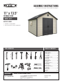 1
1
-
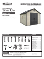 2
2
-
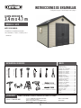 3
3
-
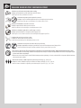 4
4
-
 5
5
-
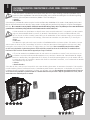 6
6
-
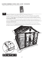 7
7
-
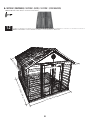 8
8
-
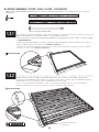 9
9
-
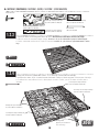 10
10
-
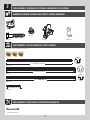 11
11
-
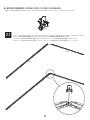 12
12
-
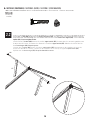 13
13
-
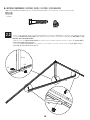 14
14
-
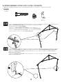 15
15
-
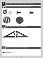 16
16
-
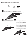 17
17
-
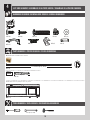 18
18
-
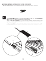 19
19
-
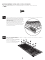 20
20
-
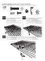 21
21
-
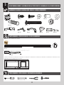 22
22
-
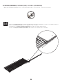 23
23
-
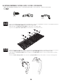 24
24
-
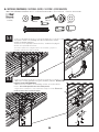 25
25
-
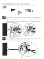 26
26
-
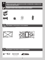 27
27
-
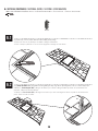 28
28
-
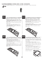 29
29
-
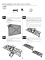 30
30
-
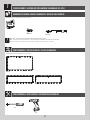 31
31
-
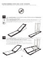 32
32
-
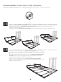 33
33
-
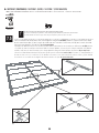 34
34
-
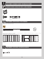 35
35
-
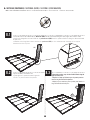 36
36
-
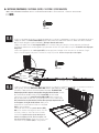 37
37
-
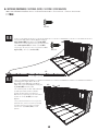 38
38
-
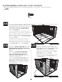 39
39
-
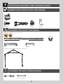 40
40
-
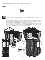 41
41
-
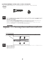 42
42
-
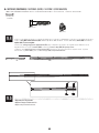 43
43
-
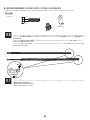 44
44
-
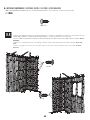 45
45
-
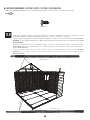 46
46
-
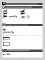 47
47
-
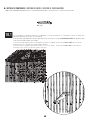 48
48
-
 49
49
-
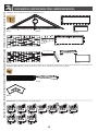 50
50
-
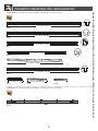 51
51
-
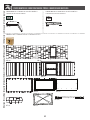 52
52
-
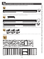 53
53
-
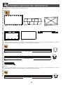 54
54
-
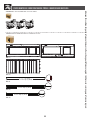 55
55
-
 56
56
-
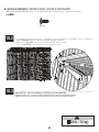 57
57
-
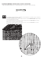 58
58
-
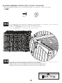 59
59
-
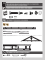 60
60
-
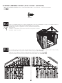 61
61
-
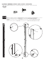 62
62
-
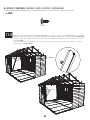 63
63
-
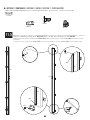 64
64
-
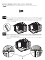 65
65
-
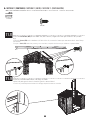 66
66
-
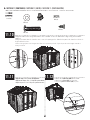 67
67
-
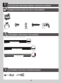 68
68
-
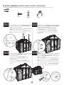 69
69
-
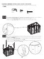 70
70
-
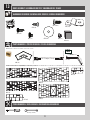 71
71
-
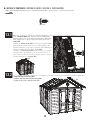 72
72
-
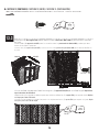 73
73
-
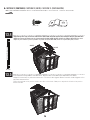 74
74
-
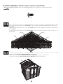 75
75
-
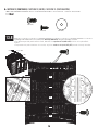 76
76
-
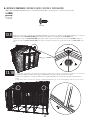 77
77
-
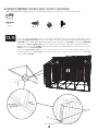 78
78
-
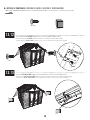 79
79
-
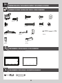 80
80
-
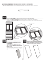 81
81
-
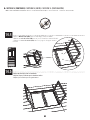 82
82
-
 83
83
-
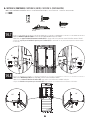 84
84
-
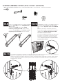 85
85
-
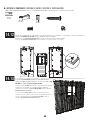 86
86
-
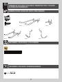 87
87
-
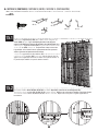 88
88
-
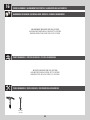 89
89
-
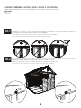 90
90
-
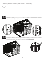 91
91
-
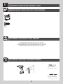 92
92
-
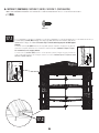 93
93
-
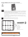 94
94
-
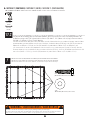 95
95
-
 96
96
-
 97
97
-
 98
98
-
 99
99
-
 100
100
-
 101
101
-
 102
102
-
 103
103
-
 104
104


en otros idiomas
- français: Lifetime 6415 Le manuel du propriétaire
- English: Lifetime 6415 Owner's manual
Artículos relacionados
-
Lifetime 6433 El manual del propietario
-
-
-
-
-
-
-
Lifetime 60138 El manual del propietario
-
-