Yamaha DME24N Manual de usuario
- Categoría
- Equipo de música suplementario
- Tipo
- Manual de usuario
Este manual también es adecuado para


The above warning is located on the top of the unit.
Explanation of Graphical Symbols
The lightning flash with arrowhead symbol
within an equilateral triangle is intended to alert
the user to the presence of uninsulated
“dangerous voltage” within the product’s
enclosure that may be of sufficient magnitude to
constitute a risk of electric shock to persons.
The exclamation point within an equilateral
triangle is intended to alert the user to the
presence of important operating and maintenance
(servicing) instructions in the literature
accompanying the product.
IMPORTANT SAFETY INSTRUCTIONS
1 Read these instructions.
2Keep these instructions.
3 Heed all warnings.
4 Follow all instructions.
5 Do not use this apparatus near water.
6 Clean only with dry cloth.
7 Do not block any ventilation openings. Install in
accordance with the manufacturer’s instructions.
8 Do not install near any heat sources such as
radiators, heat registers, stoves, or other
apparatus (including amplifiers) that produce heat.
9 Do not defeat the safety purpose of the polarized
or grounding-type plug. A polarized plug has two
blades with one wider than the other. A grounding
type plug has two blades and a third grounding
prong. The wide blade or the third prong are
provided for your safety. If the provided plug does
not fit into your outlet, consult an electrician for
replacement of the obsolete outlet.
10 Protect the power cord from being walked on or
pinched particularly at plugs, convenience
receptacles, and the point where they exit from the
apparatus.
11 Only use attachments/accessories specified by
the manufacturer.
12 Use only with the cart, stand,
tripod, bracket, or table
specified by the manufacturer,
or sold with the apparatus.
When a cart is used, use
caution when moving the cart/
apparatus combination to avoid
injury from tip-over.
13 Unplug this apparatus during lightning storms or
when unused for long periods of time.
14 Refer all servicing to qualified service personnel.
Servicing is required when the apparatus has
been damaged in any way, such as power-supply
cord or plug is damaged, liquid has been spilled or
objects have fallen into the apparatus, the
apparatus has been exposed to rain or moisture,
does not operate normally, or has been dropped.
CAUTION: TO REDUCE THE RISK OF
ELECTRIC SHOCK, DO NOT REMOVE
COVER (OR BACK). NO USER-SERVICEABLE
PARTS INSIDE. REFER SERVICING TO
QUALIFIED SERVICE PERSONNEL.
CAUTION
RISK OF ELECTRIC SHOCK
DO NOT OPEN
WARNING
TO REDUCE THE RISK OF FIRE OR ELECTRIC SHOCK,
DO NOT EXPOSE THIS APPARATUS TO RAIN OR MOISTURE.

1. IMPORTANT NOTICE: DO NOT MODIFY THIS UNIT!
This product, when installed as indicated in the instructions con-
tained in this manual, meets FCC requirements. Modifications not
expressly approved by Yamaha may void your authority, granted by
the FCC, to use the product.
2. IMPORTANT: When connecting this product to accessories and/
or another product use only high quality shielded cables. Cable/s
supplied with this product MUST be used. Follow all installation
instructions. Failure to follow instructions could void your FCC
authorization to use this product in the USA.
3. NOTE: This product has been tested and found to comply with the
requirements listed in FCC Regulations, Part 15 for Class “B” digital
devices. Compliance with these requirements provides a reason-
able level of assurance that your use of this product in a residential
environment will not result in harmful interference with other elec-
tronic devices. This equipment generates/uses radio frequencies
and, if not installed and used according to the instructions found in
the users manual, may cause interference harmful to the operation
of other electronic devices. Compliance with FCC regulations does
* This applies only to products distributed by YAMAHA CORPORATION OF AMERICA. (class B)
not guarantee that interference will not occur in all installations. If
this product is found to be the source of interference, which can be
determined by turning the unit “OFF” and “ON”, please try to elimi-
nate the problem by using one of the following measures:
Relocate either this product or the device that is being affected by
the interference.
Utilize power outlets that are on different branch (circuit breaker or
fuse) circuits or install AC line filter/s.
In the case of radio or TV interference, relocate/reorient the
antenna. If the antenna lead-in is 300 ohm ribbon lead, change the
lead-in to co-axial type cable.
If these corrective measures do not produce satisfactory results,
please contact the local retailer authorized to distribute this type of
product. If you can not locate the appropriate retailer, please con-
tact Yamaha Corporation of America, Electronic Service Division,
6600 Orangethorpe Ave, Buena Park, CA90620
The above statements apply ONLY to those products distributed by
Yamaha Corporation of America or its subsidiaries.
FCC INFORMATION (U.S.A.)
IMPORTANT NOTICE FOR THE UNITED KINGDOM
Connecting the Plug and Cord
WARNING: THIS APPARATUS MUST BE EARTHED
IMPORTANT. The wires in this mains lead are coloured in accordance
with the following code:
GREEN-AND-YELLOW : EARTH
BLUE : NEUTRAL
BROWN : LIVE
As the colours of the wires in the mains lead of this apparatus may not
correspond with the coloured markings identifying the terminals in
your plug proceed as follows:
The wire which is coloured GREEN-and-YELLOW must be connected
to the terminal in the plug which is marked by the letter E or by the
safety earth symbol or colored GREEN or GREEN-and-YELLOW.
The wire which is coloured BLUE must be connected to the terminal
which is marked with the letter N or coloured BLACK.
The wire which is coloured BROWN must be connected to the termi-
nal which is marked with the letter L or coloured RED.
• This applies only to products distributed by Yamaha-Kemble Music (U.K.) Ltd. (3 wires)
ADVARSEL!
Lithiumbatteri—Eksplosionsfare ved fejlagtig håndtering. Udskiftning
må kun ske med batteri af samme fabrikat og type. Levér det brugte
batteri tilbage til leverandoren.
VARNING
Explosionsfara vid felaktigt batteribyte. Använd samma batterityp eller
en ekvivalent typ som rekommenderas av apparattillverkaren.
Kassera använt batteri enligt fabrikantens instruktion.
VAROITUS
Paristo voi räjähtää, jos se on virheellisesti asennettu. Vaihda paristo
ainoastaan laitevalmistajan suosittelemaan tyyppiin. Hävitä käytetty
paristo valmistajan ohjeiden mukaisesti.
(lithium caution)
This product contains a battery that contains perchlorate material.
Perchlorate Material—special handling may apply,
See www.dtsc.ca.gov/hazardouswaste/perchlorate.
• This applies only to products distributed by YAMAHA CORPORATION OF AMERICA. (Perchlorate)
NEDERLAND / THE NETHERLANDS
• Dit apparaat bevat een lithium batterij voor geheugen back-up.
• This apparatus contains a lithium battery for memory back-up.
• Raadpleeg uw leverancier over de verwijdering van de batterij op het
moment dat u het apparaat ann het einde van de levensduur of
gelieve dan contact op te nemen met de vertegenwoordiging van
Yamaha in uw land.
•For the removal of the battery at the moment of the disposal at the
end of life please consult your retailer or Yamaha representative
office in your country.
• Gooi de batterij niet weg, maar lever hem in als KCA.
• Do not throw away the battery. Instead, hand it in as small chemical
waste.
(lithium disposal)

DME64N/DME24N Owner’s Manual
4
PRECAUTIONS
PLEASE READ CAREFULLY BEFORE PROCEEDING
* Please keep this manual in a safe place for future reference.
WARNING
Always follow the basic precautions listed below to avoid the possibility of serious injury or even death from
electrical shock, short-circuiting, damages, fire or other hazards. These precautions include, but are not limited
to, the following:
• Only use the voltage specified as correct for the device. The required
voltage is printed on the name plate of the device.
• Use only the specified power cord.
• Do not place the power cord near heat sources such as heaters or
radiators, and do not excessively bend or otherwise damage the cord,
place heavy objects on it, or place it in a position where anyone could walk
on, trip over, or roll anything over it.
• Be sure to connect to an appropriate outlet with a protective grounding
connection. Improper grounding can result in electrical shock.
• Do not open the device or attempt to disassemble the internal parts or
modify them in any way. The device contains no user-serviceable parts. If
it should appear to be malfunctioning, discontinue use immediately and
have it inspected by qualified Yamaha service personnel.
• Do not expose the device to rain, use it near water or in damp or wet
conditions, or place containers on it containing liquids which might spill
into any openings.
• Never insert or remove an electric plug with wet hands.
• If the power cord or plug becomes frayed or damaged, or if there is a
sudden loss of sound during use of the device, or if any unusual smells or
smoke should appear to be caused by it, immediately turn off the power
switch, disconnect the electric plug from the outlet, and have the device
inspected by qualified Yamaha service personnel.
• If this device should be dropped or damaged, immediately turn off the
power switch, disconnect the electric plug from the outlet, and have the
device inspected by qualified Yamaha service personnel.
CAUTION
Always follow the basic precautions listed below to avoid the possibility of physical injury to you or others, or
damage to the device or other property. These precautions include, but are not limited to, the following:
• Remove the electric plug from the outlet when the device is not to be used
for extended periods of time, or during electrical storms.
• When removing the electric plug from the device or an outlet, always hold
the plug itself and not the cord. Pulling by the cord can damage it.
• Before moving the device, remove all connected cables.
• When setting up the device, make sure that the AC outlet you are using is
easily accessible. If some trouble or malfunction occurs, immediately turn
off the power switch and disconnect the plug from the outlet. Even when
the power switch is turned off, electricity is still flowing to the product at
the minimum level. When you are not using the product for a long time,
make sure to unplug the power cord from the wall AC outlet.
•Avoid setting all equalizer controls and faders to their maximum.
Depending on the condition of the connected devices, doing so may cause
feedback and may damage the speakers.
• Do not expose the device to excessive dust or vibrations, or extreme cold
or heat (such as in direct sunlight, near a heater, or in a car during the day)
to prevent the possibility of panel disfiguration or damage to the internal
components.
• Do not place the device in an unstable position where it might accidentally
fall over.
Power supply/Power cord
Do not open
Water warning
If you notice any abnormality
Power supply/Power cord Location
(5)-1 1/2

DME64N/DME24N Owner’s Manual
5
• Do not block the vents. This device has ventilation holes at the front and
rear to prevent the internal temperature from rising too high. In particular,
do not place the device on its side or upside down, or place it in any
poorly-ventilated location, such as a bookcase or closet.
• Do not use the device in the vicinity of a TV, radio, stereo equipment,
mobile phone, or other electric devices. Otherwise, the device, TV, or radio
may generate noise.
• Before connecting the device to other devices, turn off the power for all
devices. Before turning the power on or off for all devices, set all volume
levels to minimum.
• Be sure to connect to a properly grounded power source. A ground screw
terminal is provided on the rear panel for safely grounding the device and
preventing electrical shock.
• Remove the power plug from the AC outlet when cleaning the device.
• Do not insert your fingers or hand in any gaps or openings on the device
(vents, ports, etc.).
• Condensation can occur in the device due to rapid, drastic changes in
ambient temperature—when the device is moved from one location to
another, or air conditioning is turned on or off, for example. Using the
device while condensation is present can cause damage. If there is reason
to believe that condensation might have occurred, leave the device for
several hours without turning on the power until the condensation has
completely dried out.
•Avoid inserting or dropping foreign objects (paper, plastic, metal, etc.)
into any gaps or openings on the device (vents, ports, etc.) If this
happens, turn off the power immediately and unplug the power cord from
the AC outlet. Then have the device inspected by qualified Yamaha service
personnel.
• Do not use the device or headphones for a long period of time at a high or
uncomfortable volume level, since this can cause permanent hearing loss.
If you experience any hearing loss or ringing in the ears, consult a
physician.
• Do not rest your weight on the device or place heavy objects on it, and
avoid use excessive force on the buttons, switches or connectors.
This device has a built-in backup battery that maintains data in internal
memory even when the device’s power is switched off. The backup battery
will eventually become depleted, however, and when that happens the
contents of the internal memory will be lost.* To prevent loss of data be sure
to replace the backup battery before it becomes fully depleted. When the
remaining capacity of the backup battery becomes so low that it needs to be
replaced a “Low Battery” or “No Battery” message will appear on the display
during operation or when the device is powered on. If either of these
messages appears do not turn off the power and immediately transfer any
data you want to save to a computer or other external storage device, then
have qualified Yamaha service personnel replace the backup battery. The
average life of the internal backup battery is approximately 5 years,
depending on operating conditions.
* Data items maintained in the internal memory by the backup battery are as
follows:
• Current scene parameters and number.
• Device parameters (SLOT, HA, UTILITY, Master Mute/Level, etc.).
• Event log.
Data items other than those described above are stored in memory that does
not require backup power, and will be retained even if the backup battery
fails.
Do not turn the [POWER] switch on and off repeatedly and rapidly. Be sure to wait six seconds or more between turning the power to the unit off and then on.
Always turn the power off when the device is not in use.
The performance of components with moving contacts, such as switches, volume controls, and connectors, deteriorates over time. Consult qualified Yamaha service
personnel about replacing defective components.
Connections
Maintenance
Handling caution
Backup battery
Yamaha cannot be held responsible for damage caused by improper use or modifications to the device, or data that is lost or destroyed.
• The illustrations in this document are for instructional purposes, and may appear somewhat different from the actual equipment.
• The bitmap fonts used in this device have been provided by and are the property of Ricoh Co., Ltd.
• CobraNet and Peak Audio are trademarks of Cirrus Logic, Inc.
• Ethernet is a trademark of Xerox Corporation.
• All other trademarks are the property of their respective holders and are hereby acknowledged.
(5)-1 2/2

Foreword
DME64N/DME24N Owner’s Manual
6
Foreword
Thank you for choosing a Yamaha DME64N/24N Digital Mixing Engine.
Using the supplied DME Designer software, the DME64N and DME24N can be easily configured to handle
a wide range of audio processing applications – institutional audio installations, sub-mixing, speaker system
control, matrix and routing, multi-effect processing, and much more.
In order to take full advantage of the features and performance provided by the DME64N/24N, we urge you
to read this owner’s manual thoroughly before use, and keep it in a safe place for future reference.
The Yamaha Pro Audio web site is at: http://www.yamahaproaudio.com/

DME64N/DME24N Owner’s Manual
7
Foreword 8
Accessories (Please make sure the following items
are included in the package.) . . . . . . . . . . . . . . . 8
Options . . . . . . . . . . . . . . . . . . . . . . . . . . . . . . . 8
About the Product Names . . . . . . . . . . . . . . . . . 8
About the Firmware Version . . . . . . . . . . . . . . . 8
Preparation . . . . . . . . . . . . . . . . . . . . . . . . . . . . 8
Connecting the AC power cord . . . . . . . . . . . . . . . . . . . .8
Turning the power on and off. . . . . . . . . . . . . . . . . . . . . .8
Introduction to the DME64N/24N 9
Differences between DME64N/24N . . . . . . . . . 9
DME64N/24N Features . . . . . . . . . . . . . . . . . . 9
Audio System Network . . . . . . . . . . . . . . . . . . . 9
Glossary for the DME64N/24N . . . . . . . . . . . . 9
Signal Types . . . . . . . . . . . . . . . . . . . . . . . . . . 11
System Examples . . . . . . . . . . . . . . . . . . . . . . . 12
About DME Designer . . . . . . . . . . . . . . . . . . . 13
The Controls and Connectors 14
Front Panel . . . . . . . . . . . . . . . . . . . . . . . . . . . 14
Rear Panel . . . . . . . . . . . . . . . . . . . . . . . . . . . . 16
Setup 18
Setup Procedure. . . . . . . . . . . . . . . . . . . . . . . . 18
I/O Card Installation. . . . . . . . . . . . . . . . . . . . 20
Compatible I/O Cards . . . . . . . . . . . . . . . . . . . . . . . . . .20
I/O Card Installation Procedure . . . . . . . . . . . . . . . . . . .21
Connecting to a Computer 22
USB Connection . . . . . . . . . . . . . . . . . . . . . . . 22
Ethernet Connection ([NETWORK] Connector) . . .23
Audio I/O Connection 26
Analog Audio Connection ([IN] and [OUT] Connectors)
(DME24N only). . . . . . . . . . . . . . . . . . . . . . . . . . . . . . .26
I/O Slots. . . . . . . . . . . . . . . . . . . . . . . . . . . . . . . . . . . . .27
Connecting to an External Device 28
Remote Connection ([REMOTE] Connector). 28
Controlling external head amplifiers from the DME64N/24N .28
Controlling a DME24N’s internal head amps from a digital mixer . 29
Controlling the DME64N/24N from an external device .29
MIDI Connection ([MIDI] Connectors) . . . . . 30
Cascade Connection ([Cascade] Connectors)
(DME64N only) . . . . . . . . . . . . . . . . . . . . . . . 31
WORD CLOCK Connection ([WORD CLOCK]
Connectors) . . . . . . . . . . . . . . . . . . . . . . . . . . . 32
GPI Connection ([GPI] Connectors). . . . . . . . 33
Panel Operation and Displays 34
Basic Operation . . . . . . . . . . . . . . . . . . . . . . . . 34
Main Display . . . . . . . . . . . . . . . . . . . . . . . . . . 35
Parameter Edit Displays. . . . . . . . . . . . . . . . . . 36
Editing User Defined Button . . . . . . . . . . . . . . . . . . . . .38
Mute Switching . . . . . . . . . . . . . . . . . . . . . . . . . . . . . . .39
Output Level Control . . . . . . . . . . . . . . . . . . . . . . . . . . .39
Scene Recall . . . . . . . . . . . . . . . . . . . . . . . . . . . . . . . . . .39
Scene Store . . . . . . . . . . . . . . . . . . . . . . . . . . . . . . . . . . .40
Monitoring . . . . . . . . . . . . . . . . . . . . . . . . . . . . . . . . . . .40
Spectrum Display. . . . . . . . . . . . . . . . . . . . . . . 41
Level Meter Display. . . . . . . . . . . . . . . . . . . . . 42
Initializing the DME64N/DME24N . . . . . . . . 43
Utility Displays . . . . . . . . . . . . . . . . . . . . . . . . 44
Items accessible via the Utility display. . . . . . . . . . . . . . .44
Utility Display Operation . . . . . . . . . . . . . . . . . . . . . . . .46
Info Page. . . . . . . . . . . . . . . . . . . . . . . . . . . . . . . . . . . . .46
Network Settings (Net) Page. . . . . . . . . . . . . . . . . . . . . .47
Display Setup (Disp) Page . . . . . . . . . . . . . . . . . . . . . . .47
Security Setup (Lock) Page . . . . . . . . . . . . . . . . . . . . . . .48
Miscellaneous Setup (Misc) Page . . . . . . . . . . . . . . . . . .49
Word Clock Setup (WCLK) Page. . . . . . . . . . . . . . . . . .50
Slot Information (Slot) Page . . . . . . . . . . . . . . . . . . . . . .51
MIDI Setup (MIDI) Page. . . . . . . . . . . . . . . . . . . . . . . .51
GPI Setup (GPI) Page. . . . . . . . . . . . . . . . . . . . . . . . . . .53
Head Amplifier Setup (HA) Page . . . . . . . . . . . . . . . . . .54
Cascade Setup (CASCAD) Page . . . . . . . . . . . . . . . . . . .55
Check Page . . . . . . . . . . . . . . . . . . . . . . . . . . . . . . . . . . .56
References 57
Options . . . . . . . . . . . . . . . . . . . . . . . . . . . . . . 57
ICP1. . . . . . . . . . . . . . . . . . . . . . . . . . . . . . . . . . . . . . . .57
CP4SW, CP4SF, and CP1SF . . . . . . . . . . . . . . . . . . . . .57
Error Messages. . . . . . . . . . . . . . . . . . . . . . . . . 58
Troubleshooting . . . . . . . . . . . . . . . . . . . . . . . 61
Specifications . . . . . . . . . . . . . . . . . . . . . . . . . . 62
Input/Output Characteristics. . . . . . . . . . . . . . 63
Control I/O . . . . . . . . . . . . . . . . . . . . . . . . . . . 63
Connector Pin Assign . . . . . . . . . . . . . . . . . . . 65
Dimensions . . . . . . . . . . . . . . . . . . . . . . . . . . . 67
MIDI Data Format . . . . . . . . . . . . . . . . . . . . . 68
Glossary . . . . . . . . . . . . . . . . . . . . . . . . . . . . . . 73
Index 75
Contents
Foreword
Introduction to
the DME64N/24N
The Controls
and Connectors
Preparation
Audio I/O
Connection
Connecting to
a Computer
Connecting to an
External Device
Panel Operation
and Displays
References

Foreword
Accessories (Please make sure the following items are included in the package.)
DME64N/DME24N Owner’s Manual
8
Thank you for choosing a Yamaha DME64N/24N Digital Mixing Engine.
In order to take full advantage of the features and performance provided by the DME64N/24N, we urge you to read this
owner’s manual thoroughly before connecting or using the unit. Keep this manual in a safe place for future reference.
Accessories (Please make
sure the following items are
included in the package.)
• DME64N/DM24N Owner’s Manual
(This document)
•AC power cord
•AC plug clamp
•Euroblock plug (16P) x 2
•Euroblock plug (8P) x 4 (DME64N only)
•Euroblock plug (3P) x 16 (DME24N only)
Options
Control Panels
• ICP1 Intelligent Control Panel
• CP4SW Control Panel
• CP4SF Control Panel
• CP1SF Control Panel
About the Product Names
In this manual, models DME64N, DME24N, DME8i-C,
DME8o-C, DME4io-C, DME8i-ES, DME8o-ES and
DME4io-ES are categorized as DME series, and models
DME8i-C, DME8o-C, DME4io-C, DME8i-ES,
DME8o-ES and DME4io-ES are all called the “DME
Satellite”.
About the Firmware Version
You can download the latest firmware from the following
Yamaha website.
http://www.yamahaproaudio.com/downloads/
Preparation
Connecting the AC power cord
First plug the female-connector end of the AC cord into
the [AC IN] socket on the rear panel of the DME64N/
24N, then plug the male plug into an appropriate AC
mains outlet.
Be sure to use the voltage specified for the device.
Turning the power on and off
1. Press the [POWER] switch to turn on the
power to the DME64N/24N.
2. Press the [POWER] switch again to turn off
the power.
Foreword
NOTE
For more information on your Control Panel, refer to the
owner’s manual that came with the Control Panel, as well as the
DME Designer Owner’s Manual.
Be sure to turn all devices OFF before connecting AC
mains power.
To prevent the initial power-on surge from generating a
large noise spike or damaging your speaker system, turn
the devices on in the following order: audio sources,
mixer (such as M7CL or PM5D), DME64N/24N, and
finally power amplifiers.
Reverse this order when turning power off.
NOTE
The DME64N/24N remembers scene settings when you turn
off the power.
When you turn on the power to the DME64N/24N, it will
start up with the same scene settings.
You can set up the DME64N/24N so that at the startup it will
recall the scene selected before you turned off the power to the
device. (page 49)
Do NOT turn off the power to the DME64N/24N
while it is receiving data from DME Designer or while it
is being manipulated from an external device. Otherwise,
a malfunction may occur.
Even when the power switch is turned off, electricity is
still flowing to the product all the minimum level.When
you are not using the product for a long time, make sure
to unplug the power cord from the wall AC outlet.
CAUTION
CAUTION
CAUTION
CAUTION

Introduction to the DME64N/24N
Differences between DME64N/24N
DME64N/DME24N Owner’s Manual
9
Differences between DME64N/24N
The DME64N has four I/O card slots, while the DME24N has one I/O card slot and eight channels of built-
in analog audio I/O.
A single I/O card can handle up to 16 channels of audio I/O, so the DME64N can handle a maximum of 64
audio I/O channels. The DME24N can handle up to 24 audio I/O channels.
The DME64N has approximately double the DSP processing power of the DME24N.
DME64N/24N Features
In addition to basic mixing and matrix output functions, the DME64N/24N includes a equalizers, compressors,
delay, etc. – that can be patched together via DME Designer to configure just about any audio system you need.
Audio System Network
Multiple DME series units that are interconnected in a network via Ethernet function as a single audio system.
In a DME audio system, a group of the same models that can be operated in sync is called a “device group;”
audio processing divisions that accommodate multiple device groups are called “zones;” and the entire area ser-
viced by the acoustic system is called an “area.”
Each device group always includes one DME series unit that functions as the “group master” and controls all
other DME series units in the same device group.
If a computer is connected to the network, you can use the computer to control an entire device group via the
group master.
Glossary for the DME64N/24N
This section explains terminology specific to the DME64N/24N.
Components and parameters
The individual audio processing modules (equalizers, compressors, etc.) are called “components.”
External head amplifier control modules are also available as components.
Changing the parameters of components enables control over the operation of the components.
Configuration
A “configuration” is a complete set of components for constructing an audio system.
Each configuration determines the audio function(s) of the corresponding DME64N/24N unit.
All parameter sets included with each component in a configuration are called “preset parameters.”
One DME64N/24N unit has a number of configurations, and a configuration has a number of preset parame-
ters.
User Defined buttons
Assigning parameters to be User Defined Buttons enables you to control the device from the ICP1 and the
DME64N/DME24N.
Refer to the DME Designer Owner’s Manual for details.
Introduction to the DME64N/24N

Introduction to the DME64N/24N
Glossary for the DME64N/24N
DME64N/DME24N Owner’s Manual
10
Scene
A combination of all configuration and preset parameters is called a “scene.”
Scenes can be recalled from an ICP1, GPI device, other external controllers, DME64N/DME24N, or comput-
er.
Up to 999 scenes can be stored for each device group.
Scene structure
Scene change
16 x 8
Scene
Scene 1
Scene 2
Scene 999
Component
Configuration
Preset
Parameter
Ex.: Gate
• Attack
• Decay
• Range
• Threshold
• Key in
• Hold
Matrix Mixer
96kHz
88.2kHz
48kHz
44.1kHz
EXT.
CLOCK
MID
MASTER
NETWORK
PEAK
SIGNAL
PEAK
SIGNAL
IN
OUT
SCENE NUMBER
12345 678
12345 678
96kHz
88.2kHz
48kHz
44.1kHz
EXT.
CLOCK
MID
MASTER
NETWORK
PEAK
SIGNAL
PEAK
SIGNAL
IN
OUT
SCENE NUMBER
12345 678
12345 678
First Act Dark Change Second Act
Band Set
Play Set
Stage Stage Stage
Play
Set
Band
Set
Band Set
Play Set
Scene 1 Scene Recall Scene 2

Introduction to the DME64N/24N
Signal Types
DME64N/DME24N Owner’s Manual
11
Signal Types
DME64N/24N audio system signals can be broadly categorized as follows.
1 Audio
The DME64N/24N will be required to send and receive audio signals to and from other DME series units as
well as other audio equipment.
Audio signal transmission and reception will occur primarily via the [INPUT] and [OUTPUT] connectors on
the DME24N.
2 Control signals within a device group
Device group control signals control all DME series devices in the group.
There are two types of device group control signals, as follows:
• Control signals between the computer and the group master DME series unit
• Control signals between the group master DME series unit and the other DME series
units
You can use the DME Designer application to control the entire device group, such as sending components to
the devices and setting the parameters as required.
3 Control signals between devices outside the device group
These signals provide communication and control between individual devices.
Included in this category are MIDI messages transferred between [USB] connectors, GPI signals transferred be-
tween [GPI] connectors, and remote head amp control signals handled via the [REMOTE] connector.
Type of signals handled by the DME64N/24N
Connector Audio Signal Device Control Word Clock
Reference
Page
[USB]
Connector
–•Control signals between computer and
DNE64N/24N
• MIDI messages
–22
[NETWORK]
Connector
–•Control signals between computer and
DNE64N/24N
• Control signals between DME series
unit.
–23
[MIDI]
Connector
– Control signals (MIDI commands)
between MIDI controller and DME64N/
24N.
–30
[GPI]
Connector
– Control signals between GPI device (GPI
controller, etc.) and DME series unit
–33
[CASCADE]
Connector
(DME64N
only)
32 channels of
input/output.
Control signals from the digital mixer to
the DME64N
Word clock transmission and
reception to and from other
devices.
31
[WORD
CLOCK]
Connector
––Word clock transmission and
reception to and from other
devices.
32
[REMOTE]
Connector
–•Control signals to/from an external
device (such as AD8HR head amplifier)
• Control signals for a digital mixer and
internal head amp
• Control signals with a controller such as
an AMX or Crestron
• MIDI messages
–28
(Audio I/O
Connectors)
(DME24N
only)
8 channels of
input and output.
––26
(I/O Slot) Number of I/O
channels depends
on card.
Serial signal transmission/reception
(depending on function of card).
Word clock transmission and
reception to and from other
devices (depending on function
of card).
27

Introduction to the DME64N/24N
System Examples
DME64N/DME24N Owner’s Manual
12
System Examples
Large systems using CobraNet
HOMEHOME UTILITYUTILITYSCENESCENE LEVELLEVEL MUTEMUTE
ENTERENTERCANCELCANCEL
USB
PEAK
PEAK
SIGNAL
SIGNAL
PEAK
PEAK
SIGNAL
SIGNAL
PEAK
PEAK
SIGNAL
SIGNAL
INPUT
INPUT
DIGITAL MIXING ENGINE SATELLITE
USB
PEAK
PEAK
SIGNAL
SIGNAL
PEAK
PEAK
SIGNAL
SIGNAL
PEAK
PEAK
SIGNAL
SIGNAL
INPUT
INPUT
DIGITAL MIXING ENGINE SATELLITE
USB
PEAK
PEAK
SIGNAL
SIGNAL
PEAK
PEAK
SIGNAL
SIGNAL
PEAK
PEAK
SIGNAL
SIGNAL
INPUT
INPUT
DIGITAL MIXING ENGINE SATELLITE
USB
PEAK
PEAK
SIGNAL
SIGNAL
PEAK
PEAK
SIGNAL
SIGNAL
PEAK
PEAK
SIGNAL
SIGNAL
INPUT
INPUT
DIGITAL MIXING ENGINE SATELLITE
96kHz
88.2kHz
48kHz
44.1kHz
EXT.
CLOCK
MID
MASTER
NETWORK
PEAK
SIGNAL
PEAK
SIGNAL
IN
OUT
SCENE NUMBER
12345 678
12345 678
96kHz
88.2kHz
48kHz
44.1kHz
EXT.
CLOCK
MID
MASTER
NETWORK
PEAK
SIGNAL
PEAK
SIGNAL
IN
OUT
SCENE NUMBER
12345 678
12345 678
DME8o-C
DME8o-C
DME8o-C
DME8o-C
DME8i-C
DME8i-C
DME8i-C
DME8i-C
DME24N
DME64N
DME24N
MY16-CII
MY16-CII
MY16-CII x 4
ICP1
Computer
Hub
Hub
Hub
Hub
Hub
Hub
Hub
Hub
Space BSpace A
Space C
Space D
Analog In
Analog In
Analog In
Analog In
Analog Out
Analog Out
Analog Out
Analog Out
Analog In
Analog In
Analog Out
Ethernet
CobraNet
Ethernet Switching Hub
CobraNet Switching Hub
Analog Out

Introduction to the DME64N/24N
About DME Designer
DME64N/DME24N Owner’s Manual
13
About DME Designer
DME Designer software enables you to integrate, configure, and control the DME series system from a con-
nected computer.
You can build the DME series audio system using graphic blocks in DME Designer that are displayed on the
computer monitor.
The DME series settings, configuration, and parameter data are transferred from the computer to the DME se-
ries unit via the USB or Ethernet connection.
DME series settings, configuration, and parameter data is sent via USB or Ethernet to the connected DME se-
ries unit. After the data is transmitted, you can disconnect the DME series unit from the computer and use it
as an independent processor.
You can also connect it to a computer and control it in realtime from DME Designer.
If multiple DME series units are connected in the network, DME Designer enables you to build a configuration
that includes those units.
Please download the DME Designer application, driver, DME setup manual, and DME Designer Owner’s
Manual at the following URL: http://www.yamahaproaudio.com/
Refer to the “Connecting to a Computer” (page 22) for more information on connecting a computer to the
DME64N/24N. For details on how to install DME Designer and the drivers that are required for connection,
refer to the “DME Setup Manual.”
Refer to the DME Designer Owner’s Manual for setup and operation instructions.

The Controls and Connectors
Front Panel
DME64N/DME24N Owner’s Manual
14
Front Panel
1 [USB] Connector
A computer can be connected here when it is necessary to
program or control the device. When a USB connection is
to be used, the USB-MIDI driver must be installed on the
computer. Refer to the DME Designer Installation Guide
for installation instructions.
2 [EXT. CLOCK] Indicator
When a clock signal from an external device is selected, the
indicator will light green. If the clock signal is not
appropriate the indicator will flash red. The indicator will
go out when the internal word clock is selected.
3 [96kHz] [88.2kHz] [48kHz] [44.1kHz]
Indicator
Normally, the indicator corresponding to the current word
clock frequency will light green. If a problem with the
master clock is detected all of these indicators will flash red.
2 seconds after a problem is detected with an external
master clock the internal clock will temporarily be selected.
When this happens the indicator corresponding to the
frequency of the internal clock will light green, and all
other indicators will continue to flash red.
4 [NETWORK] Indicator
Lights while data communication is occurring via the
[USB], [NETWORK], or [CASCADE] connector.
Received data causes the indicator to light in green, while
transmitted data causes the indicator to light in orange. If a
problem occurs the indicator will light in red.
The Controls and Connectors
HOMEHOME UTILITYUTILITYSCENESCENE LEVELLEVEL MUTEMUTE
ENTERENTERCANCELCANCEL
HOMEHOME UTILITYUTILITYSCENE LEVELLEVEL MUTEMUTE
ENTERENTERCANCELCANCEL
1
1
2
4
5
6
7
8
7
8
9
9
)
)
^
&
^
&
º
¡
™
£
º
¡
™
£
*(
*(
! @#$%
! @#$%
2
4
5
6
3
3
DME64N
DME24N

The Controls and Connectors
Front Panel
DME64N/DME24N Owner’s Manual
15
5 [MIDI] Indicator
Lights while data communication is occurring via the
[MIDI] connector. Received data causes the indicator to
light green, while transmitted data causes the indicator to
light orange. The indicator will light green when reception
and transmission occur simultaneously. If a problem occurs
the indicator will light red.
6 [MASTER] Indicator
Lights green when the device is operating as the device
group master (page 9). The indicator will not light if the
device is operating as a device group slave. Refer to page 46
for device group master setup instructions.
7 [PEAK] Indicator (DME24N only)
Light red when a signal on the corresponding built-in
analog audio input or output ([IN] and [OUT]
connectors) reaches or exceeds -3 dB.
8 [SIGNAL] Indicator (DME24N only)
Light green when a signal with a level greater than -40 dB
is present at the built-in analog audio inputs and outputs
([IN] and [OUT] connectors).
9 [SCENE NUMBER] Indicator
Shows the current scene number.
) Display
Displays scene information and device parameters.
! [SCENE] Button
Calls the scene recall/store display (page 39). The scene
store display will appear if the button is held for longer
than 2 seconds (page 40). The indicator will light green
while the scene recall or store display is showing.
@ [HOME] Button
Directly recalls the home (main) display. If pressed while
the main display is showing the [HOME] button steps
through the user-defined parameter display pages (refer to
page 38 in this manual).
# [UTILITY] Button
Calls the output level display. If this button is held for
longer than 2 seconds while the main display is showing
the utility display will appear. Switches between the Utility
display pages if pressed while the Utility display is showing.
$ [LEVEL] Button
Calls the output level setup display (page 39).
The indicator will light green.
% [MUTE] Button
Calls the mute display (page 39). The indicator will light
orange when mute is on. The indicator will light green
when mute is off and the mute display is showing, and will
be off if the mute display is not showing.
^ Dial
Adjusts the value of selected parameters.
& [E] [ ▲ ] [ ▼ ] [F] Buttons
Move the display cursor in the corresponding directions.
* [CANCEL] Button
Closes the window on the display.
( [ENTER] Button
Confirms and enters a value or setting.
º [PHONES] Jack
A pair of headphones can be plugged in here.
¡ [PHONES LEVEL] Control
Adjusts the headphone volume. Even when the control is
set to the minimum level, the sound at the headphones is
not completely muted.
™ [MONITOR] Button
Calls the monitoring point slot selection display (page 40).
When the [ENTER] button is pressed to select a slot, the
monitoring point selection display will appear.
The spectrum analyzer display will then appear when the
[ENTER] button is pressed to select a monitoring point.
The indicator will light green while the monitoring slot/
point or spectrum analyzer display is showing.
£ [POWER] Switch
Turns mains power to the device on and off.
NOTE
The DME64N has no built-in analog audio inputs or outputs
([IN] and [OUT] connectors).
Even when the power switch is turned off, electricity is
still flowing to the product all the minimum level.
When you are not using the product for a long time,
make sure to unplug the power cord from the wall AC
outlet.
CAUTION

The Controls and Connectors
Rear Panel
DME64N/DME24N Owner’s Manual
16
Rear Panel
1 [AC IN] Connector
This is the device’s three-pronged AC power connector.
Connect to the AC mains using the supplied AC power
cord. See “Setup” on page 18 for details.
Even when the power switch is turned off, electricity is
still flowing to the product all the minimum level. When
you are not using the product for a long time, make sure
to unplug the power cord from the wall AC outlet.
2 Ground Screw
The supplied AC power cable is a 3-wire type, so if the AC
outlet used is properly earthed the DME64N/24N will be
earthed as well. Hum and interference may by further
reduced in some cases by also connecting the earth screw
to an earth point.
3 [GPI] Connector
This Euroblock connector provides access to the unit’s GPI
(General Purpose Interface) interface for transfer of control
signals to and from external equipment. The DME64N
provides 16 channels of GPI input and output, while the
DME24N provides 8 channels. Each input channel has an
IN terminal and a +V terminal. Output channels each have
an OUT terminal and a GND terminal. The open voltage
at the +V terminal is 5V, while the IN terminal detects
voltage changes from 0V ~ 5V. The OUT terminals output
either signal “L” or “H” at a TTL level.
See “GPI Connection ([GPI] Connectors)” on page 33 for
connection details.
3
8
32
21
)6574
1
9
5674
9
DME64N
DME24N
NOTE
Use the supplied AC cord clamp to prevent accidental
disconnection of the AC power.
NOTE
When connecting to two-prong type AC mains outlets use the
supplied plug adaptor.
NOTE
Connect the device to only one ground point.
Connecting the device to more than ground point can result in
ground loops that can cause increased hum and noise.
CAUTION

The Controls and Connectors
Rear Panel
DME64N/DME24N Owner’s Manual
17
4 [MIDI IN] [MIDI OUT] [MIDI THRU]
Connectors
These are standard MIDI connectors that handle reception
and transmission of MIDI data: [MIDI IN] receives MIDI
data, [MIDI OUT] transmits MIDI data, and [MIDI
THRU] re-transmits MIDI data received at the [MIDI
IN] connector. See “MIDI Connection ([MIDI]
Connectors)” on page 30 for connection details.
5 [WORD CLOCK IN] [WORD CLOCK OUT]
Connectors
These BNC connector receive and transmit word clock
from and to external equipment. See “WORD CLOCK
Connection ([WORD CLOCK] Connectors)” on page 32
for connection details. Word clock settings are available via
the device’s Utility display WCLK page (see page 50 of this
document).
6 [NETWORK] Connector
This is a 100Base-TX/10Base-T Ethernet connector for
connection to a computer or other DME series units.
Normally this connector will be connected to a network
hub via an Ethernet “straight” cable. When two
DME64N/24N units are to be directly connected a “cross”
cable should be used. See “Ethernet Connection
([NETWORK] Connector)” on page 23 for connection
details.
7 [REMOTE] Connector
This 9-pin D-SUB connector allows connection to
Yamaha AD824 or AD8HR remote head amplifier or an
RS-232C/RS-422 compatible controller such as those
from AMX or Crestron. You can also connect a Yamaha
PM5D or DM2000 and control the internal head amps of
DME24N. Refer to page 28 for connection details.
8
[IN] [OUT] Connectors (DME24N only)
These are balanced Euroblock connectors for analog audio
input and output. The analog signal from microphones or
line sources such as CD players can be input via the IN
connectors, while the OUT connectors can deliver analog
output to powered speakers or recording equipment. 48V
phantom power can be supplied to the IN connectors
(page 53). Refer to page 26 for [IN] and [OUT]
connection details.
9 I/O Slots
Optional Yamaha or third-party mini-YGDAI cards can be
plugged in here for system expansion. The DME64N has
four I/O slots, while the DME24N has one.
One expansion card can be plugged into each slot. Refer to
“I/O Card Installation” on page 20 for installation details.
) [CASCADE IN] [CASCADE OUT]
Connectors (DME64N only)
This 68-pin D-SUB connector can be connected to the
CASCADE connector of other devices via a dedicated
cascade cable. The CASCADE connector transmits and
receives control, audio, and word clock signals. Refer to
“Cascade Connection ([Cascade] Connectors” on page 31
for connection details.
NOTE
Use a STP (Shielded Twisted Pair) cable for this connection to
prevent electromagnetic interference.
NOTE
The [IN] and [OUT] connectors each have 24 terminal pins.
Each of the eight inputs and outputs uses three pins – hot, cold,
and ground. Use the supplied 3-pin Euroblock plugs to connect
to the appropriate inputs and outputs.

Preparation
Setup Procedure
DME64N/DME24N Owner’s Manual
18
Setup Procedure
Follow the steps outlined below to prepare the DME64N/24N for operation.
1. Install any required I/O cards.
Refer to “I/O Card Installation” on page 20 for details.
2. Connect the AC power cord.
Be sure to turn all devices OFF before connecting AC mains power.
Attach the cable clamp to prevent accidental disconnection.
Attaching the cable clamp.
Be sure to properly ground the device to prevent possible electrical shock.
First plug the female-connector end of the AC cord into the [AC IN] socket on the rear panel of the
DME64N/24N, then plug the male plug into an appropriate AC mains outlet. Make sure the AC power to be
used complies with the conditions marked on the top cover of the device.
Use only the AC power cord supplied with the DME64N/24N. If the supplied cord is lost or damaged and needs to
be replaced, contact your Yamaha dealer. The use of an inappropriate replacement can pose a fire and shock hazard!
The type of AC power cord provided with the DME64N/24N may be different depending on the country in which
it is purchased (a third prong may be provided for grounding purposes). Improper connection of the grounding
conductor can create the risk of electrical shock. Do NOT modify the plug provided with the DME64N/24N. If the
plug will not fit the outlet, have a proper outlet installed by a qualified electrician. Do not use a plug adapter which
defeats the grounding conductor.
Setup
Security Cover Mounting
Security cover mounting screw holes (M3 size) are provided on the front panel of the unit. The spacings are
423mm width and 96mm (DME64N) / 52mm (DME24N) height. See “Dimensions” on page 67 for
details. A security cover made by the customer or contractor can be attached to the front panel via these
mounting holes to prevent accidental operation. Yamaha cannot supply a security cover.
When mounting a cover make sure that the screws used do not go deeper than 15 millimeters into the front
panel. Also, to ensure that the cover does not come in contact with the panel controls, leave a space of about
20 millimeters between the front panel and the cover.
CAUTION
WARNING

Preparation
Setup Procedure
DME64N/DME24N Owner’s Manual
19
3. Install the DME Designer software and necessary drivers on the computer to be used for
device group control.
See the “DME Setup Manual” (PDF file) for details.
4. Connect devices.
•Network connection
Ethernet connection (page 23)
USB connection (page 22)
• Analog connection (page 26)
•External device connection
Remote connection (page 28)
MIDI connection(page 30)
CASCADE connection(page 31)
WORD CLOCK connection(page 32)
GPI connection (page 33)
5. Turn power to the computer, DME64N/24N, and related devices on. Press the DME64N/24N
[POWER] switch to turn it on.
To prevent the initial power-on surge from generating a large noise spike or damaging your speaker system, turn
devices on in the following order: audio sources, mixer and/or recorders, and finally power amplifiers. Reverse this
order when turning power off.
No information will appear on the display the first time the device is turned on. The appropriate scene and
other data must first be transferred to the device from the DME Designer.
Refer to the “DME Setup Manual” (PDF file) for details.
Once the appropriate data has been transferred to the device, the current number and name will appear on the
display:
If any scene data has been stored in the DME64N/24N, the current scene and its name will be displayed.
6. Set up the DME64N/24N operation parameters.
See the “Utility Display” section on page 44 for details.
NOTE
The “NET” page settings must be set up as required before using the unit for the first time.
CAUTION

Preparation
I/O Card Installation
DME64N/DME24N Owner’s Manual
20
7. Launch the DME Designer application, create configuration and transfer.
DME Designer setup, operation, and data transfer instructions can be found in the DME Designer Manual.
This completes preparation of the DME64N/24N system.
I/O Card Installation
The DME64N has four I/O card slots, and the DME24N has one I/O card slot. The number of audio input channels
available on the DME64N/24N can be increased by plugging the appropriate mini-YGDAI I/O card(s) into the available card
slot(s).
Compatible I/O Cards
As of April, 2007, Yamaha mini-YGDAI cards that can be used with the DME64N/24N are as follows:
The input/output numbers above apply to 44.1/48kHz operation.
(*)
In order to use three or four MY16-C cards, firmware V1.10 or later will be required.
If the serial number written on the upper surface of your DME64N is shown below, a hardware upgrade is needed.
KK, KL, KM, KN, KO, KP, KX, KY are the third and fourth digits of the serial number.
A fee is charged for the hardware upgrade.
For details, contact Yamaha customer support using the contact information located at the end of the “DME64N/24N Owner’s
Manual.”
For the latest information on what cards can be used with the DME64N/24N, visit the Yamaha Pro Audio
website at: http://www.yamahaproaudio.com/
Card Name Function Input Output
No. of Available Cards
DME64N DME24N
MY8-AT ADAT 8 8 4 1
MY8-TD TDIF-1 8 8 4 1
MY8-AE AES/EBU 8 8 4 1
MY4-AD ANALOG IN 4 – 4 1
MY8-AD ANALOG IN 8 – 4 1
MY4-DA ANALOG OUT – 4 4 1
MY8-AD24 ANALOG IN 8 – 4 1
MY8-AD96 ANALOG IN 8 – 4 1
MY8-DA96 ANALOG OUT – 8 4 1
MY8-ADDA96 ANALOG IN/OUT 8 8 4 1
MY8-AE96S AES/EBU 8 8 4 1
MY8-AE96 AES/EBU 8 8 4 1
MY8-AEB AES/EBU 8 8 4 1
MY16-AT ADAT 16 16 4 1
MY16-AE AES/EBU 16 16 4 1
MY16-TD TDIF-1 16 16 4 1
MY16-C CobraNet 16 16 4(*) 1
MY16-CII CobraNet 16 16 4 1

Preparation
I/O Card Installation
DME64N/DME24N Owner’s Manual
21
I/O Card Installation Procedure
1. Make sure that the DME64N/24N power is OFF.
If the power is on, turn it off.
2. Loosen the two card slot screws and remove the slot cover, as shown in the diagram.
3. Slide the I/O card into the slots in the guide rails, as shown in the diagram, and push the
card into the slot.
Be sure to push the card all the way back into the slot so that the card contacts make proper contact with the
slot connector.
4. Secure the card with the attached screws.
Be sure to tighten the screws securely. If the screws are left loose proper contact may be lost and malfunction of
damage may result.
NOTE
The slot cover and screws will need to be re-attached if the I/O card is later removed from the slot, so keep them in a safe place.
Guide Rail
CAUTION

Connecting to a Computer
USB Connection
DME64N/DME24N Owner’s Manual
22
USB Connection
USB connections can be used in the following two ways:
(1) Control the DME64N/24N from DME Designer.
(2) Connect to any individual DME64N/24N and control that DME64N/24N unit by transmitting MIDI
commands from a MIDI sequencer or similar software.
Be sure to follow the procedure below when you make a USB connection with a computer. Otherwise, the
computer and/or DME64N/24N may freeze, resulting in damages or loss of data. If the computer or
DME64N/24N freezes, turn the power to the DME64N/24N off and then on, then restart the computer.
• Before you connect the DME64N/24N to the computer via USB, cancel the computer’s energy saving mode
(such as Suspend, Sleep, or Stand-by mode).
• Before turning on the power to the DME64N/24N, first connect its [USB] connector to the computer’s USB port.
• Before turning the power to the unit on or off, and before connecting or disconnecting the USB cable, take the
following actions:
- Quit all open applications.
- Make sure that the DME64N/24N is NOT transferring any data.
• Be sure to wait six seconds or more between turning the power to the unit on and then off (or off and then on),
or between connecting and disconnecting (or vice versa) the USB cable.
Connecting to a Computer
NOTE
•Refer to the “DME Setup Manual” (PDF file) for details on installing USB-MIDI Driver and DME Designer.
•Make sure that the USB-MIDI Driver’s THRU setting is “OFF.”
NOTE
• When using a DME64N/24N together with the DME Satellite, you must assign the DME Satellite as the master. The
computer on which DME Designer is running can be connected to either the group master or a slave DME series unit.
• The correspondence between the MIDI commands to be received/transmitted and the scene parameters can be set up using DME Designer.
• The USB port being used by DME Designer is not available for use by a MIDI sequencer or other application.
USB
PEAK
PEAK
SIGNAL
SIGNAL
PEAK
PEAK
SIGNAL
SIGNAL
PEAK
PEAK
SIGNAL
SIGNAL
INPUT
INPUT
DIGITAL MIXING ENGINE SATELLITE
HOMEHOME UTILITYUTILITYSCENESCENE LEVELLEVEL MUTEMUTE
ENTERENTERCANCELCANCEL
USB
PEAK
PEAK
SIGNAL
SIGNAL
PEAK
PEAK
SIGNAL
SIGNAL
PEAK
PEAK
SIGNAL
SIGNAL
INPUT
INPUT
DIGITAL MIXING ENGINE SATELLITE
Device Group
DME Satellite
Computer
(Running DME Designer.)
Computer
(Running MIDI
Sequencer or
similar application.)
Ethernet Cable
Switching Hub
Ethernet Cable
DME Satellite
Ethernet
Straight Cable
DME64N/24N
USB Cable
USB Cable
CAUTION

Connecting to a Computer
Ethernet Connection ([NETWORK] Connector)
DME64N/DME24N Owner’s Manual
23
Ethernet Connection ([NETWORK] Connector)
To control the DME64N/24N from the computer via Ethernet, use an Ethernet cable to connect the [NET-
WORK] connector on the rear panel of the DME64N/24N to the computer, then install DME-N Network
Driver.
Two DME series units directly connected via Ethernet
You can connect devices in the same device group directly to each other using Ethernet cables, without connect-
ing them to a switching hub. A cross cable is required to connect between DME64N/24N units.
If one of the units is a DME Satellite then either a cross cable or straight cable can be used since the DME Sat-
ellite supports Auto MDI/MDI-X. In this case, set Link Mode on both units to the same setting. Devices in
different subnet (different network address) groups can be connected via a router or layer-3 compliant switching
hub.
NOTE
•Refer to the “DME Setup Manual” (PDF file) for details on installing DME-N Network Driver.
•Appropriate IP addresses must first be assigned to all devices connected to an Ethernet network.
USB
PEAK
PEAK
SIGNAL
SIGNAL
PEAK
PEAK
SIGNAL
SIGNAL
PEAK
PEAK
SIGNAL
SIGNAL
INPUT
INPUT
DIGITAL MIXING ENGINE SATELLITE
HOMEHOME UTILITYUTILITYSCENESCENE LEVELLEVEL MUTEMUTE
ENTERENTERCANCELCANCEL
DME64N/24N
DME Satellite
Ethernet Cable
USB Cable

Connecting to a Computer
Ethernet Connection ([NETWORK] Connector)
DME64N/DME24N Owner’s Manual
24
Control from a computer in the same subnet group
Control from a computer with a different subnet
NOTE
• The IP addresses in the diagram are examples.
•Use a switching hub that is compatible with 100Base-TX/10Base-T network speeds.
The maximum length of a cable between a switching hub and the DME series is 100 meters. Due to the quality of cables
and switching hub performance, however, proper operation at the maximum length cannot be guaranteed in some cases.
Use a STP (Shielded Twisted Pair) cable to prevent electromagnetic interference.
•If you are using multiple DME series units, set Link Mode on each unit to the same setting. Yamaha recommends that you
select 100Base-TX for the Link Mode setting.
HOMEHOME UTILITYUTILITYSCENESCENE LEVELLEVEL MUTEMUTE
ENTERENTERCANCELCANCEL
USB
PEAK
PEAK
SIGNAL
SIGNAL
PEAK
PEAK
SIGNAL
SIGNAL
PEAK
PEAK
SIGNAL
SIGNAL
INPUT
INPUT
DIGITAL MIXING ENGINE SATELLITE
USB
PEAK
PEAK
SIGNAL
SIGNAL
PEAK
PEAK
SIGNAL
SIGNAL
PEAK
PEAK
SIGNAL
SIGNAL
INPUT
INPUT
DIGITAL MIXING ENGINE SATELLITE
Device Group
Group Master
DME Satellite (IP address: 192.168.0.7)
Ethernet Cable
Switching Hub
Ethernet Straight Cable
Computer
(IP address:
192.168.0.100)
Ethernet Cable
Ethernet
Straight Cable
DME Satellite
(IP address: 192.168.0.3)
(Master ID: 7)
DME64N/24N
(IP address: 192.168.0.250)
(Master ID: 7)
HOMEHOME UTILITYUTILITYSCENESCENE LEVELLEVEL MUTEMUTE
ENTERENTERCANCELCANCEL
USB
PEAK
PEAK
SIGNAL
SIGNAL
PEAK
PEAK
SIGNAL
SIGNAL
PEAK
PEAK
SIGNAL
SIGNAL
INPUT
INPUT
DIGITAL MIXING ENGINE SATELLITE
USB
PEAK
PEAK
SIGNAL
SIGNAL
PEAK
PEAK
SIGNAL
SIGNAL
PEAK
PEAK
SIGNAL
SIGNAL
INPUT
INPUT
DIGITAL MIXING ENGINE SATELLITE
Device Group
Group Master
DME Satellite (IP address: 192.168.0.5)
Ethernet Cable
Ethernet Cable
Ethernet
Straight Cable
Ethernet
Straight Cable
Ethernet
Straight Cable
Switching Hub
Router or
Layer-3
Compliant
Switching
Hub
Computer
Port settings
• Destination network address: 192.168.0.0
• Subnet mask: 255.255.255.0
• Gateway: 192.168.0.254
DME Satellite
(IP address: 192.168.0.3)
(Master ID: 5)
DME64N/24N
(IP address: 192.168.0.12)
(Master ID: 5)

Connecting to a Computer
Ethernet Connection ([NETWORK] Connector)
DME64N/DME24N Owner’s Manual
25
Connecting multiple device groups
HOMEHOME UTILITYUTILITYSCENESCENE LEVELLEVEL MUTEMUTE
ENTERENTERCANCELCANCEL
HOMEHOME UTILITYUTILITYSCENESCENE LEVELLEVEL MUTEMUTE
ENTERENTERCANCELCANCEL
USB
PEAK
PEAK
SIGNAL
SIGNAL
PEAK
PEAK
SIGNAL
SIGNAL
PEAK
PEAK
SIGNAL
SIGNAL
INPUT
INPUT
DIGITAL MIXING ENGINE SATELLITE
USB
PEAK
PEAK
SIGNAL
SIGNAL
PEAK
PEAK
SIGNAL
SIGNAL
PEAK
PEAK
SIGNAL
SIGNAL
INPUT
INPUT
DIGITAL MIXING ENGINE SATELLITE
USB
PEAK
PEAK
SIGNAL
SIGNAL
PEAK
PEAK
SIGNAL
SIGNAL
PEAK
PEAK
SIGNAL
SIGNAL
INPUT
INPUT
DIGITAL MIXING ENGINE SATELLITE
USB
PEAK
PEAK
SIGNAL
SIGNAL
PEAK
PEAK
SIGNAL
SIGNAL
PEAK
PEAK
SIGNAL
SIGNAL
INPUT
INPUT
DIGITAL MIXING ENGINE SATELLITE
Device Group 1 Device Group 2
Group Master
DME Satellite
(IP address: 192.168.0.2)
Group Master
DME Satellite
(IP address: 192.168.0.3)
Ethernet Cable Ethernet Cable
Ethernet
Straight Cable
Ethernet Cable
DME64N/24N
(IP address: 192.168.0.100)
(Master ID: 2)
DME Satellite
(IP address: 192.168.0.40)
(Master ID: 2)
DME Satellite
(IP address: 192.168.0.10)
(Master ID: 3)
DME64N/24N
(IP address: 192.168.0.200)
(Master ID: 3)
Switching Hub
Computer
(IP address: 192.168.0.1)
Switching Hub
Ethernet Straight Cable
Ethernet Straight Cable
Ethernet Cable

Audio I/O Connection
DME64N/DME24N Owner’s Manual
26
Analog Audio Connection ([IN] and [OUT] Connectors) (DME24N only)
The DME24N includes [IN] and [OUT] connectors for 8 channels of analog audio input and output. Wire
the supplied Euroblock plugs as shown below. Head amplifier gain and phantom power settings can be made
via the Utility display HA page described on page 54 of this manual, or via the DME Designer application.
Euroblock Connection
Please be sure to use the supplied Euroblock plugs. If you lose them, contact your nearest Yamaha dealer.
1. Loosen terminal screws.
2. Insert cables.
Audio I/O Connection
Cable preparation
• To prepare the cable for attachment to a Euroblock connector, strip the wire
as shown in the illustration, and use stranded wire to make connections.
With a Euroblock connection, the stranded wire may be prone to breakage
because of metal fatigue due to the weight of the cable or due to vibration.
When rack-mounting your equipment, use a lacing bar when possible to
bundle and fasten the cables.
• If cables will be frequently connected and disconnected, as in the case of a
portable installation, we recommend that you use ferrules with insulation
sleeves. Use a ferrule whose conductor portion has an external diameter of
1.6 mm or less, and a length of approximately 7 mm (such as the AI0,5-
6WH made by the Phoenix Contact corporation).
If you use stranded wire, do not tin (plate with solder) the exposed end.
NOTE
A slotted screwdriver with a blade width of about 3 millimeters is recommended.
approx.
7 mm
approx.
7 mm
1.6 mm
or less
CAUTION
Loosen.
Euroblock Plug
Slotted Screwdriver
Ter minal Screw
3 mm

Audio I/O Connection
DME64N/DME24N Owner’s Manual
27
3. Securely tighten terminal screws.
Pull the cables (not too strongly) to confirm that they are securely connected.
4. Plug the Euroblock plug into the panel connector.
I/O Slots
The DME64N has four I/O card slots, and the DME24N has one I/O card slot. The number of audio input
channels available on the DME64N/24N can be increased by plugging the appropriate mini-YGDAI I/O
card(s) into the available card slot(s). Some types of cards also provide control and/or word clock transmission
and reception functionality.
Refer to “Compatible I/O cards” (page 20) for details on the cards that can be used.
For details on how to install cards, refer to “I/O card Installation Procedure” (page 21).

Connecting to an External Device
Remote Connection ([REMOTE] Connector)
DME64N/DME24N Owner’s Manual
28
Remote Connection ([REMOTE] Connector)
The [REMOTE] connector of the DME64N/24N can be connected to remotely-controllable Yamaha AD8HR
or AD824 head amplifiers (pre-amps), digital mixers, or RS-232C compatible controllers (such as those from
AMX or Crestron). The [REMOTE] connector also transmits and receives MIDI messages.
Controlling external head amplifiers from the DME64N/24N
You can remotely control the AD8HR or AD824 head amplifier settings from DME Designer. Up to eight
AD8HR/AD824 head amplifiers can be connected.
When connecting an AD8HR or AD824 be sure to set the “Utility” screen “MISC” page (see manual page 49)
“Remote” parameter to “HA Control (RS422)”. Also, do change to any other setting than “HA Control
(RS422)” while the unit is connected. Doing so can damage the unit.
When connecting to a combination of AD8HR and AD824 head amplifiers, be sure to place the AD8HR units
closest to the DME64N/24N in the chain, otherwise the AD8HR or AD824 unit(s) may not be properly rec-
ognized by the DME64N/24N.
Connecting to an External Device
NOTE
Only control signals are transmitted and received via the REMOTE connection. Audio connections must be made separately.
D-SUB 9-pin Cable (Interlink Crossover)
REMOTE
HA REMOTE 2HA REMOTE 1 HA REMOTE 1 HA REMOTE 2
AD8HR AD8HR
AD824 AD824 AD824
DME64N/24N
COM PC/RS-422 COM RS-422 COM PC/RS-422 COM RS-422 COM PC/RS-422
Set to HA Control
(RS-422)

Connecting to an External Device
Remote Connection ([REMOTE] Connector)
DME64N/24N Owner’s Manual
29
Controlling a DME24N’s internal head amps from a digital mixer
The internal head amp settings of a DME24N can be remotely controlled from a digital mixer such as the Yama-
ha PM5D or DM2000.
Connect the digital mixer to the DME series’ [REMOTE] connector, and use an Ethernet cable to make con-
nections between the [NETWORK] connectors of the DME series.From the digital mixer, DME series units
can be controlled as an AD8HR.
The gain and the phantom power (+48V) can be controlled.
Controlling the DME64N/24N from an external device
You can remotely control the DME64N/24N from a connected RS-232C or RS-422 compatible controller,
such as those from AMX or Crestron.
When connecting a remote controller via RS-232C or RS-422, be sure to set the “Utility” screen “MISC” page
(see manual page 49) “Remote” parameter to match the controller being connected. Also, do change this setting
while the unit is connected. Doing so can damage the unit.
NOTE
•Only one mixer can be connected within each device group.
• The digital mixer can be connected to any DME series unit, whether it is the group master or a slave unit.
• The ID number of the DME series unit being remotely controlled is specified from DME Designer.
For details on making this setting, refer to the “DME Designer Owner’s Manual.”
•If the connection between DME series units is broken, it will no longer be possible to communicate with DME units of an
ID number that follows the disconnected DME.
• The variable range of GAIN differs between the AD8HR and the DME24N. You cannot use the mixer to specify a value
that exceeds the variable range of the DME24N.
NOTE
Refer to “DME Remote Control Protocol Specifications” on the Yamaha web site for more information on communication
protocols used to control the DME64N/24N from an external device (such as those from AMX or Crestron).
http://www.yamahaproaudio.com/
96kHz
88.2kHz
48kHz
44.1kHz
EXT.
CLOCK
MID
MASTER
NETWORK
PEAK
SIGNAL
PEAK
SIGNAL
IN
OUT
SCENE NUMBER
12345 678
12345 678
96kHz
88.2kHz
48kHz
44.1kHz
EXT.
CLOCK
MID
MASTER
NETWORK
PEAK
SIGNAL
PEAK
SIGNAL
IN
OUT
SCENE NUMBER
12345 678
12345 678
DME64N/24N
REMOTE REMOTE
Ethernet Cable
Switching
Hub
Digital Mixer
D-SUB 9-pin Cable
DME64N/24N

Connecting to an External Device
MIDI Connection ([MIDI] Connectors)
DME64N/DME24N Owner’s Manual
30
MIDI Connection ([MIDI] Connectors)
In this case connection is made to the rear-panel [MIDI] connectors. MIDI commands are sent to the
DME64N/24N from a MIDI device.
By connecting the [MIDI OUT] terminal of a digital mixer (such as the DM2000) to the [MIDI OUT] of the
DME64N/24N and making the proper settings on the mixer and the DME64N/24N, you can change scenes
by sending program change messages from the mixer.
If the [MIDI OUT] connector of the DME64N/24N is connected to the [MIDI IN] connector of an
SPX2000 or similar digital effect unit, and if the DME64N/24N and SPX2000 are set up appropriately,
DME64N/24N program change operations will case the corresponding effect to be recalled on the effect unit.
NOTE
Refer to “MIDI Page” on page 51 for MIDI setup details.
NOTE
The DME Designer can be used to set up the system so that scene recall operations and user parameter control can be carried
out from connected MIDI devices. Refer to the DME Designer manual for details.
MIDI OUT MIDI IN
DME64N/24N
MIDI Cable
DM2000 Digital Mixer or Other Controller
MIDI OUT MIDI IN
DME64N/24N
MIDI Cable
SPX2000 or Other Digital Effect Unit

Connecting to an External Device
Cascade Connection ([Cascade] Connectors) (DME64N only)
DME64N/DME24N Owner’s Manual
31
Cascade Connection ([Cascade] Connectors) (DME64N only)
The rear-panel [CASCADE] connector can be connected to the [CASCADE] connector on another
DME64N/24N or other compatible device via a dedicated cascade cable for bidirectional transfer of control,
audio, and word clock signals. The communication direction automatically switches to unidirectional when
connecting to a mixer such as the PM5D, or bidirectional when connecting to another DME64N/24N unit.
Up to eight DME64N units can be cascade connected.
In the unidirectional mode the audio signal flow is from the [CASCADE OUT] connector to the [CASCADE
IN] connector. For bidirectional communication the data flows in both directions within a single cable, and
input on the same channel from other DME64N units is summed (bus sharing). The total number of audio
channels that can be connected to a mixer or DME64N/24N unit is 32.
Word clock is continuously output from both the [CASCADE IN] and [CASCADE OUT] connectors, and is
received by the corresponding [CASCADE IN] or [CASCADE OUT] connector on the connected device.
In all cases the [CASCADE OUT] of one device must be connected to the [CASCADE IN] connector of the
other. Do not connect [CASCADE IN] to [CASCADE IN], or [CASCADE OUT] to [CASCADE OUT].
Cascade Connection Example
NOTE
Maximum length by the optional dedicated Cascade cables
Unidirectional Cascade connection: 200m (44.1/48kHz), 100m (88.2/96kHz)
Bidirectional Cascade connection: 100m (44.1/48kHz), 30m (88.2/96kHz)
NOTE
Never create a full cascade loop using only DME64N units!
NOTE
It is also possible to remotely control DME series units from the PM5D via a CASCADE connection. In such cases assign the
nearest DME64N unit to the PM5D as the device group master. When using a DME64N/24N together with the DME
Satellite, you must assign the DME Satellite as the master.
Another method of remotely controlling a DME series from a PM5D is via CobraNet connections to MY16-C or MY16-CII
cards.
All DME series units to be controlled from the PM5D must be in the same device group, and the host address of the device
group master must be set to “2.” However, if the PM5D is version 2.20 or higher and the DME Satellite is version 3.07 or
higher, you can set the parameter to any number.
For information on the PM5D DME CONTROL function refer to the PM5D/PM5D-RH Owner’s Manual or to the
“Cascade Setup Guide” available at the Yamaha website.
http://www.yamahaproaudio.com/
DME64NDME64N
IN
OUT
PM5D
DME64N DME64N
IN OUT
OUT
IN OUT
IN
Unidirectional Cascade Connection
Bidirectional Cascade Connection
68-pin Half-pitch D-SUB Cable
68-pin Half-pitch D-SUB Cable
68-pin Half-pitch
D-SUB Cable
68-pin Half-pitch
D-SUB Cable

Connecting to an External Device
WORD CLOCK Connection ([WORD CLOCK] Connectors)
DME64N/DME24N Owner’s Manual
32
WORD CLOCK Connection ([WORD CLOCK] Connectors)
Word clock signals are transferred to and from external devices via the [WORD CLOCK IN] and [WORD
CLOCK OUT] connectors. The [WORD CLOCK OUT] connector can be used to supply the DME64N/
24N word clock to external equipment. Word clock is continuously output by the DME64N/24N during
normal operation. The word clock signal from an external device can be received via the [WORD CLOCK IN]
connector.
To distribute the word clock signal from one device to multiple slave devices, either a word clock distribution
box or daisy-chained connection can be used.
Distribution Box Connection
Daisy Chain Connection
NOTE
Word clock can also be received and transmitted via a mini-YGDAI card installed in an I/O slot, or the [CASCADE IN] and
[CASCADE OUT] connectors. It is necessary to specify whether the DME64N/24N will use the internal word clock or an
external word clock for synchronization. Refer to the Utility display WCLK page described on page 50 of this manual for
details.
NOTE
A device transmitting the word clock signal that will be used by other devices for synchronization is the “word clock master,”
while devices received the word clock are “word clock slaves.”
NOTE
This method is not recommended for large systems.
WC OUT
(BNC)
WC IN
(BNC)
DME64N/24N
Word Clock
Master
Word Clock Slave
WC OUT (BNC)
WC IN (BNC) WC IN (BNC) WC IN (BNC) WC IN (BNC)
DME64N/24N DME64N/24N DME64N/24N DME64N/24N
Word Clock
Master
Word Clock
Distribution Box
Word Clock Slave Word Clock Slave
Word Clock Slave Word Clock Slave
WC OUT
(BNC)
WC OUT
(BNC)
WC OUT (BNC)
WC IN
(BNC)
WC IN
(BNC)
WC IN
(BNC)
DME64N/24N DME64N/24N DME64N/24N
Word Clock
Master
Word Clock Slave
Word Clock Slave
Word Clock Slave

Connecting to an External Device
GPI Connection ([GPI] Connectors)
DME64N/DME24N Owner’s Manual
33
GPI Connection ([GPI] Connectors)
GPI (General Purpose Interface) device (GPI controller, etc.) can be connected to the rear-panel [GPI]
connectors. Using GPI a variety of control signals can be transferred between the DME64N/24N and external
controllers or other devices. The optional CP4SW, CP4SF, and CP1SF control panels are also connected via
GPI.
The DME64N provides 16 channels of GPI input and output, and the DME24N provides 8 channels. Each
channel has an IN terminal, a +V terminal, an OUT terminal and a GND terminal. The +V terminals have an
open-terminal voltage of 5 volts. The IN terminals can detect a full range of input voltages from 0V through
5V, while the OUT terminals output either signal “L” or “H” at a TTL level.
The parameters for each GPI input and output are assigned via the DME Designer application.
Euroblock connectors are used for all GPI input and output connections. Euroblock connection methods are
described in “Euroblock Connection” on page 26 in this manual.
NOTE
For more information on the CP4SW, CP4SF, and CP1SF control panels refer to “CP4SW, CP4SF, and CP1SF” in the
Appendix of this manual (page 53).
NOTE
The DME Designer can be used to set up the system so that scene recall operations and user parameter control can be carried
out from connected GPI control devices. Refer to the DME Designer manual for details.
NOTE
GPI connector calibration procedure is described on page 53 of this manual, in the Utility display GPI page.
IN +V
IN +V GND
OUT GND
Example: Controlling the
DME64N/24N from a switch.
GPI Connection
Example: Controlling the
DME64N/24N via a 10k ohm
linear taper potentiometer.
GPI Connection
Continuous
potentiometer
GPI Connection
Example: Lighting external
LED indicators from the
DME64N/24N.
Max. 16mA
Make sure that the current between
the OUT and GND [GPI] connectors
is less than 16mA.
CAUTION

Panel Operation and Displays
Basic Operation
DME64N/DME24N Owner’s Manual
34
Basic Operation
By pressing the panel keys it is possible to select the DME64N/24N Main display, Utility display, and Parameter Edit displays
that allow individual settings to be edited and changed. refer to the pages listed below for more detailed information about
each display.
[HOME] key ➔ Main Display (page 35)
The Main display can be directly recalled from any display other than the Main display by pressing the
[HOME] key. The Main display shows the current scene information
[HOME] key ➔ User Defined Button Page Selection (page 38)
Pressing the [HOME] key while the Main display is shown sequentially selects the four User Defined Button
pages.
[MUTE] key ➔ Mute Display (page 39)
[LEVEL] key ➔ Output Level Display (page 39)
[SCENE] key ➔ Scene Recall Display (page 39)/Scene Store Display (page 40)
These keys can be pressed from the Main or Utility displays to directly call the related parameter edit displays.
[MONITOR] key ➔ Monitor Point Selection Display (page 40)
This function is useful for level monitoring. When the key is pressed the monitor point selection display will
appear, and the spectrum analyzer display will appear when a selection has been made.
[UTILITY] key ➔ Utility Display (page 44)
The Utility display appears when the [UTILITY] key is pressed for longer than two seconds while the Main
display is showing.
The Utility display includes a number of pages that can be selected in sequence by repeatedly pressing the
[UTILITY] key.
Panel Operation and Displays
HOMEHOME
HOMEHOME
Main display
Switches the pages of the User Defined Button

Panel Operation and Displays
Main Display
DME64N/DME24N Owner’s Manual
35
Main Display
The Main display will appear in a few seconds after the
power is turned on. The Main display shows information
about the current scene.
Up to 24 parameters can be accessed from the DME64N/
24N or ICP1 control panel for each scene. Six parameters
are shown on the Main display at a time.
1 Scene Information
The current scene number and name. Scene names can be
entered by using the DME Designer application.
A maximum of 12 one-byte (Roman) characters can be
displayed in a scene name. When “two-byte” characters are
to be used for languages such as Japanese, the total number
of displayable characters is reduced accordingly.
When the power is turned on the last scene selected before
the power was turned off is automatically recalled.
2 Edit Indicator
If a parameter is changed after recalling a scene, a dot will
appear in the scene number indicator, and “EDIT” will
appear in the display.
3 User Defined Button Names
Displays the User Defined Button. The buttons are
specified by using the DME Designer application.
“No Assign” settings in DME Designer are displayed as
dotted lines. When [Parameter Value Edit] is selected the
display will be a solid line. When [Direct Parameter Value],
[Scene Change], [GPI Out], or [Play Wav File] are
selected, the display will be inverted.
A maximum of 24 buttons can be made available for user
control, but only six buttons can be shown in any one
display page. Press the [HOME] key to switch to other
available button pages. A maximum of 8 one-byte
(Roman) characters can be displayed in a button name.
When “two-byte” characters are to be used for languages
such as Japanese, the total number of displayable characters
is reduced accordingly.
Buttons are selected for editing by using the cursor keys –
[E] [ ▲ ] [ ▼ ] [F] – to select the button, and then
pressing [ENTER].
4 Page Scroll Bar
The scroll bar provides an indication of which parameter
page is currently being displayed. 4 pages are available, and
the scroll bar moves one position to the right each time the
[HOME] key is pressed and a new page of parameters is
selected, and then back to the leftmost position after the
rightmost position has been reached.
5 Mute Indicator
Shows the current mute ON/OFF status.
: Mute ON
: Mute OFF
6 Output Level Indicator
Displays the current output level in 10 increments.
The longer the “bar,” the higher the output level.
7 Panel Lock Icon
This icon appears when the panel lock function is turned
ON.
: Panel Lock ON (Panel controls locked)
NOTE
Nothing will appear on the display if no scene data is stored in
the DME64N/24N scene memory (this is the case when the unit
is initially shipped, for example).
3
1
2
6
4
3
5
7
NOTE
User Defined Button settings are common to the device group.
NOTE
Scroll bar operation is independent for each DME64N/
DME24N unit, and is not linked within a device group.

Panel Operation and Displays
Parameter Edit Displays
DME64N/DME24N Owner’s Manual
36
Parameter Edit Displays
Parameter Edit displays will appear when the [SCENE],
[MUTE], [MONITOR] or other key is pressed to allow
scene changes, level adjustment, and other settings to be
edited as required. Parameter Edit displays are also used to
edit utility parameters.
In most cases the desired parameter edit page can be
accessed by selecting the item you want to edit in the
appropriate display by using the cursor [E], [ ▲ ], [ ▼ ],
and [F] keys, and then pressing the [ENTER] key.
There are basically three types of parameters that can be
accessed via a Parameter Edit display:
•Numeric values
• Lists
• ON/OFF switches
Numeric Parameters
Numeric parameters can be edited in a number of ways,
and depending on the parameter a fader, knob, or
minimum and maximum values may appear to the left of
the numeric value.
A Numeric Value with a fader
A Numeric Value with a Knob
1 Name of parameter selected for editing
2 Fader
3 Knob
4 Minimum and maximum values
5 Current value
Panel Lock
The panel controls can be “locked” to prevent
accidental mis-operation.
To activate the panel lock function simultaneously press
and hold the [HOME] and [ENTER] keys for longer
than 2 seconds.
The panel lock icon will appear on the Main display
when the panel is locked.
Panel Lock can be disengaged by pressing the
[CANCEL] key for longer than 2 seconds.
NOTE
The panel lock function can be set up to lock just the panel keys
(“Key Only”), or the panel keys and GPI control (“Key+GPI”).
You can also select whether or not the panel lock function is
automatically engaged when the unit is initially turned on. This
selection can be made via the Utility display “Lock” page (refer to
the page 48).
Panel lock icon
1
2
5
4
1
3
5
4

Panel Operation and Displays
Parameter Edit Displays
DME64N/DME24N Owner’s Manual
37
Some Parameter Edit displays have just one numeric
parameter, while other may have two or more.
1. Numeric values can be changed by rotating the
dial. Dial rotation produces an immediate,
corresponding change in the selected value.
2. Press the [ENTER] key to close the Parameter
Edit display after the value(s) have been edited
as required.
1. Use the cursor keys – [E] [ ▲ ] [ ▼ ] [F] – to
select the value to be edited.
2. Rotate the dial to edit the value as required.
3. Repeat step 1 to select the next value to be
edited, use the dial to edit as required, and
repeat until all values have been edited as
required.
4. When all values have been edited, press the
[ENTER] key. A confirmation window will
appear: press [ENTER] one more time to
confirm the edits and close the window.
Parameter Edit Display with One Numeric Parameter
Parameter Edit Display with Multiple Numeric
Parameters
NOTE
You can close the window without changing any values by
pressing the [CANCEL] key rather than the [ENTER] key.
ENTERENTER
ENTERENTER

Panel Operation and Displays
Parameter Edit Displays
DME64N/DME24N Owner’s Manual
38
List Parameters
List parameters allow you to make one selection from a list
of possibilities.
Rotate the dial to scroll up or down the list. In some cases
the centermost item on the display will be always
highlighted as the list is scrolled, and in others the same
item will remain highlight as the list is scrolled up or down.
1. Use the dial to scroll up or down the list.
As you scroll the centermost item on the display will be
highlighted.
2. Press the [ENTER] key to select the highlighted
item and close the window.
1. Use the dial to scroll up or down the list.
As you scroll the highlighted selection will remain
highlighted, and will scroll up or down with the list.
2. Press the [ENTER] key to highlight the
centermost item on the display.
3. Press the [ENTER] key to select the highlighted
item and close the window.
ON/OFF Parameters
Parameters that are either ON or OFF are edited via this
type of display (e.g., Mute Parameter Edit display in “Mute
Switching” on page 39).
1. Rotate the dial clockwise to select ON, or
counterclockwise to select OFF.
2. Press enter to confirm the selection and close
the window.
Parameter Edit displays will also appear when the
[SCENE], [MUTE], [MONITOR] or other key is
pressed.
These allow scene changes, level adjustment, and other
settings to be edited as required.
Editing User Defined Button
1. If the Main display is not showing, press the
[HOME] key to recall it.
2. Press the [HOME] key until the page containing
the parameter to be edited appears.
3. Use the [E] [ ▲ ] [ ▼ ] [F] keys select the
parameter to be edited.
4. Press the [ENTER] key.
The Parameter Edit display for the selected User Defined
Button will appear.
5. Edit the User Defined Button as required.
Refer to “Parameter Edit Displays” on page 36 for editing
procedures.
List Parameter with Center Item Always Highlighted
List Parameter with Scrolling Highlight
NOTE
In some cases a confirmation dialog will appear when the
[ENTER] key is pressed. If this occurs press the [ENTER] key a
second time to continue.
NOTE
User Defined Button can be of all three types: numeric, list, and
ON/OFF.
NOTE
When editing from an ICP1 control panel, the [F1] ~ [F6] keys
are used for button selection.
NOTE
Any changed User Defined Button values will be lost if the power
is turned off or if scenes are changed. However, if the
Last.Mem.Resume setting is ON, the setting will be preserved
even when the power is turned off. To preserve the changed
values, store the scene data.

Panel Operation and Displays
Parameter Edit Displays
DME64N/DME24N Owner’s Manual
39
Mute Switching
Turns the DME64N/24N output mute function ON or
OFF.
1. Press the [MUTE] key.
The Mute Parameter Edit display will appear.
2. Select Mute ON or OFF.
The mute function is turned on or off as described in
“ON/OFF Parameters” on page 38.
Output Level Control
Adjust the output level of the DME64N/24N.
1. Press the [LEVEL] key.
The “Output Level” Parameter Edit display will appear.
2. Adjust the numeric output level parameter as
required.
The Output Level parameter is adjusted as described in
“Numeric Parameters” on page 36. The graphic fader
provides a visual indication of the current output level
setting.
Scene Recall
This procedure recalls a new scene (refer to page 10).
1. Press the [SCENE] key.
The Scene Recall display will appear.
2. Select a new scene.
Scenes are selected as described in the “List Parameters”
section on page 38.
3. Press the [ENTER] key.
A confirmation window will appear.
4. Press the [ENTER] key again.
The new scene will be selected.
Don’t turn the power off during a scene recall
operation. Doing so can cause corruption of the
current scene data.
NOTE
To access this function from the ICP1 control panel, hold the
[F6] key for longer than 2 seconds.
NOTE
All outputs in the device group, including the [PHONES] jack,
are muted.
NOTE
Output level settings apply individually to each DME64N/24N
unit. There is no overall device group setting.
This function cannot be accessed from the ICP1 control panel.
NOTE
The same procedure is used for scene recall from an ICP1 control panel.
CAUTION

Panel Operation and Displays
Parameter Edit Displays
DME64N/DME24N Owner’s Manual
40
Scene Store
Stores the current scene data for later recall.
1. Press the [SCENE] key for longer than 2
seconds.
A confirmation window will appear on the display.
2. Press the [ENTER] key.
This stores the scene data in the current scene memory.
Monitoring
The monitor functions allow you to monitor the audio
signal at the inputs or outputs of I/O slots, points between
components, and other critical monitoring points.
1. Press the [MONITOR] key.
The slots available for monitoring will be shown in the
parameter list.
2. Select the desired monitor source from the list.
List selections are made as described in the “List
Parameters” section on page 38.
The following five position types can be selected:
1 Slot input/output terminal
2 CASCADE input/output terminal (DME64N only)
3 IN terminal (DME24N only)
4 OUT terminal (DME24N only)
5 User Defined
By connecting 1 through 4 in DME Designer, you will be
able to select the input/output terminal.
You will be able to select 5 by editing the Monitoring
Point List in DME Designer.
NOTE
Scenes can also be changed from a computer or GPI/MIDI
controller connected to the device.
The DME Designer application is used to make scene changes
from a computer. If a GPI/MIDI controller is to be used for
changes it must be initially set up for scene change control by
using the DME Designer.
NOTE
If head amplifier parameters are included in the recalled scene
data, the head amplifier settings will be changed accordingly.
NOTE
This function can be accessed in the same way from the ICP1.
NOTE
Press the [CANCEL] key if you want to abort the scene store
operation.
NOTE
If head amplifier settings are included in the scene the Utility
display HA page settings are also stored. If head amplifier settings
are not included in the scene, the HA page settings are stored as
head amplifier startup settings.
NOTE
Any parameter values changed by GPI/MIDI controllers will be
lost if the power is turned off or if scenes are changed. To preserve
the changed values, store the scene data.
NOTE
User-defined monitoring functions, such as monitoring at points
between components, must specified via the DME Designer
application.
NOTE
These functions cannot be accessed from the ICP1.

Panel Operation and Displays
Spectrum Display
DME64N/DME24N Owner’s Manual
41
3. Select the desired monitor point from the list.
The audio signal from the selected monitoring point will
be output via the PHONES jack and the [MONITOR]
indicator lights up.
Probe Monitor Functions
The Probe Monitor function allows monitoring points to
be selected from the DME Designer application. For
details, see the “DME Designer Owner’s Manual.”
When the Probe Monitor function is used the monitoring
point will change and the [MONITOR] indicator will
flash.
Spectrum Display
The monitor functions also provide spectrum analyzer type
level display of the signal at the selected monitor point.
Procedure
1. Select the monitor point for which you want to
see a spectrum display from the list.
2. Press the [ENTER] key.
A spectrum display of the audio signal at the selected
monitor point will appear.
1 Frequency
These are the separate frequency bands displayed.
2 Band Output Level
Signal level is displayed independently in 31 separate
frequency bands. Output level is displayed in 12 steps.
3 Peak Hold
When the peak hold function is ON, peak levels since the
current monitor point was selected are held indefinitely.
Peak levels are cleared after one second when peak hold is
OFF.
To turn the peak hold function ON or OFF, move the
cursor to the PEAK HOLD ON/OFF setting and press the
[ENTER] key to alternately turn it ON or OFF.
NOTE
Press the [CANCEL] key to move back to the previous edit
display.
NOTE
When the monitoring function is set to ON
([MONITOR] indicator lit steadily), you can turn it OFF
by pressing the [MONITOR] button.
NOTE
The monitoring point selected in the DME64N/24N is disabled.
NOTE
Spectrum display is not available on the ICP1 control panel.
2
341

Panel Operation and Displays
Level Meter Display
DME64N/DME24N Owner’s Manual
42
4 L/R Select
Indicates when the spectrum display is for the left or right
channel. The same spectrum display will be shown for the
L and R channels of all monitor points other than user-
defined points specified via the DME Designer
application.
To switch between the L and R displays move the cursor to
the CHANNEL L/R setting and press the [ENTER] key
to alternately select L or R.
Level Meter Display
Individually displays the input/output level for each
channel.
1. Make sure that the Main display is showing.
If the Main display is not showing, press the [CANCEL]
to return.
2. Press the [UTILITY] key.
The level meter display will appear.
1 Level Display Slot
Select from [SLOT1] ~ [SLOT4], [AD/DA],
[CASCADE IN] or [CASCADE OUT].
2 Channel Number
A maximum of 32 [CASCADE IN]/[CASCADE OUT]
channels can be displayed, while for other channels a
maximum of 16 can be displayed.
3 Input/Output Level Display
Shows the levels at the individual inputs and outputs.
4 Peak Hold
When the peak hold function is set to ON, peak levels are
held indefinitely.
Peak levels are cleared after one second when peak hold is
set to OFF.
To turn the peak hold function ON or OFF, move the
cursor to the PEAK HOLD ON/OFF setting and press the
[ENTER] key to alternately turn it ON or OFF.
NOTE
The fall rate of the meters can be set up via the Utility display
“Disp” page.
NOTE
Level display is not available on the ICP1 control panel.
NOTE
[SLOT2] ~ [SLOT4] and [CASCADE IN], [CASCADE OUT]
are only available on the DME64N, while [AD/DA] is only
available on the DME24N.
1 4
2
3

Panel Operation and Displays
Initializing the DME64N/DME24N
DME64N/DME24N Owner’s Manual
43
Initializing the DME64N/
DME24N
The DME64N/DME24N and ICP1 internal memories
can be initialized as follows.
Begin with the power turned off. Turn the power on while
holding the [SCENE] and [ENTER] buttons, and
continue to hold those buttons until the Yamaha logo
appears.
The initialization screen will appear, allowing you to
choose one of the following three options.
01.Initialize DME:
All scenes, preset parameter settings and WAVE files except
components and files saved via the File Storage function
will be deleted. All UTILITY settings are reset to their
default values.
02.Delete All Data:
All internally-stored components, scenes, preset
parameters, wave files, and files stored using the File
Storage function are erased. All UTILITY settings are reset
to their default values. Use this problem when a problem
occurs with the data stored in the device. After
initialization all necessary components will need to be
resent from the DME Designer application.
03. ==> Exit Diag Mode:
Exits from the initialization screen and restarts the unit.
Do not turn off the power during initialization. Doing so
can damage the device.
HOMEHOME UTILITYUTILITYSCENESCENE LEVELLEVEL MUTEMUTE
ENTERENTERCANCELCANCEL
1.Holding down the [SCENE] and [ENTER] buttons
2.Press the
[POWER]
button
Plug the PA-300 AC adaptor while
holding down the [SCENE] and
[ENTER] buttons

Panel Operation and Displays
Utility Displays
DME64N/DME24N Owner’s Manual
44
Utility Displays
Most basic DME64N/24N functions can be accessed via the Utility Display.
Items accessible via the Utility display
Page Item Description Manual Page
Info
Current status and settings for the devices basic parameters. Page 46
Label Name display.
Version The device’s current version number.
Date Current status and setup for the internal calendar/clock.
Battery Shows the status of the internal battery.
Net
Current status and settings for the Ethernet network. Page 47
MASTER/SLAVE Displays current status and determines whether the device is device group master or not.
IP Adr. Current status and setup for the device’s IP address.
Master ID Displays and sets the device group master host address.
Link Mode Current status and setup for the [NETWORK] connector.
MAC Adr. Displays the device’s MAC address.
Disp
Current status and setup for the display mode, etc. Page 47
LCD Contrast Current status and setup for display panel contrast.
LCD Backlight Current status and setup for the display panel backlight.
Meter Fall Time Current status and setup for meter fall time.
Lock
Current status and setup for panel lock and related functions. Page 48
Utility Current status and setup for the Utility display settings.
Panel Lock Boot Current status and setup for the DME64N/24N’s power-on panel lock status.
Panel Lock Target Current status and setup for the panel lock target.
User Defined Lock Panel lock and setup for each page of User Defined Button.
Misc
Current status and setup for settings not included in other pages. Page 49
Scene Store Current status and setup for scene store accessibility.
Last Mem. Resume Indicates and determines whether the previous memory contents will be retained when the
unit is restarted.
Event Scheduler Current status and setup whether an event schedule setup in the DME Designer will be
executed or not.
Internal HA Ctrl Determines the connector that will be used to control the internal head amp.
Remote Current status and setup for the [REMOTE] connector.
WCLK
Current status and selection of the DME64N/24N word clock. Page 50
Fs Displays the word clock frequency.
Int Current status of the internal word clock.
WCIN Current status of the word clock received at the [WORD CLOCK IN] connector.
Cascade Current status of the word clock received via the [CASCADE IN] and [CASCADE OUT]
connectors.
SLOT1-4 Current status of the word clock received via cards plugged in to the I/O card slots.
Slot
Displays info about an I/O card installed in a DME64N/24N I/O slot. Page 51
Card name Displays the name of the installed card.
(no title) Resets the installed card.
Format Displays the audio format – 88.2 or 96 kHz.
MIDI
Current status and setup for MIDI functions. Page 51
Port Current status and setup of the MIDI port.
DAW Current status and setup for connected MIDI devices.
CH Current status and setup for the MIDI transmit and receive channels.
Program Change Current status and setup for program change transmission/reception, omni on, and echo
on/off.
Control Change Current status and setup for control change transmission/reception, omni on, and echo
on/off.
Param Change Current status and setup for parameter change transmission/reception, omni on, and echo
on/off.
GPI
GPI connector calibration and status display. Page 53
Reset Resets the GPI calibration.
Max Sets the maximum calibration value.
Min Sets the minimum calibration value.
(no title) Current calibration status.
HA
Current status and setup for the internal and connected external head amplifiers. Page 54
HA Current status and setup for head amplifier type.
WCLK Current status and setup for the word clock used by the head amplifier(s).
(no title) Displays the audio format 88.2/96 kHz.
Gain Current status and setup for individual head amplifier channel gain.
+48V Current status and setup for individual head amplifier channel phantom power supply (+48V
ON/OFF).
(no title) Displays current status of the master phantom power switch.
HPF Current status and setup for individual head amplifier channel high-pass filter on/off.
Frq Current status and setup for individual head amplifier channel high-pass filter frequency.

Panel Operation and Displays
Utility Displays
DME64N/DME24N Owner’s Manual
45
CASCAD
(DME64N
only)
Displays current status for the [CASCADE] connectors. Page 55
Head Margin Displays current status for the head margin of the audio signal handled via the [CASCADE]
connectors.
Unit No. Displays how many devices the unit is from the beginning of the cascade chain.
Mixer I/O Displays current status for the channels to be used for audio signals cascaded to a mixer.
Check Mode Current status and setup for the thru connection. Page 56
Page Item Description Manual Page

Panel Operation and Displays
Utility Displays
DME64N/DME24N Owner’s Manual
46
Utility Display Operation
The general procedure for operating the Utility displays is
outlined below.
1. Press the [UTILITY] key for longer than
2 seconds from the Main display to go to the
Utility display.
2. Press the [UTILITY] key as many times as
necessary until the desired parameter page
appears.
3. Use the cursor keys – [E] [ ▲ ] [ ▼ ] [F] – to
select the parameter you want to edit.
4. Press the [ENTER] key.
This either confirms a selection or edit, or calls the
appropriate parameter edit page.
Info Page
1 Label
Shows the name. The name can be changed via the DME
Designer application running on a computer connected to
the unit.
2 Program Version
This is the current firmware version number.
3 Date
Shows the currently set date and time. The internal clock
and calendar can be set here.
Edit using the “Numeric Parameters” editing procedure
described on page 36.
4 Battery
Shows the status of the internal battery. “Low Battery” will
appear when the battery needs to be replaced, and “No
Battery” will appear when no battery is present in the
device.
5 Daylight Saving Time
If you enable daylight saving time, the display will indicate
“DST.”
You can enable daylight saving time using DME Designer
from a connected computer.
NOTE
On the ICP1 the function buttons are used in place of the cursor
keys as follows:
[F1] key: Left
[F2] key: Up
[F3] key: Right
[F5] key: Down
NOTE
The date and time (3) and the internal battery status (4) are
not shown on the ICP1 control panel display.
NOTE
The name can not be changed from the DME64N/24N controls.
1
2
3 5
4
NOTE
“Zone slave” cannot be used to set this parameter.
Date/Time Parameter Edit Dialog
NOTE
Daylight saving time cannot be set on the DME64N/24N itself.
Day - Month - Year
Hour : Minute : Second

Panel Operation and Displays
Utility Displays
DME64N/DME24N Owner’s Manual
47
Network Settings (Net) Page
Shows the Ethernet network address and other parameters.
1 Master/Slave
Indicates whether or not the device is functioning as the
device group master: “Master” or “Slave.”
Master: the device is the device group master.
Slave: the device is a device group slave.
Edit using the “List Parameters” editing procedure
described on page 38.
2 IP Adr.
This is the device’s IP address.
Edit using the “Numeric Parameters” editing procedure
described on page 36.
3 Master ID
Displays and sets the device group master host address.
4 Link Mode
Shows the status of the [NETWORK] connector. The
[NETWORK] connector can be set to operate in “10Base-
T” or “100Base-TX” mode.
10Base-T: The [NETWORK] connector is compatible
with 10Base-T operation.
100Base-TX: The 100Base-Tx: [NETWORK] terminal
operates as 100Base-TX if possible. If the network
environment does not support 100Base-TX, it operates as
10Base-T.
Edit using the “List Parameters” editing procedure
described on page 38.
5 MAC Adr.
This is the device’s MAC (Media Access Control) address.
Display Setup (Disp) Page
Provides access to a number of display parameters.
1 LCD Contrast
The current LCD contrast setting. This parameter can be
adjusted from 0% through 100%.
Edit using the “Numeric Parameters” editing procedure
described on page 36.
NOTE
Device group status of ICP1 is fixed to “Slave.” This cannot be
changed.
NOTE
Make sure that one device group master is assigned for each
device group.
If no device group master is assigned, no scene information will
appear on the display and scene-related control will not be
possible. Mute operations will also not be possible.
NOTE
The network addresses of devices in the same device group must
be the same.
NOTE
Device group master's IP address can be changed via the DME
Designer application running on a computer connected to the
unit.
1
2
3
4
5
Network Address
Host Address
NOTE
This is not displayed on the device group master device.
NOTE
The MAC address is also known as the Ethernet address, and is
an independent address assigned to all Ethernet devices. No two
devices anywhere in the world can have the same address.
NOTE
The meter fall time (3) is not shown on the ICP1 control panel
display.
1
2
3

Panel Operation and Displays
Utility Displays
DME64N/DME24N Owner’s Manual
48
2 LCD Backlight
Specifies LCD backlight operation. Two settings are
available: “ON,” and “OFF.”
ON: The display is continuously lit.
OFF: The display lights when a control is operated, and
will go out 10 seconds after panel operation ceases.
Pressing the [ENTER] key alternately selects “ON” and
“OFF”.
3 Meter Fall Time
Determines the fall time of the level meters – “Fast” or
“Slow.”
Fast: The meters rapidly follow changes in the signal
level.
Slow: The meters fall slower than the actual changes in
the signal level, allowing easier reading in some cases.
Edit using the “List Parameters” editing procedure
described on page 38.
Security Setup (Lock) Page
Panel lock and related settings.
1 Utility
The lock status for the Utility display settings. This
parameter can be set to “Unlock” or “Lock.”
Unlock: The Utility display can be accessed without a
password.
Lock: A password must be entered to access the Utility
display.
When “Lock” is selected a password entry window will
appear when the [UTILITY] key is pressed to access the
utility pages.
Use the [E] and [F] keys to position the cursor, and
the dial to enter the desired character at the cursor
location. When all of the password’s characters have been
entered as required press the [ENTER] key.
The password will also be required when switching from
the “Unlock” mode to the “Lock” mode.
2 Panel Lock Boot
Determines whether or not panel lock will be on when
power to the device is turned on. This parameter can be set
to “Unlock” or “Lock.”
Unlock: Panel lock is OFF when power to the device is
turned on.
Lock: Panel lock is ON when power to the device is
turned on.
3 Panel Lock Target
Determines the controls (control functions) to be affected
by panel lock. The available settings are “Key Only” and
“Key+GPI.”
Key Only: Panel lock only affects the panel keys.
Key+GPI: Panel lock applies to the panel keys as well as
GPI control input.
4 User Defined Lock
Sets the lock status individually for each of the four User
Defined Button pages.
ON: The corresponding User Defined Button will not
appear on the display.
OFF: The corresponding User Defined Button will
appear on the display.
To change the settings use the [E] and [F] keys to
move the cursor to the setting for the desired page, the
press the [ENTER] key to alternately turn the setting
“ON” and “OFF.”
1
2
3
4
NOTE
Password security and management is very important!
If you forget your password the unit cannot be operated!
If you forget your password contact the system administrator.
If the password become unrecoverable for some reason and you
need to unlock the system, please contact your Yamaha
representative.
NOTE
See page 36 for details on how to use the Panel lock feature.
NOTE
This parameter is displayed, but cannot be changed on the ICP1
display.
NOTE
The User Defined Button are accessed as described in the
“Parameter Edit Display” section on page 36.

Panel Operation and Displays
Utility Displays
DME64N/DME24N Owner’s Manual
49
Miscellaneous Setup (Misc) Page
This page includes parameters not available in any other
page.
1 Scene Store
Determines whether or not scene store operations are
allowed. This parameter can be set to “Enable” or
“Disable.”
Enable: Scene store operations are allowed.
Disable: Scene store operations are prohibited.
Edit using the “List Parameters” editing procedure
described on page 38.
2 Last Mem. Resume
This parameter displays and determines whether the
DME64N/DME24N will recall the current scene when
started up, or whether the memory contents at the time the
unit was turned off will be recalled. The possible settings
are “ON” or “OFF”.
ON: The memory contents at the time the unit was
turned off will be recalled at startup.
OFF: The current scene will be recalled at startup.
If “Last Mem. Resume” is set to ON, the unit will back up
data to the internal memory periodically. In this case, do
not turn off the power to the unit within five (5) seconds
after you operate any parameters.
3 Event Scheduler
Determines whether an event schedule setup in the DME
Designer will be executed or not, and displays the current
status. This parameter can be set to “ON” or “OFF.”
ON: The event will be executed.
OFF: The event schedule will not be executed.
Edit using the “List Parameters” editing procedure
described on page 38.
4 Internal HA Ctrl (Internal head amp control)
Determines the connector that will be used to control the
internal head amp.
From a single digital mixer, you can control the internal
head amps of multiple DME series units within the device
group.
Set this parameter only on the DME series unit that is
connected directly to the digital mixer, and turn it “OFF”
for other units.
Edit using the “List Parameters” editing procedure
described on page 38.
OFF: Set this “OFF” if a digital mixer is not connected
directly.
Remote: The internal head amp will be controlled from
the digital mixer via the [REMOTE] connector.
Slot1{Slot1–Slot4 (DME64N)}: The internal head
amp will be controlled from the digital mixer via the
selected slot.
5 Remote
Determines the [REMOTE] connector communication
mode.
Edit using the “List Parameters” editing procedure
described on page 38.
Displays the settings of the [REMOTE] terminal.
HA Control (422)
Allows remote head amp control.
Always use this setting when a remote head amp unit
(AD8HR, AD824) is connected. Also, don’t change the
setting while a remote head amp is connected. Doing so
can damage the unit.
COM (232C)
Allows control of DME64N/DME24N units from AMX
and Crestron type external controllers using DME
Communication Protocol*.
NOTE
The Remote setting (2) will not appear on the ICP1 control
panel display.
NOTE
This item cannot be set if Internal HA Ctrl is set to Remote.
NOTE
This setting applies to individual devices only. Even if one
DME64N/24N unit is set to “Disable,” scene store operations
will be possible via another DME64N/24N in the same device
group that is set to “Enable.”
NOTE
This parameter can be changed from the device group master
only.
1
2
3
4
CAUTION
NOTE
This parameter can be changed from the device group master
only.
NOTE
This page will not be displayed on the ICP1.

Panel Operation and Displays
Utility Displays
DME64N/DME24N Owner’s Manual
50
COM (422)
Allows from AMX and Crestron type external controllers
via the RS-232C interface using DME Communication
Protocol*.
MIDI (232C)
Allows control of DME64N/DME24N units from
external MIDI controllers via the RS-232C interface.
MIDI (422)
Allows control of DME64N/DME24N units from
external MIDI controllers via the RS-422 interface.
Remote Ctrl (232C)
Allows control of DME64N/DME24N units from
external devices via the RS-232C interface.
Remote Ctrl (422)
Allows control of DME64N/DME24N units from
external devices via the RS-422 interface.
* For details on the DME Communication Protocol refer
to the “DME Remote Control Protocol Specifications”
document. Information about the “DME Remote Control
Protocol Specifications” document can be found at the
Yamaha Pro Audio website (http://
www.yamahaproaudio.com/).
Word Clock Setup (WCLK) Page
Shows the status of incoming word clock signals, and
allows setup of the DME64N/24N master word clock.
Master Clock Selection Procedure
1. Use the cursor [E], [ ▲ ], [ ▼ ], [F] keys to
select one of the square blocks representing
the available master clock sources.
2. Press the [ENTER] key to select the master
clock.
1 Fs
The current sampling frequency of the master word clock.
The value shown here is determined by the system’s master
word clock signal. To select the word clock to be used as
the master, move the cursor to the appropriate word clock
indication in this display – the [WORD CLOCK IN]
clock, the cascade clock, or a slot clock, for example – and
press the [ENTER] key.
2 Int
Sets the frequency of the internal word clock – 44.1 kHz,
48 kHz, 88.2 kHz, or 96 kHz.
3 WCIN
Shows the status of the word clock signal at the [WORD
CLOCK IN] connector.
4 Cascade
Shows the status of the word clock signal at the
[CASCADE IN] and [CASCADE OUT] connectors.
5 SLOT1~4
Shows the status of the word clock signal input via I/O
cards installed in the I/O slots.
The Status Icons
NOTE
This item cannot be set if Internal HA Ctrl is set to Remote.
NOTE
This page will not be displayed on the ICP1.
1
2
3
4
5
A word clock signal is present, and this signal can be
selected as the DME64N/24N word clock.
No word clock signal (cannot be selected as the master
clock).
A word clock signal is present, but is not in sync with
the master word clock.
Currently selected as the DME64N/24N word clock.
Currently selected as the DME64N/24N word clock, but
the clock signal is not useable.
Inactive slot channel, or no I/O card is present in the
slot.

Panel Operation and Displays
Utility Displays
DME64N/DME24N Owner’s Manual
51
Slot Information (Slot) Page
Displays the name of the card installed in an I/O card slot.
Some cards can also be reset via this page.
1 Card Name
The name of the installed card appears here.
2 Reset
Resets the installed card.
3 Format
Displays the 88.2/96 kHz audio signal transfer mode. The
input setting is on the left and the output setting is on the
right.
No Display (Default): 44.1/48 kHz audio signal
transfer.
SP (Double Speed): An 88.2/96 kHz capable card is
installed, allowing direct transfer at 88.2 or 96 kHz.
CH (Double Channel): A 44.1/48 kHz card is
installed, and 88.2 or 96 kHz audio is transferred by using
two 44.1/48 kHz channels to transfer each channel of
88.2/96 kHz audio. The number of audio channels that
can be handled in this mode is half the number of
channels normally handled by the card.
MIDI Setup (MIDI) Page
1 Host
Determines the active MIDI port: MIDI, USB-1, USB-2,
SLOT-1, SLOT-2, SLOT-3, or SLOT-4.
MIDI: The MIDI connector is the currently active MIDI
port.
USB-1, USB-2: The corresponding USB port is selected
for MIDI input.
SLOT-1, SLOT-2, SLOT-3, SLOT-4: A card installed
in the corresponding I/O slot is currently selected for
MIDI input.
Edit using the “List Parameters” editing procedure
described on page 38.
2 DAW
Specifies the type of MIDI device (DAW control surface,
etc.) to be connected. The choices are OFF, TYPE1, and
TYPE2.
OFF: Use this setting when any MIDI device other than a
general-purpose ProTools controller (HUI protocol) or
general-purpose Logic or Cubase controller (Mackie
control protocol) is to be connected.
TYPE1: Use this setting when a general-purpose
ProTools controller (HUI protocol) is to be connected.
TYPE2: Use this setting when a general-purpose Logic or
Cubase controller (Mackie control protocol) is to be
connected.
Edit using the “List Parameters” editing procedure
described on page 38.
Refer to the DAW controller owner’s manual as well as the
DME Designer manual for setup details.
NOTE
This page will not appear on the ICP1 display.
12 3
NOTE
This page will not appear on the ICP1 display.
NOTE
When the DME64N/24N is functioning as the device group
master and is connected to a computer running the DME
Designer application via USB, the MIDI port being used by the
DME Designer will not be available.
1
2
4
5
6
3

Panel Operation and Displays
Utility Displays
DME64N/DME24N Owner’s Manual
52
The following parameters are available when the DAW
parameter is set to OFF.
3 CH
Specifies the device’s MIDI transmit and receive channel:
1 ~ 16.
Edit using the “List Parameters” editing procedure
described on page 38.
4 Program Change
Turns transmission and reception, the omni mode, and
echo ON or OFF for MIDI program change messages.
Move the cursor to the required parameter, then press the
[ENTER] key to alternately turn ON and OFF.
5 Control Change
Turns transmission and reception, the omni mode, and
echo ON or OFF for MIDI control change messages.
Move the cursor to the required parameter, then press the
[ENTER] key to alternately turn ON and OFF.
6 Parameter Change
Turns transmission and reception, and echo ON or OFF
for MIDI parameter change messages.
Move the cursor to the required parameter, then press the
[ENTER] key to alternately turn ON and OFF.
DAW Control
NOTE
“DAW” stands for “Digital Audio Workstation.” ProTools, Logic,
and Cubase are DAW applications, and this parameter provides
direct compatibility with a number of physical controls surfaces
that are available for use with these DAW software packages.
1. Parameter Control Function
Lets you control DME64N/24N parameters using a
DAW Controller.
For example, if the PAN parameter is assigned to CH1
of the DAW controller, you can control the PAN
parameter by operating a knob.
There are two modes in the parameter control function,
as follows:
(1) General Parameter Operation Mode
[KNOB] and [CH FADER] controls are used to
operate internal parameters assigning them in DME
Designer.
For detailed settings, see the “DME Designer Owner’s
Manual.”
(2) Final Output Stage Parameter Operation Mode
Final output stage parameters are operated using
[MUTE] and [CH FADER] controls.
Unlike the General Parameter Control Mode, controls
and the parameters that are compatible with them, are
fixed in this mode.
[Method of Operation]
[▲]: Switches to General Internal Parameter Control
Mode.
[▼]: Switches to Final Output Stage Parameter Control
Mode.
[BANK <][BANK >]: The channels targeted for
operation are shifted by the number of channels built
into the DAW controller.
[CH <][CH >]: The channels targeted for operation are
shifted one channel at a time.
[SELECT]: Switches the display method on the DAW
controller.
When turned OFF, an overall display appears. When a
channel is turned ON, the detail display appears for
that channel.
For information about the overall and detail displays,
see the next item, “Setting and Parameter Name
Display Function.”
[KNOB]: Changes assigned parameters in the General
Internal Parameter Operation Mode.
This is not used in the Final Output Stage Parameter
Operation Mode.
[MUTE]: This is not used in the General Internal
Parameter Operation Mode.
This turns muting ON or OFF for the corresponding
channel in the Final Output Stage Parameter Operation
Mode.
[CH FADER]: Changes assigned parameters in the
General Internal Parameter Operation Mode.
This adjusts volume for the corresponding channel in
the Final Output Stage Parameter Operation Mode.
NOTE
Only one parameter can be assigned to the same channel.

Panel Operation and Displays
Utility Displays
DME64N/DME24N Owner’s Manual
53
GPI Setup (GPI) Page
Input calibration parameters for the [GPI] connector.
1 Reset
Resets GPI calibration.
To reset the calibration, use the [E] [ ▲ ] [ ▼ ] [F]
keys to select ALL to reset all inputs, or select an individual
input from 1 to 16 to be reset, then press the [ENTER]
key.
2 MAX
Sets the maximum calibration value.
To set the MAX value, use the [E] [ ▲ ] [ ▼ ] [F] keys
to select ALL to set all inputs, or select an individual input
from 1 to 16 to be set, then press the [ENTER] key to set
the MAX value to the current input voltage.
3 MIN
Sets the minimum calibration value.
To set the MIN value, use the [E] [ ▲ ] [ ▼ ] [F] keys
to select ALL to set all inputs, or select an individual input
from 1 to 16 to be set, then press the [ENTER] key to set
the MIN value to the current input voltage.
4 Calibration Info
Shows the calibration settings as well as the current input
voltage.
2. Setting and parameter name display function
Displays the settings and parameter names on the DAW
controller’s LCD screen.
There are two display methods: over-all display and
detail display.
Overall Display:
The overall display shows the assigned parameter names
and settings, organized by DAW channels.
Detail Display:
In the detail display, you select the parameter you want
to display. Only information for that parameter
appears on the DAW controller’s LCD screen.
NOTE
The number of characters that can be displayed is limited by the
size of the DRAW’s LCD screen.
3. User Label Function
Lets you attach names to assigned parameters.
For details about settings, see the “DME Designer
Owner’s Manual.”
NOTE
This page will not appear on the ICP1 display.
1
2
3
4

Panel Operation and Displays
Utility Displays
DME64N/DME24N Owner’s Manual
54
Head Amplifier Setup (HA) Page
Provides access to the head amplifier settings. Refer to
“REMOTE Connection” on page 28 for head amplifier
control signal connection.
Internal Head Amplifier (DME24N only)
AD8HR
AD824
1 HA
Specifies the type of head amplifier to be set up. The
available options are AD8HR, AD824, and Built-in HA
(DME24N only). When the AD8HR and AD824 are
selected, a number indicating the connection order will
also appear.
Edit using the “List Parameters” editing procedure
described on page 38.
2 WCLK (AD8HR/AD824 only)
Specifies the word clock signal to be used by the head
amplifier(s).
Available settings of the AD8HR are “D OUT A,”
“WCLK IN,” “INT44.1K,” “INT48K,” “INT88.2K,” and
“INT96K.”
D OUT A: Sets the word clock signal at the digital input
as the master clock of the AD8HR.
WCLK IN: Sets the word clock signal at BNC connector
as the master clock of the AD8HR.
INT44.1K: Sets the 44.1 kHz internal word clock as the
master clock of the AD8HR.
INT48K: Sets the 48 kHz internal word clock as the
master clock of the AD8HR.
INT88.2K: Sets the 88.2 kHz internal word clock as the
master clock of the AD8HR.
INT96K: Sets the 96 kHz internal word clock as the
master clock of the AD8HR.
Available settings of the AD824 are “SLOT,” “BNC,”
“INT44.1K,” and “INT48K.”
SLOT A: Sets the word clock signal input via I/O cards
installed in the I/O slots as the master clock of the
AD824.
BNC: Sets the word clock signal at the BNC connector as
the master clock of the AD824.
INT44.1K: Sets the 44.1 kHz internal word clock as the
master clock of the AD824.
INT48K: Sets the 48 kHz internal word clock as the
master clock of the AD824.
3 Format (AD8HR only)
Displays the 88.2/96 kHz audio signal transfer mode. The
input setting is on the left and the output setting is on the
right.
No Display (default): 44.1/48 kHz audio signal
transfer.
SP (Double Speed): Allows direct transfer at 88.2 or
96 kHz.
CH (Double Channel): 88.2 or 96 kHz audio is
transferred by using two 44.1/48 kHz channels to transfer
each audio channel of 88.2 and 96 kHz respectively. The
number of audio channels that can be handled in this
mode is half the number of channels normally handled by
the AD8HR.
NOTE
This page will not appear on the ICP1 display.
NOTE
Some scenes include head amplifier settings. In such cases, the
HA page settings will be saved along with the scene when it is
stored.
1
4
5
1 3
2
5
4
7
8
6
1 2
4
5

Panel Operation and Displays
Utility Displays
DME64N/DME24N Owner’s Manual
55
4 Gain
Individually sets the gain of each head amplifier channel.
Edit using the “Numeric Parameters” editing procedure
described on page 36.
5 +48V
Individually turns phantom power ON or OFF for each
head amplifier channel.
Use the [E] and [F] keys to position the cursor at the
desired channel, then press the [ENTER] key to alternately
turn phantom power for that channel ON and OFF.
• Always turn the phantom power off when it is not
needed.
• When turning phantom power ON, make sure that no
equipment other than phantom-powered devices such
condenser microphones are connected to the [IN]
connectors (DME24N only). Applying phantom power
to a device that does not require phantom power can
damage the device.
• Do not connect or disconnect a device to a [IN]
connector (DME24N only) while phantom power is
applied. Doing so can damage the connected device
and/or the unit itself.
• To prevent speaker and possible hearing damage, be sure
to turn power amplifiers OFF when turning phantom
power ON or OFF. It is also a good idea to turn the
output level all the way down (page 39).
6 Phantom Master Switch (AD8HR only)
Displays overall phantom power ON or OFF.
7 High-pass Filter (HPF) (AD8HR only)
Individually turns the high-pass filter for each AD8HR
head amplifier channel ON or OFF. This parameter is only
available for the AD8HR head amplifier. Use the [E] and
[F] keys to select a channel, then press the [ENTER] key
to turn the HPF for that channel ON or OFF.
8 High-pass Filter Frequency (Frq) (AD8HR
only)
Individually sets the high-pass filter frequency for each
AD8HR head amplifier channel. This parameter is only
available for the AD8HR head amplifier.
Edit using the “Numeric Parameters” editing procedure
described on page 36.
Cascade Setup (CASCAD) Page
Shows the status of the [CASCADE] connectors. Refer to
“CASCADE Connection” on page 31 for connection
details.
Settings are made from the DME Designer application
running on the connected computer.
1 Head Margin
Sets the head margin for cascade connection.
-18dB: Use this setting when cascading DME64N units
or when connecting to a mixer’s normal cascade bus.
0dB: Use this setting when connecting to a PM5D in
situations in which the PM5D SLOT OUT port signal is
being output via the CASCADE OUT terminal.
2 Unit No
Shows how many devices the unit is from the beginning of
the cascade chain.
NOTE
The gain of the DME24N internal head amplifiers can be
adjusted from +10 dB to –60 dB in 1-dB increments. The
internal circuitry switches at about the –45-dB point, and the
signal is automatically muted at that point to prevent noise.
The AD8HR gain can be adjusted from +10 dB to –62 dB in
1-dB steps, and the AD824 gain can be adjusted from +10 dB to
–62 dB in 6-dB steps.
The PAD will be internally switched on or off when the gain of
the DME24N built-in head amplifier is adjusted between -8 dB
and -7 dB. Keep in mind that noise may be generated if there is a
difference between the Hot and Cold output impedance of the
external device connected to the IN connector when using
phantom power.
CAUTION
NOTE
This page only appears on the DME64N.
NOTE
The Head Margin setting only applies when connected to a
mixer. When not connected to a mixer the head margin is
automatically set to 0 dB.
1
2
3
PM5D
DME64N DME64N
IN OUT
OUT
DME64N
ININ OUT
Unit No = 01 Unit No = 02 Unit No = 03

Panel Operation and Displays
Utility Displays
DME64N/DME24N Owner’s Manual
56
3 Mixer I/O
Displays whether the cascade signal is bus shared or not.
■: A DME64N connected directly to the mixer is
connected to a second DME64N on this unidirectional
channel.
Input on the same channel from other DME64N units
will be independent.
: This channel is being used for bidirectional bus shared
connection between DME64N units. Input on the same
channel from other DME64N units will be summed.
Check Page
Even in an environment with no computer, you can check
the connections without using DME Designer by directly
connecting the DME64N/24N input/output.
The meter does not operate during a connection check.
MODE: OFF
Makes connections in the configuration used in the current
scene.
This is set to OFF when the unit is started.
MODE: Thru
Directly connects the Input and Output of each slot one-
to-one for each channel.
When input-only or output-only cards like AD or DA
cards are inserted in the slots, you cannot perform checks
in this mode.
In the DME24N, the internal AD and internal DA are
directly connected on each channel.
MODE: Summing
Sums all input signals coming from Inputs (-12dB),
without regard to device or card type, and outputs it
through all Outputs.
NOTE
Make sure that the Mixer I/O setting is the same for all cascaded
DME64N/24N units.
NOTE
This page will not appear on the ICP1 display.

References
Options
DME64N/DME24N Owner’s Manual
57
Options
The ICP1, CP4SW, CP1SF, and CP4SF controllers are available as options for remote external control of the DME series.
The ICP1 connects via Ethernet, while the CP4SW, CP1SF, and CP4SF connect via the GPI interface. For more information
on installing your Control Panel and connecting it to a DME series unit, refer to the owner’s manual that came with the
Control Panel. For more information on settings, refer to the DME Designer Owner’s Manual.
ICP1
This controller connects to a DME series unit via Ethernet. Like the DME series units, a unique IP address must
be assigned to each controller unit. Data is transmitted and received via Ethernet cables.
You can assign and control any function of all DME series units in the same device group via the controller.
Up to four parameter sets can be assigned to six function keys (F1 – F6) located above and under the LCD. You
can control up to 24 parameters by selecting a display page using the [HOME] key.
CP4SW, CP4SF, and CP1SF
These controllers connect to DME series units via the [GPI] connectors. These controllers control only the
DME series units to which they are directly connected. The controller switches enable you to turn the parameter
settings On and Off. The switch LEDs enable you to check the parameter status. The faders enable you to con-
trol the parameter values.
References
CONTROL PANEL
CP4SW
10
0
CONTROL PANEL
CP1SF
10
0
10
0
10
0
10
0
CONTROL PANEL
CP4SF

References
Error Messages
DME64N/DME24N Owner’s Manual
58
Error Messages
Message Meaning Action
Error messages
Cannot Select No selectable items are available in the scene or
monitoring point list display.
Make the appropriate settings via the DME Designer
application.
Component Corrupt
Update Firmware!
The component data is corrupt or can’t be found. Restart after updating the component using DME
Designer. If the error indicators are still indicating the
error, execute the “Delete All Data” initialization. If the
problem persists, contact a Yamaha dealer.
Critical Battery The internal battery is almost discharged. Your data may
be lost.
If you turn off power to the unit, the current settings may
be lost and reset to the default values. Stop operating the
unit, and contact a Yamaha dealer for battery
replacement.
Int.Data Corrupt Data inside the internal flash memory has been erased. Execute the “Delete All Data” initialization. If the problem
persists, contact a Yamaha dealer.
Invalid Password An invalid password has been entered. Enter the correct password. If you have lost or forgotten
your password, contact a Yamaha dealer.
Log Buffer Full Saving is not possible, since the Event Log saving area is
full.
Use DME Designer to delete the log.
Low Battery The backup battery voltage is low. This does not affect the operation of the unit. However, if
you continue using the unit, the settings may be lost and
reset to the default values. Contact a Yamaha dealer for
battery replacement at your earliest convenience.
No Battery The internal battery is completely discharged or not
installed.
If you turn off the power to the unit, the current settings
will be lost and reset to the default values. Stop operating
the unit, and contact a Yamaha dealer for battery
replacement.
Param Access Err The current setting cannot be displayed because the
parameter you attempted to operate does not exist. It is
possible that the component is not operating normally.
Save the current settings using DME Designer, execute
the initialization (Delete All Data). If the problem persists,
contact a Yamaha dealer.
Param Set Err The current setting cannot be changed because the
parameter you attempted to operate does not exist. It is
possible that the component is not operating normally.
Save the current settings using DME Designer, execute
the initialization (Delete All Data). If the problem persists,
contact a Yamaha dealer.
ResumeData Corrupt
Recall a Scene!
The data has been partially corrupted due to power
shutdown while writing to the internal memory. The
current settings have been lost.
Recall the scene again. If the problem persists, contact a
Yamaha dealer.
Resume Data Lost!
Recall a Scene!
Current setting has been lost. Recall the scene again.
If the problem persists, contact a Yamaha dealer.
Saving Failed A save operation has failed. Stop using the device immediately and contact a
Yamaha dealer.
Slots Overloaded The current being used by all cards installed in I/O slots
exceeds the rated limit.
Make sure that the total current consumption of the cards
used does not exceed the limit.
Store Disable The scene store parameter is set to “Disable.” Set the scene store parameter to “Enable” via the Utility
display “Lock” page.
Storing Failed Either the flash memory for storing data is full, or the file
system has been damaged.
Reduce the number of unused scenes. Alternatively,
delete the files saved via the File Storage function. If
deleting these items does not solve the problem, execute
the Delete All Data initialization. If the problem persists,
contact a Yamaha dealer.
Used by ExDevice The connector selected by the Internal HA Ctrl
parameter or the MIDI Port parameter is already being
controlled by an external device (such as the PM5D).
Stop control from the external device. If it is being
controlled from the PM5D, turn off the CONNECT button
in the PM5D's DME CONTROL screen.
Used by HA Ctrl The connector selected by the MIDI Port parameter is
already selected for internal head amp control from an
external device.
Set the Internal HA Ctrl parameter to something other
than the connector you want to select for the MIDI Port
parameter.
Used by MIDI This cannot be set, since the connector selected by the
Internal HA Ctrl parameter is already used by the MIDI
function.
Set the MIDI Port parameter to something other than the
connector you selected for Internal HA Ctrl.
Status messages
Cable Disconnect No network cable connected. Make sure that a network cable is properly connected,
and that all network devices are functioning normally.
Cannot be assigned No parameter assigned. —
Cannot Store The scene data is protected. Set the protect parameter to “OFF” via the DME Designer
application.
CAS. In Sync Err The DME64N/24N clock is not in sync with the clock
signal being received at the [CASCADE IN] connector.
Make sure that the DME64N/24N and the card or
external source supplying the word clock are set to use
the same word clock.
CAS. Out Sync Err The DME64N/24N clock is not in sync with the clock
signal being received at the [CASCADE OUT] connector.
Make sure that the DME64N/24N and the card or
external source supplying the word clock are set to use
the same word clock.

References
Error Messages
DME64N/DME24N Owner’s Manual
59
Connection to Master
DME is Lost
Communication with the master DME device has been
interrupted.
Check that all cables are properly connected, and than
hubs, routers, and related devices are functioning
properly.
Connection to Slave
SME is Lost
Communication with the slave DME device has been
interrupted.
Check that all cables are properly connected, and than
hubs, routers, and related devices are functioning
properly.
Download Success The program has been successfully updated. —
Downloading
Do not turn off
Program update in progress. Do NOT turn power off
while the unit displays this message.
—
DSP Power Shortage Audio is not input or output and is muted due to
insufficient DSP resources.
This error sometimes occurs if you try to operate a
configuration at 96 kHz that has been created with a
word clock of 48 kHz. To operate a configuration at any
word clock setting, use DME Designer to create a
configuration with the word clock set to 96 kHz.
Duplicate IP Adr. Duplicate IP addresses. Change the IP addresses so that there are no duplicates.
Err: Wrong Device
Group Settings
The device group configuration set via DME Designer
does not match the actual configuration.
Use DME Designer to go off-line, create a configuration
that correctly matches the actual configuration, and then
go back on-line to synchronize the configuration.
Executing Direct setup from the User Defined Buttons in progress. —
File Opening
Do not turn off
A file operation is in progress during which the computer
manipulates scene data. Do NOT turn power off while the
unit displays this message.
—
Illegal MAC Adr. An illegal MAC address has been encountered. This could be due to a hardware malfunction. Refer this
problem to a contact a Yamaha dealer.
Invalid IP Adr. The network IP address is not appropriate. Set an appropriate network IP address.
Network Busy There is too much network traffic. Communication is not
possible.
Check the devices connected to the network. If there are
too many devices connected, reduce the number of
devices.
Network Error One of the following errors has occurred on the network:
• A cable has been unplugged.
• The power to a hub or router has been shut off.
• A cable is in an inappropriate state (e.g. a heavy object
has been placed on the cable, etc.). Static electricity
can also cause errors.
Locate and eliminate the cause of the error.
Network Setup Preparing network connection. —
No Current Scene There is no data in the current scene. Send appropriate scene data from a computer running
the DME Designer application.
No MAC Adr. MAC address not specified. This could be due to a hardware malfunction. Refer this
problem to a Yamaha dealer.
Panel Locked Panel operation not allowed. Press the [CANCEL] button for longer than 2 seconds to
disengage panel lock and allow panel operation.
Panel Unlocked Panel lock has been disengaged. Panel operation is now
possible.
—
Recovering
Do not turn off
A program update attempt has failed, and the previous
program is currently being restored.
Do NOT turn power off while the unit is displaying this
message. If the update attempt repeatedly fails, there
may be a hardware malfunction. Refer this problem to a
Yamaha dealer.
Saving HA Info
Do not turn off
Head amplifier info save in progress.
(Do not turn power off.)
—
Saving Setup Info
Do not turn off
Info set up via the Utility display (other than head
amplifier info) is being saved.
(Do not turn power off.)
—
Scene Recalling
Do not turn off
Scene recall in progress. Do NOT turn power off while
the unit displays this message.
—
Scene Storing
Do not turn off
Scene store in progress. Do NOT turn power off while the
unit displays this message.
—
Searching for Master
DME Unit...
Currently searching for the master DME unit. —
Searching for Slave
DME Unit...
Currently searching for the slave DME unit. —
SLOT1 Sync Err The DME64N/24N clock is not synchronized with the
clock of the card installed in I/O slot 1.
Make sure that the DME64N/24N and the card or
external source supplying the word clock are set to use
the same word clock.
SLOT2 Sync Err The DME64N clock is not synchronized with the clock of
the card installed in I/O slot 2.
Make sure that the DME64N and the card or external
source supplying the word clock are set to use the same
word clock.
SLOT3 Sync Err The DME64N clock is not synchronized with the clock of
the card installed in I/O slot 3.
Make sure that the DME64N and the card or external
source supplying the word clock are set to use the same
word clock.
Message Meaning Action

References
Error Messages
DME64N/DME24N Owner’s Manual
60
SLOT4 Sync Err The DME64N clock is not synchronized with the clock of
the card installed in I/O slot 4.
Make sure that the DME64N and the card or external
source supplying the word clock are set to use the same
word clock.
Synchronizing
Do not turn off
Data is being received from the computer. Do NOT turn
power off while the unit displays this message.
—
Updating
Do not turn off
Data is being received from the computer. Do NOT turn
power off while the unit displays this message.
—
WCLK Unlocked A usable word clock signal is not being received or
cannot be detected.
Recheck all word clock connections and internal
parameters.
WCLK In Sync Err The DME64N/24N clock is not in sync with the clock
signal being received at the WORD CLOCK IN]
connector.
Make sure that the DME64N/24N and the card or
external source supplying the word clock are set to use
the same word clock.
Message Meaning Action

References
Troubleshooting
DME64N/DME24N Owner’s Manual
61
Troubleshooting
The power won’t turn on, and the panel
indicators and LCD won’t light.
• Is the power cable properly connected?
• Is the POWER switch turned on?
• If neither of the above is the problem, contact your Yamaha service center or representative.
Cannot exchange data between the
DME64N/24N and the DME Designer.
• Are the network cables connected correctly?
• Has the USB-MIDI driver been properly installed?
• If you are using the [NETWORK] connector, has the DME-N Network Driver been properly set up?
• Has a MIDI port been properly assigned (page 51)?
• Are you using a version of DME Designer later than 3.0?
No sound input. • Are the cables connected properly?
• Is an appropriate signal being received from the external device?
• Is the GAIN of the internal (DME24N) or external head amp set to an appropriate level?
No sound output. • Are the cables connected properly?
• Make sure that the output level isn’t turned down (page 39).
• Is MUTE ON (page 39)?
• Have you used DME Designer to select a scene that does not output audio?
• Are you attempting to run a configuration that is not compatible with 96 kHz operation at 96 kHz?
MIDI messages aren’t transmitted or
received.
• Is power to the MIDI device(s) turned on?
• Are the MIDI ports properly set up (page 51)?
• Are the receive and transmit device channels set appropriately?
Scenes are not recalled when MIDI
program change messages are
received.
• Have the settings required to receive program change messages been properly made (page 51)?
• Use the DME Designer to set up the MIDI Program Change table as required.
Parameter control does not function
even when MIDI control change
messages are received.
• Make the settings required to allow control change reception.
• Use the DME Designer to set up the MIDI Control Change table as required.
Parameter control does not function
even when MIDI parameter change
messages are received.
• Have the settings required to receive parameter change messages been properly made (page
51)?
• Use the DME Designer to set up the MIDI Parameter Change table as required.
Slow data transfer. • Set the LINK MODE to 100Base-TX (page 47).
The desired scene can’t be recalled. • Write the require scene data from the DME Designer to the DME64N/24N.
Scenes are recalled unexpectedly. • Is input being received from an external device or the DME Designer?
• Use the DME Designer to check the MIDI Program Change Table settings.
• Use the DME Designer to check the GPI input assignments.
• Use the DME Designer to check the Remote Control Setup List assignments.
Scenes can be recalled but not stored. • Set scene store to “Enable” (page 49).
The 96kHz/88.2kHz/48kHz/44.1kHz
indicator flashes red.
• Select a different word clock source (page 50).
• If an external device is functioning as the word clock master, check that the cables are connected
properly.
Noise appears on the analog outputs
when an external device is the word
clock master and the word clock source
is switched.
• Reduce the power amp level to prevent speaker damage, or turn the DME64N/24N off before
switching clock sources.
Use Defined Button settings change
unexpectedly.
• Use the panel lock function (page 38) to prevent unwanted operation of the panel controls on
specific DME64N/24N or ICP1 units.
User Defined Button settings cannot be
changed.
• Use the DME Designer to make sure that multiple User Defined Buttons are not assigned to the
same parameter.
• Turn the User Defined Lock function off (page 38).
The panel controls cannot be operated. • Is the panel lock function on (page 36)?
The Utility screen cannot be opened. • Is the Utility screen lock function on (page 48)? If you have forgotten your password contact your
Yamaha service center or representative.

References
Specifications
DME64N/DME24N Owner’s Manual
62
Specifications
Specifications and descriptions in this owner’s manual are for information purposes only. Yamaha Corp. reserves the right to
change or modify products or specifications at any time without prior notice. Since specifications, equipment or options may not
be the same in every locale, please check with your Yamaha dealer.
*1. Available on DME24N only
European models
Purchaser/User Information specified in EN55103-1 and EN55103-2.
Inrush Current: 39A
Conforms to Environments: E1, E2, E3 and E4
Sampling Frequency
Internal 44.1kHz, 48kHz, 88.2kHz, 96kHz
External Normal Rate: 39.69 – 50.88kHz
Double Rate: 79.39 – 101.76kHz
Signal Delay (Fs = 96kHz)
DME64N: 0.85 msec (Input of MY8-AD96 to Output of MY8-DA96)
DME24N: 0.5 msec ([IN] port to [OUT] port)
Memory
Configuration 16 (depends on size of data)
Scene 999 (depends on size of data)
Display
160 x 64 dot matrix LCD with backlight
Scene No.
7-segment LED x 3
Indicators
Wordclock EXT.CLOCK, 96kHz, 88.2kHz, 48kHz, 44.1kHz
External Control NETWORK, MIDI
Zone Configuration MASTER
Analog Input*
1
SIGNAL x 8, PEAK x 8
Analog Output*
1
SIGNAL x 8, PEAK x 8
Power Requirements
120V AC, 60Hz (USA, Canada)
230V AC, 50Hz (Europe)
100V AC, 50/60Hz (Japan)
Power Consumption
DME64N: 80W
DME24N: 75W
Dimensions (W x H x D)
DME64N: 480 x 145 x 411.5mm, 3U
DME24N: 480 x 101 x 411.5mm, 2U
Weight
DME64N: 9.5kg
DME24N: 8kg
Temperature Range
Free-Air operating 10 – 35 °C
Storage -20 – 60 °C
AC Power Cord Length
2.5m
Supplied Accessories
AC power cord, Owner’s Manual, AC plug clamp, 16-pin Euroblock
plug x 2, 8-pin Euroblock plug x 4 (DME64N), 3-pin Euroblock plug x
16 (DME24N)

References
Input/Output Characteristics
DME64N/DME24N Owner’s Manual
63
Input/Output Characteristics
DME24N ANALOG INPUT CHARACTERISTICS
• 0dBu = 0.775 Vrms
• All AD converters (CH1-8) are 24-bit linear, 128 times oversampling.
• +48V DC (phantom power) is supplied to CH INPUT (1-8) connectors via each individual
controlled switch.
DME64N ANALOG OUTPUT CHARACTERISTICS
• 0dBu = 0.775 Vrms
• Stereo Phone Jack = unbalanced (Tip = LEFT, Ring = RIGHT, Sleeve = GND)
DME24N ANALOG OUTPUT CHARACTERISTICS
• 0dBu = 0.775 Vrms
• All AD converters (CH1-8) are 24-bit linear, 128 times oversampling.
• Stereo Phone Jack = unbalanced (Tip = LEFT, Ring = RIGHT, Sleeve = GND)
DME24N ANALOG CHARACTERISTICS
(Output impedance of signal generator: 150Ω)
Frequency Response 20Hz – 20kHz, reference to the nominal output level
@1kHz
Frequency Response fs = 96kHz@20Hz – 40kHz, reference to the nominal
output level @1kHz
Gain Error @1kHz
Total Harmonic Distortion fs = 48kHz
Total Harmonic Distortion fs=96kHz
Hum & Noise EIN = Equivalent Input Noise
• Hum & Noise are measured with a 6dB/octave filter @12.7kHz; equivalent to a 20kHz filter
with infinite dB/octave attenuation.
Dynamic Range
• Dynamic range are measured with a 6dB/octave filter @12.7kHz; equivalent to a 20kHz filter
with infinite dB/octave attenuation.
Crosstalk@1kHz
Maximum Voltage Gain@1kHz
Phantom Voltage
PEAK/SIGNAL Indicator Level
Terminals Gain
Actual
Load
Impedance
For Use
With
Nominal
Input Level
Connector
Nominal
Max.
before clip
CH INPUT
1 – 8
-60dB 3kΩ 50 – 600Ω
Mics &
600Ω
Lines
-60dBu
(0.775mV)
-40dBu
(7.75mV)
Euroblock
+10dB +10dBu
(2.451V)
+30dBu
(24.511V)
Output
Terminals
Actual
Source
Impedance
For Use With
Nominal
Output Level
Connector
Nominal
Max. before
clip
PHONES 15Ω 8Ω 75mW 150mW Stereo
Phone Jack
40Ω 65mW 150mW
Output
Terminals
Actual
Source
Impedance
For Use With
Nominal
Output Level
Connector
Nominal
Max. before
clip
OUTPUT
1 – 8
150Ω 600Ω Lines +4dBu
(1.23V)
+24dBu
(12.28)
Euroblock
PHONES 15Ω 8Ω 75mW 150mW Stereo
Phone Jack
40Ω 65mW 150mW
Input Output RL Conditions Min. Typ. Max. Units
CH INPUT
1 – 8
CH
OUTPUT
1 – 8
600Ω GAIN = -60dB -1.5 0.0 0.5 dB
Internal
OSC
PHONES 8Ω -3.0 0.0 0.5 dB
Input Output RL Conditions Min. Typ. Max. Units
CH INPUT
1 – 8
CH
OUTPUT
1 – 8
600Ω GAIN = -60dB -1.5 0.0 0.5 dB
Internal
OSC
PHONES 8Ω -3.0 0.0 0.5 dB
Input Output RL Conditions Min. Typ. Max. Units
CH INPUT
1 – 8
CH
OUTPUT
1 – 8
600Ω GAIN = -60dB 2.0 4.0 6.0 dBu
GAIN = +10dB 2.0 4.0 6.0 dBu
Internal
OSC
PHONES 8Ω -30dBFS @1kHz,
phones level control:
max.
-2.0 0.0 2.0 dBu
Input Output RL Conditions Min. Typ. Max. Units
CH INPUT
1 – 8
CH
OUTPUT
1 – 8
600Ω GAIN = -60dB
@20Hz – 20kHz
@+14dBu
0.1 %
GAIN = +10dB
@20Hz – 20kHz
@+14dBu
0.05 %
Internal
OSC
PHONES 8Ω -30dBFS @1kHz,
phones level control:
max.
0.1 %
Input Output RL Conditions Min. Typ. Max. Units
CH INPUT
1 – 8
CH
OUTPUT
1 – 8
600Ω GAIN = -60dB
@20Hz – 20kHz
@+14dBu
0.1 %
GAIN = +10dB
@20Hz – 20kHz
@+14dBu
0.05 %
Internal
OSC
PHONES 8Ω -30dBFS @1kHz,
phones level control:
max.
0.1 %
Input Output RL Conditions Min. Typ. Max. Units
CH INPUT
1 – 8
CH
OUTPUT
1 – 8
600Ω GAIN = -60dB
Master fader at
nominal level and
one Ch fader at
nominal level.
(Mixer mode)
-128
EIN
dBu
-64 dBu
600Ω GAIN = +10dB
Master fader at
nominal level and
one Ch fader at
nominal level.
(Mixer mode)
-82 dBu
Internal
OSC
PHONES 8Ω Residual output
noise, phones level
control: min.
-86 dBu
Input Output RL Conditions Min. Typ. Max. Units
CH INPUT
1 – 8
CH
OUTPUT
1 – 8
600Ω GAIN = +10dB 106 dB
From/To To/From Conditions Min. Typ. Max. Units
CH N CH (N-1) or
(N+1)
CH1 – 8, adjacent
inputs
-80 dB
Input Output RL Conditions Min. Typ. Max. Units
CH INPUT
1 – 8
CH
OUTPUT
1 – 8
600Ω GAIN = -60dB 64 dB
Output Conditions Min. Typ. Max. Units
CH INPUT
1 – 8
hot, cold: No load 46 48 50 V
Input Output Conditions Min. Typ. Max. Units
CH INPUT
1 – 8
CH
OUTPUT
1 – 8
GAIN = +10dB PEAK
red LED: ON
19 21 23 dBu
GAIN = +10dB SIGNAL
green LED: ON
-18 -16 -14 dBu

References
Control I/O
DME64N/DME24N Owner’s Manual
64
Control I/O
DME64N: 16-GPI inputs and 16-GPI outputs
DME24N: 8-GPI inputs and 8-GPI outputs
Outputs: Imax/pin = 16mA
Outputs: VH = 2.5V(min.), VL = 0.6V(max.)
Terminals Format Level Connector
REMOTE - RS232C D-SUB Connector 9-pin (Male)
Baud Rate = 38,400 bps
Data = 8bit
Stop bit = 1bit
PARITY = NON
- RS422
MIDI IN/OUT/THRU - DIN Connector 5P
WORDCLOCK IN/OUT TTL/75Ω BNC Connector
Ethernet Ethernet - RJ-45
USB USB 0 – 3.3V USB Type B (Female)
GPI IN 0 – 5V Euroblock Connector
OUT TTL
+V 5V

References
Connector Pin Assign
DME64N/DME24N Owner’s Manual
65
Connector Pin Assign
[CASCADE IN/OUT] Connectors (DME64N only)
CASCADE IN CASCADE OUT
Pin
No.
Signal
Pin
No.
Signal
Pin
No.
Signal
Pin
No.
Signal
1 GND 35 GND 1 GND 35 GND
2 INPUT 1-2 (+) 36 INPUT 1-2 (-) 2 OUTPUT 1-2 (+) 36 OUTPUT 1-2 (-)
3 INPUT 3-4 (+) 37 INPUT 3-4 (-) 3 OUTPUT 3-4 (+) 37 OUTPUT 3-4 (-)
4 INPUT 5-6 (+) 38 INPUT 5-6 (-) 4 OUTPUT 5-6 (+) 38 OUTPUT 5-6 (-)
5 INPUT 7-8 (+) 39 INPUT 7-8 (-) 5 OUTPUT 7-8 (+) 39 OUTPUT 7-8 (-)
6 INPUT 9-10 (+) 40 INPUT 9-10 (-) 6 OUTPUT 9-10 (+) 40 OUTPUT 9-10 (-)
7 INPUT 11-12 (+) 41 INPUT 11-12 (-) 7 OUTPUT 11-12 (+) 41 OUTPUT 11-12 (-)
8 INPUT 13-14 (+) 42 INPUT 13-14 (-) 8 OUTPUT 13-14 (+) 42 OUTPUT 13-14 (-)
9 INPUT 15-16 (+) 43 INPUT 15-16 (-) 9 OUTPUT 15-16 (+) 43 OUTPUT 15-16 (-)
10 DTR IN (+) 44 DTR IN (-) 10 DTR OUT (+) 44 DTR OUT (-)
11 RTS OUT (+) 45 RTS OUT (-) 11 RTS IN (+) 45 RTS IN (-)
12 GND 46 GND 12 GND 46 GND
13 WORD CLOCK IN (+) 47 WORD CLOCK IN (-) 13 WORD CLOCK OUT (+) 47 WORD CLOCK OUT (-)
14 WORD CLOCK OUT (+) 48 WORD CLOCK OUT (-) 14 WORD CLOCK IN (+) 48 WORD CLOCK IN (-)
15 CONTROL IN (+) 49 CONTROL IN (-) 15 CONTROL OUT (+) 49 CONTROL OUT (-)
16 CONTROL OUT (+) 50 CONTROL OUT (-) 16 CONTROL IN (+) 50 CONTROL IN (-)
17 GND 51 ID6 IN 17 GND 51 ID6 OUT
18 GND 52 ID6 OUT 18 GND 52 ID6 IN
19 INPUT 17-18 (+) 53 INPUT 17-18 (-) 19 OUTPUT 17-18 (+) 53 OUTPUT 17-18 (-)
20 INPUT 19-20 (+) 54 INPUT 19-20 (-) 20 OUTPUT 19-20 (+) 54 OUTPUT 19-20 (-)
21 INPUT 21-22 (+) 55 INPUT 21-22 (-) 21 OUTPUT 21-22 (+) 55 OUTPUT 21-22 (-)
22 INPUT 23-24 (+) 56 INPUT 23-24 (-) 22 OUTPUT 23-24 (+) 56 OUTPUT 23-24 (-)
23 INPUT 25-26 (+) 57 INPUT 25-26 (-) 23 OUTPUT 25-26 (+) 57 OUTPUT 25-26 (-)
24 INPUT 27-28 (+) 58 INPUT 27-28 (-) 24 OUTPUT 27-28 (+) 58 OUTPUT 27-28 (-)
25 INPUT 29-30 (+) 59 INPUT 29-30 (-) 25 OUTPUT 29-30 (+) 59 OUTPUT 29-30 (-)
26 INPUT 31-32 (+) 60 INPUT 31-32 (-) 26 OUTPUT 31-32 (+) 60 OUTPUT 31-32 (-)
27 ID0 IN 61 ID1 IN 27 ID0 OUT 61 ID1 OUT
28 ID2 IN 62 ID3 IN 28 ID2 OUT 62 ID3 OUT
29 ID4 IN 63 ID5 IN 29 ID4 OUT 63 ID5 OUT
30 ID0 OUT 64 ID1 OUT 30 ID0 IN 64 ID1 IN
31 ID2 OUT 65 ID3 OUT 31 ID2 IN 65 ID3 IN
32 ID4 OUT 66 ID5 OUT 32 ID4 IN 66 ID5 IN
33 MSB //LSB IN 67 2CH//4CH IN 33 MSB //LSB OUT 67 2CH//4CH OUT
34 FG 68 FG 34 FG 68 FG

References
Connector Pin Assign
DME64N/DME24N Owner’s Manual
66
[NETWORK] Connector (100Base-TX Ethernet, RJ-45)
Straight/Cross Cable Wiring Details
Straight Cables Cross Cables
Pin Connection
1 TxD+
2 TxD–
3 RxD+
4 Unused
5 Unused
6 RxD–
7 Unused
8 Unused
Pins Pins
1 —— 1 1 —— 3
2 —— 2 2 —— 6
3 —— 3 3 —— 1
4 —— 4 4 —— 4
5 —— 5 5 —— 5
6 —— 6 6 —— 2
7 —— 7 7 —— 7
8 —— 8 8 —— 8

References
Dimensions
DME64N/DME24N Owner’s Manual
67
Dimensions
Unit: mm
DME64N
DME24N
480
132
145
394
405
12.5
388
11
411.5
278
53.5
300
90
90
423
96
17.5
18.5
4-M3
30
394
405
388
11
411.5
278
88
101
52
18
18
12.5
53.5
423
4-M3
480
300
90
90
30

References
MIDI Data Format
DME64N/DME24N Owner’s Manual
68
MIDI Data Format
1. DME64N/24N MIDI Functions
1.1 Scene Change
Scene recall occurs according to the “MIDI Program Change Table” assignments when appropriate MIDI Bank Select
MSB/LSB and Program Change messages are received by the DME64N/24N.
Corresponding MIDI Bank Select MSB/LSB and Program Change messages are also transmitted by the DME64N/24N
when a scene recall operation is carried out via the panel controls, as specified by the “MIDI Program Change Table”
assignments.
Transmission does not occur when switching Configurations.
1.2 Parameter Control
MIDI Control Change and Parameter Change messages transmitted to the DME64N/24N can be used to control
parameters according to the “MIDI Control Change table” and “MIDI Parameter Change Table” assignments.
Corresponding MIDI Control Change and Parameter Change messages are also transmitted by the DME64N/24N when a
parameter is edited out via the panel controls, as specified by the “MIDI Control Change table” and “MIDI Parameter
Change Table” assignments.
2. MIDI Data Flow
SW1: Program Change Rx Switch [On/Off]
SW2: Control Change Rx Switch [On/Off]
SW3: Parameter Change Rx Switch [On/Off]
SW4: Program Change Echo Back Switch [On/Off]
SW5: Control Change Echo Back Switch [On/Off]
SW6: Parameter Change Echo Back Switch [On/Off]
SW7: Program Change Tx Switch [On/Off]
SW8: Control Change Tx Switch [On/Off]
SW9: Parameter Change
MIDI Rx CH: MIDI Rx Channel (1-16)
MIDI Tx CH: MIDI Tx Channel (1-16)
MIDI IN
MIDI OUT
MIDI Rx CH
Bank Select MSB/LSB
Program Change
(Scene Recall)
Bank Select MSB/LSB
Program Change
(Echo Back)
Bank Select MSB/LSB
Program Change
MIDI THRU
Control Change
(Parameter Edit)
Control Change
(Echo Back)
Control Change
Parameter Change
(Parameter Edit)
Parameter Change
Parameter Change
(Echo Back)
MIDI Tx CH
SW1
SW2
SW3
SW4
SW5
SW6
SW7
SW8
SW9

References
MIDI Data Format
DME64N/DME24N Owner’s Manual
69
3. MIDI Setup
Specifies basic MIDI operation.
3.1 Host Select
Selects the input/output port to be used for MIDI communication.
3.2 DAW Controller
Specifies the DAW controller type when a DAW control surface is to be used to control the DME64N/24N. When Type 1/
2 is selected, Host Select is automatically set to MIDI.
3.3 MIDI Tx Channel
Specifies the MIDI transmit channel (1 ~ 16).
3.4 MIDI Rx Channel
Specified the MIDI receive channel (1 ~ 16).
3.5 MIDI Tx Switch
Program Change Tx Switch: turns Bank Select MSB, LSB, and Program Change transmission on or off.
Control Change Tx Switch: turns Control Change transmission on or off.
Parameter Change Tx Switch: turns Parameter Change transmission on or off.
3.6 MIDI Rx Switch
Program Change Rx Switch: turns Bank Select MSB, LSB, and Program Change reception on or off.
Control Change Rx Switch: turns Control Change reception on or off.
Parameter Change Rx Switch: turns Parameter Change reception on or off.
3.7 MIDI Omni Switch
Program Change Omni Switch: turns the Bank Select MSB, LSB, and Program Change omni mode on or off.
Control Change Omni Switch: turns the Control Change omni mode on or off.
3.8 MIDI Echo Back Switch
Program Change Echo Back Switch: turns Bank Select MSB, LSB, and Program Change echo back on or off.
Control Change Echo Back Switch: turns Control Change echo back on or off.
Parameter Change Echo Back Switch: turns Parameter Change echo back on or off.
4. MIDI Format
MIDI Format Chart (Rx: receive, Tx: transmit)
Number Format Notation
Numbers ending with “h” are in hexadecimal format, while numbers ending with “b” are binary format. Characters “A”
through “F” in hexadecimal numbers represent decimal values 10 through 15. Other lowercase characters (usually “n” or “x”)
represent any number.
Command Rx/Tx Function
Channel Message Control Change (Bnh) Rx/Tx Parameter Change
Program Change (Cnn) Rx/Tx Scene Recall
System Real-time Message ACTIVE SENSING (FEH) Rx MIDI Cable Check
System Exclusive Message Parameter Change Rx/Tx Parameter Change

References
MIDI Data Format
DME64N/DME24N Owner’s Manual
70
4.1 Program Change (Cnh)
Receive
When the “Program Change Rx Switch” is on, Program Change messages are received on the MIDI channel specified by
the “MIDI Rx Channel” parameter.
If the “Program Change Omni Switch” is also on, however, Program Change messages will be received on all MIDI
channels regardless of the “MIDI Rx Channel” setting.
When a Program Change message is received, the scene assigned to the received program number in the “MIDI Program
Change table” is recalled.
The accepted Bank Select, Program Change range is as follows:
Bank Select MSB: 0
Bank Select LSB: 0 ~ 7
Program Change No.: 0 ~ 127
Transmit
When the “Program Change Tx Switch” is on, the corresponding Program Change number will be transmitted as specified
by the “MIDI Program Change table” and “MIDI Tx Channel” settings.
If multiple Program Change numbers are assigned to a single scene, the Bank Select MSB/LSB and Program Change
number corresponding to the lowest number will be transmitted.
Bank Select MSB
Bank Select LSB
Program Change No.
4.2 Active Sensing (FEh)
Receive
MIDI communication will be initialized if no data is received within 300 ms after reception (Running Status, etc., will be
cleared).
Active Sensing
4.3 Control Change (Bnh)
Receive
When the “Control Change Rx Switch” is on, Control Change messages are received on the MIDI channel specified by the
“MIDI Rx Channel” parameter.
If the “Control Change Omni Switch” is also on, however, Control Change messages will be received on all MIDI channels
regardless of the “MIDI Rx Channel” setting.
Control Change parameter resolution is 128 regardless of the parameters effective range. For finer settings use Parameter
Change.
Transmit
When the “Control Change Tx Switch” is on, appropriate Control Change data will be transmitted when a parameter is
edited via the panel controls, as specified by the “MIDI Control Change table” and “MIDI Tx Channel” settings.
Transmission does not occur when switching Configurations.
Refer to “Supplementary Information 1” for cases in which multiple messages are assigned to single parameter.
4.4 Parameter Change (F0h ~ F7h)
Receive
When the “Parameter Change Rx Switch” is On, Parameter Change messages are received on the MIDI channel specified
by the “Device ID (Rx Ch)” parameter.
Status Bnh (1101nnnnb) Control Change
Data 00h (00000000b) Control Change No. 0 (Bank Select MSB)
Data nnh (0nnnnnnnb) Control Value (Bank Select MSB No.)
Status Bnh (1101nnnnb) Control Change
Data 20h (00100000b) Control Change No. 32 (Bank Select LSB)
nnh (0nnnnnnnb) Control Value (Bank Select LSB No.)
Status Cnh (1100nnnnb) Program Change
Data nnh (0nnnnnnnb) Program Change No. (0-127)
Status FEh (11111110b) Active Sensing
Status Bnh (1011nnnnb) Control Change
Data cch (0cccccccb) Control Change No. (1-31,33-95,102-119)
vvh (0vvvvvvvb) Control Value (0-127)

References
MIDI Data Format
DME64N/DME24N Owner’s Manual
71
Transmit
When the “Parameter Change Tx Switch” is On, appropriate Parameter Change data will be transmitted when a parameter
is edited via the panel controls, as specified by the “MIDI Parameter Change table” and “MIDI Tx Channel” settings.
Refer to “Supplementary Information 1” for cases in which multiple messages are assigned to single parameter.
Refer to “Supplemental Information 2” for information on setting Parameter Data values.
Supplemental Information 1
Messages Transmitted When Multiple Messages are Assigned to the Same Parameter
The DME64N/24N MIDI transmit messages are specified via the “MIDI Control Change Table” and “MIDI Parameter
Change Table.” The “MIDI Control Change Table” and “MIDI Parameter Change Table” can be set up via the DME
Designer application.
Multiple messages can be assigned to a single parameter, but the DME64N/24N will only transmit one of the assigned
messages.
The transmitted messages are as follows:
• If a Control Change message and a Parameter Change message are assigned to the same parameter → the Control Change
message will be transmitted.
• If multiple Control Change numbers are assigned to the same parameter → the smallest Control Change number
message will be transmitted.
• If multiple Parameter Change numbers are assigned to the same parameter → the smallest Parameter Change number
message will be transmitted.
Supplemental Information 2
Setting the Parameter Change Message Parameter Data Values
The Parameter change parameter values are expressed as 32-bit integers with or without parity.
• A parity bit (positive: 0, negative: 1) is added above the most significant value bit (bit 31).
• Fractional parameters will be converted according to the integer table.
• For integers with parity, negative numbers are expressed as the 2’s complement.
Status F0h (11110000b) System Exclusive Message
ID No. 43h (01000011b) Manufacturer's ID No.(YAMAHA)
DEVICE ID. 10h (0001xxxxb) Rx/Tx Channel (0-15)
GROUP ID. 3Eh (00111110b) Digital Mixer
MODEL ID. 10h (00010000b) Device Code (DME)
Parameter
Address
aah (0aaaaaaab) Parameter Address High
aah (0aaaaaaab) Parameter Address Low
Parameter
Data Value
ddh (0dddddddb) data 0
ddh (0dddddddb) data 1
ddh (0dddddddb) data 2
ddh (0dddddddb) data 3
ddh (0dddddddb) data 4
EOX F7h (11110111b) End of Exclusive
00000000000000000000000001111101000
00111111111111111111111110000011000
data 0 data 1 data 2 data 3 data 4
000 003E8
data 0 = 00h data 1 = 00h data 2 = 00h data 3 = 07h data 4 = 68h
bit0
bit1
bit2
bit3
bit4
bit5
bit6
bit7
bit8
bit9
bit10
bit11
bit12
bit13
bit14
bit15
bit16
bit17
bit18
bit19
bit20
bit21
bit22
bit23
bit24
bit25
bit26
bit27
bit28
bit29
bit30
bit31
sign
00
Example
• When value is 1000 (decimal) / 3E8h (hexadecimal):
• When value is 1000 (decimal) / FFFFFC18h (hexadecimal; 2’s complement of 3E8h):
+
-
FFFFFC18
data 0 = 1Fh data 1 = 7Fh data 2 = 7Fh data 3 = 78h data 4 = 18h

References
MIDI Data Format
DME64N/DME24N Owner’s Manual
72
TransmittedFunction... Recognized Remarks
Basic
Channel
Note
Number : True voice
Velocity
After
Touch
Pitch Bend
Control
Change
Prog
Change : True #
System Exclusive
: Song Pos.
Common : Song Sel.
: Tune
System : Clock
Real Time : Commands
: All Sound Off
Aux :
Reset
All
Cntrls
: Local ON/OFF
Mes- : All Notes OFF
sages: Active Sense
: Reset
Notes:
Mode
Default
Changed
Note ON
Note OFF
Key's
Ch's
0,32
1-31,33-95,102-119
1 - 16
1 - 16
˛
˛
˛
˛
Ø
*1
Ø *2
Ø 0 - 127 *1
**************
˛
˛
˛
˛
˛
˛
˛
˛
˛
˛
˛
not include "DAW controller" command
*1 transmit/receive if program change switch is on.
*2 transmit/receive if control change switch is on.
*3 transmit/receive if parameter change switch is on.
˛
˛
**************
˛
**************
Ø *3
Mode 1 : OMNI ON , POLY Mode 2 : OMNI ON ,MONO
Mode 3 : OMNI OFF, POLY Mode 4 : OMNI OFF,MONO
˛
1 - 16
1 - 16
˛
˛
˛
˛
Ø
*1
Ø *2
˛
˛
˛
˛
˛
˛
˛
˛
˛
Ø
˛
˛
˛
˛
˛
˛
Ø
*3
˛
Ø
: Yes
˛ : No
Default
Messages
Altered
YAMAHA [Digital Mixing Engine] Date :31-MAR-2004
Model DME64N/24N MIDI Implementation Chart Version : 1.0
Memorized
Bank Select
Assignable
Ø 0 - 127 *1
0 - 127
Assignable

References
Glossary
DME64N/DME24N Owner’s Manual
73
Glossary
Terms Explanations
100Base-TX
A physical specification for a 100 Mbps Ethernet network connection using 2-conductor
Category 5 UTP cable included in the IEEE 802.3u standard. Maximum data transfer
distance is 100 meters.
10Base-T
A physical specification for a 10 Mbps Ethernet network connection using 2-conductor
Category 3 UTP cable included in the IEEE 802.3i standard. Maximum data transfer
distance is 100 meters.
ADAT (Alesis Digital Audio Tape)
A digital audio connection format used by ADAT compliant digital audio devices. Eight
channels of digital audio can be carried by a single optical “Tos-Link” cable.
AES/EBU (Audio Engineering Society/
European Broadcasting Union)
A digital audio format jointly devised by the AES and EBU. Used primarily for digital audio
transfer between professional equipment. Two channels of digital audio can be handled via
a single connector (Left: odd number, Right: even number). Standard XLR connectors are
generally used for this type of connection.
BNC (Bayonet Nut Connector,
or Bayonet Neill Concelman)
A type of connector used for high-frequency connections using thin-core coaxial cable.
An internal spring ensures a solid connection.
Cascade
A means of connecting Yamaha digital audio equipment to allow transfer of audio, control,
and word clock signals. Yamaha cascade connections employ half-pitch 68-pin D-Sub
connectors.
Category 3
Electrical specifications for one type of UTP cable jointly developed by the TIA
(Telecommunications Industry Association) and EIA (Electronic Industry Alliance). Several
categories are specified according to electrical characteristics, with higher category
numbers denoting higher quality cable. Category 3 cable can be used for transmission
speeds up to 10 MHz.
Category 5
Electrical specifications for one type of UTP cable jointly developed by the TIA
(Telecommunications Industry Association) and EIA (Electronic Industry Alliance). Several
categories are specified according to electrical characteristics, with higher category
numbers denoting higher quality cable. Category 5 cable can be used for transmission
speeds up to 100 MHz.
CobraNet
An audio networking system developed by Peak Audio (a division of Cirrus Logic, Inc.) that
allows real-time transmission and reception of multiple channels of uncompressed digital
audio signals via a Fast Ethernet (100 megabits/sec.) network.
Component
The basic modules that are combined to create DME64N/24N audio systems. In addition to
complete audio processors such as mixers, compressors, effects, crossovers, etc., a range
of smaller functions such as faders, switches, pan controls, and meters are also available.
Components can also be customized.
Configuration
A set of components and connections that make up an audio system in the DME64N/24N.
D-Sub
Another common form of connector that gets its name from the “D” shape of the connector.
This type of connector can be securely attached using screws. Individual “pins” are used to
connect each of the cable’s conductors. D-Sub connectors come in 9-pin, 15-pin, 25-pin,
37-pin, and other sizes.
DSP (Digital Signal processor)
A semiconductor chip (LSI), or device containing one or more such chips, developed
specifically to process large volumes of data in real time. Ideal for processing digital audio.
Ethernet
A network protocol jointly developed by the Xerox, DEC, and Intel corporations, and
codified in the IEEE 802.3 industry standard. Transfer speeds have increased to 100 Mbps,
1000 Mbps, and 10 Gbps from the initial 10 Mbps, while maintaining network compatibility.
Ethersound
An audio networking system developed by Digigram Corporation.
It transmits uncompressed digital audio signals via Ethernet.
Euroblock
A connector system consisting of plug and socket components that allows easy, solder-less
wiring for a range of installations and devices. Simply insert the wire into the plug slot,
tighten the screw, and plug into the socket to complete the connection.
GPI (General Purpose Interface)
A general-purpose control interface that can be used to allow control of the DME64N/24N
via external devices and custom-made controllers. Connections are made via a Euroblock
connector. The optional CP4SW, CP1SF, and CP4SF control panels also connect via GPI.
Initial Settings
The initial values and settings of all editable parameters that will be in effect when a device
is powered on for the first time after it is shipped from the factory. Also known as “default
settings” or “initial factory settings.”
MAC (Media Access Control) Address
The MAC address is also known as the Ethernet address, and is an independent address
assigned to all Ethernet devices worldwide. No two devices can have the same address.
MIDI (Musical Instrument Digital Interface)
An international standard for data communication between electronic musical instruments
and audio devices.
Mini YGDAI (Yamaha General Digital Audio
Interface) card
A standard for I/O cards that can be installed to Yamaha audio products.

References
Glossary
DME64N/DME24N Owner’s Manual
74
Phantom Power
A power delivery system that allows power to be delivered to devices along with audio
signals via standard balanced audio cables. The term “phantom” is applied because the
system uses the audio conductors for power delivery without disrupting the audio signal
– the power is not “seen” by the audio signal.
Preset Parameter
The parameter set of all components included in a configuration.
RJ-45
An 8-conductor modular connector used for Ethernet cable and ISDN telephone
connections. The appearance is similar to the RJ-11 connectors used for telephone lines,
but the connector is actually somewhat larger. “RJ” stands for “Registered Jack,” and is a
connector type included in the Bell System USOC (Universal Service Ordering Codes)
standards.
Router
An equipment that relays data in network by selecting the most effective route.
RS-232C
A serial communication protocol that allows data transfer over distances of up to 15 meters.
RS232C interfaces usually employ 9-pin D-sub connectors. “RS” stands for
“Recommended Standard,” and one of the standards developed by the EIA (Electronic
Industry Alliance).
RS-422
A balanced serial communication protocol that allows data transfer over distances of up to
1 kilometer. RS-422 offers higher data rates and greater reliability than the RS-232C
protocol.
Sampling Frequency
The number of times per second an analog audio signal is “sampled” when it is being
converted to digital audio.
Scene
A complete audio setup including configuration data and the related component preset
parameters. Up to 999 scenes can be stored for each zone in a DME64N/24N audio
system.
STP (Shielded Twisted Pair) Cable
A data transmission cable consisting of a shielded twisted pair. This type of cable is more
resistant to noise and interference than UTP (Unshielded Twisted Pair) cable.
Switching Hub
A network hub which automatically connects only ports through which communication is
currently taking place. This reduces network load while maximizing security. This type of
hub can often mediate between devices having different transmission speeds and
standards.
TDIF (Tascam Digital Interface Format)
A digital interface standard used by the TEAC corporation (TASCAM). Eight channels of
digital audio input and output are handled via a 25-pin D-Sub connector.
USB (Universal Serial Bus)
A serial bus primarily used for connecting peripheral devices to computer equipment.
The USB 1.1 standard allows data transfer rates of up to 12 Mbps.
UTP (Unshielded Twisted pair) Cable
A data transmission cable consisting of an unshielded twisted pair. This type of cable is
less expensive and more commonly available than STP (Shielded Twisted Pair) cable, and
is widely used in 10Base-T and 100Base-TX network connections.
Word Clock
A signal used to synchronize multiple interconnected digital audio devices. The word clock
frequency will be the same as the sampling frequency of the audio signal being processed.
Terms Explanations

DME64N/DME24N Owner’s Manual
75
+48V ...................................................................................... 55
[E] [ ▲ ] [ ▼ ] [F] Buttons ............................................. 15
100Base-TX (Glossary) .......................................................... 73
10Base-T (Glossary) ............................................................... 73
[96kHz] [88.2kHz] [48kHz] [44.1kHz] Indicator ................. 14
A
[AC IN] Connector ............................................................... 16
ADAT (Alesis Digital Audio Tape) (Glossary) ....................... 73
AES/EBU (Audio Engineering Society/European Broadcasting
Union) (Glossary) .................................................................. 73
area .......................................................................................... 9
audio ...................................................................................... 11
B
Band Output Level ................................................................ 41
Battery ................................................................................... 46
BNC (Bayonet Nut Connector, or Bayonet Neill Concelman)
(Glossary) ............................................................................... 73
C
cable clamp ............................................................................ 18
Calibration Info ..................................................................... 53
[CANCEL] Button ................................................................ 15
Card Name ............................................................................ 51
CASCAD Page ....................................................................... 55
Cascade (Glossary) ................................................................. 73
Cascade (WCLK Page) ........................................................... 50
CASCADE connection .......................................................... 31
[CASCADE IN] [CASCADE OUT] Connectors ............ 17, 31
cascade loop ........................................................................... 31
Cascade Setup (CASCAD) Page ............................................. 55
Category 3 (Glossary) ............................................................. 73
Category 5 (Glossary) ............................................................. 73
CH (Double Channel) (Slot Page) ......................................... 51
CH (MIDI Page) ................................................................... 52
CobraNet (Glossary) .............................................................. 73
component (Glossary) ............................................................ 73
Components ............................................................................ 9
Configuration .......................................................................... 9
configuration (Glossary) ......................................................... 73
connector pin assign ............................................................... 65
Control Change ..................................................................... 52
control I/O ............................................................................ 63
CP4SW, CP4SF, and CP1SF ................................................. 57
D
Date ....................................................................................... 46
DAW ..................................................................................... 51
Device control ........................................................................ 11
device group .............................................................................9
Device Group (Net Page) ........................................................47
Device group control ..............................................................11
Dial ........................................................................................15
dimensions ..............................................................................67
Disp Page ................................................................................47
Display ...................................................................................15
Display Setup (Disp) Page ......................................................47
DME Designer .......................................................................13
DME-N Network Driver ........................................................23
DSP (Digital Signal processor) (Glossary) ...............................73
D-Sub (Glossary) ....................................................................73
E
[ENTER] Button ....................................................................15
Error Messages ........................................................................58
Ethernet (Glossary) .................................................................73
Ethernet Connection ..............................................................23
Euroblock ...............................................................................26
Euroblock (Glossary) ..............................................................73
[EXT. CLOCK] Indicator ......................................................14
F
Format (HA Page) ..................................................................54
Format (Slot Page) ..................................................................51
Frequency ...............................................................................41
front panel ..............................................................................14
Frq ..........................................................................................55
Fs ............................................................................................50
G
Gain .......................................................................................55
GPI (General Purpose Interface) .............................................33
GPI (General Purpose Interface) (Glossary) ............................73
GPI connection ......................................................................33
[GPI] Connector ..............................................................16, 33
Ground Screw .........................................................................16
H
HA .........................................................................................54
HA Page .................................................................................54
Head Amplifier Setup (HA) Page ......................................54, 56
Head Margin ..........................................................................55
High-pass Filter ......................................................................55
High-pass Filter Frequency .....................................................55
[HOME] Button ....................................................................15
Host .......................................................................................51
HPF ........................................................................................55
Index

DME64N/DME24N Owner’s Manual
76
I
I/O card ................................................................................. 20
I/O card (installation procedure) ............................................ 21
I/O Slots ................................................................................ 17
ICP1 ...................................................................................... 57
[IN] [OUT] Connectors .................................................. 17, 26
Info Page ................................................................................ 46
initial settings (Glossary) ........................................................ 73
Input/Output Level Display ................................................... 42
Int .......................................................................................... 50
IP Adr. ................................................................................... 47
L
L/R Select .............................................................................. 42
Label ...................................................................................... 46
LCD Backlight ....................................................................... 48
LCD Contrast ........................................................................ 47
[LEVEL] Button .................................................................... 15
Level Meter display ................................................................ 42
Link Mode ............................................................................. 47
List Parameter ........................................................................ 38
Lock Page .............................................................................. 48
M
MAC (Media Access Control) Address (Glossary) .................. 73
MAC Adr. .............................................................................. 47
Main display .......................................................................... 35
[MASTER] Indicator ............................................................. 15
MAX ...................................................................................... 53
Meter Fall Time ..................................................................... 48
MIDI (Musical Instrument Digital Interface) (Glossary) ........ 73
MIDI connection ................................................................... 30
MIDI Data Format ................................................................ 68
[MIDI IN] [MIDI OUT] [MIDI THRU] Connectors .......... 17
[MIDI] Indicator ................................................................... 15
MIDI Page ............................................................................. 51
MIDI Setup (MIDI) Page ...................................................... 51
MIN ...................................................................................... 53
Mini YGDAI (Yamaha General Digital Audio Interface) card
(Glossary) ............................................................................... 73
Misc Page ............................................................................... 49
Miscellaneous Setup (Misc) Page ........................................... 49
Mixer I/O .............................................................................. 56
[MONITOR] Button ............................................................ 15
Monitoring ............................................................................ 40
[MUTE] Button .................................................................... 15
Mute Indicator ....................................................................... 35
Mute Switching ..................................................................... 39
N
Net Page ................................................................................ 47
[NETWORK] Connector ................................................ 17, 23
[NETWORK] Indicator ........................................................ 14
Network Settings ................................................................... 22
Network Settings (Net) Page .................................................. 47
Numeric Parameter .................................................................36
O
ON/OFF Parameter ...............................................................38
Options ..................................................................................57
Output Level Control .............................................................39
Output Level Indicator ...........................................................35
P
Page Scroll Bar ........................................................................35
Panel Lock ..............................................................................36
Panel Lock Boot .....................................................................48
Panel Lock Icon ......................................................................35
Panel Lock Target ...................................................................48
Parameter Change ...................................................................52
Parameter Edit display ............................................................36
Peak Hold (Level Meter display) .............................................42
Peak Hold (Spectrum display) ................................................41
[PEAK] Indicator ....................................................................15
Phantom Master Switch ..........................................................55
Phantom Power (Glossary) .....................................................74
[PHONES] Jack .....................................................................15
[PHONES LEVEL] Control ..................................................15
[POWER] Switch ...................................................................15
preparation .......................................................................18, 26
preset parameter (Glossary) .....................................................74
Probe Monitor Function .........................................................41
Program Change .....................................................................52
R
rear panel ................................................................................16
Remote (Misc Page) ................................................................49
Remote Connection ................................................................28
[REMOTE] Connector ....................................................17, 28
Reset (GPI Page) .....................................................................53
Reset (Slot Page) .....................................................................51
RJ-45 (Glossary) .....................................................................74
router (Glossary) .....................................................................74
RS-232C (Glossary) ................................................................74
RS-422 (Glossary) ...................................................................74
S
sampling frequency (Glossary) ................................................74
Scene ......................................................................................10
scene (Glossary) ......................................................................74
Scene Information ..................................................................35
[SCENE NUMBER] Indicator ...............................................15
Scene Recall ............................................................................39
Scene Store (Misc Page) ..........................................................49
Scene Store (Operation) ..........................................................40
security cover mounting ..........................................................18
Security Setup (Lock) Page .....................................................48
[SIGNAL] Indicator ...............................................................15
Slot Information (Slot) Page ...................................................51
Slot Page .................................................................................51

DME64N/DME24N Owner’s Manual
77
SLOT1~4 .............................................................................. 50
SP (Double Speed) ................................................................. 51
specifications .......................................................................... 62
Spectrum display .................................................................... 41
status message ........................................................................ 58
STP (Shielded Twisted Pair) Cable (Glossary) ....................... 74
Switching Hub (Glossary) ...................................................... 74
T
TDIF (Tascam Digital Interface Format) (Glossary) .............. 74
troubleshooting ...................................................................... 61
U
Unit No ................................................................................. 55
USB (Universal Serial Bus) (Glossary) .................................... 74
USB Connection .................................................................... 22
[USB] Connector ................................................................... 14
USB-MIDI Driver ................................................................. 22
User Defined button ................................................................ 9
User Defined Button (Edit) ................................................... 38
User Defined Button Names .................................................. 35
User Defined buttons (User Defined parameters) ..................... 9
User Defined Lock ................................................................. 48
Utility (Lock Page) ................................................................. 48
[UTILITY] Button ................................................................ 15
Utility display ........................................................................ 44
Utility display (Operation) ..................................................... 46
UTP (Unshielded Twisted pair) Cable (Glossary) .................. 74
V
Version .................................................................................. 46
W
WCIN ................................................................................... 50
WCLK (HA Page) ................................................................. 54
WCLK Page ........................................................................... 50
Word Clock (Glossary) .......................................................... 74
WORD CLOCK connection ................................................. 32
[WORD CLOCK IN] [WORD CLOCK OUT] Connectors
......................................................................................... 17, 32
word clock master .................................................................. 32
Word Clock Setup (WCLK) Page .......................................... 50
word clock slave ..................................................................... 32
Z
zones ........................................................................................ 9

DME64N/DME24N Owner’s Manual
78
MEMO

For details of products, please contact your nearest Yamaha
representative or the authorized distributor listed below.
Pour plus de détails sur les produits, veuillez-vous adresser à Yamaha ou
au distributeur le plus proche de vous figurant dans la liste suivante.
Die Einzelheiten zu Produkten sind bei Ihrer unten aufgeführten
Niederlassung und bei Yamaha Vertragshändlern in den jeweiligen
Bestimmungsländern erhältlich.
Para detalles sobre productos, contacte su tienda Yamaha más cercana
o el distribuidor autorizado que se lista debajo.
CANADA
Yamaha Canada Music Ltd.
135 Milner Avenue, Scarborough, Ontario,
M1S 3R1, Canada
Tel: 416-298-1311
U.S.A.
Yamaha Corporation of America
6600 Orangethorpe Ave., Buena Park, Calif. 90620,
U.S.A.
Tel: 714-522-9011
MEXICO
Yamaha de México S.A. de C.V.
Calz. Javier Rojo Gómez #1149,
Col. Guadalupe del Moral
C.P. 09300, México, D.F., México
Tel: 55-5804-0600
BRAZIL
Yamaha Musical do Brasil Ltda.
Rua Joaquim Floriano, 913 - 4' andar, Itaim Bibi,
CEP 04534-013 Sao Paulo, SP. BRAZIL
Tel: 011-3704-1377
ARGENTINA
Yamaha Music Latin America, S.A.
Sucursal de Argentina
Olga Cossettini 1553, Piso 4 Norte
Madero Este-C1107CEK
Buenos Aires, Argentina
Tel: 011-4119-7000
PANAMA AND OTHER LATIN
AMERICAN COUNTRIES/
CARIBBEAN COUNTRIES
Yamaha Music Latin America, S.A.
Torre Banco General, Piso 7, Urbanización Marbella,
Calle 47 y Aquilino de la Guardia,
Ciudad de Panamá, Panamá
Tel: +507-269-5311
THE UNITED KINGDOM
Yamaha Music U.K. Ltd.
Sherbourne Drive, Tilbrook, Milton Keynes,
MK7 8BL, England
Tel: 01908-366700
GERMANY
Yamaha Music Europe GmbH
Siemensstraße 22-34, 25462 Rellingen, Germany
Tel: 04101-3030
SWITZERLAND/LIECHTENSTEIN
Yamaha Music Europe GmbH
Branch Switzerland in Zürich
Seefeldstrasse 94, 8008 Zürich, Switzerland
Tel: 01-383 3990
AUSTRIA
Yamaha Music Europe GmbH Branch Austria
Schleiergasse 20, A-1100 Wien, Austria
Tel: 01-60203900
CZECH REPUBLIC/SLOVAKIA/
HUNGARY/SLOVENIA
Yamaha Music Europe GmbH Branch Austria
Schleiergasse 20, A-1100 Wien, Austria
Tel: 01-602039025
POLAND
Yamaha Music Europe GmbH
Branch Sp.z o.o. Oddzial w Polsce
ul. 17 Stycznia 56, PL-02-146 Warszawa, Poland
Tel: 022-868-07-57
THE NETHERLANDS/
BELGIUM/LUXEMBOURG
Yamaha Music Europe Branch Benelux
Clarissenhof 5-b, 4133 AB Vianen, The Netherlands
Tel: 0347-358 040
FRANCE
Yamaha Musique France
BP 70-77312 Marne-la-Vallée Cedex 2, France
Tel: 01-64-61-4000
ITALY
Yamaha Musica Italia S.P.A.
Combo Division
Viale Italia 88, 20020 Lainate (Milano), Italy
Tel: 02-935-771
SPAIN/PORTUGAL
Yamaha Música Ibérica, S.A.
Ctra. de la Coruna km. 17, 200, 28230
Las Rozas (Madrid), Spain
Tel: 91-639-8888
SWEDEN
Yamaha Scandinavia AB
J. A. Wettergrens Gata 1, Box 30053
S-400 43 Göteborg, Sweden
Tel: 031 89 34 00
DENMARK
YS Copenhagen Liaison Office
Generatorvej 6A, DK-2730 Herlev, Denmark
Tel: 44 92 49 00
NORWAY
Norsk filial av Yamaha Scandinavia AB
Grini Næringspark 1, N-1345 Østerås, Norway
Tel: 67 16 77 70
RUSSIA
Yamaha Music (Russia)
Office 4015, entrance 2, 21/5 Kuznetskii
Most street, Moscow, 107996, Russia
Tel: 495 626 0660
OTHER EUROPEAN COUNTRIES
Yamaha Music Europe GmbH
Siemensstraße 22-34, 25462 Rellingen, Germany
Tel: +49-4101-3030
Yamaha Corporation,
Asia-Pacific Music Marketing Group
Nakazawa-cho 10-1, Naka-ku, Hamamatsu,
Japan 430-8650
Tel: +81-53-460-2313
TURKEY/CYPRUS
Yamaha Music Europe GmbH
Siemensstraße 22-34, 25462 Rellingen, Germany
Tel: 04101-3030
OTHER COUNTRIES
Yamaha Music Gulf FZE
LOB 16-513, P.O.Box 17328, Jubel Ali,
Dubai, United Arab Emirates
Tel: +971-4-881-5868
THE PEOPLE’S REPUBLIC OF CHINA
Yamaha Music & Electronics (China) Co.,Ltd.
2F, Yunhedasha, 1818 Xinzha-lu, Jingan-qu,
Shanghai, China
Tel: 021-6247-2211
INDIA
Yamaha Music India Pvt. Ltd.
5F Ambience Corporate Tower Ambience Mall Complex
Ambience Island, NH-8, Gurgaon-122001, Haryana, India
Tel: 0124-466-5551
INDONESIA
PT. Yamaha Music Indonesia (Distributor)
PT. Nusantik
Gedung Yamaha Music Center, Jalan Jend. Gatot
Subroto Kav. 4, Jakarta 12930, Indonesia
Tel: 21-520-2577
KOREA
Yamaha Music Korea Ltd.
8F, 9F, Dongsung Bldg. 158-9 Samsung-Dong,
Kangnam-Gu, Seoul, Korea
Tel: 080-004-0022
MALAYSIA
Yamaha Music Malaysia, Sdn., Bhd.
Lot 8, Jalan Perbandaran, 47301 Kelana Jaya,
Petaling Jaya, Selangor, Malaysia
Tel: 3-78030900
SINGAPORE
Yamaha Music Asia Pte., Ltd.
#03-11 A-Z Building
140 Paya Lebor Road, Singapore 409015
Tel: 747-4374
TAIWAN
Yamaha KHS Music Co., Ltd.
3F, #6, Sec.2, Nan Jing E. Rd. Taipei.
Taiwan 104, R.O.C.
Tel: 02-2511-8688
THAILAND
Siam Music Yamaha Co., Ltd.
4, 6, 15 and 16th floor, Siam Motors Building,
891/1 Rama 1 Road, Wangmai,
Pathumwan, Bangkok 10330, Thailand
Tel: 02-215-2626
OTHER ASIAN COUNTRIES
Yamaha Corporation,
Asia-Pacific Music Marketing Group
Nakazawa-cho 10-1, Naka-ku, Hamamatsu,
Japan 430-8650
Tel: +81-53-460-2317
AUSTRALIA
Yamaha Music Australia Pty. Ltd.
Level 1, 99 Queensbridge Street, Southbank,
Victoria 3006, Australia
Tel: 3-9693-5111
COUNTRIES AND TRUST
TERRITORIES IN PACIFIC OCEAN
Yamaha Corporation,
Asia-Pacific Music Marketing Group
Nakazawa-cho 10-1, Naka-ku, Hamamatsu,
Japan 430-8650
Tel: +81-53-460-2313
NORTH AMERICA
CENTRAL & SOUTH AMERICA
EUROPE
AFRICA
MIDDLE EAST
ASIA
OCEANIA
HEAD OFFICE Yamaha Corporation, Pro Audio & Digital Musical Instrument Division
Nakazawa-cho 10-1, Naka-ku, Hamamatsu, Japan 430-8650
Tel: +81-53-460-2441
PA24

U.R.G., Pro Audio & Digital Musical Instrument Division, Yamaha Corporation
© 2004 Yamaha Corporation
WK83840 906MWCPx.x-02E0
Printed in Japan
This document is printed on chlorine free (ECF) paper with soy ink.
Ya maha Pro Audio global web site:
http://www.yamahaproaudio.com/
Ya maha Manual Library
http://www.yamaha.co.jp/manual/
Transcripción de documentos
Explanation of Graphical Symbols CAUTION RISK OF ELECTRIC SHOCK DO NOT OPEN CAUTION: TO REDUCE THE RISK OF ELECTRIC SHOCK, DO NOT REMOVE COVER (OR BACK). NO USER-SERVICEABLE PARTS INSIDE. REFER SERVICING TO QUALIFIED SERVICE PERSONNEL. The lightning flash with arrowhead symbol within an equilateral triangle is intended to alert the user to the presence of uninsulated “dangerous voltage” within the product’s enclosure that may be of sufficient magnitude to constitute a risk of electric shock to persons. The exclamation point within an equilateral triangle is intended to alert the user to the presence of important operating and maintenance (servicing) instructions in the literature accompanying the product. The above warning is located on the top of the unit. IMPORTANT SAFETY INSTRUCTIONS 1 Read these instructions. 2 Keep these instructions. 3 Heed all warnings. 4 Follow all instructions. 5 Do not use this apparatus near water. 6 Clean only with dry cloth. 7 Do not block any ventilation openings. Install in accordance with the manufacturer’s instructions. 8 Do not install near any heat sources such as radiators, heat registers, stoves, or other apparatus (including amplifiers) that produce heat. 9 Do not defeat the safety purpose of the polarized or grounding-type plug. A polarized plug has two blades with one wider than the other. A grounding type plug has two blades and a third grounding prong. The wide blade or the third prong are provided for your safety. If the provided plug does not fit into your outlet, consult an electrician for replacement of the obsolete outlet. 10 Protect the power cord from being walked on or pinched particularly at plugs, convenience receptacles, and the point where they exit from the apparatus. WARNING TO REDUCE THE RISK OF FIRE OR ELECTRIC SHOCK, DO NOT EXPOSE THIS APPARATUS TO RAIN OR MOISTURE. 11 Only use attachments/accessories specified by the manufacturer. 12 Use only with the cart, stand, tripod, bracket, or table specified by the manufacturer, or sold with the apparatus. When a cart is used, use caution when moving the cart/ apparatus combination to avoid injury from tip-over. 13 Unplug this apparatus during lightning storms or when unused for long periods of time. 14 Refer all servicing to qualified service personnel. Servicing is required when the apparatus has been damaged in any way, such as power-supply cord or plug is damaged, liquid has been spilled or objects have fallen into the apparatus, the apparatus has been exposed to rain or moisture, does not operate normally, or has been dropped. FCC INFORMATION (U.S.A.) 1. IMPORTANT NOTICE: DO NOT MODIFY THIS UNIT! This product, when installed as indicated in the instructions contained in this manual, meets FCC requirements. Modifications not expressly approved by Yamaha may void your authority, granted by the FCC, to use the product. 2. IMPORTANT: When connecting this product to accessories and/ or another product use only high quality shielded cables. Cable/s supplied with this product MUST be used. Follow all installation instructions. Failure to follow instructions could void your FCC authorization to use this product in the USA. 3. NOTE: This product has been tested and found to comply with the requirements listed in FCC Regulations, Part 15 for Class “B” digital devices. Compliance with these requirements provides a reasonable level of assurance that your use of this product in a residential environment will not result in harmful interference with other electronic devices. This equipment generates/uses radio frequencies and, if not installed and used according to the instructions found in the users manual, may cause interference harmful to the operation of other electronic devices. Compliance with FCC regulations does not guarantee that interference will not occur in all installations. If this product is found to be the source of interference, which can be determined by turning the unit “OFF” and “ON”, please try to eliminate the problem by using one of the following measures: Relocate either this product or the device that is being affected by the interference. Utilize power outlets that are on different branch (circuit breaker or fuse) circuits or install AC line filter/s. In the case of radio or TV interference, relocate/reorient the antenna. If the antenna lead-in is 300 ohm ribbon lead, change the lead-in to co-axial type cable. If these corrective measures do not produce satisfactory results, please contact the local retailer authorized to distribute this type of product. If you can not locate the appropriate retailer, please contact Yamaha Corporation of America, Electronic Service Division, 6600 Orangethorpe Ave, Buena Park, CA90620 The above statements apply ONLY to those products distributed by Yamaha Corporation of America or its subsidiaries. * This applies only to products distributed by YAMAHA CORPORATION OF AMERICA. ADVARSEL! IMPORTANT NOTICE FOR THE UNITED KINGDOM Connecting the Plug and Cord WARNING: THIS APPARATUS MUST BE EARTHED IMPORTANT. The wires in this mains lead are coloured in accordance with the following code: GREEN-AND-YELLOW : EARTH BLUE : NEUTRAL BROWN : LIVE As the colours of the wires in the mains lead of this apparatus may not correspond with the coloured markings identifying the terminals in your plug proceed as follows: The wire which is coloured GREEN-and-YELLOW must be connected to the terminal in the plug which is marked by the letter E or by the safety earth symbol or colored GREEN or GREEN-and-YELLOW. The wire which is coloured BLUE must be connected to the terminal which is marked with the letter N or coloured BLACK. The wire which is coloured BROWN must be connected to the terminal which is marked with the letter L or coloured RED. • This applies only to products distributed by Yamaha-Kemble Music (U.K.) Ltd. (class B) (3 wires) NEDERLAND / THE NETHERLANDS • Dit apparaat bevat een lithium batterij voor geheugen back-up. • This apparatus contains a lithium battery for memory back-up. • Raadpleeg uw leverancier over de verwijdering van de batterij op het moment dat u het apparaat ann het einde van de levensduur of gelieve dan contact op te nemen met de vertegenwoordiging van Yamaha in uw land. • For the removal of the battery at the moment of the disposal at the end of life please consult your retailer or Yamaha representative office in your country. • Gooi de batterij niet weg, maar lever hem in als KCA. • Do not throw away the battery. Instead, hand it in as small chemical waste. (lithium disposal) Lithiumbatteri—Eksplosionsfare ved fejlagtig håndtering. Udskiftning må kun ske med batteri af samme fabrikat og type. Levér det brugte batteri tilbage til leverandoren. VARNING Explosionsfara vid felaktigt batteribyte. Använd samma batterityp eller en ekvivalent typ som rekommenderas av apparattillverkaren. Kassera använt batteri enligt fabrikantens instruktion. VAROITUS Paristo voi räjähtää, jos se on virheellisesti asennettu. Vaihda paristo ainoastaan laitevalmistajan suosittelemaan tyyppiin. Hävitä käytetty paristo valmistajan ohjeiden mukaisesti. (lithium caution) This product contains a battery that contains perchlorate material. Perchlorate Material—special handling may apply, See www.dtsc.ca.gov/hazardouswaste/perchlorate. • This applies only to products distributed by YAMAHA CORPORATION OF AMERICA. (Perchlorate) PRECAUTIONS PLEASE READ CAREFULLY BEFORE PROCEEDING * Please keep this manual in a safe place for future reference. WARNING Always follow the basic precautions listed below to avoid the possibility of serious injury or even death from electrical shock, short-circuiting, damages, fire or other hazards. These precautions include, but are not limited to, the following: Power supply/Power cord Water warning • Only use the voltage specified as correct for the device. The required voltage is printed on the name plate of the device. • Do not expose the device to rain, use it near water or in damp or wet conditions, or place containers on it containing liquids which might spill into any openings. • Use only the specified power cord. • Do not place the power cord near heat sources such as heaters or radiators, and do not excessively bend or otherwise damage the cord, place heavy objects on it, or place it in a position where anyone could walk on, trip over, or roll anything over it. • Be sure to connect to an appropriate outlet with a protective grounding connection. Improper grounding can result in electrical shock. Do not open • Do not open the device or attempt to disassemble the internal parts or modify them in any way. The device contains no user-serviceable parts. If it should appear to be malfunctioning, discontinue use immediately and have it inspected by qualified Yamaha service personnel. • Never insert or remove an electric plug with wet hands. If you notice any abnormality • If the power cord or plug becomes frayed or damaged, or if there is a sudden loss of sound during use of the device, or if any unusual smells or smoke should appear to be caused by it, immediately turn off the power switch, disconnect the electric plug from the outlet, and have the device inspected by qualified Yamaha service personnel. • If this device should be dropped or damaged, immediately turn off the power switch, disconnect the electric plug from the outlet, and have the device inspected by qualified Yamaha service personnel. CAUTION Always follow the basic precautions listed below to avoid the possibility of physical injury to you or others, or damage to the device or other property. These precautions include, but are not limited to, the following: Power supply/Power cord Location • Remove the electric plug from the outlet when the device is not to be used for extended periods of time, or during electrical storms. • When removing the electric plug from the device or an outlet, always hold the plug itself and not the cord. Pulling by the cord can damage it. • Before moving the device, remove all connected cables. • When setting up the device, make sure that the AC outlet you are using is easily accessible. If some trouble or malfunction occurs, immediately turn off the power switch and disconnect the plug from the outlet. Even when the power switch is turned off, electricity is still flowing to the product at the minimum level. When you are not using the product for a long time, make sure to unplug the power cord from the wall AC outlet. • Avoid setting all equalizer controls and faders to their maximum. Depending on the condition of the connected devices, doing so may cause feedback and may damage the speakers. • Do not expose the device to excessive dust or vibrations, or extreme cold or heat (such as in direct sunlight, near a heater, or in a car during the day) to prevent the possibility of panel disfiguration or damage to the internal components. • Do not place the device in an unstable position where it might accidentally fall over. 4 DME64N/DME24N Owner’s Manual (5)-1 1/2 • Do not block the vents. This device has ventilation holes at the front and rear to prevent the internal temperature from rising too high. In particular, do not place the device on its side or upside down, or place it in any poorly-ventilated location, such as a bookcase or closet. • Do not use the device in the vicinity of a TV, radio, stereo equipment, mobile phone, or other electric devices. Otherwise, the device, TV, or radio may generate noise. Connections • Before connecting the device to other devices, turn off the power for all devices. Before turning the power on or off for all devices, set all volume levels to minimum. • Be sure to connect to a properly grounded power source. A ground screw terminal is provided on the rear panel for safely grounding the device and preventing electrical shock. Backup battery This device has a built-in backup battery that maintains data in internal memory even when the device’s power is switched off. The backup battery will eventually become depleted, however, and when that happens the contents of the internal memory will be lost.* To prevent loss of data be sure to replace the backup battery before it becomes fully depleted. When the remaining capacity of the backup battery becomes so low that it needs to be replaced a “Low Battery” or “No Battery” message will appear on the display during operation or when the device is powered on. If either of these messages appears do not turn off the power and immediately transfer any data you want to save to a computer or other external storage device, then have qualified Yamaha service personnel replace the backup battery. The average life of the internal backup battery is approximately 5 years, depending on operating conditions. * Data items maintained in the internal memory by the backup battery are as follows: • Current scene parameters and number. Maintenance • Device parameters (SLOT, HA, UTILITY, Master Mute/Level, etc.). • Remove the power plug from the AC outlet when cleaning the device. • Event log. Data items other than those described above are stored in memory that does not require backup power, and will be retained even if the backup battery fails. Handling caution • Do not insert your fingers or hand in any gaps or openings on the device (vents, ports, etc.). • Condensation can occur in the device due to rapid, drastic changes in ambient temperature—when the device is moved from one location to another, or air conditioning is turned on or off, for example. Using the device while condensation is present can cause damage. If there is reason to believe that condensation might have occurred, leave the device for several hours without turning on the power until the condensation has completely dried out. • Avoid inserting or dropping foreign objects (paper, plastic, metal, etc.) into any gaps or openings on the device (vents, ports, etc.) If this happens, turn off the power immediately and unplug the power cord from the AC outlet. Then have the device inspected by qualified Yamaha service personnel. • Do not use the device or headphones for a long period of time at a high or uncomfortable volume level, since this can cause permanent hearing loss. If you experience any hearing loss or ringing in the ears, consult a physician. • Do not rest your weight on the device or place heavy objects on it, and avoid use excessive force on the buttons, switches or connectors. Do not turn the [POWER] switch on and off repeatedly and rapidly. Be sure to wait six seconds or more between turning the power to the unit off and then on. Yamaha cannot be held responsible for damage caused by improper use or modifications to the device, or data that is lost or destroyed. Always turn the power off when the device is not in use. The performance of components with moving contacts, such as switches, volume controls, and connectors, deteriorates over time. Consult qualifi ed Yamaha service personnel about replacing defective components. • The illustrations in this document are for instructional purposes, and may appear somewhat different from the actual equipment. • The bitmap fonts used in this device have been provided by and are the property of Ricoh Co., Ltd. • CobraNet and Peak Audio are trademarks of Cirrus Logic, Inc. • Ethernet is a trademark of Xerox Corporation. • All other trademarks are the property of their respective holders and are hereby acknowledged. (5)-1 2/2 DME64N/DME24N Owner’s Manual 5 Foreword Foreword Thank you for choosing a Yamaha DME64N/24N Digital Mixing Engine. Using the supplied DME Designer software, the DME64N and DME24N can be easily configured to handle a wide range of audio processing applications – institutional audio installations, sub-mixing, speaker system control, matrix and routing, multi-effect processing, and much more. In order to take full advantage of the features and performance provided by the DME64N/24N, we urge you to read this owner’s manual thoroughly before use, and keep it in a safe place for future reference. The Yamaha Pro Audio web site is at: http://www.yamahaproaudio.com/ 6 DME64N/DME24N Owner’s Manual Contents Foreword 8 Accessories (Please make sure the following items are included in the package.) . . . . . . . . . . . . . . . 8 Options . . . . . . . . . . . . . . . . . . . . . . . . . . . . . . . 8 About the Product Names . . . . . . . . . . . . . . . . . 8 About the Firmware Version . . . . . . . . . . . . . . . 8 Preparation . . . . . . . . . . . . . . . . . . . . . . . . . . . . 8 Connecting the AC power cord . . . . . . . . . . . . . . . . . . . . 8 Turning the power on and off. . . . . . . . . . . . . . . . . . . . . . 8 Introduction to the DME64N/24N 9 Differences between DME64N/24N . . . . . . . . . 9 DME64N/24N Features . . . . . . . . . . . . . . . . . . 9 Audio System Network . . . . . . . . . . . . . . . . . . . 9 Glossary for the DME64N/24N . . . . . . . . . . . . 9 Signal Types . . . . . . . . . . . . . . . . . . . . . . . . . . 11 System Examples . . . . . . . . . . . . . . . . . . . . . . . 12 About DME Designer . . . . . . . . . . . . . . . . . . . 13 The Controls and Connectors 14 Front Panel . . . . . . . . . . . . . . . . . . . . . . . . . . . 14 Rear Panel . . . . . . . . . . . . . . . . . . . . . . . . . . . . 16 Setup 18 Setup Procedure. . . . . . . . . . . . . . . . . . . . . . . . 18 I/O Card Installation . . . . . . . . . . . . . . . . . . . . 20 Compatible I/O Cards . . . . . . . . . . . . . . . . . . . . . . . . . . 20 I/O Card Installation Procedure . . . . . . . . . . . . . . . . . . . 21 Connecting to a Computer 22 WORD CLOCK Connection ([WORD CLOCK] Connectors) . . . . . . . . . . . . . . . . . . . . . . . . . . . 32 GPI Connection ([GPI] Connectors) . . . . . . . . 33 Panel Operation and Displays 34 Basic Operation . . . . . . . . . . . . . . . . . . . . . . . . 34 Main Display . . . . . . . . . . . . . . . . . . . . . . . . . . 35 Parameter Edit Displays. . . . . . . . . . . . . . . . . . 36 Editing User Defined Button . . . . . . . . . . . . . . . . . . . . .38 Mute Switching . . . . . . . . . . . . . . . . . . . . . . . . . . . . . . .39 Output Level Control . . . . . . . . . . . . . . . . . . . . . . . . . . .39 Scene Recall . . . . . . . . . . . . . . . . . . . . . . . . . . . . . . . . . .39 Scene Store . . . . . . . . . . . . . . . . . . . . . . . . . . . . . . . . . . .40 Monitoring . . . . . . . . . . . . . . . . . . . . . . . . . . . . . . . . . . .40 Spectrum Display. . . . . . . . . . . . . . . . . . . . . . . 41 Level Meter Display . . . . . . . . . . . . . . . . . . . . . 42 Initializing the DME64N/DME24N . . . . . . . . 43 Utility Displays . . . . . . . . . . . . . . . . . . . . . . . . 44 Items accessible via the Utility display. . . . . . . . . . . . . . .44 Utility Display Operation . . . . . . . . . . . . . . . . . . . . . . . .46 Info Page. . . . . . . . . . . . . . . . . . . . . . . . . . . . . . . . . . . . .46 Network Settings (Net) Page. . . . . . . . . . . . . . . . . . . . . .47 Display Setup (Disp) Page . . . . . . . . . . . . . . . . . . . . . . .47 Security Setup (Lock) Page . . . . . . . . . . . . . . . . . . . . . . .48 Miscellaneous Setup (Misc) Page . . . . . . . . . . . . . . . . . .49 Word Clock Setup (WCLK) Page. . . . . . . . . . . . . . . . . .50 Slot Information (Slot) Page . . . . . . . . . . . . . . . . . . . . . .51 MIDI Setup (MIDI) Page. . . . . . . . . . . . . . . . . . . . . . . .51 GPI Setup (GPI) Page. . . . . . . . . . . . . . . . . . . . . . . . . . .53 Head Amplifier Setup (HA) Page . . . . . . . . . . . . . . . . . .54 Cascade Setup (CASCAD) Page . . . . . . . . . . . . . . . . . . .55 Check Page . . . . . . . . . . . . . . . . . . . . . . . . . . . . . . . . . . .56 References Options . . . . . . . . . . . . . . . . . . . . . . . . . . . . . . 57 Audio I/O Connection Error Messages. . . . . . . . . . . . . . . . . . . . . . . . . 58 Troubleshooting . . . . . . . . . . . . . . . . . . . . . . . 61 Specifications . . . . . . . . . . . . . . . . . . . . . . . . . . 62 Input/Output Characteristics. . . . . . . . . . . . . . 63 Control I/O . . . . . . . . . . . . . . . . . . . . . . . . . . . 63 Connector Pin Assign . . . . . . . . . . . . . . . . . . . 65 Dimensions . . . . . . . . . . . . . . . . . . . . . . . . . . . 67 MIDI Data Format . . . . . . . . . . . . . . . . . . . . . 68 Glossary . . . . . . . . . . . . . . . . . . . . . . . . . . . . . . 73 Analog Audio Connection ([IN] and [OUT] Connectors) (DME24N only). . . . . . . . . . . . . . . . . . . . . . . . . . . . . . . 26 I/O Slots. . . . . . . . . . . . . . . . . . . . . . . . . . . . . . . . . . . . . 27 Connecting to an External Device 28 Remote Connection ([REMOTE] Connector). 28 Controlling external head amplifiers from the DME64N/24N .28 Controlling a DME24N’s internal head amps from a digital mixer . 29 Controlling the DME64N/24N from an external device .29 MIDI Connection ([MIDI] Connectors) . . . . . 30 Cascade Connection ([Cascade] Connectors) (DME64N only) . . . . . . . . . . . . . . . . . . . . . . . 31 ICP1 . . . . . . . . . . . . . . . . . . . . . . . . . . . . . . . . . . . . . . . .57 CP4SW, CP4SF, and CP1SF . . . . . . . . . . . . . . . . . . . . .57 Index Introduction to the DME64N/24N The Controls and Connectors Preparation Connecting to a Computer Audio I/O Connection Connecting to an External Device 57 USB Connection . . . . . . . . . . . . . . . . . . . . . . . 22 Ethernet Connection ([NETWORK] Connector) . . .23 26 Foreword Panel Operation and Displays References 75 DME64N/DME24N Owner’s Manual 7 Accessories (Please make sure the following items are included in the package.) Foreword Thank you for choosing a Yamaha DME64N/24N Digital Mixing Engine. In order to take full advantage of the features and performance provided by the DME64N/24N, we urge you to read this owner’s manual thoroughly before connecting or using the unit. Keep this manual in a safe place for future reference. Foreword Accessories (Please make sure the following items are included in the package.) • • • • • • DME64N/DM24N Owner’s Manual (This document) AC power cord AC plug clamp Euroblock plug (16P) x 2 Euroblock plug (8P) x 4 (DME64N only) Euroblock plug (3P) x 16 (DME24N only) Options Control Panels • ICP1 Intelligent Control Panel • CP4SW Control Panel • CP4SF Control Panel • CP1SF Control Panel Preparation Connecting the AC power cord CAUTION First plug the female-connector end of the AC cord into the [AC IN] socket on the rear panel of the DME64N/ 24N, then plug the male plug into an appropriate AC mains outlet. Be sure to use the voltage specified for the device. Turning the power on and off CAUTION NO T E For more information on your Control Panel, refer to the owner’s manual that came with the Control Panel, as well as the DME Designer Owner’s Manual. About the Product Names In this manual, models DME64N, DME24N, DME8i-C, DME8o-C, DME4io-C, DME8i-ES, DME8o-ES and DME4io-ES are categorized as DME series, and models DME8i-C, DME8o-C, DME4io-C, DME8i-ES, DME8o-ES and DME4io-ES are all called the “DME Satellite”. 2. Press the [POWER] switch again to turn off the power. NOTE The DME64N/24N remembers scene settings when you turn off the power. When you turn on the power to the DME64N/24N, it will start up with the same scene settings. You can set up the DME64N/24N so that at the startup it will recall the scene selected before you turned off the power to the device. (page 49) CAUTION CAUTION 8 DME64N/DME24N Owner’s Manual To prevent the initial power-on surge from generating a large noise spike or damaging your speaker system, turn the devices on in the following order: audio sources, mixer (such as M7CL or PM5D), DME64N/24N, and finally power amplifiers. Reverse this order when turning power off. 1. Press the [POWER] switch to turn on the power to the DME64N/24N. About the Firmware Version You can download the latest firmware from the following Yamaha website. http://www.yamahaproaudio.com/downloads/ Be sure to turn all devices OFF before connecting AC mains power. Do NOT turn off the power to the DME64N/24N while it is receiving data from DME Designer or while it is being manipulated from an external device. Otherwise, a malfunction may occur. Even when the power switch is turned off, electricity is still flowing to the product all the minimum level.When you are not using the product for a long time, make sure to unplug the power cord from the wall AC outlet. Differences between DME64N/24N Introduction to the DME64N/24N Differences between DME64N/24N The DME64N has four I/O card slots, while the DME24N has one I/O card slot and eight channels of builtin analog audio I/O. A single I/O card can handle up to 16 channels of audio I/O, so the DME64N can handle a maximum of 64 audio I/O channels. The DME24N can handle up to 24 audio I/O channels. The DME64N has approximately double the DSP processing power of the DME24N. DME64N/24N Features Introduction to the DME64N/24N In addition to basic mixing and matrix output functions, the DME64N/24N includes a equalizers, compressors, delay, etc. – that can be patched together via DME Designer to configure just about any audio system you need. Audio System Network Multiple DME series units that are interconnected in a network via Ethernet function as a single audio system. In a DME audio system, a group of the same models that can be operated in sync is called a “device group;” audio processing divisions that accommodate multiple device groups are called “zones;” and the entire area serviced by the acoustic system is called an “area.” Each device group always includes one DME series unit that functions as the “group master” and controls all other DME series units in the same device group. If a computer is connected to the network, you can use the computer to control an entire device group via the group master. Glossary for the DME64N/24N This section explains terminology specific to the DME64N/24N. Components and parameters The individual audio processing modules (equalizers, compressors, etc.) are called “components.” External head amplifier control modules are also available as components. Changing the parameters of components enables control over the operation of the components. Configuration A “configuration” is a complete set of components for constructing an audio system. Each configuration determines the audio function(s) of the corresponding DME64N/24N unit. All parameter sets included with each component in a configuration are called “preset parameters.” One DME64N/24N unit has a number of configurations, and a configuration has a number of preset parameters. User Defined buttons Assigning parameters to be User Defined Buttons enables you to control the device from the ICP1 and the DME64N/DME24N. Refer to the DME Designer Owner’s Manual for details. DME64N/DME24N Owner’s Manual 9 Glossary for the DME64N/24N Scene A combination of all configuration and preset parameters is called a “scene.” Scenes can be recalled from an ICP1, GPI device, other external controllers, DME64N/DME24N, or computer. Up to 999 scenes can be stored for each device group. Scene structure Scene Preset Parameter Configuration Matrix Mixer Scene 1 Ex.: Gate • Attack • Decay • Range • Threshold • Key in • Hold Scene 2 16 x 8 Scene 999 Component Introduction to the DME64N/24N Scene change First Act Band Set Play Set Stage 1 EXT. CLOCK NETWORK 96kHz MID 88.2kHz MASTER 48kHz 2 3 4 2 3 4 5 6 7 8 5 6 7 8 Dark Change Band Set Play Set Play Set 1 Band Set Stage Stage 1 PEAK IN SIGNAL Second Act EXT. CLOCK NETWORK 96kHz MID 88.2kHz MASTER 48kHz 44.1kHz 2 3 4 2 3 4 5 6 7 8 5 6 7 8 PEAK IN SIGNAL 1 44.1kHz PEAK PEAK SCENE NUMBER SIGNAL SCENE NUMBER OUT SIGNAL Scene 1 10 DME64N/DME24N Owner’s Manual Scene Recall OUT Scene 2 Signal Types Signal Types DME64N/24N audio system signals can be broadly categorized as follows. 1 Audio The DME64N/24N will be required to send and receive audio signals to and from other DME series units as well as other audio equipment. Audio signal transmission and reception will occur primarily via the [INPUT] and [OUTPUT] connectors on the DME24N. 2 Control signals within a device group Introduction to the DME64N/24N Device group control signals control all DME series devices in the group. There are two types of device group control signals, as follows: • Control signals between the computer and the group master DME series unit • Control signals between the group master DME series unit and the other DME series units You can use the DME Designer application to control the entire device group, such as sending components to the devices and setting the parameters as required. 3 Control signals between devices outside the device group These signals provide communication and control between individual devices. Included in this category are MIDI messages transferred between [USB] connectors, GPI signals transferred between [GPI] connectors, and remote head amp control signals handled via the [REMOTE] connector. Type of signals handled by the DME64N/24N Audio Signal Device Control Word Clock Reference Page [USB] Connector – • Control signals between computer and DNE64N/24N • MIDI messages – 22 [NETWORK] Connector – • Control signals between computer and DNE64N/24N • Control signals between DME series unit. – 23 [MIDI] Connector – Control signals (MIDI commands) between MIDI controller and DME64N/ 24N. – 30 [GPI] Connector – Control signals between GPI device (GPI controller, etc.) and DME series unit – 33 Connector [CASCADE] Connector (DME64N only) 32 channels of input/output. Control signals from the digital mixer to the DME64N Word clock transmission and reception to and from other devices. 31 Word clock transmission and reception to and from other devices. 32 [WORD CLOCK] Connector – – [REMOTE] Connector – • Control signals to/from an external device (such as AD8HR head amplifier) • Control signals for a digital mixer and internal head amp • Control signals with a controller such as an AMX or Crestron • MIDI messages – 28 – – 26 Word clock transmission and reception to and from other devices (depending on function of card). 27 (Audio I/O Connectors) (DME24N only) 8 channels of input and output. (I/O Slot) Serial signal transmission/reception Number of I/O channels depends (depending on function of card). on card. DME64N/DME24N Owner’s Manual 11 System Examples System Examples Large systems using CobraNet Space A Space B Computer ICP1 DME24N 1 EXT. CLOCK NETWORK 96kHz MID 88.2kHz MASTER 48kHz Hub 2 3 4 2 3 4 5 6 7 8 5 6 7 8 Analog Out Analog In PEAK IN SIGNAL 1 44.1kHz PEAK SCENE NUMBER OUT SIGNAL MY16-CII DME24N Hub 1 EXT. CLOCK NETWORK 96kHz MID 88.2kHz MASTER 48kHz 2 3 4 2 3 4 5 6 7 8 5 6 7 8 Analog Out Analog In PEAK IN SIGNAL 1 44.1kHz PEAK SCENE NUMBER SIGNAL OUT Introduction to the DME64N/24N Hub DME64N MY16-CII SCENE HOME UTILITY LEVEL MUTE CANCEL ENTER MY16-CII x 4 Space C DME8i-C INPUT USB PEAK PEAK PEAK SIGNAL SIGNAL SIGNAL PEAK PEAK PEAK SIGNAL SIGNAL SIGNAL DIGITAL MIXING ENGINE SATELLITE INPUT Analog In Hub DME8i-C INPUT Hub USB PEAK PEAK PEAK SIGNAL SIGNAL SIGNAL PEAK PEAK PEAK SIGNAL SIGNAL SIGNAL DIGITAL MIXING ENGINE SATELLITE INPUT Analog In DME8i-C INPUT USB PEAK PEAK PEAK SIGNAL SIGNAL SIGNAL PEAK PEAK PEAK SIGNAL SIGNAL SIGNAL DIGITAL MIXING ENGINE SATELLITE INPUT Analog In Hub DME8i-C INPUT USB PEAK PEAK PEAK SIGNAL SIGNAL SIGNAL PEAK PEAK PEAK SIGNAL SIGNAL SIGNAL DIGITAL MIXING ENGINE SATELLITE INPUT Analog In Ethernet CobraNet Ethernet Switching Hub Space D DME8o-C Analog Out DME8o-C Analog Out DME8o-C Analog Out DME8o-C Analog Out CobraNet Switching Hub Hub Hub 12 DME64N/DME24N Owner’s Manual About DME Designer About DME Designer DME64N/DME24N Owner’s Manual Introduction to the DME64N/24N DME Designer software enables you to integrate, configure, and control the DME series system from a connected computer. You can build the DME series audio system using graphic blocks in DME Designer that are displayed on the computer monitor. The DME series settings, configuration, and parameter data are transferred from the computer to the DME series unit via the USB or Ethernet connection. DME series settings, configuration, and parameter data is sent via USB or Ethernet to the connected DME series unit. After the data is transmitted, you can disconnect the DME series unit from the computer and use it as an independent processor. You can also connect it to a computer and control it in realtime from DME Designer. If multiple DME series units are connected in the network, DME Designer enables you to build a configuration that includes those units. Please download the DME Designer application, driver, DME setup manual, and DME Designer Owner’s Manual at the following URL: http://www.yamahaproaudio.com/ Refer to the “Connecting to a Computer” (page 22) for more information on connecting a computer to the DME64N/24N. For details on how to install DME Designer and the drivers that are required for connection, refer to the “DME Setup Manual.” Refer to the DME Designer Owner’s Manual for setup and operation instructions. 13 Front Panel The Controls and Connectors Front Panel DME64N ! 1 @ SCENE # HOME 2 ^ ) 9 $ UTILITY * % LEVEL º ¡ ™ ( CANCEL MUTE & £ ENTER 4 5 6 3 The Controls and Connectors DME24N ^ ) 9 & 1 ! @ SCENE 2 3 4 5 6 # HOME $ UTILITY * % LEVEL MUTE ™ ( CANCEL º ¡ £ ENTER 7 8 7 8 1 [USB] Connector A computer can be connected here when it is necessary to program or control the device. When a USB connection is to be used, the USB-MIDI driver must be installed on the computer. Refer to the DME Designer Installation Guide for installation instructions. 2 [EXT. CLOCK] Indicator When a clock signal from an external device is selected, the indicator will light green. If the clock signal is not appropriate the indicator will flash red. The indicator will go out when the internal word clock is selected. 3 [96kHz] [88.2kHz] [48kHz] [44.1kHz] Indicator Normally, the indicator corresponding to the current word clock frequency will light green. If a problem with the master clock is detected all of these indicators will flash red. 2 seconds after a problem is detected with an external master clock the internal clock will temporarily be selected. When this happens the indicator corresponding to the frequency of the internal clock will light green, and all other indicators will continue to flash red. 4 [NETWORK] Indicator Lights while data communication is occurring via the [USB], [NETWORK], or [CASCADE] connector. Received data causes the indicator to light in green, while transmitted data causes the indicator to light in orange. If a problem occurs the indicator will light in red. 14 DME64N/DME24N Owner’s Manual Front Panel 5 [MIDI] Indicator $ [LEVEL] Button Lights while data communication is occurring via the [MIDI] connector. Received data causes the indicator to light green, while transmitted data causes the indicator to light orange. The indicator will light green when reception and transmission occur simultaneously. If a problem occurs the indicator will light red. Calls the output level setup display (page 39). The indicator will light green. Lights green when the device is operating as the device group master (page 9). The indicator will not light if the device is operating as a device group slave. Refer to page 46 for device group master setup instructions. 7 [PEAK] Indicator (DME24N only) Calls the mute display (page 39). The indicator will light orange when mute is on. The indicator will light green when mute is off and the mute display is showing, and will be off if the mute display is not showing. ^ Dial Adjusts the value of selected parameters. & [E] [ ▲ ] [ ▼ ] [F] Buttons Move the display cursor in the corresponding directions. Light red when a signal on the corresponding built-in analog audio input or output ([IN] and [OUT] connectors) reaches or exceeds -3 dB. * [CANCEL] Button 8 [SIGNAL] Indicator (DME24N only) ( [ENTER] Button Light green when a signal with a level greater than -40 dB is present at the built-in analog audio inputs and outputs ([IN] and [OUT] connectors). Confirms and enters a value or setting. NO T E The DME64N has no built-in analog audio inputs or outputs ([IN] and [OUT] connectors). 9 [SCENE NUMBER] Indicator Closes the window on the display. The Controls and Connectors 6 [MASTER] Indicator % [MUTE] Button º [PHONES] Jack A pair of headphones can be plugged in here. ¡ [PHONES LEVEL] Control Adjusts the headphone volume. Even when the control is set to the minimum level, the sound at the headphones is not completely muted. Shows the current scene number. ) Display Displays scene information and device parameters. ! [SCENE] Button Calls the scene recall/store display (page 39). The scene store display will appear if the button is held for longer than 2 seconds (page 40). The indicator will light green while the scene recall or store display is showing. @ [HOME] Button Directly recalls the home (main) display. If pressed while the main display is showing the [HOME] button steps through the user-defined parameter display pages (refer to page 38 in this manual). ™ [MONITOR] Button Calls the monitoring point slot selection display (page 40). When the [ENTER] button is pressed to select a slot, the monitoring point selection display will appear. The spectrum analyzer display will then appear when the [ENTER] button is pressed to select a monitoring point. The indicator will light green while the monitoring slot/ point or spectrum analyzer display is showing. £ [POWER] Switch Turns mains power to the device on and off. CAUTION Even when the power switch is turned off, electricity is still flowing to the product all the minimum level. When you are not using the product for a long time, make sure to unplug the power cord from the wall AC outlet. # [UTILITY] Button Calls the output level display. If this button is held for longer than 2 seconds while the main display is showing the utility display will appear. Switches between the Utility display pages if pressed while the Utility display is showing. DME64N/DME24N Owner’s Manual 15 Rear Panel Rear Panel 4 DME64N 1 2 7 5 ) 9 3 DME24N 4 3 The Controls and Connectors 1 2 9 6 7 5 8 1 [AC IN] Connector 3 [GPI] Connector This is the device’s three-pronged AC power connector. Connect to the AC mains using the supplied AC power cord. See “Setup” on page 18 for details. This Euroblock connector provides access to the unit’s GPI (General Purpose Interface) interface for transfer of control signals to and from external equipment. The DME64N provides 16 channels of GPI input and output, while the DME24N provides 8 channels. Each input channel has an IN terminal and a +V terminal. Output channels each have an OUT terminal and a GND terminal. The open voltage at the +V terminal is 5V, while the IN terminal detects voltage changes from 0V ~ 5V. The OUT terminals output either signal “L” or “H” at a TTL level. See “GPI Connection ([GPI] Connectors)” on page 33 for connection details. NO T E Use the supplied AC cord clamp to prevent accidental disconnection of the AC power. NO T E When connecting to two-prong type AC mains outlets use the supplied plug adaptor. CAUTION Even when the power switch is turned off, electricity is still flowing to the product all the minimum level. When you are not using the product for a long time, make sure to unplug the power cord from the wall AC outlet. 2 Ground Screw The supplied AC power cable is a 3-wire type, so if the AC outlet used is properly earthed the DME64N/24N will be earthed as well. Hum and interference may by further reduced in some cases by also connecting the earth screw to an earth point. NO T E Connect the device to only one ground point. Connecting the device to more than ground point can result in ground loops that can cause increased hum and noise. 16 6 DME64N/DME24N Owner’s Manual Rear Panel These are standard MIDI connectors that handle reception and transmission of MIDI data: [MIDI IN] receives MIDI data, [MIDI OUT] transmits MIDI data, and [MIDI THRU] re-transmits MIDI data received at the [MIDI IN] connector. See “MIDI Connection ([MIDI] Connectors)” on page 30 for connection details. 5 [WORD CLOCK IN] [WORD CLOCK OUT] Connectors These BNC connector receive and transmit word clock from and to external equipment. See “WORD CLOCK Connection ([WORD CLOCK] Connectors)” on page 32 for connection details. Word clock settings are available via the device’s Utility display WCLK page (see page 50 of this document). 6 [NETWORK] Connector This is a 100Base-TX/10Base-T Ethernet connector for connection to a computer or other DME series units. Normally this connector will be connected to a network hub via an Ethernet “straight” cable. When two DME64N/24N units are to be directly connected a “cross” cable should be used. See “Ethernet Connection ([NETWORK] Connector)” on page 23 for connection details. NOTE The [IN] and [OUT] connectors each have 24 terminal pins. Each of the eight inputs and outputs uses three pins – hot, cold, and ground. Use the supplied 3-pin Euroblock plugs to connect to the appropriate inputs and outputs. 9 I/O Slots Optional Yamaha or third-party mini-YGDAI cards can be plugged in here for system expansion. The DME64N has four I/O slots, while the DME24N has one. One expansion card can be plugged into each slot. Refer to “I/O Card Installation” on page 20 for installation details. ) [CASCADE IN] [CASCADE OUT] Connectors (DME64N only) This 68-pin D-SUB connector can be connected to the CASCADE connector of other devices via a dedicated cascade cable. The CASCADE connector transmits and receives control, audio, and word clock signals. Refer to “Cascade Connection ([Cascade] Connectors” on page 31 for connection details. The Controls and Connectors 4 [MIDI IN] [MIDI OUT] [MIDI THRU] Connectors NO T E Use a STP (Shielded Twisted Pair) cable for this connection to prevent electromagnetic interference. 7 [REMOTE] Connector This 9-pin D-SUB connector allows connection to Yamaha AD824 or AD8HR remote head amplifier or an RS-232C/RS-422 compatible controller such as those from AMX or Crestron. You can also connect a Yamaha PM5D or DM2000 and control the internal head amps of DME24N. Refer to page 28 for connection details. 8 [IN] [OUT] Connectors (DME24N only) These are balanced Euroblock connectors for analog audio input and output. The analog signal from microphones or line sources such as CD players can be input via the IN connectors, while the OUT connectors can deliver analog output to powered speakers or recording equipment. 48V phantom power can be supplied to the IN connectors (page 53). Refer to page 26 for [IN] and [OUT] connection details. DME64N/DME24N Owner’s Manual 17 Setup Procedure Setup Setup Procedure Follow the steps outlined below to prepare the DME64N/24N for operation. 1. Install any required I/O cards. Refer to “I/O Card Installation” on page 20 for details. 2. Connect the AC power cord. CAUTION Be sure to turn all devices OFF before connecting AC mains power. Attach the cable clamp to prevent accidental disconnection. Attaching the cable clamp. Preparation Be sure to properly ground the device to prevent possible electrical shock. First plug the female-connector end of the AC cord into the [AC IN] socket on the rear panel of the DME64N/24N, then plug the male plug into an appropriate AC mains outlet. Make sure the AC power to be used complies with the conditions marked on the top cover of the device. WARNING Use only the AC power cord supplied with the DME64N/24N. If the supplied cord is lost or damaged and needs to be replaced, contact your Yamaha dealer. The use of an inappropriate replacement can pose a fire and shock hazard! The type of AC power cord provided with the DME64N/24N may be different depending on the country in which it is purchased (a third prong may be provided for grounding purposes). Improper connection of the grounding conductor can create the risk of electrical shock. Do NOT modify the plug provided with the DME64N/24N. If the plug will not fit the outlet, have a proper outlet installed by a qualified electrician. Do not use a plug adapter which defeats the grounding conductor. Security Cover Mounting Security cover mounting screw holes (M3 size) are provided on the front panel of the unit. The spacings are 423mm width and 96mm (DME64N) / 52mm (DME24N) height. See “Dimensions” on page 67 for details. A security cover made by the customer or contractor can be attached to the front panel via these mounting holes to prevent accidental operation. Yamaha cannot supply a security cover. When mounting a cover make sure that the screws used do not go deeper than 15 millimeters into the front panel. Also, to ensure that the cover does not come in contact with the panel controls, leave a space of about 20 millimeters between the front panel and the cover. 18 DME64N/DME24N Owner’s Manual Setup Procedure 3. Install the DME Designer software and necessary drivers on the computer to be used for device group control. See the “DME Setup Manual” (PDF file) for details. 4. Connect devices. • Network connection Ethernet connection (page 23) USB connection (page 22) • Analog connection (page 26) • External device connection Remote connection (page 28) MIDI connection(page 30) CASCADE connection(page 31) WORD CLOCK connection(page 32) GPI connection (page 33) 5. Turn power to the computer, DME64N/24N, and related devices on. Press the DME64N/24N [POWER] switch to turn it on. CAUTION To prevent the initial power-on surge from generating a large noise spike or damaging your speaker system, turn devices on in the following order: audio sources, mixer and/or recorders, and finally power amplifiers. Reverse this order when turning power off. Preparation No information will appear on the display the first time the device is turned on. The appropriate scene and other data must first be transferred to the device from the DME Designer. Refer to the “DME Setup Manual” (PDF file) for details. Once the appropriate data has been transferred to the device, the current number and name will appear on the display: If any scene data has been stored in the DME64N/24N, the current scene and its name will be displayed. 6. Set up the DME64N/24N operation parameters. See the “Utility Display” section on page 44 for details. N OT E The “NET” page settings must be set up as required before using the unit for the first time. DME64N/DME24N Owner’s Manual 19 I/O Card Installation 7. Launch the DME Designer application, create configuration and transfer. DME Designer setup, operation, and data transfer instructions can be found in the DME Designer Manual. This completes preparation of the DME64N/24N system. I/O Card Installation The DME64N has four I/O card slots, and the DME24N has one I/O card slot. The number of audio input channels available on the DME64N/24N can be increased by plugging the appropriate mini-YGDAI I/O card(s) into the available card slot(s). Compatible I/O Cards As of April, 2007, Yamaha mini-YGDAI cards that can be used with the DME64N/24N are as follows: Card Name Function Input Output No. of Available Cards DME64N DME24N Preparation MY8-AT ADAT 8 8 4 1 MY8-TD TDIF-1 8 8 4 1 MY8-AE AES/EBU 8 8 4 1 MY4-AD ANALOG IN 4 – 4 1 MY8-AD ANALOG IN 8 – 4 1 MY4-DA ANALOG OUT – 4 4 1 MY8-AD24 ANALOG IN 8 – 4 1 MY8-AD96 ANALOG IN 8 – 4 1 MY8-DA96 ANALOG OUT – 8 4 1 MY8-ADDA96 ANALOG IN/OUT 8 8 4 1 MY8-AE96S AES/EBU 8 8 4 1 MY8-AE96 AES/EBU 8 8 4 1 MY8-AEB AES/EBU 8 8 4 1 MY16-AT ADAT 16 16 4 1 MY16-AE AES/EBU 16 16 4 1 MY16-TD TDIF-1 16 16 4 1 MY16-C CobraNet 16 16 4(*) 1 MY16-CII CobraNet 16 16 4 1 The input/output numbers above apply to 44.1/48kHz operation. (*) In order to use three or four MY16-C cards, firmware V1.10 or later will be required. If the serial number written on the upper surface of your DME64N is shown below, a hardware upgrade is needed. KK, KL, KM, KN, KO, KP, KX, KY are the third and fourth digits of the serial number. A fee is charged for the hardware upgrade. For details, contact Yamaha customer support using the contact information located at the end of the “DME64N/24N Owner’s Manual.” For the latest information on what cards can be used with the DME64N/24N, visit the Yamaha Pro Audio website at: http://www.yamahaproaudio.com/ 20 DME64N/DME24N Owner’s Manual I/O Card Installation I/O Card Installation Procedure 1. Make sure that the DME64N/24N power is OFF. If the power is on, turn it off. 2. Loosen the two card slot screws and remove the slot cover, as shown in the diagram. N OT E The slot cover and screws will need to be re-attached if the I/O card is later removed from the slot, so keep them in a safe place. 3. Slide the I/O card into the slots in the guide rails, as shown in the diagram, and push the Preparation card into the slot. Be sure to push the card all the way back into the slot so that the card contacts make proper contact with the slot connector. Guide Rail 4. Secure the card with the attached screws. CAUTION Be sure to tighten the screws securely. If the screws are left loose proper contact may be lost and malfunction of damage may result. DME64N/DME24N Owner’s Manual 21 USB Connection Connecting to a Computer USB Connection N OT E • Refer to the “DME Setup Manual” (PDF file) for details on installing USB-MIDI Driver and DME Designer. • Make sure that the USB-MIDI Driver’s THRU setting is “OFF.” USB connections can be used in the following two ways: (1) Control the DME64N/24N from DME Designer. (2) Connect to any individual DME64N/24N and control that DME64N/24N unit by transmitting MIDI commands from a MIDI sequencer or similar software. N OT E • When using a DME64N/24N together with the DME Satellite, you must assign the DME Satellite as the master. The computer on which DME Designer is running can be connected to either the group master or a slave DME series unit. • The correspondence between the MIDI commands to be received/transmitted and the scene parameters can be set up using DME Designer. • The USB port being used by DME Designer is not available for use by a MIDI sequencer or other application. USB Cable Device Group INPUT USB PEAK PEAK PEAK SIGNAL SIGNAL SIGNAL PEAK PEAK PEAK SIGNAL SIGNAL SIGNAL DIGITAL MIXING ENGINE SATELLITE INPUT DME Satellite Connecting to a Computer Ethernet Cable Computer (Running DME Designer.) Switching Hub Ethernet Straight Cable Ethernet Cable DME64N/24N INPUT USB PEAK PEAK PEAK SIGNAL SIGNAL SIGNAL PEAK PEAK PEAK SIGNAL SIGNAL SIGNAL DIGITAL MIXING ENGINE SATELLITE INPUT DME Satellite SCENE HOME UTILITY LEVEL MUTE CANCEL ENTER USB Cable Computer (Running MIDI Sequencer or similar application.) Be sure to follow the procedure below when you make a USB connection with a computer. Otherwise, the computer and/or DME64N/24N may freeze, resulting in damages or loss of data. If the computer or DME64N/24N freezes, turn the power to the DME64N/24N off and then on, then restart the computer. CAUTION 22 • Before you connect the DME64N/24N to the computer via USB, cancel the computer’s energy saving mode (such as Suspend, Sleep, or Stand-by mode). • Before turning on the power to the DME64N/24N, first connect its [USB] connector to the computer’s USB port. • Before turning the power to the unit on or off, and before connecting or disconnecting the USB cable, take the following actions: - Quit all open applications. - Make sure that the DME64N/24N is NOT transferring any data. • Be sure to wait six seconds or more between turning the power to the unit on and then off (or off and then on), or between connecting and disconnecting (or vice versa) the USB cable. DME64N/DME24N Owner’s Manual Ethernet Connection ([NETWORK] Connector) Ethernet Connection ([NETWORK] Connector) To control the DME64N/24N from the computer via Ethernet, use an Ethernet cable to connect the [NETWORK] connector on the rear panel of the DME64N/24N to the computer, then install DME-N Network Driver. N OT E • Refer to the “DME Setup Manual” (PDF file) for details on installing DME-N Network Driver. • Appropriate IP addresses must first be assigned to all devices connected to an Ethernet network. Two DME series units directly connected via Ethernet SCENE HOME UTILITY LEVEL MUTE CANCEL ENTER DME64N/24N Ethernet Cable INPUT USB PEAK PEAK PEAK SIGNAL SIGNAL SIGNAL PEAK PEAK PEAK SIGNAL SIGNAL SIGNAL DIGITAL MIXING ENGINE SATELLITE INPUT DME Satellite USB Cable DME64N/DME24N Owner’s Manual Connecting to a Computer You can connect devices in the same device group directly to each other using Ethernet cables, without connecting them to a switching hub. A cross cable is required to connect between DME64N/24N units. If one of the units is a DME Satellite then either a cross cable or straight cable can be used since the DME Satellite supports Auto MDI/MDI-X. In this case, set Link Mode on both units to the same setting. Devices in different subnet (different network address) groups can be connected via a router or layer-3 compliant switching hub. 23 Ethernet Connection ([NETWORK] Connector) Control from a computer in the same subnet group Device Group Group Master INPUT USB PEAK PEAK PEAK SIGNAL SIGNAL SIGNAL PEAK PEAK PEAK SIGNAL SIGNAL SIGNAL DIGITAL MIXING ENGINE SATELLITE INPUT DME Satellite (IP address: 192.168.0.7) Ethernet Cable Ethernet Straight Cable Switching Hub Ethernet Cable Ethernet Straight Cable Computer (IP address: 192.168.0.100) INPUT USB PEAK PEAK PEAK SIGNAL SIGNAL SIGNAL PEAK PEAK PEAK SIGNAL SIGNAL SIGNAL DIGITAL MIXING ENGINE SATELLITE INPUT DME Satellite (IP address: 192.168.0.3) (Master ID: 7) SCENE HOME UTILITY LEVEL MUTE CANCEL ENTER DME64N/24N (IP address: 192.168.0.250) (Master ID: 7) N OT E • The IP addresses in the diagram are examples. • Use a switching hub that is compatible with 100Base-TX/10Base-T network speeds. The maximum length of a cable between a switching hub and the DME series is 100 meters. Due to the quality of cables and switching hub performance, however, proper operation at the maximum length cannot be guaranteed in some cases. Use a STP (Shielded Twisted Pair) cable to prevent electromagnetic interference. • If you are using multiple DME series units, set Link Mode on each unit to the same setting. Yamaha recommends that you select 100Base-TX for the Link Mode setting. Connecting to a Computer Control from a computer with a different subnet Device Group Group Master INPUT USB PEAK PEAK PEAK SIGNAL SIGNAL SIGNAL PEAK PEAK PEAK SIGNAL SIGNAL SIGNAL DIGITAL MIXING ENGINE SATELLITE INPUT DME Satellite (IP address: 192.168.0.5) Port settings • Destination network address: 192.168.0.0 • Subnet mask: 255.255.255.0 • Gateway: 192.168.0.254 Ethernet Cable Switching Hub Ethernet Straight Cable Ethernet Cable INPUT PEAK PEAK PEAK SIGNAL SIGNAL SIGNAL PEAK PEAK PEAK SIGNAL SIGNAL SIGNAL DIGITAL MIXING ENGINE SATELLITE INPUT DME Satellite (IP address: 192.168.0.3) (Master ID: 5) SCENE HOME UTILITY LEVEL MUTE CANCEL ENTER DME64N/24N (IP address: 192.168.0.12) (Master ID: 5) 24 DME64N/DME24N Owner’s Manual Ethernet Straight Cable Computer Ethernet Straight Cable USB Router or Layer-3 Compliant Switching Hub Ethernet Connection ([NETWORK] Connector) Connecting multiple device groups Device Group 1 Device Group 2 Group Master Group Master INPUT USB INPUT PEAK PEAK PEAK SIGNAL SIGNAL SIGNAL DIGITAL MIXING ENGINE SATELLITE USB PEAK PEAK PEAK SIGNAL SIGNAL SIGNAL PEAK PEAK PEAK PEAK PEAK PEAK SIGNAL SIGNAL SIGNAL SIGNAL SIGNAL SIGNAL INPUT DIGITAL MIXING ENGINE SATELLITE INPUT DME Satellite (IP address: 192.168.0.2) Ethernet Cable DME Satellite (IP address: 192.168.0.3) Ethernet Cable Switching Hub Switching Hub Ethernet Straight Cable Ethernet Straight Cable Ethernet Straight Cable Ethernet Cable SCENE HOME UTILITY LEVEL MUTE CANCEL ENTER SCENE DME64N/24N (IP address: 192.168.0.100) (Master ID: 2) Ethernet Cable HOME LEVEL MUTE CANCEL ENTER DME64N/24N (IP address: 192.168.0.200) (Master ID: 3) INPUT INPUT PEAK PEAK PEAK SIGNAL SIGNAL SIGNAL DIGITAL MIXING ENGINE SATELLITE USB PEAK PEAK PEAK SIGNAL SIGNAL SIGNAL PEAK PEAK PEAK PEAK PEAK PEAK SIGNAL SIGNAL SIGNAL SIGNAL SIGNAL SIGNAL INPUT DIGITAL MIXING ENGINE SATELLITE INPUT DME Satellite (IP address: 192.168.0.40) (Master ID: 2) DME Satellite (IP address: 192.168.0.10) (Master ID: 3) Connecting to a Computer USB UTILITY Computer (IP address: 192.168.0.1) DME64N/DME24N Owner’s Manual 25 Audio I/O Connection Analog Audio Connection ([IN] and [OUT] Connectors) (DME24N only) The DME24N includes [IN] and [OUT] connectors for 8 channels of analog audio input and output. Wire the supplied Euroblock plugs as shown below. Head amplifier gain and phantom power settings can be made via the Utility display HA page described on page 54 of this manual, or via the DME Designer application. Euroblock Connection Please be sure to use the supplied Euroblock plugs. If you lose them, contact your nearest Yamaha dealer. Cable preparation • To prepare the cable for attachment to a Euroblock connector, strip the wire as shown in the illustration, and use stranded wire to make connections. With a Euroblock connection, the stranded wire may be prone to breakage because of metal fatigue due to the weight of the cable or due to vibration. When rack-mounting your equipment, use a lacing bar when possible to bundle and fasten the cables. • If cables will be frequently connected and disconnected, as in the case of a portable installation, we recommend that you use ferrules with insulation sleeves. Use a ferrule whose conductor portion has an external diameter of 1.6 mm or less, and a length of approximately 7 mm (such as the AI0,56WH made by the Phoenix Contact corporation). approx. 7 mm 1.6 mm or less If you use stranded wire, do not tin (plate with solder) the exposed end. CAUTION Audio I/O Connection 1. Loosen terminal screws. Loosen. Slotted Screwdriver Terminal Screw Euroblock Plug N OT E A slotted screwdriver with a blade width of about 3 millimeters is recommended. 3 mm 2. Insert cables. 26 DME64N/DME24N Owner’s Manual approx. 7 mm 3. Securely tighten terminal screws. Pull the cables (not too strongly) to confirm that they are securely connected. 4. Plug the Euroblock plug into the panel connector. I/O Slots Audio I/O Connection The DME64N has four I/O card slots, and the DME24N has one I/O card slot. The number of audio input channels available on the DME64N/24N can be increased by plugging the appropriate mini-YGDAI I/O card(s) into the available card slot(s). Some types of cards also provide control and/or word clock transmission and reception functionality. Refer to “Compatible I/O cards” (page 20) for details on the cards that can be used. For details on how to install cards, refer to “I/O card Installation Procedure” (page 21). DME64N/DME24N Owner’s Manual 27 Remote Connection ([REMOTE] Connector) Connecting to an External Device Remote Connection ([REMOTE] Connector) The [REMOTE] connector of the DME64N/24N can be connected to remotely-controllable Yamaha AD8HR or AD824 head amplifiers (pre-amps), digital mixers, or RS-232C compatible controllers (such as those from AMX or Crestron). The [REMOTE] connector also transmits and receives MIDI messages. Controlling external head amplifiers from the DME64N/24N You can remotely control the AD8HR or AD824 head amplifier settings from DME Designer. Up to eight AD8HR/AD824 head amplifiers can be connected. When connecting an AD8HR or AD824 be sure to set the “Utility” screen “MISC” page (see manual page 49) “Remote” parameter to “HA Control (RS422)”. Also, do change to any other setting than “HA Control (RS422)” while the unit is connected. Doing so can damage the unit. When connecting to a combination of AD8HR and AD824 head amplifiers, be sure to place the AD8HR units closest to the DME64N/24N in the chain, otherwise the AD8HR or AD824 unit(s) may not be properly recognized by the DME64N/24N. D-SUB 9-pin Cable (Interlink Crossover) Set to HA Control (RS-422) REMOTE HA REMOTE 1 HA REMOTE 2 HA REMOTE 1 HA REMOTE 2 DME64N/24N AD8HR COM PC/RS-422 AD824 AD8HR COM RS-422 COM PC/RS-422 AD824 COM RS-422 COM PC/RS-422 AD824 Connecting to an External Device N OT E Only control signals are transmitted and received via the REMOTE connection. Audio connections must be made separately. 28 DME64N/DME24N Owner’s Manual Remote Connection ([REMOTE] Connector) Controlling a DME24N’s internal head amps from a digital mixer The internal head amp settings of a DME24N can be remotely controlled from a digital mixer such as the Yamaha PM5D or DM2000. Connect the digital mixer to the DME series’ [REMOTE] connector, and use an Ethernet cable to make connections between the [NETWORK] connectors of the DME series.From the digital mixer, DME series units can be controlled as an AD8HR. The gain and the phantom power (+48V) can be controlled. D-SUB 9-pin Cable REMOTE REMOTE Ethernet Cable 1 EXT. CLOCK NETWORK 96kHz MID 88.2kHz MASTER 48kHz 2 3 4 2 3 4 5 6 7 8 5 6 7 8 PEAK IN SIGNAL 1 44.1kHz PEAK SCENE NUMBER OUT SIGNAL DME64N/24N 1 EXT. CLOCK NETWORK 96kHz MID 88.2kHz MASTER 48kHz 2 3 4 2 3 4 5 6 7 8 5 6 7 8 Switching Hub PEAK IN SIGNAL 1 44.1kHz PEAK SCENE NUMBER SIGNAL OUT DME64N/24N Digital Mixer N OT E • Only one mixer can be connected within each device group. • The digital mixer can be connected to any DME series unit, whether it is the group master or a slave unit. • The ID number of the DME series unit being remotely controlled is specified from DME Designer. For details on making this setting, refer to the “DME Designer Owner’s Manual.” • If the connection between DME series units is broken, it will no longer be possible to communicate with DME units of an ID number that follows the disconnected DME. • The variable range of GAIN differs between the AD8HR and the DME24N. You cannot use the mixer to specify a value that exceeds the variable range of the DME24N. Controlling the DME64N/24N from an external device Connecting to an External Device You can remotely control the DME64N/24N from a connected RS-232C or RS-422 compatible controller, such as those from AMX or Crestron. When connecting a remote controller via RS-232C or RS-422, be sure to set the “Utility” screen “MISC” page (see manual page 49) “Remote” parameter to match the controller being connected. Also, do change this setting while the unit is connected. Doing so can damage the unit. N OT E Refer to “DME Remote Control Protocol Specifications” on the Yamaha web site for more information on communication protocols used to control the DME64N/24N from an external device (such as those from AMX or Crestron). http://www.yamahaproaudio.com/ DME64N/24N Owner’s Manual 29 MIDI Connection ([MIDI] Connectors) MIDI Connection ([MIDI] Connectors) In this case connection is made to the rear-panel [MIDI] connectors. MIDI commands are sent to the DME64N/24N from a MIDI device. N OT E Refer to “MIDI Page” on page 51 for MIDI setup details. N OT E The DME Designer can be used to set up the system so that scene recall operations and user parameter control can be carried out from connected MIDI devices. Refer to the DME Designer manual for details. By connecting the [MIDI OUT] terminal of a digital mixer (such as the DM2000) to the [MIDI OUT] of the DME64N/24N and making the proper settings on the mixer and the DME64N/24N, you can change scenes by sending program change messages from the mixer. MIDI Cable MIDI OUT MIDI IN DME64N/24N DM2000 Digital Mixer or Other Controller If the [MIDI OUT] connector of the DME64N/24N is connected to the [MIDI IN] connector of an SPX2000 or similar digital effect unit, and if the DME64N/24N and SPX2000 are set up appropriately, DME64N/24N program change operations will case the corresponding effect to be recalled on the effect unit. MIDI Cable Connecting to an External Device MIDI OUT MIDI IN SPX2000 or Other Digital Effect Unit DME64N/24N 30 DME64N/DME24N Owner’s Manual Cascade Connection ([Cascade] Connectors) (DME64N only) Cascade Connection ([Cascade] Connectors) (DME64N only) The rear-panel [CASCADE] connector can be connected to the [CASCADE] connector on another DME64N/24N or other compatible device via a dedicated cascade cable for bidirectional transfer of control, audio, and word clock signals. The communication direction automatically switches to unidirectional when connecting to a mixer such as the PM5D, or bidirectional when connecting to another DME64N/24N unit. Up to eight DME64N units can be cascade connected. In the unidirectional mode the audio signal flow is from the [CASCADE OUT] connector to the [CASCADE IN] connector. For bidirectional communication the data flows in both directions within a single cable, and input on the same channel from other DME64N units is summed (bus sharing). The total number of audio channels that can be connected to a mixer or DME64N/24N unit is 32. Word clock is continuously output from both the [CASCADE IN] and [CASCADE OUT] connectors, and is received by the corresponding [CASCADE IN] or [CASCADE OUT] connector on the connected device. In all cases the [CASCADE OUT] of one device must be connected to the [CASCADE IN] connector of the other. Do not connect [CASCADE IN] to [CASCADE IN], or [CASCADE OUT] to [CASCADE OUT]. N OT E Maximum length by the optional dedicated Cascade cables Unidirectional Cascade connection: 200m (44.1/48kHz), 100m (88.2/96kHz) Bidirectional Cascade connection: 100m (44.1/48kHz), 30m (88.2/96kHz) Cascade Connection Example Unidirectional Cascade Connection 68-pin Half-pitch D-SUB Cable IN OUT DME64N Bidirectional Cascade Connection DME64N 68-pin Half-pitch D-SUB Cable OUT 68-pin Half-pitch D-SUB Cable IN PM5D 68-pin Half-pitch D-SUB Cable OUT DME64N IN OUT Connecting to an External Device IN DME64N N OT E Never create a full cascade loop using only DME64N units! N OT E It is also possible to remotely control DME series units from the PM5D via a CASCADE connection. In such cases assign the nearest DME64N unit to the PM5D as the device group master. When using a DME64N/24N together with the DME Satellite, you must assign the DME Satellite as the master. Another method of remotely controlling a DME series from a PM5D is via CobraNet connections to MY16-C or MY16-CII cards. All DME series units to be controlled from the PM5D must be in the same device group, and the host address of the device group master must be set to “2.” However, if the PM5D is version 2.20 or higher and the DME Satellite is version 3.07 or higher, you can set the parameter to any number. For information on the PM5D DME CONTROL function refer to the PM5D/PM5D-RH Owner’s Manual or to the “Cascade Setup Guide” available at the Yamaha website. http://www.yamahaproaudio.com/ DME64N/DME24N Owner’s Manual 31 WORD CLOCK Connection ([WORD CLOCK] Connectors) WORD CLOCK Connection ([WORD CLOCK] Connectors) Word clock signals are transferred to and from external devices via the [WORD CLOCK IN] and [WORD CLOCK OUT] connectors. The [WORD CLOCK OUT] connector can be used to supply the DME64N/ 24N word clock to external equipment. Word clock is continuously output by the DME64N/24N during normal operation. The word clock signal from an external device can be received via the [WORD CLOCK IN] connector. N OT E Word clock can also be received and transmitted via a mini-YGDAI card installed in an I/O slot, or the [CASCADE IN] and [CASCADE OUT] connectors. It is necessary to specify whether the DME64N/24N will use the internal word clock or an external word clock for synchronization. Refer to the Utility display WCLK page described on page 50 of this manual for details. N OT E A device transmitting the word clock signal that will be used by other devices for synchronization is the “word clock master,” while devices received the word clock are “word clock slaves.” WC OUT (BNC) WC IN (BNC) Word Clock Master DME64N/24N Word Clock Slave To distribute the word clock signal from one device to multiple slave devices, either a word clock distribution box or daisy-chained connection can be used. Distribution Box Connection Word Clock Master WC OUT (BNC) Word Clock Distribution Box WC IN (BNC) DME64N/24N WC IN (BNC) DME64N/24N Connecting to an External Device Word Clock Slave WC IN (BNC) WC IN (BNC) DME64N/24N Word Clock Slave DME64N/24N Word Clock Slave Word Clock Slave Daisy Chain Connection N OT E This method is not recommended for large systems. Word Clock Master WC OUT (BNC) WC IN (BNC) WC OUT (BNC) DME64N/24N Word Clock Slave 32 DME64N/DME24N Owner’s Manual WC IN (BNC) WC OUT (BNC) DME64N/24N Word Clock Slave WC IN (BNC) DME64N/24N Word Clock Slave GPI Connection ([GPI] Connectors) GPI Connection ([GPI] Connectors) GPI (General Purpose Interface) device (GPI controller, etc.) can be connected to the rear-panel [GPI] connectors. Using GPI a variety of control signals can be transferred between the DME64N/24N and external controllers or other devices. The optional CP4SW, CP4SF, and CP1SF control panels are also connected via GPI. N OT E For more information on the CP4SW, CP4SF, and CP1SF control panels refer to “CP4SW, CP4SF, and CP1SF” in the Appendix of this manual (page 53). The DME64N provides 16 channels of GPI input and output, and the DME24N provides 8 channels. Each channel has an IN terminal, a +V terminal, an OUT terminal and a GND terminal. The +V terminals have an open-terminal voltage of 5 volts. The IN terminals can detect a full range of input voltages from 0V through 5V, while the OUT terminals output either signal “L” or “H” at a TTL level. The parameters for each GPI input and output are assigned via the DME Designer application. N OT E The DME Designer can be used to set up the system so that scene recall operations and user parameter control can be carried out from connected GPI control devices. Refer to the DME Designer manual for details. Euroblock connectors are used for all GPI input and output connections. Euroblock connection methods are described in “Euroblock Connection” on page 26 in this manual. Example: Controlling the DME64N/24N from a switch. GPI Connection IN +V Example: Controlling the DME64N/24N via a 10k ohm linear taper potentiometer. GPI Connection IN +V Example: Lighting external LED indicators from the DME64N/24N. GPI Connection OUT GND GND Max. 16mA CAUTION Make sure that the current between the OUT and GND [GPI] connectors is less than 16mA. Connecting to an External Device Continuous potentiometer N OT E GPI connector calibration procedure is described on page 53 of this manual, in the Utility display GPI page. DME64N/DME24N Owner’s Manual 33 Basic Operation Panel Operation and Displays Basic Operation By pressing the panel keys it is possible to select the DME64N/24N Main display, Utility display, and Parameter Edit displays that allow individual settings to be edited and changed. refer to the pages listed below for more detailed information about each display. [HOME] key ➔ Main Display (page 35) The Main display can be directly recalled from any display other than the Main display by pressing the [HOME] key. The Main display shows the current scene information HOME [HOME] key ➔ User Defined Button Page Selection (page 38) Pressing the [HOME] key while the Main display is shown sequentially selects the four User Defined Button pages. HOME Main display Switches the pages of the User Defined Button [MUTE] key ➔ Mute Display (page 39) [LEVEL] key ➔ Output Level Display (page 39) [SCENE] key ➔ Scene Recall Display (page 39)/Scene Store Display (page 40) These keys can be pressed from the Main or Utility displays to directly call the related parameter edit displays. [MONITOR] key ➔ Monitor Point Selection Display (page 40) This function is useful for level monitoring. When the key is pressed the monitor point selection display will appear, and the spectrum analyzer display will appear when a selection has been made. Panel Operation and Displays [UTILITY] key ➔ Utility Display (page 44) The Utility display appears when the [UTILITY] key is pressed for longer than two seconds while the Main display is showing. The Utility display includes a number of pages that can be selected in sequence by repeatedly pressing the [UTILITY] key. 34 DME64N/DME24N Owner’s Manual Main Display Main Display The Main display will appear in a few seconds after the power is turned on. The Main display shows information about the current scene. NO T E Nothing will appear on the display if no scene data is stored in the DME64N/24N scene memory (this is the case when the unit is initially shipped, for example). (Roman) characters can be displayed in a button name. When “two-byte” characters are to be used for languages such as Japanese, the total number of displayable characters is reduced accordingly. Buttons are selected for editing by using the cursor keys – [E] [ ▲ ] [ ▼ ] [F] – to select the button, and then pressing [ENTER]. NOTE User Defined Button settings are common to the device group. 3 5 6 7 2 1 4 3 1 Scene Information The current scene number and name. Scene names can be entered by using the DME Designer application. A maximum of 12 one-byte (Roman) characters can be displayed in a scene name. When “two-byte” characters are to be used for languages such as Japanese, the total number of displayable characters is reduced accordingly. When the power is turned on the last scene selected before the power was turned off is automatically recalled. 2 Edit Indicator If a parameter is changed after recalling a scene, a dot will appear in the scene number indicator, and “EDIT” will appear in the display. 3 User Defined Button Names Displays the User Defined Button. The buttons are specified by using the DME Designer application. “No Assign” settings in DME Designer are displayed as dotted lines. When [Parameter Value Edit] is selected the display will be a solid line. When [Direct Parameter Value], [Scene Change], [GPI Out], or [Play Wav File] are selected, the display will be inverted. A maximum of 24 buttons can be made available for user control, but only six buttons can be shown in any one display page. Press the [HOME] key to switch to other available button pages. A maximum of 8 one-byte 4 Page Scroll Bar The scroll bar provides an indication of which parameter page is currently being displayed. 4 pages are available, and the scroll bar moves one position to the right each time the [HOME] key is pressed and a new page of parameters is selected, and then back to the leftmost position after the rightmost position has been reached. NOTE Scroll bar operation is independent for each DME64N/ DME24N unit, and is not linked within a device group. 5 Mute Indicator Shows the current mute ON/OFF status. : Mute ON : Mute OFF 6 Output Level Indicator Displays the current output level in 10 increments. The longer the “bar,” the higher the output level. 7 Panel Lock Icon This icon appears when the panel lock function is turned ON. Panel Operation and Displays Up to 24 parameters can be accessed from the DME64N/ 24N or ICP1 control panel for each scene. Six parameters are shown on the Main display at a time. : Panel Lock ON (Panel controls locked) DME64N/DME24N Owner’s Manual 35 Parameter Edit Displays Parameter Edit Displays Panel Lock The panel controls can be “locked” to prevent accidental mis-operation. To activate the panel lock function simultaneously press and hold the [HOME] and [ENTER] keys for longer than 2 seconds. The panel lock icon will appear on the Main display when the panel is locked. Panel lock icon Panel Lock can be disengaged by pressing the [CANCEL] key for longer than 2 seconds. NOTE The panel lock function can be set up to lock just the panel keys (“Key Only”), or the panel keys and GPI control (“Key+GPI”). You can also select whether or not the panel lock function is automatically engaged when the unit is initially turned on. This selection can be made via the Utility display “Lock” page (refer to the page 48). Parameter Edit displays will appear when the [SCENE], [MUTE], [MONITOR] or other key is pressed to allow scene changes, level adjustment, and other settings to be edited as required. Parameter Edit displays are also used to edit utility parameters. In most cases the desired parameter edit page can be accessed by selecting the item you want to edit in the appropriate display by using the cursor [E], [ ▲ ], [ ▼ ], and [F] keys, and then pressing the [ENTER] key. There are basically three types of parameters that can be accessed via a Parameter Edit display: • Numeric values • Lists • ON/OFF switches Numeric Parameters Numeric parameters can be edited in a number of ways, and depending on the parameter a fader, knob, or minimum and maximum values may appear to the left of the numeric value. A Numeric Value with a fader 1 5 2 4 A Numeric Value with a Knob 1 5 Panel Operation and Displays 3 4 1 2 3 4 5 36 DME64N/DME24N Owner’s Manual Name of parameter selected for editing Fader Knob Minimum and maximum values Current value Parameter Edit Displays Some Parameter Edit displays have just one numeric parameter, while other may have two or more. 2. Rotate the dial to edit the value as required. Parameter Edit Display with One Numeric Parameter 1. Numeric values can be changed by rotating the dial. Dial rotation produces an immediate, corresponding change in the selected value. 3. Repeat step 1 to select the next value to be edited, use the dial to edit as required, and repeat until all values have been edited as required. 4. When all values have been edited, press the [ENTER] key. A confirmation window will appear: press [ENTER] one more time to confirm the edits and close the window. ENTER 2. Press the [ENTER] key to close the Parameter Edit display after the value(s) have been edited as required. Parameter Edit Display with Multiple Numeric Parameters ENTER select the value to be edited. NOTE Panel Operation and Displays 1. Use the cursor keys – [E] [ ▲ ] [ ▼ ] [F] – to You can close the window without changing any values by pressing the [CANCEL] key rather than the [ENTER] key. DME64N/DME24N Owner’s Manual 37 Parameter Edit Displays List Parameters ON/OFF Parameters List parameters allow you to make one selection from a list of possibilities. Parameters that are either ON or OFF are edited via this type of display (e.g., Mute Parameter Edit display in “Mute Switching” on page 39). Rotate the dial to scroll up or down the list. In some cases the centermost item on the display will be always highlighted as the list is scrolled, and in others the same item will remain highlight as the list is scrolled up or down. 1. Rotate the dial clockwise to select ON, or counterclockwise to select OFF. 2. Press enter to confirm the selection and close List Parameter with Center Item Always Highlighted 1. Use the dial to scroll up or down the list. the window. Parameter Edit displays will also appear when the [SCENE], [MUTE], [MONITOR] or other key is pressed. These allow scene changes, level adjustment, and other settings to be edited as required. As you scroll the centermost item on the display will be highlighted. 2. Press the [ENTER] key to select the highlighted Editing User Defined Button item and close the window. 1. If the Main display is not showing, press the List Parameter with Scrolling Highlight [HOME] key to recall it. 2. Press the [HOME] key until the page containing the parameter to be edited appears. 3. Use the [E] [ ▲ ] [ ▼ ] [F] keys select the parameter to be edited. 4. Press the [ENTER] key. 1. Use the dial to scroll up or down the list. As you scroll the highlighted selection will remain highlighted, and will scroll up or down with the list. 2. Press the [ENTER] key to highlight the centermost item on the display. Panel Operation and Displays NO T E In some cases a confirmation dialog will appear when the [ENTER] key is pressed. If this occurs press the [ENTER] key a second time to continue. The Parameter Edit display for the selected User Defined Button will appear. NOTE User Defined Button can be of all three types: numeric, list, and ON/OFF. NOTE When editing from an ICP1 control panel, the [F1] ~ [F6] keys are used for button selection. 5. Edit the User Defined Button as required. 3. Press the [ENTER] key to select the highlighted item and close the window. Refer to “Parameter Edit Displays” on page 36 for editing procedures. NOTE Any changed User Defined Button values will be lost if the power is turned off or if scenes are changed. However, if the Last.Mem.Resume setting is ON, the setting will be preserved even when the power is turned off. To preserve the changed values, store the scene data. 38 DME64N/DME24N Owner’s Manual Parameter Edit Displays Mute Switching Scene Recall Turns the DME64N/24N output mute function ON or OFF. This procedure recalls a new scene (refer to page 10). 1. Press the [MUTE] key. NOTE The same procedure is used for scene recall from an ICP1 control panel. The Mute Parameter Edit display will appear. 1. Press the [SCENE] key. The Scene Recall display will appear. 2. Select Mute ON or OFF. The mute function is turned on or off as described in “ON/OFF Parameters” on page 38. NO T E To access this function from the ICP1 control panel, hold the [F6] key for longer than 2 seconds. 2. Select a new scene. Scenes are selected as described in the “List Parameters” section on page 38. NO T E All outputs in the device group, including the [PHONES] jack, are muted. Output Level Control 3. Press the [ENTER] key. A confirmation window will appear. Adjust the output level of the DME64N/24N. NO T E Output level settings apply individually to each DME64N/24N unit. There is no overall device group setting. This function cannot be accessed from the ICP1 control panel. The “Output Level” Parameter Edit display will appear. 2. Adjust the numeric output level parameter as required. 4. Press the [ENTER] key again. The new scene will be selected. CAUTION Panel Operation and Displays 1. Press the [LEVEL] key. Don’t turn the power off during a scene recall operation. Doing so can cause corruption of the current scene data. The Output Level parameter is adjusted as described in “Numeric Parameters” on page 36. The graphic fader provides a visual indication of the current output level setting. DME64N/DME24N Owner’s Manual 39 Parameter Edit Displays NO T E Scenes can also be changed from a computer or GPI/MIDI controller connected to the device. The DME Designer application is used to make scene changes from a computer. If a GPI/MIDI controller is to be used for changes it must be initially set up for scene change control by using the DME Designer. NO T E If head amplifier parameters are included in the recalled scene data, the head amplifier settings will be changed accordingly. Monitoring The monitor functions allow you to monitor the audio signal at the inputs or outputs of I/O slots, points between components, and other critical monitoring points. NOTE User-defined monitoring functions, such as monitoring at points between components, must specified via the DME Designer application. NOTE These functions cannot be accessed from the ICP1. Scene Store Stores the current scene data for later recall. NO T E 1. Press the [MONITOR] key. The slots available for monitoring will be shown in the parameter list. This function can be accessed in the same way from the ICP1. 1. Press the [SCENE] key for longer than 2 seconds. A confirmation window will appear on the display. 2. Select the desired monitor source from the list. List selections are made as described in the “List Parameters” section on page 38. The following five position types can be selected: 1 Slot input/output terminal 2. Press the [ENTER] key. This stores the scene data in the current scene memory. NO T E 3 IN terminal (DME24N only) 4 OUT terminal (DME24N only) 5 User Defined Press the [CANCEL] key if you want to abort the scene store operation. By connecting 1 through 4 in DME Designer, you will be able to select the input/output terminal. NO T E You will be able to select 5 by editing the Monitoring Point List in DME Designer. Panel Operation and Displays If head amplifier settings are included in the scene the Utility display HA page settings are also stored. If head amplifier settings are not included in the scene, the HA page settings are stored as head amplifier startup settings. NO T E Any parameter values changed by GPI/MIDI controllers will be lost if the power is turned off or if scenes are changed. To preserve the changed values, store the scene data. 40 2 CASCADE input/output terminal (DME64N only) DME64N/DME24N Owner’s Manual Spectrum Display 3. Select the desired monitor point from the list. The audio signal from the selected monitoring point will be output via the PHONES jack and the [MONITOR] indicator lights up. Spectrum Display The monitor functions also provide spectrum analyzer type level display of the signal at the selected monitor point. NO T E NOTE Press the [CANCEL] key to move back to the previous edit display. Spectrum display is not available on the ICP1 control panel. NO T E Procedure When the monitoring function is set to ON ([MONITOR] indicator lit steadily), you can turn it OFF by pressing the [MONITOR] button. 1. Select the monitor point for which you want to see a spectrum display from the list. 2. Press the [ENTER] key. Probe Monitor Functions The Probe Monitor function allows monitoring points to be selected from the DME Designer application. For details, see the “DME Designer Owner’s Manual.” When the Probe Monitor function is used the monitoring point will change and the [MONITOR] indicator will flash. A spectrum display of the audio signal at the selected monitor point will appear. 1 4 3 NO T E 2 The monitoring point selected in the DME64N/24N is disabled. 1 Frequency These are the separate frequency bands displayed. 2 Band Output Level Signal level is displayed independently in 31 separate frequency bands. Output level is displayed in 12 steps. DME64N/DME24N Owner’s Manual Panel Operation and Displays 3 Peak Hold When the peak hold function is ON, peak levels since the current monitor point was selected are held indefinitely. Peak levels are cleared after one second when peak hold is OFF. To turn the peak hold function ON or OFF, move the cursor to the PEAK HOLD ON/OFF setting and press the [ENTER] key to alternately turn it ON or OFF. 41 Level Meter Display 4 L/R Select Indicates when the spectrum display is for the left or right channel. The same spectrum display will be shown for the L and R channels of all monitor points other than userdefined points specified via the DME Designer application. To switch between the L and R displays move the cursor to the CHANNEL L/R setting and press the [ENTER] key to alternately select L or R. NO T E The fall rate of the meters can be set up via the Utility display “Disp” page. Level Meter Display Individually displays the input/output level for each channel. NOTE Level display is not available on the ICP1 control panel. 1. Make sure that the Main display is showing. If the Main display is not showing, press the [CANCEL] to return. 2. Press the [UTILITY] key. The level meter display will appear. 1 4 3 2 1 Level Display Slot Select from [SLOT1] ~ [SLOT4], [AD/DA], [CASCADE IN] or [CASCADE OUT]. NOTE [SLOT2] ~ [SLOT4] and [CASCADE IN], [CASCADE OUT] are only available on the DME64N, while [AD/DA] is only available on the DME24N. 2 Channel Number A maximum of 32 [CASCADE IN]/[CASCADE OUT] channels can be displayed, while for other channels a maximum of 16 can be displayed. 3 Input/Output Level Display Shows the levels at the individual inputs and outputs. Panel Operation and Displays 4 Peak Hold When the peak hold function is set to ON, peak levels are held indefinitely. Peak levels are cleared after one second when peak hold is set to OFF. To turn the peak hold function ON or OFF, move the cursor to the PEAK HOLD ON/OFF setting and press the [ENTER] key to alternately turn it ON or OFF. 42 DME64N/DME24N Owner’s Manual Initializing the DME64N/DME24N Initializing the DME64N/ DME24N The DME64N/DME24N and ICP1 internal memories can be initialized as follows. Begin with the power turned off. Turn the power on while holding the [SCENE] and [ENTER] buttons, and continue to hold those buttons until the Yamaha logo appears. The initialization screen will appear, allowing you to choose one of the following three options. SCENE HOME UTILITY LEVEL MUTE CANCEL ENTER 1.Holding down the [SCENE] and [ENTER] buttons 2.Press the [POWER] button Plug the PA-300 AC adaptor while holding down the [SCENE] and [ENTER] buttons 01.Initialize DME: All scenes, preset parameter settings and WAVE files except components and files saved via the File Storage function will be deleted. All UTILITY settings are reset to their default values. 02.Delete All Data: All internally-stored components, scenes, preset parameters, wave files, and files stored using the File Storage function are erased. All UTILITY settings are reset to their default values. Use this problem when a problem occurs with the data stored in the device. After initialization all necessary components will need to be resent from the DME Designer application. Panel Operation and Displays 03. ==> Exit Diag Mode: Exits from the initialization screen and restarts the unit. Do not turn off the power during initialization. Doing so can damage the device. DME64N/DME24N Owner’s Manual 43 Utility Displays Utility Displays Most basic DME64N/24N functions can be accessed via the Utility Display. Items accessible via the Utility display Page Info Net Disp Lock Misc WCLK Slot MIDI Panel Operation and Displays GPI HA 44 Item Description Current status and settings for the devices basic parameters. Label Name display. Version The device’s current version number. Date Current status and setup for the internal calendar/clock. Battery Shows the status of the internal battery. Current status and settings for the Ethernet network. MASTER/SLAVE Displays current status and determines whether the device is device group master or not. IP Adr. Current status and setup for the device’s IP address. Master ID Displays and sets the device group master host address. Link Mode Current status and setup for the [NETWORK] connector. MAC Adr. Displays the device’s MAC address. Current status and setup for the display mode, etc. LCD Contrast Current status and setup for display panel contrast. LCD Backlight Current status and setup for the display panel backlight. Meter Fall Time Current status and setup for meter fall time. Current status and setup for panel lock and related functions. Utility Current status and setup for the Utility display settings. Panel Lock Boot Current status and setup for the DME64N/24N’s power-on panel lock status. Panel Lock Target Current status and setup for the panel lock target. User Defined Lock Panel lock and setup for each page of User Defined Button. Current status and setup for settings not included in other pages. Scene Store Current status and setup for scene store accessibility. Last Mem. Resume Indicates and determines whether the previous memory contents will be retained when the unit is restarted. Event Scheduler Current status and setup whether an event schedule setup in the DME Designer will be executed or not. Internal HA Ctrl Determines the connector that will be used to control the internal head amp. Remote Current status and setup for the [REMOTE] connector. Current status and selection of the DME64N/24N word clock. Fs Displays the word clock frequency. Int Current status of the internal word clock. WCIN Current status of the word clock received at the [WORD CLOCK IN] connector. Cascade Current status of the word clock received via the [CASCADE IN] and [CASCADE OUT] connectors. SLOT1-4 Current status of the word clock received via cards plugged in to the I/O card slots. Displays info about an I/O card installed in a DME64N/24N I/O slot. Card name Displays the name of the installed card. (no title) Resets the installed card. Format Displays the audio format – 88.2 or 96 kHz. Current status and setup for MIDI functions. Port Current status and setup of the MIDI port. DAW Current status and setup for connected MIDI devices. CH Current status and setup for the MIDI transmit and receive channels. Program Change Current status and setup for program change transmission/reception, omni on, and echo on/off. Control Change Current status and setup for control change transmission/reception, omni on, and echo on/off. Param Change Current status and setup for parameter change transmission/reception, omni on, and echo on/off. GPI connector calibration and status display. Reset Resets the GPI calibration. Max Sets the maximum calibration value. Min Sets the minimum calibration value. (no title) Current calibration status. Current status and setup for the internal and connected external head amplifiers. HA Current status and setup for head amplifier type. WCLK Current status and setup for the word clock used by the head amplifier(s). (no title) Displays the audio format 88.2/96 kHz. Gain Current status and setup for individual head amplifier channel gain. +48V Current status and setup for individual head amplifier channel phantom power supply (+48V ON/OFF). (no title) Displays current status of the master phantom power switch. HPF Current status and setup for individual head amplifier channel high-pass filter on/off. Frq Current status and setup for individual head amplifier channel high-pass filter frequency. DME64N/DME24N Owner’s Manual Manual Page Page 46 Page 47 Page 47 Page 48 Page 49 Page 50 Page 51 Page 51 Page 53 Page 54 Utility Displays Check Unit No. Mixer I/O Mode Description Manual Page Displays current status for the [CASCADE] connectors. Displays current status for the head margin of the audio signal handled via the [CASCADE] connectors. Displays how many devices the unit is from the beginning of the cascade chain. Displays current status for the channels to be used for audio signals cascaded to a mixer. Current status and setup for the thru connection. Page 55 Page 56 Panel Operation and Displays Page Item CASCAD (DME64N Head Margin only) DME64N/DME24N Owner’s Manual 45 Utility Displays Utility Display Operation The general procedure for operating the Utility displays is outlined below. 1. Press the [UTILITY] key for longer than 3 Date Shows the currently set date and time. The internal clock and calendar can be set here. Edit using the “Numeric Parameters” editing procedure described on page 36. NOTE 2 seconds from the Main display to go to the Utility display. 2. Press the [UTILITY] key as many times as “Zone slave” cannot be used to set this parameter. Date/Time Parameter Edit Dialog necessary until the desired parameter page appears. 3. Use the cursor keys – [E] [ ▲ ] [ ▼ ] [F] – to select the parameter you want to edit. NO T E On the ICP1 the function buttons are used in place of the cursor keys as follows: [F1] key: Left [F2] key: Up [F3] key: Right [F5] key: Down 4. Press the [ENTER] key. This either confirms a selection or edit, or calls the appropriate parameter edit page. Daylight saving time cannot be set on the DME64N/24N itself. 5 NO T E The date and time (3) and the internal battery status (4) are not shown on the ICP1 control panel display. Panel Operation and Displays 1 Label Shows the name. The name can be changed via the DME Designer application running on a computer connected to the unit. NO T E The name can not be changed from the DME64N/24N controls. 46 DME64N/DME24N Owner’s Manual 4 Battery Shows the status of the internal battery. “Low Battery” will appear when the battery needs to be replaced, and “No Battery” will appear when no battery is present in the device. NOTE 1 2 2 Program Version This is the current firmware version number. Hour : Minute : Second 5 Daylight Saving Time If you enable daylight saving time, the display will indicate “DST.” You can enable daylight saving time using DME Designer from a connected computer. Info Page 3 4 Day - Month - Year Utility Displays Network Settings (Net) Page Shows the Ethernet network address and other parameters. 3 Master ID Displays and sets the device group master host address. NOTE This is not displayed on the device group master device. 1 2 3 4 5 4 Link Mode Shows the status of the [NETWORK] connector. The [NETWORK] connector can be set to operate in “10BaseT” or “100Base-TX” mode. 1 Master/Slave Indicates whether or not the device is functioning as the device group master: “Master” or “Slave.” Master: the device is the device group master. Slave: the device is a device group slave. Edit using the “List Parameters” editing procedure described on page 38. 10Base-T: The [NETWORK] connector is compatible with 10Base-T operation. 100Base-TX: The 100Base-Tx: [NETWORK] terminal operates as 100Base-TX if possible. If the network environment does not support 100Base-TX, it operates as 10Base-T. Edit using the “List Parameters” editing procedure described on page 38. NO T E Device group status of ICP1 is fixed to “Slave.” This cannot be changed. 5 MAC Adr. This is the device’s MAC (Media Access Control) address. NO T E NOTE Make sure that one device group master is assigned for each device group. If no device group master is assigned, no scene information will appear on the display and scene-related control will not be possible. Mute operations will also not be possible. The MAC address is also known as the Ethernet address, and is an independent address assigned to all Ethernet devices. No two devices anywhere in the world can have the same address. 2 IP Adr. This is the device’s IP address. Edit using the “Numeric Parameters” editing procedure described on page 36. Display Setup (Disp) Page Provides access to a number of display parameters. NOTE The meter fall time (3) is not shown on the ICP1 control panel display. Network Address Host Address Panel Operation and Displays 1 2 3 NO T E The network addresses of devices in the same device group must be the same. NO T E Device group master's IP address can be changed via the DME Designer application running on a computer connected to the unit. 1 LCD Contrast The current LCD contrast setting. This parameter can be adjusted from 0% through 100%. Edit using the “Numeric Parameters” editing procedure described on page 36. DME64N/DME24N Owner’s Manual 47 Utility Displays 2 LCD Backlight Specifies LCD backlight operation. Two settings are available: “ON,” and “OFF.” ON: The display is continuously lit. OFF: The display lights when a control is operated, and will go out 10 seconds after panel operation ceases. Pressing the [ENTER] key alternately selects “ON” and “OFF”. 3 Meter Fall Time Determines the fall time of the level meters – “Fast” or “Slow.” Fast: The meters rapidly follow changes in the signal level. Slow: The meters fall slower than the actual changes in the signal level, allowing easier reading in some cases. Edit using the “List Parameters” editing procedure described on page 38. location. When all of the password’s characters have been entered as required press the [ENTER] key. The password will also be required when switching from the “Unlock” mode to the “Lock” mode. NOTE Password security and management is very important! If you forget your password the unit cannot be operated! If you forget your password contact the system administrator. If the password become unrecoverable for some reason and you need to unlock the system, please contact your Yamaha representative. 2 Panel Lock Boot Determines whether or not panel lock will be on when power to the device is turned on. This parameter can be set to “Unlock” or “Lock.” Unlock: Panel lock is OFF when power to the device is turned on. Lock: Panel lock is ON when power to the device is turned on. Security Setup (Lock) Page Panel lock and related settings. 1 2 3 4 1 Utility The lock status for the Utility display settings. This parameter can be set to “Unlock” or “Lock.” Unlock: The Utility display can be accessed without a password. Lock: A password must be entered to access the Utility display. Panel Operation and Displays When “Lock” is selected a password entry window will appear when the [UTILITY] key is pressed to access the utility pages. 3 Panel Lock Target Determines the controls (control functions) to be affected by panel lock. The available settings are “Key Only” and “Key+GPI.” Key Only: Panel lock only affects the panel keys. Key+GPI: Panel lock applies to the panel keys as well as GPI control input. NOTE See page 36 for details on how to use the Panel lock feature. NOTE This parameter is displayed, but cannot be changed on the ICP1 display. 4 User Defined Lock Sets the lock status individually for each of the four User Defined Button pages. ON: The corresponding User Defined Button will not appear on the display. OFF: The corresponding User Defined Button will appear on the display. To change the settings use the [E] and [F] keys to move the cursor to the setting for the desired page, the press the [ENTER] key to alternately turn the setting “ON” and “OFF.” Use the [E] and [F] keys to position the cursor, and the dial to enter the desired character at the cursor 48 DME64N/DME24N Owner’s Manual NOTE The User Defined Button are accessed as described in the “Parameter Edit Display” section on page 36. Utility Displays Miscellaneous Setup (Misc) Page This page includes parameters not available in any other page. NO T E The Remote setting (2) will not appear on the ICP1 control panel display. 3 Event Scheduler Determines whether an event schedule setup in the DME Designer will be executed or not, and displays the current status. This parameter can be set to “ON” or “OFF.” ON: The event will be executed. OFF: The event schedule will not be executed. Edit using the “List Parameters” editing procedure described on page 38. NOTE 1 2 3 4 1 Scene Store Determines whether or not scene store operations are allowed. This parameter can be set to “Enable” or “Disable.” Enable: Scene store operations are allowed. Disable: Scene store operations are prohibited. Edit using the “List Parameters” editing procedure described on page 38. NO T E This parameter can be changed from the device group master only. 4 Internal HA Ctrl (Internal head amp control) Determines the connector that will be used to control the internal head amp. From a single digital mixer, you can control the internal head amps of multiple DME series units within the device group. Set this parameter only on the DME series unit that is connected directly to the digital mixer, and turn it “OFF” for other units. Edit using the “List Parameters” editing procedure described on page 38. This item cannot be set if Internal HA Ctrl is set to Remote. OFF: Set this “OFF” if a digital mixer is not connected directly. NO T E Remote: The internal head amp will be controlled from the digital mixer via the [REMOTE] connector. This setting applies to individual devices only. Even if one DME64N/24N unit is set to “Disable,” scene store operations will be possible via another DME64N/24N in the same device group that is set to “Enable.” Slot1{Slot1–Slot4 (DME64N)}: The internal head amp will be controlled from the digital mixer via the selected slot. NOTE ON: The memory contents at the time the unit was turned off will be recalled at startup. OFF: The current scene will be recalled at startup. NO T E This parameter can be changed from the device group master only. CAUTION If “Last Mem. Resume” is set to ON, the unit will back up data to the internal memory periodically. In this case, do not turn off the power to the unit within five (5) seconds after you operate any parameters. 5 Remote Determines the [REMOTE] connector communication mode. Edit using the “List Parameters” editing procedure described on page 38. Displays the settings of the [REMOTE] terminal. Panel Operation and Displays 2 Last Mem. Resume This parameter displays and determines whether the DME64N/DME24N will recall the current scene when started up, or whether the memory contents at the time the unit was turned off will be recalled. The possible settings are “ON” or “OFF”. This page will not be displayed on the ICP1. HA Control (422) Allows remote head amp control. Always use this setting when a remote head amp unit (AD8HR, AD824) is connected. Also, don’t change the setting while a remote head amp is connected. Doing so can damage the unit. COM (232C) Allows control of DME64N/DME24N units from AMX and Crestron type external controllers using DME Communication Protocol*. DME64N/DME24N Owner’s Manual 49 Utility Displays COM (422) Allows from AMX and Crestron type external controllers via the RS-232C interface using DME Communication Protocol*. MIDI (232C) Allows control of DME64N/DME24N units from external MIDI controllers via the RS-232C interface. MIDI (422) Allows control of DME64N/DME24N units from external MIDI controllers via the RS-422 interface. 1 Fs The current sampling frequency of the master word clock. The value shown here is determined by the system’s master word clock signal. To select the word clock to be used as the master, move the cursor to the appropriate word clock indication in this display – the [WORD CLOCK IN] clock, the cascade clock, or a slot clock, for example – and press the [ENTER] key. 2 Int Sets the frequency of the internal word clock – 44.1 kHz, 48 kHz, 88.2 kHz, or 96 kHz. Remote Ctrl (232C) Allows control of DME64N/DME24N units from external devices via the RS-232C interface. 3 WCIN Shows the status of the word clock signal at the [WORD CLOCK IN] connector. Remote Ctrl (422) Allows control of DME64N/DME24N units from external devices via the RS-422 interface. * For details on the DME Communication Protocol refer to the “DME Remote Control Protocol Specifications” document. Information about the “DME Remote Control Protocol Specifications” document can be found at the Yamaha Pro Audio website (http:// www.yamahaproaudio.com/). NO T E 4 Cascade Shows the status of the word clock signal at the [CASCADE IN] and [CASCADE OUT] connectors. 5 SLOT1~4 Shows the status of the word clock signal input via I/O cards installed in the I/O slots. The Status Icons This item cannot be set if Internal HA Ctrl is set to Remote. A word clock signal is present, and this signal can be selected as the DME64N/24N word clock. No word clock signal (cannot be selected as the master clock). A word clock signal is present, but is not in sync with the master word clock. Word Clock Setup (WCLK) Page Shows the status of incoming word clock signals, and allows setup of the DME64N/24N master word clock. NO T E Panel Operation and Displays 1 5 Master Clock Selection Procedure 1. Use the cursor [E], [ ▲ ], [ ▼ ], [F] keys to select one of the square blocks representing the available master clock sources. 2. Press the [ENTER] key to select the master clock. 50 DME64N/DME24N Owner’s Manual Currently selected as the DME64N/24N word clock, but the clock signal is not useable. Inactive slot channel, or no I/O card is present in the slot. This page will not be displayed on the ICP1. 2 3 4 Currently selected as the DME64N/24N word clock. Utility Displays Slot Information (Slot) Page MIDI Setup (MIDI) Page Displays the name of the card installed in an I/O card slot. Some cards can also be reset via this page. 3 1 2 4 5 6 2 1 3 NOTE This page will not appear on the ICP1 display. NO T E 1 Card Name The name of the installed card appears here. 2 Reset Resets the installed card. 3 Format Displays the 88.2/96 kHz audio signal transfer mode. The input setting is on the left and the output setting is on the right. No Display (Default): 44.1/48 kHz audio signal transfer. SP (Double Speed): An 88.2/96 kHz capable card is installed, allowing direct transfer at 88.2 or 96 kHz. CH (Double Channel): A 44.1/48 kHz card is installed, and 88.2 or 96 kHz audio is transferred by using two 44.1/48 kHz channels to transfer each channel of 88.2/96 kHz audio. The number of audio channels that can be handled in this mode is half the number of channels normally handled by the card. 1 Host Determines the active MIDI port: MIDI, USB-1, USB-2, SLOT-1, SLOT-2, SLOT-3, or SLOT-4. MIDI: The MIDI connector is the currently active MIDI port. USB-1, USB-2: The corresponding USB port is selected for MIDI input. SLOT-1, SLOT-2, SLOT-3, SLOT-4: A card installed in the corresponding I/O slot is currently selected for MIDI input. Edit using the “List Parameters” editing procedure described on page 38. NOTE When the DME64N/24N is functioning as the device group master and is connected to a computer running the DME Designer application via USB, the MIDI port being used by the DME Designer will not be available. 2 DAW Specifies the type of MIDI device (DAW control surface, etc.) to be connected. The choices are OFF, TYPE1, and TYPE2. OFF: Use this setting when any MIDI device other than a general-purpose ProTools controller (HUI protocol) or general-purpose Logic or Cubase controller (Mackie control protocol) is to be connected. Panel Operation and Displays This page will not appear on the ICP1 display. TYPE1: Use this setting when a general-purpose ProTools controller (HUI protocol) is to be connected. TYPE2: Use this setting when a general-purpose Logic or Cubase controller (Mackie control protocol) is to be connected. Edit using the “List Parameters” editing procedure described on page 38. Refer to the DAW controller owner’s manual as well as the DME Designer manual for setup details. DME64N/DME24N Owner’s Manual 51 Utility Displays NO T E “DAW” stands for “Digital Audio Workstation.” ProTools, Logic, and Cubase are DAW applications, and this parameter provides direct compatibility with a number of physical controls surfaces that are available for use with these DAW software packages. The following parameters are available when the DAW parameter is set to OFF. 3 CH Specifies the device’s MIDI transmit and receive channel: 1 ~ 16. Edit using the “List Parameters” editing procedure described on page 38. 4 Program Change Turns transmission and reception, the omni mode, and echo ON or OFF for MIDI program change messages. Move the cursor to the required parameter, then press the [ENTER] key to alternately turn ON and OFF. 5 Control Change Turns transmission and reception, the omni mode, and echo ON or OFF for MIDI control change messages. Move the cursor to the required parameter, then press the [ENTER] key to alternately turn ON and OFF. 6 Parameter Change Turns transmission and reception, and echo ON or OFF for MIDI parameter change messages. Move the cursor to the required parameter, then press the [ENTER] key to alternately turn ON and OFF. DAW Control 1. Parameter Control Function Lets you control DME64N/24N parameters using a DAW Controller. For example, if the PAN parameter is assigned to CH1 of the DAW controller, you can control the PAN parameter by operating a knob. There are two modes in the parameter control function, as follows: (1) General Parameter Operation Mode [KNOB] and [CH FADER] controls are used to operate internal parameters assigning them in DME Designer. For detailed settings, see the “DME Designer Owner’s Manual.” (2) Final Output Stage Parameter Operation Mode Final output stage parameters are operated using [MUTE] and [CH FADER] controls. Unlike the General Parameter Control Mode, controls and the parameters that are compatible with them, are fixed in this mode. Panel Operation and Displays [Method of Operation] [▲]: Switches to General Internal Parameter Control Mode. [▼]: Switches to Final Output Stage Parameter Control Mode. [BANK <][BANK >]: The channels targeted for operation are shifted by the number of channels built into the DAW controller. [CH <][CH >]: The channels targeted for operation are shifted one channel at a time. [SELECT]: Switches the display method on the DAW controller. When turned OFF, an overall display appears. When a channel is turned ON, the detail display appears for that channel. For information about the overall and detail displays, see the next item, “Setting and Parameter Name Display Function.” [KNOB]: Changes assigned parameters in the General Internal Parameter Operation Mode. This is not used in the Final Output Stage Parameter Operation Mode. [MUTE]: This is not used in the General Internal Parameter Operation Mode. This turns muting ON or OFF for the corresponding channel in the Final Output Stage Parameter Operation Mode. [CH FADER]: Changes assigned parameters in the General Internal Parameter Operation Mode. This adjusts volume for the corresponding channel in the Final Output Stage Parameter Operation Mode. NOTE Only one parameter can be assigned to the same channel. 52 DME64N/DME24N Owner’s Manual Utility Displays 2. Setting and parameter name display function Displays the settings and parameter names on the DAW controller’s LCD screen. There are two display methods: over-all display and detail display. Overall Display: The overall display shows the assigned parameter names and settings, organized by DAW channels. Detail Display: In the detail display, you select the parameter you want to display. Only information for that parameter appears on the DAW controller’s LCD screen. GPI Setup (GPI) Page Input calibration parameters for the [GPI] connector. NOTE This page will not appear on the ICP1 display. 1 2 4 3 NOTE 3. User Label Function Lets you attach names to assigned parameters. For details about settings, see the “DME Designer Owner’s Manual.” 1 Reset Resets GPI calibration. To reset the calibration, use the [E] [ ▲ ] [ ▼ ] [F] keys to select ALL to reset all inputs, or select an individual input from 1 to 16 to be reset, then press the [ENTER] key. 2 MAX Sets the maximum calibration value. To set the MAX value, use the [E] [ ▲ ] [ ▼ ] [F] keys to select ALL to set all inputs, or select an individual input from 1 to 16 to be set, then press the [ENTER] key to set the MAX value to the current input voltage. 3 MIN Sets the minimum calibration value. To set the MIN value, use the [E] [ ▲ ] [ ▼ ] [F] keys to select ALL to set all inputs, or select an individual input from 1 to 16 to be set, then press the [ENTER] key to set the MIN value to the current input voltage. 4 Calibration Info Shows the calibration settings as well as the current input voltage. Panel Operation and Displays The number of characters that can be displayed is limited by the size of the DRAW’s LCD screen. DME64N/DME24N Owner’s Manual 53 Utility Displays Head Amplifier Setup (HA) Page Provides access to the head amplifier settings. Refer to “REMOTE Connection” on page 28 for head amplifier control signal connection. NO T E Available settings of the AD8HR are “D OUT A,” “WCLK IN,” “INT44.1K,” “INT48K,” “INT88.2K,” and “INT96K.” This page will not appear on the ICP1 display. D OUT A: Sets the word clock signal at the digital input as the master clock of the AD8HR. NO T E WCLK IN: Sets the word clock signal at BNC connector as the master clock of the AD8HR. Some scenes include head amplifier settings. In such cases, the HA page settings will be saved along with the scene when it is stored. INT44.1K: Sets the 44.1 kHz internal word clock as the master clock of the AD8HR. INT48K: Sets the 48 kHz internal word clock as the master clock of the AD8HR. Internal Head Amplifier (DME24N only) INT88.2K: Sets the 88.2 kHz internal word clock as the master clock of the AD8HR. 1 INT96K: Sets the 96 kHz internal word clock as the master clock of the AD8HR. 4 5 Available settings of the AD824 are “SLOT,” “BNC,” “INT44.1K,” and “INT48K.” SLOT A: Sets the word clock signal input via I/O cards installed in the I/O slots as the master clock of the AD824. AD8HR 2 1 6 8 4 7 3 BNC: Sets the word clock signal at the BNC connector as the master clock of the AD824. 5 INT44.1K: Sets the 44.1 kHz internal word clock as the master clock of the AD824. INT48K: Sets the 48 kHz internal word clock as the master clock of the AD824. AD824 1 2 4 5 Panel Operation and Displays 1 HA Specifies the type of head amplifier to be set up. The available options are AD8HR, AD824, and Built-in HA (DME24N only). When the AD8HR and AD824 are selected, a number indicating the connection order will also appear. Edit using the “List Parameters” editing procedure described on page 38. 54 2 WCLK (AD8HR/AD824 only) Specifies the word clock signal to be used by the head amplifier(s). DME64N/DME24N Owner’s Manual 3 Format (AD8HR only) Displays the 88.2/96 kHz audio signal transfer mode. The input setting is on the left and the output setting is on the right. No Display (default): 44.1/48 kHz audio signal transfer. SP (Double Speed): Allows direct transfer at 88.2 or 96 kHz. CH (Double Channel): 88.2 or 96 kHz audio is transferred by using two 44.1/48 kHz channels to transfer each audio channel of 88.2 and 96 kHz respectively. The number of audio channels that can be handled in this mode is half the number of channels normally handled by the AD8HR. Utility Displays 4 Gain Individually sets the gain of each head amplifier channel. Edit using the “Numeric Parameters” editing procedure described on page 36. NO T E The gain of the DME24N internal head amplifiers can be adjusted from +10 dB to –60 dB in 1-dB increments. The internal circuitry switches at about the –45-dB point, and the signal is automatically muted at that point to prevent noise. The AD8HR gain can be adjusted from +10 dB to –62 dB in 1-dB steps, and the AD824 gain can be adjusted from +10 dB to –62 dB in 6-dB steps. The PAD will be internally switched on or off when the gain of the DME24N built-in head amplifier is adjusted between -8 dB and -7 dB. Keep in mind that noise may be generated if there is a difference between the Hot and Cold output impedance of the external device connected to the IN connector when using phantom power. 5 +48V Individually turns phantom power ON or OFF for each head amplifier channel. Use the [E] and [F] keys to position the cursor at the desired channel, then press the [ENTER] key to alternately turn phantom power for that channel ON and OFF. CAUTION • Always turn the phantom power off when it is not needed. • When turning phantom power ON, make sure that no equipment other than phantom-powered devices such condenser microphones are connected to the [IN] connectors (DME24N only). Applying phantom power to a device that does not require phantom power can damage the device. • Do not connect or disconnect a device to a [IN] connector (DME24N only) while phantom power is applied. Doing so can damage the connected device and/or the unit itself. • To prevent speaker and possible hearing damage, be sure to turn power amplifiers OFF when turning phantom power ON or OFF. It is also a good idea to turn the output level all the way down (page 39). 6 Phantom Master Switch (AD8HR only) Displays overall phantom power ON or OFF. Cascade Setup (CASCAD) Page Shows the status of the [CASCADE] connectors. Refer to “CASCADE Connection” on page 31 for connection details. Settings are made from the DME Designer application running on the connected computer. NOTE This page only appears on the DME64N. 1 2 3 1 Head Margin Sets the head margin for cascade connection. -18dB: Use this setting when cascading DME64N units or when connecting to a mixer’s normal cascade bus. 0dB: Use this setting when connecting to a PM5D in situations in which the PM5D SLOT OUT port signal is being output via the CASCADE OUT terminal. NOTE The Head Margin setting only applies when connected to a mixer. When not connected to a mixer the head margin is automatically set to 0 dB. 2 Unit No Shows how many devices the unit is from the beginning of the cascade chain. OUT IN PM5D OUT DME64N Unit No = 01 IN OUT DME64N Unit No = 02 IN DME64N Unit No = 03 Panel Operation and Displays 7 High-pass Filter (HPF) (AD8HR only) Individually turns the high-pass filter for each AD8HR head amplifier channel ON or OFF. This parameter is only available for the AD8HR head amplifier. Use the [E] and [F] keys to select a channel, then press the [ENTER] key to turn the HPF for that channel ON or OFF. 8 High-pass Filter Frequency (Frq) (AD8HR only) Individually sets the high-pass filter frequency for each AD8HR head amplifier channel. This parameter is only available for the AD8HR head amplifier. Edit using the “Numeric Parameters” editing procedure described on page 36. DME64N/DME24N Owner’s Manual 55 Utility Displays 3 Mixer I/O Displays whether the cascade signal is bus shared or not. ■: A DME64N connected directly to the mixer is connected to a second DME64N on this unidirectional channel. Input on the same channel from other DME64N units will be independent. Check Page Even in an environment with no computer, you can check the connections without using DME Designer by directly connecting the DME64N/24N input/output. The meter does not operate during a connection check. : This channel is being used for bidirectional bus shared connection between DME64N units. Input on the same channel from other DME64N units will be summed. NO T E Make sure that the Mixer I/O setting is the same for all cascaded DME64N/24N units. MODE: OFF Makes connections in the configuration used in the current scene. This is set to OFF when the unit is started. MODE: Thru Directly connects the Input and Output of each slot oneto-one for each channel. When input-only or output-only cards like AD or DA cards are inserted in the slots, you cannot perform checks in this mode. In the DME24N, the internal AD and internal DA are directly connected on each channel. Panel Operation and Displays MODE: Summing Sums all input signals coming from Inputs (-12dB), without regard to device or card type, and outputs it through all Outputs. NOTE This page will not appear on the ICP1 display. 56 DME64N/DME24N Owner’s Manual Options References Options The ICP1, CP4SW, CP1SF, and CP4SF controllers are available as options for remote external control of the DME series. The ICP1 connects via Ethernet, while the CP4SW, CP1SF, and CP4SF connect via the GPI interface. For more information on installing your Control Panel and connecting it to a DME series unit, refer to the owner’s manual that came with the Control Panel. For more information on settings, refer to the DME Designer Owner’s Manual. ICP1 This controller connects to a DME series unit via Ethernet. Like the DME series units, a unique IP address must be assigned to each controller unit. Data is transmitted and received via Ethernet cables. You can assign and control any function of all DME series units in the same device group via the controller. Up to four parameter sets can be assigned to six function keys (F1 – F6) located above and under the LCD. You can control up to 24 parameters by selecting a display page using the [HOME] key. CP4SW, CP4SF, and CP1SF CONTROL PANEL CP4SW 10 10 10 10 10 0 0 0 0 0 CONTROL PANEL CONTROL PANEL CP4SF CP1SF DME64N/DME24N Owner’s Manual References These controllers connect to DME series units via the [GPI] connectors. These controllers control only the DME series units to which they are directly connected. The controller switches enable you to turn the parameter settings On and Off. The switch LEDs enable you to check the parameter status. The faders enable you to control the parameter values. 57 Error Messages Error Messages Message Meaning Action Error messages References Cannot Select No selectable items are available in the scene or monitoring point list display. Make the appropriate settings via the DME Designer application. Component Corrupt Update Firmware! The component data is corrupt or can’t be found. Restart after updating the component using DME Designer. If the error indicators are still indicating the error, execute the “Delete All Data” initialization. If the problem persists, contact a Yamaha dealer. Critical Battery The internal battery is almost discharged. Your data may be lost. If you turn off power to the unit, the current settings may be lost and reset to the default values. Stop operating the unit, and contact a Yamaha dealer for battery replacement. Int.Data Corrupt Data inside the internal flash memory has been erased. Execute the “Delete All Data” initialization. If the problem persists, contact a Yamaha dealer. Invalid Password An invalid password has been entered. Enter the correct password. If you have lost or forgotten your password, contact a Yamaha dealer. Log Buffer Full Saving is not possible, since the Event Log saving area is full. Use DME Designer to delete the log. Low Battery The backup battery voltage is low. This does not affect the operation of the unit. However, if you continue using the unit, the settings may be lost and reset to the default values. Contact a Yamaha dealer for battery replacement at your earliest convenience. No Battery The internal battery is completely discharged or not installed. If you turn off the power to the unit, the current settings will be lost and reset to the default values. Stop operating the unit, and contact a Yamaha dealer for battery replacement. Param Access Err The current setting cannot be displayed because the parameter you attempted to operate does not exist. It is possible that the component is not operating normally. Save the current settings using DME Designer, execute the initialization (Delete All Data). If the problem persists, contact a Yamaha dealer. Param Set Err The current setting cannot be changed because the parameter you attempted to operate does not exist. It is possible that the component is not operating normally. Save the current settings using DME Designer, execute the initialization (Delete All Data). If the problem persists, contact a Yamaha dealer. ResumeData Corrupt Recall a Scene! The data has been partially corrupted due to power shutdown while writing to the internal memory. The current settings have been lost. Recall the scene again. If the problem persists, contact a Yamaha dealer. Resume Data Lost! Recall a Scene! Current setting has been lost. Recall the scene again. If the problem persists, contact a Yamaha dealer. Saving Failed A save operation has failed. Stop using the device immediately and contact a Yamaha dealer. Slots Overloaded The current being used by all cards installed in I/O slots exceeds the rated limit. Make sure that the total current consumption of the cards used does not exceed the limit. Store Disable The scene store parameter is set to “Disable.” Set the scene store parameter to “Enable” via the Utility display “Lock” page. Storing Failed Either the flash memory for storing data is full, or the file system has been damaged. Reduce the number of unused scenes. Alternatively, delete the files saved via the File Storage function. If deleting these items does not solve the problem, execute the Delete All Data initialization. If the problem persists, contact a Yamaha dealer. Used by ExDevice The connector selected by the Internal HA Ctrl parameter or the MIDI Port parameter is already being controlled by an external device (such as the PM5D). Stop control from the external device. If it is being controlled from the PM5D, turn off the CONNECT button in the PM5D's DME CONTROL screen. Used by HA Ctrl The connector selected by the MIDI Port parameter is already selected for internal head amp control from an external device. Set the Internal HA Ctrl parameter to something other than the connector you want to select for the MIDI Port parameter. Used by MIDI This cannot be set, since the connector selected by the Internal HA Ctrl parameter is already used by the MIDI function. Set the MIDI Port parameter to something other than the connector you selected for Internal HA Ctrl. Cable Disconnect No network cable connected. Make sure that a network cable is properly connected, and that all network devices are functioning normally. Cannot be assigned No parameter assigned. Cannot Store The scene data is protected. Set the protect parameter to “OFF” via the DME Designer application. CAS. In Sync Err The DME64N/24N clock is not in sync with the clock signal being received at the [CASCADE IN] connector. Make sure that the DME64N/24N and the card or external source supplying the word clock are set to use the same word clock. CAS. Out Sync Err The DME64N/24N clock is not in sync with the clock signal being received at the [CASCADE OUT] connector. Make sure that the DME64N/24N and the card or external source supplying the word clock are set to use the same word clock. Status messages 58 DME64N/DME24N Owner’s Manual — Error Messages Meaning Action Communication with the master DME device has been interrupted. Check that all cables are properly connected, and than hubs, routers, and related devices are functioning properly. Connection to Slave SME is Lost Communication with the slave DME device has been interrupted. Check that all cables are properly connected, and than hubs, routers, and related devices are functioning properly. Download Success The program has been successfully updated. — Downloading Do not turn off Program update in progress. Do NOT turn power off while the unit displays this message. — DSP Power Shortage Audio is not input or output and is muted due to insufficient DSP resources. Duplicate IP Adr. Duplicate IP addresses. Change the IP addresses so that there are no duplicates. Err: Wrong Device Group Settings The device group configuration set via DME Designer does not match the actual configuration. Use DME Designer to go off-line, create a configuration that correctly matches the actual configuration, and then go back on-line to synchronize the configuration. Executing Direct setup from the User Defined Buttons in progress. — File Opening Do not turn off A file operation is in progress during which the computer manipulates scene data. Do NOT turn power off while the unit displays this message. — Illegal MAC Adr. An illegal MAC address has been encountered. Invalid IP Adr. The network IP address is not appropriate. Set an appropriate network IP address. Network Busy There is too much network traffic. Communication is not possible. Check the devices connected to the network. If there are too many devices connected, reduce the number of devices. Network Error One of the following errors has occurred on the network: • A cable has been unplugged. • The power to a hub or router has been shut off. • A cable is in an inappropriate state (e.g. a heavy object has been placed on the cable, etc.). Static electricity can also cause errors. Locate and eliminate the cause of the error. Network Setup Preparing network connection. No Current Scene There is no data in the current scene. Send appropriate scene data from a computer running the DME Designer application. No MAC Adr. MAC address not specified. This could be due to a hardware malfunction. Refer this problem to a Yamaha dealer. Panel Locked Panel operation not allowed. Press the [CANCEL] button for longer than 2 seconds to disengage panel lock and allow panel operation. Panel Unlocked Panel lock has been disengaged. Panel operation is now possible. Recovering Do not turn off A program update attempt has failed, and the previous program is currently being restored. Saving HA Info Do not turn off Head amplifier info save in progress. (Do not turn power off.) — Saving Setup Info Do not turn off Info set up via the Utility display (other than head amplifier info) is being saved. (Do not turn power off.) — Scene Recalling Do not turn off Scene recall in progress. Do NOT turn power off while the unit displays this message. — Scene Storing Do not turn off Scene store in progress. Do NOT turn power off while the unit displays this message. — Searching for Master DME Unit... Currently searching for the master DME unit. — Searching for Slave DME Unit... Currently searching for the slave DME unit. — SLOT1 Sync Err The DME64N/24N clock is not synchronized with the clock of the card installed in I/O slot 1. Make sure that the DME64N/24N and the card or external source supplying the word clock are set to use the same word clock. SLOT2 Sync Err The DME64N clock is not synchronized with the clock of the card installed in I/O slot 2. Make sure that the DME64N and the card or external source supplying the word clock are set to use the same word clock. SLOT3 Sync Err The DME64N clock is not synchronized with the clock of the card installed in I/O slot 3. Make sure that the DME64N and the card or external source supplying the word clock are set to use the same word clock. This error sometimes occurs if you try to operate a configuration at 96 kHz that has been created with a word clock of 48 kHz. To operate a configuration at any word clock setting, use DME Designer to create a configuration with the word clock set to 96 kHz. This could be due to a hardware malfunction. Refer this problem to a contact a Yamaha dealer. — — Do NOT turn power off while the unit is displaying this message. If the update attempt repeatedly fails, there may be a hardware malfunction. Refer this problem to a Yamaha dealer. DME64N/DME24N Owner’s Manual References Message Connection to Master DME is Lost 59 Error Messages Meaning Action SLOT4 Sync Err Message The DME64N clock is not synchronized with the clock of the card installed in I/O slot 4. Make sure that the DME64N and the card or external source supplying the word clock are set to use the same word clock. Synchronizing Do not turn off Data is being received from the computer. Do NOT turn power off while the unit displays this message. — Updating Do not turn off Data is being received from the computer. Do NOT turn power off while the unit displays this message. — WCLK Unlocked A usable word clock signal is not being received or cannot be detected. Recheck all word clock connections and internal parameters. WCLK In Sync Err The DME64N/24N clock is not in sync with the clock signal being received at the WORD CLOCK IN] connector. Make sure that the DME64N/24N and the card or external source supplying the word clock are set to use the same word clock. References 60 DME64N/DME24N Owner’s Manual Troubleshooting Troubleshooting • Is the power cable properly connected? • Is the POWER switch turned on? • If neither of the above is the problem, contact your Yamaha service center or representative. Cannot exchange data between the DME64N/24N and the DME Designer. • Are the network cables connected correctly? • Has the USB-MIDI driver been properly installed? • If you are using the [NETWORK] connector, has the DME-N Network Driver been properly set up? • Has a MIDI port been properly assigned (page 51)? • Are you using a version of DME Designer later than 3.0? No sound input. • Are the cables connected properly? • Is an appropriate signal being received from the external device? • Is the GAIN of the internal (DME24N) or external head amp set to an appropriate level? No sound output. • Are the cables connected properly? • Make sure that the output level isn’t turned down (page 39). • Is MUTE ON (page 39)? • Have you used DME Designer to select a scene that does not output audio? • Are you attempting to run a configuration that is not compatible with 96 kHz operation at 96 kHz? MIDI messages aren’t transmitted or received. • Is power to the MIDI device(s) turned on? • Are the MIDI ports properly set up (page 51)? • Are the receive and transmit device channels set appropriately? Scenes are not recalled when MIDI program change messages are received. • Have the settings required to receive program change messages been properly made (page 51)? • Use the DME Designer to set up the MIDI Program Change table as required. Parameter control does not function even when MIDI control change messages are received. • Make the settings required to allow control change reception. • Use the DME Designer to set up the MIDI Control Change table as required. Parameter control does not function even when MIDI parameter change messages are received. • Have the settings required to receive parameter change messages been properly made (page 51)? • Use the DME Designer to set up the MIDI Parameter Change table as required. Slow data transfer. • Set the LINK MODE to 100Base-TX (page 47). The desired scene can’t be recalled. • Write the require scene data from the DME Designer to the DME64N/24N. Scenes are recalled unexpectedly. • Is input being received from an external device or the DME Designer? • Use the DME Designer to check the MIDI Program Change Table settings. • Use the DME Designer to check the GPI input assignments. • Use the DME Designer to check the Remote Control Setup List assignments. Scenes can be recalled but not stored. • Set scene store to “Enable” (page 49). The 96kHz/88.2kHz/48kHz/44.1kHz indicator flashes red. • Select a different word clock source (page 50). • If an external device is functioning as the word clock master, check that the cables are connected properly. Noise appears on the analog outputs when an external device is the word clock master and the word clock source is switched. • Reduce the power amp level to prevent speaker damage, or turn the DME64N/24N off before switching clock sources. Use Defined Button settings change unexpectedly. • Use the panel lock function (page 38) to prevent unwanted operation of the panel controls on specific DME64N/24N or ICP1 units. User Defined Button settings cannot be changed. • Use the DME Designer to make sure that multiple User Defined Buttons are not assigned to the same parameter. • Turn the User Defined Lock function off (page 38). The panel controls cannot be operated. • Is the panel lock function on (page 36)? The Utility screen cannot be opened. • Is the Utility screen lock function on (page 48)? If you have forgotten your password contact your Yamaha service center or representative. References The power won’t turn on, and the panel indicators and LCD won’t light. DME64N/DME24N Owner’s Manual 61 Specifications Specifications Specifications and descriptions in this owner’s manual are for information purposes only. Yamaha Corp. reserves the right to change or modify products or specifications at any time without prior notice. Since specifications, equipment or options may not be the same in every locale, please check with your Yamaha dealer. Sampling Frequency Internal 44.1kHz, 48kHz, 88.2kHz, 96kHz External Normal Rate: 39.69 – 50.88kHz Double Rate: 79.39 – 101.76kHz Signal Delay (Fs = 96kHz) Memory DME64N: 0.85 msec (Input of MY8-AD96 to Output of MY8-DA96) DME24N: 0.5 msec ([IN] port to [OUT] port) Configuration 16 (depends on size of data) Scene 999 (depends on size of data) Display 160 x 64 dot matrix LCD with backlight Scene No. Indicators 7-segment LED x 3 Wordclock EXT.CLOCK, 96kHz, 88.2kHz, 48kHz, 44.1kHz External Control NETWORK, MIDI Zone Configuration MASTER Analog Input*1 SIGNAL x 8, PEAK x 8 Analog Output*1 SIGNAL x 8, PEAK x 8 Power Requirements 120V AC, 60Hz (USA, Canada) 230V AC, 50Hz (Europe) 100V AC, 50/60Hz (Japan) Power Consumption DME64N: 80W DME24N: 75W Dimensions (W x H x D) DME64N: 480 x 145 x 411.5mm, 3U DME24N: 480 x 101 x 411.5mm, 2U Weight DME64N: 9.5kg DME24N: 8kg Temperature Range Free-Air operating 10 – 35 °C Storage -20 – 60 °C AC Power Cord Length 2.5m Supplied Accessories AC power cord, Owner’s Manual, AC plug clamp, 16-pin Euroblock plug x 2, 8-pin Euroblock plug x 4 (DME64N), 3-pin Euroblock plug x 16 (DME24N) *1. Available on DME24N only European models Purchaser/User Information specified in EN55103-1 and EN55103-2. Inrush Current: 39A Conforms to Environments: E1, E2, E3 and E4 References 62 DME64N/DME24N Owner’s Manual Input/Output Characteristics Input/Output Characteristics Gain CH INPUT -60dB 1–8 +10dB Actual Load Impedance 3kΩ Input Level Max. Nominal before clip For Use With Nominal 50 – 600Ω Mics & 600Ω Lines -60dBu (0.775mV) +10dBu (2.451V) Input CH INPUT 1–8 DME24N ANALOG INPUT CHARACTERISTICS Terminals Total Harmonic Distortion fs=96kHz -40dBu (7.75mV) +30dBu (24.511V) Output CH OUTPUT 1–8 RL Conditions 600Ω GAIN = -60dB @20Hz – 20kHz @+14dBu GAIN = +10dB @20Hz – 20kHz @+14dBu -30dBFS @1kHz, phones level control: max. Connector Euroblock • 0dBu = 0.775 Vrms • All AD converters (CH1-8) are 24-bit linear, 128 times oversampling. • +48V DC (phantom power) is supplied to CH INPUT (1-8) connectors via each individual controlled switch. Internal OSC PHONES 8Ω PHONES Actual Source Impedance For Use With Nominal 15Ω 8Ω 40Ω Output Level Max. before clip Input CH INPUT 1–8 Output CH OUTPUT 1–8 RL 600Ω 75mW 65mW 600Ω Connector Nominal 150mW 150mW Stereo Phone Jack Internal OSC • 0dBu = 0.775 Vrms • Stereo Phone Jack = unbalanced (Tip = LEFT, Ring = RIGHT, Sleeve = GND) Typ. Max. Units 0.1 % 0.05 % 0.1 % Hum & Noise EIN = Equivalent Input Noise DME64N ANALOG OUTPUT CHARACTERISTICS Output Terminals Min. PHONES 8Ω Conditions Min. GAIN = -60dB Master fader at nominal level and one Ch fader at nominal level. (Mixer mode) GAIN = +10dB Master fader at nominal level and one Ch fader at nominal level. (Mixer mode) Residual output noise, phones level control: min. Typ. Max. Units -128 EIN dBu -64 dBu -82 dBu -86 dBu • Hum & Noise are measured with a 6dB/octave filter @12.7kHz; equivalent to a 20kHz filter with infinite dB/octave attenuation. DME24N ANALOG OUTPUT CHARACTERISTICS Output Terminals OUTPUT 1–8 PHONES Actual Source Impedance For Use With Nominal 150Ω 600Ω Lines 15Ω 8Ω 40Ω Dynamic Range Output Level Max. before Nominal clip +4dBu (1.23V) 75mW 65mW Connector +24dBu (12.28) 150mW 150mW Euroblock Stereo Phone Jack Input CH INPUT 1–8 From/To DME24N ANALOG CHARACTERISTICS (Output impedance of signal generator: 150Ω) Input Internal OSC Output RL 600Ω Conditions GAIN = -60dB Min. Typ. Max. Input Internal OSC Output CH OUTPUT 1–8 PHONES RL 600Ω Conditions GAIN = -60dB 0.0 0.5 dB -3.0 0.0 0.5 dB 8Ω Min. Typ. Max. 106 Units dB Conditions Min. Typ. CH1 – 8, adjacent inputs Max. -80 Units dB CH INPUT 1–8 Output CH OUTPUT 1–8 RL 600Ω Conditions Typ. Max. Min. GAIN = -60dB Typ. Max. 64 Units dB Units -1.5 Frequency Response fs = 96kHz@20Hz – 40kHz, reference to the nominal output level @1kHz CH INPUT 1–8 To/From CH (N-1) or (N+1) Phantom Voltage Output 8Ω Min. Maximum Voltage Gain@1kHz Frequency Response 20Hz – 20kHz, reference to the nominal output level @1kHz CH OUTPUT 1–8 PHONES Conditions GAIN = +10dB • Dynamic range are measured with a 6dB/octave filter @12.7kHz; equivalent to a 20kHz filter with infinite dB/octave attenuation. CH N Input RL 600Ω Crosstalk@1kHz • 0dBu = 0.775 Vrms • All AD converters (CH1-8) are 24-bit linear, 128 times oversampling. • Stereo Phone Jack = unbalanced (Tip = LEFT, Ring = RIGHT, Sleeve = GND) CH INPUT 1–8 Output CH OUTPUT 1–8 Units -1.5 0.0 0.5 dB -3.0 0.0 0.5 dB Conditions CH INPUT 1–8 hot, cold: No load Min. 46 Typ. 48 Max. 50 Units V PEAK/SIGNAL Indicator Level Input CH INPUT 1–8 Output CH OUTPUT 1–8 Conditions Min. GAIN = +10dB PEAK 19 red LED: ON GAIN = +10dB SIGNAL -18 green LED: ON Typ. Max. Units 21 23 dBu -16 -14 dBu Gain Error @1kHz Input CH INPUT 1–8 Internal OSC Output CH OUTPUT 1–8 PHONES RL Conditions Min. Typ. Max. Units 600Ω GAIN = -60dB GAIN = +10dB 2.0 2.0 4.0 4.0 6.0 6.0 dBu dBu 8Ω -30dBFS @1kHz, phones level control: max. -2.0 0.0 2.0 dBu Input CH INPUT 1–8 Internal OSC Output CH OUTPUT 1–8 PHONES RL Conditions 600Ω GAIN = -60dB @20Hz – 20kHz @+14dBu GAIN = +10dB @20Hz – 20kHz @+14dBu -30dBFS @1kHz, phones level control: max. 8Ω Min. Typ. Max. References Total Harmonic Distortion fs = 48kHz Units 0.1 % 0.05 % 0.1 % DME64N/DME24N Owner’s Manual 63 Control I/O Control I/O Terminals REMOTE MIDI Format Connector RS232C - RS422 IN/OUT/THRU - DIN Connector 5P D-SUB Connector 9-pin (Male) Baud Rate = 38,400 bps Data = 8bit Stop bit = 1bit PARITY = NON WORDCLOCK IN/OUT TTL/75Ω BNC Connector Ethernet Ethernet - RJ-45 USB USB 0 – 3.3V USB Type B (Female) GPI IN 0 – 5V Euroblock Connector OUT TTL +V 5V DME64N: 16-GPI inputs and 16-GPI outputs DME24N: 8-GPI inputs and 8-GPI outputs Outputs: Imax/pin = 16mA Outputs: VH = 2.5V(min.), VL = 0.6V(max.) References 64 Level - DME64N/DME24N Owner’s Manual Connector Pin Assign Connector Pin Assign [CASCADE IN/OUT] Connectors (DME64N only) CASCADE IN Pin No. CASCADE OUT Signal Pin No. Signal Pin No. Signal Pin No. Signal GND 35 GND 1 GND 35 GND 2 INPUT 1-2 (+) 36 INPUT 1-2 (-) 2 OUTPUT 1-2 (+) 36 OUTPUT 1-2 (-) 3 INPUT 3-4 (+) 37 INPUT 3-4 (-) 3 OUTPUT 3-4 (+) 37 OUTPUT 3-4 (-) 4 INPUT 5-6 (+) 38 INPUT 5-6 (-) 4 OUTPUT 5-6 (+) 38 OUTPUT 5-6 (-) 5 INPUT 7-8 (+) 39 INPUT 7-8 (-) 5 OUTPUT 7-8 (+) 39 OUTPUT 7-8 (-) 6 INPUT 9-10 (+) 40 INPUT 9-10 (-) 6 OUTPUT 9-10 (+) 40 OUTPUT 9-10 (-) 7 INPUT 11-12 (+) 41 INPUT 11-12 (-) 7 OUTPUT 11-12 (+) 41 OUTPUT 11-12 (-) 8 INPUT 13-14 (+) 42 INPUT 13-14 (-) 8 OUTPUT 13-14 (+) 42 OUTPUT 13-14 (-) 9 INPUT 15-16 (+) 43 INPUT 15-16 (-) 9 OUTPUT 15-16 (+) 43 OUTPUT 15-16 (-) 10 DTR IN (+) 44 DTR IN (-) 10 DTR OUT (+) 44 DTR OUT (-) 11 RTS OUT (+) 45 RTS OUT (-) 11 RTS IN (+) 45 RTS IN (-) 12 GND 46 GND 12 GND 46 GND 13 WORD CLOCK IN (+) 47 WORD CLOCK IN (-) 13 WORD CLOCK OUT (+) 47 WORD CLOCK OUT (-) 14 WORD CLOCK OUT (+) 48 WORD CLOCK OUT (-) 14 WORD CLOCK IN (+) 48 WORD CLOCK IN (-) 15 CONTROL IN (+) 49 CONTROL IN (-) 15 CONTROL OUT (+) 49 CONTROL OUT (-) 16 CONTROL OUT (+) 50 CONTROL OUT (-) 16 CONTROL IN (+) 50 CONTROL IN (-) 17 GND 51 ID6 IN 17 GND 51 ID6 OUT 18 GND 52 ID6 OUT 18 GND 52 ID6 IN 19 INPUT 17-18 (+) 53 INPUT 17-18 (-) 19 OUTPUT 17-18 (+) 53 OUTPUT 17-18 (-) 20 INPUT 19-20 (+) 54 INPUT 19-20 (-) 20 OUTPUT 19-20 (+) 54 OUTPUT 19-20 (-) 21 INPUT 21-22 (+) 55 INPUT 21-22 (-) 21 OUTPUT 21-22 (+) 55 OUTPUT 21-22 (-) 22 INPUT 23-24 (+) 56 INPUT 23-24 (-) 22 OUTPUT 23-24 (+) 56 OUTPUT 23-24 (-) 23 INPUT 25-26 (+) 57 INPUT 25-26 (-) 23 OUTPUT 25-26 (+) 57 OUTPUT 25-26 (-) 24 INPUT 27-28 (+) 58 INPUT 27-28 (-) 24 OUTPUT 27-28 (+) 58 OUTPUT 27-28 (-) 25 INPUT 29-30 (+) 59 INPUT 29-30 (-) 25 OUTPUT 29-30 (+) 59 OUTPUT 29-30 (-) 26 INPUT 31-32 (+) 60 INPUT 31-32 (-) 26 OUTPUT 31-32 (+) 60 OUTPUT 31-32 (-) 27 ID0 IN 61 ID1 IN 27 ID0 OUT 61 ID1 OUT 28 ID2 IN 62 ID3 IN 28 ID2 OUT 62 ID3 OUT 29 ID4 IN 63 ID5 IN 29 ID4 OUT 63 ID5 OUT 30 ID0 OUT 64 ID1 OUT 30 ID0 IN 64 ID1 IN 31 ID2 OUT 65 ID3 OUT 31 ID2 IN 65 ID3 IN 32 ID4 OUT 66 ID5 OUT 32 ID4 IN 66 ID5 IN 33 MSB //LSB IN 67 2CH//4CH IN 33 MSB //LSB OUT 67 2CH//4CH OUT 34 FG 68 FG 34 FG 68 FG References 1 DME64N/DME24N Owner’s Manual 65 Connector Pin Assign [NETWORK] Connector (100Base-TX Ethernet, RJ-45) Pin Connection 1 TxD+ 2 TxD– 3 RxD+ 4 Unused 5 Unused 6 RxD– 7 Unused 8 Unused Straight/Cross Cable Wiring Details Straight Cables Pins 1 —— 1 1 —— 3 2 —— 2 2 —— 6 3 —— 3 3 —— 1 4 —— 4 4 —— 4 5 —— 5 5 —— 5 6 —— 6 6 —— 2 7 —— 7 7 —— 7 8 —— 8 8 —— 8 References 66 Cross Cables Pins DME64N/DME24N Owner’s Manual Dimensions Dimensions Unit: mm 12.5 53.5 278 388 411.5 394 405 11 DME64N 423 145 17.5 96 132 18.5 4-M3 90 30 300 90 480 12.5 References 53.5 278 388 411.5 394 423 90 300 480 30 101 88 18 4-M3 18 52 405 11 DME24N 90 DME64N/DME24N Owner’s Manual 67 MIDI Data Format MIDI Data Format 1. DME64N/24N MIDI Functions 1.1 Scene Change Scene recall occurs according to the “MIDI Program Change Table” assignments when appropriate MIDI Bank Select MSB/LSB and Program Change messages are received by the DME64N/24N. Corresponding MIDI Bank Select MSB/LSB and Program Change messages are also transmitted by the DME64N/24N when a scene recall operation is carried out via the panel controls, as specified by the “MIDI Program Change Table” assignments. Transmission does not occur when switching Configurations. 1.2 Parameter Control MIDI Control Change and Parameter Change messages transmitted to the DME64N/24N can be used to control parameters according to the “MIDI Control Change table” and “MIDI Parameter Change Table” assignments. Corresponding MIDI Control Change and Parameter Change messages are also transmitted by the DME64N/24N when a parameter is edited out via the panel controls, as specified by the “MIDI Control Change table” and “MIDI Parameter Change Table” assignments. 2. MIDI Data Flow MIDI IN MIDI Rx CH SW1 Bank Select MSB/LSB Program Change (Scene Recall) SW2 Control Change (Parameter Edit) SW3 Parameter Change (Parameter Edit) Bank Select MSB/LSB Program Change (Echo Back) SW4 Control Change (Echo Back) SW5 Parameter Change (Echo Back) SW6 Bank Select MSB/LSB Program Change Control Change SW7 MIDI Tx CH MIDI OUT SW8 Parameter Change SW9 MIDI THRU References SW1: SW2: SW3: SW4: SW5: SW6: SW7: SW8: SW9: MIDI MIDI 68 Program Change Rx Switch [On/Off] Control Change Rx Switch [On/Off] Parameter Change Rx Switch [On/Off] Program Change Echo Back Switch [On/Off] Control Change Echo Back Switch [On/Off] Parameter Change Echo Back Switch [On/Off] Program Change Tx Switch [On/Off] Control Change Tx Switch [On/Off] Parameter Change Rx CH: MIDI Rx Channel (1-16) Tx CH: MIDI Tx Channel (1-16) DME64N/DME24N Owner’s Manual MIDI Data Format 3. MIDI Setup Specifies basic MIDI operation. 3.1 Host Select Selects the input/output port to be used for MIDI communication. 3.2 DAW Controller Specifies the DAW controller type when a DAW control surface is to be used to control the DME64N/24N. When Type 1/ 2 is selected, Host Select is automatically set to MIDI. 3.3 MIDI Tx Channel Specifies the MIDI transmit channel (1 ~ 16). 3.4 MIDI Rx Channel Specified the MIDI receive channel (1 ~ 16). 3.5 MIDI Tx Switch Program Change Tx Switch: turns Bank Select MSB, LSB, and Program Change transmission on or off. Control Change Tx Switch: turns Control Change transmission on or off. Parameter Change Tx Switch: turns Parameter Change transmission on or off. 3.6 MIDI Rx Switch Program Change Rx Switch: turns Bank Select MSB, LSB, and Program Change reception on or off. Control Change Rx Switch: turns Control Change reception on or off. Parameter Change Rx Switch: turns Parameter Change reception on or off. 3.7 MIDI Omni Switch Program Change Omni Switch: turns the Bank Select MSB, LSB, and Program Change omni mode on or off. Control Change Omni Switch: turns the Control Change omni mode on or off. 3.8 MIDI Echo Back Switch Program Change Echo Back Switch: turns Bank Select MSB, LSB, and Program Change echo back on or off. Control Change Echo Back Switch: turns Control Change echo back on or off. Parameter Change Echo Back Switch: turns Parameter Change echo back on or off. 4. MIDI Format Number Format Notation Numbers ending with “h” are in hexadecimal format, while numbers ending with “b” are binary format. Characters “A” through “F” in hexadecimal numbers represent decimal values 10 through 15. Other lowercase characters (usually “n” or “x”) represent any number. MIDI Format Chart (Rx: receive, Tx: transmit) Command Channel Message Rx/Tx Function Control Change (Bnh) Rx/Tx Parameter Change Program Change (Cnn) Rx/Tx Scene Recall ACTIVE SENSING (FEH) Rx MIDI Cable Check System Exclusive Message Parameter Change Rx/Tx Parameter Change References System Real-time Message DME64N/DME24N Owner’s Manual 69 MIDI Data Format 4.1 Program Change (Cnh) Receive When the “Program Change Rx Switch” is on, Program Change messages are received on the MIDI channel specified by the “MIDI Rx Channel” parameter. If the “Program Change Omni Switch” is also on, however, Program Change messages will be received on all MIDI channels regardless of the “MIDI Rx Channel” setting. When a Program Change message is received, the scene assigned to the received program number in the “MIDI Program Change table” is recalled. The accepted Bank Select, Program Change range is as follows: Bank Select MSB: 0 Bank Select LSB: 0 ~ 7 Program Change No.: 0 ~ 127 Transmit When the “Program Change Tx Switch” is on, the corresponding Program Change number will be transmitted as specified by the “MIDI Program Change table” and “MIDI Tx Channel” settings. If multiple Program Change numbers are assigned to a single scene, the Bank Select MSB/LSB and Program Change number corresponding to the lowest number will be transmitted. Bank Select MSB Status Bnh (1101nnnnb) Control Change Data 00h (00000000b) Control Change No. 0 (Bank Select MSB) Data nnh (0nnnnnnnb) Control Value (Bank Select MSB No.) Bank Select LSB Status Bnh (1101nnnnb) Control Change Data 20h (00100000b) Control Change No. 32 (Bank Select LSB) nnh (0nnnnnnnb) Control Value (Bank Select LSB No.) Program Change No. Status Cnh (1100nnnnb) Program Change Data nnh (0nnnnnnnb) Program Change No. (0-127) 4.2 Active Sensing (FEh) Receive MIDI communication will be initialized if no data is received within 300 ms after reception (Running Status, etc., will be cleared). Active Sensing Status FEh (11111110b) Active Sensing 4.3 Control Change (Bnh) Receive When the “Control Change Rx Switch” is on, Control Change messages are received on the MIDI channel specified by the “MIDI Rx Channel” parameter. If the “Control Change Omni Switch” is also on, however, Control Change messages will be received on all MIDI channels regardless of the “MIDI Rx Channel” setting. Control Change parameter resolution is 128 regardless of the parameters effective range. For finer settings use Parameter Change. Transmit When the “Control Change Tx Switch” is on, appropriate Control Change data will be transmitted when a parameter is edited via the panel controls, as specified by the “MIDI Control Change table” and “MIDI Tx Channel” settings. Transmission does not occur when switching Configurations. Refer to “Supplementary Information 1” for cases in which multiple messages are assigned to single parameter. References Status Bnh (1011nnnnb) Control Change Data cch (0cccccccb) Control Change No. (1-31,33-95,102-119) vvh (0vvvvvvvb) Control Value (0-127) 4.4 Parameter Change (F0h ~ F7h) Receive When the “Parameter Change Rx Switch” is On, Parameter Change messages are received on the MIDI channel specified by the “Device ID (Rx Ch)” parameter. 70 DME64N/DME24N Owner’s Manual MIDI Data Format Transmit When the “Parameter Change Tx Switch” is On, appropriate Parameter Change data will be transmitted when a parameter is edited via the panel controls, as specified by the “MIDI Parameter Change table” and “MIDI Tx Channel” settings. Refer to “Supplementary Information 1” for cases in which multiple messages are assigned to single parameter. Refer to “Supplemental Information 2” for information on setting Parameter Data values. Status ID No. DEVICE ID. GROUP ID. MODEL ID. Parameter Address F0h 43h 10h 3Eh 10h aah aah ddh ddh ddh ddh ddh F7h Parameter Data Value EOX (11110000b) (01000011b) (0001xxxxb) (00111110b) (00010000b) (0aaaaaaab) (0aaaaaaab) (0dddddddb) (0dddddddb) (0dddddddb) (0dddddddb) (0dddddddb) (11110111b) System Exclusive Message Manufacturer's ID No.(YAMAHA) Rx/Tx Channel (0-15) Digital Mixer Device Code (DME) Parameter Address High Parameter Address Low data 0 data 1 data 2 data 3 data 4 End of Exclusive Supplemental Information 1 Messages Transmitted When Multiple Messages are Assigned to the Same Parameter The DME64N/24N MIDI transmit messages are specified via the “MIDI Control Change Table” and “MIDI Parameter Change Table.” The “MIDI Control Change Table” and “MIDI Parameter Change Table” can be set up via the DME Designer application. Multiple messages can be assigned to a single parameter, but the DME64N/24N will only transmit one of the assigned messages. The transmitted messages are as follows: • If a Control Change message and a Parameter Change message are assigned to the same parameter → the Control Change message will be transmitted. • If multiple Control Change numbers are assigned to the same parameter → the smallest Control Change number message will be transmitted. • If multiple Parameter Change numbers are assigned to the same parameter → the smallest Parameter Change number message will be transmitted. Supplemental Information 2 Setting the Parameter Change Message Parameter Data Values The Parameter change parameter values are expressed as 32-bit integers with or without parity. • A parity bit (positive: 0, negative: 1) is added above the most significant value bit (bit 31). • Fractional parameters will be converted according to the integer table. • For integers with parity, negative numbers are expressed as the 2’s complement. bit0 bit1 bit2 bit3 bit4 bit5 bit6 bit7 bit8 bit9 bit10 bit11 bit12 bit13 bit14 bit15 bit16 bit17 bit18 bit19 bit20 bit21 bit22 bit23 bit24 bit25 bit26 bit27 bit28 bit29 bit30 bit31 sign 0 0 data 0 data 1 data 2 data 3 data 4 Example • When value is 1000 (decimal) / 3E8h (hexadecimal): + 0 0 0 0 0 3 E 8 0 0 0 0 0 0 0 0 0 0 0 0 0 0 0 0 0 0 0 0 0 0 0 0 0 1 1 1 1 1 0 1 0 0 0 data 1 = 00h data 2 = 00h data 3 = 07h data 4 = 68h References data 0 = 00h • When value is 1000 (decimal) / FFFFFC18h (hexadecimal; 2’s complement of 3E8h): - F F F F F C 1 8 0 0 1 1 1 1 1 1 1 1 1 1 1 1 1 1 1 1 1 1 1 1 1 1 1 0 0 0 0 0 1 1 0 0 0 data 0 = 1Fh data 1 = 7Fh data 2 = 7Fh data 3 = 78h data 4 = 18h DME64N/DME24N Owner’s Manual 71 MIDI Data Format YAMAHA [Digital Mixing Engine] Model DME64N/24N MIDI Implementation Chart Function... Transmitted Recognized Basic Channel Default Changed 1 - 16 1 - 16 1 - 16 1 - 16 Mode Default Messages Altered ˛ ˛ ˛ ˛ ˛ Note Number : True voice ************** ************** Note ON ˛ Note OFF ˛ ˛ ˛ After Touch Key's Ch's ˛ ˛ ˛ ˛ ˛ ˛ 0,32 1-31,33-95,102-119 *1 *2 Ø Ø 0 - 127 *1 ************** Ø *3 Ø Ø Ø Remarks Memorized ˛ ˛ ˛ Velocity Pitch Bend Date :31-MAR-2004 Version : 1.0 *1 *2 Bank Select Assignable Control Change Prog Change Ø : True # System Exclusive Common Ø : Song Pos. ˛ : Song Sel. ˛ : Tune ˛ ˛ ˛ ˛ ˛ : : : Mes- : sages: : ˛ ˛ ˛ ˛ ˛ ˛ ˛ ˛ ˛ ˛ Ø ˛ References Notes: All Sound Off Reset All Cntrls Local ON/OFF All Notes OFF Active Sense Reset *1 *3 Assignable ˛ ˛ ˛ System : Clock Real Time : Commands Aux 0 - 127 0 - 127 not include "DAW controller" command *1 transmit/receive if program change switch is on. *2 transmit/receive if control change switch is on. *3 transmit/receive if parameter change switch is on. Mode 1 : OMNI ON , POLY Mode 3 : OMNI OFF, POLY 72 DME64N/DME24N Owner’s Manual Mode 2 : OMNI ON ,MONO Mode 4 : OMNI OFF,MONO Ø ˛ : Yes : No Glossary Glossary Explanations 100Base-TX A physical specification for a 100 Mbps Ethernet network connection using 2-conductor Category 5 UTP cable included in the IEEE 802.3u standard. Maximum data transfer distance is 100 meters. 10Base-T A physical specification for a 10 Mbps Ethernet network connection using 2-conductor Category 3 UTP cable included in the IEEE 802.3i standard. Maximum data transfer distance is 100 meters. ADAT (Alesis Digital Audio Tape) A digital audio connection format used by ADAT compliant digital audio devices. Eight channels of digital audio can be carried by a single optical “Tos-Link” cable. AES/EBU (Audio Engineering Society/ European Broadcasting Union) A digital audio format jointly devised by the AES and EBU. Used primarily for digital audio transfer between professional equipment. Two channels of digital audio can be handled via a single connector (Left: odd number, Right: even number). Standard XLR connectors are generally used for this type of connection. BNC (Bayonet Nut Connector, or Bayonet Neill Concelman) A type of connector used for high-frequency connections using thin-core coaxial cable. An internal spring ensures a solid connection. Cascade A means of connecting Yamaha digital audio equipment to allow transfer of audio, control, and word clock signals. Yamaha cascade connections employ half-pitch 68-pin D-Sub connectors. Category 3 Electrical specifications for one type of UTP cable jointly developed by the TIA (Telecommunications Industry Association) and EIA (Electronic Industry Alliance). Several categories are specified according to electrical characteristics, with higher category numbers denoting higher quality cable. Category 3 cable can be used for transmission speeds up to 10 MHz. Category 5 Electrical specifications for one type of UTP cable jointly developed by the TIA (Telecommunications Industry Association) and EIA (Electronic Industry Alliance). Several categories are specified according to electrical characteristics, with higher category numbers denoting higher quality cable. Category 5 cable can be used for transmission speeds up to 100 MHz. CobraNet An audio networking system developed by Peak Audio (a division of Cirrus Logic, Inc.) that allows real-time transmission and reception of multiple channels of uncompressed digital audio signals via a Fast Ethernet (100 megabits/sec.) network. Component The basic modules that are combined to create DME64N/24N audio systems. In addition to complete audio processors such as mixers, compressors, effects, crossovers, etc., a range of smaller functions such as faders, switches, pan controls, and meters are also available. Components can also be customized. Configuration A set of components and connections that make up an audio system in the DME64N/24N. D-Sub Another common form of connector that gets its name from the “D” shape of the connector. This type of connector can be securely attached using screws. Individual “pins” are used to connect each of the cable’s conductors. D-Sub connectors come in 9-pin, 15-pin, 25-pin, 37-pin, and other sizes. DSP (Digital Signal processor) A semiconductor chip (LSI), or device containing one or more such chips, developed specifically to process large volumes of data in real time. Ideal for processing digital audio. Ethernet A network protocol jointly developed by the Xerox, DEC, and Intel corporations, and codified in the IEEE 802.3 industry standard. Transfer speeds have increased to 100 Mbps, 1000 Mbps, and 10 Gbps from the initial 10 Mbps, while maintaining network compatibility. Ethersound An audio networking system developed by Digigram Corporation. It transmits uncompressed digital audio signals via Ethernet. Euroblock A connector system consisting of plug and socket components that allows easy, solder-less wiring for a range of installations and devices. Simply insert the wire into the plug slot, tighten the screw, and plug into the socket to complete the connection. GPI (General Purpose Interface) A general-purpose control interface that can be used to allow control of the DME64N/24N via external devices and custom-made controllers. Connections are made via a Euroblock connector. The optional CP4SW, CP1SF, and CP4SF control panels also connect via GPI. Initial Settings The initial values and settings of all editable parameters that will be in effect when a device is powered on for the first time after it is shipped from the factory. Also known as “default settings” or “initial factory settings.” MAC (Media Access Control) Address The MAC address is also known as the Ethernet address, and is an independent address assigned to all Ethernet devices worldwide. No two devices can have the same address. MIDI (Musical Instrument Digital Interface) An international standard for data communication between electronic musical instruments and audio devices. Mini YGDAI (Yamaha General Digital Audio Interface) card A standard for I/O cards that can be installed to Yamaha audio products. DME64N/DME24N Owner’s Manual References Terms 73 Glossary Terms Phantom Power A power delivery system that allows power to be delivered to devices along with audio signals via standard balanced audio cables. The term “phantom” is applied because the system uses the audio conductors for power delivery without disrupting the audio signal – the power is not “seen” by the audio signal. Preset Parameter The parameter set of all components included in a configuration. RJ-45 An 8-conductor modular connector used for Ethernet cable and ISDN telephone connections. The appearance is similar to the RJ-11 connectors used for telephone lines, but the connector is actually somewhat larger. “RJ” stands for “Registered Jack,” and is a connector type included in the Bell System USOC (Universal Service Ordering Codes) standards. Router An equipment that relays data in network by selecting the most effective route. RS-232C A serial communication protocol that allows data transfer over distances of up to 15 meters. RS232C interfaces usually employ 9-pin D-sub connectors. “RS” stands for “Recommended Standard,” and one of the standards developed by the EIA (Electronic Industry Alliance). RS-422 A balanced serial communication protocol that allows data transfer over distances of up to 1 kilometer. RS-422 offers higher data rates and greater reliability than the RS-232C protocol. Sampling Frequency The number of times per second an analog audio signal is “sampled” when it is being converted to digital audio. Scene A complete audio setup including configuration data and the related component preset parameters. Up to 999 scenes can be stored for each zone in a DME64N/24N audio system. STP (Shielded Twisted Pair) Cable A data transmission cable consisting of a shielded twisted pair. This type of cable is more resistant to noise and interference than UTP (Unshielded Twisted Pair) cable. Switching Hub A network hub which automatically connects only ports through which communication is currently taking place. This reduces network load while maximizing security. This type of hub can often mediate between devices having different transmission speeds and standards. TDIF (Tascam Digital Interface Format) A digital interface standard used by the TEAC corporation (TASCAM). Eight channels of digital audio input and output are handled via a 25-pin D-Sub connector. USB (Universal Serial Bus) A serial bus primarily used for connecting peripheral devices to computer equipment. The USB 1.1 standard allows data transfer rates of up to 12 Mbps. UTP (Unshielded Twisted pair) Cable A data transmission cable consisting of an unshielded twisted pair. This type of cable is less expensive and more commonly available than STP (Shielded Twisted Pair) cable, and is widely used in 10Base-T and 100Base-TX network connections. Word Clock A signal used to synchronize multiple interconnected digital audio devices. The word clock frequency will be the same as the sampling frequency of the audio signal being processed. References 74 Explanations DME64N/DME24N Owner’s Manual Index +48V ...................................................................................... 55 [E] [ ▲ ] [ ▼ ] [F] Buttons ............................................. 15 100Base-TX (Glossary) .......................................................... 73 10Base-T (Glossary) ............................................................... 73 [96kHz] [88.2kHz] [48kHz] [44.1kHz] Indicator ................. 14 A [AC IN] Connector ............................................................... 16 ADAT (Alesis Digital Audio Tape) (Glossary) ....................... 73 AES/EBU (Audio Engineering Society/European Broadcasting Union) (Glossary) .................................................................. 73 area .......................................................................................... 9 audio ...................................................................................... 11 device group .............................................................................9 Device Group (Net Page) ........................................................47 Device group control ..............................................................11 Dial ........................................................................................15 dimensions ..............................................................................67 Disp Page ................................................................................47 Display ...................................................................................15 Display Setup (Disp) Page ......................................................47 DME Designer .......................................................................13 DME-N Network Driver ........................................................23 DSP (Digital Signal processor) (Glossary) ...............................73 D-Sub (Glossary) ....................................................................73 E B Band Output Level ................................................................ 41 Battery ................................................................................... 46 BNC (Bayonet Nut Connector, or Bayonet Neill Concelman) (Glossary) ............................................................................... 73 C cable clamp ............................................................................ 18 Calibration Info ..................................................................... 53 [CANCEL] Button ................................................................ 15 Card Name ............................................................................ 51 CASCAD Page ....................................................................... 55 Cascade (Glossary) ................................................................. 73 Cascade (WCLK Page) ........................................................... 50 CASCADE connection .......................................................... 31 [CASCADE IN] [CASCADE OUT] Connectors ............ 17, 31 cascade loop ........................................................................... 31 Cascade Setup (CASCAD) Page ............................................. 55 Category 3 (Glossary) ............................................................. 73 Category 5 (Glossary) ............................................................. 73 CH (Double Channel) (Slot Page) ......................................... 51 CH (MIDI Page) ................................................................... 52 CobraNet (Glossary) .............................................................. 73 component (Glossary) ............................................................ 73 Components ............................................................................ 9 Configuration .......................................................................... 9 configuration (Glossary) ......................................................... 73 connector pin assign ............................................................... 65 Control Change ..................................................................... 52 control I/O ............................................................................ 63 CP4SW, CP4SF, and CP1SF ................................................. 57 D Date ....................................................................................... 46 DAW ..................................................................................... 51 Device control ........................................................................ 11 [ENTER] Button ....................................................................15 Error Messages ........................................................................58 Ethernet (Glossary) .................................................................73 Ethernet Connection ..............................................................23 Euroblock ...............................................................................26 Euroblock (Glossary) ..............................................................73 [EXT. CLOCK] Indicator ......................................................14 F Format (HA Page) ..................................................................54 Format (Slot Page) ..................................................................51 Frequency ...............................................................................41 front panel ..............................................................................14 Frq ..........................................................................................55 Fs ............................................................................................50 G Gain .......................................................................................55 GPI (General Purpose Interface) .............................................33 GPI (General Purpose Interface) (Glossary) ............................73 GPI connection ......................................................................33 [GPI] Connector ..............................................................16, 33 Ground Screw .........................................................................16 H HA .........................................................................................54 HA Page .................................................................................54 Head Amplifier Setup (HA) Page ......................................54, 56 Head Margin ..........................................................................55 High-pass Filter ......................................................................55 High-pass Filter Frequency .....................................................55 [HOME] Button ....................................................................15 Host .......................................................................................51 HPF ........................................................................................55 DME64N/DME24N Owner’s Manual 75 I Numeric Parameter .................................................................36 I/O card ................................................................................. 20 I/O card (installation procedure) ............................................ 21 I/O Slots ................................................................................ 17 ICP1 ...................................................................................... 57 [IN] [OUT] Connectors .................................................. 17, 26 Info Page ................................................................................ 46 initial settings (Glossary) ........................................................ 73 Input/Output Level Display ................................................... 42 Int .......................................................................................... 50 IP Adr. ................................................................................... 47 L L/R Select .............................................................................. 42 Label ...................................................................................... 46 LCD Backlight ....................................................................... 48 LCD Contrast ........................................................................ 47 [LEVEL] Button .................................................................... 15 Level Meter display ................................................................ 42 Link Mode ............................................................................. 47 List Parameter ........................................................................ 38 Lock Page .............................................................................. 48 M MAC (Media Access Control) Address (Glossary) .................. 73 MAC Adr. .............................................................................. 47 Main display .......................................................................... 35 [MASTER] Indicator ............................................................. 15 MAX ...................................................................................... 53 Meter Fall Time ..................................................................... 48 MIDI (Musical Instrument Digital Interface) (Glossary) ........ 73 MIDI connection ................................................................... 30 MIDI Data Format ................................................................ 68 [MIDI IN] [MIDI OUT] [MIDI THRU] Connectors .......... 17 [MIDI] Indicator ................................................................... 15 MIDI Page ............................................................................. 51 MIDI Setup (MIDI) Page ...................................................... 51 MIN ...................................................................................... 53 Mini YGDAI (Yamaha General Digital Audio Interface) card (Glossary) ............................................................................... 73 Misc Page ............................................................................... 49 Miscellaneous Setup (Misc) Page ........................................... 49 Mixer I/O .............................................................................. 56 [MONITOR] Button ............................................................ 15 Monitoring ............................................................................ 40 [MUTE] Button .................................................................... 15 Mute Indicator ....................................................................... 35 Mute Switching ..................................................................... 39 N Net Page ................................................................................ 47 [NETWORK] Connector ................................................ 17, 23 [NETWORK] Indicator ........................................................ 14 Network Settings ................................................................... 22 Network Settings (Net) Page .................................................. 47 76 DME64N/DME24N Owner’s Manual O ON/OFF Parameter ...............................................................38 Options ..................................................................................57 Output Level Control .............................................................39 Output Level Indicator ...........................................................35 P Page Scroll Bar ........................................................................35 Panel Lock ..............................................................................36 Panel Lock Boot .....................................................................48 Panel Lock Icon ......................................................................35 Panel Lock Target ...................................................................48 Parameter Change ...................................................................52 Parameter Edit display ............................................................36 Peak Hold (Level Meter display) .............................................42 Peak Hold (Spectrum display) ................................................41 [PEAK] Indicator ....................................................................15 Phantom Master Switch ..........................................................55 Phantom Power (Glossary) .....................................................74 [PHONES] Jack .....................................................................15 [PHONES LEVEL] Control ..................................................15 [POWER] Switch ...................................................................15 preparation .......................................................................18, 26 preset parameter (Glossary) .....................................................74 Probe Monitor Function .........................................................41 Program Change .....................................................................52 R rear panel ................................................................................16 Remote (Misc Page) ................................................................49 Remote Connection ................................................................28 [REMOTE] Connector ....................................................17, 28 Reset (GPI Page) .....................................................................53 Reset (Slot Page) .....................................................................51 RJ-45 (Glossary) .....................................................................74 router (Glossary) .....................................................................74 RS-232C (Glossary) ................................................................74 RS-422 (Glossary) ...................................................................74 S sampling frequency (Glossary) ................................................74 Scene ......................................................................................10 scene (Glossary) ......................................................................74 Scene Information ..................................................................35 [SCENE NUMBER] Indicator ...............................................15 Scene Recall ............................................................................39 Scene Store (Misc Page) ..........................................................49 Scene Store (Operation) ..........................................................40 security cover mounting ..........................................................18 Security Setup (Lock) Page .....................................................48 [SIGNAL] Indicator ...............................................................15 Slot Information (Slot) Page ...................................................51 Slot Page .................................................................................51 SLOT1~4 .............................................................................. 50 SP (Double Speed) ................................................................. 51 specifications .......................................................................... 62 Spectrum display .................................................................... 41 status message ........................................................................ 58 STP (Shielded Twisted Pair) Cable (Glossary) ....................... 74 Switching Hub (Glossary) ...................................................... 74 T TDIF (Tascam Digital Interface Format) (Glossary) .............. 74 troubleshooting ...................................................................... 61 U Unit No ................................................................................. 55 USB (Universal Serial Bus) (Glossary) .................................... 74 USB Connection .................................................................... 22 [USB] Connector ................................................................... 14 USB-MIDI Driver ................................................................. 22 User Defined button ................................................................ 9 User Defined Button (Edit) ................................................... 38 User Defined Button Names .................................................. 35 User Defined buttons (User Defined parameters) ..................... 9 User Defined Lock ................................................................. 48 Utility (Lock Page) ................................................................. 48 [UTILITY] Button ................................................................ 15 Utility display ........................................................................ 44 Utility display (Operation) ..................................................... 46 UTP (Unshielded Twisted pair) Cable (Glossary) .................. 74 V Version .................................................................................. 46 W WCIN ................................................................................... 50 WCLK (HA Page) ................................................................. 54 WCLK Page ........................................................................... 50 Word Clock (Glossary) .......................................................... 74 WORD CLOCK connection ................................................. 32 [WORD CLOCK IN] [WORD CLOCK OUT] Connectors ......................................................................................... 17, 32 word clock master .................................................................. 32 Word Clock Setup (WCLK) Page .......................................... 50 word clock slave ..................................................................... 32 Z zones ........................................................................................ 9 DME64N/DME24N Owner’s Manual 77 MEMO 78 DME64N/DME24N Owner’s Manual For details of products, please contact your nearest Yamaha representative or the authorized distributor listed below. Pour plus de détails sur les produits, veuillez-vous adresser à Yamaha ou au distributeur le plus proche de vous figurant dans la liste suivante. NORTH AMERICA CANADA Yamaha Canada Music Ltd. 135 Milner Avenue, Scarborough, Ontario, M1S 3R1, Canada Tel: 416-298-1311 U.S.A. Yamaha Corporation of America 6600 Orangethorpe Ave., Buena Park, Calif. 90620, U.S.A. Tel: 714-522-9011 CENTRAL & SOUTH AMERICA MEXICO Yamaha de México S.A. de C.V. Calz. Javier Rojo Gómez #1149, Col. Guadalupe del Moral C.P. 09300, México, D.F., México Tel: 55-5804-0600 BRAZIL Yamaha Musical do Brasil Ltda. Rua Joaquim Floriano, 913 - 4' andar, Itaim Bibi, CEP 04534-013 Sao Paulo, SP. BRAZIL Tel: 011-3704-1377 ARGENTINA Yamaha Music Latin America, S.A. Sucursal de Argentina Olga Cossettini 1553, Piso 4 Norte Madero Este-C1107CEK Buenos Aires, Argentina Tel: 011-4119-7000 PANAMA AND OTHER LATIN AMERICAN COUNTRIES/ CARIBBEAN COUNTRIES Yamaha Music Latin America, S.A. Torre Banco General, Piso 7, Urbanización Marbella, Calle 47 y Aquilino de la Guardia, Ciudad de Panamá, Panamá Tel: +507-269-5311 EUROPE THE UNITED KINGDOM Yamaha Music U.K. Ltd. Sherbourne Drive, Tilbrook, Milton Keynes, MK7 8BL, England Tel: 01908-366700 GERMANY Yamaha Music Europe GmbH Siemensstraße 22-34, 25462 Rellingen, Germany Tel: 04101-3030 SWITZERLAND/LIECHTENSTEIN Yamaha Music Europe GmbH Branch Switzerland in Zürich Seefeldstrasse 94, 8008 Zürich, Switzerland Tel: 01-383 3990 AUSTRIA Yamaha Music Europe GmbH Branch Austria Schleiergasse 20, A-1100 Wien, Austria Tel: 01-60203900 CZECH REPUBLIC/SLOVAKIA/ HUNGARY/SLOVENIA Yamaha Music Europe GmbH Branch Austria Schleiergasse 20, A-1100 Wien, Austria Tel: 01-602039025 Die Einzelheiten zu Produkten sind bei Ihrer unten aufgeführten Niederlassung und bei Yamaha Vertragshändlern in den jeweiligen Bestimmungsländern erhältlich. Para detalles sobre productos, contacte su tienda Yamaha más cercana o el distribuidor autorizado que se lista debajo. ASIA POLAND Yamaha Music Europe GmbH Branch Sp.z o.o. Oddzial w Polsce ul. 17 Stycznia 56, PL-02-146 Warszawa, Poland Tel: 022-868-07-57 THE NETHERLANDS/ BELGIUM/LUXEMBOURG Yamaha Music Europe Branch Benelux Clarissenhof 5-b, 4133 AB Vianen, The Netherlands Tel: 0347-358 040 FRANCE Yamaha Musique France BP 70-77312 Marne-la-Vallée Cedex 2, France Tel: 01-64-61-4000 ITALY Yamaha Musica Italia S.P.A. Combo Division Viale Italia 88, 20020 Lainate (Milano), Italy Tel: 02-935-771 SPAIN/PORTUGAL Yamaha Música Ibérica, S.A. Ctra. de la Coruna km. 17, 200, 28230 Las Rozas (Madrid), Spain Tel: 91-639-8888 SWEDEN Yamaha Scandinavia AB J. A. Wettergrens Gata 1, Box 30053 S-400 43 Göteborg, Sweden Tel: 031 89 34 00 DENMARK YS Copenhagen Liaison Office Generatorvej 6A, DK-2730 Herlev, Denmark Tel: 44 92 49 00 NORWAY Norsk filial av Yamaha Scandinavia AB Grini Næringspark 1, N-1345 Østerås, Norway Tel: 67 16 77 70 THE PEOPLE’S REPUBLIC OF CHINA Yamaha Music & Electronics (China) Co.,Ltd. 2F, Yunhedasha, 1818 Xinzha-lu, Jingan-qu, Shanghai, China Tel: 021-6247-2211 INDIA Yamaha Music India Pvt. Ltd. 5F Ambience Corporate Tower Ambience Mall Complex Ambience Island, NH-8, Gurgaon-122001, Haryana, India Tel: 0124-466-5551 INDONESIA PT. Yamaha Music Indonesia (Distributor) PT. Nusantik Gedung Yamaha Music Center, Jalan Jend. Gatot Subroto Kav. 4, Jakarta 12930, Indonesia Tel: 21-520-2577 KOREA Yamaha Music Korea Ltd. 8F, 9F, Dongsung Bldg. 158-9 Samsung-Dong, Kangnam-Gu, Seoul, Korea Tel: 080-004-0022 MALAYSIA Yamaha Music Malaysia, Sdn., Bhd. Lot 8, Jalan Perbandaran, 47301 Kelana Jaya, Petaling Jaya, Selangor, Malaysia Tel: 3-78030900 SINGAPORE Yamaha Music Asia Pte., Ltd. #03-11 A-Z Building 140 Paya Lebor Road, Singapore 409015 Tel: 747-4374 TAIWAN Yamaha KHS Music Co., Ltd. 3F, #6, Sec.2, Nan Jing E. Rd. Taipei. Taiwan 104, R.O.C. Tel: 02-2511-8688 THAILAND RUSSIA Yamaha Music (Russia) Office 4015, entrance 2, 21/5 Kuznetskii Most street, Moscow, 107996, Russia Tel: 495 626 0660 OTHER EUROPEAN COUNTRIES Yamaha Music Europe GmbH Siemensstraße 22-34, 25462 Rellingen, Germany Tel: +49-4101-3030 AFRICA Yamaha Corporation, Asia-Pacific Music Marketing Group Nakazawa-cho 10-1, Naka-ku, Hamamatsu, Japan 430-8650 Tel: +81-53-460-2313 MIDDLE EAST TURKEY/CYPRUS Yamaha Music Europe GmbH Siemensstraße 22-34, 25462 Rellingen, Germany Tel: 04101-3030 OTHER COUNTRIES Yamaha Music Gulf FZE LOB 16-513, P.O.Box 17328, Jubel Ali, Dubai, United Arab Emirates Tel: +971-4-881-5868 Siam Music Yamaha Co., Ltd. 4, 6, 15 and 16th floor, Siam Motors Building, 891/1 Rama 1 Road, Wangmai, Pathumwan, Bangkok 10330, Thailand Tel: 02-215-2626 OTHER ASIAN COUNTRIES Yamaha Corporation, Asia-Pacific Music Marketing Group Nakazawa-cho 10-1, Naka-ku, Hamamatsu, Japan 430-8650 Tel: +81-53-460-2317 OCEANIA AUSTRALIA Yamaha Music Australia Pty. Ltd. Level 1, 99 Queensbridge Street, Southbank, Victoria 3006, Australia Tel: 3-9693-5111 COUNTRIES AND TRUST TERRITORIES IN PACIFIC OCEAN Yamaha Corporation, Asia-Pacific Music Marketing Group Nakazawa-cho 10-1, Naka-ku, Hamamatsu, Japan 430-8650 Tel: +81-53-460-2313 HEAD OFFICE Yamaha Corporation, Pro Audio & Digital Musical Instrument Division Nakazawa-cho 10-1, Naka-ku, Hamamatsu, Japan 430-8650 Tel: +81-53-460-2441 PA24 Yamaha Pro Audio global web site: http://www.yamahaproaudio.com/ Yamaha Manual Library http://www.yamaha.co.jp/manual/ This document is printed on chlorine free (ECF) paper with soy ink. U.R.G., Pro Audio & Digital Musical Instrument Division, Yamaha Corporation © 2004 Yamaha Corporation WK83840 906MWCPx.x-02E0 Printed in Japan-
 1
1
-
 2
2
-
 3
3
-
 4
4
-
 5
5
-
 6
6
-
 7
7
-
 8
8
-
 9
9
-
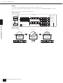 10
10
-
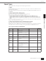 11
11
-
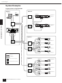 12
12
-
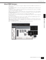 13
13
-
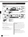 14
14
-
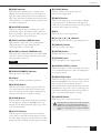 15
15
-
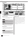 16
16
-
 17
17
-
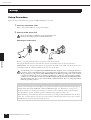 18
18
-
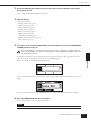 19
19
-
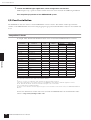 20
20
-
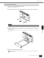 21
21
-
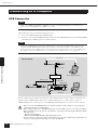 22
22
-
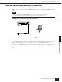 23
23
-
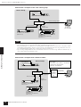 24
24
-
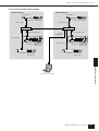 25
25
-
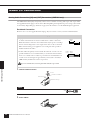 26
26
-
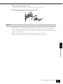 27
27
-
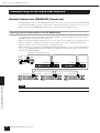 28
28
-
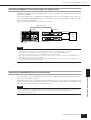 29
29
-
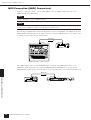 30
30
-
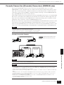 31
31
-
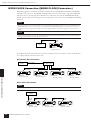 32
32
-
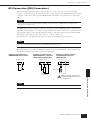 33
33
-
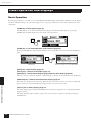 34
34
-
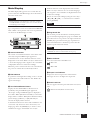 35
35
-
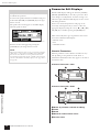 36
36
-
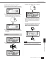 37
37
-
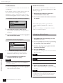 38
38
-
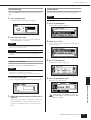 39
39
-
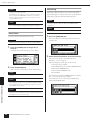 40
40
-
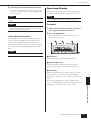 41
41
-
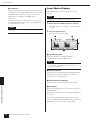 42
42
-
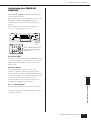 43
43
-
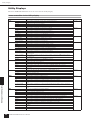 44
44
-
 45
45
-
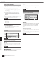 46
46
-
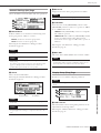 47
47
-
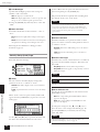 48
48
-
 49
49
-
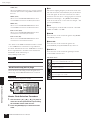 50
50
-
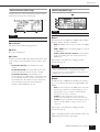 51
51
-
 52
52
-
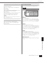 53
53
-
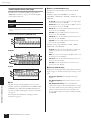 54
54
-
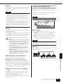 55
55
-
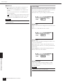 56
56
-
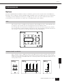 57
57
-
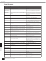 58
58
-
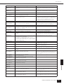 59
59
-
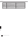 60
60
-
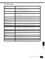 61
61
-
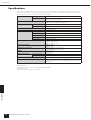 62
62
-
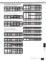 63
63
-
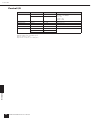 64
64
-
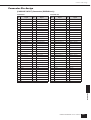 65
65
-
 66
66
-
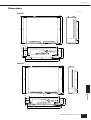 67
67
-
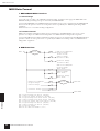 68
68
-
 69
69
-
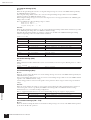 70
70
-
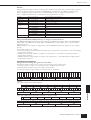 71
71
-
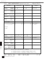 72
72
-
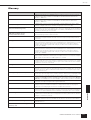 73
73
-
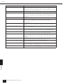 74
74
-
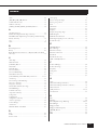 75
75
-
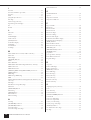 76
76
-
 77
77
-
 78
78
-
 79
79
-
 80
80


Yamaha DME24N Manual de usuario
- Categoría
- Equipo de música suplementario
- Tipo
- Manual de usuario
- Este manual también es adecuado para
en otros idiomas
- français: Yamaha DME24N Manuel utilisateur
- italiano: Yamaha DME24N Manuale utente
- English: Yamaha DME24N User manual
- Deutsch: Yamaha DME24N Benutzerhandbuch
- русский: Yamaha DME24N Руководство пользователя
- Nederlands: Yamaha DME24N Handleiding
- português: Yamaha DME24N Manual do usuário
- dansk: Yamaha DME24N Brugermanual
- polski: Yamaha DME24N Instrukcja obsługi
- čeština: Yamaha DME24N Uživatelský manuál
- svenska: Yamaha DME24N Användarmanual
- Türkçe: Yamaha DME24N Kullanım kılavuzu
- suomi: Yamaha DME24N Ohjekirja
- română: Yamaha DME24N Manual de utilizare
Artículos relacionados
-
Yamaha DME-64N Manual de usuario
-
Yamaha DME64N El manual del propietario
-
-
-
-
-
-
-
-
Otros documentos
-
Work-pro MD 82 AX MK II Manual de usuario
-
Schneider Electric HMISTO705 Manual de usuario
-
Black Box RS-232 Current Loop Interface Converter 232/CL-E Manual de usuario
-
König CMP-RCT21 Especificación
-
Tripp Lite MODBUSCARDSV Instrucciones de operación
-
Peavey MediaMatrix CAB 16i and CAB 16o El manual del propietario
-