
Bead RuptorTM 96
Well Plate Homogenizer
en User Manual
fr Manuel d’utilisation
it Manuale d’uso
es Manual del usuario
de Benutzerhandbuch

This page left blank intentionally

Data herein has been veried and validated. It is believed adequate for the intended use of the instrument.
If the instrument or procedures are used for purposes over and above the capabilities specied herein,
conrmation of the validity and suitability should be obtained; otherwise OMNI International, a PerkinElmer
company does not guarantee results and assumes no obligation or liability. This publication is not a license
to operate under, or a recommendation to infringe upon, any process patents.
This product is warranted to be free from defects in material and workmanship for a period of ONE YEAR
from the date of delivery. OMNI International, a PerkinElmer company will repair or replace and return free
of charge any part which is returned to its factory within said period, transportation prepaid by user, and
which is found upon inspection to have been defective in materials or workmanship. This warranty does
not include normal wear from use; it does not apply to any instrument or parts which have been altered by
anyone other than an employee of OMNI International, a PerkinElmer company nor to any instrument which
has been damaged through accident, negligence, failure to follow operating instructions, the use of electric
currents or circuits other than those specied on the plate axed to the instrument, misuse, or abuse.
OMNI International, a PerkinElmer company reserves the right to change, alter, modify, or improve any of its
instruments without any obligation whatever to make corresponding changes to any instrument previously
sold or shipped.
THE FORGOING OBLIGATION IS IN LIEU OF ALL OBLIGATIONS AND LIABILITIES INCLUDING NEGLIGENCE AND ALL
WARRANTIES OF MERCHANTABILITY OR OTHERWISE, EXPRESSED OR IMPLIED IN FACT OR BY LAW, AND STATE OUR ENTIRE
AND EXCLUSIVE LIABILITY AND BUYERS EXCLUSIVE REMEDY FOR ANY CLAIM OF DAMAGES IN CONNECTION WITH THE
SALE OR FURNISHING OF GOODS OR PARTS, THEIR DESIGN, SUITABILITY FOR USE, INSTALLATION, OR OPERATION. OMNI
International, a PerkinElmer company WILL IN NO EVENT BE LIABLE FOR ANY SPECIAL OR CONSEQUENTIAL DAMAGES
WHATSOEVER, AND THEIR LIABILITY UNDER NO CIRCUMSTANCES WILL EXCEED THE CONTRACT PRICE FOR THE GOODS FOR
WHICH LIABILITY IS CLAIMED.
This product has been engineered for safety; however, basic safety precautions and common sense must
always be demonstrated when using any electrical product.
- DO NOT attempt to modify any part of this product.
- DO NOT allow the machine to be submerged in any liquid.
- DO NOT use in any setting other than an indoor laboratory.
- DO NOT plug power cord into an incorrect outlet or subject it to an incorrect voltage.
- Use this product only for its intended purpose.
- DO NOT use attachments not recommended by the manufacturer.
- DO NOT operate the product if it is damaged in any way.
- Keep this product away from heated surfaces.
- DO NOT modify the plug or cord that is provided. If the plug will not t the outlet, have the proper outlet
installed by a qualied electrician.
- DO NOT operate the product with the safety ground disconnected.
WARNING: The processing chamber of the Bead RuptorTM 96 homogenizer is enclosed by a strong
covering lid. Starting of the machine is possible only with the lid closed. If the lid is open, message “LID”
appears on the display, when the START/STOP key is pressed. When message “LID” appears on display,
the lid must be closed and the error message cleared by pressing the START/STOP key. The instrument
can then be started by pressing the START/STOP key again. If the lid is opened during operation, the
machine stops rapidly and message “Er3” appears on display. When message “Er3” appears on display,
the machine cannot be restarted by pressing the START/STOP key. The main POWER switch must be
turned to OFF and then ON again, to clear the message before instrument operation can proceed.
MILLING JAR FILL REQUIREMENTS
WARNING: The sample quantity must not be less than 25% of the milling jar capacity. The milling balls
may otherwise damage the milling jars. The milling jars and milling balls must be the same material.
Otherwise the milling jar could be damaged.
WARNING: The instrument must be balanced prior to operation. Do not operate the instrument with
only one milling jar or one well plate adapter installed in a single milling jar holder. Both milling jar
holders must have either a milling jar (lled with equivalent mass) or well plate adapters. If not balanced
damage to the lid is possible.
For research use only. Not for use in diagnostic procedures.

Overview
The Bead RuptorTM 96 Homogenizer consists of the following:
Technical Data
1. Lid
2. Control Panel
3. Milling Jar holder (left)
4. Milling Jar holder (right)
5. Lid
6. On/O Switch
7. Fuse Compartment
8. Power Cord Port
1.
2.
3.
4.
5.
6.
7.
8.
Description Quantity
Bead RuptorTM 96 Homogenizer Assembly 1
Milling Wrench 2
Power Cord 1
Spare Fuse 1
User Manual 1
Power supply 230V ± 10% - 50/60Hz
115V ± 10% - 50/60Hz
Rated power 200W
Fuses 2 x 2AT 250V (230V)
2 x 5AT 250V (115V)
Vibrational frequency
regulation
Digital, from 3 to 30 Hz (180 - 1800 min-1),
in 0.1 Hz steps
Timer
5 sec - 99 min, timer HOLD function,
in 1 sec steps (below 10 min),
or 10 sec steps (above 10 min)
Max. volume of milling cups 50 ml
Max Well Plate Capacity per milling jar holder
1 X 2 ml deep well plate, 2 X 1 mL deep well plate,
3 X standard well plate, 96 1 x 1.1 or 1.4 ml 2D
barcoded storage tubes.
Dimensions W x D x H 385 x 420 x 240 mm (465 mm with hood open)
Weight 42 kg
Noise emission
(without milling balls) 70 dB(A)
Ambient temperature 5°C - 40°C
Atmospheric humidity < 85% RH

Control Panel
1. Run signal light
2. Time signal light
3. Display Screen
4. Frequency signal light
5. Control Knob
6. Start/Stop button
1.
2.
3.
4.
5.
6.
RUN
START
STOP
TIME FREQ
• RUN Signal light (green) - lit when the Bead RuptorTM 96 Homogenizer is running.
• TIME Signal light (yellow) - lit when the Bead RuptorTM 96 Homogenizer timer
selection is active.
• FREQUENCY Signal light (yellow) - lit when the Bead RuptorTM 96 Homogenizer
frequency selection is active. Frequency is dened as number of wave cycles per
second (1/s). Measured in Hz.
• CONTROL KNOB (rotate / push) - rotate right (+) Or left (-) to change the Time
or Frequency setting values. Push the Control Knob to switch between Time and
Frequency settings.
• START/STOP button - press to start or stop the cycle.
WARNING: Only start the Bead RuptorTM 96 Homogenizer with the lid in the closed
position. The display will read “LID” if the lid is open when attempting to start.
Always start and stop the Bead RuptorTM 96 with the Start/Stop button.

A A
B B
C C
A. Centering Points
B. Locking Pin
C. Knob
Milling Jars
O-Rings
Jar Wrenches
96 Well Plate And 2D Barcode 96 Well
Storage Tube Adapters
Milling Jar and Rack Holders

Inserting Milling Jars
Opening Milling Jars
• Fill milling jar with material to be milled. Ensure the two-white o-rings are in place
prior to sealing jars.
• Lift the locking pin (B) upwards from the groove and turn it 90° in any direction
to unlock.
• Turn the knob (C) counter clockwise all the way to maximize clamping range.
• Turn locking pin 90° and allow it to reengage in locked position.
• Place the milling jar into the milling jar arm and seat it into centering points (A).
• Gently turn knob (C) clockwise until the milling jar ts rmly inside the holder,
free of play.
• To remove the milling jar, lift the locking pin (B) and turn it 90° to unlock and turn
the knob (C) counter clockwise to loosen. If locking pin is dicult to release turn
knob (C) slightly clockwise to release locking pin tension.
WARNING: Always include an O-Ring when a Milling Jar is assembled to run.
WARNING: Do not force locking pin (B) open. Turn knob (C) clockwise to release.
WARNING: Milling jars must be inserted and aligned with centering points (A). If this
is not done jars may be ejected during processing.
WARNING: When removing hot or cryogenically cooled milling jars always wear
protective gloves.
WARNING: It is unlawful to mill ammable or explosive material.
• Obtain two milling jar wrenches
• Place one milling jar wrench on each end of the milling jar
• Turn one wrench counterclockwise while securing the other wrench from moving to
loosen jar seal.
• Carefully separate jar halves.

Inserting Well Plate Adapters
• Bead RuptorTM 96 Homogenizer well plate adapters can hold 1 X 2 mL deep well plate,
2 X 1 mL deep well plates or 3 X standard well plates per processing arm.
• 96 well 2D barcode storage tube adapters can hold 1 x 1.1 ml or 1 x 1.4 ml plates per
processing arm.
• Place samples and beads in the well plate.
• Fully seal the well plate with well plate mat. Care must be taken to ensure the well
plate is properly sealed. A silicon mat is recommended.
• If processing multiple well plates, stack the well plates bottom to top.
• Place the well plate adapters on the top and bottom of the well plate stack. Ensure
the adapter extensions are aligned.
• Lift the locking pin (B) upwards from the groove and turn it 90° in any direction
to unlock.
• Turn the knob (C ) counter clockwise all the way to maximize clamping range.
• Turn locking pin 90° and allow it to reengage in locked position.
• Place the well plate adapter into the milling jar arm and seat it into centering points (A).
Gently turn knob (C ) clockwise until the well plate adapter ts rmly inside the holder,
free of play.
• To remove the well plates, lift the locking pin (B) and turn it 90° to unlock and turn
the knob (C) counter clockwise to loosen. If locking pin is dicult to release, turn
knob (C) slightly clockwise to release locking pin tension.
WARNING: Do not force locking pin (B) open. Turn knob (C ) clockwise to release.
WARNING: Well plates and adapters must be inserted and aligned with centering
points (A). If this is not done the well plates may be ejected during processing.
WARNING: Milling arms must be balanced prior to operation. You must always
operate with two well plate adapters. One in each arm.
WARNING: The Bead RuptorTM 96 only accepts SPS format plates less than 49.25 mm high.

Safety instructions when working
with Liquid Nitrogen
Accessories
The Bead RuptorTM 96 Homogenizer can be operated with liquid nitrogen for cyrogenic
milling of milling jars. Milling jars can be pre-cooled in a liquid nitrogen bath then
placed on the Bead RuptorTM 96 Homogenizer for dissociation of tough materials.
Cooling times and processing times will be dependent on target material. It is highly
recommended that you follow the safety instructions for handling liquid nitrogen
provided by your liquid nitrogen provider.
WARNING: Always wear protective gloves and googles when working with liquid
nitrogen. Liquid nitrogen has a temperature of -196°C and will cause severe burns
and frostbite with skin or eye contact.
Milling Jars Order Number
Stainless Steel 25 mL - set of two
Stainless Steel 50 mL - set of two
27-004
27-006
Grinding Balls
10 mm stainless - set of ten
25 mm stainless - set of ve
27-203
27-206
Well Plate and Tube Adapters
Stainless Steel - set of two
PTFE - set of two. (Holds 48 x 0.5 - 2 mL
microcentrifuge or screw cap tubes)
27-101
27-106
96 Well 2D Barcode Storage Tube Adapters
Micronic/FluidX 1.1 and 1.4 mL
with septum style caps.
Thermo Fisher Scientic
Matrix 1.1 m L, Micronic 1.1 mL , 1.4 mL
and FluidX 1.1 and 1.4 mL storage tubes
with septum style caps.
27-107
27-108
2 mL Stainless Steel Tubes - set of two
tubes with slugs
19-6001

Replacing the Fuse
Troubleshooting
Troubleshooting
Error Possible Solution
Power Switch is not illuminated
when the Bead Ruptor 96 is on.
1. Check the power supply
2. Check fuses and replace if necessary
3. Call for service
Display screen is not working Call for service
“LID” appears on display
Indicates that the hood is open when the start button
was pressed. Close hood and clear message by pressing
the Start/Stop button. Press Start/Stop to begin cycle.
Message “Er1” appears on
display screen
Motor has over heated. Turn power o and allow motor
to cool down.
Message “Er2” appears on
display screen
The Bead Ruptor 96 is unable to reach the set vibrational
frequency. Check Milling Jars for obstructions. Switch
Power OFF and ON to clear error message.
Message “Er3” appears on
display screen
Hood was opened during operation. The power must be
turned OFF and then ON to clear error message before
operation can continue.
DO NOT: attempt to service the Bead Ruptor 96 in a manner other than
those discussed in this manual. For any issue that is unsuccessfully correct-
ed using this guide, please contact your authorized dealer or call
Omni International at 1-800-776-4431.
Replacing the Fuse
The following fuses are required for the Bead Ruptor 96:
• 2 x 2AT 250V (230V)
• 2 x 5AT 250V (115V)
• Unplug power cord from the power cord port (2).
• By pressing the locking device on the bottom side of the fuse compartment (1), fuse
holder is released and you can pull it out.
• Replace fuses.
• Insert fuse holder and push it, until it locks.
1. Fuse Compartment
2. Power Cord Port
The following fuses are required for the Bead RuptorTM 96 Homogenizer:
• 2 x 2AT 250V (230V)
• 2 x 5AT 250V (115V)
• Unplug power cord from the power cord port (2).
• By pressing the locking device on the bottom side of the fuse compartment (1), fuse
holder is released and you can pull it out.
• Replace fuses.
• Insert fuse holder and push it, until it locks.
DO NOT: attempt to service the Bead RuptorTM 96 Homogenizer in a manner other
than those discussed in this manual. For any issue that is unsuccessfully corrected
using this guide, please contact your authorized dealer or call
OMNI International, a PerkinElmer company at 1-800-776-4431.
Error Possible Solution
Power Switch is not illuminated when the Bead
RuptorTM 96 Homogenizer is on.
1. Check the power supply
2. Check fuses and replace if necessary
3. Call for service
Display screen is not working Call for service
“LID” appears on display
Indicates that the lid is open when the start
button was pressed. Close lid and clear mes-
sage by pressing the Start/Stop button. Press
Start/Stop to begin cycle.
Message “Er1” appears on display screen Motor has over heated. Turn power o and
allow motor to cool down.
Message “Er2” appears on display screen
The Bead RuptorTM 96 Homogenizer is unable
to reach the set vibrational frequency. Check
Milling Jars for obstructions. Switch Power
OFF and ON to clear error message.
Message “Er3” appears on display screen
Lid was opened during operation. The power
must be turned OFF and then ON to clear
error message before operation can continue.

fr
Les données dans la présente ont été vériées et validées Nous estimons qu’elles sont adéquates pour
l’utilisation prévue de l’instrument. Si l’instrument ou les procédures sont utilisées à des ns au-delà et
au-dessus des capacités spéciées dans la présente, la conrmation de la validité et de la pertinence doit
être obtenue ; sinon OMNI International, a PerkinElmer company ne garantira pas les résultats et n’assum-
era aucune obligation ni responsabilité. Cette publication ne constitue pas une licence d’utilisation, ni une
recommandation de violer des brevets de procédés. Ce produit est garanti exempt de défauts de matériaux
et de fabrication pendant une période d’UN AN à compter de la date de livraison. OMNI International, a
PerkinElmer company réparera ou remplacera et retournera gratuitement toute pièce qui est retournée à
son usine pendant ladite période, le transport ayant été payé par l’utilisateur, et dont les défauts de matéri-
aux et de fabrication ont été constaté par une inspection. Cette garantie ne couvre pas l’usure normale résul-
tant de l’utilisation du produit ; elle ne s’applique pas aux instruments ni aux pièces qui ont été modiés par
quiconque autre qu’un employé d’OMNI International, a PerkinElmer company, ni à tout instrument qui a
été endommagé par accident, négligence, non-respect des consignes d’utilisation, l’utilisation de courants
électriques ou de circuits autres que ceux indiqués sur la plaque apposée sur l’instrument, par une mauvaise
utilisation ou un abus. OMNI International, a PerkinElmer company se réserve le droit de changer, d’altérer,
de modier ou d’améliorer n’importe lequel de ses instruments sans aucune obligation que ce soit à apport-
er des modications correspondantes à tout instrument vendu ou expédié.
LA PRÉSENTE OBLIGATION REMPLACE TOUTE AUTRE OBLIGATION ET RESPONSABILITÉ, Y COMPRIS LA
NÉGLIGENCE ET TOUTE AUTRE GARANTIE DE QUALITÉ MARCHANDE OU AUTREMENT, EXPRESSE OU
IMPLICITE EN FAIT OU EN DROIT, ET AFFIRME NOTRE ENTIÈRE ET EXCLUSIVE RESPONSABILITÉ ET LE RECOURS
EXCLUSIF DES ACHETEURS POUR TOUTE DEMANDE DE DOMMAGES DANS LE CADRE DE LA VENTE OU
FOURNITURE DE BIENS OU DE PIÈCES, LEUR CONCEPTION, PERTINENCE POUR UTILISATION, INSTALLATION
OU FONCTIONNEMENT. OMNNI INTERNATIONAL NE SERA EN AUCUN CAS RESPONSABLE DE DOMMAGES
PARTICULIERS OU INDIRECTS QUELS QU’ILS SOIENT, ET SA RESPONSABILITÉ EN AUCUN CAS NE DÉPASSERA LE PRIX
PRÉVU DANS LE CONTRAT POUR LES PRODUITS POUR LESQUELS LA RESPONSABILITÉ EST REVENDIQUÉE.
Ce produit a été mis au point en tenant compte de la sécurité de l’opérateur ; toutefois, toujours suivre des
précautions de sécurité de base et faire preuve de bon sens lors de l’utilisation de produits électriques.
– NE PAS essayer de modier des pièces de ce produit.
– NE PAS submerger la machine dans un liquide.
– NE PAS utiliser d’autres milieux qu’un laboratoire intérieur.
– NE PAS brancher le cordon d’alimentation dans une prise inadéquate ni le soumettre à une tension incorrecte.
– Utiliser ce produit uniquement pour l’usage auquel il est destiné.
– NE PAS utiliser des accessoires non recommandés par le fabricant.
– NE PAS faire fonctionner le produit s’il a subi un dommage d’une manière ou d’une autre.
– Tenir le produit à l’écart de surfaces chauées.
– NE PAS modier la che ou le cordon fournis. Si la che ne correspond pas à la prise, demander à un
électricien qualié d’installer une prise adéquate.
– NE PAS faire fonctionner le produit avec le dispositif de mise à la terre débranché.
AVERTISSEMENT : La chambre de traitement du Bead RuptorTM 96 est fermée au moyen d’un solide
couvercle la recouvrant. Le démarrage de la machine est possible seulement si le couvercle est fermé.
Si le couvercle est ouvert, le message « LID » (couvercle) apparaîtra à l’écran, lorsque la touche START/
STOP (Commencer / Arrêter) est pressée. Lorsque le message « LID » apparaît à l’écran, le couvercle
doit être fermé et le message d’erreur eacé en appuyant sur la touche START/STOP. On peut alors
démarrer l’instrument en appuyant à nouveau sur la touche START/STOP. Si le couvercle est ouvert
au cours du fonctionnement de la machine, la machine s’arrêtera rapidement et le message « Er3
» apparaîtra à l’écran. Lorsque le message « Er3 » apparaît à l’écran, la machine ne peut pas être
redémarrée en appuyant sur la touche START/STOP. L’interrupteur principal d’ALIMENTATION doit être
mis sur la position OFF et ensuite à nouveau sur ON pour eacer le message avant que l’instrument
puisse se remettre à fonctionner.
EXIGENCES CONCERNANT LE REMPLISSAGE DU BOL DE BROYAGE
AVERTISSEMENT : La quantité de l’échantillon ne doit pas être inférieure à 25 % de la capacité du
bol de broyage. Sinon, les billes de broyage risquent d’endommager les bols de broyage. Les bols
de broyage et les billes de broyage doivent être faits du même matériau. Sinon, les bols de broyage
pourraient être endommagés.
AVERTISSSEMENT : L’instrument doit être équilibré avant de le faire fonctionner. Ne pas faire
fonctionner l’instrument avec seulement un bol de broyage ou un adaptateur de plaque multipuits
installé dans un seul support de bol de broyage. Les deux supports de bol de broyage doivent avoir
chacun un bol de broyage (chacun rempli de masse équivalente) ou des adaptateurs de plaque
multipuits. Si l’instrument n’est pas équilibré, le couvercle risque d’être endommagé.

Overview
Le Bead RuptorTM 96 est composé des éléments suivants :
Données techniques
1. Couvercle
2. Panneau de commande
3. Support de bol de broyage (gauche)
4. Support de bol de broyage (droit)
5. Couvercle
6. Interrupteur ON/OFF
7. Compartiment à fusibles
8. Port du cordon d’alimentation
1.
2.
3.
4.
5.
6.
7.
8.
Description Quantité
Ensemble Bead RuptorTM 96 1
Cordon d’alimentation 1
Fusible de rechange 1
Manuel d’utilisation 1
Alimentation électrique 230 V ± 10 % - 50/60 Hz
115 V ± 10 % - 50/60 Hz
Puissance nominale 200 W
Fusibles 2 x 2 AT 250 V (230 V)
2 x 5 AT 250 V (115 V)
Réglage de la fréquence
de vibration
Numérique, de 3 à 30 Hz (180 - 1800 min-1),
en intervalles s de 0,1 Hz
Minuterie
5 s – 99 min, fonction EN ATTENTE de la minuterie,
en intervalles d’1 seconde (moins de 10 min)
ou en intervalles de 10 s (plus de 10 min)
Volume max. des bols de broyage 50 ml
Capacité max de plaques multipuits par support
de bol de broyage
1 x plaque multipuits de 2 ml de profondeur,
2 x plaques multipuits de 1 ml de profondeur,
3 x plaques multipuits standard
Dimensions La x P x H 385 x 420 x 240 mm (465 mm avec couvercle ouvert)
Poids 42 kg
Émission de bruit (sans billes de broyage) 70 dB(A)
Température ambiante 5°C - 40°C
Humidité atmosphérique < 85% RH

Panneau de commande
1. Voyant de marche
2. Voyant de durée
3. Écran d’achage
4. Voyant de fréquence
5. Bouton de commande
6. Touche Start/Stop
1.
2.
3.
4.
5.
6.
RUN
START
STOP
TIME FREQ
• Voyant MARCHE (vert) – allumé lorsque le Bead RuptorTM 96 est en marche.
• Voyant DURÉE (jaune) – allumé lorsque la sélection de la minuterie du Bead RuptorTM
96 est active.
• Voyant FRÉQUENCE (jaune) – allumé lorsque la sélection de la fréquence du Bead
RuptorTM 96 est active. La fréquence est dénie comme le nombre d’oscillations par
seconde (1/s). Mesuré en Hz.
• BOUTON DE COMMANDE (tourner / pousser) – tourner vers la droite (+) Ou vers la
gauche (-) pour modier les valeurs de réglage de la durée ou de la fréquence. Pousser
sur le bouton de commande pour passer des réglages de la durée aux réglages de la
fréquence.
• Touche START/STOP – appuyer sur cette touche pour commencer ou arrêter le cycle.
AVERTISSEMENT : Démarrer le Bead RuptorTM 96 seulement lorsque le couvercle est
dans la position fermée. L’écran achera « LID » si le couvercle est ouvert au cours
d’une tentative de démarrage. Toujours démarrer et arrêter le Bead RuptorTM 96 à
l’aide de la touche Start/Stop.

A A
B B
C C
A. Points de centrage
B. Goupille de verrouillage
C. Molette
Bols de broyage
Joints toriques
Clés de bol
Adaptateurs de plaque
multipuits
Supports de bols de broyage et portoirs

Comment insérer les bols de broyage
Comment ouvrir les bols de broyage
• Remplir le bol de broyage de matières à broyer. S’assurer que les deux joints toriques sont
en place avant de sceller les bols.
• Soulever la goupille de verrouillage (B) vers le haut à partir de la rainure, et la faire pivoter
de 90° ans n’importe quel sens pour déverrouiller.
• Tourner la molette (C) à fond dans le sens contraire des aiguilles d’une montre pour max
imiser la plage de serrage.
• Faire pivoter la goupille de verrouillage de 90° et lui permettre de se réengager en
position verrouillée.
• Mettre le bol de broyage dans le bras de bol de broyage et le placer dans les points de centrage (A).
• Tourner doucement la molette (C) dans le sens des aiguilles d’une montre jusqu’à ce que
le bol de broyage soit fermement ajusté à l’intérieur du support, sans jeu.
• Pour enlever le bol de broyage, soulever la goupille de verrouillage (B) vers le haut et la
faire pivoter de 90° pour déverrouiller et tourner la molette (C) dans le sens contraire des
aiguilles d’une montre pour desserrer. Si la goupille de verrouillage est dicile à dégager,
tourner la molette (C) légèrement dans le sens des aiguilles d’une montre pour relâcher
la tension de la goupille de verrouillage.
AVERTISSEMENT: toujours inclure un joint torique lorsqu’un pot de fraise est assemblé
pour fonctionner.
AVERTISSEMENT : Ne pas forcer la goupille de verrouillage pour la dégager (B). Tourner la molette
(C) dans le sens des aiguilles d’une montre pour dégager la goupille.
AVERTISSEMENT : Les bols de broyage doivent être insérés et alignés sur les points de centrage
(A). Si cela n’est pas fait, les bols risquent d’être éjectés au cours du traitement.
AVERTISSEMENT : Toujours porter des gants de protection lors du retrait de bols de
broyage chauds ou refroidis cryogéniquement.
AVERTISSEMENT : Il est interdit de broyer des matières inammables ou explosives.
• Se procurer deux clés de bols de broyage
• Placer une clé de bol de broyage sur chaque extrémité du bol de broyage
• Tourner une clé dans le sens contraire des aiguilles d’une montre tout en empêchant
l’autre clé de bouger an de desserrer le joint du bol.
• Séparer soigneusement les moitiés du bol.

Comment insérer les adaptateurs
de plaque multipuits
• Les adaptateurs de plaque multipuits du Bead RuptorTM 96 peuvent tenir 1 x plaque multipuits de 2 ml
d e profondeur, 2 x plaques mul ipuits de 1 ml ou 3 x plaques multipuits standard par bras de traitement.
• Placer les échantillons et les billes dans la plaque multipuits.
• Sceller entièrement la plaque multipuits à l’aide de mat de plaque. Veiller à ce que la plaque
multipuits soit correctement scellée. Un mat en silicone est recommandé.
• En cas de traitement de plusieurs plaques multipuits, empiler les plaques multipuits de bas en haut.
• Placer les adaptateurs de plaques multipuits au sommet et au bas de la pile de plaques multipuits. Veiller à
ce que les extensions des adaptateurs soient alignées.
• Soulever la goupille de verrouillage (B) vers le haut à partir de la rainure, et la faire pivoter de 90° dans
n’importe quel sens pour déverrouiller.
• Tourner la molette (C) à fond dans le sens contraire des aiguilles d’une montre pour maximiser la plage de
serrage.
• Faire pivoter la goupille de verrouillage de 90° et lui permettre de se réengager en position verrouillée.
• Mettre l’adaptateur de plaque multipuits dans le bras de bol de broyage et le placer dans les points de
centrage (A). Tourner doucement la molette (C) dans le sens des aiguilles d’une montre jusqu’à ce que
l’adaptateur de plaque multipuits soit fermement ajusté à l’intérieur du support, sans jeu.
• Pour enlever les plaques multipuits, soulever la goupille de verrouillage (B) vers le haut et la faire pivoter
de 90° pour déverrouiller et tourner la molette (C) dans le sens contraire des aiguilles d’une montre pour
desserrer. Si la goupille de verrouillage est dicile à dégager, tourner la molette (C) légèrement dans
le sens des aiguilles d’une montre pour relâcher la tension de la goupille de verrouillage.
AVERTISSEMENT : Ne pas forcer la goupille de verrouillage pour la dégager (B). Tourner la molette (C)
dans le sens des aiguilles d’une montre pour dégager la goupille.
AVERTISSEMENT : Les plaques multipuits et les adaptateurs doivent être insérés et alignés sur les
points de centrage (A). Si cela n’est pas fait, les plaques multipuits risquent d’être éjectées au cours du
traitement.
AVERTISSEMENT : Les bras de broyage doivent être équilibrés avant tout fonctionnement de la machine.
Toujours faire fonctionner la machine avec deux adaptateurs de plaque multipuits. Un adaptateur dans
chaque bras.
AVERTISSEMENT: Le Bead RuptorTM 96 n’accepte que les plaques au format SPS de moins de 49,25 mm de
hauteur.

Consignes de sécurité lorsqu’on travaille avec
de l’azote liquide
Accessoires
Le Bead RuptoTM 96 peut être utilisé avec de l’azote liquide pour le broyage
cryogénique des bols de broyage. Les bols de broyage peuvent être prérefroidis dans
un bain d’azoteliquide et placés ensuite dans le Bead RuptorTM 96 pour la dissociation
de matières tenaces.
Les durées de refroidissement et de traitement dépendront de la matière cible. Lors de
toute manipulation d’azote liquide, il est vivement recommandé de suivre les
consignes de sécurité fournies par le fournisseur d’azote liquide.
AVERTISSEMENT : Toujours porter des gants de protection et des lunettes
de sécurité au cours de travaux avec de l’azote liquide. L’azote liquide a une
température de -196°C et provoquera des brûlures et des gelures graves en cas de
contact avec la peau ou les yeux.
Bols de broyage Order Number
Acier inoxydable 25 ml – ensemble de deux bols
Acier inoxydable 50 ml – ensemble de deux bols
27-004
27-006
Billes de broyage
Acier inoxydable 10 mm – ensemble de dix billes
Acier inoxydable 25 mm – ensemble de cinq billes
27-203
27-206
Adaptateurs de plaques multipuits et de tubes
Acier inoxydable – Ensemble de deux adaptateurs
PTFE – ensemble de deux adaptateurs (contient
48 x tubes [0,5 - 2 ml]de microcentrifugation ou à
bouchon vissé).
27-101
27-106
Adaptateurs pour tubes de stockage de codes à
barres 2D à 96 puits
Micronic/FluidX 1.1 and 1.4 mL
with septum style caps.
Thermo Fisher Scientic
Matrix 1.1 m L, Micronic 1.1 mL , 1.4 mL and FluidX
1.1 and 1.4 mL storage tubes with septum style
caps.
27-107
27-108
Tubes en acier inoxydable de 2 ml - ensemble de
deux tubes avec tampons
19-6001

Comment remplacer les fusibles
Dépannage
Troubleshooting
Error Possible Solution
Power Switch is not illuminated
when the Bead Ruptor 96 is on.
1. Check the power supply
2. Check fuses and replace if necessary
3. Call for service
Display screen is not working Call for service
“LID” appears on display
Indicates that the hood is open when the start button
was pressed. Close hood and clear message by pressing
the Start/Stop button. Press Start/Stop to begin cycle.
Message “Er1” appears on
display screen
Motor has over heated. Turn power o and allow motor
to cool down.
Message “Er2” appears on
display screen
The Bead Ruptor 96 is unable to reach the set vibrational
frequency. Check Milling Jars for obstructions. Switch
Power OFF and ON to clear error message.
Message “Er3” appears on
display screen
Hood was opened during operation. The power must be
turned OFF and then ON to clear error message before
operation can continue.
DO NOT: attempt to service the Bead Ruptor 96 in a manner other than
those discussed in this manual. For any issue that is unsuccessfully correct-
ed using this guide, please contact your authorized dealer or call
Omni International at 1-800-776-4431.
Replacing the Fuse
The following fuses are required for the Bead Ruptor 96:
• 2 x 2AT 250V (230V)
• 2 x 5AT 250V (115V)
• Unplug power cord from the power cord port (2).
• By pressing the locking device on the bottom side of the fuse compartment (1), fuse
holder is released and you can pull it out.
• Replace fuses.
• Insert fuse holder and push it, until it locks.
1. Fuse Compartment
2. Power Cord Port
Les fusibles suivants sont requis pour le Bead RuptorTM 96 :
• 2 x 2 AT 250 V (230 V)
• 2 x 5 AT 250 V (115 V)
• Débrancher le cordon d’alimentation du port du cordon d’alimentation (2).
• En appuyant sur le dispositif de verrouillage au bas du compartiment des fusibles (1),
le porte-fusibles est dégagé et peut être retiré.
• Remplacer les fusibles.
• Insérer le porte-fusibles et le pousser jusqu’à ce qu’il se verrouille en place.
NE PAS : essayer d’entretenir le Bead RuptorTM 96 d’une autre façon que celle
décrite dans ce manuel. Pour résoudre tout problème n’ayant pas pu être corrigé
à l’aide de ce guide, veuillez contacter votre revendeur agréé ou appeler Omni
International au 1-800-776-4431.
Erreur Solution possible
L’interrupteur d’alimentation n’est pas éclairé
lorsque le Bead RuptorTM 96 est sous tension.
1. Vérier l’alimentation électrique
2. Vérier les fusibles et les remplacer si nécessaire
3. Contacter le service technique
L’écran d’achage ne fonctionne pas Contacter le service technique
« LID » apparaît à l’écran
Indique que le couvercle était ouvert lorsque la
touche de démarrage a été pressée Fermer le
couvercle et eacer le message en appuyant sur
la touche Start/Stop. Appuyer sur Start/Stop pour
commencer le cycle.
Message « Er1 » apparaît à l’écran Le moteur a surchaué. Mettre hors tension et
laisser refroidir le moteur.
Message « Er2 » apparaît à l’écran
Le Bead RuptorTM 96 est incapable d’atteindre la
fréquence de vibration. Vérier la présence d’ob-
structions au niveau de bols de broyage. Mettre
hors tension et ensuite sous tension pour eacer le
message d’erreur.
Message « Er3 » apparaît à l’écran
Le couvercle a été ouvert au cours du
fonctionnement. La machine doit être mise hors
tension et ensuite sous tension pour eacer le
message d’erreur avant de pouvoir continuer à
fonctionner.
1. Compartiment à fusibles
2. Port du cordon d’alimentation

it
I dati nel presente documento sono stati vericati e validati. Si ritengono adeguati per l’uso previsto dello
strumento. Se lo strumento o le procedure vengono utilizzati per scopi che vanno al di là delle funzionalità
specicate nel presente documento, deve essere ottenuta la conferma della validità e dell’idoneità;
altrimenti OMNI International, a PerkinElmer company non garantisce i risultati e non si assume alcun
obbligo o responsabilità. Questa pubblicazione non è una licenza per operare ai sensi di, né una raccoman-
dazione di violare, qualsiasi brevetto di processo. Questo prodotto è garantito esente da vizi di origine e
fabbricazione per un periodo di UN ANNO dalla data di consegna. OMNI International, a PerkinElmer com-
pany riparerà o sostituirà e restituirà gratuitamente qualsiasi componente che viene rimandato in fabbrica
entro detto periodo, con trasporto prepagato dall’utente, e che a seguito di ispezione è stato rilevato viziato
dall’origine o nella fabbricazione. Questa garanzia non include la normale usura d’uso; non si applica a qual-
siasi strumento o componente che sia stato modicato da un soggetto diverso da un dipendente di OMNI
International, a PerkinElmer company né a qualsiasi strumento che sia stato danneggiato a causa
di incidente, negligenza, inosservanza delle istruzioni d’uso, dell’uso di correnti elettriche o circuiti diversi
da quelli indicati sulla targhetta applicata allo strumento, uso improprio o abuso. OMNI International, a
PerkinElmer company si riserva il diritto di cambiare, alterare, modicare o migliorare qualsiasi suo strumen-
to senza alcun obbligo di apportare le modiche corrispondenti a qualsiasi strumento precedentemente
venduto o spedito.
L’OBBLIGO CHE PRECEDE È A TITOLO SOSTITUTIVO IN VIA DEGLI OBBLIGHI E DELLE RESPONSABILITÀ,
INCLUSA LA NEGLIGENZA E TUTTE LE GARANZIE DI COMMERCIABILITÀ O ALTRE, ESPRESSE O IMPLICITE, DI
FATTO O DI DIRITTO E INDICA LA NOSTRA INTERA ED ESCLUSIVA RESPONSABILITÀ E IL MEZZO DI TUTELA
PER GLI ACQUIRENTI PER QUALSIASI RIVENDICAZIONE DI DANNI AD ES IN RELAZIONE ALLA VENDITA O
ALLA FORNITURA DI BENI O PARTI, LA LORO PROGETTAZIONE, L’IDONEITÀ ALL’USO, L’INSTALLAZIONE O
IL FUNZIONAMENTO. OMNI International, a PerkinElmer company NON SARÀ IN ALCUN CASO RITENUTA RESPONSABILE PER
QUALSIVOGLIA DANNO SPECIFICO O CONSEQUENZIALE, E LA SUA RESPONSABILITÀ IN NESSUN CASO SUPERERÀ IL PREZZO
CONTRATTUALE PER LE MERCI PER CUI LA RESPONSABILITÀ VIENE RIVENDICATA. Questo prodotto è stato progettato per la
sicurezza; tuttavia, le precauzioni di sicurezza di base e il buon senso devono sempre essere adottati quando si utilizzano
prodotti elettrici.
– NON cercare di modicare qualsiasi parte di questo prodotto.
– NON immergere la macchina in alcun liquido.
– NON utilizzare in ubicazioni diverse da un laboratorio interno.
– NON inserire il cavo di alimentazione in una presa non corretta né sottoporlo a una tensione non corretta.
– Utilizzare questo prodotto solo per lo scopo previsto.
– NON usare accessori non consigliati dal produttore.
– NON utilizzare il prodotto se è danneggiato in qualsiasi modo.
– Tenere il prodotto lontano da superci calde.
– NON modicare la spina o il cavo fornito. Se non si adatta alla presa a disposizione, fare installare la presa
appropriata da un elettricista qualicato.
– NON utilizzare il prodotto con la messa a terra di sicurezza disconnessa.
AVVERTENZA: La camera di lavorazione del Bead RuptorTM 96 è chiusa da un coperchio resistente.
L’avvio della macchina è possibile solo con il coperchio chiuso. Se il coperchio è aperto, il messaggio
“LID” appare sul display, quando viene premuto il tasto START/STOP. Quando sul display viene
visualizzato il messaggio “LID”, il coperchio deve essere chiuso e il messaggio di errore cancellato
premendo il tasto START/STOP. Lo strumento può quindi essere avviato premendo nuovamente
il tasto START/STOP. Se il coperchio viene aperto durante il funzionamento, la macchina si ferma
rapidamente e sul display appare il messaggio “Er3”. Quando sul display viene visualizzato il
messaggio “Er3”, la macchina non può essere riavviata premendo il tasto START/STOP. L’interruttore di
alimentazione principale deve essere spostato su OFF e poi ancora una volta su ON, per cancellare il
messaggio prima che lo strumento possa riavviarsi.
REQUISITI DI RIEMPIMENTO DEL CONTENITORE DI MACINAZIONE
AVVERTENZA: La quantità del campione non deve essere inferiore al 25% della capacità del
contenitore di macinazione. Le sfere di macinazione altrimenti potrebbero danneggiare i contenitori
per la macinazione. I contenitori e le sfere per la macinazione devono essere dello stesso materiale. In
caso contrario il contenitore per la macinazione potrebbe danneggiarsi.
AVVERTENZA: Lo strumento deve essere bilanciato prima del funzionamento. Non azionare lo strumento
con un solo contenitore per la macinazione o un adattatore per la piastra a pozzetti installato in un solo
supporto del contenitore per la macinazione. Entrambi i supporti del contenitore per la macinazione
devono avere un contenitore per la macinazione (riempito con una massa equivalente) o degli adattatori
per la piastra a pozzetti. Se non è bilanciato possono vericarsi danni al coperchio.

Panoramica
Il Bead RuptorTM 96 comprende:
Dati tecnici
1. Coperchio
2. Pannello di controllo
3. Portacontenitore per la macinazione (a sinistra)
4. Portacontenitore per la macinazione (a destra)
5. Coperchio
6. Interruttore ON/OFF
7. Scomparto fusibili
8. Portello per il cavo di alimentazione
1.
2.
3.
4.
5.
6.
7.
8.
Descrizione Quantità
Assemblaggio Bead RuptorTM 96 1
Cavo di alimentazione 1
Fusibile di ricambio 1
Manuale utente 1
Alimentazione 230V ± 10% - 50/60Hz
115V ± 10% - 50/60Hz
Potenza nominale 200W
Fusibili 2 x 2AT 250V (230V)
2 x 5AT 250V (115V)
Frequenza vibrazionale
disposizione
Digitale, da 3 a 30 Hz (180 - 1800 min-1),
con incrementi di 0,1 Hz
Timer
5 sec - 99 min., timer con funzione HOLD,
con incrementi di 1 secondo (sotto i 10 min.),
o con incrementi di 10 sec (sopra i 10 min.)
Max. volume of milling cups 50 ml
Max. volume dei contenitori per la macinazione 1 x 2 ml piastra a pozzetti profondi, 2 X 1 mL piastra
a pozzetti profondi, 3 X piastra a pozzetti standard
Dimensioni [L x P x A] 385 x 420 x 240 mm (465 mm con coperchio aperto)
Peso 42 kg
Emissione sonora
(senza sfere di macinazione) 70 dB(A)
Temperatura ambientale 5°C - 40°C
Umidità atmosferica < 85% RH

Pannello di controllo
1. Luce di segnalazione di funzionamento
2. Luce di segnalazione del tempo
3. Schermo del display
4. Luce di segnale di frequenza
5. Manopola di comando
6. Tasto START/STOP
1.
2.
3.
4.
5.
6.
RUN
START
STOP
TIME FREQ
• FUNZIONAMENTO - acceso quando il Bead RuptorTM 96 è in funzione.
• Segnale luminoso (giallo) del TEMPO - acceso quando la selezione del tempo per
Bead RuptorTM 96 è attiva.
• Segnale luminoso (giallo) di FREQUENCY acceso quando la selezione della frequenza
per Bead RuptorTM 96 è attiva. La frequenza è denita come numero di cicli al secon
do(1/s). Misurata in Hz.
• MANOPOLA DI COMANDO (ruotare/spingere) - ruotare a destra (+) o a sinistra (-) per
modicare i valori di impostazione del tempo o della frequenza. Premere la manopo
la di comando per cambiare dalle impostazioni di tempo a quelle di frequenza.
• Tasto START/STOP - premere per avviare o arrestare il ciclo.
AVVERTENZA: Avviare il Bead RuptorTM 96 solo con il coperchio in posizione chiusa.
Se il coperchio è aperto quando si tenta di avviare, il display visualizzerà “LID”.
Avviare e interrompere il Bead RuptorTM 96 con il tasto Start/Stop.

A A
B B
C C
A. Punti di centraggio
B. Perno di serraggio
C. Manopola
Contenitori per
la macinazione
O-Rings
Chiavi del contenitore
Adattatori della piastra
a pozzetti
Contenitore per la macinazione e supporti
per i cestelli

Inserimento dei contenitori per la macinazione
Apertura dei contenitori per la macinazione
• Riempire il contenitore per la macinazione con il materiale da macinare. Assicurarsi
che i due o-ring bianchi siano al loro posto prima di sigillare i contenitori.
• Sollevare il perno di bloccaggio (B) verso l’alto dalla scanalatura e ruotarla di 90° in
qualsi asi direzione per sbloccare.
• Ruotare la manopola (C) in senso orario no a massimizzare la capacità di serraggio.
• Girare il perno di bloccaggio a 90° e consentire di avviare in posizione bloccata.
• Posizionare il contenitore per la macinazione nel braccio per il contenitore per la maci
nazione e bloccarlo nei punti (A) di centraggio.
• Ruotare delicatamente la manopola (C) in senso orario no a quando il contenitore
per la macinazione si adatta saldamente all’interno del supporto, senza gioco.
• Per rimuovere il contenitore per la macinazione sollevare il perno di bloccaggio (B) e
ruotarlo di 90° per sbloccare e ruotare la manopola (C) in senso orario per allentare.
Se il perno di bloccaggio è dicile da rilasciare ruotare leggermente la manopola (C)
in senso orario per rilasciare la tensione del perno di bloccaggio.
AVVERTENZA: includere sempre un O-Ring quando un vaso di fresatura viene assemblato per
eseguire.
AVVERTENZA: Non forzare il perno di bloccaggio (B) sulla posizione aperta. Ruotare la manopola
(C) in senso antiorario per rilasciare.
AVVERTENZA: I contenitori per la macinazione devono essere inseriti e allineati con i punti
di centraggio (A). Se questo non viene fatto i contenitori possono essere espulsi durante il
funzionamento.
AVVERTENZA: Quando si rimuovono i contenitori per la macinazione caldi o rareddati
criogenicamente indossare sempre i guanti protettivi.
AVVERTENZA: È illegale macinare materiale inammabile o esplosivo.
• Ottenere due chiavi del contenitore di macinazione
• Inserire una chiave del contenitore per la macinazione su ciascuna estremità del
contenitore per la macinazione
• Ruotare in senso antiorario una chiave assicurandosi che l’altra chiave non si muova
per allentare il sigillo del contenitore.
• Separare con cura le due parti del contenitore.

Inserimento degli adattatori della piastra
a pozzetti
• Gli adattatori della piastra a pozzetti del Bead RuptorTM 96 possono contenere una piastra
a pozzetti 1 X 2 mL, delle piastre a pozzetti 2 X 1 mL o 3 X piastra a pozzetti standard per
il braccio di lavorazione.
• Posizionare i campioni e le sfere nella piastra a pozzetti.
• Sigillare completamente la piastra a pozzetti con il tappetino per piastre. Occorre prestare
attenzione anché la piastra a pozzetti sia opportunamente sigillata. È consigliato un
tappetino in silicone.
• Se vengono lavorate piastre a pozzetti multipli, impilare le piastre a pozzetti dal basso
verso l’alto.
• Posizionare gli adattatori della piastra a pozzetti sulla parte inferiore e superiore della pila
della piastra a pozzetti. Assicurarsi che le estensioni dell’adattatore siano allineate.
• Sollevare il perno di bloccaggio (B) verso l’alto dalla scanalatura e ruotarla di 90° in
qualsiasi direzione per sbloccare.
• Ruotare la manopola (C) in senso orario no a massimizzare la capacità di serraggio.
• Girare il perno di bloccaggio a 90° e consentire di avviare in posizione bloccata.
• Posizionare l’adattatore della piastra a pozzetti nel braccio per il contenitore per la
macinazione e bloccarlo nei punti di centraggio (A). Ruotare delicatamente la manopola
(C) in senso orario no a quando gli adattatori della piastra a pozzetti si adattano
saldamente all’interno del supporto, senza gioco.
• Per rimuovere le piastre a pozzetti sollevare il perno di bloccaggio (B) e ruotarlo di 90° per
sbloccare e ruotare la manopola (C) in senso orario per allentare. Se il perno di
bloccaggio è dicile da rilasciare, ruotare leggermente la manopola (C) in senso orario
per rilasciare la tensione del perno di bloccaggio.
AVVERTENZA: Non forzare il perno di bloccaggio (B) sulla posizione aperta. Ruotare la manopola (C) in
senso antiorario per rilasciare.
AVVERTENZA: Gli adattatori e le piastre a pozzetti devono essere inseriti e allineati con i punti di
centraggio (A). Se questo non viene fatto le piastre a pozzetti possono essere espulse durante il
funzionamento.
AVVERTENZA: I bracci per la macinazione devono essere bilanciati prima del
funzionamento. È sempre necessario mettere in funzione due adattatori della piastra a pozzetti. Uno
in ogni braccio.
AVVERTENZA: il Bead RuptorTM 96 accetta solo lastre in formato SPS di altezza inferiore a 49,25 mm.

Istruzioni di sicurezza quando si lavora con
azoto liquido
Accessori
Il Bead RuptorTM 96 può essere azionato da azoto liquido per la macinazione criogenica
di contenitori per la macinazione. I contenitori per la macinazione possono essere
prerareddati in un bagno di azoto liquido poi inseriti sul Bead RuptorTM 96 per la
separazione delle materie dure. I tempi di rareddamento e i tempi di lavorazione
dipenderanno dal materiale. Si consiglia vivamente di seguire le istruzioni di sicurezza
per la gestione dell’azoto liquido fornito dal suo fornitore di azoto liquido.
AVVERTENZA: Indossare sempre occhiali e guanti protettivi quando si lavora
con l’azoto liquido. L’azoto liquido ha una temperatura di 196°C e causerà gravi
ustioni e congelamento in caso di contatto con pelle o con gli occhi.
Contenitori per la macinazione Numero di ordine
In acciaio inox 25 mL - set di due
In acciaio inox 50 mL - set di due
27-004
27-006
Sfere di macinazione
10 mm inox - set di dieci
25 mm inox - set di cinque
27-203
27-206
Piastra a pozzetti e adattatori a tubo
In acciaio inox- set di due
PTFE - set di due. (Contiene 48 x 0,5-2 mL
tubi per microcentrifuga o con tappo a
vite)
27-101
27-106
Adattatori per provette per stoccaggio di
codici a barre a 96 pozzetti
Micronic/FluidX 1.1 and 1.4 mL
with septum style caps.
Thermo Fisher Scientic
Matrix 1.1 m L, Micronic 1.1 mL , 1.4 mL
and FluidX 1.1 and 1.4 mL storage tubes
with septum style caps.
27-107
27-108
Tubi in acciaio inossidabile da 2 ml - set
di due tubi con proiettili
19-6001

Sostituzione del fusibile
Risoluzione dei problemi
Troubleshooting
Error Possible Solution
Power Switch is not illuminated
when the Bead Ruptor 96 is on.
1. Check the power supply
2. Check fuses and replace if necessary
3. Call for service
Display screen is not working Call for service
“LID” appears on display
Indicates that the hood is open when the start button
was pressed. Close hood and clear message by pressing
the Start/Stop button. Press Start/Stop to begin cycle.
Message “Er1” appears on
display screen
Motor has over heated. Turn power o and allow motor
to cool down.
Message “Er2” appears on
display screen
The Bead Ruptor 96 is unable to reach the set vibrational
frequency. Check Milling Jars for obstructions. Switch
Power OFF and ON to clear error message.
Message “Er3” appears on
display screen
Hood was opened during operation. The power must be
turned OFF and then ON to clear error message before
operation can continue.
DO NOT: attempt to service the Bead Ruptor 96 in a manner other than
those discussed in this manual. For any issue that is unsuccessfully correct-
ed using this guide, please contact your authorized dealer or call
Omni International at 1-800-776-4431.
Replacing the Fuse
The following fuses are required for the Bead Ruptor 96:
• 2 x 2AT 250V (230V)
• 2 x 5AT 250V (115V)
• Unplug power cord from the power cord port (2).
• By pressing the locking device on the bottom side of the fuse compartment (1), fuse
holder is released and you can pull it out.
• Replace fuses.
• Insert fuse holder and push it, until it locks.
1. Fuse Compartment
2. Power Cord Port
I fusibili seguenti sono necessari per il Bead RuptorTM 96:
• 2 x 2AT 250V (230V)
• 2 x 5AT 250V (115V)
• Scollegare il cavo di alimentazione dalla porta del cavo di alimentazione (2).
• Premendo il dispositivo di bloccaggio sul lato inferiore del vano fusibile (1),
portafusibile viene rilasciato e si può tirare.
• Sostituire i fusibili.
• Inserire il portafusibile e spingere, nché non si blocca.
COSE DA NON FARE: tentare di riparare il Bead RuptorTM 96 in modo diverso da
quello descritto in questo manuale. per qualsiasi problema che non si riesce a
risolvere utilizzando questa guida, si prega di contattare il proprio rivenditore o
chiamare OMNI International, a PerkinElmer company allo 1-800-776-4431.
Errore Possible Solution
L’interruttore di accensione non si illumina quando
il Bead RuptorTM 96 è acceso.
1. Vericare l’alimentazione elettrica.
2. Controllare i fusibili e sostituirli se necessario.
3. Chiamare l’assistenza
Il display non funziona Chiamare l’assistenza
Sul display appare “LID”.
Indica che il coperchio è aperto quando è stato
premuto il tasto Start. Chiudere il coperchio e
cancellare il messaggio premendo il tasto Start/
Stop. Premere Start/Stop per iniziare il ciclo.
Il messaggio “Er1” compare sul display Il motore si è surriscaldato. Spegnere l’alimen-
tazione e attendere che il motore si rareddi.
Il messaggio “Er2” compare sul display
Il Bead RuptorTM 96 non è in grado di raggi-
ungere la frequenza vibrazionale impostata.
Vericare il contenitore per la macinazione
alla ricerca di ostruzioni. Posizionare l’interrut-
tore su OFF e ON per cancellare il messaggio
di errore.
Il messaggio “Er3” compare sul display
Il coperchio è stato aperto durante il funzion-
amento. L’alimentazione deve essere su OFF e
poi su ON per cancellare il messaggio di errore
prima di procedere con l’operazione.
1. Scomparto fusibili
2. Portello per il cavo di alimentazione

es
Los datos del presente documento se han vericado y validado. Se consideran adecuados para la
utilización prevista del instrumento. Si el instrumento o los procedimientos se utilizan para propósitos más
allá y por encima de las capacidades especicadas aquí, deberá obtenerse conrmación de la validez e
idoneidad; de lo contrario, OMNI International, a PerkinElmer company no garantiza los resultados y no
asume ninguna obligación o responsabilidad. Esta publicación no es una licencia para operar bajo cualquier
patente de proceso, ni una recomendación para infringirlas.
Se garantiza que este producto está libre de defectos en materiales y mano de obra durante un período
de UN AÑO desde la fecha de su entrega. OMNI International, a PerkinElmer company reparará o reempla-
zará y devolverá sin cargo cualquier pieza que se devuelva a su fábrica dentro de dicho período, transporte
prepagado por el usuario, y que al inspeccionarse se determine que haya tenido un defecto en materiales
o en mano de obra. Esta garantía no incluye el desgaste normal debido al uso; no se aplica a ningún instru-
mento o pieza que hayan sido alteradas por alguna persona que no sea empleada de OMNI International, a
PerkinElmer company, ni a ningún instrumento que haya sido dañado por accidente, negligencia, incum-
plimiento de las instrucciones de operación, el uso de corrientes eléctricas o circuitos distintos de los espe-
cicados en la placa que está jada en el instrumento, mal uso o maltrato. OMNI International, a PerkinElmer
company se reserva el derecho de cambiar, alterar, modicar o mejorar cualquiera de sus instrumentos sin
compromiso alguno para hacer los cambios correspondientes a cualquier instrumento vendido o enviado
previamente.
LA ANTERIOR OBLIGACIÓN REEMPLAZA TODAS LAS OBLIGACIONES Y RESPONSABILIDADES LEGALES,
INCLUYENDO LA NEGLIGENCIA Y CUALQUIER GARANTÍA DE COMERCIABILIDAD O DE OTRO TIPO, EXPRESA
O IMPLÍCITA DE HECHO O POR DERECHO, Y ESTIPULA NUESTRA RESPONSABILIDAD ENTERA Y EXCLUSIVA,
Y LA REPARACIÓN EXCLUSIVA DEL COMPRADOR EN CASO DE CUALQUIER RECLAMACIÓN POR DAÑOS Y
PERJUICIOS EN RELACIÓN CON LA VENTA O SUMINISTRO DE BIENES O PIEZAS, SU DISEÑO, LA IDONEIDAD
PARA EL USO, LA INSTALACIÓN O LA OPERACIÓN. OMNI International, a PerkinElmer company NO SERÁ EN
NINGÚN CASO
RESPONSABLE POR NINGÚN DAÑO ESPECIAL O CONSECUENTE, Y SU RESPONSABILIDAD NO SUPERARÁ,
BAJO NINGUNA CIRCUNSTANCIA, EL PRECIO DEL CONTRATO POR LOS BIENES POR CUYA RESPONSABILIDAD
SE RECLAMA.
Este producto ha sido diseñado para ser seguro; sin embargo, siempre deben exhibirse las precauciones
básicas de seguridad y sentido común cuando se utilice cualquier aparato eléctrico.
– NO intente modicar ninguna parte de este producto.
– NO permita que la máquina se sumerja en ningún líquido.
– NO lo utilice en ningún entorno que no sea un laboratorio bajo techo.
– NO conecte el cable de alimentación en un enchufe incorrecto ni lo someta a un voltaje incorrecto.
– Utilice este producto solamente para el propósito para el que está destinado.
– NO use accesorios que no estén recomendados por el fabricante.
– NO haga funcionar el producto si está dañado de cualquier manera.
– Mantenga este producto alejado de supercies calientes.
– NO modique el enchufe o el cable que se suministra. Si la clavija no se ajusta al enchufe, pida a un
electricista cualicado que instale un enchufe adecuado.
– NO haga funcionar el producto con la tierra de seguridad desconectada.
ADVERTENCIA: La cámara de procesamiento de la Bead RuptorTM 96 está rodeada por una fuerte
tapa de cubierta. Sólo es posible arrancar la máquina con la tapa cerrada. Si la tapa está abierta,
aparece el mensaje “LID” en la pantalla cuando se presiona la tecla START/STOP. Cuando aparezca
el mensaje “LID” en la pantalla, la tapa debe cerrarse y se debe borrar el mensaje de error pulsando
la tecla START/STOP. El instrumento puede iniciarse entonces pulsando de nuevo la tecla START/
STOP. Si se abre la tapa durante el funcionamiento, la máquina se detiene rápidamente y el mensaje
“Er3” aparece en la pantalla. Cuando aparezca el mensaje “Er3” en la pantalla, la máquina no puede
reiniciarse pulsando la tecla START/STOP. El interruptor principal de alimentación debe girarse a la
posición OFF y luego de nuevo a ON para borrar el mensaje antes de que pueda proceder la operación
del instrumento. REQUISITOS DE LLENADO DE LOS RECIPIENTES DE MOLIENDA
ADVERTENCIA: La cantidad de muestra no debe ser menos del 25% de la capacidad del recipiente
de molienda. De otro modo, las bolas de molienda pueden dañar los recipientes de molienda. Los
recipientes de molienda y bolas de molienda deben ser del mismo material. En caso contrario, el
recipiente de molienda podría sufrir daños.
ADVERTENCIA: El instrumento debe equilibrarse antes de la operación. No haga funcionar el
instrumento con solamente un recipiente de molienda o un adaptador de placa de pozos instalados en
un solo soporte de recipiente de molienda. Ambos soportes de recipientes de molienda deben tener
ya sea un recipiente de molienda (llenado con una masa equivalente) o bien adaptadores de placas de
pozos. Si no está equilibrado, es posible que la tapa se dañe.

Descripción general
El Bead RuptorTM 96 consta de lo siguiente:
Datos técnicos
1. Tapa
2. Panel de control
3. Soporte de recipiente de molienda (izquierdo)
4. Soporte de recipiente de molienda (derecho)
5. Tapa
6. Interruptor de encendido y apagado
7. Portafusibles
8. Puerto del cable de alimentación
1.
2.
3.
4.
5.
6.
7.
8.
Descripción Cantidad
Ensamblado del Bead RuptorTM 96 1
Cable de alimentación 1
Fusible de repuesto 1
Manual del usuario 1
Fuente de alimentación 230V ± 10% - 50/60Hz
115V ± 10% - 50/60Hz
Potencia nominal 200W
Fusibles 2 x 2AT 250V (230V)
2 x 5AT 250V (115V)
Regulación de
frecuencia vibratoria
Digital, from 3 to 30 Hz (180 - 1800 min-1),
in 0.1 Hz steps
Temporizador 5 seg - 99 min, función de ESPERA del temporizador,
en pasos de 1 seg (por debajo de los 10 min),
o pasos de 10 seg (por encima de los 10 min),
Volumen máx. de los recipientes de molienda 50 ml
Capacidad máxima de placas de pozos por
cada soporte de recipientes de molienda
11 placa de pozos de 2 mL de profundidad, 2 placas de
pozos de 1 mL de profundidad,
3 placas de pozos estándar
Dimensiones An x Prf x Al 385 x 420 x 240 mm (465 mm con la cubierta abierta)
Peso 42 kg
Emisión de ruido
(sin bolas de molienda) 70 dB(A)
Temperatura ambiente 5°C - 40°C
Humedad atmosférica < 85% RH

Panel de control
1. Lámpara de señal de funcionamiento
2. Lámpara de señal de tiempo
3. Pantalla
4. Lámpara de señal de frecuencia
5. Perilla de control
6. Botón Start/Stop
1.
2.
3.
4.
5.
6.
RUN
START
STOP
TIME FREQ
• FUNCIONAMIENTO Luz de señal (verde) - se enciende cuando está funcionando el
Bead RuptorTM 96.
• TIEMPO Luz de señal (amarilla) - se enciende cuando la selección del temporizador
del Bead RuptorTM 96 está activa.
• FRECUENCIA Luz de señal (amarilla) - se enciende cuando la selección de
frecuencia del Bead RuptorTM 96 está activa. La frecuencia se dene como número
de ciclos de onda por segundo (1/s). Medido en Hz.
• PERILLA DE CONTROL (girar/empujar) - gire a la derecha (+) o a la izquierda (-) para
cambiar los valores de ajuste de Tiempo o de Frecuencia. Presione la perilla de con
trol para alternar entre los ajustes de tiempo y frecuencia.
• Botón START/STOP pulse para iniciar o parar el ciclo.
ADVERTENCIA: Sólo arranque el Bead RuptorTM 96 con la tapa en posición cerrada.
La pantalla mostrará “LID” si la tapa está abierta al intentar arrancar. Siempre
inicie y detenga el Bead RuptorTM 96 con el botón Start/Stop.

A A
B B
C C
A. Puntos de centrado
B. Perno de bloqueo
C. Perilla
Recipientes de molienda
Juntas tóricas
Llaves de recipientes
Adaptadores de placasde pozos
Soportes de recipientes de molienda y anaquel

Insertar recipientes de molienda
Abrir los recipientes de molienda
• Llene el recipiente de molienda con el material a ser molido. Asegúrese de que las dos
juntas tóricas blancas estén en su sitio antes de sellar los recipientes.
• Levante el perno de bloqueo (B) hacia arriba desde la ranura y gírelo 90° en cualquier
dirección para desbloquearlo.
• Gire la perilla (C) hacia la izquierda completamente para aumentar al máximo el intervalo
de sujeción.
• Gire el perno de bloqueo 90° y deje que vuelva a ajustarse en la posición de bloqueo.
• Coloque el recipiente de molienda en el brazo de recipientes de molienda y asiéntelo en
los puntos de centrado (A).
• Suavemente, gire la perilla (C) hacia la derecha hasta que el recipiente de molienda se
ajuste rmemente en el soporte, sin que haya juego.
• Para retirar el recipiente de molienda, levante el perno de bloqueo (B), gírelo 90° para
desbloquearlo y gire la perilla (C) hacia la izquierda para aojarla. Si es difícil liberar el
peno de bloqueo, gire la perilla (C) un poco hacia la derecha para liberar la tensión del
perno de bloqueo.
ADVERTENCIA: Siempre incluya un O-Ring cuando un frasco de fresado se ensambla para funcionar.
ADVERTENCIA: No fuerce el perno de bloqueo (B) para abrirlo. Gire la perilla (C) hacia la
derecha para liberarla.
ADVERTENCIA: Los recipientes de molienda deben insertarse y alinearse con los puntos
de centrado (A). Si esto no se hace, los recipientes de molienda pueden ser expulsados
durante el procesamiento.
ADVERTENCIA: Al retirar los recipientes de molienda calientes o enfriados
criogénicamente, siempre use guantes de protección.
ADVERTENCIA: Es ilegal moler material inamable o explosivo.
• Obtenga dos llaves para recipientes de molienda
• Coloque una llave de recipientes de molienda en cada extremo del recipiente
• Gire una llave hacia la izquierda al tiempo que ja la otra llave para moverla aojando
el sello del recipiente.
• Separe cuidadosamente las mitades del recipiente.

Insertar los adaptadores de placas de pozos
• Los adaptadores de las placas de pozos del Bead RuptorTM 96 pueden contener 1 placa de
pozos de 2 mL de profundidad, 2 placas de pozos de 1 mL de profundidad o 3 placas de
pozos estándar en cada brazo de procesamiento.
• Coloque las muestras y las cuentas en la placa de pozos.
• Selle completamente la placa de pozos con la estera de placa de pozos. Debe tenerse
cuidado para asegurarse de que la placa de pozos esté correctamente sellada. Se
recomienda una estera de silicona.
• Si se están procesando múltiples placas de pozos, apílelas desde la parte de abajo hacia arriba.
• Coloque los adaptadores de las placas de pozos en la parte superior e inferior de la pila
de placas de pozos. Asegúrese de que las extensiones de los adaptadores estén
alineadas.
• Levante el perno de bloqueo (B) hacia arriba desde la ranura y gírelo 90° en cualquier
dirección para desbloquearlo.
• Gire la perilla (C) hacia la izquierda completamente para aumentar al máximo el intervalo
de sujeción.
• Gire el perno de bloqueo 90° y deje que vuelva a ajustarse en la posición de bloqueo.
• Coloque el adaptador de las placas de pozos en el brazo del recipiente de molienda y
asiéntelo en los puntos de centrado (A). Gire suavemente la perilla (C) hacia la derecha
hasta que el adaptador de las placas de pozos se ajuste rmemente en el soporte, sin
que haya juego.
• Para retirar las placas de pozos, levante el pasador de bloqueo (B), gírelo 90° para
desbloquearlo y gire la perilla (C) hacia la izquierda para aojarla. Si es difícil liberar el
perno de bloqueo, gire la perilla (C) ligeramente hacia la derecha para liberar la tensión
del perno de bloqueo.
ADVERTENCIA: No fuerce el perno de bloqueo (B) para abrirlo. Gire la perilla (C) hacia la derecha para liberarla.
ADVERTENCIA: Las placas de pozos y los adaptadores deben insertarse y alinearse con los puntos de
centrado (A). Si esto no se hace, las placas de pozos pueden ser expulsadas durante el procesamiento.
ADVERTENCIA: Los brazos de molienda deben equilibrarse antes de la operación. Siempre debe operar
con dos adaptadores de placa de pozos. Uno en cada brazo.
ADVERTENCIA: El Bead RuptorTM 96 solo acepta planchas de formato SPS de menos de 49,25 mm de
altura.

Instrucciones de seguridad al trabajar con
nitrógeno líquido
Accesorios
El Bead RuptorTM 96 puede utilizarse con nitrógeno líquido para la molienda criogénica
de recipientes de molienda. Los recipientes de molienda pueden preenfriarse en un
baño de nitrógeno líquido y luego colocarse en el Bead RuptorTM 96 para disociar
materiales resistentes. Los tiempos de enfriado y los de procesamiento dependerán
del material objetivo. Se recomienda vivamente que siga las instrucciones de
seguridad para el manejo de nitrógeno líquido que ha suministrado su proveedor de
nitrógeno líquido.
ADVERTENCIA: Siempre use guantes y gafas protectores cuando trabaje con
nitrógeno líquido. El nitrógeno líquido tiene una temperatura de -196 ºC y provoca
graves quemaduras y congelación al entran en contacto con la piel o los ojos.
Recipientes de molienda Número de pedido
Acero inoxidable 25 mL - juego de dos
Acero inoxidable 50 mL - juego de dos
27-004
27-006
Bolas de molienda
10 mm de acero inoxidable - juego de diez
25 mm de acero inoxidable - juego de cinco
27-203
27-206
Placa de pozos y adaptadores de tubo
Acero inoxidable - juego de dos
PTFE - juego de dos. (Contiene 48 tubos
microcentrífugos o de tapón de rosca de
0.5 - 2 mL)
27-101
27-106
Adaptadores de tubo de almacenamiento
de código de barras 2D de 96 pocillos
Micronic/FluidX 1.1 and 1.4 mL
with septum style caps.
Thermo Fisher Scientic
Matrix 1.1 m L, Micronic 1.1 mL , 1.4 mL and
FluidX 1.1 and 1.4 mL storage tubes with
septum style caps.
27-107
27-108
Tubos de acero inoxidable de 2 ml: juego
de dos tubos con tacos
19-6001

Reemplazo del fusible
Resolución de problemas
Troubleshooting
Error Possible Solution
Power Switch is not illuminated
when the Bead Ruptor 96 is on.
1. Check the power supply
2. Check fuses and replace if necessary
3. Call for service
Display screen is not working Call for service
“LID” appears on display
Indicates that the hood is open when the start button
was pressed. Close hood and clear message by pressing
the Start/Stop button. Press Start/Stop to begin cycle.
Message “Er1” appears on
display screen
Motor has over heated. Turn power o and allow motor
to cool down.
Message “Er2” appears on
display screen
The Bead Ruptor 96 is unable to reach the set vibrational
frequency. Check Milling Jars for obstructions. Switch
Power OFF and ON to clear error message.
Message “Er3” appears on
display screen
Hood was opened during operation. The power must be
turned OFF and then ON to clear error message before
operation can continue.
DO NOT: attempt to service the Bead Ruptor 96 in a manner other than
those discussed in this manual. For any issue that is unsuccessfully correct-
ed using this guide, please contact your authorized dealer or call
Omni International at 1-800-776-4431.
Replacing the Fuse
The following fuses are required for the Bead Ruptor 96:
• 2 x 2AT 250V (230V)
• 2 x 5AT 250V (115V)
• Unplug power cord from the power cord port (2).
• By pressing the locking device on the bottom side of the fuse compartment (1), fuse
holder is released and you can pull it out.
• Replace fuses.
• Insert fuse holder and push it, until it locks.
1. Fuse Compartment
2. Power Cord Port
Se requieren los fusibles siguientes para el Bead RuptorTM 96:
• 2 x 2AT 250V (230V)
• 2 x 5AT 250V (115V)
• Desconecte el cable de alimentación del puerto del cable de alimentación (2)
• Al presionar el dispositivo de cierre en la parte inferior del compartimiento de los
fusibles(1), el portafusibles se libera y se puede sacar.
• Reemplace los fusibles.
• Inserte el portafusibles y empújelo hasta que encaje.
NO: intente reparar el Bead RuptorTM 96 de modo distinto de los expuestos en este
manual. Para cualquier problema que no se corrija con éxito usando esta guía,
comuníquese con su distribuidor autorizado o llame a OMNI International, a
PerkinElmer company al 1-800-776-4431.
Error Possible Solution
El interruptor de alimentación no está iluminado
cuando el Bead RuptorTM 96 está encendido.
1. Compruebe la fuente de alimentación
2. Compruebe los fusibles y reemplácelos si es necesario
3. Pida servicio
La pantalla no funciona Pida servicio
“LID” aparece en pantalla
Indica que la tapa está abierta cuando se presiona
el botón de inicio. Cierre la tapa y elimine el mensaje
oprimiendo el botón de Inicio/Parada. Oprima
Inicio/Parada para comenzar el ciclo.
El mensaje “Er1” aparece en la pantalla El motor se ha sobrecalentado. Apague la ali-
mentación y permita que el motor se enfríe.
El mensaje “Er2” aparece en la pantalla
El Bead RuptorTM 96 no puede llegar a la frecuencia
vibracional ajustada. Compruebe que los recipientes
de molienda no tengan obstrucciones. Apague
y encienda la alimentación para borrar el mensaje
de error.
El mensaje “Er3” aparece en la pantalla
La tapa estaba abierta durante el funcionamiento.
Debe apagarse la alimentación y después encenderse
para eliminar el mensaje de error antes de
que pueda continuar la operación.
1. Portafusibles
2. Puerto del cable de alimentación

de
Die hierin enthaltenen Daten wurden veriziert und validiert. Sie werden als für die vorgesehene
Verwendung des Instruments als geeignet erachtet. Sollten das Instrument oder die Verfahren für Zwecke
verwendet werden, die außerhalb der hier angegebenen Funktionen liegen, sollte eine Bestätigung der
Validität und Eignung eingeholt werden; andernfalls gewährleistet OMNI International, a PerkinElmer company keine Ergeb-
nisse und übernimmt keine Verpichtung oder Haftung. Dieses Schriftstück stellt keine Gewährung einer Lizenz und
keine Empfehlung zur Verletzung von Verfahrenspatenten dar. Für dieses Produkt gilt eine Gewährleistung gegen Material-
und Verarbeitungsfehler für einen Zeitraum von EINEM JAHR ab Lieferdatum. OMNI International, a PerkinElmer company
repariert oder ersetzt kostenfrei sämtliche Teile, die innerhalb des angegebenen Zeitraums mit vorausbezahlen Transport-
kosten an sein Werk zurückgesendet werden, wenn bei der Überprüfung festgestellt wird, dass Material- oder Verarbeit-
ungsfehler vorliegen. Diese Gewährleistung umfasst keine verwendungsbedingte normale Abnutzung; sie gilt nicht für
Instrumente oder Teile, die von anderen Personen als einem Mitarbeiter von OMNI International, a PerkinElmer company
verändert wurden, und für keine Instrumente, die versehentlich, durch Nachlässigkeit, durch Nichtbefolgen der
Bedienungsanweisungen, durch Nutzung von Stromspannungen außer jenen, die auf dem am Instrument
befestigten Schild angegeben sind, durch Fehlgebrauch oder durch missbräuchliche Verwendung
beschädigt wurden. OMNI International, a PerkinElmer company behält sich das Recht vor, seine Instrumente zu ändern, zu
modizieren oder zu verbessern, ohne eine Verpichtung, entsprechende Änderungen an zuvor verkauften
oder versendeten Instrumenten vorzunehmen.
DIE VORANGEHENDE VERPFLICHTUNG GILT ANSTELLE SÄMTLICHER VERPFLICHTUNGEN UND HAFTUNGEN
EINSCHLIESSLICH NACHLÄSSIGKEIT UND ALLER GEWÄHRLEISTUNGEN DER MARKTFÄHIGKEIT ODER
ANDERWEITIGER GEWÄHRLEISTUNGEN, EXPLIZIT ODER IMPLIZIT IN TATSÄCHLICHER ODER RECHTLICHER
HINSICHT, UND STELLEN UNSERE GESAMTE UND EXKLUSIVE HAFTUNG UND DAS AUSSCHLIESSLICHE
RECHTSMITTEL DES KÄUFERS FÜR SCHADENSANSPRÜCHE IN VERBINDUNG MIT DEM VERKAUF ODER DER
BEREITSTELLUNG VON GÜTERN ODER TEILEN, DEREN DESIGN, EIGNUNG FÜR EINEN BESTIMMTEN ZWECK,
INSTALLATION ODER BETRIEB DAR. OMNI International, a PerkinElmer company IST NICHT HAFTBAR FÜR JEGLICHE BE-
SONDEREN
SCHÄDEN ODER FOLGESCHÄDEN, UND DIE HAFTUNG ÜBERSCHREITET KEINESFALLS DEN VERTRAGSPREIS
FÜR DIE GÜTER, FÜR WELCHE DIE HAFTUNG BEANSPRUCHT WIRD.
Dieses Produkt wurde für sichere Anwendung entwickelt; jedoch müssen stets grundlegende
Sicherheitsvorkehrungen und gesunder Menschenverstand beachtet werden, wenn ein elektronisches
Produkt verwendet wird.
– Versuchen Sie NICHT, Teile dieses Produkts zu modizieren.
– Tauchen Sie die Maschine NICHT in eine Flüssigkeit ein.
– Verwenden Sie die Maschine NICHT in anderen Umgebungen als in einem Innenraumlabor.
– Stecken Sie das Stromkabel NICHT an einer falschen Steckdose an und setzen Sie es keiner falschen
Spannung aus.
– Verwenden Sie dieses Produkt ausschließlich für seinen vorgesehenen Zweck.
– Verwenden Sie KEIN Zubehör, das nicht vom Hersteller empfohlen ist.
– Bedienen Sie das Produkt NICHT, wenn es in irgendeiner Form beschädigt ist.
– Halten Sie dieses Produkt von heißen Oberächen fern.
– Modizieren Sie NICHT den mitgelieferten Stecker oder das mitgelieferte Kabel. Wenn der Stecker nicht in
die Steckdose passt, lassen Sie von einem qualizierten Elektriker eine korrekte Steckdose installieren.
– Bedienen Sie das Produkt NICHT, wenn die Schutzerdung unterbrochen ist.
WARNUNG: Die Verarbeitungskammer des Bead RuptorTM 96 ist durch eine starke Abdeckklappe
verschlossen. Die Maschine kann nur gestartet werden, wenn die Klappe geschlossen ist. Wenn die
Klappe geönet ist, wird auf dem Display beim Drücken der START/STOP-Taste die Meldung “LID”
(Klappe) angezeigt. Wenn die Meldung “LID” auf dem Display angezeigt wird, muss die Klappe
geschlossen und die Fehlernachricht durch Drücken der START/STOP-Taste gelöscht werden.
Anschließend kann das Instrument gestartet werden, indem die START/STOP-Taste erneut gedrückt
wird. Wenn die Klappe während des Betriebs geönet wird, stoppt die Maschine sofort und die
Nachricht “Er3” wird auf dem Display angezeigt. Wenn die Nachricht “Er3” auf dem Display angezeigt
wird, kann die Maschine nicht durch Drücken der START-/STOP-Taste neu gestartet werden. Der
HAUPTSTROMSCHALTER muss AUS- und wieder EINGESCHALTET werden, damit die Nachricht gelöscht
wird, bevor der Betrieb des Instruments fortgesetzt werden kann.
ANFORDERUNGEN ZUM FÜLLEN DES MAHLGEFÄSSES
WARNUNG: Die Probenmenge darf nicht weniger als 25% der Kapazität des Mahlgefäßes sein.
Andernfalls können die Mahlkugeln die Mahlgefäße beschädigen. Die Mahlgefäße und Mahlkugeln
müssen aus demselben Material bestehen. Andernfalls könnte das Mahlgefäß beschädigt werden.
WARNUNG: Das Instrument muss vor dem Betrieb ausbalanciert werden. Nehmen Sie das Instrument
nicht in Betrieb, wenn nur ein Mahlgefäß oder ein Well-Platten-Adapter in einer einzelnen
Mahlgefäßhalterung installiert ist. Beide Mahlgefäßhalterungen müssen entweder über ein
Mahlgefäß (gefüllt mit entsprechender Masse) oder über Well-Platten-Adapter verfügen. Ohne
Ausbalancierung sind Schäden an der Klappe möglich.

Übersicht
Der Bead RuptorTM 96 besteht aus den nachstehenden Elementen:
Technische Daten
1. Klappe
2. Bedienfeld
3. Mahlgefäßhalterung (links)
4. Mahlgefäßhalterung (rechts)
5. Klappe
6. Ein-/Aus-Schalter
7. Sicherungsfach
8. Stromkabelanschluss
1.
2.
3.
4.
5.
6.
7.
8.
Beschreibung Anzahl
Bead RuptorTM 96 1
Stromkabel 1
Ersatzsicherung 1
Benutzerhandbuch 1
Netzteil 230V ± 10% - 50/60Hz
115V ± 10% - 50/60Hz
Nennleistung 200W
Sicherungen 2 x 2AT 250V (230V)
2 x 5AT 250V (115V)
Schwingungsfrequenz
Regelung
Digital, von 3 bis 30 Hz (180 - 1800 min-1),
in Schritten von 0,1 Hz
Timer
5 Sek. - 99 Min., Timer-HOLD-Funktion,
in Schritten von 1 Sek. (unter 10 Min.),
oder Schritten von 10 Sek. (über 10 Min.)
Max. Volumen der Mahlgefäße 50 ml
Max. Well-Platten-Kapazität pro Mahlgefäßhalterung 1 X 2 ml Deep-Well-Platte, 2 X 1 ml Deep-Well-Platte,
3 X Standard-Well-Platte
Abmessungen B x T x H 385 x 420 x 240 mm (465 mm bei geöneter Klappe)
Gewicht 42 kg
Lärmemission
(ohne Mahlkugeln) 70 dB(A)
Umgebungstemperatur 5°C - 40°C
Luftfeuchtigkeit < 85% RH

Bedienfeld
1. Betrieb-Signallicht
2. Zeit-Signallicht
3. Display-Bildschirm
4. Frequenz-Signallicht
5. Drehknopf
6. Start-/Stop-Taste
1.
2.
3.
4.
5.
6.
RUN
START
STOP
TIME FREQ
• BETRIEB Signallicht (grün) - leuchtet auf, wenn der Bead RuptorTM 96 läuft.
• ZEIT Signallicht (gelb) - leuchtet auf, wenn die Timer-Auswahl des Bead RuptorTM 96
aktiv ist.
• FREQUENZ Signallicht (gelb) - leuchtet auf, wenn die Frequenz-Auswahl des Bead
Ruptor 96 aktiv ist. Frequenz ist deniert als die Anzahl an Wellenzyklen pro Sekunde
(1/s). Gemessen in Hz.
• DREHKNOPF (drehen/drücken) - nach rechts (+) oder nach links (-) drehen, um die
Werte der Zeit- oder Frequenzeinstellungen zu ändern. Drücken Sie den Drehknopf, um
zwischen Zeit- und Frequenzeinstellungen zu wechseln.
• START/STOP Taste - drücken, um den Zyklus zu starten oder zu stoppen.
WARNING: Only start the Bead RuptorTM 96 with the lid in the closed position. The
display will read “LID” if the lid is open when attempting to start. Always start and
stop the Bead RuptorTM 96 with the Start/Stop button.

A A
B B
C C
A. Zentrierspitzen
B. Arretierstift
C. Knopf
Mahlgefäße
O-Ringe
Gefäßöner
Well-Platten-Adapter
Mahlgefäß und Halterungen

Mahlgefäße einsetzen
Mahlgefäße önen
• Füllen Sie das Mahlgefäß mit dem Material, das gemahlen werden soll. Vergewissern
Sie sich, dass zwei weiße O-Ringe vorhanden sind, bevor Sie die Gefäße verschließen.
• Heben Sie den Arretierstift (B) nach oben aus der Kerbe und drehen Sie ihn um 90° in
eine beliebige Richtung, um ihn zu entsperren.
• Drehen Sie den Knopf (C) vollständig gegen den Uhrzeigersinn, um den Spannbere
ich zu maximieren.
• Drehen Sie den Arretierstift um 90° und lassen Sie ihn in der gesperrten Position
wieder einrasten.
• Platzieren Sie das Mahlgefäß im Mahlgefäßarm und setzen Sie es in die
Zentrierspitzen (A) ein.
• Drehen Sie den Knopf (C) vorsichtig im Uhrzeigersinn, bis das Mahlgefäß fest und
spielfrei in der Haltung sitzt.
• Zum Entfernen des Mahlgefäßes, heben Sie den Arretierstift (B) an und drehen Sie
ihn um 90°, damit dieser entsperrt wird, und drehen Sie den Knopf (C) gegen den
Uhrzei gersinn, um ihn zu lockern. Sollte der Arretierstift schwer zu entsperren sein,
drehen Sie den Knopf (C) leicht im Uhrzeigersinn, um die Spannung des Arretierstift
es zu lösen.
WARNUNG: Immer einen O-Ring einfügen, wenn ein Fräsbehälter montiert wird.
WARNUNG: Önen Sie den Arretierstift (B) nicht gewaltsam. Drehen Sie den Knopf (C) im Uhrzeigersinn,
um ihn freizugeben.
WARNUNG: Mahlgefäße müssen eingesetzt und mit den Zentrierspitzen (A) ausgerichtet werden. Wird
dies nicht getan, können die Gefäße während der Verarbeitung ausgeworfen werden.
WARNUNG: Tragen Sie beim Entfernen heißer oder tiefkalter Mahlgefäße stets Schutzhandschuhe.
WARNUNG: Entammbare oder explosive Materialien dürfen nicht gemahlen werden.
• Nehmen Sie zwei Mahlgefäßöner zur Hand
• Platzieren Sie jeweils einen Mahlgefäßöner an den Enden des Mahlgefäßes
• Drehen Sie einen Öner gegen den Uhrzeigersinn, während Sie den anderen Öner
festhalten, um den Verschluss des Behälters zu lösen.
• Teilen Sie vorsichtig die Behälterhälften.

Well-Platten-Adapter einsetzen
• Die Bead RuptorTM 96 Well-Platten-Adapter können 1 X 2 ml Deep-Well-Platten, 2 X 1
ml Deep-Well-Platten, oder 3 X Standard-Well-Platten pro Verarbeitungsarm halten.
• Platzieren Sie Proben und Beads in der Well-Platte.
• Verschließen Sie die Well-Platte vollständig mit einer Well-Platten-Matte.
Vergewissern Sie sich, dass die Well-Platte korrekt verschlossen ist. Eine Silikonmatte
wird empfohlen.
• Wenn mehrere Well-Platten verarbeitet werden, stapeln Sie die Well-Platten von
unten nach oben.
• Platzieren Sie die Well-Platten-Adapter auf der Ober- und Unterseite des Well-Platten-
Stapels. Vergewissern Sie sich, dass die Adaptererweiterungen miteinander
ausgerichtet sind.
• Heben Sie den Arretierstift (B) nach oben aus der Kerbe und drehen Sie ihn um 90° in
eine beliebige Richtung, um ihn zu entsperren.
• Drehen Sie den Knopf (C) vollständig gegen den Uhrzeigersinn, um den
Spannbereich
zu maximieren.
• Drehen Sie den Arretierstift um 90° und lassen Sie ihn in der gesperrten Position
wieder einrasten.
• Platzieren Sie den Well-Platten-Adapter im Mahlgefäßarm und setzen Sie ihn in die
Zentrierspitzen (A) ein. Drehen Sie den Knopf (C) vorsichtig im Uhrzeigersinn, bis das
Mahlgefäß fest und spielfrei in der Haltung sitzt.
• Zum Entfernen der Well-Platten, heben Sie den Arretierstift (B) an und drehen Sie
ihn um 90°, damit dieser entsperrt wird, und drehen Sie den Knopf (C) gegen den
Uhrzeigersinn, um ihn zu lockern. Sollte der Arretierstift schwer zu entsperren sein,
drehen Sie den Knopf (C) leicht im Uhrzeigersinn, um die Spannung des Arretierstiftes
zu lösen.
WARNUNG: Önen Sie den Arretierstift (B) nicht gewaltsam. Drehen Sie den Knopf (C) im Uhrzeigersinn,
um ihn freizugeben.
WARNUNG: Well-Platten und Adapter müssen eingesetzt und mit den Zentrierspitzen (A) ausgerichtet
werden. Wird dies nicht getan, können die Well-Platten während der Verarbeitung ausgeworfen werden.
WARNUNG: Die Mahlarme müssen vor dem Betrieb ausbalanciert werden. Sie müssen die Maschine stets
mit zwei Well-Platten-Adapter in Betrieb nehmen. Einer in jedem Arm.
WARNING: The Bead RuptorTM 96 only accepts SPS format plates less than 49.25 mm high.

Sicherheitsanweisungen für die Arbeit mit
Flüssigsticksto
Zubehör
Der Bead RuptorTM 96 kann mit Flüssigsticksto zum kryogenen Mahlen
von Mahlgefäßen betrieben werden. Mahlgefäße können zur Dissoziation
widerstandsfähiger Materialien in einem Flüssigstickstobad vorgekühlt
und anschließend auf dem Bead RuptorTM 96 platziert werden. Die Kühl- und
Verarbeitungszeiten sind vom Zielmaterial abhängig. Es wird dringend empfohlen,
dass Sie die Sicherheitsanweisungen zur Handhabung von Flüssigsticksto befolgen,
die von Ihrem Händler für Flüssigsticksto bereitgestellt werden.
WARNUNG: Tragen Sie stets Schutzhandschuhe und Schutzbrillen, wenn Sie mit
Flüssigsticksto arbeiten. Flüssigsticksto hat eine Temperatur von -196° C und
verursacht schwere Verbrennungen und Erfrierungen bei Kontakt mit der Haut
oder mit den Augen.
Mahlgefäße Bestellnummer
Edelstahl 25 ml - Zweierset
Edelstahl 50 ml - Zweierset
27-004
27-006
Mahlkugeln
10 mm Edelstahl - Zehnerset
25 mm Edelstahl - Zehnerset
27-203
27-206
Well-Platten- und Röhrchen-Adapter
Edelstahl - Zweierset
PTFE - Zweierset (Hält 48 x 0,5 - 2 ml Mikrozentrifugen-
oder Schraubverschlussröhrchen)
27-101
27-106
Adapter für 96-Well-2D-Barcodespeicher
Micronic/FluidX 1.1 and 1.4 mL
with septum style caps.
Thermo Fisher Scientic
Matrix 1.1 m L, Micronic 1.1 mL , 1.4 mL and FluidX 1.1
and 1.4 mL storage tubes with septum style caps.
27-107
27-108
2 ml Edelstahlrohre - Satz von zwei Röhrchen mit Butzen 19-6001

Ersetzen der Sicherung
Fehlerbehebung
Die nachstehenden Sicherungen sind für den Bead RuptorTM 96 erforderlich:
• 2 x 2AT 250 V (230 V)
• 2 x 5AT 250 V (115 V)
• Trennen Sie das Stromkabel vom Stromkabelanschluss (2).
• Durch Drücken der Verriegelung auf der Unterseite des Sicherungsfachs (1) wird die
Sicherungshalterung freigegeben und die Sicherung kann entfernt werden.
• Ersetzen Sie die Sicherungen.
• Setzen Sie die Sicherungshalterung ein und drücken Sie diese, bis sie einrastet.
ACHTUNG: Versuchen Sie NICHT, den Bead RuptorTM 96 auf eine Weise zu warten, die nicht in
diesem Handbuch beschrieben ist. Bei Problemen, die mit dieser Anleitung nicht behoben
werden können, kontaktieren Sie bitte Ihren autorisierten Händler
oder rufen Sie OMNI International, a PerkinElmer company an unter 1-800-776-4431.
FehlerFehler Mögliche Lösung
Ein-/Aus-Schalter leuchtet nicht auf, wenn der Bead
Ruptor 96 eingeschaltet ist.
1. Überprüfen Sie die Stromversorgung
2. Überprüfen Sie die Sicherungen und ersetzen
Sie diese gegebenenfalls
3. Rufen Sie den Kundendienst an
Display-Bildschirm funktioniert nicht Rufen Sie den Kundendienst an
“LID” wird auf dem Display angezeigt
Dies weist darauf hin, dass die Klappe geönet
ist, wenn die Start-Taste gedrückt wird. Schließen
Sie die Klappe und löschen Sie die Nachricht
durch Drücken der Start-/Stop-Taste. Drücken Sie
Start/ Stop, um den Zyklus zu starten.
Die Nachricht “Er1” wird auf dem Display-Bildschirm
angezeigt
Der Motor hat überhitzt. Schalten Sie die
Stromversorgung aus und lassen Sie den Motor
abkühlen.
Die Nachricht “Er2” wird auf dem Display-Bildschirm
angezeigt
Der Bead RuptorTM 96 kann die festgelegte Schwi-
ngungsfrequenz nicht erreichen. Überprüfen Sie
die Mahlgefäße auf Blockierungen. Schalten Sie
die Stromversorgung AUS und wieder EIN, um
die Fehlernachricht zu löschen.
Die Nachricht “Er3” wird auf dem Display-Bildschirm
angezeigt
Die Klappe wurde während des Betriebes geö-
net Die Stromversorgung muss AUSGESCHALTET
und anschließend wieder EINGESCHALTET
werden, um die Fehlernachricht zu löschen,
bevor der Betrieb fortgesetzt werden kann.
Troubleshooting
Error Possible Solution
Power Switch is not illuminated
when the Bead Ruptor 96 is on.
1. Check the power supply
2. Check fuses and replace if necessary
3. Call for service
Display screen is not working Call for service
“LID” appears on display
Indicates that the hood is open when the start button
was pressed. Close hood and clear message by pressing
the Start/Stop button. Press Start/Stop to begin cycle.
Message “Er1” appears on
display screen
Motor has over heated. Turn power o and allow motor
to cool down.
Message “Er2” appears on
display screen
The Bead Ruptor 96 is unable to reach the set vibrational
frequency. Check Milling Jars for obstructions. Switch
Power OFF and ON to clear error message.
Message “Er3” appears on
display screen
Hood was opened during operation. The power must be
turned OFF and then ON to clear error message before
operation can continue.
DO NOT: attempt to service the Bead Ruptor 96 in a manner other than
those discussed in this manual. For any issue that is unsuccessfully correct-
ed using this guide, please contact your authorized dealer or call
Omni International at 1-800-776-4431.
Replacing the Fuse
The following fuses are required for the Bead Ruptor 96:
• 2 x 2AT 250V (230V)
• 2 x 5AT 250V (115V)
• Unplug power cord from the power cord port (2).
• By pressing the locking device on the bottom side of the fuse compartment (1), fuse
holder is released and you can pull it out.
• Replace fuses.
• Insert fuse holder and push it, until it locks.
1. Fuse Compartment
2. Power Cord Port
1. Sicherungsfach
2. Stromkabelanschluss

This page left blank intentionally

PN: 03296 Rev.G
935 Cobb Place Blvd.
Kennesaw, GA 30144
800.776.4431 • 770.421.0058
www.omni-inc.com
-
 1
1
-
 2
2
-
 3
3
-
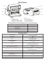 4
4
-
 5
5
-
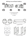 6
6
-
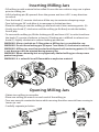 7
7
-
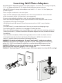 8
8
-
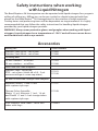 9
9
-
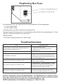 10
10
-
 11
11
-
 12
12
-
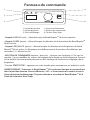 13
13
-
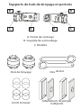 14
14
-
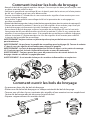 15
15
-
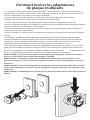 16
16
-
 17
17
-
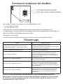 18
18
-
 19
19
-
 20
20
-
 21
21
-
 22
22
-
 23
23
-
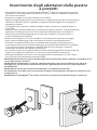 24
24
-
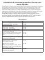 25
25
-
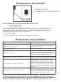 26
26
-
 27
27
-
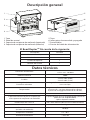 28
28
-
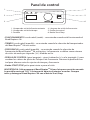 29
29
-
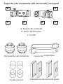 30
30
-
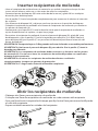 31
31
-
 32
32
-
 33
33
-
 34
34
-
 35
35
-
 36
36
-
 37
37
-
 38
38
-
 39
39
-
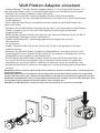 40
40
-
 41
41
-
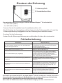 42
42
-
 43
43
-
 44
44


en otros idiomas
- français: Omni Bead Ruptor 96 Manuel utilisateur
- italiano: Omni Bead Ruptor 96 Manuale utente
- English: Omni Bead Ruptor 96 User manual
- Deutsch: Omni Bead Ruptor 96 Benutzerhandbuch
Artículos relacionados

Otros documentos
-
Weston 61-0201-W Guía del usuario
-
 Thermo Fisher Scientific mySPIN 12 Mini Centrifuge Manual de usuario
-
 Thermo Fisher Scientific Multiskan SkyHigh Manual de usuario
-
Tescoma 659560 Instrucciones de operación
-
Bodum 11348 Manual de usuario
-
 Thermo Fisher Scientific Varioskan™ LUX Manual de usuario
-
De'Longhi DFP950 Manual de usuario
-
Aeg-Electrolux CG6600 (WEST) Manual de usuario
-
 JMA DAKAR Manual de usuario
-
Festool 574691 Manual de usuario


