La página se está cargando...

en User Manual
fr Manuel d’utilisation
it Manuale d’uso
es Manual del usuario
de Benutzerhandbuch
GLH 850
General Laboratory Homogenizer
User Manual

en
Data herein has been verified and validated. It is believed adequate for the intended use of the
instrument. If the instrument or procedures are used for purposes over and above the capabilities
specified herein, confirmation of the validity and suitability should be obtained; otherwise Omni
International does not guarantee results and assumes no obligation or liability. This publication is
not a license to operate under, or a recommendation to infringe upon, any process patents.
This product is warranted to be free from defects in material and workmanship for a period of TWO
YEARS from the date of delivery. Omni International will repair or replace and return free of charge
any part which is returned to its factory within said period, transportation prepaid by user, and
which is found upon inspection to have been defective in materials or workmanship. This warranty
does not include normal wear from use; it does not apply to any instrument or parts which have
been altered by anyone other than an employee of Omni International nor to any instrument which
has been damaged through accident, negligence, failure to follow operating instructions, the use
of electric currents or circuits other than those specified on the plate affixed to the instrument,
misuse, or abuse. Omni International reserves the right to change, alter, modify, or improve any of its
instruments without any obligation whatever to make corresponding changes to any instrument
previously sold or shipped.
THE FORGOING OBLIGATION IS IN LIEU OF ALL OBLIGATIONS AND LIABILITIES INCLUDING
NEGLIGENCE AND ALL WARRANTIES OF MERCHANTABILITY OR OTHERWISE, EXPRESSED OR IMPLIED
IN FACT OR BY LAW, AND STATE OUR ENTIRE AND EXCLUSIVE LIABILITY AND BUYERS EXCLUSIVE
REMEDY FOR ANY CLAIM OF DAMAGES IN CONNECTION WITH THE SALE OR FURNISHING OF
GOODS OR PARTS, THEIR DESIGN, SUITABILITY FOR USE, INSTALLATION, OR OPERATION. OMNI
INTERNATIONAL WILL IN NO EVENT BE LIABLE FOR ANY SPECIAL OR CONSEQUENTIAL DAMAGES
WHATSOEVER, AND THEIR LIABILITY UNDER NO CIRCUMSTANCES WILL EXCEED THE CONTRACT
PRICE FOR THE GOODS FOR WHICH LIABILITY IS CLAIMED.
This product has been engineered for safety; however, basic safety precautions and common sense
must always be demonstrated when using any electrical product.
- DO NOT attempt to modify any part of this product.
- DO NOT allow the machine to be submerged in any liquid.
- DO NOT use in any setting other than an indoor laboratory.
- DO NOT plug power cord into an incorrect outlet or subject it to an incorrect voltage.
- Use this product only for its intended purpose.
- DO NOT use attachments not recommended by the manufacturer.
- DO NOT operate the product if it is damaged in any way.
- Keep this product away from heated surfaces.
- DO NOT modify the plug or cord that is provided. If the plug will not fit the outlet, have the proper
outlet installed by a qualified electrician.
- DO NOT operate the product with the safety ground disconnected.
WARNING: Reduce the risk of unintentional starting; make sure the speed switch is in the OFF
position before plugging in the motor.
WARNING: Damaged or worn power cords should be repaired or replaced immediately by a
qualified electrician.
WARNING: Improper connection of the equipment can result in a risk of electric shock.

The Omni GLH 850 Homogenizer consists of the following:
Description Part Number Quantity
Motor Drive Unit (115V) 20-100-00 1
Or Motor Drive Unit (230V) 20-200-00
Power Cord (115V) LT710 1
Or Power Cord (230V) LT708/LT712
Cross Rod/ Plate 50041/50060 1
Clamp FS1002 1
Tool Kit T1001 1
User Manual 03-270 1
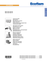
Overview
1
2
3
4
5
6
7
8
9
1. Digital Display
2. Speed Control
3. Timer Control
4. Run Button
5. Stop Button
6. Power Cord Port
7. On/Off Switch
8. Cross Rod Port (stand mounting)
9. Generator Probe Coupling
Cross Rod
Clamp
Optional Stand Available (sold separately) - Part Number S1000

Stand Mounting
1. Assemble the stand (sold separately).
2. Insert the cross rod into the cross rod
port at the back of the unit and tighten
thumb screw by turning clockwise
until tight.
3. Loosen the second knob on the post
clamp and insert the cross rod with
motor attached (approximately 1”
of the cross rod should protrude from
the back of the post clamp).Lock in place.
1”
Stand
Part No. S1000
(sold separately)
Cross Rod
Port
Cross Rod
Thumb Screw
Clamp

*Never run dry
Generator
Coupling
1. Insert Generator
Probe into coupling
2. Quarter turn
clockwise to lock
3. Ready to use
*always submerge probe in
liquid before starting
1/4 Turn
Type Size Quantity Part. No.
Hard Tissue 7 mm x 110 mm 25 Pack 30750H
7 mm x 110 mm 50 Pack 32750H
Adapter (required for plastic probes) 1 A1000SB
Accessories
Generator Probes
Plastic Disposable Generator Probes
Size Processing
Range Type Part. No.
5 mm x 75 mm .02 mL - 5 mL Flat Bottom G5-75
7 mm x 115 mm .25 mL - 30 mL Saw Tooth G7-115ST
Saw Tooth - Wide Window G7-115STW
10 mm x 115 mm 1.5 mL - 100 mL Saw Tooth G10-115
Saw Tooth - Wide Window G10-115W
20 mm x 195 mm 100 mL - 2 L Saw Tooth G20-195ST
Saw Tooth - Wide Window G20-195STW
30 mm x 195 mm 200 mL - 5 L Flat Bottom G-30NA-195
Flat Bottom - Wide Window G-30WA-195
Generator Probes

Operation
General Operation
Power
- Plug in the power cord and move the On/Off switch on back of the unit to the On position.
Set Speed
- Adjust speed using up and down arrow buttons.
Set Timer
- Adjust run time using up and down arrow buttons.
Start
- Press Run button.
Delayed Start
- Press and hold the Run button for 3 seconds .The display will then countdown for 30 seconds
before beginning to run.
Constant Run
- Set the timer above 9:59 or below 0:01. The display will read Constant Run. Press Run to start.
Pause/Stop
- Press Stop Button to Pause.
- Press Stop again to reset timer.
1
2
3
4
5
6
7
8
1. Digital Display
2. Timer
3. Speed Control
4. Timer Control
5. RPM
6. Run Button
7. Stop Button
8. On/Off switch
(back of unit)

Troubleshooting
Error Codes
Error Code Definition Cause Possible Solution
Error 1 Motor is not turning
Motor has overheated
Unplug and let stand
for at least 1 hour at
room temperature, then
attempt to restart.
Something is physically preventing
the motor from turning
Remove generator probe
and attemot to run the
motor.
Check that the generator
probe (removed from the
motor) spins freely
Check for foreign objects
inside the generator
probe port.
Error 2
Motor has failed to reach
the desired speed, or is
drawing too much power
to reach speed desired.
Generator probe is too large
for the speed desired or the
sample is too large/viscous to be
processed.
Reduce desired speed
Reduce the generator
probe size
Reduce the viscosity
of the sample being
processed

fr
Les données dans la présente ont été vérifiées et validées. Nous estimons qu’elles sont adéquates
pour l’utilisation prévue de l’instrument. Si l’instrument ou les procédures sont utilisées à des fins
au-delà et au-dessus des capacités spécifiées dans la présente, la confirmation de la validité et de la
pertinence doit être obtenue ; sinon Omni International ne garantira pas les résultats et n’assumera
aucune obligation ni responsabilité. Cette publication ne constitue pas une licence d’utilisation, ni une
recommandation de violer des brevets de procédés.
Ce produit est garanti exempt de défauts de matériaux et de fabrication pendant une période de
DEUX ANS à compter de la date de livraison. Omni International réparera ou remplacera et retournera
gratuitement toute pièce qui est retournée à son usine pendant ladite période, le transport ayant
été payé par l’utilisateur, et dont les défauts de matériaux et de fabrication ont été constaté par une
inspection. Cette garantie ne couvre pas l’usure normale résultant de l’utilisation du produit ; elle
ne s’applique pas aux instruments ni aux pièces qui ont été modifiés par quiconque autre qu’un
employé de Omni International, ni à tout instrument qui a été endommagé par accident, négligence,
non-respect des consignes d’utilisation, l’utilisation de courants électriques ou de circuits autres que
ceux indiquée sur la plaque apposée sur l’instrument, par une mauvaise utilisation ou un abus. Omni
International se réserve le droit de changer, d’altérer, de modifier ou d’améliorer n’importe lequel de ses
instruments sans aucune obligation que ce soit à apporter des modifications correspondantes à tout
instrument déjà vendu ou expédié.
LA PRÉSENTE OBLIGATION REMPLACE TOUTE AUTRE OBLIGATION ET RESPONSABILITÉ, Y COMPRIS
LA NÉGLIGENCE ET TOUTE AUTRE GARANTIE DE QUALITÉ MARCHANDE OU AUTREMENT, EXPRESSE
OU IMPLICITE EN FAIT OU EN DROIT, ET AFFIRME NOTRE ENTIÈRE ET EXCLUSIVE RESPONSABILITÉ
ET LE RECOURS EXCLUSIF DES ACHETEURS POUR TOUTE DEMANDE DE DOMMAGES DANS LE
CADRE DE LA VENTE OU FOURNITURE DE BIENS OU DE PIÈCES, LEUR CONCEPTION, PERTINENCE
POUR UTILISATION, INSTALLATION OU FONCTIONNEMENT. OMNI INTERNATIONAL NE SERA EN
AUCUN CAS RESPONSABLE DE DOMMAGES PARTICULIERS OU INDIRECTS QUELS QU’ILS SOIENT, ET
SA RESPONSABILITÉ EN AUCUN CAS NE DÉPASSERA LE PRIX PRÉVU DANS LE CONTRAT POUR LES
PRODUITS POUR LESQUELS LA RESPONSABILITÉ EST REVENDIQUÉE.
Ce produit a été mis au point en tenant compte de la sécurité de l’opérateur ; toutefois, toujours
suivre des précautions de sécurité de base et faire preuve de bon sens lors de l’utilisation de produits
électriques.
- NE PAS essayer de modifier des pièces de ce produit.
- NE PAS submerger la machine dans un liquide.
- NE PAS utiliser d’autres milieux qu’un laboratoire intérieur.
- NE PAS brancher le cordon d’alimentation dans une prise inadéquate ni le soumettre à une
tension incorrecte.
- Utiliser ce produit uniquement pour l’usage auquel il est destiné.
- NE PAS utiliser des accessoires non recommandés par le fabricant.
- NE PAS faire fonctionner le produit s’il a subi un dommage d’une manière ou d’une autre.
- Tenir le produit à l’écart de surfaces chauffées.
- NE PAS modifier la fiche ou le cordon fournis. Si la fiche ne correspond pas à la prise, demander à un
électricien qualifié d’installer une prise adéquate.
- NE PAS faire fonctionner le produit avec la mise à la terre débranchée.
AVERTISSEMENT : réduire le risque de démarrage involontaire ; s’assurer que l’interrupteur de vitesse est
sur la position OFF avant de brancher le moteur.
AVERTISSEMENT : les cordons d’alimentation endommagés ou usés doivent être réparés ou remplacés
immédiatement par un électricien qualifié.
AVERTISSEMENT : un branchement inadéquat de l’équipement peut entraîner un risque de choc
électrique.

L’homogénéisateur GLH 850 comprend les éléments suivants :
Description Numéro de commande Quantité
Unité d’entraînement du moteur (115V) 20-100-00
1
ou Unité d’entraînement du moteur (230V) 20-200-00
Cordon d’alimentation (115V) LT710 1
Cordon d’alimentation (230V) LT708/LT712
Barre transversale/ Assiette 50041/50060 1
Étrier de fixation FS1002 1
Trousse d’outils T1001 1
Manuel d’utilisation 03-270 1
Aperçu
1
2
3
4
5
6
7
8
9
1. Affichage numérique
2. Contrôle de la vitesse
3. Contrôle de la minuterie
4. Bouton de fonctionnement
5. Bouton d’arrêt
6. Port du cordon d’alimentation
7. Interrupteur ON/OFF
8. Port de la barre transversale
(montage sur socle)
9. Accouplement de la sonde de générateur
Barre transversale Étrier de fixation
Socle disponible en option (vendu séparément) – numéro de commande. S1000

Montage du socle
1. Assembler le socle (vendu
séparément)
2. Insérer la barre transversale dans
le port destiné à la barre transversale
au dos de l’appareil et serrer la vis de
serrage en la tournant dans le sens des
aiguilles d’une montre.
3. Desserrer la seconde vis à oreilles de
l’étrier de fixation de la tige et insérer
la barre transversale avec le moteur
ataché (environ 1 pouce de la barre
transversale doit saillir du dos de l’étrier
de fixation de la tige). Resserrer pour
verrouiller la vis en place.
1”
Socle
numéro de commande
S1000
(vendu séparément)
Port de
la barre
transversale
Barre transversale
Vis de serrage
Étrier de fixation

Accouplement
du générateur
1. Insérer la sonde
de générateur dans l’accouplement
2. Un quart de tour dans
le sens des aiguilles d’une
montre pour verrouiller
3. Prête à l’emploi
*toujours submerger la sonde
dans un liquide avant de
commencer
¼ de tour
Type Taille Quantité numéro de commande
Tissu dur 7 mm x 110 mm 25 par paquet 15340176
7 mm x 110 mm 50 par paquet 15340177
Tejido suave 7 mm x 110 mm 25 par paquet 30750
7 mm x 110 mm 50 par paquet 32750
Adaptateur
(obligatoire pour les sondes en plastique) 1 15340150
Accessoires
Générateur Jetables
Sondes de générateur jetables en plastique
Taille Plage de traitement Type numéro de commande
5 mm x 75 mm .02 mL - 5 mL Embout plat G5-75
7 mm x 115 mm .25 mL - 30 mL Embout en dents de scie G7-115ST
Embouts en dents de scie – fenêtres de traitement larges G7-115STW
10 mm x 115 mm 1.5 mL - 100 mL Embout en dents de scie G10-115
Embouts en dents de scie – fenêtres de traitement larges G10-115W
20 mm x 195 mm 100 mL - 2 L Embout en dents de scie G20-195ST
Embouts en dents de scie – fenêtres de traitement larges G20-195STW
30 mm x 195 mm 200 mL - 5 L Embout plat G-30NA-195
Embout plat - fenêtres de traitement larges G-30WA-195
Sondes de générateur
*Ne jamais faire fonctionner à sec

Fonctionnement
Fonctionnement Général
Mise sous tension
- Brancher le cordon d’alimentation et déplacer l’interrupteur ON/OFF situé au dos de l’appareil sur la position
ON.
Réglage de la vitesse
- Régler la vitesse à l’aide des boutons haut et bas.
Réglage de la minuterie
- Régler la durée de fonctionnement à l’aide des boutons haut et bas
Démarrage
- Appuyer sur le bouton de fonctionnement
Démarrage diéré
- Appuyer sur le bouton de fonctionnement pendant 3 secondes et le maintenir enfoncé. L’écran fera alors un
compte à rebours pendant 30 secondes avant de commencer à fonctionner.
Fonctionnement continu
- Régler la minuterie au-dessus de 9:59 ou en dessous de 0:01. L’écran affichera
Fonctionnement continu.
- Appuyer sur le bouton de fonctionnement pour démarrer.
Pause/Arrêt
- Appuyer sur le bouton d’arrêt pour interrompre momentanément.
- Appuyer sur le bouton d’arrêt à nouveau pour réinitialiser la minuterie
1
2
3
4
5
6
7
8
1. Affichage numérique
2. Minuterie
3. Contrôle de la vitesse
4. Contrôle de la minuterie
5. T/M
6. Bouton de fonctionnement
7. Bouton d’arrêt
8. Interrupteur ON/OFF
Dos de l’appareil

Dépannage
Codes d’erreur
Code d’erreur Définition Cause Solution possible
Erreur 1 Moteur ne fonctionne pas
Moteur a surchauffé
Le débrancher et le
laisser reposer pendant
au moins 1 heure à
température ambiante
et essayer ensuite de le
redémarrer
Quelque chose de physique
empêche le moteur de tourner
Retirer la sonde de
générateur et essayer
de faire fonctionner le
moteur.
Vérifier si la sonde de
générateur (retirée du
moteur) tourne librement
Vérifier la présence
de corps étrangers à
l’intérieur du port de la
sonde de générateur.
Erreur 2
Le moteur n’est pas
parvenu à atteindre
la vitesse désirée ou
consomme trop de
courant pour atteindre la
vitesse désirée.
La sonde de générateur est trop
grande pour la vitesse désirée
ou l’échantillon est trop grand/
visqueux pour être traité.
Réduire la vitesse désirée
Réduire la taille de la
sonde de générateur
Réduire la viscosité de
l’échantillon en cours de
traitement

it
I dati qui riportati sono stati verificati e validati.
Si ritiene siano adeguati all’utilizzo previsto dello strumento.
Se lo strumento o le procedure vengono utilizzati per scopi che vanno al di là delle capacità qui
specificate, si dovrà ottenere conferma della validità e dell’adeguatezza; in caso contrario, Omni
International non garantirà i risultati e non si assumerà alcun obbligo o responsabilità.
La presente pubblicazione non costituisce licenza a operare per, o raccomandazione a
infrangere brevetti di processo. Il prodotto è garantito come privo di difetti di materiale o
lavorazione per un periodo di DUE ANNI dalla data di consegna. Omni International riparerà
o sostituirà e restituirà, senza alcun costo, tutte le parti che verranno rinviate alla fabbrica entro
tale periodo, con trasporto a carico dell’utente, e che a seguito di ispezione saranno risultate
difettose nei materiali o nella lavorazione. La garanzia non copre la normale usura; non si applica a
strumenti o componenti che siano stati manomessi da chiunque non sia un dipendente di Omni
International, né ad alcuno strumento che sia stato danneggiato in seguito a incidenti, negligenza,
violazione delle istruzioni operative, uso di corrente elettrica o circuiti diversi da quelli indicati sulla
targa affissa sullo strumento stesso, uso improprio o abuso.
Omni International si riserva il diritto di cambiare, alterare, modificare o migliorare i suoi strumenti
senza alcun obbligo di apportare le medesime modifiche ad altri strumenti venduti o spediti
precedentemente.
GLI OBBLIGHI SUINDICATI SOSTITUISCONO TUTTI GLI OBBLIGHI E LE RESPONSABILITÀ, COMPRESA
LA NEGLIGENZA E TUTTE LE GARANZIE DI COMMERCIABILITÀ O ALTRIMENTI ESPRESSE O IMPLICITE
DI FATTO O PER LEGGE, E STABILISCONO LA NOSTRA COMPLETA ED ESCLUSIVA RESPONSABILITÀ,
NONCHÈ LE SOLUZIONI ESCLUSIVE PER GLI ACQUIRENTI IN CASO DI RICHIESTE DI DANNI LEGATE
ALLA VENDITA O ALLA FORNITURA DI BENI O COMPONENTI, ALLA LORO PROGETTAZIONE,
ADEGUATEZZA ALL’USO, INSTALLAZIONE O FUNZIONAMENTO.
IN NESSUN CASO OMNI INTERNATIONAL SARÀ RITENUTA RESPONSABILE DI DANNI PARTICOLARI O
CONSEQUENZIALI DI QUALSIASI NATURA, E LA RESPONSABILITÀ IN NESSUN CASO POTRÀ SUPERARE
IL PREZZO CONTRATTUALE DEI BENI PER I QUALI VIENE INVOCATA LA RESPONSABILITÀ.
Questo prodotto è stato progettato per funzionare in sicurezza; ciononostante, quando si usano
apparecchiature elettriche, è necessario adottare le fondamentali precauzioni di sicurezza e usare il
buon senso.
NON tentare di modificare nessuna parte di questo prodotto.
NON far sì che la macchina venga immersa in liquidi.
NON usare in ambienti diversi dai laboratori al chiuso.
NON collegare il cavo di alimentazione con prese non adatte o con voltaggi non corretti.
Usare questo prodotto solo per lo scopo per cui è stato progettato.
NON usare accessori non raccomandati dal produttore.
NON mettere in funzione il prodotto se è danneggiato.
Tenere lontano il prodotto dalle superfici riscaldate.
NON modificare la spina o il cavo forniti.
Se la spina non entra nella presa, far installare una presa adeguata da un elettricista qualificato.
NON far funzionare il prodotto con messa a terra scollegata.
ATTENZIONE: Ridurre il rischio di accensione involontaria: controllare che il regolatore di velocità sia
in posizione OFF prima di collegare il motore.
ATTENZIONE: I cavi danneggiati e consumati devono essere riparati o sostituiti immediatamente da
un elettricista qualificato.
ATTENZIONE: Un collegamento scorretto dell’apparecchio può causare scosse elettriche.

L’omogeneizzatore GLH 850 è composto da:
Descrizione Numero d’ordine Quantità
Gruppo motore (115V) 20-100-00 1
O Gruppo motore (230V) 20-200-00
Cavo di alimentazione (115V ) LT710 1
Cavo di alimentazione (230V) LT708/LT712
Asta trasversale/ Piatto 50041/50060 1
Morsetto FS1002 1
Kit accessori T1001 1
Manuale d’uso 03-270 1
Panoramica
1
2
3
4
5
6
7
8
9
1. Schermo digitale
2. Controllo velocità
3. Controllo timer
4. Tasto di avvio
5. Tasto di arresto asta trasversale
6. Porta per cavo di alimentazione
7. Interruttore ON/OFF
8. Vano per asta trasversale
(base di supporto)
9. Accoppiamento sonda generatore
Asta trasversale Morsetto
Supporto opzionale disponibile (venduto separatamente) – Numero d’ordine S1000

Supporto
1. Montare il supporto
(venduto separatamente).
2. Inserire l’asta trasversale nell’appos
ita apertura sul retro dell’apparecchio
e stringere la vite avvitando in senso
orario.
3. Svitare la seconda manopola sul
morsetto della barra e inserire l’asta
trasversale con motore collegato
(circa 1” dell’asta trasver sale
dovrebbe sporgere dal lato posteriore
del morsetto sulla barra).
Fissare in posizione.
1”
Foro per
asta trasversale
Asta trasversale
Vite
Morsetto
Supporto
Numero d’ordine S1000
(venduto separatamente)

Accoppiamento
generatore
1. Inserire la sonda
del generatore
nell’accoppiamento.
2. Ruotare per un
quarto di giro
in senso orario per fissare.
3. Pronto per l’utilizzo.
*Prima di iniziare, immergere
sempre la sonda nel liquido.
1/4 di giro
Tipo Dimensioni Quantità Numero d’ordine
Tessuto rigido 7 mm x 110 mm Confezione da 25 15340176
7 mm x 110 mm Confezione da 50 15340177
Tessuti molli 7 mm x 110 mm Confezione da 25 30750
7 mm x 110 mm Confezione da 50 32750
Adattatore
(necessario per sonde in plastica) 1 15340150
Accessori
Sonde Generatore
Sonde generatore usa e getta in plastica
Dimensioni Intervalli
di lavorazione Tipo Numero d’ordine
5 mm x 75 mm .02 mL - 5 mL Fondo piatto G5-75
7 mm x 115 mm .25 mL - 30 mL Denti a seghetto G7-115ST
Denti a seghetto - apertura ampia G7-115STW
10 mm x 115 mm 1.5 mL - 100 mL Denti a seghetto G10-115
Denti a seghetto - apertura ampia G10-115W
20 mm x 195 mm 100 mL - 2 L Denti a seghetto G20-195ST
Denti a seghetto - apertura ampia G20-195STW
30 mm x 195 mm 200 mL - 5 L Fondo piatto G-30NA-195
Fondo piatto - apertura ampia G-30WA-195
Sonde Generatore
*Non fare mai girare a secco

Funzionamento
Funzionamento Generale
Accensione
- Collegare il cavo di alimentazione e spostare l’interruttore ON/OFF sul lato posteriore dell’apparec
chio in posizione ON.
Impostare la velocità
- Regolare la velocità usando i tasti a freccia su/giù.
Impostare il timer
- Regolare il tempo di lavorazione usando i tasti a freccia su/giù.
Avviamento
- Premere il tasto Avvio.
Avviamento Ritardato
- Premere e tenere premuto il tasto “Avvio” per 3 secondi. Lo schermo mostrerà il conto alla rovescia
per 30 secondi prima che parta il processo.
Lavorazione costante
Il display mostra ”Lavorazione costante”. Premere “Avvio” per avviare.
Pausa/Parada
- Premere il tasto di arresto per mettere in pausa.
- Premere Stop di nuovo per reimpostare il timer.
1
2
3
4
5
6
7
8
1. Schermo digitale
2. Timer
3. Controllo velocità
4. Controllo timer
5. Giri/min
6. Tasto di avvio
7. Tasto di arresto
8. Interruttore ON/OFF
(lato posteriore)

Risoluzione dei problemi
Codici di errore
Errore Definizione Causa Possibile soluzione
Errore 1 Il motore non gira.
Il motore è surriscaldato.
Staccare dalla corrente e
lasciare fermo per almeno
un’ora a temperatura
ambiente, quindi tentare
di riavviare
Qualcosa sta fisicamente
impedendo al motore di girare.
Rimuovere la sonda del
generatore e tentare di far
girare il motore.
Controllare che la
sonda del generatore
(staccata dal motore) giri
liberamente.
Controllare l’eventuale
presenza di corpi estranei
nella porta della sonda
del generatore.
Errore 2
Il motore non è riuscito
a raggiungere la
velocità desiderata o
sta richiedendo troppa
potenza per raggiungere
la velocità desiderata.
La sonda del generatore è troppo
grande per la velocità desiderata
o il campione è troppo grande o
viscoso per essere elaborato.
Ridurre la velocità
desiderata
Ridurre le dimensioni
della sonda del
generatore.
Ridurre la viscosità del
campione da elaborare.

es
Los datos del presente documento se han verificado y validado. Se consideran adecuados para la
utilización prevista del instrumento. Si el instrumento o los procedimientos se utilizan para propósitos
más allá y por encima de las capacidades especificadas aquí, deberá obtenerse confirmación de
la validez e idoneidad; de lo contrario, Omni International no garantiza los resultados y no asume
ninguna obligación o responsabilidad. Esta publicación no es una licencia para operar bajo cualquier
patente de proceso, ni una recomendación para infringirlas.
Se garantiza que este producto está libre de defectos en materiales y mano de obra durante un período
de DOS AÑOS desde la fecha de su entrega. Omni International reparará o reemplazará y devolverá sin
cargo cualquier pieza que se devuelva a su fábrica dentro de dicho período, transporte pagado por el
usuario, y que al inspeccionarse se determine que haya tenido un defecto en materiales o en mano de
obra. Esta garantía no cubre el desgaste normal producto del uso; no se aplica a ningún instrumento
o pieza que hayan sido alteradas por cualquier persona que no sea empleado de Omni International,
ni a ningún instrumento que haya sido dañado por accidente, negligencia, incumplimiento de las
instrucciones de operación, el uso de corrientes eléctricas o circuitos distintos de los especificados en
la placa que está fijada en el instrumento, mal uso o maltrato. Omni International se reserva el derecho
de cambiar, alterar, modificar o mejorar cualquiera de sus instrumentos sin compromiso alguno para
hacer los cambios correspondientes a cualquier instrumento vendido o enviado previamente.
LA ANTERIOR OBLIGACIÓN REEMPLAZA TODAS LAS OBLIGACIONES Y RESPONSABILIDADES LEGALES,
INCLUYENDO LA NEGLIGENCIA Y CUALQUIER GARANTÍA DE COMERCIABILIDAD O DE OTRO TIPO,
EXPRESA O IMPLÍCITA DE HECHO O POR DERECHO, Y ESTIPULA NUESTRA RESPONSABILIDAD ENTERA Y
EXCLUSIVA, Y LA REPARACIÓN EXCLUSIVA DEL COMPRADOR EN CASO DE CUALQUIER RECLAMACIÓN
POR DAÑOS Y PERJUICIOS EN RELACIÓN CON LA VENTA O SUMINISTRO DE BIENES O PIEZAS, SU
DISEÑO, LA IDONEIDAD PARA EL USO, LA INSTALACIÓN O LA OPERACIÓN. OMNI INTERNATIONAL
NO SERÁ EN NINGÚN CASO RESPONSABLE POR NINGÚN DAÑO ESPECIAL O CONSECUENTE, Y SU
RESPONSABILIDAD NO SUPERARÁ, BAJO NINGUNA CIRCUNSTANCIA, EL PRECIO DEL CONTRATO POR
LOS BIENES POR CUYA RESPONSABILIDAD SE RECLAMA.
Este producto se ha sido diseñado para ser seguro; sin embargo, siempre deben tenerse las
precauciones básicas de seguridad y sentido común cuando se utilice cualquier aparato eléctrico.
- NO intente modificar ninguna parte de este producto.
- NO permita que la máquina se sumerja en ningún líquido.
- NO lo utilice en ningún entorno que no sea un laboratorio bajo techo.
- NO conecte el cable de alimentación en un enchufe incorrecto ni lo someta a un voltaje incorrecto.
- Utilice este producto solamente para el propósito para el que está destinado.
- NO use accesorios que no estén recomendados por el fabricante.
- NO haga funcionar el producto si está dañado de cualquier manera.
- Mantenga este producto alejado de superficies calientes.
- NO modifique el enchufe o el cable que se suministra. Si la clavija no encaja en el enchufe, haga que
un electricista cualificado instale un enchufe adecuado.
- NO haga funcionar el producto con la tierra de seguridad desconectada.
ADVERTENCIA: Reduzca el riesgo de encendido accidental. Asegúrese de que el interruptor de
velocidad esté en la posición OFF antes de conectar el motor.
ADVERTENCIA: Los cables de alimentación dañados o desgastados deben ser reparados o
reemplazados inmediatamente por un electricista calificado.
ADVERTENCIA: La conexión incorrecta del equipo puede dar como resultado un riesgo de descarga
eléctrica

El Homogeneizador GLH 850 consta de lo siguiente:
Descripción Part No. Cantidad
Unidad de impulsión del motor (115V) 20-100-00 1
O unidad de impulsión del motor (230V) 20-200-00
Cable de corriente (115V) LT710 1
Cable de corriente (230V) LT708/LT712
Barra cruzada/ Plato 50041/50060 1
Abrazadera FS1002 1
Juego de herramientas T1001 1
Manual del usuario 03-270 1
Descripción General
1
2
3
4
5
6
7
8
9
1. Pantalla digital
2. Control de velocidad
3. Control del temporizador
4. Botón de ejecución
5. Botón de parada
6. Puerto del cable de alimentación
7. Interruptor de encendido y apagado
8. Puerto de la barra cruzada (instalación del soporte)
9. Acoplamiento de la punta de prueba del generador
Barra cruzada Abrazadera
Soporte opcional disponible (se vende por separado) - Part No. S1000

Instalación del soporte
1. Ensamble el soporte
(se vende por separado).
2. Inserte la barra cruzada en el puerto corre
spondiente de la parte posterior de la
unidad y apriete el tornillo moleteado
girando en sentido horario hasta que
quede apretado.
3. Afloje la segunda perilla de la abrazadera
del poste e inserte la barra cruzada con el
motor adjunto (aproximadamente 1” (2,5
cm) de la barra cruzada debe sobresalir de
la parte trasera de la abrazadera del poste).
Bloquéelo en su sitio.
1”
Soporte
Part No.
S1000
(se vende por separado)
Puerto
de la
barra
cruzada
Barra cruzada
Tornillo moleteado
Abrazadera

*Nunca lo haga
funcionar en seco
Acoplamiento
del generador
1. Inserte la punta de
prueba del generador
en el acoplamiento
2. Dé un cuarto de giro en sentido
horario para bloquearla
3. Listo para usarse
*siempre sumerja la punta de
prueba en líquido antes de
comenzar
1/4 de vuelta
Tipo Tamaño Cantidad Part No.
Tejido duro 7 mm x 110 mm Paquete de 25 15340176
7 mm x 110 mm Paquete de 50 15340177
Tejido suave 7 mm x 110 mm Paquete de 25 30750
7 mm x 110 mm Paquete de 50 32750
Adaptador (necesario para las
puntas de prueba de plástico 1 15340150
Accesorios
Puntas de prueba del generador
Puntas de prueba de plástico desechables para el generador
Tamaño Rango de procesamiento Tipo Part No.
5 mm x 75 mm .02 mL - 5 mL Fondo plano G5-75
7 mm x 115 mm .25 mL - 30 mL Serrado G7-115ST
Serrado - ventana ancha G7-115STW
10 mm x 115 mm 1.5 mL - 100 mL Serrado G10-115
Serrado - ventana ancha G10-115W
20 mm x 195 mm 100 mL - 2 L Serrado G20-195ST
Serrado - ventana ancha G20-195STW
30 mm x 195 mm 200 mL - 5 L Fondo plano G-30NA-195
Fondo plano - ventana ancha G-30WA-195
Puntas de prueba del generador

Operación
Operación general
Alimentación
- Enchufe el cable de alimentación y mueva el interruptor de encendido y apagado (On/Off) de la
parte posterior de la unidad a la posición de encendido (On).
Ajuste de velocidad
- Ajuste la velocidad con los botones de flechas arriba y abajo.
Ajuste el temporizador
- Ajuste el tiempo de ejecución utilizando los botones de flechas arriba y abajo.
Inicio
- Oprima el botón de ejecución (Run).
Inicio retrasado
- Presione y sostenga así el botón de ejecución (Run) durante 3 segundos. La pantalla hará entonces
una cuenta atrás durante 30 segundos antes de empezar a funcionar.
Ejecución constante
- Programe el temporizador por encima de 9:59 o por debajo de 0:01. La pantalla mostrará Ejecución
constante. Oprima Ejecución (Run) para comenzar.
Pause/Stop
- Oprima el botón de parada (Stop) para pausar.
- Oprima el botón de parada otra vez para restaurar el temporizador.
1
2
3
4
5
6
7
8
1. Pantalla digital
2. Temporizador
3. Control de velocidad
4. Control del temporizador
5. RPM
6. Botón de ejecución
7. Botón de parada
8. Interruptor de
encendido y apagado (parte posterior de la unidad)

Resolución de problemas
Códigos de error
Código de
error Definición Causa Solución posible
Error 1 El motor no gira
El motor se ha sobrecalentado
Desenchúfelo y déjelo
reposar al menos 1 hora
a temperatura ambiente;
luego intente reiniciarlo.
Hay algo impidiendo
físicamente que el motor gire
Retire la punta de prueba
del generador e intente
hacerlo funcionar.
Compruebe que la punta
de prueba del generador
(extraída del motor) gire
libremente
Busque objetos extraños
dentro del puerto de
la punta de prueba del
generador.
Error 2
El motor no ha podido
alcanzar la velocidad
deseada o está
absorbiendo demasiada
energía para alcanzar la
velocidad deseada.
La punta de prueba del
generador es demasiado grande
para la velocidad deseada o la
muestra es demasiado grande o
viscosa como para procesarla.
Reduzca la velocidad
deseada
Reduzca el tamaño de
la punta de prueba del
generador
Reduzca la viscosidad de
la muestra que se está
procesando

de
Die hier enthaltenen Daten wurden überprüft und validiert. Es wird erwartet, dass sie für die
beabsichtigte Verwendung des Instruments ausreichend sind. Wenn das Instrument oder die
Verfahren für Zwecke verwendet werden, die über die hier spezifizierten Fähigkeiten hinausgehen,
sollte eine Bestätigung der Gültigkeit und Eignung eingeholt werden; ansonsten garantiert
Omni International keine Ergebnisse und übernimmt keine Verpflichtung oder Haftung. Diese
Veröffentlichung ist keine Lizenz dafür, unter einem Verfahrenspatent zu arbeiten und auch keine
Empfehlung, ein solches zu verletzen.
Dieses Produkt unterliegt einer Gewährleistung auf Fehlerfreiheit bei Material und Verarbeitung
für die Dauer von zwei Jahren ab dem Zeitpunkt der Lieferung. Omni International repariert
oder ersetzt und retourniert kostenlos jene Teile, die innerhalb dieser Zeit mit vom Benutzer
vorausbezahlten Transportkosten an das Werk zurückgesandt werden, und bei welchen die
Überprüfung bestehende Material- oder Verarbeitungsfehler zeigt. Diese Gewährleistung gilt
nicht für normale Abnutzung durch Gebrauch; sie gilt nicht für Instrumente oder für Teile, die
von jemand anderem als einem Mitarbeiter von Omni International verändert wurden, noch für
Instrumente, die durch einen Unfall, durch Fahrlässigkeit, Nichtbefolgen der Betriebsanleitung,
Verwendung von anderen elektrischen Strömen oder Schaltungen als von jenen, die auf der
am Instrument angebrachten Platte spezifiziert sind, durch Fehlbedienung oder Missbrauch
beschädigt wurden. Omni International behält sich das Recht vor, jedes seiner Instrumente
zu verändern, abzuändern, zu modifizieren oder zu verbessern, ohne jegliche Verpflichtung,
entsprechende Änderungen an vorher verkauften oder ausgelieferten Instrumenten zu machen.
DIE VORSTEHENDE VERPFLICHTUNG GILT ANSTELLE ALLER PFLICHTEN UND VERBINDLICHKEITEN
EINSCHLIESSLICH FAHRLÄSSIGKEIT UND ALLER GEWÄHRLEISTUNGEN DER MARKTFÄHIGKEIT ODER
AUF ANDERE WEISE, EXPLIZIT ODER IMPLIZIT, TATSÄCHLICH ODER GESETZLICH, UND STELLT UNSERE
GESAMTE UND AUSSCHLIESSLICHE HAFTUNG UND DAS AUSSCHLIESSLICHE RECHTSMITTEL DES
KÄUFERS FÜR SCHADENSERSATZANSPRÜCHE IN VERBINDUNG MIT DEM VERKAUF ODER DER
LIEFERUNG VON ARTIKELN ODER TEILEN, DEREN DESIGN, GEBRAUCHSTAUGLICHKEIT, EINBAU
ODER BETRIEB DAR. OMNI INTERNATIONAL HAFTET IN KEINEM FALL FÜR SPEZIELLE SCHÄDEN
ODER FOLGESCHÄDEN UND IHRE HAFTUNG ÜBERSTEIGT AUF KEINEN FALL DEN VERTRAGSPREIS
FÜR DIE WAREN, FÜR WELCHE DIE HAFTUNG IN ANSPRUCH GENOMMEN WIRD.
Dieses Produkt wurde für sichere Verwendung konstruiert; jedoch müssen bei der Verwendung
von elektrischen Produkten immer grundlegende Sicherheitsvorkehrungen beachtet und der
gesunde Menschenverstand eingesetzt werden.
- Versuchen Sie NICHT, einen Teil dieses Produkts zu ändern.
- Tauchen Sie das Gerät NICHT in eine Flüssigkeit ein.
- Verwenden Sie das Gerät NICHT in einem anderen Umfeld als in einem Innenlabor.
- Stecken Sie das Netzkabel NICHT in einer falschen Steckdose oder an eine falsche Spannung an.
- Verwenden Sie dieses Produkt nur für den vorgesehenen Zweck.
- Verwenden Sie KEIN Zubehör, das nicht vom Hersteller empfohlen ist.
- Nehmen Sie das Produkt NICHT in Betrieb, wenn es in irgendeiner Weise beschädigt ist.
- Halten Sie dieses Produkt fern von heißen Oberflächen.
- Verändern Sie NICHT den mitgelieferten Stecker oder das Kabel. Wenn der Stecker nicht in die
Steckdose passt, lassen Sie eine passende Steckdose von einem qualifizierten Elektriker installieren.
- Nehmen Sie das Produkt NICHT in Betrieb, wenn der Schutzleiter nicht angeschlossen ist.
WARNUNG: Verringern Sie das Risiko von unbeabsichtigtem Starten; stellen Sie sicher, dass der
Drehzahlschalter in der AUS-Position ist, bevor sie in den Motor anschließen.
WARNUNG: Beschädigte oder abgenutzte Netzkabel sollten sofort von einem qualifizierten
Elektriker repariert oder ersetzt werden.
WARNUNG: Ein unsachgemäßer Geräteanschluss kann zu einem Stromschlagrisiko führen.

Der GLH 850 Homogenisator besteht aus folgenden Komponenten:
Beschreibung Bestellnummer Menge
Motor-Antriebseinheit (115 V) 20-100-00 1
Oder Motor-Antriebseinheit (230 V) 20-200-00
Netzkabel (115V) LT710 1
Netzkabel (230V) LT708/LT712
Querstrebe/ Teller 50041/50060 1
Klemme FS1002 1
Werkzeugsatz T1001 1
Bedienungsanleitung 03-270 1
Überblick
1
2
3
4
5
6
7
8
9
1. Digitalanzeige
2. Drehzahlsteuerung
3. Timersteuerung
4. Starttaste
5. Stopptaste
6. Netzkabelanschluss
7. Ein-/Aus-Schalter
8.Querstrebenschlitz (Ständerbefestigung)
9. Generatorsonden-Kupplung
Querstrebe Klemme
Optionaler Ständer verfügbar (gesondert verkauft) - Bestellnummer S1000

Ständerbefestigung
1. Zusammenbau des Ständers
(separat verkauft)
2. Setzen Sie die Querstrebe in den
Schlitz für die Querstrebe an der Rück-
seite des Gerätes ein und drehen Sie die
Rändelschraube im Uhrzeigersinn ein,
bis sie fest sitzt.
3. Lösen Sie den zweiten Knopf an der
Ständerklemme und setzen Sie die
Querstrebe mit montiertem Motor
ein (ca. 1” der Querstrebe sollte aus
der Rückseite der Ständerklemme her
aus ragen). Einrasten lassen.
1”
Ständer
Bestellnummer
S1000
(separat verkauft)
Querstreben-
schlitz
Querstrebe
Rändelschraube
Klemme

*Niemals trocken laufen lassen
Generatorkupplung
1. Setzen Sie die
Generatorsonde in
die Kupplung ein
2. Eine Vierteldrehung
im Uhrzeigersinn um
einzurasten
3.Einsatzbereit
*die Sonde vor dem Start immer
in Flüssigkeit eintauchen
1/4 Umdrehung
Typ Größe Menge Bestellnummer
Hartgewebe 7 mm x 110 mm 25 Stück 15340176
7 mm x 110 mm 50 Stück 15340177
Weichgewebe 7 mm x 110 mm 25 Stück 30750
7 mm x 110 mm 50 Stück 32750
Adapter (erforderlich für Kunststoffsonden) 1 15340150
Zubehör
Generatorsonden
Kunststo-Einweg-Generatorsonden
Größe Verarbeitungsbereich Typ Bestellnummer
5 mm x 75 mm .02 mL - 5 mL Flachboden G5-75
7 mm x 115 mm .25 mL - 30 mL Sägezahn G7-115ST
Sägezahn - Breites Fenster G7-115STW
10 mm x 115 mm 1.5 mL - 100 mL Sägezahn G10-115
Sägezahn - Breites Fenster G10-115W
20 mm x 195 mm 100 mL - 2 L Sägezahn G20-195ST
Sägezahn - Breites Fenster G20-195STW
30 mm x 195 mm 200 mL - 5 L Flachboden G-30NA-195
Flachboden - Breite Fenster G-30WA-195
Generatorsonden

Bedienung
Allgemeine Bedienung
Stromversorgung
- Stecken Sie das Netzkabel an und schalten Sie den Ein-/Aus-Schalter auf der Rückseite des Gerätes
in die Stellung “Ein”.
Geschwindigkeit einstellen
- Passen Sie die Drehzahl mit den nach-oben- und nach-unten-Tasten an.
Timer einstellen
- Passen Sie die Sie Laufzeit mit den nach-oben- und nach-unten-Tasten an..
Start
- Drücken Sie die Starttaste.
Verzögerter Start
- Drücken und halten Sie die Starttaste 3 Sekunden lang. Die Anzeige zählt dann 30 Sekunden lang
herunter bevor der Durchlauf beginnt.
Konstanter Durchlauf
- Stellen Sie den Timer auf über 09:59 oder unter 0:01. Das Display zeigt Constant Run (konstanter
Durchlauf) an. Drücken Sie “Run” um zu starten.
Pause/Stopp
- Drücken Sie Stopp-Taste für Pause.
- Drücken Sie Stopp erneut um den Timer zurückzusetzen.
1
2
3
4
5
6
7
8
1. Digitalanzeige
2. Timer
3. Drehzahlsteuerung
4.Timersteuerung
5. U/MIN
6. Starttaste
7. Stopptaste
8. Ein-/Aus-Schalter
Geräte-Rückseite

Fehlerbehebung
Fehlercodes
Fehlercode Definition Ursache Mögliche Lösung
Fehler 1 Motor dreht nicht
Motor ist überhitzt
Ausstecken und
mindestens 1 Stunde bei
Raumtemperatur stehen
lassen, dann Neustart
versuchen.
Etwas verhindert physisch, dass
sich der Motor dreht
Generatorsonde entfernen
und versuchen, den Motor
laufen zu lassen
Prüfen Sie, ob sich die
Generatorsonde (vom
Motor abgebaut) frei dreht
Überprüfen Sie, ob
Fremdkörper im Inneren
des Generatorsonden-
Anschlusses sind.
Fehler 2
Motor hat die gewünschte
Geschwindigkeit nicht
erreicht oder nimmt zu
viel Strom auf, um die
gewünschte Drehzahl zu
erreichen
Die Generatorsonde ist zu groß
für die gewünschte Drehzahl
oder die Probe ist zu groß/
dickflüssig für die Verarbeitung.
Verringern Sie
die gewünschte
Geschwindigkeit
Verringern Sie die Größe
der Generatorsonde
Verringern Sie die
Viskosität der zu
verarbeitenden Probe

PN03270 Rev.C
935 Cobb Place Blvd.
Kennesaw, GA 30144
800.776.4431 • 770.421.0058
www.omni-inc.com
1/32