
2004
MANUALE ISTRUZIONI
INSTRUCTION MANUAL
LIVRET D’INSTRUCTIONS
ANLEITUNGS HEFT
MANUAL DE INSTRUCCIONES
MANUAL DE INSTRUCCIONES
I
GB
F
D
E
P
I
GB
F
D
E
P
2004
MANUALE ISTRUZIONI
INSTRUCTION MANUAL
LIVRET D’INSTRUCTIONS
ANLEITUNGS HEFT
MANUAL DE INSTRUCCIONES
MANUAL DE INSTRUÇÕES
I
GB
F
D
E
P
I
GB
F
D
E
P
Centralina elettronica
Control unit
Armoires de commande
Steuerung
Centralitas
Unidades de comando
900CT-1A
900CT-1AR
900CT-1AS
MADE IN ECC

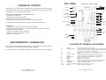
ÍNDICE
2
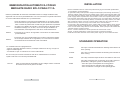
ESTE MANUAL DESTINA-SE EXCLUSIVAMENTE AO INSTALADOR
A instalação deverá ser feita exclusivamente por pessoal profissionalmente
qualificado em conformidade com o previsto pela legislação em vigor
I
P
3
MODELOS E CARACTERÍSTICAS
DADOS TÉCNICOS
QUADRO DE CONJUNTO 900CT-1A 900CT-1AR
LIGAÇÕES NO TERMINAL DE BORNES
LIGAÇÕES FEITAS NA SEDE DE FABRICO-
QUADRO DE CONJUNTO 900CT-1AS
INSTALAÇÃO
FUNCIONAMENTO PADRÃO
AUTO-APRENDIZAGEM DE CÓDIGO CT-1A CT-1AR
OPÇÕES AO FUNCIONAMENTO PADRÃO
AUTO-APRENDIZAGEM DE CÓDIGO VIA RÁDIO, SÓ PARA CT-1A
-
-
-
-
CONTROLO FUNCIONAL
MANUTENÇÃO / ELIMINAÇÃO
ÍNDICE
4
5
6
11
2
-5
-7
-8
-9
-10
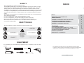
SAFETY
We congratulate you for the excellent choice.
This handbook will help you during the installation of your gear motor. You will
find explanation regarding gear motor's functions and safety rules, which will
always grant you a perfect operating and maximum safety.In order to avoid
damages on your equipment or to injure yourself and other persons, please read
carefully and completely the present handbook before installing the gear motor.
Preserve the instructions, so that everyone can consult them before using the
motor.
We decline all consequences, coming from wrong motor use or non-observance
of the listed precautions.
In case of malfunction, switch off immediately the motor.
In case of reparations, be sure that supply has been turned off.
Don't try to dismount the motor, if your not authorized technician.
Don't expose to fire or heat sources, don't dip in water or other liquids.
Use proper supply cables.
EQUIPMENT
For installation you need following equipment: keys, screwdriver, rule, saw, drill,
welder.
SAFETY RULES
During installation, follow carefully the following saftey rules:
ATTENTION
SAFETY DISTANCE
MAINTAIN PROTECTIVE
CARTER
ELECTRIC SHOCK
USE WELDING
GLASSES
ATTENTION
MOVING GEARS
USE GLOVES
DON’T INSTALL
GEAR MOTOR IN
EXPLOSIVE
MIXTURES
SATURATED
ROOMS

INDEX
2
I
GB
THIS HANDBOOK IS APPOINTED FOR THE INSTALLER ONLY
The installation has to be carried exclusively by qualified personnel
according to the curret law disposal
3
MODELS AND SPECIFICATIONS
TECHNICAL DATA
SET PANEL
TERMINAL BOARD CONNECTIONS
CONNECTIONS MADE IN PRODUCTION
900CT-1A 900CT-1AR
-
SET PANEL 900CT-1AS
I
-
NSTALLATION
-
-
-
STANDARD OPERATION
CT-1A – CT-1AR CODE SELF-LEARNING
CT-1A CODE SELF-LEARNING VIA RADIO
STANDARD OPERATION OPTIONS
TESTING
MAINTENANCE / DISPOSAL
INDEX
4
5
6
11
2
-5
-7
-8
-9
-10
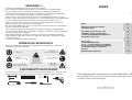
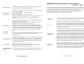
As nossas congratulações pela sua excelente escolha.
Este manual foi preparado para ajudá-lo na instalação do seu motorredutor.
Lendo-o poderá encontrar explicações relativas não apenas às funções do
motorredutor, mas também às normas de segurança que deverá respeitar para
ter sempre um funcionamento perfeito e a máxima segurança.
Para prevenir o risco de provocar danos ao seu equipamento ou lesões a si ou a
terceiros, antes de instalar o motorredutor e os seus componentes, leia integralmente
e com a máxima atenção as advertências que indicamos a seguir e que se
referem às normas de segurança. Conserve-as para que qualquer pessoa que
utilize o aparelho possa consultá-las previamente.
Não nos responsabilizamos pelas consequências decorrentes do não cumprimento
das precauções aqui indicadas.
! Em caso de problemas de funcionamento, desligue o aparelho imediatamente.
! Se tiver de fazer reparações no aparelho, certifique-se primeiro se ele foi desligado
da rede de alimentação eléctrica.
! Não tente desmontar o aparelho, a não ser que seja um instalador autorizado.
! Não exponha o aparelho a chamas ou fontes de calor, não o mergulhe em água
ou noutros líquidos.
! Utilize cabos de alimentação apropriados.
SEGURANÇA
NORMAS DE SEGURANÇA
EQUIPAMENTO NECESSARIO
Durante a instalação e utilização do automatismo, respeite estas normas de
seguranç a com muita atenção:
USAR LUVAS!
CUIDADO
NÃO INSTALAR
O AUTOMATISMO
EM AMBIENTES
SATURADOS COM
MISTURAS EXPLOSIVAS!
CUIDADO
DISTÂNCIA DE SEGURANÇA!
USAR ÓCULOS PARA FAZER
OPERAÇÕES DE SOLDADURA!
MANTER AS COBERTURAS
DE PROTECÇÃO!
CUIDADO
RISCO DE CHOQUE
ELÉCTRICO!
Para instalar o automatismo é necessário dispor do seguinte equipamento: chaves de serviço,
chave de parafuso, fita métrica, bolha de nível, serrote, berbequim, máquina de soldar.
CUIDADO
MECANISMOS EM MOVIMENTO!

MODELS AND SPECIFICATIONS
900CT-1A
900CT-1AR
900CT-1AS
Unit 230V pre-set for electric clutch,with built-in radio
decoder and radio.
Unit 230V pre-set for electric clutch,and for radio card
insertion.
Unit 230V pre-set for electric clutch, and for radio card
insertion.
TECHNICAL DATA
SUPPLY
OUTPUT SUPPLY ACCESSORIES
OPERATING TIME
PAUSE TIME
OPERATING TEMPERATURE
230 VAC/50-HZ
24 VAC/300 MA
2-60 sec
2-180 sec
-20°/+70°
900CT-1A
900CT-1AR
900CT-1AS
3

11
4
PRUEBA DE CONTROL
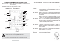
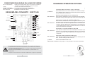
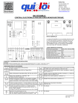
SET PANEL 900CT-1A 900CT-1AR
LIGAÇÕES NO TERMINAL DE BORNES
Rele’
spunto
Rele’
com.
Rele’
ch.
Rele’
ap.
Rele’
lamp.
Fus.
6,3a
Fus.
315ma
Modulo radio
Blocco
Mem.
Memoria
Microprocessore
programmato
p.p.
ch.
ap.
foto
fca
fcc
aut.
Rele’
c.a.
+
+
1
2
34
56789
10
11
12
13
14
17 18
t.pausa
T. TRABALHO
Dip switch
di selezione
P pulsante
autoapprendimento
fcc
Comune finecorsa
fca
Trasf.
secondario
Trasf.
primario
autotrasf.
ap.
co.
ch.
50hz
230 vac
lamp.
300mA
24 Vac
Stop
c.a. Max 2w
foto
ch
ap
pp
ped.
com.
ant.
l
n
(motore)
cort.
lamp.
cond.
1-2
3-4
5-6
6-7
8
9
10
11
12
13
14
15-16
17-18
230Vac 50Mhz mains power supply
Output for flashing unit/courtesy lamp (selection between flashing unit
and courtesy lamp is set on the relative jumper) max 230Vac 25W for
flashing unit, max. 100W for courtesy lamp.
24Vac output for auxiliary power supply (photo, radio etc.) maximum
300mA
Output for door Open indicator lamp 24Vac max 2W
Input for stop command (emergency, external safety lock)
Input for safety devices (photocells, safety edges)
Input for open command
Input for close command
Input for sequential operating mode (open stop close stop)
Input for pedestrian command (see Special Functions)
Common contact for inputs
Output 2° channel (vers.CT-1AS)
Input for radio receiver aerial
230VAC
FLASHING UNIT
24VAC
G.O. IND. LAMP
STOP
PHOTOCELLS
OPEN
CLOSE
STEP
PEDESTRIAN
COMMON
OUTPUT 2 CHANNEL
AERIAL
GB
La prueba de control de toda la instalación en la que está inserta la centralita
deberá realizarla el personal calificado que deberá encargarse de las pruebas
requeridas en función del riesgo presente.
ANTES DE ALIMENTAR LAAUTOMATIZACIÓN
- controlar las conexiones
- poner todos los trimmer al mínimo
- programar los dip switch como se desea
- llevar a posición de fuerza mínima al trimmer de regulación
En cuanto esté todo controlado se puede conectar la alimentación.
ALIMENTAR
- controlar el funcionamiento correcto de las entradas
- regular la fuerza del motor de modo que respete las normativas vigentes
mediante el trimmer prefijado
- controlar el sentido correcto del motor
- regular los trimmer de trabajo y pausa
- realizar un control final
MANTENIMIENTO / ELIMINACIÓN
Por cualquier anomalía de funcionamiento, por reparaciones, mantenimiento o
regulaciones se recomienda buscar personal calificado.
La eliminación de los materiales debe hacerse respetando las normas vigentes.

5
10
Rele’
spunto
Rele’
com.
Rele’
ch.
Rele’
ap.
Rele’
lamp.
Fus.
6,3a
Fus.
315ma
SCHEDA radio
Mem.
Microprocessore
p.p.
ch.
ap.
foto
fca
fcc
aut.
Rele’
c.a.
+
+
1
2
34 56789
10
11
12
13
14
17 18
t.pausa
t.lavoro
Dip switch
di selezione
fcc
com.
fca
Trasf.
secondario
Trasf.
primario
autotrasf.
ap.
co.
ch.
cond.
50hz
230 vac
lamp.
300mA
24 Vac
Stop
c.a. Max 2w
foto
ch
ap
pp
ped.
com.
ant.
15
16
radio
2° ch
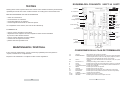
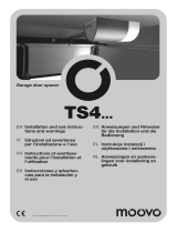
SET PANEL 900CT-1AS
CONNECTIONS MADE IN PRODUCTION
l
N
cort.
lamp.
(MOTORE)
OP-CO-CL (MOTOR)
CAPAC.
PRIMARY TRANSF.
SECONDARY TRANSF.
CLPC-COM-OPPC
Output for motor connection. (If the direction of rotation is incorrect,
invert the connector).
Connection of motor capacitor
Power supply transformer primary
Power supply transformer secondary
Limitswitch input
OPCIONES DEL FUNCIONAMIENTO ESTÁNDAR
JUMPER 1
DIP SWITCH 1
DIP SWITCH 2
DIP SWITCH 3
DIP SWITCH 4
JUMPER
BLOQUEO
MEMORIA
FUNCIÓN INTERMITENTE/CORTESÍA
Mediante esta selección se puede elegir la utilización de una
salida para aprovecharla como intermitente o como luz de
cortesía apagándose 3 minutos después de que el portón ha
completado la maniobra.
FUNCIÓN NORMAL/CONDOMINIAL
Mediante esta selección se puede variar el funcionamiento estándar
del paso/paso (abre stop cierra) convirtiéndose en un mando de
sólo apertura.
FUNCIÓN PAUSA EN APERTURA DE LA CÉLULA FOTOELÉCTRICA
Mediante esta selección se puede lograr el cambio de funcionamiento
estándar de la célula fotoeléctrica. En fase de apertura, al interrumpir
el haz de la célula fotoeléctrica, el portón se detiene. Una vez libre el
haz de la célula fotoeléctrica, el portón continúa con la apertura.
En fase de cierre, si se interrumpe el haz de la célula fotoeléctrica,
el portón se detiene. Una vez libre el haz de la célula foto eléctrica,
el portón invierte la maniobra y se abre.
FUNCIÓN EXCLUSIÓN CIERRE AUTOMÁTICO
Mediante esta selección se puede lograr la exclusión del cierre
automático. El portón, al final de la apertura, no quedará en pausa
el tiempo programado, y quedará detenida en espera de un nuevo
mando de cierre.
FUNCIÓN PROLONGACIÓN DEL TIEMPO DE TRABAJO
Mediante esta selección se puede decidir duplicar el tiempo de
trabajo, regulando de 60 a 120 seg.
SELECCIONA EL BLOQUEO DE MEMORIA
Con Jumper conectado no se pueden realizar
memorizaciones de radiomandos.
E
1
2
3
4
ON
OFF
Carefully read all instructions prior to installation. Failure to observe the above
instructions, improper use or connection errors may impair the safety or correct
operation of the device and consequently the entire system.
The manufacturer declines all liability for malfunctions and/or damage caused
by failure to observe instructions and specifications.
The company reserves the right to apply modifications for product improvements.

9
6
MEMORIZACIÓN AUTOMÁTICA CÓDIGO
MEDIANTE RADIO SÓLO PARA CT-1A
Existe la posibilidad de memorizar automáticamente el código mediante radio,
siguiendo una secuencia preestablecida. Con esta secuencia se puede memorizar
un nuevo radiomando teniendo uno ya memorizado.
CT-1A
FASE 1
FASE 2
Antes de realizar la secuencia preestablecida es necesaria alguna
de las situaciones que permitan entrar en la fase de memorización
radio. Cuando el portón está cerrado hay que presionar el pulsador
de STOP en el tablero de mandos y observando las distintas fases
mediante el testigo C.A. O bien, en el caso de que el tablero no
esté instalado, interrumpiendo el haz de la célula fotoeléctrica.
Presionar por lo menos 10 segundos consecutivos un radiomando
ya memorizado.
Presionar una vez el radiomando que se desea memorizar (dentro
de un tiempo máximo de 10 segundos). Si la secuencia se realiza
correctamente la memorización está concretada.
La centralita sale de la programación:
- apenas superado (durante la fase 2) el tiempo máximo de 10 seg. sin que se
ingrese mando alguno
- al instante en que se memoriza un nuevo radiomando.
En caso de que se desee memorizar más de un radiomando es necesario
repetir cada vez la secuencia preestablecida.
Para la memorización automática de los códigos véase el manual
de instrucciones de las placas de radio
CT1-AS
INSTALLATION
Device installation must be carried out professionally by personnel with qualifications
as specified by current legislation.
To guarantee safety of the operator and prevent damage to parts during connections,
both low voltage (230V) and very low voltage (24V) or when connecting the radio card,
the control unit must always remain disconnected from the power supply. Always keep
power supply cables separate from control cables. In the case of power cables, motor
lines, flashing unit/courtesy lamp lines and electric lock, use cables with a minimum section
of 1,5 mm 2; in the case of auxiliary utilities, commands and safety contacts, use cables
with a minimum section of 0,5 mm 2. When control cables are very long (over 30 m)
disconnection by means of relays in the control unit is recommended.
If a fuse trips, after eliminating the cause, replace with a version with the same characteristics.
Install all safety devices, limit switches, photocells, safety edge, and stop pushbutton.
If one or more of the safety devices are not installed, insert a jumper in the relative terminals
with the controls common contact.
All N.C. contacts related to the same input must be connected in series.
All N.O. contacts related to the same input must be connected in parallel.
Install disconnection elements on the mains power supply in an accessible location.
STANDARD OPERATION
OPEN
CLOSE
STOP
STEP
GB
The open command activates the flashing unit and then starts
door opening.
The close command activates the flashing unit and then starts
door closing.
The stop command stops the door and awaits a new command.
The step command acts on the door via a radio control or
pushbutton, setting the system to different phases:
- from door open it anticipates the closing phase
- from moving door it changes to the stop phase
- from closed door it changes to the opening phase

7
8
PEDESTRIAN
DOOR OPEN
INDICATOR
PHOTOCELL
STARTING
TORQUE
WORKING TIME
PAUSE TIME
FLASHING UNIT
OR COURTESY
LAMP
The pedestrian command starts door opening, which lasts 1/3
of the work time set by means of the trimmer.
The door open indicator lamp notifies the user of the door status.
door closed - lamp off.
door in opening phase - slow flashing lamp.
door open - lamp lit.
door in closing phase - fast flashing lamp.
During the programming phase, it acts as an indicator light, and
at the end of programming returns to its original function
(vers.CT-1A).
The photocell command ensures that on interruption of the light
beam, all controls are inhibited.
During the opening phase, if the beam is interrupted, the door
completes travel to the normal pause position.
During the pause phase, if the beam is interrupted, the door
remains in this status until the beam is restored. When the beam
is restored, the door remains in pause status for a brief interval
(1/4 of the set time) and then closes. During the closing phase,
if the beam is interrupted, the door changes to the opening
phase.
Thrust is activated on opening and closing setting the maximum
force for 1.5 sec. to then return to the set power of the
autotransformer.
Working time range from 2 sec. to 60 sec. (with extension fitted,
the range is extended from 0 sec. to 120 sec.). The adjustment
trimmer to facilitate brief time settings on door movements has
an exponential range (more gradual at the start of the trimmer
range and less at the end).
Pause time range from 2 sec. to 180 sec.
N.B. During opening, if the photocell beam is interrupted, the
pause time is reduced to 1/4 of the set time.
The courtesy lamp uses the same relay as the flashing unit, and
extends operation time if selected for a fixed interval of 3 min.
MEMORIZACIÓN AUTOMÁTICA DEL CÓDIGO
CT-1A CT-1AR
En fase de memorización automática todas las funciones de mando están bloqueadas.
Para entrar en la fase de memorización automática debe existir la condición de portón
cerrado (por lo tanto el testigo C.A. apagado). El led que indica todas las informaciones
de memorización automática está conectado con el testigo C.A.. El testigo C.A.
tendrá en fase de programación, los mismos parpadeos que el led de señalización.
Finalizada la programación retornará a su función original.
ALIMENTACIÓN
CENTRALITA
RESET
MEMORIZACIÓN
AUTOMÁTICA
CÓDIGO
ESTÁNDAR
ANULACIÓN
CÓDIGO
En el momento que se inicia la alimentación de la centralita, el microprocesador
realiza un test interno y el led de señalización emite una serie de 2 parpadeos lentos
y 2 rápidos para indicar que está listo para las fases siguientes.
Cuando se conecta la alimentación y simultáneamente se mantiene presionado
durante 10 seg. el pulsador de memorización automática se puede resetear la
memoria del integrado. Al finalizar esta fase El led de señalización de memorización
automática se encenderá durante 5 seg. con luz constante, para indicar que se
realizó el reset. Al acercarse al final del período de 10 seg. el led de señalización
parpadeará más rápidamente indicando de manera visible que está por completarse
una operación importante delicada.
Presionando durante un instante el pulsador P, el led de señalización emitirá una
serie de parpadeos lentos durante 10 seg. para indicar el inicio de la fase de
memorización automática. En este período, presionando el radio mando se
memoriza automáticamente el código y el canal en el que se ha transmitido
1º, 2º, 2º, 4º del radio mando. Si la memorización fue correcta el led se encenderá
con una luz constante durante 2 seg. El led después de la primera memorización
permanecerá parpadeando los siguientes 6 seg.en espera de una nueva
memorización, si ésta se realiza continuará parpadeando durante los 6 segundos
sucesivos. De lo contrario se sale de la fase de programación. Si en la fase de
memorización se introduce un código ya presente en la memoria, el led emitirá
parpadeos rápidos para indicar que ya se memorizó ese dato. En la fase
memorización automática existe la posibilidad de memorizar más códigos y
también distintos canales (ej.: un primer usuario memoriza el código "x" del
1º canal, un segundo usuario memoriza el código "y" del 2º canal).
Presionando 4 veces distintas el pulsador P. el led emitirá una serie de parpadeos
dobles lentos durante 10 seg. para indicar que se inicia la fase de anulación de
código. En este período,presionando en el radiomando se puede anular el código
de la memoria. A diferencia de la fase de introducción, en la anulación apenas se
ha trasmitido el código se sale automáticamente de la fase de programación. Para
anular otro código se debe repetir la maniobra desde el inicio. Si la anulación fue
correcta el led se encenderá con una luz constante durante 2 seg.
E

7
8
PEATONAL
TESTIGO
PORTÓN
ABIERTO
CÉLULA
FOTOELÉCTRICA
ARRANQUE
TIEMPO DE
TRABAJO
TIEMPO DE
PAUSA
INTERMITENTE
O CORTESÍA
El mando peatonal inicia la apertura del portón que durará 1/3
del tiempo de trabajo programado con el trimmer.
El testigo de portón abierto permite informar al usuario sobre el
estado en que se encuentra el portón.
Portón cerrado testigo apagado.
Portón en fase de apertura testigo con intermitencia lenta.
Portón abierto testigo encendido.
Portón en fase de cierre testigo con intermitencia rápida. En la
fase de programación cumple la función de led de señalización,
retornando al final de la misma a su función original.(vers. CT-1A).
El mando célula fotoeléctrica inhibe todos los mandos cuando se
interrumpe el haz. Si se interrumpe el haz en fase de apertura,
el portón continúa su carrera hasta su posición normal de pausa.
Si se interrumpe el haz en fase de pausa, el portón permanece
en este estado hasta que el haz queda libre de obstáculos. Con
el haz libre se realiza una breve pausa (1/4 del tiempo
programado) y luego el cierre. Si se interrumpe el haz en fase
de cierre, el portón pasa a la fase de apertura.
El arranque interviene en la apertura o en el cierre.
Usando el máximo de la fuerza durante 1,5 seg. para luego volver
a la fuerza prefijada por el transformador automático.
Regulación del tiempo de trabajo de 2 seg. a 60 seg. (con la
prolongación conectada la regulación será de 0 seg. a 120 seg.).
El trimmer de regulación, en tiempos de maniobra breves del
portón y para facilitar la regulación usa una de tipo exponencial
(más gradual al inicio de la carrera del trimmer y menos al final).
Regulación del tiempo de pausa de 2 seg. a 180 seg..
N.B. Si durante la maniobra de apertura el haz de la célula
fotoeléctrica se interrumpe, el tiempo de pausa se reduce a ¼
del programado.
La luz de cortesía aprovecha el mismo relé del intermitente, y
prolonga su funcionamiento si se selecciona por un tiempo fijo
de 3 min.
CT-1A – CT-1AR CODE SELF-LEARNING
In the self-learning phase, all controls are inhibited.
To enter the self-learning phase, the door must be in the closed status (with G.O.
indicator off). The led indicating all self-learning data is connected to the G.O. Indicator.
During programming, the G.O. indicator flashes in the same way as the indicator led,
and then returns to its original function on completion of the programming phase.
CONTROL UNIT
POWER SUPPLY
RESET
STANDARD
CODE
SELF-LEARNING
CODE DELETION
When the control unit is powered up, the microprocessor performs an
internal test and the indicator led emits two slow flashes and two fast
flashes to indicate that it is ready for the next phases.
The integrated memory can be reset on start-up of the control unit by
pressing and holding the self-learning pushbutton for 10 seconds. At the
end of this phase, the self-learning indicator led remains lit for 5 sec. To
indicate successful reset. On approach to the end of the 10 second
interval, the indicator led flashes more quickly to indicate that this important
and delicate operation is about to be completed.
When pushbutton P is pressed briefly, the indicator led emits a series of
slow flashes for 10 sec.
to indicate entry in the self-learning phase. During this interval, if the radio
control is pressed, the code is acquired with the radio control channel on
which it was transmitted (1°, 2°, 3°, or 4°). If the code is memorised
correctly, the led remains lit for 2 sec. After the first memorisation
command, the led flashes for a further 6 sec. on standby for a new
memorisation command; if this is performed, it continues to flash for
6 sec.; otherwise it exits the programming phase. If a previously memorised
code is entered during this phase, the led flashes quickly to indicate that
the code has already been memorised. During the self-learning phase,
there is also the option to memorise several codes also on different
channels (e.g. an initial user memorises the code "x" from channel 1°,
and a second user memorises the code "y" from channel 2°).
Press pushbutton P four times and the led emits a series of slow double
flashes for 10 sec. To indicate entry in the code deletion phase. In this
interval, if the radio control is pressed, the code can be deleted from the
memory. Unlike the entry phase, the unit exits the deletion phase as
soon as the code is transmitted. To delete another code, the same
procedure must be repeated from the start. If deletion is successful, the
led remains lit for 2 sec.
GB

9
6
CT-1A CODE SELF-LEARNING VIA RADIO
The code self-learning process is possible via radio, by following a pre-set sequence.
This sequence enables the memorisation of a new radio control when one is
already memorised.
CT-1A
PHASE 1
PHASE 2
Before following the pre-set sequence, a special condition is required
to specify entry in the radio memorisation mode. With the door closed,
stand in front of the indoor control pushbutton and press the STOP
pushbutton to indicate the various phases by means of the G.O.
indicator.
Otherwise, if the pushbutton panel is not fitted, stand in front of the
photocell beam to interrupt it.
Press for at least 10 consecutive seconds with a radio control already
memorised.
Press once with the radio control to be memorised (with a maximum
extra time interval of 10 seconds). If the sequence is performed
correctly the memorisation phase is complete.
The control unit exits the programming phase:
- when the maximum time interval of 10 seconds elapses (during phase 2) when
no command is given
- when a new radio control has been memorised.
If more than one radio control is to be memorised, the pre-set sequence must be
performed each time.
For self-learning of codes look the instruction
manual of card insertion.
CT1-AS
INSTALACIÓN
La instalación del equipamiento debe realizarse según "reglas de arte" por personal
que cumpla con los requisitos requeridospor las leyes vigentes.
Para garantizar la incolumidad del operador y para prevenir daños a los
componentes, mientras se realizan las conexionesde baja tensión (230V) y de muy
baja tensión (24V) o se acopla la placa de radio, la centralita no debe tener en absoluto
alimentacióneléctrica. Mantener separados los cables de alimentación de los cables de
mando. Para los cablesde alimentación, líneas de motores, línea intermitentes/luz de cortesía,
cerradura eléctrica, utilizar un cable con secciónmínima de 1,5 mm ; para la alimentación
auxiliar, los mandos y los contactos de seguridad deben tener sección mínima de 0,5 mm .
Cuando los cables de mando son muy largos (más de 30 m) es aconsejable un
desacoplamiento mediante relés cercanosa la centralita.
En el caso de la intervención de un fusible, después de haber eliminado la causa, sustituirlo
por otro con las mismas características.
Instalar los distintos dispositivos de seguridad, topes fin de carrera, células fotoeléctricas, borde
sensible, pulsador de stop.Si uno o más dispositivos de seguridad no se instalan, puentear
los bornes respectivos con el de mando común.
Todos los contactos N.C. conectados a una misma entrada deben estar conectados en serie.
Todos los contactos N.A. conectados a una misma entrada deben estar conectados en paralelo.
Prever elementos de desconexión en la red de alimentación en un lugar accesible.
2
2
FUNCIONAMIENTO ESTÁNDAR
ABRE
CIERRA
STOP
PASO/PASO
E
El mando abrir hace que se encienda el intermitente y que luego
se inicie la apertura de la portón.
El mando cerrar hace que se encienda el intermitente y que
luego se inicie el cierre de la portón.
El mando stop detiene el portón y permanece así hasta una
nueva orden.
El mando paso/paso interviene en el portón mediante un
radiomando o pulsador, poniendo al sistema en fases distintas:
- de portón abierto prevé la fase de cierre
-de portón en movimiento pasa a la fase de stop
- de portón cerrado pasa a la fase de apertura

10
STANDARD OPERATION OPTIONS
JUMPER 1
DIP SWITCH 1
DIP SWITCH 2
DIP SWITCH 3
DIP SWITCH 4
JUMPER
MEMORYBLOCK
FLASHING UNIT/COURTESY LAMP FUNCTION
This enables the user to select whether to enable the output
for a flashing unit or that of a courtesy lamp (which turns off 3
minutes after door movement).
NORMAL/APARTMENT BLOCK OPERATION
This selection enables the user to change from the standard
operation of step mode (open stop close) to an open-only command.
PHOTOCELL PAUSE ON OPENING FUNCTION
This selection enables the user to change the standard photocell
operating mode. During the opening phase, if the beam is interrupted
the door stops and when the photocell beam is restored the door
resumes opening. During the closing phase, if the photocell beam
is interrupted the door stops and when the beam is restored the door
inverts movement to open again.
AUTOMATIC CLOSING DISABLE FUNCTION
This selection enables the user to disable the automatic closing
function. On completion of opening the door is not set to pause status
for the set time, but remains stationary on standby for a ne close
command.
WORKING TIME EXTENSION FUNCTION
This selection enables the user to double the working time of the
door from the setting of 60 to 120 sec.
SELECTION MEMORYBLOCK
With insert jumper i is not possible to memorize transmitter
GB
1
2
3
4
ON
OFF
5
RELE’
SPUNTO
RELE’
COM.
RELE’
CH.
RELE’
AP.
RELE’
LAMP.
Fus.
6,3a
Fus.
315ma
SCHEDA radio
Mem.
MICROPROCESADOR
p.p.
ch.
ap.
foto
fca
fcc
aut.
Rele’
c.a.
+
+
1
2
34 56789
10
11
12
13
14
17 18
T.PAUSA
T.TRABAJO
DIP SWITCH
DE SELECCIÓN
FCC
COM.
FCA
TRANSF.
SECUNDARIO
TRANSF.
PRIMARIO
TRANSFORMADOR AUT.
AP.
CO.
CH.
COND.
50HZ
230 VAC
LAMP.
300MA
24 VAC
STOP
C.A. MAX 2W
FOTO
CH
AP
PP
PED.
COM.
ANT.
15
16
RADIO
2° CH
ESQUEMA DEL CONJUNTO 900CT-1AS
CONEXIONES REALIZADAS EN LUGAR DE ORIGEN
L
N
cort.
lamp.
(MOTOR)
AP-CO-CH (MOTOR)
COND.
TRANSF. PRIMARIO
TRANSF. SECUNDARIO
FCC-COM-FCA
Salida para conexión motor. (En el caso de que el sentido de
rotación sea contrario al deseado, invertir el conector).
Conexión del condensador del motor.
Primario del transformador de alimentación.
Secundario del transformador de alimentación.
Entrada de los finales de carrera.
Es conveniente leer atentamente las instrucciones antes de realizar la instalación. El
incumplimiento de las instrucciones mencionadas, el uso inadecuado o conexiones
incorrectas, podría perjudicar la seguridad o el correcto funcionamiento del dispositivo,
y por lo tanto de toda la instalación.
Se declina toda responsabilidad por mal funcionamiento y/o daños debidos a su
incumplimiento.
La empresa se reserva el derecho a introducir modificaciones y mejoras en el producto.

11
4
TESTING
ESQUEMA DEL CONJUNTO 900CT-1A 900CT-1AR
CONEXIONES EN LA CAJA DE TERMINALES
Rele’
spunto
Rele’
com.
Rele’
ch.
Rele’
ap.
Rele’
lamp.
Fus.
6,3a
Fus.
315ma
Modulo radio
Blocco
Mem.
Memoria
Microprocessore
programmato
p.p.
ch.
ap.
foto
fca
fcc
aut.
Rele’
c.a.
+
+
1
2
34
56789
10
11
12
13
14
17 18
t.pausa
T. TRABALHO
Dip switch
di selezione
P pulsante
autoapprendimento
fcc
Comune finecorsa
fca
Trasf.
secondario
Trasf.
primario
autotrasf.
ap.
co.
ch.
50hz
230 vac
lamp.
300mA
24 Vac
Stop
c.a. Max 2w
foto
ch
ap
pp
ped.
com.
ant.
l
n
(motore)
cort.
lamp.
cond.
1-2
3-4
5-6
6-7
8
9
10
11
12
13
14
15-16
17-18
Alimentación de red 230 Vac 50 Mhz.
Salida para intermitente/cortesía (la selección entre intermitente y
cortesía depende de la selección del jumper prefijado) 230Vac
25W máx para intermitente,100 W máx. luz/cortesía.
Salida 24 Vac para alimentación servicios(foto, radio, etc.) Máximo
300 mA.
Salida para testigo portón abierto Vac máx 2W.
Entrada para mando de stop (emergencia, bloqueo o seguridad exterior).
Entrada para dispositivos de seguridad (células fotoeléctricas o
bordes de seguridad).
Entrada para mando de apertura.
Entrada para mando de cierre.
Entrada para funcionamiento cíclico (abre stop cierra stop).
Entrada para mando peatonal (véase Funciones Especiales).
Común para las entradas.
Salida 2º canal (vers.CT-1AS).
Entrada para la antena del receptor de radio.
230VAC
INTERMITENTE
24VAC
TESTIGO C.A.
STOP
CÉLULA
FOTOELÉCTRICA
ABRE
CIERRA
PASO/PASO
PEATONAL
COMÚN
SALIDA 2º CANAL
ANTENA
E
Testing of the entire system where the control unit is installed must be performed by
qualified personnel who must conduct all tests according to the associated risks.
BEFORE POWERING UP THE AUTOMATION
- check all connections
- set all trimmers to minimum
- set all dip switches as required
- set the adjustment trimmer to minimum power
On completion of the above, the unit can be started up.
POWERING UP
- ensure correct operation of all inputs
- adjust the motor output to ensure compliance with current standards
by means of the relative trimmer
- ensure correct direction of motor rotation
- set the work and pause trimmers
- perform the final operation test
MAINTENANCE / DISPOSAL
In the event of malfunctions, ensure exclusively qualified personnel perform
repairs, maintenance or adjustments.
Dispose of all materials in compliance with current regulations.
Transcripción de documentos
Centralina elettronica Control unit Armoires de commande Steuerung Centralitas Unidades de comando 900CT-1A 900CT-1AR 900CT-1AS I MANUALE ISTRUZIONI I MANUALE ISTRUZIONI GB INSTRUCTION MANUAL GB INSTRUCTION MANUAL F LIVRET D’INSTRUCTIONS F LIVRET D’INSTRUCTIONS D ANLEITUNGS HEFT D ANLEITUNGS HEFT E MANUAL DE INSTRUCCIONES E MANUAL DE INSTRUCCIONES P MANUAL DE INSTRUÇÕES P MANUAL DE INSTRUCCIONES MADE IN ECC 2004 ÍNDICE SAFETY We congratulate you for the excellent choice. This handbook will help you during the installation of your gear motor. You will find explanation regarding gear motor's functions and safety rules, which will always grant you a perfect operating and maximum safety.In order to avoid damages on your equipment or to injure yourself and other persons, please read carefully and completely the present handbook before installing the gear motor. Preserve the instructions, so that everyone can consult them before using the motor. We decline all consequences, coming from wrong motor use or non-observance of the listed precautions. In case of malfunction, switch off immediately the motor. In case of reparations, be sure that supply has been turned off. Don't try to dismount the motor, if your not authorized technician. Don't expose to fire or heat sources, don't dip in water or other liquids. Use proper supply cables. SAFETY RULES During installation, follow carefully the following saftey rules: ATTENTION MOVING GEARS USE GLOVES ATTENTION SAFETY DISTANCE USE WELDING GLASSES DON’T INSTALL GEAR MOTOR IN EXPLOSIVE MIXTURES SATURATED ROOMS MAINTAIN PROTECTIVE CARTER IP ÍNDICE 2 MODELOS E CARACTERÍSTICAS DADOS TÉCNICOS 3 QUADRO DE CONJUNTO 900CT-1A 900CT-1AR LIGAÇÕES NO TERMINAL DE BORNES -LIGAÇÕES FEITAS NA SEDE DE FABRICO 4 -5 QUADRO DE CONJUNTO 900CT-1AS 5 INSTALAÇÃO -FUNCIONAMENTO PADRÃO 6 -7 -8 -9 -10 -AUTO-APRENDIZAGEM DE CÓDIGO CT-1A CT-1AR -AUTO-APRENDIZAGEM DE CÓDIGO VIA RÁDIO, SÓ PARA CT-1A -OPÇÕES AO FUNCIONAMENTO PADRÃO CONTROLO FUNCIONAL MANUTENÇÃO / ELIMINAÇÃO 11 ELECTRIC SHOCK EQUIPMENT For installation you need following equipment: keys, screwdriver, rule, saw, drill, welder. ESTE MANUAL DESTINA-SE EXCLUSIVAMENTE AO INSTALADOR A instalação deverá ser feita exclusivamente por pessoal profissionalmente qualificado em conformidade com o previsto pela legislação em vigor 2 SEGURANÇA As nossas congratulações pela sua excelente escolha. Este manual foi preparado para ajudá-lo na instalação do seu motorredutor. Lendo-o poderá encontrar explicações relativas não apenas às funções do motorredutor, mas também às normas de segurança que deverá respeitar para ter sempre um funcionamento perfeito e a máxima segurança. Para prevenir o risco de provocar danos ao seu equipamento ou lesões a si ou a terceiros, antes de instalar o motorredutor e os seus componentes, leia integralmente e com a máxima atenção as advertências que indicamos a seguir e que se referem às normas de segurança. Conserve-as para que qualquer pessoa que utilize o aparelho possa consultá-las previamente. Não nos responsabilizamos pelas consequências decorrentes do não cumprimento das precauções aqui indicadas. ! Em caso de problemas de funcionamento, desligue o aparelho imediatamente. ! Se tiver de fazer reparações no aparelho, certifique-se primeiro se ele foi desligado da rede de alimentação eléctrica. ! Não tente desmontar o aparelho, a não ser que seja um instalador autorizado. ! Não exponha o aparelho a chamas ou fontes de calor, não o mergulhe em água ou noutros líquidos. ! Utilize cabos de alimentação apropriados. NORMAS DE SEGURANÇA Durante a instalação e utilização do automatismo, respeite estas normas de seguranç a com muita atenção: CUIDADO USAR LUVAS! CUIDADO DISTÂNCIA DE SEGURANÇA! USAR ÓCULOS PARA FAZER OPERAÇÕES DE SOLDADURA! INDEX GB I INDEX 2 MODELS AND SPECIFICATIONS TECHNICAL DATA 3 SET PANEL 900CT-1A 900CT-1AR TERMINAL BOARD CONNECTIONS -CONNECTIONS MADE IN PRODUCTION 4 -5 SET PANEL 900CT-1AS 5 INSTALLATION -STANDARD OPERATION -CT-1A – CT-1AR CODE SELF-LEARNING -CT-1A CODE SELF-LEARNING VIA RADIO -STANDARD OPERATION OPTIONS TESTING MAINTENANCE / DISPOSAL 6 -7 -8 -9 -10 11 MECANISMOS EM MOVIMENTO! CUIDADO NÃO INSTALAR O AUTOMATISMO EM AMBIENTES SATURADOS COM MISTURAS EXPLOSIVAS! MANTER AS COBERTURAS DE PROTECÇÃO! CUIDADO RISCO DE CHOQUE ELÉCTRICO! EQUIPAMENTO NECESSARIO Para instalar o automatismo é necessário dispor do seguinte equipamento: chaves de serviço, chave de parafuso, fita métrica, bolha de nível, serrote, berbequim, máquina de soldar. THIS HANDBOOK IS APPOINTED FOR THE INSTALLER ONLY The installation has to be carried exclusively by qualified personnel according to the curret law disposal 2 MODELS AND SPECIFICATIONS 900CT-1A Unit 230V pre-set for electric clutch,with built-in radio decoder and radio. 900CT-1AR Unit 230V pre-set for electric clutch,and for radio card insertion. 900CT-1AS Unit 230V pre-set for electric clutch, and for radio card insertion. TECHNICAL DATA 900CT-1A 900CT-1AR 900CT-1AS SUPPLY 230 VAC/50-HZ OUTPUT SUPPLY ACCESSORIES 24 VAC/300 MA OPERATING TIME 2-60 sec PAUSE TIME 2-180 sec OPERATING TEMPERATURE -20°/+70° 3 SET PANEL PRUEBA DE CONTROL Blocco Mem. lamp. Rele’ c.a. 5 6 7 8 9 10 11 12 13 14 Rele’ ap. Rele’ lamp. 2 3 4 p.p. Memoria P pulsante autoapprendimento fcc Comune finecorsa fca Fus. 315ma ch. ap. foto fca fcc aut. cort. Dip switch di selezione 1 Rele’ com. Rele’ ch. Trasf. secondario autotrasf. Trasf. primario aaaaaaaaaaaaaaaaaaaaa aaaaaaaaaaaaaaaaaaaaa aaaaaaaaaaaaaaaaaaaaa aaaaaaaaaaaaaaaaaaaaa aaaaaaaaaaaaaaaaaaaaa aaaaaaaaaaaaaaaaaaaaa aaaaaaaaaaaaaaaaaaaaa aaaaaaaaaaaaaaaaaaaaa ant. GB com. ped. pp ch ap foto Stop c.a. Max 2w 24 Vac 300mA lamp. n l 230 vac 50hz Fus. 6,3a ap. ch. co. cond. (motore) MANTENIMIENTO / ELIMINACIÓN LIGAÇÕES NO TERMINAL DE BORNES 1-2 3-4 La eliminación de los materiales debe hacerse respetando las normas vigentes. 5-6 6-7 8 9 10 11 12 13 14 15-16 17-18 11 + Microprocessore programmato T. TRABALHO ALIMENTAR - controlar el funcionamiento correcto de las entradas - regular la fuerza del motor de modo que respete las normativas vigentes mediante el trimmer prefijado - controlar el sentido correcto del motor - regular los trimmer de trabajo y pausa - realizar un control final Por cualquier anomalía de funcionamiento, por reparaciones, mantenimiento o regulaciones se recomienda buscar personal calificado. Modulo radio Rele’ spunto En cuanto esté todo controlado se puede conectar la alimentación. 17 18 + t.pausa La prueba de control de toda la instalación en la que está inserta la centralita deberá realizarla el personal calificado que deberá encargarse de las pruebas requeridas en función del riesgo presente. ANTES DE ALIMENTAR LA AUTOMATIZACIÓN - controlar las conexiones - poner todos los trimmer al mínimo - programar los dip switch como se desea - llevar a posición de fuerza mínima al trimmer de regulación 900CT-1A 900CT-1AR 230VAC FLASHING UNIT 230Vac 50Mhz mains power supply Output for flashing unit/courtesy lamp (selection between flashing unit and courtesy lamp is set on the relative jumper) max 230Vac 25W for flashing unit, max. 100W for courtesy lamp. 24VAC 24Vac output for auxiliary power supply (photo, radio etc.) maximum 300mA G.O. IND. LAMP Output for door Open indicator lamp 24Vac max 2W STOP Input for stop command (emergency, external safety lock) PHOTOCELLS Input for safety devices (photocells, safety edges) OPEN Input for open command CLOSE Input for close command STEP Input for sequential operating mode (open stop close stop) PEDESTRIAN Input for pedestrian command (see Special Functions) COMMON Common contact for inputs OUTPUT 2 CHANNELOutput 2° channel (vers.CT-1AS) AERIAL Input for radio receiver aerial 4 CONNECTIONS MADE IN PRODUCTION OP-CO-CL (MOTOR) Output for motor connection. (If the direction of rotation is incorrect, invert the connector). CAPAC. Connection of motor capacitor PRIMARY TRANSF. Power supply transformer primary SECONDARY TRANSF. Power supply transformer secondary CLPC-COM-OPPC Limitswitch input SET PANEL 900CT-1AS + lamp. Rele’ c.a. 5 6 7 8 9 10 11 12 13 14 15 16 17 18 Rele’ lamp. 2 3 4 N 1 l + t.lavoro Mem. p.p. Dip switch di selezione ch. ap. fca fcc aut. cort. Fus. 315ma foto Microprocessore fcc com. fca Rele’ ch. Rele’ spunto Rele’ com. Trasf. secondario autotrasf. Trasf. primario E JUMPER 1 Rele’ ap. SCHEDA radio t.pausa OPCIONES DEL FUNCIONAMIENTO ESTÁNDAR aaaaaaaaaaaaaaaaaaaaa aaaaaaaaaaaaaaaaaaaaa aaaaaaaaaaaaaaaaaaaaa aaaaaaaaaaaaaaaaaaaaa aaaaaaaaaaaaaaaaaaaaa aaaaaaaaaaaaaaaaaaaaa aaaaaaaaaaaaaaaaaaaaa aaaaaaaaaaaaaaaaaaaaa FUNCIÓN INTERMITENTE/CORTESÍA Mediante esta selección se puede elegir la utilización de una salida para aprovecharla como intermitente o como luz de cortesía apagándose 3 minutos después de que el portón ha completado la maniobra. ant. 2° ch radio com. ped. pp ch ap foto Stop c.a. Max 2w DIP SWITCH 1 DIP SWITCH 2 24 Vac 300mA Fus. 6,3a ch. co. cond. (MOTORE) FUNCIÓN PAUSA EN APERTURA DE LA CÉLULA FOTOELÉCTRICA Mediante esta selección se puede lograr el cambio de funcionamiento estándar de la célula fotoeléctrica. En fase de apertura, al interrumpir el haz de la célula fotoeléctrica, el portón se detiene. Una vez libre el haz de la célula fotoeléctrica, el portón continúa con la apertura. En fase de cierre, si se interrumpe el haz de la célula fotoeléctrica, el portón se detiene. Una vez libre el haz de la célula foto eléctrica, el portón invierte la maniobra y se abre. DIP SWITCH 3 FUNCIÓN EXCLUSIÓN CIERRE AUTOMÁTICO Mediante esta selección se puede lograr la exclusión del cierre automático. El portón, al final de la apertura, no quedará en pausa el tiempo programado, y quedará detenida en espera de un nuevo mando de cierre. DIP SWITCH 4 FUNCIÓN PROLONGACIÓN DEL TIEMPO DE TRABAJO Mediante esta selección se puede decidir duplicar el tiempo de trabajo, regulando de 60 a 120 seg. JUMPER BLOQUEO MEMORIA SELECCIONA EL BLOQUEO DE MEMORIA Con Jumper conectado no se pueden realizar memorizaciones de radiomandos. lamp. 230 vac 50hz FUNCIÓN NORMAL/CONDOMINIAL Mediante esta selección se puede variar el funcionamiento estándar del paso/paso (abre stop cierra) convirtiéndose en un mando de sólo apertura. ap. Carefully read all instructions prior to installation. Failure to observe the above instructions, improper use or connection errors may impair the safety or correct operation of the device and consequently the entire system. The manufacturer declines all liability for malfunctions and/or damage caused by failure to observe instructions and specifications. F OF The company reserves the right to apply modifications for product improvements. 5 ON 1 10 23 4 MEMORIZACIÓN AUTOMÁTICA CÓDIGO MEDIANTE RADIO SÓLO PARA CT-1A INSTALLATION Device installation must be carried out professionally by personnel with qualifications as specified by current legislation. To guarantee safety of the operator and prevent damage to parts during connections, both low voltage (230V) and very low voltage (24V) or when connecting the radio card, the control unit must always remain disconnected from the power supply. Always keep power supply cables separate from control cables. In the case of power cables, motor lines, flashing unit/courtesy lamp lines and electric lock, use cables with a minimum section of 1,5 mm 2; in the case of auxiliary utilities, commands and safety contacts, use cables with a minimum section of 0,5 mm 2. When control cables are very long (over 30 m) disconnection by means of relays in the control unit is recommended. If a fuse trips, after eliminating the cause, replace with a version with the same characteristics. Install all safety devices, limit switches, photocells, safety edge, and stop pushbutton. If one or more of the safety devices are not installed, insert a jumper in the relative terminals with the controls common contact. All N.C. contacts related to the same input must be connected in series. All N.O. contacts related to the same input must be connected in parallel. Install disconnection elements on the mains power supply in an accessible location. GB Existe la posibilidad de memorizar automáticamente el código mediante radio, siguiendo una secuencia preestablecida. Con esta secuencia se puede memorizar un nuevo radiomando teniendo uno ya memorizado. CT-1A Antes de realizar la secuencia preestablecida es necesaria alguna de las situaciones que permitan entrar en la fase de memorización radio. Cuando el portón está cerrado hay que presionar el pulsador de STOP en el tablero de mandos y observando las distintas fases mediante el testigo C.A. O bien, en el caso de que el tablero no esté instalado, interrumpiendo el haz de la célula fotoeléctrica. FASE 1 Presionar por lo menos 10 segundos consecutivos un radiomando ya memorizado. FASE 2 Presionar una vez el radiomando que se desea memorizar (dentro de un tiempo máximo de 10 segundos). Si la secuencia se realiza correctamente la memorización está concretada. La centralita sale de la programación: - apenas superado (durante la fase 2) el tiempo máximo de 10 seg. sin que se ingrese mando alguno - al instante en que se memoriza un nuevo radiomando. En caso de que se desee memorizar más de un radiomando es necesario repetir cada vez la secuencia preestablecida. CT1-AS Para la memorización automática de los códigos véase el manual de instrucciones de las placas de radio 9 STANDARD OPERATION OPEN The open command activates the flashing unit and then starts door opening. CLOSE The close command activates the flashing unit and then starts door closing. STOP The stop command stops the door and awaits a new command. STEP The step command acts on the door via a radio control or pushbutton, setting the system to different phases: - from door open it anticipates the closing phase - from moving door it changes to the stop phase - from closed door it changes to the opening phase 6 MEMORIZACIÓN AUTOMÁTICA DEL CÓDIGO CT-1A CT-1AR PEDESTRIAN The pedestrian command starts door opening, which lasts 1/3 of the work time set by means of the trimmer. DOOR OPEN INDICATOR The door open indicator lamp notifies the user of the door status. door closed - lamp off. door in opening phase - slow flashing lamp. door open - lamp lit. door in closing phase - fast flashing lamp. During the programming phase, it acts as an indicator light, and at the end of programming returns to its original function (vers.CT-1A). PHOTOCELL STARTING TORQUE The photocell command ensures that on interruption of the light beam, all controls are inhibited. During the opening phase, if the beam is interrupted, the door completes travel to the normal pause position. During the pause phase, if the beam is interrupted, the door remains in this status until the beam is restored. When the beam is restored, the door remains in pause status for a brief interval (1/4 of the set time) and then closes. During the closing phase, if the beam is interrupted, the door changes to the opening phase. Thrust is activated on opening and closing setting the maximum force for 1.5 sec. to then return to the set power of the autotransformer. WORKING TIME Working time range from 2 sec. to 60 sec. (with extension fitted, the range is extended from 0 sec. to 120 sec.). The adjustment trimmer to facilitate brief time settings on door movements has an exponential range (more gradual at the start of the trimmer range and less at the end). PAUSE TIME Pause time range from 2 sec. to 180 sec. N.B. During opening, if the photocell beam is interrupted, the pause time is reduced to 1/4 of the set time. FLASHING UNIT OR COURTESY LAMP The courtesy lamp uses the same relay as the flashing unit, and extends operation time if selected for a fixed interval of 3 min. 7 En fase de memorización automática todas las funciones de mando están bloqueadas. Para entrar en la fase de memorización automática debe existir la condición de portón cerrado (por lo tanto el testigo C.A. apagado). El led que indica todas las informaciones de memorización automática está conectado con el testigo C.A.. El testigo C.A. tendrá en fase de programación, los mismos parpadeos que el led de señalización. Finalizada la programación retornará a su función original. E ALIMENTACIÓN CENTRALITA En el momento que se inicia la alimentación de la centralita, el microprocesador realiza un test interno y el led de señalización emite una serie de 2 parpadeos lentos y 2 rápidos para indicar que está listo para las fases siguientes. RESET Cuando se conecta la alimentación y simultáneamente se mantiene presionado durante 10 seg. el pulsador de memorización automática se puede resetear la memoria del integrado. Al finalizar esta fase El led de señalización de memorización automática se encenderá durante 5 seg. con luz constante, para indicar que se realizó el reset. Al acercarse al final del período de 10 seg. el led de señalización parpadeará más rápidamente indicando de manera visible que está por completarse una operación importante delicada. MEMORIZACIÓN AUTOMÁTICA CÓDIGO ESTÁNDAR ANULACIÓN CÓDIGO Presionando durante un instante el pulsador P, el led de señalización emitirá una serie de parpadeos lentos durante 10 seg. para indicar el inicio de la fase de memorización automática. En este período, presionando el radio mando se memoriza automáticamente el código y el canal en el que se ha transmitido 1º, 2º, 2º, 4º del radio mando. Si la memorización fue correcta el led se encenderá con una luz constante durante 2 seg. El led después de la primera memorización permanecerá parpadeando los siguientes 6 seg.en espera de una nueva memorización, si ésta se realiza continuará parpadeando durante los 6 segundos sucesivos. De lo contrario se sale de la fase de programación. Si en la fase de memorización se introduce un código ya presente en la memoria, el led emitirá parpadeos rápidos para indicar que ya se memorizó ese dato. En la fase memorización automática existe la posibilidad de memorizar más códigos y también distintos canales (ej.: un primer usuario memoriza el código "x" del 1º canal, un segundo usuario memoriza el código "y" del 2º canal). Presionando 4 veces distintas el pulsador P. el led emitirá una serie de parpadeos dobles lentos durante 10 seg. para indicar que se inicia la fase de anulación de código. En este período,presionando en el radiomando se puede anular el código de la memoria. A diferencia de la fase de introducción, en la anulación apenas se ha trasmitido el código se sale automáticamente de la fase de programación. Para anular otro código se debe repetir la maniobra desde el inicio. Si la anulación fue correcta el led se encenderá con una luz constante durante 2 seg. 8 CT-1A – CT-1AR CODE SELF-LEARNING PEATONAL El mando peatonal inicia la apertura del portón que durará 1/3 del tiempo de trabajo programado con el trimmer. TESTIGO PORTÓN ABIERTO El testigo de portón abierto permite informar al usuario sobre el estado en que se encuentra el portón. Portón cerrado testigo apagado. Portón en fase de apertura testigo con intermitencia lenta. Portón abierto testigo encendido. Portón en fase de cierre testigo con intermitencia rápida. En la fase de programación cumple la función de led de señalización, retornando al final de la misma a su función original.(vers. CT-1A). El mando célula fotoeléctrica inhibe todos los mandos cuando se interrumpe el haz. Si se interrumpe el haz en fase de apertura, el portón continúa su carrera hasta su posición normal de pausa. CÉLULA Si se interrumpe el haz en fase de pausa, el portón permanece FOTOELÉCTRICA en este estado hasta que el haz queda libre de obstáculos. Con el haz libre se realiza una breve pausa (1/4 del tiempo programado) y luego el cierre. Si se interrumpe el haz en fase de cierre, el portón pasa a la fase de apertura. ARRANQUE El arranque interviene en la apertura o en el cierre. Usando el máximo de la fuerza durante 1,5 seg. para luego volver a la fuerza prefijada por el transformador automático. TIEMPO DE TRABAJO Regulación del tiempo de trabajo de 2 seg. a 60 seg. (con la prolongación conectada la regulación será de 0 seg. a 120 seg.). El trimmer de regulación, en tiempos de maniobra breves del portón y para facilitar la regulación usa una de tipo exponencial (más gradual al inicio de la carrera del trimmer y menos al final). TIEMPO DE PAUSA Regulación del tiempo de pausa de 2 seg. a 180 seg.. N.B. Si durante la maniobra de apertura el haz de la célula fotoeléctrica se interrumpe, el tiempo de pausa se reduce a ¼ del programado. INTERMITENTE O CORTESÍA La luz de cortesía aprovecha el mismo relé del intermitente, y prolonga su funcionamiento si se selecciona por un tiempo fijo de 3 min. 7 In the self-learning phase, all controls are inhibited. To enter the self-learning phase, the door must be in the closed status (with G.O. indicator off). The led indicating all self-learning data is connected to the G.O. Indicator. During programming, the G.O. indicator flashes in the same way as the indicator led, and then returns to its original function on completion of the programming phase. CONTROL UNIT POWER SUPPLY RESET STANDARD CODE SELF-LEARNING CODE DELETION GB When the control unit is powered up, the microprocessor performs an internal test and the indicator led emits two slow flashes and two fast flashes to indicate that it is ready for the next phases. The integrated memory can be reset on start-up of the control unit by pressing and holding the self-learning pushbutton for 10 seconds. At the end of this phase, the self-learning indicator led remains lit for 5 sec. To indicate successful reset. On approach to the end of the 10 second interval, the indicator led flashes more quickly to indicate that this important and delicate operation is about to be completed. When pushbutton P is pressed briefly, the indicator led emits a series of slow flashes for 10 sec. to indicate entry in the self-learning phase. During this interval, if the radio control is pressed, the code is acquired with the radio control channel on which it was transmitted (1°, 2°, 3°, or 4°). If the code is memorised correctly, the led remains lit for 2 sec. After the first memorisation command, the led flashes for a further 6 sec. on standby for a new memorisation command; if this is performed, it continues to flash for 6 sec.; otherwise it exits the programming phase. If a previously memorised code is entered during this phase, the led flashes quickly to indicate that the code has already been memorised. During the self-learning phase, there is also the option to memorise several codes also on different channels (e.g. an initial user memorises the code "x" from channel 1°, and a second user memorises the code "y" from channel 2°). Press pushbutton P four times and the led emits a series of slow double flashes for 10 sec. To indicate entry in the code deletion phase. In this interval, if the radio control is pressed, the code can be deleted from the memory. Unlike the entry phase, the unit exits the deletion phase as soon as the code is transmitted. To delete another code, the same procedure must be repeated from the start. If deletion is successful, the led remains lit for 2 sec. 8 INSTALACIÓN CT-1A CODE SELF-LEARNING VIA RADIO La instalación del equipamiento debe realizarse según "reglas de arte" por personal que cumpla con los requisitos requeridos por las leyes vigentes. Para garantizar la incolumidad del operador y para prevenir daños a los componentes, mientras se realizan las conexiones de baja tensión (230V) y de muy baja tensión (24V) o se acopla la placa de radio, la centralita no debe tener en absoluto alimentacióneléctrica. Mantener separados los cables de alimentación de los cables de mando. Para los cables de alimentación, líneas de motores, línea intermitentes/luz de cortesía, 2 cerradura eléctrica, utilizar un cable con sección mínima de 1,5 mm ; para la alimentación 2 auxiliar, los mandos y los contactos de seguridad deben tener sección mínima de 0,5 mm . Cuando los cables de mando son muy largos (más de 30 m) es aconsejable un desacoplamiento mediante relés cercanos a la centralita. En el caso de la intervención de un fusible, después de haber eliminado la causa, sustituirlo por otro con las mismas características. Instalar los distintos dispositivos de seguridad, topes fin de carrera, células fotoeléctricas, borde sensible, pulsador de stop. Si uno o más dispositivos de seguridad no se instalan, puentear los bornes respectivos con el de mando común. Todos los contactos N.C. conectados a una misma entrada deben estar conectados en serie. Todos los contactos N.A. conectados a una misma entrada deben estar conectados en paralelo. Prever elementos de desconexión en la red de alimentación en un lugar accesible. E The code self-learning process is possible via radio, by following a pre-set sequence. This sequence enables the memorisation of a new radio control when one is already memorised. CT-1A PHASE 1 PHASE 2 Before following the pre-set sequence, a special condition is required to specify entry in the radio memorisation mode. With the door closed, stand in front of the indoor control pushbutton and press the STOP pushbutton to indicate the various phases by means of the G.O. indicator. Otherwise, if the pushbutton panel is not fitted, stand in front of the photocell beam to interrupt it. Press for at least 10 consecutive seconds with a radio control already memorised. Press once with the radio control to be memorised (with a maximum extra time interval of 10 seconds). If the sequence is performed correctly the memorisation phase is complete. The control unit exits the programming phase: - when the maximum time interval of 10 seconds elapses (during phase 2) when no command is given - when a new radio control has been memorised. If more than one radio control is to be memorised, the pre-set sequence must be performed each time. CT1-AS For self-learning of codes look the instruction manual of card insertion. 9 FUNCIONAMIENTO ESTÁNDAR ABRE El mando abrir hace que se encienda el intermitente y que luego se inicie la apertura de la portón. CIERRA El mando cerrar hace que se encienda el intermitente y que luego se inicie el cierre de la portón. STOP El mando stop detiene el portón y permanece así hasta una nueva orden. PASO/PASO El mando paso/paso interviene en el portón mediante un radiomando o pulsador, poniendo al sistema en fases distintas: - de portón abierto prevé la fase de cierre -de portón en movimiento pasa a la fase de stop - de portón cerrado pasa a la fase de apertura 6 CONEXIONES REALIZADAS EN LUGAR DE ORIGEN STANDARD OPERATION OPTIONS AP-CO-CH (MOTOR) Salida para conexión motor. (En el caso de que el sentido de rotación sea contrario al deseado, invertir el conector). COND. Conexión del condensador del motor. TRANSF. PRIMARIO Primario del transformador de alimentación. TRANSF. SECUNDARIO Secundario del transformador de alimentación. FCC-COM-FCA Entrada de los finales de carrera. + SCHEDA radio T.PAUSA + T.TRABAJO Mem. Rele’ c.a. 5 6 7 8 9 10 11 12 13 14 15 16 17 18 ESQUEMA DEL CONJUNTO 900CT-1AS p.p. ch. DIP SWITCH DE SELECCIÓN ap. DIP SWITCH 1 NORMAL/APARTMENT BLOCK OPERATION This selection enables the user to change from the standard operation of step mode (open stop close) to an open-only command. DIP SWITCH 2 PHOTOCELL PAUSE ON OPENING FUNCTION This selection enables the user to change the standard photocell operating mode. During the opening phase, if the beam is interrupted the door stops and when the photocell beam is restored the door resumes opening. During the closing phase, if the photocell beam is interrupted the door stops and when the beam is restored the door inverts movement to open again. DIP SWITCH 3 AUTOMATIC CLOSING DISABLE FUNCTION This selection enables the user to disable the automatic closing function. On completion of opening the door is not set to pause status for the set time, but remains stationary on standby for a ne close command. DIP SWITCH 4 WORKING TIME EXTENSION FUNCTION This selection enables the user to double the working time of the door from the setting of 60 to 120 sec. N 1 24 VAC 300MA L LAMP. 230 VAC 50HZ TRANSFORMADOR AUT. TRANSF. PRIMARIO JUMPER 1 FLASHING UNIT/COURTESY LAMP FUNCTION This enables the user to select whether to enable the output for a flashing unit or that of a courtesy lamp (which turns off 3 minutes after door movement). ANT. 2° CH RADIO COM. PED. PP CH AP FOTO STOP C.A. MAX 2W RELE’ LAMP. 2 3 4 cort. RELE’ CH. RELE’ SPUNTO RELE’ COM. TRANSF. SECUNDARIO RELE’ AP. lamp. Fus. 315ma MICROPROCESADOR FCC COM. FCA foto fca fcc aut. aaaaaaaaaaaaaaaaaaaaa aaaaaaaaaaaaaaaaaaaaa aaaaaaaaaaaaaaaaaaaaa aaaaaaaaaaaaaaaaaaaaa aaaaaaaaaaaaaaaaaaaaa aaaaaaaaaaaaaaaaaaaaa aaaaaaaaaaaaaaaaaaaaa aaaaaaaaaaaaaaaaaaaaa GB Fus. 6,3a JUMPER SELECTION MEMORYBLOCK MEMORYBLOCK With insert jumper i is not possible to memorize transmitter AP. CH. CO. COND. (MOTOR) Es conveniente leer atentamente las instrucciones antes de realizar la instalación. El incumplimiento de las instrucciones mencionadas, el uso inadecuado o conexiones incorrectas, podría perjudicar la seguridad o el correcto funcionamiento del dispositivo, y por lo tanto de toda la instalación. Se declina toda responsabilidad por mal funcionamiento y/o daños debidos a su incumplimiento. ON F OF La empresa se reserva el derecho a introducir modificaciones y mejoras en el producto. 5 1 10 23 4 ESQUEMA DEL CONJUNTO 900CT-1A 900CT-1AR TESTING fcc Comune finecorsa fca Fus. 315ma ap. foto fca fcc aut. 1 autotrasf. Trasf. primario ant. E com. ped. pp ch ap foto Stop c.a. Max 2w 24 Vac 300mA lamp. n l 230 vac 50hz Fus. 6,3a CONEXIONES EN LA CAJA DE TERMINALES 1-2 3-4 Dispose of all materials in compliance with current regulations. 5-6 6-7 8 9 10 11 12 13 14 15-16 17-18 11 aaaaaaaaaaaaaaaaaaaaa aaaaaaaaaaaaaaaaaaaaa aaaaaaaaaaaaaaaaaaaaa aaaaaaaaaaaaaaaaaaaaa aaaaaaaaaaaaaaaaaaaaa aaaaaaaaaaaaaaaaaaaaa aaaaaaaaaaaaaaaaaaaaa aaaaaaaaaaaaaaaaaaaaa ap. ch. co. cond. (motore) MAINTENANCE / DISPOSAL In the event of malfunctions, ensure exclusively qualified personnel perform repairs, maintenance or adjustments. Rele’ ch. Rele’ com. - ensure correct operation of all inputs - adjust the motor output to ensure compliance with current standards by means of the relative trimmer - ensure correct direction of motor rotation - set the work and pause trimmers - perform the final operation test Rele’ spunto Trasf. secondario POWERING UP Rele’ c.a. 5 6 7 8 9 10 11 12 13 14 On completion of the above, the unit can be started up. Rele’ lamp. 2 3 4 P pulsante autoapprendimento ch. cort. - check all connections - set all trimmers to minimum - set all dip switches as required - set the adjustment trimmer to minimum power p.p. lamp. Dip switch di selezione Blocco Mem. Rele’ ap. BEFORE POWERING UP THE AUTOMATION + Memoria T. TRABALHO Modulo radio Microprocessore programmato Testing of the entire system where the control unit is installed must be performed by qualified personnel who must conduct all tests according to the associated risks. 17 18 + t.pausa 230VAC INTERMITENTE Alimentación de red 230 Vac 50 Mhz. Salida para intermitente/cortesía (la selección entre intermitente y cortesía depende de la selección del jumper prefijado) 230Vac 25W máx para intermitente,100 W máx. luz/cortesía. 24VAC Salida 24 Vac para alimentación servicios(foto, radio, etc.) Máximo 300 mA. TESTIGO C.A. Salida para testigo portón abierto Vac máx 2W. STOP Entrada para mando de stop (emergencia, bloqueo o seguridad exterior). CÉLULA Entrada para dispositivos de seguridad (células fotoeléctricas o FOTOELÉCTRICA bordes de seguridad). ABRE Entrada para mando de apertura. CIERRA Entrada para mando de cierre. PASO/PASO Entrada para funcionamiento cíclico (abre stop cierra stop). PEATONAL Entrada para mando peatonal (véase Funciones Especiales). COMÚN Común para las entradas. SALIDA 2º CANAL Salida 2º canal (vers.CT-1AS). ANTENA Entrada para la antena del receptor de radio. 4-
 1
1
-
 2
2
-
 3
3
-
 4
4
-
 5
5
-
 6
6
-
 7
7
-
 8
8
-
 9
9
-
 10
10
-
 11
11
-
 12
12


Key Automation 900CT-1A Manual de usuario
- Tipo
- Manual de usuario
en otros idiomas
- English: Key Automation 900CT-1A User manual
Artículos relacionados

Otros documentos
-
Key Gates 900CT-2 Guía del usuario
-
 quiko QK-CE220RLX Manual de usuario
-
Nice Automation ROBO24 El manual del propietario
-
-
Telcoma Zen El manual del propietario
-
 Moovo TS4 El manual del propietario
-
Genius SPRINT11SW Instrucciones de operación
-
-
 GiBiDi PASS 800 Instructions For Installation Manual
-
FAAC D600 Manual de usuario


