
S40
CABINA AUDIOMÉTRICA
AUDIOMETRIC TEST BOOTH
MANUAL DEL USUARIO
USER’S MANUAL
501-700-MUM · Rev. 2.01 · 2018-04
EN
ES

Manual de Uso Cabina S40
501-700-MUM · Rev 2.01
Manual Cabina Audiométrica S40
Revisión: 501-700-MUM Rev 2.01
Todos los derechos reservados.
SIBEL S.A.U.
Rosellón 500 bajos, 08026 BARCELONA (Spain)
Ventas Nacionales: Tel. 93 436 00 08 e-mail: [email protected]
International Sales:Tel. +34 93 436 00 07 e-mail: [email protected]
Servicio técnico: Tel. +34 93 433 54 50 e-mail: [email protected]
Fax: +34 93 436 16 11, www.sibelmed.com
AVISO SOBRE EL COPYRIGHT
Ninguna parte de esta publicación podrá ser reproducida, transmitida,
transcrita, almacenada en un sistema back-up ni traducida a ningún idioma
o lenguaje informático en ninguna forma o por ningún medio, electrónico,
mecánico, óptico, químico, manual o de cualquier otro tipo, sin el expreso
consentimiento escrito por parte de SIBEL S.A.U.
DESCARGO DE RESPONSABILIDADES
SIBEL S.A.U. se responsabiliza de la seguridad, abilidad y funcionamiento
de este producto sólo si:
• El local donde se instale o se utilice el producto cumple con los requisitos
relativos a la instalación eléctrica IEC, así como las demás normativas que le
sean de aplicación.
• Las reparaciones, revisiones o modicaciones, tanto dentro como fuera del
período de garantía, son efectuadas por personal técnico de SIBEL S.A.U.
• El producto es utilizado por personal cualicado y de acuerdo con las
recomendaciones de este Manual de Uso.
ES 1

Manual de Uso Cabina S40
501-700-MUM · Rev 2.01
ES 2
PRODUCTO CONFORME A LA DIRECTIVA DE
PRODUCTOS SANITARIOS
93/42/CEE (CLASE I).
Revisado Aprobado
Fecha: 2018-04 Fecha: 2018-04
Director Técnico Director Comercial

Manual de Uso Cabina S40
501-700-MUM · Rev 2.01
ES 3
ÍNDICE
1. INSTRUCCIONES DE UTILIZACIÓN E INSTALACIÓN ................... 4
1.1. INTRODUCCIÓN .......................................................................... 4
1.2. OBSERVACIONES PREVIAS ........................................................... 4
1.3. VISIÓN GENERAL DE LA CABINA .................................................7
1.4. INSTALACIÓN Y PUESTA EN SERVICIO ...........................................8
1.4.1. INSTALACIÓN ..........................................................................8
1.4.2. PUESTA EN SERVICIO ...............................................................8
2. ESPECIFICACIONES TÉCNICAS ................................................... 9
3. PRINCIPIOS DE FUNCIONAMIENTO ......................................... 12
4. ENTRETENIMIENTO, MANTENIMIENTO PREVENTIVO Y
CORRECTIVO ................................................................................ 12
4.1. ENTRETENIMIENTO ................................................................... 12
4.2. MANTENIMIENTO PREVENTIVO ................................................... 13
4.2.1. SUPERVISIÓN ........................................................................ 13
4.2.2. REVISIÓN DE LAS INTERCONEXIONES ...................................... 13
4.3. MANTENIMIENTO CORRECTIVO ................................................... 13

Manual de Uso Cabina S40
501-700-MUM · Rev 2.01
ES 4
1. INSTRUCCIONES DE UTILIZACIÓN E INSTALACIÓN
1.1. INTRODUCCIÓN
Las cabinas insonorizadas SIBELMED S40 han sido diseñadas por el
departamento de I+D+i de SIBEL S.A.U., utilizando los más novedosos
materiales en aislamiento acústico.
La cabina insonorizada SIBELMED S40 es una cámara individual que atenúa las
ondas sonoras entre su exterior y su interior. Esta característica de atenuación
sonora permite realizar pruebas de audiometría en las condiciones de ruido
ambiental que especican las normas referentes a como se deben realizar este
tipo de medidas. (Para mayor información consultar las normas ANSI S3.1 e
ISO 8253-1).
La cabina dispone de una puerta de acceso con cierre, de una ventana que
permite la mutua visualización entre paciente y operador, de iluminación
agradable y de las conexiones necesarias para conectar un audiómetro con
todos sus accesorios.
1.2. OBSERVACIONES PREVIAS
Esta cabina ha sido fabricada siguiendo unos estrictos controles de calidad. Sin
embargo, pueden suceder accidentes en el transporte o en el almacenamiento
de las cabinas, por lo que es conveniente hacer una revisión inicial de su
estado antes de instalarla, así como de los accesorios que la complementan.
ADVERTENCIA
SI DETECTA ALGÚN DETERIORO EN EL EMBALAJE, CONTACTE
INMEDIATAMENTE CON LA AGENCIA DE TRANSPORTE Y CON SU
DISTRIBUIDOR ANTES DE PROCEDER A INSTALARLA. NO SE DEBE
DESPRENDER DE LOS EMBALAJES, BOLSAS, ETC., HASTA QUE
VERIFIQUE TOTALMENTE EL CORRECTO FUNCIONAMIENTO DEL
EQUIPO.
ADVERTENCIA
NO ALMACENAR LA CABINA SIN MONTAR. EL HACERLO PUEDE
PROVOCAR LA DEFORMACIÓN DE LOS PANELES, CON LO QUE EL
PRODUCTO NO QUEDARÍA CUBIERTO POR LA GARANTÍA.

Manual de Uso Cabina S40
501-700-MUM · Rev 2.01
ES 5
ELIMINACIÓN DE RESIDUOS DE APARATOS ELÉCTRICOS Y
ELECTRÓNICOS POR PARTE DE USUARIOS DOMÉSTICOS EN LA UNIÓN
EUROPEA
Este símbolo en el producto indica que no se puede desechar la parte
eléctrica de este producto junto con los residuos domésticos.
Por el contrario, si debe eliminar este tipo de residuo, es responsabilidad
del usuario desmontar el panel y la parte eléctrica de la cabina y entregarlo
en un punto de recolección designado de reciclado de aparatos electrónicos
y eléctricos. El reciclaje y la recolección por separado de estos residuos en
el momento de la eliminación, ayudará a preservar recursos naturales y a
garantizar que el reciclaje proteja la salud y el medio ambiente.
Si desea información adicional sobre los lugares donde puede dejar estos
residuos para su reciclado, póngase en contacto con las autoridades locales
de su ciudad, con el servicio de gestión de residuos domésticos o con el
distribuidor donde adquirió el producto.
La cabina insonorizada S40 está compuesta de las siguientes unidades y
accesorios:
Código Cant. Descripción
---- 1 CABINA SIBELMED S40 Modelo A,B,C,D,E o F
01217 1 CABLE DE RED CON CLAVIJA EUROPEA*
501-700-MU_ 1 MANUAL DE USO
501-708-GR_ 1 GUÍA DE MONTAJE
02214 5 INTERCONEXION AUDIOMETRO-CABINA (6.3 mm)
---- 1 INTERCONEXIÓN AUDIOMETRO-CABINA (3.5 mm)
09079, 09117 1 PANEL CON 8 CONEXIONES (OPC.)
(Sólo modelos B, C, E, F)
02789 1 CONGUNTO RUEDAS MODELOS A, D (OPC.)
08898 1 CONGUNTO RUEDAS MODELOS B, C, E (OPC.)
03658 1 CABLE USB TIPO A-B 2.0
* Consultar para otras opciones
Estos códigos pueden usarse para solicitar repuestos de las citadas opciones
o accesorios.

Manual de Uso Cabina S40
501-700-MUM · Rev 2.01
ES 6
La serie de Cabinas Insonorizadas S40 está formada por los siguientes
modelos:
S40-A (90x90x213 cm.)
S40-B (110x110x213 cm)
S40-C (127x127x213 cm)
S40-D (86x73x187 cm.) (Unidades móviles)
S40-E (133 x 133 x 213 cm)
S40-F (Proyectos a medida)

Manual de Uso Cabina S40
501-700-MUM · Rev 2.01
ES 7
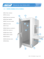
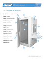
1.3. VISIÓN GENERAL DE LA CABINA
Nº 1: Panel ventana
Nº 2: Ventana
Nº 3: Placa de conexiones
Nº 4: Mesa abatible
Nº 5: Cierre de la mesa
Nº6: Cantoneras
Nº 7: Techo
Nº 8: Rejilla de ventilación
Nº 9: Panel posterior
Nº 10: Panel lateral
Nº 11: Marco puerta
Nº 12: Puerta
Nº 13: Manilla puerta
Nº 14: Base
1
2
3
4
5
6
7
8
10
9
13
14
12
11

Manual de Uso Cabina S40
501-700-MUM · Rev 2.01
ES 8
1.4. INSTALACIÓN Y PUESTA EN SERVICIO
1.4.1. INSTALACIÓN
Para proceder al montaje de la cabina, se deben seguir los siguientes pasos:
Elija el lugar donde se va a situar la cabina y su disposición. Es decir, dónde
se va a situar el panel frontal, que incluye la ventana, y la mesa, y a qué lado
del panel frontal se va a colocar la puerta, así como su sentido de apertura.
Nota: Dispuesta la colocación del panel frontal, el panel posterior debe ir en
el lado opuesto, y dispuesta la colocación de la puerta, el panel lateral debe ir
en el lado opuesto.
Consulte la guía de montaje (501-708-GR_) que se entrega con la cabina
para su correcta instalación.
1.4.2. PUESTA EN SERVICIO
Para la puesta en servicio de la cabina se deben seguir los pasos descritos a
continuación:
NOTA: Se presupone que el usuario dispone de un audiómetro para conectar
en la cabina.
• Conecte el cable de red a la base de entrada de red de la cabina y
posteriormente conéctelo a la red.
• Compruebe que accionando el interruptor general (Nº3) se ilumina el interior
de la cabina. (En caso de que no se iluminase compruebe el paso anterior y su
red de alimentación). Déjelo apagado.
• Sitúe el audiómetro sobre la bandeja y conecte el cable de red de éste a la
base de salida de red (Nº3). NOTA IMPORTANTE: Máxima carga 500 W.
• Conecte los accesorios del audiómetro en las conexiones internas de la
cabina y cuélguelos en los soportes que para ello están dispuestos.
• Recuerde el número de la conexión de cada accesorio para a continuación
realizar la conexión del audiómetro a los conectores exteriores de la cabina
(Nº3), con el propósito de que cada accesorio quede conectado correctamente
al audiómetro.

Manual de Uso Cabina S40
501-700-MUM · Rev 2.01
ES 9
ADVERTENCIA
SI DURANTE EL PROCESO DE INSTALACIÓN O EN CUALQUIER OTRO
INSTANTE SE LE PRESENTARA ALGUNA DUDA, CONTACTE CON EL
SERVICIO POSTVENTA DE SIBEL S.A.U. O CON SU DISTRIBUIDOR.
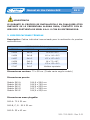
2. ESPECIFICACIONES TÉCNICAS
Descripción: Cabina individual insonorizada para la realización de pruebas
audiométricas.
MEDIDAS GAMA S40 (cm.)
CÓDIGO MODELOS EXTERIORES
01634 S40-A 90 x 90 x 213
01636 S40-B 110 x 110 x 213
01637 S40-C 127 x 127 x 213
01639 S40-D 86 x 73 x 187
01640 S40-E 133 x 133 x 213
07107 S40-F Medidas especiales
Dimensiones ventana: 70 x 58 cm. (Puede variar según modelo)
Dimensiones puerta:
Modelo S40-A 184,8 x 58,8 cm.
Modelo S40-B 184,8 x 78,8 cm.
Modelo S40-C 184,8 x 95,8 cm.
Modelo S40-D 162,7 x 58,8 cm.
Modelo S40-E 184,8 x 95,8 cm.
Dimensiones mesa plegable:
S40-A: 70 X 50 cm.
S40-B, C, E: 90 X 50 cm.
S40-D: 55 x 43 cm.

Manual de Uso Cabina S40
501-700-MUM · Rev 2.01
ES 10
Alimentación: 220 V - 50/60 Hz. (Otros voltajes opcionales).
Circuito eléctrico de paso de red con interruptor y señalizador luminoso.
Iluminación interna por lámpara de Leds
Consumo eléctrico interno: inferior a 40 W.
Potencia máxima de carga: 500 W.
Conexiones de paso de la cabina: 5 conexiones tipo jack hembra de 6.3 mm
Stereo y 1 conexión tipo jack hembra de 3.5 mm destinadas a la conexión de
los accesorios del audiómetro.
Vida útil del producto: 10 años
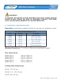
Atenuación global para ruido blanco de banda entre 250 y 8000 Hz: 36 dB.
Atenuación máxima para ruido blanco: 49,7 dB a 5000 Hz
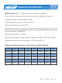
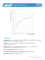
Índice de aislamiento Dp por frecuencias (modelo S40–B):
f (Hz) 100 125 160 200 250 315 400
Dp (dB) 10,5 24,8 28,5 29,5 29,8 28,7 30,5
f (Hz) 500 630 800 1000 1250 1600 2000
Dp (dB) 32,4 34,2 36,1 37,9 37,1 39,1 39,8
f (Hz) 2500 3150 4000 5000 6300 8000 10000
Dp (dB) 43,3 45,9 47,5 49,7 44,1 45,0 45,6

Manual de Uso Cabina S40
501-700-MUM · Rev 2.01
ES 11
NORMAS
Audiometría: Permite el cumplimiento de las normas ISO 8253-1 y ANSI
S3.1 dependiendo las condiciones del entorno.
Calidad: Sistema de Calidad de Sibel (EN ISO 9001:2008 y EN ISO
13485:2012+AC:2012)
Seguridad: EN 60601-1:2006+AC:2010+A1:2013+AC:2014, EN 60601-1-
6:2010+A1:2015, EN 62366:2008+A1:2015
Gestión de Riesgos: EN ISO 14971:2012
Información Suministrada por el fabricante: EN 1041:2008
Símbolos utilizados: EN-ISO 15223-1:2016

Manual de Uso Cabina S40
501-700-MUM · Rev 2.01
ES 12
3. PRINCIPIOS DE FUNCIONAMIENTO
Según las normativas de audiometría ANSI S3.1 e ISO 8253-1 las pruebas
audiométricas deben realizarse en unas condiciones que el ruido ambiental no
enmascare los resultados de dichas pruebas.
Para ello, la cabina es un recinto aislado acústicamente en cuyo interior el
ruido de fondo es muy inferior al ruido del exterior, permitiendo la realización
correcta de las pruebas audiométricas.
La cabina dispone de unos paneles que contienen diferentes capas de material
atenuador del sonido. El principio básico que produce la atenuación del sonido
es conocido como la ley de la masa. Otras consideraciones a tener en cuenta
para disponer de una buena atenuación sonora se basan en la combinación
adecuada de los materiales, así como sus dimensiones, todo ello para evitar
efectos indeseados tales como el efecto de coincidencia. (Para más informa-
ción se pueden consultar tratados sobre Acústica e insonorización).
4. ENTRETENIMIENTO, MANTENIMIENTO PREVENTIVO Y CORRECTIVO
La cabina insonora S40 requiere como cualquier equipo un entretenimiento
y mantenimiento encaminados a garantizar la abilidad y la exactitud de las
funciones para las que ha sido desarrollada. Todo esto comporta una serie de
rutinas que se deben ejecutar.
4.1. ENTRETENIMIENTO
El entretenimiento es la acción encaminada a mantener el equipo en situa-
ción de correcto funcionamiento y la persona que lo lleva a cabo no requiere
ninguna cualidad técnica especial a excepción del conocimiento propio de las
funciones y manipulación del equipo. Normalmente debe realizarlo el mismo
usuario del equipo. Las operaciones a realizar son las siguientes:
La supercie exterior de la cabina se puede limpiar con agua y jabón, secando
posteriormente los restos de humedad que queden. En el interior de la cabina,
las paredes de espuma y el suelo enmoquetado se pueden limpiar con un as-
pirador convencional; las partes de plástico y la ventana se pueden lavar con
agua y jabón.
No utilizar sustancias abrasivas o disolventes que puedan atacar el acabado
de la cabina.

Manual de Uso Cabina S40
501-700-MUM · Rev 2.01
ES 13
4.2. MANTENIMIENTO PREVENTIVO
El mantenimiento preventivo consiste en todas aquellas acciones encamina-
das a sostener el equipo en buen estado de uso.
4.2.1. SUPERVISIÓN
El usuario puede efectuar periódicamente una supervisión del aspecto de la
cabina, la iluminación interna, el cierre de la puerta y el estado de las inter-
conexiones. En ella se vericará que ningún elemento presente rotura o daño
externo.
4.2.2. REVISIÓN DE LAS INTERCONEXIONES
Semestralmente se puede comprobar con la ayuda de un audiómetro que las
interconexiones funcionan correctamente y no producen ruidos que pudieran
reducir la abilidad de las pruebas audiométricas.
4.3. MANTENIMIENTO CORRECTIVO
El mantenimiento correctivo consiste en dejar el equipo en buen estado de uso
que por mal funcionamiento o mal uso haya dejado de prestar servicio y sea
necesario reparar.
En caso de detectar una avería en el equipo que impida su utilización normal,
contacte con el servicio postventa de Sibel, S.A.U., especicando con el mayor
detalle posible el tipo de anomalía que se ha producido.

S40 User’s manual
501-700-MUM · Rev 2.01
EN 1
Audiometric test booth S40
Revision: 501-700-MUM Rev 2.01
All rights reserved
This manual can be purchased through the After Sales Service.
SIBEL S.A.U.
Rosellón 500 bajos, 08026 BARCELONA (Spain)
National Sales: Tel. +34 93 436 00 08 e-mail: [email protected]
International Sales:Tel. +34 93 436 00 07 e-mail: [email protected]
Technical Service: Tel. +34 93 433 54 50 e-mail: [email protected]
Fax: +34 93 436 16 11, Web: www.sibelmed.com
ADVICE ABOUT THE COPYRIGHT
No part of this publication may be reproduced, transmitted, transcribed, stored
in a back-up system or translated into any language or computer language
in any form or by any means, electronic, mechanical, optical, chemical or
manual without the express written consent from SIBEL S.A.U.
DISCLAIMER
SIBEL S.A.U. is responsible for the security, reliability and performance of
this product only if:
• The place where the system is installed meets the requirments of electric
installation IEC and other applicable regulations.
• Repairs, revisions or modications, within and outside the warranty period
are carried out by technical personnel of SIBEL S.A.U.
• The product is used by qualied staff in accordance with the recommendations
of this User’s Manual

S40 User’s manual
501-700-MUM · Rev 2.01
EN 2
PRODUCT IN COMPLIANCE WITH MEDICAL
DEVICE DIRECTIVE
93/42/EEC (CLASS I).
Revised Approved
Date: 2018-04 Date: 2018-04
Technical Director Commercial Director

S40 User’s manual
501-700-MUM · Rev 2.01
EN 3
INDEX
1. INSTALLATION AND OPERATING INSTRUCTIONS ...................... 4
1.1. INTRODUCTION ..........................................................................4
1.2. PRELIMINARY OBSERVATIONS ......................................................4
1.3. OVERVIEW OF THE BOOTH ...........................................................7
1.4. INSTALLATION AND COMMISSIONING ...........................................8
1.4.1. INSTALLATION .........................................................................8
1.4.2. COMMISSIONING .....................................................................8
2. TECHNICAL SPECIFICATIONS .................................................... 9
3. OPERATING PRINCIPLES ......................................................... 12
4.
TREATMENT, PREVENTATIVE AND CORRECTIVE MAINTENANCE
... 12
4.1. TREATMENT.............................................................................. 12
4.2. PREVENTATIVE MAINTENANCE .................................................... 13
4.2.1. MONITORING ......................................................................... 13
4.2.2. INSPECTING THE INTERCONNECTIONS ..................................... 13
4.3. CORRECTIVE MAINTENANCE ....................................................... 13

S40 User’s manual
501-700-MUM · Rev 2.01
EN 4
1. INSTALLATION AND OPERATING INSTRUCTIONS
1.1. INTRODUCTION
The SIBELMED S40 soundproof booths have been designed by the SIBEL
S.A.U. R+D+i department using the most up to date materials in acoustic
installation.
The SIBELMED S40 soundproof booth is an individual chamber that attenuates
the sound waves between its exterior and interior. This sound attenuation
feature allows audiometric tests to be performed in the noise environmental
conditions specied by the standards related to how these types of measures
should be carried out. (For further information, consult standards ANSI S3.1
and ISO 8253-1).
The booth has an access door with a lock, a window allowing the patient and
operator to see each other, pleasant lighting and the necessary connections to
connect an audiometer with all its accessories.
1.2. PRELIMINARY OBSERVATIONS
This booth has been manufactured following strict quality controls. However,
accidents may occur during transportation or storage of the booths. For this
reason, it is advisable to check the state of the booth before installing it, as
well as the accessories that complement it.
WARNING
IF THE PACKAGING IS DAMAGED IN ANY WAY, IMMEDIATELY
CONTACT THE TRANSPORT AGENCY AND THEIR DISTRIBUTOR BEFORE
PROCEEDING TO INSTALL. DO NOT DISCARD THE PACKAGING, BAGS,
ETC., UNTIL CORRECT OPERATION OF THE EQUIPMENT HAS BEEN
COMPLETELY VERIFIED.
WARNING
DO NOT STORE THE BOOTH UNASSEMBLED. DOING SO MAY CAUSE THE
PANELS TO BECOME DEFORMED AND WILL VOID THE GUARANTEE.

S40 User’s manual
501-700-MUM · Rev 2.01
EN 5
DISPOSAL OF WASTE ELECTRICAL AND ELECTRONIC EQUIPMENT BY
USERS IN PRIVATE HOUSEHOLDS IN THE EUROPEAN UNION
This symbol on the product indicates that the electrical part of this
product may not be disposed of together with domestic waste.
If this type of waste must be disposed of, it is the responsibility of the user
to disassemble the panel and the electrical part of the booth, and take it to a
designated recycling collection point for electronic and electrical equipment.
The recycling and separate collection of this waste at the time of disposal,
will help to preserve natural resources; recycling protects health and the
environment.
If you require additional information on places where this waste should be left
for recycling, contact the domestic waste management department at your
local authority or contact the distributor where you purchased the product.
The S40 soundproof booth comprises the following units and accessories:
Code Quantity Description
---- 1 SIBELMED S40 BOOTH Model A,B,C,D,E or F
01217 1 MAINS POWER CABLE WITH EUROPEAN* PLUG
501-700-MU_ 1 USER MANUAL
501-708-GR_ 1 ASSEMBLY GUIDE
02214 5 AUDIOMETER-BOOTH INTERCONNECTION (6.3 mm)
---- 1 AUDIOMETER-BOOTH INTERCONNECTION (3.5 mm)
09079, 09117 1 PANEL WITH 8 CONNECTIONS (OPC.)
(Only models B, C, E, F)
02789 1 WHEEL SET MODELS A, D (OPC.)
08898 1 WHEEL SET MODELS B, C, E (OPC.)
03658 1 USB CABLE TYPE A-B 2.0
* Inquire about other options
These codes may be used to order replacement parts for these options or
accessories.

S40 User’s manual
501-700-MUM · Rev 2.01
EN 6
The S40 Soundproof Booth series is made up of the following models:
S40-A (90x90x213 cm)
S40-B (110x110x213 cm)
S40-C (127x127x213 cm)
S40-D (86x73x187 cm) (Mobile units)
S40-E (133 x 133 x 213 cm)
S40-F (Tailor-made projects)

S40 User’s manual
501-700-MUM · Rev 2.01
EN 7
1.3. OVERVIEW OF THE BOOTH
No. 1: Window panel
No. 2: Window
No. 3: Connections board
No. 4: Folding table
No. 5: Table lock
No. 6: Edge pieces
No. 7: Roof
No. 8: Ventilation grill
No. 9: Rear panel
No. 10: Side panel
No. 11: Door frame
No. 12: Door
No. 13: Door handle
No. 14: Base
1
2
3
4
5
6
7
8
10
9
13
14
12
11

S40 User’s manual
501-700-MUM · Rev 2.01
EN 8
1.4. INSTALLATION AND COMMISSIONING
1.4.1. INSTALLATION
Follow these steps to assemble the booth:
Choose the location where the booth is to be placed and its layout. Decide where
the front panel is to be located, which includes the window and the table, and
on what side of the front panel the door will be hung, as well as its opening
direction.
Note: After selecting the location of the front panel, the rear panel will go on the
opposite side; after choosing the location of the door, the side panel should go
on the opposite side.
Check the assembly guide (501-708-GR_) supplied with the booth for correct
installation.
1.4.2. COMMISSIONING
Follow the steps below to start up the booth:
NOTE: It is presupposed that the user has an audiometer available to connect
to the booth.
• Connect the mains power cable to the mains power supply input at the base of
the booth, and then connect it to the mains power supply.
• Check that turning on the main switch (Nº3) lights up the interior of the booth.
(If this is not the case, check the previous step and the mains power supply).
Leave it switched off.
• Place the audiometer on the tray and connect its mains power supply cable to
the output mains base (No. 3). IMPORTANT NOTE: Maximum load 500 W.
• Connect the audiometer accessories to the internal connections of the booth,
and hang them on the supports available.
• Remember the connection number for each accessory to later connect the
audiometer to the external connections of the booth (No.3), so that each
accessory is correctly connected to the audiometer.

S40 User’s manual
501-700-MUM · Rev 2.01
EN 9
WARNING
IF DURING THE INSTALLATION PROCESS OR IN ANY OTHER MOMENT
THERE IS ANY DOUBT ON HOW TO PROCEED, CONTACT THE SIBEL
S.A.U. AFTER-SALES SERVICE OR THE DISTRIBUTOR.
2. TECHNICAL SPECIFICATIONS
Description: Individual soundproof booth for carrying out audiometric tests.
S40 RANGE MEASUREMENTS (cm.)
CODE MODELS EXTERNAL
01634 S40-A 90 x 90 x 213
01636 S40-B 110 x 110 x 213
01637 S40-C 127 x 127 x 213
01639 S40-D 86 x 73 x 187
01640 S40-E 133 x 133 x 213
07107 S40-F Special dimensions
Window dimensions: 70 x 58 cm. (May vary according to model)
Door dimensions:
Model S40-A 184.8 x 58.8 cm.
Model S40-B 184.8 x 78.8 cm.
Model S40-C 184.8 x 95.8 cm.
Model S40-D 162.7 x 58.8 cm.
Model S40-E 184.8 x 95.8 cm.
Folding table dimensions:
S40-A: 70 X 50 cm.
S40-B, C, E: 90 X 50 cm.
S40-D: 55 x 43 cm..

S40 User’s manual
501-700-MUM · Rev 2.01
EN 10
Power supply: 220 V - 50/60 Hz. (Other voltages are optional).
Mains electrical circuit with switch and indicator light.
Internal lighting by LED lamp
Interior electrical consumption: less than 40 W.
Maximum load power: 500 W.
Booth passing connections: Five 6.3 mm Stereo female jack-type connections
and one 3.5 mm female jack-type connection for connecting audiometer
accessories.
Lifetime: 10 years
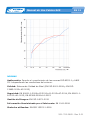
Global Attenuation for band white noise between 250 and 8000 Hz: 36 dB.
Maximum Attenuation for white noise: 49.7 dB at 5000 Hz
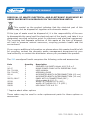
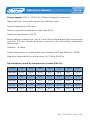
Dp insulation index by frequencies (model S40–B):
f (Hz) 100 125 160 200 250 315 400
Dp (dB) 10.5 24.8 28.5 29.5 29.8 28.7 30.5
f (Hz) 500 630 800 1000 1250 1600 2000
Dp (dB) 32.4 34.2 36.1 37.9 37.1 39.1 39.8
f (Hz) 2500 3150 4000 5000 6300 8000 10000
Dp (dB) 43.3 45.9 47.5 49.7 44.1 45.0 45.6

S40 User’s manual
501-700-MUM · Rev 2.01
EN 11
STANDARDS
Audiometry: Allows compliance with the ISO 8253-1 and ANSI S3.1 standards
depending on the surrounding conditions.
Quality: Sibel Quality Systems (EN ISO 9001:2008 and EN ISO
13485:2012+AC:2012)
Safety: EN 60601-1:2006+AC:2010+A1:2013+AC:2014, EN 60601-1-
6:2010+A1:2015, EN 62366:2008+A1:2015
Risk management: EN ISO 14971:2012
Information supplied by the manufacturer: EN 1041:2008
Symbols used: EN-ISO 15223-1:2016
Difference in levels, D’p (dB)
Frequency, 1 (Hz)

S40 User’s manual
501-700-MUM · Rev 2.01
EN 12
3. OPERATING PRINCIPLES
According to audiometry standards ANSI S3.1 and ISO 8253-1, audiometric
tests should be carried out in conditions where environmental noise does not
mask the results of these tests.
To this end, the booth is an acoustically-isolated enclosure where interior
background noise is very low compared to outside noise, allowing audiometric
tests to be performed correctly.
The booth has panels that contain different layers of sound-attenuating ma-
terial. The basic principle that produces the sound attenuation is known as
the law of mass. Other considerations to take into account in order to have
good sound attenuation are based on the suitable combination of materials, as
well as their dimensions, all of which avoids undesirable effects such, as the
matching effect. (For further information, consult soundproong and Acoustic
conventions).
4. TREATMENT, PREVENTATIVE AND CORRECTIVE MAINTENANCE
Like any other piece of equipment, the S40 soundproof booth requires treat-
ment and maintenance, to guarantee the reliability and accuracy of the func-
tions for which it has been designed. This implies carrying out a series of
routine tasks.
4.1. TREATMENT
The treatment is the action of maintaining the equipment in good working
order; the person performing this task does not require any specic technical
training, except knowledge of how to handle the equipment and its functions.
Normally, this will be performed by the user of the equipment. The operations
to be performed are:
The outside of the booth should be cleaned with soap and water, and then
dried. On the inside of the booth, the foam walls and carpeted oor may be
cleaned with a conventional vacuum cleaner: the plastic parts and the window
may be cleaned with soap and water.
Do not use abrasive or solvent substances that may damage the nish of the
booth.

S40 User’s manual
501-700-MUM · Rev 2.01
EN 13
4.2. PREVENTATIVE MAINTENANCE
Preventative maintenance consists of all those actions that keep the equip-
ment in good working order.
4.2.1. MONITORING
The user should periodically monitor the condition of the booth, the internal
lighting, the door lock and the state of the interconnections. Check that there
are no broken elements or external damage.
4.2.2. INSPECTING THE INTERCONNECTIONS
Biannually, check that the interconnections function correctly using an au-
diometer, and verify that they do not produce sounds that may reduce the
reliability of the audiometric tests.
4.3. CORRECTIVE MAINTENANCE
The corrective maintenance consists of leaving the equipment in good
working order, when poor operation or improper use may have decreased its
functionality or may have required repairs.
If a malfunction that impedes normal operation of the equipment is detected,
contact Sibel, S.A.U. after-sales service, specifying, as detailed as possible,
the nature of the anomaly.
-
 1
1
-
 2
2
-
 3
3
-
 4
4
-
 5
5
-
 6
6
-
 7
7
-
 8
8
-
 9
9
-
 10
10
-
 11
11
-
 12
12
-
 13
13
-
 14
14
-
 15
15
-
 16
16
-
 17
17
-
 18
18
-
 19
19
-
 20
20
-
 21
21
-
 22
22
-
 23
23
-
 24
24
-
 25
25
-
 26
26
-
 27
27


Sibelmed S40-B Manual de usuario
- Tipo
- Manual de usuario
en otros idiomas
- English: Sibelmed S40-B User manual
Otros documentos
-
Gima 53551 El manual del propietario
-
 Interacoustics AA222 Instrucciones de operación
-
Volvo 2012 Volvo On Call
-
Volvo C30 2009 Manual del propietario
-
Trust eeWave S40 Guía de instalación
-
Caterpillar CAT S40 Instrucciones de operación
-
Matrix G7-S40 El manual del propietario
-
Canon PowerShot S30 El manual del propietario
-
-
Volvo RTI Instrucciones de operación
