


CMM-40 – INSTRUKCJA OBSŁUGI
2
Multimetr TRMS CMM-40 przeznaczony jest do pomiaru napię-
cia stałego i zmiennego, prądu stałego i zmiennego, rezystancji, po-
jemności elektrycznej, częstotliwości (w elektryce i elektronice), cy-
klu roboczego (wypełnienia), a także testowania diod, ciągłości po-
łączeń oraz pomiaru temperatury.
Do najważniejszych cech przyrządu CMM-40 należą:
automatyczna lub ręczna zmiana zakresów,
funkcja HOLD umożliwiająca odczyt pomiarów przy niedosta-
tecznym oświetleniu lub w trudno dostępnych miejscach,
funkcja REL umożliwiająca dokonywanie pomiarów względ-
nych,
funkcja MAX/MIN umożliwiająca wyświetlanie wartości maksy-
malnej i minimalnej,
funkcja zatrzymania wartości szczytowej,
pamięć 2000 wyników pomiarów,
sygnalizacja dźwiękowa ciągłości obwodu (Beeper),
samoczynne wyłączanie nieużywanego przyrządu ,
wyświetlacz 4 ¾ cyfry,
obudowa dwukomponentowa, wodoodporna.

CMM-40 – INSTRUKCJA OBSŁUGI
3
SPIS TREŚCI
1 Wstęp ............................................................................ 5
2 Bezpieczeństwo ........................................................... 6
2.1 Międzynarodowe symbole bezpieczeństwa ........................ 8
3 Przygotowanie miernika do pracy .............................. 8
4 Opis funkcjonalny ........................................................ 9
4.1 Gniazda pomiarowe i elementy wyboru funkcji pomiarowej 9
4.1.1 Gniazda ..................................................................... 10
4.1.2 Elementy wyboru funkcji pomiarowej .......................... 10
4.2 Wyświetlacz ciekłokrystaliczny (LCD) ............................... 12
4.3 Przewody ......................................................................... 14
5 Pomiary ....................................................................... 14
5.1 Pomiar napięcia stałego ................................................... 14
5.2 Pomiar napięcia przemiennego ........................................ 15
5.3 Pomiar napięcia w [mV] .................................................... 16
5.4 Pomiar prądu stałego ....................................................... 17
5.5 Pomiar prądu przemiennego (częstotliwość, cykl roboczy) .. 18
5.6 Pomiar rezystancji ............................................................ 19
5.7 Test ciągłości obwodu ...................................................... 19
5.8 Test diod .......................................................................... 20
5.9 Pomiar pojemności ........................................................... 21
5.10 Pomiar temperatury .......................................................... 21
5.11 Pomiar częstotliwości lub% cyklu roboczego (wypełnienia) ...... 22
5.12 Pomiar pętli prądowej 4 ~ 20mA% .................................... 22
6 Funkcje specjalne ...................................................... 23
6.1 Ręczna zmiana podzakresów ........................................... 23
6.2 Tryb MAX/MIN .................................................................. 23
6.3 Tryb pomiaru względnego ................................................ 24
6.4 Funkcja HOLD .................................................................. 24
6.5 Funkcja zatrzymania wartości szczytowej PEAK HOLD .......... 24
6.6 Podświetlenie wyświetlacza .............................................. 25
6.7 Zapisywanie danych ......................................................... 25
6.8 Kasowanie pamięci .......................................................... 26

CMM-40 – INSTRUKCJA OBSŁUGI
4
6.9 Przywoływanie wyników z pamięci ................................... 26
6.10 Konfiguracja parametrów .................................................. 27
6.11 AC + DC ........................................................................... 27
7 Wymiana baterii ......................................................... 28
8 Wymiana bezpieczników ........................................... 29
9 Utrzymanie i konserwacja ......................................... 30
10 Magazynowanie ......................................................... 31
11 Rozbiórka i utylizacja ................................................ 31
12 Dane techniczne ........................................................ 32
12.1 Dane podstawowe ............................................................ 32
12.2 Dane eksploatacyjne ........................................................ 35
13 Producent ................................................................... 36

CMM-40 – INSTRUKCJA OBSŁUGI
5
1 Wstęp
Dziękujemy za zakup multimetru firmy Sonel. Miernik CMM-40
jest nowoczesnym, wysokiej jakości przyrządem pomiarowym, ła-
twym i bezpiecznym w obsłudze. Jednak przeczytanie niniejszej in-
strukcji pozwoli uniknąć błędów przy pomiarach i zapobiegnie
ewentualnym problemom przy obsłudze miernika.
W niniejszej instrukcji posługujemy się dwoma rodzajami
ostrzeżeń. Są to teksty w ramkach, opisujące możliwe zagrożenia
zarówno dla użytkownika, jak i miernika. Teksty rozpoczynające się
słowem ‘OSTRZEŻENIE:’ opisują sytuacje, w których może dojść
do zagrożenia życia lub zdrowia, jeżeli nie przestrzega się instrukcji.
Słowo ‘UWAGA!’ rozpoczyna opis sytuacji, w której niezastoso-
wanie się do instrukcji grozi uszkodzeniem przyrządu.
OSTRZEŻENIE:
Miernik CMM-40 jest przeznaczony do pomiarów prądu oraz
napięcia stałego i przemiennego, częstotliwości, rezystancji,
pojemności i temperatury, a także testów diod i ciągłości.
Każde inne zastosowanie niż podane w tej instrukcji może
spowodować uszkodzenie przyrządu i być źródłem poważ-
nego niebezpieczeństwa dla użytkownika.
OSTRZEŻENIE:
Miernik CMM-40 może być używany jedynie przez wykwalifi-
kowane osoby posiadające odpowiednie uprawnienia do
prac przy instalacjach elektrycznych. Posługiwanie się mier-
nikiem przez osoby nieuprawnione może spowodować
uszkodzenie przyrządu i być źródłem poważnego niebezpie-
czeństwa dla użytkownika.

CMM-40 – INSTRUKCJA OBSŁUGI
6
2 Bezpieczeństwo
Aby zapewnić odpowiednią obsługę i poprawność uzy-
skiwanych wyników należy przestrzegać następujących zaleceń:
przed rozpoczęciem eksploatacji miernika należy dokładnie za-
poznać się z niniejszą instrukcją,
przyrząd powinien być obsługiwany wyłącznie przez osoby od-
powiednio wykwalifikowane i przeszkolone w zakresie BHP,
należy zachować dużą ostrożność przy pomiarze napięć prze-
kraczających 40VDC lub 20VAC RMS gdyż stanowią one po-
tencjalne zagrożenie porażeniem,
przed przystąpieniem do pomiarów należy ustawić przełącznik
funkcji w odpowiednim położeniu,
w trakcie pomiarów napięcia nie należy przełączać urządzenia
w tryb pomiaru prądu lub rezystancji,
nie wolno przekraczać maksymalnego dopuszczalnego zakresu
napięcia wejściowego dla żadnej funkcji,
nie wolno podłączać napięcia do miernika kiedy wybrana jest
funkcja rezystancji,
w przypadku zmiany zakresów zawsze należy odłączyć prze-
wody pomiarowe od mierzonego obwodu,
nie wolno przekraczać maksymalnych limitów sygnału wejścio-
wego,
niedopuszczalne jest używanie:
miernika, który uległ uszkodzeniu i jest całkowicie lub czę-
ściowo niesprawny
przewodów z uszkodzoną izolacją
miernika przechowywanego zbyt długo w złych warunkach
(np. zawilgoconego)
naprawy mogą być wykonywane wyłącznie przez autoryzowany
serwis.
OSTRZEŻENIE:
Przed użyciem przyrządu należy dokładnie przeczytać niniej-
szą instrukcję i zastosować się do przepisów bezpieczeń-
stwa i zaleceń producenta.

CMM-40 – INSTRUKCJA OBSŁUGI
7
OSTRZEŻENIE:
Nigdy nie wolno przystępować do pomiarów, jeżeli użytkow-
nik ma mokre lub wilgotne dłonie.
OSTRZEŻENIE:
Nie wolno dokonywać pomiarów w atmosferze grożącej wy-
buchem (np. w obecności gazów palnych, oparów, pyłów,
itp.). W przeciwnym razie używanie miernika w tych warun-
kach może wywołać iskrzenia i spowodować eksplozję.
UWAGA!
Wartości graniczne sygnału wejściowego
Funkcja
Maksymalna wartość
wejściowa
V DC lub V AC
1000V DC/AC rms
mA AC/DC
Bezpiecznik szybki 500mA 1000V
A AC/DC
Bezpiecznik szybki 10A 1000V
(20A maksymalnie przez 30 se-
kund co 15 minut)
Częstotliwość, rezystancja,
pojemność elektryczna, cykl
roboczy, test diody, ciągłość
1000V DC/AC rms
Temperatura
1000V DC/AC rms
Ochrona przed skokami napięcia: wartość szczytowa 8kV zgodnie
z IEC 61010

CMM-40 – INSTRUKCJA OBSŁUGI
8
2.1 Międzynarodowe symbole bezpieczeństwa
Niniejszy symbol, umieszczony w pobliżu innego symbolu
lub gniazda wskazuje, że użytkownik winien zapoznać się
z dalszymi informacjami zamieszczonymi w instrukcji
obsługi.
Niniejszy symbol, umieszczony w pobliżu gniazda
wskazuje, że w warunkach normalnego użytkowania
istnieje możliwość wystąpienia niebezpiecznych napięć.
Podwójna izolacja
3 Przygotowanie miernika do pracy
Po zakupie miernika należy sprawdzić kompletność zawartości
opakowania.
Przed przystąpieniem do wykonywania pomiarów należy:
upewnić się, że stan baterii pozwoli na wykonanie pomiarów,
sprawdzić czy obudowa miernika i izolacja przewodów pomia-
rowych nie są uszkodzone,
dla zapewnienia jednoznaczności wyników pomiarów zaleca się
do gniazda COM podłączać przewód czarny a do pozostałych
gniazd przewód czerwony.
OSTRZEŻENIE:
Podłączanie nieodpowiednich lub uszkodzonych przewodów
grozi porażeniem niebezpiecznym napięciem.

CMM-40 – INSTRUKCJA OBSŁUGI
9
4 Opis funkcjonalny
4.1 Gniazda pomiarowe i elementy wyboru funkcji
pomiarowej
CMM-40

CMM-40 – INSTRUKCJA OBSŁUGI
10
4.1.1 Gniazda
7 gniazda pomiarowe μA, mA oraz 10A
Wejścia pomiarowe dla pomiarów prądów stałych i przemien-
nych.
8 gniazdo pomiarowe COM
Wejście pomiarowe wspólne dla wszystkich funkcji pomiaro-
wych.
9 gniazdo pomiarowe ΩCAPV°F°CHz%
Wejście pomiarowe dla pozostałych pomiarów oprócz prą-
dów.
4.1.2 Elementy wyboru funkcji pomiarowej
1 wyświetlacz LCD
2 STORE ( RECALL)
Wpis wyniku do pamięci (wywołanie wyniku z pamięci)
3 przycisk MAX/MIN
Wyświetlanie wartości maksymalnej i minimalnej
4 przycisk MODE
Zmiana trybu pomiaru
5 przycisk RANGE
Ręczna zmiana zakresu pomiarowego

CMM-40 – INSTRUKCJA OBSŁUGI
11
6 przełącznik obrotowy
Wybór funkcji:
μA – pomiar prądu stałego i przemiennego do 4000μA
4~20mA% – pomiar prądu pętli 4…20mA
mA – pomiar prądu stałego i przemiennego do 400mA
10AHz% – pomiar prądu stałego i przemiennego do 10A,
częstotliwości, cyklu roboczego (wypełnienia)
OFF – miernik wyłączony
VACHz% – pomiar napięcia przemiennego, częstotliwości,
cyklu roboczego
VDC – pomiar napięcia stałego
mV – pomiar napięcia stałego i przemiennego do 400mV
Hz% – pomiar częstotliwości, cyklu roboczego (wypełnie-
nia)
ΩCAP – pomiar rezystancji, ciągłości, pojemności i
test diod
Temp – pomiar temperatury w stopniach Celsjusza lub
Fahrenheita
10 przycisk
Podświetlenie wyświetlacza
11 przycisk EXIT (AC+DC)
Wyjście
Pomiar wartości trms
12 przycisk HOLD
Zatrzymanie wyniku pomiaru na wyświetlaczu
13 przycisk REL
Pomiar względny

CMM-40 – INSTRUKCJA OBSŁUGI
12
4.2 Wyświetlacz ciekłokrystaliczny (LCD)
Wyświetlacz ciekłokrystaliczny miernika CMM-40
– symbol włączenia testu ciągłości
– symbol włączenia testu diod
– słaba bateria
n – nano (10-9) (pojemność elektryczna)
µ – mikro (10-6) (ampery, pojemność)
m – milli (10-3) (volty, ampery)
A – ampery
k – kilo (103) (ohmy)
F – farady (pojemność elektryczna)
M – mega (106) (ohmy)
–ohmy
Hz – hertz (częstotliwość)
% – procent (współczynnik wypełnienia)

CMM-40 – INSTRUKCJA OBSŁUGI
13
DC, AC – napięcie (prąd) stałe, zmienne
ºC – stopnie Celsjusza
ºF – stopnie Fahrenheita
MAX – maksimum
MIN – minimum
No. – numer wyniku w pamięci
S – sekunda
SET – ustawianie parametrów pomiaru
AC +DC – prąd zmienny + prąd stały
TRMS – rzeczywista wartość skuteczna prądu
STO – zapisz
RCL – przywołaj
AUTO – symbol automatycznego wyboru podzakresu
PEAK – wartość szczytowa
V – wolty
– pomiar względny
HOLD – symbol włączenia funkcji HOLD

CMM-40 – INSTRUKCJA OBSŁUGI
14
4.3 Przewody
Producent gwarantuje poprawność wskazań jedynie przy użyciu
firmowych przewodów.
OSTRZEŻENIE:
Podłączanie nieodpowiednich przewodów grozi porażeniem
wysokim napięciem lub błędami pomiarowymi.
5 Pomiary
Należy dokładnie zapoznać się z treścią tego rozdziału, ponie-
waż zostały w nim opisane sposoby wykonywania pomiarów i pod-
stawowe zasady interpretacji wyników.
5.1 Pomiar napięcia stałego
UWAGA:
Nie należy mierzyć napięcia stałego w momencie, gdy silnik
elektryczny w obwodzie jest włączany lub wyłączany. Mogło-
by to spowodować duże skoki napięcia i w rezultacie uszko-
dzenie miernika.
Aby wykonać pomiar napięcia należy:
ustawić przełącznik obrotowy w pozycji VDC,
w razie potrzeby przyciskiem RANGE ustawić ręcznie zakres
pomiarowy,
podłączyć czerwony przewód pomiarowy do gniazda
ΩCAPV°F°CHz% a czarny do gniazda COM,
przyłożyć ostrza sond do punktów pomiarowych; sonda czer-
wona powinna być przyłożona do punktu o wyższym potencja-
le,
odczytać wynik pomiaru na wyświetlaczu,
po zakończeniu pomiarów wyjąć przewody z gniazd pomiaro-
wych miernika.

CMM-40 – INSTRUKCJA OBSŁUGI
15
5.2 Pomiar napięcia przemiennego
OSTRZEŻENIE:
Niebezpieczeństwo porażenia. Końcówki sondy mogą nie
być dostatecznie długie, aby dosięgnąć elementów pod na-
pięciem wewnątrz niektórych przyłączy sieciowych 240V dla
urządzeń elektrycznych, ponieważ styki są umieszczone w
głębi gniazdek. Na skutek tego odczyt będzie wskazywał war-
tość 0V, kiedy gniazdo w rzeczywistości może znajdować się
pod napięciem. Należy się upewnić, że końcówki sondy do-
tykają metalowych styków wewnątrz gniazda zanim użyt-
kownik założy, że gniazdo nie znajduje się pod napięciem.
UWAGA:
Nie należy mierzyć napięcia przemiennego w momencie, gdy
silnik elektryczny w obwodzie jest włączany lub wyłączany.
Mogłoby to spowodować duże skoki napięcia i w rezultacie
uszkodzenie miernika.
Aby wykonać pomiar napięcia należy:
ustawić przełącznik obrotowy w pozycji VACHz%,
w razie potrzeby przyciskiem RANGE ustawić ręcznie zakres
pomiarowy,
podłączyć czerwony przewód pomiarowy do gniazda
ΩCAPV°F°CHz% a czarny do gniazda COM,
przyłożyć ostrza sond do punktów pomiarowych,
odczytać wynik pomiaru na wyświetlaczu,
nacisnąć przycisk MODE celem wyświetlenia wartości “Hz”,
odczytać wartość częstotliwości na wyświetlaczu głównym,
nacisnąć ponownie przycisk MODE celem wyświetlenia warto-
ści “%”,
odczytać wartość% dla cyklu roboczego na wyświetlaczu
głównym,

CMM-40 – INSTRUKCJA OBSŁUGI
16
nacisnąć przycisk EXIT i przytrzymać go przez dwie sekundy,
aby przejść do funkcji AC+DC,
wykonać pomiar rzeczywistej wartości skutecznej prądu stałe-
go i zmiennego,
po zakończeniu pomiarów wyjąć przewody z gniazd pomiaro-
wych miernika.
5.3 Pomiar napięcia w [mV]
UWAGA:
Nie należy mierzyć napięcia w [mV] w momencie, gdy silnik
elektryczny w obwodzie jest włączany lub wyłączany. Mogło-
by to spowodować duże skoki napięcia i w rezultacie uszko-
dzenie miernika.
ustawić przełącznik obrotowy w pozycji mV,
nacisnąć przycisk MODE w celu wyświetlenia wartości DC lub
AC,
w zakresie AC nacisnąć przycisk EXIT i przytrzymać go przez
dwie sekundy, aby przejść do funkcji AC+DC,
podłączyć czerwony przewód pomiarowy do gniazda
ΩCAPV°F°CHz% a czarny do gniazda COM,
przyłożyć ostrza sond do punktów pomiarowych; dla napięcia
stałego sonda czerwona powinna być przyłożona do punktu o
wyższym potencjale,
odczytać wynik pomiaru na wyświetlaczu,
po zakończeniu pomiarów wyjąć przewody z gniazd pomiaro-
wych miernika.

CMM-40 – INSTRUKCJA OBSŁUGI
17
5.4 Pomiar prądu stałego
UWAGA:
Nie należy wykonywać pomiarów prądu 20A przez czas dłuż-
szy niż 30 sekund. Przekroczenie tego czasu może spowo-
dować uszkodzenie miernika i/lub przewodów pomiarowych.
Aby wykonać pomiar prądu należy:
podłączyć czarny przewód pomiarowy do gniazda COM,
dla pomiarów prądu do 4000µA DC należy ustawić przełącznik
funkcji w położeniu µA i podłączyć czerwony przewód pomia-
rowy do gniazda µA/mA,
dla pomiarów prądu do 400mA DC należy ustawić przełącznik
funkcji w położeniu mA i podłączyć czerwony przewód pomia-
rowy do gniazda µA/mA,
dla pomiarów prądu do 20A DC należy ustawić przełącznik
funkcji w położeniu 10AHz% i podłączyć czerwony przewód
pomiarowy do gniazda 10A,
odłączyć zasilanie od poddawanego pomiarom obwodu, a na-
stępnie miernik włączyć szeregowo w obwód w punkcie, w któ-
rym ma być mierzony prąd,
przyłożyć ostrze czarnej sondy pomiarowej do ujemnego bie-
guna obwodu a ostrze czerwonej sondy pomiarowej do dodat-
niego bieguna obwodu,
włączyć zasilanie obwodu,
odczytać wynik pomiaru na wyświetlaczu,
po zakończeniu pomiarów wyjąć przewody z gniazd pomiaro-
wych miernika.

CMM-40 – INSTRUKCJA OBSŁUGI
18
5.5 Pomiar prądu przemiennego (częstotliwość, cykl
roboczy)
UWAGA:
Nie należy wykonywać pomiarów prądu 20A przez czas dłuż-
szy niż 30 sekund. Przekroczenie tego czasu może spowo-
dować uszkodzenie miernika i/lub przewodów pomiarowych.
Aby wykonać pomiar prądu należy:
podłączyć czarny przewód pomiarowy do gniazda COM,
dla pomiarów prądu do 4000µA AC należy ustawić przełącznik
funkcji w położeniu µA i podłączyć czerwony przewód pomia-
rowy do gniazda µA/mA,
dla pomiarów prądu do 400mA AC należy ustawić przełącznik
funkcji w położeniu mA i podłączyć czerwony przewód pomia-
rowy do gniazda µA/mA,
dla pomiarów prądu do 20A AC należy ustawić przełącznik
funkcji w położeniu 10AHz% i podłączyć czerwony przewód
pomiarowy do gniazda 10A,
nacisnąć przycisk MODE w celu wyświetlenia wartości AC na
wyświetlaczu,
odłączyć zasilanie od poddawanego pomiarom obwodu, a na-
stępnie miernik włączyć szeregowo w obwód w punkcie, w któ-
rym ma być mierzony prąd,
przyłożyć ostrze czarnej sondy pomiarowej do neutralnego
bieguna obwodu a ostrze czerwonej sondy pomiarowej do bie-
guna obwodu będącego pod napięciem,
włączyć zasilanie obwodu,
odczytać wynik pomiaru na wyświetlaczu, w zakresie 10A AC
prawy wyświetlacz pomocniczy przedstawia częstotliwość,
nacisnąć i przytrzymać przycisk MODE celem wyświetlenia
wartości Hz,
odczytać wartość częstotliwości na wyświetlaczu,
na krótko nacisnąć ponownie przycisk MODE w celu wyświe-
tlenia wartości%,
odczytać wartość% cyklu roboczego na wyświetlaczu,

CMM-40 – INSTRUKCJA OBSŁUGI
19
nacisnąć i przytrzymać przycisk MODE, aby powrócić do po-
miaru prądu,
nacisnąć przycisk EXIT i przytrzymać go przez dwie sekundy,
aby przejść do funkcji AC+DC, wykonać pomiar rzeczywistej
wartości skutecznej prądu stałego i zmiennego,
po zakończeniu pomiarów wyjąć przewody z gniazd pomiaro-
wych miernika.
5.6 Pomiar rezystancji
OSTRZEŻENIE:
Nie wolno dokonywać pomiarów w obwodzie będącym pod
napięciem. Kondensatory należy rozładować.
Aby wykonać pomiar rezystancji należy:
ustawić przełącznik obrotowy w pozycji ΩCAP,
podłączyć czerwony przewód pomiarowy do gniazda
ΩCAPV°F°CHz% a czarny do gniazda COM,
nacisnąć przycisk MODE, aby wyświetlić na wyświetlaczu,
w razie potrzeby przyciskiem RANGE ustawić ręcznie zakres
pomiarowy,
przyłożyć ostrza sond do punktów pomiarowych; najlepiej jest
rozłączyć jedną stronę testowanego elementu, tak aby pozo-
stała część obwodu nie zakłócała odczytu wartości rezystancji,
odczytać wynik pomiaru na wyświetlaczu,
po zakończeniu pomiarów wyjąć przewody z gniazd pomiaro-
wych miernika.
5.7 Test ciągłości obwodu
OSTRZEŻENIE:
Nie wolno dokonywać pomiarów w obwodzie będącym pod
napięciem. Kondensatory należy rozładować.
Aby wykonać test ciągłości obwodu należy:

CMM-40 – INSTRUKCJA OBSŁUGI
20
ustawić przełącznik obrotowy w pozycji ΩCAP,
podłączyć czerwony przewód pomiarowy do gniazda
ΩCAPV°F°CHz% a czarny do gniazda COM,
nacisnąć przycisk MODE, aby wyświetlić i na wyświetla-
czu,
przyłożyć ostrza sond do punktów pomiarowych,
odczytać wynik pomiaru na wyświetlaczu; sygnał dźwiękowy
pojawia się przy wartościach rezystancji poniżej ok. 35, jeżeli
obwód jest otwarty, wyświetlacz wskaże symbol OL,
po zakończeniu pomiarów wyjąć przewody z gniazd pomiaro-
wych miernika.
5.8 Test diod
OSTRZEŻENIE:
Nie wolno dokonywać pomiarów w obwodzie będącym pod
napięciem. Kondensatory należy rozładować.
Aby wykonać test diody należy:
ustawić przełącznik obrotowy w pozycji ΩCAP,
podłączyć czerwony przewód pomiarowy do gniazda
ΩCAPV°F°CHz% a czarny do gniazda COM,
nacisnąć przycisk MODE, aby wyświetlić i V na wyświetla-
czu,
przyłożyć ostrza sond do diody: czerwona sonda powinna być
przyłożona do anody a czarna do katody,
odczytać wynik testu na wyświetlaczu: wyświetlane jest napię-
cie przewodzenia, które dla typowej diody krzemowej wynosi
ok. 0,7V a dla diody germanowej ok. 0,3V; jeżeli dioda spola-
ryzowana jest w kierunku zaporowym lub jest przerwa w ob-
wodzie, na wyświetlaczu pojawi się odczyt OL, w przypadku
diody zwartej, miernik wskaże wartość bliską 0V,
po zakończeniu pomiarów wyjąć przewody z gniazd pomiaro-
wych miernika.

CMM-40 – INSTRUKCJA OBSŁUGI
21
5.9 Pomiar pojemności
OSTRZEŻENIE:
Nie wolno dokonywać pomiarów w obwodzie będącym pod
napięciem. Kondensatory należy rozładować.
Aby wykonać pomiar należy:
ustawić przełącznik obrotowy w pozycji ΩCAP,
podłączyć czerwony przewód pomiarowy do gniazda
ΩCAPV°F°CHz% a czarny do gniazda COM,
nacisnąć przycisk MODE celem wyświetlenia F,
w razie potrzeby przyciskiem RANGE ustawić ręcznie zakres
pomiarowy,
przyłożyć ostrza sond do testowanego kondensatora,
odczytać wynik pomiaru na wyświetlaczu,
po zakończeniu pomiarów wyjąć przewody z gniazd pomiaro-
wych miernika.
5.10 Pomiar temperatury
Aby wykonać pomiar należy:
ustawić przełącznik obrotowy w pozycji Temp,
podłączyć sondę temperatury do ujemnego gniazda COM oraz
dodatniego gniazda ΩCAPV°F°CHz%, przestrzegając
biegunowości,
nacisnąć przycisk MODE aby wybrać jednostkę pomiaru: °C
lub °F,
przyłożyć głowicę sondy temperatury do testowanego
urządzenia. Kontakt głowicy z mierzoną częścią testowanego
urządzenia należy utrzymywać dopóki odczyt się nie
ustabilizuje (po około 30 sekundach),
odczytać wynik pomiaru na wyświetlaczu,
po zakończeniu pomiarów wyjąć przewody sondy z gniazd
pomiarowych miernika.

CMM-40 – INSTRUKCJA OBSŁUGI
22
Uwaga:
Sonda temperatury jest wyposażona w mini-złącze typu K.
Adapter do połączenia mini-złącza i wtyku bananowego do-
starczany jest dla potrzeb połączenia z bananowymi gniaz-
dami wejściowymi.
5.11 Pomiar częstotliwości lub% cyklu roboczego (wy-
pełnienia)
Aby wykonać pomiar należy:
ustawić przełącznik obrotowy w pozycji Hz%,
podłączyć czerwony przewód pomiarowy do gniazda
ΩCAPV°F°CHz%a czarny do gniazda COM,
przyłożyć ostrza sond do testowanego obwodu,
w razie potrzeby przyciskiem RANGE ustawić ręcznie zakres
pomiarowy,
odczytać wynik pomiaru na wyświetlaczu,
nacisnąć przycisk MODE, aby wyświetlić%,
odczytać wartość% cyklu roboczego na wyświetlaczu,
po zakończeniu pomiarów wyjąć przewody z gniazd pomiaro-
wych miernika.
5.12 Pomiar pętli prądowej 4 ~ 20mA%
Aby wykonać pomiar należy:
skonfigurować i podłączyć urządzenie zgodnie z opisem dla
pomiarów DC mA,
ustawić obrotowy przełącznik funkcji w położeniu 4~20mA%,
miernik wyświetli prąd pętli jako wartość% przy 0mA=-25%,
4mA=0%, 20mA=100%, oraz 24mA=125%.

CMM-40 – INSTRUKCJA OBSŁUGI
23
6 Funkcje specjalne
6.1 Ręczna zmiana podzakresów
Kiedy miernik zostaje włączony po raz pierwszy, przechodzi w
tryb automatycznego wyboru zakresu. W trybie tym automatycznie
zostaje wybrany najlepszy zakres dla wykonywanych pomiarów i
jest to zazwyczaj najlepszy tryb dla większości pomiarów. W przy-
padku pomiarów, które wymagają ręcznych ustawień zakresu, na-
leży wykonać poniższe czynności:
nacisnąć przycisk RANGE. Symbol AUTO na wyświetlaczu
zgaśnie,
nacisnąć ponownie przycisk RANGE, który pozwala na
przejście pomiędzy dostępnymi zakresami oraz wybranie
pożądanego zakresu,
aby wyjść z trybu ręcznego wyboru zakresu i powrócić do
automatycznego wyboru zakresu nacisnąć przycisk EXIT.
Uwaga:
Ręczny wybór zakresu nie jest stosowany w przypadku
funkcji pomiarów temperatury, ciągłości, testu diody, cyklu
roboczego, mV, prądu 4~20mA oraz 10A.
6.2 Tryb MAX/MIN
Nacisnąć przycisk MAX/MIN, aby uruchomić tryb zapisu
MAX/MIN. Na lewym wyświetlaczu pojawi się ikona MAX. Wyświe-
tlacz pomocniczy miernika przedstawi maksymalny odczyt, który
zostanie zaktualizowany dopiero po wystąpieniu nowej wartości
“max”. Na prawym wyświetlaczu pojawi się ikona MIN. Wyświetlacz
pomocniczy miernika przedstawi minimalny odczyt, który zostanie
zaktualizowany dopiero po wystąpieniu nowej wartości “min”.
Aby wyjść z trybu MAX/MIN należy nacisnąć przycisk EXIT.

CMM-40 – INSTRUKCJA OBSŁUGI
24
6.3 Tryb pomiaru względnego
Funkcja pomiaru względnego umożliwia dokonywanie pomia-
rów względem zapisanej wartości odniesienia. Wartość odniesienia
napięcia, prądu, itd. może zostać zapisana, a pomiary mogą być
dokonywane w porównaniu do tej wartości. Wyświetlana wartość
jest różnicą pomiędzy wartością odniesienia a wartością mierzoną.
Uwaga:
Tryb względny nie jest stosowany w funkcjach 4~20mA, te-
ście diody i ciągłości.
Aby wykonać pomiar w trybie względnym należy:
wykonać pomiar zgodnie z opisem przedstawionym w
instrukcji obsługi,
nacisnąć przycisk REL w celu zapisania odczytu przedstawio-
nego na wyświetlaczu; na wyświetlaczu pojawi się symbol
,
na lewym wyświetlaczu pomocniczym pojawi się różnica
wartości wartość bieżąca pomiaru, na prawym wyświetlaczu
pomocniczym pojawi się odczyt początkowy, na wyświetlaczu
głównym przedstawiony zostanie odczyt pomiaru wartości
względnej w trybie REL TEST,
aby wyjść z trybu względnego należy nacisnąć przycisk EXIT.
6.4 Funkcja HOLD
Funkcja ta służy do zatrzymania wyniku pomiaru na wyświetla-
czu, co jest możliwe poprzez naciśnięcie przycisku HOLD. Kiedy
funkcja jest włączona, na wyświetlaczu pojawia się symbol HOLD.
Celem powrotu do normalnego trybu funkcjonowania urządzenia
należy ponownie nacisnąć przycisk HOLD.
6.5 Funkcja zatrzymania wartości szczytowej PEAK
HOLD
Funkcja PEAK HOLD wychwytuje wartość szczytową napięcia
lub prądu zmiennego (AC) oraz zmiennego ze składową stałą

CMM-40 – INSTRUKCJA OBSŁUGI
25
(AC+DC, patrz rozdz. 5.5). Miernik może wychwycić ujemne lub
dodatnie wartości szczytowe trwające 1 milisekundę.
Aby uaktywnić funkcję, należy przytrzymać przycisk PEAK
przez 2s (sygnalizowane dłuższym sygnałem dźwiękowym). Po
puszczeniu przycisku na ekranie pojawi się symbol PEAK. U góry
wyświetlacza pojawią się: wartości MAX na lewym wyświetlaczu
pomocniczym, zaś MIN na prawym wyświetlaczu pomocniczym.
Miernik będzie aktualizował wyświetlane dane za każdym ra-
zem, gdy wystąpi niższa ujemna lub wyższa dodatnia wartość
szczytowa.
Funkcja automatycznego wyłączenia zasilania zostanie w tym
trybie dezaktywowana.
Aby wyjść z trybu PEAK HOLD, nacisnąć przycisk EXIT lub wy-
brać inną funkcję pomiarową.
Uwaga:
W czasie gdy funkcja PEAK HOLD jest aktywna, nie działa au-
tomatyczne dobieranie zakresów, dlatego zaleca się urucha-
miać funkcję dopiero po podłączenia przewodów do punktu
pomiarowego. Uruchomienie funkcji PEAK HOLD przed podłą-
czeniem miernika do punktu mierzonego może powodować
wyświetlanie symboli przekroczenia zakresu.
6.6 Podświetlenie wyświetlacza
Aby włączyć podświetlenie wyświetlacza, nacisnąć przycisk .
Podświetlenie zostanie automatycznie wyłączone po upływie usta-
wionego przez użytkownika czasu. Aby wyjść z trybu podświetlenia
wyświetlacza, nacisnąć przycisk ponownie.
6.7 Zapisywanie danych
Aby zapisać wynik pomiaru należy:
w bieżącym trybie pomiarowym jednokrotnie nacisnąć przycisk
STORE, by wejść do trybu zapisu - w lewym górnym rogu
wyświetlacza pojawi się komunikat NO. XXXX, który określa
bieżący numer komórki pamięci (XXXX – numer komórki),

CMM-40 – INSTRUKCJA OBSŁUGI
26
nacisnąć przycisk PEAKHOLD, aby wybrać początkową
komórkę pamięci kolejnego zapisu (na lewym wyświetlaczu
0000 – od początku pamięci, XXXX – od kolejnej wolnej
komórki), na prawym wyświetlaczu pomocniczym pojawi się
komunikat XXXX, który określa ilość zapisanych komórek,
nacisnąć ponownie przycisk STORE, aby wprowadzić ustawie-
nia interwału czasowego funkcji - w lewym górnym rogu
wyświetlacza pojawi się wartość 0000 S, która oznacza
interwał czasowy zapisu danych. Naciskając przyciski + i –
można dokonać wyboru zakresu w granicach 0...255 sekund,
kiedy interwał czasowy zapisu danych wynosi 0000s, wówczas
należy ponownie nacisnąć przycisk STORE, aby przejść do
trybu zapisu ręcznego - nacisnąć ponownie przycisk STORE
celem dokonania jednokrotnego zapisu,
kiedy interwał czasowy zapisu danych wynosi od 1...255s,
wówczas należy ponownie nacisnąć przycisk STORE, aby
rozpocząć automatyczny zapis do pamięci. W lewym górnym
rogu podawana jest aktualna komórka pamięci, zapisywane
dane są wyświetlane w prawym górnym rogu.
Uwaga:
Ze względu na ograniczenia cyfrowe, wyświetlacz przedsta-
wia wyłącznie wartości czterocyfrowe.
aby wyjść z trybu zapisu należy na krótki moment nacisnąć
przycisk EXIT.
6.8 Kasowanie pamięci
Aby skasować całą pamięć należy:
kiedy zasilanie urządzenia jest wyłączone, nacisnąć przycisk
EXIT i przytrzymać go,
przestawić przełącznik z pozycji OFF na jakąkolwiek inną i
zwolnić przycisk EXIT - wyświetlacz zamiga trzykrotnie oraz
będzie trzykrotny sygnał dźwiękowy, co oznacza, że dane w
pamięci zostały skasowane.
6.9 Przywoływanie wyników z pamięci
Aby przywołać wyniki pomiarów z pamięci należy:

CMM-40 – INSTRUKCJA OBSŁUGI
27
nacisnąć przycisk STORE ( RECALL) i przytrzymać go przez
dwie sekundy celem wejścia do trybu wywoływania wyników –
na lewym górnym wyświetlaczu pojawi się wartość XXXX,
która oznacza bieżący numer komórki. W prawym górnym
rogu wyświetlacza pojawi się wartość XXXX, która oznacza
całkowitą liczbę zapisanych komórek,
za pomocą przycisków + i – można przeglądać kolejne
komórki pamięci z zapisanymi danymi na głównym
wyświetlacz,
nacisnąć przycisk HOLD (PeakHOLD) jednokrotnie celem
przeglądu danych od 0000 do XXXX w sposób ciągły,
aby wyjść z trybu nacisnąć przycisk EXIT.
6.10 Konfiguracja parametrów
Aby skonfigurować parametry pomiaru należy:
nacisnąć przycisk RANGE (SETUP) i przytrzymać go przez
dwie sekundy , aby wejść do trybu ustawiania parametrów,
przez krótką chwilę nacisnąć przycisk RANGE (SETUP) jeden
raz aby zmienić rodzaj ustawień,
Rodzaj ustawień obejmuje poniższe elementy (w sekwencji)
A: alarm dźwiękowy dla górnego limitu,
B: alarm dźwiękowy dla dolnego limitu,
C: czas do automatycznego wyłączenia zasilania,
D: sygnał dźwiękowy wyłączenia,
E: czas podświetlenia,
w celu wyboru parametrów stosować przyciski ←, +, -, →,
naciskać przycisk SET, aby przejść przez zawartości ustawień,
aż do wyjścia z ustawień do trybu pomiarowego;
zaktualizowana zawartość ustawień zostaje zapisana. W
przypadku naciśnięcia w tym czasie przycisku EXIT ustawienia
nie zostaną zapisane.
6.11 AC + DC
Funkcja działa we wszystkich trybach pomiarowych: VAC,
mV(AC), 10A(AC), mA(AC), μA(AC).
Nacisnąć przycisk EXIT (AC+DC) przez dwie sekundy w celu
wejścia do trybu testu prądu zmiennego i prądu stałego.

CMM-40 – INSTRUKCJA OBSŁUGI
28
Dokładność jest taka sama jak w pomiarze prądu zmiennego.
Wyświetlacz wyświetla mnemonik AC+DC.
W celu wyjścia z niniejszego trybu nacisnąć przycisk EXIT.
7 Wymiana baterii
Miernik CMM-40 jest zasilany z baterii 9V typu 6LR61.
Uwaga:
Dokonując pomiarów przy wyświetlonym mnemoniku baterii
należy się liczyć z dodatkowymi nieokreślonymi niepewno-
ściami pomiaru lub niestabilnym działaniem przyrządu.
OSTRZEŻENIE:
Pozostawienie przewodów w gniazdach podczas wymiany
baterii może spowodować porażenie niebezpiecznym napię-
ciem.
Aby wymienić baterię należy:
wyjąć przewody z gniazd pomiarowych i przełącznik obrotowy
ustawić w pozycji OFF,
otworzyć tylną pokrywę baterii poprzez odkręcenie dwóch
śrub (B) używając śrubokrętu krzyżakowego,
wyjąć rozładowaną baterię i włożyć nową przestrzegając bie-
gunowości,
założyć zdjętą pokrywę i przykręcić śruby mocujące.
OSTRZEŻENIE:
Aby uniknąć porażenia elektrycznego nie należy używać
miernika, jeżeli pokrywa baterii nie znajduje się na swoim
miejscu i nie jest prawidłowo zamocowana.

CMM-40 – INSTRUKCJA OBSŁUGI
29
Uwaga:
Jeżeli miernik nie funkcjonuje prawidłowo, należy sprawdzić
bezpieczniki oraz baterie, aby upewnić się, że znajdują się
one we właściwym stanie oraz są prawidłowo zamontowane
w urządzeniu.
8 Wymiana bezpieczników
OSTRZEŻENIE:
Pozostawienie przewodów w gniazdach podczas wymiany
bezpieczników może spowodować porażenie niebezpiecz-
nym napięciem.
Aby wymienić bezpiecznik należy:
wyjąć przewody z gniazd pomiarowych i przełącznik obrotowy
ustawić w pozycji OFF,
otworzyć tylną pokrywę baterii poprzez odkręcenie dwóch
śrub (B) używając śrubokrętu krzyżakowego,
wyjąć baterię,
odkręcić sześć śrub (A) mocujących tylną pokrywę,
delikatnie wyjąć stary bezpiecznik i zainstalować nowy w jego
uchwycie.
założyć na nowo i zabezpieczyć tylną pokrywę, baterię oraz
pokrywę baterii.
UWAGA!
Zawsze należy stosować bezpieczniki o właściwym rozmia-
rze i wartości (0,5A/1000V szybki bezpiecznik dla zakresu
400mA [SIBA 70-172-40], 10A/1000V szybki bezpiecznik dla
zakresu 20A [SIBA 50-199-06]).

CMM-40 – INSTRUKCJA OBSŁUGI
30
9 Utrzymanie i konserwacja
Miernik wielofunkcyjny został zaprojektowany z myślą o wielu
latach niezawodnego użytkowania, pod warunkiem przestrzegania
poniższych zaleceń dotyczących jego utrzymania i konserwacji:
1. MIERNIK MUSI BYĆ SUCHY. W razie zawilgocenia miernika,
należy go wytrzeć.
2. MIERNIK NALEŻY STOSOWAĆ ORAZ PRZECHOWYWAĆ
W NORMALNYCH TEMPERATURACH. Temperatury
skrajne mogą skrócić żywotność elektronicznych elementów
miernika oraz zniekształcić lub stopić elementy plastikowe.
3. Z MIERNIKIEM NALEŻY OBCHODZIĆ SIĘ OSTROŻNIE I
DELIKATNIE. Upadek miernika może spowodować usz-
kodzenie elektronicznych elementów miernika lub jego
obudowy.
4. MIERNIK MUSI BYĆ UTRZYMYWANY W CZYSTOŚCI. Od
czasu do czasu należy przetrzeć jego obudowę wilgotną
tkaniną. NIE wolno stosować środków chemicznych,
rozpuszczalników ani detergentów.

CMM-40 – INSTRUKCJA OBSŁUGI
31
5. NALEŻY STOSOAĆ WYŁĄCZNIE NOWE BATERIE
ZALECANEGO ROZMIARU I TYPU. Wyjąć z miernika stare
lub wyczerpane baterie, aby uniknąć ich wycieku i
uszkodzenia urządzenia.
6. JEŚLI MIERNIK MA BYĆ PRZEZ DŁUŻSZY OKRES CZASU
PRZECHOWYWANY, wówczas należy wyjąć z niego
baterie, aby zapobiec uszkodzeniu urządzenia.
Uwaga:
Układ elektroniczny miernika nie wymaga konserwacji.
10 Magazynowanie
Przy przechowywaniu przyrządu należy przestrzegać poniż-
szych zaleceń:
odłączyć od miernika przewody,
upewnić się, że miernik i akcesoria są suche,
przy dłuższym okresie przechowywania należy wyjąć baterię.
11 Rozbiórka i utylizacja
Zużyty sprzęt elektryczny i elektroniczny należy gromadzić se-
lektywnie, tj. nie umieszczać z odpadami innego rodzaju.
Zużyty sprzęt elektroniczny należy przekazać do punktu zbiórki
zgodnie z Ustawą o zużytym sprzęcie elektrycznym i elektronicz-
nym.
Przed przekazaniem sprzętu do punktu zbiórki nie należy sa-
modzielnie demontować żadnych części z tego sprzętu.
Należy przestrzegać lokalnych przepisów dotyczących wyrzu-
cania opakowań, zużytych baterii i akumulatorów.

CMM-40 – INSTRUKCJA OBSŁUGI
32
12 Dane techniczne
12.1 Dane podstawowe
„w.m.” w określeniu wartość mierzoną wzorcową.
Pomiar napięcia stałego
Zakres
Rozdzielczość
Dokładność
400,00mV
0,01mV
(0,06% w.m. + 4 cyfry)
4,0000V
0,0001V
40,000V
0,001V
400,00V
0,01V
1000,0V
0,1V
(0,1% w.m. + 5 cyfr)
Pomiar napięcia przemiennego (True RMS)
Zakres
Rozdzielczość
Dokładność
400,00mV
0,01mV
(1% w.m. + 40 cyfr)
4,0000V
0,0001V
(1% w.m. + 30 cyfr)
40,000V
0,001V
400,00V
0,01V
1000,0V
0,1V
Zakres częstotliwości 50...1000Hz
Pomiar prądu stałego
Zakres
Rozdzielczość
Dokładność
400,00μA
0,01μA
(1% w.m. + 3 cyfry)
4000,0μA
0,1μA
40,000mA
0,001mA
400,00mA
0,01mA
10,000A
0,001A
20A: maksymalnie 30 sekund przy ograniczonej dokładności

CMM-40 – INSTRUKCJA OBSŁUGI
33
Pomiar prądu przemiennego (True RMS)
Zakres
Rozdzielczość
Dokładność
400,00μA
0,01μA
(1,5% w.m. + 30 cyfr)
4000,0μA
0,1μA
40,000mA
0,001mA
400,00mA
0,01mA
10,000A
0,001A
20A: maksymalnie 30 sekund przy ograniczonej dokładności
Uwaga:
Dokładność została wyznaczone przy temperaturze w zakre-
sie od 18oC do 28oC i przy względnej wilgotności powietrza
niższej niż 75%. Dla prądu zniekształconego błąd jest więk-
szy o (2% odczytu + 2% pełnej skali), dla współczynnika
szczytu <3.0.
Pomiar rezystancji
Zakres
Rozdzielczość
Dokładność
400,00
0,01
(0,3% w.m. + 9 cyfr)
4,0000k
0,0001k
(0,3% w.m. + 4 cyfry)
40,000k
0,001k
400,00k
0,01k
4,0000M
0,0001M
40,000M
0,001M
(2% w.m. + 10 cyfr)
Pomiar pojemności
Zakres
Rozdzielczość
Dokładność
40,000nF
0,001nF
(3,5% w.m. + 40 cyfr)
400,00nF
0,01nF
4,0000μF
0,0001μF
(3,5% w.m. + 10 cyfr)
40,000μF
0,001μF
400,00μF
0,01μF
4000,0μF
0,1μF
(5% w.m. + 10 cyfr)
40,000mF
0,001mF

CMM-40 – INSTRUKCJA OBSŁUGI
34
Pomiar częstotliwości (w elektronice)
Zakres
Rozdzielczość
Dokładność
40,000Hz
0,001Hz
(0,1% w.m. + 1 cyfra)
400,00Hz
0,01Hz
4,0000kHz
0,0001kHz
40,000kHz
0,001kHz
400,00kHz
0,01kHz
4,0000MHz
0,0001MHz
40,000MHz
0,001MHz
100,00MHz
0,01MHz
Wartość nieokreślona
Czułość: minimalna wartość skuteczna napięcia 0,8V przy 20%
do 80% cyklu roboczego oraz <100kHz; minimalna wartość
skuteczna napięcia 5V przy 20% do 80% cyklu roboczego oraz
> 100kHz
Pomiar częstotliwości (w elektryce)
Zakres
Rozdzielczość
Dokładność
40,00Hz ...
10,000kHz
0,01Hz ... 0,001kHz
0,5% w.m.
Czułość:1Vrms
Pomiar cyklu roboczego (wypełnienia)
Zakres
Rozdzielczość
Dokładność
0,10 ... 99,00%
0,01%
(1,2% w.m. + 2 cyfry)
Szerokość impulsu: 100µs - 100ms, Częstotliwość: 5Hz do
150kHz
Pomiar temperatury
Zakres
Rozdzielczość
Dokładność*
-50.0…1200,0C
0,1C
± (1% odczytu + 2,5C)
-58.0…2192,0F
0,1F
± (1% odczytu + 4,5F)
* dokładność sondy typu K nie jest uwzględniana

CMM-40 – INSTRUKCJA OBSŁUGI
35
Pomiar pętli pradowej 4-20mA%
Zakres
Rozdzielczość
Dokładność
-25,00 ... 125,00%
0,01%
50 cyfr
0mA=-25%, 4mA=0%, 20mA=100%, 24mA=125%
12.2 Dane eksploatacyjne
a) kategoria pomiarowa wg PN-EN 61010-1 .............................................III 1000V
b) stopień ochrony obudowy wg PN-EN 60529 ............................................... IP67
c) stopień zanieczyszczenia .................................................................................. 2
d) zasilanie miernika ................................................................................bateria 9V
e) test diody .......................................................................... I=0,9mA, U0=2,8V DC
f) test ciągłości ....................................... I<0,35mA, sygnał dźwiękowy dla R<35Ω
g) wskazanie przekroczenia zakresu ......................................................symbol 0L
h) współczynnik szczytu ......................................... ≤3 dla pełnego zakresu 500V,
................................................... zmniejszający się liniowo do ≤1,5 przy 1000V
i) wartość szczytowa PEAK ....................... wychwytuje wartości szczytowe >1ms
j) częstotliwość pomiarów .................................................... 2 odczyty na sekundę
k) impedancja wejściowa ......................................... ~10MΩ (V DC), ~9MΩ (V AC)
l) wyświetlacz .......................... podświetlany LCD z bargrafem, wskazanie 40000
m) ilość wyników w pamięci .............................................................................. 2000
n) wymiary .................................................................................... 187 x 81 x 55mm
o) masa miernika ............................................................................................ 342 g
p) bezpieczniki ............................. zakres mA, µA: 0,5A/1000V ceramiczny szybki
............................................................ zakres A: 10A/1000V ceramiczny szybki
q) temperatura pracy ................................................................................ 0..+40C
r) temperatura przechowywania .......................................................... –20..+60C
s) wilgotność ..................max 80% do 31oC malejąca liniowo do 50% przy 40oC
t) max. wysokość pracy ............................................................................... 2000m
u) czas bezczynności do samowyłączenia ................................................ 15 minut
v) zgodność z wymaganiami norm ................................................ PN-EN 61010-1
............................................................................................ PN-EN 61010-2-032
w) standard jakości .................................................................................... ISO 9001

CMM-40 – INSTRUKCJA OBSŁUGI
36
13 Producent
Prowadzącym serwis gwarancyjny i pogwarancyjny jest:
SONEL S.A.
ul. Wokulskiego 11
58-100 Świdnica
tel. +48 74 884 10 53 (Biuro Obsługi Klienta)
e-mail: bok@sonel.pl
internet: www.sonel.pl
Uwaga:
Do prowadzenia napraw serwisowych upoważniony jest je-
dynie SONEL S.A.
Wyprodukowano w Chińskiej Republice Ludowej na zlecenie
SONEL S.A.


CMM-40 – USER MANUAL
38
TABLE OF CONTENTS
1 Introduction ................................................................ 40
2 Safety .......................................................................... 41
2.1 International Safety Symbols ............................................ 43
3 Preparation of the meter for operation .................... 43
4 Functional description .............................................. 44
4.1 Measurement sockets and elements of selection of the
measurement function ...................................................... 44
4.1.1 Sockets ...................................................................... 45
4.1.2 Elements of selection of the measurement function .... 45
4.2 LCD display ...................................................................... 47
4.3 Test leads ........................................................................ 49
5 Measurements ............................................................ 49
5.1 DC voltage measurements ............................................... 49
5.2 AC voltage measurements ............................................... 50
5.3 mV voltage measurements ............................................... 51
5.4 DC current measurements................................................ 52
5.5 AC current (frequency, duty cycle) measurements ........... 53
5.6 Resistance measurements ............................................... 54
5.7 Continuity Measurements ................................................. 54
5.8 Diode Measurements ....................................................... 55
5.9 Capacitance measurements ............................................. 56
5.10 Temperature measurements ............................................ 56
5.11 Frequency or% duty cycle measurements ........................ 57
5.12 % 4 – 20 mA measurements ............................................ 57
6 Special functions ....................................................... 57
6.1 Autoranging/manual range selection................................. 57
6.2 MAX/MIN .......................................................................... 58
6.3 Relative mode .................................................................. 58
6.4 DATA HOLD function ....................................................... 59
6.5 PEAK HOLD function ....................................................... 59
6.6 Display backlight .............................................................. 59
6.7 Data record function ......................................................... 60
6.8 Data memory clean function ............................................. 60

CMM-40 – USER MANUAL
39
6.9 Data recall function ........................................................... 60
6.10 Parameter setting up function ........................................... 61
6.11 AC + DC function ............................................................. 61
7 Replacement of the batteries .................................... 62
8 Replacement of the fuses ......................................... 63
9 Cleaning and maintenance ....................................... 64
10 Storage ....................................................................... 65
11 Dismantling and utilization ....................................... 65
12 Technical data ............................................................ 66
12.1 Basic data ........................................................................ 66
12.2 Operating data ................................................................. 69
13 Manufacturer .............................................................. 70

CMM-40 – USER MANUAL
40
1 Introduction
We appreciate your having purchased our industrial meter. The
CMM-40 meter is a modern, high-quality measuring device, which is
easy and safe to use. Please acquaint yourself with the present
manual in order to avoid measuring errors and prevent possible
problems related to operation of the meter.
In the present manual we apply three kinds of warnings. These
are texts in frames, which describe possible dangers both for the
user and the meter itself. The messages starting from the word
‘WARNING:’ describe situations which imply a risk for life or health
should the recommendations presented in the present manual not
be observed. The word ‘ATTENTION!’ introduces a description of a
situation where non-observance of the recommendations presented
in the present manual may imply damage for the meter. Indications
of possible problems are preceded by the word ‘Caution:’.
WARNING:
Before using the instrument acquaint yourself with the pre-
sent manual and observe the safety regulations and recom-
mendations specified by the manufacturer.
WARNING:
The purpose of the CMM-40 meter is to realise measure-
ments of AC/DC voltage, AC/DC current, resistance, capaci-
tance, frequency, duty cycle, diode test, continuity and tem-
perature. Using the meter in a manner which does not com-
ply with the recommendations specified in the present man-
ual may lead to its damage and constitutes a source of a se-
rious risk for the user.

CMM-40 – USER MANUAL
41
WARNING:
The CMM-40 meter may be operated solely by qualified and
properly authorised personnel for work at electric installa-
tions. Using the meter by unauthorised personnel may lead
to its damage and constitutes a source of a serious risk for
the user.
2 Safety
In order to guarantee proper operation and correctness of the
obtained results it is necessary to observe the following recommen-
dations:
Before commencing operation of the meter please acquaint
yourself thoroughly with the present manual,
The instrument should be operated solely by properly qualified
personnel, who also must be trained regarding the industrial
safety regulations,
Use great care when making measurements if the voltages are
greater than 20VAC rms or 40VDC. These voltages are consid-
ered a shock hazard,
Before use for non-contact AC voltage measurements, always
test the voltage detector on a known live circuit to verify proper
operation,
Set function switch to the appropriate position before measur-
ing,
When measuring volts do not switch to current/resistance
modes,
Do not exceed the maximum allowable input range of any func-
tion,
Do not apply voltage to meter when resistance function is se-
lected,
When changing ranges using the selector switch always dis-
connect the test leads from the circuit under test,
Do not exceed the maximum rated input limits,
It is prohibited to operated the meter:

CMM-40 – USER MANUAL
42
If it is damaged and completely or partially out of order
If the insulation of the test leads has been damaged
If it has been stored for an excessive period of time in inad-
equate conditions (e.g. if it is humid)
Repairs must be realised solely by an authorised service work-
shop.
WARNING:
Do not realise measurements with wet hands.
WARNING:
Do not realise measurements in environments in which there
are inflammable gases. Otherwise operation of the meter
under such conditions may cause sparking and explosion.
ATTENTION!
Input Limits
Function
Maximum Input
V DC or V AC
1000V DC/AC rms
mA AC/DC
500mA 1000V fast acting
fuse
A AC/DC
10A 1000V fast acting fuse
(20A for 30 seconds max
every 15 minutes)
Frequency, Resistance, Capaci-
tance, Duty Cycle, Diode Test,
Continuity
1000V DC/AC rms
Temperature
1000V DC/AC rms
Surge Protection: 8kV peak per IEC 61010

CMM-40 – USER MANUAL
43
2.1 International Safety Symbols
This symbol, adjacent to another symbol or terminal, indi-
cates the user must refer to the manual for further infor-
mation.
This symbol, adjacent to a terminal, indicates that, under
normal use, hazardous voltages may be present
Double insulation
3 Preparation of the meter for operation
Having purchased the meter examine completeness of the con-
tents of the package.
Before measurements commence, it is necessary to realise the fol-
lowing actions:
Make sure the conditions of the batteries or accumulators per-
mit to realise measurements,
Make sure the casing of the meter and the insulation of the test
leads are not damaged,
Insert the black test lead into the negative COM terminal and
the red test lead into the other positive terminal.
WARNING:
Connection of inappropriate or damaged test leads consti-
tutes a risk of an electric shock with a dangerous voltage.

CMM-40 – USER MANUAL
44
4 Functional description
4.1 Measurement sockets and elements of selection
of the measurement function
CMM-40

CMM-40 – USER MANUAL
45
4.1.1 Sockets
7 measurement socket mA, µA, 10A
Measurement socket for the purpose of measurements of di-
rect and current.
8 measurement socket COM
Measurement socket common for all the measurement func-
tions (connection to the mass of the device).
9 measurement socket ΩCAP V °F °C Hz%
Measurement socket for all the measurement functions ex-
cept of current measurements.
4.1.2 Elements of selection of the measurement function
1 40,000 count LCD display
2 STORE(<RECALL) button
Saving the measurement result to the memory (recalling
the result from memory)
3 MAX/MIN (-) button
Displaying the maximum and minimum value
4 MODE button
Changing the measurement mode
5 RANGE(SETUP) button
Manual changing of the measurement range

CMM-40 – USER MANUAL
46
6 Rotational selector
Selection of function:
μA – direct and alternative current measurement up to
4000μA,
4~20mA% – loop current measurement,
mA – direct and alternative current measurement up to
400mA,
10AHz% – direct and alternative current measurement up
to 10A, frequency and duty cycle measurement,
OFF – meter off,
VACHz% – alternative voltage, frequency and duty cycle
measurement,
VDC – direct voltage measurement,
mV – direct and alternative voltage measurement up to
400mV,
Hz% – frequency and duty cycle measurement,
ΩCAP – resistance, capacitance and continuity
measurement and diode testing,
Temp – Celsius or Fahrenheit temperature measurement.
10 Backlight button
Display backlit
11 EXIT(AC+DC) button
Exit
Measurement of the trms value
12 HOLD(PEAKHOLD>) button
Holding the measurement result on the display
13 REL(+) button
Relative measurement

CMM-40 – USER MANUAL
47
4.2 LCD display
Illustration 2. LCD display of the CMM-40 meter
– continuity check mode
– diode test mode
– Battery status
n – nano (10-9) (capacitance)
µ – micro (10-6) (amps, cap)
m – milli (10-3) (volts, amps)
A – Amps
k – kilo (103) (ohms)
F – Farads (capacitance)
M – mega (106) (ohms)
– Ohms
Hz – Hertz (frequency)

CMM-40 – USER MANUAL
48
% – percent (duty ratio)
AC – alternating current
DC – direct current
ºC – degrees Celsius
ºF – degrees Fahrenheit
MAX – maximum
MIN – minimum
No. – serial number
S – second
SET – set up parameter
AC +DC – alternating current + direct current
TRMS – true RMS
STO – store
RCL – recall
AUTO – auto range
PEAK – peak hold
V – Volts
– relative
HOLD – display hold

CMM-40 – USER MANUAL
49
4.3 Test leads
The manufacturer guarantees correct measurement indications
provided original test leads are used.
WARNING:
Connection of inadequate test leads constitutes a risk of
electric shock with a dangerous voltage or may be a cause of
measurement errors.
5 Measurements
It is recommended to get acquainted thoroughly with the con-
tents of the present chapter since it describes the measurement
systems, the manner of realisation of measurements and the basic
principles of interpretation of the results.
5.1 DC voltage measurements
ATTENTION!
Do not measure DC voltages if a motor on the circuit is being
switched ON or OFF. Large voltage surges may occur that
can damage the meter.
In order to realise a measurement of DC voltage, it is necessary
to realise the following actions:
Set the function switch to the VDC position,
with the RANGE button set the measurement range manually
if necessary,
Insert the black test lead banana plug into the negative COM
jack. Insert the red test lead banana plug into the positive V
jack,
Touch the black test probe tip to the negative side of the cir-
cuit. Touch the red test probe tip to the positive side of the cir-
cuit,
Read the voltage in the display,
Having done the measurement disconnect the test leads from
the meter.

CMM-40 – USER MANUAL
50
5.2 AC voltage measurements
WARNING:
Risk of Electrocution. The probe tips may not be long
enough to contact the live parts inside some 240V outlets for
appliances because the contacts are recessed deep in the
outlets. As a result, the reading may show 0 volts when the
outlet actually has voltage on it. Make sure the probe tips are
touching the metal contacts inside the outlet before assum-
ing that no voltage is present.
ATTENTION!
Do not measure AC voltages if a motor on the circuit is being
switched ON or OFF. Large voltage surges may occur that
can damage the meter.
In order to realise a measurement of AC voltage, it is necessary
to realise the following actions:
Set the function switch to the VAC/Hz/% position,
with the RANGE button set the measurement range manually
if necessary,
Insert the black test lead banana plug into the negative COM
jack. Insert red test lead banana plug into the positive V jack,
Touch the black test probe tip to the neutral side of the circuit.
Touch the red test probe tip to the “hot” side of the circuit,
Read the voltage in the main display and the frequency in the
right auxiliary display,
Press the MODE button to indicate “Hz”,
Read the frequency in the main display,
Press the MODE button again to indicate “%”,
Read the% of duty cycle in the main display,
Press EXIT (AC+DC) for 2 seconds into the function of
AC+DC. Test DC and AC True RMS,
Having done the measurement disconnect the test leads from
the meter.

CMM-40 – USER MANUAL
51
5.3 mV voltage measurements
ATTENTION!
Do not measure mV voltages if a motor on the circuit is being
switched ON or OFF. Large voltage surges may occur that
can damage the meter.
In order to realise a measurement of mV voltage, it is necessary to
realise the following actions:
Set the function switch to the mV position,
with the RANGE button set the measurement range manually
if necessary,
Press the MODE button to indicate “DC” or “AC”, or in AC
range press EXIT for two seconds and chose ”AC+DC”,
Insert the black test lead banana plug into the negative COM
jack. Insert the red test lead banana plug into the positive V
jack,
Touch the black test probe tip to the negative side of the cir-
cuit. Touch the red test probe tip to the positive side of the cir-
cuit,
Read the mV voltage in the display,
Having done the measurement disconnect the test leads from
the meter.

CMM-40 – USER MANUAL
52
5.4 DC current measurements
ATTENTION!
Do not make 20A current measurements for longer than 30
seconds. Exceeding 30 seconds may cause damage to the
meter and/or the test leads.
In order to realise a measurement of DC current, it is necessary
to realise the following actions:
Insert the black test lead banana plug into the negative COM
jack,
For current measurements up to 4000µA DC, set the function
switch to the µA position and insert the red test lead banana
plug into the µA/mA jack,
For current measurements up to 400mA DC, set the function
switch to the mA position and insert the red test lead banana
plug into the µA/mA jack,
For current measurements up to 20A DC, set the function
switch to the 10A/HZ/% position and insert the red test lead
banana plug into the 10A jack,
Press the MODE button to indicate “DC” on the display,
Remove power from the circuit under test, then open up the
circuit at the point where you wish to measure current,
Touch the black test probe tip to the negative side of the cir-
cuit. Touch the red test probe tip to the positive side of the cir-
cuit,
Apply power to the circuit,
Read the current in the display,
Having done the measurement disconnect the test leads from
the meter.

CMM-40 – USER MANUAL
53
5.5 AC current (frequency, duty cycle) measure-
ments
ATTENTION!
Do not make 20A current measurements for longer than 30
seconds. Exceeding 30 seconds may cause damage to the
meter and/or the test leads.
In order to realise a measurement of AC current, it is necessary
to realise the following actions:
Insert the black test lead banana plug into the negative COM
jack,
For current measurements up to 4000µA AC, set the function
switch to the µA position and insert the red test lead banana
plug into the µA/mA jack,
For current measurements up to 400mA AC, set the function
switch to the mA position and insert the red test lead banana
plug into the µA/mA jack,
For current measurements up to 20A AC, set the function
switch to the 10A/HZ/% position and insert the red test lead
banana plug into the 10A jack,
Press the MODE button to indicate “AC” on the display,
Remove power from the circuit under test, then open up the
circuit at the point where you wish to measure current,
Touch the black test probe tip to the neutral side of the circuit.
Touch the red test probe tip to the “hot” side of the circuit,
Apply power to the circuit,
Read the current in the display. In the 10AAC range, right aux-
iliary display frequency,
Press and hold the MODE button to indicate “Hz”,
Read the frequency in the display,
Momentarily press the MODE button again to indicate “%”,
Read the% duty cycle in the display,
Press and hold the MODE button to return to current meas-
urement,

CMM-40 – USER MANUAL
54
Press EXIT for 2 seconds into the function of AC+DC. Test DC
and AC True RMS,
Having done the measurement disconnect the test leads from
the meter.
5.6 Resistance measurements
ATTENTION!
Measurements must not be realised in live circuits. Capaci-
tors must be discharged.
In order to realise a measurement of the resistance it is neces-
sary to realise the following actions:
Set the function switch to the ΩCAP position,
Insert the black test lead banana plug into the negative COM
jack. Insert the red test lead banana plug into the positive
jack,
Press the MODE button to indicate “”on the display,
Touch the test probe tips across the circuit or part under test. It
is best to disconnect one side of the part under test so the rest
of the circuit will not interfere with the resistance reading,
Read the resistance in the display,
Having done the measurement disconnect the test leads from
the meter.
5.7 Continuity Measurements
ATTENTION!
Measurements must not be realised in live circuits. Capaci-
tors must be discharged.
In order to realise continuity test it is necessary to realise the follow-
ing actions:
Set the function switch to the ΩCAP position,

CMM-40 – USER MANUAL
55
Insert the black lead banana plug into the negative COM jack.
Insert the red test lead banana plug into the positive jack,
Press the MODE button to indicate and “”on the display,
Touch the test probe tips to the circuit or wire you wish to
check,
If the resistance is less than approximately 35, the audible
signal will sound. If the circuit is open, the display will indicate
“OL”,
Having done the measurement disconnect the test leads from
the meter.
5.8 Diode Measurements
ATTENTION!
Measurements must not be realised in live circuits. Capaci-
tors must be discharged.
In order to realise diode test it is necessary to realise the follow-
ing actions:
Set the function switch to the green ΩCAP position,
Insert the black test lead banana plug into the negative COM
jack and the red test lead banana plug into the positive jack,
Press the MODE button to indicate and V on the display,
Touch the test probes to the diode under test. Forward voltage
will typically indicate 0.400 to 0.700V. Reverse voltage will in-
dicate “OL”. Shorted devices will indicate near 0V and an open
device will indicate “OL” in both polarities,
Having done the measurement disconnect the test leads from
the meter.

CMM-40 – USER MANUAL
56
5.9 Capacitance measurements
WARNING:
To avoid electric shock, disconnect power to the unit under
test and discharge all capacitors before taking any capaci-
tance.
In order to realise capacitance measurement it is necessary to
realise the following actions:
Set the rotary function switch to the green ΩCAP posi-
tion,
Insert the black test lead banana plug into the negative COM
jack and the red test lead banana plug into the positive jack,
Press the MODE button to indicate “F”,
Touch the test leads to the capacitor to be tested,
Read the capacitance value in the display,
Having done the measurement disconnect the test leads from
the meter.
5.10 Temperature measurements
In order to realise temperature measurement it is necessary to real-
ise the following actions:
Set the function switch to the green Temp position,
Insert the temperature probe into the input jacks, making sure
to observe the correct polarity,
Press the MODE button to indicate “ºF” or “ºC”,
Touch the temperature probe head to the part whose
temperature you wish to measure, keep the probe touching the
part under test until the reading stabilizes (about 30 seconds),
Read the temperature in the display,
Having done the measurement disconnect the probe leads
from the meter.

CMM-40 – USER MANUAL
57
Caution:
The temperature probe is fitted with a type K mini connector.
A mini connector to banana connector adaptor is supplied
for connection to the input banana jacks.
5.11 Frequency or% duty cycle measurements
In order to realise frequency or% duty cycle measurement it is nec-
essary to realise the following actions:
Set the rotary function switch to the green Hz/% position,
Insert the black lead banana plug into the negative COM jack
and the red test lead banana plug into the positive Hz jack,
Touch the test probe tips to the circuit under test,
Read the frequency on the display,
Press the MODE button to indicate “%”,
Read the% duty cycle in the display,
Having done the measurement disconnect the test leads from
the meter.
5.12 % 4 – 20 mA measurements
In order to realise measurement it is necessary to realise the follow-
ing actions:
Set up and connect as described for DC mA measurements,
Set the rotary function switch to the 4-20mA% position,
The meter will display loop current as a% with 0mA=-25%,
4mA=0%, 20mA=100%, and 24mA=125%.Special functions
6 Special functions
6.1 Autoranging/manual range selection
When the meter is first turned on, it automatically goes into au-
toranging. This automatically selects the best range for the meas-
urements being made and is generally the best mode for most
measurements. For measurement situations requiring that a range
be manually selected, perform the following:

CMM-40 – USER MANUAL
58
Press the RANGE key. The “AUTO” display indicator will turn
off,
Press the RANGE key to step through the available ranges
until you select the range you want,
To exit the manual ranging mode and return to autoranging,
press EXIT.
Caution:
Manual ranging does not apply for the Temperature, Conti-
nuity, Diode test, mV, current 10A and 4~20mA functions.
6.2 MAX/MIN
Press the MAX/MIN key to activate the MAX/MIN recording
mode. The display icon "MAX" will appear. The meter left auxiliary
display will display and hold the maximum reading and will update
only when a new “max” occurs. The display icon "MIN" will appear.
The right auxiliary display meter will display and hold the minimum
reading and will update only when a new “min” occurs.
To exit MAX/MIN mode press EXIT.
6.3 Relative mode
The relative measurement feature allows you to make meas-
urements relative to a stored reference value. A reference voltage,
current, etc. can be stored and measurements made in comparison
to that value. The displayed value is the difference between the ref-
erence value and the measured value.
Caution:
Relative mode does not operate in the 4~20mA, diode test
and continuity function.
In order to realise relative measurement it is necessary to real-
ise the following actions:
Perform the measurement as described in the operating
instructions,
Press the REL button to store the reading in the display and
the "REL" indicator will appear on the display,

CMM-40 – USER MANUAL
59
Left auxiliary display the margin of initial value and the current
value. Right auxiliary display the initial reading. Main display
the reading after REL test,
Press the EXIT button to exit the relative mode.
6.4 DATA HOLD function
The hold function freezes the reading in the display. Press the
HOLD key momentarily to activate or to exit the HOLD function.
6.5 PEAK HOLD function
The PEAK HOLD function captures the peak of AC voltage or
curent – both AC and AC with a constant component (AC+DC, see
sec. 5.5). The meter can capture negative or positive peaks as fast
as 1 millisecond in duration.
To activate the function, hold the PEAK button for 2 s (signal-
isation with a long sound). After releasing the button the symbol
PEAK will appear. At the top of the display symbols will appear:
MAX in left auxiliary display, MIN in right auxiliary display.
The meter will update the display each time a lower negative, or
higher possitive peak occurs.
To exit the PEAK HOLD mode, press the EXIT button or choose
another measurement function.
Auto Power Off feature will be disabled automatically in this
mode.
Note:
While PEAK HOLD is active, autoranging is disabled, therfore it
is advised to start the function after connecting test leads to
the measurement point. Running PEAK HOLD before that may
cause overrange symbols to appear.
6.6 Display backlight
Press the key to turn the backlight on. The backlight will au-
tomatically turn off after SET time. Press the button to exit the
backlight on mode.

CMM-40 – USER MANUAL
60
6.7 Data record function
In order to realise data store it is necessary to do the following:
In the current testing mode, press STORE button one time,
enter into STORE function. On the left upper corner of LCD
shows NO. XXXX, which states current storage serial number,
Then, press button PEAK HOLD to change into the initial
serial number 0000. (Press again it will change back). On the
right upper corner of LCD shows XXXX, which states how
many current storage is used,
Press STORE button again, enter into recording interval time
set up function. On the left upper shows 0000 S, which states
recording interval time; using button + and - to select, the
range is 0~255 seconds,
When the recording interval time is 0000 S, then press STORE
button again to change into manual recording. Press the
STORE button again to record once,
When the recording interval time is 1~255 S, then press
STORE button again to start recording automatically from
0000 or XXXX (chosen earlier). Recording times is showed on
the left upper corner, data is showed on the right upper corner
(Due to digitally limitation, there is only display preceding four
numbers),
To finish above STORE function, press EXIT button shortly.
6.8 Data memory clean function
If you want to clean all the memory data, the steps are:
When power off, press the EXIT button long time,
Then turn the switch from OFF to random, and release the
EXIT button, the LCD will flash thrice and meantime buzzer
thrice, which means all memory data have been cleaned.
6.9 Data recall function
In order to realise data recall it is necessary to do the following:
Press STORE ( RECALL) button two seconds to enter into
RECALL function. On the left upper corner shows XXXX,
which states current storage serial number. On the right upper

CMM-40 – USER MANUAL
61
corner shows XXXX, which states how many current storage is
used,
Press button HOLD (PeakHOLD) shortly once to scan data
from 0000 to XXXX continuously,
Press again then scan again,
Use button + & - to select serial number XXXX on the left
upper corner and record data on the right upper corner,
To finish above RECALL function, press EXIT button.
6.10 Parameter setting up function
In order to realise parameter setting up it is necessary to do the
following:
Press the RANGE (SETUP) button second seconds to enter
into SET function,
Then press SET shortly once, change on setting content,
Setting content includes (in sequence):
A: upper limit buzzer alarm
B: lower limit buzzer alarm
C: auto power off time
D: turn off phonating
E: backlight time
Use ← + - → buttons to select the parameter,
Press SET button continuously to switch to setting content, till
exiting set up to testing mode. So the updated setting content
is saved. If press EXIT button in this period, all setting can’t be
saved.
6.11 AC + DC function
In order to use AC + DC function it is necessary to do the fol-
lowing:
In all the measuring mode press EXIT button for 2 seconds to
enters into AC+DC testing. The precision is the same as AC
measure. LCD shows AC+DC signal,
Press button EXIT to exit.

CMM-40 – USER MANUAL
62
7 Replacement of the batteries
The CMM-40 meter is supplied by means of one 9V battery. It is
recommended to use alkaline battery.
Attention:
When making measurements with a battery's mnemonic on,
one must take into account additional indefinite measure-
ment uncertainty or unstable working of the meter.
WARNING:
Should the test leads be left in the sockets during replace-
ment of the battery, there might be a risk of electric shock
with a dangerous voltage.
WARNING:
To avoid electric shock, do not operate the meter until the
battery cover is in place and fastened securely.
Caution:
If your meter does not work properly, check the fuses and
batteries to make sure that they are still good and that they
are properly inserted.
In order to replace the battery it is necessary to do the following:
remove all the test leads from the measurement sockets and
place rotational selector in the position OFF,
Open the rear battery cover by removing two screws (B) using
a Phillips head screwdriver,

CMM-40 – USER MANUAL
63
Insert the battery into battery holder, observing the correct po-
larity,
Put the battery cover back in place. Secure with the screws.
Illustration 3. Battery cover of the CMM-40 meter
8 Replacement of the fuses
WARNING:
To avoid electric shock, disconnect the test leads from any
source of voltage before removing the meter cover.
In order to replace the fuses it is necessary to do the following:
Disconnect the test leads from the meter and place rotational
selector in the position OFF,
Remove the battery cover (two “B” screws) and the battery,
Remove the six “A” screws securing the rear cover,
Gently remove the old fuse and install the new fuse into the
holder,

CMM-40 – USER MANUAL
64
Always use a fuse of the proper size and value (0.5A/1000V
fast blow for the 400mA range [SIBA 70-172-40], 10A/1000V
fast blow for the 20A range [SIBA 50-199-06]),
Replace and secure the rear cover, battery and battery cover.
WARNING:
To avoid electric shock, do not operate your meter until the
fuse cover is in place and fastened securely.
9 Cleaning and maintenance
This MultiMeter is designed to provide years of dependable ser-
vice, if the following care instructions are performed:
1. KEEP THE METER DRY. If it gets wet, wipe it off.
2. USE AND STORE THE METER IN NORMAL
TEMPERATURES. Temperature extremes can shorten the life
of the electronic parts and distort or melt plastic parts.
3. HANDLE THE METER GENTLY AND CAREFULLY.
Dropping it can damage the electronic parts or the case.
4. KEEP THE METER CLEAN. Wipe the case occasionally with
a damp cloth. DO NOT use chemicals, cleaning solvents, or
detergents.
5. USE ONLY FRESH BATTERIES OF THE RECOMMENDED
SIZE AND TYPE. Remove old or weak batteries so they do
not leak and damage the unit.
6. IF THE METER IS TO BE STORED FOR A LONG PERIOD
OF TIME, the batteries should be removed to prevent damage
to the unit.
The electronic system of the meter does not require maintenance.

CMM-40 – USER MANUAL
65
10 Storage
In the case of storage of the device, the following recommenda-
tions must be observed:
Disconnect all the test leads from the meter,
Make sure the meter and its accessories are dry,
In the case the meter is to be stored for a prolonged period of
time, the battery must be removed from the device,
11 Dismantling and utilization
Worn-out electric and electronic equipment should be gathered
selectively, i.e. it must not be placed with waste of another kind.
Worn-out electronic equipment should be sent to a collection
point in accordance with the law of worn-out electric and electronic
equipment.
Before the equipment is sent to a collection point, do not dis-
mantle any elements.
Observe the local regulations concerning disposal of packages,
worn-out batteries and accumulators.

CMM-40 – USER MANUAL
66
12 Technical data
12.1 Basic data
“m.v.” means measured value of standard.
DC voltage measurement
Range
Resolution
Accuracy
400,00mV
0,01mV
(0.06% m.v. + 4 digits)
4,0000V
0,0001V
40,000V
0,001V
400,00V
0,01V
1000,0V
0,1V
(0.1% m.v. + 5 digits)
AC voltage measurement (True RMS) AC + DC
Range
Resolution
Accuracy
400,00mV
0,01mV
(1% m.v. + 40 digits)
4,0000V
0,0001V
(1% m.v. + 30 digits)
40,000V
0,001V
400,00V
0,01V
1000,0V
0,1V
frequency range 50 to 1000Hz
DC current measurement
Range
Resolution
Accuracy
400,00μA
0,01μA
(1% m.v. + 3 digits)
4000,0μA
0,1μA
40,000mA
0,001mA
400,00mA
0,01mA
10,000A
0,001A
20A: 30 sec max with reduced accuracy

CMM-40 – USER MANUAL
67
AC current measurement (True RMS) AC + DC
Range
Resolution
Accuracy
400,00μA
0,01μA
(1,5% m.v. + 30 digits)
4000,0μA
0,1μA
40,000mA
0,001mA
400,00mA
0,01mA
10,000A
0,001A
20A: 30 sec max with reduced accuracy
Caution:
Accuracy is stated at 65oF to 83oF (18oC to 28oC) and less
than 75% RH.
AC switch according to the calibration of sine wave. It gen-
erally increase (2% reading + 2% full scale) if non sine wave
in the wave crest less than 3.0.
Resistance measurement
Range
Resolution
Accuracy
400,00
0,01
(0,3% m.v. + 9 digits)
4,0000k
0,0001k
(0,3% m.v. + 4 digits)
40,000k
0,001k
400,00k
0,01k
4,0000M
0,0001M
40,000M
0,001M
(2% m.v. + 10 digits)
Capacitance measurement
Range
Resolution
Accuracy
40,000nF
0,001nF
(3,5% m.v. + 40 digits)
400,00nF
0,01nF
4,0000μF
0,0001μF
(3,5% m.v. + 10 digits)
40,000μF
0,001μF
400,00μF
0,01μF
4000,0μF
0,1μF
(5% m.v. + 10 digits)
40,000mF
0,001mF

CMM-40 – USER MANUAL
68
Frequency measurement (electronic)
Range
Resolution
Accuracy
40,000Hz
0,001Hz
(0,1% m.v. + 1 digit)
400,00Hz
0,01Hz
4,0000kHz
0,0001kHz
40,000kHz
0,001kHz
400,00kHz
0,01kHz
4,0000MHz
0,0001MHz
40,000MHz
0,001MHz
100,00MHz
0,01MHz
Not specified
Sensitivity: 0.8V rms min. @ 20% to 80% duty cycle and
<100kHz; 5Vrms min @ 20% to 80% duty cycle and > 100kHz
Frequency measurement (electrical)
Range
Resolution
Accuracy
40,00Hz ...
10,000kHz
0,01Hz ... 0,001kHz
0,5% m.v.
Sensitivity: 1Vrms
Duty cycle measurement
Range
Resolution
Accuracy
0,10 ... 99,0%
0,01%
(1,2% m.v. + 2 digits)
Pulse width: 100µs - 100ms, Frequency: 5Hz to 150kHz
Temperature measurement
Range
Resolution
Accuracy
-50.0…1200,0C
0,1C
± (1% m.v. + 2,5C)
-58.0…2192,0F
0,1F
± (1% m.v. + 4,5F)
* probe accuracy not included

CMM-40 – USER MANUAL
69
4-20mA% loop measurement
Range
Resolution
Accuracy
-25,00 ... 125,00%
0,01%
50 digits
0mA=-25%, 4mA=0%, 20mA=100%, 24mA=125%
12.2 Operating data
a) Measurement category in acc. with EN 61010-1 ..................................III 1000V
b) Ingress protection in acc. with EN 60529 ..................................................... IP67
c) Pollution degree ................................................................................................. 2
d) Power supply ............................................................................... one 9V battery
e) Diode test.......................................................................... I=0,9mA, U0=2,8V DC
f) Continuity test ............................................. I<0,35mA, sound signal for R<35Ω
g) Overrange indication ..................................................................... OL displayed
h) Crest factor ................................................................ ≤3 at full scale up to 500V
...................................................................decreasing linearly to ≤1,5 at 1000V
i) PEAK ............................................................................... captures peaks >1ms
j) Measurements rate.................................................2 times per second, nominal
k) Input impedance .......................................................~10MΩ VDC & ~9MΩ VAC
l) Display .....................................40,000 count backlit liquid crystal with bargraph
m) Store capacitance ........................................................................................ 2000
n) Size .......................................................................................... 187 x 81 x 55mm
o) Weight (includes holster) ............................................................................. 342g
p) Fuses ........................................ mA, µA ranges; 0.5A/1000V ceramic fast blow
............................................................... A range; 10A/1000V ceramic fast blow
q) Operating temperature ........................................... 0ºC to 40ºC (32ºF to 104ºF)
r) Storage temperature............................................. -20oC to 60oC (-4oF to 140oF)
s) Operating humidity .................................................. max 80% up to 31ºC (87ºF)
........................................................ decreasing linearly to 50% at 40ºC (104ºF)
t) Storage humidity ......................................................................................... <80%
u) Max. operating altitude ............................................................... 2000m (7000ft)
v) Auto power OFF ................................ 15 minutes (approx.) with disable feature
w) Enclosure .................................................................. double molded, waterproof
x) Compliance with the requirements specified in the following standards ............
.......................................................................................................... EN 61010-1
.................................................................................................. EN 61010-2-032
y) Quality standard ................................................................................... ISO 9001

CMM-40 – USER MANUAL
70
13 Manufacturer
The manufacturer of the device, which also provides guarantee and
post-guarantee service is the following company:
SONEL S.A.
Wokulskiego 11
58-100 Świdnica
Poland
tel. +48 74 884 10 53 (Customer Service)
e-mail: customer[email protected]m
web page: www.sonel.com
Note:
Service repairs must be realized solely by the manufacturer.


CMM-40 –MANUAL DE USO
72
El multímetro TRMS CMM-40 está diseñado para medir la
tensión continua y alterna, corriente continua y alterna, resistencia,
capacidad eléctrica, frecuencia (en aparatos eléctricos y
electrónicos), ciclo de trabajo (de llenado), y prueba de diodos, de
la continuidad de las conexiones y la medición de la temperatura.
Las características más importantes del instrumento CMM-40 son:
selección del rango automático o manual,
la función HOLD permite la lectura de la medición con poca luz
o en lugares de difícil acceso,
la función REL permite tomar las mediciones relativas,
la función MAX/MIN permite la visualización del valor máximo y
mínimo,
función de retención del valor de pico,
memoria de 2000 mediciones,
señalización sonora de la continuidad del circuito (Beeper),
desactivación automática del instrumento sin usar,
pantalla de 4 ¾ dígitos,
carcasa de dos componentes, resistente al agua.

CMM-40 –MANUAL DE USO
73
ÍNDICE
1 Introducción ............................................................... 75
2 Seguridad ................................................................... 76
2.1 Símbolos internacionales de seguridad ............................ 78
3 Preparación del medidor para el trabajo ................. 78
4 Descripción funcional ............................................... 79
4.1 Los enchufes de medición y los elementos de la selección
de función de medición ..................................................... 79
4.1.1 Enchufes .................................................................... 80
4.1.2 Elementos de la selección de funciones de medición . 80
4.2 Pantalla de cristal líquido (LCD) ....................................... 82
4.3 Cables .............................................................................. 84
5 Mediciones ................................................................. 84
5.1 Medición de la tensión continua........................................ 84
5.2 Medición de la tensión alterna: ......................................... 85
5.3 Medición de la tensión en [mV] ......................................... 86
5.4 Medición de corriente continua ......................................... 87
5.5 Medición de corriente alterna (frecuencia, ciclo de trabajo) .... 88
5.6 Medición de la resistencia ................................................ 89
5.7 Prueba de continuidad del circuito .................................... 90
5.8 Prueba de diodos ............................................................. 90
5.9 Medición de la capacidad ................................................. 91
5.10 Medición de la temperatura .............................................. 91
5.11 Medición de frecuencia o% del ciclo de trabajo (llenado) .. 92
5.12 Medición de bucle de corriente 4 ~ 20mA% ...................... 93
6 Funciones especiales ................................................ 93
6.1 Cambio manual de sub-rangos ......................................... 93
6.2 Modo MAX / MIN .............................................................. 93
6.3 Modo de medición relativa ................................................ 94
6.4 Función HOLD ................................................................. 94
6.5 Función de retención del valor de pico PEAK HOLD .......... 95
6.6 Iluminación de la pantalla ................................................. 95
6.7 Guardar los datos ............................................................. 95

CMM-40 –MANUAL DE USO
74
6.8 Borrado de la memoria ..................................................... 96
6.9 Muestra de los resultados de la memoria ......................... 97
6.10 Configuración de los parámetros ...................................... 97
6.11 AC + DC ........................................................................... 98
7 Cambio de la batería .................................................. 98
8 Cambio de los fusibles .............................................. 99
9 Mantenimiento y conservación .............................. 100
10 Almacenamiento ...................................................... 101
11 Desmontaje y utilización ......................................... 101
12 Datos técnicos ......................................................... 102
12.1 Datos básicos ................................................................. 102
12.2 Datos de uso .................................................................. 105
13 Fabricante ................................................................. 106

CMM-40 –MANUAL DE USO
75
1 Introducción
Gracias por comprar el multímetro de la marca Sonel. El
medidor CMM-40 es un instrumento de medición moderno, de alta
calidad, fácil y seguro de usar. Lea estas instrucciones para evitar
errores de medición y prevenir los posibles problemas relacionados
con el funcionamiento del medidor.
En este manual se utilizan dos tipos de avisos. Se trata de
textos en el marco que describen los posibles riesgos tanto para el
usuario como el medidor. Los textos que comienzan con la palabra
‘ADVERTENCIA:’ describen las situaciones en las que puede
haber un peligro para la vida o la salud, si no cumple con las
instrucciones. La palabra ‘¡ATENCIÓN!’ da comienzo a la
descripción de la situación en la que el incumplimiento de las
instrucciones puede dañar el instrumento.
ADVERTENCIA:
El medidor CMM-40 está diseñado para medir la tensión
continua y alterna, frecuencia, resistencia, capacidad y
temperatura, así como las pruebas de diodos y continuidad.
El uso de un instrumento distinto del especificado en este
manual de instrucciones, puede causar daño y ser fuente de
un grave peligro para el usuario.
ADVERTENCIA:
El medidor CMM-40 puede ser utilizado sólo por las
personas cualificadas que estén facultadas para trabajar con
las instalaciones eléctricas. El uso del medidor por personas
no autorizadas puede resultar en daños en el instrumento y
ser fuente de un grave peligro para el usuario.

CMM-40 –MANUAL DE USO
76
2 Seguridad
Para garantizar el servicio adecuado y la exactitud de los
resultados obtenidos hay que seguir las siguientes precauciones:
antes de utilizar el medidor debe leer atentamente el presente
manual de instrucciones,
el instrumento debe ser utilizado únicamente por el personal
adecuadamente cualificado y formado en materia de Seguridad
e Higiene en el Trabajo,
debe ser muy cuidadoso al medir tensiones superiores a 40V
DC (DC - corriente continua) o 20V AC (AC - corriente alterna)
RMS (RMS - valor cuadrático medido), ya que son una
amenaza potencial de una descarga eléctrica,
antes de la medición hay que ajustar el conmutador en la
posición adecuada,
durante las mediciones de tensión no se debe cambiar el
instrumento en el modo de medición de corriente o resistencia,
no está permitido exceder el máximo rango de tensión de
entrada para cualquier función,
no se puede conectar la tensión al medidor cuando se ha
seleccionado la función de la resistencia,
al cambiar los rangos debe desconectar siempre los cables de
medición del circuito medido,
no exceda los límites máximos de la señal de entrada,
inaceptable es el uso de:
el medidor que ha sido dañado y está total o parcialmente
estropeado,
los cables con aislamiento dañado,
el medidor guardado demasiado tiempo en malas
condiciones (p. ej. húmedas)
ADVERTENCIA:
Antes de utilizar el instrumento debe leer cuidadosamente
este manual de instrucciones y seguir las normas de
seguridad y las recomendaciones del fabricante.

CMM-40 –MANUAL DE USO
77
las reparaciones pueden ser realizadas sólo por el servicio
autorizado.
ADVERTENCIA:
No se puede medir si el usuario tiene las manos mojadas o
húmedas.
ADVERTENCIA:
No tome mediciones en atmósfera explosiva (por ejemplo,
en la presencia de gases inflamables, vapores, polvo, etc.).
De lo contrario, el uso del medidor en estas condiciones
puede causar chispas y provocar una explosión.
¡ATENCIÓN!
Valores límites de señal de entrada
Función
Valor máximo
de entrada
V DC o V AC
1000V DC/AC rms
mA AC / DC
Fusible rápido 500mA 1000V
A AC / DC
Fusible rápido 10A 1000V (hasta
20A durante 30 segundos cada 15
minutos)
Frecuencia, resistencia,
capacidad eléctrica, ciclo de
trabajo, prueba de diodos,
continuidad
1000V DC/AC rms
Temperatura
1000V DC / AC rms
Protección contra subidas de tensión: el valor de pico 8 kV según
IEC 61010

CMM-40 –MANUAL DE USO
78
2.1 Símbolos internacionales de seguridad
Este símbolo, situado cerca de otro símbolo o un enchufe
indica que el usuario debe consultar más información en
el manual de instrucciones.
Este símbolo, situado cerca del enchufe sugiere que en
condiciones normales de uso, existe la posibilidad de
tensiones peligrosas.
Doble aislamiento
3 Preparación del medidor para el trabajo
Después de comprar el medidor, hay que comprobar la
integridad del contenido del paquete.
Antes de realizar la medición hay que:
asegurarse si el estado de la batería permite las mediciones,
comprobar si la carcasa del medidor y el aislamiento de los
cables de medición no están dañados,
para asegurar la interpretación única de los resultados de la
medición, se recomienda conectar al enchufe COM el cable
negro y a los otros enchufes el cable rojo.
ADVERTENCIA:
La conexión de los cables incorrectos o dañados puede
causar descarga de tensión peligrosa.

CMM-40 –MANUAL DE USO
79
4 Descripción funcional
4.1 Los enchufes de medición y los elementos de la
selección de función de medición
CMM-40

CMM-40 –MANUAL DE USO
80
4.1.1 Enchufes
7 enchufes de medición uA, mA y 10A
Las entradas para la medición de corrientes continuas y
alternas.
8 enchufe de medición COM
Entrada de medición común para todas las funciones de
medición.
9 enchufe de medición Ω CAPV°F°CHz%
La entrada de medición para las otras mediciones además de
las corrientes.
4.1.2 Elementos de la selección de funciones de medición
1 pantalla LCD
2 STORE ( RECALL)
Inscripción del resultado en la memoria (visualización del
resultado de la memoria)
3 tecla MAX/MIN
Visualización del valor máximo y mínimo
4 tecla MODE
Cambio del modo de medición
5 tecla RANGE
Cambio manual del rango de medición

CMM-40 –MANUAL DE USO
81
6 interruptor rotatorio
Selección de función:
μA – medición de corriente continua y alterna hasta
4000μA
4~20mA% – medición de corriente de bucle 4…20mA
mA – medición de corriente continua y alterna hasta
400mA
10AHz% – medición de corriente continua y alterna hasta
10A, frecuencia, ciclo de trabajo (llenado)
OFF – medidor apagado
VCAHz% – medición de tensión alterna, frecuencia, ciclo
de trabajo
VCC – medición de tensión continua
mV – medición de tensión continua y alterna hasta
400mV
10AHz% – medición de frecuencia, ciclo de trabajo
(llenado)
ΩCAP – medición de resistencia, continuidad,
capacidad y pruebas de diodos
Temp - medición de temperatura en grados Celsius o
Fahrenheit
10 tecla
Iluminación de la pantalla
11 tecla EXIT (CA+CC)
Salida
Medición de los valores TRMS
12 tecla HOLD
Mantener el resultado de medición en la pantalla
13 tecla REL
Medición relativa

CMM-40 –MANUAL DE USO
82
4.2 Pantalla de cristal líquido (LCD)
Pantalla de cristal líquido del medidor CMM-40
- símbolo de iniciar la prueba de continuidad
- símbolo iniciar la prueba de diodos
- batería baja
n – nano (10-9) (capacidad eléctrica)
µ – micro (10-6) (amperios, capacidad)
m – milli (10-3) (voltios, amperios)
A – amperios
k – kilo (103) (ohmios)
F – faradios (capacidad eléctrica)
M – mega (106) (ohmios)
–ohmios
Hz – hertz (frecuencia)

CMM-40 –MANUAL DE USO
83
% - porcentaje (factor de llenado)
CC, CA - tensión (corriente) continua, alterna
ºC – grados Celsius
°F - grados Fahrenheit
MAX - máximo
MIN - mínimo
No. - número del resultado en la memoria
S – segundo
SET – ajuste de los parámetros de medición
CA +CC – corriente alterna + corriente continua
TRMS – valor eficaz de corriente
STO - guardar
RCL - recordar
AUTO - símbolo de selección automática del sub-rango
PEAK - valor de pico
V – voltios
- medición relativa
HOLD - símbolo de poner la función HOLD

CMM-40 –MANUAL DE USO
84
4.3 Cables
El fabricante garantiza la exactitud de las indicaciones sólo si
se utiliza los cables del fabricante.
ADVERTENCIA:
La conexión de los cables inadecuados puede causar
descarga eléctrica o errores de medición.
5 Mediciones
Por favor, lea cuidadosamente el contenido de este capítulo, ya
que se ha descrito la forma de realizar las mediciones y los
principios básicos de interpretación de los resultados.
5.1 Medición de la tensión continua
ATENCIÓN:
No se puede medir la tensión continua cuando estamos
encendiendo o apagando el motor eléctrico en el circuito.
Esto podría causar grandes subidas de tensión y por lo tanto
dañar el medidor.
Para realizar la medición de la tensión hay que:
poner el conmutador rotativo en la posición VDC,
si es necesario, con la tecla RANGE ajustar manualmente el
rango de medición,
conectar el cable rojo de medición al enchufe
ΩCAPV°F°CHz% y el negro al enchufe COM,
poner las puntas de las sondas en los puntos de medición; la
sonda roja debe ser puesta en el punto de mayor potencial,
leer el resultado de la medición en la pantalla,
al terminar las mediciones quitar los cables de los enchufes de
medición del medidor.

CMM-40 –MANUAL DE USO
85
5.2 Medición de la tensión alterna:
ADVERTENCIA:
Peligro de descarga eléctrica. Las puntas de la sonda
pueden no ser lo suficientemente largas para llegar a los
elementos bajo tensión de algunas conexiones de corriente
de 240 V para los aparatos eléctricos, ya que los contactos
están colocados profundamente en los enchufes. Como
resultado de ello, la lectura tendrá el valor de 0 V, aunque en
realidad el enchufe puede estar bajo tensión. Asegúrese de
que la punta de la sonda esté en contacto con los contactos
metálicos dentro del enchufe antes de que el usuario
considere que el enchufe no está bajo tensión.
ATENCIÓN:
No se puede medir la tensión alterna cuando estamos
encendiendo o apagando el motor eléctrico en el circuito.
Esto podría causar grandes subidas de tensión y por lo tanto
dañar el medidor.
Para realizar la medición de la tensión hay que:
poner el conmutador rotativo en la posición VACHz%,
si es necesario, con la teclaRANGE ajustar manualmente el
rango de medición,
conectar el cable rojo de medición al enchufe
ΩCAPV°F°CHz% el negro al enchufe COM,
poner las puntas de las sondas en los puntos de la medición,
leer el resultado de la medición en la pantalla,
pulsar la teclaMODE para mostrar en la pantalla el valor “Hz”,
leer el valor de la frecuencia en la pantalla principal,
pulsar de nuevo la tecla MODE para mostrar en la pantalla el
valor “%”,
leer el valor de% para el ciclo de trabajo en la pantalla
principal,

CMM-40 –MANUAL DE USO
86
pulsar la teclaEXIT y mantenerla presionada durante dos
segundos para pasar a la función AC+DC,
realizar la medición de valor eficaz de la corriente continua y
alterna,
al terminar las mediciones quitar los cables de las tomas de
medición del medidor.
5.3 Medición de la tensión en [mV]
ATENCIÓN:
No se puede medir la tensión en [mV] cuando estamos
encendiendo o apagando el motor eléctrico en el circuito.
Esto podría causar grandes subidas de tensión y por lo tanto
dañar el medidor.
poner el conmutador rotativo en la posición mV,
pulsarla tecla MODE para mostrar en la pantalla el valor DC o
AC,
en el rango de AC pulsar la teclaEXIT y mantenerla pulsada
durante dos segundos para pasar a la función AC+DC,
conectar el cable rojo de medición al enchufe
ΩCAPV°F°CHz% y el negro al enchufe COM,
poner las puntas de las sondas en los puntos de medición;
para la tensión continua la sonda roja debe ser puesta en el
punto de mayor potencial,
leer el resultado de la medición en la pantalla,
al terminar las mediciones quitar los cables de las tomas de
medición del medidor.

CMM-40 –MANUAL DE USO
87
5.4 Medición de corriente continua
ATENCIÓN:
No realice las mediciones de corriente de 20A durante más
de 30 segundos. La superación de este tiempo puede causar
daños del medidor y/o de los cables de medición.
Para realizar la medición de la corriente hay que:
conectar el cable negro de medición al enchufe COM,
para la medición de la corriente continua hasta 4000µA DC
hay que ajustar el conmutador de la función en la posición µA
y conectar el cable rojo de medición al enchufe µA/mA,
para medir la corriente hasta 400mA DC hay que ajustar el
conmutador de la función en la posición mA y conectar el
cable rojo de medición al enchufe µA/mA,
para medir la corriente hasta 20 A DC hay que ajustar el
conmutador de la función en la posición 10AHz y conectar el
cable rojo de medición al enchufe 10A,
desconectar la alimentación del circuito durante la medición y
luego ponga el medidor en serie en el circuito en el lugar
donde debe medir la corriente,
poner las puntas negras de la sonda al polo negativo del
circuito y la punta roja de la sonda al polo positivo del circuito,
poner la alimentación del circuito,
leer el resultado de la medición en la pantalla,
al terminar las mediciones quitar los cables de las tomas de
medición del medidor.

CMM-40 –MANUAL DE USO
88
5.5 Medición de corriente alterna (frecuencia, ciclo de
trabajo)
ATENCIÓN:
No realice las mediciones de corriente de 20A durante más
de 30 segundos. La superación de este tiempo puede causar
daños del medidor y/o de los cables de medición.
Para realizar la medición de la corriente hay que:
conectar el cable negro de medición al enchufe COM,
para medir la corriente hasta 400mA AC hay que ajustar el
conmutador de la función en la posición mA y conectar el
cable rojo de medición al enchufe µA/mA,
para medir la corriente hasta 400mA AC hay que ajustar el
conmutador de la función en la posición mA y conectar el
cable rojo de medición al enchufe µA/mA,
para medir la corriente hasta 20 A AC hay que ajustar el
conmutador de la función en la posición 10AHz y conectar el
cable rojo de medición al enchufe 10A,
pulsarla tecla MODEpara mostrar en la pantalla el valor
ACenla pantalla,
desconectar la alimentación del circuito durante la medición y
luego ponga el medidor en serie en el circuito en el lugar
donde debe medir la corriente,
poner las puntas negras de la sonda al polo neutro del circuito
y la punta roja de la sonda al polo positivo del circuito que está
bajo tensión,
poner la alimentación del circuito,
leer el resultado de la medición en la pantalla, en el rango10A
AC la pantalla secundaria derecha muestra la frecuencia,
pulsar y mantener pulsada la tecla MODE para mostrar el
valor Hz,
leer el valor de la frecuencia en la pantalla,
pulsar brevemente de nuevo la tecla MODE para mostrar el
valor%,
leer el valor % del ciclo de trabajo en la pantalla,

CMM-40 –MANUAL DE USO
89
pulsar y mantener pulsada la tecla MODE, para volver a medir
la corriente,
pulsar la tecla EXIT mantenerlo pulsado durante dos
segundos para pasar a la función AC+DC, realizar la medición
del valor eficaz de la corriente continua y alterna,
al terminar las mediciones quitar los cables de las tomas de
medición del medidor.
5.6 Medición de la resistencia
ADVERTENCIA:
No realice mediciones en el circuito que se esté bajo
tensión. Los condensadores deben ser descargados.
Para realizar la medición de la resistencia hay que:
poner el conmutador rotativo en la posición ΩCAP,
conectar el cable rojo de medición al enchufe
ΩCAPV°F°CHz% y el negro al enchufe COM,
pulsarla tecla MODE, para mostrar en la pantalla,
si es necesario, con la tecla RANGE ajustar manualmente el
rango de medición,
poner las puntas de las sondas en los puntos de medición; es
mejor desconectar un lado del elemento de prueba para que el
resto del circuito no distorsione la lectura de la resistencia,
leer el resultado de la medición en la pantalla,
al terminar las mediciones quitar los cables de las tomas de
medición del medidor.

CMM-40 –MANUAL DE USO
90
5.7 Prueba de continuidad del circuito
ADVERTENCIA:
No realice mediciones en el circuito que se esté bajo
tensión. Los condensadores deben ser descargados.
Para llevar a cabo una prueba de continuidad del circuito se debe:
poner el conmutador rotativo en la posición ΩCAP,
conectar el cable rojo de medición al enchufe
ΩCAPV°F°CHz% y el negro al enchufe COM,
pulsar la tecla MODE, para mostrar y en la pantalla,
poner las puntas de las sondas en los puntos de la medición,
leer el resultado de la medición en la pantalla; la señal sonora
se produce cuando los valores de resistencia de menos de
35, si el circuito está abierto, la pantalla muestra el símbolo
OL,
al terminar las mediciones quitar los cables de las tomas de
medición del medidor.
5.8 Prueba de diodos
ADVERTENCIA:
No realice mediciones en el circuito que se esté bajo
tensión. Los condensadores deben ser descargados.
Para probar los diodos se debe:
poner el conmutador rotativo en la posición ΩCAP,
conectar el cable rojo de medición al enchufe
ΩCAPV°F°CHz% y el negro al enchufe COM,
pulsarla tecla MODE para mostrar y V en la pantalla,
poner las puntas de las sondas al diodo: la sonda roja debe
ser puesta al ánodo y la sonda negra al cátodo,
leer el resultado de la prueba en la pantalla: se muestra la
tensión de conducción que para un diodo de silicio típico es de

CMM-40 –MANUAL DE USO
91
unos 0,7V y para un diodo de germanio es de unos 0,3 V; y si
el diodo está polarizado en la dirección de la barrera o hay
una ruptura en el circuito, en la pantalla se leerá OL, en el
caso de un diodo compacto, el medidor indicará un valor
cercano a 0V,
al terminar las mediciones quitar los cables de las tomas de
medición del medidor.
5.9 Medición de la capacidad
ADVERTENCIA:
No realice mediciones en el circuito que se esté bajo
tensión. Los condensadores deben ser descargados.
Para realizar la medición hay que:
poner el conmutador rotativo en la posición ΩCAP,
conectar el cable rojo de medición al enchufe
ΩCAPV°F°CHz% y el negro al enchufe COM,
pulsar la tecla MODE para mostrar F,
si es necesario, con la tecla RANGE ajustar manualmente el
rango de medición,
poner las puntas de las sondas en el condensador de
prueba,
leer el resultado de la medición en la pantalla,
al terminar las mediciones quitar los cables de las tomas de
medición del medidor.
5.10 Medición de la temperatura
Para realizar la medición hay que:
poner el conmutador rotativo en la posición Temp
conectar la sonda de temperatura al enchufe negativo COM y
al enchufe positivo ΩCAPV°F°CHz%, respetando la
polaridad,
pulsar el botón MODE para seleccionar la unidad de medición:
°C o °F,

CMM-40 –MANUAL DE USO
92
poner el cabezal de la sonda de temperatura al instrumento de
prueba. El contacto del cabezal con la parte medida del
dispositivo de prueba se debe mantener hasta que la lectura
sea estable (después de aproximadamente 30 segundos),
leer el resultado de la medición en la pantalla,
al terminar las mediciones quitar los cables de la sonda de los
enchufes de medición del medidor.
Atención:
La sonda de temperatura está equipada con un mini-
conector tipo K. El adaptador para unir el mini-conector y la
clavija tipo banana es suministrada para la conexión con las
tomas de entrada tipo banana.
5.11 Medición de frecuencia o% del ciclo de trabajo
(llenado)
Para realizar la medición hay que:
poner el conmutador rotativo en la posición Hz%,
conectar el cable rojo de medición al enchufe
ΩCAPV°F°CHz% y el negro al enchufe COM,
poner las puntas de las sondas en el circuito de prueba,
si es necesario, con la tecla RANGE ajustar manualmente el
rango de medición,
leer el resultado de la medición en la pantalla,
pulsar la tecla MODE para mostrar%
leer el valor% del ciclo de trabajo en la pantalla,
al terminar las mediciones quitar los cables de las tomas de
medición del medidor.

CMM-40 –MANUAL DE USO
93
5.12 Medición de bucle de corriente 4 ~ 20mA%
Para realizar la medición hay que:
configurar y conectar el instrumento como se describe para la
medición de la DC mA
poner el conmutador rotativo de la función en la posición
4~20mA%,
el medidor muestra la corriente del bucle como el valor% con
0mA=-25%, 4mA=0%, 20mA=100%, y 24mA=125%.
6 Funciones especiales
6.1 Cambio manual de sub-rangos
Cuando el medidor se enciende por primera vez, se pone en el
modo automático de selección del rango. En este modo se
selecciona automáticamente el mejor rango para las mediciones y
por lo general es el mejor modo para la mayoría de las mediciones.
Para las mediciones que requieren un ajuste manual del rango,
debe hacer lo siguiente:
pulsar la tecla RANGE. Símbolo AUTO se apaga en la
pantalla ,
pulsar de nuevo el botón RANGE, que permite la transición
entre los rangos disponibles y la selección del rango deseado,
para salir del modo manual de la selección del rango y volver
a la selección automática debe pulsar el botón EXIT.
Atención:
La selección manual del rango no se utiliza para la función
de medición de temperatura, continuidad, prueba de diodo,
ciclo de trabajo, mV, corriente 4 ~ 20 mA y 10A.
6.2 Modo MAX / MIN
Pulsar la tecla MAX/MIN, para iniciar el modo de registro
MAX/MIN. En la pantalla izquierda se mostrará el icono MAX. La
pantalla secundaria del medidor presentará una lectura máxima,

CMM-40 –MANUAL DE USO
94
que será actualizada sólo después de un nuevo valor "máx”. En la
pantalla derecha se mostrará el icono MIN. La pantalla secundaria
del medidor presentará una lectura mínima, que será actualizada
sólo después de un nuevo valor “min”.
Para salir del modo MAX/MIN pulse la tecla EXIT.
6.3 Modo de medición relativa
La función de medición relativa permite realizar mediciones con
relación a un valor de referencia guardado. El valor de referencia
de tensión, corriente, etc. puede ser guardado, y las mediciones se
pueden hacer en comparación a este valor. El valor indicado es la
diferencia entre el valor de referencia y el valor medido.
Atención:
El modo relativo no se utiliza en las funciones 4 ~ 20mA,
prueba de diodo y continuidad.
Para realizar la medición en modo relativo hay que:
realizar una medición como se describe en el manual de
instrucciones,
pulsarla tecla REL para guardar la lectura mostrada en la
pantalla; en la pantalla aparece el símbolo ,
en la pantalla secundaria izquierda aparecerá la diferencia de
los valores, el valor actual medido, en la pantalla secundaria
derechaaparecerá la lectrura inicial, en la pantalla principal
aparecerá la lectura de la medición del valor relativo en el
modo REL TEST,
Para salir del modo relativo pulse la tecla EXIT.
6.4 Función HOLD
Esta función se utiliza para detener el resultado de la medición
en la pantalla, que es posible presionando la tecla HOLD. Cuando
está activado, en la pantalla aparece el símbolo HOLD. Para
volver al funcionamiento normal del instrumento, pulse de nuevo la
tecla HOLD.

CMM-40 –MANUAL DE USO
95
6.5 Función de retención del valor de pico PEAK
HOLD
La función de retención del valor de pico captura el valor de
pico de tensión o de corriente alterna con el componente fijo
(AC+DC más en el capítulo 5.5). El medidor puede capturar los
picos negativos o positivos que duran 1 mili-segundo. Para activar
la funcción, hay que mantener pulsada la tecla PEAK durante 2
segundos (señalizado por una señal de sonido largo). Después de
soltar el botón, en la pantalla aparece el símbolo PEAK. Arriba de
la pantala aparecerán: los valores MAX en la pantalla secundaria
izquierda, MIN aparecerán en la pantalla secundaria derecha.
El medidor actualizará los datos mostrados en la pantalla
cuando aparezca un valor de pico más negativo o positivo.
La función del apagado automático de la alimentación se
desactivará en este modo.
Para salir del modo PEAK HOLD, pulse la tecla EXIT (o elige
otra funcción de medición).
Nota:
Mientras la función PEAK HOLD está activa, la selección
automática de rango no funciona, por lo tanto, se recomienda
ejecutar la función solo después de conectar los cables al
punto de medición. La activación de la función PEAK HOLD
antes de conectar el medidor al punto de medición puede
provocar la visualización de los símbolos de rango excesivo.
6.6 Iluminación de la pantalla
Para encender la iluminación de fondo, pulse la tecla . La
iluminación de fondo se apagará automáticamente tras un tiempo
predeterminado por el usuario. Para salir de la iluminación de la
pantalla, pulse la tecla otra vez.
6.7 Guardar los datos
Para guardar el resultado de la medición hay que:
en el modo de medición actual, pulse una vez la teclaSTORE,
para entrar en el modo guardar - en la esquina superior
izquierda de la pantalla aparecerá el mensaje NO. XXXX, que

CMM-40 –MANUAL DE USO
96
especifica el número actual de células de memoria (XXXX -
número de célula),
pulsar la tecla PEAKHOLD, para seleccionar la célula de
memoria inicial del siguiente registro (en la pantalla izquierda
0000 - al principio de la memoria, XXXX - desde la siguiente
célula libre), en la pantalla secundaria derecha aparece XXXX,
que determina la cantidad de las células guardadas, ,
pulsar de nuevo la tecla STORE, para introducir los ajustes del
intervalo de tiempode la función - en la esquina superior
izquierda de la pantalla aparecerá el valor 0000 S, que
significa que el intervalo de tiempo de grabación de datos.
Pulsando las teclas + y - se puede seleccionar el rango en los
límites es de 0 .. 255 segundos,
cuando el intervalo de registro de datos es de 0000s, entonces
debe pulsar de nuevo la tecla STORE, para pasar al modo de
grabación manual - pulsar de nuevo la tecla STORE para
realizar un solo registro,
cuando el intervalo de tiempo de grabación de datos es de 1 ..
255s, entonces pulse de nuevo la tecla STORE, para iniciar la
grabación automática a la memoria. En la esquina superior
izquierda se muestra la célula de memoria actual, se guardan
los datos mostrados en la esquina superior derecha.
Atención:
Debido a las limitaciones digitales, la pantalla muestra sólo
los valores de cuatro dígitos.
para salir del modo guardar datos, pulse un breve momento la
tecla EXIT.
6.8 Borrado de la memoria
Para borrar toda la memoria hay que:
cuando el instrumento esté apagado, pulsar la tecla EXIT y
mantenerla pulsada,
cambiar el conmutador de la posición OFF a cualquier otra y
soltar la tecla EXIT - la pantalla parpadeará tres veces y

CMM-40 –MANUAL DE USO
97
emitirá un sonido triple, lo que indica que los datos en la
memoria han sido borrados.
6.9 Muestra de los resultados de la memoria
Para mostrar los resultados de medición de la memoria hay que:
pulsar la tecla STORE(RECALL) y mantenerla pulsada
durante dos segundos para pasar al modo mostrar los
resultados - en la pantalla izquierda superior se mostrará el
valor XXXX, que significa el número de célula actual. En la
esquina superior derecha de la pantalla se mostrará el valor
XXXX, que significa el número total de células registradas ,
con las teclas + y – puede revisar las siguientes células de los
datos guardados en la pantalla principal,
pulsar la tecla HOLD (PeakHOLD) una vez para revisar los
datos de 0000 a XXXX de forma continua,
para salir del mado debe pulsar la tecla EXIT.
6.10 Configuración de los parámetros
Para configurar los parámetros de medición hay que:
pulsar la tecla RANGE (SETUP) y mantenerla pulsada durante
dos segundos , para entrar en el modo de ajuste de
parámetros,
pulsar brevemente la tecla RANGE (SETUP) una vez para
cambiar el tipo de ajustes,
El tipo de ajustes incluye los siguientes componentes (en
secuencia)
A: alarma de sonido para el límite superior,
B: alarma de sonido para el límite inferior,
C: tiempo de apagado automático de alimentación,
D: señal sonora de apagado,
E: tiempo de iluminación,
para seleccionar los parámetros se utilizan las teclas ←, +, -,
→
pulsar la tecla SET para pasar a través de los contenidos de
los ajustes hasta salir de la configuración al modo de
medición; el contenido actualizado de los ajustes se guarda. Si
en este tiempo pulsa la tecla EXIT no se guardan los ajustes.

CMM-40 –MANUAL DE USO
98
6.11 AC + DC
Esta función es activa en todos los modos de medición: mV CA,
(AC), 10 A (AC), mA (AC), UA (AC).
Pulsar la tecla EXIT (AC+DC) durante dos segundos para
entrar en el modo de prueba de corriente alterna y continua.
La precisión es la misma que en la medición de la corriente
alterna. La pantalla muestra el mnemónico AC + DC.
Para salir de este modo, pulse la tecla EXIT.
7 Cambio de la batería
El medidor CMM-40 se alimenta de la batería de 9V tipo
6LR61.
Atención:
Haciendo mediciones en el mostrado mnemónico de la
batería hay que tener en cuenta las incertidumbres
adicionales de medición no especificadas o el
funcionamiento inestable del instrumento.
ADVERTENCIA:
Si dejamos los cables en los enchufes durante el cambio de
la batería, esto puede causar una descarga de tensión
peligrosa.
Para reemplazar la batería hay que:
retirar los cables de los enchufes y poner el conmutador
rotatorio en la posición OFF,
abrir la tapa trasera de la batería aflojando los dos tornillos
(B) con un destornillador,
retirar la batería descargada e insertar una nueva respetando
la polaridad,
poner la tapa retirada y apretar los tornillos de fijación.

CMM-40 –MANUAL DE USO
99
ADVERTENCIA:
Para evitar una descarga eléctrica, no utilice el medidor si la
tapa de la batería no está en su lugar y no está fijada de
forma segura.
Atención:
Si el medidor no funciona correctamente, hay que revisar los
fusibles y las baterías para asegurarse de que estén en
buenas condiciones y estén bien instaladas en el
instrumento.
8 Cambio de los fusibles
ADVERTENCIA:
Si dejamos los cables en los enchufes durante el cambio de
los fusibles, esto puede causar una descarga de tensión
peligrosa.
Para reemplazar la batería hay que:
retirar los cables de los enchufes y el poner conmutador
rotatorio en la posición OFF,
abrir la tapa trasera de la batería aflojando los dos tornillos
(B) con un destornillador,
retirar la batería,
desenroscar los seis tornillos (A) que sujetan la cubierta
trasera,
retirar con cuidado el fusible viejo e instalar uno nuevo en su
enganche.
poner de nuevo y asegurar la cubierta trasera, la batería y la
tapa de la batería.

CMM-40 –MANUAL DE USO
100
¡ATENCIÓN!
Siempre deben usar los fusibles del tamaño y valor (0,5
A/1000V fusible rápido de para el rango de 400mA [SIBA 70-
172-40], 10A/1000V fusible rápido para el rango de 20A [SIBA
50-199-06]).
9 Mantenimiento y conservación
El medidor multifunción ha sido diseñado para que sirva
muchos años, siempre y cuando se cumplan las siguientes
recomendaciones para su mantenimiento y conservación:
1. EL MEDIDOR DEBE ESTAR SECO. Si el medidor se
humedece, séquelo inmediatamente.
2. EL MEDIDOR SE USA Y GUARDA A UNA TEMPERATURA
NORMAL. Las temperaturas extremas pueden acortar la vida
útil de los componentes electrónicos del medidor y deformar o
derretir algunos elementos plásticos.
3. EL MEDIDOR DEBE SER MANEJADO CON CUIDADO Y
DELICADEZA. La caída del medidor puede causar daños de
los componentes electrónicos del medidor o su carcasa.

CMM-40 –MANUAL DE USO
101
4. EL MEDIDOR DEBE SER MANTENIDO LIMPIO. De vez en
cuando debe limpiar la carcasa con un paño húmedo. NO use
productos químicos, disolventes ni detergentes.
5. DEBE UTILIZAR SOLAMENTE LAS BATERÍAS NUEVAS
DEL TAMAÑO Y TIPO RECOMENDADO. Retirar del medidor
las baterías viejas o agotadas para evitar fugas y daños del
instrumento.
6. SI EL MEDIDOR DEBE ESTAR GUARDADO DURANTE UN
PERÍODO LARGO, entonces hay que sacar las baterías para
evitar daños del instrumento.
Atención:
El sistema electrónico del medidor no requiere
conservación.
10 Almacenamiento
Durante el almacenamiento del instrumento, hay que seguir las
siguientes instrucciones:
desconectar todos los cables del medidor,
asegurarse de que el medidor y los accesorios estén secos,
durante un almacenamiento prolongado se debe quitar la
batería,
11 Desmontaje y utilización
Los residuos de aparatos eléctricos y electrónicos deben ser
recogidos por separado, es decir, no depositar con los residuos de
otro tipo.
El dispositivo electrónico debe ser llevado a un punto de
recogida conforme con la Ley de residuos de aparatos eléctricos y
electrónicos.
Antes de llevar el equipo a un punto de recogida no se debe
desarmar cualquier parte del equipo.
Hay que seguir las normativas locales en cuanto a la
eliminación de los envases, baterías usadas y acumuladores.

CMM-40 –MANUAL DE USO
102
12 Datos técnicos
12.1 Datos básicos
"m.v." significa la medida de valor de la norma.
Medición de la tensión continua
Rango
Resolución
Precisión
400,00mV
0,01mV
(0,06% m.v. + 4 dígitos)
4,0000V
0,0001V
40,000V
0,001V
400,00V
0,01V
1000,0V
0,1V
(0,1% v.m. + 5 dígitos)
Medición de la tensión alterna (True RMS)
Rango
Resolución
Precisión
400,00mV
0,01mV
(1% m.v. + 40 dígitos)
4,0000V
0,0001V
(1% m.v. + 30 dígitos)
40,000V
0,001V
400,00V
0,01V
1000,0V
0,1V
Rango de frecuencia de 50 a...1000 Hz
Medición de la corriente continua
Rango
Resolución
Precisión
400,00μA
0,01μA
(1% m.v. + 3 dígitos)
4000,0μA
0,1μA
40,000mA
0,001mA
400,00mA
0,01mA
10,000A
0,001A
20 A: hasta 30 segundos con una precisión reducida

CMM-40 –MANUAL DE USO
103
Medición de la corriente alterna (True RMS)
Rango
Resolución
Precisión
400,00μA
0,01μA
(1,5% m.v. + 30 dígitos)
4000,0μA
0,1μA
40,000mA
0,001mA
400,00mA
0,01mA
10,000A
0,001A
20 A: hasta 30 segundos con una precisión reducida
Atención:
La precisión fue determinada a temperaturas de 18 ºC a 28oºC
y una humedad relativa de aire inferior al 75%. Para la
corriente con distorsión, el error es mayor de (2% de la
lectura + 2% de la escala), para el factor del pico <3.0.
Medición de la resistencia
Rango
Resolución
Precisión
400,00Ω
0,01Ω
(0,3% v.m. + 9 dígitos)
4,0000kΩ
0,0001kΩ
(0,3% m.v. + 4 dígitos)
40,000kΩ
0,001kΩ
400,00kΩ
0,01kΩ
4,0000MΩ
0,0001MΩ
40,000MΩ
0,001MΩ
(2% m.v. + 10 dígitos)
Medición de la capacidad
Rango
Resolución
Precisión
40,000nF
0,001nF
(3,5% m.v. + 40 dígitos)
400,00nF
0,01nF
4,0000μF
0,0001μF
(3,5% m.v. + 10 dígitos)
40,000μF
0,001μF
400,00μF
0,01μF
4000,0μF
0,1μF
(5% m.v. + 10 dígitos)
40,000mF
0,001mF

CMM-40 –MANUAL DE USO
104
Medición de la frecuencia (en electrónica)
Rango
Resolución
Precisión
40,000Hz
0,001Hz
(0,1% m.v. + 1 dígito)
400,00Hz
0,01Hz
4,0000kHz
0,0001kHz
40,000kHz
0,001kHz
400,00kHz
0,01kHz
4,0000MHz
0,0001MHz
40,000MHz
0,001MHz
100,00MHz
0,01MHz
Valor indeterminado
Sensibilidad: el valor mínimo eficaz de la tensión 0,8 V de 20%
a 80% del ciclo de trabajo y <100kHz; el valor mínimo eficaz de
la tensión 5V de 20% a 80% del ciclo de trabajo y> 100kHz
Medición de la frecuencia (en eléctrica)
Rango
Resolución
Precisión
40,00Hz ...
10,000kHz
0,01Hz ... 0,001kHz
0,5% m.v.
Sensibilidad: 1 V rms
Medición del ciclo de trabajo (llenado)
Rango
Resolución
Precisión
0,10 ... 99,00%
0,01%
(1,2% m.v. + 2 dígitos)
Ancho de impulso: 100μs - 100ms, Frecuencia: 5Hz hasta
150kHz
Medición de la temperatura
Rango
Resolución
Incertidumbre básica*
-50.0…1200,0°C
0,1°C
± (1% de la lectura + 2,5°C)
-58.0…2192,0°F
0,1°F
± (1% de la lectura + 2,5°C)
* precisión de la sonda tipo K no incluida

CMM-40 –MANUAL DE USO
105
La medición de bucle de corriente 4-20mA%
Rango
Resolución
Precisión
-25,00 ... 125,00%
0,01%
50 dígitos
0mA=-25%, 4mA=0%, 20mA=100%, 24mA=125%
12.2 Datos de uso
a) categoría de medición según EN 61010-1 ............................................III 1000V
b) grado de protección de la carcasa según EN 60529 ................................... IP67
c) grado de contaminación .................................................................................... 2
d) alimentación del medidor ................................................................... batería 9V
e) prueba de diodo ................................................................ I=0,9mA, U0=2,8V DC
f) prueba de continuidad .............................. I<0,35mA, señal sonora para R<35Ω
g) indicación de superación del rango ................................................... símbolo 0L
h) factor de pico ................................................. ≤ 3 para el rango completo 500 V
................................................. disminuyendo linealmente hasta ≤1,5 a 1000 V
i) valor de pico PEAK.............................................. captura el valor de pico> 1ms
j) frecuencia de mediciones .............................................. 2 lecturas por segundo
k) impedancia de entrada ........................................ ~10MΩ (V DC), ~9MΩ (V AC)
l) pantalla ....................................... LCD con gráfico de barras, indicación 40 000
m) número de resultados en la memoria .......................................................... 2000
n) dimensiones ............................................................................ 187 x 81 x 55mm
o) peso del medidor ........................................................................................ 342 g
p) fusibles ..................................... rango mA, µA: 0,5A/1000V de cerámica rápida
............................................................ rango A: 10A/1000V de cerámica rápida
q) temperatura de trabajo .......................................................................... 0..+40ºC
r) temperatura de almacenamiento ...................................................... –20..+60ºC
s) humedadmáx ........................................................................ el 80% hasta 31ºC
................................................. disminuyendo linealmente hasta el 50% a 40ºC
t) máx. altura de trabajo ............................................................................... 2000m
u) tiempo de inactividad para apagado automático .............................. 15 minutos
v) cumple con los requisitos de las normas ......................................... EN 61010-1
.................................................................................................. EN 61010-2-032
w) norma de calidad .................................................................................. ISO 9001

CMM-40 –MANUAL DE USO
106
13 Fabricante
El servicio de garantía y postgarantía lo presta:
SONEL S.A.
Wokulskiego 11
58-100 Świdnica
Polonia
tel. +48 74 884 10 53 (Servicio al cliente)
e-mail: customer[email protected]m
internet: www.sonel.com
ATENCIÓN:
Para el servicio de reparaciones sólo está autorizado
SONEL S.A.


108
Das Multimeter TRMS CMM-40 ist für die Messung der Gleich-
und Wechselspannung, des Gleich- und Wechselstroms, der Wi-
derstand, der elektrischen Kapazität, der Frequenz (in der Elektrik
und in der Elektronik), des Arbeitszyklus (Füllungen), sowie zur Prü-
fung von Dioden, der Kontinuität von Verbindungen und der Tempe-
raturmessung bestimmt.
Zu den wichtigsten Eigenschaften von CMM-40 gehören:
Einstellung der Bereiche automatisch oder per Hand,
Funktion HOLD zum Ablesen der Messungen bei ungenügen-
der Beleuchtung oder an schwer zugänglichen Stellen,
Funktion REL zur Vornahme von relativen Messungen,
Funktion MAX/MIN zum Anzeigen des maximalen und des mi-
nimalen Wertes,
Funktion zur Feststellung des Spitzenwertes,
Speicher für 2000 Messwerte,
Signalton bei Schaltkreisstörung (Beeper),
selbständiges Ausschalten bei Nichtverwendung des Gerätes,
Display für 4 ¾ Ziffern,
wasserfestes Gehäuse aus zwei Komponenten.

CMM-40 – BEDIENUNGSANLEITUNG
109
INHALT
1 Einleitung ................................................................. 111
2 Sicherheit ................................................................. 112
2.1 Internationale Sicherheitssymbole .................................. 114
3 Vorbereitung des Messgeräts ................................. 114
4 Funktionsbeschreibung .......................................... 115
4.1 Messbuchsen und Elemente zur Auswahl der Messfunktion115
4.1.1 Buchsen ................................................................... 116
4.1.2 Elemente zur Auswahl der Messfunktion .................. 116
4.2 LCD-Display ................................................................... 118
4.3 Kabel .............................................................................. 120
5 Messungen ............................................................... 120
5.1 Messung der Gleichspannung ........................................ 120
5.2 Wechselspannungsmessung .......................................... 121
5.3 Spannungsmessung in [mV] ........................................... 122
5.4 Gleichstrommessung ...................................................... 123
5.5 Messung des Wechselstroms (Frequenz, Arbeitszyklus) 124
5.6 Widerstandsmessung ..................................................... 125
5.7 Kontinuitätstest ............................................................... 126
5.8 Diodentest ...................................................................... 126
5.9 Messung der Kapazität ................................................... 127
5.10 Temperaturmessung ...................................................... 128
5.11 Messung der Frequenz oder des% des Arbeitszyklus (der
Füllung) .......................................................................... 128
5.12 Messung der Stromschleife 4 ~ 20mA% ......................... 129
6 Sonderfunktionen .................................................... 130
6.1 Manuelle Bereichänderung ............................................. 130
6.2 Modus MAX/MIN ............................................................ 130
6.3 Relative Messung ........................................................... 131
6.4 HOLD-Funktion .............................................................. 131
6.5 Funktion zur Feststellung des Spitzenwertes PEAK HOLD . 132
6.6 Beleuchtung des Displays .............................................. 132
6.7 Speicherung der Daten ................................................... 133

CMM-40 – BEDIENUNGSANLEITUNG
110
6.8 Löschen des Speichers .................................................. 134
6.9 Aufrufen der Messwerte aus dem Speicher .................... 134
6.10 Parametereinstellung...................................................... 134
6.11 AC + DC ......................................................................... 135
7 Batteriewechsel ....................................................... 135
8 Austausch der Sicherungen ................................... 136
9 Instandhaltung und Wartung .................................. 138
10 Lagerung .................................................................. 139
11 Demontage und Entsorgung ................................... 139
12 Technische Daten .................................................... 140
12.1 Grundlegende Daten ...................................................... 140
12.2 Betriebsdaten ................................................................. 143
13 Hersteller .................................................................. 144

CMM-40 – BEDIENUNGSANLEITUNG
111
1 Einleitung
Vielen Dank, dass Sie sich für das Multimeter der Firma Sonel
entschieden haben. Bei dem Multimeter CMM-40 handelt es sich
um ein qualitativ hochwertiges, benutzerfreundliches und sicheres
Messgerät. Dennoch ist es ratsam die vorliegende Bedienungsan-
leitung zu lesen, da dies erlaubt Messfehler zu vermeiden und
eventuellen Problemen beim Gebrauch des Messgeräts vorbeugt.
In dieser Anleitung verwenden wir zwei Arten von Warnungen.
Dies sind Texte in Rahmen, die die möglichen Gefahren sowohl für
Nutzer und Gerät beschreiben. Texte, die mit dem Wort
‘WARNUNG:’ anfangen, beschreiben Situationen, in denen Leben
und Gesundheit bedroht sein könnten, sollte die Anleitung nicht be-
folgt werden. Das Wort ‘ACHTUNG!’ steht vor der Beschreibung
einer Situation, in der das Nichtbefolgen der Anleitung das Beschä-
digen des Geräts zur Folge hätte.
WARNUNG:
Das Messgerät CMM-40 ist zum Messen von Wechsel- und
Gleichspannung, Wechsel- und Gleichstrom, Frequenz, Wi-
derstand, Kapazität und Temperatur sowie zur Prüfung von
Dioden und Schaltkreisstörungen bestimmt. Die Verwen-
dung des Messgerätes auf andere, als die in der Bedie-
nungsanleitung beschriebene, Weise, kann die Beschädi-
gung des Geräts zur Folge haben und gefährlich für den An-
wender sein.
WARNUNG:
Das CMM-40-Gerät darf ausschließlich von entsprechend
qualifiziertem Personal benutzt werden, dass über die Be-
rechtigungen zur Arbeit an elektrischen Installationen ver-
fügt. Die Verwendung des Messgerätes durch Unbefugte
kann eine Beschädigung des Geräts zur Folge haben und ei-
ne große Gefahr für den Benutzer darstellen.

CMM-40 – BEDIENUNGSANLEITUNG
112
WARNUNG:
Bevor man das Messgerät in Betrieb nimmt, sollte man sich
mit der vorliegenden Bedienungsanleitung genau vertraut
machen und Sicherheitsregeln und Empfehlungen des Her-
stellers befolgen.
2 Sicherheit
Um die entsprechende Bedienung und Richtigkeit der Ergeb-
nisse zu gewährleisten, müssen nachfolgende Empfehlungen be-
achtet werden:
Bevor man das Messgerät in Betrieb nimmt, sollte man sich mit
der vorliegenden Bedienungsanleitung genau vertraut machen,
Das Gerät sollte ausschließlich von entsprechend qualifiziertem
und im Bereich der Arbeitsschutzvorschriften geschultem Per-
sonal bedient werden,
bei der Messung von Spannungen über 40VDC oder 20VAC
RMS ist Vorsicht geboten, weil eine Stromschlaggefahr besteht,
den Funktionsschalter vor den Messungen auf die entspre-
chende Position stellen,
während der Spannungsmessung darf das Gerät nicht in den
Strom- oder Widerstandsmessmodus geschaltet werden,
bei keiner der Funktionen den maximalen zulässigen Bereich
der Eingangsspannung überschreiten,
es ist nicht zulässig, Spannung an das Messgerät anzuschlie-
ßen, wenn die Widerstand-Funktion gewählt ist,
im Falle einer Änderung der Bereiche sind die Messkabel im-
mer vom gemessenen Objekt zu trennen,
es dürfen die Maximalwerte für das Eingangssignal nicht über-
schritten werden,
Es ist unzulässig, das Gerät zu verwenden wenn:
ein Messgerät, welches beschädigt wurde und ganz oder
teilweise nicht funktionstüchtig ist
die Isolierung der Leitungen beschädigt ist
ein Messgerät, das zu lange unter schlechten Bedingungen
(z.B. feucht geworden ist) gelagert wurde, zu verwenden

CMM-40 – BEDIENUNGSANLEITUNG
113
Reparaturen dürfen nur von einem dazu befugten Reparatur-
service durchgeführt werden.
WARNUNG:
Es darf mit den Messungen nicht begonnen werden, wenn
der Benutzer nasse oder feuchte Hände hat.
WARNUNG:
Es dürfen keine Messungen in explosionsgefährdeten Berei-
chen durchgeführt werden (z.B. in Anwesenheit von brenn-
baren Gasen, Dunst, Staub usw.). Anderenfalls kann die
Verwendung des Messgeräts unter diesen Bedingungen
Funken bilden und zu einer Explosion führen.
ACHTUNG!
Grenzwerte für das Eingangssignal
Funktion
Maximalwert am Eingang
V DC oder V AC
1000V DC/AC rms
mA AC/DC
Schnellsicherung 500mA 1000V
A AC/DC
Schnellsicherung 10A 1000V (20A
maximal 30 Sekunden lang, alle
15 Minuten)
Frequenz, Widerstand, elektri-
sche Kapazität, Arbeitszyklus,
Diodentest, Schaltkreis
1000V DC/AC rms
Temperatur
1000V DC/AC rms
Schutz vor Spannungssprüngen: Spitzenwert 8 kV nach
IEC 61010

CMM-40 – BEDIENUNGSANLEITUNG
114
2.1 Internationale Sicherheitssymbole
Dieses Symbol, neben einem anderen Symbol oder einer
Buchse bedeutet, dass der Benutzer sich mit den
Informationen in der Bedienungsanleitung vertraut
machen sollte.
Dieses Symbol, neben einer Buchse platziert bedeutet,
dass unter normalen Nutzungsbedingungen die
Möglichkeit gefährlicher Spannungen besteht.
Doppelte Isolierung
3 Vorbereitung des Messgeräts
Nach dem Kauf des Messgeräts ist die Vollständigkeit der Pa-
ckung zu überprüfen.
Vor den Messungen sollte man:
sicherstellen, dass der Batteriezustand zur Messung ausrei-
chend ist,
überprüfen, ob das Gehäuse des Messgeräts und die Isolierung
der Messkabel nicht beschädigt sind,
um Eindeutigkeit der Messergebnisse zu sichern, wird empfoh-
len, an die COM-Buchse das schwarze, an die sonstigen Buch-
sen das rote Kabel{2} anzuschließen,
WARNUNG:
Das Anschließen falscher oder beschädigter Kabel erhöht
das Risiko eines gefährlichen Stromschlags.

CMM-40 – BEDIENUNGSANLEITUNG
115
4 Funktionsbeschreibung
4.1 Messbuchsen und Elemente zur Auswahl der Mess-
funktion
CMM-40

CMM-40 – BEDIENUNGSANLEITUNG
116
4.1.1 Buchsen
7 Messbüchsen μA, mA und 10A
Der Messeingang für die Messung von Gleich- und Wechsel-
strom.
8 Messbüchse COM
Messeingang für sämtliche Messfunktionen.
9 Messbüchsen Ω CAPV°F°CHz%
Messeingang für sonstige Messungen, außer Strom.
4.1.2 Elemente zur Auswahl der Messfunktion
1 LCD-Display
2 STORE ( RECALL)
Speicherung des Messwertes (Aufrufen des Messwertes)
3 Taste MAX/MIN
Anzeige des Maximal- und des Minimalwertes
4 Taste MODE
Wechsel des Messmodus
5 Taste RANGE
Manuelle Einstellung des Messbereiches

CMM-40 – BEDIENUNGSANLEITUNG
117
6 Drehschalter
Auswahl der Funktion:
μA – Messung von Gleich- oder Wechselstrom 4000μA
4~20mA% – Messung des Stroms der Schleife 4…20mA
mA – Messung des Gleich- und Wechselstroms bis
400mA
10AHz% – Messung des Gleich- und Wechselstroms bis
10A, Frequenz, Arbeitszyklus (Füllung)
OFF – Messgerät ausgeschaltet
VACHz% – Messung der Wechselspannung, Frequenz,
Arbeitszyklus
VDC – Messung der Gleichspannung
mV – Messung von Gleich- und Wechselspannung bis
400mV
Hz% – Messung von Frequenz, Arbeitszyklus (Füllungen)
ΩCAP – Messung des Widerstandes, der Kontinui-
tät, der Kapazität und der Diodentest
Temp – Messung der Temperatur in Celsius oder Fah-
renheit
10 Taste
Unterleuchtung des Displays
11 Taste EXIT (AC+DC)
Ausgang
Messung des trms-Wertes
12 Taste HOLD
Festhalten des Messwertes auf dem Display
13 Taste REL
Relative Messung

CMM-40 – BEDIENUNGSANLEITUNG
118
4.2 LCD-Display
LCD-Display des Messgerätes CMM-40
– Anzeige des eingeschalteten Kontinuitätstests
– Anzeige des eingeschalteten Diodentests
– Batterie schwach
n – nano (10-9) (elektrische Kapazität)
µ – mikro (10-6) (Amper, Kapazität)
m – milli (10-3) (Volt, Amper)
A – Amper
k – kilo (103) (Ohm)
F – Farad (elektrische Kapazität)
M – mega (106) (Ohm)
Ω – Ohm
Hz – Hertz (Frequenz)
% – Prozent (Füllungsfaktor)

CMM-40 – BEDIENUNGSANLEITUNG
119
DC, AC – Gleich- und Wechselstrom (Spannung)
ºC – Grad Celsius
ºF – Grad Fahrenheit
MAX – maksimum
MIN – minimum
No. – Nummer der Speicherzelle
S - Sekunde
SET – Einstellung der Messparameter
AC +DC – Wechselstrom + Gleichstrom
TRMS – tatsächlicher Effektivwert des Stroms
STO – Speichern
RCL – Aufrufen
AUTO – Anzeige der automatischen Auswahl des Unterberei-
ches
PEAK – Spitzenwert
V – Volt
- relative Messung
HOLD – Anzeige der Einschaltung der HOLD-Funktion

CMM-40 – BEDIENUNGSANLEITUNG
120
4.3 Kabel
Der Hersteller gewährleistet korrekte Messergebnisse, nur bei
der Verwendung von Kabeln des Herstellers.
WARNUNG:
Der Anschluss von falschen Kabeln führt zum Risiko eines
Stromschlags mit starker Spannung oder zu Messfehlern.
5 Messungen
Es ist wichtig sich mit dem Inhalt dieses Kapitels vertraut zu
machen, weil in ihm die Art und Weise beschrieben wurde, wie die
Messungen durchzuführen sind und dir grundlegenden Interpretie-
rungen der Ergebnisse.
5.1 Messung der Gleichspannung
ANMERKUNG:
Es darf keine Gleichspannung gemessen werden, während
der Elektromotor im Schaltkreis ein- oder ausgeschaltet
wird. Dies könnte große Spannungssprünge und damit ein
Defekt des Messgerätes zur Folge haben.
Um eine Spannungsmessung durchzuführen:
den Drehschalter auf VDC einstellen
bei Bedarf den Messbereich mit der RANGE-Taste manuell
einstellen,
das rote Messkabel an Ω CAPV°F°CHz%-Buchse an-
schließen, und das schwarze an die COM-Buchse,
Sondenspitzen an die Messpunkte führen; die rote Sonde ist
an den Punkt mit höherem Potential zu führen,
Ergebnis vom Display ablesen,
nach Abschluss der Messungen Kabel aus den Messbuchsen
des Messgeräts herausnehmen.

CMM-40 – BEDIENUNGSANLEITUNG
121
5.2 Wechselspannungsmessung
WARNUNG:
Stromschlaggefahr. Es kann vorkommen, dass die Endstü-
cke der Sonden nicht lang genug sind, als dass die unter
Spannung befindlichen Elemente innerhalb mancher 240-V-
Netzanschlüsse erreicht werden könnten, da die Kontakte im
Inneren der Buchsen angebracht sind. Somit kann der
Messwert 0V abgelesen werden, während die Buchse in
Wirklichkeit unter Spannung steht. Es ist sicherzustellen,
dass die Endstücke der Sonden die Metallkontakte innerhalb
der Buchse berühren, bevor davon ausgegangen wird, dass
die Buchse nicht unter Spannung steht.
ANMERKUNG:
Es darf keine Wechselspannung gemessen werden, während
der Elektromotor im Schaltkreis ein- oder ausgeschaltet
wird. Dies könnte große Spannungssprünge und damit ein
Defekt des Messgerätes zur Folge haben.
Um eine Spannungsmessung durchzuführen:
den Drehschalter auf VACHz% einstellen,
bei Bedarf den Messbereich mit der RANGE-Taste manuell
einstellen,
das rote Messkabel an Ω CAPV°F°CHz%-Buchse an-
schließen, und das schwarze an die COM-Buchse,
Sondenspitzen an die Messpunkte führen,
Ergebnis vom Display ablesen,
die MODE-Taste drücken, um Hz auf dem Display erscheinen
zu lassen,
den Frequenzwert auf dem Hauptdisplay ablesen,
die MODE-Taste erneut drücken, um% auf dem Display er-
scheinen zu lassen,
das% des Arbeitszyklus vom Hauptdisplay ablesen,

CMM-40 – BEDIENUNGSANLEITUNG
122
die Taste EXIT drücken und zwei Sekunden lang gedrückt hal-
ten, um die Funktion AC+DC einzuschalten,
den Effektivwert des Gleich- und Wechselstroms messen,
nach Abschluss der Messungen Kabel aus den Messbuchsen
des Messgeräts herausnehmen.
5.3 Spannungsmessung in [mV]
ANMERKUNG:
Es darf keine Wechselspannung in [mV] gemessen werden,
während der Elektromotor im Schaltkreis ein- oder ausge-
schaltet wird. Dies könnte große Spannungssprünge und
damit ein Defekt des Messgerätes zur Folge haben.
den Drehschalter auf mV einstellen,
die MODE -Taste drücken, um den Messwert DC oder AC auf
dem Display anzuzeigen,
im AC-Bereich die Taste EXIT drücken und zwei Sekunden
lang gedrückt halten, um die Funktion AC+DC einzuschalten,
das rote Messkabel an Ω CAPV°F°CHz%-Buchse an-
schließen und das schwarze an die COM-Buchse,
Sondenspitzen an die Messpunkte führen; für die Gleichspan-
nung ist die rote Sonde an den Punkt mit höherem Potential zu
führen,
Ergebnis vom Display ablesen,
nach Abschluss der Messungen Kabel aus den Messbuchsen
des Messgeräts herausnehmen.

CMM-40 – BEDIENUNGSANLEITUNG
123
5.4 Gleichstrommessung
ANMERKUNG:
Die Messung des Stroms von 20 A soll nicht länger dauern,
als 30 Sekunden. Die Überschreitung der Zeit kann eine Be-
schädigung des Messgerätes und/oder der Messkabel nach
sich ziehen.
Um eine Strommessung durchzuführen:
das schwarze Messkabel an die COM-Buchse anschließen,
zum Messen des Stroms von bis zu 4000µA DC ist der Funkti-
onsschalter auf µA zu stellen und das rote Messkabel an die
Buchse µA/mA anzuschließen,
zum Messen des Stroms von bis zu 400mA DC ist der Funkti-
onsschalter auf mA zu stellen und das rote Messkabel an die
Buchse µA/mA anzuschließen,
zum Messen des Stroms von bis zu 20A DC ist der Funktions-
schalter auf 10AHz% zu stellen und das rote Messkabel an die
Buchse 10A anzuschließen,
die Versorgung des gemessenen Schaltkreises abschalten,
dann das Messgerät seriell an den Punkt des Schaltkreises
führen, an dem der Strom gemessen werden soll,
die Spitze der schwarzen Messsonde ist an den negativen Pol
des Schaltkreises, während die Spitze der roten Sonde – an
den positiven Pol des Schaltkreises zu führen,
Stromversorgung des Schaltkreises einschalten,
Ergebnis vom Display ablesen,
nach Abschluss der Messungen Kabel aus den Messbuchsen
des Messgeräts herausnehmen.

CMM-40 – BEDIENUNGSANLEITUNG
124
5.5 Messung des Wechselstroms (Frequenz, Arbeits-
zyklus)
ANMERKUNG:
Die Messung des Stroms von 20 A soll nicht länger dauern,
als 30 Sekunden. Die Überschreitung der Zeit kann eine Be-
schädigung des Messgerätes und/oder der Messkabel nach
sich ziehen.
Um eine Strommessung durchzuführen:
das schwarze Messkabel an die COM-Buchse anschließen,
zum Messen des Stroms von bis zu 4000µA AC ist der Funkti-
onsschalter auf µA zu stellen und das rote Messkabel an die
Buchse µA/mA anzuschließen,
zum Messen des Stroms von bis zu 400mA AC ist der Funkti-
onsschalter auf mA zu stellen und das rote Messkabel an die
Buchse µA/mA anzuschließen,
zum Messen des Stroms von bis zu 20A AC ist der Funktions-
schalter auf 10AHz% zu stellen und das rote Messkabel an die
Buchse 10A anzuschließen,
die MODE-Taste drücken, um den Messwert AC auf dem
Display anzuzeigen,
die Versorgung des gemessenen Schaltkreises abschalten,
dann das Messgerät seriell an den Punkt des Schaltkreises
führen, an dem der Strom gemessen werden soll,
die Spitze der schwarzen Messsonde ist an den neutralen Pol
des Schaltkreises, während die Spitze der roten Sonde – an
den unter Spannung stehenden Pol des Schaltkreises zu füh-
ren,
Stromversorgung des Schaltkreises einschalten,
den Messwert vom Display ablesen, in dem Bereich 10A AC
zeigt das rechte Hilfsdisplay die Frequenz an,
die MODE-Taste drücken und halten, um Hz auf dem Display
erscheinen zu lassen,
den Frequenzwert auf dem Display ablesen,

CMM-40 – BEDIENUNGSANLEITUNG
125
die MODE-Taste erneut kurz drücken, um% auf dem Display
erscheinen zu lassen,
das% des Arbeitszyklus vom Display ablesen,
die MODE-Taste drücken und halten, um zur Messung des
Stroms zurückzuschalten,
die Taste EXIT drücken und zwei Sekunden lang gedrückt hal-
ten, um die Funktion AC+DC einzuschalten, den Effektivwert
des Gleich- und Wechselstroms messen,
nach Abschluss der Messungen Kabel aus den Messbuchsen
des Messgeräts herausnehmen.
5.6 Widerstandsmessung
WARNUNG:
Es dürfen keine Messungen in einem Kreis, der sich unter
Spannung befindet, durchgeführt werden. Die Kondensato-
ren sind zu entladen.
Um eine Widerstandsmessung durchzuführen:
den Drehschalter auf Ω einstellen CAP,
das rote Messkabel an Ω CAPV°F°CHz%-Buchse an-
schließen, und das schwarze an die COM-Buchse,
die MODE-Taste drücken, um Ω auf dem Display erscheinen
zu lassen,
bei Bedarf den Messbereich mit der RANGE-Taste manuell
einstellen,
die Sondenspitzen an die Messstellen führen; es ist empfeh-
lenswert, eine Seite der geprüften Baugruppe zu entkoppeln,
so dass der übrige Teil des Schaltkreises das Ablesen des
Messwertes nicht stört,
Ergebnis vom Display ablesen,
nach Abschluss der Messungen Kabel aus den Messbuchsen
des Messgeräts herausnehmen.

CMM-40 – BEDIENUNGSANLEITUNG
126
5.7 Kontinuitätstest
WARNUNG:
Es dürfen keine Messungen in einem Kreis, der sich unter
Spannung befindet, durchgeführt werden. Die Kondensato-
ren sind zu entladen.
Um den Test auf Schaltkreisstörung durchzuführen:
den Drehschalter auf Ω einstellen CAP,
das rote Messkabel an Ω CAPV°F°CHz%-Buchse an-
schließen, und das schwarze an die COM-Buchse,
die MODE-Taste drücken, um Ω auf dem Display er-
scheinen zu lassen,
Sondenspitzen an die Messpunkte führen,
den Messwert vom Display ablesen; der Signalton ist bei Wider-
standswerten von weniger als ca. 35 Ω zu hören; ist der Schalt-
kreis unterbrochen, so zeigt das Display das Symbol OL an,
nach Abschluss der Messungen Kabel aus den Messbuchsen
des Messgeräts herausnehmen.
5.8 Diodentest
WARNUNG:
Es dürfen keine Messungen in einem Kreis, der sich unter
Spannung befindet, durchgeführt werden. Die Kondensato-
ren sind zu entladen.
Um einen Diodentest durchzuführen:
den Drehschalter auf ΩCAP einstellen,
das rote Messkabel an Ω CAPV°F°CHz%-Buchse an-
schließen, und das schwarze an die COM-Buchse,
die MODE-Taste drücken, um i V auf dem Display er-
scheinen zu lassen,

CMM-40 – BEDIENUNGSANLEITUNG
127
Sondenspitzen an die Dioden führen: die rote Sonde an die
Anode, die schwarze an die Katode,
den Messwert vom Display ablesen: angezeigt wird die Lei-
tungsspannung, die bei einer typischen Silizium-Diode bei
0,7V liegt und bei einer Germanium-Diode bei ca. 0,3 V; falls
die Diode in Sperrrichtung polarisiert ist oder es eine Unter-
brechung des Schaltkreises ist, so erscheint auf dem Display
der Wert OL, bei einer Kurzschlussdiode zeigt das Messgerät
den Messwert bei 0V.
nach Abschluss der Messungen Kabel aus den Messbuchsen
des Messgeräts herausnehmen.
5.9 Messung der Kapazität
WARNUNG:
Es dürfen keine Messungen in einem Kreis, der sich unter
Spannung befindet, durchgeführt werden. Die Kondensato-
ren sind zu entladen.
Um eine Messung durchzuführen:
den Drehschalter auf Ω einstellen CAP,
das rote Messkabel an Ω CAPV°F°CHz%-Buchse an-
schließen, und das schwarze an die COM-Buchse,
die MODE-Taste drücken, um F auf dem Display erscheinen
zu lassen,
bei Bedarf den Messbereich mit der RANGE-Taste manuell
einstellen,
Sondenspitzen an den zu messenden Kondensator füh-
ren,
Ergebnis vom Display ablesen,
nach Abschluss der Messungen Kabel aus den Messbuchsen
des Messgeräts herausnehmen.

CMM-40 – BEDIENUNGSANLEITUNG
128
5.10 Temperaturmessung
Um eine Messung durchzuführen:
den Drehschalter auf Temp einstellen,
die Temperatursonde an die negative COM-Buchse und die
positive Ω CAPV°F°CHz%-Buchse führen, unter
Beachtung der Polarität,
die MODE -Taste drücken, um die Messungseinheit °C oder °F
zu wählen,
den Kopf der Temperatursonde an das getestete Objekt legen.
Der Kontakt des Messkopfes mit dem zu messenden Teil des
geprüften Gerätes ist so lange zu halten, bis sich die Anzeige
stabilisiert (nach ca. 30 Sekunden),
Ergebnis vom Display ablesen,
nach Abschluss der Messungen Kabel der Sonde aus den
Messbuchsen des Messgeräts herausnehmen.
Hinweis:
Die Sonde zur Temperaturmessung ist mit einem K-
Minianschluss ausgestattet. Der Adapter für den Minian-
schluss und einen Bananastecker wird geliefert, um die ent-
sprechenden Buchsen benutzen zu können.
5.11 Messung der Frequenz oder des% des Arbeits-
zyklus (der Füllung)
Um eine Messung durchzuführen:
den Drehschalter auf Hz% einstellen,
das rote Messkabel an Ω-Buchse anschlie-
ßen CAPV°F°CHz% und das schwarze an die COM-
Buchse,
Sondenspitzen an den zu messenden Schaltkreis führen,
bei Bedarf den Messbereich mit der RANGE-Taste manuell
einstellen,
Ergebnis vom Display ablesen,

CMM-40 – BEDIENUNGSANLEITUNG
129
die MODE, -Taste drücken, um% erscheinen zu lassen,
das% des Arbeitszyklus vom Display ablesen,
nach Abschluss der Messungen Kabel aus den Messbuchsen
des Messgeräts herausnehmen.
5.12 Messung der Stromschleife 4 ~ 20mA%
Um eine Messung durchzuführen:
das Gerät gemäß der Beschreibung für die DC mA konfigurie-
ren und anschließen,
den Drehschalter für die Funktionsauswahl auf 4~20mA% ein-
stellen,
das Messgerät zeigt den Schleifenstrom als%-Wert, bei 0mA=-
25%, 4mA=0%, 20mA=100%, und 24mA=125%

CMM-40 – BEDIENUNGSANLEITUNG
130
6 Sonderfunktionen
6.1 Manuelle Bereichänderung
Mit dem ersten Einschalten des Messgerätes übergeht es in
den Modus der automatischen Bereichsauswahl. In diesem Modus
wird automatisch der beste Bereich für die vorgenommenen Mes-
sungen ausgewählt und es handelt sich üblicherweise um das bes-
te Modus für die meisten Messungen. Bei Messungen, die manuel-
ler Einstellungen des Bereichs bedarf, sind die folgenden Handlun-
gen vorzunehmen:
die RANGE-Taste drücken. Das Symbol AUTO erlischt vom
Display,
die Taste RANGE erneut drücken, um zwischen den einzelnen
Bereichen umschalten und den gewünschten Bereich wählen
lässt,
um den Modus der manuellen Bereichauswahl zu verlassen
und in den automatischen umzuschalten die EXIT-Taste
drücken.
Hinweis:
Die manuelle Bereicheinstellung wird nicht verwendet bei
der Temperaturmessung, bei der Prüfung der Kontinuität,
beim Diodentest, Test des Arbeitszyklus, mV, 4~20mA Strom
und 10A.
6.2 Modus MAX/MIN
Die MAX/MIN-Taste drücken, um den Speichermodus
MAX/MIN einzuschalten. Auf dem linken Display erscheint das
MAX-Symbol. Auf dem Hilfsdisplay erscheint der maximale Mess-
wert, der erst nach Aufkommen eines höheren maximalen Wertes
ersetzt wird. Auf dem rechten Nebendisplay erscheint das MIN-
Symbol. Auf dem Hilfsdisplay erscheint der minimale Messwert, der
erst nach Aufkommen eines höheren minimalen Wertes ersetzt
wird.
Um den MAX/MIN-Modus zu verlassen, drücken Sie die Taste
EXIT.

CMM-40 – BEDIENUNGSANLEITUNG
131
6.3 Relative Messung
Mit der Funktion der relativen Messung können Messungen im
Verhältnis zu einem gespeicherten Bezugswert vorgenommen wer-
den. Der Bezugswert der Spannung, des Stroms usw. kann gespei-
chert werden und die Messungen vorgenommen in Bezug auf die-
sen Wert. Bei dem angezeigten Messwert handelt es sich um die
Differenz zwischen dem Bezugswert und dem gemessenen Wert.
Hinweis:
Der relative Modus findet bei den Funktionen 4~20mA, beim
Diodentest und bei dem Kontinuitätstest keine Anwendung.
Um eine Messung in diesem Modus vorzunehmen:
eine Messung gemäß der Betriebsanleitung durchführen,
die Taste REL prüfen, um den auf dem Display angezeigten
Wert abzulesen; auf dem Display erscheint das Symbol ,
auf dem linken Nebendisplay erscheint die Wertdifferenz der
aktuelle Messwert, auf dem rechten Nebendisplay der
Anfangswert, auf dem Hauptdisplay der relative Messwert im
REL TEST Modus,
um den Relativ-Modus zu verlassen, drücken Sie die Taste
EXIT.
6.4 HOLD-Funktion
Diese Funktion dient zum "Einfrieren" des Messergebnisses auf
dem Display, was durch Drücken der Taste HOLD möglich ist. Ist
die Funktion eingeschaltet, so erscheint auf dem Display das Sym-
bol HOLD. Um zum normalen Funktionsmodus zurückzukehren ist
die Taste HOLD erneut zu drücken.

CMM-40 – BEDIENUNGSANLEITUNG
132
6.5 Funktion zur Feststellung des Spitzenwertes PEAK
HOLD
Die Funktion PEAK HOLD hält den Spitzenwert der Spannung
oder des Gleich- und Wechselstroms fest (siehe Abteilung 5.5). Das
Messgerät kann positive und negative Spitzenwerte von wenigstens
1 Millisekunde festhalten.
Die PEAK -Taste für 2 Sekunden gedrückt halten, bis das
PEAK-Symbol auf dem Display erscheint (längere Signalton). Die
MAX-Werte erscheinen auf dem linken Hilfsdisplay, die MIN-Werte
– auf dem rechten Hilfsdisplay. Das Messgerät aktualisiert die an-
gezeigten Angaben jedes Mal, wenn ein niedriger negativer oder
höherer positiver Spitzenwert aufkommt.
Das Messgerät wird Messergebnisse aktualisieren, wenn MIN-
Werte kleiner oder MAX-Werte grösser sind.
Das automatische Ausschalten ist in diesem Modus nicht aktiv.
Um den PEAK HOLD Modus zu verlassen, EXIT-Taste drü-
cken.
6.6 Beleuchtung des Displays
Um die Beleuchtung des Displays auszuschalten, die Taste
drücken. Die Unterleuchtung wird nach Ablauf der vom Benutzer
eingestellten Zeit automatisch ausgeschaltet. Um den Modus der
Displayunterleuchtung zu verlassen, die -Taste drücken.

CMM-40 – BEDIENUNGSANLEITUNG
133
6.7 Speicherung der Daten
Um den Messwert zu speichern:
im laufenden Messmodus einmal die STORE-Taste drücken,
um den Speichermodus zu betreten - in der linken oberen
Ecke des Displays erscheint die Meldung NO. XXXX, die die
laufende Nummer der Speicherzelle bestimmt (XXXX –
Zellennummer),
die PEAKHOLD-Taste drücken, um die erste Zelle für die
nächste Speicherung auswühlen (auf dem linken Display 0000
– von der ersten Zelle an, XXXX – von der ersten freien Zelle),
auf dem rechten Hilfsdisplay erscheint die Meldung XXXX, zur
Angabe der Zahl der beschriebenen Zellen,
erneut die STORE-Taste drücken, um den Zeitabstand für die
Funktion einzustellen – in der linken oberen Ecke des Displays
erscheint der Wert 0000 S, der den Zeitabstand für die
Speicherung der Daten angibt. Mit den Tasten + und - können
die Werte im Bereich 0...255 Sekunden eingestellt werden,
beträgt der Zeitabstand 0000s, so ist die STORE-Taste erneut
zu drücken, um zum Modus der manuellen Speicherung zu
gelangen - die STORE-Taste erneut drücken, um eine
einmalige Speicherung vorzunehmen,
beträgt der Zeitabstand zwischen 1 und 255 s, so ist die
STORE-Taste erneut zu drücken, um die automatische
Messwertspeicherung einzuleiten. In der linken oberen Ecke
wird die aktuelle Zellennummer angezeigt, die gespeicherten
Daten werden in der oberen rechten Ecke angezeigt.
Hinweis:
Aufgrund des beschränkten Platzes werden ausschließlich
Werte mit bis zu vier Ziffern angezeigt.
um den Speichermodus zu verlassen, EXIT-Taste drücken.

CMM-40 – BEDIENUNGSANLEITUNG
134
6.8 Löschen des Speichers
Um den gesamten Speicher zu löschen:
falls die Stromversorgung des Gerätes abgeschaltet ist, die
EXIT-Taste drücken und halten,
die Taste von der Position OFF auf eine beliebige andere
umstellen und die EXIT-Taste freilassen - das Display blinkt
dreimal und es ertönt ein dreimaliger Signalton zum
Signalisieren, dass die Daten aus dem Speicher gelöscht
worden sind.
6.9 Aufrufen der Messwerte aus dem Speicher
Um die Messwerte aus dem Speicher aufzurufen:
die Taste STORE ( RECALL) drücken und zwei Sekunden
lang gedrückt halten, um den Modus zum Aufrufen der
gespeicherten Daten zu gelangen – auf dem linken oberen
Display erscheint der Wert XXXX, der für die aktuelle Nummer
der Speicherzelle steht. In der oberen rechten Ecke des
Displays erscheint der Wert XXXX, der für die Gesamtzahl der
gespeicherten Zellen steht,
mit den Tasten + und - können die einzelnen Speicherzellen
auf dem Hauptdisplay aufgerufen werden,
die HOLD (PeakHOLD)-Taste einmal drücken, um die Daten
von 0000 bis XXXX kontinuierlich durchsuchen,
um den Modus zu verlassen, EXIT-Taste drücken.
6.10 Parametereinstellung
Um die Messparameter einzustellen:
die Taste RANGE (SETUP) drücken und zwei Sekunden lang
gedrückt halten, um die Funktion der Parametereinstellung
einzuschalten,
die RANGE (SETUP)-Taste einmal kurz drücken, um die Art
der Einstellungen zu ändern,
Die Art der Einstellungen umfasst die folgenden Elemente (in
der folgenden Reihenfolge):
A: Tonsignal für die Obergrenze,
B: Tonsignal für die Untergrenze,

CMM-40 – BEDIENUNGSANLEITUNG
135
C: Zeit bis zum automatischen Ausschalten der Versorgung,
D: Signalton des Ausschaltens,
E: Zeit der Unterleuchtung,
zur Auswahl der Parameter die Tasten ←, +, -, → verwenden,
die SET-Taste drücken, um über die einzelnen Einstellungen
in den Messmodus zu gelangen; die aktualisierten
Einstellungen werden gespeichert. Wird zuvor die EXIT-Taste
gedrückt, so werden die Einstellungen nicht gespeichert.
6.11 AC + DC
Die Funktion ist in allen Messungs-Modi anwendbar: VAC,
mV(AC), 10A(AC), mA(AC), μA(AC).
Die Taste EXIT (AC+DC) zwei Sekunden lang gedrückt halten,
um in den Modus des Tests für Gleich- und Wechselstrom zu
wechseln. Die Genauigkeit ist dieselbe, wie bei der Messung
des Drehstroms. Das Display zeigt das AC+DC-Symbol.
Um den Modus zu verlassen, EXIT-Taste drücken.
7 Batteriewechsel
Das CMM-40 Messgerät wird von 9V-Batterien 6LR61 versorgt.
Hinweis:
Bei Messungen mit angezeigter Mnemonik der Batterie ist
mit zusätzlichen Messunsicherheiten oder instabilem Betrieb
des Gerätes zu rechnen.
WARNUNG:
Wenn die Leitungen in den Buchsen gelassen werden, beim
Wechseln der Batterien, kann dies zu einem gefährlichen
Stromschlag führen.
Um die Batterie zu wechseln:

CMM-40 – BEDIENUNGSANLEITUNG
136
Kabel aus den Messbuchsen herausnehmen und den Dreh-
schalter auf die Position OFF einstellen,
den Rückdeckel des Batteriebehälters durch Lösen von zwei
(B) Schrauben mit einem Phillips-Schraubendreher öffnen,
die leere Batterie entnehmen und eine neue unter Beachtung
der Polarität einlegen,
den abgenommenen Deckel aufsetzen und die Schrauben
ziehen.
WARNUNG:
Um den Stromschlag zu vermeiden, ist das Messgerät nicht
zu benutzen, wenn der Batteriedeckel nicht aufgesetzt und
ordnungsgemäß befestigt ist.
Hinweis:
Falls das Messgerät nicht richtig funktioniert, sind die Siche-
rungen und die Batterien zu prüfen, um sicherzustellen, dass
sie sich im ordnungsgemäßen Zustand befinden und im Ge-
rät richtig eingelegt sind.
8 Austausch der Sicherungen
WARNUNG:
Wenn die Leitungen in den Buchsen gelassen werden, kann
es beim Wechseln der Sicherungen zu einem gefährlichen
Stromschlag kommen.
Um die Batterie zu wechseln:
Kabel aus den Messbuchsen herausnehmen und den Dreh-
schalter auf die Position OFF einstellen,
den Rückdeckel des Batteriebehälters durch Lösen von zwei
(B) Schrauben mit einem Phillips-Schraubendreher öffnen,
Batterie herausnehmen

CMM-40 – BEDIENUNGSANLEITUNG
137
sechs (A) Schrauben lösen, die den hinteren Deckel befesti-
gen,
die alte Sicherung vorsichtig herausnehmen und die neue
einsetzen.
den hinteren Deckel die Batterie und den Deckel des Batte-
riebehälters erneut aufsetzen und sichern.
ACHTUNG!
Verwenden Sie immer Sicherungen im richtigen Ausmaß und
Wert (0,5A/1000V schnelle Sicherung für den Bereich 400mA
[SIBA 70-172-40], 10A/1000V, schnelle Sicherung für den Be-
reich 20A [SIBA 50-199-06]).

CMM-40 – BEDIENUNGSANLEITUNG
138
9 Instandhaltung und Wartung
Das Multimeter wurde für einen jahrelangen, zuverlässigen Ein-
satz entworfen, doch unter der Voraussetzung, dass die folgenden
Empfehlungen bezüglich der Wartung und Instandhaltung eingehal-
ten werden:
1. DAS MULTIMETER IST TROCKEN ZU HALTEN. Falls das
Messgerät feucht wird, ist es abzuwischen.
2. DASS MESSGERÄT UNTER NORMALEN TEMPERA-
TUREN EINSETZEN UND AUFBEWAHREN. Extreme
Temperaturen können die Lebensdauer der elektronischen
Teile des Messgerätes verkürzen sowie die Plastik-Elemente
verunstalten oder schmelzen.
3. DAS MESSGERÄT IST VORSICHTIG UND SCHONEND ZU
BEHANDELN. Durch einen Fall können die elektronischen
Bauteile des Messgerätes oder dessen Gehäuses beschädigt
werden..
4. DAS MESSGERÄT IST SAUBER ZU HALTEN. Das
Gehäuse ist von Zeit zu Zeit mit einem feuchten Tuch zu
wischen. KEINE chemischen Mittel, Lösemittel oder
Waschmittel verwenden.
5. AUSSCHLIESSLICH NEUE BATTERIEN DER
EMPOHLENEN GRÖSSE UND ART EINSETZEN. Alte oder
leere Batterien herausnehmen, um Leckage und
Beschädigung des Gerätes zu vermeiden.
6. SOLL DAS MESSGERÄT EINE LÄNGERE ZEIT
GELAGERT WERDEN, so sind die Batterien
herauszunehmen, um eine Beschädigung des Gerätes zu
vermeiden.
Hinweis:
Das elektronische System des Messgeräts erfordert keine
Wartung.

CMM-40 – BEDIENUNGSANLEITUNG
139
10 Lagerung
Bei Lagerung des Geräts sind folgende Anweisungen zu beachten:
trennen Sie alle Leitungen vom Gerät,
sicherstellen, dass das Messgerät und das Zubehör trocken
sind,
bei längerem Nichtgebrauch des Messgeräts sollten die Bat-
terien aus dem Messgerät entfernt werden.
11 Demontage und Entsorgung
Elektro- und Elektronik-Altgeräte müssen separat, also nicht mit
anderen Abfällen gesammelt werden.
Gemäß des Gesetzes über Entsorgung von Elektro- und Elekt-
ronik-Altgeräten müssen ausgediente Elektronikgeräte an einen
Sammelpunkt abgegeben werden.
Vor der Abgabe der Geräte an einen Sammelpunkt soll man nie
versuchen, Geräteteile selbständig zu demontieren.
Man soll lokale Vorschriften zur Entsorgung von Verpackungen,
Altbatterien und Altakkumulatoren beachten.

CMM-40 – BEDIENUNGSANLEITUNG
140
12 Technische Daten
12.1 Grundlegende Daten
das Kürzel „v.Mw.” in Bezug auf die grundlegende Genauigkeit
bezeichnet den gemessenen Musterwert
Messung des Gleichstroms
Bereich
Auflösung
Genauigkeit
400,00mV
0,01mV
± (0,06% v.Mw.+ 4 Digits)
4,0000V
0,0001V
40,000V
0,001V
400,00V
0,01V
1000,0V
0,1V
± (0,1% v.Mw.+ 5 Digits)
Wechselspannungsmessung (True RMS)
Bereich
Auflösung
Genauigkeit
400,00mV
0,01mV
± (1% v.Mw.+ 40 Digits)
4,0000V
0,0001V
± (1% v.Mw.+ 30 Digits)
40,000V
0,001V
400,00V
0,01V
1000,0V
0,1V
Frequenzbereich: 50...1000Hz
Gleichstrommessung
Bereich
Auflösung
Genauigkeit
400,00μA
0,01μA
± (1% v.Mw.+ 3 Digits)
4000,0μA
0,1μA
40,000mA
0,001mA
400,00mA
0,01mA
10,000A
0,001A
20A: maximal 30 Sekunden bei eingeschränkter Genauigkeit

CMM-40 – BEDIENUNGSANLEITUNG
141
Messung des Wechselstroms (True RMS)
Bereich
Auflösung
Genauigkeit
400,00μA
0,01μA
± (1,5% v.Mw.+ 30 Digits)
4000,0μA
0,1μA
40,000mA
0,001mA
400,00mA
0,01mA
10,000A
0,001A
20A: maximal 30 Sekunden bei eingeschränkter Genauigkeit
Hinweis:
Die Genauigkeit wurde bei der Temperatur im Bereich 18oC
bis 28oC und bei einer relativen Luftfeuchtigkeit von weniger
als 75% bestimmt. Beim unförmigen Strom ist der Fehler
größer um ±(2% Ablesung + 2% volle Skala), bei einem
Scheitelfaktor von <3.0.
Widerstandsmessung
Bereich
Auflösung
Genauigkeit
400,00Ω
0,01Ω
± (0,3% v.Mw.+ 9 Digits)
4,0000kΩ
0,0001kΩ
± (0,3% v.Mw.+ 4 Digits)
40,000kΩ
0,001kΩ
400,00kΩ
0,01kΩ
4,0000MΩ
0,0001MΩ
40,000MΩ
0,001MΩ
± (2% v.Mw.+ 10 Digits)
Messung der Kapazität
Bereich
Auflösung
Genauigkeit
40,000nF
0,001nF
± (3,5% v.Mw.+ 40 Digits)
400,00nF
0,01nF
4,0000μF
0,0001μF
± (3,5% v.Mw.+ 10 Digits)
40,000μF
0,001μF
400,00μF
0,01μF
4000,0μF
0,1μF
± (5% v.Mw.+ 10 Digits)
40,000mF
0,001mF

CMM-40 – BEDIENUNGSANLEITUNG
142
Frequenzmessung (Elektronik)
Bereich
Auflösung
Genauigkeit
40,000Hz
0,001Hz
± (0,1% v.Mw.+ 1 Digit)
400,00Hz
0,01Hz
4,0000kHz
0,0001kHz
40,000kHz
0,001kHz
400,00kHz
0,01kHz
4,0000MHz
0,0001MHz
40,000MHz
0,001MHz
100,00MHz
0,01MHz
Unbestimmter Wert
Empfindlichkeit: minimaler Effektivwert der Spannung von 0,8V
bei 20% bis 80% Arbeitszyklus und <100kHz; minimaler Effek-
tivwert der Spannung 5V bei 20% bis 80% Arbeitszyklus und >
100kHz
Frequenzmessung (Elektrik)
Bereich
Auflösung
Genauigkeit
40,00Hz ...
10,000kHz
0,01Hz ... 0,001kHz
± 0,5% v.Mw.
Empfindlichkeit: 1Vrms
Messung von Arbeitszyklus (Füllungen)
Bereich
Auflösung
Genauigkeit
0,10 ... 99,00%
0,01%
± (1,2% v.Mw.+ 2 Digits)
Pulsbreite: 100µs - 100ms, Frequenz: 5Hz do 150kHz
Temperaturmessung
Umfang
Auflösung
Genauigkeit*
-50.0…1200,0°C
0,1°C
± (1% Ablesung + 2,5°C)
-58.0…2192,0°F
0,1°F
± (1% Ablesung + 4,5°F)
* Genauigkeit der K-Sonde wird nicht berücksichtigt

CMM-40 – BEDIENUNGSANLEITUNG
143
Messung der Stromstreife 4-20mA%
Bereich
Auflösung
Genauigkeit
-25,00 ... 125,00%
0,01%
± 50 Digits
0mA=-25%, 4mA=0%, 20mA=100%, 24mA=125%
12.2 Betriebsdaten
a) Messkategorie nach EN 61010-1 ..........................................................III 1000V
b) Schutzstufe des Gehäuses nach EN 60529 ................................................ IP67
c) Verunreinigungsstärke ...................................................................................... 2
d) Versorgung des Messgerätes ............................................ mit 9V-Mini-Batterie
e) Diodentest......................................................................... I=0,9mA, U0=2,8V DC
f) Kontinuitätstest ................................................. I<0,35mA, Signalton für R<35Ω
g) Anzeige für Überschreitung des Bereiches, ....................................... Symbol 0L
h) Scheitelfaktor ..................................................... ≤3 für den vollen Bereich 500V
.............................................................. lineare Minderung bis ≤1,5 przy 1000V
i) Spitzenwert PEAK ................................. Festhalten der Spitzenwerte von >1ms
j) Häufigkeit der Messungen ........................................... 2 Anzeigen pro Sekunde
k) Eingangsimpedanz .............................................. ~10MΩ (V DC), ~9MΩ (V AC)
l) Display .................................... beleuchtetes LCD mit Bargraph, Anzeige 40000
m) Anzahl der Speicherzellen ........................................................................... 2000
n) Abmessungen .......................................................................... 187 x 81 x 55mm
o) Gewicht des Messgerätes ........................................................................... 342g
p) Sicherungen ........................... Bereich mA, µA: 0,5A/1000V keramisch schnell
........................................................... Bereich A: 10A/1000V keramisch schnell
q) Betriebstemperatur ............................................................................... 0..+40°C
r) Lagerungstemperatur ....................................................................... –20..+60°C
s) Feuchtigkeit ................................................................. max 80% bis 31oC
................................................................... lineare Minderung auf 50% bei 40oC
t) max. Einsatzhöhe ..................................................................................... 2000m
u) Leerlauf bis zum selbständigen Ausschalten: .................................. 15 Minuten
v) Normenkonformität ........................................................................... EN 61010-1
.................................................................................................. EN 61010-2-032
w) Qualitätsstandard ................................................................................ ISO 9001

CMM-40 – BEDIENUNGSANLEITUNG
144
13 Hersteller
Der Garantie- und Nachgarantieservice wird geführt von:
SONEL S.A.
Wokulskiego 11
58-100 Świdnica
Polen
Tel. +48 74 884 10 53 (Kundenbetreuung)
E-Mail: customerservice@sonel.com
Webseite: www.sonel.com
Hinweis:
Zur Durchführung der Reparaturarbeiten ist nur der
SONEL S.A. befugt.


-
 1
1
-
 2
2
-
 3
3
-
 4
4
-
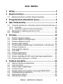 5
5
-
 6
6
-
 7
7
-
 8
8
-
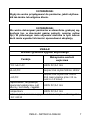 9
9
-
 10
10
-
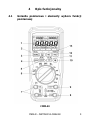 11
11
-
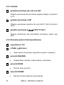 12
12
-
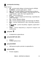 13
13
-
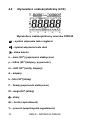 14
14
-
 15
15
-
 16
16
-
 17
17
-
 18
18
-
 19
19
-
 20
20
-
 21
21
-
 22
22
-
 23
23
-
 24
24
-
 25
25
-
 26
26
-
 27
27
-
 28
28
-
 29
29
-
 30
30
-
 31
31
-
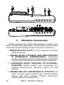 32
32
-
 33
33
-
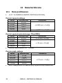 34
34
-
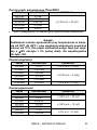 35
35
-
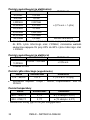 36
36
-
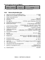 37
37
-
 38
38
-
 39
39
-
 40
40
-
 41
41
-
 42
42
-
 43
43
-
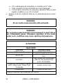 44
44
-
 45
45
-
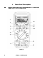 46
46
-
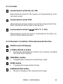 47
47
-
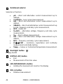 48
48
-
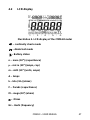 49
49
-
 50
50
-
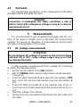 51
51
-
 52
52
-
 53
53
-
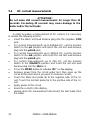 54
54
-
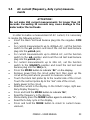 55
55
-
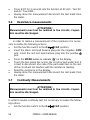 56
56
-
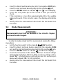 57
57
-
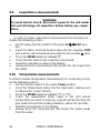 58
58
-
 59
59
-
 60
60
-
 61
61
-
 62
62
-
 63
63
-
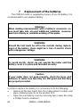 64
64
-
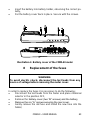 65
65
-
 66
66
-
 67
67
-
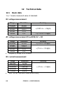 68
68
-
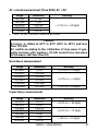 69
69
-
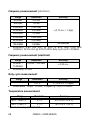 70
70
-
 71
71
-
 72
72
-
 73
73
-
 74
74
-
 75
75
-
 76
76
-
 77
77
-
 78
78
-
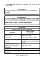 79
79
-
 80
80
-
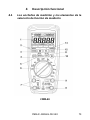 81
81
-
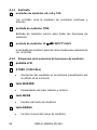 82
82
-
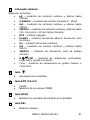 83
83
-
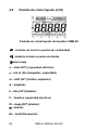 84
84
-
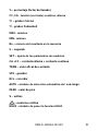 85
85
-
 86
86
-
 87
87
-
 88
88
-
 89
89
-
 90
90
-
 91
91
-
 92
92
-
 93
93
-
 94
94
-
 95
95
-
 96
96
-
 97
97
-
 98
98
-
 99
99
-
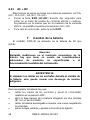 100
100
-
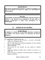 101
101
-
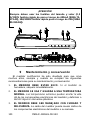 102
102
-
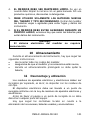 103
103
-
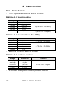 104
104
-
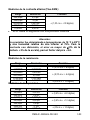 105
105
-
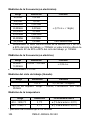 106
106
-
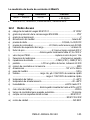 107
107
-
 108
108
-
 109
109
-
 110
110
-
 111
111
-
 112
112
-
 113
113
-
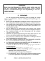 114
114
-
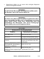 115
115
-
 116
116
-
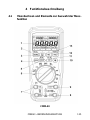 117
117
-
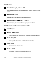 118
118
-
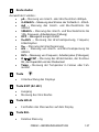 119
119
-
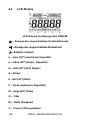 120
120
-
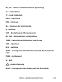 121
121
-
 122
122
-
 123
123
-
 124
124
-
 125
125
-
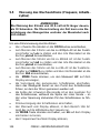 126
126
-
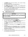 127
127
-
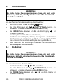 128
128
-
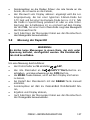 129
129
-
 130
130
-
 131
131
-
 132
132
-
 133
133
-
 134
134
-
 135
135
-
 136
136
-
 137
137
-
 138
138
-
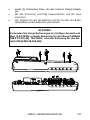 139
139
-
 140
140
-
 141
141
-
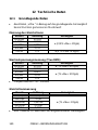 142
142
-
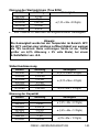 143
143
-
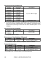 144
144
-
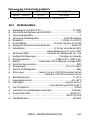 145
145
-
 146
146
-
 147
147
-
 148
148


en otros idiomas
- Deutsch: Sonel CMM-40 Benutzerhandbuch
- polski: Sonel CMM-40 Instrukcja obsługi
Artículos relacionados
-
Sonel CMM-60 Manual de usuario
-
Sonel CMM-10 Manual de usuario
-
-
-
-
-
-
-
-