
ES
FR
DE
EN
Operating instructions
Betriebsanleitung
Mode d'emploi
Manual de instrucciones
Resistance thermometers with digital display
Model TR75, battery powered
Widerstandsthermometer mit digitaler Anzeige
Typ TR75, Batteriebetrieb
Sondes à résistance avec achage numérique
Type TR75, fonctionnement sur pile
Termorresistencia con indicación digital
Modelo TR75, alimentación por batería
DiwiTherm
®
model TR75
DiwiTherm
®

2
WIKA operating instructions DiwiTherm
®
, model TR75
11325232.05 09/2016 EN/DE/FR/ES
ES
FR
DE
EN
Operating instructions model TR75 Page 3 - 24
Betriebsanleitung Typ TR75 Seite 25 - 44
Mode d'emploi type TR75 Page 45 - 66
Manual de instrucciones modelo TR75 Página 67 - 86
© 11/2010 WIKA Alexander Wiegand SE & Co. KG
All rights reserved. / Alle Rechte vorbehalten.
WIKA
®
is a registered trademark in various countries.
WIKA
®
ist eine geschützte Marke in verschiedenen Ländern.
Prior to starting any work, read the operating instructions!
Keep for later use!
Vor Beginn aller Arbeiten Betriebsanleitung lesen!
Zum späteren Gebrauch aufbewahren!
Lire le mode d'emploi avant de commencer toute opération !
A conserver pour une utilisation ultérieure !
¡Leer el manual de instrucciones antes de comenzar cualquier trabajo!
¡Guardar el manual para una eventual consulta!

11325232.05 09/2016 EN/DE/FR/ES
WIKA operating instructions DiwiTherm
®
, model TR75 3
EN
Contents
Contents
1. General information 4
2. Safety 5
3. Specications 7
4. Design and function 8
5. Transport, packaging and storage 15
6. Commissioning, operation 16
7. Maintenance and cleaning 19
8. Faults 20
9. Dismounting, return and disposal 21
Appendix: EU declaration of conformity 23
Declarations of conformity can be found online at www.wika.com.

11325232.05 09/2016 EN/DE/FR/ES
4 WIKA operating instructions DiwiTherm
®
, model TR75
EN
1. General information
■
The instrument described in the operating instructions has been designed and
manufactured using state-of-the-art technology. All components are subject to stringent
quality and environmental criteria during production. Our management systems are
certied to ISO 9001 and ISO 14001.
■
These operating instructions contain important information on handling the instrument.
Working safely requires that all safety instructions and work instructions are observed.
■
Observe the relevant local accident prevention regulations and general safety regulations
for the instrument's range of use.
■
The operating instructions are part of the product and must be kept in the immediate
vicinity of the instrument and readily accessible to skilled personnel at any time.
■
Skilled personnel must have carefully read and understood the operating instructions
prior to beginning any work.
■
The manufacturer's liability is void in the case of any damage caused by using the
product contrary to its intended use, non-compliance with these operating instructions,
assignment of insuciently qualied skilled personnel or unauthorised modications to
the instrument.
■
The general terms and conditions contained in the sales documentation shall apply.
■
Subject to technical modications.
■
Further information:
- Internet address: www.wika.de / www.wika.com
- Relevant data sheet: TE 60.75
- Application consultant:
Tel.: +49 9372 132-0
Fax: +49 9372 132-406
info@wika.com
Explanation of symbols
WARNING!
... indicates a potentially dangerous situation that can result in serious injury or
death, if not avoided.
CAUTION!
... indicates a potentially dangerous situation that can result in light injuries or
damage to equipment or the environment, if not avoided.
Information
... points out useful tips, recommendations and information for ecient and
trouble-free operation.
1. General information

11325232.05 09/2016 EN/DE/FR/ES
WIKA operating instructions DiwiTherm
®
, model TR75 5
EN
2. Safety
WARNING!
Before installation, commissioning and operation, ensure that the appropriate
thermometer has been selected in terms of measuring range, design and
specic measuring conditions.
Non-observance can result in serious injury and/or damage to the equipment.
Further important safety instructions can be found in the individual chapters of
these operating instructions.
2.1 Intended use
The DiwiTherm
®
thermometer is used mainly in the process industry to monitor process
temperatures.
The instrument has been designed and built solely for the intended use described here, and
may only be used accordingly.
The technical specications contained in these operating instructions must be observed.
Improper handling or operation of the instrument outside of its technical specications
requires the instrument to be taken out of service immediately and inspected by an
authorised WIKA service engineer.
If the instrument is transported from a cold into a warm environment, the formation of
condensation may result in instrument malfunction. Before putting it back into operation, wait
for the instrument temperature and the room temperature to equalise.
The manufacturer shall not be liable for claims of any type based on operation contrary to
the intended use.
2.2 Personnel qualication
WARNING!
Risk of injury should qualication be insucient!
Improper handling can result in considerable injury and damage to equipment.
■
The activities described in this operating instruction may only be carried out
by skilled personnel who have the qualications described below.
Skilled personnel
Skilled personnel are understood to be personnel who, based on their technical training,
knowledge of measurement and control technology and on their experience and knowledge
of country-specic regulations, current standards and directives, are capable of carrying out
the work described and independently recognising potential hazards.
Special operating conditions require further appropriate knowledge, e.g. of aggressive
media.
2. Safety

11325232.05 09/2016 EN/DE/FR/ES
6 WIKA operating instructions DiwiTherm
®
, model TR75
EN
2.3 Special hazards
WARNING!
For hazardous media such as oxygen, acetylene, ammable or toxic gases or
liquids, and refrigeration plants, compressors, etc., in addition to all standard
regulations, the appropriate existing codes or regulations must also be followed.
WARNING!
To ensure safe working on the instrument, the operating company must ensure
■
that suitable rst-aid equipment is available and aid is provided whenever
required.
■
that the operating personnel are regularly instructed in all topics regarding
work safety, rst aid and environmental protection and know the operating
instructions and, in particular, the safety instructions contained therein.
WARNING!
Residual media in dismounted instruments can result in a risk to persons, the
environment and equipment. Take sucient precautionary measures.
Do not use this instrument in safety or emergency stop devices. Incorrect use of
the instrument can result in injury.
Should a failure occur, aggressive media with extremely high temperature and
under high pressure or vacuum may be present at the instrument.
2.4 Labelling, safety marks
Product label
2. Safety
Model
Serial number
Year of manufacture
Application range
Before mounting and commissioning the instrument, ensure you read the
operating instructions!

11325232.05 09/2016 EN/DE/FR/ES
WIKA operating instructions DiwiTherm
®
, model TR75 7
EN
3. Specications
Resistance thermometer with digital display, model TR75
Measuring ranges -40.0 ... +199.9 °C / +200 ... +450 °C
with automatic measuring range changeover (autorange)
Display
■
Principle
■
Resolution
■
Accuracy
3 ½- digit LCD, 7-segment display, 21 mm high
0.1 K up to 199.9 °C; 1 K from 200 °C
0.5 % of the respective full-range value ±1 digit
Sensor Pt1000
Instrument variants
■
DiwiTherm
®
with sensor
for insertion
Sensor with connection cable
Max. working temperature 200 °C
Case for panel mounting, with panel mounting ange
■
DiwiTherm
®
for mounting
in a thermowell
Spring-loaded sensor
Screwed plug to thermowell
Case with neck tube
Option: Adjustable stem and dial (rotatable through 360° and tiltable
through 90°)
■
DiwiTherm
®
for mounting
on a pipe surface
Contact bulb for xing with tightening strap
Max. working temperature 200 °C
Case with neck tube
Option: Adjustable stem and dial (rotatable through 360° and tiltable
through 90°)
Case for panel mounting, with connection cable and panel
mounting ange
Power supply U
B
DC 3.6 V from 3.6 V lithium battery, AA size (Mignon), included in
delivery
1)
Operating time min. 10 years
Special features If the battery drops below 2.7 V, the display switches into “LO” mode
1) Not replaceable by the customer.
Case
Nominal size 100
Material Stainless steel
Bezel ring Bayonet ring
Window Instrument glass
Ingress protection IP65 per IEC/EN 60529
Weight approx. 1 kg (actual weight depends on design and possibly moun-
ted thermowell)
3. Specications

11325232.05 09/2016 EN/DE/FR/ES
8 WIKA operating instructions DiwiTherm
®
, model TR75
EN
Ambient conditions
Ambient and storage temperature -20 ... +60 °C
Vibration resistance (at sensor) 10 ... 500 Hz, 5 g, IEC/EN 60068-2-6
Shock resistance (at sensor) IEC/EN 60068-2-7
For further specications see WIKA data sheet TE 60.75 and the order documentation.
4. Design and function
4.1 Description
The DiwiTherm
®
model TR75 is the ideal combination of a digital display and a resistance
thermometer. This compact thermometer can be used in a wide range of applications and
works without an external power supply.
A wide variety of possibilities for the combination of insertion length, neck length, connection
to thermowell etc. are available for the thermometers, suitable for any thermowell and any
application.
Operation without thermowell is only recommended in certain applications.
Optionally, the DiwiTherm
®
model TR75 can be manufactured with a process connection for
measuring the temperature on a pipe's surface.
4.1.1 DiwiTherm
®
with sensor for insertion
Sensor
Material: stainless steel
Sensor length A ≤ 150 mm: Rigid sensor tube
The tubular design features a rigid construction to the metal sensor tip; therefore tubular
designs must not be bent. Internally, the measuring resistor is connected directly to an
insulated lead. Therefore tubular-design resistance thermometers can only be used up to the
temperatures specied for the lead (see operating temperatures).
Sensor length above 150 mm: Sheathed measuring cable (MI cable)
The junction between the metal part of the sensor and the connecting cable, when using MI
cable, is either crimped, rolled or potted, depending on the design. This area should not be
immersed within the process and must not be bent.
Compression ttings should not be attached to the transition. The type and dimensions of
the transition depend largely on the combination between input leads and metal sensor and
the sealing requirements.
The sensor diameter should be approx. 1 mm smaller than the bore diameter of the
thermowell or the blind bore, respectively.
3. Specications / 4. Design and function

11325232.05 09/2016 EN/DE/FR/ES
WIKA operating instructions DiwiTherm
®
, model TR75 9
EN
Gaps of more than 0.5 mm between thermowell and the sensor will have a negative eect on
the heat transfer, and they will result in unfavourable response behaviour of the thermometer.
Sensor lengths
Sensor diameter in mm Standard sensor lengths A (l
1
) in mm
6 50 100 150
8 - 100 150
Special lengths are possible.
Process connection
A compression tting enables simple, on-site adjustment to the required insertion length.
Compression tting
Material: stainless steel
G ¼ B male thread (not with Ø 8 mm sensors) or G ½ B
Delivery also possible without process connection.
Cable
Silicone, shielded, application range -40 ... +200 °C with EMC cable gland
Cable length to customer specication.
The sensor sleeve and case are connected by the cable shielding. Earthing on both ends
can lead to potential losses and indication inaccuracy.
3165575.06
Panel mounting
ange
DiwiTherm
®
battery operation, model TR75 with sensor for insertion, rear cable entry,
with panel mounting ange
Legend:
Ø d Sensor diameter
A Insertion length
W Cable length
Tubular design
Sheathed cable design
MI cable ∅ = sleeve ∅
4. Design and function

11325232.05 09/2016 EN/DE/FR/ES
10 WIKA operating instructions DiwiTherm
®
, model TR75
EN
4.1.2 DiwiTherm
®
for mounting in a thermowell
Sensor
Material: stainless steel
The sensor is made from vibration-resistant, sheathed cable (MI cable).
The sensor diameter should be approx. 1 mm smaller than the bore diameter of the
thermowell. Gaps of more than 0.5 mm between thermowell and the sensor will have a
negative eect on the heat transfer, and they will result in unfavourable response behaviour
of the thermometer.
When tting the measuring insert into a thermowell, it is very important to determine the
correct insertion length (= thermowell length for bottom thicknesses of ≤ 5.5 mm). In order to
ensure that the sensor is rmly pressed down onto the bottom of the thermowell, the sensor
must be spring-loaded (spring travel: max 10 mm).
Process connection (standard process connection)
Material: stainless steel
Threaded connection: G ½ B
M14 x 1.5
M18 x 1.5
½ NPT
Union nut: G ½ B
Male nut: G ½ B
Neck tube
Material: stainless steel
Neck tube diameter: 12 mm
Standard neck length: 150 mm
others on request
(minimum neck length: 30 mm)
Sensor lengths
Sensor Ø
in mm
Standard insertion lengths A (l
1
) in mm
3 110 140 145 170 200 205 230 245 260 294 305 345 350 395 410 445 545
6 - - - 170 200 205 230 245 260 295 305 345 350 395 410 445 545
8 - - - - 200 205 230 245 260 295 305 345 350 395 410 445 545
Special lengths are possible.
4. Design and function

11325232.05 09/2016 EN/DE/FR/ES
WIKA operating instructions DiwiTherm
®
, model TR75 11
EN
4. Design and function
Thread
Thread
Thread
Thread
Thread
Fixed threaded
connections / threads
Connection to thermowell (with neck tube)
Compression tting
(xing to neck tube)
Union nut
Neck tube
smooth
3172503.08
Legend:
Ø d Sensor diameter
A (l
1
) Insertion length
(with parallel threads)
A (U
2
) Insertion length
(with tapered threads)
N(M
H
) Neck length
Connection to thermowell
Male nut for
sealing case
Double nipple version
“nipple-union-nipple”
neck tube
Female
thread
M24 x 1.5
Thread Thread Thread
11363533.04

11325232.05 09/2016 EN/DE/FR/ES
12 WIKA operating instructions DiwiTherm
®
, model TR75
EN
3161218.06 3161374.06
Ø 8 mm variant
DiwiTherm
®
model TR75 for mounting in a thermowell, with neck tube
Connection from housing to neck tube: xed, lower mount
Thread
Ø 8 mm variant
Thread
DiwiTherm
®
model TR75 for mounting in a thermowell, with neck tube
Connection from housing to neck tube: adjustable stem and dial,
rear mount, centric
4. Design and function

11325232.05 09/2016 EN/DE/FR/ES
WIKA operating instructions DiwiTherm
®
, model TR75 13
EN
4.1.3 DiwiTherm
®
for mounting on a pipe surface
Contact bulb
Material: stainless steel
Mounting tube: 120 mm
Fixing with a tightening strap (not included in delivery)
Cable
Silicone, shielded, application range -50 ... +200 °C
Cable length to user specications
The sensor sleeve and case are connected by the cable shielding. Earthing on both ends
can lead to potential losses and indication inaccuracy.
The specied accuracy can only be guaranteed up to a maximum cable length of 15 m. With
longer cable lengths, the accuracy can deviate sharply.
3157559.05
DiwiTherm
®
model TR75 for mounting on a pipe surface, rear cable output, with panel
mounting ange
Panel mounting
ange
4. Design and function

11325232.05 09/2016 EN/DE/FR/ES
14 WIKA operating instructions DiwiTherm
®
, model TR75
EN
Neck tube
Material: stainless steel
Neck tube diameter: 12 mm
Standard neck length: 150 mm, others on request (minimum neck length: 100 mm)
3157541.04
DiwiTherm
®
model TR75 for mounting on a pipe surface, with neck tube
Connection from housing to neck tube: xed, lower mount
11144807.04
DiwiTherm
®
model TR75 for mounting on a pipe surface, with neck tube
Connection from housing to neck tube: adjustable stem and dial,
rear mount, centric
4. Design and function

11325232.05 09/2016 EN/DE/FR/ES
WIKA operating instructions DiwiTherm
®
, model TR75 15
EN
4.2 Scope of delivery
Cross-check scope of delivery with delivery note.
5. Transport, packaging and storage
5.1 Transport
Check the instrument for any damage that may have been caused by transport.
Obvious damage must be reported immediately.
5.2 Packaging
Do not remove packaging until just before mounting.
Keep the packaging as it will provide optimum protection during transport (e.g. change in
installation site, sending for repair).
Examine the packaging material carefully so that no accessories that might be packed within
it are lost.
5.3 Storage
Permissible conditions at the place of storage:
■
Storage temperature: -20 ... +60 °C
■
Humidity: 35 ... 85 % relative humidity (no condensation)
Avoid exposure to the following factors:
■
Direct sunlight or proximity to hot objects
■
Mechanical vibration, mechanical shock (putting it down hard)
■
Soot, vapour, dust and corrosive gases
■
Potentially explosive environments, ammable atmospheres
Store the instrument in its original packaging in a location that fulls the conditions listed
above. If the original packaging is not available, pack and store the instrument as described
below:
1. Wrap the instrument in an antistatic plastic lm.
2. Place the instrument along with shock-absorbent material in the packaging.
3. If stored for a prolonged period of time (more than 30 days), place a bag containing a
desiccant inside the packaging.
WARNING!
Before storing the instrument (following operation), remove any residual media.
This is of particular importance if the medium is hazardous to health, e.g. caustic,
toxic, carcinogenic, radioactive, etc.
4. Design and function / 5. Transport, packaging and storage

11325232.05 09/2016 EN/DE/FR/ES
16 WIKA operating instructions DiwiTherm
®
, model TR75
EN
Typical mounting situation with contact bulb
■
Mounting on pipes
The geometry of the contact bulb has been
designed for pipes with external diameters
between 20 and 160 mm. For xing the
contact bulb to the pipe, pipe clamps are
sucient. The contact bulb should have
direct metallic contact with the measuring
point and have rm contact with the surface
of the pipe. Where temperatures under
200 °C are expected, a heat conductive
paste can be used to optimise the heat
transmission between contact bulb and pipe.
Insulation must be applied at the mounting
point to avoid error due to heat loss. This
insulation must have sucient temperature
resistance and is not included in the scope
of delivery.
Pipe clamp mounting
Lagging *
* Lagging mandatory!
Measuring
insert
Thermowell
6. Commissioning, operation
DiwiTherms
®
must only be operated with an additional thermowell.
Exception: Axial cable outlet (for panel mounting) or version with contact bulb.
Typical mounting situation with thermowell
6. Commissioning, operation

11325232.05 09/2016 EN/DE/FR/ES
WIKA operating instructions DiwiTherm
®
, model TR75 17
EN
■
Mounting on tanks
The geometry of the contact bulb has been
designed for vessels with an external radius
up to 160 mm. If the mounting point of the
skin mounting contact bulb on the tank has
an external radius greater than 160 mm,
we recommend the use of an intermediate
piece designed for the respective tank
diameter, made of a material with good
thermal conductivity. The contact bulb can
be fastened to the tank by means of an angle
bracket with clamping screws, or any similar
method. The contact bulb should have direct
metallic contact with the measuring point and
have rm contact with the surface of the tank.
A heat conductive paste can be used to optimise the heat transmission between contact
bulb and vessel, if temperatures under 200 °C are expected. Insulation must be applied
at the mounting point to avoid error due to heat loss. This insulation must have sucient
temperature resistance and is not included in the scope of delivery.
When mounting a rotatable and inclinable DiwiTherm
®
thermometer, the specic
instructions must be followed. In order to set the indicator to the desired position, the
following steps must be taken:
1. The lock nut or union nut must be loosened at the process connection.
Angle bracket mounting
Lagging *
* Lagging mandatory!
2. The hexagon bolts and slotted screws at the swivel joint must be loosened.
loosening
Make sure to loosen the screws on
the opposite side as well!
Installation with
open-ended spanner
6. Commissioning, operation
3. Position the indicator as required, tighten the hexagon bolts and slotted screws, and nally
tighten the lock nut or union nut rmly.

11325232.05 09/2016 EN/DE/FR/ES
18 WIKA operating instructions DiwiTherm
®
, model TR75
EN
Observe the following points during sensor installation:
■
If possible, the entire length of the sensor should be exposed to the temperature being
measured.
■
In pipelines or at other measuring points, the temperature sensor should be directed as
far towards the ow as possible.
■
When using thermowells, ll a thermal contact medium in order to reduce the heat
transfer resistance between the outer wall of the sensor and the inner wall of the
thermowell if possible. The working temperature of the heat conductive paste is
-40 ... +200 °C.
WARNING!
Do not use any heat transfer oil!
6.1 Parallel threads
If the thermometer connecting head, neck tube, thermowell or process connection are
connected with parallel threads (e.g. G ½, M20 x 1.5 ...), these threads must be secured
using seals which prevent liquids from penetrating into the thermometer.
As standard, WIKA uses copper prole seals for the connection between the neck tube
and the thermowell, and at paper seals for the connection of the connection head and the
extension neck or thermowell.
If the thermometer and the thermowell are already connected, the seals will already be
mounted. The plant operator must check whether the seals are suitable for the operating
conditions and must replace them, if necessary, with suitable seals.
For thermometers without a thermowell, and/or where these are delivered separately, the
seals are not included and must be ordered separately.
Tighten the threads by hand when carrying out the nal assembly on the plant. This will
correspond to the delivery status of the premounted components. The nal tightening torque
should be applied using a spanner (half rotation).
The seals must be replaced after dismantling!
The seals can be ordered from WIKA, indicating the WIKA order number and/or
the designation (see table).
6. Commissioning, operation

11325232.05 09/2016 EN/DE/FR/ES
WIKA operating instructions DiwiTherm
®
, model TR75 19
EN
WIKA
Order no.
Designation Suitable for threads
11349981 per DIN 7603 Form C 14 x 18 x 2 -CuFA G ¼, M14 x 1.5
11349990 per DIN 7603 Form C 18 x 22 x 2 -CuFA M18 x 1.5, G ⅜
11350008 per DIN 7603 Form C 21 x 26 x 2 -CuFA G ½, M20 x 1.5
11350016 per DIN 7603 Form C 27 x 32 x 2.5 -CuFA G ¾, M27 x 2
11367416 per DIN 7603 Form C 20 x 24 x 2 -CuFA M20 x 1.5
1248278 per DIN 7603 D21.2 x D25.9 x 1.5 -Al G ½, M20 x 1.5
3153134 per DIN 7603 Form C D14.2 x D17.9 x 2 -StFA G ¼, M14 x 1.5
3361485 per DIN 7603 Form C D33.3 x D38.9 x 2.5 -StFA G 1
11355352 D15 x D21 x 3 -NP-Univ M24 x 1.5
1605933 D15 x D21 x 1 -NP-Univ M24 x 1.5
Legend:
CuFA = Copper, max. 45 HB
a
; lled with asbestos-free sealing material
Al = Aluminium Al99; F11, 32 to 45 HB
b
StFA = Soft iron, 80 to 95 HB
a
; lled with asbestos-free sealing material
6.2 Tapered threads (NPT)
It should be checked whether it may be necessary to seal them additionally with PTFE tape
or hemp. The threads must be lubricated with a suitable lubricant before tting.
Tighten the threads by hand when carrying out the nal assembly on the plant. This will
correspond to the delivery status of the premounted components. The nal tightening and
sealing must be made with a spanner (1.5 to 3 rotations).
7. Maintenance and cleaning
7.1 Maintenance
The DiwiTherm
®
thermometer is maintenance-free.
The indicator should be checked once or twice every year.
To do this, the instrument must be disconnected from the process and checked using a
temperature calibrator.
DiwiTherm
®
model TR75: battery powered (at least 10 years service life)
The battery is not replaceable!
Repairs must only be carried out by the manufacturer.
6. Commissioning, operation / 7. Maintenance and cleaning

11325232.05 09/2016 EN/DE/FR/ES
20 WIKA operating instructions DiwiTherm
®
, model TR75
EN
7.2 Cleaning
CAUTION!
■
Before cleaning, correctly disconnect the instrument from the pressure supply,
switch it o and disconnect it from the mains.
■
Clean the instrument with a moist cloth (soap water).
■
Electrical connections must not come into contact with moisture.
■
Wash or clean the dismounted instrument before returning it, in order to
protect personnel and the environment from exposure to residual media.
■
Residual media in dismounted instruments can result in a risk to persons, the
environment and equipment.
Take sucient precautionary measures.
For information on returning the instrument see chapter 9.2 “Return”.
8. Faults
Faults Causes Measures
The battery has less than
2.7 V
Error message
The battery has less than 2.7 V Contact the manufacturer
No signal/ line break Mechanical load too high or
overtemperature
Replacement of the sensor
or the measuring insert with a
suitable version
Display of measured value
jumps
Cable break in connecting
cable or loose contact caused
by mechanical overload
Replacement of the sensor or
measuring insert with a suitable
design, for example a thicker
conductor cross-section
Erroneous measured values
and response times too long
Wrong mounting geometry, e.g.
mounting depth too deep or
heat dissipation too high
The temperature-sensitive area
of the sensor must be inside
the medium, and surfaces
measurements must be
ungrounded
Erroneous measured values
and response times too long
Deposits on the sensor or
thermowell
Remove deposits
Corrosion Composition of the medium
not as expected or modied
or wrong thermowell material
selected
Analyse medium and then
select a more-suitable material
or replace thermowell regularly
7. Maintenance and cleaning / 8. Faults

11325232.05 09/2016 EN/DE/FR/ES
WIKA operating instructions DiwiTherm
®
, model TR75 21
EN
Faults Causes Measures
Moisture or media uid in the
housing
No thermowell used (the cable
version is not suitable). No or
faulty sealing used between
neck tube and thermowell.
Contact manufacturer, send
the instrument back (For
information on returning, see
chapter 9.2 “Return”).
Too high humidity and strong
temperature changes.
Check ambient conditions.
CAUTION!
If faults cannot be eliminated by means of the measures listed above, shut
down the instrument immediately, and ensure that pressure and/or signal are no
longer present, and secure the instrument from being put back into operation
inadvertently.
In this case, contact the manufacturer.
If a return is needed, follow the instructions given in chapter 9.2 “Return”.
9. Dismounting, return and disposal
WARNING!
Residual media in dismounted instruments can result in a risk to persons, the
environment and equipment.
Sucient precautionary measures must be taken.
9.1 Disassembly
WARNING!
Risk of burns!
Let the instrument cool down suciently before dismounting it!
During dismounting there is a risk of dangerously hot pressure media escaping.
Only disconnect the thermometer once the system has been depressurised!
9.2 Return
WARNING!
Strictly observe the following when shipping the instrument:
All instruments delivered to WIKA must be free from any kind of hazardous
substances (acids, bases, solutions, etc.).
When returning the instrument, use the original packaging or a suitable transport package.
8. Faults / 9. Dismounting, return and disposal

11325232.05 09/2016 EN/DE/FR/ES
22 WIKA operating instructions DiwiTherm
®
, model TR75
EN
To avoid damage:
1. Wrap the instrument in an antistatic plastic lm.
2. Place the instrument, along with shock-absorbent material, in the packaging.
Place shock-absorbent material evenly on all sides of the transport packaging.
3. If possible, place a bag containing a desiccant inside the packaging.
4. Label the shipment as carriage of a highly sensitive measuring instrument.
Information on returns can be found under the heading “Service” on our local
website.
9.3 Disposal
Incorrect disposal can put the environment at risk.
Dispose of instrument components and packaging materials in an environmentally
compatible way and in accordance with the country-specic waste disposal regulations.
9. Dismounting, return and disposal

11325232.05 09/2016 EN/DE/FR/ES
WIKA operating instructions DiwiTherm
®
, model TR75 23
EN
Appendix: EU declaration of conformity

11325232.05 09/2016 EN/DE/FR/ES
24 WIKA operating instructions DiwiTherm
®
, model TR75
EN

11325232.05 09/2016 EN/DE/FR/ES
WIKA Betriebsanleitung DiwiTherm
®
, Typ TR75 25
DE
Inhalt
Inhalt
1. Allgemeines 26
2. Sicherheit 27
3. Technische Daten 29
4. Aufbau und Funktion 30
5. Transport, Verpackung und Lagerung 37
6. Inbetriebnahme, Betrieb 38
7. Wartung und Reinigung 41
8. Störungen 42
9. Demontage, Rücksendung und Entsorgung 43
Anlage: EU-Konformitätserklärung 23
Konformitätserklärungen nden Sie online unter www.wika.de.

11325232.05 09/2016 EN/DE/FR/ES
26 WIKA Betriebsanleitung DiwiTherm
®
, Typ TR75
DE
1. Allgemeines
■
Das in der Betriebsanleitung beschriebene Gerät wird nach dem aktuellen Stand der
Technik konstruiert und gefertigt. Alle Komponenten unterliegen während der Ferti-
gung strengen Qualitäts- und Umweltkriterien. Unsere Managementsysteme sind nach
ISO 9001 und ISO 14001 zertiziert.
■
Diese Betriebsanleitung gibt wichtige Hinweise zum Umgang mit dem Gerät. Vorausset-
zung für sicheres Arbeiten ist die Einhaltung aller angegebenen Sicherheitshinweise und
Handlungsanweisungen.
■
Die für den Einsatzbereich des Gerätes geltenden örtlichen Unfallverhütungsvorschriften
und allgemeinen Sicherheitsbestimmungen einhalten.
■
Die Betriebsanleitung ist Produktbestandteil und muss in unmittelbarer Nähe des Gerätes
für das Fachpersonal jederzeit zugänglich aufbewahrt werden.
■
Das Fachpersonal muss die Betriebsanleitung vor Beginn aller Arbeiten sorgfältig durch-
gelesen und verstanden haben.
■
Die Haftung des Herstellers erlischt bei Schäden durch bestimmungswidrige Verwen-
dung, Nichtbeachten dieser Betriebsanleitung, Einsatz ungenügend qualizierten
Fachpersonals sowie eigenmächtiger Veränderung am Gerät.
■
Es gelten die allgemeinen Geschäftsbedingungen in den Verkaufsunterlagen.
■
Technische Änderungen vorbehalten.
■
Weitere Informationen:
- Internet-Adresse: www.wika.de / www.wika.com
- zugehöriges Datenblatt: TE 60.75
- Anwendungsberater:
Tel.: +49 9372 132-0
Fax: +49 9372 132-406
info@wika.de
Symbolerklärung
WARNUNG!
… weist auf eine möglicherweise gefährliche Situation hin, die zum Tod oder zu
schweren Verletzungen führen kann, wenn sie nicht gemieden wird.
VORSICHT!
… weist auf eine möglicherweise gefährliche Situation hin, die zu geringfügigen
oder leichten Verletzungen bzw. Sach- und Umweltschäden führen kann, wenn
sie nicht gemieden wird.
Information
… hebt nützliche Tipps und Empfehlungen sowie Informationen für einen ezi-
enten und störungsfreien Betrieb hervor.
1. Allgemeines

11325232.05 09/2016 EN/DE/FR/ES
WIKA Betriebsanleitung DiwiTherm
®
, Typ TR75 27
DE
2. Sicherheit
WARNUNG!
Vor Montage, Inbetriebnahme und Betrieb sicherstellen, dass das richtige
Thermometer hinsichtlich Messbereich, Ausführung und spezischen Messbe-
dingungen ausgewählt wurde.
Bei Nichtbeachten können schwere Körperverletzungen und/oder Sachschäden
auftreten.
Weitere wichtige Sicherheitshinweise benden sich in den einzelnen Kapiteln
dieser Betriebsanleitung.
2.1 Bestimmungsgemäße Verwendung
Das DiwiTherm
®
-Thermometer wird hauptsächlich in der Prozessindustrie eingesetzt, um
die Temperatur des Prozesses zu überwachen.
Das Gerät ist ausschließlich für den hier beschriebenen bestimmungsgemäßen Verwen-
dungszweck konzipiert und konstruiert und darf nur dementsprechend verwendet werden.
Die technischen Spezikationen in dieser Betriebsanleitung sind einzuhalten. Eine unsach-
gemäße Handhabung oder ein Betreiben des Gerätes außerhalb der technischen Spezi-
kationen macht die sofortige Stilllegung und Überprüfung durch einen autorisierten WIKA-
Servicemitarbeiter erforderlich.
Wird das Gerät von einer kalten in eine warme Umgebung transportiert, so kann durch
Kondensatbildung eine Störung der Gerätefunktion eintreten. Vor einer erneuten Inbetrieb-
nahme die Angleichung der Gerätetemperatur an die Raumtemperatur abwarten.
Ansprüche jeglicher Art aufgrund von nicht bestimmungsgemäßer Verwendung sind ausge-
schlossen.
2.2 Personalqualikation
WARNUNG!
Verletzungsgefahr bei unzureichender Qualikation!
Unsachgemäßer Umgang kann zu erheblichen Personen- und Sachschäden
führen.
■
Die in dieser Betriebsanleitung beschriebenen Tätigkeiten nur durch
Fachpersonal nachfolgend beschriebener Qualikation durchführen lassen.
Fachpersonal
Das Fachpersonal ist aufgrund seiner fachlichen Ausbildung, seiner Kenntnisse der Mess-
und Regelungstechnik und seiner Erfahrungen sowie Kenntnis der landesspezischen
Vorschriften, geltenden Normen und Richtlinien in der Lage, die beschriebenen Arbeiten
auszuführen und mögliche Gefahren selbstständig zu erkennen.
Spezielle Einsatzbedingungen verlangen weiteres entsprechendes Wissen, z. B. über agres-
sive Medien.
2. Sicherheit

11325232.05 09/2016 EN/DE/FR/ES
28 WIKA Betriebsanleitung DiwiTherm
®
, Typ TR75
DE
2.3 Besondere Gefahren
WARNUNG!
Bei gefährlichen Messstoen wie z. B. Sauersto, Acetylen, brennbaren oder
giftigen Stoen, sowie bei Kälteanlagen, Kompressoren etc. müssen über die
gesamten allgemeinen Regeln hinaus die einschlägigen Vorschriften beachtet
werden.
WARNUNG!
Für ein sicheres Arbeiten am Gerät muss der Betreiber sicherstellen,
■
dass eine entsprechende Erste-Hilfe-Ausrüstung vorhanden ist und bei
Bedarf jederzeit Hilfe zur Stelle ist.
■
dass das Bedienpersonal regelmäßig in allen zutreenden Fragen von
Arbeitssicherheit, Erste-Hilfe und Umweltschutz unterwiesen wird, sowie
die Betriebsanleitung und insbesondere die darin enthaltenen Sicher-
heitshinweise kennt.
WARNUNG!
Messstoreste in ausgebauten Geräten können zur Gefährdung von Personen,
Umwelt und Einrichtung führen. Ausreichende Vorsichtsmaßnahmen ergreifen.
Dieses Gerät nicht in Sicherheits- oder in Not-Aus-Einrichtungen benutzen.
Fehlerhafte Anwendungen des Gerätes können zu Verletzungen führen.
Am Gerät können im Fehlerfall aggressive Medien mit extremer Temperatur und
unter hohem Druck oder Vakuum anliegen.
2.4 Beschilderung, Sicherheitskennzeichnungen
Typenschild
2. Sicherheit
Typ
Seriennummer
Herstellungsjahr
Anwendungsbereich
Vor Montage und Inbetriebnahme des Gerätes unbedingt die Betriebsan-
leitung lesen!

11325232.05 09/2016 EN/DE/FR/ES
WIKA Betriebsanleitung DiwiTherm
®
, Typ TR75 29
DE
3. Technische Daten
Widerstandsthermometer mit digitaler Anzeige, Typ TR75
Messbereiche -40,0 ... +199,9 °C / +200 ... +450 °C
mit automatischer Messbereichsumschaltung (Autorange)
Anzeige
■
Prinzip
■
Auösung
■
Genauigkeit
3 ½-stellig LCD, 7-Segment-Anzeige, 21 mm hoch
0,1 K bis 199,9 °C; 1 K ab 200 °C
0,5 % vom jeweiligen Bereichsendwert ±1 Digit
Sensor Pt1000
Gerätevarianten
■
DiwiTherm
®
mit Fühler
zum Einstecken
Fühler mit Anschlusskabel
Einsatztemperatur max. 200 °C
Gehäuse für Schalttafeleinbau, mit Befestigungsrand vorn
■
DiwiTherm
®
zum Einbau
in ein Schutzrohr
Fühler gefedert
Einschraubzapfen zum Schutzrohr
Gehäuse mit Halsrohr
Option: Gehäuse dreh- und schwenkbar (um 360° drehbar und um
90° schwenkbar)
■
DiwiTherm
®
zur Montage
an einer Rohroberäche
Anliegefühler zur Befestigung mittels Spannband
Einsatztemperatur max. 200 °C
Gehäuse mit Halsrohr
Option: Gehäuse dreh- und schwenkbar (um 360° drehbar und um
90° schwenkbar)
Gehäuse für Schalttafeleinbau, mit Anschlusskabel und
Befestigungsrand vorn
Hilfsenergie U
B
DC 3,6 V aus Lithium-Batterie 3,6 V, Größe AA (Mignon), gehört
zum Lieferumfang
1)
Betriebsdauer min. 10 Jahre
Besonderheiten Wenn die Batterie 2,7 V unterschreitet schaltet die Anzeige in „LO“
Betrieb
1) Nicht durch den Kunden austauschbar.
Gehäuse
Nenngröße 100
Werksto CrNi-Stahl
Ring Bajonettring
Sichtscheibe Instrumentenachglas
Schutzart IP65 nach IEC/EN 60529
Gewicht ca. 1 kg (tatsächliches Gewicht abhängig von Bauform und evtl.
montiertem Schutzrohr)
3. Technische Daten

11325232.05 09/2016 EN/DE/FR/ES
30 WIKA Betriebsanleitung DiwiTherm
®
, Typ TR75
DE
Umgebungsbedingungen
Umgebungs- und Lagertemperatur -20 ... +60 °C
Vibrationsbeständigkeit (am Fühler) 10 ... 500 Hz, 5 g, IEC/EN 60068-2-6
Schockfestigkeit (am Fühler) IEC/EN 60068-2-7
Weitere technische Daten siehe WIKA-Datenblatt TE 60.75 und Bestellunterlagen.
4. Aufbau und Funktion
4.1 Beschreibung
Das DiwiTherm
®
Typ TR75 ist die ideale Kombination aus einer Digitalanzeige und einem
Widerstandsthermometer. Dieses kompakte Thermometer kann vielseitig eingesetzt werden
und arbeitet ohne externe Hilfsenergie.
Vielfältige Kombinationsmöglichkeiten von Einbaulänge, Halslänge, Anschluss zum Schutz-
rohr etc. führen zu Thermometern, passend für jede Schutzrohrdimension und jede Anwen-
dung.
Ein Betrieb ohne Schutzrohr ist nur in speziellen Fällen zweckmäßig.
Optional kann das DiwiTherm
®
Typ TR75 mit einem Prozessanschluss zur Messung der
Temperatur an einer Rohroberäche gefertigt werden.
4.1.1 DiwiTherm
®
mit Fühler zum Einstecken
Fühler
Werksto: CrNi-Stahl
Fühlerlänge A ≤ 150 mm: Starres Fühlerrohr
Der Rohraufbau zeichnet sich durch einen starren Aufbau der metallischen Sensorspitze
aus, daher dürfen Rohraufbauten nicht gebogen werden. Im Inneren ist der Messwiderstand
direkt an eine isolierte Zuleitung kontaktiert. Daher können Widerstandsthermometer im
Rohraufbau nur bis zu Temperaturen eingesetzt werden, für welche die Zuleitung speziziert
ist (siehe Einsatztemperaturen).
Fühlerlänge ab 150 mm: Mantelmessleitung (MI-Leitung)
Der Übergang zwischen metallischem Teil des Fühlers und Anschlussleitung ist bei der
Verwendung von MI-Leitung je nach Ausführung gecrimpt, gerollt oder vergossen. Dieser
Bereich sollte nicht in den Prozess eingetaucht werden und darf nicht geknickt werden.
Auf dieser Übergangshülse sollte keine Klemmverschraubung befestigt werden. Ausführung
und Dimension der Übergangsstelle hängen stark von der Kombination zwischen Zuleitung
und metallischen Sensor und den Anforderungen an die Dichtigkeit ab.
Der Fühlerdurchmesser soll ca. 1 mm kleiner sein als der Bohrungsdurchmesser des
Schutzrohres bzw. der Sacklochbohrung.
3. Technische Daten / 4. Aufbau und Funktion

11325232.05 09/2016 EN/DE/FR/ES
WIKA Betriebsanleitung DiwiTherm
®
, Typ TR75 31
DE
Spaltbreiten größer als 0,5 mm zwischen Schutzrohr und Fühler wirken sich negativ auf den
Wärmeübergang aus und haben ein ungünstiges Ansprechverhalten des Thermometers zur
Folge.
Fühlerlängen
Fühlerdurchmesser in mm Standard-Fühlerlängen A (l
1
) in mm
6 50 100 150
8 - 100 150
Sonderlängen sind möglich.
Prozessanschluss
Eine Klemmverschraubung erlaubt an der Montagestelle das einfache Anpassen auf die
gewünschte Einbaulänge.
Klemmverschraubung
Werksto: CrNi-Stahl
Außengewinde G ¼ B (nicht bei Fühlerdurchmesser 8 mm) oder G ½ B
Lieferung auch ohne Prozessanschluss möglich.
Kabel
Silikon, geschirmt, Anwendungsbereich -40 ... +200 °C mit EMV-Kabelverschraubung
Kabellänge nach Kundenspezikation.
Sensorhülse und Gehäuse sind durch die Schirmung des Kabels verbunden. Beidseitige
Erdung kann zu Potentialverschleppung und Anzeigeungenauigkeit führen.
4. Aufbau und Funktion
3165575.06
Befestigungsrand
vorn
DiwiTherm
®
Batteriebetrieb, Typ TR75 mit Fühler zum Einstecken, rückseitiger Kabelabgang,
mit Befestigungsrand vorn für Schalttafeleinbau
Legende:
Ø d Fühlerdurchmesser
A Einbaulänge
W Kabellänge
Rohraufbau
Mantelleitungsaufbau
MI-Leiter-∅ = Hülsen-∅

11325232.05 09/2016 EN/DE/FR/ES
32 WIKA Betriebsanleitung DiwiTherm
®
, Typ TR75
DE
4. Aufbau und Funktion
4.1.2 DiwiTherm
®
zum Einbau in ein Schutzrohr
Fühler
Werksto: CrNi-Stahl
Der Fühler ist aus vibrationsunempndlicher Mantelleitung (MI-Leitung) gefertigt.
Der Fühlerdurchmesser soll ca. 1 mm kleiner sein als der Bohrungsdurchmesser des
Schutzrohres. Spaltbreiten größer als 0,5 mm zwischen Schutzrohr und Fühler wirken sich
negativ auf den Wärmeübergang aus und haben ein ungünstiges Ansprechverhalten des
Thermometers zur Folge.
Wichtig beim Einbau in ein Schutzrohr ist die Ermittlung der korrekten Einbaulänge
(= Schutzrohrlänge bei Bodenstärken ≤ 5,5 mm). Zu beachten ist dabei, dass der Fühler
gefedert ist (Federweg: max. 10 mm), um eine Anpressung auf den Schutzrohrboden zu
gewährleisten.
Prozessanschluss (Standardprozessanschluss)
Werksto: CrNi-Stahl
Einschraubzapfen: G ½ B
M14 x 1,5
M18 x 1,5
½ NPT
Überwurfmutter: G ½ B
Druckschraube: G ½ B
Halsrohr
Werksto: CrNi-Stahl
Halsrohrdurchmesser: 12 mm
Standard Halslänge: 150 mm
andere auf Anfrage
(minimale Halslänge: 30 mm)
Fühlerlängen
Fühler-Ø
in mm
Standard-Einbaulängen A (l
1
) in mm
3 110 140 145 170 200 205 230 245 260 294 305 345 350 395 410 445 545
6 - - - 170 200 205 230 245 260 295 305 345 350 395 410 445 545
8 - - - - 200 205 230 245 260 295 305 345 350 395 410 445 545
Sonderlängen sind möglich.

11325232.05 09/2016 EN/DE/FR/ES
WIKA Betriebsanleitung DiwiTherm
®
, Typ TR75 33
DE
4. Aufbau und Funktion
3172503.08
Anschluss zum Schutzrohr (mit Halsrohr)
Gewinde
Gewinde
Gewinde
Gewinde
Feste Verschraubung /
Gewinde
Halsrohr
glatt
Klemmverschraubung
(Befestigung auf Halsrohr)
Überwurfmutter
Legende:
Ø d Fühlerdurchmesser
A (l
1
) Einbaulänge
(bei zylindrischen Gewinden)
A (U
2
) Einbaulänge
(bei kegeligen Gewinden)
N(M
H
) Halslänge
Anschluss zum Schutzrohr
Druckschraube
zur Abdichtung
zum Gehäuse
Doppelnippel
Innen-
gewinde
M24 x 1,5
11363533.04
Gewinde
teilbares Halsrohr
Gewinde
Gewinde

11325232.05 09/2016 EN/DE/FR/ES
34 WIKA Betriebsanleitung DiwiTherm
®
, Typ TR75
DE
3161218.06 3161374.06
Variante Ø 8 mm
DiwiTherm
®
Typ TR75 zum Einbau in ein Schutzrohr, mit Halsrohr
Anschluss vom Gehäuse zum Halsrohr: fest, radial unten
Gewinde
Variante Ø 8 mm
Gewinde
DiwiTherm
®
Typ TR75 zum Einbau in ein Schutzrohr, mit Halsrohr
Anschluss vom Gehäuse zum Halsrohr: dreh- und schwenkbar,
rückseitig zentrisch
4. Aufbau und Funktion

11325232.05 09/2016 EN/DE/FR/ES
WIKA Betriebsanleitung DiwiTherm
®
, Typ TR75 35
DE
4.1.3 DiwiTherm
®
zur Montage an einer Rohroberäche
Anliegefühler
Werksto: CrNi-Stahl
Befestigungsrohr: 120 mm
Befestigung mittels Spannband (nicht im Lieferumfang)
Kabel
Silikon, geschirmt, Anwendungsbereich -50 ... +200 °C
Kabellänge nach Kundenspezikation
Sensorhülse und Gehäuse sind durch die Schirmung des Kabels verbunden. Beidseitige
Erdung kann zu Potentialverschleppung und Anzeigeungenauigkeit führen.
Die angegebene Genauigkeit kann nur bis zu einer maximale Kabellänge von 15 m gewähr-
leistet werden. Bei längeren Kabellängen kann die Genauigkeit stark abweichen.
3157559.05
DiwiTherm
®
Typ TR75 zur Montage an einer Rohroberäche, rückseitiger Kabelabgang,
mit Befestigungsrand vorn für Schalttafeleinbau
Befestigungsrand
vorn
4. Aufbau und Funktion

11325232.05 09/2016 EN/DE/FR/ES
36 WIKA Betriebsanleitung DiwiTherm
®
, Typ TR75
DE
Halsrohr
Werksto: CrNi-Stahl
Halsrohrdurchmesser: 12 mm
Standard-Halslänge: 150 mm, andere auf Anfrage (minimale Halslänge: 100 mm)
3157541.04
DiwiTherm
®
Typ TR75 zur Montage an einer Rohroberäche, mit Halsrohr
Anschluss vom Gehäuse zum Halsrohr: fest, radial unten
11144807.04
DiwiTherm
®
Typ TR75 zur Montage an einer Rohroberäche, mit Halsrohr
Anschluss vom Gehäuse zum Halsrohr: dreh- und schwenkbar, rückseitig
zentrisch
4. Aufbau und Funktion

11325232.05 09/2016 EN/DE/FR/ES
WIKA Betriebsanleitung DiwiTherm
®
, Typ TR75 37
DE
4.2 Lieferumfang
Lieferumfang mit dem Lieferschein abgleichen.
5. Transport, Verpackung und Lagerung
5.1 Transport
Gerät auf eventuell vorhandene Transportschäden untersuchen.
Oensichtliche Schäden unverzüglich mitteilen.
5.2 Verpackung
Verpackung erst unmittelbar vor der Montage entfernen.
Die Verpackung aufbewahren, denn diese bietet bei einem Transport einen optimalen
Schutz (z. B. wechselnder Einbauort, Reparatursendung).
Das Verpackungsmaterial genau durchsehen, damit keine evtl. beigepackten Zubehörteile
verloren gehen.
5.3 Lagerung
Zulässige Bedingungen am Lagerort:
■
Lagertemperatur: -20 ... +60 °C
■
Feuchtigkeit: 35 ... 85 % relative Feuchte (keine Betauung)
Folgende Einüsse vermeiden:
■
Direktes Sonnenlicht oder Nähe zu heißen Gegenständen
■
Mechanische Vibration, mechanischer Schock (hartes Aufstellen)
■
Ruß, Dampf, Staub und korrosive Gase
■
Explosionsgefährdete Umgebung, entzündliche Atmosphären
Das Gerät in der Originalverpackung an einem Ort, der die oben gelisteten Bedingungen
erfüllt, lagern. Wenn die Originalverpackung nicht vorhanden ist, dann das Gerät wie folgt
verpacken und lagern:
1. Das Gerät in eine antistatische Plastikfolie einhüllen.
2. Das Gerät mit dem Dämmmaterial in der Verpackung platzieren.
3. Bei längerer Einlagerung (mehr als 30 Tage) einen Beutel mit Trocknungsmittel der Verpa-
ckung beilegen.
WARNUNG!
Vor der Einlagerung des Gerätes (nach Betrieb) alle anhaftenden Messstoreste
entfernen. Dies ist besonders wichtig, wenn der Messsto gesundheitsgefähr-
dend ist, wie z. B. ätzend, giftig, krebserregend, radioaktiv, usw.
4. Aufbau, Funktion / 5. Transport, Verpackung und Lagerung

11325232.05 09/2016 EN/DE/FR/ES
38 WIKA Betriebsanleitung DiwiTherm
®
, Typ TR75
DE
Typische Einbausituation mit Anliegefühler
■
Montage an Rohren
Die Geometrie des Anliegefühlers ist
abgestimmt auf Rohre mit einem Außen-
durchmesser zwischen 20 und 160 mm.
Zum Befestigen des Anliegefühlers am
Rohr genügen Rohrschellen. Der Anliege-
fühler sollte direkten metallischen Kontakt
zur Messstelle aufweisen und fest auf der
Oberäche des Rohres auiegen. Sofern
die zu erwartenden Temperaturen unter
200 °C liegen, kann zur Optimierung des
Wärmeüberganges zwischen Anliegefühler
und Rohr eine Wärmeleitpaste eingesetzt
werden. Eine lsolierung muss an der Monta-
gestelle angebracht werden, um Wärme-
ableitfehler zu vermeiden. Diese lsolierung
muss ausreichend temperaturbeständig sein
und gehört nicht zum Lieferumfang.
Rohrschellenmontage
Isolierung *
* Isolierung zwingend notwendig!
Messeinsatz
Schutzrohr
6. Inbetriebnahme, Betrieb
6. Inbetriebnahme, Betrieb
DiwiTherms
®
dürfen nur mit einem zusätzlichen Schutzrohr betrieben werden.
Ausnahme: Axialer Kabelausgang (für Schalttafeleinbau) oder Ausführungen mit Anliege-
fühler.
Typische Einbausituation mit Schutzrohr

11325232.05 09/2016 EN/DE/FR/ES
WIKA Betriebsanleitung DiwiTherm
®
, Typ TR75 39
DE
■
Montage an Behältern
Die Geometrie des Anliegefühlers ist
abgestimmt auf Behälteraußendurchmesser
bis 160 mm. Beträgt an der Montagestelle
des Anliegefühlers der Behälteraußendurch-
messer mehr als 160 mm, empfehlen wir das
Verwenden eines auf den jeweiligen Behäl-
terdurchmesser abgestimmten Zwischentei-
les aus einem Material mit guter thermischer
Leitfähigkeit. Zum Befestigen des Anliege-
fühlers am Behälter kann z. B. eine Halte-
rung aus Winkeleisen mit Anpressschrauben
eingesetzt werden. Der Anliegefühler sollte
direkten metallischen Kontakt zur Messstelle
aufweisen und fest auf der Oberäche des
Behälters auiegen.
Zur Optimierung des Wärmeüberganges zwischen Anliegefühler und Behälter kann eine
Wärmeleitpaste eingesetzt werden, wenn die zu erwartenden Temperaturen unter 200 °C
liegen. Eine lsolierung muss an der Montagestelle angebracht werden, um Wärmeableit-
fehler zu vermeiden. Diese lsolierung muss ausreichend temperaturbeständig sein und
gehört nicht zum Lieferumfang.
Bei der Montage eines dreh- und schwenkbaren DiwiTherms
®
sind besondere
Vorschriften zu beachten. Um die Anzeige in die gewünschte Position zu bringen, müssen
folgende Schritte eingehalten werden:
1. Die Konter- oder Überwurfmutter muss am Prozessanschluss gelöst sein.
Winkeleisenhalterung
Isolierung *
* Isolierung zwingend
notwendig!
2. Sechskant- und Schlitzschrauben müssen am Schwenkgelenk gelöst sein.
lösen
Unbedingt auch die auf der gegen-
überliegenden Seite liegenden
Schrauben lösen!
Montage mit
Gabelschlüssel
6. Inbetriebnahme, Betrieb
3. Anzeige positionieren, Sechskant- und Schlitzschrauben anziehen und schließlich die
Konter- oder Überwurfmutter fest anziehen.

11325232.05 09/2016 EN/DE/FR/ES
40 WIKA Betriebsanleitung DiwiTherm
®
, Typ TR75
DE
Beim Fühlereinbau sind folgende Gesichtspunkte zu beachten:
■
Der Fühler soll möglichst mit seiner ganzen Länge der zu messenden Temperatur ausge-
setzt sein.
■
Der Temperaturfühler sollte in Rohrleitungen oder sonstigen Messstellen der Strömungs-
richtung möglichst schräg entgegen gerichtet stehen.
■
Bei Verwendung von Schutzrohren ist nach Möglichkeit durch Einfüllen eines Wärmekon-
taktmittels der Wärmeübertragungswiderstand zwischen Fühleraußenwand und Schutz-
rohrinnenwand zu reduzieren.
Die Arbeitstemperatur der Wärmeleitpaste beträgt -40 ... +200 °C.
WARNUNG!
Keine Wärmeträgeröle verwenden!
6.1 Zylindrische Gewinde
Wenn Thermometeranschlusskopf, Halsrohr, Schutzrohr oder Prozessanschluss mit zylind-
rischen Gewinden (z. B. G ½, M20 x 1,5 ...) verbunden werden, müssen diese Gewinde mit
Dichtungen gegen den Eintritt von Flüssigkeiten in das Thermometer gesichert werden.
WIKA verwendet standardmäßig eine Kupfer-Proldichtung für die Verbindung Halsrohr zum
Schutzrohr und eine Papier-Flachdichtung für die Verbindung Anschlusskopf zum Halsrohr
oder Schutzrohr.
Bei Zusammenbauten von Thermometer und Schutzrohr sind diese Dichtungen bereits
vormontiert. Es obliegt dem Betreiber der Anlage, die Eignung dieser Dichtung im Hinblick
auf die Einsatzbedingungen zu überprüfen und ggfs. durch eine geeignete Dichtung zu
ersetzen.
Bei Thermometern ohne Schutzrohr bzw. getrennter Lieferung liegen Dichtungen nicht bei
und müssen vom Anwender getrennt bestellt werden.
Bei der Endmontage in die Anlage sind die Gewinde zunächst handfest anzuziehen. Das
entspricht auch dem Auslieferungszustand bei vormontierten Zusammenbauten. Die
Endfestigkeit muss mit einer halben Schraubenschlüssel-Umdrehung hergestellt werden.
Dichtungen sind nach einer Demontage zu ersetzen!
Dichtungen können unter Angabe der Gewinde mit WIKA-Bestell-Nr. und/oder
Bezeichnung (siehe Tabelle) bei WIKA bezogen werden.
6. Inbetriebnahme, Betrieb

11325232.05 09/2016 EN/DE/FR/ES
WIKA Betriebsanleitung DiwiTherm
®
, Typ TR75 41
DE
WIKA
Bestell-Nr.
Bezeichnung Geeignet für Gewinde
11349981 nach DIN 7603 Form C 14 x 18 x 2 -CuFA G ¼, M14 x 1,5
11349990 nach DIN 7603 Form C 18 x 22 x 2 -CuFA M18 x 1,5, G ⅜
11350008 nach DIN 7603 Form C 21 x 26 x 2 -CuFA G ½, M20 x 1,5
11350016 nach DIN 7603 Form C 27 x 32 x 2,5 -CuFA G ¾, M27 x 2
11367416 nach DIN 7603 Form C 20 x 24 x 2 -CuFA M20 x 1,5
1248278 nach DIN 7603 D21,2 x D25,9 x 1,5 -Al G ½, M20 x 1,5
3153134 nach DIN 7603 Form C D14,2 x D17,9 x 2 -StFA G ¼, M14 x 1,5
3361485 nach DIN 7603 Form C D33,3 x D38,9 x 2,5 -StFA G 1
11355352 D15 x D21 x 3 -NP-Univ M24 x 1,5
1605933 D15 x D21 x 1 -NP-Univ M24 x 1,5
Legende:
CuFA = Kupfer, max. 45 HB
a
; mit einer Füllung aus asbestfreiem Dichtungsmaterial
Al = Aluminium Al99; F11, 32 bis 45 HB
b
StFA = Weicheisen, 80 bis 95 HB
a
; mit einer Füllung aus asbestfreiem Dichtungsmaterial
6.2 Kegelige Gewinde (NPT)
Die Notwendigkeit einer zusätzlichen Dichtung mittels PTFE-Band oder Hanf prüfen. Die
Gewinde sollten vor der Montage mit einem geeigneten Mittel geschmiert werden.
Bei der Endmontage in die Anlage sind die Gewinde zunächst handfest anzuziehen. Das
entspricht auch dem Auslieferungszustand bei vormontierten Zusammenbauten. Die
Endfestigkeit und Dichtheit muss mit einer 1,5 bis 3-fachen Schraubenschlüssel-Umdrehung
hergestellt werden.
7. Wartung und Reinigung
7.1 Wartung
Das DiwiTherm
®
-Thermometer ist wartungsfrei.
Eine Überprüfung der Anzeige sollte etwa 1 bis 2 mal pro Jahr erfolgen.
Dazu ist das Gerät vom Prozess zu trennen und mit einem Temperaturkalibrator zu kontrol-
lieren.
DiwiTherm
®
Typ TR75: Batteriebetrieben (min. 10 Jahre Lebensdauer)
Die Batterie ist nicht auswechselbar!
Reparaturen sind ausschließlich vom Hersteller durchzuführen.
6. Inbetriebnahme, Betrieb / 7. Wartung und Reinigung

11325232.05 09/2016 EN/DE/FR/ES
42 WIKA Betriebsanleitung DiwiTherm
®
, Typ TR75
DE
7.2 Reinigung
VORSICHT!
■
Vor der Reinigung das Gerät ordnungsgemäß von der Druckversorgung
trennen, ausschalten und vom Netz trennen.
■
Das Gerät mit einem feuchten Tuch (Seifenlauge) reinigen.
■
Elektrische Anschlüsse nicht mit Feuchtigkeit in Berührung bringen.
■
Ausgebautes Gerät vor der Rücksendung spülen bzw. säubern, um Mitarbeiter
und Umwelt vor Gefährdung durch anhaftende Messstoreste zu schützen.
■
Messstoreste in ausgebauten Geräten können zur Gefährdung von Perso-
nen, Umwelt und Einrichtung führen.
Ausreichende Vorsichtsmaßnahmen ergreifen.
Hinweise zur Rücksendung des Gerätes siehe Kapitel 9.2 „Rücksendung“.
8. Störungen
Störungen Ursachen Maßnahmen
Unterschreitung von 2,7 V
der Batterie
Fehler-
meldung
Unterschreitung von 2,7 V der
Batterie
Hersteller kontaktieren
Kein Signal/Leitungsbruch Zu hohe mechanische Belas-
tung oder Übertemperatur
Ersatz des Fühlers oder Mes-
seinsatzes durch eine geeigne-
te Ausführung
Anzeige des Messwertes
springt
Leitungsbruch im Anschlusska-
bel oder Wackelkontakt durch
mechanische Überbelastung
Ersatz des Fühlers oder Mes-
seinsatzes durch eine geeig-
nete Ausführung z. B. dickerer
Leitungsquerschnitt
Fehlerhafte Messwerte und
zu lange Ansprechzeiten
Falsche Einbaugeometrie, z. B.
zu geringe Einbautiefe oder zu
hohe Wärmeableitung
Der temperaturempndliche
Bereich des Sensors muss
innerhalb des Mediums liegen,
Oberächenmessungen müs-
sen isoliert sein
Fehlerhafte Messwerte und
zu lange Ansprechzeiten
Ablagerungen auf dem Sensor
oder Schutzrohr
Ablagerungen entfernen
Korrosion Zusammensetzung des Me-
diums nicht wie angenommen
oder geändert oder falsches
Schutzrohrmaterial gewählt
Medium analysieren und da-
nach besser geeignetes Mate-
rial auswählen oder Schutzrohr
regelmäßig erneuern
7. Wartung und Reinigung / 8. Störungen

11325232.05 09/2016 EN/DE/FR/ES
WIKA Betriebsanleitung DiwiTherm
®
, Typ TR75 43
DE
Störungen Ursachen Maßnahmen
Feuchtigkeit oder Mediums-
üssigkeit im Gehäuse
Kein Schutzrohr verwendet
(betrit nicht die Kabelversion).
Keine oder fehlerhafte Dichtung
zwischen Halsrohr und Schutz-
rohr verwendet
Hersteller kontaktieren, Gerät
einschicken (Hinweise zur
Rücksendung siehe Kapitel
9.2 „Rücksendung“)
Zu hohe Luftfeuchte und starke
Temperaturwechsel.
Umgebungsbedingungen
überprüfen.
VORSICHT!
Können Störungen mit Hilfe der oben aufgeführten Maßnahmen nicht beseitigt
werden, ist das Gerät unverzüglich außer Betrieb zu setzen, sicherzustellen,
dass kein Druck bzw. Signal mehr anliegt und gegen versehentliche Inbetrieb-
nahme zu schützen.
In diesem Falle Kontakt mit dem Hersteller aufnehmen.
Bei notwendiger Rücksendung die Hinweise unter Kapitel 9.2 „Rücksendung“
beachten.
9. Demontage, Rücksendung und Entsorgung
WARNUNG!
Messstoreste in ausgebauten Geräten können zur Gefährdung von Personen,
Umwelt und Einrichtung führen.
Ausreichende Vorsichtsmaßnahmen sind zu ergreifen.
9.1 Demontage
WARNUNG!
Verbrennungsgefahr!
Vor dem Ausbau das Gerät ausreichend abkühlen lassen!
Beim Ausbau besteht Gefahr durch austretende, gefährlich heiße Messstoe.
Das Thermometer nur im drucklosen Zustand demontieren!
9.2 Rücksendung
WARNUNG!
Beim Versand des Gerätes unbedingt beachten:
Alle an WIKA gelieferten Geräte müssen frei von Gefahrstoen (Säuren, Laugen,
Lösungen, etc.) sein.
Zur Rücksendung des Gerätes die Originalverpackung oder eine geeignete Transportverpa-
ckung verwenden.
8. Störungen / 9. Demontage, Rücksendung und Entsorgung

11325232.05 09/2016 EN/DE/FR/ES
44 WIKA Betriebsanleitung DiwiTherm
®
, Typ TR75
DE
Um Schäden zu vermeiden:
1. Das Gerät in eine antistatische Plastikfolie einhüllen.
2. Das Gerät mit dem Dämmmaterial in der Verpackung platzieren.
Zu allen Seiten der Transportverpackung gleichmäßig dämmen.
3. Wenn möglich einen Beutel mit Trocknungsmittel der Verpackung beifügen.
4. Sendung als Transport eines hochempndlichen Messgerätes kennzeichnen.
Hinweise zur Rücksendung benden sich in der Rubrik „Service“ auf unserer
lokalen Internetseite.
9.3 Entsorgung
Durch falsche Entsorgung können Gefahren für die Umwelt entstehen.
Gerätekomponenten und Verpackungsmaterialien entsprechend den landesspezischen
Abfallbehandlungs- und Entsorgungsvorschriften umweltgerecht entsorgen.
9. Demontage, Rücksendung und Entsorgung

WIKA mode d'emploi DiwiTherm
®
, type TR75
45
FR
11325232.05 09/2016 EN/DE/FR/ES
Sommaire
Sommaire
1. Généralités 46
2. Sécurité 47
3. Spécications 49
4. Conception et fonction 50
5. Transport, emballage et stockage 57
6. Mise en service, utilisation 58
7. Entretien et nettoyage 61
8. Dysfonctionnements 62
9. Démontage, retour et mise au rebut 63
Annexe : Déclaration de conformité UE 65
Déclarations de conformité disponibles sur www.wika.fr.

46 WIKA mode d'emploi DiwiTherm
®
, type TR75
FR
11325232.05 09/2016 EN/DE/FR/ES
1. Généralités
■
L'instrument décrit dans le mode d'emploi est conçu et fabriqué selon les dernières
technologies en vigueur. Tous les composants sont soumis à des critères de qualité et
d'environnement stricts durant la fabrication. Nos systèmes de gestion sont certiés selon
ISO 9001 et ISO 14001.
■
Ce mode d'emploi donne des indications importantes concernant l'utilisation de
l'instrument. Il est possible de travailler en toute sécurité avec ce produit en respectant
toutes les consignes de sécurité et d'utilisation.
■
Respecter les prescriptions locales de prévention contre les accidents et les prescriptions
générales de sécurité en vigueur pour le domaine d'application de l'instrument.
■
Le mode d'emploi fait partie de l'instrument et doit être conservé à proximité immédiate
de l'instrument et accessible à tout moment pour le personnel qualié.
■
Le personnel qualié doit, avant de commencer toute opération, avoir lu soigneusement
et compris le mode d'emploi.
■
La responsabilité du fabricant n'est pas engagée en cas de dommages provoqués par
une utilisation non conforme à l'usage prévu, de non respect de ce mode d'emploi,
d'utilisation de personnel peu qualié de même qu'en cas de modications de
l'instrument eectuées par l'utilisateur.
■
Les conditions générales de vente mentionnées dans les documents de vente
s'appliquent.
■
Sous réserve de modications techniques.
■
Pour obtenir d'autres informations :
- Consulter notre site Internet : www.wika.fr
- Fiche technique correspondante : TE 60.75
- Conseiller applications :
Tel. : +33 1 343084-84
Fax : +33 1 343084-94
info@wika.fr
Explication des symboles
AVERTISSEMENT !
… indique une situation présentant des risques susceptibles de provoquer la
mort ou des blessures graves si elle n'est pas évitée.
ATTENTION !
… indique une situation potentiellement dangereuse et susceptible de provoquer
de légères blessures ou des dommages matériels et pour l'environnement si elle
n'est pas évitée.
Information
... met en exergue les conseils et recommandations utiles de même que les
informations permettant d'assurer un fonctionnement ecace et normal.
1. Généralités

WIKA mode d'emploi DiwiTherm
®
, type TR75
47
FR
11325232.05 09/2016 EN/DE/FR/ES
2. Sécurité
AVERTISSEMENT !
Avant le montage, la mise en service et le fonctionnement, s'assurer que le
thermomètre a été choisi de façon adéquate, en ce qui concerne l'étendue de
mesure, la version et les conditions de mesure spéciques.
Un non respect de cette consigne peut entraîner des blessures corporelles
graves et/ou des dégâts matériels.
Vous trouverez d'autres consignes de sécurité dans les sections individuelles du
présent mode d'emploi.
2.1 Utilisation conforme à l'usage prévu
Le thermomètre DiwiTherm
®
est principalement utilisé dans l'industrie du process pour
surveiller la température du process.
L'instrument est conçu et construit exclusivement pour une utilisation conforme à l'usage
prévu décrit ici et ne doit être utilisé qu'en conséquence.
Les spécications techniques mentionnées dans ce mode d'emploi doivent être respectées.
En cas d'utilisation inadéquate ou de fonctionnement de l'instrument en dehors des
spécications techniques, un arrêt et contrôle doivent être immédiatement eectués par un
collaborateur autorisé du service de WIKA.
Si l'instrument est transporté d'un environnement froid dans un environnement chaud,
la formation de condensation peut provoquer un dysfonctionnement fonctionnel de
l'instrument. Il est nécessaire d'attendre que la température de l'instrument se soit adaptée à
la température ambiante avant une nouvelle mise en service.
Aucune réclamation ne peut être recevable en cas d'utilisation non conforme à l'usage prévu.
2.2 Qualication du personnel
AVERTISSEMENT !
Danger de blessure en cas de qualication insusante !
Une utilisation non conforme peut entraîner d'importants dommages corporels et
matériels.
■
Les opérations décrites dans ce mode d'emploi ne doivent être eectuées
que par un personnel ayant la qualication décrite ci-dessous.
Personnel qualié
Le personnel qualié est, en raison de sa formation spécialisée, de ses connaissances dans le
domaine de la technique de mesure et de régulation et de ses expériences de même que de
sa connaissance des prescriptions nationales, des normes et directives en vigueur, en mesure
d'eectuer les travaux décrits et de reconnaître automatiquement les dangers potentiels.
Les conditions d'utilisation spéciales exigent également une connaissance adéquate par
exemple des liquides agressifs.
2. Sécurité

48 WIKA mode d'emploi DiwiTherm
®
, type TR75
FR
11325232.05 09/2016 EN/DE/FR/ES
2.3 Dangers particuliers
AVERTISSEMENT !
Dans le cas de uides de mesure dangereux comme notamment l'oxygène,
l'acétylène, les substances combustibles ou toxiques, ainsi que dans le cas
d'installations de réfrigération, de compresseurs etc., les directives appropriées
existantes doivent être observées en plus de l'ensemble des règles générales.
AVERTISSEMENT !
An de travailler en toute sécurité sur l'instrument, la société exploitante doit
s'assurer
■
qu'un équipement de premier secours adapté est disponible et que les premiers
soins peuvent être dispensés sur place à tout moment en cas de besoin.
■
que le personnel de service reçoit à intervalles réguliers des instructions
relatives à toutes les questions pertinentes concernant la sécurité du travail, les
premiers secours et la protection de l'environnement et qu'il connaît le mode
d'emploi et particulièrement les consignes de sécurité contenues dans celui-ci.
AVERTISSEMENT !
Les restes de uides se trouvant dans des appareils démontés peuvent mettre
en danger les personnes, l'environnement ainsi que l'installation. Prendre des
mesures de sécurité susantes.
Ne pas utiliser cet instrument dans des dispositifs de sécurité ou d'arrêt d'urgence.
Une utilisation incorrecte de l'instrument peut occasionner des blessures.
En cas d'erreur, des uides agressifs peuvent être présents à une température
extrême et sous une pression élevée ou sous vide au niveau de l'instrument.
2.4 Etiquetage, marquages de sécurité
Plaque signalétique
2. Sécurité
Type
Numéro de série
Année de fabrication
Etendue d‘application
Lire impérativement le mode d'emploi avant le montage et la mise en
service de l'instrument !

WIKA mode d'emploi DiwiTherm
®
, type TR75
49
FR
11325232.05 09/2016 EN/DE/FR/ES
3. Spécications
Sonde à résistance avec acheur numérique, type TR75
Etendues de mesure -40,0 ... +199,9 °C / +200 ... +450 °C
avec changement de l‘étendue de mesure automatique (Autorange)
Achage
■
Principe
■
Résolution
■
Incertitude
Achage LCD 3 ½, 7 segments d‘achage, 21 mm de hauteur
0,1 K jusqu‘à 199,9 °C ; puis 1 K à partir de 200 °C
0,5 % de la valeur respective totale ±1 chire
Capteur Pt1000
Versions de l‘instrument
■
DiwiTherm
®
avec
capteur pour l‘insertion
Capteur avec câble de raccordement
Température maximale de fonctionnement 200 °C
Boîtier pour l‘installation de panneau, avec collerette avant pour mon-
tage panneau
■
DiwiTherm
®
pour
l‘installation dans un
doigt de gant
Capteur monté sur ressort
Raccord leté côté doigt de gant
Boîtier avec extension
Option: Tige et cadran orientables (pivotant à 360° et basculant à 90°)
■
DiwiTherm
®
pour
l‘installation sur une
surface de tuyau
Bulbe de contact pour xation avec collier de serrage
Température maximale de fonctionnement 200 °C
Boîtier avec extension
Option: Tige et cadran orientables (pivotant à 360° et basculant à 90°)
Boîtier pour l‘installation de panneau, avec câble de
raccordement et bride de montage panneau
Alimentation U
B
3,6 VDC jusqu‘à 3,6 V batterie au lithium, taille AA (Mignon), inclus
dans la livraison
1)
Autonomie min. 10 ans
Particularités Si la batterie dépasse les 2,7 V, l‘achage commute en mode “LO”
1) Non remplaçable par le client.
Boîtier
Diamètre 100
Matériau Acier inox
Lunette Lunette baïonnette
Voyant Verre d'instrumentation
Indice de protection IP65 selon IEC/EN 60529
Poids environ 1 kg (le poids réel dépend de l‘exécution et du doigt de gant
qui aura peut-être été installé)
3. Spécications

50 WIKA mode d'emploi DiwiTherm
®
, type TR75
FR
11325232.05 09/2016 EN/DE/FR/ES
Ambient conditions
Température ambiante et température de stockage -20 ... +60 °C
Résistance aux vibrations (sur le capteur) 10 ... 500 Hz, 5 g, IEC/EN 60068-2-6
Résistance aux chocs (sur le capteur) IEC/EN 60068-2-7
Pour de plus amples spécications, voir la che technique WIKA TE 60.75 et la
documentation de commande.
4. Conception et fonction
4.1 Description
Le DiwiTherm
®
type TR75 représente l'association idéale entre un achage numérique et
une sonde à résistance. Ce thermomètre compact peut être utilisé dans un grand nombre
d'applications et fonctionne sans alimentation électrique externe.
Une large gamme de longueurs utiles, longueurs d'extension, de raccordements aux doigts de
gant, etc., est disponible pour ces instruments de façon à ce qu'ils soient adaptés à toutes les
applications ainsi qu'à toutes les congurations de doigts de gant et à toute application.
L'utilisation sans doigt de gant n'est recommandée que dans certaines applications.
Le DiwiTherm
®
type TR75 peut également être fabriqué en option avec un raccord process
pour la mesure de température sur une surface de tuyauterie.
4.1.1 DiwiTherm
®
avec capteur pour l'insertion
Capteur
Matériau: acier inox
Longueur du capteur A ≤ 150 mm : tube de capteur rigide
L'exécution tubulaire présente une construction rigide vers l'extrémité en métal du capteur ;
donc les exécutions tubulaires ne doivent pas être courbées. Un résistance de mesure
est branchée en interne directement sur un l isolé. Les sondes à résistance tubulaires ne
peuvent donc être utilisées que jusqu'à la température spéciée pour le l (voir températures
de fonctionnement).
Longueur de capteur supérieure à 150 mm : câble de mesure gainé (câble chemisé)
La jonction entre la partie métallique du capteur et le câble de connexion, en utilisant le
câble chemisé, est soit serti, enroulé ou enrobé, suivant l'exécution. Cette partie ne doit pas
être immergée dans le process et ne doit pas être courbée.
Les raccords coulissants ne doivent pas être attachés à la transition. Le type et les
dimensions de la transition dépendent largement de la combinaison entre les liaisons
d'entrée et le capteur métallique et les exigences d'étanchéité.
Le diamètre du capteur devra être d'environ 1 mm plus petit que le diamètre intérieur du
doigt de gant.
3. Spécications / 4. Conception et fonction

WIKA mode d'emploi DiwiTherm
®
, type TR75
51
FR
11325232.05 09/2016 EN/DE/FR/ES
Des espaces supérieurs à 0,5 mm entre le doigt de gant et le capteur auront une inuence
négative sur les échanges thermiques ; il en résultera un temps de réponse défavorable de
la sonde.
Longueurs de capteur
Capteur Ø en mm Longueurs standard du capteur A (l
1
) in mm
6 50 100 150
8 - 100 150
Des longueurs spéciales sont possibles.
Raccord process
Un raccord coulissant permet une adaptation simple et facile à la longueur d'insertion
requise au point d'installation.
Raccord à compression
Matériau: acier inox
Filetage mâle G ¼ B (capteurs de Ø 8 mm exclus) ou G ½ B
Livraison également possible sans raccord process.
Câble
Domaine d'application, silicone et blindé -40 ... +200 °C avec presse-étoupe CEM
Longueur de câble spécique au client.
Le manchon du capteur et le boîtier sont reliés par le blindage du câble. Une mise à la terre
des deux côtés peut conduire à une dérive de potentiel et à un imprécision d‘indication.
4. Conception et fonction
3165575.06
Collerette avant
DiwiTherm
®
fonctionnant avec pile, type TR75 avec capteur pour l‘insertion, entrée de câble
par l‘arrière, avec collerette avant pour montage panneau
Légende:
Ø d Diamètre du capteur
A Longueur utile
W Longueur du câble
Version tubulaire
Exécution avec câble gainé
∅ câble chemisé = ∅ manchon

52 WIKA mode d'emploi DiwiTherm
®
, type TR75
FR
11325232.05 09/2016 EN/DE/FR/ES
4.1.2 DiwiTherm
®
pour l'installation dans un doigt de gant
Capteur
Matériau: acier inox
Le capteur est fait d'un câble gainé résistant aux vibrations (câble chemisé)
Le diamètre du capteur devra être d'environ 1 mm plus petit que le diamètre intérieur du
doigt de gant. Des espaces supérieurs à 0,5 mm entre le doigt de gant et le capteur auront
une inuence négative sur les échanges thermiques ; il en résultera un temps de réponse
défavorable de la sonde.
Lors du montage de l'élément de mesure avec un doigt de gant, il est très important de
déterminer la longueur utile adéquate (= longueur de doigt de gant avec épaisseur extrémité
≤ 5,5 mm). An de s'assurer que le capteur est fermement appuyé sur le fond du doigt de
gant, l'élément doit être chargé par le capteur (course du ressort : 10 mm maximum).
Raccord process (raccord process standard)
Matériau: acier inox
Raccord leté : G ½ B
M14 x 1,5
M18 x 1,5
½ NPT
Ecrou-chapeau : G ½ B
Raccord tournant : G ½ B
Extension
Matériau: acier inox
Diamètre extension : 12 mm
Longueur standard d'extension : 150 mm
autres sur demande
(longueur d'extension minimale : 30 mm)
Longueurs de capteur
Capteur Ø
en mm
Longueurs utiles standard A (l
1
) en mm
3 110 140 145 170 200 205 230 245 260 294 305 345 350 395 410 445 545
6 - - - 170 200 205 230 245 260 295 305 345 350 395 410 445 545
8 - - - - 200 205 230 245 260 295 305 345 350 395 410 445 545
Des longueurs spéciales sont possibles.
4. Conception et fonction

WIKA mode d'emploi DiwiTherm
®
, type TR75
53
FR
11325232.05 09/2016 EN/DE/FR/ES
Filetage
Filetage
Filetage
Filetage
Filetage
Raccords letés /
letages xes
Raccord côté doigt de gant (avec extension)
Raccord à compression
(xation à l'extension)
Extension
lisse
Raccord côté doigt de gant
Raccord tournant
pour joint
d'étanchéité vers
le boîtier
Raccord leté des
deux côtés
Extension
“nipple-union-nipple”
Filetage
femelle
(taraudage)
M24 x 1,5
Filetage
FiletageFiletage
4. Conception et fonction
Ecrou-chapeau
3172503.08
Légende:
Ø d Diamètre du capteur
A (l
1
) Longueur utile
(avec letage parallèle)
A (U
2
) Longueur utile
(pour let conique)
N(M
H
) Longueur extension
11363533.04

54 WIKA mode d'emploi DiwiTherm
®
, type TR75
FR
11325232.05 09/2016 EN/DE/FR/ES
3161218.06 3161374.06
Exécution Ø 8 mm
DiwiTherm
®
type TR75 pour installation dans un doigt de gant, avec extension
Raccordement du boîtier à l'extension : xe, raccord vertical
Filetage
Exécution Ø 8 mm
Filetage
DiwiTherm
®
type TR75 pour installation dans un doigt de gant, avec extension
Raccordement du boîtier à l'extension : tige et cadran réglables, raccord par
l'arrière, centrique
4. Conception et fonction

WIKA mode d'emploi DiwiTherm
®
, type TR75
55
FR
11325232.05 09/2016 EN/DE/FR/ES
4.1.3 DiwiTherm
®
pour l'installation sur une surface de tuyau
Bulbe de contact
Matériau: acier inox
Tuyau d'installation : 120 mm
Fixation avec un collier de serrage (non compris dans la livraison)
Câble
Domaine d'application, silicone et blindé -50 ... +200 °C
Longueurs de câble en fonction des besoins de l'utilisateur
Le manchon du capteur et le boîtier sont reliés par le blindage du câble. Une mise à la terre
des deux côtés peut conduire à une dérive de potentiel et à un imprécision d'indication.
L'incertitude spéciée peut uniquement être garantie jusqu'à une longueur de câble
maximale de 15 m. Avec des câbles plus longs, l'incertitude peut varier sensiblement.
3157559.05
DiwiTherm
®
type TR75 pour installation sur surface de tuyau, sortie de câble par l‘arrière,
avec collerette avant pour montage panneau
Collerette avant
4. Conception et fonction

56 WIKA mode d'emploi DiwiTherm
®
, type TR75
FR
11325232.05 09/2016 EN/DE/FR/ES
Extension
Matériau: acier inox
Diamètre extension : 12 mm
Longueur d'extension standard : 150 mm, autres sur demande (longueur d'extension
minimale : 100 mm)
3157541.04
DiwiTherm
®
type TR75 pour installation sur surface de tuyau, avec extension
Raccordement du boîtier à l'extension : xe, raccord vertical
11144807.04
DiwiTherm
®
type TR75 pour installation sur surface de tuyau, avec extension
Raccordement du boîtier à l'extension : tige et cadran réglables, raccord par
l'arrière, centrique
4. Conception et fonction

WIKA mode d'emploi DiwiTherm
®
, type TR75
57
FR
11325232.05 09/2016 EN/DE/FR/ES
4.2 Détail de la livraison
Comparer le détail de la livraison avec le bordereau de livraison.
5. Transport, emballage et stockage
5.1 Transport
Vérier s'il existe des dégâts sur l'instrument liés au transport.
Communiquer immédiatement les dégâts constatés.
5.2 Emballage
N'enlever l'emballage qu'avant le montage.
Conserver l'emballage, celui-ci ore, lors d'un transport, une protection optimale (par ex.
changement de lieu d'utilisation, renvoi pour réparation).
Examiner avec soin le matériau d'emballage pour s'assurer qu'aucun accessoire qui pourrait
gurer dans la livraison ne soit perdu.
5.3 Stockage
Conditions admissibles sur le lieu de stockage :
■
Température de stockage : -20 ... +60 °C
■
Humidité : 35 ... 85 % d'humidité relative (sans condensation)
Eviter les inuences suivantes :
■
Lumière solaire directe ou proximité d'objets chauds
■
Vibrations mécaniques, chocs mécaniques (mouvements brusques en le posant)
■
Suie, vapeur, poussière et gaz corrosifs
■
Environnement présentant des risques d'explosion, atmosphères inammables
Conserver l'instrument dans l'emballage original dans un endroit qui satisfait aux conditions
susmentionnées. Si l'emballage d'origine n'est pas disponible, emballer et stocker
l'instrument comme suit :
1. Emballer l'instrument dans une feuille de plastique antistatique.
2. Placer l'instrument avec le matériau isolant dans l'emballage.
3. En cas d'entreposage long (plus de 30 jours), mettre également un sachet absorbeur
d'humidité dans l'emballage.
AVERTISSEMENT !
Enlever tous les restes de uides adhérents avant l'entreposage de l'instrument
(après le fonctionnement). Ceci est particulièrement important lorsque le uide
représente un danger pour la santé, comme p. ex. des substances corrosives,
toxiques, cancérogènes, radioactives etc.
4. Conception et fonction / 5. Transport, emballage et stockage

58 WIKA mode d'emploi DiwiTherm
®
, type TR75
FR
11325232.05 09/2016 EN/DE/FR/ES
Situation typique de montage avec bulbe de contact
■
Montage sur tuyauteries
La géométrie du bulbe de contact a été
conçue pour des tuyaux ayant des diamètres
externes entre 20 et 160 mm. Pour xer le
bulbe de contact sur le tuyau, des colliers
de serrage susent. Le bulbe de contact
doit avoir un contact métallique direct avec
le point de mesure et avoir un contact ferme
avec la surface du tuyau. Dans le cas où
l'on peut s'attendre à des températures
inférieures à 200 °C, on peut utiliser une pâte
thermiquement conductrice pour optimiser
la transmission de chaleur entre le bulbe
de contact et le tuyau. Le point d'installation
doit être isolé pour éviter des erreurs dues
à la déperdition de chaleur. Cette isolation
doit avoir une résistance à la température
susante et ne fait pas partie de la livraison.
Pince d'installation pour
tuyauterie
Matériau
calorifuge *
* Matériau calorifuge obligatoire !
Insert de
mesure
Doigt de gant
6. Mise en service, utilisation
Les DiwiTherms
®
ne doivent être utilisés qu'avec un doigt de gant additionnel.
Exception : sortie câble axial (pour montage panneau) ou version avec bulbe de contact.
Situation typique de montage avec doigt de gant
6. Mise en service, utilisation

WIKA mode d'emploi DiwiTherm
®
, type TR75
59
FR
11325232.05 09/2016 EN/DE/FR/ES
■
Montage sur cuves
La géométrie du bulbe de contact a été
conçue pour des cuves ayant un rayon
externe allant jusqu'à 160 mm. Si le point
d'installation du bulbe de contact sur la cuve
a un rayon externe supérieur à 160 mm,
nous recommandons l'utilisation d'une
pièce intermédiaire conçue pour le diamètre
de cuve en question, fabriquée dans un
matériau ayant une bonne conductivité
thermique. Le bulbe de contact peut être
xé sur la cuve au moyen d'une potence
angulaire avec des vis de blocage, ou toute
méthode similaire. Le bulbe de contact devra
avoir un contact métallique direct avec la
surface de la cuve.
Dans les cas où l'on peut s'attendre à avoir des températures inférieures à 200 °C,
on peut utiliser une pâte thermiquement conductrice pour optimiser la transmission
de chaleur entre le bulbe de contact et la cuve. Le point d'installation doit être isolé
pour éviter des erreurs dues á la déperdition de chaleur. Cette isolation doit avoir une
résistance à la température susante et ne fait pas partie de la livraison.
Lors du montage d'un thermomètre DiwiTherm
®
pivotant et inclinable, des prescriptions
particulières doivent être observées. Pour placer l'achage dans la position requise, il
convient de respecter les points suivants :
1. Le contre-écrou ou l‘écrou-raccord doit être desserré sur le raccord process.
Montage par potence de
xation
Matériau
calorifuge *
* Matériau calorifuge
obligatoire !
2. Les boulons et vis doivent être desserrées sur l'articulation pivotante.
Desserrage
Desserrer impérativement également
les vis situées sur le côté opposé !
Montage avec clé à
fourche
6. Mise en service, utilisation
3. Positionner l'achage, serrer les boulons et les vis. Pour nir, serrer le contre-écrou ou
l'écrou-raccord à fond.

60 WIKA mode d'emploi DiwiTherm
®
, type TR75
FR
11325232.05 09/2016 EN/DE/FR/ES
Observer les points suivants lors de l'installation du capteur :
■
Si possible, le capteur doit être soumis sur toute sa longueur à la température à mesurer.
■
Dans les conduites ou sur d'autres points de mesure, le capteur de température devra
être dirigé le plus loin possible vers la direction d'écoulement du uide.
■
En cas d'utilisation de doigts de gants, il convient de réduire au maximum la résistance
de transmission de la chaleur entre la paroi extérieure du capteur et la paroi intérieure du
doigt de gant en ajoutant un agent de contact thermique. La température de service de la
pâte thermiquement conductrice est de -40 ... +200 °C.
AVERTISSEMENT !
Ne pas utiliser d'huile de transfert de chaleur !
6.1 Filetage parallèle
Si la tête de raccordement du thermomètre, l'extension, le doigt de gant ou le raccord
process sont raccordés à l'aide de letages parallèles (par ex. G ½, M20 x 1,5 ...), ces
letages doivent être protégés à l'aide de joints qui empêchent la pénétration de liquides
dans le thermomètre.
WIKA utilise en standard des joints prolés en cuivre pour raccorder l'extension au doigt de
gant, et des joints d'étanchéité plats en papier pour la connexion de la tête de raccordement
et de l'extension ou du doigt de gant.
Si la sonde et le doigt de gant sont préalablement raccordés, les joints sont prémontés.
Il incombe à l'exploitant de vérier si ces joints sont appropriés quant aux conditions
d'utilisation et de les remplacer, si nécessaire, avec des joints adaptés.
Pour les sondes sans doigt de gant et/ou en cas de livraison séparée, les joints ne sont pas
fournis et doivent être commandés séparément.
Lors du montage nal dans l'installation, les letages doivent être serrés manuellement.
Cela correspond à l'état de livraison pour les composants prémontés. Le serrage nal doit
être eectué à l'aide d'une clé à vis (demi-tour).
Les joints doivent être remplacés après le démontage !
Les joints peuvent être commandés auprès de WIKA, en indiquant le code article
WIKA et/ou la désignation (voir tableau).
6. Mise en service, utilisation

WIKA mode d'emploi DiwiTherm
®
, type TR75
61
FR
11325232.05 09/2016 EN/DE/FR/ES
WIKA
Code d'article
Désignation Convient aux
letages
11349981 selon DIN 7603 Forme C 14 x 18 x 2 -CuFA G ¼, M14 x 1,5
11349990 selon DIN 7603 Forme C 18 x 22 x 2 -CuFA M18 x 1,5, G ⅜
11350008 selon DIN 7603 Forme C 21 x 26 x 2 -CuFA G ½, M20 x 1,5
11350016 selon DIN 7603 Forme C 27 x 32 x 2,5 -CuFA G ¾, M27 x 2
11367416 selon DIN 7603 Forme C 20 x 24 x 2 -CuFA M20 x 1,5
1248278 selon DIN 7603 D21,2 x D25,9 x 1,5 -Al G ½, M20 x 1,5
3153134 selon DIN 7603 Forme C D14,2 x D17,9 x 2 -StFA G ¼, M14 x 1,5
3361485 selon DIN 7603 Forme C D33,3 x D38,9 x 2,5 -StFA G 1
11355352 D15 x D21 x 3 -NP-Univ M24 x 1,5
1605933 D15 x D21 x 1 -NP-Univ M24 x 1,5
6.2 Filetages coniques (NPT)
Il convient toutefois de vérier s'il n'est également pas nécessaire de les étanchéier en
plus avec une bande PTFE ou avec du chanvre. Avant le montage, les letages doivent être
lubriés à l'aide d'un produit approprié.
Lors du montage nal dans l'installation, les letages doivent être serrés manuellement.
Cela correspond à l'état de livraison pour les composants prémontés. Le serrage nal et
l'étanchéité doivent être réalisés à l'aide d'une clé à vis (1,5 à 3 rotations).
7. Entretien et nettoyage
7.1 Entretien
Le thermomètre DiwiTherm
®
ne requiert aucun entretien.
Un contrôle de l'achage et des fonctions de commande est recommandé 1 à 2 fois/an.
Pour le contrôle de l'achage et des fonctions de commande, il faut isoler l'instrument du
process et le contrôler avec un calibrateur de température.
DiwiTherm
®
type TR75 : alimenté par une pile (durée de fonctionnement d'au moins 10 ans)
La pile n'est pas remplaçable !
Les réparations ne doivent être eectuées que par le fabricant.
6. Mise en service, utilisation / 7. Entretien et nettoyage

62 WIKA mode d'emploi DiwiTherm
®
, type TR75
FR
11325232.05 09/2016 EN/DE/FR/ES
7.2 Nettoyage
ATTENTION !
■
Avant le nettoyage, débrancher correctement l'instrument de l'alimentation,
l'éteindre et le déconnecter du secteur.
■
Nettoyer l'instrument avec un chion humide (l'eau savonneuse).
■
Eviter tout contact des raccords électriques avec l'humidité.
■
Laver ou nettoyer l'instrument démonté avant de le retourner an de protéger
le personnel et l‘environnement contre le danger lié aux restes de uides
adhérents.
■
Les restes de uides se trouvant dans des appareils démontés peuvent
mettre en danger les personnes, l'environnement ainsi que l'installation.
Prendre des mesures de sécurité susantes.
Indications concernant le retour de l'appareil, voir chapitre 9.2 “Retour”.
8. Dysfonctionnements
7. Entretien et nettoyage / 8. Dysfonctionnements

WIKA mode d'emploi DiwiTherm
®
, type TR75
63
FR
11325232.05 09/2016 EN/DE/FR/ES
ATTENTION !
Si des dysfonctionnements ne peuvent pas être éliminées à l'aide des
mesures indiquées ci-dessus, arrêter immédiatement l'instrument et s'assurer
de l'absence de pression et/ou de signal. Puis, sécuriser l'instrument an
d'empêcher toute remise en service involontaire.
Dans ce cas, contacter le fabricant.
S'il est nécessaire de retourner l'instrument au fabricant, respecter les
indications mentionnées au chapitre 9.2 “Retour”.
9. Démontage, retour et mise au rebut
AVERTISSEMENT !
Les restes de uides se trouvant dans des appareils démontés peuvent mettre
en danger les personnes, l'environnement ainsi que l'installation.
Des mesures de sécurité susantes doivent être prises.
9.1 Démontage
AVERTISSEMENT !
Danger de brûlure !
Avant le démontage du thermomètre, laisser refroidir susamment l'instrument !
Danger de brûlure lié à la sortie de uides dangereux chauds.
Déconnecter le thermomètre uniquement une fois que le système a été mis hors pression !
8. Dysfonctionnements / 9. Démontage, retour et mise au rebut

64 WIKA mode d'emploi DiwiTherm
®
, type TR75
FR
11325232.05 09/2016 EN/DE/FR/ES
9.2 Retour
AVERTISSEMENT !
En cas d'envoi de l'instrument, il faut respecter impérativement ceci :
Tous les instruments envoyés à WIKA doivent être exempts de toute substance
dangereuse (acides, solutions alcalines, solutions, etc.).
Pour retourner l'instrument, utiliser l'emballage original ou un emballage adapté pour le
transport.
Pour éviter des dommages :
1. Emballer l'instrument dans une feuille de plastique antistatique.
2. Placer l'instrument avec le matériau isolant dans l'emballage.
Isoler de manière uniforme tous les côtés de l'emballage de transport.
3. Mettre si possible un sachet absorbeur d'humidité dans l'emballage.
4. Indiquer lors de l'envoi qu'il s'agit d'un instrument de mesure très sensible à transporter.
Des informations relatives à la procédure de retour sont disponibles sur notre
site Internet à la rubrique “Services”.
9.3 Mise au rebut
Une mise au rebut inadéquate peut entraîner des dangers pour l'environnement.
Eliminer les composants des instruments et les matériaux d'emballage conformément
aux prescriptions nationales pour le traitement et l'élimination des déchets et aux lois de
protection de l'environnement en vigueur.
9. Démontage, retour et mise au rebut

WIKA mode d'emploi DiwiTherm
®
, type TR75
65
FR
11325232.05 09/2016 EN/DE/FR/ES
Annexe : Déclaration de conformité UE

66 WIKA mode d'emploi DiwiTherm
®
, type TR75
FR
11325232.05 09/2016 EN/DE/FR/ES

WIKA manual de instrucciones DiwiTherm
®
, modelo TR75 67
ES
11325232.05 09/2016 EN/DE/FR/ES
Contenido
Contenido
1. Información general 68
2. Seguridad 69
3. Datos técnicos 71
4. Diseño y función 72
5. Transporte, embalaje y almacenamiento 79
6. Puesta en servicio, funcionamiento 80
7. Mantenimiento y limpieza 83
8. Errores 84
9. Desmontaje, devolución y eliminación de residuos 85
Anexo: Declaración de conformidad UE 65
Declaraciones de conformidad puede encontrar en www.wika.es.

68 WIKA manual de instrucciones DiwiTherm
®
, modelo TR75
ES
11325232.05 09/2016 EN/DE/FR/ES
1. Información general
■
El instrumento descrito en el manual de instrucciones está construido y fabricado según
el estado actual de la técnica. Todos los componentes están sujetos a rigurosos criterios
de calidad y medio ambiente durante la producción. Nuestros sistemas de gestión están
certicados según ISO 9001 e ISO 14001.
■
Este manual de instrucciones proporciona indicaciones importantes acerca del manejo
del instrumento. Para que el trabajo con este instrumento sea seguro es imprescindible
cumplir con todas las instrucciones de seguridad y manejo indicadas.
■
Cumplir siempre las normativas sobre la prevención de accidentes y las normas de
seguridad en vigor en el lugar de utilización del instrumento.
■
El manual de instrucciones es una parte integrante del instrumento y debe guardarse
en la proximidad del mismo para que el personal especializado pueda consultarlo en
cualquier momento.
■
El personal especializado debe haber leído y entendido el manual de instrucciones antes
de comenzar cualquier trabajo.
■
El fabricante queda exento de cualquier responsabilidad en caso de daños causados
por un uso no conforme a la nalidad prevista, la inobservancia del presente manual
de instrucciones, un manejo por personal insucientemente cualicado así como una
modicación no autorizada del instrumento.
■
Se aplican las condiciones generales de venta incluidas en la documentación de venta.
■
Modicaciones técnicas reservadas.
■
Para obtener más informaciones consultar:
- Página web: www.wika.es
- Hoja técnica correspondiente: TE 60.75
- Servicio técnico:
Tel.: +34 933 938-630
Fax: +34 933 938-666
info@wika.es
Explicación de símbolos
¡ADVERTENCIA!
… indica una situación probablemente peligrosa que puede causar la muerte o
lesiones graves si no se la evita.
¡CUIDADO!
... indica una situación probablemente peligrosa que puede causar lesiones
leves o medianas, o daños materiales y medioambientales, si no se la evita.
Información
... marca consejos y recomendaciones útiles así como informaciones para una
utilización ecaz y libre de fallos.
1. Información general

WIKA manual de instrucciones DiwiTherm
®
, modelo TR75 69
ES
11325232.05 09/2016 EN/DE/FR/ES
2. Seguridad
¡ADVERTENCIA!
Antes de proceder con el montaje, la puesta en servicio y el funcionamiento
asegurarse de que se haya seleccionado el termómetro adecuado en relación
con rango de medida, versión y condiciones de medición especícas.
Riesgo de lesiones graves y/o daños materiales en caso de inobservancia.
Los distintos capítulos de este manual de instrucciones contienen otras
importantes indicaciones de seguridad.
2.1 Uso conforme a lo previsto
El DiwiTherm
®
se utiliza principalmente en la industria de procesos para supervisar la
temperatura del proceso.
El instrumento ha sido diseñado y construido únicamente para la nalidad aquí descrita y
debe utilizarse en conformidad a la misma.
Cumplir las especicaciones técnicas de este manual de instrucciones. Un manejo no
apropiado o una utilización del instrumento no conforme a las especicaciones técnicas
requiere la inmediata puesta fuera de servicio y la comprobación por parte de un técnico
autorizado por WIKA.
Si se transporta el instrumento de un ambiente frío a uno caliente, puede producirse un
error de funcionamiento en el mismo. En tal caso, hay que esperar que la temperatura
del instrumento se adapte a la temperatura ambiente antes de ponerlo nuevamente en
funcionamiento.
No se admite ninguna reclamación debido a una utilización no conforme a lo previsto.
2.2 Cualicación del personal
¡ADVERTENCIA!
¡Riesgo de lesiones debido a una insuciente cualicación!
Un manejo no adecuado puede causar considerables daños personales y
materiales.
■
Las actividades descritas en este manual de instrucciones deben realizarse
únicamente por personal especializado con la consiguiente cualicación.
Personal especializado
Debido a su formación profesional, a sus conocimientos de la técnica de regulación
y medición así como a su experiencia y su conocimiento de las normativas, normas y
directivas vigentes en el país de utilización el personal especializado es capaz de ejecutar
los trabajos descritos y reconocer posibles peligros por sí solo.
Algunas condiciones de uso especícas requieren conocimientos adicionales, p. ej. acerca
de medios agresivos.
2. Seguridad

70 WIKA manual de instrucciones DiwiTherm
®
, modelo TR75
ES
11325232.05 09/2016 EN/DE/FR/ES
2.3 Riesgos especícos
¡ADVERTENCIA!
En el caso de sustancias peligrosas a medir, como p. ej. oxígeno, acetileno,
sustancias inamables o tóxicas, así como en instalaciones de refrigeración,
compresores, etc., deben observarse en cada caso, además de todas las reglas
generales, las disposiciones pertinentes.
¡ADVERTENCIA!
Para realizar un trabajo seguro en el instrumento el propietario ha de asegurarse
de que,
■
esté disponible un kit de primeros auxilios y que siempre esté presente ayuda
en caso necesario.
■
los operadores reciban periódicamente instrucciones, sobre todos los temas
referidos a seguridad de trabajo, primeros auxilios y protección del medio
ambiente, y conozcan además el manual de instrucciones y en particular las
instrucciones de seguridad del mismo.
¡ADVERTENCIA!
Medios residuales en instrumentos desmontados pueden causar riesgos para
personas, medio ambiente e instalación. Tomar las medidas de precaución
adecuadas.
No utilizar este instrumento en sistemas de seguridad o dispositivos de parada de
emergencia. Una utilización incorrecta del instrumento puede causar lesiones.
En caso de fallo es posible que haya medios agresivos con temperaturas
extremas o de bajo presión o que haya un vacío en el instrumento.
2.4 Rótulos, marcajes de seguridad
Placa indicadora de modelo
2. Seguridad
Modelo
Número de serie
Año de fabricación
Rangos de aplicación
¡Es absolutamente necesario leer el manual de instrucciones antes del
montaje y la puesta en servicio del instrumento!

WIKA manual de instrucciones DiwiTherm
®
, modelo TR75 71
ES
11325232.05 09/2016 EN/DE/FR/ES
3. Datos técnicos
Termorresistencia con indicación digital, modelo TR75
Rangos de medición -40,0 ... +199,9 °C / +200 ... +450 °C
con conmutación automática del rango de medición (rango automático)
Visualización
■
Principio
■
Resolución
■
Exactitud
LCD de 3 ½ dígitos, pantalla de 7 segmentos, altura: 21 mm
0,1 K hasta 199,9 °C; 1 K a partir de 200 °C
0,5 % del valor nal del rango ±1 dígito
Sensor Pt1000
Variantes de instrumento
■
DiwiTherm
®
con
sensor enchufable
Sensor con cable de conexión
Temperatura de servicio máx. 200 °C
Caja para montaje en panel de mando, con borde frontal
■
DiwiTherm
®
para
montaje en vaina
Sensor elástico
Racor roscado para vaina
Caja con cuello
Opción: Caja giratoria y orientable (giratoria en 360° y orientable en 90°)
■
DiwiTherm
®
para
montaje en una
supercie de tubo
Sensor de contacto para jación mediante cinta de sujeción.
Temperatura de servicio máx. 200 °C
Caja con cuello
Opción: Caja giratoria y orientable (giratoria en 360° y orientable en 90°)
Caja para montaje en panel de mando, con cable de conexión
y borde frontal
Alimentación auxiliar U
B
DC 3,6 V de batería de litio 3,6 V, tamaño AA (Mignon), incluido en el
suministro
1)
Duración de la operaci-
ón con batería
mín. 10 años
Características Si el voltaje de la batería es inferior a 2,7 V, se visualiza “LO”
1) Recambio por el cliente no es posible.
Caja
Diámetro nominal 100
Material Acero inoxidable
Anillo Aro bayoneta
Mirilla Mirilla de instrumentos
Tipo de protección IP65 según IEC/EN 60529
Peso aprox. 1 kg (el peso actual depende de la forma y si está montada una
vaina)
3. Datos técnicos

72 WIKA manual de instrucciones DiwiTherm
®
, modelo TR75
ES
11325232.05 09/2016 EN/DE/FR/ES
Condiciones ambientales
Temperatura ambiente y de almacenamiento -20 ... +60 °C
Resistencia a la vibración (en el sensor) 10 ... 500 Hz, 5 g, IEC/EN 60068-2-6
Resistencia a choques (en el sensor) IEC/EN 60068-2-7
Para más datos técnicos consulte la hoja técnica de WIKA TE 60.75 y la documentación de
pedido.
4. Diseño y función
4.1 Descripción
El DiwiTherm
®
, modelo TR75 es la combinación ideal de una pantalla digital y una
termorresistencia. Esta termorresistencia compacta es de uso universal y funciona sin
energía auxiliar externa.
Una amplia variedad de combinaciones entre longitud de inserción, longitud del cuello,
conexión de la vaina etc. permiten la adaptación del instrumento a cualquier dimensión de
vaina y cualquier aplicación.
Sólo en casos especiales se recomienda una aplicación sin vaina.
El DiwiTherm
®
, modelo TR75, puede fabricarse opcionalmente con una conexión a proceso
para medir la temperatura en supercies de tubos.
4.1.1 DiwiTherm
®
con sensor enchufable
Sensor
Material: acero inoxidable
Longitud de sensor A ≤ 150 mm: vaina del sensor rígida
La versión tubular se caracteriza por una construcción rígida de la punta metálica del
sensor, por lo cual dichas versiones no deben doblarse o curvarse. El sensor RTD en
el interior está conectado directamente a la línea de alimentación aislada. Por eso, las
termorresistencias en el tubo únicamente pueden utilizarse para temperaturas dentro del
rango especicado para la línea de alimentación (véase temperaturas de servicio).
Longitud de sensor a partir de 150 mm: cable con cubierta (cable MI)
La transición entre la parte metálica del sensor y la línea de conexión está crimpada,
enrollada o sellada, según la ejecución, si se utiliza un cable con cubierta. Esta parte no
debe sumergirse en el proceso y tampoco debe doblarse.
En este manguito de transición no debe jarse ningún racor deslizante. La estructura y
las dimensiones del punto de transición dependen en gran medida de la combinación de
conductor y envoltura metálica y de los requerimientos con respecto al sellado.
El diámetro del sensor debe ser aprox. 1 mm inferior al diámetro del taladro de la vaina o del
agujero ciego.
3. Datos técnicos / 4. Diseño y función

WIKA manual de instrucciones DiwiTherm
®
, modelo TR75 73
ES
11325232.05 09/2016 EN/DE/FR/ES
Las ranuras entre la vaina y el sensor superiores a 0,5 mm provocan efectos negativos
sobre la transmisión de calor y perjudican el comportamiento de reacción del termómetro.
Longitudes de sensor
Ø sensor en mm Longitudes de sensor estándar A (l
1
) in mm
6 50 100 150
8 - 100 150
Longitudes especiales son posibles.
Conexión
El racor deslizante permite una adaptación sencilla, en el lugar de montaje, a la longitud de
montaje deseada.
Racor deslizante
Material: acero inoxidable
Racor exterior G ¼ B (no con un diámetro de sensor de 8 mm) or G ½ B
Un suministro sin conexión a proceso también es posible.
Cable
de silicona, blindado, rango de aplicaciones -40 ... +200 °C con prensaestopa CEM
Longitud del cable según las especicaciones del cliente.
El casquillo del sensor y la caja están conectados a través del apantallamiento del cable. La
puesta a tierra bilateral puede provocar arrastre de potencial e imprecisión de indicación.
4. Diseño y función
3165575.06
Borde frontal
DiwiTherm
®
, alimentación por batería, modelo TR75, con sensor enchufable, salida de cable
en el lado posterior, con borde frontal para montaje en panel de mando
Leyenda:
Ø d Diámetro del sensor
A Longitud de montaje
W Longitud del cable
Estructura tubular
Estructura del cable con
envoltura
Diámetro del conductor MI =
Diámetro del casquillo

74 WIKA manual de instrucciones DiwiTherm
®
, modelo TR75
ES
11325232.05 09/2016 EN/DE/FR/ES
4. Diseño y función
4.1.2 DiwiTherm
®
para montaje en vaina
Sensor
Material: acero inoxidable
El sensor está fabricado de un cable con cubierta (cable MI) insensible frente a las
vibraciones.
El diámetro del sensor debe ser aprox. 1 mm inferior al diámetro del taladro de la vaina. Las
ranuras entre la vaina y el sensor superiores a 0,5 mm provocan efectos negativos sobre la
transmisión de calor y perjudican el comportamiento de reacción del termómetro.
Para realizar el montaje en la vaina es importante determinar la longitud de montaje correcta
(= longitud de la vaina con espesor de fondo ≤ 5,5 mm). Observar que el sensor está dotado
de resortes (alargamiento elástico del resorte: máx. 10 mm) para garantizar la compresión
en el fondo de la vaina.
Conexión a proceso (estándar)
Material: acero inoxidable
Racor roscado: G ½ B
M14 x 1,5
M18 x 1,5
½ NPT
Tuerca loca: G ½ B
Tornillo de presión: G ½ B
Cuello
Material: acero inoxidable
Diámetro del tubo de cuello: 12 mm
Longitud estándar de cuello: 150 mm
otros a consultar
(longitud mínima del cuello: 30 mm)
Longitudes de sensor
Diámetro de
sensor en mm
Longitudes de montaje estándar A (l
1
) in mm
3 110 140 145 170 200 205 230 245 260 294 305 345 350 395 410 445 545
6 - - - 170 200 205 230 245 260 295 305 345 350 395 410 445 545
8 - - - - 200 205 230 245 260 295 305 345 350 395 410 445 545
Longitudes especiales son posibles.

WIKA manual de instrucciones DiwiTherm
®
, modelo TR75 75
ES
11325232.05 09/2016 EN/DE/FR/ES
Rosca
Rosca
Rosca
Rosca
Rosca
Racor / rosca ja
Conexión a la vaina (con cuello)
Racor deslizante
(Fijación en cuello)
Tuerca loca
Cuello
liso
Conexión a la vaina
Tornillo de
presión para
sellado hacia caja
Racor doble
Cuello por piezas
Rosca
hembra
M24 x 1,5
Rosca
Rosca
Rosca
4. Diseño y función
3172503.08
Leyenda:
Ø d Diámetro del sensor
A (l
1
) Longitud de montaje
(con roscas cilíndricas)
A (U
2
) Longitud de montaje
(con roscas cónicas)
N(M
H
) Longitud de cuello
11363533.04

76 WIKA manual de instrucciones DiwiTherm
®
, modelo TR75
ES
11325232.05 09/2016 EN/DE/FR/ES
3161218.06 3161374.06
Variante con
diámetro de 8 mm
DiwiTherm
®
, modelo TR75, para montaje en vaina, con cuello
Conexión entre caja y cuello: ja, radial abajo
Rosca
Variante con
diámetro de 8 mm
Rosca
DiwiTherm
®
, modelo TR75, para montaje en vaina, con cuello
Conexión entre caja y cuello: giratoria y orientable, céntricamente en el
lado posterior
4. Diseño y función

WIKA manual de instrucciones DiwiTherm
®
, modelo TR75 77
ES
11325232.05 09/2016 EN/DE/FR/ES
4.1.3 DiwiTherm
®
para montaje en una supercie de tubo
Sensor de contacto
Material: acero inoxidable
Tubo de jación: 120 mm
Fijación mediante cinta de sujeción (no incluida en el suministro)
Cable
de silicona, blindado, rango de aplicaciones -50 ... +200 °C
Longitud del cable según las especicaciones del cliente
El casquillo del sensor y la caja están conectados a través del apantallamiento del cable. La
puesta a tierra bilateral puede provocar arrastre de potencial e imprecisión de indicación.
La precisión indicada solo puede garantizarse para una longitud máx. del cable de 15 m. Si
los cables son más largos, la exactitud puede diferir considerablemente.
3157559.05
DiwiTherm
®
, modelo TR75, para montaje en una supercie de tubo, salida de cable
en el lado posterior, con borde frontal para montaje en panel de mando
Borde frontal
4. Diseño y función

78 WIKA manual de instrucciones DiwiTherm
®
, modelo TR75
ES
11325232.05 09/2016 EN/DE/FR/ES
Cuello
Material: acero inoxidable
Diámetro del tubo de cuello: 12 mm
Longitud estándar del cuello: 150 mm, otras a petición (longitud de cuello mínima: 100 mm)
3157541.04
DiwiTherm
®
, modelo TR75, para montaje en una supercie de tubo, con cuello
Conexión entre caja y cuello: ja, radial abajo
11144807.04
DiwiTherm
®
, modelo TR75, para montaje en una supercie de tubo, con cuello
Conexión entre caja y cuello: giratoria y orientable, céntricamente en el lado
posterior
4. Diseño y función

WIKA manual de instrucciones DiwiTherm
®
, modelo TR75 79
ES
11325232.05 09/2016 EN/DE/FR/ES
4.2 Volumen de suministro
Comparar mediante el albarán si se han entregado todas las piezas.
5. Transporte, embalaje y almacenamiento
5.1 Transporte
Comprobar si el instrumento presenta eventuales daños causados en el transporte.
Noticar daños obvios de forma inmediata.
5.2 Embalaje
No quitar el embalaje hasta justo antes del montaje.
Guardar el embalaje ya que es la protección ideal durante el transporte (por ejemplo si el
lugar de instalación cambia o si se envía el instrumento para posibles reparaciones).
Controlar debidamente el material de embalaje para no perder accesorios eventualmente
adjuntos.
5.3 Almacenamiento
Condiciones admisibles en el lugar de almacenamiento:
■
Temperatura de almacenamiento: -20 ... +60 °C
■
Humedad: 35 ... 85 % de humedad relativa (sin rocío)
Evitar lo siguiente:
■
Luz solar directa o proximidad a objetos calientes
■
Vibración mecánica, impacto mecánico (colocación brusca)
■
Hollín, vapor, polvo y gases corrosivos
■
Entorno potencialmente explosivo, atmósferas inamables
Almacenar el instrumento en su embalaje original en un lugar que cumpla con las
condiciones arriba mencionadas. Si no se dispone del embalaje original, empaquetar y
almacenar el instrumento como sigue:
1. Envolver el instrumento en un lm de plástico antiestático.
2. Colocar el instrumento junto con el material aislante en el embalaje.
3. Para un almacenamiento prolongado (más de 30 días) colocar una bolsa con un
desecante en el embalaje.
¡ADVERTENCIA!
Antes de almacenar el instrumento (después del funcionamiento), eliminar todos
los restos de medios adheridos. Esto es especialmente importante cuando
el medio es nocivo para la salud, como p. ej. cáustico, tóxico, cancerígeno,
radioactivo, etc.
4. Diseño y función / 5. Transporte, embalaje, almacenamiento

80 WIKA manual de instrucciones DiwiTherm
®
, modelo TR75
ES
11325232.05 09/2016 EN/DE/FR/ES
Instalación típica con sensor de supercie
■
Montaje en tubería
La geometría del sensor de contacto se
ajusta a tubos con un diámetro exterior
entre 20 y 160 mm. El sensor de contacto
necesita un contacto metálico directo en el
punto de medición y debe colocarse con
fuerza sobre la supercie del tubo. Mientras
las temperaturas se mantienen debajo de
200 °C se puede colocar una pasta de
transmisión entre el sensor de contacto y
el tubo para optimizar el traspaso de calor.
Para evitar errores de disipación de calor se
debe colocar un aislamiento en el punto de
medición. Este aislamiento debe presentar
una resistencia suciente a la temperatura y
no forma parte del volumen de suministro.
Montaje con abrazaderas
Aislamiento *
* ¡El aislamiento es imprescindible!
Unidad extraíble
Vaina
6. Puesta en servicio, funcionamiento
Los DiwiTherm
®
deben utilizarse únicamente con una vaina adicional.
Excepción: Salida de cable axial (para la instalación en cuadro de mando) o versiones con
sensor de supercie.
Instalación típica con vaina
6. Puesta en servicio, funcionamiento

WIKA manual de instrucciones DiwiTherm
®
, modelo TR75 81
ES
11325232.05 09/2016 EN/DE/FR/ES
■
Montaje en depósitos
La geometría del sensor de contacto
está adaptada a depósitos con diámetros
exteriores de hasta 160 mm. En caso de que
dicho diámetro sea superior a 160 mm en el
lugar de montaje del sensor, recomendamos
la utilización de una pieza intermedia,
ajustada al diámetro correspondiente
y fabricada de un material con buena
conductividad térmica. El sensor de contacto
puede jarse al depósito, por ejemplo, con
un perl angular de acero con tornillos de
presión. El sensor de contacto necesita un
contacto metálico directo en el punto de
medición y debe colocarse con fuerza sobre
la supercie del tubo.
En caso de que las temperaturas sean inferiores a 200 °C, se puede colocar una pasta
térmica de calor entre el sensor de contacto y el tubo, a n de optimizar el traspaso
de calor. Para evitar errores de disipación de calor se debe colocar un aislamiento en
el punto de medición. Este aislamiento debe presentar una resistencia suciente a la
temperatura y no forma parte del volumen de suministro.
Para la instalación de un termómetro DiwiTherm
®
, de caja giratoria y orientable, hay
que seguir instrucciones especícas. Para posicionar el indicador de forma deseada es
imprescindible observar los siguientes pasos:
1. Soltar la contratuerca o la tuerca de unión en el racor de proceso.
Soporte angular
Aislamiento *
* ¡El aislamiento es
imprescindible!
2. Soltar tornillos hexagonales y de ranura en la articulación virable.
soltar
¡Asegurarse de soltar también los
tornillos del lado opuesto!
Montaje mediante
llave de boca
6. Puesta en servicio, funcionamiento
3. Posicionar el indicador, apretar los tornillos hexagonales y de ranura y nalmente apretar
rmemente la contratuerca o la tuerca de unión.

82 WIKA manual de instrucciones DiwiTherm
®
, modelo TR75
ES
11325232.05 09/2016 EN/DE/FR/ES
Para la instalación del sensor hay que observar los puntos siguientes:
■
A ser posible, exponer el sensor con toda su longitud a la temperatura a medir.
■
Posicionar el sensor de temperatura en tuberías u otros puntos de medición con la
máxima inclinación contra el sentido del ujo.
■
Si se utilizan vainas, reducir la resistencia de transferencia de calor entre la pared exterior
del sensor y la pared interior de la vaina llenando la vaina con un agente de contacto, si
es posible. La temperatura de servicio del agente de contacto es -40 ... +200 °C.
¡ADVERTENCIA!
¡No utilizar aceite portador del calor!
6.1 Roscas cilíndricas
Si el cabezal, el tubo de cuello, la vaina o la conexión a proceso están conectados con
roscas cilíndricas (p. ej. ½, M20 x 1,5 ...), hay que proteger las roscas con juntas para
prevenir la penetración de líquidos.
La junta estándar para la conexión entre cuello y vaina es una junta perlada de cobre y la
conexión entre cabezal y cuello o vaina es una junta plana de papel.
Termómetros y vainas previamente conectados, están dotados por defecto de estas
juntas. El propietario de la instalación debe controlar la idoneidad de las juntas para las
condiciones de uso y debe sustituirlas por juntas adecuadas si fuera necesario.
El suministro de los termómetros sin vaina o la entrega separada de termómetro y vaina no
incluye las juntas y en este caso debe ser facilitado por el usuario.
En el montaje nal en la instalación hay que encarar las roscas manualmente. De ese modo
se suministran también los componentes previamente montados. La jación nal se realiza
con una media rotación de una llave de tuercas.
¡Tras nalizar el desmontaje hay que sustituir las juntas!
Las juntas pueden pedirse a WIKA indicando las roscas con el número de
pedido y/o la referencia (véase la tabla).
6. Puesta en servicio, funcionamiento

WIKA manual de instrucciones DiwiTherm
®
, modelo TR75 83
ES
11325232.05 09/2016 EN/DE/FR/ES
WIKA
N° de pedido
Denominación Adecuado para
roscas
11349981 según DIN 7603 forma C 14 x 18 x 2 -CuFA G ¼, M14 x 1,5
11349990 según DIN 7603 forma C 18 x 22 x 2 -CuFA M18 x 1,5, G ⅜
11350008 según DIN 7603 forma C 21 x 26 x 2 -CuFA G ½, M20 x 1,5
11350016 según DIN 7603 forma C 27 x 32 x 2,5 -CuFA G ¾, M27 x 2
11367416 según DIN 7603 forma C 20 x 24 x 2 -CuFA M20 x 1,5
1248278 según DIN 7603 D21,2 x D25,9 x 1,5 -Al G ½, M20 x 1,5
3153134 según DIN 7603 forma C D14,2 x D17,9 x 2 -StFA G ¼, M14 x 1,5
3361485 según DIN 7603 forma C D33,3 x D38,9 x 2,5 -StFA G 1
11355352 D15 x D21 x 3 -NP-UNIV M24 x 1,5
1605933 D15 x D21 x 1 -NP-UNIV M24 x 1,5
Leyenda:
CuFA = Cobre, máx. 45HB
a
; con un relleno de material de sellado libre de amianto
Al = Aluminio Al99; F11, 32 a 45 HB
b
StFA = Hierro dulce, 80 a 95 HB
a
; con un relleno de material de sellado libre de amianto
6.2 Roscas cónicas (NPT)
Sin embargo, en contados casos se debe vericar la necesidad de una junta adicional
mediante una cinta de PTFE o cáñamo. Además se recomienda lubricar las roscas con
sustancias adecuadas antes del montaje.
En el montaje nal en la instalación hay que encarar las roscas manualmente. De ese modo
se suministran también los componentes previamente montados. Al nal hay que apretar y
obturar las roscas utilizando una llave de tornillos (1,5 a 3 rotaciones).
7. Mantenimiento y limpieza
7.1 Mantenimiento
El DiwiTherm
®
no requiere mantenimiento.
Controlar el instrumento y la función de conmutación una o dos veces al año.
Para eso, separar el instrumento del proceso y controlarlo con un dispositivo de calibración
de temperatura.
DiwiTherm
®
modelo TR75: alimentado por pila (vida útil de mín. 10 años)
¡La batería no se puede recambiar!
Todas las reparaciones solamente las debe efectuar el fabricante.
6. Puesta en servicio, funcionamiento / 7. Mantenimiento ...

84 WIKA manual de instrucciones DiwiTherm
®
, modelo TR75
ES
11325232.05 09/2016 EN/DE/FR/ES
7.2 Limpieza
¡CUIDADO!
■
Antes de proceder con la limpieza hay que separar debidamente el instrumento
de cualquier fuente de presión, apagarlo y desenchufarlo de la red.
■
Limpiar el instrumento con un trapo húmedo (lejía de jabón).
■
Asegurarse de que las conexiones eléctricas no se humedecen.
■
Una vez desmontado el instrumento se debe enjuagar y limpiar antes de
devolverlo para proteger a las personas y el medio ambiente contra medios
residuales de medición.
■
Medios residuales en instrumentos desmontados pueden causar riesgos
para personas, medio ambiente e instalación.
Tomar las medidas de precaución adecuadas.
Véase el capítulo 9.2 “Devolución” para obtener más información acerca de la
devolución del instrumento.
8. Errores
Errores Causas Medidas
Se queda debajo de 2,7 V de
la pila
Mensaje de error
Se queda debajo de 2,7 V de
la pila
Contactar el fabricante
Sin señal/rotura de cable Carga mecánica excesiva o
temperaturas extremas
Sustituir el sensor o la unidad
extraíble por una versión
adecuada
La indicación del valor de
medición salta
Rotura en el cable de
conexión o contacto
intermitente por sobrecarga
mecánica
Sustituir el sensor o la unidad
extraíble por una versión
adecuada, p. ej. sección de
cable superior
Valores de medición erróneos
y tiempos de activación
demasiado largos
Geometría de montaje
equivocada, p. ej. profundidad
de montaje demasiado
reducida o disipación de calor
demasiado elevada
La zona del sensor sensible a
la temperatura debe situarse
en el interior del medio y las
supercies deben estar aisladas
Valores de medición erróneos
y tiempos de activación
demasiado largos
Depósitos en el sensor o la
vaina
Eliminar los residuos
7. Mantenimiento y limpieza / 8. Errores

WIKA manual de instrucciones DiwiTherm
®
, modelo TR75 85
ES
11325232.05 09/2016 EN/DE/FR/ES
Errores Causas Medidas
Corrosión La composición del medio no
coincide con la composición
supuesta o se ha modicado
o se ha seleccionado el
material de vaina no correcto
Analizar el medio, seleccionar
un material más apto o sustituir
periódicamente la vaina
Humedad o medio líquido en
la caja
No se ha utilizado ninguna
vaina (no es válido para la
versión con cable). No se ha
utilizado ninguna junta entre el
tubo de cuello y la vaina o la
junta está defectuosa.
Ponerse en contacto con
el fabricante, enviar el
instrumento (véase el capítulo
9.2 “Devolución” para obtener
más información acerca de la
devolución)
Humedad del aire demasiado
elevado y grandes cambios
de temperatura.
Comprobar las condiciones
ambientales.
¡CUIDADO!
Si no es posible eliminar los fallos mediante las medidas arriba mencionadas,
poner inmediatamente el instrumento fuera de servicio; asegurarse de que ya
no esté sometido a ninguna presión o señal y proteger el instrumento contra una
puesta en servicio accidental o errónea.
En este caso ponerse en contacto con el fabricante.
Si es necesario devolver el instrumento, observar las indicaciones en el capítulo
9.2 “Devolución”.
9. Desmontaje, devolución y eliminación de residuos
¡ADVERTENCIA!
Medios residuales en instrumentos desmontados pueden causar riesgos para
personas, medio ambiente e instalación.
Tomar adecuadas medidas de precaución.
9.1 Desmontaje
¡ADVERTENCIA!
¡Riesgo de quemaduras!
¡Dejar enfriar el instrumento lo suciente antes de desmontarlo!
Peligro debido a medios muy calientes que se escapan durante el desmontaje.
¡Desmontar el termómetro sólo si no está expuesto a presión!
8. Errores / 9. Desmontaje, devolución, eliminación de residuos

86 WIKA manual de instrucciones DiwiTherm
®
, modelo TR75
ES
11325232.05 09/2016 EN/DE/FR/ES
9.2 Devolución
¡ADVERTENCIA!
Es imprescindible observar lo siguiente para el envío del instrumento:
Todos los instrumentos enviados a WIKA deben estar libres de sustancias
peligrosas (ácidos, lejías, soluciones, etc.).
Utilizar el embalaje original o un embalaje adecuado para la devolución del instrumento.
Para evitar daños:
1. Envolver el instrumento en un lm de plástico antiestática.
2. Colocar el instrumento junto con el material aislante en el embalaje.
Aislar uniformemente todos los lados del embalaje de transporte.
3. Si es posible, adjuntar una bolsa con secante.
4. Aplicar un marcado de que se trata del envío de un instrumento de medición altamente
sensible.
Comentarios sobre el procedimiento de las devoluciones encuentra en el
apartado “Servicio” en nuestra página web local.
9.3 Eliminación
Una eliminación incorrecta puede provocar peligros para el medio ambiente.
Eliminar los componentes de los instrumentos y los materiales de embalaje conforme a
los reglamentos relativos al tratamiento de residuos y eliminación vigentes en el país de
utilización.
9. Desmontaje, devolución y eliminación de residuos

WIKA operating instructions DiwiTherm
®
, model TR75 87
11325232.05 09/2016 EN/DE/FR/ES

88 WIKA operating instructions DiwiTherm
®
, model TR75
WIKA Alexander Wiegand SE & Co. KG
Alexander-Wiegand-Straße 30
63911 Klingenberg • Germany
Tel +49 9372 132-0
Fax +49 9372 132-406
info@wika.de
www.wika.de
11325232.05 09/2016 EN/DE/FR/ES
Further WIKA subsidiaries worldwide can be found online at www.wika.com.
Weitere WIKA-Niederlassungen weltweit nden Sie online unter www.wika.de.
La liste des autres liales WIKA dans le monde se trouve sur www.wika.fr.
Otras sucursales WIKA en todo el mundo puede encontrar en www.wika.es.
-
 1
1
-
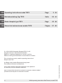 2
2
-
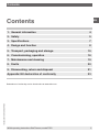 3
3
-
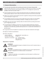 4
4
-
 5
5
-
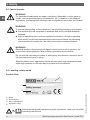 6
6
-
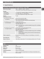 7
7
-
 8
8
-
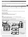 9
9
-
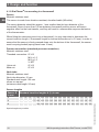 10
10
-
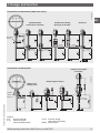 11
11
-
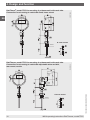 12
12
-
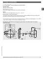 13
13
-
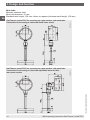 14
14
-
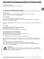 15
15
-
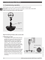 16
16
-
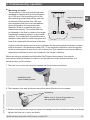 17
17
-
 18
18
-
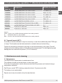 19
19
-
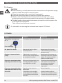 20
20
-
 21
21
-
 22
22
-
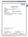 23
23
-
 24
24
-
 25
25
-
 26
26
-
 27
27
-
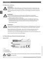 28
28
-
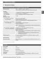 29
29
-
 30
30
-
 31
31
-
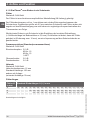 32
32
-
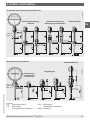 33
33
-
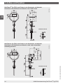 34
34
-
 35
35
-
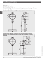 36
36
-
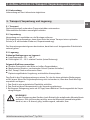 37
37
-
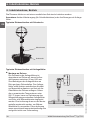 38
38
-
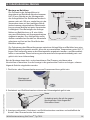 39
39
-
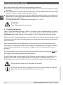 40
40
-
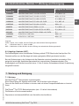 41
41
-
 42
42
-
 43
43
-
 44
44
-
 45
45
-
 46
46
-
 47
47
-
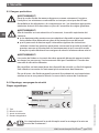 48
48
-
 49
49
-
 50
50
-
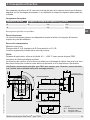 51
51
-
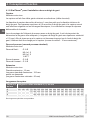 52
52
-
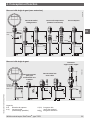 53
53
-
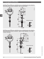 54
54
-
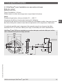 55
55
-
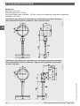 56
56
-
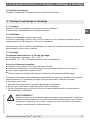 57
57
-
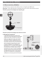 58
58
-
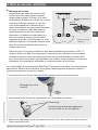 59
59
-
 60
60
-
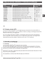 61
61
-
 62
62
-
 63
63
-
 64
64
-
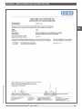 65
65
-
 66
66
-
 67
67
-
 68
68
-
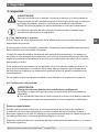 69
69
-
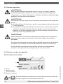 70
70
-
 71
71
-
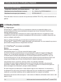 72
72
-
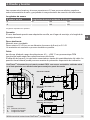 73
73
-
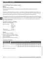 74
74
-
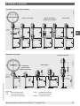 75
75
-
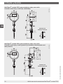 76
76
-
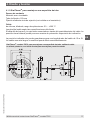 77
77
-
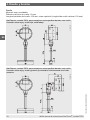 78
78
-
 79
79
-
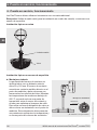 80
80
-
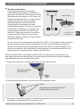 81
81
-
 82
82
-
 83
83
-
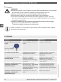 84
84
-
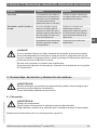 85
85
-
 86
86
-
 87
87
-
 88
88


En otros idiomas
- français: WIKA TR75 Mode d'emploi
- English: WIKA TR75 Operating instructions
- Deutsch: WIKA TR75 Bedienungsanleitung
Documentos relacionados
-
WIKA TR12 Manual de usuario
-
-
-
-
-
-
WIKA TR21-A tag:model:TR21-B tag:model:TR21-C Manual de usuario
-
-
-