MTD 31A-32AD762 El manual del propietario
- Categoría
- Lanzadores de nieve
- Tipo
- El manual del propietario
Este manual también es adecuado para

Safe Operation Practices • Set-Up • Operation • Maintenance • Service • Troubleshooting • Warranty
L
Two-Stage Snow Thrower m 300 Series
MTD LLC, P.O. BOX 361131 CLEVELAND, OHiO 44136-0019
PrintedInUSA FormNo.769-03940A
(June6,2008)

ToTheOwner
1
ThankYou
Thank you for purchasing a Snow Thrower manufactured by
MTD LLC. It was carefully engineered to provide excellent
performance when properly operated and maintained.
Please read this entire manual prior to operating the equipment.
It instructs you how to safely and easily set up, operate and
maintain your machine. Please be sure that you, and any other
persons who will operate the machine, carefully follow the
recommended safety practices at all times. Failure to do so could
result in personal injury or property damage.
All information in this manual is relative to the most recent
product information available at the time of printing. Review
this manual frequently to familiarize yourself with the unit, its
features and operation. Please be aware that this Operator's
Manual may cover a range of product specifications for various
models. Characteristics and features discussed and/or illustrated
in this manual may not be applicable to all models. MTD LLC
reserves the right to change product specifications, designs and
equipment without notice and without incurring obligation.
This product has met the rigid safety standards of the Outdoor
Power Equipment Institute and an independent testing
laboratory. If you have any problems or questions concerning the
unit, phone your local authorized MTD service dealer or contact
us directly. MTD's Customer Support telephone numbers,
website address and mailing address can be found on this page.
We want to ensure your complete satisfaction at all times.
Throughout this manual, all references to right and left side of the
machine are observed from the operating position
The engine manufacturer is responsible for all engine-related
issues with regards to performance, power-rating, specifications,
warranty and service. Please refer to the engine manufacturer's
Owner's/Operator's Manual, packed separately with your unit, for
more information.
Table of Contents
Safe Operation Practices ........................................ 3
Assembly & Set-Up .................................................. 7
Controls and Features ............................................ 11
Operation ................................................................ 13
Maintenance and Adjustments ............................ 13
Engine Maintenance .............................................. 17
RecordProduct Information
Before setting up and operating your new equipment, please
locate the model plate on the equipment and record the
information in the provided area to the right. You can locate the
model plate by standing at the operator's position and looking
down at the rear of the frame. This information will be necessary,
should you seek technical support via our web site, Customer
Support Department, or with a local authorized service dealer.
Service ..................................................................... 19
Troubleshooting ..................................................... 21
Replacement Parts ................................................ 22
Warranty ................................................................ 23
Espanol ................................................................... 26
MODEL NUMBER
D[31313131313131313D
SERIAL NUMBER
DF=IDF=IDF=IDF=IDF=ID
CustomerSupport
Please do NOT return the unit to the retailer or dealer without first contacting our Cu;tomer Support Department.
If you have difficulty assembling this product or have any questions regarding the controls, operation, or maintenance of
this unit, you can seek help from the experts. Choose from the options below:
0 Visit us on the web at www.mtdproducts.com
0 Call a Customer Support Representative at (800) 800-7310 or (330) 220-4683
0 Write us at MTD LLC • RO. Box 361131 • Cleveland, OH • 44136-0019

ImportantSafeOperationPractices
2
WARNING! This symbol points out important safety instructions which, if not followed,
could endanger the personal safety and/or property of yourself and others. Read and follow
all instructions in this manual before attempting to operate this machine. Failure to comply
with these instructions may result in personal injury.
When you see this symbol. HEED ITS WARNING!
CALIFORNIA PROPOSITION 65
WARNING! Engine Exhaust, some of its constituents, and certain vehicle components
contain or emit chemicals known to State of California to cause cancer and birth defects
or other reproductive harm.
DANGER: This machine was built to be operated according to the safe operation practices in
this manual. As with any type of power equipment, carelessness or error on the part of the
operator can result in serious injury. This machine is capable of amputating fingers, hands,
toes and feet and throwing foreign objects. Failure to observe the following safety
instructions could result in serious injury or death.
Training Preparation
1. Read, understand, and follow all instructions on the
machine and in the manual(s) before attempting to
assemble and operate. Keep this manual in a safe place for
future and regular reference and for ordering replacement
pa rts.
2. Be familiar with all controls and their proper operation.
Know how to stop the machine and disengage them
quickly.
3. Never allow children under 14 years of age to operate this
machine. Children 14 and over should read and understand
the instructions and safe operation practices in this manual
and on the machine and be trained and supervised by an
adult.
4. Never allow adults to operate this machine without proper
instruction.
5. Thrown objects can cause serious personal injury. Plan
your snow-throwing pattern to avoid discharge of material
toward roads, bystanders and the like.
6. Keep bystanders, pets and children at least 75 feet from the
machine while it is in operation. Stop machine if anyone
enters the area.
Exercise caution to avoid slipping or falling, especially
when operating in reverse.
Thoroughly inspect the area where the equipment is to be used.
Remove all doormats, newspapers, sleds, boards, wires and other
foreign objects, which could be tripped over or thrown by the
auger/impeller.
1. Always wear safety glasses or eye shields during operation
and while performing an adjustment or repair to protect
your eyes. Thrown objects which ricochet can cause serious
injury to the eyes.
2. Do not operate without wearing adequate winter outer
garments. Do not wear jewelry, long scarves or other loose
clothing, which could become entangled in moving parts.
Wear footwear which will improve footing on slippery
surfaces.
3. Use a grounded three-wire extension cord and receptacle
for all machines with electric start engines.
4. Adjust collector housing height to clear gravel or crushed
rock surfaces.
5. Disengage all control levers before starting the engine.
6. Never attempt to make any adjustments while engine is
running, except where specifically recommended in the
operator's manual.
7. Let engine and machine adjust to outdoor temperature
before starting to clear snow.

SafeHandling of Gasoline
To avoid personal injury or property damage use extreme care
in handling gasoline. Gasoline is extremely flammable and the
vapors are explosive. Serious personal injury can occur when
gasoline is spilled on yourself or your clothes which can ignite.
Wash your skin and change clothes immediately.
a. Use only an approved gasoline container.
b. Extinguish all cigarettes, cigars, pipes and other
sources of ignition.
Never fuel machine indoors.
C.
d.
Never remove gas cap or add fuel while the engine is
hot or running.
e. Allow engine to cool at least two minutes before
refueling.
f. Never over fill fuel tank. Fill tank to no more than 1/2
inch below bottom of filler neck to provide space for
fuel expansion.
g. Replace gasoline cap and tighten securely.
h. If gasoline is spilled, wipe it off the engine and
equipment. Move machine to another area. Wait 5
minutes before starting the engine.
i. Never store the machine or fuel container inside
where there is an open flame, spark or pilot light
(e.g. furnace, water heater, space heater, clothes
dryer etc.).
j. Allow machine to cool at least 5 minutes before
storing.
k. Never fill containers inside a vehicle or on a truck
or trailer bed with a plastic liner. Always place
containers on the ground away from your vehicle
before filling.
I. If possible, remove gas-powered equipment from
the truck or trailer and refuel it on the ground. If this
is not possible, then refuel such equipment on a
trailer with a portable container, rather than from a
gasoline dispenser nozzle.
m. Keep the nozzle in contact with the rim of the fuel
tank or container opening at all times until fueling is
complete. Do not use a nozzle lock-open device.
Operation
1. Do not put hands or feet near rotating parts, in the auger/
impeller housing or chute assembly. Contact with the
rotating parts can amputate hands and feet.
2. The auger/impeller control lever is a safety device. Never
bypass its operation. Doing so makes the machine unsafe
and may cause personal injury.
3. The control levers must operate easily in both directions
and automatically return to the disengaged position when
released.
4.
Never operate with a missing or damaged chute assembly.
Keep all safety devices in place and working.
5. Never run an engine indoors or in a poorly ventilated area.
Engine exhaust contains carbon monoxide, an odorless
and deadly gas.
6. Do not operate machine while under the influence of
alcohol or drugs.
7. Muffler and engine become hot and can cause a burn. Do
not touch. Keep children away.
8. Exercise extreme caution when operating on or crossing
gravel surfaces. Stay alert for hidden hazards or traffic.
9. Exercise caution when changing direction and while
operating on slopes.
10. Plan your snow-throwing pattern to avoid discharge
towards windows, walls, cars etc. Thus, avoiding possible
property damage or personal injury caused by a ricochet.
11. Never direct discharge at children, bystanders and pets or
allow anyone in front of the machine.
12. Do not overload machine capacity by attempting to clear
snow at too fast of a rate.
13.
14.
15.
Never operate this machine without good visibility or light.
Always be sure of your footing and keep a firm hold on the
handles. Walk, never run.
Disengage power to the auger/impeller when transporting
or not in use.
Never operate machine at high transport speeds on
slippery surfaces. Look down and behind and use care
when backing up.
16. If the machine should start to vibrate abnormally, stop
the engine, disconnect the spark plug wire and ground it
against the engine. Inspect thoroughly for damage. Repair
any damage before starting and operating.
17. Disengage all control levers and stop engine before you
leave the operating position (behind the handles). Wait
until the auger/impeller comes to a complete stop before
unclogging the chute assembly, making any adjustments,
or inspections.
18. Never put your hand in the discharge or collector
openings. Always use the clean-out tool provided to
unclog the discharge opening. Do not unclog chute
assembly while engine is running. Shut off engine and
remain behind handles until all moving parts have stopped
before unclogging.
19. Use only attachments and accessories approved by the
manufacturer (e.g. wheel weights, tire chains, cabs etc.).
20. When starting engine, pull cord slowly until resistance
is felt, then pull rapidly. Rapid retraction of starter cord
(kickback) will pull hand and arm toward engine faster than
you can let go. Broken bones, fractures, bruises or sprains
could result.
21.
If situations occur which are not covered in this manual, use
care and good judgment. Contact Customer Support for
assistance and the name of your nearest servicing dealer.
4 I SECTION 2 -- IMPORTANT SAFE OPERATION PRACTICES

Maintenance & Storage
1. Never tamper with safety devices. Check their proper
operation regularly. Refer to the maintenance and
adjustment sections of this manual.
2. Before cleaning, repairing, or inspecting machine
disengage all control levers and stop the engine. Wait until
the auger/impeller come to a complete stop. Disconnect
the spark plug wire and ground against the engine to
prevent unintended starting.
3. Check bolts and screws for proper tightness at frequent
intervals to keep the machine in safe working condition.
Also, visually inspect machine for any damage.
4. Do not change the engine governor setting or over-speed
the engine. The governor controls the maximum safe
operating speed of the engine.
5. Snow thrower shave plates and skid shoes are subject to
wear and damage. For your safety protection, frequently
check all components and replace with original equipment
manufacturer's (OEM) parts only. "Use of parts which do
not meet the original equipment specifications may lead to
improper performance and compromise safety!"
6. Check control levers periodically to verify they engage
and disengage properly and adjust, if necessary. Refer
to the adjustment section in this operator's manual for
instructions.
7. Maintain or replace safety and instruction labels, as
necessary.
8. Observe proper disposal laws and regulations for gas, oil,
etc. to protect the environment.
9. Prior to storing, run machine a few minutes to clear snow
from machine and prevent freeze up of auger/impeller.
10. Never store the machine or fuel container inside where
there is an open flame, spark or pilot light such as a water
heater, furnace, clothes dryer etc.
11. Always refer to the operator's manual for proper
instructions on off-season storage.
12. Check fuel line, tank, cap, and fittings frequently for cracks
or leaks. Replace if necessary.
13. Do not crank engine with spark plug removed.
14. According to the Consumer Products Safety Commission
(CPSC) and the U.S. Environmental Protection Agency (EPA),
this product has an Average Useful Life of seven (7) years,
or 60 hours of operation. At the end of the Average Useful
Life have the machine inspected annually by an authorized
service dealer to ensure that all mechanical and safety
systems are working properly and not worn excessively.
Failure to do so can result in accidents, injuries or death.
Donot modify engine
To avoid serious injury or death, do not modify engine in any
way. Tampering with the governor setting can lead to a runaway
engine and cause it to operate at unsafe speeds. Never tamper
with factory setting of engine governor.
Notice Regarding Emissions
Engines which are certified to comply with California and federal
EPA emission regulations for SORE (Small Off Road Equipment)
are certified to operate on regular unleaded gasoline, and
may include the following emission control systems: Engine
Modification (EM), Oxidizing Catalyst (OC), Secondary Air
Injection (SAI) and Three Way Catalyst (TWC) if so equipped.
SparkArrestor
_ ARNING! This machine is equipped with an
internal combustion engine and should not be used
on or near any unimproved forest-covered, brush
covered or grass-covered land unless the engine's
exhaust system is equipped with a spark arrester
meeting applicable local or state laws (if any).
Ira spark arrester is used, it should be maintained in effective
working order by the operator. In the State of California the
above is required by law (Section 4442 of the California Public
Resources Code). Other states may have similar laws. Federal laws
apply on federal lands.
A spark attester for the muffler is available through your
nearest engine authorized service dealer or contact the service
department, P.O.Box 361131 Cleveland, Ohio 44136-0019.
SECTION 2 -- IMPORTANT SAFE OPERATION PRACTICES S

Safety Symbols
This page depicts and describes safety symbols that may appear on this product. Read, understand, and follow all instructions on the
machine before attempting to assemble and operate.
........!i........
READ THE OPERATOR'S MANUAL(S)
Read, understand, and follow all instructions in the manual(s) before attempting to
assemble and operate
WARNING-- ROTATING BLADES
Keep hands out of inlet and discharge openings while machine is running. There are rotating
blades inside
WARNING-- ROTATING BLADES
Keep hands out of inlet and discharge openings while machine is running. There are rotating
blades inside
WARNING-- ROTATING AUGER
Do not put hands or feet near rotating parts, in the auger/impeller housing or chute
assembly. Contact with the rotating parts can amputate hands and feet.
WARNING--THROWN OBJECTS
This machine may pick up and throw and objects which can cause serious personal injury.
WARNING--GASOLINE ISFLAMMABLE
Allow the engine to cool at least two minutes before refueling.
WARNING-- CARBON MONOXIDE
Never run an engine indoors or in a poorly ventilated area. Engine exhaust contains carbon
monoxide, an odorless and deadly gas.
WARNING-- ELECTRICAL SHOCK
Do not use the engine's electric starter in the rain
WARNING! Your Responsibility--Restrict the use of this power machine to persons who read, understand and
follow the warnings and instructions in this manual and on the machine.
SAVETHESEINSTRUCTIONS!
6 I SECTION 2 -- IMPORTANT SAFE OPERATION PRACTICES

Assembly& Set-Up
3
Contentsof Carton
One Snow Thrower
One Snow Thrower Operator's
Manual
Two Replacement Auger Shear Pins
One Product Registration Card
One Chute Assembly
Assembly
Setting UpTheHandle
I. Remove cable tie (if present) securing upper handle to
lower handle for shipping purposes. Remove all protective
plastic wrapping from handles.
NOTE: Be careful NOT to remove the three loosely fitted
cable ties that will be utilized later to secure cables.
2.
Loosen and remove the wing knob, saddle washer, handle
tab and carriage screw on each side of the lower handle.
See Fig. 3-1.
3.
Figure 3-1
Slide one of the loosely fitted cable ties from the right side
of the lower handle up to the cross member of the lower
handle. Leave the second cable tie in place on the right side
of the lower handle. See Fig. 3-3 for reference.
IMPORTANT: It will be necessary to lift the upper handle while
sliding up this cable tie to prevent damage to the cable.
4. Lift the upper handle up and position it over the lower
handle, aligning the holes where the wing knobs were
removed (1).SeeFig. 3-2.
CAUTION: Be careful not to bend or kink the cables.
5. Insert a carriage screw from the outside through a handle
tab, the upper and lower handles, a saddle washer and into
the wing knob (2). Repeat on the other side.
6. Tighten the wing knobs on each side of the handle. Refer
to Fig. 3-2.
7.
Figure 3=2
NOTE:The auger cable routes down the left lower handle
and the drive cable is routed across the top of the lower
handle and down the right side of the lower handle. See
Fig. 3-3.
Three cable ties have been used to loosely tie the control
cables to the lower handle, including the cable tie you
relocated in step 3. Position cable ties now, as in Fig. 3-3,
and tighten to secure cables to the lower handle. Trim off
excess material of cable ties.
er Cable
Figure 3-3

Set-Up
ShearPins
A pair of replacement auger shear pins and bow tie cotter pins
are included with your snow thrower. See Fig. 3-4. Store them in
a safe place until needed.
Figure 3-4
ChuteClean-0utTool
The chute clean-out tool is fastened to the top of the auger
housing with a mounting clip and a cable tie at the factory. Cut
the cable tie before operating the snow thrower. See Fig. 3-5.
Chute Clean=out Tool
Figure 3-5
TirePressure
The proper inflation pressure is between 15 psi and 20 psi. Check
the tire pressure periodically and maintain equal pressure in
both tires at all times. Excessive pressure (well above 20 psi) may
cause the wheel (tire/rim) assembly to burst with sufficient force
to cause serious injury. Do not over-inflate the tire. Use a manual
pump or portable electric tire inflator to prevent over-inflation.
NEVER USE AN AIR COMPRESSOR.
FuelRec0mmedati0ns
Use automotive gasoline (unleaded or low leaded to minimize
combustion chamber deposits) with a minimum of 87 octane.
Gasoline with up to 10% ethanol or 15% MTBE (Methyl Tertiary
Butyl Ether) can be used. Never use an oil/gasoline mixture or
dirty gasoline. Avoid getting dirt, dust, or water in the fuel tank.
DO NOT use E85 gasoline.
Refuel in a well-ventilated area with the engine stopped.
Do not smoke or allow flames or sparks in the area where
the engine is refueled or where gasoline is stored.
Do not overfill the fuel tank. After refueling, make sure the
tank cap is closed properly and securely.
Be careful not to spill fuel when refueling. Spilled fuel or
fuel vapor may ignite. If any fuel is spilled, make sure the
area is dry before starting the engine.
Avoid repeated or prolonged contact with skin or
breathing of vapor.
Adding Fuel
WARNING! Use extreme care when handling
gasoline. Gasoline is extremely flammable and the
vapors are explosive. Never fuel the machine
indoors or while the engine is hot or running.
Extinguish cigarettes, cigars, pipes and other
sources of ignition.
WARNING! Always keep hands and feet clear of
equipment moving parts. Do not use a pressurized
starting fluid. Vapors are flammable.
1.
2.
Clean around fuel fill before removing cap to fuel.
A fuel level indicator is located in the fuel tank. Fill tank
until fuel reaches the fuel level indictor, Fig. 3-6. Be careful
not to overfill.
8 I SECTION3 -- ASSEMBLY& SET-UP

Fuel Level Indicator
TopView
Figure 3-6
CheckingOilLevel
_ii AUTION: The engine is shipped with oil in the
engine. You must, however, check the oil level prior
to operating the snow thrower. Running the engine
with insufficient oil can cause serious engine
damage and void the engine warranty.
NOTE: Be sure to check the engine on a level surface with the
engine stopped.
1. Remove the oil filler cap/dipstick and wipe the dipstick
clean. See Fig. 3-7.
2.
3.
J
Figure 3-7
Insert the cap/dipstick into the oil filler neck, but do not
screw it in.
Remove the oil filler cap/dipstick. If the level is low, slowly
add oil until oil level registers between high (H) and low
(L), Fig. 3-7. Refer to the Engine Maintenance section for
correct oil viscosity and engine oil capacity.
4.
NOTE:Do not overfill. Overfilling with oil may result in
engine smoking, hard starting or spark plug fouling.
Replaceand tighten cap/dipstick firmly before starting
engine.
Adjustments
SkidShoe
The snow thrower skid shoes are adjusted upward at the factory
for shipping purposes. Adjust them downward, if desired, prior
to operating the snow thrower.
CAUTION : It is not recommended that you operate
this snow thrower on gravel as it can easily pick up
and throw loose gravel, causing personal injury or
damage to the snow thrower and surrounding
property.
For close snow removal on a smooth surface, raise skid
shoes higher on the auger housing.
Use a middle or lower position when the area to be cleared
is uneven, such as a gravel driveway
NOTE: If you choose to operate the snow thrower on a gravel
surface, keep the skid shoes in position for maximum clearance
between the ground and the shave plate.
To adjust the skid shoes:
Loosen the four hex nuts (two on each side) and carriage
bolts. Move skid shoes to desired position. See Fig. 3-8.
/ /
/ /
/
/
/
/
Figure 3-8
2. Make certain the entire bottom surface of skid shoe is
against the ground to avoid uneven wear on the skid shoes.
3. Retighten nuts and bolts securely.
SECTION 3 -- ASSEMBLY& SET-UP 9

DischargeChute
1. Loosen the wing knob on the upper chute, adjust chute
and chute control to desired operating position.
2. Tighten the wing knob on the upper chute making sure the
carriage bolt is correctly positioned. Refer to Fig. 3-9.
,. j
Figure 3-9
AugerControl
Periodic adjustment to the auger control cable may be required
due to normal stretch and wear on the belt. Adjustment is
needed immediately if the augers:
a. Continue to turn with the auger control disengaged,
or
b. During operation, augers seem to hesitate turning
while the engine maintains speed.
NOTE: Perform the following test before operating the snow
thrower for the first time and at the start of each winter season.
Check the adjustment of the auger control as follows:
1. When the auger control is released and in the disengaged
"up" position, the cable should have very little slack, but
should NOT be tight.
2. In a well-ventilated area, start the snow thrower engine.
Refer to Starting The Engine in the Operation section
on this manual. Make sure the throttle is set in the FAST
position.
3. While standing in the operator's position (behind the snow
thrower) engage the auger.
4. Allow the auger to remain engaged for approximately 10
seconds before releasing the auger control. Repeat this
several times.
5. With the engine running in the FAST position and the
auger control in the disengaged "up" position, walk to the
front of the machine.
6. Confirm that the auger has completely stopped rotating
and shows NO signs of motion.
NOTE: If the auger shows ANY signs of rotating, immediately
return to the operator's position and shut off the engine. Wait for
all moving parts to stop before adjusting the auger control cable
as follows:
7.
Loosen the rear hex bolt on the cable adjustment bracket.
See Fig. 3-10.
Figure 3-10
8. Slide the cable adjustment bracket forward adding a slight
amount of slack in the auger cable.
9. Retighten the rear hex bolt.
10. Start engine and verify auger control engages and
disengages properly.
NOTE: If auger continues to rotate with the control
disengaged, shut off engine and readjust.
11. If during operation, augers seem to hesitate turning while
the engine maintains speed, then the cable is too loose and
the bracket needs to be adjusted rearward, decreasing the
amount of slack to the auger cable. Follow the above steps
to adjust the cable adjustment bracket.
WARNING! Do not over-tighten the cable.
Overtightening may prevent the auger from
disengaging and compromise the safety of the snow
thrower.
SECTION 3 -- ASSEMBLY& SET-UP

ControlsandFeatures
4
Auger Control
DriveControl
StarterRope
FuelCap
UpperChute
ChuteAssembly
Clean-outTool
Auger
ShavePlate
ChuteKnob
SkidShoe
Figure 4-1
DriveControl
Located on the underside of the upper handle, the drive control
is used to engage/disengage wheels. Squeeze the drive control
against the upper handle to engage the wheels; release to
disengage.
ignition Key
The ignition key is a safety device. It must be fully inserted in
order for the engine to start. Remove the ignition key when the
snow thrower is not in use.
NOTE: Do not turn the ignition key in an attempt to start the
engine. Doing so may cause it to break.
Starter Rope
The starter rope is part of the recoil starter and is used to start
the engine.
Auger
When engaged, the auger's rotation draw snow into the auger
housing and throws it out the discharge chute.
Muffler
FuelCap
Recoil Starter
Handle
Oil Cap
OilDrain
,J
J
ChuteAssembly
Snow drawn into the auger housing is discharged out of the
chute assembly
AugerControl
The auger control is adjacent to the upper handle. Squeeze the
auger control against the upper handle to engage the augers;
release to disengage the augers.
_ ARNING! Never make adjustments to the chute
assembly unless both auger and drive controls are
disengaged and the operator is standing beside the
unit.
IMPORTANT: Refer to the Auger Control information in
the Assembly & Set-Up section prior to operating your snow
thrower. Read and follow all instructions carefully and perform all
adjustments to verify your snow thrower is operating safely and
properly.
11

ChuteHandle
The direction of snow throwing corresponds to the direction
of the chute opening. Use the chute handle to turn the chute
assembly in the direction you wish to throw the snow.
ChuteKnob
The distance snow is thrown can be adjusted by either raising
or lowering the upper chute. Loosen the chute knob on the side
of the upper chute to adjust. Pivot the upper chute to desired
position, and retighten the chute knob.
ShavePlate
The shave plate maintains contact with pavement as the snow
thrower is propelled, allowing snow close to pavement's surface
to be discharged.
SkidShoes
Position the skid shoes based on surface conditions. Adjust
upward for hard-packed snow. Adjust downward when
operating on gravel or crushed rock surfaces.
FuelCap
Unthread the gas cap to add gasoline to the fuel tank. This unit
runs on regular gas.
OilCap
Engine oil level can be checked and oil added through the oil fill.
NOTE:The engine is shipped with oil in it. Check the oil level
before the first use and add if necessary, as specified in the
separate engine manual packed with your snow thrower. Always
check the oil level prior to each use.
Oil Drain
Engine oil can be drained through the oil drain.
Muffler
Engine exhaust exists the engine via the muffler.
ChokeControl
The choke control is found on the rear of
the engine and is activated by rotating the
knob counter-clockwise. Activating the
choke control closes the choke plate on the
carburetor and aids in starting the engine.
Primer
Pressing the primer forces fuel directly
into the engine's carburetor to aid in cold-
weather starting.
|
ThrottleControl
The throttle control is located on the rear of the engine. It
regulates the speed of the engine and will shut offthe engine
when moved into the STOP position.
RecoilStarterHandle
This handle is used to manually start the engine.
ChuteAssembly
Snow drawn into the auger housing is discharged out the chute
assembly.
ChuteClean-OutTool
_ ARNING! Never use your hands to clear a
clogged chute assembly. Shut offengine and remain
behind handles until all moving parts have stopped
before unclogging.
The chute clean-out tool is conveniently fastened to the rear of
the auger housing with a mounting clip. Should snowand ice
become lodged in the chute assembly during operation, proceed
as follows to safely clean the chute assembly and chute opening:
1. Release both the Auger Control and the Drive Control.
2. Stop the engine by removing the ignition key.
3. Remove the clean-out tool from the clip which secures it to
the rear of the auger housing.
4. Use the shovel-shaped end of the clean-out tool to
dislodge and scoop any snow and ice which has formed in
and near the chute assembly.
5. Refasten the clean-out tool to the mounting clip on the
rear of the auger housing, reinsert the ignition key and
start the snow thrower's engine.
While standing in the operator's position (behind the snow
thrower), engage the auger control for a few seconds to clear any
remaining snow and ice from the chute assembly.
12 I SECTION 4-- CONTROLS AND FEATURES

Operation
Starting the Engine
_ ARNING! Always keep hands and feet clear of
moving parts. Do not use a pressurized starting
fluid. Vapors are flammable.
NOTE: Allow the engine to warm up for a few minutes after
starting. The engine will not develop full power until it reaches
operating temperatures.
RecoilStarter
CAUTION! Do not pull the starter handle while the
engine running.
WARNING; To avoid unsupervised engine
operation, never leave the engine unattended while
running. Turn the engine off after use and remove
ignition key
1. Insert ignition key fully into slot, Figure 5-1. Make sure it
snaps into place. DO NOTturn ignition key. The engine
cannot start unless the key is inserted into ignition switch.
5. Pull gently on the starter handle until it begins to
resist, then pull quickly and forcefully to overcome the
compression. Do not release the handle and allow it to
snap back. Return rope SLOWLY to original position. If
required, repeat this step.
6. As the engine warms, slowly rotate the choke control to
OFF position. If the engine falters, restart engine and run
with choke at half-choke position for a short period of time,
and then slowly rotate the choke into OFF position.
Stopping the Engine
i_klk WARNING: To avoid unsupervised engine
operation, never leave the machine unattended
with the engine running. Turn the engine off after
use and remove ignition key
Run engine for a few minutes before stopping to help dry offany
moisture on the engine.
1. Move throttle control to STOP position.
2. Remove the ignition key. Removing the key will reduce the
possibility of unauthorized starting of the engine while
equipment is not in use. Keep the key in a safe place. The
engine cannot start without the ignition key.
3. Wipe any moisture away from the controls on the engine.
ToEngageDrive
1.
2.
Move the throttle control into the Fast (rabbit) position.
To engage the drive, squeeze the drive control completely
against the upper handle to engage the wheels. To stop
the forward motion, release the drive control.
ToEngageAugers
To engage the augers, squeeze the auger control handle
completely against the upper handle. To stop the augers,
release handle.
Figure 5-1
2. Move throttle control to FAST (rabbit) position.
3. Move choke to the ON position (cold engine start). If engine
is warm, place choke in OFF position.
4. Push primer three to five (3-5) times, making sure to cover
vent hole when pushing. If engine is warm, push primer
only once. Always cover vent hole when pushing. Cool
weather may require priming to be repeated.
13

ReplacingShearPins
The augers are secured to the spiral shaft with two shear pins
and cotter pins. If the auger should strike a foreign object or ice
jam, the snow thrower is designed so that the pins may shear. If
the augers will not turn, check to see if the pins have sheared.
See Fig. 5-2.
Figure 5-2
CAUTION: NEVER replace the auger shear pins with
anything other than OEM Part No.738-04124A
replacement shear pins. Any damage to the auger
gearbox or other components as a result of failing to
do so will NOT be covered by your snow thrower's
war ranty.
WARNING! Always turn off the snow thrower's
engine and remove the key prior to replacing shear
pins.
SECTION S -- OPERATION

Maintenance&Adjustments
Maintenance
GeneralRecommendations
Always observe safety rules when performing any type of
maintenance.
The warranty on this snow thrower does not cover items
that have been subjected to operator abuse or negligence.
To receive full value from the warranty, operator must
maintain the snow thrower as instructed in this manual.
Periodically check all fasteners and hardware to make sure
these are tight.
i_i WARNING! Before servicing, repairing, lubricating,
or inspecting, disengage all controls and stop
engine. Wait until all moving parts have come to a
complete stop. Disconnect spark plug wire and
ground it against the engine to prevent unintended
starting. Always wear safety glasses during
operation or while performing any adjustments or
repairs.
Engine
Listed below are general recommendations about maintaining
your snow thrower engine. For further details, refer to the Engine
Maintenance Section.
1. Before operating snow thrower, check the oil level.
2. Change engine oil after first five hours of operation and
every 25 hours thereafter.
3. Clean spark plug and reset the electrode gap to 0.030"
at least once a season or every 100 hours of operation;
replace every 200 hours of operation.
TirePressure
Before operating, check tire pressure and reduce pressure to
between 15 psi and 20 psi. Refer to Setup in the Assembly and
Setup section of this manual for proper filling procedures.
If the tire pressure is not equal in both tires, the unit may pull to
one side or the other.
CheckV-Belts
Follow instructions below to check condition of drive belts every
50 hours of operation.
1. Remove the plastic belt cover on the front of the engine by
removing the self-tapping screw and pressing the plastic
tabs to release the belt cover. See Fig. 8-1 in the Service
section of this manual.
2.
Visually inspect for frayed, cracked, or excessively worn out
belts. Replace, if necessary, following instructions in the
Service section of this manual.
ShavePlateand SkidShoes
The shave plate and skid shoes on the bottom of the snow
thrower are subject to wear. These should be checked
periodically and replaced when necessary.
To replace skid shoes:
1. Remove the carriage bolts and nuts securing each skid shoe
to the auger housing, See Fig. 6-1.
2. Reassemble new skid shoes with hardware just removed.
Make sure the skid shoes are adjusted to be level.
\\
Figure 6-1
To remove shave plate:
3. Remove both skid shoes and hardware including carriage
bolts and nuts which attach shave plate to the snow
thrower housing. For location of shave plate, see Fig. 6-1.
4. Reassemble new shave plate, making sure heads of the
carriage bolts are to the inside of the housing.
5. Reinstall skid shoes. Tighten securely.
Off-SeasonStorage
If the snow thrower will not be used for 30 days or longer, or if it
is the end of the snow season when the last possibility of snow is
gone, the equipment needs to be stored properly. Follow storage
instructions below to ensure top performance from the snow
thrower for many more years.
1. Store the equipment in a clean, dry area.
2. If storing the snow thrower in an unventilated area,
rustproof the machine using a light oil or silicone to coat
the snow thrower.
3. Clean the exterior of the engine and the snow thrower.
15

Preparing TheEngine
WARNING! Never store the snow thrower with fuel
in the tank indoors or in poorly ventilated areas,
where fuel fumes may reach an open flame, spark or
pilot light as on a furnace, water heater, clothes
dryer or gas appliance.
NOTE; It is important to prevent gum deposits from forming in
essential fuel system parts of the engine such as the carburetor,
fuel filter, fuel hose or tank during storage.
CAUTION: Alcohol blended fuels (called gasohol or using
ethanol or methanol) can attract moisture which leads to
separation and formation of acids during storage. Acidic gas can
damage the fuel system of an engine while in storage.
To avoid engine problems, the fuel system should be emptied
before storage for 30 days or longer. Follow these instructions to
prepare your snow thrower for storage:
1.
WARNING! Drain fuel into an approved container
outdoors, away from any open flame. Be certain
engine is cool. Do not smoke. Fuel left in engine
during warm weather deteriorates and will cause
serious starting problems.
Run the engine until the fuel tank is empty and it stops due
to lack of fuel.
WARNING! Do not drain carburetor if using fuel
stabilizer. Never use engine or carburetor cleaning
products in the fuel tank or permanent damage may
occur.
2.
NOTE: Fuel stabilizer (such as STA-BIL TM or ULTRA-FRESH TM)
is an acceptable alternative in minimizing the formation
of fuel gum deposits during storage. Add stabilizer to
gasoline in fuel tank or storage container. Always follow
mix ratio found on stabilizer container. Run engine at least
10 minutes after adding stabilizer to allow it to reach the
carburetor. Do not drain carburetor if using fuel stabilizer.
Remove the spark plug and pour one (1) ounce of engine
oil through the spark plug hole into the cylinder. Cover
spark plug hole with a rag and crank the engine several
times to distribute the oil. Replace spark plug.
PreparingTheSnowThrower
1. When storing the snow thrower in an unventilated or
metal storage shed, care should be taken to rustproof the
equipment. Using a light oil or silicone, coat the equipment,
especially any chains, springs, bearings and cables.
2. Remove all dirt from exterior of engine and equipment.
3. Follow lubrication recommendations in the Maintenance
section of this manual.
4. Store equipment in a clean, dry area.
Lubrication
1. Lubricate pivot points on the auger control and drive
control with a light engine oil once a season, see Fig. 6-2.
Figure 6-2
2.
Lubricate the auger idler bracket with a light engine oil
once a season. See Fig. 6-2.
AugerShaft
At least once a season, remove the shear pins from the auger
shaft. Spray lubricant inside the shaft and around the spacers
and the flange bearings found at either end of the shaft.
See Fig. 6-3.
f
J
Figure 6-3
Wheels
At least once a season, remove both wheels. Clean and coat the
axles with a multipurpose automotive grease before reinstalling
wheels.
SECTION 6-- MAINTENANCE & ADJUSTMENTS

EngineMaintenance
7
WARNING! To prevent accidental start-up, shut off
the engine and remove the ignition key before
performing any type of engine maintenance.
Periodic inspection and adjustment of the engine is essential if
high level performance is to be maintained. Regular maintenance
will also ensure a long service life. The required service intervals
and the type of maintenance to be performed are described
in the table below. Follow the hourly or calendar intervals,
whichever occur first. More frequent service is required when
operating in adverse conditions.
MaintenanceSchedule
Tasks First 5 Hrsl Each Use or' Every Season ' Every Season Every seaSon
. Every 5 Hrs. or25 Hrs. or 50 Hrs. or 100 Hrs. I
Check engine oil •
Change engine oil I I I I
Check spark plug ®
service Spark plug i i .
Clean exhaust area •
ChangingEngineOil
NOTE: Check the oil level before each use and after every five
hours of operation to be sure correct oil level is maintained. Refer
to Checking Oil Level in the Operation section
1. Drain fuel from tank by running engine until the fuel tank is
empty. Be sure fuel fill cap is secure.
2. Place suitable oil collection container under oil drain plug.
3. Remove oil drain plug, Figure 7-1.
\ _,,,
Oil Pluc
6. Refill with the recommended oil and check the oil level,
refer to Operation section for instructions.
7. Reinstall the oil filler cap/dipstick securely.
_lk AUTION: Thoroughly wash your hands with soap
and water as soon as possible after handling
used oil,
NOTE: Pleasedispose of used motor oil in a manner that is
friendly to the environment. Takeit to a recyling center or other
collection center.
Oil Recommendations
When adding oil to the engine, refer to viscosity chart below.
Engine oil capacity is 600 ml (approx. 20 oz.). Do not over-fill.
Use a 4-stroke, or an equivalent high detergent, premium
quality motor oil certified to meet or exceed U.S. automobile
manufacturer's requirements for service classification SG, SF.
Motor oils classified SG, SF will show this designation on the
container.
(°F)-40o-20 o 0o 200
(°c) -30° -20° -10°
400
0
4.
Figure 7-1
Tip engine to drain oil into the container. Used oil must be
disposed of at a proper collection center.
CAUTION: DO NOT use nondetergent oil or
2-stroke engine oil. It could shorten the engine's
service life.
5. Reinstall the drain plug and tighten it securely.
17

SparkPlug
i_ WARNING! DO NOT check for spark with spark
plug removed. DO NOT crank engine with spark
plug removed.
i_ WARI!ING! If the engine has been running, the
muffler will be very hot. Be careful not to touch the
muffler.
To ensure proper engine operation, the spark plug must be
properly gapped and free of deposits.
1. Remove the spark plug boot and use a spark plug wrench
to remove the plug, Figure 7-2.
2_
3_
/
Spark Plug Boot
Figure 7-2
J
Visually inspect the spark plug. Discard the spark plug
if there is apparent wear, or if the insulator is cracked or
chipped. Clean the spark plug with a wire brush if it is to be
reused.
Measure the plug gap with a feeler gauge. Correct as
necessary by bending side electrode, Figure 7-3. The gap
should be set to .02-.03 inches (0.60-0.80 mm).
f Electrode
_____ .__ ° =° " o
(0.60-0.80 ram)
Figure 7-3
4_
5_
Check that the spark plug washer is in good condition
and thread the spark plug in by hand to prevent cross-
threading.
After the spark plug is seated, tighten with a spark plug
wrench to compress the washer.
NOTE:When installing a new spark plug, tighten 1/2-turn
after the spark plug seats to compress the washer. When
reinstalling a used spark plug, tighten Ys-to 1/4-turn after
the spark plug seats to compress the washer.
_ CAUTION! The spark plug must be tightened
securely. A loose spark plug can become very hot
and can damage the engine.
Cleaningthe Engine
If the engine has been running, allow it to cool for at least half
an hour before cleaning. Periodically remove dirt build-up from
engine.
CAUTION! Do not spray engine with water to clean
because water could contaminate fuel. Using a
garden hose or pressure washing equipment can
also force water into the muffler opening. Water that
passes through the muffler can enter the cylinder,
causing damage.
_ ARNING! Accumulation of debris around muffler
could cause a fire. Inspect and clean before every
use.
Off-SeasonStorage
Engines stored over 30 days need to be drained of fuel to
prevent deterioration and gum from forming in fuel system
or on essential carburetor parts. If the gasoline in your engine
deteriorates during storage, you may need to have the
carburetor, and other fuel system components, serviced or
replaced.
1. Remove all fuel from tank by running engine until it stops.
2. Change the engine oil.
3. Remove spark plug and pour approximately 1 oz. (30 ml)
of clean engine oil into the cylinder. Pull the recoil starter
several times to distribute the oil, and reinstall the spark
plug.
4. Clean debris from around engine, and under, around, and
behind muffler. Apply a light film ofoil on any areas that
are susceptible to rust.
Store in a clean, dry and well ventilated area away from any
appliance that operates with a flame or pilot light, such as a
furnace, water heater, or clothes dryer. Avoid any area with
a spark producing electric motor, or where power tools are
operated.
If possible, avoid storage areas with high humidity.
Keep the engine level in storage. Tilting can cause fuel or
oil leakage.
SECTION7 -- ENGINE MAINTENANCE

Service
ServicingAugers
The augers are secured to the spiral shaft with four shear pins and
cotter pins. If you hit a foreign object or ice jam, the snow thrower
is designed so that the pins may shear. Refer to Fig. 6-1.
If the augers do not turn, check if the pins have sheared. Replace,
if needed, with proper shear pins. Refer to Parts List for correct
part number.
IMPORTANT: NEVERreplace the auger shear pins with
standard pins or fasteners. Any damage to the auger gearbox or
other components, asaresult of doing so,will NOT be covered
by your snow thrower's warranty.
ReplacingBelts
NOTE:There are two belts on this snow thrower: an auger belt
and drive belt. It is recommended that both belts be replaced at
the same time.
1. Remove the spark plug wire from spark plug and ground it
against the engine to prevent accidental starting.
2. Drain gasoline from the gastank or place a piece of plastic
sheet underneath the gas cap to prevent gasoline leakage.
WARNING! Perform belt maintenance outdoors as
some gas may possibly leak from the carburetor
even though you placed a sheet of plastic
underneath the gas cap to prevent the gas cap from
leaking.
Remove the self-tapping screw shown in Fig. 7-1, and press
the plastic tabs to release the belt cover. Pull the belt cover
up and out from around the engine and chute assembly.
Set it aside and save.
AugerBelt
IMPORTANT: Gas could leak from the carburetor at this point,
the gas cap should have been covered with plastic as previously
instructed.
1. Tip the snow thrower up and forward so that it rests on the
auger housing. Remove the belt keeper as called out in
Figure 7-3. Return the snow thrower to its upright position
to complete the following steps.
2. Slip the front auger belt off of the engine pulley pushing it
forward and rolling in off of the pulley. See Fig. 7-2.
Engine
Pulley
Drive
Belt-
Belt
Idler Bracket
Figure 7-2
3. Squeeze the auger control handle to release the auger
brake, which is the tab that holds the belt onto the auger
pulley. Remove the belt.
4. Replace with new belt after replacing the drive belt.
Figure 7-1
19

Drive Belt
NOTE.: Replace the drive belt before reassembling the new auger
belt.
1. Tip the snow thrower up and forward so that it rests on the
auger housing.
iMPORTANT: Remember, gas could leak from the carburetor at
this point, the gas cap should have been covered with )lastic as
previously instructed.
2. Remove the spring that connects the transmission to a bolt
on the engine frame. See Fig. 7-3.
3. Pivot the transmission forward to release pressure on the
drive belt. Remove belt from transmission pulley.
4. Remove the drive belt from around the engine pulley, and
away from the unit.
5. Placethe new drive belt into the groove on the engine
pulley. SeeFig.7-2.
6. Tilt the transmission forward and position the drive belt
onto the transmission pulley.
7. Reconnect the spring to the bolt on the engine frame and
secure the transmission. Reinstall the flange lock nut.
8. Install new auger belt.
9. Reassemble the belt cover on the snow thrower
10. Reassemble the belt keeper to the housing.
Drive Pulley
Belt Keeper ..,.
Figure 7-3
//// ......................._
NOTE: It may be easier to first remove the flange lock nut,
then use needle-nosed pliers to firmly grip spring and
remove from bolt.
SECTION 8-- SERVICE

Troubleshooting
9
Problem
Engine fails to start
Engine runs erratic
Engine overheats
Loss of power
Excessive vibration
Cause
1. Fuel tank empty, or stale fuel.
2. Blocked fuel line.
3. Key not snapped in place.
4. Spark plug wire disconnected.
S. Faulty spark plug.
6. Engine not primed.
7. Engine flooded from excessive priming.
8. Throttle is in the Stop Position.
1. Unit running on choke.
2. Fuel line blocked, or stale fuel.
3. Water or dirt in fuel system.
4. Carburetor out of adjustment.
1. Carburetor out of adjustment.
1. Spark plug wire loose.
2. Ventin gas cap plugged.
1. Loose parts ordamaged auger.
Unit fails to self-propel 1. Drive belt loose or damaged. 1.
Augers continue to rotate 1. Cable out of adjustment. 1.
Unit fails to discharge snow 1. Chute assembly clogged. 1.
2. Shear pin(s) sheared.
3. Foreign object lodged in auger.
4. Auger control cable out of adjustment.
5. Auger belt loose or damaged.
Remedy
1. Fill tankwith clean fresh gasoline.
2. Clean fuel line.
3. Insert key. See "Ignition Key" section.
4. Connect wire to spark plug.
5. Clean spark plug, re-adjust gap, or replace.
6. Prime engine four times.
7. Wait at least ten minutes before starting.
8. Move throttle lever to the Rabbit position.
1. Move choke lever to OFF position.
2. Clean fuel line and fill tank with fresh, clean
gasoline.
3. Referto Engine Maintenance section.
4. Referto Engine Maintenance section.
1. Referto Engine Maintenance section.
1. Firmly connect spark plug wire.
2. Clear vent.
1. Stop engine immediately and disconnect
spark plug wire. Check for possible damage.
Tighten all bolts and nuts. Repair as needed.
If the problem persists, take unit to an
authorized service dealer.
Replace drive belt.
Adjust auger control cable as shown in
"Adjusting Auger Cable" section.
Stop engine and disconnect spark plug wire.
Clean chute and inside of auger housing with
clean-out tool or stick.
2. Replace shear pin(s).
3. Stop engine immediately and disconnectthe
spark plug wire. Remove object from auger.
4. Adjust auger control cable.
5. Replace auger belt.
21

ReplacementParts
1
Component l Part Number and Description
731-2643 Chute Clean-out tool
784-5580
Skid Shoe, Standard
738-04124A Shear Pin
714-04040 Bow-tie Cotter Pin
790-00117 Shave Plate
954-04014 Auger Drive Belt
954-04013 Wheel Drive Belt
751-10630 Key
951-10292 TORCH F6RTC Resistor Spark Plug
Phone (800) 800-7310 to order replacement parts or a complete Parts Manual (have your full model number and serial number ready).
Parts Manual downloads are also available free of charge at www.mtdproducts.com.

MTD CONSUMER GROUP INC (MTD), the California Air Resources Board (CARB)
and the United States Environment Protection Agency (U. S. EPA)
Emission Control System Warranty Statement
(Owner's Defect Warranty Rights and Obligations)
EMISSIONCONTROLSYSTEMCOVERAGEISAPPLICABLETOCERTIFIEDENGINESPURCHASEDINCALIFORNIAIN2005ANDTHERE-
AFTER,WHICHAREUSEDINCALIFORNIA,ANDTOCERTIFIEDMODELYEAR2005ANDLATERENGINESWHICHAREPURCHASEDAND
USEDELSEWHEREINTHEUNITEDSTATES.
Californiaandelsewherein theUnitedStatesEmissionControlDefectsWarrantyCoverage
TheCaliforniaAir ResourcesBoard(CARB),U.S.EPAandMTDarepleasedtoexplaintheemissionscontrolsystemwarrantyonyourmodelyear
2006andlatersmalloff-roadengine.InCalifornia,newsmalloff-roadenginesmustbe designed,builtand equippedtomeettheStatesanti-smog
standards.ElsewhereintheUnitedStates,newnon-road,spark-ignitionenginescertifiedformodel2005and later,mustmeetsimilarstandardsset
forthbytheU.S.EPA.MTDmustwarrantytheemissioncontrolsystemonyourenginefortheperiodoftimelistedbelow,providedtherehasbeen
noabuse,neglector impropermaintenanceofyoursmalloff-roadengine.
Youremissioncontrolsystemmayincludepartssuchasthecarburetor,fuel-injectionsystem,theignitionsystem,andcatalyticconverter,fuel
tanks,fuellines,fuelcaps,valves,canisters,filters,vaporhoses,clamps,connectors,andotherassociatedemission-relatedcomponents.
Wherea warrantableconditionexists,MTDwillrepairyoursmalloff-roadengineat nocosttoyourincludingdiagnosis,partsand labor.
MANUFACTURER'S WARRANTY COVERAGE:
Thisemissionscontrolsystemiswarrantedfortwoyears.If anyemission-relatedpartonyourengineisdefective,thepartwillberepairedor
replacedbyMTD.
OWNER'S WARRANTY RESPONSIBILITIES:
Asthesmalloff-roadengineowner,youare responsibleforthe performanceofthe requiredmaintenancelistedinyourOwner'sManual.MTD
recommendsthatyouretainall yourreceiptscoveringmaintenanceson yoursmalloff-roadengine,butMTDcannotdenywarrantysolelyforthe
lackofreceiptsor foryourfailureto ensuretheperformancetoallscheduledmaintenance.
Asthesmalloff-roadengineowner,youshouldhoweverbeawarethat MTDmaydenyyourwarrantycoverageifyoursmalloff-roadengineorpart
hasfaileddue toabuse,neglect,impropermaintenanceor unapprovedmodifications.
Youare responsibleforpresentingyoursmalloff-roadenginetoan AuthorizedMTDServiceDealerassoonasa problemexists.Thewarranted
repairsshouldbe completedina reasonableamountof time,nottoexceed30 days.
Ifyouhaveanyquestionsregardingyourwarrantyrightsand responsibilities,youshouldcontacta MTDServiceRepresentativeat 1-800-800-7310
andaddressisMTDCONSUMERGROUP,RO.Box361131,ClevelandOH,44136-0019.
DEFECTS WARRANTY REQUIREMENTS FOR 1995 AND LATER SMALL OFF-ROAD ENGINES:
Thissectionappliesto 1995andlatersmalloff-roadengines.Thewarrantyperiodbeginsonthedatetheengineor equipmentisdeliveredtoan
ultimatepurchaser.
(a) GeneralEmissionsWarrantyCoverage
MTDmustwarranttotheultimatepurchaserandeachsubsequentpurchaserthattheengineis:
(1)Designed,built,andequippedsoasto conformwithallapplicableregulationsadoptedbytheAirResourcesBoardpursuantto itsauthorityin
Chapters1and2,Part5,Division26of theHealthandSafetyCode;and
(2) Freefromdefectsin materialsandworkmanshipthatcausethefailureofa warrantedparttobeidenticalin all materialrespectstothepartas
describedin theenginemanufacturer'sapplicationforcertificationfora periodoftwoyears.
(b)Thewarrantyonemissions-relatedpartswillbe interpretedasfollows:
(1)Anywarrantedpartthatisnotscheduledforreplacementas requiredmaintenanceinthewritteninstructionsrequiredbySubsection(c)
mustbewarrantedforthewarrantyperioddefinedinSubsection(a)(2).Ifanysuchpartfailsduringtheperiodof warrantycoverage,it mustbe
repairedor replacedbyMTDaccordingto Subsection(4)below.Anysuchpartrepairedor replacedunderthewarrantymustbewarrantedfor
theremainingwarrantyperiod.
(2)Anywarrantedpartthat isscheduledonlyfor regularinspectioninthewritteninstructionsrequiredbySubsection(c)mustbewarrantedfor
thewarrantyperioddefinedin Subsection(a)(2).A statementinsuchwritteninstructionstotheeffectof"repairor replaceasnecessary"will
notreducetheperiodofwarrantycoverage.Anysuchpartrepairedor replacedunderwarrantymustbewarrantedfortheremainingwarranty
period.
(3) Anywarrantedpartthat whichisscheduledfor replacementas requiredmaintenancein thewritteninstructionsrequiredbySubsection(c)
mustbewarrantedfortheperiodd timepriortothefirstscheduledreplacementpointforthat part.Ifthepartfailspriorto thefirstscheduled
replacement,thepartmustbe repairedor replacedbyMTDaccordingtoSubsection(4) below.Anysuchpart repairedor replacedunder
warrantymustbewarrantedfortheremainderoftheperiodpriortothefirstscheduledreplacementpointforthepart.

(4)Repairorreplacementofanywarrantedpartunderthewarrantyprovisionsofthisarticlemustbeperformedatnochargetotheownerata
warrantystation.
(5)NotwithstandingtheprovisionsofSubsection(4)above,warrantyservicesorrepairsmustbeprovidedatallMTDdistributioncentersthat
arefranchisedtoservicethesubjectengines.
(6)Theownermustnotbechargedfordiagnosticlaborthatleadstothedeterminationthatawarrantedpartisinfactdefective,providedthat
suchdiagnosticworkisperformedatawarrantystation.
(7)Theenginemanufacturerisliablefordamagestootherenginecomponentsproximatelycausedbyafailureunderwarrantyofanywarranted
part.
(8)Throughouttheengine'swarrantyperioddefinedinSubsection(a)(2),MTDwillmaintainasupplyofwarrantedpartssufficienttomeetthe
expecteddemandforsuchparts.
(9)Anyreplacementpartmaybeusedintheperformanceofanywarrantymaintenanceorrepairsandmustbeprovidedwithoutchargetothe
owner.SuchusewillnotreducethewarrantyobligationsofMTD.
(10)Add-onormodifiedpartsthatarenotexemptedbytheAirResourcesBoardmaynotbeused.Theuseofanynon-exemptedadd-onor
modifiedpartsshallbegroundsfordisallowingawarrantyclaimmadeinaccordancewiththisarticle.Theenginemanufacturershallnotbe
liableunderthisarticletowarrantfailuresofwarrantedpartscausedbytheuseofnon-exemptedadd-onormodifiedpart.
(c)MTDwillincludea copyofthefollowingemissionwarrantypartslistwitheachnewengine,usingthoseportionsofthelistapplicabletothe
e__&gine.
(1)FuelMeteringSystem
•Coldstartenrichmentsystem(softchoke)
,,Carburetorandinternalparts
•FuelPump
•FuelTank
(2)Air InductionSystem
•Aircleaner
•Intakemanifold
(3) IgnitionSystem
•Sparkplug(s)
•MagnetoIgnitionSystem
(4)ExhaustSystem
Catalyticconverter
•SAI(Reedvalve)
(5) MiscellaneousItemsUsedin AboveSystem
Vacuum,temperature,position,timesensitivevalvesand switches
Connectorsandassemblies
(6) Evaporativecontrol
•FuelHosecertifiedforARBevaporativeemissionof2006.
•FuelHoseClamps
Tetheredfuelcap
Carboncanister
Vaporlines
GD0C-100174Rev.B

MANUFACTURER'S LiMiTED WARRANTY FOR
The limited warranty set forth below is given by MTD LLCwith
respect to new merchandise purchased and used in the United States
and/or its territories and possessions, and by MTDProducts Limited
with respectto new merchandise purchased and used in Canadaand/
or its territories and possessions (either entity respectively, "MTD").
"MTD" warrants this product (excluding its Normal WearParts and
Attachments as described below) against defects in material and
workmanship for a period of two (2) years commencing onthe date
of original purchase and will, at its option, repair or replace,free of
charge, any part found to be defective in materials or workmanship.
This limited warranty shall only apply if this product has been
operated and maintained inaccordance with the Operator's Manual
furnished with the product, and has not beensubject to misuse,
abuse, commercial use, neglect, accident, improper maintenance,
alteration, vandalism, theft, fire, water, or damage becauseof other
peril or natural disaster. Damage resulting from the installation or use
of any part, accessory or attachment not approved by MTD for use
with the product(s) covered bythis manual will void your warranty as
to any resulting damage.
Normal WearPartsarewarranted to befree from defects in material
andworkmanship for a period of thirty (30) days from the dateof
purchase. Normal wear parts include, but are not limited to items
such as: batteries, belts, blades, bladeadapters, tines, grass bags,
wheels, rider deck wheels, seats, snow thrower skid shoes,friction
wheels, shaveplates, auger spiral rubber, engine oil, air filters, spark
plugs andtires.
Attachments-- MTD warrants attachments for this product against
defects in material and workmanship for a period of one(1) year,
commencing on the date of the attachment's original purchase or
lease.Attachments include, but are not limited to items such as:
grass collectors and mulch kits.
HOWTO OBTAINSERVICE:Warranty service is available, WITH
PROOFOFPURCHASE,through your local authorized service dealer.
Tolocate the dealer in your area:
In the U.S.A.
Checkyour Yellow Pages,or contact MTD LLC at RO. Box 361131,
Cleveland, Ohio 44136-0019, or call 1-800-800-7310, 1-330-220-
4683 or log on to our Web site at www.mtdproducts.com.
In Canada
Contact MTDProducts Limited, Kitchener, ON N2G4J1, or call 1-800-
668-1238 or log on to our Web site atwww.mtdcanada.com.
This limited warranty does not provide coverage in the following
cases:
a.
b.
Log splitter pumps, valves, and cylinders havea separate one-
yearwarranty.
Routine maintenance items such as lubricants, filters, blade
sharpening, tune-ups, brake adjustments, clutch adjustments,
deck adjustments, and normal deterioration of the exterior finish
dueto use or exposure.
c. Service completed by someone other than an authorized service
dealer.
d. MTD does not extend any warranty for products sold or exported
outside of the United States and/or Canada, and their respective
possessions and territories, except those sold through MTD's
authorized channels of export distribution.
e. Replacement parts that are not genuine MTD parts.
f. Transportation charges and service calls.
g. MTD does not warrant this product for commercial use.
No implied warranty, includingany implied warranty of
merchantability of fitness for a particular purpose, applies after
the applicable periodofexpress written warranty above as to the
parts as identified. No other express warranty, whether written or
oral, except as mentioned above, given by any personor entity,
includinga dealer or retailer, with respect to any product,shall
bind MTD. Duringthe periodof the warranty, the exclusive remedy
is repair or replacement of the productas set forth above.
The provisionsasset forth inthis warranty providethe sole and
exclusive remedy arising from the sale. MTD shall not be liable
for incidental orconsequential loss or damage including, without
limitation, expenses incurred for substitute or replacement lawn
careservices or for rental expenses to temporarily replace a
warranted product.
Some states do not allow the exclusion or limitation of incidental
or consequential damages, or limitations on how long an implied
warranty lasts, so the above exclusions or limitations may not apply
to you.
In no eventshall recovery of any kind begreater than the amount of
the purchase price of the product sold. Alteration of safety features of
the product shall void this warranty. You assume the risk and liability
for loss, damage, or injury to you and your property and/or to others
andtheir property arising out of the misuse or inability to use the
product.
This limited warranty shall not extend to anyone other than the
original purchaser or to the person for whom it was purchased as a
gift.
HOWSTATELAW RELATESTOTHIS WARRANTY: This limited
warranty givesyou specific legal rights, and you may also haveother
rights which vary from stateto state.
IMPORTANT:Owner must present Original Proof of Purchase to
obtain warranty coverage.
MTD LLC, P.O. BOX 361131 CLEVELAND, OHIO 44136=0019; Phone: 1=800=800=7310, 1=330=220=4683
MTD Canada Limited =KITCHENER, ON N2G 4J1; Phone 1=800=668=1238
GDOC-100016REV. B

Medidas importantes de seguridad • Configuraci6n • Funcionarniento • Mantenimiento • Servicio •
Soluci6n de problemas • Garantia
ANUAL EL
M_quina quitanieve de dos etapas m Serie 300
MTD LLC, P.O. BOX 361131 CLEVELAND, OHiO 44136-0019
ImpresoenEstadosUnidosdeAm_rka

A!propietario
1
Gradas
Gracias por comprar una m_quina quitanieve fabricada por MTD
LLC. La misma ha sido diseffada cuidadosamente para brindar
excelente rendimiento si se la opera y mantiene correctamente.
Por favor lea todo este manual antes de operar el equipo.
Le indica c6mo configurar, operar y mantener la m_quina
con seguridad y f_cilmente. Pot favor asegurese de seguir
cuidadosamente yen todo momento las pr_cticas de seguridad
recomendadas, y hac_rselas seguir a cualquier otra persona que
opere la m_quina. En caso de no hacerlo podrian producirse
lesiones personales o daffos materiales.
Toda la informaci6n contenida en este manual hace referencia
a la m_s reciente informaci6n de producto disponible en el
momento de la impresi6n. Revise el manual frecuentemente
para familiarizarse con la unidad, sus caracteristicas y
funcionamiento. Por favor tenga en cuenta que este Manual
del Operador puede cubrir una gama de especificaciones de
productos de diferentes modelos. Las caracteristicas y funciones
incluidas y/o ilustradas en este manual pueden no ser aplicables
a todos los modelos. MTD LLC se reserva el derecho de modificar
las especificaciones de los productos, los diseffos y el equipo
est_ndar sin previo aviso y sin generar responsabilidad pot
obligaciones de ningun tipo.
Este producto cumple con las estrictas normas de seguridad
del Outdoor Power Equipment Institute y de un laboratorio
de pruebas independiente. Si tiene alg0n problema o duda
respecto a la unidad, Ilame a un distribuidor de servicio MTD
autorizado o p6ngase en contacto directamente con nosotros.
Los n0meros de tel6fono, direcci6n del sitio web y direcci6n
postal de la Asistencia al Cliente de MTD se encuentran en esta
p_gina. Queremos garantizar su entera satisfacci6n en todo
momento.
Eneste manual, las referencias al lado derecho o izquierdo de la
m_iquina seobservan desde la posicidn del operador.
Elfabricante del motor esel responsable de todas las
cuestiones relacionadas con el rendimiento, potencia de salida,
especificaciones, garantia y mantenimiento del motor. Para
obtener mayor informacidn consulte el Manual del Propietario /
Operador entregado por el fabricante del motor, que se envia, en
un paquete por separado, junto con su unidad.
indite
Importante Medidas importantes de seguridad 28
Ensamblado y Conffguraci6n ............................... 32
Controles y Caractefisticas ................................... 36
Fundonamiento .................................................... 38
Mantenimiento y Ajustes ...................................... 40
Mantenimiento de Motor ..................................... 42
Servicio ................................................................... 46
Solud6n de Problemas ......................................... 48
Repuestos ............................................................... 49
Warranty ................................................................ 50
Registrodeinformaci6ndeproducto
Antes de configura r y operar su equipo nuevo, pot favor Iocalice
la placa del modelo en el equipo y registre la informaci6n en
el _rea situada a la derecha. Para encontrar la placa de modelo,
col6quese detr_s de la unidad en la posici6n del operador y mire
hacia la parte inferior de la secci6n trasera del chasis. Si tiene
que solicitar soporte t_cnico a trav_s de nuestro sitio web, el
Departamento de Asistencia al Cliente, o de un distribuidor de
servicio autorizado local, necesitar_ esta informaci6n.
_OMERO
DD
NOMERO
DD
DE MODELO
[31313131313131313
DE SERIE
DIqDIqDIqDIqD
AsistenciaalCiiente
Por favor, NO devuelva la unidad al minorista o distribuidor sin ponerse en contacto primero con el Departamento de
Asistencia al Cliente.
En caso de tener problemas para montar este producto o de tener dudas con respecto a los controles, funcionamiento o
mantenimiento de[ mismo, puede solicitar la ayuda de expertos. Elija entre las opciones que se presentan a continuaci6n:
0 Visite nuestro sitio web en www.troybilt.com
0 Llame a un representante de Asistencia al CIiente al (800) 828-5500 6 (330) 558-7220
0 Escribanos a MTD LLC • P.O. Box 361131 • Cleveland, OH • 44136-0019

Medidasimportantes deseguridad
2
iADVERTENCIA! La presencia de este s[mbolo indica que se trata de instrucciones
importantes de seguridad que se deben respetar para evitar poner en peligro su seguridad
personal y/o material y la de otras personas. Lea y siga todas las instrucciones de este manual
antes de poner en funcionamiento esta m_quina. Si no respeta estas instrucciones puede
provocar lesiones personales.
Cuando vea este s[mbolo, iTENGA EN CUENTAS LAS ADVERTENCIAS!
PROPOSICION 65 DE CALIFORNIA
iADVERTENCIA! El escape del motor de este producto, algunos de sus componentes y
algunos componentes del veh[culo contienen o liberan sustancias qu[micas que el estado
de California considera que pueden producir c_ncer, defectos de nacimiento u otros
problemas reproductivos.
PELIGRO: Esta m_quina est_ diseEada para set utilizada respetando las normas de seguridad
contenidas en este manual. AI igual que con cualquier ripe de equipo motorizado, un
descuido o error per parte del operador puede producir lesiones graves. Esta m_quina es
capaz de amputar dedos, manes y pies y de arrojar objetos extraEos con gran fuerza. De no
respetar las instrucciones de seguridad siguientes se pueden producir lesiones graves o la
muerte.
Capadtad6n
1. Lea, entienda y cumpla todas las instrucciones incluidas en
la m_fiquina yen los manuales antes de montarla y utilizarla.
Guarde este manual en un lugar seguro para consultas
futuras y peri6dicas, asi come para solicitar repuestos.
2. Familiaricese con redes los controles y con el use adecuado
de los mismos. Sepa c6mo detener la m_iquina y desactivar
los controles r_ipidamente.
3. No permita nunca que los niflos menores de 14aflos
utilicen esta m_fiquina. Los niflos de 14 aflos en adelante
deben leery entender las instrucciones de operaci6n y
normas de seguridad contenidas en este manual, yen la
m_iquina ydeben set entrenados y supervisados per un
adulto.
4_
5.
Nunca permita que los adultos operen esta m_quina sin
recibir antes la instrucci6n apropiada.
Los objetos arrojados per la m_quina pueden producir
lesiones graves. Planifique el patr6n en el que va a ir
arrojando nieve para evitar que la descarga de material se
realice hacia los caminos, los observadores, etc.
6_
Mantenga a los observadores, ayudantes, mascotas y niffos
por Io menos a 75 pies de la m_fiquina mientras la misma
est.1 en funcionamiento. Detenga la m_iquina si alguien se
acerca.
Sea precavido para evitar patinarse o caerse especialmente
cuando opera la m_iquina en reversa.
8. Preparatives
Inspeccione minuciosamente el _irea donde utiliza r_iel equipo.
Saque redes los felpudos, peri6dicos, trineos, tablas, cables y
otros objetos extraflos con los que podria tropezar o que podrian
set arrojados per la barrena / impulsor.
1. Para protegerse los ojos utilice siempre anteojos o
antiparras de seguridad mientras opera la m_iquina o
mientras la ajusta o repara. Los objetos arrojados que
rebotan pueden producir lesiones oculares graves.
2. No opere la m_iquina sin la vestimenta adecuada para
estar al aire libre en invierno. No utilice alhajas, bufandas
largas u otras prendas sueltas que podrian enredarse en las
partes m6viles. Utilice un calzado especial para superficies
resbaladizas.
3_
Use un prolongador y un tomacorriente de tres cables con
conexidn a tierra para todas las m_quinas con motores de
encendido el_ctrico.
4. Ajuste la altura de la caja del tomacorriente para limpiar la
grava o las superficies con piedras trituradas.
5. Desengrane todas las palancas de control antes de arrancar
el motor.
6. Nunca intente realizar ajustes mientras el motor est,1
en marcha excepto en los cases especificamente
recomendados en el manual del operador.
7. Deje que el motor y la m_iquina se adapten a la
temperatura exterior antes de comenzar a sacar la nieve.
28

Manejosegurode la gasolina
Para evitar lesiones personales o da_os materiales tenga mucho
cuidado cuando trabaje con gasolina. La gasolina es sumamente
inflamable y sus vapores pueden causar e×plosiones. Si se
derrama gasolina encima o sobre la ropa se puede lesionar
gravemente ya que se puede incendiar. L_vese la piel y c_mbiese
de ropa de inmediato.
a. Utilice s61o los recipientes para gasolina autorizados.
b. Apague todos los cigarrillos, cigarros, pipas y otras
fuentes de combusti6n.
c. Nunca cargue combustible en la m_iquina en un
espacio cerrado.
d. Nunca saque la tapa del combustible ni agregue
combustible mientras el motor est,1 caliente o en
ma rcha.
e. Deje que el motor se enfrie pot Io menos dos
minutos antes de volver a cargar combustible.
fl Nunca Ilene en exceso el dep6sito de combustible.
Llene el tanque a no m_is de 1/2pulgada por debajo
de la base del cuello de Ilenado dejando espacio
para la dilataci6n del combustible.
g. Vuelva a colocar la tapa de la gasolina y ajustela
bien.
h. Limpie el combustible que se haya derramado sobre
el motor y el equipo. Traslade la m_iquina a otra
zona. Espere 5 minutos antes de encender el motor.
i. Nunca almacene la m_iquina o el recipiente de
combustible en un espacio cerrado donde haya
fuego, chispas o luz piloto (pot ejemplo, hornos,
calentadores de agua, calefactores, secadores de
ropa, etc.).
j. Deje que la m_iquina se enfrie por Io menos 5
minutos antes de guardarla.
k. Nunca Ilene los recipientes en el interior de
un vehiculo o cami6n o caja de remolque con
recubrimientos pl_isticos. Coloque siempre los
recipientes en el piso y lejos del vehiculo antes de
Ilenarlos.
I. Si es posible, retire el equipo a gasolina del cami6n o
remolque y II&nelo en el suelo. Si esto no es posible,
Ilene el equipo en un remolque con contenedor
port_itil, en vez de desde una boquilla dispensadora
de gasolina.
m. Mantenga la boquilla dispensadora en contacto
con el borde del dep6sito de combustible o con la
abertura del recipiente en todo momento, hasta
terminar la carga. No utilice un dispositivo de
apertura/cierre de boquilla.
Funcionamiento
1. No ponga las manos o los pies cerca de las piezas
rotatorias, en la caja de la barrena /impulsor o en el
montaje del canal de descarga. Hacer contacto con piezas
giratorias puede resultar en la amputaci6n de manos o
pies.
2. La palanca de control de la barrena / impulsor es un
dispositivo de seguridad. Nunca evite su funcionamiento.
De hacerlo la operaci6n de la m_iquina es riesgosa y puede
ocasionar lesiones.
3. Las palancas de control deben funcionar bien en ambas
direcciones y regresar autom_iticamente a la posici6n de
desengrane cuando se las suelta.
4. Nunca opere la m_iquina si falta un montaje del canal o si
el mismo est,1 dahado. Mantenga todos los dispositivos de
seguridad en su lugary en funcionamiento.
5. Nunca encienda el motor en espacios cerrados o en una
zona con poca ventilacidn. El escape del motor contiene
mondxido de carbono, un gas inodoro y letal.
6. No utilice la m_iquina bajo la influencia del alcohol o las
drogas.
7. El silenciador y el motor se calientan y pueden causar
quemaduras. No los toque. Mantenga a los ni_os alejados.
8. Sea sumamente precavido cuando opere la m_iquina sobre
una superficie con grava o cuando la cruce. Mant_ngase
alerta por si se presentan peligros ocultos o tr_insito.
9. Tenga cuidado cuando cambie de direccidn o cuando
opere la m_iquina en pendientes.
10. Planifique el patrdn en el que va air arrojando nieve para
evitar que la descarga de material se produzca hacia las
ventanas, las paredes, los automdviles, etc. y evitar asi
posibles dahos materiales o lesiones producidas por los
rebotes.
11. Nunca dirija la descarga hacia los ni_os, los observadores
o las mascotas ni deje que nadie se pare delante de la
m_iquina.
12. No sobrecargue la capacidad de la m_iquina tratando de
sacar la nieve muy r_ipidamente.
13. Nunca opere esta m_iquina sin buena visibilidad o
iluminacidn. Siempre debe estar seguro de que est,1 bien
afirmado y sujetando firmemente las manijas. Camine,
nunca corra.
14. Corte la corriente a la barrena / impulsor cuando transporte
la m_iquina o cuando la misma no est,1 en uso.
15. Nunca opere la m_iquina a alta velocidad de
desplazamiento sobre superficies resbaladizas. Mire hacia
abajo y hacia atr_is y tenga cuidado cuando vaya marcha
atr_is.
16. Si la m_iquina comenzara a vibrar de manera anormal,
detenga el motor, desconecte el cable de la bujia y pdngala
de manera que haga masa contra el motor. Inspeccione la
m_iquina minuciosamente para ver si est,1 da_ada. Repare
todos los da_os antes de encender y operar la m_iq uina.
17. Desengrane todas las palancas de control y detenga el
motor antes de dejar la posicidn de operacidn (detr_is de
las manijas). Espere a que la barrena /impulsor se detenga
por completo antes de destapar el montaje del canal o
realizar ajustes e inspecciones.
18. Nunca ponga las manos en las aberturas de descarga o
de recoleccidn. Utilice siempre la herramienta de limpieza
que se adjunta para destapar la abertura de descarga. No
destape el montaje del canal mientras el motor est,1 en
funcionamiento. Antes de destaparlo, apague el motor
y permanezca detr_is de las manijas hasta que todas las
partes mdviles se hayan detenido.
19. Use s61o uniones y accesorios aprobados pot el fabricante
(por ejemplo, pesas para las ruedas, cadenas para los
neu m_iticos, ca binas, etc.).
20. Para encender el motor, jale de la cuerda lentamente hasta
que sienta resistencia, luego jale r_ipidamente. El repliegue
r_ipido de la cuerda de arranque (tensidn de retroceso) le
jalar_i la mano y el brazo hacia el motor m_is r_ipido de Io
que usted puede soltar. El resultado pueden ser huesos
rotos, fracturas, hematomas o esguinces.
21. Si se presentan situaciones que no est_in previstas en este
manual, sea cuidadoso y use el sentido comOn. Pdngase en
contacto con Asistencia al Cliente para solicitar ayuda y el
nombre del distribuidor de servicio m_is cercano.
SECTION 2 -- JV_EDIDAS IMPORTANTES DE SEGURIDAD 29

MantenimientoyAImacenamiento
2.
Nunca altere los dispositivos de seguridad. Controle
peri6dicamente que funcionen correctamente. Remitase a
las secciones de mantenimiento y ajuste de este manual.
Antes de realizar la limpieza, reparar o revisar la m_quina,
desengrane todas las palancas de control y detenga el
motor. Espere a que la barrena /impulsor se detenga
pot completo. Desconecte el cable de la bujia y p6ngalo
haciendo masa contra el motor para evitar que se encienda
accidentalmente.
3.
Controle frecuentemente que todos los pernos y tornillos
est_n bien ajustados para comprobar que la m_quina se
encuentra en condiciones seguras de funcionamiento.
Adem_s, haga una inspecci6n visual de la m_quina para
verificar si est_ dahada.
4.
No cambie la configuraci6n del regulador del motor
ni acelere demasiado el mismo. El regulador del motor
controla la velocidad m_xima segura de funcionamiento
del motor.
5. Las placas de raspado y las zapatas antideslizantes que se
usan con la m_quina quitanieve se desgastan y se dahan.
Para proteger su seguridad, verifique frecuentemente
todos los componentes y reempl_celos s61o con partes
de los fabricantes de equipos originales (OEM). "iEI uso
de piezas que no cumplen con las especificaciones del
equipo original puede resultar en rendimiento inadecuado
adem_s de poner en riesgo la seguridad!"
6. Revise las palancas de control peri6dicamente para
verificar que engranen y desengranen adecuadamente y
ajustelos si es necesario. Consulte la secci6n de ajustes de
este manual del operador para obtener instrucciones.
7. Mantenga o reemplace las etiquetas de seguridad e
instrucciones segun sea necesario.
8. Respete las normas referentes a la disposici6n correcta y las
reglamentaciones sobre gasolina, aceite, etc. para proteger
el medio ambiente.
9. Antes de almacenar la m_quina enci6ndala unos minutos
para sacar la nieve que haya quedado en la misma y para
evitar asi que se congele la barrena / impulsor.
10. Nunca almacene la m_quina o el recipiente de combustible
en un espacio cerrado donde haya fuego, chispas o luz
piloto como pot ejemplo, calentadores de agua, hornos,
secadores de ropa, etc.
11. Consulte siempre el manual del operador para obtener
instrucciones adecuadas para el almacenamiento fuera de
temporada.
12. Verifique frecuentemente la linea de combustible, el
tanque, el tap6n, y los accesorios buscando rajaduras o
p6rdidas. Reemplace de set necesario.
13. No d6 arranque al motor si no est_ la bujia de encendido.
Nomodifique el motor
Para evitar lesiones graves o la muerte, no modifique el motor
bajo ninguna circunstancia. Si cambia la configuraci6n del
regulador el motor puede descontrolarse y operar a velocidades
inseguras. Nunca cambie la configuraci6n de f_brica del
regulador del motor.
Avisoreferidoa emisiones
Los motores que est_n certificados y cumplen con las
regulaciones de emisiones federales EPAy de California para
SORE (Equipos peque_os todo terreno) est_n certificados para
operar con gasolina comun sin plomo y pueden incluir los
siguientes sistemas de control de emisiones: Modificaci6n de
motor (EM) y catalizador de tres vias (TWC) si est_n equipados de
esa manera.
Guardachispas
iADVERTENCIA! Esta m_quina est_ equipada con
un motor de combustidn interna y no debe ser
utilizada en o cerca de un terreno agreste cubierto
por bosque, malezas o hierba excepto si el sistema
de escape del motor est_ equipado con un
amortiguador de chispas que cumpla con las leyes
locales o estatales correspondientes, en caso de
haberlas.
Si se utiliza un amortiguador de chispas el operador Io debe
mantener en condiciones de uso adecuadas. En el Estado
de California las medidas anteriormente mencionadas son
exigidas pot ley (Articulo 4442 del C6digo de Recursos Publicos
de California). Es posible que existan leyes similares en otros
estados. Las leyes federales se aplican en territorios federales.
Puede conseguir el amortiguador de chispas para el silenciador
a trav_s de su distribuidor autorizado de motores o poni_ndose
en contacto con el departamento de servicios, RO. Box 361131
Cleveland, Ohio 44136-0019.
Vidautil media
Segun la Comisi6n de Seguridad de Productos para el
Consumidor de los Estados Unidos (CPSC) y la Agencia de
Protecci6n Ambiental de los Estados Unidos (EPA), este
producto tiene una vida gtilmedia de siete (7) ahos, 6 60 horas
de funcionamiento. AI finalizar la vida gtilmedia, adquiera una
m_quina nueva o haga inspeccionar anualmente 6sta por un
distribuidor de servicio autorizado para cerciorarse de que todos
los sistemas mec_nicos y de seguridad funcionan correctamente
y no tienen excesivo desgaste. Si no Io hace, pueden producirse
accidentes, lesiones o muerte.
SECTION 2 -- MEDIDAS IMPORTANTES DE SEGURIDAD

Simbolosde Seguridad
Esta p_igina describe los simbolos y figuras de seguridad internacionales que pueden aparecer en este producto. Lea el manual del
operador para obtener la informaci6n terminada sobre seguridad, reunirse, operaci6n y mantenimiento y reparaci6n.
........!i........
LEA EL MANUAL DEL OPERADOR (S)
Lea, entienda, y siga todas las instrucciones en el manual (es) antes de intentar reunirse y
funcionar.
LA ADVERTENCIA -- PLATOS ROTATORIOS
Guarde manos de entrada y aperturas de la descarga mientras la m_iquina corre. Alli ellos
hacen para girar platos dentro.
LA ADVERTENClA -- LAMINAS ROTATIVAS
Guarde manos de entrada y aperturas de descarga mientras la m_iquina corre. Alli hacen girar
I_iminas dentro.
LA ADVERTENCIA -- TALADRO ROTATIVO
No ponga manos o pies cerca del giro de partes, en el alojamiento de taladro/aspa o asamblea
de tolva. Contacto con las partes rotativas puede amputar manos y pies.
OBJETOS LANZADOS POR ADVERTENCIA
Esta m_iquina puede recoger y lanzar y objetos que pueden causar la herida personal seria.
GASOLINA DE ADVERTENCIA ESINFLAMABLE
Permita que el motor se enfrie al menos dos minutos antes del reabastecimiento de
combustible.
ADVERTENCIA -- MONOXIDO DE CARBONO
Nunca dirijas un motor dentro o en un _irea mal ventilada. Los gases de combusti6n de motor
contienen el mon6xido de carbono, un gas inodoro y mortal.
ADVERTENCIA- ELECTROCHOQUE
No use eljuez de salida el6ctrico del motor en la Iluvia.
IADVERTENCIA! Su para Restringir responsabilidad el uso de esta m_iquina de poder a personas que leyeron,
entienda y siga las advertencias e instrucciones en este manual y en la m_iquina.
iSALVEESTOSINSTRUCCIONES!
SECTION '_ -- IV_EDIDAS IMPORTANTES DE SEGURIDAD 31

MontajeyConfiguraci6n
Contenidode iacaja
Una m_quina quitanieve
Un Manual del Operador de la
M_quina Quitanieve
Montaje
Configuraci6nde labarra decontrol
1.
2_
Dos pasadores de cuchilla de barrena
de repuesto
Una tarjeta para registrar el producto
Extraiga la uni6n de cable (si la hay) que sujeta la barra
de control superior a la barra inferior para el envfo. Saque
de las barras de control todos los envoltorios pl_sticos de
protecci6n.
NOTA:Asegurese de NO extraer las tres uniones de cable
flojas que se utilizar_n posteriormente para sujetar los
cables.
Afloje la perilla de aletas, la arandela c6ncava, la lengOeta de
la barra de control y el tornillo del carro que est_n a ambos
lados de la barra de control inferior y retirelos. Vea la Fig. 3-1.
Un conjunto de canal
3. Deslice una de las uniones de cable flojas desde el lado
derecho de la barra de control inferior hasta el travesaho
de la misma. Deje la segunda uni6n de cable en su sitio a la
derecha de la barra de control inferior. Vea la Fig. 3-3 como
referencia.
IIVlPORTANTE:Para evitar que se daffe el cable resultar_
necesario levantar la barra de control superior mientras se desliza
esta unidn de cable hacia arriba.
4. Eleve la barra de control superior y ubiquela sobre la barra
inferior, alineando los orificios de los males se extrajeron las
perillas de aletas (1).Vea la Fig. 3-2.
PRECAUCION: tenga cuidado de no doblar ni torcer los cables.
5. Inserte un tornillo del carro desde el exterior a trav_s de
una lengOeta de la barra de control, las manijas superior e
inferior, una arandela c6ncava, y al interior de la perilla de
aletas (2). Repita Io mismo en el otto lado.
6. Ajuste las perillas de aletas a cada lado de la barra de control.
Consulte la Fig. 3-2.
7_
F
Figura 3=2
NOTA: El recorrido del cable de la barrena pasa por debajo
de la barra de control inferior izquierda y el cable de
transmisi6n pasa a trav_s de la parte superior de la barra de
control inferior y pot debajo del lado derecho de la misma.
Vea la Fig. 3-3.
Se utilizaron tres uniones de cable para sujetar los cables de
control a la barra de control inferior sin ajustarlos, incluida la
uni6n que se reubic6 en el paso 3. Ubique ahora las uniones
de cable, como se indica en la Fig. 3-3 y ajustelas para sujetar
los cables a la manija inferior. Recorte el material excedente
de las uniones de cable.
......./
/-
Figura 3-3
32

(onfiguraci6n
Pasadoresdecuchilla
Su m_quina quitanieve trae un par de pasadores de cuchilla de la
barrena y pasadores de chaveta con uni6n curva de reemplazo.
Consulte la Figura 3-4. Almac_nelos en un lugar seguro hasta que
sean necesarios.
Herramienta de limpieza del canal
La herramienta de limpieza del canal viene ajustada de f&brica
a la parte superior de la caja de la barrena con un pasador de
ensamblado y una uni6n de cable. Corte la uni6n de cable antes
de operar la m_quina quitanieve. Vea la Fig. 3-5.
Presi6nde losneum_tkos
La presi6n de inflado adecuada es de entre 15 psi y 20 psi.
Verifique la presi6n de los neum_ticos regularmente y mantenga
siempre la misma presi6n en los dos neum_ticos. Una presi6n
excesiva (muy pot encima de 20 psi) puede hacer que el
conjunto de la rueda (neum_tico/llanta) explore con una fuerza
suficiente como para causar lesiones graves. No infle demasiado
el neum_tico. Utilice una bomba manual o un inflador de
neum_ticos el_ctrico port_til para evitar inflarlo excesivamente.
NO USE NUNCA LIN COMPRESOR DE AIRE
Rec0mendad0ness0breel combustible
Utilice gasolina para autom6viles (sin plomo o bajo contenido de
plomo para minimizar los dep6sitos en la c_mara de combusti6n)
con un minimo de 87 octanos. Se puede usar gasolina con hasta
un 10% de etanol o un 15% de MTBE (_ter metilico terciario-
butilico). Nunca use una mezcla de aceite y gasolina ni gasolina
sucia. Evite que se introduzca suciedad, polvo o agua en el
tanque de combustible. NO utilice gasolina E85.
Cargue combustible en un _rea bien ventilada y con el
motor apagado. No fume ni permita llamas o chispas en
el lugar donde se carga combustible o se almacena la
gasolina.
No Ilene en exceso el tanque de combustible. Despu_s de
cargar combustible, asegurese de que el tap6n del tanque
est_ bien cerrado y asegurado.
Tenga cuidado de no derramar combustible al realizar
la recarga. El combustible derramado o sus vapores se
pueden incendiar. Si se derrama combustible, asegurese de
que el Mea est_ seca antes de arrancar el motor.
Evite el contacto repetido o prolongado con la piel o la
inhalaci6n de los vapores.
Cargade combustible
IADVERTENCIA! Tenga mucho cuidado al trabajar
con gasolina. La gasolina es sumamente inflamable
y sus vapores pueden causar explosiones. Nunca
agregue combustible a la m_iquina en interiores ni
mientras el motor est,1 caliente o en funcionamiento.
Apague cigarrillos, cigarros, pipas y otras fuentes de
combusti6n.
IADVERTENCIA! Siempre mantenga las manos y
los pies alejados de las piezasm6viles del equipo.
No utilice fluidos comprimidos para arrancar. Los
vapores son inflamables.
Figura 3-5
2.
Antes de sacar el tap6n para cargar combustible, limpie
alrededor.
En el tanque de combustible hay un indicador de nivel.
Llene el tanque hasta Ilegar al nivel de combustible del
indicador; vea la Figura 3-6. Tenga cuidado para no Ilenar el
dep6sito en exceso.
SECCION3 -- MONTAJE Y CONFIGURACION 33

@
Vistasuperiordelindkador
de nivel decombustible
Figura 3-6
Verificaci6ndelnivel deaceite
i_ PRECAUCION: El motor se envia con aceite en
el motor. Sin embargo, debe controlar el nivel
de aceite antes de hater funcionar la m_quina
quitanieve. Si se hace funcionar el motor sin
suficiente aceite puede daEarse gravemente y se
anula la garantia.
NOTA: Para comprobar el motor asegOrese de que est6 apagado
y sobre una superficie nivelada.
1. Retire el tap6n de Ilenado de aceite/la varilla de medici6n y
limpie la varilla de medici6n de aceite. Vea la Fig. 3-7.
Sedebecargar
hasta un punto
intermedio entre
las marcusdenivel
alto y bajo
2.
3.
Introduzca el tap6n / la varilla de medici6n de aceite dentro
del cuello de Ilenado de aceite pero no los atornille.
Saque el tap6n / la varilla de medici6n de aceite. Si el nivel
es bajo, agregue aceite lentamente hasta que el registro
marque entre nivel alto (H) y bajo (L), Figura 3-7. Consulte la
secci6n Mantenimiento del motor para ver la viscosidad y
capacidad de aceite del motor correctas.
4.
NOTA: No Io Ilene en exceso. El Ilenado excesivo de aceite
puede hacer que el motor genere humo, que cueste
arrancarlo o que falle la bujia.
Vuelva a colocar el tap6n /la varilla de medici6n de aceite
bien ajustados antes de poner en marcha el motor.
Ajustes
Zapataantideslizante
Las zapatas antideslizantes de la m_quina quitanieve se ajustan
hacia arriba en f_brica para el envio. Si Io desea, puede ajustarlas
hacia abajo antes de hacer funcionar la m_quina quitanieve.
PRECAUCION: Se recomienda no operar esta
m_quina quitanieve sobre grava ya que la unidad
puede recoger y lanzar grava suelta f_cilmente,
causando lesiones personales o dahos a la m_quina
y los objetos que la rodean.
Si desea quitar nieve al ras del suelo, eleve m_s las zapatas
antideslizantes en la caja de la barrena.
Use las posiciones media o baja cuando la superficie que
desea lirnpiar es despareja, tal como un camino de grava.
NOTA: Si tiene que usar la m_quina quitanieve sobre grava,
mantenga las zapatas antideslizantes en la posici6n que permita
lograr una separaci6n m_xima entre el piso y la placa de raspado.
Para ajustar las zapatas antideslizantes:
I. Afloje las cuatro tuercas hexagonales (dos en cada lado) y
los pernos del carro. Mueva las zapatas antideslizantes a la
posici6n deseada. Vea la Fig. 3-8.
\ \
\
Figura 3-8
2. Compruebe que toda la superficie inferior de las zapatas
antideslizantes est6 contra el suelo para evitar el desgaste
desparejo de las mismas.
3. Vuelva a ajustar bien las tuercas y los pernos.
SECCION3 -- JV_oNTAJEY CONFIGURACION

Canaldedescarga
1. Afloje la perilla de aletas del canal superior, ajuste el canal
y el control del canal a la posici6n de funcionamiento
deseada.
2. Apriete la perilla de aletas del canal superior asegur_indose
de que el perno del carro se encuentre correctamente
colocado. Consulte la Fig. 3-9.
Controldela barrena
8,
Es posible que se requieran ajustes peri6dicos del cable de
control de la barrena debido al estiramiento y desgaste normales
de la correa. Se requiere de un ajuste inmediato si las barrenas: 9.
a. Siguen girando aun despu_s de desengranar el 10.
control de las mismas, o
b. Duranteel funcionamiento, parecen titubear
mientras el motor mantiene la velocidad.
NOTA: Realice la prueba siguiente antes de operar la m_iquina
quitanieve pot primera vezy al principio de cada invierno.
Compruebe el ajuste del control de la barrena de la siguiente
forma:
1. Cuando se suelta el control de la barrena y est,1 en posicidn
desengranada arriba, el cable debe tener muy poco juego,
pero NO debe estar ajustado.
2. En un _irea bien ventilada, arranque el motor de la m_iquina
quitanieve. Consulte Arranque del Motor en la seccidn
Funcionamiento de este manual. Aseg0rese de que el
regulador se encuentra en la posicidn FAST (r_ipida).
3. Parado en la posicidn del operador (detr_is de la m_iquina
quitanieve), engrane la barrena.
4. Deje la barrena engranada durante aproximadamente 10
segundos antes de soltar el control de la barrena. Repita
esta operaci6n varias veces.
5. Con el motor funcionando en posicidn FAST (r_ipida) y el
control de la barrena en posicidn desengranada arriba,
camine hacia el frente de la m_iquina.
6. Confirme que la barrena ha dejado de girar por completo y
no muestra NINGON signo de movimiento.
NOTA: Si la barrena muestra CUALQUIER signo de rotaci6n,
vuelva a la posici6n del operador y apague el motor
inmediatamente. Espere a que todas las partes m6viles se
detengan antes de ajustar el cable de control de la barrena de la
siguiente manera:
7. Afloje la tuerca hexagonal posterior en el soporte de ajuste
del cable. Vea la Fig. 3-10.
Figura 3-10
Deslice el soporte de ajuste del cable hacia adelante
agregando una leve holgura en el cable de la barrena.
Vuelva a ajustar el perno hexagonal posterior.
Encienda el motor y verifique que el control de la barrena
se engrana y desengrana adecuadamente.
NOTA:Si la barrena contin0a girando con el control
desengranado, apague el motor y reajuste.
Si mientras la m_iquina est,1 en funcionamiento, la barrena
parece titubear en girar mientras el motor mantiene la
velocidad, entonces slgnifica que el cable est,1 demasiado
flojo y que se debe ajustar el soporte hacia atr_is,
reduciendo la holgura del cable de la barrena. Siga los
pasos precedentes para ajustar el soporte de ajuste del
cable.
IADVERTENCIA! No ajuste demasiado el cable. Si Io ajusta en
exceso puede evitar que la barrena se desengrane
y poner en peligro la seguridad de la m_iquina
quitanieve.
SECCION3 -- JV_oNTAJE Y CONFIGURACI()N 35

ControlesyCaractedsticas
4
S Barrade control superior
Control de la transmisi6n
Cuerdadearranque
Tap6nde combustible
Canalsuperior
Montajedelcanal
Herramientadelimpieza
._ Manijadelcanal
Silendador Tap6ndecombustible
"i
Manijadel
arrancadorde
retroceso
!
Tapdnde
Controldel
regulador
Barrena
/
Placaderaspado
Controlde la transmisi6n
Cebador
Perilla del canal
Zapataantideslizante
Figura 4-1
Tubodedrenajedeaceite
J
Montajedeicanal
Ubicado sobre la parte de abajo de la barra de control superior, el
control de la transmisi6n se utiliza para engranar/desengranar
las ruedas. Apriete el control de la transmisi6n contra la barra
de control superior para engranar las ruedas, y su_ltelo para
desengranarlas.
I_lavede encendido
La llave de encendido es un dispositivo de seguridad. Debe estar
completamente insertada para que el motor arranque. Retire la
llave de encendido cuando no use la m_quina quitanieve.
NOTA: No gire la llave de encendido para intentar arrancar el
motor. AI hacerlo podria romperla.
Cuerdadearranque
La cuerda de arranque es parte del arrancador de retroceso y se
usa para arrancar el motor.
Barrena
Cuando est_ engranada, la rotaci6n de la barrena dirige la nieve
dentro de la caja de la barrena y la arroja hacia afuera por el canal
de descarga.
La nieve que se empuja al interior de la caja de la barrena se
descarga hacia afuera por el montaje del canal.
Controlde ia barrena
El control de la barrena est_ al lado de la barra de control
superior. Apriete el control de la barrena contra la barra de
control superior para engranar las barrenas, y su_ltelo para
desengranarlas.
IADVERTENCIA! Nunca realice ajustes al montaje
del canal a menos que los controles de la barrena y
la transmisidn est_n desengranados y el operador
est_ paradojunto a la unidad.
IMPORTANTE: Consulte la Informacidn de Control de la
Barrena en la seccidn Montaje y Configuracidn antes de
hacer funcionar la m_quina quitanieve. Lea y cumpla todas
las instrucciones con cuidado, y realice todos los ajustes para
verificar que su m_quina quitanieve opera de forma segura y
adecuada.
36

Manijadelcanal
La direcci6n en que se arroja la nieve corresponde a la direcci6n
de apertura del canal. Use la manija del canal para girar el
montaje del canal en la direcci6n en la que desee arrojar la nieve.
PerUladeicanal
Es posible ajustar la distancia a la cual se arroja la nieve elevando
o bajando el canal superior. Afloje la perilla del canal del lado
del canal superior para ajustarlo. Gire el canal superior hasta la
posici6n deseada y vuelva a ajustar la perilla del canal.
Platade raspado
La placa de raspado mantiene el contacto con el pavimento
a medida que se impulsa la m_quina quitanieve, permitiendo
que se descargue la nieve que est_ cerca de la superficie del
pavimento.
Zapatasantideslizantes
Ubique las zapatas antideslizantes en funci6n de las condiciones
de la superficie. Ajuste hacia arriba si la nieve est_ muy
compactada. Ajustelas hacia abajo si usa la m_quina en grava o
superficies con piedras trituradas.
Tap6nde combustible
Desenrosque el tap6n de combustible para agregar gasolina
al tanque de combustible. La unidad opera con combustible
normal.
Tap6nde aceite
Es posible controlar el nivel de aceite del motor, asi como
tambi_n agregar aceite, a trav_s del Ilenado de aceite.
NOTA: El motor se envia con aceite en el motor. Controle el nivel
de aceite antes del primer uso y de ser necesario, agregue m_s,
segOn se especifica en el manual del motor que se entrega por
separado con su m_quina quitanieve. Controle siempre el nivel
de aceite antes de usar la m_quina.
Tubodedrenajedeiaceite
El aceite del motor se puede drenar a trav_s del tubo de drenaje.
Silenciador
El escape del motor sale del motor a trav_s del silenciador.
Controldeicebador
El control del cebador se encuentra en
la parte posterior del motor, y se activa
haciendo girar la perilla en el sentido de las
agujas del en contrario. AI activar el control
del cebador se cierra la placa del cebador
del ca rburador y esto ayuda a poner en
marcha el motor.
Cebador
AI presionar el cebador se envia
combustible directamente al carburador del
motor para ayudar al encendido cuando el
clima es fr[o.
vp__L
|
Controldeiregulador
El control del regulador est_ ubicado en la parte trasera del
motor. Regula la velocidad del motor, y Io apaga cuando se Io
coloca en la posici6n STOP (detenci6n).
Manijadelarrancadorde retroceso
Esta manija se utiliza para arrancar el motor manualmente.
Montajedeicanal
La nieve empujada al interior de la caja de la barrena se descarga
pot el montaje del canal.
Herrarnienta deiimpieza deicanal
_ ADVERTENCIA! Nuncauselasmanospara
despejar un montaje de canal tapado. Antes de
destaparlo, apague el motor y permanezca detr_s
de las barras de control hasta que todas las partes
m6viles se hayan detenido.
La herramienta de limpieza del canal est_ ajustada
convenientemente a la parte posterior de la caja de la barrena
con un pasador de ensamblado. Si se acumulan nieve y hielo
en el canal de descarga durante la operaci6n, proceda como se
indica a continuaci6n para limpiar de manera segura el montaje
del canal y la abertura del canal:
1. Suelte el control de la barrena y el control de la transmisi6n.
2. Para detener el motor saque la Ilave de encendido.
3. Saque la herramienta de limpieza del pasador que la ajusta
a la parte posterior de la caja de la barrena.
4. Use el extremo con forma de pala de la herramienta de
limpieza para desplazar y recoger la nieve y el hielo q ue se
formen cerca del montaje del canal.
5. Vuelva a ajustar la herramienta de limpieza al pasador de
ensamblado ubicado en la parte posterior de la caja de la
barrena, inserte de nuevo la Ilave de encendido y encienda
el motor de la m_quina quitanieve.
Parado en la posici6n del operador (detr_s de la m_quina
quitanieve), engrane el control de la barrena durante unos
segundos para eliminar la nieve o el hielo que hayan quedado en
el montaje del canal.
SECCI6N 4-- CONTROLES Y CARACTERISTICAS 37

Funcionamiento
5
Encendidodeimotor
IADVERTENCIA! Siempre mantenga las manos
y los pies alejados de las partes m6viles. No utilice
fluidos comprimidos para arrancar. Los vapores son
inflamables.
NOTA: Deje que el motor se caliente durante unos minutos tras
el arranque. El motor no desarrollar_ toda su potencia hasta que
alcance temperaturas operativas.
Arrancadorderetroceso
_ll PRECAUCI6N? No tire de la manija del arrancador
mientras el motor est_ en marcha.
ADVERTENCIA: Paraevitar que el motor funcione
sin control, nunca Io deje sin vigilancia mientras est_
en marcha. Apague el motor luego de usarlo y saque
la Ilave de encendido
1.
Inserte la Ilave de encendido completamente dentro de la
ranura, Figura 5-1. Cercidrese de que calce bien en su lugar.
NO gire la Ilave de encendido. El motor no puede arrancar
si la Ilave no est_ insertada en el interruptor de encendido.
Figura 54
2. Mueva la palanca de control del regulador hasta la posici6n
FAST (r_pido, representado pot una liebre).
3. Mueva la palanca del cebador hasta la posici6n ON
(encendido). Si el motor est_ caliente, ubique el cebador en
la posici6n OFF (apagado).
4. Presione el bot6n del cebador tres a cinco (3-5) veces,
asegur_ndose de cubrir el orificio de ventilaci6n cuando
Io haga. Si el motor est_ caliente, presione el bot6n
5.
6.
del cebador una sola vez. Cubra siempre el orificio de
ventilaci6n cuando optima el bot6n del cebador. Si hace
fifo puede resultar necesario repetir el cebado.
Jale suavemente la manija del arrancador hasta que
comience a ofrecer resistencia, luegoj_lela r_pidamente
y con fuerza para superar la compresi6n. No suelte la
manija ni permita que se desenganche. Vuelva la soga
LENTAMENTE a su posici6n original. De set necesario,
repita este paso.
A medida que se calienta el motor, rote lentamente el
control del cebador hasta la posici6n OFF (apagado). Si el
motor se detiene, vuelva a encenderlo, h_galo funcionar
con el cebador en su posici6n media durante un lapso
breve y luego gire lentamente el cebador hasta la posici6n
OFF (apagado).
Detend6n dei motor
_k DVERTENCIA: Paraevitar que el motor funcione
sin control, nunca deje la m_quina sin vigilancia
mientras est_ en marcha. Apague el motor luego de
usarlo y saque la Ilave de encendido
Deje encendido el motor durante algunos minutos antes de
detenerlo para permitir que se sequela humedad en el mismo.
2.
Mueva el control del regulador hasta la posici6n STOP
(detenci6n).
Retire la Ilave del encendido. AI retirar la Ilave se reduce
la posibilidad de que el motor sea puesto en marcha sin
autorizaci6n mientras el equipo no est_ en uso. Guarde la
Ilave en un lugar seguro. El motor no puede arrancar sin la
Ilave de encendido.
3. Elimine la humedad de los controles del motor.
Procedimientoparaengranaria transmisi6n
1.
2.
Mueva la palanca del regulador hasta la posicidn Fast
(r_pido, representada pot una liebre).
Para enganchar la transmisidn, apriete el control de
transmisidn completamente contra la barra de control
superior para engranar las ruedas. Para detener la marcha
hacia adelante, suelte el control de la transmisi6n.
Procedimientoparaengranariasbarrenas
Para enganchar las barrenas, apriete la barra de control
de la barrena completamente contra la barra de control
superior. Para detener las barrenas, suelte la barra.
38

EeernplazodelospasadoresdecuchUla
Las barrenas est_n ajustadas al eje espiral con dos pasadores
de cuchilla y pasadores de chaveta. La m_quina quitanieve ha
sido dise_ada para que los pasadores se quiebren si la barrena
golpeara un objeto extra_o o un trozo de hielo. Si las barrenas no
giran, verifique si los pasadores se han quebrado. Vea la Fig. 5-2.
Figura 5=2
PRECAUCION: NUNCA cambie los pasadores de
cuchilla de las barrenas pot otra pieza que no sean
los pasadores de cuchilla de repuesto del fabricante
del equipo original, N° de pieza 738-04124A.
Cualquier daho que sulfa la caja de engranajes de la
barrena o cualquier otto componente por respetar
la indicaci6n precedente, NO estar_ cubierto por la
garantia de su m_quina quitanieve.
IADVERTENCIA! Siempre debe apagar el motor
de la m_quina quitanieve y retirar la Ilave antes de
cambiar los pasadores de cuchilla.
SECCION 5-- FUNCIONAMIENTO 39

Mantenimientoy Ajustes
Mantenimiento
Recomendadonesgenerales
Respete siempre ias reglas de seguridad cuando realice
cualquier tipo de mantenimiento.
La garantia de esta m_quina quitanieve no cubre
elementos que han estado sujetos al real uso o negiigencia
del operador. Para recibir el reernbolso total de la garantia,
el operador deber_ clar mantenimiento a la m_quina
quitanieve como se indica en este manual.
Revise peri6dicamente todos los sujetadores y los
elementos de ferreteria para comprobar que est_n bien
ajustados.
IADVERTENCIA! Antes de realizar tareas de
servicio, reparaci6n, lubricaci6n o inspecci6n,
desengrane todos los controles y detenga el motor.
Espere a que se detengan completamente todas
las piezas m6viles. Desconecte el cable de la bujia y
p6ngalo haciendo masa contra el motor para evitar
que se encienda accidentalmente. Utilice siempre
anteojos de seguridad durante el funcionamiento o
mientras ajusta o repara este equipo.
Motor
A continuaci6n se enumeran recomendaciones generales sobre
el mantenimiento del motor de su m_quina quitanieve. Para
mayores detalles, consulte la secci6n de mantenimiento del
motor.
1. Antes de operar la m_quina quitanieve, controle el nivel de
aceite.
2. Cambie el aceite del motor despu6s de las primeras cinco
horas de funcionamiento y a partir de ahi cada 25 horas.
3. Limpie la bujia y reajuste la separaci6n de electrodos a
0,030" al menos una vez pot estaci6n o cada 100 horas
de funcionamiento; reempl_cela cada 200 horas de
funcionamiento.
Presi6nde 10sneum_tkos
Antes de cualquier operaci6n, controle la presi6n de los
neum_ticos y reduzca la presi6n a entre 15 psi y 20 psi. Consulte
Ajuste en la secci6n Montaje y Ajustes de este manual pot los
procedimientos de inflado adecuados.
Si la presi6n de los neum&ticos no es igual en ambos neum_ticos,
es posible que la unidad se incline hacia uno u otto lado.
VerifiquelascorreasenV
Siga las instrucciones que se suministran a continuaci6n para
verificar el estado de las correas de transmisi6n cada 50 horas de
funcionamiento.
2_
Saque la cubierta pl_stica de la correa ubicada en el frente
del motor. Para ello saque los tornillos autorroscantes y
presione las leng0etas de pl_stico para soltar la cubierta
de la correa. Vea la Figura 8-1 en la secci6n Servicio de este
manual.
Verifique visualmente la existencia de correas raidas,
agrietadas o excesivamente gastadas. Si es necesario,
c_mbielas de acuerdo con las instrucciones de la secci6n
Servicio de este manual.
Platade raspad0yzapatasantideslizantes
La placa de raspado y las zapatas antideslizantes ubicadas en
la base de la m_quina quitanieve est_n sujetas a desgaste.
Debe controlarlas peri6dicamente y reemplazarlas cuando sea
necesario.
Para reemplazar las zapatas antideslizantes:
1. Retire los pernos del carro y tuercas que sujetan cada zapata
antideslizante a la caja de la barrena. Vea la Figura 6-1.
2. Vuelva a ensamblar nuevas zapatas antideslizantes con los
elementos de ferretefia que acaba de retirar. Compruebe
que las zapatas antideslizantes est_n ajustadas para que
queden parejas.
\\
//
/ /
/
/
\\
\\
_NOTA. Lasbarrenasnosemuestranpara mayordaridad
Figura 6-1
Para retirar la placa de raspado:
3. Retire ambas zapatas antideslizantes y los elementos de
ferreteria, incluyendo los pernos del carro y las tuercas
que unen la placa de raspado a la caja de la m_quina
quitanieve. Para ver la ubicaci6n de la placa de raspado,
consulte la figura 6-1.
4. Vuelva a ensamblar la placa de raspado nueva,
asegur_ndose de que las cabezas de los pernos del carro se
encuentren del lado interior de la caja.
5. Vuelva a instalar las zapatas antideslizantes. Ajuste bien.
Almacenamientofuera detemporada
Si no seva a utilizar el equipo durante 30 dias o m_s, o si esel
final de la temporada de nieve y ya no existe posibilidad de que
nieve, esnecesario almacenar el equipo de manera adecuada.
Siga lasinstrucciones de almacenamiento que seindican a
continuacidn para garantizar el rendimiento m_ximo de la
m_quina quitanieve durante muchos ahos m_s.
1. Almacene el equipo en un _rea despejada y seca.
2. Sialmacena la m_quina en un lugar mal ventilado, debe
realizarle un tratamiento antioxidante usando un aceite
ligero o silicona para cubrir la m_quina quitanieve.
3. Limpie el exterior del motor y de la m_quina quitanieve.
4O

Preparad6ndel motor
_ ADVERTENCIA! Nunca almacene la m_quina
quitanieve con combustible en el tanque en un
espacio cerrado o en _reas con poca ventilaci6n,
donde los gases del combustible puedan alcanzar el
fuego, chispas o una luz piloto como la que tienen
algunos hornos, calentadores de agua, secadores de
ropa o algun otro dispositivo a gas.
NOTA: Es importante evitar que durante el
almacenamiento se formen dep6sitos de goma en las piezas
esenciales del sistema de combustible del motor como, por
ejemplo, en el carburador, el filtro de combustible, la manguera
de combustible o el dep6sito.
PRECAUCION: Los combustibles con mezcla de alcohol (que se
Ilaman gasohol, o que utilizan etanol o metanol) pueden atraer
la humedad, Io que conduce a la separaci6n y formaci6n de
_cidos durante el almacenamiento. El gas acidico puede dahar el
sistema de combustible de un motor durante el almacenamiento
del mismo.
Para evitar problemas con el motor, el sistema de combustible
debe ser vaciado antes de almacenar la m_quina durante 30
dias o m_s. Siga estas instrucciones para preparar su m_quina
quitanieve para almacenarla:
_ ADVERTENCIA! Drene el combustible dentro de
un recipiente aprobado en un lugar exterior, lejos
de todo tipo de fuego. Compruebe que el motor
est_ frio. No fume. El combustible que se deje en el
motor se deteriora cuando el clima es c_lido y causa
graves problemas de encendido.
1. Ponga el motor en marcha hasta vaciar el dep6sito de
combustible y hasta que el motor se detenga debido a la
falta de combustible.
IADVERTENCIA! No drene el carburador si est_
utilizando un estabilizador de combustible. En el
dep6sito de combustible no use nunca productos
de limpieza para motores o carburadores o se
podrian producir dahos permanentes.
IVOTA: El uso de estabilizadores de combustible (tales
como STA-BILTM o ULTRA-FRESW '_)es una alternativa
aceptable para minimizar la formaci6n de dep6sitos
de goma de combustible durante el almacenamiento.
Agregue el estabilizador a la gasolina que se encuentra
en el dep6sito de combustible o en el recipiente de
almacenamiento. Respete siempre la proporci6n de
mezclado que figura en el recipiente del estabilizador.
Ponga el motor en marcha por Io menos 10 minutos
despu_s de agregar el estabilizador para permitirle Ilegar
al carburador. No drene el carburador si est_ utilizando un
estabilizador de combustible.
2. Extraiga la bujia y vierta una (1) onza de aceite para motor
pot el orificio de la bujia hacia el interior del cilindro. Cubra el
orificio de la bujia con un trapo y ponga el motor en marcha
varias veces para distribuir el aceite. Reemplace la bujia.
Preparad6n de lam_quina quitanieve
1. Cuando almacene la m_quina quitanieve en un galp6n de
dep6sito met_lico o con poca ventilaci6n, tenga especial
cuidado de realizarle un tratamiento antioxidante al equipo. Use
aceite ligero o silicona para recubrir el equipo, especialmente
las cadenas, los resortes, los cojinetes y los cables.
2. Elimine todo el polvo del exterior del motor y del equipo.
3. Siga las recomendaciones de lubricaci6n en la secci6n de
mantenimiento de este manual.
4. Almacene el equipo en un _rea despejada y seca.
Lubricaci6n
Una vez por temporada, lubrique los puntos de giro del
control de la barrena y el control de la transmisi6n con un
aceite liviano para motor. Vea laFig. 6-2.
f ,,i..................
Figura 6-2
2.
Una vez por temporada, lubrique el soporte intermedio de
la barrena con un aceite liviano. Vea la Fig. 6-2.
Ejede la barrena
AI menos una vez por temporada, quite los pasadores de cuchilla
del eje de la barrena. Rocie lubricante en el interior del eje y
alrededor de los separadores y los cojinetes bridados que se
encuentran en ambos extremos del eje.
Vea la Fig. 6-3.
k. .,
Figura 6-3
Ruedas
Retire ambas ruedas al menos una vez cada temporada. Limpie y
recubra los ejes con una grasa para automotores multiuso antes
de volver a colocar las ruedas.
SECCION 6-- MANTENIMIENTO Y AJUSTES 41

Mantenirnientodelmotor
7
IADVERTENCIA! Paraevitar el arranque
accidental, apague el motor y retire la Ilave de
encendido antes de realizar cualquier tipo de
mantenimiento del motor.
Calendariode mantenimiento
La inspecci6n y los ajustes peri6dicos del motor son esenciales
si se desea mantener un alto nivel de desempefio. El
mantenimiento regular tambi_n garantizar_ una prolongada
vida util del motor. Los intervalos de mantenimiento requeridos
y el tipo de mantenimiento a realizar se describen en la tabla
siguiente. Siga los intervalos pot hora o calendarios, Io que
ocurra primero. Cuando se opera en condiciones adversas es
necesario Ilevar a cabo un mantenimiento m_s frecuente.
Primeras 5 Cada uso o Cada Cadatemporada cada temp0rada
horas. Cada5horas. temporadao OCada50horas. 'OcadalOO , Fechasde
¢_da 25 h?r_,
Inspeccione el aceite del motc •
Cambie el aceite del motor I I 0 I J
Inspeccione las bujfas
de encendido
Realice el mantenimiento de i A
as bujias - '_
Limpie la zona de escape •
Cambiodel aceite deimotor
NOTA: Verifique el nivel de aceite antes de cada uso y despu6s
de cada cinco horas de funcionamiento para cerciorarse que se
mantiene el nivel de aceite indicado. Consulte la Verificaci6n del
nivel de aceite en la secci6n Funcionamiento
1. Vacie el combustible del dep6sito haciendo funcionar el
motor hasta que el dep6sito de combustible est6 vacio.
Cerci6rese de que el tap6n de Ilenado del combustible est_
bien ajustado.
2. Coloque un recipiente adecuado para recolectar el aceite
bajo el tap6n de drenaje de aceite.
3. Retire el tap6n de drenaje de aceite, Figura 7-1.
Oil Plug
4_
Figura 7-1
Incline el motor para drenar el aceite en el recipiente. El
aceite usado se debe descartar en un centro de recolecci6n
adecuado.
5. Vuelva a colocar el tap6n de drenaje y ajustelo bien.
6. Vuelva a cargar el aceite recomendado y controle el
nivel de aceite, consulte las instrucciones de la secci6n
Funcionamiento.
7. Vuelva a colocar y ajustar el tap6n de Ilenado/la varilla de
nivel de aceite.
PRECAUCI6N: L_vese bien las manos con agua y
jab6n inmediatamente despu6s de tocar
aceite usado.
NOTA: Elimine el aceite usado del motor de una manera que no
perjudique el medio ambiente. Ll_velo a un centro de reciclado u
otto centro de recolecci6n.
Recomendadonessobreel aceite
Cuando le agregue aceite al motor, consulte la siguiente tabla de
viscosidad. La capacidad de aceite del motor es 600 ml (aprox.
20 onzas). No Ilene excesivamente. Use un aceite para motor
de cuatro tiempos, o un aceite detergente de calidad premium
equivalente con certificado que cubra o exceda las exigencias
de los fabricantes de autom6viles americanos respecto de la
clasificaci6n de servicio SG y SF.Los aceites para motor con la
clasificaci6n SG, SFtienen est_ designaci6n en el envase.
1 Sint,_tico
l
(°F)-40o-20 o 0o 200 400
(oc) -300 -200 -10° 0°
PRECAUCION: NO utilice aceites sin detergente o
para motor de dos tiempos. Podrfa reducirse la vida
util del motor.
42

Bujiadeencendido
IADVERTENCIA! NO pruebe la chispa si no est_ la
bujia de encendido. NO d_ arranque al motor si no
est_ la bujia de encendido.
i_ IADVERTENCJA! Si el motor ha estado
funcionando, el silenciador estar_ muy caliente.
Tenga cuidado de no tocar el silenciador.
Para asegurarse de que el motor funcione bien, la bujia debe
tener una separaci6n correcta y debe estar libre de dep6sitos.
1. Retire la funda de la bujia y utilice una Ilave para bujias para
extraerla, Figura 7-2.
Bujia de
encendido
Funda de bujia
2_
3_
l=igura 7-2
Inspeccione visualmente la bujia. Elimine la bujia si
presenta mucho desgaste, o si el aislante est_ agrietado o
astillado. Limpie la bujia con un cepillo de alambre si se va
a reutilizar.
Mida la separaci6n de bujia con un calibrador. Realice los
ajustes necesarios torciendo el electrodo lateral, Figura 7-3.
La separaci6n de ajustarse en 0,02-0,03 pulgadas (0,60-0,80
mm).
Electrodo
___ .02-.03 in.
(0.60-0.80 ram)
Figura 7-3
4_
Verifique que la arandela de la bujia est_ en buenas
condiciones y enrosque la bujia hacia adentro
manualmente para evitar que se enrosque cruzada.
5_
Una vez que la bujia est_ colocada en su lugar, apriete con
una Ilave para bujia para comprimir la arandela.
NOTA: Cuando instale una bujia nueva, apriete 1/2vuelta,
despu_s que la bujia se encuentra colocada en su lugar,
para comprimir la arandela. Cuando reinstale una bujia
usada, ajuste l/s- a 1/4degiro, despu_s que la bujia se
encuentra colocada en su lugar, a fin de comprimir la
arandela.
IPRECAUCION!La bujia debe estar bien ajustada.
Si la bujia est_ floja puede recalentarse y dahar el
motor.
Limpieza del motor
Si el motor ha estado funcionando, d_jelo enfriar durante por Io
menos media hora antes de limpiarlo. Retire peri6dicamente la
suciedad acumulada en el motor.
IPRECAUCION! No rocie el motor con agua para
limpiarlo porque el agua podria contaminar el
combustible. Si se utiliza una manguera de jardin o
equipo de lavado a presi6n tambi_n se puede forzar
agua dentro de la abertura del silenciador. El agua
que pasa pot el silenciador puede ingresar en el
cilindro, causando dahos.
IADVERTENCIA!La acumulaci6n de residuos
alrededor del silenciador podria producir un
incendio. Inspeccidnelo y limpielo antes de cada
USO.
Almacenamiente fuera de temporada
Los motores que se almacenan durante m_s de 30 dias deben
set drenados de combustible para evitar que se deterioren y
se forme goma en el sistema de combustible o en las piezas
principales del carburador. Si la gasolina en su motor se deteriora
durante el almacenamiento, puede resultar necesario reparar o
reemplazar el carburador y otros componentes del sistema de
combustible.
1. Elimine todo el combustible del depdsito haciendo
funcionar el motor hasta que se detenga.
2. Cambie el aceite del motor.
3. Extraiga la bujia de encendido y vierta en el cilindro
aproximadamente 1 onza (30 ml) de aceite para motor
limpio. Tire varias veces del arrancador de retroceso para
distribuir el aceite y reinstale la bujia.
4. Limpie los residuos acumulados alrededor del motor, y
debajo, alrededor, y detr_s del silenciador. Aplique una
capa delgada de aceite en todas las _reas que pueden
Ilegar a oxidarse.
Almacene el motor en un sector limpio, seco y bien
ventilado, lejos de cualquier artefacto que funcione con
una llama o luz piloto como hornos, calentadores de
agua o secadores de ropa. Evite cualquier sector con un
motor el_ctrico que produzca chispas o donde se utilicen
herramientas el_ctricas.
Si es posible, evite sectores de almacenamiento con mucha
humedad.
Mantenga el motor nivelado cuando Io almacene.
La inclinaci6n del motor puede resultar en fugas de
combustible o aceite.
SECCION7 -- JV|ANTENIMIENTO DEL MOTOR 43

Servido
Serviciodelasbarrenas
Las barrenas est_n ajustadas al eje espiral con cuatro pasadores
de cuchilla y pasadores de chaveta. La m_quina quitanieve est_
diseffada de manera que los pasadores se quiebran si golpea un
objeto extraffo o una barra de hielo. Consulte la Fig. 6-1.
Si las barrenas no giran, verifique si los pasadores se quebraron.
Si es necesario, reempl_celos pot pasadores de cuchilla
adecuados. Consulte el n0mero de pieza correcto en la lista de
piezas.
IMPORTANTE: No reemplace NUNCA los pasadores de cuchilla
por pasadores o sujetadores est_ndar. Cualquier daffo que sufra
el engranaje de la barrena o cualquier otto componente pot el
uso de pasadores est_ndar NO estar_ cubierto por la garantia de
su m_quina quitanieve.
Reemplazo de ias correas
NOTA: Esta m_quina quitanieve viene equipada con dos
correas: una correa de la barrena y una correa de transmisi6n.
Se recomienda que ambas correas sean reemplazadas al mismo
tiempo.
1. Retire de la bujia el cable de la misma, y p6ngalo de
manera que haga masa contra el motor para evitar que se
encienda de manera accidental.
2. Drene la gasolina del dep6sito de combustible o coloque
un trozo de pl_stico debajo del tap6n de Ilenado del
i_ combustible para evitar una p6rdida de gasolina.
IADMERTENClA! Realice el mantenimiento de
la correa al aire libre, ya quees posible que haya
p6rdidas de combustible del carburador incluso
cuando se ubica un trozo de pl_stico bajo la tapa de
Ilenado de combustible para evitar que 6ste sufra
p6rdidas.
3. Retire el tornillo autorroscante que se muestra en la Figura
7-1,y presione las lengOetas pl_sticas para soltar la cubierta
de la correa. Tire de la cubierta de la correa hacia arriba y
hacia afuera sac_ndola de alrededor del motor y el montaje
del canal. D6jela separada y gu_rdela.
'\
Correadebarrena
IMPORTANTE: Recuerde que puede haber p6rdida de gasolina
del carburador en este punto; la tapa de combustible se debe
haber cubierto con pl_stico segun las instrucciones precedentes.
1. Incline la m_quina quitanieve hacia arriba y hacia adelante
de manera que quede apoyada sobre la caja de la barrena.
Retire el guardacorrea como se indica en la Figura 7-3.
Regrese la m_quina quitanieve a su posici6n vertical para
completar los siguientes pasos.
2. Deslice la correa de la barrena frontal fuera de la polea del
motor empuj_ndola hacia adelante y haci6ndola rodar
fuera de la polea. Vea la Fig. 7-2.
F Correa de barrena_
Polea del
motor
Correadela _
Polea de
la barrena
\
_'_ Guardacorrea
M6nsula intermedia
J
Figura 7-2
3. Apriete la barra de control de la barrena para soltar el freno
de la barrena, que es la lengOeta que sujeta la correa sobre
la polea de la barrena. Retire la correa.
4. Reempl_cela pot la nueva correa despu6s de volver a
colocar la correa de la transmisi6n.
Figura 7-1
44

Correade ia transmisi6n
NOTA:Vuelva a colocar la correa de la transmisi6n antes de
volver a ensamblar la nueva correa de la barrena.
1. Incline la m_quina quitanieve hacia arriba y hacia adelante
de manera que quede apoyada sobre la caja.
IMPORTANTE: Recuerde que puede haber p_rdida de gasolina
del carburador en este punto; la tapa de combustible se debe
haber cubierto con pl_stico seg0n las instrucciones precedentes.
2. Quite el resorte que conecta la transmisidn a un perno en
el cuadro del motor. Vea la Fig. 7-3.
3.
Gire la transmisidn hacia adelante para soltar la presidn
en la correa de transmisidn. Retire la correa de la polea de
transmisidn.
4. Quite la correa de transmisidn de alrededor de la polea del
motor y s_quela de la unidad.
5. Instale una nueva correa de transmisi6n dentro de la ranura
de la polea del motor. Vea la Fig. 7-2.
6. Incline la transmisi6n hacia adelante y ubique la correa de
transmisi6n en la polea de transmisi6n.
7. Vuelva a conectar el resorte al perno en el marco del
motor y ajuste la transmisi6n. Vuelva a instalar la tuerca de
seguridad bridada.
8. Coloque la correa de barrena nueva.
9. Vuelva a montar la cubierta de la correa en la m_quina
quitanieve
10. Vuelva a montar el guardacorrea a la caja.
Poleade
transmisi6n
Guardacorrea
Figura 7-3
NOTA: Puede ser m_s f_cil retirar la tuerca de seguridad
bridada en primer lugar, y luego usar pinzas de punta de
aguja para sujetar con firmeza el resorte y retirarlo del
perno.
SECCION 8-- SERVlCIO 45

Soluci6ndeProblemas
9
Problema
El motor no arranca
El motor funciona de
manera err_itica
Causa
1. El dep6sito de combustible est& vacio o el
combustible se ha echado a perder.
2. La linea del combustible est,1 bloqueada.
3. La [lave no est5 ajustada en su lugar.
4. Se ha desconectado el cable de la bujia.
5. La bujia no fundona correctamente.
6. El motor no est,1 cebado.
7. El motor est5 ahogado ya que ha sido
cebado demasiado.
1. La unidad est,1 funcionando con el cebador.
La linea del combustible est,1 tapada o el
combustible es viejo.
Agua o suciedad en el sistema de
combustible.
Solud6n
Es necesario regular el carburador.
Es necesario regular el carburador.
El cable de la bujia est,1 flojo.
La ventilaci6n de la tapa del combustible
est,1 obstruida.
Hay piezas que est_in flojas o [a barrena est5
dafiada.
1. Llene el tanque con gasolina limpia y nueva.
2. Limpie la linea del combustible.
3. Inserte la Ilave.Vea la seccl6n "Llave de
encendido".
4. Conecte el cable a la bujia.
5. Limpie la bujia, reajuste la distancia
disruptiva o cambie la bujia.
6. Cebe el motor cuatro veces.
Z Aguarde a[ menos diez minutos antes de
encender el motor.
1, Mueva la palanca del cebadora la posici6n
OFF (apagado),
2, Limpie la linea del combustible y Ilene el
dep6sito con gasolina limpta y nueva.
3. Consulte el manual seccion.
4. 4. Consulte el manual seccion.
El motor recalienta 1. 1. Consulte el manual secclon.
P_rdida de potencia 1. 1. Conecte firmemente el cable de la bujia.
2. 2. Destape la ventilaci6n.
Vibraci6n excesiva 1. 1.
Detenga el motor de inmedlato y desconecte
el cable de la bujia. Controle si la m_iquina
est5 dahada. Ajuste todos los pernos y las
tuercas. Realice [as reparaciones necesarias.
Si el problema continOa, Ileve la unidad a un
distribuidor autonzado.
La unidad no se 1. La correa de transmisi6n est.1 floja o daffada. 1. Reemplace la correa de transmisi6n.
autopropulsa
Las barrenas siguen girando 1. Es necesario ajustar el cable. 1. Ajuste el cable de control de la barrena
segOn se indica en la secd6n "Ajuste del
cable de la barrena"
1. El montaje del canal est.1 tapado. 1.La unidad no descarga la
nieve
2. El o los pasadores de cuchilla est_i(n)
quebraclo(s).
3. Hay un objeto extrano alojado en la barrena.
4. El cable del control de la barrena necesita un
ajuste.
5. La correa de la barrena est,1 floja o danada.
Detenga el nqotor y desconecte el cable de
la bujia. Limpie el canal y el interior de la caja
de la barrena con la herramienta de limpieza
o una varilla.
2,
3.
Reemplace el o los pasadores de cuchilla.
Detenga el motor de inmediato y desconecte
el cable de la bujia. Retire el objeto de la
barrena.
4. Ajuste el cable del control de la barrena.
5. Reemplace la correa de la barrena.
46

Piezasde reemplazo
1
Componente l N_mero de pieza y Descripci6n
731-2643
Herramienta de limpieza del canal
784-5580
Zapata antideslizante, Est_indar
738-04124A
714-04040
Pasadorde cuchilla
Pasadorde chaveta con uni6n curva
790-00117 Placa de raspado
954-04014
954-04013
Correa de transmisi6n de la barrena
Correa de transmisi6n de las ruedas
751-10630 Llave
951-10292 Bujia para resistor F6RTCTorch
Llame por tel6fono al (800) 800-7310 para solicitar piezas de reemplazo o un Manual de Piezas de Repuesto completo (tencja el
nOmero de modelo y numero de serie de su m_quina a mano). Tambi_n puede descarcjar el Manual de Piezas de Repuesto sin cargo
en www.mtdproducts.com.

Notas

SECCION 11 -- NOTAS 49

MTD CONSUMER GROUP, iNC. (MTD), el Bordo de Recursos de Aire de California (CARB)
y la Agencia de Protecci6n Medioambiental de Estados Unidos (U. S. EPA)
Declaraci6n de Garantia del Sistema de Control de Emisiones
(Derechos y obligaciones del propietario seg_n la garantia contra defectos)
LACOBERTURADESISTEMADECONTROLDEEMISIONESAPLICABLEA MOTORESCERTIFICADOSCOMPRADOSENCALIFORNIA
EN2005Y A PARTIRDEENTONCES,QUESONUSADOSENCALIFORNIA,Y HASTAANO2005DEMODELOCERTIFICADOY MOTORES
POSTERIORESQUESONCOMPRADOSY USADOSENOTRAPARTEENLOSESTADOSUNIDOS.
Californiayen otraparteen la Coberturade GarantiadeDefectosdeControldeEmisi6nde losEstadosUnidos
El Bordode Recursosde Airede California(CARB),la U.S.EPAy MTDsecompJacenenexplicarla garantiadel sistemade controldeemisiones
de sumotorparaequipotodoterreno,modelo,aSo2005yversionesposteriores.EnCalifornia,losnuevosmotorespequeSosparaequipotodo
terrenosedebendise5ar,fabricaryequiparparacumplirconest_.ndaresde antinieblat6xicade estados.Enotraparteen losEstadosUnidos,
el nuevonocamino,motoresdeignici6ndechispacertificadosparaelmodelo2005ym_.starde,debeencontrareljuegodeest_.ndaressimilar
adelanteporlosEstadosUnidos.EPA.MTDdebegarantizarel sistemadecontrolde emisionesdesumotorpor elperiodode tiempoindicadom&s
abajo,siempreycuandono hayaexistidousoincorrecto,negligencianimantenimientoinadecuadode sumotorpequeBoparaequipotodoterreno.
Elsistemadecontrolde emisionespuedeincluirpiezascomo,porejemplo,el carburador,sistemadeinyecci6ndecombustible,el sistemade
encendido,el catalizador,losdep6sitosdecombustible,abastecedecombustiblelineas,gorrasdecombustible,v&lvulas,latas,filtros,mangueras
devapor,abrazaderas,conectoresy otroscomponentesrelacionadosconlasemisiones.
Dondeexistaunacondici6ncubiertaporla garantia,MTDreparar&sumotorpequeBoparaequipotodoterrenosincostoalgunoincluyendoel
diagn6stico,laspiezasy la manode obra.
COBERTURA DE LA GARANTJA DEL FABRICANTE:
Estesistemade controldeemisionessegarantizaporel t@rminodedosa5os.Si algunapiezadesumotorrelacionadaconlasemisioneses
defectuosa,MTDreparar&o sustituir&dichapieza.
RESPONSABJLIDADES DEL PROPIETARIO SEGUN LA GARANTJA:
Comopropietariodeun motorpequeSode equipotodoterreno,ustedes responsablede realizarel mantenimientonecesarioquefiguraenel
manualdel propietario.MTDle recomiendaqueconservetodoslosrecibosquecubrenlosserviciosdemantenimientodel motorpeque5opara
equipotodoterreno,noobstanteIocualMTDnopodr&denegarel cumplimientodelagarantiaQnicamenteporlafaltade recibosoporsuimposibi-
lidadde asegurarqueserealizar_.ntodoslosserviciosdemantenimientoprogramado.
Comopropietariodelmotorpeque5oparaequipotodoterreno,sinembargo,ustedtambi@ndebesaberqueMTDpuededenegarlacoberturade la
garantiasi sumotorpeque5oparaequipotodoterrenoo unapiezadel mismofallandebidoa usoincorrecto,negligencia,mantenimientoindebido
oa modificacionesnoaprobadas.
Ustedesresponsablede presentarlacortadoradecespedal centrodedistribuci6no de mantenimientode MTDCONSUMERGROUP,INC.tan
prontocomoaparecierael problem&Lasreparacionescubiertaspor lagarantfasedebenIlevaracaboenunlapsorazonableque noexcedade
30dias.Si desearealizaralgunaconsultaconrespectoa la coberturade lagarantia,debeponerseencontactoconsudistribuidorlocalde MTD.
Paracomunicarseconla LineadeAsistenciaal Clientede Distribuidoresde MTD,Ilameal nQmero(877)282-8684.
REQUERJMJENTOS DE GARANTJA SOBRE DEFECTOS PARA MOTORES PEQUENOS DE EQUJPO TODO TERRENO
DE 1995YVERSJONES POSTERJORES:
Estasecci6nseaplicaa motorespeque5osdeequipotodoterrenode 1995yversionesposteriores.Elperiododegarantiacomienzaa partirdela
fechaen queel motoro elequiposeentreganal compradorfinal.
(a)Coberturade la garantiacontraemisionesgenerales
MTDgarantizaal compradorfinaly acadacompradorsubsiguientequeel motor:
(1)hasidodiseSado,construidoy equipadode maneraquecumplacontodaslasregulacionesvigentesadoptadasporelDepartamentodelos
RecursosdeAire envirtudasuautoridadconferidaen loscapitulos1y2, Parte5, Divisi6n26del C6digodeSaludy Seguridad;y
(2)est,. librede defectosen losmaterialesyen la manodeobraquecausenlafalladeunapiezabajogarantiaqueseaid@nticaentodoslos
aspectosmaterialesa lapiezacomoaparecedescriptaenlaaplicaci6ndelfabricantedel motorparacertificaci6npor unperiododedosa5os.
_arantia sobrepiezasrelacJonadasconemisJonesseinterpretar_,dela sJguientemanera:
(1)Cualquierpiezacubiertaporgarantiaquenoest@programadaparasureemplazosegQnel mantenimientorequeridoenlasinstrucciones
escritasdela Subsecci6n(c)debeestargarantizadapor unperiodode garantiadefinidoenla Subsecci6n(a)(2). Sila piezafalladurante
el periododecoberturadelagarantia,lamismaser_.reparadao reemplazadaporMTD de acuerdoconlaSubsecci6n(4)a continuaci6n.
Cualquierpiezareparadao reemplazadasegQnlagarantiasegarantizarB,porelrestodelperiodode garantia.
(2) Cualquierpiezacubiertaporgarantiaqueest@programadasoloparainspecci6nregularen lasinstruccionesescritasde la Subsecci6n
(c)debeestargarantizadaporun periododegarantiadefinidoenlaSubsecci6n(a) (2). Unadeclaraci6nen dichasinstruccionesporescrito
alefectode "reparaci6no reemplazosegQnseanecesario"no reducir_,elperiodode coberturade lagarantia.Cualquierpiezareparadao

reernplazadasegQnlagarantiasegarantizar_,porelrestodelperiododegarantia.
(3) Cualquierpiezagarantizadaqueest_prograrnadaparareernplazosegQnelrnantenirnientorequeridodeconforrnidadconlasinstruc-
clonesescritasdelaSubsecci6n(c)segarantizaporelperiododetiernpoanterioralaprirnerafechadereernplazoprograrnadaparaesa
pieza.Silapiezafallaantesdelprimerreernplazoprogramatic,larnisrnaser_.reparadaoreernplazadaporMTDdeacuerdoconlaSubsecci6n
(4)acontinuaci6n.Cualquierpiezareparadaoreernplazadabajogaranfiasegarantizar_,porelrestodelperiodoanterioralprimerreernplazo
programaticpuntualparaesapieza.
(4)Lareparaci6noelreernplazodecualquierpiezagarantizadadeconforrnidadconlasdisposicionesdelagaranfiaqueaquiseestipulase
deberealizarenuncentrodegaranfiasincostoalgunoparaelpropietario.
(5)SinperjuiciodelasdisposicionesdelaSubsecci6n(4)anterior,losserviciosoreparacionescubiertosporlagaranfiadebensersurnin-
istradosportodosloscentrosdedistribuci6ndeMTDquetenganlafranquiciapararealizarreparacionesyrnantenirnientoalosrnotoresen
cuesti6n.
(6)ElpropietarionodebeafrontarningQncargoparatrabajosdediagn6sticoqueIlevenalaconclusi6ndequeunapiezabajogaranfiapresenta
efectivarnentedefectos,siernpreycuandodichodiagn6sticoseaIlevadoacaboenuncentrocubiertoporlagarantia.
(7)Elfabricantedelmotoresresponsableporda_oscausadosaotroscornponentesdernotoresderivadosdelafallabajogaranfiadecualquier
piezagarantizada.
(8)DurantetodoelperiododegaranfiadelmotordefinidoenlaSubsecci6n(a)(2),MTDrnantendr_,unsurninistrodepiezascubiertaspor
garantiasuficienteparasatisfacerladernandaesperadaparatalespiezas.
(9)Cualquierpiezadereernplazosepodr_,usarparaelcurnplirnientodelrnantenirnientooreparacionesbajogaranfia,ysesurninistrar_,sin
cargoalpropietario.Dichousonoreducir_,lasobligacionesdegarantiadeMTD.
(10)Nosepodr_.nusarpiezasadicionalesnirnodificadasquenoest_nexentasdeacuerdoconelDepartarnentodelosRecursosdelAire(Air
ResourcesBoard).Elusodepiezasadicionalesornodificadasnoexentasser_.causasuficienteparaanularunreclarnobajogaranfiarealizado
deacuerdoconestearticulo.Elfabricantedelmotornotendr_,responsabilidad,enconforrnidadconestearticulo,degarantizarfallasdepiezas
garantizadasquefuerencausadasporelusodeunapiezanoexentaadicionalornodificada.
.(c)MTDincluir_,unacopiade lasiguientelistade piezasbajogarantiacontraernisionesconcadanuevomotor,utilizandolaspartesde la lista
a_plicablesal motor.
(1)Sisternadernedici6ndecombustible
•Sisternade rnejoraparainicioenfrio (cebadosuave)
•Carburadorycornponentesinternos
•Bornbade combustible
•Dep6sitodecombustible
(2) Sisternadeinducci6ndeaire
•Filtrode aire
•Colectordeentrada
(3) Sisternadeencendido
•Bujia(s)
•Sisternadeencendidopormagneto
(4)Sisternadeescape
•Catalizador
•SAI(v_Jvulade Ca_a)
(5) Cornponentesvariosutilizadosen el sisternaanterior
•V_Jvulase interruptoresdevado, ternperatura,posici6nsensiblesal tiernpo
•Conectoresy rnontajes
(6)Controlde Evaporative
•Manguerade CombustiblecertificadaparaARBevaporativeernisi6nde 2006.
•Abrazaderasde MangueradeCombustible
•Gorrade combustibleatada
•Latade carb6n
•Lineasdevapor
GD0C-100174Rev.B

GARANTiA LIMITADA DEL FABRICANTE PARA
Lasiguiente garantialimitada es otorgada per MTD LLCcon respecto c.
anuevosproductos adquiridos y utilizados en EstadosUnidosy/o sus
territories y posesiones,y per MTD Products Limited con respectoa
nuevosproductos adquiridos y utilizados en Canada,y/o susterritories y
posesiones(cualquierade lasdos entidades,respectivamente, "MTD").
"MTD" garantiza esteproducto (excluidas las PiezasyAccesorioscon d.
DesgasteNormalsegQnsedescribe m_sabajo) contra defectos en los
materialesy mane deobra per un periodo dedos (2) a_os a partir de
e.
la fechadecompra originaly, asuopci6n, reparar_,o reemplazar_,sin
costo alguno, cualquierpiezaque presentedefectos en losmaterialeso
de mane deobra. Esta garantialimitadas61oseaplicar_,si elproducto
haside operado y mantenido deacuerdo con lasinstrucciones del
Manual delOperadorque seproporciona con el producto y no haside
objeto de use inapropiado,abuse, use comercial,abandono,accidente, f.
mantenimiento incorrecto, alteraci6n, vandalismo, robe, incendio, g.
inundaci6n oalg_n da_odebido aotro peligro odesastre natural. El
da_o resultante per la instalaci6n oel usede piezas,accesorios o h.
aditamentos noaprobados per MTDparasu use con el(los) producto(s)
incluido(s) en este manualanular_lagarantia en Ioque respectaa esos
da_os.
Segarantizaque/asPiezascon DesgasteNormalest_,nlibres
dedefectos enlos materialesy manede obra per un periodode
treinta (30) diasa partir de lafechade compra. Las piezassujetas
adesgastenormal incluyen pero no selimitan a: baterias,correas,
cuchillas, adaptadoresparacuchillas, dientes, bolsas parapaste,
ruedas, ruedasparala plataformade la podadoratractor, asientos,
zapatasantideslizantes, ruedasdefricci6n, placasde raspado,gomas
heiicoidalesy neum_ticos.
Accesofios- MTD garantizaque los accesorios deeste producto est_n
fibresde defectosde materialy mane de obra durante un periodo de
un (1) a_oapartir de lafecha decompra oarrendamiento original del
accesorio. Losaccesoriosincluyen, pero no selimitan a: colectores de
c_spedy kits paraabono.
COMOSOUClTARY OBTENERSERVIClOT¢CNICO: Elservicio de la
garantia est_disponible, CONCOMPROBANTEDECOMPRA,atrav_s de
sudistribuidor local deservicio autorizado. ParaIocalizarel distribuidor
ensu _,rea:
EnEstadosUnidosdeAmerica
Consultelas p_.ginasamarillas, o p6ngaseen contacto con MTDLLC
en P.O.Box361131,Cleveland,Ohio44136-0019, flameal 1-800-800-
7310, ovisite nuestro sitio weben www.mtdproducts.com.
EnCanad_
ContacteMTD Products Limited, Kitchener, ONN2G4J1, Ilameal 1-
800-668-1238 ovisite nuestro sitio weben www.mtdcanada.com.
Estagarantia limitada no ofrececobertura en los siguientes cases:
a. El motor o las piezasque Iocomponen. Estosproductos pueden
tener garantia delfabricante perseparado.Consultelos t6rminos y
condiciones de lagarantiaaplicable delfabricante.
b. Las bombasrompetroncos, v_lvulasy cilindros tienen una garantia
separadade una_o.
Los articulos necesariospara elmantenimientode rutina come per
ejemplo lubricantes, filtros, afiladores decuchillas, sincronizaci6n
del motor, losajustes de losfrenos, delembrague o de laplata-
forma y el deterioro normal delacabadoexterior debido aluse o
exposici6n.
Mantenimiento no realizadoper eldistribuidor deservicio autor-
izado.
MTDno extiende ningunagarantia para los productos vendidos o
exportadosfuera de los EstadosUnidos deAmerica y/o Canada,,
y sus respectivasposesionesy territories, excepto paraaquellos
vendidos atrav_s de loscanalesautorizadosdedistribuci6n de
exportaciones de MTD.
Piezasde reemplazoqueno son piezasoriginales de MTD.
Gastosdetransporte y per visitas t_cnicas.
MTDno garantiza esteproducto para use comercial.
No seaplicafl garafltias implicitas, iflciuidaslas garantias
implicitasde comereiabilidado de adecuaci6fl para uu prop6sito
determiuado, despu_s del periodode aplicaci6u de la garautia
escrita expresa exteudida rodsardba para las piezas de acuerdo con
su idefltificaci6fl. Niflguua otra garafltia expresa, ui oral fli escrita,
excepto la meuciouada auteriormente, exteudida pet personasreales
ojuddicas, iuciuidoslosdistribuidores o losmiuoristas conrespecto
acualquierproducto,ohligar;_a MTD. Duraflteel plazode la garafltia
el _uico recurso es lareparaci6u o reemplazo del produetocomese
indic6auteriormeute.
Las disposiciones incluidaseft esta garautia proveenel recurso _uico
yexclusive que surgede las vefltas. MTD nose hardrespoflsable
de fliuguuap_rdidao da_o incidental o resultaflte, iueluyefldosin
limitaci6u, losgastos ifleurridospara losserviciosdemautenimieuto
del paste, o losgastos de arreudamieuto parareemplazar de mauera
trausitoria uuproductohajo garautia,
Algunos estados no permiten la exclusi6no limitaci6n de los da_osy
perjuicios incidentales odirectos, olas limitaciones sobre laduraci6n
de lasgarantias implicitas, per Ioque las exclusioneso limitaciones
mencionadasanteriormente puedennoserle de aplicaci6n.
EnningQncase seobtendr_ unacompensaci6n mayor al monte
del preciode compra del producto vendido. Laalteraei6n delas
caracteristicasdeseguridaddel productoanular_estagarantia. Usted
asumeel riesgoy la responsabilidadde lasp_rdidas, da_oso lesiones
quesufran ustedy sus bienesy / o otras personasy sus bienescome
resultado del use incorrectoo de lafalta de capacidadparausareste
producto.
Estagarantia limitada alcanzasolamente alcomprador original, o ala
personaque recibi6 el productode regale.
COMOSERELAClONALALEGISLAClONESTATALCONESTA
GARANTiA: Estagarantia limitada ie otorga derechosiegales
especificosy ustedtambi_n puedetener otros derechosque varian de
un estadoa otro.
IMPORTANTE:Elpropietario debepresentarel Comprobantede compra
original paraobtener la cobertura de lagarantia.
MTDLLC,P.O.BOX361131CLEVELAND,OHIO44136-O019,Tei_fono:1-800-800-7310
MTDCanadaLimited- KITCHENER,ONN2G4J1; tel_fono 1-800-668-1238
GDOC-IO0020 REV.A
-
 1
1
-
 2
2
-
 3
3
-
 4
4
-
 5
5
-
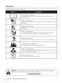 6
6
-
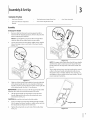 7
7
-
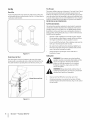 8
8
-
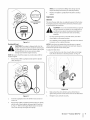 9
9
-
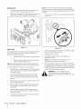 10
10
-
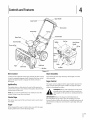 11
11
-
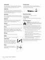 12
12
-
 13
13
-
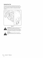 14
14
-
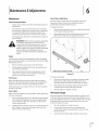 15
15
-
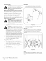 16
16
-
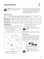 17
17
-
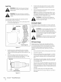 18
18
-
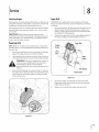 19
19
-
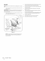 20
20
-
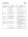 21
21
-
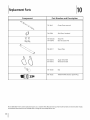 22
22
-
 23
23
-
 24
24
-
 25
25
-
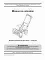 26
26
-
 27
27
-
 28
28
-
 29
29
-
 30
30
-
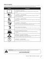 31
31
-
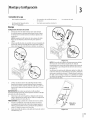 32
32
-
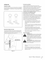 33
33
-
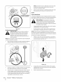 34
34
-
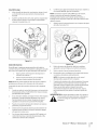 35
35
-
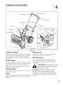 36
36
-
 37
37
-
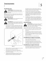 38
38
-
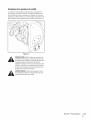 39
39
-
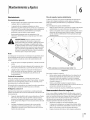 40
40
-
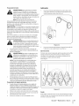 41
41
-
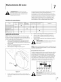 42
42
-
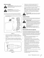 43
43
-
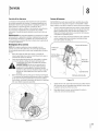 44
44
-
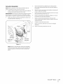 45
45
-
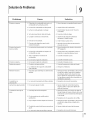 46
46
-
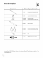 47
47
-
 48
48
-
 49
49
-
 50
50
-
 51
51
-
 52
52


MTD 31A-32AD762 El manual del propietario
- Categoría
- Lanzadores de nieve
- Tipo
- El manual del propietario
- Este manual también es adecuado para
en otros idiomas
- English: MTD 31A-32AD762 Owner's manual
Artículos relacionados
-
MTD 31A-3CAD752 El manual del propietario
-
-
-
-
-
-
-