MTD 31A-32AD700 El manual del propietario
- Categoría
- Lanzadores de nieve
- Tipo
- El manual del propietario
Este manual también es adecuado para

Safe Operation Practices • Set-Up • Operation • Maintenance • Service • Troubleshooting • Warranty
OPER roR's
L
Two-Stage Snow Thrower m 300 Series
MTD LLC, P.O. BOX 361131 CLEVELAND, OHiO 44136-0019
PrintedInUSA FormNo.769-06015
(June3,2010)

ToTheOwner
1
Thank¥ou
Thank you for purchasing a Snow Thrower manufactured by
MTD LLC. It was carefully engineered to provide excellent
performance when properly operated and maintained.
Please read this entire manual prior to operating the equipment.
It instructs you how to safely and easily set up, operate and
maintain your machine. Please be sure that you, and any other
persons who will operate the machine, carefully follow the
recommended safety practices at all times. Failure to do so could
result in personal injury or property damage.
All information in this manual is relative to the most recent
product information available at the time of printing. Review
this manual frequently to familiarize yourself with the unit, its
features and operation. Please be aware that this Operator's
Manual may cover a range of product specifications for various
models. Characteristics and features discussed and/or illustrated
in this manual may not be applicable to all models. MTD LLC
reserves the right to change product specifications, designs and
equipment without notice and without incurring obligation.
If you have any problems or questions concerning the unit,
phone your local authorized MTD service dealer or contact us
directly. MTD's Customer Support telephone numbers, website
address and mailing address can be found on this page. We want
to ensure your complete satisfaction at all times.
Throughout this manual, all references to fightand left side of the
machine are observed from the operating position
Tableof Contents
Safe Operation Practices ........................................ 3
Assembly & Set-Up .................................................. 7
Controls and Features ............................................ 10
Opera tion ................................................................ 12
Maintenance and Adjustments ............................ 13
Service ..................................................................... 15
Troubleshooting ..................................................... 17
Replacement Parts ................................................. 18
Warranty ................................................................. 21
Espanol ................................................................... 22
RecordProductinformation
Before setting up and operating your new equipment, please
locate the model plate on the equipment and record the
information in the provided area to the right. You can locate the
model plate by standing at the operator's position and looking
down at the rear of the frame. This information will be necessary,
should you seek technical support via our web site, Customer
Support Department, or with a local authorized service dealer.
MODEL NUMBER
D[31313131313131313D
SERIAL NUMBER
DD[3D[3D[3D[3DD
CustomerSupport
Please do NOT return the unit to the retailer or dealer without first contacting our Customer Support Department.
If you have difficulty assembling this product or have any questions regarding the controls, operation, or maintenance of
this unit, you can seek help from the experts. Choose from the options below:
0 Visit us on the web at www.mtdproducts.com
0 Call a Customer Support Representative at (800) 800-7310 or (330) 220-4683
0 Write us at MTD LLC • EO. Box 361131 • Cleveland, OH • 44136-0019

ImportantSafeOperationPractices
2
WARNING! This symbol points out important safety instructions which, if not followed,
could endanger the personal safety and/or property of yourself and others. Read and follow
all instructions in this manual before attempting to operate this machine. Failure to comply
with these instructions may result in personal injury.
When you see this symbol. NEED ITS WARNING!
CALIFORNIA PROPOSITION 65
WARNING! Engine Exhaust, some of its constituents, and certain vehicle components
contain or emit chemicals known to State of California to cause cancer and birth defects
or other reproductive harm.
DANGER: This machine was built to be operated according to the safe operation practices in
this manual. As with any type of power equipment, carelessness or error on the part of the
operator can result in serious injury. This machine is capable of amputating fingers, hands,
toes and feet and throwing foreign objects. Failure to observe the following safety
instructions could result in serious injury or death.
Training Preparation
1. Read, understand, and follow all instructions on the
machine and in the manual(s) before attempting to
assemble and operate. Keep this manual in a safe place for
future and regular reference and for ordering replacement
parts.
2. Be familiar with all controls and their proper operation.
Know how to stop the machine and disengage them
quickly.
3. Never allow children under 14 years of age to operate this
machine. Children 14 and over should read and understand
the instructions and safe operation practices in this manual
and on the machine and be trained and supervised by an
adult.
4. Never allow adults to operate this machine without proper
instruction.
5. Thrown objects can cause serious personal injury. Plan
your snow-throwing pattern to avoid discharge of material
toward roads, bystanders and the like.
6. Keep bystanders, pets and children at least 75 feet from the
machine while it is in operation. Stop machine if anyone
enters the area.
Exercise caution to avoid slipping or falling, especially
when operating in reverse.
Thoroughly inspect the area where the equipment is to be used.
Remove all doormats, newspapers, sleds, boards, wires and other
foreign objects, which could be tripped over or thrown by the
auger/impeller.
1. Always wear safety glasses or eye shields during operation
and while performing an adjustment or repair to protect
your eyes. Thrown objects which ricochet can cause serious
injury to the eyes.
2. Do not operate without wearing adequate winter outer
garments. Do not wear jewelry, long scarves or other loose
clothing, which could become entangled in moving parts.
Wear footwear which will improve footing on slippery
surfaces.
3. Use a grounded three-wire extension cord and receptacle
for all machines with electric start engines.
4. Adjust auger housing height to clear gravel or crushed rock
surfaces.
5. Disengage all control levers before starting the engine.
6. Never attempt to make any adjustments while engine is
running, except where specifically recommended in the
operator's manual.
7. Let engine and machine adjust to outdoor temperature
before starting to clear snow.

SafeHandlingof Gasoline
To avoid personal injury or property damage use extreme care
in handling gasoline. Gasoline is extremely flammable and the
vapors are explosive. Serious personal injury can occur when
gasoline is spilled on yourself or your clothes which can ignite.
Wash your skin and change clothes immediately.
a. Use only an approved gasoline container.
b. Extinguish all cigarettes, cigars, pipes and other
sources of ignition.
Never fuel machine indoors.
C.
d.
Never remove gas cap or add fuel while the engine is
hot or running.
e. Allow engine to cool at least two minutes before
refueling.
f. Never over fill fuel tank. Fill tank to no more than 1/2
inch below bottom of filler neck to provide space for
fuel expansion.
g. Replace gasoline cap and tighten securely.
h. If gasoline is spilled, wipe it off the engine and
equipment. Move machine to another area. Wait 5
minutes before starting the engine.
i. Never store the machine or fuel container inside
where there is an open flame, spark or pilot light
(e.g. furnace, water heater, space heater, clothes
dryer etc.).
j. Allow machine to cool at least 5 minutes before
storing.
k. Never fill containers inside a vehicle or on a truck
or trailer bed with a plastic linen Always place
containers on the ground away from your vehicle
before filling.
I. If possible, remove gas-powered equipment from
the truck or trailer and refuel it on the ground. If this
is not possible, then refuel such equipment on a
trailer with a portable container, rather than from a
gasoline dispenser nozzle.
m. Keep the nozzle in contact with the rim of the fuel
tank or container opening at all times until fueling is
complete. Do not use a nozzle lock-open device.
Operation
1. Do not put hands or feet near rotating parts, in the auger/
impeller housing or chute assembly. Contact with the
rotating parts can amputate hands and feet.
2. The auger/impeller control lever is a safety device. Never
bypass its operation. Doing so makes the machine unsafe
and may cause personal injury.
3. The control levers must operate easily in both directions
and automatically return to the disengaged position when
released.
4.
Never operate with a missing or damaged chute assembly.
Keep all safety devices in place and working.
5. Never run an engine indoors or in a poorly ventilated area.
Engine exhaust contains carbon monoxide, an odorless
and deadly gas.
6. Do not operate machine while under the influence of
alcohol or drugs.
7. Muffler and engine become hot and can cause a burn. Do
not touch. Keep children away.
8. Exercise extreme caution when operating on or crossing
gravel surfaces. Stay alert for hidden hazards or traffic.
9. Exercise caution when changing direction and while
operating on slopes.
10. Plan your snow-throwing pattern to avoid discharge
towards windows, walls, cars etc. Thus, avoiding possible
property damage or personal injury caused by a ricochet.
11. Never direct discharge at children, bystanders and pets or
allow anyone in front of the machine.
12. Do not overload machine capacity by attempting to clear
snow at too fast of a rate.
13.
14.
15.
Never operate this machine without good visibility or light.
Always be sure of your footing and keep a firm hold on the
handles. Walk, never run.
Disengage power to the auger/impeller when transporting
or not in use.
Never operate machine at high transport speeds on
slippery surfaces. Look down and behind and use care
when backing up.
16. If the machine should start to vibrate abnormally, stop
the engine, disconnect the spark plug wire and ground it
against the engine. Inspect thoroughly for damage. Repair
any damage before starting and operating.
17. Disengage all control levers and stop engine before you
leave the operating position (behind the handles). Wait
until the auger/impeller comes to acomplete stop before
unclogging the chute assembly, making any adjustments,
or inspections.
18. Never put your hand in the discharge or collector openings.
Always usethe clean-out tool provided to unclog the
discharge opening. Do not unclog chute assembly while
engine is running. Shut off engine and remain behind
handles until all moving parts have stopped before
unclogging.
19. Use only attachments and accessoriesapproved by the
manufacturer (e.g.wheel weights, tire chains, cabs etc.).
20. When starting engine, pull cord slowly until resistance
isfelt, then pull rapidly. Rapid retraction of starter cord
(kickback) will pull hand and arm toward engine faster than
you can let go. Broken bones, fractures, bruises or sprains
could result.
21.
If situations occur which are not covered in this manual, use
care and good judgment. Contact Customer Support for
assistance and the name of your nearest servicing dealer.
4 I SECTION 2 -- IMPORTANT SAFE OPERATION PRACTICES

Clearinga CloggedDischargeChute
Hand contact with the rotating impeller inside the discharge
chute is the most common cause of injury associated with snow
throwers. Never use your hand to clean out the discharge chute.
To clear the chute:
1. SHUTTHE ENGINE OFF!
2. Wait 10 seconds to be sure the impeller blades have
stopped rotating.
3. Always use a clean-out tool, not your hands.
Maintenance& Storage
1. Never tamper with safety devices. Check their proper
operation regularly. Refer to the maintenance and
adjustment sections of this manual.
2. Before cleaning, repairing, or inspecting machine
disengage all control levers and stop the engine. Wait until
the auger/impeller come to a complete stop. Disconnect
the spark plug wire and ground against the engine to
prevent unintended starting.
3. Check bolts and screws for proper tightness at frequent
intervals to keep the machine in safe working condition.
Also, visually inspect machine for any damage.
4. Do not change the engine governor setting or over-speed
the engine. The governor controls the maximum safe
operating speed of the engine.
5. Snow thrower shave plates and skid shoes are subject to
wear and damage. For your safety protection, frequently
check all components and replace with original equipment
manufacturer's (OEM) parts only. "Use of parts which do
not meet the original equipment specifications may lead to
improper performance and compromise safety!"
6. Check control levers periodically to verify they engage
and disengage properly and adjust, if necessary. Refer
to the adjustment section in this operator's manual for
instructions.
7. Maintain or replace safety and instruction labels, as
necessary.
8. Observe proper disposal laws and regulations for gas, oil,
etc. to protect the environment.
g. Prior to storing, run machine a few minutes to clear snow
from machine and prevent freeze up of auger/impeller.
10. Never store the machine or fuel container inside where
there is an open flame, spark or pilot light such as a water
heater, furnace, clothes dryer etc.
11. Always refer to the operator's manual for proper
instructions on off-season storage.
12. Check fuel line, tank, cap, and fittings frequently for cracks
or leaks. Replace if necessary.
13. Do not crank engine with spark plug removed.
14.
According to the Consumer Products Safety Commission
(CPSC) and the U.S. Environmental Protection Agency (EPA),
this product has an Average Useful Life of seven (7) years,
or 60 hours of operation. At the end of the Average Useful
Life have the machine inspected annually by an authorized
service dealer to ensure that all mechanical and safety
systems are working properly and not worn excessively.
Failure to do so can result in accidents, injuries or death.
Donot modify engine
To avoid serious injury or death, do not modify engine in any
way. Tampering with the governor setting can lead to a runaway
engine and cause it to operate at unsafe speeds. Never tamper
with factory setting of engine governor.
Notice Regarding Emissions
Engines which are certified to comply with California and federal
EPA emission regulations for SORE (Small Off Road Equipment)
are certified to operate on regular unleaded gasoline, and
may include the following emission control systems: Engine
Modification (EM), Oxidizing Catalyst (OC), Secondary Air
Injection (SAI) and Three Way Catalyst (TWC) if so equipped.
SparkArrestor
i_li WARNING! This machine is equipped with an
internal combustion engine and should not be used
on or near any unimproved forest-covered, brush
covered or grass-covered land unless the engine's
exhaust system is equipped with a spark attester
meeting applicable local or state laws (if any).
Ira spark arrester is used, it should be maintained in effective
working order by the operator. In the State of California the
above is required by law (Section 4442 of the California Public
Resources Code). Other states may have similar laws. Federal laws
apply on federal lands.
A spark attester for the muffler is available through your
nearest engine authorized service dealer or contact the service
department, RO. Box 361131 Cleveland, Ohio 44136-0019.
SECTION 2 -- IMPORTANT SAFE OPERATION PRACTICES S

Safety Symbols
This page depicts and describes safety symbols that may appear on this product. Read, understand, and follow all instructions on the
machine before attempting to assemble and operate.
READ THE OPERATOR'S MANUAL(S)
Read, understand, and follow all instructions in the manual(s) before attempting to
assemble and operate
WARNING-- ROTATING BLADES
Keep hands out of inlet and discharge openings while machine is running. There are rotating
blades inside
WARNING-- ROTATING BLADES
Keep hands out of inlet and discharge openings while machine is running. There are rotating
blades inside
WARNING-- ROTATING AUGER
Do not put hands or feet near rotating parts, in the auger/impeller housing or chute
assembly. Contact with the rotating parts can amputate hands and feet.
WARNING--THROWN OBJECTS
This machine may pick up and throw objects which can cause serious personal injury.
WARNING--GASOLINE IS FLAMMABLE
Allow the engine to cool at least two minutes before refueling.
WARNING-- CARBON MONOXIDE
Never run an engine indoors or in a poorly ventilated area. Engine exhaust contains carbon
monoxide, an odorless and deadly gas.
WARNING-- ELECTRICAL SHOCK
Do not use the engine's electric starter in the rain
WARNING-- HOT SURFACE
Engine parts, especially the muffler, become extremely hot during operation. Allow engine
and muffler to cool before touching.
WARNING! Your Responsibility--Restrict the use of this power machine to persons who read, understand and
follow the warnings and instructions in this manual and on the machine.
SAVETHESEINSTRUCTIONS[
6 I SECTION 2 -- IMPORTANT SAFE OPERATION PRACTICES

Assembly&Set-Up
3
Contentsof Carton
One Snow Thrower
One Snow Thrower Operator's
Manual
Two Replacement Auger Shear Pins
One Product Registration Card
One Engine Operator's Manual
Assembly
Setting UpTheHandle
1. Remove cable tie (if present) securing upper handle to
lower handle for shipping purposes. Remove all protective
plastic wrapping from handles.
NOTE: Be careful NOT to remove the three loosely fitted
cable ties that will be utilized later to secure cables.
2.
Loosen and remove the wing knob, saddle washer, handle
tab and carriage screw on each side of the lower handle.
See Fig. 3-1.
3.
Figure 34
Slide one of the loosely fitted cable ties from the right side
of the lower handle up to the cross member of the lower
handle. Leave the second cable tie in place on the right side
of the lower handle. See Fig. 3-3 for reference.
IMPORTANT: It will be necessary to lift the upper handle while
sliding up this cable tie to prevent damage to the cable.
4. Lift the upper handle up and position it over the lower
handle, aligning the holes where the wing knobs were
removed (1).SeeFig. 3-2.
CAUTION: Be careful not to bend or kink the cables.
5. Insert a carriage screw from the outside through a handle
tab, the upper and lower handles, a saddle washer and into
the wing knob (2). Repeat on the other side.
6. Tighten the wing knobs on each side of the handle. Refer
to Fig. 3-2.
7.
Figure 3=2
NOTE:The auger cable routes down the left lower handle
and the drive cable is routed across the top of the lower
handle and down the right side of the lower handle. See
Fig. 3-3.
Three cable ties have been used to loosely tie the control
cables to the lower handle, including the cable tie you
relocated in step 3. Position cable ties now, as in Fig. 3-3,
and tighten to secure cables to the lower handle. Trim off
excess material of cable ties.
er Cable
Figure 3=3

Set-Up
ShearPins
A pair of replacement auger shear pins and bow tie cotter pins
are included with your snow thrower. See Fig. 3-4. Store them in
a safe place until needed.
Figure 3-4
ChuteClean-0utTool
The chute clean-out tool isfastened to the top of the auger
housing with a mounting clip and acable tie at the factory. Cut
the cable tie before operating the snow thrower. See Fig.3-5.
Chute Clean=out Tool
Figure 3-5
TirePressure
_/il ARNING: Under any circumstance do not exceed
manufacturer's recommended psi. Equal tire
pressure should be maintained at all times. Excessive
pressure when seating beads may cause tire/rim
assembly to burst with force sufficient to cause
serious injury. Refer to sidewall of tire for
recommended pressure.
The tires are over-inflated for shipping purposes. Check the tire
pressure before operating the snow thrower. Refer to the tire
side wall for tire manufacturer's recommended psi and deflate
(or inflate) the tires as necessary. Use a manual pump or portable
electric tire inflator to prevent over-inflation.
NEVER USE AN AiR COMPRESSOR
Note: Equal tire pressure isto be maintained at all times for
performance purposes.
Adjustments
SkidShoe
The snow thrower skid shoes are adjusted upward at the factory
for shipping purposes. Adjust them downward, if desired, prior
to operating the snow thrower.
CAUTION : It is not recommended that you operate
this snow thrower on gravel as it can easily pick up
and throw loose gravel, causing personal injury or
damage to the snow thrower and surrounding
property.
For close snow removal on a smooth surface, raise skid
shoes higher on the auger housing.
Use a middle or lower position when the area to be cleared
is uneven, such as a gravel driveway
NOTE: If you choose to operate the snow thrower on a gravel
surface, keep the skid shoes in position for maximum clearance
between the ground and the shave plate.
CAUTION: Operating a snow thrower equipped
with steel skid shoes may result in damage to
natural stone paver surfaces (e.g.sandstone,
-- bluestone, limestone). Referto the Replacement
Parts or Attachments & Accessories sections for
information on available polymer skid shoes.
Toadjust the skid shoes:
1. Loosen the four hex nuts (two on each side) and carriage
bolts. Move skid shoes to desired position. See Fig. 3-6.
2. Make certain the entire bottom surface of skid shoe is
against the ground to avoid uneven wear on the skid shoes.
3. Retighten nuts and bolts securely.
DischargeChute
I. Loosen the wing knob on the upper chute, adjust chute
and chute control to desired operating position.
2. Tighten the wing knob on the upper chute making sure the
carriage bolt is correctly positioned. Refer to Fig. 3-7.
8 [ SECTION3 -- ASSEMBLY& SET-UP

f
l! /
/
Figure 3=6
3. While standing in the operator's position (behind the snow
thrower) engage the auger.
4. Allow the auger to remain engaged for approximately 10
seconds before releasing the auger control. Repeat this
several times.
5,
With the engine running in the FASTposition and the
auger control in the disengaged "up" position, walk to the
front of the machine.
6. Confirm that the auger has completely stopped rotating
and shows NO signs of motion.
NOTE: If the auger shows ANY signs of rotating, immediately
return to the operator's position and shut off the engine. Wait for
all moving parts to stop before adjusting the auger control cable
as follows:
7. Loosen the rear hex bolt on the cable adjustment bracket.
See Fig. 3-8.
8. Slide the cable adjustment bracket forward adding a slight
amount of slack in the auger cable.
9. Retighten the rear hex bolt.
10. Start engine and verify auger control engages and
disengages properly.
Figure 3-7
AugerControl
Periodic adjustment to the auger control cable may be required
due to normal stretch and wear on the belt. Adjustment is
needed immediately if the augers:
a. Continue to turn with the auger control disengaged, or
b. During operation, augers seem to hesitate turning
while the engine maintains speed.
NOTE: Perform the following test before operating the snow
thrower for the first time and at the start of each winter season.
Check the adjustment of the auger control as follows:
1. When the auger control is released and in the disengaged
"up" position, the cable should have very little slack, but
should NOT be tight.
2. In a well-ventilated area, start the snow thrower engine.
Refer to Starting The Engine in the Operation section of the
engine operator's manual, included with the snow thrower.
Make sure the throttle is set in the FAST position.
Figure 3=8
NOTE: If auger continues to rotate with the control
disengaged, shut off engine and readjust.
11. If during operation, augers seem to hesitate turning while
the engine maintains speed, then the cable is too loose and
the bracket needs to be adjusted rearward, decreasing the
amount of slack to the auger cable. Follow the above steps
to adjust the cable adjustment bracket.
WARNING! Do not over-tighten the cable.
Overtightening may prevent the auger from
disengaging and compromise the safety of the snow
thrower.
SECTION 3 -- ASSEMBLY& SET-UP 9

ControlsandFeatures
4
Auger
S UpperHandle
StarterRope
Gasoline Cap
Drive
Control
Upper Chute
Chute Assembly
Clean-outTool
Handle
Auger ShavePlate
ChuteKnob
SkidShoe
Snow thrower controls and features are described below and
illustrated in Fig. 4-1.
Drive Control
Located on the underside of the upper handle, the drive control
is used to engage/disengage wheels. Squeeze the drive control
against the upper handle to engage the wheels; release to
disengage.
Starter Rope
The starter rope is part of the recoil starter and is used to start
the engine.
Auger
When engaged, the auger's rotation draw snow into the auger
housing and throws it out the discharge chute.
ChuteAssembly
Snow drawn into the auger housing is discharged out of the
chute assembly
J
Figure 4-1
AugerControl
The auger control is adjacent to the upper handle. Squeeze the
auger control against the upper handle to engage the augers;
release to disengage the augers.
iMPORTANT: Referto the Auger Control information in
the Assembly & Set-Up section prior to operating your snow
thrower. Readand follow all instructions carefully and perform all
adjustments to verify your snow thrower isoperating safely and
properly.
ChuteHandle
The direction of snow throwing corresponds to the direction
of the chute opening. Use the chute handle to turn the chute
assembly in the direction you wish to throw the snow.
ChuteKnob
The distance snow isthrown can be adjusted by either raising
or lowering the upper chute. Loosen the chute knob on the side
of the upper chute to adjust. Pivot the upper chute to desired
position, and retighten the chute knob.

ShavePlate
The shave plate maintains contact with pavement as the snow
thrower is propelled, allowing snow close to pavement's surface
to be discharged.
SkidShoes
Position the skid shoes based on surface conditions. Adjust
upward for hard-packed snow. Adjust downward when
operating on gravel or crushed rock surfaces.
ChuteAssembly
Snow drawn into the auger housing is discharged out the chute
assembly.
ChuteClean-OutTool
i_ WARNING! Never use your hands to clear a
clogged chute assembly. Shut off engine and remain
behind handles until all moving parts have stopped
before unclogging.
The chute clean-out tool is conveniently fastened to the rear of
the auger housing with a mounting clip. Should snow and ice
become lodged in the chute assembly during operation, proceed
as follows to safely clean the chute assembly and chute opening:
1. Release both the Auger Control and the Drive Control.
2. Shut off engine as instructed in the engine manual.
3. Remove the clean-out tool from the clip which secures it to
the rear of the auger housing.
4. Use the shovel-shaped end of the clean-out tool to
dislodge and scoop any snow and ice which has formed in
and near the chute assembly.
5. Refasten the clean-out tool to the mounting clip on the
rear of the auger housing, start the snow thrower's engine
as instructed in the engine manual.
While standing in the operator's position (behind the snow
thrower), engage the auger control for a few seconds to clear any
remaining snow and ice from the chute assembly.
SECTION 4 -- CONTROLS AND FEATURES 11

Operation
Starting TheEngine
Refer to the Operation section of the engine operator's manual
included with the snow thrower.
1"oEngageDrive
2.
Move the throttle control into the Fast (rabbit) position.
To engage the drive, squeeze the drive control completely
against the upper handle to engage the wheels. To stop
the forward motion, release the drive control.
ToEngageAugers
1. To engage the augers, squeeze the auger control handle
completely against the upper handle. To stop the augers,
release handle.
ReplacingShearPins
The augers are secured to the spiral shaft with two shear pins
and cotter pins. If the auger should strike a foreign object or ice
jam, the snow thrower is designed so that the pins may shear. If
the augers will not turn, check to see if the pins have sheared.
See Fig. 5-1.
_ AUTION: NEVER replace the auger shear pins with
anything other than OEM Part No. 738-04124A
replacement shear pins. Any damage to the auger
gearbox or other components as a result of failing to
do so will NOT be covered by your snow thrower's
warranty.
_ WARNING! Always turn off the snow thrower's
engine, as instructed in the engine owner's manual
and remove the key prior to replacing shear pins.
Figure S=I

Maintenance&Adjustments
Maintenance
GeneralRecommendations
Always observe safety rules when performing any type of
maintenance.
The warranty on this snow thrower does not cover items
that have been subjected to operator abuse or negligence.
To receive full value from the warranty, operator must
maintain the snow thrower as instructed in this manual.
Periodically check all fasteners and hardware to make sure
these are tight.
ill_i WARNING! Before servicing, repairing, lubricating,
or inspecting, disengage all controls and stop
engine. Wait until all moving parts have come to a
complete stop. Disconnect spark plug wire and
ground it against the engine to prevent unintended
starting. Always wear safety glasses during
operation or while _erforming any adjustments or
repairs.
Engine
IMPORTANT: Refer to the engine operator's manual included
with the snow thrower for complete oil servicing instructions.
TirePressure
Before operating, check tire pressure and reduce pressure to
between 15 psi and 20 psi. Refer to Setup in the Assembly and
Setup section of this manual for proper filling procedures.
If the tire pressure is not equal in both tires, the unit may pull to
one side or the other.
CheckV-Belts
Follow instructions below to check condition of drive belts every
S0 hours of operation.
1. Remove the plastic belt cover on the front of the engine by
removing the self-tapping screw and pressing the plastic
tabs to release the belt cover. See Fig. 7-1 in the Service
section of this manual.
2_
Visually inspect for frayed, cracked, or excessively worn out
belts. Replace, if necessary, following instructions in the
Service section of this manual.
ShavePlateand SkidShoes
The shave plate and skid shoes on the bottom of the snow
thrower are subject to wear. These should be checked
periodically and replaced when necessary.
To replace skid shoes:
1. Remove the carriage bolts and nuts securing each skid shoe
to the auger housing, See Fig. 6-1.
2. Reassemble new skid shoes with hardware just removed.
Make sure the skid shoes are adjusted to be level.
f
jJJJ ii
\
/
/
_Note: Augers not shown for clarity.
J
Figure 6-1
To remove shave plate:
3. Remove both skid shoes and hardware including carriage
bolts and nuts which attach shave plate to the snow
thrower housing. For location of shave plate, see Fig. 6-1.
4. Reassemble new shave plate, making sure heads of the
carriage bolts are to the inside of the housing.
5. Reinstall skid shoes. Tighten securely.
Off-SeasonStorage
If the snow thrower will not be used for 30 days or longer, or if it
is the end of the snow season when the last possibility of snow is
gone, the equipment needs to be stored properly. Follow storage
instructions below to ensure top performance from the snow
thrower for many more years.
1. Store the equipment in a clean, dry area.
2. If storing the snow thrower in an unventilated area,
rustproof the machine using a light oil or silicone to coat
the snow thrower.
3. Clean the exterior of the engine and the snow thrower.
13

Preparing TheEngine
IMPORTANT: Referto the engine operator's manual
included with the snow thrower for complete engine servicing
instructions.
WARNING! Never store the snow thrower with fuel
in the tank indoors or in poorly ventilated areas,
where fuel fumes may reach an open flame, spark or
pilot light ason afurnace, water heater, clothes
dryer orgas appliance.
PreparingTheSnowThrower
1. When storing the snow thrower in an unventilated or
metal storage shed,care should be taken to rustproof the
equipment. Using alight oil or silicone, coat the equipment,
especially any chains,springs, bearings and cables.
2. Remove all dirt from exterior of engine and equipment.
3. Follow lubrication recommendations in the Maintenance
section of this manual.
4. Store equipment in a clean, dry area.
Lubrication
1. Lubricate pivot points on the auger control and drive
control with a light engine oil once aseason, see Fig.6-2.
2. Lubricate the auger idler bracket with a light engine oil
once a season. See Fig.6-2.
f
/ /
AugerShaft
At least once a season, remove the shear pins from the auger
shaft. Spray lubricant inside the shaft and around the spacers and
the flange bearings found at either end of the shaft.
See Fig.6-3.
_" :/-117-
I O_ro _o S
I
k
Figure 6-3
J
Wheels
At least once a season, remove both wheels. Clean and coat the
axles with a multipurpose automotive grease before reinstalling
wheels.
J
Figure 6-2
SECTION 6-- MAINTENANCE & ADJUSTMENTS

Service
7
The augers are secured to the spiral shaft with four shear pins and
cotter pins. If you hit a foreign object or ice jam, the snow thrower
is designed so that the pins may shear. Refer to Fig. 5-1.
If the augers do not turn, check if the pins have sheared. Replace,
if needed, with proper shear pins. Refer to Parts List for correct
part number.
CAUTION: NEVERreplace the auger shear pins with
standard pins or fasteners. Any damage to the auger
gearbox or other components, asa result of doing
so,will NOT be covered byyour snow thrower's
warranty.
ReplacingBelts
1. Allow the engine to run until it is out of fuel. Do not
attempt to pour fuel from the engine
2. Remove the key to prevent accidental starting.
3. Remove the self-tapping screw shown in Fig. 7-1, and press
the plastic tabs to release the belt coven Pull the belt cover
up and out from around the engine and chute assembly.
Set it aside and save.
Auger Belt
1. Tip the snow thrower up and forward so that it rests on
the auger housing. Remove the belt keeper (Refer to Fig.
7-3). Return the snow thrower to its upright position to
complete the following steps.
2. Slip the front auger belt off of the engine pulley, pushing it
forward and rolling in off of the pulley. See Fig. 7-2.
Auger Belt
\
Belt Keeper
Idler Bracket
Figure 7-2
3. Squeeze the auger control handle to release the auger
brake, which is the tab that holds the belt onto the auger
pulley. Remove the belt.
4. Replace with new belt after replacing the drive belt.
J
Figure 7-1
15

DriveBelt
NOTE:Replace the drive belt before reassembling the new auger
belt.
1.
2.
Tip the snow thrower up and forward so that it rests on the
auger housing.
Remove the spring that connects the transmission to a bolt
on the engine frame. See Fig. 7-3.
NOTE: It may be easier to first remove the flange lock nut,
then use needle-nosed pliers to firmly grip spring and
remove from bolt.
Spring
Belt Kee
Figure 7-3
3.
4.
5.
6.
7.
8.
9.
10.
Pivot the transmission forward to release pressure on the
drive belt. Remove belt from transmission pulley.
Remove the drive belt from around the engine pulley, and
away from the unit.
Place the new drive belt on the engine pulley. See Fig. 7-2.
Tilt the transmission forward and position the drive belt
onto the transmission pulley.
Reconnect the spring to the bolt on the engine frame and
secure the transmission. Reinstall the flange lock nut.
Install new auger belt.
Reassemble the belt cover on the snow thrower
Reassemble the belt keeper to the housing.
SECTION7-- SERVICE

Troubleshooting
Problem
Unit fails to self-propel
Unit fails to discharge snow
Cause
I
1. Drive belt loose ordamaged.
1. Chute assembly clogged.
2. Shear pin(s) sheared.
3. Foreign object lodged in auger.
4. Auger control cable out of adjustment.
S. Auger belt loose or damaged.
Remedy
1. Replace drive belt.
1. Stop engine and disconnect spark plug wire.
Clean chute and inside of auger housing with
clean-out tool or stick.
2. Replace shear pin(s).
3. Stop engine immediately and disconnect the
spark plug wire. Remove object from auger.
4. Adjust auger control cable.
5. Replace auger belt.
IMPORTANT: Refer to the engine operator's manual included with the snow thrower for engine troubleshooting instructions.
NOTE: For repairs beyond the minor adjustments listed above, contact your nearest authorized service representative or call 1-800-800-7310
for the Customer Support Center. Refer to the engine manual packed separately with your snow thrower, for complete engine related
information.
17

ReplacementParts
9
Component l Part Number and Description
954-04014 Auger Drive Belt
954-04013 Wheel Drive Belt
738-04124A
714-04040
784-5580
731-06439
731-2643
Shear Pin, 1.50
Bow-tie Cotter Pin
Skid Shoe, Standard (steel)
Skid Shoe, Standard (Polymer)
Chute Clean-out Tool
790-00117 Shave Plate, 22"
Phone (800) 800-7310 to order replacement parts or a complete Parts Manual (have your full model number and serial number ready).
Parts Manual downloads are also available free of charge at www.mtdproducts.com.

MTD CONSUMER GROUP INC (MTD), the California Air Resources Board (CARB)
and the United States Environment Protection Agency (U. S. EPA)
Emission Control System Warranty Statement
(Owner's Defect Warranty Rights and Obligations)
EMISSIONCONTROLSYSTEMCOVERAGEISAPPLICABLETOCERTIFIEDENGINESPURCHASEDINCALIFORNIAIN2005ANDTHERE-
AFTER,WHICHAREUSEDINCALIFORNIA,ANDTOCERTIFIEDMODELYEAR2005ANDLATERENGINESWHICHAREPURCHASEDAND
USEDELSEWHEREINTHEUNITEDSTATES.
Californiaandelsewherein theUnitedStatesEmissionControlDefectsWarrantyCoverage
TheCaliforniaAirResourcesBoard(CARB),U.S.EPAandMTDarepleasedtoexplaintheemissionscontrolsystemwarrantyonyourmodelyear
2006andlatersmalloff-roadengine.InCalifornia,newsmalloff-roadenginesmustbe designed,builtandequippedtomeettheStatesanti-smog
standards.ElsewhereintheUnitedStates,newnon-road,spark-ignitionenginescertifiedformodel2005and later,mustmeetsimilarstandardsset
forthbytheU.S.EPA.MTDmustwarrantytheemissioncontrolsystemonyourenginefortheperiodoftimelistedbelow,providedtherehasbeen
noabuse,neglector impropermaintenanceofyoursmalloff-roadengine.
Youremissioncontrolsystemmayincludepartssuchasthecarburetor,fuel-injectionsystem,theignitionsystem,andcatalyticconverter,fueltanks,
fuellines,fuelcaps,valves,canisters,filters,vaporhoses,clamps,connectors,andotherassociatedemission-relatedcomponents.
Wherea warrantableconditionexists,MTDwillrepairyoursmalloff-roadengineat nocosttoyourincludingdiagnosis,partsand labor.
MANUFACTURER'S WARRANTY COVERAGE:
Thisemissionscontrolsystemiswarrantedfortwoyears.If anyemission-relatedpartonyourengineisdefective,thepartwillberepairedor
replacedbyMTD.
OWNER'S WARRANTY RESPONSIBILITIES:
Asthesmalloff-roadengineowner,youare responsibleforthe performanceofthe requiredmaintenancelistedinyourOwner'sManual.MTD
recommendsthatyouretainall yourreceiptscoveringmaintenanceson yoursmalloff-roadengine,butMTDcannotdenywarrantysolelyforthe
lackofreceiptsor foryourfailureto ensuretheperformancetoallscheduledmaintenance.
Asthesmalloff-roadengineowner,youshouldhoweverbeawarethat MTDmaydenyyourwarrantycoverageifyoursmalloff-roadengineorpart
hasfaileddue toabuse,neglect,impropermaintenanceor unapprovedmodifications.
Youare responsibleforpresentingyoursmalloff-roadenginetoan AuthorizedMTDServiceDealerassoonasa problemexists.Thewarranted
repairsshouldbe completedina reasonableamountof time,nottoexceed30 days.
Ifyouhaveanyquestionsregardingyourwarrantyrightsand responsibilities,youshouldcontacta MTDServiceRepresentativeat 1-800-800-7310
andaddressisMTDCONSUMERGROUP,RO.Box361131,ClevelandOH,44136-0019.
DEFECTS WARRANTY REQUIREMENTS FOR 1995 AND LATER SMALL OFF-ROAD ENGINES:
Thissectionappliesto 1995andlatersmalloff-roadengines.Thewarrantyperiodbeginsonthedatetheengineor equipmentisdeliveredtoan
ultimatepurchaser.
(a) GeneralEmissionsWarrantyCoverage
MTDmustwarranttotheultimatepurchaserandeachsubsequentpurchaserthattheengineis:
(1)Designed,built,andequippedsoasto conformwithallapplicableregulationsadoptedbytheAirResourcesBoardpursuantto itsauthorityin
Chapters1and2,Part5,Division26of theHealthandSafetyCode;and
(2) Freefromdefectsin materialsandworkmanshipthatcausethefailureofa warrantedparttobeidenticalinall materialrespectstothepartas
describedin theenginemanufacturer'sapplicationforcertificationfora periodoftwoyears.
(b)Thewarrantyonemissions-relatedpartswillbe interpretedasfollows:
(1)Anywarrantedpartthatisnotscheduledforreplacementas requiredmaintenanceinthewritteninstructionsrequiredbySubsection(c)
mustbewarrantedforthewarrantyperioddefinedinSubsection(a)(2).Ifanysuchpartfailsduringtheperiodof warrantycoverage,it mustbe
repairedor replacedbyMTDaccordingto Subsection(4)below.Anysuchpartrepairedor replacedunderthewarrantymustbewarrantedfor
theremainingwarrantyperiod.
(2)Anywarrantedpartthatisscheduledonlyfor regularinspectioninthewritteninstructionsrequiredbySubsection(c)mustbewarrantedfor
thewarrantyperioddefinedin Subsection(a)(2).A statementinsuchwritteninstructionstotheeffectof"repairor replaceasnecessary"will
notreducetheperiodofwarrantycoverage.Anysuchpartrepairedor replacedunderwarrantymustbe warrantedfortheremainingwarranty
period.
(3) Anywarrantedpartthatwhichisscheduledfor replacementas requiredmaintenancein thewritteninstructionsrequiredbySubsection(c)
mustbewarrantedfortheperiodd timepriortothefirstscheduledreplacementpointforthat part.Ifthepartfailspriorto thefirstscheduled
replacement,thepartmustbe repairedor replacedbyMTDaccordingtoSubsection(4) below.Anysuchpart repairedorreplacedunder
warrantymustbewarrantedfortheremainderoftheperiodpriortothefirstscheduledreplacementpointforthepart.

(4)Repairorreplacementofanywarrantedpartunderthewarrantyprovisionsofthisarticlemustbeperformedatnochargetotheownerata
warrantystation.
(5)NotwithstandingtheprovisionsofSubsection(4)above,warrantyservicesorrepairsmustbeprovidedatallMTDdistributioncentersthat
arefranchisedtoservicethesubjectengines.
(6)Theownermustnotbechargedfordiagnosticlaborthatleadstothedeterminationthatawarrantedpartisinfactdefective,providedthat
suchdiagnosticworkisperformedatawarrantystation.
(7)Theenginemanufacturerisliablefordamagestootherenginecomponentsproximatelycausedbyafailureunderwarrantyofanywarranted
part.
(8)Throughouttheengine'swarrantyperioddefinedinSubsection(a)(2),MTDwillmaintainasupplyofwarrantedpartssufficienttomeetthe
expecteddemandforsuchparts.
(9)Anyreplacementpartmaybeusedintheperformanceofanywarrantymaintenanceorrepairsandmustbeprovidedwithoutchargetothe
owner.SuchusewillnotreducethewarrantyobligationsofMTD.
(10)Add-onormodifiedpartsthatarenotexemptedbytheAirResourcesBoardmaynotbeused.Theuseofanynon-exemptedadd-onor
modifiedpartsshallbegroundsfordisallowingawarrantyclaimmadeinaccordancewiththisarticle.Theenginemanufacturershallnotbe
liableunderthisarticletowarrantfailuresofwarrantedpartscausedbytheuseofnon-exemptedadd-onormodifiedpart.
(c)MTDwillincludea copyofthefollowingemissionwarrantypartslistwitheachnewengine,usingthoseportionsofthelistapplicabletothe
e__&gine.
(1)FuelMeteringSystem
•Coldstartenrichmentsystem(softchoke)
,,Carburetorandinternalparts
•FuelPump
•FuelTank
(2)Air InductionSystem
•Aircleaner
•Intakemanifold
(3) IgnitionSystem
•Sparkplug(s)
•MagnetoIgnitionSystem
(4)ExhaustSystem
Catalyticconverter
•SAI(Reedvalve)
(5) MiscellaneousItemsUsedin AboveSystem
Vacuum,temperature,position,timesensitivevalvesand switches
Connectorsandassemblies
(6) Evaporativecontrol
•FuelHosecertifiedforARBevaporativeemissionof2006.
•FuelHoseClamps
Tetheredfuelcap
Carboncanister
Vaporlines
GD0C-100174Rev.B

MANUFACTURER'S LiMiTED WARRANTY FOR
The limited warranty set forth below is given by MTD LLCwith
respect to new merchandise purchased and used in the United States
and/or its territories and possessions, and by MTD Products Limited
with respectto new merchandise purchased and used in Canadaand/
or its territories and possessions (either entity respectively, "MTD").
"MTD" warrants this product (excluding its Normal WearParts and
Attachments as described below) against defects in material and
workmanship for a period of two (2) years commencing onthe date
of original purchase and will, at its option, repair or replace,free of
charge, any part found to be defective in materials or workmanship.
This limited warranty shall only apply if this product has been
operated and maintained inaccordance with the Operator's Manual
furnished with the product, and has not beensubject to misuse,
abuse, commercial use, neglect, accident, improper maintenance,
alteration, vandalism, theft, fire, water, or damage because of other
peril or natural disaster. Damage resulting from the installation or use
of any part, accessory or attachment not approved by MTD for use
with the product(s) covered bythis manual will void your warranty as
to any resulting damage.
Normal WearPartsarewarranted to befree from defects in material
andworkmanship for a period of thirty (30) days from the dateof
purchase. Normal wear parts include, but are not limited to items
such as: batteries, belts, blades, bladeadapters, tines, grass bags,
wheels, rider deck wheels, seats, snow thrower skid shoes,friction
wheels, shaveplates, auger spiral rubber, engine oil, air filters, spark
plugs andtires.
Attachments-- MTD warrants attachments for this product against
defects in material and workmanship for a period of one (1) year,
commencing on the date of the attachment's original purchase or
lease.Attachments include, but are not limited to items such as:
grass collectors and mulch kits.
HOWTO OBTAINSERVICE:Warranty service is available, WITH
PROOFOFPURCHASE,through your local authorized service dealer.
Tolocate the dealer inyour area:
In the U.S.A.
Checkyour Yellow Pages,or contact MTD LLC at RO. Box 361131,
Cleveland, Ohio 44136-0019, or call 1-800-800-7310, 1-330-220-
4683 or log on to our Web site at www.mtdproducts.com.
In Canada
Contact MTDProducts Limited, Kitchener, ON N2G4J1, or call 1-800-
668-1238 or log on to our Web site atwww.mtdcanada.com.
This limited warranty does not provide coverage in the following
cases:
a.
b.
Log splitter pumps, valves, and cylinders havea separate one-
yearwarranty.
Routine maintenance items such as lubricants, filters, blade
sharpening, tune-ups, brake adjustments, clutch adjustments,
deck adjustments, and normal deterioration of the exterior finish
dueto use or exposure.
c. Service completed by someone other than an authorized service
dealer.
d. MTD does not extend any warranty for products sold or exported
outside of the United States and/or Canada,and their respective
possessions and territories, except those sold through MTD's
authorized channels of export distribution.
e. Replacement parts that are not genuine MTD parts.
f. Transportation charges and service calls.
g. MTD does not warrant this product for commercial use.
No implied warranty, including any implied warranty of
merchantability or fitness for a particular purpose,applies after
the applicable periodofexpress written warranty above as to the
parts as identified. No other express warranty, whether written or
oral, except as mentioned above, given by any personor entity,
includinga dealer or retailer, with respect to any product,shall
bind MTD. Duringthe periodof the warranty, the exclusive remedy
is repair or replacement of the productasset forth above.
The provisionsas set forth inthis warranty providethe sole and
exclusive remedy arising from the sale. MTD shall not be liable
for incidental orconsequential loss or damage including, without
limitation, expenses incurred for substitute or replacement lawn
careservices or for rental expenses to temporarily replace a
warranted product.
Some states do not allow the exclusion or limitation of incidental
or consequential damages, or limitations on how long an implied
warranty lasts, so the above exclusions or limitations may not apply
to you.
In no eventshall recovery of any kind begreater than the amount of
the purchase price of the product sold. Alteration of safety features of
the product shall void this warranty. You assume the risk and liability
for loss, damage, or injury to you and your property and/or to others
andtheir property arising out of the misuse or inability to use the
product.
This limited warranty shall not extend to anyone other than the
original purchaser or to the person for whom it was purchased as a
gift.
HOWSTATELAW RELATESTOTHISWARRANTY: This limited
warranty givesyou specific legal rights, and you may also haveother
rights which vary from stateto state.
IMPORTANT:Owner must present Original Proof of Purchase to
obtain warranty coverage.
MTD LLC, P.O. BOX 361131 CLEVELAND, OHIO 44136-0019; Phone: 1=800=800=7310, 1=330=220-4683
MTD Canada Limited - KITCHENER, ON N2G 4J1; Phone 1-800-668-1238
GDOC-100016REV. B

Medidas importantes de seguridad • Configuraci6n • Funcionamiento • Mantenimiento • Servicio •
Soluci6n de problemas • Garantia
ANUAL EL
M_quina quitanieve de dos etapas m Serie 300
MTD LLC, P.O. BOX 361131 CLEVELAND, OHiO 44136-0019
ImpresoenEstadosUnidosdeAm_rka

A!propietario
1
Gracias
Gracias por comprar una m_quina quitanieve fabricada por MTD
LLC. La misma ha sido diseffada cuidadosamente para brindar
excelente rendimiento si se la opera y mantiene correctamente.
Pot favor lea todo este manual antes de operar el equipo.
Le indica c6mo configurar, operar y mantener la m_quina
con seguridad y f_cilmente. Pot favor asegurese de seguir
cuidadosamente yen todo momento las pr_cticas de seguridad
recomendadas, y hac_rselas seguir a cualquier otra persona que
opere la m_quina. En caso de no hacerlo podrian producirse
lesiones personales o dahos materiales.
Toda la informaci6n contenida en este manual hace referencia
a la m_s reciente informaci6n de producto disponible en el
momento de la impresi6n. Revise el manual frecuentemente
para familiarizarse con la unidad, sus caracteristicas y
funcionamiento. Pot favor tenga en cuenta que este Manual
del Operador puede cubrir una gama de especificaciones de
productos de diferentes modelos. Las caracteristicas y funciones
incluidas y/o ilustradas en este manual pueden no set aplicables
a todos los modelos. MTD LLC se reserva el derecho de modificar
las especificaciones de los productos, los diseffos y el equipo
est_ndar sin previo aviso y sin generar responsabilidad pot
obligaciones de ningun tipo.
Si tienealgun problema o duda respecto a la unidad, Ilamea un
distribuidor de servicio MTD autorizado o p6ngase en contacto
directamente con nosotros. Los numeros de tel_fono, direcci6n
del sitio web y direcci6n postal de la Asistencia al Cliente de MTD
se encuentran en esta p_gina. Queremos garantizar su entera
satisfacci6n en todo momento.
En este manual, las referencias al lado derecho o izquierdo de la
m_quina se observan desde la posici6n del operador.
indice
Importante Medidas importantes de seguridad 24
Ensamblado y Conf_guraci6n ............................... 28
Controles y Caractefisticas .................................... 31
Funcionamiento .................................................... 33
Mantenimiento y Ajustes ...................................... 34
Servicio ................................................................... 36
Soluci6n de Problemas ......................................... 38
Repuestos ............................................................... 39
Garantia ......................................... Cubierta Trasera
Registrode informaci6ndeproducto
Antes de configurar y operar su equipo nuevo, por favor Iocalice
la placa del modelo en el equipo y registre la informaci6n en
el _rea situada a la derecha. Para encontrar la placa de modelo,
col6quese detr_s de la unidad en la posici6n del operador y mire
hacia la parte inferior de la secci6n trasera del chasis. Si tiene
que solicitar soporte t6cnico a trav6s de nuestro sitio web, el
Departamento de Asistencia al Cliente, o de un distribuidor de
servicio autorizado local, necesitar_ esta informaci6n.
_OMERO DE MODELO
DDDDDDDDDDD
NOMERO DE SERIE
DDDDDDDDDDD
Asistenciaal Ciiente
Por favor, NO devuelva la unidad al minorista o distribuidor sin ponerse en contacto primero con el Departamento de
Asistencia al Cliente.
En caso de tener problemas para montar este producto o de tenet dudas con respecto a los controles, fundonamiento o
mantenimiento del mismo, puede solicitar la ayuda de expertos. Elija entre las opciones que se presentan a continuaci6n:
0 Visite nuestro sitio web en www.mtdproducts.com
0 Llame a un representante de Asistencia al Cliente al (800) 800-7310 6 (330) 220-4683
0 Escrfbanos a MTD LLC • P.O. Box 361131 • Cleveland, OH • 44136-0019

Medidasimportantes deseguridad
2
iADVERTENCIA! La presencia de este s[mbolo indica que se trata de instrucciones
importantes de seguridad que se deben respetar para evitar poner en peligro su seguridad
personal y/o material y la de otras personas. Lea y siga todas las instrucciones de este manual
antes de poner en funcionamiento esta m_quina. Si no respeta estas instrucdones puede
provocar lesiones personales.
Cuando vea este s[mbolo, iTENGA EN CUENTAS LAS ADVERTENCIAS!
PROPOSICION 6S DE CALIFORNIA
iADVERTENCIA! El escape del motor de este producto, algunos de sus componentes y
algunos componentes del vehkulo contienen o liberan sustancias qu[micas que el estado
de California considera que pueden producir c_ncer, defectos de nadmiento u otros
problemas reproductivos.
PELIGRO: Esta m_quina est_ diseEada para set utilizada respetando las normas de seguridad
contenidas en este manual. AI igual que con cualquier tipo de equipo motorizado, un
descuido o error por parte del operador puede producir lesiones graves. Esta m_quina es
capaz de amputar dedos, manos y pies y de arrojar objetos extraEos con gran fuerza. De no
respetar las instrucdones de seguridad siguientes se pueden producir lesiones graves o la
muerte.
Capadtad6n 7.
1. Lea, entienda y cumpla todas las instrucciones incluidas en
la m_quina y en los manuales antes de montarla y utilizarla.
Guarde este manual en un lugar seguro para consultas
futuras y peri6dicas, asi como para solicitar repuestos.
2. Familiaricese con todos los controles y con el uso adecuado
de los mismos. Sepa c6mo detener la m_quina y desactivar
los controles r_pidamente.
3. No permita nunca que los niEos menores de 14aEos
utilicen esta m_quina. Los niEos de 14 ahos en adelante
deben leery entender las instrucciones de operaci6n y
normas de seguridad contenidas en este manual, y en la
m_quina ydeben set entrenados y supervisados pot un
adulto.
4.
5.
Nunca permita que los adultos operen esta m_quina sin
recibir antes la instruccidn apropiada.
Los objetos arrojados por la m_quina pueden producir
lesiones graves. Planifique el patrdn en el queva air
arrojando nieve para evitar que la descarga de material se
realice hacia los caminos, los observadores, etc.
6.
Mantenga a los observadores, ayudantes, mascotas y ni_os
por Io menosa 75 pies de la m_quina mientras la misma
est_ en funcionamiento. Detenga la m_quina si alguien se
acerca.
Sea precavido para evitar patinarse o caerse especialmente
cuando opera la m_quina en reversa.
Preparativos
Inspeccione minuciosamente el _rea donde utilizar_ el equipo.
Saque todos los felpudos, peri6dicos, trineos, tablas, cables y
otros objetos extrahos con los que podria tropezar o que podrian
set arrojados pot la barrena / impulsor.
1. Para protegerse los ojos utilice siempre anteojos o
antiparras de seguridad mientras opera la m_quina o
mientras la ajusta o repara. Los objetos arrojados que
rebotan pueden producir lesiones oculares graves.
2. No opere la m_quina sin la vestimenta adecuada para
estar al aire libre en invierno. No utilice alhajas, bufandas
largas u otras prendas sueltas que podrian enredarse en las
partes m6viles. Utilice un calzado especial para superficies
resbaladizas.
3.
Use un prolongador y un tomacorriente de tres cables con
conexi6n a tierra para todas las m_quinas con motores de
encendido el6ctrico.
4. Ajuste la altura de la caja del tomacorriente para limpiar la
grava o las superficies con piedras trituradas.
S. Desengrane todas las palancas de control antes de arrancar
el motor.

6. Nuncaintenterealizarajustesmientraselmotorest,1
enmarchaexceptoenloscasosespecificamente
recomendadosenelmanualdeloperador.
7. Dejequeelmotorylam_iquinaseadaptenala
temperaturaexteriorantesdecomenzarasacarlanieve.
Manejosegur0de la gasolina
Para evitar lesiones personales o dahos materiales tenga mucho
cuidado cuando trabaje con gasolina. La gasolina es sumamente
inflamable y sus vapores pueden causar explosiones. Si se
derrama gasolina encima o sobre la ropa se puede lesionar
gravemente ya que se puede incendiar. L_ivese la piel y c_imbiese
de ropa de inmediato.
a. Utilice s61o los recipientes para gasolina autorizados.
b. Apague todos los cigarrillos, cigarros, pipas y otras
fuentes de combusti6n.
c. Nunca cargue combustible en la m_iquina en un
espacio cerrado.
d. Nunca saque la tapa del combustible ni agregue
combustible mientras el motor est,1 caliente o en
ma rcha.
e. Deje que el motor se enfrie pot Io menos dos
minutos antes de volver a cargar combustible.
fl Nunca Ilene en exceso el dep6sito de combustible.
Llene el tanque a no m_is de 1/2pulgada pot debajo
de la base del cuello de Ilenado dejando espacio
para la dilataci6n del combustible.
g. Vuelva a colocar la tapa de la gasolina y ajustela
bien.
h. Limpie el combustible que se haya derramado sobre
el motor y el equipo. Traslade la m_iquina a otra
zona. Espere 5 minutos antes de encender el motor.
i. Nunca almacene la m_iquina o el recipiente de
combustible en un espacio cerrado donde haya
fuego, chispas o luz piloto (pot ejemplo, hornos,
calentadores de agua, calefactores, secadores de
ropa, etc.).
j. Deje que la m_iquina se enfrie por Io menos 5
minutos antes de guardarla.
k. Nunca Ilene los recipientes en el interior de
un vehiculo o cami6n o caja de remolque con
recubrimientos pl_isticos. Coloque siempre los
recipientes en el piso y lejos del vehiculo antes de
Ilenarlos.
I. Si es posible, retire el equipo a gasolina del cami6n o
remolque y II_nelo en el suelo. Si esto no es posible,
Ilene el equipo en un remolque con contenedor
port_itil, en vez de desde una boquilla dispensadora
de gasolina.
m. Mantenga la boquilla dispensadora en contacto
con el borde del dep6sito de combustible o con la
abertura del recipiente en todo momento, hasta
terminar la carga. No utilice un dispositivo de
apertura/cierre de boquilla.
Funcionamiento
No ponga las manos o los pies cerca de las piezas
rotatorias, en la caja de la barrena / impulsor o en el
montaje del canal de descarga. Hacer contacto con piezas
giratorias puede resultar en la amputaci6n de manos o
pies.
2. La palanca de control de la barrena / impulsor es un
dispositivo de seguridad. Nunca evite su funcionamiento.
De hacerlo la operaci6n de la m_iquina es riesgosa y puede
ocasionar lesiones.
3. Las palancas de control deben funcionar bien en ambas
direcciones y regresar autom_iticamente a la posici6n de
desengrane cuando se las suelta.
4. Nunca opere la m_iquina si falta un montaje del canal o si
el mismo est,1 dahado. Mantenga todos los dispositivos de
seguridad en su lugary en funcionamiento.
5. Nunca encienda el motor en espacios cerrados o en una
zona con poca ventilaci6n. El escape del motor contiene
mon6xido de carbono, un gas inodoro y letal.
6. No utilice la m_iquina bajo la influencia del alcohol o las
drogas.
7. El silenciador y el motor se calientan y pueden causar
quemaduras. No los toque. Mantenga a los ni_os alejados.
8. Sea sumamente precavido cuando opere la m_iquina sobre
una superficie con grava o cuando la cruce. Mant6ngase
alerta por si se presentan peligros ocultos o tr_insito.
9. Tenga cuidado cuando cambie de direcci6n o cuando
opere la m_iquina en pendientes.
10. Planifique el patr6n en el que va air arrojando nieve para
evitar que la descarga de material se produzca hacia las
ventanas, las paredes, los autom6viles, etc. y evitar asi
posibles dahos materiales o lesiones producidas por los
rebotes.
11. Nunca dirija la descarga hacia los ni_os, los observadores
o las mascotas ni deje que nadie se pare delante de la
m_iquina.
12. No sobrecargue la capacidad de la m_iquina tratando de
sacar la nieve muy r_ipidamente.
13. Nunca opere esta m_iquina sin buena visibilidad o
iluminaci6n. Siempre debe estar seguro de que est,1 bien
afirmado y sujetando firmemente las manijas. Camine,
nunca corra.
14. Corte la corriente a la barrena / impulsor cuando transporte
la m_iquina o cuando la misma no est,1 en uso.
15. Nunca opere la m_iquina a alta velocidad de
desplazamiento sobre superficies resbaladizas. Mire hacia
abajo y hacia atr_is y tenga cuidado cuando vaya marcha
atr_is.
16. Si la m_iquina comenzara a vibrar de manera anormal,
detenga el motor, desconecte el cable de la bujia y p6ngala
de manera que haga masa contra el motor. Inspeccione la
m_iquina minuciosamente para vet si esQi dahada. Repare
todos los da_os antes de encender y operar la m_iquina.
17. Desengrane todas las palancas de control y detenga el
motor antes de dejar la posici6n de operaci6n (detr_is de las
manijas). Espere a que la barrena /impulsor se detenga pot
completo antes de destapar el montaje del canal o realizar
ajustes e inspecciones.
18. Nunca ponga las manos en las aberturas de descarga o
de recolecci6n. Utilice siempre la herramienta de limpieza
que se adjunta para destapar la abertura de descarga. No
destape el montaje del canal mientras el motor esQi en
funcionamiento. Antes de destaparlo, apague el motor
y permanezca detr_is de las manijas hasta que todas las
partes m6viles se hayan detenido.
19. Use s61o uniones y accesorios aprobados pot el fabricante
(pot ejemplo, pesas para las ruedas, cadenas para los
neum_iticos, ca binas, etc.).
SECTION 2 -- _V_EDIDAS IMPORTANTES DE SEGURIDAD 25

20. Para encender el motor, jale de la cuerda lentamente hasta 12.
que sienta resistencia, luego jale r_pidamente. El repliegue
r_pido de la cuerda de arranque (tensidn de retroceso) le
jalar_ la mano y el brazo hacia el motor m_s r_pido de Io
que usted puede soltar. El resultado pueden ser huesos 13.
rotos, fracturas, hematomas o esguinces. 14.
21. Si se presentan situaciones que no est_in previstas en este
manual, sea cuidadoso y use el sentido comun. Pdngase en
contacto con Asistencia al Cliente para solicitar ayuda y el
nombre del distribuidor de servicio m_is cercano.
MaatenimieatoyAImaceaamieato
2_
3_
4_
Nunca altere los dispositivos de seguridad. Controle
peri6dicamente que funcionen correctamente. Remitase a
las secciones de mantenimiento y ajuste de este manual.
Antes de realizar la limpieza, reparar o revisar la m_iquina,
desengrane todas las palancas de control y detenga el
motor. Espere a que la barrena /impulsor se detenga
pot completo. Desconecte el cable de la bujia y p6ngalo
haciendo masa contra el motor para evitar que se encienda
accidentalmente.
Controle frecuentemente que todos los pernos y tornillos
est_n bien ajustados para comprobar que la m_iquina se
encuentra en condiciones seguras de funcionamiento.
Adem_is, haga una inspeccidn visual de la m_iquina para
verificar si est,1 dafrada.
No cambie la configuraci6n del regulador del motor
ni acelere demasiado el mismo. El regulador del motor
controla la velocidad m_xima segura de funcionamiento
del motor.
S. Las placas de raspado y las zapatas antideslizantes que se
usan con la m_iquina quitanieve se desgastan y se dafran.
Para proteger su seguridad, verifique frecuentemente
todos los componentes y reempl_icelos s61o con partes
de los fabricantes de equipos originales (OEM). "iEI uso de
piezas que no cumplen con las especificaciones del equipo
original puede resultar en rendimiento inadecuado adem_is
de poner en riesgo la seguridad!"
6. Revise las palancas de control peri6dicamente para
verificar que engranen y desengranen adecuadamente y
ajustelos si es necesario. Consulte la seccidn de ajustes de
este manual del operador para obtener instrucciones.
7. Mantenga o reemplace las etiquetas de seguridad e
instrucciones segun sea necesario.
8. Respete las normas referentes a la disposicidn correcta y las
reglamentaciones sobre gasolina, aceite, etc. para proteger
el medio ambiente.
9. Antes de almacenar la m_quina enci6ndala unos minutos
para sacar la nieve que haya quedado en la misma y para
evitar asi que se congele la barrena / impulsor.
10. Nunca almacene la m_quina o el recipiente de combustible
en un espacio cerrado donde haya fuego, chispas o luz
piloto como por ejemplo, calentadores de agua, hornos,
secadores de ropa, etc.
11. Consulte siempre el manual del operador para obtener
instrucciones adecuadas para el almacenamiento fuera de
temporada.
Verifique frecuentemente la linea de combustible, el
tanque, el tap6n, y los accesorios buscando rajaduras o
p_rdidas. Reemplace de ser necesario.
No d_ arranque al motor si no est_ la bujia de encendido.
Segun la Comisi6n de Seguridad de Productos para el
Consumidor de los Estados Unidos (CPSC) y la Agencia
de Protecci6n Ambiental de los Estados Unidos (EPA),
este producto tiene una vida (ltilmedia de siete (7) afros,
6 60 horas de funcionamiento. AI finalizar la vide Otil
media, adquiera una m_iquina nueva o haga inspeccionar
anualmente _sta por un distribuidor de servicio autorizado
para cerciorarse de que todos los sistemas mec_inicos y de
seguridad funcionan correctamente y no tienen excesivo
desgaste. Si no Io hace, pueden producirse accidentes,
lesiones o muerte
Nomodifique el motor
Para evitar lesiones graves o la muerte, no modifique el motor
bajo ninguna circunstancia. Si cambia la configuracidn del
regulador el motor puede descontrolarse y operar a velocidades
inseguras. Nunca cambie la configuracidn de f_ibrica del
regulador del motor.
Avisoreferidoa emisiones
Los motores que est_n certificados y cumplen con las
regulaciones de emisiones federales EPAy de California para
SORE (Equipos pequefros todo terreno) est_n certificados para
operar con gasolina com0n sin plomo y pueden incluir los
siguientes sistemas de control de emisiones: Modificacidn de
motor (EM) y catalizador de tres vias (TWC) si est_n equipados de
esa manera.
6uardachispas
iADVERTENCIA! Esta m_iquina est.1equipada con
un motor de combusti6n interna y no debe ser
utilizada en o cerca de un terreno agreste cubierto
pot bosque, malezas o hierba excepto si el sistema
de escape del motor est.1equipado con un
amortiguador de chispas que cumpla con las leyes
locales o estatales correspondientes, en caso de
haberlas.
Si se utiliza un amortiguador de chispas el operador Io debe
mantener en condiciones de uso adecuadas. En el Estado
de California las medidas anteriormente mencionadas son
exigidas por ley (Articulo 4442 del C6digo de Recursos POblicos
de California). Es posible que existan leyes similares en otros
estados. Las leyes federales se aplican en territorios federales.
Puede conseguir el amortiguador de chispas para el silenciador
a trav_s de su distribuidor autorizado de motores o poni_ndose
en contacto con el departamento de servicios, RO. Box 361131
Cleveland, Ohio 44136-0019.
SECTION 2 -- _V_EDIDAS IlVlPORTANTES DE SEGURIDAD

Simbolosde Seguridad
Esta p_igina describe los simbolos y figuras de seguridad internacionales que pueden aparecer en este producto. Lea el manual del
operador para obtener la informaci6n terminada sobre seguridad, reunirse, operaci6n y mantenimiento y reparaci6n.
........!i........
LEA ELMANUAL DEL OPERADOR (S)
Lea, entienda, y siga todas las instrucciones en el manual (es) antes de intentar reunirse y
funcionar.
LA ADVERTENClA -- PLATOS ROTATORIOS
Guarde manos de entrada y aperturas de la descarga mientras la m_iquina corre. Alli ellos
hacen para girar platos dentro.
LA ADVERTENCIA- LAMINAS ROTATIVAS
Guarde manos de entrada y aperturas de descarga mientras la m_iquina corre. Alli hacen girar
I_iminas dentro.
LA ADVERTENCIA -- TALADRO ROTATIVO
No ponga manos o pies cerca del giro de partes, en el alojamiento de taladro/aspa o asamblea
de tolva. Contacto con las partes rotativas puede amputar manos y pies.
OBJETOS LANZADOS POR ADVERTENCIA
Esta m_iquina puede recoger y lanzar objetos que pueden causar la herida personal seria.
GASOLINA DE ADVERTENCIA ESINFLAMABLE
Permita que el motor se enfrie al menos dos minutos antes del reabastecimiento de
combustible.
ADVERTENCIA -- MONOXIDO DE CARBONO
Nunca dirijas un motor dentro o en un _irea mal ventilada. Los gases de combusti6n de motor
contienen el mon6xido de carbono, un gas inodoro y mortal.
ADVERTENCIA- ELECTROCHOQUE
No use eljuez de salida el6ctrico del motor en la Iluvia.
ADVERTENCIA-- SUPERFICIE CALIENTE
Las partes del motor, especialmente el silenciador, Ilega a set muy caliente durante la
operaci6n. Permita motor y silenciador para ponerse frio antes de tocar.
iADVERTENCIA! Su para Restringir responsabilidad el uso de esta m_iquina de poder a personas que leyeron,
entienda y siga las advertencias e instrucciones en este manual y en la m_iquina.
iSALVEI STOSINSTRUCCIONES!
SECTION 2 -- _,/_EDIDAS II'_PORTANTES DE SEGURIDAD 27

MontajeyConfiguraci6n
3
Contenidodeiacaja
Una m_quina quitanieve
Un Manual del Operador de la
M_quina Quitanieve
Montaje
Configuraci6nde la barra decontrol
1.
2.
Dos pasadores de cuchilla de barrena
de repuesto
Una tarjeta para registrar el producto
Extraiga la uni6n de cable (si la hay) que sujeta la barra
de control superior a la barra inferior para el envio. Saque
de las barras de control todos los envoltorios pl_sticos de
protecci6n.
NOTA:AsegOrese de NO extraer las tres uniones de cable
flojas que se utilizar_n posteriormente para sujetar los cables.
Afloje la perilla de aletas, la arandela c6ncava, la lengOeta de
la barra de control y el tornillo del carro que est_n a ambos
lados de la barra de control inferior y retirelos. Vea la Fig. 3-1.
Un conjunto de canal
7.
Figura 3=2
NOTA: El recorrido del cable de la barrena pasa por debajo
de la barra de control inferior izquierda y el cable de
transmisi6n pasa a trav_s de la parte superior de la barra de
control inferior y por debajo del lado derecho de la misma.
Vea la Fig. 3-3.
Se utilizaron tres uniones de cable para sujetar los cables de
control a la barra de control inferior sin ajustarlos, incluida la
uni6n que se reubic6 en el paso 3. Ubique ahora las uniones
de cable, como se indica en la Fig. 3-3 y ajOstelas para sujetar
los cables a la manija inferior. Recorte el material excedente
de las uniones de cable.
Figura 3-1 F -_
3. Deslice una de las uniones de cable flojas desde el lado
derecho de la barra de control inferior hasta el travesaho
de la misma. Deje la segunda uni6n de cable en su sitio a la
derecha de la barra de control inferior. Vea la Fig. 3-3 como
referencia.
IMPORTANTE: Para evitar que se daffe el cable resultar_
necesario levantar la barra de control superior mientras se desliza
esta unidn de cable hacia arriba.
4. Eleve la barra de control superior y ubiquela sobre la barra
inferior, alineando los orificios de los cuales se extrajeron las
perillas de aletas (1).Vea la Fig. 3-2.
PRECAUCION: tenga cuidado de no doblar ni torcer los cables.
5. Inserte un tornillo del carro desde el exterior a trav_s de
una lengOeta de la barra de control, las manijas superior e
inferior, una arandela cdncava, y al interior de la perilla de
aletas (2). Repita Io mismo en el otro lado.
6. Ajuste las perillas de aletas a cada lado de la barra de control.
Consulte la Fig. 3-2.
Cable de la
barrena
Figura 3-3

Configuraci6n
Pasadoresdecuchilla
Su m_iquina quitanieve trae un parde pasadores de cuchilla de la
barrena y pasadores de chaveta con unidn curva de reemplazo.
Consulte la Figura 3-4. Almac_nelos en un lugar seguro hasta que
sean necesarios.
f
Figura 3-4
Herramientade limpieza del canal
La herramienta de limpieza del canal viene ajustada de f_brica
a la parte superior de la caja de la barrena con un pasador de
ensamblado y una unidn de cable. Corte la unidn de cable antes
de operar la m_quina quitanieve. Vea la Fig. 3-5.
Figura 3-5
Presi6nde 10sneum_tic0s
La presi6n de inflado adecuada es de entre 15 psi y 20 psi.
Verifique la presi6n de los neum_ticos regularmente y mantenga
siempre la misma presi6n en los dos neum_ticos. Una presi6n
excesiva (muy por encima de 20 psi) puede hacer que el
conjunto de la rueda (neum_tico/llanta) explote con una fuerza
suficiente como para causar lesiones graves. No infle demasiado
el neum_tico. Utilice una bomba manual o un inflador de
neum_ticos el6ctrico port_til para evitar inflarlo excesivamente.
NO USE NUNCA UN COMPRESOR DE AIRE
Ajustes
Zapataantideslizante
Las zapatas antideslizantes de la m_quina quitanieve seajustan
en f_brica para el envio. Si Io desea, puede ajustarlas
antes de hacer funcionar la m_quina quitanieve.
hacia arriba
hacia abajo
PRECAUCION: Se recomienda no operar esta
m_quina quitanieve sobre grava ya que la unidad
puede recoger y lanzar grava suelta f_cilmente,
causando lesiones personales o dahos a la m_quina
y los objetos que la rodean.
Si desea quitar nieve al ras del suelo, eleve m_s las zapatas
antideslizantes en la caja de la barrena.
Use las posiciones media o baja cuando la superficie que
desea limpiar es despareja, tal como un camino de grava.
NOTA: Si tiene que usar la m_quina quitanieve sobre grava,
mantenga las zapatas antideslizantes en la posicidn que permita
lograr una separacidn m_xima entre el piso y la placa de raspado.
Para ajustar las zapatas antideslizantes:
I. Afloje las cuatro tuercas hexagonales (dos en cada lado) y
los pernos del carro. Mueva las zapatas antideslizantes a la
posici6n deseada. Vea la Fig. 3-6.
2. Compruebe que toda la superficie inferior de las zapatas
antideslizantes est_ contra el suelo para evitar el desgaste
desparejo de las mismas.
/ /
/ /
/ /
/
/
Figura 3-8
SECCION3 -- MONTAJE Y CONFIGURACION 29

3. Vuelva a ajustar bien las tuercas y los pernos.
Canaldedescarga
1. Afloje la perilla de aletas del canal superior, ajuste el canal
y el control del canal a la posici6n de funcionamiento
deseada.
2.
Apriete la perilla de aletas del canal superior asegur_ndose
de que el perno del carro se encuentre correctamente
colocado. Consulte la Fig. 3-7.
Figura 3-7
Controldela barrena
Es posible que se requieran ajustes peri6dicos del cable de
control de la barrena debido al estiramiento y desgaste normales
de la correa. Se requiere de un ajuste inmediato si las barrenas:
a. Siguen girando aun despu6s de desengranar el
control de las mismas, o
b. Durante el funcionamiento, parecen titubear
mientras el motor mantiene la velocidad.
NOTA: Realice la prueba siguiente antes de operar la m_quina
quitanieve pot primera vezy al principio de cada invierno.
Compruebe el ajuste del control de la barrena de la siguiente forma:
1. Cuando se suelta el control de la barrena y est_ en posici6n
desengranada arriba, el cable debe tenet muy poco juego,
pero NO debe estar ajustado.
2. En un _rea bien ventilada, arranque el motor de la m_quina
quitanieve. Consulte Arranque del Motor en la secci6n
Funcionamiento de este manual. Asegurese de que el
regulador se encuentra en la posici6n FAST (r_pida).
3. Parado en la posici6n del operador (detr_s de la m_quina
quitanieve), engrane la barrena.
4. Deje la barrena engranada durante aproximadamente 10
segundos antes de soltar el control de la barrena. Repita
esta operaci6n varias veces.
5. Con el motor funcionando en posici6n FAST (r_pida) y el
control de la barrena en posici6n desengranada arriba,
camine hacia el frente de la m_quina.
6. Confirme que la barrena ha dejado de girar por completo y
no muestra NINGON signo de movimiento.
NOT@: Si la barrena muestra CUALQUIER signo de rotaci6n,
vuelva a la posici6n del operador y apague el motor
inmediatamente. Espere a que todas las partes m6viles se
detengan antes de ajustar el cable de control de la barrena de la
siguiente manera:
7. Afloje la tuerca hexagonal posterior en el soporte de ajuste
del cable. Vea la Fig. 3-8.
8. Deslice el soporte de ajuste del cable hacia adelante
agregando una leve holgura en el cable de la barrena.
9. Vuelva a ajustar el perno hexagonal posterior.
10. Encienda el motor y verifique que el control de la barrena
se engrana y desengrana adecuadamente.
NOTA:Si la barrena continua girando con el control
desengranado, apague el motor y reajuste.
1. Si mientras la m_quina est_ en funcionamiento, la barrena
parece titubear en girar mientras el motor mantiene la
velocidad, entonces significa que el cable est_ demasiado
flojo y que se debe ajustar el soporte hacia atr_s,
reduciendo la holgura del cable de la barrena. Siga los
pasos precedentes para ajustar el soporte de ajuste del
cable.
i_lb iADVERTENCIA! No ajuste demasiado el cable. Si
Io ajusta en exceso puede evitar que la barrena se
desengrane y poner en peligro la seguridad de la
m_quina quitanieve.
r
\
Figura 3-8
SECCION3 -- MONTAJE Y CONFIGURACION

ControlesyCaracter sticas
4
Conrtoldela barren a -_
jBarndecon tro_uperi D
n6
Cuedade arranq
Tap_ndecomb ust ibl
Canhsuperio r
Mon taejdelcan
Herram ienta
delimpi
Ba rren
Pla_ de raspad o
Controlde latransmisi6n
Perilla del can aI
Zap_aantideslzianle
Figura 4-1
Platade raspado
Ubicado sobre la parte de abajo de la barra de control superior, el
control de la transmisi6n se utiliza para engranar/desengranar
las ruedas. Apriete el control de la transmisi6n contra la barra
de control superior para engranar las ruedas, y su_ltelo para
desengranarlas.
Manijadelcanal
La direcci6n en que se arroja la nieve corresponde a la direcci6n
de apertura del canal. Use la manija del canal para girar el
montaje del canal en la direcci6n en la que desee arrojar la nieve.
Periiladeicanal
J
La placa de raspado mantiene el contacto con el pavimento
a medida que se impulsa la m_quina quitanieve, permitiendo
que se descargue la nieve que est_ cerca de la superficie del
pavimento.
Manijadeiarrancadorde retroceso
Esta manija se utiliza para arrancar el motor manualmente.
Montajedel canal
La nieve empujada al interior de la caja de la barrena se descarga
pot el montaje del canal.
Es posible ajustar la distancia a la cual se arroja la nieve elevando
o bajando el canal superior. Afloje la perilla del canal del lado
del canal superior para ajustarlo. Gire el canal superior hasta la
posici6n deseada y vuelva a ajustar la perilla del canal.
31

Herrarnienta de iimpieza del canal
iADVERTENCIA! Nunca use las manos para despejar un
montaje de canal tapado. Antes de destaparlo, apague el motor
y permanezca detr_is de las barras de control hasta que todas las
partes mdviles se hayan detenido.
La herramienta de limpieza del canal est,1 ajustada
convenientemente a la parte posterior de la caja de la barrena
con un pasador de ensamblado. Si se acumulan nieve y hielo
en el canal de descarga durante la operacidn, proceda como se
indica a continuacidn para limpiar de manera segura el montaje
del canal y la abertura del canal:
1. Suelte el control de la barrena y el control de la transmisidn.
2. Para detener el motor saque la Ilave de encendido.
3. Saque la herramienta de limpieza del pasador que la ajusta
a la parte posterior de la caja de la barrena.
4. Use el extremo con forma de pala de la herramienta de
limpieza para desplazar y recoger la nieve y el hielo que se
formen cerca del montaje del canal.
5. Vuelva a ajustar la herramienta de limpieza al pasador de
ensamblado ubicado en la parte posterior de la caja de la
barrena, inserte de nuevo la Ilave de encendido y encienda
el motor de la m_iquina quitanieve.
Parado en la posicidn del operador (detr_is de la m_iquina
quitanieve), engrane el control de la barrena durante unos
segundos para eliminar la nieve o el hielo que hayan quedado en
el montaje del canal.
SECCION 4-- CONTROLES Y CARACTERiSTICAS

Funcionamiento
5
Encendidodel motor
iADVERTENCIA! Siempre mantenga las manos
y los pies alejados de las partes m6viles. No utilice
fluidos comprimidos para arrancar. Los vapores son
inflamables.
NOTA: Deje que el motor se caliente durante unos minutos tras
el arranque. El motor no desarrollar_ toda su potencia hasta que
alcance temperaturas operativas.
Procedimientoparaengranariatransmisi6n
barrenas
1. Mueva la palanca del regulador hasta la
posici6n Fast (r_pido, representada por una liebre).
2. Para enganchar la transmisi6n, apriete el
control de transmisi6n completamente contra la
barra de control superior para engranar las ruedas.
Para detener la marcha hacia adelante, suelte el
control de la transmisi6n.
Procedimientoparaengranarias
1. Para enganchar las barrenas, apriete la barra de control
de la barrena completamente contra la barra de control
superior. Para detener las barrenas, suelte la barra.
Reemplazode lospasadoresdecuchiila
Las barrenas est_n ajustadas al eje espiral con dos pasadores
de cuchilla y pasadores de chaveta. La m_quina quitanieve ha
sido dise_ada para que los pasadores se quiebren si la barrena
golpeara un objeto extraho o un trozo de hielo. Si las barrenas no
giran, verifique si los pasadores se han quebrado. Vea la Fig. 5-1.
PRECAUCION: NUNCA cambie los pasadores de
cuchilla de las barrenas por otra pieza que no sean
los pasadores de cuchilla de repuesto del fabricante
-- del equipo original, N° de pieza 738-04124A.
Cualquier daho que sufra la caja de engranajes de la
barrena o cualquier otto componente por respetar
la indicaci6n precedente, NO estar_ cubierto por la
garantia de su m_quina quitanieve.
iADVERTENCIA! Siempre debe apagar el motor de
la m_quina quitanieve y retirar la Ilave antes de
cambiar los pasadores de cuchilla.
Figura 54
33

Mantenimientoy Ajustes
6
Mantenimiento
Recomendacionesgenerales
Respete siempre las reglas de seguridad cuando realice
cualquier tipo de mantenimiento.
La garantia de esta m_quina quitanieve no cubre
elementos que han estado sujetos al real uso o negligencia
del operador. Para recibir el reembolso total de la garantia,
el operador deber_ dar mantenimiento a la m_quina
quitanieve como se indica en este manual.
Revise peri6dicamente todos los sujetadores y los
elementos de ferreteria para comprobar que est_n bien
ajustados.
iADVERTEN(:IA! Antes de realizar tareas de
servicio, reparaci6n, lubricaci6n o inspecci6n,
desengrane todos los controles y detenga el motor.
Espere a que se detengan completamente todas
las piezas m6viles. Desconecte el cable de la bujia y
p6ngalo haciendo masa contra el motor para evitar
que se encienda accidentalmente. Utilice siempre
anteojos de seguridad durante el funcionamiento o
mientras ajusta o repara este equipo.
Presi6nde 10sneum_tk0s
Antes de cualquier operaci6n, controle la presi6n de los
neum_ticos y reduzca la presi6n a entre 15 psi y 20 psi. Consulte
Ajuste en la secci6n Montaje y Ajustes de este manual pot los
procedimientos de inflado adecuados.
Si la presi6n de los neum_ticos no es igual en ambos neum_ticos,
es posible que la unidad seincline hacia uno u otto lado.
Verffique lascorreasenV
Siga las instrucciones que se suministran a continuaci6n para
verificar el estado de las correas de transmisi6n cada 50 horas de
funcionamiento.
1.
2.
Saque la cubierta pl_stica de la correa ubicada en el frente
del motor. Para ello saque los tornillos autorroscantes y
presione las leng0etas de pl_stico para soltar la cubierta
de la correa. Vea la Figura 8-1 en la secci6n Servicio de este
manual.
Verifique visualmente la existencia de correas raidas,
agrietadas o excesivamente gastadas. Si es necesario,
c_mbielas de acuerdo con las instrucciones de la secci6n
Servicio de este manual.
Platade raspad0yzapatasantideslizantes
La placa de raspado y las zapatas antideslizantes ubicadas en
la base de la m_quina quitanieve est_n sujetas a desgaste.
Debe controlarlas peri6dicamente y reemplazarlas cuando sea
necesario.
Para reemplazar las zapatas antideslizantes:
I. Retire los pernos del carro y tuercas que sujetan cada zapata
antideslizante a la caja de la barrena. Vea la Figura 6-I.
2. Vuelva a ensamblar nuevas zapatas antideslizantes con los
elementos de ferreteria que acaba de retirar. Compruebe
que las zapatas antideslizantes est_n ajustadas para que
queden parejas.
Para retirar la placa de raspado:
3. Retire ambas zapatas antideslizantes y los elementos de
ferreteria, incluyendo los pernos del carro y las tuercas
que unen la placa de raspado a la caja de la m_quina
quitanieve. Para vet la ubicaci6n de la placa de raspado,
consulte la figura 6-1.
4. Vuelva a ensamblar la placa de raspado nueva,
asegur_ndose de que las cabezas de los pernos del carro se
encuentren del lado interior de la caja.
Vuelva a instalar las zapatas antideslizantes. Ajuste bien.
5.
f
_,para mayor claridad
Figura 6-I
Almacenamientofuera detemporada
'\ \
//
//
Si no se va a utilizar el equipo durante 30 dias o m_s, o si es el
final de la temporada de nieve yya no existe posibilidad de que
nieve, es necesario almacenar el equipo de manera adecuada.
Siga las instrucciones de almacenamiento que se indican a
continuaci6n para garantizar el rendimiento m_ximo de la
m_quina quitanieve durante muchos afios m_s.
1. Almacene el equipo en un _rea despejada y seca.
2. Si almacena la m_quina en un lugar real ventilado, debe
realizarle un tratamiento antioxidante usando un aceite
ligero o silicona para cubrir la m_quina quitanieve.
3. Limpie el exterior del motor y de la m_quina quitanieve.
Preparad6nde la m_quina quJtanJeve
I. Cuando almacene la m_quina quitanieve en un galp6n de
dep6sito met_lico o con poca ventilaci6n, tenga especial
cuidado de realizarle un tratamiento antioxidante al equipo. Use
aceite ligero o silicona para recubrir el equipo, especialmente
las cadenas, los resortes, los cojinetes y los cables.
2. Elimine todo el polvo del exterior del motor y del equipo.
3. Siga las recomendaciones de lubricaci6n en la secci6n de
mantenimiento de este manual.
4. Almacene el equipo en un _rea despejada y seca.

Lubricaci6n
1. Una vez por temporada, lubrique los puntos de giro del
control de la barrena y el control de la transmisidn con un
aceite liviano para motor. Vea la Fig. 6-2.
2. Una vez pot temporada, lubrique el soporte intermedio de
la barrena con un aceite liviano. Vea la Fig. 6-2.
f --,,
Figura 6-2
Ejede la barrena
AI menos una vez pot temporada, quite los pasadores de cuchilla
del eje de la barrena. Rocie lubricante en el interior del eje y
alrededor de los separadores y los cojinetes bridados que se
encuentran en ambos extremos del eje.
Vea la Fig. 6-3.
Ruedas
Retire ambas ruedas al menos una vez cada temporada. Limpie y
recubra los ejes con una grasa para automotores multiuso antes
de volver a colocar las ruedas.
I © f_ ©
Figura 6-3
SECCION 6-- MANTENIMIENTO Y AJUSTES 35

Servido
7
Servidodelasbarrenas
Las barrenas est_n ajustadas al eje espiral con cuatro pasadores
de cuchilla y pasadores de chaveta. La m_quina quitanieve est_
diserqada de manera que los pasadores se quiebran si golpea un
objeto extraEo o una barra de hielo. Consulte la Fig. 5-1.
Si las barrenas no giran, verifique si los pasadores se quebraron.
Si es necesario, reempl_celos pot pasadores de cuchilla
adecuados. Consulte el numero de pieza correcto en la lista de
piezas.
IMPORTANTE: No reemplace NUNCA los pasadores de cuchilla
pot pasadores o sujetadores est_ndar. Cualquier daho que sufra
el engranaje de la barrena o cualquier otto componente pot el
uso de pasadores est_ndar NO estar_ cubierto por la garantia de
su m_quina quitanieve.
Reemplazo de ias correas
NOTA: Esta m_quina quitanieve viene equipada con dos
correas: una correa de la barrena y una correa de transmisi6n.
Se recomienda que ambas correas sean reemplazadas al mismo
tiempo.
1. Retire de la bujia el cable de la misma, y p6ngalo de
manera que haga masa contra el motor para evitar que se
encienda de manera accidental.
2. Drene la gasolina del dep6sito de combustible o coloque
un trozo de pl_stico debajo del tap6n de Ilenado del
combustible para evitar una p_rdida de gasolina.
iADVERTENCIA! Realice el mantenimiento de
la correa al aire libre, ya que es posible que haya
p6rdidas de combustible del carburador incluso
cuando se ubica un trozo de pl_stico bajo la tapa de
Ilenado de combustible para evitar que 6ste sufra
p_rdidas.
3. Retire el tornillo autorroscante que se muestra en la Figura
7-1, y presione las leng0etas pl_sticas para soltar la cubierta
de la correa. Tire de la cubierta de la correa hacia arriba y
hacia afuera sac_ndola de alrededor del motor y el montaje
del canal. D6jela separada y gu_rdela.
'\
\
Correadebarrena
IMPORTANTE: Recuerde que puede haber p6rdida de gasolina
del carburador en este punto; la tapa de combustible se debe
haber cubierto con pl_stico segun las instrucciones precedentes.
1. Incline la m_quina quitanieve hacia arriba y hacia adelante
de manera que quede apoyada sobre la caja de la barrena.
Retire el guardacorrea como se indica en la Figura 7-3.
Regrese la m_quina quitanieve a su posici6n vertical para
completar los siguientes pasos.
2. Deslice la correa de la barrena frontal fuera de la polea del
motor empuj_ndola hacia adelante y haci6ndola rodar
fuera de la polea. Vea la Fig. 7-2.
F Correa de barrena_
Polea del
motor
Correadela _
Polea de
la barrena
\
_'_ Guardacorrea
M_nsula intermedia
J
Figura 7-2
3. Apriete la barra de control de la barrena para soltar el freno
de la barrena, que es la leng0eta que sujeta la correa sobre
la polea de la barrena. Retire la correa.
4. Reempl_cela pot la nueva correa despu_s de volver a
colocar la correa de la transmisi6n.
Figura 7-1

Correa de ia transmisi6n
NOTA:Vuelva a colocar la correa de la transmisidn antes de
volver a ensamblar la nueva correa de la barrena.
1. Incline la m_quina quitanieve hacia arriba y hacia adelante
de manera que quede apoyada sobre la caja.
IMPORTANTE: Recuerde que puede haber p_rdida de gasolina
del carburador en este punto; la tapa de combustible se debe
haber cubierto con pl_stico segun las instrucciones precedentes.
2. Quite el resorte que conecta la transmisi6n a un perno en
el cuadro del motor. Vea la Fig. 7-3.
3.
Gire la transmisidn hacia adelante para soltar la presidn
en la correa de transmisidn. Retire la correa de la polea de
transmisidn.
4. Quite la correa de transmisi6n de alrededor de la polea del
motor y s_quela de la unidad.
5. Instale una nueva correa de transmisi6n dentro de la ranura
de la polea del motor. Vea la Fig. 7-2.
6. Incline la transmisi6n hacia adelante y ubique la correa de
transmisi6n en la polea de transmisi6n.
7. Vuelva a conectar el resorte al perno en el marco del
motor y ajuste la transmisidn. Vuelva a instalar la tuerca de
seguridad bridada.
8. Coloque la correa de barrena nueva.
9. Vuelva a montar la cubierta de la correa en la m_quina
quitanieve
10. Vuelva a montar el guardacorrea a la caja.
Poleade
transmisi6n
Guardac0rrea
Figura 7-:3
NOTA: Puede ser m_s f_cil retirar la tuerca de seguridad
bridada en primer lugar, y luego usar pinzas de punta de
aguja para sujetar con firmeza el resorte y retirarlo del
perno.
SECCION7-- SERVICIO 37

Solud6ndeProblemas
Problema Causa I Solud6n
Launidad no se
autopropulsa
La unidad no descarga la
nieve
1. La correa de transmisi6n est.1 floja o dahada.
1. El montaje del canal est.1 tapado.
2.
Elo los pasadoresde cuchilla est,(n)
quebrado(s).
3. Hay un objeto extraho alojado en la barrena.
4. El cable del control de la barrena necesita un
ajuste.
S. La correa de la barrena est_ floja o dahada.
1. Reemplace la correa de transmisi6n.
1.
2.
3.
4.
S.
Detenga el motor y desconecte el cable de
la bujia. Limpie el canal y el interior de la caja
de la barrena con la herramienta de limpieza
o una varilla.
Reemplace el o los pasadores de cuchilla.
Detenga el motor de inmediato y desconecte
el cable de la bujia. Retire el objeto de la
barrena.
Ajuste el cable del control de la barrena.
Reemplace la correa de la barrena.
Importante: Consulte el manual del operario del motor que seincluye con el quitanieves para el motor de soluci6n de problemas
instrucciones.
NOTE: For repairs beyond the minor adjustments listed above, contact your nearest authorized service representative or call 1-800-800-7310
for the Customer Support Center. Refer to the engine manual packed separately with your snow thrower, for complete engine related
information.

Piezasde reemplazo
9
Componente N_mero de pieza y Descripd6n
731-2643
Herramienta de limpieza del canal
784-5580
731-06439
Zapata antideslizante, Est_ndar
Zapata antideslizante (Polymer)
738-04124A
714-04040
Pasador de cuchilla
Pasador de chaveta con uni6n curva
790-00117 Placa de raspado
954-04014
954-04013
Correa de transmisi6n de la barrena
Correa de transmisi6n de las ruedas
Llame por tel6fono al (800) 800-7310 para solicitar piezas de reemplazo o un Manual de Piezas de Repuesto completo (tenga el
numero de modelo y numero de serie de su m_quina a mano). Tambi6n puede descargar el Manual de Piezas de Repuesto sin cargo
en www.mtdproducts.com.
39

Notas
1

SECCION 10- _OTAS 4_

MTD CONSUMER GROUP, iNC. (MTD), el Bordo de Recursos de Aire de California (CARB)
y la Agencia de Protecci6n Medioambiental de Estados Unidos (U. S. EPA)
Declaraci6n de Garantia del Sistema de Control de Emisiones
(Derechos y obligaciones del propietario seg_n la garantia contra defectos)
LACOBERTURADESISTEMADECONTROLDEEMISIONESAPLICABLEA MOTORESCERTIFICADOSCOMPRADOSENCALIFORNIA
EN2005Y A PARTIRDEENTONCES,QUESONUSADOSENCALIFORNIA,Y HASTAANO2005DEMODELOCERTIFICADOYMOTORES
POSTERIORESQUESONCOMPRADOSY USADOSENOTRAPARTEENLOSESTADOSUNIDOS.
Californiayen otraparteen la CoberturadeGarantiade DefectosdeControlde Emisi6nde losEstadosUnidos
El Bordode Recursosde Airede California(CARB),la U.S.EPAy MTDsecompJacenenexplicarla garantiadel sistemade controldeemisiones
de sumotorparaequipotodoterreno,modelo,aSo2005yversionesposteriores.EnCalifornia,losnuevosmotorespequeSosparaequipotodo
terrenosedebendise5ar,fabricaryequiparparacumplirconest_.ndaresde antinieblat6xicade estados.Enotraparteen losEstadosUnidos,
el nuevonocamino,motoresdeignici6ndechispacertificadosparaelmodelo2005ym_.starde,debeencontrareljuegode est_.ndaressimilar
adelanteporlosEstadosUnidos.EPA.MTDdebegarantizarel sistemadecontrolde emisionesdesumotorpor elperiodode tiempoindicadom&s
abajo,siempreycuandono hayaexistidousoincorrecto,negligencianimantenimientoinadecuadode sumotorpequeBoparaequipotodoterreno.
Elsistemadecontroldeemisionespuedeincluirpiezascomo,porejemplo,el carburador,sistemadeinyecci6ndecombustible,el sistemade
encendido,el catalizador,losdep6sitosdecombustible,abastecedecombustiblelineas,gorrasde combustible,v&lvulas,latas,filtros,mangueras
devapor,abrazaderas,conectoresy otroscomponentesrelacionadosconlasemisiones.
Dondeexistaunacondici6ncubiertaporla garantia,MTDreparar&sumotorpequeBoparaequipotodoterrenosincostoalgunoincluyendoel
diagn6stico,laspiezasy la manode obra.
COBERTURA DE LA GARANTJA DEL FABRICANTE:
Estesistemadecontroldeemisionessegarantizaporel t@rminodedosa5os.Si algunapiezade sumotorrelacionadaconlasemisioneses
defectuosa,MTDreparar&o sustituir&dichapieza.
RESPONSABJLIDADES DEL PROPIETARIO SEGUN LA GARANTJA:
Comopropietariodeun motorpequeSode equipotodoterreno,ustedes responsablederealizarel mantenimientonecesarioquefiguraenel
manualdel propietario.MTDle recomiendaqueconservetodoslosrecibosquecubrenlosserviciosdemantenimientodel motorpequeBopara
equipotodoterreno,noobstanteIocualMTDnopodr&denegarelcumplimientodela garantiaQnicamenteporlafaltade reciboso porsuimposi-
bilidaddeasegurarque serealizar_.ntodoslosserviciosde mantenimientoprogramado.
Comopropietariodelmotorpeque5oparaequipotodoterreno,sinembargo,ustedtambi@ndebesaberque MTDpuededenegarlacoberturade la
garantiasi sumotorpeque5oparaequipotodoterrenoo unapiezadel mismofallandebidoa usoincorrecto,negligencia,mantenimientoindebido
oa modificacionesnoaprobadas.
Ustedesresponsabledepresentarlacortadoradecespedal centrode distribuci6no de mantenimientode MTDCONSUMERGROUP,INC.tan
prontocomoaparecierael problem&Lasreparacionescubiertaspor lagarantfasedebenIlevaracaboenun lapsorazonableque noexcedade
30dias.Sidesearealizaralgunaconsultaconrespectoa la coberturade lagarantia,debeponerseencontactoconsudistribuidorlocalde MTD.
Paracomunicarseconla LineadeAsistenciaal Clientede Distribuidoresde MTD,Ilameal nQmero(877)282-8684.
REQUERJMJENTOS DE GARANTJA SOBRE DEFECTOS PARA MOTORES PEQUENOS DE EQUJPO TODO TERRENO
DE 1995YVERSJONES POSTERJORES:
Estasecci6nseaplicaa motorespeque5osdeequipotodoterrenode 1995yversionesposteriores.Elperiododegarantiacomienzaa partirde la
fechaen queel motoro elequiposeentreganal compradorfinal.
(a)Coberturadela garantiacontraemisionesgenerales
MTDgarantizaal compradorfinaly acadacompradorsubsiguientequeel motor:
(1)hasidodiseSado,construidoy equipadode maneraquecumplacontodaslasregulacionesvigentesadoptadasporel Departamentodelos
RecursosdeAire envirtuda suautoridadconferidaen loscapitulos1y2, Parte5, Divisi6n26del C6digode Saludy Seguridad;y
(2)est,. librede defectosen losmaterialesyen la manode obraquecausenlafalladeunapiezabajogarantiaque seaid@nticaentodoslos
aspectosmaterialesa lapiezacomoaparecedescriptaen laaplicaci6ndelfabricantedel motorparacertificaci6npor unperiododedosa5os.
_arantia sobrepiezasrelacJonadasconemisJonesseinterpretar_,de la sJguientemanera:
(1)Cualquierpiezacubiertaporgarantiaquenoest@programadaparasureemplazosegQnel mantenimientorequeridoenlasinstrucciones
escritasdela Subsecci6n(c)debeestargarantizadapor unperiodode garantiadefinidoen la Subsecci6n(a)(2). Sila piezafalladurante
el periododecoberturadela garantia,lamismaser_.reparadao reemplazadaporMTD de acuerdoconlaSubsecci6n(4)a continuaci6n.
Cualquierpiezareparadao reemplazadasegQnlagarantiasegarantizarB,porel restodelperiodode garantia.
(2) Cualquierpiezacubiertaporgarantiaqueest@programadasoloparainspecci6nregularenlasinstruccionesescritasde la Subsecci6n
(c)debeestargarantizadaporun periododegarantiadefinidoenla Subsecci6n(a) (2). Unadeclaraci6nen dichasinstruccionesporescrito
alefectode "reparaci6no reemplazosegQnseanecesario"no reducir_,elperiodode coberturade la garantia.Cualquierpiezareparadao

reernplazadasegQnlagarantiasegarantizar_,porelrestodelperiododegarantia.
(3) Cualquierpiezagarantizadaqueest_prograrnadaparareernplazosegQnelrnantenirnientorequeridodeconforrnidadconlasinstruc-
clonesescritasdelaSubsecci6n(c)segarantizaporelperiododetiernpoanterioralaprirnerafechadereernplazoprograrnadaparaesa
pieza.Silapiezafallaantesdelprimerreernplazoprogramatic,larnisrnaser_.reparadaoreernplazadaporMTDdeacuerdoconlaSubsecci6n
(4)acontinuaci6n.Cualquierpiezareparadaoreernplazadabajogaranfiasegarantizar_,porelrestodelperiodoanterioralprimerreernplazo
programaticpuntualparaesapieza.
(4)Lareparaci6noelreernplazodecualquierpiezagarantizadadeconforrnidadconlasdisposicionesdelagaranfiaqueaquiseestipulase
deberealizarenuncentrodegaranfiasincostoalgunoparaelpropietario.
(5)SinperjuiciodelasdisposicionesdelaSubsecci6n(4)anterior,losserviciosoreparacionescubiertosporlagaranfiadebensersurnin-
istradosportodosloscentrosdedistribuci6ndeMTDquetenganlafranquiciapararealizarreparacionesyrnantenirnientoalosrnotoresen
cuesti6n.
(6)ElpropietarionodebeafrontarningQncargoparatrabajosdediagn6sticoqueIlevenalaconclusi6ndequeunapiezabajogaranfiapresenta
efectivarnentedefectos,siernpreycuandodichodiagn6sticoseaIlevadoacaboenuncentrocubiertoporlagarantia.
(7)Elfabricantedelmotoresresponsableporda_oscausadosaotroscornponentesdernotoresderivadosdelafallabajogaranfiadecualquier
piezagarantizada.
(8)DurantetodoelperiododegaranfiadelmotordefinidoenlaSubsecci6n(a)(2),MTDrnantendr_,unsurninistrodepiezascubiertaspor
garantiasuficienteparasatisfacerladernandaesperadaparatalespiezas.
(9)Cualquierpiezadereernplazosepodr_,usarparaelcurnplirnientodelrnantenirnientooreparacionesbajogaranfia,ysesurninistrar_,sin
cargoalpropietario.Dichousonoreducir_,lasobligacionesdegarantiadeMTD.
(10)Nosepodr_.nusarpiezasadicionalesnirnodificadasquenoest_nexentasdeacuerdoconelDepartarnentodelosRecursosdelAire(Air
ResourcesBoard).Elusodepiezasadicionalesornodificadasnoexentasser_.causasuficienteparaanularunreclarnobajogaranfiarealizado
deacuerdoconestearticulo.Elfabricantedelmotornotendr_,responsabilidad,enconforrnidadconestearticulo,degarantizarfallasdepiezas
garantizadasquefuerencausadasporelusodeunapiezanoexentaadicionalornodificada.
.(c)MTDincluir_,unacopiade lasiguientelistadepiezasbajogarantiacontraernisionesconcadanuevomotor,utilizandolaspartesde la lista
a_plicablesal motor.
(1)Sisternadernedici6ndecombustible
•Sisternade rnejoraparainicioenfrio (cebadosuave)
•Carburadorycornponentesinternos
•Bornbade combustible
•Dep6sitodecombustible
(2) Sisternadeinducci6ndeaire
•Filtrode aire
•Colectordeentrada
(3) Sisternadeencendido
•Bujia(s)
•Sisternadeencendidopor magneto
(4)Sisternadeescape
•Catalizador
•SAI(v_Jvulade Ca_a)
(5) Cornponentesvariosutilizadosen el sisternaanterior
•V_Jvulase interruptoresde vado, ternperatura,posici6nsensiblesal tiernpo
•Conectoresy rnontajes
(6)Controlde Evaporative
•Manguerade CombustiblecertificadaparaARBevaporativeernisi6nde 2006.
•Abrazaderasde Manguerade Combustible
•Gorrade combustibleatada
•Latade carb6n
•Lineasdevapor
GD0C-100174Rev.B

GARANTiALllVlITADADELFABRICANTEPARA
La siguiente garantia Nmitadaes otorgada por MTD LLCcon respecto
a nuevos productos adquifidos y utiNzadosen Estados Unidosy/o
sus territorios y posesiones, y por MTD Products Limited con
respecto a nuevos productos adquifidos y utiNzadosen Canada
y/o sus territorios y posesiones (cualquiera de las dos entidades,
respectivamente, "MTD").
"MTD" garantiza este producto (excluidas las PiezasyAccesorios
con DesgasteNormal seg_n sedescribe mAsabajo) contra defectos
en los matefiales y mano de obra por un perfodo de dos (2) a_os
a partir de lafecha de compra original y, asu opci6n, repararA o
reemplazarA,sin costo alguno, cualquier pieza que presente defectos
en los materiales o de mano de obra. Esta garantia Nmitadas61o
seaplicarA si el producto ha sido operado y mantenido de acuerdo
con las instrucciones del Manual del Operador que seproporciona
con el producto y no hasido objeto de uso inapropiado, abuso,
uso comercial, abandono, accidente, mantenimiento incorrecto,
alteraci6n, vandalismo, robo, incendio, inundaci6noalg_n da_o
debido aotro peligro o desastre natural. Elda_o resultante por la
instalaci6no el uso de piezas,accesorios o uniones no aprobados por
MTD para su uso con el (los) producto(s) incluido(s) en este manual
anularAla garantfa en Io que respecta aesos da_os.
Segarantiza que las Piezascon OesgasteNormal estAnfibres
de defectos en los materiales y mano de obra por un perfodo de
treinta (30) dfas apartir de la fecha de compra. Las piezas sujetas
adesgaste normal incluyen pero no se limitan a: batefias, correas,
cuchillas, adaptadores para cuchillas, dientes, bolsas para pasto,
ruedas, ruedas para la plataforma de la mAquina,asientos, zapatas
antideslizantes para lamAquinaquitanieve, ruedas defricci6n, placas
de raspado, gomas helicoidales, aceite de motor, filtros deaire, bujias
y neumAticos.
Accesorios-- MTD garantiza que los accesorios de este producto
estAnfibres de defectos de material y mano de obra durante un
perfodo de un (1) a_o a partir de la fecha de compra o arrendamiento
original delaccesorio. Los accesorios incluyen, pero no selimitan a:
colectores de c_sped y kits paraabono.
C6MO SOLICITARf OBTENERPARTESf SERVICIOTI_CNICO:
El servicio de la garantia estAdisponible, CONCOMPROBANTE
DECOMPRA,a trav_s de sudistribuidor local autorizado para el
mantenimiento. Para Iocalizar aldistribuidor de suzona:
En EstadosUnidosde America
Consulte las pAginasamarillas, o p6ngase encontacto con MTD
LLC en P.O.Box 361131, Cleveland, Ohio 44136-0019, Ilame al
1-800-800-7310 o al 1-330-220.4683, o visite nuestro sitio web
en www.mtdproducts.com.
EnCanad_
Contacte MTD Products Limited, Kitchener, ON N2G4J1, Ilameal
1-800-668-1238 ovisite nuestro sitio web enwww.mtdcanada.com.
Esta garantfa limitada no ofrece cobertura en los siguientes casos:
a. Las bombas, vAIvulas y cilindros del rompetroncos tienen una
garantfa separada de un a_o.
b. Los artfculos necesarios para el mantenimiento de rutina como
por ejemplo lubricantes, filtros, afiladores de cuchillas, sincroni-
zaci6n del motor, los ajustes de los frenos, del embrague ode la
plataforma y el deterioro normal del acabado exterior debido al
uso o exposici6n.
c. Mantenimiento no realizado por el distribuidor de servicio
autorizado.
d. MTD no extiende ninguna garantia para los productos vendidos o
exportados fuera de los Estados Unidos deAmerica y/o CanadA,
y sus respectivas posesiones y territorios, excepto para aquellos
vendidos atrav_s de los canalesautorizados dedistribuci6n de
exportaciones de MTD.
e. Piezas de reemplazo que no son piezas genuinas de MTD.
f. Gastosde transporte y visitas t_cnicas.
g. MTD no garantiza este producto para uso comercial.
No se aplican garanfias implfcitas, incluidas las garanfias
implicitas de comerciabilidad o de adecuaci6n para un prop6sito
determinado, despu_s del periodode aplicaci6n de la garantia
escrita expresa extendida m_s arriba para las piezas de acuerdo
consu identificaci6n. Ninguna otra garantfa expresa, oral o
escrita, excepto la mencionada anteriormente, extendidapot
personaso personasjuridicas, incluidos los distribuidores o
los minoristas con respectoa los productos,obligar_ a MTD.
Durante el plazo de la garantfa el _nico recurso es la reparaci6n o
reemplazo del productocomose indic6 anteriormente.
Las disposiciones incluidas en esta garantfa proveen el
recurso _nico y exclusivoque surgede las ventas. MTD no
ser_ responsable pot p_rdidas o da_os incidentales odirectos,
incluyendosin Ifmites, los gastos incurridos para los servicios de
cuidadodel pasto de reemplazo o cambio, o los gastos de alquiler
para reemplazar de manera transitoria un productobajo garantfa.
Algunos estados no permiten la exclusi6n o limitaci6n de los da_os y
perjuicios incidentales o directos, o las limitaciones sobre la duraci6n
de las garantias implfcitas, por Io que lasexclusiones o limitaciones
mencionadas anteriormente pueden no serle deaplicaci6n.
En ningQncaso se obtendrA unacompensaci6n mayor al monto
del precio de compra del producto vendido. La alteraci6n de las
caracterfsticas de seguridad del productoanular_ esta garantfa.
Usted asume el riesgo y la responsabilidad de las p_rdidas, da_os
o lesiones quesufran usted y sus bienes y / u otras personas y sus
bienes como resultado del uso incorrecto o de lafalta de capacidad
para usar este producto.
Esta garantfa limitada alcanzasolamente al comprador original, o a la
persona que recibi6 el producto de regalo.
COiVlOSERELACIONALALEGISLACI6NESTATALCONESTA
GARANTiA: Esta garantfa limitada le otorga derechos legales
especificos y ustedtambi_n puede tener otros derechos que varfan de
un estado aotro.
IMPORTANTE: El propietario debe presentar comprobante de
compra original para obtener lacobertura de la garantfa.
IVITDLLC. P.O.BOX361131 CLEVELAND,OHIO44135-0019, Tel_fono:1-800-600-7310, 1-330-220-4583
IVITDCanada Limited- KITCHENER,ONN2G4J1; tel6fono1-800-568-1238
GDOC-100016REV. C
-
 1
1
-
 2
2
-
 3
3
-
 4
4
-
 5
5
-
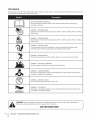 6
6
-
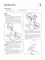 7
7
-
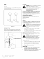 8
8
-
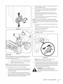 9
9
-
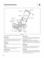 10
10
-
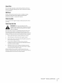 11
11
-
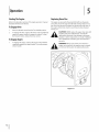 12
12
-
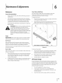 13
13
-
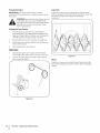 14
14
-
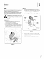 15
15
-
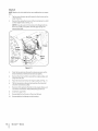 16
16
-
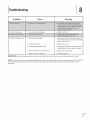 17
17
-
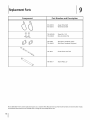 18
18
-
 19
19
-
 20
20
-
 21
21
-
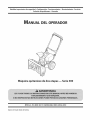 22
22
-
 23
23
-
 24
24
-
 25
25
-
 26
26
-
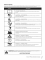 27
27
-
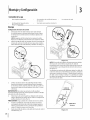 28
28
-
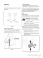 29
29
-
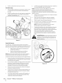 30
30
-
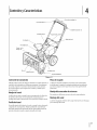 31
31
-
 32
32
-
 33
33
-
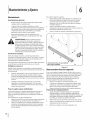 34
34
-
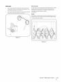 35
35
-
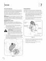 36
36
-
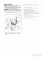 37
37
-
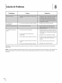 38
38
-
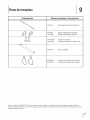 39
39
-
 40
40
-
 41
41
-
 42
42
-
 43
43
-
 44
44


MTD 31A-32AD700 El manual del propietario
- Categoría
- Lanzadores de nieve
- Tipo
- El manual del propietario
- Este manual también es adecuado para
en otros idiomas
- English: MTD 31A-32AD700 Owner's manual
Artículos relacionados
-
MTD 31A-3CAD752 El manual del propietario
-
-
-
-
-
-
-