Aeg-Electrolux DD8795-M Manual de usuario
- Tipo
- Manual de usuario

Manual de
instrucciones
User manual
Campana extractora
Cooker Hood
DD 8795

2
Indice
Recomendaciones de seguridad..................................................... 3
Descripción del aparato ................................................................... 5
Funcionamiento extractor ................................................................... 5
Funcionamiento de recirculación ........................................................ 5
Funcionamiento de la campana ...................................................... 6
Dispositivo de control del filtro ............................................................ 7
Mantenimiento y cuidado ................................................................ 8
Filtro grasa ......................................................................................... 8
Como quitar los paneles frontales: ..................................................... 8
Filtro de carbón activado .................................................................. 10
Sustitución de la bombilla ................................................................. 11
Limpieza .......................................................................................... 11
Accesorios especiales ................................................................... 12
Servicio de asistencia técnica....................................................... 12
Características técnicas................................................................. 13
Accesorios/Piezas de montaje incluidas........................................... 13
Conexión eléctrica.......................................................................... 14
Montaje............................................................................................. 15

3
Recomendaciones de seguridad
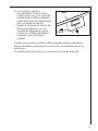
• En caso de funcionamiento de aspiración, salida libre, el tubo de
descarga debe tener el mismo diámetro del anillo de conexión.
Atención: tubo no suministrado, se puede adquirir
separadamente.
Si en la pared o en el techo ya existe un tubo de aspiración del aire
con un diámetro igual a 125 mm, se puede utilizar el manguito de
reducción 150/125 mm.
El funcionamiento del equipo será un poco más ruidoso.
• Durante la instalaciòn, respetar las siguientes distancias
minimas desde la base hornillas:
base hornillas eléctricas 300mm
• Atención! No conectar el aparato a la red eléctrica hasta que la
instalación fue completada.
• Antes de cualquier operación de limpieza o mantenimento,
desenchufar la campana o el interruptor general de la casa.
• El aparato no está destinado para el uso por parte de los niños o
personas con problemas fisicos o mentales y sin experiencia y
conocientos a menos que no sea bajo control de profesionales para
el uso del aparato, una persona responsable para vuestra
seguridad.
• Los niños deben ser controlados para evitar que jueguen con el
aparato.
• Nunca utilizar la campana sin la parrilla correctamente montada!
• La campana no va Nunca utilizada como plano de apoyo solo si es
expresamente indicado.
• El ambiente debe poseer suficiente ventilación, cuando la campana
de cocina es utilizada conjuntamente con otros aparatos a gas u
otros combustibles.
• El aire aspirado no debe ser mezclado en un conducto para
descarga de humo producidos por aparatos a gas u otros
combustibles.
• Es prohibido cocinar alimentos con llama alta por debajo de la
campana.
• El uso de las llamas libres puede provocar daños a los filtros y dar
lugar a incendios, por lo tanto evitar en cada caso.
• Las frituras deben ser cocinadas bajo control para evitar que el
aceite recalentado prenda fuego.
• En cuanto a las medidas técnicas y de seguridad adoptar para la
descarga de humo atenerse estrictamente a las reglas de las
autoridades locales.

4
• La campana se debe limpiar siempre internamente y externamente
(COMO MINIMO UNA VEZ AL MES, respetando las reglas
indicadas en este manual)
• No efectuar los consejos de limpieza de la campana y el cambio de
los filtros puede provocar incendios.
• No utilice o deje la campana sin las lámparas correctamente
montadas, debido a riesgos de cortocircuito.
• Se declina todo tipo de responsabilidades, daños o incendios
provocados por no leer atentamente las instrucciones indicadas en
este manual.
Este aparato lleva el marcado CE en conformidad con la Directiva
2002/96/EC del Parlamento Europeo y del Consejo sobre residuos de
aparatos eléctricos y electrónicos (RAEE).
La correcta eliminación de este producto evita consecuencias
negativas para el medioambiente y la salud.
El símbolo en el producto o en los documentos que se incluyen
con el producto, indica que no se puede tratar como residuo
doméstico. Es necesario entregarlo en un punto de recogida para
reciclar aparatos eléctricos y electrónicos.
Deséchelo con arreglo a las normas medioambientales para
eliminación de residuos.
Para obtener información más detallada sobre el tratamiento,
recuperación y reciclaje de este producto, póngase en contacto con el
ayuntamiento, con el servicio de eliminación de residuos urbanos o la
tienda donde adquirió el producto.

5
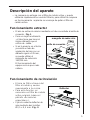
Descripción del aparato
• La campana se entrega con el filtro de carbón activo, y puede
utilizarse rápidamente en versión filtrante, para utilizar la campana
en funcionamiento aspirante se aconseja de quitar el filtro de
carbón activo.
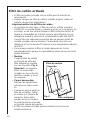
Funcionamiento extractor
• El aire se extrae al exterior mediante un tubo conectado al anillo de
conexión . Fig. 1.
• Para un mejor rendimiento
, el tubo tiene que tener el
mismo diámetro que el
orificio de salida.
• Si en la pared o en el techo
ya existe un tubo de
aspiración del aire con un
diámetro igual a 125 mm,
se puede utilizar el
manguito de reducción
150/125 mm.
El funcionamiento del
equipo será un poco más
ruidoso.
Funcionamiento de recirculación
• El aire se filtra a traves del
filtro al carbón y vuelve
nuevamente a la cocina.
• Para esta función, es
necesario un filtro de carbón
activo original (véase el
párrafo «Accesorios
especiales»).
• Fijar el conducto deflector de
aire mediante dos tornillos
Ø3,5 x 9,5 mm. Fig. 2.
anillo de conexión
manguito de reducción
Fig. 1
Deflector
Fig. 2

6
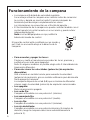
Funcionamiento de la campana
• La campana está dotada de velocidad regulable.
Se aconseja activar la campana unos minutos antes de comenzar
la cocción y dejarla en marcha hasta 15 minutos después de
terminarla para desalojar completamente los olores.
Los interruptores se encuentran en el frontal del aparato :
• El funcionamiento de la campana se puede controlar también con el
control remoto (el control remoto es un accesorio y puede actuar
independientemente).
Nota: si el led L2 parpadea en rojo,sustituir la
bateria del mando de control.
El panel de control está constituido por un mando y
por 2 led; se encuentra abajo a la derecha de la
campana.
• Para encender y apagar las luces:
Presione y suelte el mando para encender las luces, presione y
suéltelo una vez más para apagarlas.
Nota: En algunos modelos es posible elegir entre 2 intensidades de
iluminación diferentes.
• Para seleccionar las velocidades (potencias) de aspiración
disponibles:
Gire el mando en sentido horario para aumentar la velocidad
(potencia) de aspiración, gire en sentido antihorario para disminuirla
hasta apagar la campana.
La campana dispone de un led (L1) que se ilumina de diferentes
colores según la velocidad (potencia) de aspiración seleccionada:
• Luz apagada:
Motor de aspiración apagado
• Luz verde fija:
Campana encendida con una potencia 1 (mínima).
• Luz anaranjada fija:
Campana encendida con una potencia 2 (media).
• Luz roja fija:
Campana encendida con una potencia 3 (máxima).
• Luz roja destellante:
Campana encendida con una potencia intensiva (5 minutos de
duración, luego la campana selecciona automáticamente la
potencia 3).
L1
L2
Fig. 3

7
Dispositivo de control del filtro
La campana posee un dispositivo que señala cuándo se debe limpiar
o sustituir el filtro.
Normalmente el dispositivo que avisa cuando es necesario realizar el
mantenimiento del filtro de carbón, está desactivado.
Para activarlo, proceda de la siguiente manera:
Apague la campana.
Presione el mando durante más de 5 segundos.
El led L2 comienza a destellar de color verde, después de 2 segundos
aproximadamente, comenzará a destellar también de color
anaranjado para indicar que el dispositivo que avisa cuando es
necesario realizar el mantenimiento del filtro de carbón está activado.
Led L2 – indicador del filtro de grasa
El Led se ilumina de color verde cuando el filtro de grasa necesita ser
limpiado, esto sucede aproximadamente cada 40 horas.
Cada vez que se utiliza la campana, controle si el Led L2 está
encendido.
Led L2 – indicador del filtro de carbón
El Led se ilumina de color anaranjado cuando el filtro de carbón
necesita ser limpiado o sustituido, esto sucede aproximadamente
cada 160 horas.
Cada vez que se utiliza la campana, controle si el Led L2 está
encendido.
Reiniciación de la señalización de saturación de
filtros
Después de haber limpiado o sustituido los filtros, encienda la campa-
na a una velocidad (potencia) de aspiración cualquiera y presione el
mando durante más de 3 segundos hasta escuchar una señal sonora
que indica que se ha producido la reiniciación, el led L2 y la campana
se apagarán.
En algunos casos, (por ejemplo: cuando el led L2 está indicando tanto
la saturación de los filtros de grasa como la del filtro de carbón) es
necesario repetir la operación descrita arriba.

8
Mantenimiento y cuidado
• Antes de realizar cualquier operación de limpieza o
mantenimiento, desconecte la campana de la red eléctrica
desenchufándola o desconectando el interruptor general de la
vivienda.
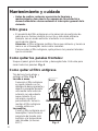
Filtro grasa
• El propósito del filtro antigrasas es la absorción de partículas de
grasa que se forman durante la cocción y éste debe utilizarse
siempre, sea en modo extractor al exterior o en modo de
recirculación interna.
Atención: el filtro antigrasa metálico tiene que extraerse y lavarse a
mano o en el lavavajillas cada cuatro semanas.
Para acceder al filtro antigrasa, quite primero los paneles laterales
que lo esconden.
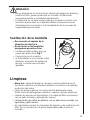
Como quitar los paneles frontales:
Saque el panel, gírelo hacia arriba y desengánchelo. Esto vale para
sacar todos los paneles. Fig. 4.
Como quitar el filtro antigrasa
Tire del asa hacia abajo y
extraiga el filtro. Fig. 5.
Lavado a mano
Sumergir el filtro antigrasa
en agua caliente con un
detergente desengrasante y
dejarlo sumergido durante
una media hora antes de
aclararlo con abundante
agua caliente. Si es
necesario, repetir el
procedimiento. Volver a
montar el filtro antigrasa
cuando esté seco.
Lavavajillas
Poner el filtro antigrasa en el
lavavajillas. Seleccionar el
programa de lavado más
enérgico y la temperatura
más elevada (al menos
65°C).
Bild 3
Fig. 4
Desenganchar
Sacar

9
Si es necesario, repetir el
procedimiento. Montar el filtro
cuando esté seco. Con el lavado
en lavavajillas, el filtro antigrasa
puede descolorearse ligeramente
pero no pierde su eficacia.
• Limpiar el alojamiento interior del
filtro exclusivamente con una
solución de detergente y agua
caliente (no utilizar detergentes
cáusticos, polvo abrasivo o
cepillos).
Cuando haya vuelto a instalar el filtro antigrasa vuelva a montar los
paneles frontales siguiendo las instrucciones en sentido inverso a la
extracción.
El panel frontal más estrecho se monta en la posición más alta.
Asa
Fig. 5

10
Filtro de carbón activado
• El filtro de carbón activado solo se utiliza para la función de
recirculación.
• Instalar siempre un filtro de carbón activado original. (véase el
párrafo «Accesorios especiales»).
Limpieza\sustitución del filtro de carbón
• Al contrario de otros tipos, el filtro de carbón, el filtro al carbón
LONGLIFE se puede limpiar y volverlo a poner en la campana. Se
aconseja, en un uso normal, limpiar el filtro cada dos meses. El
lavado en lavavajillas es la mejor manera para limpiarlo.Use un
detergente normal y seleccione la temperatura más alta (65°C).
Lave el filtro por separado para evitar que se peguen restos de
comida y puedan causar mal olor. Para poderlo usar otra vez,
métalo en el horno durante 10 minutos a una temperatura máxima
de 100°C.
• Se aconseja cambiar el filtro al carbón después de 3 años
aproximadamente porque la capacidad de absorción de los olores
podría disminuir.
• Montaje
Ponga el filtro de carbón
en la parte de atrás del
filtro antigrasa y sujételo
con dos soportes. Fig. 6.
Atención! Los soportes
filtros se encuentran
incluidos en la confección
del filtro a carbón y no en
la campana.
• Para el desmontaje,
efectuar las operaciones
anteriores en orden inver-
so.
• Cuando se vaya a pedir un
filtro de recambio, indicar
el modelo y el número de
producto. Estos datos
pueden leerse en la placa
de características colocada
en la parte interna del aparato.
• El filtro de carbón activado puede solicitarse al servicio de
asistencia técnica.
Filtro antigrasa
Filtro de carbón
Suportes
Fig. 6

11
Atención
• De no observarse las instrucciones dadas para limpiar el aparato y
sustituir el filtro, puede producirse un incendio. El fabricante
recomienda leerlas y respetarlas atentamente.
• El fabricante no se hace responsable por los daños al motor o los
incendios provocados en el aparato debido a intervenciones de
mantenimiento incorrectas o al incumplimiento de las normas de
seguridad proporcionadas.
Sustitución de la bombilla
• Desconectar el aparato de la
alimentación eléctrica.
• Antes de tocar las bombillas
asegurarse que esten frias.
• Cambie el bulbo antiguo por uno
nuevo del mismo tipo. Fig. 7
• Ponga otra vez el conector.
• Si la bombilla no se enciende, antes
de llamar al servicio de asistencia
técnica, controlar que esté bien
ajustada.
Limpieza
• Atención : antes de limpiar la campana, desconectarla de la ali-
mentación eléctrica. No introducir objetos con punta en la rejilla de
protección del motor.
• Lavar las partes externas con una solución detergente suave.
Evitar el uso de detergentes cáusticos, cepillos y polvos abrasivos.
• Limpiar el panel de los interruptores y la rejilla del filtro únicamente
con un paño húmedo y detergentes suaves.
• Limpiar todas las partes de plástico con un paño suave rociado con
agua tibia y jabón neutro.
• Es importante respetar los intervalos de limpieza y de sustitución del
filtro. De no hacerse así, la grasa depositada puede causar un
incendio.
Fig. 7

12
Accesorios especiales
Control remoto RM 6940
Chimenea telescópica K 8004 M (sólo para versión aspirante)
Paneles laterales de aluminio BD 8004 A
Paneles laterales de vidrio BD 8004-W
Filtro de carbón activado Type 31
Servicio de asistencia técnica
En caso de dudas o desperfectos, ponerse en contacto con nuestro centro de
asistencia técnica (ver lista).
En caso de avería se ruega indicar:
1. Modelo
2. E-Nr.
3. F-Nr.
Estos datos pueden leerse en la placa de características colocada en la parte
interna del aparato, quitando la rejilla del filtro para grasas.
El fabricante se reserva el derecho de realizar las modificaciones de construcción o
color que estime necesarias por razones de la evolución
tecnológica.
Si la campana no funciona
Antes de llamar al servicio técnico
Compruebe si está enchufada y que los fusibles no estén fundidos. No
haga nada que pueda causar daños físicos en el aparato. Si el
problema continúa, contacte con su vendedor o el servicio técnico
adecuado.
Servicio técnico y recambios
Cuando solicite asistencia técnica o recambios, tenga a mano el número
de producto (PNC) y la denominación del modelo. Encontrará estos
datos en la placa de características.
Retire el filtro de grasa y encontrará la placa de características.
Modelo:
Nr. de producto
Fecha de adquisición
Llame al teléfono 902 11 63 88

13
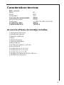
Características técnicas
Dim. - (en cm)
Altura 80
Ancho 89,8
Profundidad 33,3
Consumo de corriente total: 290 W
Absorción de motor: 230 W
Iluminación: 3 x 20W (30° Ø35 12V GU4)
Longitud de cable: 150cm
Conexión eléctrica: 110-127 V
Accesorios/Piezas de montaje incluidas
1 llave para tornillos torx
1 escarpia de sujeción
1 deflector salida aire
2 tapas
1 bandas de goma
1 máscara de taladrar
2 distanciadores
4 tornillos de madera 5 x 45 mm
4 tacos Ø 8 mm
2 tornillos de rosca 3,5 x 9,5
2 tornillos de rosca 3,5 x 32
2 tornillos de rosca 5 x 18
1 manguito de reducción Ø 150-125 mm
2 abrazaderas de apriete

14
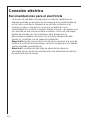
Conexión eléctrica
Recomendaciones para el electricista
La tensión de red debe corresponder con tensión indicada en la
etiqueta colocada en el interno de la campana.Si es suministrada de
un enchufe, enchufar la campana a un enchufe conforme a las
normas en vigor y colocarlo en una zona accesible.Si no es
suministrada con enchufe (conexión directa a la red) o de espina y no
es colocada en una zona accesible accesible, colocar un interruptor
bipolar de acuerdo con las normativas, para asegurarse la
desconexión completa a la red en el caso de la categoria de alta
tensión III, conforme con las reglas de instalación.
Atención! Antes de reconectar el circuito de la campana a la red y de
verificar el correcto funcionamiento, controlar siempre que el cable de
red fue montado correctamente.
Atención! La sustitución del cable de alimentación debe ser
efectuado por el servicio de asistencia técnica autorizado de manera
de evitar todo tipo de riesgo.

15
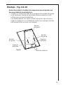
Antes de realizar la instalación asegurarse que el aparato sea
desconectado de la red eléctrica.
• Coloque en la parte de atrás de la campana tres bandas de goma.
Si es necesario, monte los dos distanciadores adjuntos en los
orificios para la sujeción definitiva.
Los distanciadores son útiles cuando la pared a la que hay que
colgar la campana no es totalmente vertical ( por ejemplo cuando
está cubierta sólo en parte de azulejos)
Montaje - Fig. 8-9-10
Fig. 8
Distanciadores
bandas
de goma
Sujecion
definitiva
bandas
de goma
bandas
de goma
Sujecion
definitiva

16
1
2
3
4
4
5
5
6
6
7
8
8
9
(5x18)
(5x18)
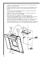
• Señale en la pared con una línea central, ésto le ayudará para la
operación de montaje (1)
• Coloque la plantilla de manera que la línea central dibujada en la
plantilla coincida con lo que se ha señalado anteriormente en la
pared.
La cara inferior de la plantilla coincide con la parte inferior de la
campana una vez montada.(2).
• Haga dos orificios de 8mm de diámetro , ponga la escarpia de
sujeción con dos tacos y atornille (3).
• Quite el frontal ( vea capítulo “ Como quitar el frontal”).
• Cuelgue la campana(4), ajuste su posición (5,6) y desde el interior
de la campana haga dos señales en dos puntos donde se
instalará definitivamente.(7) Quite la campana y haga dos orificios
de 8mm. Ponga dos tacos (8), cuelgue otra vez la campana y
móntela definitivamente con dos tornillos (9). Cubra los orificios que
ha hecho para los tornillos con dos tapas cubretornillos adjuntas.
Fig. 9

17
1
2
3
4
10
12
11
11
Versión aspirante
Versión
filtrante
Fig. 10
• Realice la conexión eléctrica (10) pero deje la campana
desconectada de la red principal.
• En caso de que use la campana en versión aspirante, sitúe una de
las dos arandelas que van incluidas en la salida del orificio (11
aspirante).
Atención! Usted debe usar la arandela larga cuando haya que
instalar una chimenea telescópica (este accesorio hay que pedirlo-
vease accesorios especiale), la arandela corta hay que usarla en
los demás casos.
• Vuelva a montar el filtro antigrasa y los paneles frontales (12) según
la numeración que se indica en cada panel ( de arriba a abajo de 1
a 4).
• Conecte la campana a la red principal y compruebe que la campa-
na funcione bien.

18
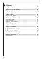
Contents
Safety warnings.............................................................................. 19
Description of the Appliance ......................................................... 21
Extraction mode................................................................................ 21
Recirculation mode ........................................................................... 21
Control Panel.................................................................................. 22
Filter checking device........................................................................ 23
Maintenance and care ................................................................... 24
Cleaning the hood ............................................................................. 24
Metal grease filter ............................................................................. 24
Removing the front panels ................................................................. 25
Charcoal filter .................................................................................... 26
Changing the light bulb...................................................................... 27
Special accessories........................................................................ 28
Technical assistance service ......................................................... 28
Technical Specifications................................................................ 30
Mounting accessories included ......................................................... 30
Electrical connection ..................................................................... 31
Wall mounting ................................................................................... 32

19
Safety warnings
• When used as an extractor unit, the hood must be fitted with a hose
having preferably the same diameter as the outlet hole.
Attention: The hose is not supplied and must be purchased
separately.
• Should there already be a pipe of diameter 125 mm that ducts to the
outside through the walls or roof, it is possible to use the 150/125
mm reduction flange provided. In this case the hood will be slightly
noisier.
• When installing the hood observe the following minimum
distances from the cooking top:
Electric cooking hobs 30cm
• Before any cleaning or maintenance operation, disconnect the hood
from the mains by removing the plug or disconnecting the home
mains switch.
• The appliance is not intended for use by children or persons with
impaired physical, sensorial or mental faculties, or if lacking in
experience or know-how, unless they are under supervision or have
been trained in the use of the appliance by a person responsible for
their safety.
• Children should be monitored to ensure that they do not play with the
appliance.
• Never use the hood without effectively mounted grating.!
• The hood must NEVER be used as a support surface unless
specifically indicated.
• The premises must be sufficiently ventilated, when the kitchen hood
is used together with other gas combustion devices or other fuels.
• The suctioned air must not be conveyed into a conduit used for the
disposal of the fumes generated by appliances that combust gases
or other fuels.
• The flaming of foods beneath the hood itself is severely prohibited.
• The use of exposed flames is detrimental to the filters and may
cause a fire risk, and must therefore be avoided in all circumstances.
• Any frying must be done with care in order to make sure that the oil
does not overheat and burst into flames.
• As regards the technical and safety measures to be adopted for
fume discharging it is important to closely follow the relations
provided by the competent authorities.
• The hood must be regularly cleaned on both the inside and outside
(AT LEAST ONCE A MONTH, it is in any event necessary to proceed
in accordance with the maintenance instructions provided in this
manual).

20
• Failure to follow the instructions as concerns hood and filter cleaning
will lead to the risk of fires.
• Do not use or leave the hood without the lamp correctly mounted
because of the possible risk of electric shocks.
• We decline any responsibility for any problems, damage or fires
caused to the appliance as the result of the non-observance of the
instructions included in this manual.
This appliance is marked according to the European directive 2002/96/EC
on Waste Electrical and Electronic Equipment (WEEE).
By ensuring this product is disposed of correctly, you will help prevent
potential negative consequences for the environment and human health,
which could otherwise be caused by inappropriate waste handling of this
product.
The symbol on the product, or on the documents accompanying the
product, indicates that this appliance may not be treated as household
waste. Instead it shall be handed over to the applicable collection point for
the recycling of electrical and electronic equipment.
Disposal must be carried out in accordance with local environmental
regulations for waste disposal.
For more detailed information about treatment, recovery and recycling of
this product, please contact your local city office, your household waste
disposal service or the shop where you purchased the product.

21
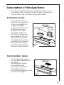
Description of the Appliance
• The hood is supplied with the charcoal filter, and can be used
immediately in the recirculation mode. We advise removing the
charcoal filter to use the hood in the extraction mode.
Extraction mode
• In this version fumes are
extracted to the outside via
a hose connected to the
coupling ring. Fig. 1.
• In order to obtain the best
performance the hose
should have a diameter
equal to the outlet hole.
• Should there already be a
pipe of diameter 125 mm
that ducts to the outside
through the walls or roof, it
is possible to use the 150/
125 mm reduction flange
provided. In this case the
hood will be slightly noisier.
Recirculation mode
• The air is filtered through a
charcoal filter and returned to
the kitchen.
• You will need an original
charcoal filter for the
recirculation mode. (See
Special Accessories).
• Fix the deflector using 2 screws
Ø 3.5x9.5 mm. Fig. 2.
coupling ring
reduction
flange
Fig. 1
Deflector
Fig. 2
•

22
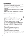
Control Panel
• Best results are obtained by using a low speed for normal conditions
and a high speed when odours are more concentrated.
Turn the hood on a few minutes before you start cooking, you will
then get an under pressure in the kitchen. The hood should be left on
after cooking for about 15 minutes or until all the odours have
disappeared.
• Cooker hood operation can also be controlled using the remote
control (the remote control is an accessory and may be ordered
separately).
Note: if the L2 LED flashes, then replace remote control battery.
The control panel consists of a knob and 2 LEDs; it is located at the
bottom right-hand side of the cooker hood.
• To switch the lights on and off:
Press and release the knob to switch the lights on;
press and release it again to switch them off.
Note: in some models it is possible to select one of
2 different lighting intensity levels.
• To select an available suction speed (power)
level:
Turn the knob in a clockwise direction to increase
the suction speed (power); turn it in an anticlockwise direction to
decrease the power until the hob is switched off.
The cooker hood is fitted with an LED (L1) which indicates the
suction speed (power) selected by displaying different colours:
• Light off:
Suction motor switched off.
• Fixed green light:
Cooker hood operating at power level 1 (minimum).
• Fixed orange light:
Cooker hood operating at power level 2 (medium).
• Fixed red light:
Cooker hood operating at power level 3 (maximum).
• Flashing red light:
Cooker hood operating at an intensive power level (for a duration of 5
minutes, after which the appliance automatically selects power level
3).
L1
L2
Fig. 3

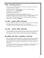
23
Filter checking device
The cooker hood is fitted with a device which indicates when the filter
must be cleaned or replaced.
Usually the device, which signals when the carbon filter needs
maintenance work, is deactivated.
To activate it, proceed as follows:
Switch off the cooker hood.
Press and hold the knob for approximately 5 seconds.
The L2 LED begins to flash in green and after approximately 2 seconds
the L2 LED will also begin to flash in orange, to indicate that the
device, which indicates when it is necessary to perform carbon filter
maintenance, has been activated.
L2 LED - grease filter indicator
The LED lights up in green when the grease filter needs to be cleaned;
this happens approximately every 40 hours of operation.
Every time the cooker hood is used, check whether the L2 LED is lit.
L2 LED - carbon filter indicator
The LED lights up in orange when the carbon filter needs to be cleaned/
replaced; this happens approximately every 160 hours of operation.
Every time the cooker hood is used, check whether the L2 LED is lit.
Resetting the filter saturation warning
After cleaning or replacing the filters, switch on the cooker hood at any
suction speed (power), then press and hold the knob for more than 3
seconds, until you hear a beep indicating that the reset procedure has
been performed successfully. The L2 LED and the cooker hood both
switch off.
In some situations (for example, when the L2 LED is indicating that the
grease filters and the carbon filter are saturated), the procedure
described above must be repeated.

24
Maintenance and care
• Before performing any maintenance operation, isolate the hood from
the electrical supply by switching off at the connector and removing
the connector fuse.
Or if the appliance has been connected through a plug and socket,
then the plug must be removed from the socket.
Cleaning the hood
• Clean the outside of the hood using a damp cloth and a solution of
water and mild washing up liquid.
• Never use corrosive, abrasive or flammable cleaning products or
products containing bleach.
• Never insert pointed objects in the motor’s protective grid.
• Only ever clean the switch panel and filter grill using a damp cloth
and mild washing up liquid.
• Clean all the plastic parts with a soft cloth soaked in warm water and
neutral soap.
• It is extremely important to clean the unit and change the filters at
the recommended intervals. Failure to do so will cause grease
deposits to build up that could constitute a fire hazard.
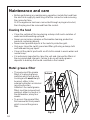
Metal grease filter
• The purpose of the grease
filters is to absorb grease
particles which form during
cooking and it must always
be used, either in the
external extraction or internal
recycling function.
Attention: the metal grease
filters must be removed and
washed, either by hand or in
the dishwasher, every four
weeks.
• To access the grease filter,
first remove the front panels
which conceal the grease
filter.
Bild 3
Fig. 4
Unhook
Extract

25
Handle
Fig. 5
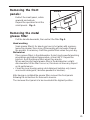
Removing the front
panels:
Extract the small panel, rotate
upwards and unhook.
Repeat the operation for all the
small panels. Fig. 4.
Removing the metal
grease filter
Pull the handle downards, then extract the filter.Fig. 5.
Hand washing
Soak grease filter(s) for about one hour in hot water with a grease-
loosening cleaner, then rinse off thoroughly with hot water. Repeat
the process if necessary. Refit the grease filters when they are dry.
Dishwasher
Place grease filters in the dishwasher. Select most powerful washing
programme and highest temperature, at least 65°C. Repeat the
process. Refit the grease filters when they are dry.
When washing the metal grease filter in the dishwasher a slight
discolouration of the filter can occur, this does not have any impact
on its performance.
• Clean the inner housing using a hot detergent solution only (never
use caustic detergents, abrasive powders or brushes).
After having re-installed the grease filter, remount the front panels
following the instructions for removal in reverse.
The narrower front panel is to be mounted at the highest position.

26
Charcoal filter
• The charcoal filter should only be used if you want to use the hood in
recirculation mode.
• To do this you will need an original charcoal filter (available from your
local Service Force Centre).
• Cleaning/replacing the charcoal filter
Unlike other carbon filters, the LONGLIFE carbon filter can be
cleaned and reactivated. With normal use the filter should be cleaned
every second month (when using the hood 2,5 hours per day, on
avarage). The best way to clean the filter is in the dishwasher. Use
normal detergent and choose the highest temperature (65º C). Wash
the filter separately so that no food parts gets stuck on the filter and
later causes bad odours. To reactivate the filter, the filter should be
dried in an oven for 10 minutes with a maximum temperature of
100ºC.
After approximately three years of use, the charcoal filter should be
replaced with a new, as the odour reduction capacity will be reduced.
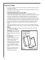
• Fitting
Fit the charcoal filter on the rear side of the grease filter, fix it with
two metal wires. Fig. 6.
Attention! The metal wires
are included in the carbon
filter packing and not on the
hood
• To remove proceed in the
reverse order.
• Always specify the hood
model code number and
serial number when
ordering replacement filters.
This information is shown
on the registration plate
located on the inside of the
unit.
• The charcoal filter can be
ordered from your local
Service Force Centre.
grease filter
charcoal filter
metal wires
Fig. 6

27
Warning
• Failure to observe the instructions on cleaning the unit and changing
the filters will cause a fire hazard. You are therefore strongly
recommended to follow these instructions.
• The manufacturer declines all responsibility for any damage to the
motor or any fire damage linked to inappropriate maintenance or
failure to observe the above safety recommendations.
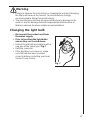
Changing the light bulb
• Disconnect the cooker hood from
the mains supply.
• Prior to touching the light bulbs
ensure they are cooled down.
• Extract the old bulb and replace with a
new one of the same type. Fig. 7
• Refit the connector.
• If the light does not come on, make
sure the bulb has been inserted
correctly before contacting your local
Service Force Centre.
Fig. 7

28
Special accessories
Remote control RM 6940*
Telescopic chimney
(for extraction mode only)* 942 120 750
Aluminium side panels 942 120 769
Glass side panels 942 120 965
Charcoal filter Type 31
* Not available in UK.
Technical assistance service (not for UK)
You are welcome to telephone our technical assistance service (see list of technical
assistance centres) whenever you need information or in the unlikely event of a fault.
For service in Australia call 1300 650 020.
When calling, please be ready to specify:
1. The model code number
2. The serial number (E-Nr.)
3. The manufacturing number (F-Nr.)
This information is shown on the registration plate inside the unit behind the
grease filter.
We reserve the right to change specifications and colours as a result of our policy of
continuing technological development.
Service and Spare Parts
In the event of your appliance requiring service, or if you wish to purchase spare parts,
contact your local Service Force Centre by telephoning: 08705 929 929
Your call will be automatically routed to the Service Centre covering your post code
area. For the address of your local Service Force Centre and further information about
Service Force, please visit the website at www.serviceforce.co.uk
Please ensure that you have read the section “What to do if...” as the engineer will make
a charge if the fault is not a mechanical or electrical breakdown even the appliance is
under warranty. Please note that proof of purchase is required for in-guarantee
service calls.
Help us to help you
Please determine your type of enquiry before writing or telephoning.
When you contact us we need to know:
• Your name • Clear and concise details of the fault
• Address and post code • Name and model of the appliance*
• Telephone number • E number*
• Serial number*
* This information can be found on the rating plate, which can be seen when the grease
filters are removed.

29
If you require Customer Service in the Republic of Ireland please contact us at
the address below:
AEG
Electrolux Group (Ire) Ltd
Long Mile Road
Dublin 12
Republic of Ireland
Tel: + 353 (0) 1 4090751
Email: [email protected]
CUSTOMER CARE DEPARTMENT
For general enquiries concerning your AEG appliance or for further information on AEG
products, please contact our Customer Care Department by letter or telephone at the
address below or visit our website at www.aeg.co.uk
Customer Services Department
Major Appliances
AEGElectrolux
Addington Way
Luton
Bedfordshire
LU4 9QQ
08705 350 350 (*)
* calls to this number may be recorded for training purposes

30
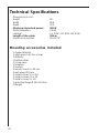
Technical Specifications
Dimensions (in cm):
Height 80
Width 89,8
Depth 33,3
Maximum absorbed power: 290 W
Motor absorption: 230 W
Lighting*: 3 x 20W (30° Ø35 12V GU4)
Length of the cable: 150cm
Electrical connection: 110-127 V
Mounting accessories included
1 support bracket
1 allan wrench for torx screws
1 deflector
1 Rubber strips
2 Screw caps
1 template
2 spacers
4 wood-screws 5 x 45 mm
4 wall plugs Ø 8 mm
2 metal screws 3,5 x 9,5
2 metal screws 3,5 x 32
2 metal screws 5 x 18
1 reduction flange Ø 150-125 mm
2 flanges

31
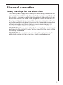
Electrical connection
Safety warnings for the electrician
The mains power supply must correspond to the rating indicated on the
plate situated inside the hood. If provided with a plug connect the hood
to a socket in compliance with current regulations and positioned in an
accessible area. If it not fitted with a plug (direct mains connection) or if
the plug is not located in an accessible area apply a bi-polar switch in
accordance with standards which assures the complete disconnection
of the mains under conditions relating to over-current category III, in
accordance with installation instructions.
IMPORTANT: Before re-connecting the hood circuit to the mains supply
and checking the efficient function, always check that the mains cable
is correctly assembled.
IMPORTANT! Power cable replacement must be undertaken by the
authorized service assistance centre or similar qualified person.

32
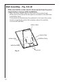
Make sure that the cooker hood is disconnected from the power
supply before carrying out the installation.
• Place the three rubber strips on the back of the cooker hood.
Where necessary mount the two spacers provided on the drill holes
for definitive fixing.
The spacers are useful when the wall which is to house the cooker
hood is not perfectly vertical (for example: where it is partially
covered with wall tiles).
Wall mounting - Fig. 8-9-10
Fig. 8
rubber strips
spacers
definitive fixing
rubber strips
rubber strips
definitive fixing

33
1
2
3
4
4
5
5
6
6
7
8
8
9
(5x18)
(5x18)
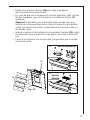
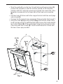
• Mark the wall with a centre line, this will aid mounting procedure (1),
position the template so that the mid line printed on the template
matches with the centre line previously marked, the lower side of the
template corresponds to the lower side of the hood once mounted
(2).
• Drill two holes Ø 8mm and fix the support bracket with two wall plugs
and screws (3).
• Remove the front panels (see paragraph “Removing the front panels”).
• Hang the hood (4) adjust its position (5-6) and from the inside of the
hood sign two points for definitive fixing (7), remove the hood and drill
two holes Ø 8mm (8), fit two wall plugs, hang the hood again and fix
it securely with two screws (9). Cover the drill holes for screws with
the two screw caps provided.
Fig. 9

34
1
2
3
4
10
12
11
11
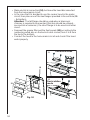
Extraction mode
Recirculation
mode
Fig. 10
• Make electrical connection (10), but leave the hood disconnected
from the home mains circuit.
• In the case that it is decided to use the cooker hood in the mains
circuit, then place one of the two flanges provided in the exit hole (11
– Extraction).
Attention! The tall flange should be used when a telescopic
chimney is required to be mounted (this item should be ordered –
see special accessories), the short flange is to be used in all other
cases.
• Remount the grease filter and the front panels (12) according to the
numbering noted also on the back of each screen (from 1 to 4 from
the top to the bottom).
• Connect the hood to the home mains circuit and check if the hood
works properly.

35

LI3FWA Ed. 02/08
-
 1
1
-
 2
2
-
 3
3
-
 4
4
-
 5
5
-
 6
6
-
 7
7
-
 8
8
-
 9
9
-
 10
10
-
 11
11
-
 12
12
-
 13
13
-
 14
14
-
 15
15
-
 16
16
-
 17
17
-
 18
18
-
 19
19
-
 20
20
-
 21
21
-
 22
22
-
 23
23
-
 24
24
-
 25
25
-
 26
26
-
 27
27
-
 28
28
-
 29
29
-
 30
30
-
 31
31
-
 32
32
-
 33
33
-
 34
34
-
 35
35
-
 36
36


Aeg-Electrolux DD8795-M Manual de usuario
- Tipo
- Manual de usuario
en otros idiomas
- English: Aeg-Electrolux DD8795-M User manual
Otros documentos
-
Electrolux EFCR90441U Manual de usuario
-
-
Infiniton CMP-HB90P3 El manual del propietario
-
Electrolux EFA9673X Manual de usuario
-
-
-
-
-
-