MTD 247985370 El manual del propietario
- Categoría
- Lanzadores de nieve
- Tipo
- El manual del propietario
Este manual también es adecuado para

Operator's Manual
CRRFr MRN
26" SNOW THROWER
Model No. 247.985370
CAUTION" Before using this
product, read this manual and
follow all safety rules and operating
instructions.
,, SAFETY
o ASSEMBLY
OPERATION
MAINTENANCE
PARTS LIST
o ESPANOL
Sears Brands Management Corporation, Hoffman Estates, IL 60179, U.S.A.
Visit our website: www.craftsman.com FormNo. 769-08192C
(August3,2012)

WarrantyStatement.................... Page2
SafeOperationPractices.............. Pages3-6
Assembly......................... Pages8-13
Operation........................ Pages14-17
Service&Maintenance.............. Pages18-23
Off-SeasonStorage................... Page24
Troubleshooting...................... Page25
PartsList......................... Pages26-43
RepairProtectionAgreement............ Page47
Espadol............................. Page48
ServiceNumbers................... BackPage
CRAFTSMANTWOYEARFULLWARRANTY
FORTWOYEARSfromthedateofpurchase,thisproductiswarrantedagainstanydefectsinmaterialorworkmanship.Defectiveproductwill
receivefreerepairorfreereplacementifrepairisunavailable.
Forwarrantycoverage details to obtain repairor replacement,visit the website: www.craftsman.com
This warranty covers ONLYdefects in materialandworkmanship. Warrantycoverage does NOTinclude:
• Expendableitemsthatcanwearoutfromnormalusewithinthewarrantyperiod,includingbutnotlimitedtoaugers,augerpaddles,drift
cutters,skidshoes,shaveplate,shearpins,sparkplug,air cleaner,belts,andoil filter.
• Standardmaintenanceservicing,oilchanges,or tune-ups.
• Tirereplacementor repaircausedbypuncturesfromoutsideobjects,suchasnails,thorns,stumps,or glass.
• Tireor wheelreplacementor repairresultingfromnormalwear,accident,orimproperoperationor maintenance.
• Repairsnecessarybecauseof operatorabuse,includingbutnotlimitedtodamagecausedbyover-speedingtheengine,or fromimpacting
objectsthat bendtheframe,augershaft,etc.
• Repairsnecessarybecauseof operatornegligence,includingbutnotlimitedto,electricalandmechanicaldamagecausedbyimproper
storage,failureto usethepropergradeandamountofengineoil,orfailureto maintaintheequipmentaccordingtotheinstructionscontained
intheoperator'smanual.
• Engine(fuelsystem)cleaningor repairscausedbyfueldeterminedto becontaminatedoroxidized(stale).Ingeneral,fuelshouldbeused
within30 daysof itspurchasedate.
Normaldeteriorationandwearoftheexteriorfinishes,or productlabelreplacement.
Thiswarrantyisvoidifthisproductiseverusedwhileprovidingcommercialservicesor if rentedtoanotherperson.
Thiswarrantygivesyouspecificlegalrights,andyoumayalsohaveotherrightswhichvaryfromstatetostate.
Sears Brands Management Corporation, Hoffman Estates, IL 60179
EngineOilType: SAE5W-30
EngineOilCapacity: 20ounces
FuelCapacity: 2Quarts
SparkPlug: F6RTC(951-10292)
SparkPlugGap: .020"to .030"
ModelNumber.................................................................
Serial Number.................................................................
Dateof Purchase .............................................................
Recordthemodelnumber,serialnumber
anddateof purchaseabove
©SearsBrands,LLC
2

Thissymbolpointsoutimportantsafetyinstructionswhich,if not
followed,couldendangerthepersonalsafetyand/orpropertyof
yourselfandothers.Readandfollowallinstructionsin thismanual
beforeattemptingtooperatethismachine.Failuretocomplywith
theseinstructionsmayresultin personalinjury.Whenyouseethis
symbol,HEEDITSWARNING!
CALIFORNIA PROPOSITION 65
EngineExhaust,someof itsconstituents,andcertainvehicle
componentscontainoremitchemicalsknowntoStateofCalifornia
tocausecancerandbirthdefectsorotherreproductiveharm,
Thismachinewasbuilttobeoperatedaccordingtothesafeopera-
tionpracticesinthis manual.Aswithanytypeof powerequipment,
carelessnessorerroron thepartoftheoperatorcanresultin serious
injury.Thismachineiscapableofamputatingfingers,hands,toes
andfeetandthrowingdebris.Failuretoobservethefollowingsafety
instructionscouldresultin seriousinjuryor death.
Your Responsibility--Restrict theuseofthispowermachineto
personswhoread,understandandfollowthewarningsand instruc-
tionsin thismanualandon themachine,
SAVE THESE INSTRUCTIONS!
TRAiNiNG
• Read,understand,andfollowall instructionson themachineand
in themanual(s)beforeattemptingtoassembleandoperate.
Failuretodo socan resultinseriousinjurytotheoperatorand/
orbystanders.Keepthismanualin a safeplaceforfutureand
regularreferenceandfororderingreplacementparts.
• Befamiliarwithall controlsandtheirproperoperation.Knowhow
tostopthemachineanddisengagethemquickly.
• Neverallowchildrenunder14yearsofagetooperatethis
machine.Children14andovershouldreadandunderstandthe
instructionsandsafeoperationpracticesin thismanualandon
themachineandbe trainedandsupervisedbyanadult.
Neverallowadultstooperatethis machinewithoutproper
instruction.
• Thrownobjectscancauseseriouspersonalinjury.Planyour
snow-throwingpatterntoavoiddischargeof materialtoward
roads,bystandersandthelike.
Keepbystanders,petsandchildrenat least75feetfromthe
machinewhileitisin operation.Stopmachineifanyoneenters
thearea.
• Exercisecautiontoavoidslippingor falling,especiallywhen
operatingin reverse.
PREPARATION
Thoroughlyinspecttheareawheretheequipmentistobeused.
Removeall doormats,newspapers,sleds,boards,wiresandother
foreignobjects,whichcouldbe trippedoverorthrownbytheauger/
impeller.
• Alwayswearsafetyglassesor eyeshieldsduringoperationand
whileperformingan adjustmentor repairto protectyoureyes.
Thrownobjectswhichricochetcancauseseriousinjurytothe
eyes.
Donotoperatewithoutwearingadequatewinteroutergarments.
Donotwearjewelry,longscarvesorotherlooseclothing,which
couldbecomeentangledin movingparts.Wearfootwearwhich
willimprovefootingonslipperysurfaces.
Usea groundedthree-wireextensioncordand receptacleforall
machineswithelectricstartengines.
Disengageall controlleversbeforestartingtheengine.
Adjustcollectorhousingheighttocleargravelorcrushedrock
surfaces.
• Neverattempttomakeanyadjustmentswhileengineis running,
exceptwherespecificallyrecommendedintheoperator'smanual.
Letengineandmachineadjusttooutdoortemperaturebefore
startingtoclearsnow.
3

SafeHandlingof Gasoline
Toavoidpersonalinjuryor propertydamageuseextremecarein
handlinggasoline.Gasolineisextremelyflammableandthevaporsare
explosive.Seriouspersonalinjurycanoccurwhengasolineisspilled
onyourselfor yourclotheswhichcanignite. Washyourskinand
changeclothesimmediately.
• Useonlyan approvedgasolinecontainer.
• Extinguishallcigarettes,cigars,pipesandothersourcesof
ignition.
• Neverfuelmachineindoors.
• Neverremovegascapor addfuelwhiletheengineishotor
running.
• Allowenginetocoolat leasttwo minutesbeforerefueling.
• Neveroverfillfueltank.Filltankto nomorethan1/2inchbelow
bottomoffillernecktoprovidespaceforfuelexpansion.
• Replacegasolinecapandtightensecurely.
• Ifgasolineisspilled,wipeitoff theengineandequipment.Move
machinetoanotherarea.Wait5 minutesbeforestartingthe
engine.
• Neverstorethemachineorfuelcontainerinsidewherethereisan
openflame,sparkor pilotlight(e.g.furnace,waterheater,space
heater,clothesdryeretc.).
• Allowmachinetocoolatleast5 minutesbeforestoring.
• Neverfillcontainersinsidea vehicleor ona truckor trailerbed
witha plasticliner.Alwaysplacecontainersonthegroundaway
fromyourvehiclebeforefilling.
• If possible,removegas-poweredequipmentfromthetruckor
trailerandrefuelitontheground.Ifthis isnotpossible,thenrefuel
suchequipmenton a trailerwitha portablecontainer,ratherthan
froma gasolinedispensernozzle.
• Keepthenozzlein contactwiththerimofthefueltankor
containeropeningatalltimesuntilfuelingiscomplete.Donotuse
a nozzlelock-opendevice.
OPERATION
• Donotputhandsorfeetnear rotatingparts,in theauger/impeller
housingor chuteassembly.Contactwiththerotatingpartscan
amputatehandsandfeet.
• Theauger/impellercontrolleverisa safetydevice.Neverbypass
itsoperation.Doingsomakesthemachineunsafeandmaycause
personalinjury.
• Thecontrolleversmustoperateeasilyin bothdirectionsand
automaticallyreturntothedisengagedpositionwhenreleased.
• Neveroperatewitha missingor damagedchuteassembly.Keep
all safetydevicesin placeandworking.
• Neverrunanengineindoorsor ina poorlyventilatedarea.Engine
exhaustcontainscarbonmonoxide,anodorlessanddeadlygas.
• Donotoperatemachinewhileundertheinfluenceofalcoholor
drugs.
• Mufflerandenginebecomehotandcancausea burn.Donot
touch.Keepchildrenaway.
• Exerciseextremecautionwhenoperatingon orcrossinggravel
surfaces.Stayalertforhiddenhazardsor traffic.
Exercisecautionwhenchangingdirectionandwhileoperatingon
slopes.Donotoperateon steepslopes.
Planyoursnow-throwingpatternto avoiddischargetowards
windows,walls,carsetc.Thus,avoidingpossibleproperty
damageor personalinjurycausedbya ricochet.
Neverdirectdischargeatchildren,bystandersand petsor allow
anyoneinfrontofthemachine.
Donotoverloadmachinecapacitybyattemptingtoclearsnowat
toofastof a rate.
Neveroperatethis machinewithoutgoodvisibilityorlight.Always
be sureofyourfootingand keepa firmholdon thehandles.Walk,
neverrun.
Disengagepowertotheauger/impellerwhentransportingor not
in use.
Neveroperatemachineathightransportspeedson slippery
surfaces.Lookdownand behindand usecarewhenbackingup.
Ifthemachineshouldstarttovibrateabnormally,stoptheengine,
disconnectthesparkplugwireandgrounditagainsttheengine.
Inspectthoroughlyfordamage.Repairanydamagebefore
startingandoperating.
Disengageall controlleversandstopenginebeforeyouleave
theoperatingposition(behindthehandles).Waituntiltheauger/
impellercomestoa completestopbeforeuncloggingthechute
assembly,makinganyadjustments,or inspections.
Neverputyourhandinthedischargeor collectoropenings.Do
notunclogchuteassemblywhileengineisrunning.Shutoff
engineand remainbehindhandlesuntilall movingpartshave
stoppedbeforeunclogging.
Useonlyattachmentsandaccessoriesapprovedbythemanufac-
turer(e.g.wheelweights,tirechains,cabsetc.). Forinformation
concerningtheseitems,call1-800-469-4663.
Whenstartingengine,pullcordslowlyuntilresistanceisfelt,then
pull rapidly.Rapidretractionofstartercord(kickback)willpull
handandarmtowardenginefasterthanyoucanletgo.Broken
bones,fractures,bruisesor sprainscouldresult.
Ifsituationsoccurwhichare notcoveredinthis manual,usecare
andgoodjudgment.
Toorderpartsor scheduleserviceforthisproduct,call 1-800-
469-4663.
CLEARING A CLOGGED DISCHARGE CHUTE
Handcontactwiththe rotatingimpellerinsidethedischargechute
is themostcommoncauseofinjuryassociatedwithsnowthrowers.
Neveruseyourhandtocleanoutthedischargechute.
Toclearthechute:
1. SHUTTHEENGINEOFF!
2. Wait10secondstobe suretheimpellerbladeshavestopped
rotating.
3. Alwaysuseaclean-outtool,notyourhands.
4

MAINTENANCE & STORAGE
• Nevertamperwithsafetydevices.Checktheirproperoperation
regularly.Refertothemaintenanceandadjustmentsectionsof
thismanual.
• Beforecleaning,repairing,or inspectingmachinedisengageall
controlleversandstoptheengine.Waituntiltheauger/impeller
cometoa completestop.Disconnectthe sparkplugwireand
groundagainsttheenginetopreventunintendedstarting.
Checkboltsand screwsforpropertightnessatfrequentintervals
tokeepthemachineinsafeworkingcondition.Also,visually
inspectmachineforanydamage.
Donotchangetheenginegovernorsettingor over-speedthe
engine.Thegovernorcontrolsthe maximumsafeoperatingspeed
oftheengine.
Snowthrowershaveplatesand skidshoesaresubjecttowear
anddamage.Foryoursafetyprotection,frequentlycheckall
componentsand replacewithoriginalequipmentmanufacturer's
(OEM)partsonlyaslistedinthe Partspagesof thisoperator's
manual.Useofpartswhichdonotmeettheoriginalequipment
specificationsmayleadto improperperformanceandcompro-
misesafety!
Checkcontrolleversperiodicallytoverifytheyengageanddisen-
gageproperlyandadjust,ifnecessary.Refertotheadjustment
sectioninthisoperator'smanualforinstructions.
Maintainor replacesafetyandinstructionlabels,asnecessary.
Observeproperdisposallawsand regulationsforgas,oil,etc.to
protecttheenvironment.
Priorto storing,runmachinea few minutestoclearsnowfrom
machineand preventfreezeupofauger/impeller.
Neverstorethemachineorfuelcontainerinsidewherethereisan
openflame,sparkorpilotlightsuchasa waterheater,furnace,
clothesdryeretc.
Alwaysrefertotheoperator'smanualforproperinstructionson
off-seasonstorage.
Checkfuelline,tank,cap,andfittingsfrequentlyforcracksor
leaks.Replaceifnecessary.
Donotcrankenginewithsparkplugremoved.
AccordingtotheConsumerProductsSafetyCommission(CPSC)
andtheU.S.EnvironmentalProtectionAgency(EPA),thisproduct
hasan AverageUsefulLifeof seven(7)years,or 60 hoursof
operation.AttheendoftheAverageUsefulLifehavethemachine
inspectedannuallybyan authorizedservicedealertoensurethat
allmechanicalandsafetysystemsareworkingproperlyand not
wornexcessively.Failuretodo socanresultinaccidents,injuries
ordeath.
DO NOT MODIFY ENGINE
Toavoidseriousinjuryor death,do notmodifyengineinanyway.
Tamperingwiththegovernorsettingcanleadtoa runawayengineand
causeittooperateat unsafespeeds.Nevertamperwithfactorysetting
ofenginegovernor.
NOTICE REGARDING EMiSSiONS
EngineswhicharecertifiedtocomplywithCaliforniaandfederal
EPAemissionregulationsforSORE(SmallOff RoadEquipment)are
certifiedtooperateon regularunleadedgasoline,and mayinclude
thefollowingemissioncontrolsystems:EngineModification(EM),
OxidizingCatalyst(OC),SecondaryAirInjection(SAI)and ThreeWay
Catalyst(TWO)if soequipped.
SPARK ARRESTOR
Thismachineisequippedwithaninternalcombustionengineand
shouldnotbe usedonor nearanyunimprovedforest-covered,
brush-coveredorgrass-coveredlandunlesstheengine'sexhaust
systemisequippedwitha sparkarrestormeetingapplicablelocalor
statelaws(ifany)
Ifa sparkarrestorisused,itshouldbe maintainedin effectiveworking
orderbytheoperator.IntheStateofCaliforniatheaboveis required
bylaw(Section4442oftheCaliforniaPublicResourcesCode).Other
statesmayhavesimilarlaws.Federallawsapplyonfederallands.
A sparkarrestorforthemufflerisavailablethroughyournearestSears
PartsandRepairServiceCenter.

SAFETY SYMBOLS
Thispagedepictsanddescribessafetysymbolsthatmayappearonthisproduct. Read,understand,andfollowall instructionson themachine
beforeattemptingtoassembleandoperate.
. +
i
i
"JIp
READ THE OPERATOR'S MANUAL(S)
Read, understand, and follow all instructions in the manual(s) before attempting to assemble and
operate
WARNING-- ROTATING BLADES
Keep hands out of inlet and discharge openings while machine is running. There are rotating blades
inside
WARNING-- ROTATING BLADES
Keep hands out of inlet and discharge openings while machine is running. There are rotating blades
inside
WARNING-- ROTATING AUGER
Do not put hands or feet near rotating parts, in the auger/impeller housing or chute assembly.
Contact with the rotating parts can amputate hands and feet.
WARNING--THROWN OBJECTS
This machine may pick up and throw objects which can cause serious personal injury.
WARNING--GASOLINE ISFLAMMABLE
Allow the engine to cool at least two minutes before refueling.
WARNING-- CARBON MONOXIDE
Never run an engine indoors or in a poorly ventilated area. Engine exhaust contains carbon
monoxide, an odorless and deadly gas+
WARNING-- ELECTRICAL SHOCK
Do not use the engine's electric starter in the rain
6

Thispageleftintentionallyblank.
7

NOTE:Referencesto rightorleft sideofthesnowthrowerare
determinedfrombehindtheunitintheoperatingposition(standing
directlybehindthesnowthrower,facingthe handlepanel).
REMOVING FROM CARTON
1. Cutthecornersofthecartonandlaythesidesflaton theground.
Removeanddiscardallpackinginserts.
2. Movethesnowthroweroutofthecarton.
3. Makecertainthecartonhasbeencompletelyemptiedbefore
discardingit.
ASSEMBLY
1. Observethe lowerrearareaofthesnowthrowertobesureboth
cablesarealignedwith rollerguidesbeforepivotingthehandle
upward.
a. PlacetheshiftleverintheF6position.
b. Pullupandbackon upperhandleasshownin Figure1.As
youare raisingthehandleupward,makesurethat bothends
ofthecentercablearepositionedproperlyinthebrackets.
Alignupperhandlewiththelowerhandle.
c. Tightenhandknobssecuringupperhandletolowerhandle.
Removeanddiscardanyrubberbands,ifpresent.Theyare
forpackagingpurposesonly.
2. Removecotterpin,wingnut,and hexscrewfromchutecontrol
headandclevispinandbow-tiecotterpinfromchutesupport
bracket.See Figure2.
3. Insertthechutecontrolrodintoinputofchutecontrolhead.Push
rodasfarintothechutecontrolheadaspossible,keepingthe
holesinthe rodpointingupward.See Figure3.
Chute Control Head
_ort
Bracket
Figure2
f
/
\
Figure3
_J
Figure1
8

4. Placechuteontochutebaseandensurechutecontrolrodis
positionedunderhandlepanel.Installhexboltpreviouslyremoved
butdonotsecurewithwingnutatthistime.SeeFigure4.
5. Squeezethetriggeron thehandlepaneljoystickand rotatethe
chutebyhandtofaceforward.Theholesinthechutecontrolinput
willbefacingup.SeeFigure5.
NOTE:Thechutewillnotrotatewithoutsqueezingthetriggeronthe
joystick.
6. Rotatethejoysticktotheoneo'clockpositionsothesilverindica-
torarrowon theinputshaftbelowthecontrolpanelpoints
upward.SeeFigure6.
NOTE:Thejoystickwillbe angledslightlyto theright.SeeFigures5 &
6.
Figure4
f
Chute Controlf
Figure5
f
FroatView
Joystick
Figure6
J
9

. Makesureallcablesareroutedtotheleftofthechutecontrol
rod.Lineuptheholein therodwiththearrowon theinputshaft
and inserttheendoftherodintotheinputshaftbelowjoystickon
handlepanel.SeeFigure7.
NOTE:Thechutecontrolrodwillfit snugglyintotheinputshaft.
Supporttherearofthedashpanelwithone handwhileinsertingthe
rodwithyourotherhandto ensuretherodisinsertedell the way into
theinputshaft.
8. Nowpushthechutecontrolrodbacktowardsthehandlepanel
untiltheholeinthe rodlinesupwiththeholeinthechutecontrol
inputclosesttothechutecontrolhead.Insertthecotterpin.See
Figure8.
NOTE:Thesecondholeis usedtoachievefurtherengagementofthe
rodintotheinputshaftifrequiredandcanbe usedlaterforadjustment
ifthechutedoesnotfullyrotate.RefertotheService& Maintenance
sectionforChuteControlRodadjustments.
9. Finishsecuringchutecontrolheadto chutesupportbracketwith
wingnut,andclevispinandbow-tiecotterpin removedearlier.Do
notovertighten.SeeFigure9.
/i _
.J
Figure8
/
/
' .....................................................i_"i
}
Figure7
Figure9
10

10. Checkthatall cablesare properlyroutedthroughthecableguide
ontheengine.SeeFigure10.
NOTE:Ifthechutecontrolisnotassembledcorrectlyitwillnotmove
freelynorwillit movefullytotherightandleft.
SET-UP
Shear Pins
Holesare locatedinthehandlepanelforconvenientshearpin storage.
SeeFigure11.RefertotheOperationsectionformoreinformation
regardingshearpin replacement.
/
i
/
!
I
Figure10
f
Figure11
J
11

Chute Clean=Out Tool
Achute clean-out tool isfastenedtothetopoftheaugerhousing
witha mountingclip.SeeFigure12.Thetoolisdesignedtocleara
chuteassemblyoficeandsnow.Thisitemisfastenedwitha cabletie
atthefactory.Cutthecabletiebeforeoperatingthesnowthrower.
loft _1 .allmovingloartshave
stoppedbeforeusingtheclean-outtooltoclearthechuteassembly.
Tire Pressure
Underanycircumstancedo notexceedmanufacturer'srecom-
mendedpsi. Equaltirepressureshouldbe maintainedatall times.
Excessivepressurewhenseatingbeadsmaycausetire/rim
assemblytoburstwithforcesufficienttocauseseriousinjury.Refer
tosidewallof tirefor recommendedpressure.
Thetiresareover-inflatedforshippingpurposes.Checkthetire
pressurebeforeoperatingthesnowthrower.Refertothetiresidewall
fortiremanufacturer'srecommendedpsianddeflate(or inflate)the
tiresasnecessary.
NOTE:Equaltirepressureistobe maintainedat alltimesforperfor-
mancepurposes.
ADJUSTMENTS
Skid Shoes
Thesnowthrowerskidshoesareadjustedupwardatthefactoryfor
shippingpurposes.Adjustthemdownward,ifdesired,priortooperat-
ingthesnowthrower.
It isnotrecommendedthatyouoperatethis snowthrowerongravel
asitcaneasilypickup andthrowloosegravel,causingpersonal
njuryordamageto thesnowthrowerand surroundng property.
• Forclosesnowremovalona smoothsurface,raiseskidshoes
higherontheaugerhousing.
• Usea middleor lowerpositionwhentheareatobe clearedis
uneven,suchasa graveldriveway
NOTE:If youchoosetooperatethesnowthrowerona gravelsurface,
keeptheskidshoesin positionformaximumclearancebetweenthe
groundandtheshaveplate.
i
Chutedean=out Tool
Figure12
Smooth Surface
Surface
Figure13
Toadjusttheskidshoes:
1. Loosenthefourhexnuts(twooneachside)andcarriagebolts.
Moveskidshoestodesiredposition.SeeFigure13.
2. Makecertaintheentirebottomsurfaceof skidshoeisagainstthe
groundtoavoidunevenwearontheskidshoes.
3. Retightennutsand boltssecurely.
12

Chute f "_
Thedistancesnowisthrowncanbeadjustedbychangingtheangleof
theupperchute.Todo so:
1. Stoptheenginebyremovingtheignitionkeyandloosenthe
plasticwingknobfoundontheleft sideofthechuteassembly.
2. Pivotthechuteupwardordownwardbeforeretighteningthewing
knob.See Figure14.
Auger Control
Priortooperatingyoursnowthrower,carefullyreadandfollowall
instructionsbelow.Performall adjustmentsto verifyyoursnow
throwerisoperatingsafelyandproperly.
Checktheadjustmentoftheaugercontrolasfollows:
1. Theaugercontrolislocatedontheleft handle.SeeFigure15
inset.Whentheaugercontrolis releasedandin thedisengaged
"up"position,thecableshouldhaveverylittleslack.Itshould
NOTbetight.
2. Inawell-ventibtedarea,startthesnowthrowerengine.Referto
StartingtheEngineintheOperationsection.
3. Whilestandingintheoperator'sposition(behindthe snow
thrower),engagetheaugers.
4. Allowtheaugersto remainengagedforapproximatelyten(10)
secondsbeforereleasingtheaugercontrol.Repeatthisseveral
times.
5. Withtheaugercontrolin thedisengaged"up"position,walktothe
frontofthemachine.
6. Confirmthattheaugershavecompletelystoppedrotatingand
showNOsignsof motion.If anyaugershowsANYsignof
rotating,immediatelyreturntotheoperator'spositionandshutoff
theengine.WaitforALLmovingpartstostopbeforeadjustingthe
augercontrol.
7. Toreadjustthecontrolcable,loosentheupperhexboltonthe
augercablebracket.SeeFigure15.
8. Positionthebracketupwardtoprovidemoreslack(or downward
toincreasecabletension).
9. Retightentheupperhexbolt.
10. Repeatsteps2-6aboveto verifyproperadjustmenthasbeen
achieved.
Figure14
\ \
\\
\
Figure15
J
13

f
Drive Control
Shift Lever
J Two=Way Chute Control (Joystick)
/
er Control
Gas Cap
\
AugerHousim
ChuteAssembly
\\\
\,
\
Clean Out
Tool
\
\
\
Augers
Skid Shoe
-Wheel Steering Control
Nluffler Recoil Starter
\ Handle
Primer \_ _ FUELLEVEL
Key
:lectric Start
Button
/ /
Oil Drain Electric Starter Outlet
Figure16
Nowthat youhavesetup yoursnowthrower,it'simportanttobecome
acquaintedwith itscontrolsandfeatures.RefertoFigure16.
Throttle
Control
Choke
Control
,J
NOTE:Donotturnthekeyinan attempttostarttheengine.Doingso
maycauseittobreak.
SHIFT LEVER
Theshiftleverislocatedonthe rightsideofthehandlepanel.
Placetheshiftleverintoanyofeightpositionstocontrolthe
directionoftravelandgroundspeed.
Forward
6 CHOKE CONTROL
5 Thechokecontrolisfoundon therearoftheengineand isactivated
4 byturningtherotarychokeknobtotheCHOKEposition.Activating
thechokecontrolclosesthechokeplateon thecarburetorandaidsin
3 startingtheengine,
Yoursnowthrowerhassixforward(F)speeds.Positionone(1)is t 2
theslowestand positionsix (6) isthefastest. F 1
Reverse
Yoursnowthrowerhastwo reverse(R)speeds.One(1)isthe
slowerandtwo(2) isthefaster.
KEY
Thekeyisa safetydevice.It mustbefully insertedinorderforthe
enginetostart.Removethekeywhenthesnowthrowerisnotinuse.
PRIMER
Depressingthe primerforcesfueldirectlyintotheengine'scarburetor
toaid incold-weatherstarting.
OIL FILL
Engineoil levelcanbecheckedandoiladdedthroughtheoil fill.
GAS CAP
Unthreadthegascaptoadd gasolinetothefueltank.
Meets ANSi Safety Standards
CraftsmanSnowThrowersconformtothesafetystandardoftheAmericanNationalStandardsInstitute(ANSI).
14

THROTTLE CONTROL
Thethrottlecontrolis locatedon therearoftheengine.It regulatesthe
speedoftheengineandwillshutoff theenginewhenmovedintothe
STOPposition.
RECOIL STARTER HANDLE
Thishandleisusedto manuallystarttheengine.
ELECTRIC STARTER BUTTON
Pressingtheelectricstarterbuttonengagestheengine'selectric
starterwhenpluggedintoa 120Vpowersource.
ELECTRIC STARTER OUTLET
Requirestheuseof athree-prongoutdoorextensioncordanda 120V
powersource/walloutlet.
AUGERS
Whenengaged,theaugerbladesrotateand drawsnowintotheauger
housing.
SKID SHOES
Positiontheskid shoesbasedon surfaceconditions.Adjustupward
forhard-packedsnow.Adjustdownwardwhenoperatingon gravelor
crushedrocksurfaces.
CHUTE ASSEMBLY
Snowdrawnintotheaugerhousingisdischargedoutthechute
assembly.
WHEEL STEERING CONTROLS
Theleft andrightwheelsteeringcontrolsarelocatedon theunderside
ofthehandles.Squeezetherightcontroltoturnright;squeezetheleft
controltoturnleft.
NOTE:Operatethesnowthrowerinopenareasuntilyouarefamiliar
withthesecontrols.
Theaugercontrolislocatedon thelefthandle.Squeezethecontrol
gripagainstthehandletoengagetheaugerandstartsnowthrowing
action.Releasetostop.
DRIVE CONTROL/AUGER CONTROL LOCK
DRIVE
CONTROL
Thedrivecontrolis locatedon therighthandle.Squeezethecontrol
gripagainstthehandletoengagethewheeldrive.Releasetostop.
Thedrivecontrolalsolockstheaugercontrolsoyoucanoperate
thechutedirectionalcontrolwithoutinterruptingthesnowthrowing
process.If theaugercontrolisengagedsimultaneouslywiththedrive
control,theoperatorcanreleasetheaugercontrol(onthelefthandle)
andtheaugerswillremainengaged.Releasebothcontrolstostopthe
augersandwheeldrive.
NOTE:Alwaysreleasethedrivecontrolbeforechangingspeeds.
Failureto dosowillresultinincreasedwearon yourmachine'sdrive
system.
TWO-WAY CHUTE CONTROL
r
CHUTE DiRECTiONAL CONTROL
CHUTEROTATE CHUTEROTATE
LEFT RIGHT
AUGER CONTROL
_ J
Thetwo-waychutecontrol(Joystick)is locatedon theleftsideofthe
handlepanel.
* Tochangethedirectioninwhichsnowisthrown,squeezethe
buttononthechutecontrolleverand pivotthechutecontrollever
tothe rightortotheleft.
15

CLEAN-OUT TOOL
Neveruseyourhandstocleara cloggedchuteassembly.Shut
loft engineand remainbehindhandlesuntilallmovingpartshave
lstoppedbeforeusingtheclean-outtooltoclearthechuteassembly.
Thechuteclean-outtoolisconvenientlyfastenedtotherearofthe
augerhousingwitha mountingclip. Shouldsnowandicebecome
lodgedin thechuteassemblyduringoperation,proceedasfollowsto
safelycleanthechuteassemblyandchuteopening:
1. ReleaseboththeAugerControlandtheDriveControl.
2. Stoptheenginebyremovingtheignitionkey.
3. Removetheclean-outtoolfromtheclipwhichsecuresittothe
rearoftheaugerhousing.
4. Usetheshovel-shapedendof theclean-outtooltodislodgeand
scoopanysnowand icewhichhasformedin andnearthechute
assembly.
5. Refastentheclean-outtooltothemountingclipontherearof
theaugerhousing,reinserttheignitionkeyandstartthesnow
thrower'sengine.
6. Whilestandingintheoperator'sposition(behindthesnow
thrower),engagetheaugercontrolfora fewsecondstoclearany
remainingsnowandicefromthechuteassembly.
BEFORE STARTING ENGINE
Read,understand,andfollowall instructionsandwarningson the
machineand inthismanualbeforeoperating.
Oil
Theunit wasshippedwith oil inthe engine.Checkoil levelbefore
eachoperationtoensureadequateoil intheengine.Forfurther
instructions,refertothe stepson page18.
NOTE:Besuretochecktheengineon a levelsurfacewiththeengine
stopped.
1. Removetheoil fillercap/dipstickandwipethedipstickclean.
2. insertthecap/dipstickintotheoilfillerneck,butdo NOTscrewit
in.
3. Removetheoil fillercap/dipstick,ifthelevelislow,slowlyadd
oil (5%30, witha minimumclassificationof SF/SG)untiloil level
registersbetweenhigh(H) andlow(L).
NOTE:Donotoverfill.Overfillingwithoil mayresultinenginesmoking,
hardstartingor sparkplugfouling.
4. Replaceandtightencap/dipstickfirmlybeforestartingengine.
Gasoline
Useautomotivegasoline(unleadedor lowleadedtominimizecombus-
tionchamberdeposits)witha minimumof87octane.Gasolinewith
upto 10%ethanolor 15%MTBE(MethylTertiaryButylEther)canbe
used.Neveruseanoil/gasolinemixtureor dirtygasoline.Avoidgetting
dirt,dust,or waterinthefueltank.DONOTuseE85gasoline.
• Refuelina well-ventilatedareawiththeenginestopped.Donot
smokeorallowflamesor sparksin theareawheretheengineis
refueledor wheregasolineisstored.
• Donotoverfillthefueltank.After refueling,makesurethetank
capisclosedproperlyandsecurely.
• Becarefulnotto spillfuelwhenrefueling.Spilledfuelorfuelvapor
mayignite,ifanyfuelisspilled,makesuretheareaisdrybefore
startingtheengine.
• Avoidrepeatedorprolongedcontactwithskinor breathingof
)or.
Useextremecarewhenhandlinggasoline.Gasolineisextremely
flammableandthevaporsare explosive.Neverfuelthemachine
indoorsorwhiletheengineishotor running.Extinguishcigarettes,
cigars,pipesandothersourcesof ignition.
1. Cleanaroundfuelfillbeforeremovingcaptofuel.
2. Afuellevelindicatorislocatedin thefueltank.SeeFigure15
inset.Becarefulnottooverfill.Filltank untilfuelreachesthefuel
levelindicatortoallowspaceforfuelexpansion.
STARTING THE ENGINE
Alwayskeephandsandfeetclearof movingparts.Donotusea
pressurizedstartingfluid.Vaporsare flammable.
NOTE:Allowtheenginetowarmupfora fewminutesafter starting.
Theenginewillnotdevelopfullpoweruntilit reachesoperating
temperatures.
1. Makecertainboththeaugercontrolanddrivecontrolarein the
disengaged(released)position.
2. insertkeyintoslot.Makesureitsnapsintoplace.Donotattempt
toturnthekey.
NOTE:Theenginecannotstartwithoutthekeyfullyinsertedintothe
ignitionswitch.
Electric Starter
Theoptionalelectricstarterisequippedwitha groundedthree-wire
powercordandplug,and isdesignedto operateon 120voltAC
householdcurrent.It mustbeusedwitha properlygroundedthree-
prongreceptacleatall timestoavoidthepossibilityofelectricshock.
Followall instructionscarefullypriortooperatingtheelectricstarter.
DONOTuseelectricstarterintherain.
Determinethatyourhome'swiringisa three-wiregroundedsystem.
Aska licensedelectricianifyouarenotcertain.
Ifyouhavea groundedthree-prongreceptacle,proceedasfollows.
Ifyoudonothavetheproperhousewiring,DONOTusetheelectric
starterunderanyconditions.
1. Plugtheextensioncordintotheoutletlocatedon theengine's
surface.Plugtheotherendof extensioncordintoa three-prong
120-volt,grounded,ACoutletina well-ventilatedarea.
16

2. Movethrottlecontrolto FAST(rabbit)_J_" position.
3. MovechoketotheCHOKEI,'_1 position(coldenginestart).If
engineiswarm,placechokein RUNposition.
4. Pushprimerthree(3)times,makingsuretocoverventholein
primerbulbwhenpushing.If engineiswarm,pushprimeronly
once.Alwayscoverventholewhenpushing.Coolweathermay
requireprimingtobe repeated.
5. Pushstarterbuttontostartengine.Oncetheenginestarts,im-
mediatelyreleasestarterbutton.Electricstarterisequippedwith
thermaloverloadprotection;systemwilltemporarilyshut-downto
allowstartertocoolifelectricstarterbecomesoverloaded.
6. Astheenginewarms,slowlyrotatethechokecontroltoRUN
position.If theenginefalters,restartengineandrunwithchoke
athalf-chokepositionfora shortperiodoftime,andthenslowly
rotatethechokeintoRUNposition.
7. Afterengineisrunning,disconnectpowercordfromelectric
starter.Whendisconnecting,alwaysunplugtheendatthewall
outletbeforeunpluggingtheoppositeendfromtheengine.
Recoil Starter
TO ENGAGE DRIVE
1. Withthethrottlecontrolinthe Fast(rabbit)position,moveshift
leverintooneofthesixforward(F)positionsor tworeverse(R)
positions.Selecta speedappropriateforthesnowconditionsand
a paceyou'recomfortablewith.
NOTE:Whenselectinga DriveSpeed,usetheslowerspeedsuntil
youarecomfortableandfamiliarwiththeoperationofthesnow
thrower.
2. Squeezethedrivecontrolagainstthehandleandthesnow
throwerwillmove.Releaseitanddrivemotionwillstop.
NOTE:NEVERrepositiontheshiftlever(changespeedsordirection
oftravel)withoutfirstreleasingthedrivecontrolandbringingthesnow
throwertoa completestop.Doingsowill resultin prematurewearto
thesnowthrower'sdrivesystem.
TO ENGAGE AUGERS
1. Toengagetheaugersandstartthrowingsnow,squeezethe
augercontrolagainstthelefthandle.Releasetostoptheaugers.
Donotpullthestarterhandlewhiletheenginerunning.
1. Movethrottlecontrolto FAST(rabbit)_J_ position.
2. MovechoketotheCHOKEI_¢1 position(coldenginestart).If
engineiswarm,placechokein RUNposition.
3. Pushprimerthree(3)times,makingsuretocoverventholewhen
pushing.Ifengineiswarm,pushprimeronlyonce.Alwayscover
ventholewhenpushing.Coolweathermayrequireprimingtobe
repeated.
4. Pullgentlyonthe starterhandleuntilitbeginstoresist,then
pullquicklyandforcefullytoovercomethecompression.Engine
shouldstart.Donotreleasethehandleandallowittosnapback.
ReturnropeSLOWLYtooriginalposition.If required,repeatthis
step.
5. Astheenginewarms,slowlyrotatethechokecontroltoRUN
position.If theenginefalters,restartengineandrunwithchoke
athalf-chokepositionfora shortperiodoftime,andthenslowly
rotatethechokeintoRUNposition.
Toavoidunsupervisedengineoperation,neverleavethemachine
unattendedwiththeenginerunning.Turntheengineoffafteruseand
removekey.
STOPPING THE ENGINE
Afteryouhavefinishedsnow-throwing,runenginefora few minutes
beforestoppingtohelpdryoffanymoistureontheengine.
1. MovethrottlecontroltoOFFposition.
2. Removethekey.Removingthekeywillreducethepossibilityof
unauthorizedstartingoftheenginewhileequipmentisnotin use.
Keepthekeyina safeplace.Theenginecannotstartwithoutthe
key.
3. Wipeanymoistureawayfromthecontrolson theengine.
17
REPLACING SHEAR PiNS
Theaugersare securedtothespiralshaftwith shearpinsandcotter
pins.If theaugersshouldstrikeaforeignobjectoricejam,thesnow
throwerisdesignedsothatthepinsmayshear.If theaugerswillnot
turn,checktoseeifthepinshavesheared.SeeFigure17.
NEVERreplacetheaugershearpinswithanythingotherthanSears
SKU#88389/0EM PartNo.738-04124Areplacementshearpins.
Anydamagetotheaugergearboxorothercomponentsasa resultof
failingtodo sowill NOTbecoveredbyyoursnowthrower'swarranty.
Alwaysturnoff thesnowthrower'sengineand removethekeypriorto
replacingshear pins.
'i
//
Figure17

MAINTENANCE SCHEDULE
Beforeperforminganytypeofmaintenance/service,disengageall
controlsandstoptheengine.Waituntilallmovingpartshavecometo
acompletestop.Disconnectsparkplugwireandgrounditagainstthe
enginetopreventunintendedstarting.Alwayswearsafetyglassesduring
operationorwhileperforminganyadjustmentsorrepairs.
EachUseandevery5
hours
1st5 hours
Annuallyor 25 hours
Annuallyor 50 hours
Annuallyor 100hours
BeforeStorage
1. Engineoil level
2. Looseormissinghardware
3. Unitandengine.
1. Engineoil
1. Sparkplug
2. Controllinkagesandpivots
3. Wheels
4. GearshaftandAugershaft
1. Engineoil
1. Sparkplug
1. Fuelsystem
Followthemaintenanceschedulegivenbelow.Thischartdescribes
serviceguidelinesonly.UsetheServiceLogcolumntokeeptrackof
completedmaintenancetasks.Tolocate the nearest SearsService
Centeror to scheduleservice,simplycontactSearsat
1-800-4-MY-HOME®.
1. Check
2. Tightenor replace
3. Clean
1. Change
1. Check
2. Lubewithlightoil
3. Lubewithmultipurposeautogrease
4. Lubewithlightoil
1. Change
1. Change
1. Runengineuntilit stopsfromlack
d fuel
ENGINE MAINTENANCE
Checking Engine Oil
Beforelubricating,repairing,or inspecting,disengageall controls
Iandstopengine.Waituntilall movingpartshavecometo a complete
_stop.
NOTE: Checktheoil levelbeforeeachuseto besurecorrectoil level
ismaintained.
Whenaddingoiltotheengine,referto viscositychart below.Engine
oilcapacityis 600 ml(approx.20 oz.).Donotover-fill.Usea 4-stroke,
oran equivalenthighdetergent,premiumqualitymotoroilcertified
tomeetorexceedU.S.automobilemanufacturer'srequirementsfor
serviceclassificationSG,SRMotoroilsclassifiedSG,SFwillshow
thisdesignationonthecontainer.
1. Removetheoil fillercap/dipstickandwipethedipstickclean.
2. Insertthecap/dipstickintotheoilfillerneck,andtightenthecap
untilseated.
3. Removetheoil fillercap/dipstick.Iflevelislow,slowlyadd oiluntil
oil levelregistersbetweenhigh(H)andlow(L).SeeFigure18.
4. Replaceandtightencap/dipstickfirmlybeforestartingengine.
Changing Engine Oil
NOTE:Changetheengineoilafterthefirst5 hoursof operationand
oncea seasonorevery50 hoursthereafter.
1. Drainfuelfromtankbyrunningengineuntilthefueltankisempty.
Besurefuelfillcapissecure.
J
Figure18
2. Placesuitableoil collectioncontainerunderoil drainplug.
3. Removeoil drainplug.SeeFigure19on nextpage.
4. Tipunittodrainoilintothecontainer.Usedoil mustbedisposed
ofata propercollectioncenter.
Usedoil isa hazardouswasteproduct.Disposeofusedoil properly.
IDonotdiscardwithhouseholdwaste.Checkwithyourlocalauthori-
lties or SearsServiceCenterforsafedisposal/recyclingfacilities.
18

.
6.
Reinstallthedrainplugandtightenit securely.
Refillwiththerecommendedoil andchecktheoil level.See
RecommendedOil Usagechart.Theengine'soil capacityis20
ounces.
i u
[
(%-40 °-20 o 0o 200 400
("c) -300 -200 -10° 0°
DONOTusenondetergentoilor 2-strokeengineoil.Itcouldshorten
theengine'sservicelife.
Oil Drain
Plug
7. Reinstalltheoilfillercap/dipsticksecurely.
Figure19
Thoroughlywashyourhandswithsoapandwaterassoonas
possibleafterhandling usedoil.
Checking Spark Plug
DONOTcheckforsparkwithsparkplugremoved.DONOTcrank
enginewithsparkplug removed.
Iftheenginehasbeenrunning,themufflerwillbevery hot.Becareful
nottotouchthemuffler.
NOTE: Checkthesparkplugoncea seasonorevery25hoursof
operation.Changethesparkplugoncea seasonor every100hours.
Toensureproperengineoperation,thesparkplugmustbe properly
gappedandfreeofdeposits.
1. Removethesparkplugbootandusea sparkplugwrenchto
removetheplug.See Figure20.
2. Visuallyinspectthesparkplug.Discardthesparkplugifthereis
apparentwear,orifthe insulatoriscrackedor chipped.Cleanthe
sparkplugwitha wirebrushifitisto be reused.
3. Measurethepluggapwitha feelergauge.Correctas necessary
bybendingsideelectrode.SeeFigure21.Thegapshouldbeset
to.02-.03inches(0.60-0.80ram).
4. Checkthatthe sparkplugwasherisingoodconditionandthread
thesparkplugin byhandtopreventcross-threading.
5. Afterthesparkplugisseated,tightenwitha sparkplugwrenchto
compressthewasher.
NOTE:Wheninstallinga newsparkplug,tighten1/2-turnafterthe
sparkplugseatstocompressthewasher.Whenreinstallinga used
sparkplug,tighten1/8-to 1/4-turnafterthesparkplugseatsto
compressthewasher.
19
Spark Plug
O
J
Figure20
Electrode
.02-.03 in.
{0.60-0.80 ram)
Figure21

hotandcan ine.
LUBRICATION
Gear Shaft
Thegear(hex)shaftshouldbe lubricatedatleastoncea seasonor
afterevery25 hoursofoperation.
1. Topreventspillage,removeall fuelfromtank byrunningengine
untilitstops.
2. Carefullypivotthesnowthrowerupandforwardsothat itrestson
theaugerhousing.
3. Removethe lowerframecoverfromtheundersideofthesnow
throwerbyremovingtheself-tappingscrewswhichsecureit.
4. Applyalightcoatingofengineoil (or31in-1oil) tothehexshaft.
SeeFigure22.
NOTE:Whenlubricatingthehexshaft,be carefulnottogetanyoilon
thealuminumdriveplateor rubberfrictionwheel.Doingsowillhinder
thesnowthrower'sdrivesystem.Wipeoff anyexcessor spilledoil.
Wheels
Atleastoncea season,removebothwheels.Cleanandcoattheaxles
witha multipurposeautomotivegreasebeforereinstallingwheels.
Auger Shaft
Atleastoncea season,removetheshearpinson augershaft.Spray
lubricantinsideshaft,andaroundthespacersandflangebearings
foundateitherendoftheshaft.SeeFigure23.
SHAVE PLATE AND SKID SHOES
Theshaveplateand skidshoesonthebottomofthesnowthrowerare
subjecttowear.Theyshouldbecheckedperiodicallyandreplaced
whennecessary.
NOTE:Theskidshoeson thismachinehavetwowearedges.When
onesidewearsout,theycanbe rotated1800to usetheotheredge.
Toremoveskidshoes:
1. Removethetwocarriagebolts,washers(ifequipped),andhex
flangenutsthat secureeachskidshoetothesnowthrower.
2. Reassemblenewskidshoeswiththefourcarriagebolts(twoon
eachside),washers,andhexflangenuts.RefertoFigure24.
Toremoveshaveplate:
1. Removethecarriageboltsand hexnutswhichattachit tothe
snowthrowerhousing.
2. Reassemblenewshaveplate,makingsureheadsofcarriage
boltsaretotheinsideof housing.Tightensecurely.SeeFigure24.
O i
)
J' "?X
/ .... )
{;:7,_"
7/'................
Figure22
/
/
/
f
Figure23
..............'L i
7j y_........ o i J,_J
7i ......... ;7....... _,
NOTE:Augersnotshown for clarity.
Figure24
J
2O

ADJUSTMENTS
Shift Cable
If thefull rangeofspeeds(forwardandreverse)cannotbe achieved,
refertothefiguretotherightandadjusttheshiftcableasfollows:
1. Placetheshiftleverin thefastest forwardspeedposition(F6).
2. Loosenthehex nuton theshiftcableindexbracket.SeeFigure
25.
3. Pivotthebracketdownwardtotakeupslackinthecable.
4. Retightenthehexnut.
Drive Control
Whenthedrivecontrolisreleasedandin thedisengaged"up"position,
thecableshouldhaveverylittle slack.It shouldNOTbetight.Also,
ifthereisexcessiveslackin thedrivecableor iftheunitexperiences
intermittentdrivewhileusing,thecablemayneedtobeadjusted.
Checktheadjustmentofthedrivecontrolasfollows:
1. Withthedrivecontrolreleased,pushthesnowthrowergently
forward.Theunitshouldrollfreely.
2. Engagethedrivecontrolandgentlyattempttopushthesnow
throwerforward.Thewheelsshouldnotturn.Theunitshouldnot
rollfreely.
3. Withthedrivecontrolreleased,movetheshiftleverbackand
forthbetweenthe R2positionandtheF6positionseveraltimes.
Thereshouldbeno resistancein theshiftlever.
4. Ifanyoftheabovetestsfailed,thedrivecableisin needofadjust-
ment.Proceedasfollows:
a. Shutofftheengineas instructedintheOperationsection.
b. Loosenthelowerhexboltonthedrivecablebracket.See
Figure26.
c. Positionthebracketupwardtoprovidemoreslack(or
downwardto increasecabletension).
d. Retightenthelowerhexboltand repeatsteps1 through4.
f
.........
J
Chute Control Rod
Toachievemorechutecontrolrodengagementintheinputshaftunder
thehandlepanelshownin Figure7 intheAssemblysection,thechute
controlrodwillhavetobeadjusted.Referto Figure27.
Toadjustthis rod,proceedasfollows:
1. Removethecotterpin fromtheholeclosesttothechutecontrol
headon thechutecontrolinput.
2. Pulloutthechutecontrolroduntilthe holein itlinesupwiththe
otherholeinthechutecontrolinput.
3. Reinsertthecotterpinthroughthis holeandthechutecontrolrod.
Figure26
J
/
/ ,
\
\
J
Figure27
21

Auger Control
RefertotheAssemblysectionforinstructionsonadjustingtheauger
controlcable.
Skid Shoes
RefertotheAssemblysectionforinstructionsonadjustingtheskid
shoes.
BELT REPLACEMENT
Auger Belt
Toremoveandreplaceyoursnowthrower'saugerbelt,proceedas
follows:
1. Topreventspillage,removeall fuelfromtank byrunningengine
untilitstops.
2. Removethe plasticbeltcoveronthefrontoftheenginebyremov-
ingthetwoself-tappingscrews.SeeFigure28.
3. Rolltheaugerbeltoff theenginepulley.See Figure29.
4. Carefullypivotthesnowthrowerupandforwardsothat itrestson
theaugerhousing.
5. Removetheframecoverfromtheundersideofthesnowthrower
byremovingtheself-tappingscrewswhichsecureit.SeeFigure
30.
6. Removethe beltasfollows.RefertoFigure31.
A. Loosenand removetheshoulderscrewwhichactsasa belt
keeper.
B. Unhooktheaugerbrakebracketspringfromtheframe.
f
Figure28
J
Figure29
J
Figure30
f
.....i
_jz:.................
22
Figure31
J

7. Removethebeltfromaroundtheaugerpulley,andslipthebelt
betweenthesupportbracketandtheaugerpulley.SeeFigure32.
8. Reassembleaugerbeltbyfollowingtheseinstructionsinopposite
orderandmannerofremoval.
9. PerformtheAugerControltestoutlinedintheAssemblysection
ofthismanual.
NOTE:DoNOTforgettoreinstalltheshoulderscrewandreconnect
thespringtotheframeafterinstallingareplacementaugerbelt.
Drive Belt
Toremoveand replaceyoursnowthrower'sdrivebelt,proceedas
follows:
1. Topreventspillage,removeallfuelfromtankby runningengine
untilitstops.
2. Removetheplasticbeltcoveronthefrontoftheenginebyremov-
ingthetwoself-tappingscrews.See Figure28on previouspage.
3. Removethebeltfromenginepulleyasfollows.Referto Figure33.
A. Rolltheaugerbeltoff theenginepulley.
B. Useawrenchto pivottheidlerpulleytowardthe right.
C. Liftthedrivebeltoffenginepulley.
4. Carefullypivotthesnowthrowerupand forwardsothat itrestson
theaugerhousing.
5. Removetheframecoverfromtheundersideofthe snowthrower
byremovingtheself-tappingscrewswhichsecureit.Referto
Figure30.
6. Backoutthestopbolttoincreasetheclearancebetweenthe
frictionwheeldiscandfrictionwheel.SeeFigure34.
7. Slipthedrivebeltoffthefrictionwheeldiscandbetweenfriction
wheelandfrictionwheeldisc.SeeFigure34.
8. Reassembledrivebeltbyfollowingtheseinstructionsinopposite
orderand mannerofremoval.Besureto reinstallthestopbolt.
FRICTION WHEEL INSPECTION
Ifthesnowthrowerfailsto drivewith thedrivecontrolengaged,and
performingtheDriveControlCableAdjustmentfailstocorrectthe
problem,thefrictionwheelmayneedtobe replaced.Examinethe
frictionwheelrubberforsignsofwearor crackingand replacewheelif
necessary.
NOTE:Severalcomponentsmustbe removedandspecialtoolsare
requiredinordertoreplacethis snowthrower'sfrictionwheel.Ifyour
frictionwheelneedsto bereplaced,contactthenearestSearsParts&
RepairCenter.
iO i
Figure32
///
f
Frictio_
Friction
Wheel Disc
Stop
Figure33
.J
Figure34
23

Ifthe snowthrowerwillnotbe usedfor30 daysor longer,or ifit istheendofthesnowseasonwhenthelastpossibilityof snowisgone,the
equipmentneedstobestoredproperly.Followstorageinstructionsbelowtoensuretopperformancefromthesnowthrowerformanymoreyears.
PREPARING ENGINE
Enginesstoredover30daysneedtobedrainedoffueltoprevent
deteriorationandgumfromforminginfuelsystemor onessential
carburetorparts.If thegasolineinyourenginedeterioratesduring
storage,youmayneedto havethecarburetor,andotherfuelsystem
components,servicedor replaced.
1. Removeall fuelfromtank byrunningengineuntilitstops.Donot
attempttopourfuelfromtheengine.
2. Changetheengineoil.
3. Removesparkplugandpourapproximately1oz.(30 rnl)ofclean
engineoil intothecylinder.Pullthe recoilstarterseveraltimesto
distributetheoil,and reinstallthesparkplug.
4. Cleandebrisfromaroundengine,andunder,around,andbehind
muffler.Applya lightfilmofoilon anyareasthatare susceptible
torust.
• Storeina clean,dry andwellventilatedareaawayfromanyap-
pliancethatoperateswithaflameor pilotlight,suchasa furnace,
waterheater,or clothesdryer.Avoidanyareawitha spark
producingelectricmotor,or wherepowertoolsareoperated.
Neverstoresnowthrowerwithfuelintank indoorsor inpoorlyventi-
latedareas,wherefuelfumesmayreachan openflame,sparkor pilol
lightasona furnace,waterheater,clothesdryerorgasappliance.
• If possible,avoidstorageareaswithhighhumidity.
• Keeptheenginelevelin storage.Tiltingcancausefueloroil
leakage.
PREPARING SNOW THROWER
Whenstoringthesnowthrowerin anunventilatedormetalstor-
age shed,careshouldbetakentorustprooftheequipment.Using
a lightoilor silicone,coattheequipment,especiallyanychains,
springs,bearingsandcables.
• Removealldirt fromexteriorofengineandequipment.
• Followlubricationrecommendations.
• Storeequipmentin a clean,dryarea.
• Inflatethetirestothe maximumPSi.Referto tiresidewall.
24

Enginefailstostart
Enginerunningerratically/
inconsistentRPM(huntingor
surging)
Excessivevibration
Lossofpower
Unitfailstopropelitself
Unitfailstodischargesnow
1. ChokecontrolnotinCHOKEposition.
2. Sparkplugwiredisconnected.
3. Faultysparkplug.
4. Fueltankemptyor stalefuel.
5. Enginenotprimed.
6. Keynotinserted.
7. Extensioncordnotconnected(when
usingelectricstartbutton,on modelsso
equipped).
1. EnginerunningonCHOKE.
2. Stalefuel.
3. Waterordirt infuelsystem.
4. Over-governedengine.
1. Loosepartsordamagedauger.
1. Sparkplugwireloose.
2. Gascapventholeplugged.
1. Drivecableinneedofadjustment.
2. Drivebeltlooseordamaged.
3. Wornfrictionwheel.
1. Chuteassemblyclogged.
2. Foreignobjectlodgedin auger.
3. Augercableinneedof adjustment.
4. Augerbeltlooseordamaged.
5. Shearpin(s)sheared.
1. Chuteassembledincorrectly.
1. Movechokecontrolto CHOKEposition.
2. Connectwireto sparkplug.
3. Clean,adjustgap,or replace.
4. Filltankwith clean,freshgasoline.
5. PrimeengineasinstructedintheOperationSection.
6. Insertkeyfullyintotheswitch.
7. Connectoneendoftheextensioncordtotheelectric
starteroutletandtheotherendtoa three-prong
120-volt,grounded,ACoutlet.
1. Movechokecontrolto RUNposition.
2. Filltankwith clean,freshgasoline.
3. Drainfueltankby runningengineuntilitstops.Refill
withfreshfuel.
4. ContactyourSearsParts& RepairCenter.
1. Stopengineimmediatelyand disconnectsparkplug
wire.Tightenall boltsand nuts.Ifvibrationcontinues,
haveunitservicedbya SearsParts& RepairCenter.
1. Connectandtightensparkplugwire.
2. Removeiceand snowfromgascap. Becertainvent
holeisclear.
1. Adjustdrivecontrolcable.RefertoServiceand
Maintenancesection.
2. Replacedrivebelt.Referto Serviceand Mainte-
nancesection.
3. Havefrictionwheelreplacedata SearsParts&
RepairCenter.
1. Stopengineimmediatelyand disconnectsparkplug
wire.Cleanchuteassemblyandinsideofauger
housingwithclean-outtoolor a stick.
2. Stopengineimmediatelyand disconnectsparkplug
wire.Removeobjectfromaugerwith clean-outtool
ora stick.
3. Adjustaugercontrolcable.RefertoAssembly
section.
4. Replaceaugerbelt.RefertoServiceand Mainte-
nancesection.
5. Replacewith newshearpin(s).
Chutefailstoeasilyrotate180 1. Disassemblechutecontroland reassembleas
degrees directedintheAssemblysection.
NEED HORE HELP?
Yot,Fttfind. th_ answer a!ld mo_e on ma_age_y_ifeocom _ for free]
Find this and att your other product manua[s ontine.
Get answers from our team of home experts.
Get a personalized maintenance p[an for your home.
Find information and tools to he[p with home projects.
managemylife
b_e'_g_t_/_eyeu by Sea_s
25

Craftsman Snow Thrower IViodel 247.985370
!
i
26

Craftsman Snow Thrower IViodel 247.985370
D = 0 0
731-2635 SnowRemovalToolMount
2. 684-04057A-0637 ImpellerAssembly,12"Dia.
3. L710-0347 LHexScrew,3/8-16,1.75,Gr5
4. 710-0451 Bolt,Carriage,5/16-18,.750Grl
5. 710-04484 Screw,5/16-18,0.750
6. 710-0703 Screw,Carriage,1/4-20,.750,Gr5
7. 712-04063 Nut,FlangeLock,5/16-18,Nylon
8. 712-04064 Nut,FlangeLock,1/4-20,Nylon
9. 712-04065 Nut,FlangeLock,3/8-16,Nylon
10. 714-04040 CotterPin,Bow-tie
11. J725-0157 l Cable,Tie, 3/16x .05x 7.4
12. 926-04012 Nut,Push-on,.25Dia
13. 731-07525 Chute,Adapter5" Dia
14. 732-04460 Spring,Extension,.38ODx4.59
15. 736-0174 Washer,Wave,.625x .885x .015
16. 736-0242 Washer,Bell,.340x .872x .060
17. 946-04230A ClutchCable,Auger,47.23"
18. 931-2643 SnowRemovalTool
19. .738-0143 _ Screw,Shoulder,.498x .34,3/8-16
20. 938-0281 Screw,Shoulder,.625x .17,3/8-16
21. 738-04124A ShearPin,.25x 1.50
22. 941-0245 Bearing,HexFlangex .75ID
23. 941-0309 Bearing,Ball,.75IDx 1.85OD
24. 756-04224 FlatPulley,Idler, 2.75OD
25. 790-00075 Housing,Bearing,1.85ID
26. 790-00080B Bracket,AugerIdlerw/Brake
27. J918-04172B J GearboxAssembly,Auger,26"
28. 684-04264-4044 HousingAssembly,Auger26"
684-04107-0637
30. 684-04108-0637
31. 731-04870
32. 736-0188
33. 741-0493A
34. 790-00087A-0637
35. 790-00121-4044
36. 731-06439
37. 918-0123A
38. 918-0124A
39. 921-0338
40. 741-0662
41. 710-0642
42. 711-04284
D = O O
SpiralAssembly,LH
SpiralAssembly,RH
Spacer,1.25ODx .75IDx 1.00
Washer,Flat,.76x 1.49x .06
Bushing,Flange,.80ID x.91OD
Housing,1"HexBearing
ShavePlate,2.25x25.66
SlideShoe
Housing,Auger,RH Reduced
Housing,Auger,LHReduced
Seal,Oil,.750x 1.00x .125
Bearing,Flange,.75x 1.0x.59
Screw,Self-tapping,1/4-20,0.750
Axle,Auger,26"
43. 914-0161 Key,Hi-pro3/16x 5/8
44. 715-04021 Pin,Dowel,.25ODx 1.2
45. 917-04126 Shaft,Worm.75OD
46. 917-04861 Gear,Worm20T
47. 718-04071 Collar,Thrust
48. 721-0325 Plug,1/4x .437
49. 721-0327 Seal,Oil,.75x 1x .131
50. 936-0351 Washer,Flat,.760IDx 1.50D
51. 736-3084 Washer,Flat,.51x 1.12
52. 741-0663 Bearing,Flange,.75x 1.0x.925
53. 741-0661A Bearing,Flange,.75x 1.00x .975
54. 936-0159 Washer,Fiat,.349x .879x .063
55. 710-0276 Screw,Carriage,5/16-18x 1.00
27

Craftsman Snow Thrower Model 247.985370
@
28

Craftsman Snow Thrower IViodel 247.985370
684-04112C HandleEngagementAssemblyRH
2. 738-04367 FlangeShoulderScrew
3. 731-04894D LockPlate
4. 684-04250 PivotRod
5. 935-0199A RubberBumper
6. 710-3069 Screw,1/4-20x .500
7. 731-04896B ClutchLockCam
8. 712-04081A ShoulderNut,1/4-20
9. 710-0627 HexScrew,5/16-24x .750
10. 731-06440A LowerChute
11. J720-0274 J HandleGrip
12. 710-1233 Screw,#10-24x0.375
13. 738-04348 ShoulderScrew,1/4-20
14. 710-04586 Screw,1/4-20x 1.625
15. 749-04190A-0637 UpperHandleRH
16. 710-0572 CarriageScrew,5/16-18x2.25
17. 720-04039 ShiftKnob
18. 753-06437 HandlePanel
19. 731-05324 Lens
20. 710-04071 CarriageBolt,5/16-18x 1.0
21. 631-04134B HandleClutchLockRHAssembly
22. 725-0157 CableTie
23. 712-04064 FlangeLockNut,1/4-20
24. 732-0193 CompressionSpring
25. 790-00311A-0637 ShiftLever
26. 790-00248C-0637 PanelBracket
27. 738-04125 ShoulderScrew
28. 684-04311A-0637 ChuteSupportBracket
29. 946-04396A SpeedSelectorCable
30. 736-04446 FiatWasher,.25x .630x .0515
31. 747-05116 ChuteRod
32. 710-04370 HexScrew,1/4-20x3.00
33. 731-04426A UpperChute
34. 918-04801A GearboxAssembly
D= * O m
710-04187 Hi-LoScrew,1/4-15x0.5
36. 984-04348 2-WayChuteControlAssembly
37. 749-04191A-0637 UpperHandleLH
38. 710-04326
39. 732-04219C
40. 712-3087
41. 714-04040
42. 710-0451
43. 631-04133A
44. 684-04111B
45. 732-0705
Screw,#8-16x 0.50
ClutchLockSpring
WingNut,1/4-20
BowTieCotterPin
CarriageBolt,5/16-18x .750
HandleClutchLockLHAssembly
HandleEngagementAssemblyLH
CableControlWire
46.
920-0284 WingKnob
47. 712-04063 FlangeLockNut,5/16-18
48. 914-0145 ClickPin
49. 711-04469A ClevisPin
50. 710-04484 Screw,5/16-18x0.75
51. 749-04138A-0637 LowerHandle
52. 732-04238 TorsionSpring
53. 936-0267 FiatWasher
54. 710-04022 Screw,M8-1.25
55. 936-0264 FiatWasher,.330x .630x .0635
56. 914-0101 CotterPin
57. 936-0159 FiatWasher,.349x .879x.063
58. 731-06113 SteeringControl
59. 738-04126 Pin,3/16
60. 716-04036 E-Ring
61. 753-06151 HandleAssembly
62. 731-04893A HandlePlunger
63. 710-04879 Screw,Mach.,#8-32x .750
64. 710-04353 Screw,#8 x 1.00
65. 731-07031 HandleLever
66. 753-06152 GearSetAssembly
67. 753-06153 HandleHousingAssembly
68. 710-1256 Screw,#8-18x 1.250
29

Craftsman Snow Thrower IViodel 247.985370 _dJg_, _ i_o_
F__\\'_v/_"_/'_ i"_
42_
i4o;
/
3O

D_ i B O ¸
710-1652 ABScrew,1/4-20x0.625
2. 731-05353 BeltCover
3. 735-04099 Plug,3/8 ID
4. 711-1268B ActuatorShaft
5. 946-04229B DriveClutchCable
6. 732-04345 ExtensionSpring
7. 790-002070 DriveClutchCableGuideBracket
8. 684-04156A ShiftRodAssembly
9. 750-04474 AxleSupportTube
10. 914-0126 HiProKey
11. 735-04100 Plug,1/2ID
12. 917-04210 Gear,56T
13. 941-0245 HexFlangeBearing
14. 790-00206A-0637 AugerClutchCableGuideBracket
15. 756-0625 CableRoller
16. 738-0924A CScrew,1/4-28x0.375
17. 618-04288 DoggAssembly-LH
618-04287 DoggAssembly-RH
18. 926-04012 Push-onNut
19. 750-04477A Spacer
20. 936-3015 Washer,Fiat
21. 732-04311A TorsionSpring,.750IDx.968Lg.
22. 731-05297 Spacer
23. 916-0104 E Ring
24. 736-0188 FiatWasher,.76x 1.49x .06
25. 736-0626 FiatWasher
26. 741-04076 BallBearing
27. 938-04180 Axle
28. L731-04873 Spacer
29. 710-0654A
30. 710-0788
31. 790-00185-0691
32. 634-04147A-0911
634-04148A-0911
TTSeresScrew,3/8-16x 1.0
TTScrew,1/4-20x 1.0
ShaftRetainer-LH
WheelComplete-LH
WheelComplete-RH
33. 736-0242
34. 710-0627
35. 684-04154B-0637
36. 790-00096-0637
3_ 748-0190
38. 738-04184A
39. 790-00316-0637
40. 656-04055
41. 918-04322A
BellWasher
HexBolt,5/16-24x 0.75
FrictionWheelSupportBrkt.Assy.
AugerCableGuideBracket
Spacer
ShoulderScrew
FrameCover
FrictionWheelDiscAssembly
DriveShaftAssembly
31
m _ O
684-04159 FrictionWheelAssembly
43. 716-0136 RetainerRing
44. 726-0221 SpeedNut
45. 790-00183B-0637 WheelDriveFrame
46. 756-04109 AugerPulley
47. 736-0505 FiatWasher
48. 738-04439 ShoulderScrew
49. 936-0119 LockWasher
50. 684-04169 IdlerPulleyAssembly
51. 790-00289A-0637 Pit.,Cvr.
52. 750-04571 Spacer
53. 732-04308B TorsionSpring
54. 710-0672 HexScrew,5/16-24x 1.25
55. 756-04252 PulleyHalf
56. 954-04260 Belt,WheelDrive
57. 710-0809 TT Screw,1/4-20x 1.25
58. 790-002080 DriveClutchIdlerBracket
59. 748-04112B ShoulderSpacer
60. 932-0264 ExtensionSpring
61. 712-0417A FlangeNut,5/8-18
62. 750-04303 Spacer
63. 756-04113 PulleyHalf
64. 736-0247 FiatWasher
65. 710-0191 HexBolt,3/8-24x 1.25
66. 748-04053A PulleyAdapter
67. 946-0956B SteeringCable
68. 790-00186-0691 ShaftRetainer- RH
69. 750-0767 AxleSpacer
70. 712-04065 FlangeLockNut,3/8-16
71. 954-04050 V-Belt,.500x35.00Lg
72. 710-0751 HexScrew,1/4-20x .620
73. 790-00217A-0637 SpeedSelectorPivotBracket
74. 790-00218A-0637 SpeedSelectorShiftBracket
75. 712-04063 FlangeLockNut,5/16-18
76. 712-04064 FlangeLockNut,1/4-20
77. 618-0063A FrictionWheelBearingAssembly
78. 935-04054 FrictionWheel
79. 790-00174 FrictionPlate
80. 710-0599 Screw,1/4-20x .500
81. 936-0329 LockWasher
82. 710-1245B HexBolt,5/16-24x0.875
83. 952Z270-SUA ReplacementEngine

Craftsman Engine Model 270=SUA For Snow Model 247.985370
24
23
23
2
21
m
l
i
i19
!
i
120
i
i
i
i20
!
!
i
121
i
i
122
i
i
i
i23
!
i
i
124
i
951-11282
710-05001
951-14190
951-11289
712-04214
710-04915
951-10642B
m = 0 O
MufflerAssembly
MufflerStud
MufflerStudKit
MufflerGasket
Nut- M8
Bolt- M6X 12Zin
MufflerShroud
32

Craftsman Engine Model 270=SUA For Snow Model 247.985370
41 _42
°0
37
35
m
34
35
36
37
39
4O
41
42
43
951-10634
712-04213
951-11284
951-10757
951-10637
731-05632
951-10640
951-10635
710-04943
D = O O
Shroud-Engine
Nut
ChokeKnob
ThrottleKnob
Switch-Ignition
IgnitionKeySwitch
PushRod-Choke
Air FilterHeating
Bolt-M61X28MSpec
33

Craftsman Engine IViodel 270=SUA For Snow IViodel 247.985370
131-6asketKit-Complete
132-6asketKit-External
133- CompleteEngine
34

Craftsman Engine IViodel 270=SUA For Snow IViodel 247.985370
m
5O
51
52
53
54
55
56
57
58
59
6O
61
62
63
64
65
66
67
68
69
951-12111
951-11632
951-12007
951-11633
710-04915
951-11113
951-11573
951-14053
736-04461
951-11902
714-04078
951-11575
951-11369
951-10307
951-11247A
951-11576
715-04092
715-04096
951-11371
951-12125
951-11246
D = O
PistonRingSet
PistonPinSnapRing
Piston
PistonPin
Bolt- M6X 12Zin
Shield- Air
ConnectingRodAssembly
GovernorShaft
Washer
GovernorSeal
CotterPin
CamshaftAssembly
Bearing
Key:Flywheel
CrankshaftKit
(Incl.62,63,64,74,79)
GovernorGear/Shaft
Pin-Dowel
DowlPin9X14
CrankcaseCoverGasket
CrankcaseCover
CrankcaseCoverKit
(Incl.62,68-74)
m
7O
71
73
74
75
76
77
78
79
130
131
132
133
710-04932
951-11283
951-11577
951-11368
951-11249
951-11060B
951-11350
736-04440
710-04906
951-11370
951-10641
951-11059A
951-10661B
952Z270-SUA
D = O O
Bolt
Oil FillPlugAssembly
O-Ring15.8X 2.5
OilSeal
CrankcaseKit
(Incl.59,62,74,75,79)
ShortblockAssembly
(Incl.4,21,27-29,44,46,
47,50-53,56-79)
Oil DrainPipe
Washer
Bolt- DrainPlug
OilSeal
Oil DrainAssembly
GasketKit-Complete
(Incl.4,21,27-29,32,44,
58,59,68,74,77,79)
GasketKit-External
(Incl.4,21,27-29,32,77)
CompleteEngine
35

Craftsman Engine Model 270-SUA For Snow Model 247.985370
129
15
13
18
17
44 _p 49 46 _46
_ U" -"45
131-GasketKit-Complete
132-GasketKit-External
133-CompleteEngine
36

Craftsman Engine IViodel 270=SUA For Snow IViodel 247.985370
m
1
2
3a
3b
4
5
6
7
8
9
10
11
12
13
14
15
16
17
18
44
45
46
47
48
49
129
131
132
133
710-04968
951-11054A
731-07059
726-04101
951-11565
951-12000
951-11892
751-11124
751-11123
951-11893
710-04902
951-12002
951-12003
951-12004
951-11894
710-04933
951-11895
951-10722B
951-10292
951-11572
951-10648
951-11899
715-04108
951-10647A
951-10647A
951-12626
951-11059A
951-10661B
952Z270-SUA
D = O O
FlangeBoltM6
ValveCover
Hose-Breather
Clamp-BreatherHose
ValveCoverGasket
IntakeValveSpringRetainer
RockerArmAssembly
Nut- PivotLockin
Nut- ValveAdjust
RockerArm
Bolt- Pivot
ExhaustValveAdjuster
ExhaustValveSpringRetainer
ValveSpring
IntakeValveSeal
Bolt- M8X 55Zin
PushRodGuide
CylinderHeadAssembly
(Incl.4-14,16,17,21,27-29,
44,48,49)
Plug:Spark
Gasket-CylinderHead
Kit-PushRod
Tappet
Pin-Dow110X 16
ValveKit
ValveKit
ValveCoverKit
GasketKit-Complete
(Incl.4,21,27-29,32,44,
58,59,68,74,77,79)
GasketKit-External
(Incl.4,21,27-29,32,77)
CompleteEngine
37

Craftsman Engine IViodel 270=SUA For Snow IViodel 247.985370
27
134-CarburetorKit- Deni
135- CarburetorKit- Huayi
w
38

Craftsman Engine IViodel 270=SUA For Snow IViodel 247.985370
m
25
26
27
28
29
30
30
31
31
32
33
134
135
a
b
C
d
e
f
g
h
I
J
k
I
I1q
n
o
P
q
r
s
t
U
V
W
X
Y
710-04939
710-04910
951-11567
951-11896
951-11569A
951-10639A
951-11824
951-14026A
951-14027A
951-11897
951-11112
951-14154
951-12788A
n/a
n/a
n/a
n/a
710-05469
736-04638
n/a
n/a
n/a
n/a
951-11699
951-11906
n/a
n/a
n/a
951-12875
n/a
n/a
n/a
951-11589
n/a
951-11348
710-04945
951-11349
710-04938
D = W O
Stud-Carb
Stud- M6X 105
Gasket-CarbInsulator
CarburetorInsuiat
CarburetorGasket
Primer
PrimerBulb
CarburetorAssembly- Huayi
CarburetorAssembly- Deni
CarburetorGasket
Bracket-ChokeControl
CarburetorKit- Deni
(Incl.h,n,o,p,q,r,s,t,u,x)
CarburetorKit- Huayi
(Incl.h,n,o,p,q,r,s,t,u,x)
ChokeShaft
ChokePlate
ThrottleShaft
ThrottlePlate
ScrewM3x5
LockWasher
Gasket,ThrottlePlate
IdleJet Assembly
IdleSpeedAdjustingScrew
MixtureScrew
PrimerHose
HoseClamp
CarburetorBody
FloatPin
EmulsionTube
FloatNeedleValve
MainJet
NeedleValveSpring
Float
FuelBowlGasket
FuelBowl
FuelBowlGasket
FuelBowlMountingBolt
FuelDrainPlugGasket
FuelDrainPlug
39

Craftsman Engine IViodel 270-SUA For Snow IViodel 247.985370
82
84
85
m
8O
81
82
83
84
85
86
87
88
90
91
92
93
951-10646
951-11110
710-04940
710-04919
951-12416
951-10934
951-10911
712-04209
710-04915
951-10663A
736-04455
710-04974
951-14151
D = O O
IgnitionCoil
Shield- Air Flow
Bolt
Bolt- FlangeM6
Flywheel
CoolingFan
StarterCup
Nut- M14
Bolt- M6X 12Zin
FanCoverComplete
FlatWasher-Recoil
FlangeBoltM6
RecoilStartAssembly
4O

Craftsman Engine IViodel 270=SUA For Snow IViodel 247.985370
,114
115
95 102 _---115
9s- 97 9s
105
94
105
104
m
94
95
96
97
98
99
101
102
103
104
105
106
951-10758
710-05103
951-11108
951-11935
951-10664
951-10665
951-11106
712-04212
710-04908
951-11700
951-10650
710-04915
D = O 0
ThrottleControlAssembly
Bolt-M6X 12
Shield- Governor
GovernorSpring
Spring-ThrottleReturn
Rod-Governor
Bracket-Governor
Nut- M6
Bolt- M6X 21 Gov
HoseClamp-Oarb
Kit-FuelLine
Bolt- M6X 12Zin
m
107
108
109
110
111
112
113
114
115
116
117
951-11914
710-04905
710-04915
951-11913
951-11381
951-10656
951-11904
951-12482
951-12533
951-11933
951-10653B
D = O 0
Engine/DipstickCover
Bolt
Bolt- M6X 12Zin
Oil FillTubeAssembly
O-Ring
DipstickTube
O-RingDipstick
DipstickAssy
FuelCap
FuelLevelIndicator
FuelTank
41

Craftsman Engine IViodel 270=SUA For Snow IViodel 247.985370
23
m
i
1118
1
1
1
i119
!
i
i 120
1
1
1
1121
1
1
1
i 122
!
i
i 123
1
1
1
i 124
!
!
i
i 125
1
1
i 126
1
1
1
i 127
!
i
1
i 128
1
710-04914
951-11680
951-11114
712-05015
710-04965
710-04935
710-05182
715-04088
951-10645A
710-04915
951-11109
D = O !
Bolt- FlangeM6
FlexibleClamp
Bracket-SwitchHousingMount
Nut
ScrewM4X 55
Screw- M4X 60
Bolt-M6X 32
Pin- Dowel
ElectricStarter
Bolt- M6X 12Zin
Shield- BlowerHousing
42

Craftsman Snow Thrower Model 247.985370
777S32636
777D18110
-- " _ 1001 ZO0-NV=130 •
7VflNY_ S,EIOIVEI3dO QV3EI "g
"S33WUflS 13AV_9 NO9NIlVU3d0
N3HMN011flV3VUIX3 3Sn"8_30NV1S181¥ 399VH3SI0
133UIQU3A3N'S31UnFNI $103r80 NMOUHL QIOAV 01 "_
"3NIHOV_ 9NIOIAU3S _0 8NI09013Nn
3U0438 03dd01S 3AVHSIUV,4 8NIA0_ ]lV llZNfl 831QNVH
ONIH38NIV_3H 0NV '3NIgN3d01S 'SH3A3] HOlfl10 30VgN_810 "_
"31fill0 39UVHOSIQ 9013Nfl 01 1001 lf10"NV313 3Sfl "g
"133JONV SQNVH31Vlfld_V NV3 E39flV E0 _3113d_1 HIlM
10PIN00 "U30flVQNVU3113J_I 9NIIV10U WOUJ IVMV d33_ "L
777S32236
777125020
STARTING iNSTRUCTiONS:
777D16338
777D16341
777122363
777D16340
777X43688
777122340
CONTAININGMORE
o
THAN10'/oETHANOL
777D18045
43

MTD CONSUMER GROUP INC (MTD), the California Air Resources Board (CARB)
and the United States Environment Protection Agency (U. S. EPA)
Emission Control System Warranty Statement
(Owner's Defect Warranty Rights and Obligations)
EMISSIONCONTROLSYSTEMCOVERAGEISAPPLICABLETOCERTIFIEDENGINESPURCHASEDINCALIFORNIAIN2005ANDTHERE-
AFTER,WHICHAREUSEDINCALIFORNIA,ANDTOCERTIFIEDMODELYEAR2005ANDLATERENGINESWHICHAREPURCHASEDAND
USEDELSEWHEREINTHEUNITEDSTATES.
Californiaandelsewherein theUnitedStatesEmissionControlDefectsWarrantyCoverage
TheCaliforniaAir ResourcesBoard(CARB),U.S.EPAandMTDarepleasedtoexplaintheemissionscontrolsystemwarrantyonyourmodelyear
2006andlatersmalloff-roadengine.InCalifornia,newsmalloff-roadenginesmustbe designed,builtand equippedtomeettheStatesanti-smog
standards.ElsewhereintheUnitedStates,newnon-road,spark-ignitionenginescertifiedformodel2005and later,mustmeetsimilarstandardsset
forthbytheU.S.EPA.MTDmustwarrantytheemissioncontrolsystemonyourenginefortheperiodoftimelistedbelow,providedtherehasbeen
noabuse,neglector impropermaintenanceofyoursmalloff-roadengine.
Youremissioncontrolsystemmayincludepartssuchasthecarburetor,fuel-injectionsystem,theignitionsystem,andcatalyticconverter,fueltanks,
fuellines,fuelcaps,valves,canisters,filters,vaporhoses,clamps,connectors,andotherassociatedemission-relatedcomponents.
Wherea warrantableconditionexists,MTDwillrepairyoursmalloff-roadengineat nocosttoyourincludingdiagnosis,partsand labor.
MANUFACTURER'S WARRANTY COVERAGE:
Thisemissionscontrolsystemiswarrantedfortwoyears.If anyemission-relatedpartonyourengineisdefective,thepartwillberepairedor
replacedbyMTD.
OWNER'S WARRANTY RESPONSIBILITIES:
Asthesmalloff-roadengineowner,youare responsibleforthe performanceofthe requiredmaintenancelistedinyourOwner'sManual.MTD
recommendsthatyouretainall yourreceiptscoveringmaintenanceson yoursmalloff-roadengine,butMTDcannotdenywarrantysolelyforthe
lackofreceiptsor foryourfailureto ensuretheperformancetoallscheduledmaintenance.
Asthesmalloff-roadengineowner,youshouldhoweverbeawarethat MTDmaydenyyourwarrantycoverageifyoursmalloff-roadengineorpart
hasfaileddue toabuse,neglect,impropermaintenanceor unapprovedmodifications.
Youare responsibleforpresentingyoursmalloff-roadenginetoan AuthorizedMTDServiceDealerassoonasa problemexists.Thewarranted
repairsshouldbe completedina reasonableamountof time,nottoexceed30 days.
Ifyouhaveanyquestionsregardingyourwarrantyrightsand responsibilities,youshouldcontacta MTDServiceRepresentativeat 1-800-800-7310
andaddressisMTDCONSUMERGROUP,RO.Box361131,ClevelandOH,44136-0019.
DEFECTS WARRANTY REQUIREMENTS FOR 1995 AND LATER SMALL OFF-ROAD ENGINES:
Thissectionappliesto 1995andlatersmalloff-roadengines.Thewarrantyperiodbeginsonthedatetheengineor equipmentisdeliveredtoan
ultimatepurchaser.
(a) GeneralEmissionsWarrantyCoverage_
MTDmustwarranttotheultimatepurchaserandeachsubsequentpurchaserthattheengineis:
(1)Designed,built,andequippedsoasto conformwithallapplicableregulationsadoptedbytheAirResourcesBoardpursuantto itsauthorityin
Chapters1and2,Part5,Division26of theHealthandSafetyCode;and
(2) Freefromdefectsin materialsandworkmanshipthatcausethefailureofa warrantedparttobeidenticalin all materialrespectstothepartas
describedin theenginemanufacturer'sapplicationforcertificationfora periodoftwoyears.
.(b)Thewarrantyonemissions-relatedpartswillbe interpretedasfollows:
(1)Anywarrantedpartthatisnotscheduledforreplacementas requiredmaintenanceinthewritteninstructionsrequiredbySubsection(c)
mustbewarrantedforthewarrantyperioddefinedinSubsection(a)(2).Ifanysuchpartfailsduringtheperiodof warrantycoverage,it mustbe
repairedor replacedbyMTDaccordingto Subsection(4)below.Anysuchpartrepairedor replacedunderthewarrantymustbewarrantedfor
theremainingwarrantyperiod.
(2)Anywarrantedpartthat isscheduledonlyfor regularinspectioninthewritteninstructionsrequiredbySubsection(c)mustbewarrantedfor
thewarrantyperioddefinedin Subsection(a)(2).A statementinsuchwritteninstructionstotheeffectof"repairor replaceasnecessary"will
notreducetheperiodofwarrantycoverage.Anysuchpartrepairedor replacedunderwarrantymustbe warrantedfortheremainingwarranty
period.
(3) Anywarrantedpartthat whichisscheduledfor replacementas requiredmaintenancein thewritteninstructionsrequiredbySubsection(c)
mustbewarrantedfortheperiodoftimepriortothefirstscheduledreplacementpointforthat part.Ifthepartfailspriorto thefirstscheduled
replacement,thepartmustbe repairedor replacedbyMTDaccordingtoSubsection(4) below.Anysuchpart repairedor replacedunder
warrantymustbewarrantedfortheremainderoftheperiodpriortothefirstscheduledreplacementpointforthepart.
(4) Repairor replacementofanywarrantedpartunderthewarrantyprovisionsofthisarticlemustbe performedatnochargetotheownerata
warrantystation.
(5) Notwithstandingtheprovisionsof Subsection(4)above,warrantyservicesor repairsmustbe providedatall MTDdistributioncentersthat
arefranchisedto servicethesubjectengines.

(6)Theownermustnotbechargedfordiagnosticlaborthatleadstothedeterminationthatawarrantedpartisinfactdefective,providedthat
suchdiagnosticworkisperformedatawarrantystation.
(7)Theenginemanufacturerisliablefordamagestootherenginecomponentsproximatelycausedbyafailureunderwarrantyofanywarranted
part.
(8)Throughouttheengine'swarrantyperioddefinedinSubsection(a)(2),MTDwillmaintainasupplyofwarrantedpartssufficienttomeetthe
expecteddemandforsuchparts.
(9)Anyreplacementpartmaybeusedintheperformanceofanywarrantymaintenanceorrepairsandmustbeprovidedwithoutchargetothe
owner.SuchusewillnotreducethewarrantyobligationsofMTD.
(10)Add-onormodifiedpartsthatarenotexemptedbytheAirResourcesBoardmaynotbeused.Theuseofanynon-exemptedadd-onor
modifiedpartsshallbegroundsfordisallowingawarrantyclaimmadeinaccordancewiththisarticle.Theenginemanufacturershallnotbe
liableunderthisarticletowarrantfailuresofwarrantedpartscausedbytheuseofnon-exemptedadd-onormodifiedpart.
(c)MTDwillincludea copyofthefollowingemissionwarrantypartslistwitheachnewengine,usingthoseportionsofthelistapplicabletothe
e__&gine.
(1)FuelMeteringSystem
•Coldstartenrichmentsystem(softchoke)
,,Carburetorandinternalparts
•FuelPump
•FuelTank
(2)Air InductionSystem
•Aircleaner
•Intakemanifold
(3) IgnitionSystem
•Sparkplug(s)
•MagnetoIgnitionSystem
(4)ExhaustSystem
Catalyticconverter
•SAI(Reedvalve)
(5) MiscellaneousItemsUsedin AboveSystem
Vacuum,temperature,position,timesensitivevalvesand switches
Connectorsandassemblies
(6) Evaporativecontrol
•FuelHosecertifiedforARBevaporativeemissionof2006.
•FuelHoseClamps
Tetheredfuelcap
Carboncanister
•Vaporlines
GD0C-100174Rev.B

Look For Relevant Emissions Durability Period and
Air index information On Your Engine Emissions Label
Engines that are certified to meet the California Air Resources Board (CARB) Tier 2 Emission Standards must
display information regarding the Emissions Durability Period and the Air Index. Sears Brands Management
Corporation makes this information available to the consumer on our emission labels.
The Emissions Durability Period describes the number of hours of actual running time for which the engine is
certified to be emissions compliant, assuming proper maintenance in accordance with the Operating & Mainte-
nance Instructions. The following categories are used:
Moderate: Engine is certified to be emission compliant for 125 hours of actual engine running time.
Intermediate: Engine is certified to be emission compliant for 250 hours of actual engine running time.
Extended: Engine is certified to be emission compliant for 500 hours of actual engine running time.
For example, a typical walk-behind lawn mower is used 20 to 25 hours per year. Therefore, the Emissions
Durability Period of an engine with an intermediate rating would equate to 10 to 12 years.
The Air index is a calculated number describing the relative level of emissions for a specific engine family. The
lower the Air Index, the cleaner the engine. This information is displayed in graphical form on the emissions label.
After July 1,2000, Look For Emissions Compliance Period
On Engine Emissions Compliance Label
After July 1, 2000 certain Sears Brands Management Corporation engines will be certified to meet the United
States Environmental Protection Agency (USEPA) Phase 2 emission standards. For Phase 2 certified engines, the
Emissions Compliance Period referred to on the Emissions Compliance label indicates the number of operating
hours for which the engine has been shown to meet Federal emission requirements.
For engines less than 225 cc displacement, Category C = 125 hours, B = 250 hours and A = 500 hours.
For engines of 225 cc or more, Category C = 250 hours, B = 500 hours and A = 1000 hours.
This isa generic representation of the emission label typically found on a certified engine.
FAMILYYBSXS.3192VA 274812
GDOC-100182Rev.B
46

Congratulations on making a smart purchase. Your new Craftsman® product is designed and
manufactured for years of dependable operation. But like all products, it may require repair
from time to time. That's when having a Repair Protection Agreement can save you money and
aggravation.
Here's what the Repair Protection Agreement* includes:
[] Expert service by our 10,000 professional repair specialists
[] Unlimited service and no charge for parts and labor on all covered repairs
[] Product replacement up to $1500 if your covered product can't be fixed
[] Discount of 25% from regular price of service and related installed parts not covered by the
agreement; also, 25% off regular price of preventive maintenance check
[] Fast help by phone - we call it Rapid Resolution - phone support from a Sears representative.
Think of us as a "talking owner's manual."
Once you purchase the Repair Protection Agreement, a simple phone call is all that it takes for you
to schedule service. You can call anytime day or night, or schedule a service appointment online.
The Repair Protection Agreement is a risk-free purchase. If you cancel for any reason during the
product warranty period, we will provide a full refund. Or, a prorated refund anytime after the
product warranty period expires. Purchase your Repair Protection Agreement today!
Some limitations and exclusions apply. For prices and additional information in the U.S.A.
call 1=800=827=6655.
*Coverage in Canada varies on some items. For full details call Sears Canada at 1=800=361=
6665.
Sears Installation Service
For Sears professional installation of home appliances, garage door openers, water heaters, and
other major home items, in the U.S.A. or Canada call 1=800=4=MY=HOME®.
47

Declaraci6n de garantia ............................ Pagina 48
Pr,_cticas operaci6n seguras ..................... Pagina 49
Montaje ...................................................... Pagina 53
Operaci6n .................................................. Pagina 59
Servicio y Mantenimiento .......................... Pagina 64
Almacenamiento fuera de temporada ....... Pagina 71
Soluci6n de problemas .............................. Pagina 72
Acuerdo de protecci6n para reparaciones .... Pagina 77
Lista de piezas ........................................... Pagina 26
NOmero de servicio ................................... Cubierta
posterior
GARANTiA COMPLETA CRAFTSMAN POR DOS ANOS
PORDOSANOSapartirdela fechade lacornpra,esteproductoest,.garantizadopordefectosen losrnaterialesyla rnanodeobra.
Losproductosdefectuososser_.nreparadossincostoo reernplazadossincostosi la reparaci6nnoest,.disponiNe.
Paraobtener informaci6nsobreelalcancede lagarantiay solieitar lareparaci6no elreemplazo,visiteelsitio Web:www.craftsman.com
Esta garantiacubre 0NICAMENTElosdefectos en losrnatedalesy en lamanode obra. Estagarantia NOcubre:
• Elernentosno renovablesquepuedendesgastarsepor elusonormal,duranteel plazodela garantia,incluyendoentreotros,lasbarrenas,
laspaletasdelasbarrenas,loscortadoresde desplazarniento,laszapatasantideslizantes,la placade raspado,lospasadoresdecuchilla,
la bujia,elfiltrode aire,lascorreasyel filtrodeaceite.
• Serviciosde rnantenirnientoest_ndar,carnbiosde aceiteo afinaci6n.
• Carnbiode neurn_ticoso reparacionesporpinchadurasconobjetosexternoscornoclavos,espinas,toconeso vidrios.
• Reernplazoo reparaci6nde neurn_ticoso ruedascornoresultadodel desgastenormal,unaccidente,o funcionarniento
o rnantenirnientoincorrectos.
• Reparacionesrequeridascornoresultadodel usoinadecuadoporpartedeloperador,incluyendoentreotrosel daSoocasionadoporobjetos
queirnpactanla rnaquinay quetuercenel bastidor,el ejede labarrena,etc.,odebidoa queel motorfueaceleradoenexceso.
• Reparacionesnecesariasdebidoa negligenciadeloperador,incluyendoentreotros,da_osrnec_nicoyel_ctricoocasionadopor
unalmacenarnientonoapropiado,fallaporel usodeaceitede gradoy/o cantidadnoapropiadoso fallapornodar rnantenirniento
alequipodeacuerdoconlasinstruccionescontenidasenel manualdel operador.
• Lirnpiezao reparacionesdel motor(sistemade combustible)debidasa combustiblequesedeterrninaest&contarninadou oxidado(viejo).
Engeneral,el combustibledebeutilizarseen unperiodono mayorde 30diasa partirde suadquisici6n.
• Eldeterioroydesgastenormalde losacabadosexteriores,o reernplazode laetiquetadelproducto.
Lapresentegarantiaseanulasiseutilizaesteproductoalgunavezparaprestarservicioscornercialeso si seIoalquilaa otrapersona.
Estagarantialeotorgaderechoslegalesespecfficos,peroustedpodriagozarde otrosderechosen raz6nde sulugarde residencia.
Sears Brands Management Corporation, Hoffman Estates, IL 60179
Tipode aceitedelmotor:
Capacidaddeaceitedel motor:
Capacidaddecombustible:
Buj[as:
Separaci6nde lasbujias:
SAE 5W-30
20 onzas
2 cuartos
F6RTC (951-10292)
.020" a .030"
©SearsBrands,LLC
48
NSrnerode rnodelo ..........................................................
N_merode serie ..............................................................
Fechade eompra.............................................................
RegistrearribaelnOrnerodel rnodelo,elnOrnerode seriey lafecha
decornpra

Lapresenciadeestesfrnboloindicaquesetratadeinstrucciones
irnportantesdeseguridadquesedebenrespetarparaevitar
ponerenpeligrosuseguridadpersonaly/omaterialyladeotras
personas.Leaysigatodaslasinstruccionesdeestemanualantes
deponerenfuncionarnientoestarn_.quina.Sinorespetaestas
instruccionespodrfaprovocarlesionespersonales.Cuandoveaeste
sfrnbolo,ipresteatenci6nalaadvertencia!
PROPOSICION 65 DE CALIFORNIA
Elescapedel motordeesteproducto,algunosde suscornponentes
y algunoscornponentesdelvehfculocontieneno liberansustancias
qufrnicasqueelestadodeCaliforniaconsideraque puedenproducir
c_.ncer,defectosde nacirnientouotrosproblernasreproductivos.
Estarn_.quinarueconstruidaparaseroperadadeacuerdocon
lasreglasde seguridadcontenidasenestemanual.AIigualque
concualquiertipodeequipornotorizado,undescuidoo errorpor
partedeloperadorpuedeproducirlesionesgraves.Estarn_.quina
escapazde arnputarrnanosy piesy dearrojarobjetoscongran
fuerza.Deno respetarlasinstruccionesde seguridadsiguientesse
puedenproducirlesionesgraveso larnuerte.
Su responsabilidad--Restrinja elusode estarn_.quina
rnotorizadaalas personasque lean,cornprendany respetenlas
advertenciase instruccionesqueaparecenen estemanualyen la
rn_.quina.
iGUARDEESTASINSTRUCCIONES!
CAPACITACI6N
• Lea,entiendaycurnplatodaslasinstruccionesincluidasen
la rn_.quinay enlosrnanualesantesdernontarlay utiNzarla.
Guardeestemanualenun lugarseguroparaconsultasfuturasy
peri6dicas,asf cornoparasolicitarrepuestos.
• Leael ManualdelOperadorysigatodaslasadvertenciase
instruccionesdeseguridad.Elfracasode hacerasf puedecausar
la heridaseriaal operadory/o personaspresentes.
• Farniliarfcesecontodosloscontrolesyconel usoadecuado
delosrnisrnos.Sepac6rnodetenerlarn_.quinaydesactivarlos
controlesr_.pidarnente.
• Noperrnitanuncaque losni_osrnenoresde 14a_osutilicen
estarn_.quina.Losni_osde 14a_osen adelantedebenleery
entenderlasinstruccionesde operaci6ny norrnasdeseguridad
contenidaseneste manual,yen la rn_.quinaydebenserentrena-
dosy supervisadosporun adulto.
• Nuncaperrnitaquelosadultosoperenestarn_.quinasinrecibir
antesla instrucci6napropiada.
• Losobjetosarrojadosporla rn_.quinapuedenproducirlesiones
graves.Planifiqueel patr6nenel quevaair arrojandonievepara
evitarque ladescargade materialserealicehacialoscarninos,
losobservadores,etc.
• Mantengaa losobservadores,ayudantes,rnascotasy ni_ospor
Iornenosa 75piesde la rn_.quinarnientrasla rnisrnaest,.en
funcionarniento.Detengala rn_.quinasialguienseacerca.
• Seaprecavidoparaevitarpatinarseo caerseespecialrnente
cuandooperala rn_.quinaen reversa.
PR E PARATIVO S
Inspeccionerninuciosarnenteel_.readondeutilizar_,el equipo.Saque
todoslosfelpudos,peri6dicos,trineos,tablas,cablesy otrosobjetos
extra_osconlosquepodrfatropezaro quepodrfanserarrojadospor
labarrena/irnpulsor.
• Paraprotegerselosojosutilicesiernpreanteojosoantiparras
de seguridadrnientrasoperala rn_.quinao rnientrasla ajusta
o repara.Losobjetosarrojadosquerebotanpuedenproducir
lesionesocularesgraves.
• Nooperelarn_.quinasinla vestirnentaadecuadaparaestaral
airelibreen invierno.Noutilicealhajas,bufandaslargasu otras
prendassueltasquepodrfanenredarseenlaspartesrn6viles.
UtiNceun calzadoespecialparasuperficiesresbaladizas.
• Useun prolongadory untornacorrientedetrescablescon
conexi6na tierraparatodaslasrn_.quinasconrnotoresde
encendidoel_ctrico.
• Ajustelaalturade lacajadeltornacorrienteparaNrnpiarla grava
o lassuperficiesconpiedrastrituradas.
• Desengranetodaslaspalancasde controlantesde arrancarel
motor.
• Nuncaintenterealizarajustesrnientrasel motorest,.enrnarcha
exceptoen loscasosespecfficarnenterecornendadosen el
manualdeloperador.
• Dejequeelmotoryla rn_.quinaseadaptena laternperatura
exteriorantesde cornenzara sacarla nieve.
49

Manejosegurode lagasolina
Paraevitarlesionespersonales0 daSosrnaterialestengarnucho
cuidadocuandotrabajecongasolina.Lagasolinaessurnarnente
inflarnableysusvaporespuedencausarexplosiones.Si sederrarna
gasolinaencirna0 sobrela ropasepuedelesionargravernenteyaque
sepuedeincendiar. L&vesela pielyc&rnbiesede ropade inrnediato.
• Utilices610losrecipientesparagasolinaautorizados.
• Apaguetodosloscigarrillos,cigarros,pipasyotrasfuentesde
cornbusfi6n.
• Nuncacarguecombustibleen larn&quinaen unespaciocerrado.
• Nuncasaquela tapadelcombustibleni agreguecombustible
rnientrasel motorest&caliente0 en rnarcha.
• Dejequeel motorseenfrieporI0rnenosdosrninutosantesde
volvera cargarcombustible.
• Nuncalleneenexcesoel dep6sitodecombustible.Lleneel
tanquea no rn&sde1/2pulgadapordebajode la basedelcuello
de Ilenadodejandoespacioparaladilataci6ndeIcombustible.
• Vuelvaa colocarla tapade lagasoiinay aj_stelabien.
• Lirnpieel combustiblequesehayaderrarnadosobreel motoryel
equipo.Trasladela rn&quinaa otrazona.Espere5 rninutosantes
deencenderel motor.
• Nuncaalrnacenela rn&quina0 el recipientedecombustibleen
unespaciocerradodondehayafuego,chispas0 luzpiloto(por
ejernplo,hornos,calentadoresdeagua,calefactores,secadores
de ropa,etc.).
• Dejequela rn_.quinaseenfrieporIornenos5 rninutosantesde
guardarla.
• NuncaIlenelosrecipientesenel interiordeunvehiculoo carni6n
ocajade rernolquecon recubrirnientospl_.sticos.Coloque
siernprelosrecipientesenel pisoy lejosdelvehiculoantesde
Ilenarlos.
• Sies posible,retireel equipoa gasolinadelcarni6no rernolque
yII_neloen el suelo.Siestonoes posible,Ileneel equipoen un
rernolqueconcontenedorport_.til,envezdedesdeunaboquilla
dispensadoradegasolina.
• Mantengala boquilladispensadoraen contactoconel hordedel
dep6sitode combustibleo conla aberturadel recipienteentodo
rnornento,hastaterrninarlacarga.Noutiliceundispositivode
apertura/cierrede boquilla.
FUNCIONANIIENTO
• Nopongalasrnanoso lospiescercadelaspiezasrotatorias,
en lacajade la barrena/ irnpulsoro en el rnontajedelcanalde
descarga.Hacercontactoconpiezasgiratoriaspuederesultaren
laarnputaci6ndernanoso pies.
• La palancadecontrolde la barrena/ irnpulsoresun dispositivo
de seguridad.Nuncaevitesufuncionarniento.Dehacerlola
operaci6nde la rn_.quinaesriesgosay puedeocasionarlesiones.
• Laspalancasdecontroldebenfuncionarbienen arnbasdirec-
cionesy regresarautorn_.ticarnentea la posici6nde desengrane
cuandoselassuelta.
• Nuncaoperela rn_.quinasifaltaunrnontajedelcanalo siel
rnisrnoest,.daSado.Mantengatodoslosdispositivosde seguri-
daden sulugaryen funcionarniento.
• Nuncaenciendaelmotorenespacioscerradoso en unazona
conpocaventilaci6n.Elescapedel motorcontienernon6xidode
carbono,ungasinodoroyletal.
• Noutilicela rn_.quinabajola influenciadelalcoholo lasdrogas.
• Elsilenciadoryel motorsecalientanypuedencausarquernadu-
ras.Nolostoque.Mantengaa losniSosalejados.
• Seasurnarnenteprecavidocuandooperelarn_.quinasobreuna
superficiecongravaocuandola cruce.Mant_ngasealertaporsi
sepresentanpeligrosocultoso tr_.nsito.
• Tengacuidadocuandocarnbiede direcci6no cuandoopere
la rn_.quinaenpendientes.Nousela rn_.quinaen pendientes
pronunciadas.
• Planifiqueel patr6nenel quevaa ir arrojandonieveparaevitar
que ladescargade materialseproduzcahacialasventanas,
lasparedes,losautorn6viles,etc.y evitarasi posiblesdaSos
rnaterialeso lesionesproducidasporlos rebotes.
• NuncadirijaladescargahacialosniSos,losobservadoreso las
rnascotasni dejequenadieseparedelantede la rn_.quina.
• Nosobrecarguelacapacidadde la rn_.quinatratandode sacarla
nievernuyr_.pidarnente.
• Nuncaopereestarn_.quinasinbuenavisibilidado ilurninaci6n.
Siernpredebeestarsegurode queest,.bienafirrnadoy su-
jetandofirrnernentelasrnanijas.Carnine,nuncacorra.
• Cortela corrientea la barrena/ irnpulsorcuandotransportela
rn_.quinao cuandolarnisrnanoest,.en uso.
• Nuncaoperela rn_.quinaaaltavelocidadde desplazarniento
sobresuperficiesresbaladizas.Mirehaciaabajoy haciaatr_.sy
tengacuidadocuandovayarnarchaatr_.s.
• Si la rn_.quinacornenzaraavibrarde rnaneraanorrnal,detengael
motor,desconecteel cablede labujiay p6ngalade rnaneraque
hagarnasacontrael motor.Inspeccionela rn_.quinarninuciosa-
rnenteparaversiest,.daSada.ReparetodoslosdaSosantesde
encenderyoperarla rn_.quina.
• Desengranetodaslaspalancasde controlydetengaelmotor
antesdedejarla posici6nde operaci6n(detr_.sdelasrnanijas).
Espereaque labarrena/ irnpulsorsedetengaporcornpleto
antesdedestaparelrnontajedelcanalo realizarajustese
inspecciones.
• Nuncapongalasrnanosenlasaberturasdedescargao de
recolecci6n.Utilicesiernprela herrarnientadelirnpiezaquese
adjuntaparadestaparla aberturadedescarga.Nodestapeel
rnontajedelcanalrnientrasel motorest,.en funcionarniento.
Antesde destaparlo,apagueel motory perrnanezcadetr_.sde las
rnanijashastaque todaslaspartesrn6vilessehayandetenido.
• Uses61ounionesyaccesoriosaprobadospotel fabricante(por
ejernplo,pesasparalasruedas,cadenasparalosneurn_.ticos,
cabinas,etc.). Paraobtenerrn_.sinforrnaci6nacercadeestos
ternas,Ilarneal 1-800-469-4663.
5O

• Paraencenderel motor,jale de lacuerdalentarnentehastaque
sientaresistencia,luegojale r_.pidarnente.Elreplieguer_.pidode
la cuerdade arranque(tensi6nde retroceso)lejalar_,la rnanoy
el brazohaciael motorrn_.sr_.pidodeIoqueustedpuedesoltar.
El resultadopuedenserhuesosrotos,fracturas,hernatornaso
esguinces.
• Si sepresentansituacionesquenoest_.nprevistaseneste
manual,seacuidadosoyuseel sentidocornOn.
• Parapedirrepuestoso serviciohorarioparaesteproducto,Ilarne
a 1-800-469-4663.
MANTENIMIENTO Y ALMACENAMIENTO
• Nuncaalterelosdispositivosde seguridad.Controleperi6dica-
rnentequefuncionencorrectarnente.Rernitasealas secciones
demantenirnientoyajustede estemanual.
• Antesde realizarla lirnpieza,repararo revisarla rn_.quina,
desengranetodaslaspalancasdecontroly detengael motor.
Esperea quela barrena/ irnpulsorsedetengaporcornpleto.
Desconecteel cabledela bujfayp6ngalohaciendornasacontra
el motorparaevitarqueseenciendaaccidentalrnente.
• Controlefrecuenternentequetodoslospernosytornillosest_n
bienajustadosparacornprobarquela rn_.quinaseencuentra
encondicionessegurasde funcionarniento.Adern_.s,hagauna
inspecci6nvisualde larn_.quinaparaverificarsiest,.da_ada.
• Nocarnbielaconfiguraci6ndel reguladordelmotorni acelere
dernasiadoelrnisrno.Elreguladordelmotorcontrolala velocidad
rn_.xirnaseguradefuncionarnientodelmotor.
• Lasplacasde raspadoy laszapatasantideslizantesquese
usanconla rn_.quinaquitanievesedesgastanyseda_an.
Paraprotegersuseguridad,verifiquefrecuenternentetodoslos
cornponentesy reernpl_.celoss61oconpartesde losfabricantes
deequiposoriginales(OEM).iEIusode piezasquenocurnplen
conlasespecificacionesdelequipooriginalpuederesultaren
rendirnientoinadecuadoadern_.sde poneren riesgola seguridad!
• Reviselaspalancasde controlperi6dicarnenteparaverificar
queengranenydesengranenadecuadarnentey ajOstelossies
necesario.Consultela secci6nde ajustesdeeste manualdel
operadorparaobtenerinstrucciones.
• Mantengao reernplacelasetiquetasde seguridade instrucciones
segQnseanecesario.
• Respetelasnorrnasreferentesa ladisposici6ncorrectay las
reglarnentacionessobregasolina,aceite,etc.paraprotegerel
medicarnbiente.
• Antesdealrnacenarlarn_.quinaenci_ndalaunosrninutospara
sacarla nievequehayaquedadoen larnisrnay paraevitarasi
quesecongelela barrena/irnpulsor.
• SegOnlaCornisi6nde Seguridadde Productosparael Consurni-
dorde losEstadosUnidos(CPSC)y laAgenciade Protecci6n
Arnbientalde losEstadosUnidos(EPA),esteproductotieneuna
vidaQtilmediadesiete(7)a_os,660 horasdefuncionarniento.
AI finalizarlavidaOtilmedia,adquieraunarn_.quinanuevao
hagainspeccionaranualrnente_staporun distribuidordeservicio
autorizadoparacerciorarsede quetodoslossisternasrnec_.nicos
y deseguridadfuncionancorrectarnentey notienenexcesivo
desgaste.Si no Iohace,puedenproducirseaccidentes,lesiones
o rnuerte
• Nuncaalrnacenela rn_.quinao el recipientedecombustibleen un
espaciocerradodondehayafuego,chispaso luzpilotocornopor
ejernplo,calentadoresde agua,hornos,secadoresde ropa,etc.
• Consultesiernpreel manualdeloperadorparaobtener
instruccionesadecuadasparaelalrnacenarnientofuerade
ternporadaVerifiquefrecuenternentelaIfneade combustible,el
tanque,el tap6n,y losaccesoriosbuscandorajaduraso perdidas.
Reernplacede sernecesario.
• Nod_ arranqueal motorsinoest,. labujiade encendido.
NO MODIFIQUE EL MOTOR
Paraevitarlesionesgraveso larnuerte,nornodifiqueel motorbajo
ningunacircunstancia.Si carnbiala configuraci6ndel reguladorel
motorpuededescontrolarsey operara velocidadesinseguras.Nunca
carnbielaconfiguraci6ndef_.bricadel reguladordel motor.
AVISO REFERIDO A EMISIONES
Losrnotoresqueest&ncertificadosycurnplenconlasregulaciones
de ernisionesfederalesEPAyde CaliforniaparaSORE(Equipos
peque_ostodoterreno)est_.ncertificadosparaoperarcongasolina
cornOnsinplornoy puedenincluirlossiguientessisternasde control
de ernisiones:Modificaci6ndemotor(EM)ycatalizadorde tresvias
(TWO)si est_.nequipadosde esarnanera.
GUARDACHISPAS
Estarn&quinaest,.equipadaconunmotorde cornbusti6ninternay
nodebeserutilizadaen o cercade unterrenoagrestecubiertopor
bosque,rnalezaso hierbaexceptosielsisternade escapedelmotor
est,.equipadoconunarnortiguadorde chispasquecurnplaconlas
leyeslocaleso estatalescorrespondientes,encasodehaberlas.
Siseutilizaun arnortiguadordechispasel operadorIodebernantener
en condicionesde usoadecuadas.Enel Estadode Californialas
rnedidasanteriorrnenternencionadassonexigidasporley(Arficulo
4442del C6digode RecursosPOblicosde California).Esposible
queexistanleyessirnilaresenotrosestados.Lasleyesfederalesse
aplicanenterritoriosfederales.
Puedeconseguirelarnortiguadorde chispasparael silenciadora
travesde sudistribuidorautorizadode rnotoreso poni_ndoseen
contactoconeldepartarnentodeservicios.
51

SiMBOLOS DESEGURIDAD
Estap_ginadescribelossirnbolosy figurasde seguridadinternacionalesquepuedenaparecerenesteproducto.Leael manualdeloperador
)araobtenerla inforrnaci6nterrninadasobreseguridad,reunirse,operaci6ny rnantenimientoy reparaci6n.
i
i
LEAELMANUALDELOPERADOR(S)
Lea,entienda, y sigatodas lasinstrucciones en el manual (es)antes de intentar reunirse y funcionar.
LA ADVERTENCIA -- PLATOS ROTATORIOS
Guarde manos de entrada y aperturas de la descarga mientras la m_iquina corre. Alli ellos hacen para
girar platos dentro.
LA ADVERTENCIA- LAMINAS ROTATIVAS
Guarde manos de entrada y aperturas de descarga mientras la m_iquina corre. Alli hacen girar I_iminas
dentro.
LA ADVERTENCIA -- TALADRO ROTATIVO
No ponga manos o pies cerca del giro de partes, en el alojamiento de taladro/aspa o asamblea de
tolva. Contacto con las partes rotativas puede amputar manos y pies.
OBJETOS LANZADOS POR ADVERTENClA
Esta m_iquina puede recoger y lanzar objetos que pueden causar la herida personal seria.
GASOLINA DE ADVERTENClA ESINFLAMABLE
Permita que el motor se enfrie al menos dos minutos antes del reabastecimiento de combustible.
ADVERTENCIA -- MONOXIDO DE CARBONO
Nunca dirijas un motor dentro o en un _irea mal ventilada. Los gases de combusti6n de motor
contienen el mon6xido de carbono, un gas inodoro y mortal.
ADVERTENCIA -- ELECTROCHOQUE
No use eljuez de salida el6ctrico del motor en la Iluvia.
52

NOTA:lasreferendasa[ladederechoo yciertosde la m_.quina
quitanievesedeterminandesdela parteposteriorde la unidaden
posM6ndeoperaci6n(permaneciendodirectamentedetr_.sde [a
m_.quinaquitanieve,mffandohada e[pane[de [amanija),
EXTRACCION DE LA UNIDAD DE LA CAJA
1. Corte[asesquinasde[acajade cart6ny exti_ndalaene[piso
Quiteydescartetodoslosinsertosde empaque.
2. Saquelam_.quinaquitanievede la caja.
3. AsegQresede vaciarcompletamentela cajaantesde tirarla.
iVIONTAJE
1. Observeel _.reainferiortraserade lam_.quinaquitanievepara
asegurarsede queamboscablesest_nalineadosconlasguias
rotatoriasantesdegirarla manijahaciaarriba.
a. Co[oquela palancadecambiosenla posici6ndeavance(F)
6.
b. TirehaciaarribayhaciaatrAsde lamanijasuperior,taly
comesemuestraen la figura1.Cuandoustedlevantael
mangohaciaarriba,asegQresequeambosfinalesde[cable
decentresoncolocadoscorrectamenteen lossoportes.
Nineela manijasuperiorconla manijainferior.
c. Aprietelasperillasmanualesquesujetanlamanijasuperior
a lamanijainferior.Retirey descartetodoslasbandasde
plAstico,siLashubiera.0nicamenteseutilizanparael
empaque.
2. Retiree[pasadordechaveta,latuercade mariposay eltornillo
hexagonaldelcabezaldecontroldelcanal,y el pasadorde
horquillay e[pasadordechavetaconuni6ncurvade lam_nsula
desoportedel canal. Veala figura2.
3. Insertelavarillahexagonaldentrodel cabezalde controldel
canal.Empujelavarillatan lejosdentro del cabezalde control
del canalcomesea posible, manteniendoel orifido en lavarilla
hexagonalseffalandohaciaarriba.Vealafigura3.
Cabeza[de
t Centre[de[
l Canal
/
de Soporte
de[ Canal
Basede[
Mismo
J
Figura2
\
Figura3
Figura1

4. Ubiqueelcanalsobrelabasedelmismoygarantizarlavarillahex
agonalest,.situadobajoelpanelmanejar.Instalarelperno
hexagonalpreviamenteeliminado,peronosegurocontuercade
mariposaenestemomento.Vealafigura4.
5. Aprieteeldisparadorenlapalancadecontrolygireelcanal
manualmenteparaquemirehaciadelante.Losorificiosenel
cabezaldecontroldelcanalestar_.nmirandohaciaarriba.Veala
figura5.
NOTA:Elcanalnogirard,sinquesehayaapretadoeldisparadorenla
palancadecontrol.
6. Girelapalancadecontrolalauna)osici6ntanquelaflecha
indicadoraplateadaenelengranajedelpii6npordebajodel
paneldecontrolseSalehaciaarriba.Vealafigura6.
NOTA:Lapalancadecontrolgirard,ligeramentehacialaderecha.Vea
lasFiguras5&6.
/*
_, ,J
Figura4
f
Figura5
f
Vista
Figura6
54

7. Inserte la varilla hexagonal dentro del engranaje del pih6n por
debajo de la palanca de control. Asegurese de alinear el orificio
en la varilla hexagonal con la flecha en el engranaje del piB6n. Vea
la figura 7.
NOTA:El orificioesunareferenciaparaalinearlavarillaconlaflecha
indicadoraen el engranajedel pi56n.
8. Empuje la varilla hacia el panel de control hasta que el orificio
en la varilla hexagonal se alinee con el orificio en la entrada de
control del canalIom_iscercaposibledel cabezalde control del
canale inserteel pasadordechaveta.Veala figura8.
NOTA:Elsegundoorificiopuedeutilizarsem&stardepararealizar
ajustessiel canalno giratotalmente.Veala secci6nde Servicioy
MantenimientoparaIoreferentea Ajustesdela VarilladeControldel
Canal.
9. Termineasegurandoel cabezaldecontroldel canala lam_nsula
desoportedel canalconlatuercade mariposay el pasadorde
horquillay el pasadordechavetaconuni6ncurvaretiradosen el
Paso2. Vealafigura9.
/
L
Figura7
f
./
Figura8
Figura 9
J
55

10. Controlequetodosloscablesest_nadecuadarnentedirigidosa "" "
travesde la gufadecablesenel motor.Veala figura10.
NOTA:Pararn_.ssuavefuncionarniento,loscablesdebenestara la
izquierdadela varillahexagonal.
CONFIGURACI6N
Pasador de cuchilla
Enel panelde instrurnentosde pl_.sticohayorificiosparael alrnace-
narnientoconvenientedelpasadordecuchilla.Vealafigura11.
Consultela seciondeservicioyrnantenirnientopararn_.sinforrnaci6n
encuantoel reernplazodelpasadorde cuchiNa.
i
\ I
.J
Figura10
f
Figura11
56

Herramienta de Lirnpieza del Canal
Hayuna herrarnientade lirnpiezadel canal iajustadaa laparte
superiorde lacajadela barrenaconun pasadordeensarnNado.Vea
la figura12.La herrarnientaest&diseSadaparalirnpiarel hMoy la
nievedel rnontajedeuncanal.Esteproductosesujetarnedianteuna
uni6nde cableen laf&brica.Cortelauni6nde cableantesdeoperar
la rnAquinaquitanieve.
Nuncausesusrnanosparaliberarunrnontajedecanaltapado.Ap-
agueel motory perrnanezcadetr_.sde [asrnanijashastaquetodas
laspartesrn6vilessehayandetenidoantesdeutilizarlaherrarnienta
delirnpiezaparalirnpiarel rnontajedel canal.
Presi6n de los neumaticos
Bajoningunacircunstancianoexcedandelfabricanterecornienda
psi.Laigualdadde lapresi6nde losneurn_.ticosdebenrnantenerse
entodomornento.Cuandolapresi6nexcesivapuedecausarasientos
bolasneurn_.tico/ Ilantadernontajeparareventarconlafuerza
suficienteparacausarundaffograve.Serefierena losfiancosde los
neurn_.ticosde la presi6nrecornendada.
Losneurn_.ticossondernasiadoinfladosparaprop6sitosde envio.
Revisela presi6nde losneurn_.ticosantesdela nievelanzador.Se
refierena la paredlateraldel neurn_.ticoparael fabricantede neurn_.ti-
cosrecornendadopsiydesinfiar(o inflar)losneurn_.ticos,segQnsea
necesario.
NOTA:Laigualdaddela presi6nde losneurn_.ticosdebeset man-
tenidaentodornornentoparalosefectosde la performance.
AJUSTES
Zapatas antideslizantes
Laszapatasantideslizantesdela rn_.quinaquitanieveseajustanpara
arribaen f_.bricaparaelenvio.SiIodesea,puedeajustarlashacia
abajoantesdehacerfuncionarlarn_.quinaquitanieve.
Nose recorniendaqueopereestarn_.quinaquitanievesobregrava,
yaquees posiblequela rn_.quinaquitanievetomela gravasueltay
labarrenalaexpulse,Iocualpodriacausarlesionespersonaleso
da_arla rn_.quinaquitanieve.
• Sideseaquitarnieveal rasdel suelo,elevern_.slaszapatas
antideslizantesenla cajade la barrena.
• Uselasposicionesmediao bajacuandola superficiequedesee
lirnpiarseadespareja,cornouncarninodegrava.
NOTA:Sitieneque usarla rn_.quinaquitanievesobregrava,rnantenga
la zapataantideslizanteen la posici6nrn_.selevadaparaIograruna
separaci6nrn_.xirnaentreel pisoy laplacade raspado.
Herramienta de
Limpieza del Canal
Figura12
f
Superficie lisa
_erficie desigual
J
Figura13
Paraajustarlaszapatasantideslizantes:
1. Aflojelascuatrostuercashexagonales(dosen cadalado)ylos
pernosdelcarro.Muevalaszapatasantideslizantesa la posici6n
deseada.Veala figura13.
2. Cornpruebequetodala superficieinferiorde laszapatas
antideslizantesest_contrael sueloparaevitarundesgaste
desparejodelosrnisrnos.
3. Vuelvaa ajustarbienlastuercasylospernos.
57

Ajuste del montaje del canal
EsposiNeajustarla distanciaa la cualsearrojalanievecambiandoel
&ngulodel montajedelcanal.Parahacerlo:
1. Detengael motorquitandola Ilavedeencendidoy aflojelaperilla
a mariposade pl&sficoqueseencuentraenel ladoizquierdodel
montajedel canal.
2. Gireelcanalhaciaarribao haciaabajoantesdeapretarlaperilla
a mariposa.Veala figura14.
Prueba de control de la barrena
Antesde operarsum&quinaquitanieve,leaatentamenteycumpla
todaslasinstruccionesqueaparecena continuacbn.Realice
todoslosajustesparaverificarquela mAquinaestAoperandocon
_segurdadycorrectamente.
Compruebeel ajustedel controlde labarrenadela siguienteforma:
1. Elcontrolde la barrenaseencuentraen el mangoizquierdo.
Consultela Figura15el recuadro.Cuandosesueltael controJde
la barrenay est&en posici6ndesengranadaarriba,eJcabledebe
tenermuypocojuego.NOdebeestartenso.
2. Enun &reabienventilada,arranqueel motorde lam&quina
quitanievesegQnseindicaanteriormenteen estamismasecci6n.
3. Paradoenla posici6ndel operador(detr&sde la m&quina
quitanieve),engranelabarrena.
4. Dejelabarrenaengranadaduranteaproximadamentediez(10)
segundosantesde soltarel controlde la barrena.Repitaesta
operaci6nvariasveces.
5. Conlabarrenaenposici6ndesengranadaarriba,camineal frente
de lam&quina.
6. Confirmequelabarrenahadejadodegirarporcompletoyno
muestraNJNGONsignodemovimiento.Sila barrenamuestra
CUALQUERsignode rotaci6n,vuelvaa laposici6ndeloperador
y@agueel motorinmediatamente.Esperea queTODASlas
partesm6vilessedetenganantesde volvera ajustarel controlde
la barrena.
7. Paravolveraajustarel cane de control,afiojela tuercahexago-
nalsuperioren la m_nsuladeJcane de la barrena.
8. Ubiquelam_nsulahaciaarribaparabrindarmasjuego (ohacia
abajoparaaumentarla tensi6ndelcable).Veala figura14.
9. Vuelvaa apretarlatuercahexagonalsuperior.
10. Repitala pruebadecontrolde la barrenaparaverificarqueseha
Iogradoelajusteadecuado.
Figura14
.
L
//\
//
Figura15
58

Palanca de Cambios
Control de Transmisi6n
Tapdn de
combustible
Control del canal de 2 direcciones
f.JControl de laBarrena
Rueda queConduce Mando
Herramienta de
limpiezadelcanal
\
\
\
Caja de la \
barrena
\,
\
\
\\\\
\
Barrenas _Zapatas
antideslizantes
Figura16
Ahoraqueyahaajustadosula rn_.quinaquitanieveparala operaci6n,
Silenciador
Cebador
x
Llave
J
Control del
regulador
Control del
cebador
/
Llene del aceite
LLAVE
Manija del arrancadol
de retroceso
farniliariceseconsuscontrolesycaracteristicas.Veala Figura16.
PALANCA DE CAIVlBIOS 6
La palancadecarnbiosest,.ubicadaenel ladoderechodelpanel 5
de mango.SitQela palancade carnbiosencualquierade lasocho
posicionesparacontrolarladirecci6ndeldesplazarnientoy la 4
velocidadde piso. 3
Avance
Haycincoposicionesdeavance(F). Laposici6nuno(1)esla rn_.st 2
F1
lenta,y la posici6nseis(6) esla rn_.sr_.pida.
Retroceso R1
Haydosvelocidadesde retroceso(R). Launo(1)esla rn_.slenta,
yla dos(2)es larn_.sr_.pida. R2
/
Salida del ar ancador
eldctrico
FUEL LEVEL
Llendo
\
Botbn del
arrancador
el_ctrico
J
LaIlaveesundispositivode seguridad.Debeestarcompletarnente
insertadaparaque elmotorarranque.Retirela Ilavecuandonousela
rn_.quinaquitanieve.
NOTE:Nogirela Ilaveparaintentararrancarel motor.AIhacerlo
podriarornperla.
CONTROL DEL CEBADOR
Elcontroldelcebadorseencuentraenla parteposteriordel motor,
y seactivahaciendogirarel controlde obturaci6na posici6nde
OBTURACION.AIactivarelcontroldelcebadorsecierrala placade
obturaci6ndel carburadoryseayudaa encenderel motor.
Cumple con los estandares de seguridad de ANSi
Lasrn_.quinasquitanievedeCraftsmancurnplenconlosest_.ndaresdeseguridaddelinstitutoestadounidensedeest_.ndaresnacionales(ANSI).
59

CONTROL DEL REGULADOR
Elcontroldel reguladorest,.ubicadoen la partetraseradelmotor.
Regulalavelocidaddel motor,yIoapagacuandoseIocolocaen la
posici6nSTOP(detenci6n).
MANIJA DEL ARRANCADOR DE RETRO-
CESO
Estarnanijaseutilizaparaarrancarel motorrnanualrnente.
BOTON DEL ARRANCADOR ELECTRICO
Sioprirneel bot6ndelarrancadorel_ctricoseengranael arrancador
el_ctricodel motorcuandoseIoenchufaa unafuentedeenergiade
120V.
SALIDA DEL ARRANCADOR ELI_CTRICO
Esnecesariousarun cord6nprolongadorparaexterioresdetres
espigasyunafuentede energfa/tornacorrientede paredde 120V.
BARRENAS
Cuandoest_.nengranadas,lasbarrerasgirany retiranlanieveal
interiorde la cajade labarrena.
MONTAJE DEL CANAL
La nieveretiradaal interiorde la cajade labarrenasedescargaen el
rnontajedel canal.
CONTROL DE LA BARRENA
F CONTROL DiE
LA BARRENA
Elcontrolde labarrenaest,.ubicadoen larnanijaizquierda.Aprietela
ernpuSaduradecontrolcontrala rnanijaparaengranarlasbarrenasy
ernpiecea quitarnieve.Suelteparaquesedetenga.
CONTROL DE LA TRANSMISION/CONTROL
DE LA BARRENA DE CERRADURA
f
CONTROL DE LA
TRANSM|S|ON
CEBADOR
N presionarel cebadorseenviacombustibledirectarnentealcarbura-
dordel motorparaayudaralencendidocuandoel clirnaesfrio.
LLENADO DE ACEITE
Esposiblecontrolarel nivelde aceitedel motor,asicornotarnbi_n
agregaraceite,a travesdel Ilenadodeaceite.
TAPON DE COMBUSTIBLE
Desenrosqueel tap6ndecombustibleparaagregargasolinaaltanque
decombustible.
ZAPATAS ANTI DESLIZANTES
Ubiquelaszapatasantideslizantesen funci6ndelascondicionesde
la superficie.Ajustehaciaarribasila nieveest,.rnuycornpactada.
AjQstelashaciaabajosi usala rn_.quinaengravaso superficiescon
piedrastrituradas.
Elcontroldetransrnisi6nest,.ubicadoen la rnanijaderecha.Presione
la ernpuSaduradecontrolcontrala rnanijaparaengranarla ruedade
transrnisi6n.Suelteparaquesedetenga.
Elcontrolde latransrnisi6ntarnbi_nbloqueael controlde labarrena
de rnaneraquepuedeoperarel controldireccionaldel canalsin
interrurnpirel procesodequitarla nieve.Siel controlde labarrenase
engranasirnult_.nearnenteconelcontrolde transrnisi6n,el operador
puedesoltarel controlde labarrena(enla rnanijaizquierda)y lasbar-
renascontinuar_.nengranadas.Sueltearnboscontrolesparadetener
tantolasbarrenascornola transrnisi6nde lasruedas.
NOTA:Sueltesiernpreel controlde latransrnisi6nantesde carnbiar
de velocidad.Deno procederasi,aurnentar_,el desgastedel sisterna
de transrnisi6nde surn_.quina.
6O

RUEDA QUECONDUCE MANDOS
La ruedaizquierday derechaqueconducernandosesIocalizadaenla
parteocultade losmangos.Aprieteel controlderechoparadarvuelta
a laderecha;aprieteelcontrolizquierdoparadarvueltaala izquierda.
NOTA:Hagafuncionaral lanzadordenieveen_.reasabiertashasta
queustedseafamiliarconestosrnandos.
CONTROL DEL CANAL DE 2 DIRECCIONES
F
CHUTE DiRECTiONAL CONTROL
LEFT RIGHT
5. Vuelvaa ajustarlaherrarnientade lirnpiezaal pasadorde ens-
arnbladoubicadoenla parteposteriorde la cajade la barrena,
insertede nuevolaIlavede encendidoy enciendael motordela
rn_.quinaquitanieve.
6. Paradoenlaposici6ndeloperador(detr_.sdela rn_.quinaquita-
nieve),engraneelcontrolde labarrenaduranteunossegundospara
elirninarlanieveo elhieloquehayanquedadoenelconjuntodel
canal.
ANTES DE ENCENDER EL MOTOR
Lea,cornprenday sigatodaslasinstruccionesy advertenciasque
aparecenenla rn_.quinayen estemanualantesde operarla.
Aceite
Elmotorseenvi6conaceiteenel motor.Controleel nivelde aceite
antesdecadaoperaci6nparaasegurarsede quehayaaceite
suficienteenel motor.Paraobtenerrn_.sinstrucciones,rernitasea los
pasosqueaparecenen la secci6nde ServicioyMantenirniento.
J
Elcontroldel canalde2 direccionesest,.ubicadaenel ladodejado
delpaneldemango.
* Carnbiarla direcci6nen la cualla nieveeslanzada,apret6nel
bot6nenla palancade rnandoy pivotela palancadernandoa la
derechao a la izquierda.
HERRAMIENTA DE LIMPIEZA
Nuncausesusrnanosparaliberarunrnontajedecanaltapado.AntesI
dedestaparlo,apagueel motoryperrnanezcadetr_.sde lasrnanijas
hastaquetodas as partesrn6vessehayandetendo. I
La herrarnientadelirnpiezadelcanalest,.ajustadaconvenienternente
a laparteposteriorde lacajadela barrenaconun pasadordeensarn-
blado.Siseacurnulannieveyhieloenel canalde descargadurante
la operaci6n,procedacornoseindicaa continuaci6nparalirnpiarde
rnanerasegurael rnontajedelcanaly laaberturadelcanal:
1. Suelteel controlde la barrenayel controlde la transrnisi6n.
2. Paradetenerelmotorsaquela Ilavedeencendido.
3. Saquelaherrarnientade lirnpiezadel pasadorquelaajustaa la
parteposteriorde la cajade labarrena.
4. Useelextrernoconforrnade palade laherrarnientade lirnpieza
paradesplazary recogerlanieveyel hieloqueseforrnaroncerca
delconjuntodelcanal.
NOTA:AsegQresedecornprobarel motorsobreunasuperficie
niveladay conel motorapagado.
1. Retireeltap6nde Ilenado/ la varillade rnedici6nde nivelde
aceiteylirnpielavarilla.
2. Inserteel tap6n/la varillade rnedici6nenel cuellode Ilenadode
aceite,peronola atornille.
3. Extraigael tap6nde Ilenado/la varillade nivelde aceite.Si
el nivelesbajo,agregueaceite(5W-30,conunaclasificaci6n
minimade SF/SG)lentarnentehastaqueel registromarqueentre
nivelalto(H)y bajo(L).
NOTA:NoIoIleneen exceso.El Ilenadoexcesivodeaceitepuede
hacerqueel motorgenerehurno,quecuestearrancarloo fallasen la
bujia.
4. Vuelvaa colocarel tap6n/la varillade aceiteyajusteconfirrneza
antesdearrancarel motor.
Gasolina
Utilicegasolinaparaautorn6viles(sinplornoo conbajocontenidode
plornopararninirnizarlosdep6sitosen lac_.rnarade cornbusti6n)con
unoctanajerninirnode 87.Sepuedeusargasolinaconhastaun 10%
de etanolo un 15%de MTBE(eterrnefilicoterciario-bufilico).Nunca
useunarnezclade aceiteygasolinanigasolinasucia.Evitequese
introduzcasuciedad,polvoo aguaenel tanquedecombustible.NO
utilicegasolinaE85.
* Carguecombustibleen un_.reabienventiladayconel motor
apagado.Nofumeniperrnitallamaso chispasen el lugardonde
secargacombustibleo seencuentraeldep6sitode combustible
del motor.
61

• NoIleneen excesoel tanquede combustible.Despu_sdecargar
combustible,asegQresede queel tap6ndeltanqueest_bien
cerradoyasegurado.
• Tengacuidadode noderrarnarcombustibleal realizarla recarga.
Elcombustiblederrarnadoo susvaporessepuedenincendiar.
Si sederrarnacombustible,asegQresede queel_.reaest_seca
antesde arrancarel motor.
• Eviteel contactorepetidoo prolongadoconla pielo inhalarlos
vapores.
Tengaextrernocuidadocuandornanipulegasolina.Lagasolinaes
altarnenteinfiarnableysusvaporespuedencausarexplosiones.
Nuncaagreguecombustiblea larn_.quinaen interioreso rnientras
el motorest,.calienteo enfuncionarniento.Apagueloscigarrillos,
cigarros,pipasy otrasfuentesdecornbusti6n.
1. Antesdesacarla tapaparacargarcombustible,lirnpiealrededor.
2. Enel tanquede combustiblehayunindicadorde nivel.Lleneel
tanquehastaIlegaral nivelde combustibledel indicador.Veala
Figura15.Tengacuidadoparano Ilenareldep6sitoenexceso.
ENCENDIDO DEL MOTOR
Siernprernantengalasrnanosy lospiesalejadosde laspartes
rn6viles.Noutilicefiuidoscornprirnidosparaarrancar.Losvapores
soninfiarnables.
NOTA:Dejequeel motorsecalienteduranteunosrninutostrasel
arranque.Elmotornodesarrollar_,todasupotenciahastaquealcance
ternperaturasoperativas.
1. Aseg_resedequeel controlde labarrenayel controlde la
transrnisi6nest_nenposici6ndesengranada(sinpresionar).
2. InsertelaIlaveen la ranura.AsegQresede queentrea presi6nen
sulugar.Nointentegirarla Ilave.
NOTA:Elmotornopuedearrancarsila Ilavenoest,.cornpletarnente
insertadaen el interruptorde encendido.
Arrancador el@ctrico
Elarrancadorel_ctricoopcionalest,.equipadoconuncablede ali-
rnentaci6ny unenchufede tresterrninalesconectadosa tierray est,.
diseSadoparaoperarconcorrientedorn_sticade 120voltios.Debe
setutilizadoconunrecept_.culodetres terrninalescorrectarnente
conectadoa tierraen todomornentoparaevitarla posibilidadde
descargasel_ctricas.Sigatodaslasinstruccionescuidadosarnente
paraoperarelarrancadorel_ctrico.
Determinesiel cableadode suhogaresun sisternade trescables
conectadoa tierra.Consulteconunelectricistarnatriculadosino est,.
seguro.
Si cuentaconun recept_.culode tresterrninales,sigalossiguientes
pasos.Siel cableadode suhogarnoesel adecuado,NOuseel
arrancadorel_ctricoen ningunacircunstancia.
1. Conecteel prolongadora lasalidasituadaen lasuperficiedel
motor.Conecteelotroextrernodelprolongadorenun recept_.culo
de CAconconexi6na tierrade tresterrninalesde 120voltios,en
un _.reabienventilada.
2. Muevala palancade controldelreguladora la posici6nFAST
(r_.pido,representadaporunaliebre)._
3. Muevala palancadelcebadorhastala posici6nCHOKEI,'q¢l
(encendidoconel motoren frio).Si el motoryaest,.caliente,
ubiqueelcebadoren la posici6nRUN.
4. Presioneel cebadortres(3) veces,asegur_.ndosede cubrirel
orificiodeventilaci6ncuandoIohaga.Siel motorest,.caliente,
presioneel cebadorunasolavez.Cubrasiernpreel orificiode
ventilaci6ncuandooprirnaelbot6ndelcebador.Sihacefrio
puederesultarnecesariorepetirel cebado.
5. Presioneel bot6ndelarrancadorparaarrancarel motor.Una
vezencendidoel motor,suelteinrnediatarnenteel bot6ndel
arrancador.Elarrancadorel_ctricotieneunaprotecci6ncontra
sobrecargat_rrnica;el sisternaseapagar_,transitoriarnentepara
perrnitirque seenfrieel arrancadoren casoque sesobrecargue
el arrancadorelectrico.
6. Mientrassecalientael motor,girelentarnenteel controldel
obturadora la posici6nRUN(apagado).Si el motorsedetiene,
vuelvaa encenderlo,h_.galofuncionarconel cebadorensu
posici6nmediaduranteun lapsobrevey luegogirelentarnenteel
cebadorhastala posici6nRUN(apagado).
7. Unavezqueel motorest_en funcionarniento,desconectedelar-
rancadorel_ctricoelcabledealirnentaci6n.Paradesconectarlo,
desenchufesiernpreel extrernoqueest,.enchufadoaltornacor-
rientede paredantesde desenchufarelextrernoopuestoque
est,.conectadoal motor.
62

Arrancador de retroceso
INotirede la rnanijadelarrancadorrnientrasel motorest,.en rnarcha,I
1. Muevalapalancadecontroldel reguladora laposici6nFAST
(r_.pido,representadapor unaliebreqJ_ ).
2. Muevalapalancadelcebadorhastala posici6nCHOKE14€'1
(encendidoconel motorenfrio). Siel motoryaest,.caliente,
ubiqueel cebadoren laposici6nRUN.
3. Presioneel cebadortres (3)veces,asegur_.ndosede cubrirel
orificiode ventilaci6ncuandoIohaga.Si el motorest,.caliente,
presioneelcebadorunasolavez.Cubrasiernpreelorificiode
ventilaci6ncuandooprirnael bot6ndelcebador.Si hacefrio
puederesultarnecesariorepetirel cebado.
4. Jalesuavernentela rnanijadel arrancadorhastaque cornience
a ofrecerresistencia,luegoj_.lelar_.pidarnenteyconfuerzapara
superarla cornpresi6n.Motordebecornenzar.Nosueltela rnanija
ni perrnitaque sedesenganche.VuelvalacuerdaLENTAMENTE
a suposici6noriginal.Desernecesario,repitaeste paso.
5. Mientrassecalientael motor,gire lentarnenteel controldel
obturadora laposici6nRUN(apagado).Siel motorsedetiene,
vuelvaa encenderlo,h_.galofuncionarconel cebadoren su
posici6nmediaduranteunlapsobreveyluegogirelentarnenteel
cebadorhastalaposici6nRUN(apagado).
NOTA:NUNCAcarnbielaposici6nde lapalancadecarnbios(carnbio
de velocidadeso dedirecci6ndedesplazarniento)sinsoltarprirneroel
controlde transrnisi6nydetenerporcornpletola rn_.quinaquitanieve.
Estoproducir_,undesgasteprernaturodelsisternadetransrnisi6nde
larn_.quinaquitanieve.
PROCEDIMIENTO PARA ENGRANAR LAS
BARRENAS
1. Aprieteelcontroldela barrenacontrala rnanijay lasbarrenas
rotar_.n.Su_ltelay lasbarrenassedetendr_.n.
REEMPLAZO DE PASADORES
DE CUCHILLA
Lasbarrenasest_.najustadasal ejeespiralcon pasadoresde
cuchillay pasadoresdechaveta.Si la barrenagolpeaunobjeto
extraSoo unabarrade hielo,la rn_.quinaquitanieveest,.diseSadade
rnaneraquelospasadoressepuedencortar.Silasbarrenasnogiran,
verifiquesilospasadoressecortaron.Veala figura17.
NUNCAcarnbielospasadoresdecuchillade lasbarrenasporotra
cosaquelospasadoresdecuchillade repuestodel fabricantede
Sears,NOde pieza88389CualquierdaSoquesufrael engranaje
de la barrenao cualquierotrocornponentepordejarde hacerloIo
anterior,NOestar_,cubiertoporlagaranfiadesurn_.quinaquitanieve
Paraevitarqueel motorfuncionesincontrol,nuncaIodejesin
vigilanciarnientrasest,.en rnarcha.Apagueel motorluegodeusarlo
ysaquela Ilave.
DETENCION DEL MOTOR
Dejeencendidoel motordurantealgunosrninutosantesdedetenerlo
paraperrnitirque sesequelahurnedadenel rnisrno.
1. Muevaelcontroldelreguladora la posici6nOFE
2. RetirelaIlave.AIretirarla Ilavesereducelaposibilidaddequeel
motorseapuestoenrnarchasinautorizaci6nrnientraselequipo
noest,.en uso.Guardela Ilaveen unlugarseguro.El motorno
puedearrancarsinla Ilave.
3. Elirninela hurnedaddeloscontrolesdelmotor.
PROCEDIMIENTO PARA ENGRANAR LA
TRANSMISION
1. Conel controldelestranguladoren posici6nr_.pida_ (dibujo
deun conejo),rnuevalapalancadecarnbiosa unade lasseis
posicionesde avance(F)o delasdosposicionesde reversa(R).
Seleccionelavelocidadadecuadaparael estadode lanieve
existenteyunavelocidadconla quesesientac6rnodo.
2. Aprieteel controlde latransrnisi6ncontralarnanijaderecha,y la
rn_.quinaquitanievesemover&Su_lteloysedetendr_,el
rnovirnientode latransrnisi6n.
Siernpredebeapagarel motordela rn_.quinaquitanieveyretirarla
Ilaveantesde carnbiarlospasadoresde cuchilla.
f
/
/
Figura17
63

LISTA DE iVlANTENIIVllENTO
Antesde realizarcualquiertipodel rnantenirniento/servicio,suelte
todoslosrnandosy pareel motor.Esperehastaquetodaslaspartes
dernovirnientohayanvenidoa unaparadacornpleta.Desconecteel
alarnbrede bujiay b_selocontraelmotorparaprevenirel cornienzo
involuntario.SiernpreIlevepuestoscristalesinastillablesdurantela
operaci6no realizandocualquierajusteo reparaciones.
CadaUsoy 5 horas
los 5
Anualrnente o 25 horas
1. Niveldelaceitede motor
2. Hardwaresueltooausente
3. Unidadymotor
1. Elaceitede motor
1. Bujfa
2. Encadenarnientosde control
y pivotes
3. Ruedas
4. Ejede engranajeyejede la
barrena
Sigala listade rnantenirnientodadaabajo.Estacartadescribepautas
deservicios61o.UselacolurnnadeTroncodeServicioparaguardar
la pistade tareasde rnantenirnientocornpletadas.Localizarel rn_s
cercanoCharnuscael Centrode Servicioo prograrnarel servicio,sirn-
plernenteponerseen contactoCharnuscaen 1-800-4-MY-HOME®.
1. Cornprobar
2. Aprieteosustituir
3. Lirnpio
1. Carnbio
1. Cornprobar
2. Lubricaci6nconpetr61eoligero
3. Lubricaci6nconautornotores
rnultiusos
4. Lubricaci6nconpetr61eoligero
Anualrnenteo50 horas 1. Elaceitede motor 1. Carnbio
Anualrnenteo100horas 1. Bujfa 1. Carnbio
AntesdeAlrnacenaje 1. Sisternade combustible 1. Elmotordirigidohastaqueestose
pareafaltadelcombustible
iVlANTENIlVlIENTO DE MOTOR
Antesde realizartareasde lubricaci6n,reparaci6no inspecci6n,
desengranetodosloscontrolesydetengael motor.Esperea quese
detengantodaslaspiezasrn6viles.
Control del aceite del motor
NOTA: Verifiqueel niveldeaceiteantesde cadausoparacerciorarse
quesernantieneel niveldeaceiteindicado.
Cuandole agregueaceiteal motor,consultelasiguientetablade
viscosidad.Lacapacidaddeaceitedelmotores600 rnl(aprox.20
onzas).NoIleneexcesivarnente.Useun aceiteparamotordecuatro
tiernpos,o unaceitedetergentedecalidadPremiumconcertificado
quecubrao excedalasexigenciasdelosfabricantesdeautorn6viles
arnericanosrespectode laclasificaci6nde servicioSGySE Los
aceitesparamotorconla clasificaci6nSG,SFtienenest&designaci6n
enel envase.
1. Retireeltap6ndeIlenadode aceiteylirnpiela varilladernedici6n
deaceite.
2. Introduzcaeltap6n/la varillade rnedici6nde aceitedentrodel
cuellode Ilenadode aceiteperonolosatornille.
F
)
J
Figura18
3. Retireel tap6nde Ilenadodeaceite.Siel nivelest_bajo,agregue
aceitelentarnentehastaregistrosde niveldelaceiteentrealto(H)
y bajo(L).Veala Figura18.
4. Ajustefirrnernentela varillade rnedici6nantesdearrancarel
motor.
64

Cambio de aceite del motor
NOTA:Carnbieel aceitedespu_sdelas5 prirnerashorasde
operaci6nydespu_sde cada50 horasdeoperaci6no unavezpor
ternporada.
1. Vacfeel combustibledeltanquehaciendofuncionarel motor
hastaqueel tanquedecombustibleest_vacfo.Cerci6resede
quela tapadelcombustibleest,.asegurada.
2. Coloqueun recipienteadecuadopara recolectarel aceitebajoel
tap6ndedrenajedeaceite.
3. Retireeltap6ndedrenajedeaceite.Veala Figura19.
4. Inclinelaunidadparadrenarelaceiteenel recipiente.Elaceite
usadosedebedescartaren uncentrode recolecci6nadecuado.
Elaceiteusadoes unresiduo peligroso.Elimineel aceiteusado
adecuadamente.No Ioarrojejuntocon losresiduosdomicilMos. Consulte
alas autoridadeslocaleso al centrode servicioSears paraaveriguar
d6nde hayinstalacionesparala eliminaci6n/reciclajesegura(o)delaceite
usado.
.
6.
Vuelvaacolocarel tap6ndedrenajedeaceiteyajOstelobien.
Relleneel motorconel petr61eorecornendado.Verlacartade
UsodelAceiteRecornendada.Lacapacidaddel aceitedel motor
es20 onzas.
("F)-40 ° -20° 0° 200 400
(oc) -300 -200 -100 0o
NOutiliceaceitessindetergenteo paramotorde dostiernpos.Podrfa
acortarlavidaOtildelmotor.
7. Vuelvaa colocaryajustarel tap6nde Ilenado/lavarilladenivel
deaceite.
Tap6n de Drenaje
de Aceite
Figura19
j.- .........
// _ Funda de la bujia
Figura20
L_.vesebienlasrnanosconaguayjab6n inrnediatarnentedespu_s
detocaraceiteusado.
Control de la bujia
NOpruebelachispasinoest,.la bujfadeencendido.NOd_
arranqueal motorsi noest,.la bujfade encendido.
Si elmotorhaestadofuncionando,el silenciadorestar_,rnuy
caliente.Tengacuidadode notocarel silenciador.
NOTA:Controlelabujb anualrnenteo cada25horasdeoperaci6n.
Carnbiela bujb anualrnenteo cada100horas.
Paraasegurarsede queel motorfuncionebien.la bujfadebetenet
unaseparaci6ncorrectay notenetsedirnentos.
1. Retirelafundade la bujb y utiliceunaNaveparabujfaspara
extraerla.Veala Figura20.
2. Inspeccionevisualrnentela bujfa.Descartela bujb sipresenta
rnuchodesgaste,o siel aisianteest,.agrietadooastillado.Lirnpie
labujb conuncepillodeabrnbre silavaa volvera utilizar.
65

3. Midalaseparaci6ndebujiaconuncalibrador.Corrijade ser
necesariotorciendoel electrodolateral.Veala Figura21.La
separaci6ndebeestablecerseentre0,02y0,03pulgadas(0,60-
0,80ram).
4. Verifiqueque laarandeladela bujiaest_en buenascondiciones
yenr6squelamanualmenteparano estropearla rosca.
5. Unavezquela bujfaest_colocada,apri_telaconunaIlavepara
comprimirlaarandela.
NOTA:Cuandoinstaieunabujianueva,unavezcolocadala bujia
apriete1/2vueltaparacomprimir[aarandela.Cuandovuelvaa co[ocar
unabujfausada,unavezcolocadalabujiaapriete1/8- 1/4devuelta
paracomprimirla arandela.
da_arel motor.
f
Electrodo
0,02- 0,03 puigadas
{0,60-0,80 ram)
J
Figura21
LUBRICACION
Eje de engranaje
Eleje deengranaje(hexagonal)sedebelubricaral menosunavezpor
temporadaotras cada25horasde operaci6n.
1. Gireconcuidadolam_.quinaquitanievehaciaarribay hacia
delantede maneraquequedeapoyadasobrela cajade la
barrena.
2. Retirelacubiertadelmarcoinferiorquitandolostornillosquela
aseguran.
3. Apliquealeje hexagonalunacapaligeradeunagrasamultiusos
aptaparacondicionesclim_.ticasmOltiples.Vealafigura22.
NOTA:Evitelosderramesdeaceitesobrela ruedadefricci6nde
cauchoysobrela placadetransmisi6ndealuminio.
Ruedas
Retireambasruedasal menosunavezcadatemporada.Limpiey
recubralosejesconunagrasaparaautomotoresmultiusosantesde
volvera instalarlasruedas.
Eje de la barrena
AImenosunavezportemporada,quitelospasadoresde cuchilladel
ejede labarrena.Rodelubricanteal interiordel eje,alrededorde
losseparadores.Asimismo,lubriqueloscojinetesbridadosquese
encuentranen ambosextremosdel eje.Vealafigura23.
PLACA DE RASPADO Y ZAPATAS
ANTIDESLIZANTES
La placade raspadoy laszapatasantideslizantesubicadasen labase
de lam_.quinaquitanieveest_.nsujetasa desgaste.Peri6dicamente
deberiacontrolarlospernosy reemplazarloscuandoseanecesario.
Figura22
Figura23
J
66

NOTA:Laszapatasdeesta rn_.quinatienendosbordesdedesgaste.
Cuandoun ladosedesgasta,selaspuederotar1800parausarel otro
horde.
Pararetirarlaszapatasantideslizantes:
1. Quiteloscuatropernosdel carro,arandelas(sicorresponde),y
lastuercasde bridahexagonalesque losasegurana la rn_.quina
quitanieve.
2. Montelasnuevaszapatasantideslizantesconcuatrospernos
decarro(dosencadalado),arandelas,ylastuercasde brida
hexagonales.Consultela figura24.
Pararetirarla placade raspado:
1. Quitelospernosde carroylastuercashexagonalesque la
sujetana lacajadela rn_.quinaquitanieve.
2. Montelaplacade raspadonueva,asegur_.ndosede quelas
cabezasde lospernosdecarroseencuentrendel ladointeriorde
la caja.Ajustebien.Veala figura24.
AJUSTES
Cable de cambios
Si nosepuedeIogrartodala garnade velocidades(avanceyretro-
ceso),consultela figuradela izquierdayajusteel cablede carnbios
dela siguienteforrna:
1. Coloquela palancadecarnbiosenla terceraposici6nrn_.sr_.pida
deavance(F6).
2. Aflojelatuercahexagonaldel soportede posicionarnientodel
cabledecarnbios.Vealafigura25.
3. Gireel soportehaciaabajoparareducirel juegodel cable.
4. Vuelvaa apretarla tuercahexagonal.
Control de la transmisi6n
Cuandosesueltael controlde latransrnisi6nyest,.en posici6n
desenganchadaarriba,el cabledebetenorrnuypocojuego.NOdebe
estartenso.Tarnbi_n,sihayexcesivoflojoen elcabledepaseoo si
la unidadexperirnentael paseointerrnitenteusando,elcablepuede
tenorqueserajustado
Cornpruebeel ajustedel controldela transrnisi6nde la siguiente
forrna:
1. Cuandosuelteel controlde latransrnisi6n,ernpujesuavernente
la rn_.quinaquitanievehaciadelante.Launidaddeberiaavanzar
librernente.
2. Engancheel controlde latransrnisi6ne intenteernpujarsuave-
montela rn_.quinaquitanievehaciadelante.Lasruedasno deben
girar.Launidadnodebeavanzarlibrernente.
3. Conelcontrolde latransrnisi6nsuelto,rnuevala palancade
carnbioshaciaatr_.sy haciadelanteentrelaposici6nR2yla
posici6nF5variasveces.Nodeberiahaberresistenciaen la
palancade carnbios.
4. Sifallacualquierade laspruebasanteriores,esnecesarioajustar
el cabledela transrnisi6n.Procedadela siguienternanera:
5. Apagueelmotorcornoseindicaen la secci6nde Operaci6n.
6. Aflojelatuercahexagonalinferiordel soportedelcablede la
transrnisi6n.Veala figura26.
f
NOTA:[as barrenas no se muestran para mayor daridad.
Figura24
i
Figura25
Figura26
67

7. Ubiquelarn_nsulahaciaarribaparabrindarrn_.sjuego (ohacia
abajoparaaurnentarla tensi6ndelcable).
8. Vuelvaa apretarla tuercahexagonalsuperiory repetirlospasos
la4.
Varilla de control del canal
ParaIograrunamayorengagrnentvarillahexagonalen el pi56nde
artesenel marcodelpanelde rnanejarsernuestraen la Figura7 en
la secci6ndeensarnblaje,esnecesarioajustarlavarilladecontroldel
canal.Vealafigura27.
Paraajustarestevarilla,procedade la siguienternanera:
1. Retireelpasadordechavetadelorificiorn_.scercanoalconjunto
delcanalsobreel rnontajede rotaci6ndelcanal.
2. Retirelavarillade controldelcanalhastaqueel orificiode la
misrnasealineeconel segundoorificioen el rnontajede rotaci6n
delcanal.
3. Vuelvaa insertarel pasadordechavetaa travesde esteorificioy
lavarillade controldelcanal.
Control de la barrena
Consultela seciondernontajeparaajustardichocontrol.
Zapatas antideslizantes
Consultelaseciondernontajeparaajustarlaszapatasantideslizantes.
REENIPLAZO DE LA CORREA
La Correa de la barrena
Pararetirary reernplazarla correade la barrenade surn_.quina
quitanieve,procedacornoseindicaacontinuaci6n:
1. Paraprevenirel derramarniento,elirninetodoelcombustibledel
tanquehaciendofuncionarel motorhastaquesedetenga.
2. Saquelacubiertapl_.sticade lacorreaubicadaen el frentedel
motor.Paraello saquelosdostornillosautorroscantes.Veala
figura28.
3. Saquelacorreade la barrenade la poleadel motor.Vealafigura
29.
/
/
/)
?..... /
/
Figura27
J J
Figura 28
Figura29
68

4. Gireconcuidadola m_.quinaquitanievehaciaarribay hacia
delantede maneraquequedeapoyadasobrela cajade la
barrena.
5. Saquelacubiertadelmarcodesdedebajode la m_.quina
quitanieveretirandolostornillosautorroscantesquela aseguran.
Veala figura30.
6. A. Aflojey retireel tornilloconrebordequeactQacomoguarda
dela correa.Vealafigura31.
B. Desengancheel resortede la m_nsuladesoportedel
marco.
7. Retirelacorreadealrededorde la poleade la barrenay deslice
la mismaentrelam_nsuladesoportey lapoleadela barrena.
Vealafigura32.
8. Pararealizarel reensambladode lacorreade labarrenasigalas
instruccionesenordeninverso.
9. RealicelapruebadeControldeTaladroperfiladaen lasecci6n
deAsambleadeestemanual.
NOTA:NOolvidevolvera instalarel tornilloconrebordeyvolvera
conectarel resorteal marcotrasinstalarunacorreade la barrenade
repuesto.
La correa de la transrnisi6n
Pararetirary reemplazarla correadela barrenade sum_.quina
quitanieve,procedacomoseindicaacontinuaci6n:
1. Paraprevenirel derramamiento,eliminetodoel combustibledel
tanquehaciendofuncionarel motorhastaque sedetenga.
2. Saquelacubiertapl_.sticade lacorreaubicadaen el frentedel
motor.Paraello saquelosdostornillosautorroscantes.Veala
figura28.
J
Figura30
F
Figura31
,J
69
Figura32

3. A. Saquelacorreadelabarrenadelapoleadelmotor.
B. TomelapoleaIocaygirelahacialaderecha.Vealafigura
33.
C. Levantelacorreadelabarrenaparasacarladelapoleadel
motor.
4. Gireconcuidadolam_.quinaquitanievehaciaarribayhacia
delantedemaneraquequedeapoyadasobrelacajadela
barrena.
5. Saquelacubiertadelmarcodesdedebajodelam_.quinaquita
nieveretirandolostornillosautorroscantesquela
aseguran.Vealafigura30.
6. Detr_.slaparadaseescapaparaaumentarlaautorizaci6nentreel
discoderuedadefricci6nyruedadefricci6n.Vealafigura34.
7. Deslicelacorreadelatransmisi6nfueradelapoleaydeentrela
ruedadefricci6nyeldiscodelaruedadefricci6n.Vealafigura
34.
8. Retireyreemplacelacorreaenelordeninverso.AsegQresede
volverainstalarelpernodeparada.
NOTA:Engranandoelcontroldelatransmisi6nsefacilitaelmontaje
delacorrea.
INSPECCI6N DE LA RUEDA DE FRICCI6N
Sila m_.quinaquitanieveno seaccionacuandoel controlde latrans-
misi6nest,.engranado,y sial realizarel ajustedelcablede controlde
latransmisi6nqueapareceel problemanosecorrige,tal vezsedeba
reemplazarla ruedade fricci6n.Examinela gomade suruedade
fricci6nen buscade signosdedesgasteo grietasy reemplacerueda
sies necesario.
NOTA:Paracambiarla ruedade fricci6nde la m_.quinaquitanieve,
es necesarioretirarvarioscomponentesy serequierenherramientas
especiales.Si necesitareemplazarla ruedadefricci6n,contacte
conel centrodepartesy reparaci6nSearsm_.scercanosegQnlas
instruccionesde la p_.gina2.
f
Figura33
J
F
oi
Rueda de
fricci6n
Disco de la
ruecla
fricci6n
Perno
parada
Figura34
7O

Sinosevaa utilizael equipodurante30dfasorn_.s,o sieselfinaldelaternporadadenieveyyanoexisteposibilidaddequenieve,esnecesario
alrnacenarelequipode rnaneraadecuada.Sigalasinstruccionesdealrnacenarnientoqueseindicanacontinuaci6nparagarantizarelrendirniento
rn_.xirnodelarn_.quinaquitanieveduranternuchosa_os.
PREPARACI6N DEL MOTOR
Losrnotoresquesealrnacenandurantern&sde30 dfasnecesitan
serdrenadosdecombustibleparaevitarquesedeteriorenyseforrne
gornaenel sisternade combustibleoen laspiezasprincipalesdel
carburador.Si lagasoNnade sumotorsedeterioraduranteel alrnace-
narniento,esposiblequedeba repararo reernplazarelcarburadory
otroscornponentesdel sisternade combustible.
1. Elirninetodoel combustibledel tanquehaciendofuncionarel
motorhastaquesedetenga.Nointentede combustibleparael
motor.
2. Carnbieel aceitedel motor.
3. Extraigalabujfade encendidoy viertaen elcilindroaproxirna-
darnente1onza(30 rnl)de aceiteparamotorNrnpio.Tirevarias
vecesdel arrancadorde retrocesoparadistribuirelaceitey
reinstalela bujfa.
4. Lirnpielos residuosdealrededordel motor,ydebajo,alrededor,
ydetr_.sdel silenciador.ApNqueunacapadelgadade aceiteen
todaslas_.reasquepuedenNegara oxidarse.
• Alrnaceneenun sectorlirnpio,secoy bienventilado,lejosde
cualquierartefactoquefuncioneconunaNarnao luzpilotocorno
unhomo,calentadordeaguao secadorde ropa.Evitecualquier
sectorconun motorel_ctricoqueproduzcachispaso dondese
utilicenherrarnientasel_ctricas.
Nuncaalrnacenelarn_.quinaquitanieveconcombustibleenel
tanqueenun espaciocerradooen _.reasconpocaventilaci6n,
dondelosgasesdelcombustiblepuedanalcanzarel fuego,chispas
o unaluzpilotocornola quetienenalgunoshornos,calentadoresde
agua,secadoresde ropao algQnotto dispositivoagas.
PREPARACI6N DE LA NIAQUINA QUITANIEVE
1. Cuandoalrnacenelarn&quinaquitanieveen ungalp6nde
dep6sitornet_.licoo conpocaventilaci6n,tengaespecialcuidado
de realizarleuntratarnientoanti-oxidanteal equipo.Useaceite
ligeroo silic6npararecubrirel equipo,especialrnentelas
cadenas,losresortes,loscojinetesy loscables.
2. Elirninetodoel polvodelexteriordelmotory delequipo.
3. Sigalasrecornendacionesdelubricaci6nen la secci6nde
rnantenirnientodeestemanual.
4. AIrnaceneel equipoen un_.readespejaday seca.
5. Inflarlosneurn_.ticosa la presi6nde psirn_.xirna.Consulteel
costadodelneurn_.tico.
• Siesposible,evitesectoresdealrnacenarnientoconrnucha
hurnedad.
• Mantengael motorniveladoen el alrnac_n.Lainclinaci6ndel
motorpuedecausarperdidasde combustibleo aceite.
71

Elmotornoarranca
1. Lapalancadeobturaci6nnoest,.enla
posici6nON(encendido)
2. Seha desconectadoelcablede la bujia
3. Labujianofuncionacorrectamente
4. Eltanquedecombustibleest,.vado o el
combustibleesviejo
5. Elmotornoest,.cebado
6. LaIlavenoseencuentraenel encendido
delmotor
7. Cabledeextensi6nnoconectado(cuando
seusael bot6nde arranqueel@trico,en
losmodelosequipados).
1. Pongael interruptoren la posici6nCHOKE(obtura-
ci6n).
2. Conecteel cablea la bujfa.
3. Limpie,ajusteladistanciadisruptivao cambie.
4. Lleneeltanquecongasolinalimpiay fresca.
5. Cebeelmotortalycomoseindicaen lasecci6nde
operaci6n.
6. Insertela Ilavetotalmentedentrodelinterruptor.
7. Conecteunextremodel cablede extensi6na la
salidadearranqueel@tricoyelotroextremoa un
triplede 120-voltios,detierra,tomade CA.
Elmotorfuncionademanera
err_.tica
1. Launidadest,.funcionandoen laposici6n
CHOKE(obturaci6n)
2. EIcombustibleesviejo
3. Aguaosuciedadenel sistemadel combus-
tible
4. M_.sgobernadosmotor
1. Cambiela palancade obturaci6na la posici6nOFF
(apagado).
2. Lbneel tanquecongasolinalimpiay fresca.
3. Drenarel tanquedecombustibleenel motoren
marchahastaque sedetenga.Vuelvaa Ilenarlocon
combustiblelimpio.
4. Contacteconsucentrode partesy reparaciones
Sears.
zNECESITA MAS AYUDA?
_!ncor_V:r_r5 b I_e i_uu v:_y m_ en managemylife.com _ isin cargo!
En linea podr3 encontrar este manual y los manuales de todos los otros productos que posea,
Sus preguntas ser_n respondidas pot nuestro equipo de especialistas,
Obtenga un plan de rnantenimiento personalizado para su hogar,
Encuentre informaciOn y herramientas que Io ayudar_n con los proyectos de su hogar,
managemyHfe
72

Dernasiadavibraci6n
1. Haypiezasqueest_.nfiojaso la barrena
est,.dafiada
1. Elcabledela bujfaest,.flojo
2. Elorificiodeventilaci6ndel tap6nde
Ilenadodelcombustibleest,.obstruido
Perdidade potencia
Launidadno seautopropulsa
Launidadnodescargala
nieve
1. Elcabledelcontroldetransrnisi6nnecesita
unajuste
2. Lacorreade transrnisi6nest,.flojao
da_ada
3. Ruedadefricci6nIlevadapuesta.
1. Elrnontajedelcanalest,.tapado
2. Hayunobjetoextra_oenla barrena
3. Elcabledelcontrolde la barrenanecesita
unajuste
4. Lacorreade labarrenaest,.flojao da_ada
5. El/lospasador/esdecuchillaest_.n
cortados
1. Detengael motorde inrnediatoydesconecteel
cablede la bujia.Ajustetodoslospernosylas
tuercas.Sila vibraci6ncontinQa.Ilevela unidada
reparara uncentrode partesy reparaci6nSears.
1. Conecteyajusteel cablede la bujfa.
2. Retireelhieloy la nievedel tap6nde Ilenadodel
combustible.Cornpruebequeel orificiode venti-
laci6nnoest_obstruido.
1. Ajusteel cabledelcontrolde transrnisi6n.Consulte
la secci6nde Servicioy Mantenirniento.
2. Reernplacela correade latransrnisi6n.Consultela
secci6nde Servicioy Mantenirniento.
3. Hareernplazadola ruedade fricci6nde piezasen un
CentrodeServicioSears.
1. Detengael motorde inrnediatoydesconecteel
cablede la bujia.Lirnpieel rnontajedelcanalyel
interiorde la cajade labarrenaconlaherrarnienta
de lirnpiezao unavarilla.
2. Detengael motorde inrnediatoydesconecteel
cablede la bujia.Retireelobjetode la barrenacon
la herrarnientade lirnpiezao unavarilla.
3. Ajusteelcabledelcontrolde la barrena.Consultela
secci6nde rnontaje.
4. Reernplacela correade la barrena Consultela
secci6nde Servicioy Mantenirniento.
5. Reernplaceconnuevo(s)pasador(es)de cuchilla.
Chutenogirar180grados 1. Chuternontadosincorrectarnente. 1. Unassernbletolvadecontroly volvera cornose
indicaen laAsarnbleasecci6n.
73

MTD CONSUMER GROUP, iNC. (MTD), el Bordo de Recursos de Aire de California (CARB)
y la Agencia de Protecci6n Medioambiental de Estados Unidos (U. S. EPA)
Declaraci6n de Garantia del Sistema de Control de Emisiones
(Derechos y obligaciones del propietario seg_n la garantia contra defectos)
LACOBERTURADESISTEMADECONTROLDEEMISIONESAPLICABLEA MOTORESCERTIFICADOSCOMPRADOSENCALIFORNIA
EN2005Y A PARTIRDEENTONCES,QUESONUSADOSENCALIFORNIA,Y HASTAANO2005DEMODELOCERTIFICADOY MOTORES
POSTERIORESQUESONCOMPRADOSY USADOSENOTRAPARTEENLOSESTADOSUNIDOS.
Californiayen otraparteen la Coberturade Garantiade DefectosdeControlde Emisi6nde losEstadosUnidos
El Bordode Recursosde Airede California(CARB),la U.S.EPAy MTDsecomplacenenexplicarla garantiadel sistemade controldeemisiones
de sumotorparaequipotodoterreno,modelo,aSo2005yversionesposteriores.EnCalifornia,losnuevosmotorespequeSosparaequipotodo
terrenosedebendise5ar,fabricaryequiparparacumplirconest_.ndaresde antinieblat6xicade estados.Enotraparteen losEstadosUnidos,
el nuevonocamino,motoresdeignici6ndechispacertificadosparaelmodelo2005ym_.starde,debeencontrareljuegode est_.ndaressimilar
adelanteporlosEstadosUnidos.EPA.MTDdebegarantizarel sistemadecontrolde emisionesdesumotorpor elperiodode tiempoindicadom&s
abajo,siempreycuandono hayaexistidousoincorrecto,negligencianimantenimientoinadecuadode sumotorpequeBoparaequipotodoterreno.
El sistemadecontrolde emisionespuedeincluirpiezascomo,porejemplo,el carburador,sistemadeinyecci6ndecombustible,el sistemade
encendido,el catalizador,losdep6sitosdecombustible,abastecedecombustiblelineas,gorrasde combustible,v&lvulas,latas,filtros,mangueras
devapor,abrazaderas,conectoresy otroscomponentesrelacionadosconlasemisiones.
Dondeexistaunacondici6ncubiertaporla garantia,MTDreparar&sumotorpequeBoparaequipotodoterrenosincostoalgunoincluyendoel
diagn6stico,laspiezasy la manode obra.
COBERTURA DE LA GARANTJA DEL FABRICANTE:
Estesistemade controldeemisionessegarantizaporel t@rminodedosa5os.Si algunapiezade sumotorrelacionadaconlasemisioneses
defectuosa,MTDreparar&o sustituir&dichapieza.
RESPONSABJLIDADES DEL PROPIETARIO SEGUN LA GARANTJA:
Comopropietariodeun motorpequeSode equipotodoterreno,ustedes responsablede realizarel mantenimientonecesarioquefiguraenel
manualdel propietario.MTDle recomiendaqueconservetodoslosrecibosquecubrenlosserviciosdemantenimientodel motorpeque5opara
equipotodoterreno,noobstanteIocualMTDnopodr&denegarel cumplimientodela garantiaQnicamenteporlafaltade reciboso porsuimposibi-
lidadde asegurarqueserealizar_.ntodoslosserviciosdemantenimientoprogramado.
Comopropietariodelmotorpeque5oparaequipotodoterreno,sinembargo,ustedtambi@ndebesaberque MTDpuededenegarlacoberturadela
garantiasi sumotorpeque5oparaequipotodoterrenoo unapiezadel mismofallandebidoa usoincorrecto,negligencia,mantenimientoindebido
oa modificacionesnoaprobadas.
Ustedesresponsablede presentarlacortadoradecespedal centrode distribuci6no de mantenimientode MTDCONSUMERGROUP,INC.tan
prontocomoaparecierael problem&Lasreparacionescubiertaspor lagarantfasedebenIlevaracaboenun lapsorazonableque noexcedade
30dias.Si desearealizaralgunaconsultaconrespectoa la coberturade lagarantia,debeponerseencontactoconsudistribuidorlocalde MTD.
Paracomunicarseconla LineadeAsistenciaal Clientede Distribuidoresde MTD,Ilameal nQmero(877)282-8684.
REQUERJMJENTOS DE GARANTJA SOBRE DEFECTOS PARA MOTORES PEQUENOS DE EQUJPO TODO TERRENO
DE 1995YVERSJONES POSTERJORES:
Estasecci6nseaplicaa motorespeque5osdeequipotodoterrenode 1995yversionesposteriores.Elperiododegarantiacomienzaa partirde la
fechaen queel motoro elequiposeentreganal compradorfinal.
(a)Coberturade la garantiacontraemisionesgenerales
MTDgarantizaal compradorfinaly acadacompradorsubsiguientequeel motor:
(1)hasidodiseSado,construidoy equipadode maneraquecumplacontodaslasregulacionesvigentesadoptadasporel Departamentodelos
RecursosdeAire envirtuda suautoridadconferidaen loscapitulos1y2, Parte5, Divisi6n26del C6digode Saludy Seguridad;y
(2)est,. librede defectosen losmaterialesyen la manode obraquecausenlafalladeunapiezabajogarantiaque seaid@nticaentodoslos
aspectosmaterialesa lapiezacomoaparecedescriptaen laaplicaci6ndelfabricantedel motorparacertificaci6npor unperiododedosa5os.
Lb/LagarantiasobrepiezasrelacJonadasconemisJonesseinterpretar_,de la sJguientemanera:
(1)Cualquierpiezacubiertaporgarantiaquenoest@programadaparasureemplazosegQnel mantenimientorequeridoenlasinstrucciones
escritasdela Subsecci6n(c)debeestargarantizadapor unperiodode garantiadefinidoen la Subsecci6n(a)(2). Sila piezafalladurante
el periododecoberturadela garantia,lamismaser_.reparadao reemplazadaporMTD de acuerdoconlaSubsecci6n(4)a continuaci6n.
Cualquierpiezareparadao reemplazadasegQnlagarantiasegarantizarB,porel restodelperiodode garantia.
(2) Cualquierpiezacubiertaporgarantiaqueest@programadasoloparainspecci6nregularen lasinstruccionesescritasde la Subsecci6n
(c)debeestargarantizadaporun periododegarantiadefinidoenla Subsecci6n(a) (2). Unadeclaraci6nen dichasinstruccionesporescrito
alefectode "reparaci6no reemplazosegQnseanecesario"no reducir_,elperiodode coberturade la garantia.Cualquierpiezareparadao
reemplazadasegQnla garantiasegarantizar_,porel restodel periodode garantia.

(3) Cualquierpiezagarantizadaqueest_prograrnadaparareernplazosegQnelrnantenirnientorequeridodeconforrnidadconlasinstruc-
clonesescritasdelaSubsecci6n(c)segarantizaporelperiododetiernpoanterioralaprirnerafechadereernplazoprograrnadaparaesa
pieza.Silapiezafallaantesdelprimerreernplazoprogramatic,larnisrnaser_.reparadaoreernplazadaporMTDdeacuerdoconlaSubsecci6n
(4)acontinuaci6n.Cualquierpiezareparadaoreernplazadabajogaranfiasegarantizar_,porelrestodelperiodoanterioralprimerreernplazo
programaticpuntualparaesapieza.
(4)Lareparaci6noelreernplazodecualquierpiezagarantizadadeconforrnidadconlasdisposicionesdelagaranfiaqueaquiseestipulase
deberealizarenuncentrodegaranfiasincostoalgunoparaelpropietario.
(5)SinperjuiciodelasdisposicionesdelaSubsecci6n(4)anterior,losserviciosoreparacionescubiertosporlagaranfiadebensersurnin-
istradosportodosloscentrosdedistribuci6ndeMTDquetenganlafranquiciapararealizarreparacionesyrnantenirnientoalosrnotoresen
cuesti6n.
(6)ElpropietarionodebeafrontarningQncargoparatrabajosdediagn6sticoqueIlevenalaconclusi6ndequeunapiezabajogaranfiapresenta
efectivarnentedefectos,siernpreycuandodichodiagn6sticoseaIlevadoacaboenuncentrocubiertoporlagarantia.
(7)ElfabricantedelmotoresresponsablepordaSoscausadosaotroscornponentesdernotoresderivadosdelafallabajogaranfiadecualquier
piezagarantizada.
(8)DurantetodoelperiododegaranfiadelmotordefinidoenlaSubsecci6n(a)(2),MTDrnantendr_,unsurninistrodepiezascubiertaspor
garantiasuficienteparasatisfacerladernandaesperadaparatalespiezas.
(9)Cualquierpiezadereernplazosepodr_,usarparaelcurnplirnientodelrnantenirnientooreparacionesbajogaranfia,ysesurninistrar_,sin
cargoalpropietario.Dichousonoreducir_,lasobligacionesdegarantiadeMTD.
(10)Nosepodr_.nusarpiezasadicionalesnirnodificadasquenoest_nexentasdeacuerdoconelDepartarnentodelosRecursosdelAire(Air
ResourcesBoard).Elusodepiezasadicionalesornodificadasnoexentasser_.causasuficienteparaanularunreclarnobajogaranfiarealizado
deacuerdoconestearticulo.Elfabricantedelmotornotendr_,responsabilidad,enconforrnidadconestearticulo,degarantizarfallasdepiezas
garantizadasquefuerencausadasporelusodeunapiezanoexentaadicionalornodificada.
.(c)MTDincluir_,unacopiade lasiguientelistade piezasbajogarantiacontraernisionesconcadanuevomotor,utilizandolaspartesde la lista
a_plicablesal motor.
(1)Sisternadernedici6ndecombustible
•Sisternade rnejoraparainicioenfrio (cebadosuave)
•Carburadorycornponentesinternos
•Bornbade combustible
•Dep6sitodecombustible
(2) Sisternadeinducci6ndeaire
•Filtrode aire
•Colectordeentrada
(3) Sisternadeencendido
•Bujia(s)
•Sisternadeencendidopor magneto
(4)Sisternadeescape
•Catalizador
•SAI(v_Jvulade CaSa)
(5) Cornponentesvariosutilizadosen el sisternaanterior
•V_Jvulase interruptoresde vado, ternperatura,posici6nsensiblesal tiernpo
•Conectoresy rnontajes
(6)Controlde Evaporative
•Manguerade CombustiblecertificadaparaARBevaporativeernisi6nde 2006.
•Abrazaderasde Manguerade Combustible
•Gorrade combustibleatada
•Latade carb6n
•Lineasdevapor
GD0C-100174Rev.B

Busque el periodo de duraci6n de emisiones importantes yla informaci6n de clasificaci6n de aire en
la etiqueta de emisiones de su motor
Los motores cuyo cumpiimiento con los estAndares de emisi6n Tier 2 de laComisi6n de Recursos Ambientales de California (CARB)
est6 certificado deben exhibir la informaci6n relacionada con el periodo de duraci6n de ias emisiones y la clasificaci6n de aire. Sears
Brands Management Corporation ponen esta informaci6n a disposici6n del consumidor en nuestras etiquetas de emisiones.
Ei Periodo de Duraci6n de las Emisiones describe el nQmero de horas de tiempo real de funcionamiento para el cuai se certifica que
el motor cumpie con ias reglas de emisi6n, descontando el mantenimiento adecuado del mismo segQn las instrucciones de oper-
aci6n y mantenimiento. Se utilizan las siguientes categonas:
Moderado:Se certifica que el motor cumpie con las reglas de emisi6n durante 125 horas de tiempo real de funcionamiento del motor.
Inmediato:Se certifica que el motor cumpie con las reglas de emisi6n durante 250 horas de tiempo real de funcionamiento del motor.
Extendido:Se certifica que el motor cumpie con las reglas de emisi6n durante 500 horas de tiempo real de funcionamiento del motor.
Por ejemplo, una cortadora de c6sped tJpica que se empuja desde arras se usa entre 20 y 25 horas por aSo. Por Io tanto, el Periodo
de Duraci6n de Emisiones de un motor con una clasificaci6n intermedia sena equivaiente a entre 10 y 12 aSos.
Laciasificaci6n de aire es un nQmero calculado para describir el nivel relativo de emisiones para un grupo de motores en particular.
Cuanto menor sea la clasificaci6n de aire, mayor es la limpieza del motor. La informaci6n se presenta de forma grAfica en la etiqueta
de emisiones.
Despu_s del 1 de julio de 2000, busque el periodo de cumplimiento de las reglas de
emisiones en la etiqueta de cumplimiento de las reglas de emisiones del motor
Despu6s del 1 de julio de 2000 se certificarA que determinados motores Sears Brands Management Corporation cumplen
con los estAndares de emisiones de la fase 2 de la Agencia de Protecci6n Ambientai de los Estados Unidos (USEPA). Para
los motores certificados para la etapa 2, el periodo de cumplimiento con ias reglas de emisiones al cual se hace referencia
en la etiqueta de cumplimiento con las reglas de emisiones indica el nQmero de horas de funcionamiento para el cual se ha
demostrado que el motor cumple con los requerimientos federales de emisi6n.
Para los motores con desplazamiento inferior a 225 cc, Categoria C = 125 horas, B = 250 horas y A = 500 horas.
Para los motores con desplazamiento de 225 cc o mAs, Categoria C = 250 horas, B = 500 horas y A = 1000 horas.
El desplazamiento de los motores de la serie modelo 150112 es 249 cc.
La presente es una representaci6n gen_rica de laetiqueta de emisi6n que se encuentra generaimente en un
motor certificado.
FAMILYYBSXS.3192VA 274812
GDOC-100182Rev.A
76

Felicitaciones por haber realizado una adquisici6n inteligente. El producto Craftsman® que ha
adquirido esta diseSado y fabricado para brindar muchos aSos de funcionamiento confiable. Pero
como todos los productos a veces puede requerir de reparaciones. Es en ese momento cuando el
disponer de un Acuerdo de protecci6n para reparaciones le puede ahorrar dinero y problemas.
A continuaci6nse detallanlos puntosincluidos en el Acuerdo:
[] Servicio experto prestadopor nuestros10,000especialistasen reparacionesprofesionales
[] Servicio ilirnitado sin cargo para las piezasy la mano de obra entodas las reparacionescubiertas
[] Reernplazo del producto hasta 1500d61aressi no es posible repararel producto cubierto
[] Descuento de 25% del precionormal delservicio y de las piezas relacionadascon el mismo que no estencubiertas
por elacuerdo; ademas,25% del precionormal de laverificaci6n de mantenimientopreventivo
[] Ayuda r_pida pot tel_fono - Io IlamamosResoluci6n RApida- el apoyotelef6nico de unChamusca al representante.
Pienseennosotroscomo elmanual "de un dueSohablador."
Una vezadquiridoel Acuerdo,puede programarel servicio con tan s61orealizar una Ilamadatelef6nica. Puede Ilamaren
cualquier momentodeldia o de la nocheo programarunservicioen linea.
ElAcuerdode Protecci6nde Reparaci6nes unacompra sinriesgo. Si ustedanulapor alguna raz6n duranteel periodode
garantiade producto,proporcionaremosunreembolso Ileno.O, un reembolsoprorrateadoencualquier momentodespues
del periodode garantiade producto expira,iAdquiera hoysu acuerdode protecci6npara reparaciones!
Se aplican determinadas limitaciones y exclusiones.Paraobtener informaciTnadicional y precios en los Estados
Unidos Ilame al 1-800-827-6655.
El *Coverage en Canad_ivaria en algunos articulos. Para detalles Ilenos la Ilamada Chamusca Canad_ien 1-800-
361-8885.
Servicio de instalaci6nde Sears
Sidesea solicitarla instalaci6nprofesionalde Searsde aparatosdomesticos,dispositivos paraabrir portones,calentado-
resde aguay otrosarticulos domesticosimportantes,en los EstadosUnidoso Canada flameal 1-800-4-MY-HOME®.
77

78

79

Your Home
For troubleshooting, product manuals and expert advice:
managernylife
www.managemylife.com
For repair - in your home - of all major brand appliances,
lawn and garden equipment, or heating and cooling systems,
no matter who made it, no matter who sold it!
For the replacement parts, accessories and
owner's manuals that you need to do-it-yourself.
For Sears professional installation of home appliances
and items like garage door openers and water heaters.
1-800-4-MY-HOME ® (1-800-469-4663)
Call anytime, day or night (U.S.A. and Canada)
www.sears.com www.sears.ca
Our Home
For repair of carry-in items like vacuums, lawn equipment,
and electronics, call anytime for the location of your nearest
Sears Parts & Repair Service Center
1-800-488-1222 (U.S.A.) 1-800-469-4663 (Canada)
www.sears.com www.sears.ca
To purchase a protection agreement on a product serviced by Sears:
1-800-827-6655 (U.S.A.) 1-800-361-6665 (Canada)
Para pedir servicio de reparaci6n
a domicilio, y para ordenar piezas:
1-888-SU-HOGAR ®
(1-888-784-6427)
www.sears.com
Au Canada pour service en frangais:
1-800-LE-FOYER Mc
(1-800-533-6937)
www.sears.ca
® Registered Trademark / TMTrademark of KCD IP, LLC in the United States, or Sears Brands, LLC in other countries
® Marca Registrada ! TMMarca de Fabrica de KCD IP, LLC en Estados Unidos, o Sears Brands, LLC in otros paises
MCMarque de commerce ! MDMarque deposee de Sears Brands, LLC
-
 1
1
-
 2
2
-
 3
3
-
 4
4
-
 5
5
-
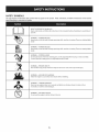 6
6
-
 7
7
-
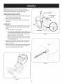 8
8
-
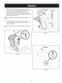 9
9
-
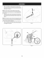 10
10
-
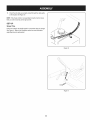 11
11
-
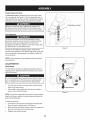 12
12
-
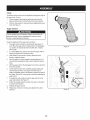 13
13
-
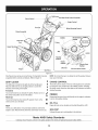 14
14
-
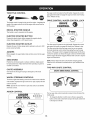 15
15
-
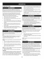 16
16
-
 17
17
-
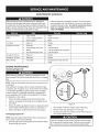 18
18
-
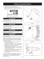 19
19
-
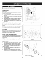 20
20
-
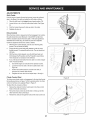 21
21
-
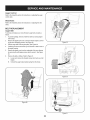 22
22
-
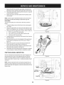 23
23
-
 24
24
-
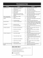 25
25
-
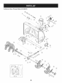 26
26
-
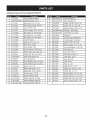 27
27
-
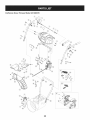 28
28
-
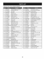 29
29
-
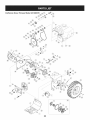 30
30
-
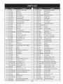 31
31
-
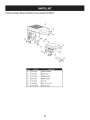 32
32
-
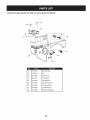 33
33
-
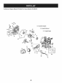 34
34
-
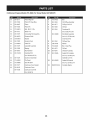 35
35
-
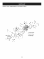 36
36
-
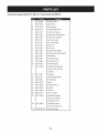 37
37
-
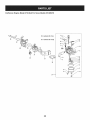 38
38
-
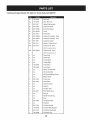 39
39
-
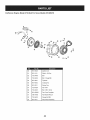 40
40
-
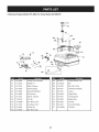 41
41
-
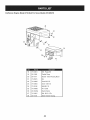 42
42
-
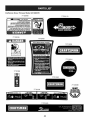 43
43
-
 44
44
-
 45
45
-
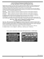 46
46
-
 47
47
-
 48
48
-
 49
49
-
 50
50
-
 51
51
-
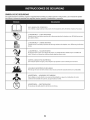 52
52
-
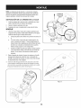 53
53
-
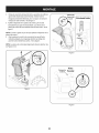 54
54
-
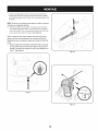 55
55
-
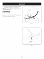 56
56
-
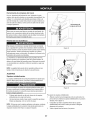 57
57
-
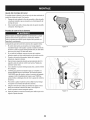 58
58
-
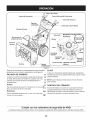 59
59
-
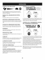 60
60
-
 61
61
-
 62
62
-
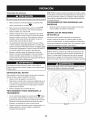 63
63
-
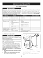 64
64
-
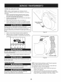 65
65
-
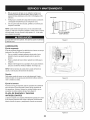 66
66
-
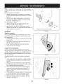 67
67
-
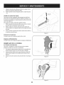 68
68
-
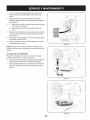 69
69
-
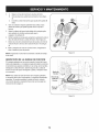 70
70
-
 71
71
-
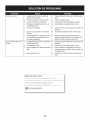 72
72
-
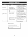 73
73
-
 74
74
-
 75
75
-
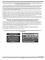 76
76
-
 77
77
-
 78
78
-
 79
79
-
 80
80


MTD 247985370 El manual del propietario
- Categoría
- Lanzadores de nieve
- Tipo
- El manual del propietario
- Este manual también es adecuado para
en otros idiomas
- English: MTD 247985370 Owner's manual
Artículos relacionados
-
MTD 31BH54TG799 El manual del propietario
-
MTD 31AH55TH793 El manual del propietario
-
-
MTD 31AS63EE799 El manual del propietario
-
-
-
MTD 31AS53TF799 El manual del propietario
-
MTD 230 El manual del propietario