ABB NextMove e100 Quick Installation Manual
- Tipo
- Quick Installation Manual

ABB motion control
Quick installation guide
NextMove e100
English . . . . . . . . . . . . . . . . . . . . . . . . . 3
Deutsch. . . . . . . . . . . . . . . . . . . . . . . . 11
Español. . . . . . . . . . . . . . . . . . . . . . . . 19
Français . . . . . . . . . . . . . . . . . . . . . . . 27
Italiano . . . . . . . . . . . . . . . . . . . . . . . . 35
Svenska . . . . . . . . . . . . . . . . . . . . . . . 43
中文. . . . . . . . . . . . . . . . . . . . . . . . . . . 51
LT0305A02
Effective: 2017-06-21
2017 ABB Oy. All rights reserved.
LT0305A01.book Page 1 Wednesday, June 21, 2017 2:10 PM

List of related manuals
You can find manuals and other product documents in PDF format on the Internet. See section Document
library on the Internet on the inside of the back cover. For manuals not available in the Document library,
contact your local ABB representative.
Drive hardware manuals and guides Code (English)
NextMove e100 Motion Controller Installation Manual MN1941WEN
NextMove e100 Wall Chart LT0230...
Mint Basic Programming MN1955
LT0305A01.book Page 2 Wednesday, June 21, 2017 2:10 PM

Quick Installation Guide – NextMove e100 3
Quick Installation Guide – NextMove e100
About this guide
This guide contains very basic information about the mechanical and electrical
installation of the NextMove e100.
Applicability
Applies to all models of NextMove e100, part numbers beginning NXE100...
Related documents
For a list of related documents in English, see the inside of the front cover.
Safety instructions
WARNING! All electrical installation and maintenance work on the product
should be carried out by qualified electricians only.
Never work on the drive, the braking chopper circuit, the motor cable or the motor
when input power is applied to the drive. After disconnecting the input power, always
wait for 5 minutes to let the intermediate circuit capacitors discharge. Always ensure
by measuring that no voltage is actually present.
A rotating permanent magnet motor can generate a dangerous voltage. Lock the
motor shaft mechanically before connecting a permanent magnet motor to the drive,
and before doing any work on a drive system connected to a permanent magnet
motor.
LT0305A01.book Page 3 Wednesday, June 21, 2017 2:10 PM

4 Quick Installation Guide – NextMove e100
Mechanical installation
Fasten the controller to the mounting base using screws through the four mounting
holes.
140
(5.51)
129
(5.08)
170 (6.69)
250 (9.84)
40.3
(1.59)
A
A
B
C
A = 4.5 mm
B = 10 mm
C = 11 mm
All dimensions shown as
mm (inches)
Drawings not to scale
Mounting keyhole and slot detail
Weight:: Approximately 700 g (1.5 lb)
LT0305A01.book Page 4 Wednesday, June 21, 2017 2:10 PM

Quick Installation Guide – NextMove e100 5
Connections
X12 AIN 0-1
& relay
X7 Encoder2
X6 Encoder1
X4 DOUT 8-11
X2 STEP 0-1
5
6
7
2
3
4
1
1
1
X11 DOUT 0-7
1
X10 DIN 0-3
(fast interrupts)
1
X9 DIN 4-11
1
X8 DIN 12-19
1
X13 AOUT 0-3
(demands)
2
X3 STEP 2-3
X5 Encoder0
X1 +24V in
CAN
5
USB
7
2
2
3
4
4
4
Ethernet
Serial
5
6
DIN3
Shield
CREF0
DIN2
Shield
CREF0
DIN1
Shield
CREF0
DIN0
DOUT0
DOUT1
DOUT2
DOUT3
DOUT4
DOUT5
DOUT6
DOUT7
USR V+
USR GND
AIN0+
AIN0-
AGND
AIN1+
AIN1-
Shield
REL COM
REL NC
REL NO
REL COM
1
2
3
4
5
6
7
8
9
10
10
9
8
7
6
5
4
3
2
1
12
11
10
9
8
7
6
5
4
3
2
1
12
11
10
9
8
7
6
5
4
3
2
1
2
1
1
2
3
4
5
6
7
8
9
10
1
2
3
4
5
6
7
8
9
10
1
2
3
4
5
6
7
8
9
10
1
2
3
4
5
6
7
8
9
10
1
2
3
4
5
6
7
8
9
10
11
12
DIN11
DIN10
DIN9
DIN8
DIN7
DIN6
DIN5
DIN4
CREF1
Shield
DIN19
DIN18
DIN17
DIN16
DIN15
DIN14
DIN13
DIN12
CREF2
Shield
CREF2
CREF1
CREF0
USR V+
USR GND
USR V+
DOUT11
DOUT10
DOUT9
DOUT8
Demand0
AGND
Shield
Demand1
AGND
Shield
Demand2
AGND
Shield
Demand3
AGND
Shield
Shield
DIR3+
DIR3-
STEP3+
STEP3-
DGND
Shield
DIR2+
DIR2-
STEP2+
STEP2-
DGND
Shield
DIR3
+5 V
STEP3
(NC)
DGND
Shield
DIR2
+5 V
STEP2
(NC)
DGND
Shield
DIR1+
DIR1-
STEP1+
STEP1-
DGND
Shield
DIR0+
DIR0-
STEP0+
STEP0-
DGND
Shield
DIR1
+5 V
STEP1
(NC)
DGND
Shield
DIR0
+5 V
STEP0
(NC)
DGND
+24 V
0 V
Mating connectors:
Sauro CTF10008
Sauro CTF12008
Sauro CTF02008
9-pin D-type plug (male)
9-pin D-type socket (female)
RJ45 plug
USB type B plug
Tightening torque for terminal block
connections is 0.25 N·m (2.25 lb-in).
Use 60/75 or 75 °C copper (Cu) wire only.
(NC) = Not Connected
For model
NXE100-16xxSx:
LT0305A01.book Page 5 Wednesday, June 21, 2017 2:10 PM

6 Quick Installation Guide – NextMove e100
X1 - Input power
X2, X3 - Stepper control outputs
X4, X11 - Digital outputs
X5, X6, X7 - Encoder inputs
Description Value
Input power
Nominal input voltage
Power consumption
24 V DC (±20%)
50 W (2 A @24 V)
Description Unit NXE100-16xxDx NXE100-16xxSx
Output type RS422 differential
outputs
Darlington
step (pulse) and
direction
Maximum output frequency 5 MHz 500 kHz
Output current 20 mA
(typical)
50 mA
(maximum sink,
per output)
Description Unit Value
USR V+ supply voltage
Nominal
Minimum
VDC
24
12
Output current
Max. source per output, one output on
Max. source per output, all outputs on
Maximum total output current
mA DOUT0-7 DOUT8-11
350 350
62.5 125
500 500
Update interval (Mint) Immediate
Switching time
No load on output
With 7 mA or greater load
100 ms
10 µs
Description Unit Value
Encoder input RS422 A/B Differential, Z index
Maximum input frequency
quadrature
MHz
20
Output power supply to encoders 5V (±5%)
500 mA (maximum total for all axes)
Maximum allowable cable length 30.5 m (100 ft)
LT0305A01.book Page 6 Wednesday, June 21, 2017 2:10 PM

Quick Installation Guide – NextMove e100 7
X8, X9, X10 - Digital inputs
X12 - Analog inputs
X12 - Relay output
X13 - Analog outputs
Description Unit Value
Type Opto-isolated
USR V+ supply voltage
Nominal
Minimum
VDC
24
12
Input voltage
Active
Inactive
VDC
> 12
< 2
Input current
(maximum per input, USR V+ = 24 V)
mA 7
Sampling interval ms 1
Description Unit Value
Type Differential
Common mode voltage range V DC ±10
Input impedance kΩ 120
Maximum input current mA 4.9
Input ADC resolution bits 12 (includes sign bit)
Equivalent resolution (±10 V input) mV ±4.9
Sampling interval µs 500 (both inputs enabled)
250 (one input disabled)
All models Unit All models
Contact rating (resistive) 1 A @ 24 V DC
or
0.25 A @ 30 V AC
Operating time (max) ms 5
Description Unit Value
Type Bipolar
Output voltage range V DC ±10
Output current (per output) mA 2.5
Output DAC resolution bits 12
Equivalent resolution mV ±4.9
Update interval ms 1
LT0305A01.book Page 7 Wednesday, June 21, 2017 2:10 PM

8 Quick Installation Guide – NextMove e100
Serial port
Ethernet interface
CAN interface
Environmental
Unit All models
Signal RS232 or RS485/422 non-isolated
Bit rates baud 9600, 19200, 38400,
57600 (default), 115200
Description Unit Value
Signal 2 twisted pairs, magnetically isolated
Protocols Ethernet POWERLINK & TCP/IP
Bit rates Mbit/s 100
Description Unit Value
Signal 2-wire, isolated
Channels 1
Protocol CANopen
Bit rates Kbit/s
10, 20, 50, 100, 125, 250, 500, 1000
Description Unit
Operating temperature range Min Max
°C
°F
0
+32
+45
+113
Maximum humidity % 80% for temperatures up to 31 °C (87 °F)
decreasingly linearly to 50% relative
humidity at 45 °C (113 °F),
non-condensing
Maximum installation altitude
(above m.s.l.)
m
ft
2000
6560
Shock 10 G according to
IEC 60068-2-6/27 or equivalent
Vibration 1 G, 10-150 Hz according to
IEC 60068-2-6/27 or equivalent
LT0305A01.book Page 8 Wednesday, June 21, 2017 2:10 PM

Quick Installation Guide – NextMove e100 9
24 V DC supply
The NextMove e100 requires a 24 V DC power supply capable of
supplying 2 A continuously. It is recommended that a separate fused
24 V DC supply is provided for the NextMove e100, with the fuse rated
at 4 A maximum. If digital outputs are to be used, a supply will be
required to drive them - see manual MN1941WEN.
USB communication
The NextMove e100 communicates with the host PC using USB 1.1
communication.
Connect the supplied USB cable between the NextMove e100 and the
host PC's USB port (USB 1.1 or USB 2.0).
Ethernet communication
The NextMove e100 exchanges control parameters over Ethernet
POWERLINK.
Connect a CAT5 Ethernet cable between the NextMove e100 E1 or E2
connector and a POWERLINK compatible drive such as MotiFlex e100.
UL checklist
• The controller is to be used in a heated, indoor controlled environment. The
controller must be installed in clean air according to enclosure classification.
Cooling air must be clean, free from corrosive materials and electrically
conductive dust. See manual MN1941WEN for detailed specifications.
• The maximum ambient air temperature is 45 °C (113 °F) at rated current.
• The controller must be installed where the pollution degree according to UL / IEC
60664-1 shall not exceed 2.
Start-up
See manual MN1941WEN.
LT0305A01.book Page 9 Wednesday, June 21, 2017 2:10 PM

10 Quick Installation Guide – NextMove e100
LT0305A01.book Page 10 Wednesday, June 21, 2017 2:10 PM

Kurzinstallationsanleitung – NextMove e100 11
Kurzinstallationsanleitung – NextMove e100
Über diese Anleitung
Diese Anleitung enthält grundlegende Informationen zur mechanischen und
elektrischen Installation des NextMove e100.
Geltungsbereich
Gilt für alle NextMove e100 Varianten, deren Teilenummern mit NXE100... beginnen.
Zugehörige Dokumente
Eine Liste der zugehörigen Dokumente in Englisch ist auf der Rückseite des
Deckblatts dieses Dokuments zu finden.
Sicherheitsanweisungen
WARNUNG!
Alle elektrischen Installations- und Wartungsarbeiten am Produkt
sollten ausschließlich von qualifizierten Elektrofachkräften durchgeführt werden.
Arbeiten Sie keinesfalls am Antrieb, dem Chopperbremsschaltkreis, dem Motorkabel
oder dem Motor, wenn die Stromversorgung am Antrieb anliegt. Nach Unterbrechung
der Stromversorgung warten Sie 5 Minuten, damit sich die
Zwischenkreiskondensatoren entladen können. Stellen Sie durch Messen sicher,
dass keine Spannung mehr anliegt.
Ein sich drehender Motor mit Permanentmagneten kann eine gefährliche Spannung
erzeugen. Verriegeln Sie die Motorwelle mechanisch, bevor Sie einen AC-
Servomotor an den Antrieb anschließen und bevor Sie Arbeiten an einem
Antriebssystem mit angeschlossenem AC-Servomotor ausführen.
LT0305A01.book Page 11 Wednesday, June 21, 2017 2:10 PM

12 Kurzinstallationsanleitung – NextMove e100
Mechanische Installation
Befestigen Sie die Steuerung mit Schrauben in den vier Montagelöchern am
Montagesockel.
140
(5.51)
129
(5.08)
170 (6.69)
250 (9.84)
40.3
(1.59)
A
A
B
C
A = 4.5 mm
B = 10 mm
C = 11 mm
Alle Abmessungen in
mm
Zeichnungen sind nicht maßstabsgetreu
Detailansicht von Befestigungsloch und Schlitz
Gewicht: Ca. 700 g (1,5 lb)
LT0305A01.book Page 12 Wednesday, June 21, 2017 2:10 PM

Kurzinstallationsanleitung – NextMove e100 13
Anschlüsse
X12 AIN 0-1
& relay
X7 Encoder2
X6 Encoder1
X4 DOUT 8-11
X2 STEP 0-1
5
6
7
2
3
4
1
1
1
X11 DOUT 0-7
1
X10 DIN 0-3
(fast interrupts)
1
X9 DIN 4-11
1
X8 DIN 12-19
1
X13 AOUT 0-3
(demands)
2
X3 STEP 2-3
X5 Encoder0
X1 +24V in
CAN
5
USB
7
2
2
3
4
4
4
Ethernet
Serial
5
6
DIN3
Shield
CREF0
DIN2
Shield
CREF0
DIN1
Shield
CREF0
DIN0
DOUT0
DOUT1
DOUT2
DOUT3
DOUT4
DOUT5
DOUT6
DOUT7
USR V+
USR GND
AIN0+
AIN0-
AGND
AIN1+
AIN1-
Shield
REL COM
REL NC
REL NO
REL COM
1
2
3
4
5
6
7
8
9
10
10
9
8
7
6
5
4
3
2
1
12
11
10
9
8
7
6
5
4
3
2
1
12
11
10
9
8
7
6
5
4
3
2
1
2
1
1
2
3
4
5
6
7
8
9
10
1
2
3
4
5
6
7
8
9
10
1
2
3
4
5
6
7
8
9
10
1
2
3
4
5
6
7
8
9
10
1
2
3
4
5
6
7
8
9
10
11
12
DIN11
DIN10
DIN9
DIN8
DIN7
DIN6
DIN5
DIN4
CREF1
Shield
DIN19
DIN18
DIN17
DIN16
DIN15
DIN14
DIN13
DIN12
CREF2
Shield
CREF2
CREF1
CREF0
USR V+
USR GND
USR V+
DOUT11
DOUT10
DOUT9
DOUT8
Demand0
AGND
Shield
Demand1
AGND
Shield
Demand2
AGND
Shield
Demand3
AGND
Shield
Shield
DIR3+
DIR3-
STEP3+
STEP3-
DGND
Shield
DIR2+
DIR2-
STEP2+
STEP2-
DGND
Shield
DIR3
+5 V
STEP3
(NC)
DGND
Shield
DIR2
+5 V
STEP2
(NC)
DGND
Shield
DIR1+
DIR1-
STEP1+
STEP1-
DGND
Shield
DIR0+
DIR0-
STEP0+
STEP0-
DGND
Shield
DIR1
+5 V
STEP1
(NC)
DGND
Shield
DIR0
+5 V
STEP0
(NC)
DGND
+24 V
0 V
Gegenstecker:
Sauro CTF10008
Sauro CTF12008
Sauro CTF02008
9-poliger Stecker, Typ D
9-polige Buchse, Typ D
RJ45-Stecker
USB-Stecker, Typ B
Das Anzugsdrehmoment für die
Klemmleistenanschlüsse beträgt 0,25 Nm (2,25 lb-in).
Nur 60/75 oder 75 °C Kupferdraht (Cu) verwenden.
(NC) = Nicht angeschlossen
Für Variante
NXE100-16xxSx:
LT0305A01.book Page 13 Wednesday, June 21, 2017 2:10 PM

14 Kurzinstallationsanleitung – NextMove e100
X1 - Stromversorgung
X2, X3 - Schrittmotorregelungsausgänge
X4, X11 - Digitalausgänge
X5, X6, X7 - Encodereingänge
Beschreibung Wert
Stromversorgung
Nenneingangsspannung
Stromaufnahme
24 V DC (±20%)
50 W (2 A bei 24 V)
Beschreibung Einheit NXE100-16xxDx NXE100-16xxSx
Ausgangstyp RS422-
Differenzialausgänge
Darlington-
-schritt (Impuls) und
Richtung
Max. Ausgangsfrequenz 5 MHz 500 kHz
Ausgangsstromstärke 20 mA
(typisch)
50 mA
(max. Ableitung,
pro Ausgang)
Beschreibung Einheit Wert
USR V+ Versorgungsspannung
Nennwert
Minimal
VDC
24
12
Ausgangsstromstärke
Max. Quelle pro Ausgang, ein Ausgang an
Max. Quelle pro Ausgang, alle Ausgänge an
Max. gesamte Ausgangsstromstärke
mA DOUT0-7 DOUT8-11
350 350
62,5 125
500 500
Aktualisierungsintervall (Mint) Sofort
Schaltzeit
Keine Last an Ausgang
Mit 7 mA oder größerer Last
100 ms
10 µs
Beschreibung Einheit Wert
Encodereingang RS422 A/B Differenzial, Z Index
Max. Eingangsfrequenz
Quadratur
MHz
20
Ausgangsstromversorgung zu Encodern
5V (±5%)
500 mA (max. insgesamt für alle
Achsen)
Maximale zulässige Kabellänge 30,5 m (100 ft)
LT0305A01.book Page 14 Wednesday, June 21, 2017 2:10 PM

Kurzinstallationsanleitung – NextMove e100 15
X8, X9, X10 - Digitaleingänge
X12 - Analogeingänge
X12 - Relaisausgang
X13 - Analogausgänge
Beschreibung Einheit Wert
Typ Optisch isoliert
USR V+ Versorgungsspannung
Nennwert
Minimal
VDC
24
12
Eingangsspannung
Aktiv
Inaktiv
VDC
> 12
< 2
Eingangsstromstärke
(Maximal pro Eingang, USR V+ = 24 V)
mA 7
Abtastintervall ms 1
Beschreibung Einheit Wert
Typ Differenzial
Gleichtaktspannungsbereich V DC ±10
Eingangsimpedanz kΩ 120
Maximale Eingangsstromstärke mA 4,9
ADC-Eingangsauflösung Bit 12 (einschl. Vorzeichen-Bit)
Äquivalente Auflösung (±10 V Eingang) mV ±4,9
Abtastintervall µs 500 (beide Eingänge aktiviert)
250 (ein Eingang deaktiviert)
Alle Ausführungen Einheit Alle Ausführungen
Kontaktnennwert (resistiv) 1 A bei 24 V DC
oder
0,25 A bei 30 V AC
Schaltdauer (max.) ms 5
Beschreibung Einheit Wert
Typ Bipolar
Ausgangsspannungsbereich V DC ±10
Ausgangsstromstärke (pro Ausgang) mA 2,5
DAC-Ausgangsauflösung Bit 12
Äquivalente Auflösung mV ±4,9
Aktualisierungsintervall ms 1
LT0305A01.book Page 15 Wednesday, June 21, 2017 2:10 PM

16 Kurzinstallationsanleitung – NextMove e100
Serieller Anschluss
Ethernet-Schnittstelle
CAN-Schnittstelle
Umgebungsdaten
Einheit Alle Ausführungen
Signal RS232 oder RS485/422 nicht isoliert
Bitraten Baud 9600, 19200, 38400,
57600 (Standardwert), 115200
Beschreibung Einheit Wert
Signal
2 verdrillte Zweidrahtleitungen, magnetisch
isoliert
Protokolle Ethernet POWERLINK & TCP/IP
Bitraten MBit/s 100
Beschreibung Einheit Wert
Signal 2-litzig, isoliert
Kanäle 1
Protokoll CANopen
Bitraten kBit/s
10, 20, 50, 100, 125, 250, 500, 1000
Beschreibung Einheit
Betriebstemperaturbereich Min. Max.
°C
°F
0
+32
+45
+113
Maximale Luftfeuchtigkeit % 80% bei Temperaturen bis zu 31 °C (87 °F),
linear abnehmend auf 50% relative
Luftfeuchtigkeit bei 45 °C (113 °F) (nicht
kondensierend)
Maximale Aufstellhöhe
(über NN)
m
ft
2000
6560
Stöße 10 G gemäß
IEC 60068-2-6/27 oder gleichwertige
Vibrationen 1 G, 10-150 Hz gemäß
IEC 60068-2-6/27 oder gleichwertige
LT0305A01.book Page 16 Wednesday, June 21, 2017 2:10 PM

Kurzinstallationsanleitung – NextMove e100 17
24 V DC-Stromversorgung
Der NextMove e100 benötigt für den Betrieb eine 24 V DC-
Stromversorgung, die kontinuierlich 2 A liefern kann. Es ist
empfehlenswert, für den NextMove e100 eine eigene, gesicherte
24 V DC-Stromversorgung mit einer Sicherung mit maximal 4 A
Nennwert vorzusehen. Falls Digitalausgänge verwendet werden,
ist für deren Ansteuerung eine Stromversorgung erforderlich –
siehe Handbuch MN1941WDE.
USB-Kommunikation
Das Modell NextMove e100 kommuniziert mit Hilfe von USB 1.1 mit
dem Host-PC.
Schließen Sie das mitgelieferte USB-Kabel zwischen dem USB-
Anschluss des NextMove e100 (Device) und des Host-PC (USB 1.1
oder USB 2.0) an.
Ethernet-Kommunikation
Der NextMove e100 sendet und empfängt Steuerungswerte mittels
Ethernet POWERLINK.
Schließen Sie ein CAT5 Ethernet-Kabel zwischen dem Steckverbinder
E1 oder E2 des NextMove e100 und einem POWERLINK-kompatiblen
Antrieb wie dem MotiFlex e100 an.
UL-Checkliste
• Der Controller ist in einer klimatisierten Umgebung einzusetzen. Der
Controller muss in Reinluft gemäß der Gehäuseklassifikation
installiert werden. Die Kühlluft muss sauber und frei von korrosiven
Stoffen und elektrisch leitendem Staub sein. Genauere Angaben sind dem
Handbuch MN1941WDE zu entnehmen.
• Die maximale Umgebungstemperatur beträgt 45 °C (113 °F) bei
Nennstromstärke.
• Der Controller muss an einer Stelle installiert werden, an dem der
Verschmutzungsgrad nach UL / IEC 60664-1 nicht mehr als 2 beträgt.
Inbetriebsnahme
Siehe Handbuch MN1941WDE.
LT0305A01.book Page 17 Wednesday, June 21, 2017 2:10 PM

18 Kurzinstallationsanleitung – NextMove e100
LT0305A01.book Page 18 Wednesday, June 21, 2017 2:10 PM

Guía de instalación rápida – NextMove e100 19
Guía de instalación rápida – NextMove e100
Acerca de esta guía
Esta guía contiene información muy básica acerca de la instalación mecánica
y eléctrica de NextMove e100.
Aplicación
Esta guía es válida para todos los modelos de NextMove e100 (Referencia
NXE100...)
Documentos relacionados
Para una lista completa de los documentos relacionados vaya a la cara trasera de la
portada (inglés).
Instrucciones de seguridad
¡ATENCIÓN! Todos los trabajos de instalación y mantenimiento del drive
deben ser realizados, única y exclusivamente, por electricistas cualificados.
No realizar nunca trabajos sobre el drive, el circuito de control de freno, el cable del
motor o el motor mientras esté conectado a la fuente de alimentación. Una vez
desconectado de la fuente de alimentación espere siempre 5 minutos para permitir la
descarga de los condensadores en los circuitos intermedios. Asegúrese siempre,
mediante medición, de que no existe tensión activa.
Un motor de imanes permanentes en rotación puede generar un voltaje peligroso.
Enclave mecánicamente el eje del motor antes de conectarlo al drive. Para trabajar
sobre el sistema del drive, una vez conectado al motor, asegúrese de enclavar
mecánicamente el eje del motor.
LT0305A01.book Page 19 Wednesday, June 21, 2017 2:10 PM

20 Guía de instalación rápida – NextMove e100
Instalación mecánica
Fijar el controlador a la base de montaje empleando tornillos a través de los cuatro
taladros de montaje.
140
(5.51)
129
(5.08)
170 (6.69)
250 (9.84)
40.3
(1.59)
A
A
B
C
A = 4.5 mm
B = 10 mm
C = 11 mm
Todas las dimensiones indicadas
en mm (pulgadas)
Cotas sin escala
Detalle de ranura y bocallave de montaje
Peso: Aproximadamente 700 g (1,5 libras)
LT0305A01.book Page 20 Wednesday, June 21, 2017 2:10 PM

Guía de instalación rápida – NextMove e100 21
Conexiones
X12 AIN 0-1
& relay
X7 Encoder2
X6 Encoder1
X4 DOUT 8-11
X2 STEP 0-1
5
6
7
2
3
4
1
1
1
X11 DOUT 0-7
1
X10 DIN 0-3
(fast interrupts)
1
X9 DIN 4-11
1
X8 DIN 12-19
1
X13 AOUT 0-3
(demands)
2
X3 STEP 2-3
X5 Encoder0
X1 +24V in
CAN
5
USB
7
2
2
3
4
4
4
Ethernet
Serial
5
6
DIN3
Shield
CREF0
DIN2
Shield
CREF0
DIN1
Shield
CREF0
DIN0
DOUT0
DOUT1
DOUT2
DOUT3
DOUT4
DOUT5
DOUT6
DOUT7
USR V+
USR GND
AIN0+
AIN0-
AGND
AIN1+
AIN1-
Shield
REL COM
REL NC
REL NO
REL COM
1
2
3
4
5
6
7
8
9
10
10
9
8
7
6
5
4
3
2
1
12
11
10
9
8
7
6
5
4
3
2
1
12
11
10
9
8
7
6
5
4
3
2
1
2
1
1
2
3
4
5
6
7
8
9
10
1
2
3
4
5
6
7
8
9
10
1
2
3
4
5
6
7
8
9
10
1
2
3
4
5
6
7
8
9
10
1
2
3
4
5
6
7
8
9
10
11
12
DIN11
DIN10
DIN9
DIN8
DIN7
DIN6
DIN5
DIN4
CREF1
Shield
DIN19
DIN18
DIN17
DIN16
DIN15
DIN14
DIN13
DIN12
CREF2
Shield
CREF2
CREF1
CREF0
USR V+
USR GND
USR V+
DOUT11
DOUT10
DOUT9
DOUT8
Demand0
AGND
Shield
Demand1
AGND
Shield
Demand2
AGND
Shield
Demand3
AGND
Shield
Shield
DIR3+
DIR3-
STEP3+
STEP3-
DGND
Shield
DIR2+
DIR2-
STEP2+
STEP2-
DGND
Shield
DIR3
+5 V
STEP3
(NC)
DGND
Shield
DIR2
+5 V
STEP2
(NC)
DGND
Shield
DIR1+
DIR1-
STEP1+
STEP1-
DGND
Shield
DIR0+
DIR0-
STEP0+
STEP0-
DGND
Shield
DIR1
+5 V
STEP1
(NC)
DGND
Shield
DIR0
+5 V
STEP0
(NC)
DGND
+24 V
0 V
Conectores para acoplamiento:
Sauro CTF10008
Sauro CTF12008
Sauro CTF02008
Enchufe (macho) tipo D de 9 terminales
Enchufe (hembra) tipo D de 9 terminales
Enchufe RJ45
Enchufe USB tipo B
El par de apriete para las conexiones del
bloque de terminales es de 0,25 N·m
(2,25 libras-pulgada).
Emplear únicamente cable de cobre (Cu)
para 60/75 o 75 °C. (NC) = No Conectado
Para el modelo
NXE100-16xxSx:
LT0305A01.book Page 21 Wednesday, June 21, 2017 2:10 PM

22 Guía de instalación rápida – NextMove e100
X1 - Alimentación de entrada
X2, X3 - Salidas de control paso a paso
X4, X11 - Salidas digitales
X5, X6, X7 - Entradas de encoder
Descripción Valor
Alimentación de entrada
Voltaje de entrada nominal
Consumo de energía
24 V CC (±20%)
50 W (2 A @24 V)
Descripción Unidad NXE100-16xxDx NXE100-16xxSx
Tipo de salida Salidas
diferenciales
RS422
Darlington,
paso (pulso) y
dirección
Frecuencia máxima de salida 5 MHz 500 kHz
Corriente de salida 20 mA
(typicos)
50 mA
(máxima disipación,
por salida)
Descripción Unidad Valor
Voltaje de suministro USR V+
Nominal
Mínimo
VCC
24
12
Corriente de salida
Corriente máxima de salida, una salida
activada
Corriente máxima de salida, todas las
salidas activadas
Corriente de salida total máxima
mA DOUT0-7 DOUT8-11
350 350
62,5 125
500 500
Intervalo de actualización (Mint) Inmediato
Tiempo de conmutación
Salida sin carga
Con carga de 7 mA o superior
100 ms
10 Βµs
Descripción Unidad Valor
Entrada de encoder Diferencial RS422 A/B, índice Z
Frecuencia máxima de entrada
cuadratura
MHz
20
Suministro de energía de salida a los
encoders
5V (±5%)
500 mA (valor total máximo para todos los
ejes)
Longitud máxima del cable permitida 30,5 m (100 ft)
LT0305A01.book Page 22 Wednesday, June 21, 2017 2:10 PM

Guía de instalación rápida – NextMove e100 23
X8, X9, X10 - Entradas digitales
X12 - Entradas analógicas
X12 - Salida de relé
X13 - Salidas analógicas
Descripción Unidad Valor
Tipo Opto-aislada
Voltaje de suministro USR V+
Nominal
Mínimo
VCC
24
12
Voltaje de entrada
Activo
Inactivo
VCC
> 12
< 2
Corriente de entrada
(Máximo por entrada, USR V+ = 24 V)
mA 7
Intervalo de muestreo ms 1
Descripción Unidad Valor
Tipo Diferencial
Rango de voltaje de modo común V CC ±10
Impedancia de entrada kΩ. 120
Corriente máxima de entrada mA 4,9
Resolución de entrada ADC
(Convertidor analógico-digital)
bits 12 (incluye el símbolo de bit)
Resolución equivalente (±10 V
entrada)
mV ±4,9
Intervalo de muestreo µs 500 (ambas entradas habilitadas)
250 (una entrada inhabilitada)
Todos los modelos Unidad Todos los modelos
Clasificación del contacto (resistivo) 1 A @ 24 V CC
o
0,25 A @ 30 V CA
Tiempo de funcionamiento (máximo) ms 5
Descripción Unidad Valor
Tipo Bipolar
Rango de voltaje de salida V CC ±10
Corriente de salida (por salida) mA 2,5
Resolución de salida DAC bits 12
Resolución equivalente mV ±4,9
Intervalo de actualización ms 1
LT0305A01.book Page 23 Wednesday, June 21, 2017 2:10 PM

24 Guía de instalación rápida – NextMove e100
Puerto en serie
Interfaz Ethernet
Interfaz CAN
Ambiental
Unidad Todos los modelos
Señal RS232 o RS485/422 sin aislamiento
Velocidad de transmisión de bits baudio 9600, 19200, 38400,
57600 (por defecto), 115200
Descripción Unidad Valor
Señal
2 pares trenzados, con aislamiento
magnético
Protocolos Ethernet POWERLINK y TCP/IP
Velocidad de transmisión de bits Mbit/s 100
Descripción Unidad Valor
Señal 2 hilos, aislados
Canales 1
Protocolo CANopen
Velocidad de transmisión de bits Kbit/s
10, 20, 50, 100, 125, 250, 500, 1000
Descripción Unidad
Rango de temperatura de
funcionamiento
Mín. Máx.
°C
°F
0
+32
+45
+113
Humedad máxima % 80% para temperaturas de hasta 31 °C
(87 °F) con una disminución lineal hasta
el 50% de humedad relativa a 45 °C
(113 °F), sin-condensación
Altitud de instalación máxima
(por encima del nivel del mar medio)
m
pies
2000
6560
Descarga 10 G de acuerdo con
IEC 60068-2-6/27 o equivalente
Vibración 1 G, 10-150 Hz de acuerdo con
IEC 60068-2-6/27 o equivalente
LT0305A01.book Page 24 Wednesday, June 21, 2017 2:10 PM

Guía de instalación rápida – NextMove e100 25
Alimentación a 24 V CC
NextMove e100 requiere de una alimentación de 24 V CC, capaz de
generar 2A de forma continua. Se recomienda suministrar una
alimentación adjunta a 24 V CC, con fusible de calibre 4 A máximo. Si
se van a utilizar salidas digitales, se requiere de una fuente de
alimentación adicional para gobernarlas. (Ver manual MN1941WES).
Comunicación USB
NextMove e100 se comunica con el PC anfitrión mediante protocolo de
comunicación USB 1.1.
Conecte el cable USB suministrado entre el NextMove e100 y el puerto
USB del PC anfitrión (USB 1.1 o USB 2.0).
Comunicación Ethernet
NextMove e100 intercambia parámetros de control mediante conexión
Ethernet.
Conecte un cable Ethernet CAT5 entre el conector E1 o E2 del
NextMove e100 y un drive POWERLINK compatible como el
MotiFlex e100.
Lista de verificación UL
• El controlador se utilizará en un entorno interior, controlado y
calefactado. Asimismo, deberá instalarse bajo condiciones de aire limpio de
acuerdo con la clasificación del recinto. El aire de refrigeración debe ser limpio y
estar libre de materiales corrosivos y polvo conductor de la electricidad. (Vaya al
manual MN1941WES para más detalle).
• La temperatura ambiente máxima será de 45 °C (113 °F) para corriente nominal.
• El controlador debe instalarse en lugares donde el nivel de contaminación según
la norma UL / IEC 60664-1 no supere el grado 2.
Arranque
Ver manual MN1941WES.
LT0305A01.book Page 25 Wednesday, June 21, 2017 2:10 PM

26 Guía de instalación rápida – NextMove e100
LT0305A01.book Page 26 Wednesday, June 21, 2017 2:10 PM

Guide d'installation rapide – NextMove e100 27
Guide d'installation rapide – NextMove e100
A propos de ce guide
Ce guide contient des informations élémentaires se rapportant à l'installation
mécanique et électrique du NextMove e100.
Produits concernés
Concerne tous les modèles de NextMove e100 dont le numéro de référence
commence par NXE100...
Documents associés
Pour obtenir la liste des documents associés (en anglais), consultez le verso
de la couverture.
Instructions de sécurité
AVERTISSEMENT ! Toutes les procédures d'installation électrique et
d'entretien de ce produit doivent être réalisées exclusivement par des
électriciens qualifiés.
N'intervenez pas sur l'entraînement, le circuit de hacheur de freinage, le câble moteur
ou le moteur lorsque l'alimentation d'entrée est appliquée à l'entraînement. Après
avoir déconnecté l'alimentation d'entrée, patientez toujours 5 minutes pour laisser
le temps aux condensateurs du circuit intermédiaire de se décharger. Mesurez
systématiquement pour vérifier l'absence totale de tension.
Un moteur à aimant permanent en rotation peut générer une tension dangereuse.
Verrouillez mécaniquement l'arbre moteur avant de connecter à l'entraînement un
moteur à aimant permanent, et avant d'intervenir de quelque manière que ce soit
sur un système d'entraînement connecté à un moteur à aimant permanent.
LT0305A01.book Page 27 Wednesday, June 21, 2017 2:10 PM

28 Guide d'installation rapide – NextMove e100
Installation mécanique
Fixez le contrôleur au socle de montage au moyen de vis insérées dans les quatre
trous de montage.
140
(5.51)
129
(5.08)
170 (6.69)
250 (9.84)
40.3
(1.59)
A
A
B
C
A = 4.5 mm
B = 10 mm
C = 11 mm
Toutes les dimensions sont
indiquées en
mm (pouces)
Dessins non mis à l’échelle
Détail d’une encoche et d’une fente de fixation
Poids: 700 g environ (1,5 lb)
LT0305A01.book Page 28 Wednesday, June 21, 2017 2:10 PM

Guide d'installation rapide – NextMove e100 29
Connexions
X12 AIN 0-1
& relay
X7 Encoder2
X6 Encoder1
X4 DOUT 8-11
X2 STEP 0-1
5
6
7
2
3
4
1
1
1
X11 DOUT 0-7
1
X10 DIN 0-3
(fast interrupts)
1
X9 DIN 4-11
1
X8 DIN 12-19
1
X13 AOUT 0-3
(demands)
2
X3 STEP 2-3
X5 Encoder0
X1 +24V in
CAN
5
USB
7
2
2
3
4
4
4
Ethernet
Serial
5
6
DIN3
Shield
CREF0
DIN2
Shield
CREF0
DIN1
Shield
CREF0
DIN0
DOUT0
DOUT1
DOUT2
DOUT3
DOUT4
DOUT5
DOUT6
DOUT7
USR V+
USR GND
AIN0+
AIN0-
AGND
AIN1+
AIN1-
Shield
REL COM
REL NC
REL NO
REL COM
1
2
3
4
5
6
7
8
9
10
10
9
8
7
6
5
4
3
2
1
12
11
10
9
8
7
6
5
4
3
2
1
12
11
10
9
8
7
6
5
4
3
2
1
2
1
1
2
3
4
5
6
7
8
9
10
1
2
3
4
5
6
7
8
9
10
1
2
3
4
5
6
7
8
9
10
1
2
3
4
5
6
7
8
9
10
1
2
3
4
5
6
7
8
9
10
11
12
DIN11
DIN10
DIN9
DIN8
DIN7
DIN6
DIN5
DIN4
CREF1
Shield
DIN19
DIN18
DIN17
DIN16
DIN15
DIN14
DIN13
DIN12
CREF2
Shield
CREF2
CREF1
CREF0
USR V+
USR GND
USR V+
DOUT11
DOUT10
DOUT9
DOUT8
Demand0
AGND
Shield
Demand1
AGND
Shield
Demand2
AGND
Shield
Demand3
AGND
Shield
Shield
DIR3+
DIR3-
STEP3+
STEP3-
DGND
Shield
DIR2+
DIR2-
STEP2+
STEP2-
DGND
Shield
DIR3
+5 V
STEP3
(NC)
DGND
Shield
DIR2
+5 V
STEP2
(NC)
DGND
Shield
DIR1+
DIR1-
STEP1+
STEP1-
DGND
Shield
DIR0+
DIR0-
STEP0+
STEP0-
DGND
Shield
DIR1
+5 V
STEP1
(NC)
DGND
Shield
DIR0
+5 V
STEP0
(NC)
DGND
+24 V
0 V
Connecteurs d’accouplement :
Sauro CTF10008
Sauro CTF12008
Sauro CTF02008
Fiche type D 9 broches (mâle)
Prise type D 9 broches (femelle)
Fiche RJ45
Fiche USB type B
Le couple de serrage des connecteurs de
bornier est de 0,25 N.m (2,25 lb-in).
Utilisez uniquement des fils en cuivre (Cu)
60/75 ou 75 °C. (NC) = Non connecté
Pour le modèle
NXE100-16xxSx:
LT0305A01.book Page 29 Wednesday, June 21, 2017 2:10 PM

30 Guide d'installation rapide – NextMove e100
X1 - Alimentation d’entrée
X2, X3 - Sorties de commande de moteur pas à pas
X4, X11 - Sorties TOR
X5, X6, X7 - Entrées d'encodeur
Description Valeur
Alimentation d’entrée
Tension nominale d’entrée
Consommation
24 V c.c. (±20 %)
50 W (2 A à 24 V)
Description Unité NXE100-16xxDx NXE100-16xxSx
Type de sortie Sorties différentielles
RS422
Darlington,
pas (impulsion) et
direction
Fréquence de sortie maximum 5 MHz 500 kHz
Courant de sortie 20 mA
(typique)
50 mA
(écoulement
maximum,
par sortie)
Description Unité Valeur
USR V+ tension d’alimentation
Puissance
Minimale
Vc.c.
24
12
Courant de sortie
Source max. par sortie, une sortie
activée
Source max. par sortie, toutes les
sorties activées
Courant de sortie total maximum
mA DOUT0-7 DOUT8-11
350 350
62,5 125
500 500
Intervalle de mise à jour (Mint) Mise à jour immédiate
Temps de commutation
Pas de charge sur la sortie
Avec une charge de 7 mA ou
supérieure
100 ms
10 µs
Description Unité Valeur
Entrée d'encodeur RS422 A/B différentielle, index Z
Fréquence maximale en entrée
(quadrature)
MHz
20
Alimentation fournie aux encodeurs
5V (±5%)
500 mA (total au maximum pour tous les
axes)
Longueur maximale de câble
autorisée
30,5 m (100 ft)
LT0305A01.book Page 30 Wednesday, June 21, 2017 2:10 PM

Guide d'installation rapide – NextMove e100 31
X8, X9, X10 - Entrées TOR
X12 - Entrées analogiques
X12 - Sortie de relais
X13 - Sorties analogiques
Description Unité Valeur
Type Opto-isolée
USR V+ tension d’alimentation
Nominale
Minimale
Vc.c.
24
12
Tension d’entrée
Activé
Désactivé
Vc.c.
> 12
< 2
Courant d’entrée
(maximum par entrée, USR V+ = 24 V
mA 7
Intervalle d’échantillonnage ms 1
Description Unité Valeur
Type Différentielle
Plage de tension de mode commun V c.c. ±10
Impédance d’entrée kΩ 120
Courant d’entrée maximum mA 4,9
Résolution d’entrée du convertisseur
analogique-numérique
bits 12 (avec signe)
Résolution équivalente (entrée ±10 V) mV ±4,9
Intervalle d’échantillonnage µs 500 (deux entrées activées)
250 (une entrée désactivée)
Tous les modèles Unité Tous les modèles
Pouvoir de coupure (résistif) 1 A à 24 V c.c.
ou
0,25 A à 30 V c.a.
Temps de fonctionnement (max) ms 5
Description Unité Valeur
Type Bipolaire
Plage de tension de sortie V c.c. ±10
Courant de sortie (par sortie) mA 2,5
Résolution de sortie du
convertisseur analogique
bits 12
Résolution équivalente mV ±4,9
Intervalle de mise à jour ms 1
LT0305A01.book Page 31 Wednesday, June 21, 2017 2:10 PM

32 Guide d'installation rapide – NextMove e100
Port série
Interface Ethernet
Interface CAN
Conditions ambiantes
Unité Tous les modèles
Signal RS232 ou RS485/422, non-isolé
Débit baud 9600, 19200, 38400,
57600 (par défaut), 115200
Description Unité Valeur
Signal
2 paires torsadées, isolées
magnétiquement
Protocoles Ethernet POWERLINK et TCP/IP
Débit Mbit/s 100
Description Unité Valeur
Signal bifilaire, isolé
Voies 1
Protocole CANopen
Débit Kbit/s
10, 20, 50, 100, 125, 250, 500, 1000
Description Unité
Plage de température d’exploitation Min. Max.
°C
°F
0
+32
+45
+113
Humidité maximale % 80 % pour les températures jusqu’à 31 °C
(87 °F), avec diminution linéaire jusqu’à
une humidité relative de 50 % à 45 °C
(113 °F), sans-condensation
Altitude maximale d’installation
(au-dessus du niveau moyen de la mer)
m
ft
2000
6560
Chocs 10 G conformément à
IEC 60068-2-6/27 ou équivalent
Vibrations 1 G, 10-150 Hz conformément à
IEC 60068-2-6/27 ou équivalent
LT0305A01.book Page 32 Wednesday, June 21, 2017 2:10 PM

Guide d'installation rapide – NextMove e100 33
Alimentation 24 V c.c.
Le NextMove e100 nécessite une alimentation 24 V c.c. capable de
fournir 2 A en fonctionnement continu. Il est recommandé de fournir
séparément une alimentation de 24 V c.c. à fusible pour le
NextMove e100, avec un fusible de 4 A maximum. Si vous prévoyez
d’utiliser des sorties numériques, une alimentation sera requise pour
les piloter – voir le manuel MN1941WFR.
Communication USB
Le NextMove e100 communique avec le PC hôte par le biais
d'une communication USB 1.1.
Connectez le câble USB fourni entre le NextMove e100 et le
port USB du PC hôte (USB 1.1 ou USB 2.0).
Communication Ethernet
Le NextMove e100 échange les paramètres de commandes par
Ethernet POWERLINK.
Connectez un câble Ethernet CAT5 entre le connecteur E1 ou E2 du
NextMove e100 et un contrôleur compatible POWERLINK, tel que le
MotiFlex e100.
Liste de contrôle UL
• Le contrôleur doit être utilisé à l'intérieur, dans un environnement
chauffé et contrôlé. Le contrôleur doit être installé à l'air propre, conformément à
la classification du boîtier. L'air de refroidissement doit être propre, dépourvu
de matériaux corrosifs et de poussière conductrice d'électricité. Voir le manuel
MN1941WFR pour les caractéristiques techniques détaillées.
• La température maximum de l'air ambiant est de 45 °C (113 °F) à l'intensité
nominale.
• Le contrôleur doit être installé là où le niveau de pollution, conformément à la
norme UL / IEC 60664-1, ne dépasse pas 2.
Démarrage
Voir le manuel MN1941WFR.
LT0305A01.book Page 33 Wednesday, June 21, 2017 2:10 PM

34 Guide d'installation rapide – NextMove e100
LT0305A01.book Page 34 Wednesday, June 21, 2017 2:10 PM

Guida d'installazione rapida – NextMove e100 35
Guida d'installazione rapida – NextMove e100
Informazioni sulla presente guida
In questa guida sono riportate informazioni di base sull'installazione meccanica
ed elettrica di NextMove e100.
Ambito di applicazione
Si applica a tutti i modelli NextMove e100 il cui codice inizia con NXE100...
Documenti correlati
Per un elenco dei documenti correlati in inglese, vedere l'interno della copertina.
Istruzioni per la sicurezza
AVVERTENZA! Tutti gli interventi di manutenzione e installazione elettrica
sul prodotto devono essere eseguiti esclusivamente da elettricisti qualificati.
Non eseguire mai alcun intervento sul drive, sul circuito del chopper di frenatura,
sul cavo del motore o sul motore stesso quando il drive è collegato all'alimentazione.
Una volta scollegata l'alimentazione, attendere sempre 5 minuti per lasciar scaricare
i condensatori del circuito intermedio. Verificare sempre misurando che non sia
presente tensione.
Un motore a magnete permanente in rotazione può generare una tensione
pericolosa. Prima di collegare un motore a magnete permanente al drive e prima di
eseguire qualsiasi intervento su un sistema di trasmissione collegato a un motore a
magnete permanente, bloccare meccanicamente l'albero motore.
LT0305A01.book Page 35 Wednesday, June 21, 2017 2:10 PM

36 Guida d'installazione rapida – NextMove e100
Installazione meccanica
Serrare il controller alla base con viti nei quattro fori di montaggio.
140
(5.51)
129
(5.08)
170 (6.69)
250 (9.84)
40.3
(1.59)
A
A
B
C
A = 4.5 mm
B = 10 mm
C = 11 mm
Tutte le dimensioni sono riportate in
mm (pollici)
Disegni non in scala
Dettagli fessura per chiavetta di montaggio e slot
Peso: Circa 700 g (1,5 lb)
LT0305A01.book Page 36 Wednesday, June 21, 2017 2:10 PM

Guida d'installazione rapida – NextMove e100 37
Collegamenti
X12 AIN 0-1
& relay
X7 Encoder2
X6 Encoder1
X4 DOUT 8-11
X2 STEP 0-1
5
6
7
2
3
4
1
1
1
X11 DOUT 0-7
1
X10 DIN 0-3
(fast interrupts)
1
X9 DIN 4-11
1
X8 DIN 12-19
1
X13 AOUT 0-3
(demands)
2
X3 STEP 2-3
X5 Encoder0
X1 +24V in
CAN
5
USB
7
2
2
3
4
4
4
Ethernet
Serial
5
6
DIN3
Shield
CREF0
DIN2
Shield
CREF0
DIN1
Shield
CREF0
DIN0
DOUT0
DOUT1
DOUT2
DOUT3
DOUT4
DOUT5
DOUT6
DOUT7
USR V+
USR GND
AIN0+
AIN0-
AGND
AIN1+
AIN1-
Shield
REL COM
REL NC
REL NO
REL COM
1
2
3
4
5
6
7
8
9
10
10
9
8
7
6
5
4
3
2
1
12
11
10
9
8
7
6
5
4
3
2
1
12
11
10
9
8
7
6
5
4
3
2
1
2
1
1
2
3
4
5
6
7
8
9
10
1
2
3
4
5
6
7
8
9
10
1
2
3
4
5
6
7
8
9
10
1
2
3
4
5
6
7
8
9
10
1
2
3
4
5
6
7
8
9
10
11
12
DIN11
DIN10
DIN9
DIN8
DIN7
DIN6
DIN5
DIN4
CREF1
Shield
DIN19
DIN18
DIN17
DIN16
DIN15
DIN14
DIN13
DIN12
CREF2
Shield
CREF2
CREF1
CREF0
USR V+
USR GND
USR V+
DOUT11
DOUT10
DOUT9
DOUT8
Demand0
AGND
Shield
Demand1
AGND
Shield
Demand2
AGND
Shield
Demand3
AGND
Shield
Shield
DIR3+
DIR3-
STEP3+
STEP3-
DGND
Shield
DIR2+
DIR2-
STEP2+
STEP2-
DGND
Shield
DIR3
+5 V
STEP3
(NC)
DGND
Shield
DIR2
+5 V
STEP2
(NC)
DGND
Shield
DIR1+
DIR1-
STEP1+
STEP1-
DGND
Shield
DIR0+
DIR0-
STEP0+
STEP0-
DGND
Shield
DIR1
+5 V
STEP1
(NC)
DGND
Shield
DIR0
+5 V
STEP0
(NC)
DGND
+24 V
0 V
Connettori di accoppiamento:
Sauro CTF10008
Sauro CTF12008
Sauro CTF02008
Presa a 9 pin tipo D (maschio)
Presa a 9 pin tipo D (femmina)
Presa RJ45
Presa USB tipo B
La coppia di serraggio per i collegamenti
del blocco terminale è 0,25 Nm (2,25 lb-in).
Utilizzare esclusivamente filo in rame (Cu)
60/75 o 75 °C. (NC) = non collegato
Per modello
NXE100-16xxSx:
LT0305A01.book Page 37 Wednesday, June 21, 2017 2:10 PM

38 Guida d'installazione rapida – NextMove e100
X1 - Potenza di ingresso
X2, X3 - Uscite di controllo passo-passo
X4, X11 - Uscite digitali
X5, X6, X7 - Ingressi encoder
Descrizione Valore
Potenza di ingresso
Tensione di ingresso nominale
Consumo d'energia
24 V CC (±20%)
50 W (2 A a 24 V)
Descrizione Unità NXE100-16xxDx NXE100-16xxSx
Tipo di uscita Uscite differenziali
RS422
Darlington
step (impulso) e
direzione
Frequenza massima di uscita 5 MHz 500 kHz
Corrente di uscita 20 mA
(tipica)
50 mA
(dissipazione
massima,
per uscita)
Descrizione Unità Valore
Tensione di alimentazione USR V+
Nominale
Minima
VCC
24
12
Corrente di uscita
Origine max. per uscita, un'uscita attiva
Origine max. per uscita, tutte le uscite
attive
Massima corrente di uscita totale
mA DOUT0-7 DOUT8-11
350 350
62,5 125
500 500
Intervallo di aggiornamento (Mint) Immediato
Tempo di commutazione
Nessun carico di uscita
Con carico di 7 mA o superiore
100 ms
10 µs
Descrizione Unità Valore
Ingresso encoder Differenziale RS422 A/B, z-index
Massima frequenza di ingresso
quadratura
MHz
20
Alimentazione di uscita per encoder 5V (±5%)
500 mA (totale massimo per tutti gli assi)
Lunghezza massima consentita del
cavo
30,5 m (100 ft)
LT0305A01.book Page 38 Wednesday, June 21, 2017 2:10 PM

Guida d'installazione rapida – NextMove e100 39
X8, X9, X10 - Ingressi digitali
X12 - Ingressi analogici
X12 - Uscita relé
X13 - Uscite analogiche
Descrizione Unità Valore
Tipo Optoisolato
Tensione di alimentazione USR V+
Nominale
Minima
VCC
24
12
Tensione di ingresso
Attiva
Inattiva
VCC
> 12
< 2
Corrente ingresso
(massima per ingresso,
USR V+ = 24 V)
mA 7
Intervallo di campionamento ms 1
Descrizione Unità Valore
Tipo Differenziale
Intervallo di tensione di modo
comune
VCC ±10
Impedenza di ingresso kΩ 120
Massima corrente ingresso mA 4,9
Risoluzione ingresso ADC bit 12 (include il bit del segno)
Risoluzione equivalente
(ingresso ±10 V)
mV ±4,9
Intervallo di campionamento µs 500 (entrambi gli ingressi attivati)
250 (un ingresso disabilitato)
Tutti i modelli Unità Tutti i modelli
Corrente di contatto (resistiva) 1 A @ 24 V CC
oppure
0,25 A a 30 V CA
Tempo di operatività (max) ms 5
Descrizione Unità Valore
Tipo Bipolare
Intervallo di tensione d'uscita V CC ±10
Corrente di uscita (per uscita) mA 2,5
Risoluzione uscita DAC bit 12
Risoluzione equivalente mV ±4,9
Intervallo di aggiornamento ms 1
LT0305A01.book Page 39 Wednesday, June 21, 2017 2:10 PM

40 Guida d'installazione rapida – NextMove e100
Porta seriale
Interfaccia Ethernet
Interfaccia CAN
Dati ambientali
Unità Tutti i modelli
Segnale RS232 o RS485/422 non isolata
Bit rate baud 9600, 19200, 38400,
57600 (predefinito), 115200
Descrizione Unità Valore
Segnale
2 doppini intrecciati, isolati
magneticamente
Protocolli Ethernet POWERLINK e TCP/IP
Bit rate Mbit/s 100
Descrizione Unità Valore
Segnale a 2 fili, isolato
Canali 1
Protocollo CANopen
Bit rate Kbit/s
10, 20, 50, 100, 125, 250, 500, 1000
Descrizione Unità
Intervallo temperatura di operatività Min Max
°C
°F
0
+32
+45
+113
Umidità massima % 80% per temperature fino a 31 °C (87 °F)
decrescendo in modo lineare fino al 50% di
umidità relativa con una temperatura di
45 °C (113 °F), senza condensa
Altitudine di installazione massima
(s.l.m.)
m
ft
2000
6560
Urto 10 G ai sensi della norma
IEC 60068-2-6/27 o equivalente
Vibrazioni 1 G, 10-150 Hz ai sensi della norma
IEC 60068-2-6/27 o equivalente
LT0305A01.book Page 40 Wednesday, June 21, 2017 2:10 PM

Guida d'installazione rapida – NextMove e100 41
Alimentazione 24 V CC
Per NextMove e100 occorre un'alimentazione a 24 V CC capace di
fornire continuamente 2 A. Si consiglia di utilizzare un'alimentazione a
24 V CC con fusibile separata per NextMove e100, con il fusibile di 4 A
nominali massimi. Se occorre utilizzare uscite digitali, sarà necessario
alimentarle (vedere il manuale MN1941WIT).
Comunicazione USB
NextMove e100 e il PC host comunicano utilizzando la comunicazione
USB 1.1.
Utilizzando il cavo USB fornito, collegare NextMove e100 alla porta
USB del PC host (USB 1.1 o USB 2.0).
Comunicazione Ethernet
NextMove e100 scambia parametri di controllo tramite Ethernet
POWERLINK.
Utilizzando un cavo Ethernet CAT5, collegare il connettore E1 o E2 di
NextMove e100 a un drive compatibile POWERLINK come
MotiFlex e100.
Lista di controllo UL
• Utilizzare il controller in un ambiente interno a riscaldamento
controllato. Installare il controller in aria pulita secondo la
classificazione dell'involucro. L'aria di raffreddamento deve essere pulita, priva di
materiali corrosivi e polveri elettricamente conduttive. Vedere il manuale
MN1941WIT per specifiche dettagliate.
• La temperatura massima dell'aria ambientale è 45 °C (113 °F) a corrente
nominale.
• Installare il controller in luoghi in cui il grado di inquinamento ai sensi della norma
UL / IEC 60664-1 non sia superiore a 2.
Avvio
Vedere il manuale MN1941WIT.
LT0305A01.book Page 41 Wednesday, June 21, 2017 2:10 PM

42 Guida d'installazione rapida – NextMove e100
LT0305A01.book Page 42 Wednesday, June 21, 2017 2:10 PM

Snabbinstallationshandbok – NextMove e100 43
Snabbinstallationshandbok – NextMove e100
Om användarhandboken
Den här handboken innehåller grundläggande information om mekanisk och elektrisk
installation av NextMove e100.
Användning
Gäller för alla NextMove e100-modeller vars artikelnummer börjar med NXE100.
Tillhörande dokument
En lista över tillhörande dokument på engelska finns på insidan av omslaget.
Säkerhetsanvisningar
VARNING: Allt elektriskt installations- och underhållsarbete på produkten får
endast utföras av behöriga elektriker.
Arbeta aldrig på enheten, bromschopperkretsen, motorkabeln eller motorn när
enhetens ingångsström är aktiverad. När du har kopplat ur ingångsströmmen måste
du alltid vänta fem minuter tills mellankretskondensatorerna laddas ur. Gör alltid
mätningar för att se till att det inte finns någon spänning.
En roterande permanentmagnetmotor kan generera farlig spänning. Lås motoraxeln
mekaniskt innan du ansluter en permanentmagnetmotor till enheten och innan du
utför något arbete på ett drivsystem som är anslutet till en permanentmagnetmotor.
LT0305A01.book Page 43 Wednesday, June 21, 2017 2:10 PM

44 Snabbinstallationshandbok – NextMove e100
Mekanisk installation
Fäst styrenheten på monteringsbasen med skruvar genom de fyra monteringshålen.
140
(5.51)
129
(5.08)
170 (6.69)
250 (9.84)
40.3
(1.59)
A
A
B
C
A = 4.5 mm
B = 10 mm
C = 11 mm
Alla mått visas i
mm (tum)
Ritningarna är inte skalenliga
Detaljbild på montering av nyckelhål och fack
Vikt: cirka 700 g (1.5 lb)
LT0305A01.book Page 44 Wednesday, June 21, 2017 2:10 PM

Snabbinstallationshandbok – NextMove e100 45
Anslutningar
X12 AIN 0-1
& relay
X7 Encoder2
X6 Encoder1
X4 DOUT 8-11
X2 STEP 0-1
5
6
7
2
3
4
1
1
1
X11 DOUT 0-7
1
X10 DIN 0-3
(fast interrupts)
1
X9 DIN 4-11
1
X8 DIN 12-19
1
X13 AOUT 0-3
(demands)
2
X3 STEP 2-3
X5 Encoder0
X1 +24V in
CAN
5
USB
7
2
2
3
4
4
4
Ethernet
Serial
5
6
DIN3
Shield
CREF0
DIN2
Shield
CREF0
DIN1
Shield
CREF0
DIN0
DOUT0
DOUT1
DOUT2
DOUT3
DOUT4
DOUT5
DOUT6
DOUT7
USR V+
USR GND
AIN0+
AIN0-
AGND
AIN1+
AIN1-
Shield
REL COM
REL NC
REL NO
REL COM
1
2
3
4
5
6
7
8
9
10
10
9
8
7
6
5
4
3
2
1
12
11
10
9
8
7
6
5
4
3
2
1
12
11
10
9
8
7
6
5
4
3
2
1
2
1
1
2
3
4
5
6
7
8
9
10
1
2
3
4
5
6
7
8
9
10
1
2
3
4
5
6
7
8
9
10
1
2
3
4
5
6
7
8
9
10
1
2
3
4
5
6
7
8
9
10
11
12
DIN11
DIN10
DIN9
DIN8
DIN7
DIN6
DIN5
DIN4
CREF1
Shield
DIN19
DIN18
DIN17
DIN16
DIN15
DIN14
DIN13
DIN12
CREF2
Shield
CREF2
CREF1
CREF0
USR V+
USR GND
USR V+
DOUT11
DOUT10
DOUT9
DOUT8
Demand0
AGND
Shield
Demand1
AGND
Shield
Demand2
AGND
Shield
Demand3
AGND
Shield
Shield
DIR3+
DIR3-
STEP3+
STEP3-
DGND
Shield
DIR2+
DIR2-
STEP2+
STEP2-
DGND
Shield
DIR3
+5 V
STEP3
(NC)
DGND
Shield
DIR2
+5 V
STEP2
(NC)
DGND
Shield
DIR1+
DIR1-
STEP1+
STEP1-
DGND
Shield
DIR0+
DIR0-
STEP0+
STEP0-
DGND
Shield
DIR1
+5 V
STEP1
(NC)
DGND
Shield
DIR0
+5 V
STEP0
(NC)
DGND
+24 V
0 V
Kortanslutningar:
Sauro CTF10008
Sauro CTF12008
Sauro CTF02008
9-stiftsplugg typ D (hane)
9-stiftskontakt typ D (hona)
RJ45-plugg
USB-plugg typ B
Åtdragningsmomentet för
terminalblocksanslutningarna är 0,25 Nm.
Använd endast 60/75 or 75 °C-
kopparledningar (NC) = Ej ansluten
För modellen
NXE100-16xxSx:
LT0305A01.book Page 45 Wednesday, June 21, 2017 2:10 PM

46 Snabbinstallationshandbok – NextMove e100
X1 - 24 V likström-försörjning
X2, X3 - Stegmotorstyrutgångar
X4, X11 - Digitala utgångar
X5, X6, X7 - Motoråterkoppling
Description Value
Input power
Nominal input voltage
Power consumption
24 V DC (±20%)
50 W (2 A @24 V)
Description Unit NXE100-16xxDx NXE100-16xxSx
Output type RS422 differential
outputs
Darlington
step (pulse) and
direction
Maximum output frequency 5 MHz 500 kHz
Output current 20 mA
(typical)
50 mA
(maximum sink,
per output)
Description Unit Value
USR V+ supply voltage
Nominal
Minimum
VDC
24
12
Output current
Max. source per output, one output on
Max. source per output, all outputs on
Maximum total output current
mA DOUT0-7 DOUT8-11
350 350
62.5 125
500 500
Update interval (Mint) Immediate
Switching time
No load on output
With 7 mA or greater load
100 ms
10 µs
Description Unit Value
Encoder input RS422 A/B Differential, Z index
Maximum input frequency
quadrature
MHz
20
Output power supply to encoders 5V (±5%)
500 mA (maximum total for all axes)
Maximum allowable cable length 30.5 m (100 ft)
LT0305A01.book Page 46 Wednesday, June 21, 2017 2:10 PM

Snabbinstallationshandbok – NextMove e100 47
X8, X9, X10 - Digitala ingångar
X12 - Analoga ingångar
X12 - Reläutgång
X13 - Analoga utgångar
Description Unit Value
Type Opto-isolated
USR V+ supply voltage
Nominal
Minimum
VDC
24
12
Input voltage
Active
Inactive
VDC
> 12
< 2
Input current
(maximum per input, USR V+ = 24 V)
mA 7
Sampling interval ms 1
Description Unit Value
Type Differential
Common mode voltage range V DC ±10
Input impedance kΩ 120
Maximum input current mA 4.9
Input ADC resolution bits 12 (includes sign bit)
Equivalent resolution (±10 V input) mV ±4.9
Sampling interval µs 500 (both inputs enabled)
250 (one input disabled)
All models Unit All models
Contact rating (resistive) 1 A @ 24 V DC
or
0.25 A @ 30 V AC
Operating time (max) ms 5
Description Unit Value
Type Bipolar
Output voltage range V DC ±10
Output current (per output) mA 2.5
Output DAC resolution bits 12
Equivalent resolution mV ±4.9
Update interval ms 1
LT0305A01.book Page 47 Wednesday, June 21, 2017 2:10 PM

48 Snabbinstallationshandbok – NextMove e100
Serieport
Ethernet-kommunikation
CAN-kommunikation
Miljövillkor
Unit All models
Signal RS232 or RS485/422 non-isolated
Bit rates baud 9600, 19200, 38400,
57600 (default), 115200
Description Unit Value
Signal 2 twisted pairs, magnetically isolated
Protocols Ethernet POWERLINK & TCP/IP
Bit rates Mbit/s 100
Description Unit Value
Signal 2-wire, isolated
Channels 1
Protocol CANopen
Bit rates Kbit/s
10, 20, 50, 100, 125, 250, 500, 1000
Description Unit
Operating temperature range Min Max
°C
°F
0
+32
+45
+113
Maximum humidity % 80% for temperatures up to 31 °C (87 °F)
decreasingly linearly to 50% relative
humidity at 45 °C (113 °F),
non-condensing
Maximum installation altitude
(above m.s.l.)
m
ft
2000
6560
Shock 10 G according to
IEC 60068-2-6/27 or equivalent
Vibration 1 G, 10-150 Hz according to
IEC 60068-2-6/27 or equivalent
LT0305A01.book Page 48 Wednesday, June 21, 2017 2:10 PM

Snabbinstallationshandbok – NextMove e100 49
24 V likströmskälla
NextMove e100 kräver en strömkälla på 24 V likström som kan
leverera 2 A kontinuerligt. Vi rekommenderar att du använder en
separat strömkälla på 24 V likström med säkring för NextMove e100
med en säkring på högst 4 A. Om digitala utgångar ska användas krävs
en strömkälla som driver dem – se bruksanvisningen MN1941WSV.
USB-kommunikation
NextMove e100 kommunicerar med värddatorn via USB1.1-
kommunikation.
Anslut den medföljande USB-kabeln mellan NextMove e100 och
värddatorns USB-port (USB1.1 eller USB2.0).
Ethernet-kommunikation
NextMove e100 utbyter kontrollparametrar över Ethernet POWERLINK.
Anslut en CAT5 Ethernet-kabel mellan kontakterna NextMove e100 E1
eller E2 och en POWERLINK-kompatibel enhet, t.ex. MotiFlex e100.
UL-checklista
• Styrenheten ska användas i en kontrollerad uppvärmd inomhusmiljö. Styrenheten
måste installeras i ren luft i enlighet med klassificeringen på inneslutningen.
Kylluften måste vara ren, fri från frätande material och elektriskt ledande damm.
Detaljerade specifikationer finns i bruksanvisningen MN1941WSV.
• Den högsta tillåtna lufttemperaturen är 45 °C.
• Styrenheten måste installeras där föroreningsgrad enligt UL / IEC 60664-1 får inte
överstiga 2.
Starta
Se bruksanvisningen MN1941WSV.
LT0305A01.book Page 49 Wednesday, June 21, 2017 2:10 PM

50 Snabbinstallationshandbok – NextMove e100
LT0305A01.book Page 50 Wednesday, June 21, 2017 2:10 PM

快速安装指南
– NextMove e100 51
快速安装指南 – NextMove e100
关于该指南
该指南包含有关 NextMove e100 机械和电气安装的最基本的信息。
适用范围
适用于所有型号的 NextMove e100 ,部件编码开头为 NXE100...
相关文档
相关英文文档列表,请参见封面内页。
安全须知
警告! 只有合格的电气技师才可对驱动器进行电气安装和维护。
当驱动器连接有输入电源时不能在驱动器、制动斩波器电路、电机电缆或电机上进行
任何作业。断开输入电源之后,必须至少等待 5 分钟,使中间电路电容器放电完毕。
始终要通过测量确认已不存在任何电压。
旋转的永磁电机可以产生危险的电压。在永磁电机与驱动器连接之前以及在接有永磁
电机的传动系统上进行任何工作之前,应将电机轴机械锁死。
LT0305A01.book Page 51 Wednesday, June 21, 2017 2:10 PM

52
快速安装指南
– NextMove e100
机械安装
用安装螺丝通过四个安装孔将控制器固定到安装座上。
140
(5.51)
129
(5.08)
170 (6.69)
250 (9.84)
40.3
(1.59)
A
A
B
C
A = 4.5 mm
B = 10 mm
C = 11 mm
所有尺寸均以
mm (英寸)表示
图纸未按比例
安装锁眼和插槽详情
重量 : 约 700 g ( 1.5 lb )
LT0305A01.book Page 52 Wednesday, June 21, 2017 2:10 PM

快速安装指南
– NextMove e100 53
连接
X12 AIN 0-1
& relay
X7 Encoder2
X6 Encoder1
X4 DOUT 8-11
X2 STEP 0-1
5
6
7
2
3
4
1
1
1
X11 DOUT 0-7
1
X10 DIN 0-3
(fast interrupts)
1
X9 DIN 4-11
1
X8 DIN 12-19
1
X13 AOUT 0-3
(demands)
2
X3 STEP 2-3
X5 Encoder0
X1 +24V in
CAN
5
USB
7
2
2
3
4
4
4
Ethernet
Serial
5
6
DIN3
Shield
CREF0
DIN2
Shield
CREF0
DIN1
Shield
CREF0
DIN0
DOUT0
DOUT1
DOUT2
DOUT3
DOUT4
DOUT5
DOUT6
DOUT7
USR V+
USR GND
AIN0+
AIN0-
AGND
AIN1+
AIN1-
Shield
REL COM
REL NC
REL NO
REL COM
1
2
3
4
5
6
7
8
9
10
10
9
8
7
6
5
4
3
2
1
12
11
10
9
8
7
6
5
4
3
2
1
12
11
10
9
8
7
6
5
4
3
2
1
2
1
1
2
3
4
5
6
7
8
9
10
1
2
3
4
5
6
7
8
9
10
1
2
3
4
5
6
7
8
9
10
1
2
3
4
5
6
7
8
9
10
1
2
3
4
5
6
7
8
9
10
11
12
DIN11
DIN10
DIN9
DIN8
DIN7
DIN6
DIN5
DIN4
CREF1
Shield
DIN19
DIN18
DIN17
DIN16
DIN15
DIN14
DIN13
DIN12
CREF2
Shield
CREF2
CREF1
CREF0
USR V+
USR GND
USR V+
DOUT11
DOUT10
DOUT9
DOUT8
Demand0
AGND
Shield
Demand1
AGND
Shield
Demand2
AGND
Shield
Demand3
AGND
Shield
Shield
DIR3+
DIR3-
STEP3+
STEP3-
DGND
Shield
DIR2+
DIR2-
STEP2+
STEP2-
DGND
Shield
DIR3
+5 V
STEP3
(NC)
DGND
Shield
DIR2
+5 V
STEP2
(NC)
DGND
Shield
DIR1+
DIR1-
STEP1+
STEP1-
DGND
Shield
DIR0+
DIR0-
STEP0+
STEP0-
DGND
Shield
DIR1
+5 V
STEP1
(NC)
DGND
Shield
DIR0
+5 V
STEP0
(NC)
DGND
+24 V
0 V
适配连接器:
Sauro CTF10008
Sauro CTF12008
Sauro CTF02008
9 针 D 型插头(公)
9 针 D 型插座(母)
RJ45 插头
USB B 型插头
端子板接头的紧固力矩为 0.25 N m ( 2.25
lb-in )。只可使用 60/75 或 75°C 铜线(
Cu )。
( NC ) = 未连接
对于型号
NXE100-16xxSx :
LT0305A01.book Page 53 Wednesday, June 21, 2017 2:10 PM

54
快速安装指南
– NextMove e100
X1 - 输入功率
X2, X3 - 步进器控制输出
X4, X11 - 数字输出
X5, X6, X7 - 编码器输入
说明
值
输入功率
额定输入电压
功耗
24 V DC (±20%)
50 W (2 A @24 V)
说明
单位
NXE100-16xxDx NXE100-16xxSx
输出类型
RS422 差分输出 达灵顿
步进(脉冲)和方向
最大输出频率
5 MHz 500 kHz
输出电流
20 mA
(典型值)
50 mA
( 每个输出的
最大反向电流)
说明
单位 值
USR V+ 电源电压
额定值
最小值
VDC
24
12
输出电流
一个输出开启时每个输出的最大源电流
所有输出都开启时每个输出的最大源电流
最大总输出电流
mA
DOUT0-7 DOUT8-11
350 350
62.5 125
500 500
刷新时间间隔( Mint )
立即
转换时间
输出上无负载
带有 7mA或更大负载
100 ms
10 µs
说明
单位 值
编码器输入
RS422 A/B 相 差分, Z 相标志
最大输入频率
正交
MHz
20
至编码器的输出电源
5V (±5%)
500 mA (所有轴的最大总电流)
最大允许电缆长度
30.5 m ( 100 ft )
LT0305A01.book Page 54 Wednesday, June 21, 2017 2:10 PM

快速安装指南
– NextMove e100 55
X8, X9, X10 - 数字输入
X12 - 模拟输入
X12 - 继电器输出
说明
单位 值
类型
光电隔离
USR V+ 电源电压
额定值
最小值
VDC
24
12
输入电压
激活
未激活
VDC
> 12
< 2
输入电流
(每个输入的最大值, USR V+ = 24 V )
mA
7
采样时间间隔
ms
1
说明 单位 值
类型
差分
共模电压范围
VDC
±10
输入阻抗
kΩ
120
最大输入电流
mA
4.9
输入 ADC 分辨率
比特
12 (包括符号位)
等效分辨率 (±10 V 输入 )
mV
±4.9
采样时间间隔
µs
500 (两个输入均启用)
250 (仅启用一个输入)
所有型号
单位 所有型号
触点额定值(电阻式)
1 A @ 24 V DC
或
0.25 A @ 30 V AC
运行时间(最大)
ms
5
LT0305A01.book Page 55 Wednesday, June 21, 2017 2:10 PM

56
快速安装指南
– NextMove e100
X13 - 模拟输出
串口
以太网接口
CAN 接口
说明
单位 值
类型
双极
输出电压范围
VDC
±10
输出电流(各个输出)
mA
2.5
输出 DAC 分辨率
比特
12
等效分辨率
mV
±4.9
刷新时间间隔
ms
1
单位 所有型号
信号
RS232 或 RS485/422 非隔离
比特率
波特
9600, 19200, 38400,
57600 (默认值) , 115200
说明
单位 值
信号
2 条双绞线,磁隔离
协议
Ethernet POWERLINK & TCP/IP 协议
比特率
Mbit/s
100
说明
单位 值
信号
2 线,隔离
通道
1
协议
CANopen
比特率
Kbit/s
10, 20, 50, 100, 125, 250, 500, 1000
LT0305A01.book Page 56 Wednesday, June 21, 2017 2:10 PM

快速安装指南
– NextMove e100 57
环境
24 V 直流电源
NextMove e100 需要使用一个 24 V 直流、且能够持续提供 2A电流的
电源。建议使用单独的配有熔断器的 24 V DC 电源为 NextMove e100
供电,熔断器的标称值最大不超过 4A。如果要使用数字输出,则需使
用一个电源来驱动 —— 参见手册 MN1941WCN 。
USB 通信
NextMove e100 使用 USB 1.1 通信协议与主计算机进行通信。
将所提供的 USB 连接线连接在 NextMove e100 和主计算机的 USB 端口
( USB 1.1 或 USB 2.0 )之间。
说明
单位
工作温度范围 最小 最大
°C
°F
0
+32
+45
+113
最大湿度
%
温度为 31°C (87°F) 以下时为 80% ,在
45 °C (113 °F) 时直线降至 50% ,非冷凝
最高安装海拔
(高于平均海平面)
m
ft
2000
6560
冲击
10 G (依据
IEC 60068-2-6/27 或等效规范
振动
1 G, 10-150 Hz 依据
IEC 60068-2-6/27 或等效规范
LT0305A01.book Page 57 Wednesday, June 21, 2017 2:10 PM

58
快速安装指南
– NextMove e100
以太网通信
NextMove e100 使用 Ethernet POWERLINK 传输控制参数。
利用 NextMove e100 E1 或 E2 接口,在该控制器和与 POWERLINK 相
兼容的驱动器(如 MotiFlex e100 )之间连接一条 CAT5 以太网电缆。
UL 检查项
· 该控制器在温度受控的室内环境下使用。该控制器必须安装于符合防护等级的清
洁空气环境下。冷却空气必须清洁,不含腐蚀性物质和导电灰尘。详细信息请参
见手册 MN1941WCN 。
· 在额定电流下,最高环境空气温度为 45°C ( 113°F )。
· 依据 UL / IEC 60664-1 标准, NextMove e100 必须安装于污染等级不超过 2 级的
环境。
启动
参见手册 MN1941WCN 。
LT0305A01.book Page 58 Wednesday, June 21, 2017 2:10 PM

Further information
Product and service inquiries
Address any inquiries about the product to your local ABB representative, quoting
the type designation and serial number of the unit in question. A listing of ABB sales,
support and service contacts can be found by navigating to www.abb.com/drives
and
selecting Sales, Support and Service network.
Product training
For information on ABB product training, navigate to www.abb.com/drives and select
Training courses.
Document library on the Internet
You can find manuals and other product documents in PDF format on the Internet.
Go to the ABB motion website and look for NextMove e100.
LT0305A01.book Page 59 Wednesday, June 21, 2017 2:10 PM

LT0305A02 EFFECTIVE: 2017-06-21
Contact us
ABB Oy
Drives
P.O. Box 184
FI-00381 HELSINKI
FINLAND
Telephone +358 10 22 11
Fax +358 10 22 22681
www.abb.com/drives
ABB Inc.
Automation Technologies
Drives & Motors
16250 West Glendale Drive
New Berlin, WI 53151
USA
Telephone 262 785-3200
1-800-HELP-365
Fax 262 780-5135
www.abb.com/drives
ABB Beijing Drive Systems Co. Ltd.
No. 1, Block D, A-10 Jiuxianqiao Beilu
Chaoyang District
Beijing, P.R. China, 100015
Telephone +86 10 5821 7788
Fax +86 10 5821 7618
www.abb.com/drives
ABB Ltd
Motion Control
6 Bristol Distribution Park
Hawkley Drive
Bristol, BS32 0BF
United Kingdom
Telephone +44 (0) 1454 850000
Fax +44 (0) 1454 859001
www.abb.com/drives
LT0305A01.book Page 60 Wednesday, June 21, 2017 2:10 PM
Transcripción de documentos
ABB motion control Quick installation guide NextMove e100 English . . . . . . . . . . . . . . . . . . . . . . . . . 3 Deutsch. . . . . . . . . . . . . . . . . . . . . . . . 11 Español . . . . . . . . . . . . . . . . . . . . . . . . 19 Français . . . . . . . . . . . . . . . . . . . . . . . 27 Italiano . . . . . . . . . . . . . . . . . . . . . . . . 35 Svenska . . . . . . . . . . . . . . . . . . . . . . . 43 中文. . . . . . . . . . . . . . . . . . . . . . . . . . . 51 LT0305A02 Effective: 2017-06-21 2017 ABB Oy. All rights reserved. List of related manuals Drive hardware manuals and guides NextMove e100 Motion Controller Installation Manual NextMove e100 Wall Chart Mint Basic Programming Code (English) MN1941WEN LT0230... MN1955 You can find manuals and other product documents in PDF format on the Internet. See section Document library on the Internet on the inside of the back cover. For manuals not available in the Document library, contact your local ABB representative. Quick Installation Guide – NextMove e100 3 Quick Installation Guide – NextMove e100 About this guide This guide contains very basic information about the mechanical and electrical installation of the NextMove e100. Applicability Applies to all models of NextMove e100, part numbers beginning NXE100... Related documents For a list of related documents in English, see the inside of the front cover. Safety instructions WARNING! All electrical installation and maintenance work on the product should be carried out by qualified electricians only. Never work on the drive, the braking chopper circuit, the motor cable or the motor when input power is applied to the drive. After disconnecting the input power, always wait for 5 minutes to let the intermediate circuit capacitors discharge. Always ensure by measuring that no voltage is actually present. A rotating permanent magnet motor can generate a dangerous voltage. Lock the motor shaft mechanically before connecting a permanent magnet motor to the drive, and before doing any work on a drive system connected to a permanent magnet motor. 4 Quick Installation Guide – NextMove e100 Mechanical installation Fasten the controller to the mounting base using screws through the four mounting holes. 250 (9.84) 129 (5.08) All dimensions shown as mm (inches) Drawings not to scale 40.3 (1.59) 140 (5.51) 170 (6.69) Mounting keyhole and slot detail A A = 4.5 mm B = 10 mm C = 11 mm B C A Weight:: Approximately 700 g (1.5 lb) Quick Installation Guide – NextMove e100 5 Connections 5 5 Serial DIN19 DIN18 DIN17 DIN16 DIN15 DIN14 DIN13 DIN12 CREF2 Shield 1 2 3 4 5 6 7 8 9 10 DIN11 DIN10 DIN9 DIN8 DIN7 DIN6 DIN5 DIN4 CREF1 Shield 1 2 3 4 5 6 7 8 9 10 DIN3 Shield CREF0 DIN2 Shield CREF0 DIN1 Shield CREF0 DIN0 DOUT0 DOUT1 DOUT2 DOUT3 DOUT4 DOUT5 DOUT6 DOUT7 USR V+ USR GND 1 2 3 4 5 6 7 8 9 10 1 2 3 4 5 6 7 8 9 10 AIN0+ AIN0AGND AIN1+ AIN1Shield REL COM REL NC REL NO REL COM 1 2 3 4 5 6 7 8 9 10 Demand0 AGND Shield Demand1 AGND Shield Demand2 AGND Shield Demand3 AGND Shield 1 2 3 4 5 6 7 8 9 10 11 12 1 CAN 7 4 USB X8 DIN 12-19 X7 Encoder2 6 4 1 X6 Encoder1 X9 DIN 4-11 4 Ethernet 1 X5 Encoder0 X10 DIN 0-3 (fast interrupts) 1 X4 DOUT 8-11 1 X11 DOUT 0-7 2 1 X3 STEP 2-3 X12 AIN 0-1 & relay 2 2 X2 STEP 0-1 X13 AOUT 0-3 (demands) X1 +24V in 1 2 Tightening torque for terminal block connections is 0.25 N·m (2.25 lb-in). Use 60/75 or 75 °C copper (Cu) wire only. (NC) = Not Connected 3 4 5 6 7 3 10 9 8 7 6 5 4 3 2 1 12 11 10 9 8 7 6 5 4 3 2 1 12 11 10 9 8 7 6 5 4 3 2 1 CREF2 CREF1 CREF0 USR V+ USR GND USR V+ DOUT11 DOUT10 DOUT9 DOUT8 Shield DIR3+ DIR3STEP3+ STEP3DGND Shield DIR2+ DIR2STEP2+ STEP2DGND Shield DIR1+ DIR1STEP1+ STEP1DGND Shield DIR0+ DIR0STEP0+ STEP0DGND 2 +24 V 1 0V Mating connectors: Sauro CTF10008 Sauro CTF12008 Sauro CTF02008 9-pin D-type plug (male) 9-pin D-type socket (female) RJ45 plug USB type B plug For model NXE100-16xxSx: Shield DIR3 +5 V STEP3 (NC) DGND Shield DIR2 +5 V STEP2 (NC) DGND Shield DIR1 +5 V STEP1 (NC) DGND Shield DIR0 +5 V STEP0 (NC) DGND 6 Quick Installation Guide – NextMove e100 X1 - Input power Description Value Input power Nominal input voltage Power consumption 24 V DC (±20%) 50 W (2 A @24 V) X2, X3 - Stepper control outputs Description Unit Output type Maximum output frequency Output current NXE100-16xxDx NXE100-16xxSx RS422 differential outputs Darlington step (pulse) and direction 5 MHz 500 kHz 20 mA (typical) 50 mA (maximum sink, per output) X4, X11 - Digital outputs Description Unit Value V DC USR V+ supply voltage 24 12 Nominal Minimum Output current Max. source per output, one output on Max. source per output, all outputs on Maximum total output current mA Update interval (Mint) DOUT0-7 350 62.5 500 DOUT8-11 350 125 500 Immediate Switching time No load on output With 7 mA or greater load 100 ms 10 µs X5, X6, X7 - Encoder inputs Description Unit Encoder input Maximum input frequency quadrature Value RS422 A/B Differential, Z index MHz 20 Output power supply to encoders 5 V (±5%) 500 mA (maximum total for all axes) Maximum allowable cable length 30.5 m (100 ft) Quick Installation Guide – NextMove e100 7 X8, X9, X10 - Digital inputs Description Unit Type Value Opto-isolated V DC USR V+ supply voltage 24 12 Nominal Minimum V DC Input voltage > 12 <2 Active Inactive Input current (maximum per input, USR V+ = 24 V) mA 7 Sampling interval ms 1 Unit Value X12 - Analog inputs Description Type Common mode voltage range Differential V DC ±10 Input impedance kΩ 120 Maximum input current mA 4.9 Input ADC resolution bits 12 (includes sign bit) Equivalent resolution (±10 V input) mV ±4.9 µs 500 (both inputs enabled) 250 (one input disabled) Unit All models Sampling interval X12 - Relay output All models Contact rating (resistive) Operating time (max) 1 A @ 24 V DC or 0.25 A @ 30 V AC ms 5 X13 - Analog outputs Description Unit Type Output voltage range Value Bipolar V DC ±10 Output current (per output) mA 2.5 Output DAC resolution bits 12 Equivalent resolution mV ±4.9 Update interval ms 1 8 Quick Installation Guide – NextMove e100 Serial port Unit All models Signal Bit rates RS232 or RS485/422 non-isolated baud 9600, 19200, 38400, 57600 (default), 115200 Ethernet interface Description Unit Signal 2 twisted pairs, magnetically isolated Protocols Bit rates Value Ethernet POWERLINK & TCP/IP Mbit/s 100 CAN interface Description Unit Value Signal 2-wire, isolated Channels 1 Protocol CANopen Bit rates Kbit/s 10, 20, 50, 100, 125, 250, 500, 1000 Environmental Description Unit Operating temperature range Min Max °C 0 +45 °F +32 +113 Maximum humidity % 80% for temperatures up to 31 °C (87 °F) decreasingly linearly to 50% relative humidity at 45 °C (113 °F), non-condensing Maximum installation altitude (above m.s.l.) m 2000 ft 6560 Shock 10 G according to IEC 60068-2-6/27 or equivalent Vibration 1 G, 10-150 Hz according to IEC 60068-2-6/27 or equivalent Quick Installation Guide – NextMove e100 9 24 V DC supply The NextMove e100 requires a 24 V DC power supply capable of supplying 2 A continuously. It is recommended that a separate fused 24 V DC supply is provided for the NextMove e100, with the fuse rated at 4 A maximum. If digital outputs are to be used, a supply will be required to drive them - see manual MN1941WEN. USB communication The NextMove e100 communicates with the host PC using USB 1.1 communication. Connect the supplied USB cable between the NextMove e100 and the host PC's USB port (USB 1.1 or USB 2.0). Ethernet communication The NextMove e100 exchanges control parameters over Ethernet POWERLINK. Connect a CAT5 Ethernet cable between the NextMove e100 E1 or E2 connector and a POWERLINK compatible drive such as MotiFlex e100. UL checklist • The controller is to be used in a heated, indoor controlled environment. The controller must be installed in clean air according to enclosure classification. Cooling air must be clean, free from corrosive materials and electrically conductive dust. See manual MN1941WEN for detailed specifications. • The maximum ambient air temperature is 45 °C (113 °F) at rated current. • The controller must be installed where the pollution degree according to UL / IEC 60664-1 shall not exceed 2. Start-up See manual MN1941WEN. 10 Quick Installation Guide – NextMove e100 Kurzinstallationsanleitung – NextMove e100 11 Kurzinstallationsanleitung – NextMove e100 Über diese Anleitung Diese Anleitung enthält grundlegende Informationen zur mechanischen und elektrischen Installation des NextMove e100. Geltungsbereich Gilt für alle NextMove e100 Varianten, deren Teilenummern mit NXE100... beginnen. Zugehörige Dokumente Eine Liste der zugehörigen Dokumente in Englisch ist auf der Rückseite des Deckblatts dieses Dokuments zu finden. Sicherheitsanweisungen WARNUNG! Alle elektrischen Installations- und Wartungsarbeiten am Produkt sollten ausschließlich von qualifizierten Elektrofachkräften durchgeführt werden. Arbeiten Sie keinesfalls am Antrieb, dem Chopperbremsschaltkreis, dem Motorkabel oder dem Motor, wenn die Stromversorgung am Antrieb anliegt. Nach Unterbrechung der Stromversorgung warten Sie 5 Minuten, damit sich die Zwischenkreiskondensatoren entladen können. Stellen Sie durch Messen sicher, dass keine Spannung mehr anliegt. Ein sich drehender Motor mit Permanentmagneten kann eine gefährliche Spannung erzeugen. Verriegeln Sie die Motorwelle mechanisch, bevor Sie einen ACServomotor an den Antrieb anschließen und bevor Sie Arbeiten an einem Antriebssystem mit angeschlossenem AC-Servomotor ausführen. 12 Kurzinstallationsanleitung – NextMove e100 Mechanische Installation Befestigen Sie die Steuerung mit Schrauben in den vier Montagelöchern am Montagesockel. 250 (9.84) 129 (5.08) Alle Abmessungen in mm Zeichnungen sind nicht maßstabsgetreu 40.3 (1.59) 140 (5.51) 170 (6.69) Detailansicht von Befestigungsloch und Schlitz A A = 4.5 mm B = 10 mm C = 11 mm B C Gewicht: Ca. 700 g (1,5 lb) A Kurzinstallationsanleitung – NextMove e100 13 Anschlüsse 5 5 Serial DIN19 DIN18 DIN17 DIN16 DIN15 DIN14 DIN13 DIN12 CREF2 Shield 1 2 3 4 5 6 7 8 9 10 DIN11 DIN10 DIN9 DIN8 DIN7 DIN6 DIN5 DIN4 CREF1 Shield 1 2 3 4 5 6 7 8 9 10 DIN3 Shield CREF0 DIN2 Shield CREF0 DIN1 Shield CREF0 DIN0 DOUT0 DOUT1 DOUT2 DOUT3 DOUT4 DOUT5 DOUT6 DOUT7 USR V+ USR GND 1 2 3 4 5 6 7 8 9 10 1 2 3 4 5 6 7 8 9 10 AIN0+ AIN0AGND AIN1+ AIN1Shield REL COM REL NC REL NO REL COM 1 2 3 4 5 6 7 8 9 10 Demand0 AGND Shield Demand1 AGND Shield Demand2 AGND Shield Demand3 AGND Shield 1 2 3 4 5 6 7 8 9 10 11 12 1 CAN 7 4 USB X8 DIN 12-19 X7 Encoder2 6 4 1 X6 Encoder1 X9 DIN 4-11 4 Ethernet 1 X5 Encoder0 X10 DIN 0-3 (fast interrupts) 1 X4 DOUT 8-11 1 X11 DOUT 0-7 2 1 X3 STEP 2-3 X12 AIN 0-1 & relay 2 2 X2 STEP 0-1 X13 AOUT 0-3 (demands) X1 +24V in 1 2 Das Anzugsdrehmoment für die Klemmleistenanschlüsse beträgt 0,25 Nm (2,25 lb-in). Nur 60/75 oder 75 °C Kupferdraht (Cu) verwenden. (NC) = Nicht angeschlossen 3 4 5 6 7 3 10 9 8 7 6 5 4 3 2 1 12 11 10 9 8 7 6 5 4 3 2 1 12 11 10 9 8 7 6 5 4 3 2 1 CREF2 CREF1 CREF0 USR V+ USR GND USR V+ DOUT11 DOUT10 DOUT9 DOUT8 Shield DIR3+ DIR3STEP3+ STEP3DGND Shield DIR2+ DIR2STEP2+ STEP2DGND Shield DIR1+ DIR1STEP1+ STEP1DGND Shield DIR0+ DIR0STEP0+ STEP0DGND 2 +24 V 1 0V Gegenstecker: Sauro CTF10008 Sauro CTF12008 Sauro CTF02008 9-poliger Stecker, Typ D 9-polige Buchse, Typ D RJ45-Stecker USB-Stecker, Typ B Für Variante NXE100-16xxSx: Shield DIR3 +5 V STEP3 (NC) DGND Shield DIR2 +5 V STEP2 (NC) DGND Shield DIR1 +5 V STEP1 (NC) DGND Shield DIR0 +5 V STEP0 (NC) DGND 14 Kurzinstallationsanleitung – NextMove e100 X1 - Stromversorgung Beschreibung Wert Stromversorgung Nenneingangsspannung Stromaufnahme 24 V DC (±20%) 50 W (2 A bei 24 V) X2, X3 - Schrittmotorregelungsausgänge Beschreibung Einheit Ausgangstyp NXE100-16xxDx NXE100-16xxSx RS422Differenzialausgänge Darlington-schritt (Impuls) und Richtung 5 MHz 500 kHz 20 mA (typisch) 50 mA (max. Ableitung, pro Ausgang) Max. Ausgangsfrequenz Ausgangsstromstärke X4, X11 - Digitalausgänge Beschreibung Einheit Wert V DC USR V+ Versorgungsspannung 24 12 Nennwert Minimal Ausgangsstromstärke Max. Quelle pro Ausgang, ein Ausgang an Max. Quelle pro Ausgang, alle Ausgänge an Max. gesamte Ausgangsstromstärke mA Aktualisierungsintervall (Mint) DOUT0-7 350 62,5 500 DOUT8-11 350 125 500 Sofort Schaltzeit Keine Last an Ausgang Mit 7 mA oder größerer Last 100 ms 10 µs X5, X6, X7 - Encodereingänge Beschreibung Einheit Encodereingang Max. Eingangsfrequenz Quadratur Ausgangsstromversorgung zu Encodern Maximale zulässige Kabellänge Wert RS422 A/B Differenzial, Z Index MHz 20 5 V (±5%) 500 mA (max. insgesamt für alle Achsen) 30,5 m (100 ft) Kurzinstallationsanleitung – NextMove e100 15 X8, X9, X10 - Digitaleingänge Beschreibung Einheit Typ Wert Optisch isoliert V DC USR V+ Versorgungsspannung 24 12 Nennwert Minimal V DC Eingangsspannung > 12 <2 Aktiv Inaktiv Eingangsstromstärke (Maximal pro Eingang, USR V+ = 24 V) mA 7 Abtastintervall ms 1 X12 - Analogeingänge Beschreibung Einheit Typ Gleichtaktspannungsbereich Wert Differenzial V DC ±10 Eingangsimpedanz kΩ 120 Maximale Eingangsstromstärke mA 4,9 ADC-Eingangsauflösung Bit 12 (einschl. Vorzeichen-Bit) Äquivalente Auflösung (±10 V Eingang) mV ±4,9 µs 500 (beide Eingänge aktiviert) 250 (ein Eingang deaktiviert) Abtastintervall X12 - Relaisausgang Alle Ausführungen Einheit Kontaktnennwert (resistiv) Schaltdauer (max.) Alle Ausführungen 1 A bei 24 V DC oder 0,25 A bei 30 V AC ms 5 X13 - Analogausgänge Beschreibung Einheit Typ Ausgangsspannungsbereich Wert Bipolar V DC ±10 Ausgangsstromstärke (pro Ausgang) mA 2,5 DAC-Ausgangsauflösung Bit 12 Äquivalente Auflösung mV ±4,9 Aktualisierungsintervall ms 1 16 Kurzinstallationsanleitung – NextMove e100 Serieller Anschluss Einheit Alle Ausführungen Signal Bitraten RS232 oder RS485/422 nicht isoliert Baud 9600, 19200, 38400, 57600 (Standardwert), 115200 Ethernet-Schnittstelle Beschreibung Einheit 2 verdrillte Zweidrahtleitungen, magnetisch isoliert Signal Protokolle Bitraten Wert Ethernet POWERLINK & TCP/IP MBit/s 100 Einheit Wert CAN-Schnittstelle Beschreibung Signal 2-litzig, isoliert Kanäle 1 Protokoll Bitraten CANopen kBit/s 10, 20, 50, 100, 125, 250, 500, 1000 Umgebungsdaten Beschreibung Einheit Betriebstemperaturbereich Min. Max. °C 0 +45 °F +32 +113 Maximale Luftfeuchtigkeit % 80% bei Temperaturen bis zu 31 °C (87 °F), linear abnehmend auf 50% relative Luftfeuchtigkeit bei 45 °C (113 °F) (nicht kondensierend) Maximale Aufstellhöhe (über NN) m 2000 ft 6560 Stöße 10 G gemäß IEC 60068-2-6/27 oder gleichwertige Vibrationen 1 G, 10-150 Hz gemäß IEC 60068-2-6/27 oder gleichwertige Kurzinstallationsanleitung – NextMove e100 17 24 V DC-Stromversorgung Der NextMove e100 benötigt für den Betrieb eine 24 V DCStromversorgung, die kontinuierlich 2 A liefern kann. Es ist empfehlenswert, für den NextMove e100 eine eigene, gesicherte 24 V DC-Stromversorgung mit einer Sicherung mit maximal 4 A Nennwert vorzusehen. Falls Digitalausgänge verwendet werden, ist für deren Ansteuerung eine Stromversorgung erforderlich – siehe Handbuch MN1941WDE. USB-Kommunikation Das Modell NextMove e100 kommuniziert mit Hilfe von USB 1.1 mit dem Host-PC. Schließen Sie das mitgelieferte USB-Kabel zwischen dem USBAnschluss des NextMove e100 (Device) und des Host-PC (USB 1.1 oder USB 2.0) an. Ethernet-Kommunikation Der NextMove e100 sendet und empfängt Steuerungswerte mittels Ethernet POWERLINK. Schließen Sie ein CAT5 Ethernet-Kabel zwischen dem Steckverbinder E1 oder E2 des NextMove e100 und einem POWERLINK-kompatiblen Antrieb wie dem MotiFlex e100 an. UL-Checkliste • Der Controller ist in einer klimatisierten Umgebung einzusetzen. Der Controller muss in Reinluft gemäß der Gehäuseklassifikation installiert werden. Die Kühlluft muss sauber und frei von korrosiven Stoffen und elektrisch leitendem Staub sein. Genauere Angaben sind dem Handbuch MN1941WDE zu entnehmen. • Die maximale Umgebungstemperatur beträgt 45 °C (113 °F) bei Nennstromstärke. • Der Controller muss an einer Stelle installiert werden, an dem der Verschmutzungsgrad nach UL / IEC 60664-1 nicht mehr als 2 beträgt. Inbetriebsnahme Siehe Handbuch MN1941WDE. 18 Kurzinstallationsanleitung – NextMove e100 Guía de instalación rápida – NextMove e100 19 Guía de instalación rápida – NextMove e100 Acerca de esta guía Esta guía contiene información muy básica acerca de la instalación mecánica y eléctrica de NextMove e100. Aplicación Esta guía es válida para todos los modelos de NextMove e100 (Referencia NXE100...) Documentos relacionados Para una lista completa de los documentos relacionados vaya a la cara trasera de la portada (inglés). Instrucciones de seguridad ¡ATENCIÓN! Todos los trabajos de instalación y mantenimiento del drive deben ser realizados, única y exclusivamente, por electricistas cualificados. No realizar nunca trabajos sobre el drive, el circuito de control de freno, el cable del motor o el motor mientras esté conectado a la fuente de alimentación. Una vez desconectado de la fuente de alimentación espere siempre 5 minutos para permitir la descarga de los condensadores en los circuitos intermedios. Asegúrese siempre, mediante medición, de que no existe tensión activa. Un motor de imanes permanentes en rotación puede generar un voltaje peligroso. Enclave mecánicamente el eje del motor antes de conectarlo al drive. Para trabajar sobre el sistema del drive, una vez conectado al motor, asegúrese de enclavar mecánicamente el eje del motor. 20 Guía de instalación rápida – NextMove e100 Instalación mecánica Fijar el controlador a la base de montaje empleando tornillos a través de los cuatro taladros de montaje. 250 (9.84) 129 (5.08) Todas las dimensiones indicadas en mm (pulgadas) Cotas sin escala 40.3 (1.59) 140 (5.51) 170 (6.69) Detalle de ranura y bocallave de montaje A A = 4.5 mm B = 10 mm C = 11 mm B C A Peso: Aproximadamente 700 g (1,5 libras) Guía de instalación rápida – NextMove e100 21 Conexiones 5 5 Serial DIN19 DIN18 DIN17 DIN16 DIN15 DIN14 DIN13 DIN12 CREF2 Shield 1 2 3 4 5 6 7 8 9 10 DIN11 DIN10 DIN9 DIN8 DIN7 DIN6 DIN5 DIN4 CREF1 Shield 1 2 3 4 5 6 7 8 9 10 DIN3 Shield CREF0 DIN2 Shield CREF0 DIN1 Shield CREF0 DIN0 DOUT0 DOUT1 DOUT2 DOUT3 DOUT4 DOUT5 DOUT6 DOUT7 USR V+ USR GND 1 2 3 4 5 6 7 8 9 10 1 2 3 4 5 6 7 8 9 10 AIN0+ AIN0AGND AIN1+ AIN1Shield REL COM REL NC REL NO REL COM 1 2 3 4 5 6 7 8 9 10 Demand0 AGND Shield Demand1 AGND Shield Demand2 AGND Shield Demand3 AGND Shield 1 2 3 4 5 6 7 8 9 10 11 12 1 CAN 7 4 USB X8 DIN 12-19 X7 Encoder2 6 4 1 X6 Encoder1 X9 DIN 4-11 4 Ethernet 1 X5 Encoder0 X10 DIN 0-3 (fast interrupts) 1 X4 DOUT 8-11 1 X11 DOUT 0-7 2 1 X3 STEP 2-3 X12 AIN 0-1 & relay 2 2 X2 STEP 0-1 X13 AOUT 0-3 (demands) X1 +24V in 1 2 El par de apriete para las conexiones del bloque de terminales es de 0,25 N·m (2,25 libras-pulgada). Emplear únicamente cable de cobre (Cu) para 60/75 o 75 °C. (NC) = No Conectado 3 4 5 6 7 3 10 9 8 7 6 5 4 3 2 1 12 11 10 9 8 7 6 5 4 3 2 1 12 11 10 9 8 7 6 5 4 3 2 1 CREF2 CREF1 CREF0 USR V+ USR GND USR V+ DOUT11 DOUT10 DOUT9 DOUT8 Shield DIR3+ DIR3STEP3+ STEP3DGND Shield DIR2+ DIR2STEP2+ STEP2DGND Shield DIR1+ DIR1STEP1+ STEP1DGND Shield DIR0+ DIR0STEP0+ STEP0DGND Para el modelo NXE100-16xxSx: Shield DIR3 +5 V STEP3 (NC) DGND Shield DIR2 +5 V STEP2 (NC) DGND Shield DIR1 +5 V STEP1 (NC) DGND Shield DIR0 +5 V STEP0 (NC) DGND 2 +24 V 1 0V Conectores para acoplamiento: Sauro CTF10008 Sauro CTF12008 Sauro CTF02008 Enchufe (macho) tipo D de 9 terminales Enchufe (hembra) tipo D de 9 terminales Enchufe RJ45 Enchufe USB tipo B 22 Guía de instalación rápida – NextMove e100 X1 - Alimentación de entrada Descripción Valor Alimentación de entrada Voltaje de entrada nominal Consumo de energía 24 V CC (±20%) 50 W (2 A @24 V) X2, X3 - Salidas de control paso a paso Descripción Unidad Tipo de salida Frecuencia máxima de salida Corriente de salida NXE100-16xxDx NXE100-16xxSx Salidas diferenciales RS422 Darlington, paso (pulso) y dirección 5 MHz 500 kHz 20 mA (typicos) 50 mA (máxima disipación, por salida) X4, X11 - Salidas digitales Descripción Unidad Valor V CC Voltaje de suministro USR V+ 24 12 Nominal Mínimo Corriente de salida Corriente máxima de salida, una salida activada Corriente máxima de salida, todas las salidas activadas Corriente de salida total máxima mA Intervalo de actualización (Mint) DOUT0-7 350 DOUT8-11 350 62,5 125 500 500 Inmediato Tiempo de conmutación Salida sin carga Con carga de 7 mA o superior 100 ms 10 Βµs X5, X6, X7 - Entradas de encoder Descripción Unidad Entrada de encoder Frecuencia máxima de entrada cuadratura Valor Diferencial RS422 A/B, índice Z MHz 20 Suministro de energía de salida a los encoders 5 V (±5%) 500 mA (valor total máximo para todos los ejes) Longitud máxima del cable permitida 30,5 m (100 ft) Guía de instalación rápida – NextMove e100 23 X8, X9, X10 - Entradas digitales Descripción Unidad Tipo Valor Opto-aislada V CC Voltaje de suministro USR V+ 24 12 Nominal Mínimo V CC Voltaje de entrada > 12 <2 Activo Inactivo Corriente de entrada (Máximo por entrada, USR V+ = 24 V) mA 7 Intervalo de muestreo ms 1 X12 - Entradas analógicas Descripción Unidad Tipo Rango de voltaje de modo común Valor Diferencial V CC ±10 Impedancia de entrada kΩ. 120 Corriente máxima de entrada mA 4,9 Resolución de entrada ADC (Convertidor analógico-digital) bits 12 (incluye el símbolo de bit) Resolución equivalente (±10 V entrada) mV ±4,9 µs 500 (ambas entradas habilitadas) 250 (una entrada inhabilitada) Intervalo de muestreo X12 - Salida de relé Todos los modelos Unidad Clasificación del contacto (resistivo) Tiempo de funcionamiento (máximo) Todos los modelos 1 A @ 24 V CC o 0,25 A @ 30 V CA ms 5 X13 - Salidas analógicas Descripción Unidad Tipo Rango de voltaje de salida Valor Bipolar V CC ±10 Corriente de salida (por salida) mA 2,5 Resolución de salida DAC bits 12 Resolución equivalente mV ±4,9 Intervalo de actualización ms 1 24 Guía de instalación rápida – NextMove e100 Puerto en serie Unidad Señal Velocidad de transmisión de bits Todos los modelos RS232 o RS485/422 sin aislamiento baudio 9600, 19200, 38400, 57600 (por defecto), 115200 Unidad Valor Interfaz Ethernet Descripción 2 pares trenzados, con aislamiento magnético Señal Protocolos Velocidad de transmisión de bits Ethernet POWERLINK y TCP/IP Mbit/s 100 Unidad Valor Interfaz CAN Descripción Señal 2 hilos, aislados Canales 1 Protocolo Velocidad de transmisión de bits CANopen Kbit/s 10, 20, 50, 100, 125, 250, 500, 1000 Ambiental Descripción Unidad Rango de temperatura de funcionamiento Mín. Máx. °C 0 +45 °F +32 +113 Humedad máxima % 80% para temperaturas de hasta 31 °C (87 °F) con una disminución lineal hasta el 50% de humedad relativa a 45 °C (113 °F), sin-condensación Altitud de instalación máxima (por encima del nivel del mar medio) m 2000 pies 6560 Descarga 10 G de acuerdo con IEC 60068-2-6/27 o equivalente Vibración 1 G, 10-150 Hz de acuerdo con IEC 60068-2-6/27 o equivalente Guía de instalación rápida – NextMove e100 25 Alimentación a 24 V CC NextMove e100 requiere de una alimentación de 24 V CC, capaz de generar 2A de forma continua. Se recomienda suministrar una alimentación adjunta a 24 V CC, con fusible de calibre 4 A máximo. Si se van a utilizar salidas digitales, se requiere de una fuente de alimentación adicional para gobernarlas. (Ver manual MN1941WES). Comunicación USB NextMove e100 se comunica con el PC anfitrión mediante protocolo de comunicación USB 1.1. Conecte el cable USB suministrado entre el NextMove e100 y el puerto USB del PC anfitrión (USB 1.1 o USB 2.0). Comunicación Ethernet NextMove e100 intercambia parámetros de control mediante conexión Ethernet. Conecte un cable Ethernet CAT5 entre el conector E1 o E2 del NextMove e100 y un drive POWERLINK compatible como el MotiFlex e100. Lista de verificación UL • El controlador se utilizará en un entorno interior, controlado y calefactado. Asimismo, deberá instalarse bajo condiciones de aire limpio de acuerdo con la clasificación del recinto. El aire de refrigeración debe ser limpio y estar libre de materiales corrosivos y polvo conductor de la electricidad. (Vaya al manual MN1941WES para más detalle). • La temperatura ambiente máxima será de 45 °C (113 °F) para corriente nominal. • El controlador debe instalarse en lugares donde el nivel de contaminación según la norma UL / IEC 60664-1 no supere el grado 2. Arranque Ver manual MN1941WES. 26 Guía de instalación rápida – NextMove e100 Guide d'installation rapide – NextMove e100 27 Guide d'installation rapide – NextMove e100 A propos de ce guide Ce guide contient des informations élémentaires se rapportant à l'installation mécanique et électrique du NextMove e100. Produits concernés Concerne tous les modèles de NextMove e100 dont le numéro de référence commence par NXE100... Documents associés Pour obtenir la liste des documents associés (en anglais), consultez le verso de la couverture. Instructions de sécurité AVERTISSEMENT ! Toutes les procédures d'installation électrique et d'entretien de ce produit doivent être réalisées exclusivement par des électriciens qualifiés. N'intervenez pas sur l'entraînement, le circuit de hacheur de freinage, le câble moteur ou le moteur lorsque l'alimentation d'entrée est appliquée à l'entraînement. Après avoir déconnecté l'alimentation d'entrée, patientez toujours 5 minutes pour laisser le temps aux condensateurs du circuit intermédiaire de se décharger. Mesurez systématiquement pour vérifier l'absence totale de tension. Un moteur à aimant permanent en rotation peut générer une tension dangereuse. Verrouillez mécaniquement l'arbre moteur avant de connecter à l'entraînement un moteur à aimant permanent, et avant d'intervenir de quelque manière que ce soit sur un système d'entraînement connecté à un moteur à aimant permanent. 28 Guide d'installation rapide – NextMove e100 Installation mécanique Fixez le contrôleur au socle de montage au moyen de vis insérées dans les quatre trous de montage. 250 (9.84) 129 (5.08) Toutes les dimensions sont indiquées en mm (pouces) Dessins non mis à l’échelle 40.3 (1.59) 140 (5.51) 170 (6.69) Détail d’une encoche et d’une fente de fixation A A = 4.5 mm B = 10 mm C = 11 mm B C Poids: 700 g environ (1,5 lb) A Guide d'installation rapide – NextMove e100 29 Connexions 5 5 Serial DIN19 DIN18 DIN17 DIN16 DIN15 DIN14 DIN13 DIN12 CREF2 Shield 1 2 3 4 5 6 7 8 9 10 DIN11 DIN10 DIN9 DIN8 DIN7 DIN6 DIN5 DIN4 CREF1 Shield 1 2 3 4 5 6 7 8 9 10 DIN3 Shield CREF0 DIN2 Shield CREF0 DIN1 Shield CREF0 DIN0 DOUT0 DOUT1 DOUT2 DOUT3 DOUT4 DOUT5 DOUT6 DOUT7 USR V+ USR GND 1 2 3 4 5 6 7 8 9 10 1 2 3 4 5 6 7 8 9 10 AIN0+ AIN0AGND AIN1+ AIN1Shield REL COM REL NC REL NO REL COM 1 2 3 4 5 6 7 8 9 10 Demand0 AGND Shield Demand1 AGND Shield Demand2 AGND Shield Demand3 AGND Shield 1 2 3 4 5 6 7 8 9 10 11 12 1 CAN 7 4 USB X8 DIN 12-19 X7 Encoder2 6 4 1 X6 Encoder1 X9 DIN 4-11 4 Ethernet 1 X5 Encoder0 X10 DIN 0-3 (fast interrupts) 1 X4 DOUT 8-11 1 X11 DOUT 0-7 2 1 X3 STEP 2-3 X12 AIN 0-1 & relay 2 2 X2 STEP 0-1 X13 AOUT 0-3 (demands) X1 +24V in 1 2 Le couple de serrage des connecteurs de bornier est de 0,25 N.m (2,25 lb-in). Utilisez uniquement des fils en cuivre (Cu) 60/75 ou 75 °C. (NC) = Non connecté 3 4 5 6 7 3 10 9 8 7 6 5 4 3 2 1 12 11 10 9 8 7 6 5 4 3 2 1 12 11 10 9 8 7 6 5 4 3 2 1 CREF2 CREF1 CREF0 USR V+ USR GND USR V+ DOUT11 DOUT10 DOUT9 DOUT8 Shield DIR3+ DIR3STEP3+ STEP3DGND Shield DIR2+ DIR2STEP2+ STEP2DGND Shield DIR1+ DIR1STEP1+ STEP1DGND Shield DIR0+ DIR0STEP0+ STEP0DGND Pour le modèle NXE100-16xxSx : Shield DIR3 +5 V STEP3 (NC) DGND Shield DIR2 +5 V STEP2 (NC) DGND Shield DIR1 +5 V STEP1 (NC) DGND Shield DIR0 +5 V STEP0 (NC) DGND 2 +24 V 1 0V Connecteurs d’accouplement : Sauro CTF10008 Sauro CTF12008 Sauro CTF02008 Fiche type D 9 broches (mâle) Prise type D 9 broches (femelle) Fiche RJ45 Fiche USB type B 30 Guide d'installation rapide – NextMove e100 X1 - Alimentation d’entrée Description Valeur Alimentation d’entrée Tension nominale d’entrée Consommation 24 V c.c. (±20 %) 50 W (2 A à 24 V) X2, X3 - Sorties de commande de moteur pas à pas Description Unité Type de sortie Fréquence de sortie maximum Courant de sortie NXE100-16xxDx NXE100-16xxSx Sorties différentielles RS422 Darlington, pas (impulsion) et direction 5 MHz 500 kHz 20 mA (typique) 50 mA (écoulement maximum, par sortie) X4, X11 - Sorties TOR Description Unité USR V+ tension d’alimentation Puissance Minimale V c.c. Courant de sortie Source max. par sortie, une sortie activée Source max. par sortie, toutes les sorties activées Courant de sortie total maximum mA Valeur 24 12 Intervalle de mise à jour (Mint) DOUT0-7 350 DOUT8-11 350 62,5 125 500 500 Mise à jour immédiate Temps de commutation Pas de charge sur la sortie Avec une charge de 7 mA ou supérieure 100 ms 10 µs X5, X6, X7 - Entrées d'encodeur Description Unité Entrée d'encodeur Fréquence maximale en entrée (quadrature) Alimentation fournie aux encodeurs Longueur maximale de câble autorisée Valeur RS422 A/B différentielle, index Z MHz 20 5 V (±5%) 500 mA (total au maximum pour tous les axes) 30,5 m (100 ft) Guide d'installation rapide – NextMove e100 31 X8, X9, X10 - Entrées TOR Description Unité Type Valeur Opto-isolée USR V+ tension d’alimentation Nominale Minimale V c.c. Tension d’entrée V c.c. 24 12 > 12 <2 Activé Désactivé Courant d’entrée (maximum par entrée, USR V+ = 24 V mA 7 Intervalle d’échantillonnage ms 1 X12 - Entrées analogiques Description Unité Type Plage de tension de mode commun Valeur Différentielle V c.c. ±10 Impédance d’entrée kΩ 120 Courant d’entrée maximum mA 4,9 Résolution d’entrée du convertisseur analogique-numérique bits 12 (avec signe) Résolution équivalente (entrée ±10 V) mV ±4,9 µs 500 (deux entrées activées) 250 (une entrée désactivée) Intervalle d’échantillonnage X12 - Sortie de relais Tous les modèles Unité Pouvoir de coupure (résistif) Temps de fonctionnement (max) Tous les modèles 1 A à 24 V c.c. ou 0,25 A à 30 V c.a. ms 5 X13 - Sorties analogiques Description Unité Type Plage de tension de sortie Valeur Bipolaire V c.c. ±10 Courant de sortie (par sortie) mA 2,5 Résolution de sortie du convertisseur analogique bits 12 Résolution équivalente mV ±4,9 Intervalle de mise à jour ms 1 32 Guide d'installation rapide – NextMove e100 Port série Unité Signal Débit Tous les modèles RS232 ou RS485/422, non-isolé baud 9600, 19200, 38400, 57600 (par défaut), 115200 Unité Valeur Interface Ethernet Description 2 paires torsadées, isolées magnétiquement Signal Protocoles Débit Ethernet POWERLINK et TCP/IP Mbit/s 100 Unité Valeur Interface CAN Description Signal bifilaire, isolé Voies 1 Protocole Débit CANopen Kbit/s 10, 20, 50, 100, 125, 250, 500, 1000 Conditions ambiantes Description Unité Plage de température d’exploitation Min. Max. °C 0 +45 °F +32 +113 Humidité maximale % 80 % pour les températures jusqu’à 31 °C (87 °F), avec diminution linéaire jusqu’à une humidité relative de 50 % à 45 °C (113 °F), sans-condensation Altitude maximale d’installation (au-dessus du niveau moyen de la mer) m 2000 ft 6560 Chocs 10 G conformément à IEC 60068-2-6/27 ou équivalent Vibrations 1 G, 10-150 Hz conformément à IEC 60068-2-6/27 ou équivalent Guide d'installation rapide – NextMove e100 33 Alimentation 24 V c.c. Le NextMove e100 nécessite une alimentation 24 V c.c. capable de fournir 2 A en fonctionnement continu. Il est recommandé de fournir séparément une alimentation de 24 V c.c. à fusible pour le NextMove e100, avec un fusible de 4 A maximum. Si vous prévoyez d’utiliser des sorties numériques, une alimentation sera requise pour les piloter – voir le manuel MN1941WFR. Communication USB Le NextMove e100 communique avec le PC hôte par le biais d'une communication USB 1.1. Connectez le câble USB fourni entre le NextMove e100 et le port USB du PC hôte (USB 1.1 ou USB 2.0). Communication Ethernet Le NextMove e100 échange les paramètres de commandes par Ethernet POWERLINK. Connectez un câble Ethernet CAT5 entre le connecteur E1 ou E2 du NextMove e100 et un contrôleur compatible POWERLINK, tel que le MotiFlex e100. Liste de contrôle UL • Le contrôleur doit être utilisé à l'intérieur, dans un environnement chauffé et contrôlé. Le contrôleur doit être installé à l'air propre, conformément à la classification du boîtier. L'air de refroidissement doit être propre, dépourvu de matériaux corrosifs et de poussière conductrice d'électricité. Voir le manuel MN1941WFR pour les caractéristiques techniques détaillées. • La température maximum de l'air ambiant est de 45 °C (113 °F) à l'intensité nominale. • Le contrôleur doit être installé là où le niveau de pollution, conformément à la norme UL / IEC 60664-1, ne dépasse pas 2. Démarrage Voir le manuel MN1941WFR. 34 Guide d'installation rapide – NextMove e100 Guida d'installazione rapida – NextMove e100 35 Guida d'installazione rapida – NextMove e100 Informazioni sulla presente guida In questa guida sono riportate informazioni di base sull'installazione meccanica ed elettrica di NextMove e100. Ambito di applicazione Si applica a tutti i modelli NextMove e100 il cui codice inizia con NXE100... Documenti correlati Per un elenco dei documenti correlati in inglese, vedere l'interno della copertina. Istruzioni per la sicurezza AVVERTENZA! Tutti gli interventi di manutenzione e installazione elettrica sul prodotto devono essere eseguiti esclusivamente da elettricisti qualificati. Non eseguire mai alcun intervento sul drive, sul circuito del chopper di frenatura, sul cavo del motore o sul motore stesso quando il drive è collegato all'alimentazione. Una volta scollegata l'alimentazione, attendere sempre 5 minuti per lasciar scaricare i condensatori del circuito intermedio. Verificare sempre misurando che non sia presente tensione. Un motore a magnete permanente in rotazione può generare una tensione pericolosa. Prima di collegare un motore a magnete permanente al drive e prima di eseguire qualsiasi intervento su un sistema di trasmissione collegato a un motore a magnete permanente, bloccare meccanicamente l'albero motore. 36 Guida d'installazione rapida – NextMove e100 Installazione meccanica Serrare il controller alla base con viti nei quattro fori di montaggio. 250 (9.84) 129 (5.08) Tutte le dimensioni sono riportate in mm (pollici) Disegni non in scala 40.3 (1.59) 140 (5.51) 170 (6.69) Dettagli fessura per chiavetta di montaggio e slot A A = 4.5 mm B = 10 mm C = 11 mm B C Peso: Circa 700 g (1,5 lb) A Guida d'installazione rapida – NextMove e100 37 Collegamenti 5 5 Serial DIN19 DIN18 DIN17 DIN16 DIN15 DIN14 DIN13 DIN12 CREF2 Shield 1 2 3 4 5 6 7 8 9 10 DIN11 DIN10 DIN9 DIN8 DIN7 DIN6 DIN5 DIN4 CREF1 Shield 1 2 3 4 5 6 7 8 9 10 DIN3 Shield CREF0 DIN2 Shield CREF0 DIN1 Shield CREF0 DIN0 DOUT0 DOUT1 DOUT2 DOUT3 DOUT4 DOUT5 DOUT6 DOUT7 USR V+ USR GND 1 2 3 4 5 6 7 8 9 10 1 2 3 4 5 6 7 8 9 10 AIN0+ AIN0AGND AIN1+ AIN1Shield REL COM REL NC REL NO REL COM 1 2 3 4 5 6 7 8 9 10 Demand0 AGND Shield Demand1 AGND Shield Demand2 AGND Shield Demand3 AGND Shield 1 2 3 4 5 6 7 8 9 10 11 12 1 CAN 7 4 USB X8 DIN 12-19 X7 Encoder2 6 4 1 X6 Encoder1 X9 DIN 4-11 4 Ethernet 1 X5 Encoder0 X10 DIN 0-3 (fast interrupts) 1 X4 DOUT 8-11 1 X11 DOUT 0-7 2 1 X3 STEP 2-3 X12 AIN 0-1 & relay 2 2 X2 STEP 0-1 X13 AOUT 0-3 (demands) X1 +24V in 1 2 La coppia di serraggio per i collegamenti del blocco terminale è 0,25 Nm (2,25 lb-in). Utilizzare esclusivamente filo in rame (Cu) 60/75 o 75 °C. (NC) = non collegato 3 4 5 6 7 3 10 9 8 7 6 5 4 3 2 1 12 11 10 9 8 7 6 5 4 3 2 1 12 11 10 9 8 7 6 5 4 3 2 1 CREF2 CREF1 CREF0 USR V+ USR GND USR V+ DOUT11 DOUT10 DOUT9 DOUT8 Shield DIR3+ DIR3STEP3+ STEP3DGND Shield DIR2+ DIR2STEP2+ STEP2DGND Shield DIR1+ DIR1STEP1+ STEP1DGND Shield DIR0+ DIR0STEP0+ STEP0DGND Per modello NXE100-16xxSx: Shield DIR3 +5 V STEP3 (NC) DGND Shield DIR2 +5 V STEP2 (NC) DGND Shield DIR1 +5 V STEP1 (NC) DGND Shield DIR0 +5 V STEP0 (NC) DGND 2 +24 V 1 0V Connettori di accoppiamento: Sauro CTF10008 Sauro CTF12008 Sauro CTF02008 Presa a 9 pin tipo D (maschio) Presa a 9 pin tipo D (femmina) Presa RJ45 Presa USB tipo B 38 Guida d'installazione rapida – NextMove e100 X1 - Potenza di ingresso Descrizione Valore Potenza di ingresso Tensione di ingresso nominale Consumo d'energia 24 V CC (±20%) 50 W (2 A a 24 V) X2, X3 - Uscite di controllo passo-passo Descrizione Unità NXE100-16xxDx NXE100-16xxSx Uscite differenziali RS422 Darlington step (impulso) e direzione Frequenza massima di uscita 5 MHz 500 kHz Corrente di uscita 20 mA (tipica) 50 mA (dissipazione massima, per uscita) Tipo di uscita X4, X11 - Uscite digitali Descrizione Unità Valore V CC Tensione di alimentazione USR V+ Nominale Minima Corrente di uscita Origine max. per uscita, un'uscita attiva Origine max. per uscita, tutte le uscite attive Massima corrente di uscita totale mA Intervallo di aggiornamento (Mint) 24 12 DOUT0-7 350 DOUT8-11 350 62,5 125 500 500 Immediato Tempo di commutazione Nessun carico di uscita Con carico di 7 mA o superiore 100 ms 10 µs X5, X6, X7 - Ingressi encoder Descrizione Unità Ingresso encoder Massima frequenza di ingresso quadratura Valore Differenziale RS422 A/B, z-index MHz 20 Alimentazione di uscita per encoder 5 V (±5%) 500 mA (totale massimo per tutti gli assi) Lunghezza massima consentita del cavo 30,5 m (100 ft) Guida d'installazione rapida – NextMove e100 39 X8, X9, X10 - Ingressi digitali Descrizione Unità Tipo Valore Optoisolato Tensione di alimentazione USR V+ Nominale Minima V CC Tensione di ingresso V CC 24 12 > 12 <2 Attiva Inattiva Corrente ingresso (massima per ingresso, USR V+ = 24 V) mA 7 Intervallo di campionamento ms 1 X12 - Ingressi analogici Descrizione Unità Tipo Intervallo di tensione di modo comune Valore Differenziale V CC ±10 Impedenza di ingresso kΩ 120 Massima corrente ingresso mA 4,9 Risoluzione ingresso ADC bit 12 (include il bit del segno) mV ±4,9 µs 500 (entrambi gli ingressi attivati) 250 (un ingresso disabilitato) Risoluzione equivalente (ingresso ±10 V) Intervallo di campionamento X12 - Uscita relé Tutti i modelli Unità Corrente di contatto (resistiva) Tempo di operatività (max) Tutti i modelli 1 A @ 24 V CC oppure 0,25 A a 30 V CA ms 5 X13 - Uscite analogiche Descrizione Unità Tipo Valore Bipolare Intervallo di tensione d'uscita V CC ±10 Corrente di uscita (per uscita) mA 2,5 Risoluzione uscita DAC bit 12 Risoluzione equivalente mV ±4,9 Intervallo di aggiornamento ms 1 40 Guida d'installazione rapida – NextMove e100 Porta seriale Unità Segnale Bit rate Tutti i modelli RS232 o RS485/422 non isolata baud 9600, 19200, 38400, 57600 (predefinito), 115200 Unità Valore Interfaccia Ethernet Descrizione 2 doppini intrecciati, isolati magneticamente Segnale Protocolli Bit rate Ethernet POWERLINK e TCP/IP Mbit/s 100 Unità Valore Interfaccia CAN Descrizione Segnale a 2 fili, isolato Canali 1 Protocollo Bit rate CANopen Kbit/s 10, 20, 50, 100, 125, 250, 500, 1000 Dati ambientali Descrizione Unità Intervallo temperatura di operatività Min Max °C 0 +45 °F +32 +113 Umidità massima % 80% per temperature fino a 31 °C (87 °F) decrescendo in modo lineare fino al 50% di umidità relativa con una temperatura di 45 °C (113 °F), senza condensa Altitudine di installazione massima (s.l.m.) m 2000 ft 6560 Urto Vibrazioni 10 G ai sensi della norma IEC 60068-2-6/27 o equivalente 1 G, 10-150 Hz ai sensi della norma IEC 60068-2-6/27 o equivalente Guida d'installazione rapida – NextMove e100 41 Alimentazione 24 V CC Per NextMove e100 occorre un'alimentazione a 24 V CC capace di fornire continuamente 2 A. Si consiglia di utilizzare un'alimentazione a 24 V CC con fusibile separata per NextMove e100, con il fusibile di 4 A nominali massimi. Se occorre utilizzare uscite digitali, sarà necessario alimentarle (vedere il manuale MN1941WIT). Comunicazione USB NextMove e100 e il PC host comunicano utilizzando la comunicazione USB 1.1. Utilizzando il cavo USB fornito, collegare NextMove e100 alla porta USB del PC host (USB 1.1 o USB 2.0). Comunicazione Ethernet NextMove e100 scambia parametri di controllo tramite Ethernet POWERLINK. Utilizzando un cavo Ethernet CAT5, collegare il connettore E1 o E2 di NextMove e100 a un drive compatibile POWERLINK come MotiFlex e100. Lista di controllo UL • Utilizzare il controller in un ambiente interno a riscaldamento controllato. Installare il controller in aria pulita secondo la classificazione dell'involucro. L'aria di raffreddamento deve essere pulita, priva di materiali corrosivi e polveri elettricamente conduttive. Vedere il manuale MN1941WIT per specifiche dettagliate. • La temperatura massima dell'aria ambientale è 45 °C (113 °F) a corrente nominale. • Installare il controller in luoghi in cui il grado di inquinamento ai sensi della norma UL / IEC 60664-1 non sia superiore a 2. Avvio Vedere il manuale MN1941WIT. 42 Guida d'installazione rapida – NextMove e100 Snabbinstallationshandbok – NextMove e100 43 Snabbinstallationshandbok – NextMove e100 Om användarhandboken Den här handboken innehåller grundläggande information om mekanisk och elektrisk installation av NextMove e100. Användning Gäller för alla NextMove e100-modeller vars artikelnummer börjar med NXE100. Tillhörande dokument En lista över tillhörande dokument på engelska finns på insidan av omslaget. Säkerhetsanvisningar VARNING: Allt elektriskt installations- och underhållsarbete på produkten får endast utföras av behöriga elektriker. Arbeta aldrig på enheten, bromschopperkretsen, motorkabeln eller motorn när enhetens ingångsström är aktiverad. När du har kopplat ur ingångsströmmen måste du alltid vänta fem minuter tills mellankretskondensatorerna laddas ur. Gör alltid mätningar för att se till att det inte finns någon spänning. En roterande permanentmagnetmotor kan generera farlig spänning. Lås motoraxeln mekaniskt innan du ansluter en permanentmagnetmotor till enheten och innan du utför något arbete på ett drivsystem som är anslutet till en permanentmagnetmotor. 44 Snabbinstallationshandbok – NextMove e100 Mekanisk installation Fäst styrenheten på monteringsbasen med skruvar genom de fyra monteringshålen. 250 (9.84) 129 (5.08) 140 (5.51) 170 (6.69) Alla mått visas i mm (tum) 40.3 (1.59) Ritningarna är inte skalenliga Detaljbild på montering av nyckelhål och fack A A = 4.5 mm B = 10 mm C = 11 mm B Vikt: cirka 700 g (1.5 lb) C A Snabbinstallationshandbok – NextMove e100 45 Anslutningar 5 5 Serial DIN19 DIN18 DIN17 DIN16 DIN15 DIN14 DIN13 DIN12 CREF2 Shield 1 2 3 4 5 6 7 8 9 10 DIN11 DIN10 DIN9 DIN8 DIN7 DIN6 DIN5 DIN4 CREF1 Shield 1 2 3 4 5 6 7 8 9 10 DIN3 Shield CREF0 DIN2 Shield CREF0 DIN1 Shield CREF0 DIN0 DOUT0 DOUT1 DOUT2 DOUT3 DOUT4 DOUT5 DOUT6 DOUT7 USR V+ USR GND 1 2 3 4 5 6 7 8 9 10 1 2 3 4 5 6 7 8 9 10 AIN0+ AIN0AGND AIN1+ AIN1Shield REL COM REL NC REL NO REL COM 1 2 3 4 5 6 7 8 9 10 Demand0 AGND Shield Demand1 AGND Shield Demand2 AGND Shield Demand3 AGND Shield 1 2 3 4 5 6 7 8 9 10 11 12 1 CAN 7 4 USB X8 DIN 12-19 X7 Encoder2 6 4 1 X6 Encoder1 X9 DIN 4-11 4 Ethernet 1 X5 Encoder0 X10 DIN 0-3 (fast interrupts) 1 X4 DOUT 8-11 1 X11 DOUT 0-7 2 1 X3 STEP 2-3 X12 AIN 0-1 & relay 2 2 X2 STEP 0-1 X13 AOUT 0-3 (demands) X1 +24V in 1 2 Åtdragningsmomentet för terminalblocksanslutningarna är 0,25 Nm. Använd endast 60/75 or 75 °Ckopparledningar (NC) = Ej ansluten 3 4 5 6 7 3 10 9 8 7 6 5 4 3 2 1 12 11 10 9 8 7 6 5 4 3 2 1 12 11 10 9 8 7 6 5 4 3 2 1 CREF2 CREF1 CREF0 USR V+ USR GND USR V+ DOUT11 DOUT10 DOUT9 DOUT8 Shield DIR3+ DIR3STEP3+ STEP3DGND Shield DIR2+ DIR2STEP2+ STEP2DGND Shield DIR1+ DIR1STEP1+ STEP1DGND Shield DIR0+ DIR0STEP0+ STEP0DGND 2 +24 V 1 0V Kortanslutningar: Sauro CTF10008 Sauro CTF12008 Sauro CTF02008 9-stiftsplugg typ D (hane) 9-stiftskontakt typ D (hona) RJ45-plugg USB-plugg typ B För modellen NXE100-16xxSx: Shield DIR3 +5 V STEP3 (NC) DGND Shield DIR2 +5 V STEP2 (NC) DGND Shield DIR1 +5 V STEP1 (NC) DGND Shield DIR0 +5 V STEP0 (NC) DGND 46 Snabbinstallationshandbok – NextMove e100 X1 - 24 V likström-försörjning Description Value Input power Nominal input voltage Power consumption 24 V DC (±20%) 50 W (2 A @24 V) X2, X3 - Stegmotorstyrutgångar Description Unit Output type Maximum output frequency Output current NXE100-16xxDx NXE100-16xxSx RS422 differential outputs Darlington step (pulse) and direction 5 MHz 500 kHz 20 mA (typical) 50 mA (maximum sink, per output) X4, X11 - Digitala utgångar Description Unit Value V DC USR V+ supply voltage 24 12 Nominal Minimum Output current Max. source per output, one output on Max. source per output, all outputs on Maximum total output current mA Update interval (Mint) DOUT0-7 350 62.5 500 DOUT8-11 350 125 500 Immediate Switching time No load on output With 7 mA or greater load 100 ms 10 µs X5, X6, X7 - Motoråterkoppling Description Unit Encoder input Maximum input frequency quadrature Value RS422 A/B Differential, Z index MHz 20 Output power supply to encoders 5 V (±5%) 500 mA (maximum total for all axes) Maximum allowable cable length 30.5 m (100 ft) Snabbinstallationshandbok – NextMove e100 47 X8, X9, X10 - Digitala ingångar Description Unit Type Value Opto-isolated V DC USR V+ supply voltage 24 12 Nominal Minimum V DC Input voltage > 12 <2 Active Inactive Input current (maximum per input, USR V+ = 24 V) mA 7 Sampling interval ms 1 Unit Value X12 - Analoga ingångar Description Type Common mode voltage range Differential V DC ±10 Input impedance kΩ 120 Maximum input current mA 4.9 Input ADC resolution bits 12 (includes sign bit) Equivalent resolution (±10 V input) mV ±4.9 µs 500 (both inputs enabled) 250 (one input disabled) Unit All models Sampling interval X12 - Reläutgång All models Contact rating (resistive) Operating time (max) 1 A @ 24 V DC or 0.25 A @ 30 V AC ms 5 X13 - Analoga utgångar Description Unit Type Output voltage range Value Bipolar V DC ±10 Output current (per output) mA 2.5 Output DAC resolution bits 12 Equivalent resolution mV ±4.9 Update interval ms 1 48 Snabbinstallationshandbok – NextMove e100 Serieport Unit All models Signal Bit rates RS232 or RS485/422 non-isolated baud 9600, 19200, 38400, 57600 (default), 115200 Ethernet-kommunikation Description Unit Signal 2 twisted pairs, magnetically isolated Protocols Bit rates Value Ethernet POWERLINK & TCP/IP Mbit/s 100 CAN-kommunikation Description Unit Value Signal 2-wire, isolated Channels 1 Protocol CANopen Bit rates Kbit/s 10, 20, 50, 100, 125, 250, 500, 1000 Miljövillkor Description Unit Operating temperature range Min Max °C 0 +45 °F +32 +113 Maximum humidity % 80% for temperatures up to 31 °C (87 °F) decreasingly linearly to 50% relative humidity at 45 °C (113 °F), non-condensing Maximum installation altitude (above m.s.l.) m 2000 ft 6560 Shock 10 G according to IEC 60068-2-6/27 or equivalent Vibration 1 G, 10-150 Hz according to IEC 60068-2-6/27 or equivalent Snabbinstallationshandbok – NextMove e100 49 24 V likströmskälla NextMove e100 kräver en strömkälla på 24 V likström som kan leverera 2 A kontinuerligt. Vi rekommenderar att du använder en separat strömkälla på 24 V likström med säkring för NextMove e100 med en säkring på högst 4 A. Om digitala utgångar ska användas krävs en strömkälla som driver dem – se bruksanvisningen MN1941WSV. USB-kommunikation NextMove e100 kommunicerar med värddatorn via USB1.1kommunikation. Anslut den medföljande USB-kabeln mellan NextMove e100 och värddatorns USB-port (USB1.1 eller USB2.0). Ethernet-kommunikation NextMove e100 utbyter kontrollparametrar över Ethernet POWERLINK. Anslut en CAT5 Ethernet-kabel mellan kontakterna NextMove e100 E1 eller E2 och en POWERLINK-kompatibel enhet, t.ex. MotiFlex e100. UL-checklista • Styrenheten ska användas i en kontrollerad uppvärmd inomhusmiljö. Styrenheten måste installeras i ren luft i enlighet med klassificeringen på inneslutningen. Kylluften måste vara ren, fri från frätande material och elektriskt ledande damm. Detaljerade specifikationer finns i bruksanvisningen MN1941WSV. • Den högsta tillåtna lufttemperaturen är 45 °C. • Styrenheten måste installeras där föroreningsgrad enligt UL / IEC 60664-1 får inte överstiga 2. Starta Se bruksanvisningen MN1941WSV. 50 Snabbinstallationshandbok – NextMove e100 快速安装指南 – NextMove e100 51 快速安装指南 – NextMove e100 关于该指南 该指南包含有关 NextMove e100 机械和电气安装的最基本的信息。 适用范围 适用于所有型号的 NextMove e100 ,部件编码开头为 NXE100... 相关文档 相关英文文档列表,请参见封面内页。 安全须知 警告! 只有合格的电气技师才可对驱动器进行电气安装和维护。 当驱动器连接有输入电源时不能在驱动器、制动斩波器电路、电机电缆或电机上进行 任何作业。断开输入电源之后,必须至少等待 5 分钟,使中间电路电容器放电完毕。 始终要通过测量确认已不存在任何电压。 旋转的永磁电机可以产生危险的电压。在永磁电机与驱动器连接之前以及在接有永磁 电机的传动系统上进行任何工作之前,应将电机轴机械锁死。 52 快速安装指南 – NextMove e100 机械安装 用安装螺丝通过四个安装孔将控制器固定到安装座上。 250 (9.84) 129 (5.08) 所有尺寸均以 mm (英寸)表示 图纸未按比例 40.3 (1.59) 140 (5.51) 170 (6.69) 安装锁眼和插槽详情 A A = 4.5 mm B = 10 mm C = 11 mm B C A 重量 : 约 700 g ( 1.5 lb ) 快速安装指南 – NextMove e100 53 连接 5 5 Serial DIN19 DIN18 DIN17 DIN16 DIN15 DIN14 DIN13 DIN12 CREF2 Shield 1 2 3 4 5 6 7 8 9 10 DIN11 DIN10 DIN9 DIN8 DIN7 DIN6 DIN5 DIN4 CREF1 Shield 1 2 3 4 5 6 7 8 9 10 DIN3 Shield CREF0 DIN2 Shield CREF0 DIN1 Shield CREF0 DIN0 DOUT0 DOUT1 DOUT2 DOUT3 DOUT4 DOUT5 DOUT6 DOUT7 USR V+ USR GND 1 2 3 4 5 6 7 8 9 10 1 2 3 4 5 6 7 8 9 10 AIN0+ AIN0AGND AIN1+ AIN1Shield REL COM REL NC REL NO REL COM 1 2 3 4 5 6 7 8 9 10 Demand0 AGND Shield Demand1 AGND Shield Demand2 AGND Shield Demand3 AGND Shield 1 2 3 4 5 6 7 8 9 10 11 12 1 CAN 7 4 USB X8 DIN 12-19 X7 Encoder2 6 4 1 X6 Encoder1 X9 DIN 4-11 4 Ethernet 1 X5 Encoder0 X10 DIN 0-3 (fast interrupts) 1 X4 DOUT 8-11 1 X11 DOUT 0-7 2 1 X3 STEP 2-3 X12 AIN 0-1 & relay 2 2 X2 STEP 0-1 X13 AOUT 0-3 (demands) X1 +24V in 1 2 端子板接头的紧固力矩为 0.25 N m ( 2.25 lb-in )。只可使用 60/75 或 75°C 铜线( Cu )。 ( NC ) = 未连接 3 4 5 6 7 3 10 9 8 7 6 5 4 3 2 1 12 11 10 9 8 7 6 5 4 3 2 1 12 11 10 9 8 7 6 5 4 3 2 1 CREF2 CREF1 CREF0 USR V+ USR GND USR V+ DOUT11 DOUT10 DOUT9 DOUT8 Shield DIR3+ DIR3STEP3+ STEP3DGND Shield DIR2+ DIR2STEP2+ STEP2DGND Shield DIR1+ DIR1STEP1+ STEP1DGND Shield DIR0+ DIR0STEP0+ STEP0DGND 2 +24 V 1 0V 适配连接器: Sauro CTF10008 Sauro CTF12008 Sauro CTF02008 9 针 D 型插头(公) 9 针 D 型插座(母) RJ45 插头 USB B 型插头 对于型号 NXE100-16xxSx : Shield DIR3 +5 V STEP3 (NC) DGND Shield DIR2 +5 V STEP2 (NC) DGND Shield DIR1 +5 V STEP1 (NC) DGND Shield DIR0 +5 V STEP0 (NC) DGND 54 快速安装指南 – NextMove e100 X1 - 输入功率 说明 值 输入功率 额定输入电压 功耗 24 V DC (±20%) 50 W (2 A @24 V) X2, X3 - 步进器控制输出 说明 单位 输出类型 NXE100-16xxDx NXE100-16xxSx RS422 差分输出 达灵顿 步进(脉冲)和方向 500 kHz 5 MHz 最大输出频率 20 mA (典型值) 输出电流 50 mA ( 每个输出的 最大反向电流) X4, X11 - 数字输出 说明 单位 值 V DC 24 12 USR V+ 电源电压 额定值 最小值 输出电流 一个输出开启时每个输出的最大源电流 所有输出都开启时每个输出的最大源电流 最大总输出电流 mA DOUT0-7 350 62.5 500 DOUT8-11 350 125 500 立即 刷新时间间隔( Mint ) 转换时间 100 ms 10 µs 输出上无负载 带有 7 mA 或更大负载 X5, X6, X7 - 编码器输入 说明 单位 RS422 A/B 相 差分, Z 相标志 编码器输入 最大输入频率 正交 至编码器的输出电源 最大允许电缆长度 值 MHz 20 5 V (±5%) 500 mA (所有轴的最大总电流) 30.5 m ( 100 ft ) 快速安装指南 – NextMove e100 55 X8, X9, X10 - 数字输入 说明 单位 值 光电隔离 类型 USR V+ 电源电压 额定值 最小值 V DC 24 12 激活 未激活 V DC > 12 <2 输入电压 7 输入电流 (每个输入的最大值, USR V+ = 24 V ) mA 采样时间间隔 ms 1 单位 值 X12 - 模拟输入 说明 差分 类型 V DC ±10 输入阻抗 kΩ 120 最大输入电流 mA 4.9 比特 12 (包括符号位) mV ±4.9 µs 500 (两个输入均启用) 250 (仅启用一个输入) 共模电压范围 输入 ADC 分辨率 等效分辨率 (±10 V 输入 ) 采样时间间隔 X12 - 继电器输出 所有型号 单位 1 A @ 24 V DC 或 0.25 A @ 30 V AC 触点额定值(电阻式) 运行时间(最大) 所有型号 ms 5 56 快速安装指南 – NextMove e100 X13 - 模拟输出 说明 单位 值 双极 类型 V DC ±10 mA 2.5 比特 12 等效分辨率 mV ±4.9 刷新时间间隔 ms 1 单位 所有型号 输出电压范围 输出电流(各个输出) 输出 DAC 分辨率 串口 RS232 或 RS485/422 非隔离 信号 比特率 波特 9600, 19200, 38400, 57600 (默认值) , 115200 单位 值 以太网接口 说明 信号 2 条双绞线,磁隔离 协议 Ethernet POWERLINK & TCP/IP 协议 比特率 Mbit/s 100 CAN 接口 说明 单位 值 信号 2 线,隔离 通道 1 协议 CANopen 比特率 Kbit/s 10, 20, 50, 100, 125, 250, 500, 1000 快速安装指南 – NextMove e100 57 环境 说明 单位 工作温度范围 最小 最大 °C 0 +45 °F +32 +113 最大湿度 % 温度为 31 °C (87 °F) 以下时为 80% ,在 45 °C (113 °F) 时直线降至 50% ,非冷凝 最高安装海拔 (高于平均海平面) m 2000 ft 6560 冲击 10 G (依据 IEC 60068-2-6/27 或等效规范 振动 1 G, 10-150 Hz 依据 IEC 60068-2-6/27 或等效规范 24 V 直流电源 NextMove e100 需要使用一个 24 V 直流、且能够持续提供 2 A 电流的 电源。建议使用单独的配有熔断器的 24 V DC 电源为 NextMove e100 供电,熔断器的标称值最大不超过 4 A 。如果要使用数字输出,则需使 用一个电源来驱动 —— 参见手册 MN1941WCN 。 USB 通信 NextMove e100 使用 USB 1.1 通信协议与主计算机进行通信。 将所提供的 USB 连接线连接在 NextMove e100 和主计算机的 USB 端口 ( USB 1.1 或 USB 2.0 )之间。 58 快速安装指南 – NextMove e100 以太网通信 NextMove e100 使用 Ethernet POWERLINK 传输控制参数。 利用 NextMove e100 E1 或 E2 接口,在该控制器和与 POWERLINK 相 兼容的驱动器(如 MotiFlex e100 )之间连接一条 CAT5 以太网电缆。 UL 检查项 · 该控制器在温度受控的室内环境下使用。该控制器必须安装于符合防护等级的清 洁空气环境下。冷却空气必须清洁,不含腐蚀性物质和导电灰尘。详细信息请参 见手册 MN1941WCN 。 · 在额定电流下,最高环境空气温度为 45°C ( 113°F )。 · 依据 UL / IEC 60664-1 标准, NextMove e100 必须安装于污染等级不超过 2 级的 环境。 启动 参见手册 MN1941WCN 。 Further information Product and service inquiries Address any inquiries about the product to your local ABB representative, quoting the type designation and serial number of the unit in question. A listing of ABB sales, support and service contacts can be found by navigating to www.abb.com/drives and selecting Sales, Support and Service network. Product training For information on ABB product training, navigate to www.abb.com/drives and select Training courses. Document library on the Internet You can find manuals and other product documents in PDF format on the Internet. Go to the ABB motion website and look for NextMove e100. ABB Oy Drives P.O. Box 184 FI-00381 HELSINKI FINLAND Telephone +358 10 22 11 Fax +358 10 22 22681 www.abb.com/drives ABB Ltd Motion Control 6 Bristol Distribution Park Hawkley Drive Bristol, BS32 0BF United Kingdom Telephone +44 (0) 1454 850000 Fax +44 (0) 1454 859001 www.abb.com/drives ABB Inc. Automation Technologies Drives & Motors 16250 West Glendale Drive New Berlin, WI 53151 USA Telephone 262 785-3200 1-800-HELP-365 Fax 262 780-5135 www.abb.com/drives ABB Beijing Drive Systems Co. Ltd. No. 1, Block D, A-10 Jiuxianqiao Beilu Chaoyang District Beijing, P.R. China, 100015 Telephone +86 10 5821 7788 Fax +86 10 5821 7618 www.abb.com/drives LT0305A02 EFFECTIVE: 2017-06-21 Contact us-
 1
1
-
 2
2
-
 3
3
-
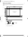 4
4
-
 5
5
-
 6
6
-
 7
7
-
 8
8
-
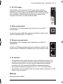 9
9
-
 10
10
-
 11
11
-
 12
12
-
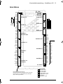 13
13
-
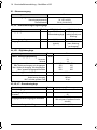 14
14
-
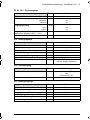 15
15
-
 16
16
-
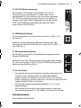 17
17
-
 18
18
-
 19
19
-
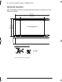 20
20
-
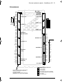 21
21
-
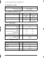 22
22
-
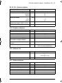 23
23
-
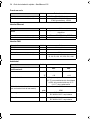 24
24
-
 25
25
-
 26
26
-
 27
27
-
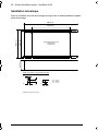 28
28
-
 29
29
-
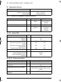 30
30
-
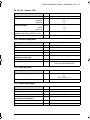 31
31
-
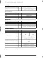 32
32
-
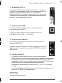 33
33
-
 34
34
-
 35
35
-
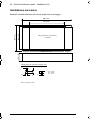 36
36
-
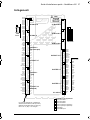 37
37
-
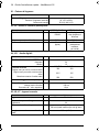 38
38
-
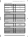 39
39
-
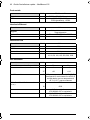 40
40
-
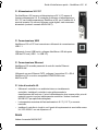 41
41
-
 42
42
-
 43
43
-
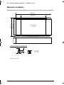 44
44
-
 45
45
-
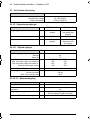 46
46
-
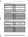 47
47
-
 48
48
-
 49
49
-
 50
50
-
 51
51
-
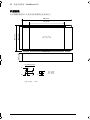 52
52
-
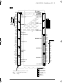 53
53
-
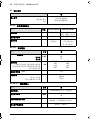 54
54
-
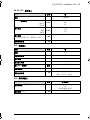 55
55
-
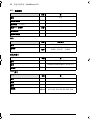 56
56
-
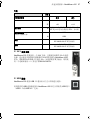 57
57
-
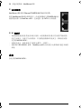 58
58
-
 59
59
-
 60
60


ABB NextMove e100 Quick Installation Manual
- Tipo
- Quick Installation Manual
en otros idiomas
- français: ABB NextMove e100
- italiano: ABB NextMove e100
- English: ABB NextMove e100
- Deutsch: ABB NextMove e100
- svenska: ABB NextMove e100
Artículos relacionados
-
ABB MicroFlex e150 Quick Installation Manual
-
ABB MotiFlex e180 Quick Installation Manual
-
-
-
-
-
-


