Ameriwood HD18484 Instrucciones de operación
- Tipo
- Instrucciones de operación
La página se está cargando...


B345683215WCOM1
3 /34
?? www.ameriwood.com ??
PARTS - PIEZAS
Parts List
DESCRIPTION
PART NUMBER
QTY
ITEM
LEFT PANEL356832150101A
RIGHT PANEL
356832150201B
TOP356832150301C
BOTTOM
356832150401D
CENTER MOLDING
356832150501E
UPPER SIDE MOLDING356852150802
H
LOWER RAIL
356852150902I
STRINGER
356830001301M
LEFT PANEL RAIL356832151401N
RIGHT PANEL RAIL
356832151501
O
UPPER FRONT MOLDING
356832151601P
FRONT LEG
356832151702
Q
REAR LEG
356832151802
R
BACK PANEL
K5683215001
S
Parts shown are the base cabinet of your model. Drawer is shown on next pages. Please note, some parts are labeled with a sticker and
some parts have a letter stamped on a raw edge.
.
Piezas mostradas son la base del gabinete de su modelo. Cajón se muestra en las siguientes páginas. Nota: algunas partes están
marcados con una etiqueta y algunas partes tienen una letra impresa en un borde.
This piece is paperboard construction. It is not made from
wood but is required for the assembly of your unit.
Esto pedazo son la construcción del cartón. Ello no son
hecho de madera, pero se requlere para la asamblea de su
unidad.
A
C
B
D
E
O
M
I
H
N
P
Q
Q
R
S
Spanish parts list on page 5.
Lista de piezas españolas en la página 5.
H

B345683215WCOM1
4 /34
?? www.ameriwood.com ??
PARTS - PIEZAS
Parts List
DESCRIPTION
PART NUMBER
QTY
ITEM
DRAWER FRONT
356832150601F
LEFT DRAWER SIDE
356833020701
G
RIGHT DRAWER SIDE
356833021001
J
DRAWER BACK
356833021101K
DRAWER BOTTOM
356833021201L
Parts shown are for the drawer of your model. Please note, some parts are labeled with a sticker and some parts have a letter stamped on a
raw edge.
Piezas mostradas son para el cajón de su modelo. Nota: algunas partes están marcados con una etiqueta y algunas partes tienen una letra
impresa en un borde.
K
G
J
L
F

B345683215WCOM1
5 /34
?? www.ameriwood.com ??
PARTS - PIEZAS
x
#A22570
cam lock
1
10
x
cam bolt
#A22510
2
10
x
16
connector
#A22920
3
x
416
#A22910
connector bolt
x
#A21660
wood dowel
5
6
x
6
14
#A12850
1" pan head
x
84
#A11600
1-1/4" flat head
x
#A17400
8-32 x 7/8" bolt
7
2
x
#A12120
7/16" pan head
9
12
x
#A11080
7/16" flat head
x
10
10
x
11
6
#A21110
nail
x
13
1
#A52480
knob
right cabinet memberleft cabinet member left drawer runner right drawer runner
x
#A56030
14d
14c14b
14 1
14a
x
12 2
#A54200
drawer bracket

B345683215WCOM1
6 /34
?? www.ameriwood.com ??
2
3
½ turn to fully
lock.
½ se vuelven a
totalmente
cerradura.
4
Tighten to fully seat. Do not over
tighten.
Apriétese a totalmente asiento. No
haga encima de apriétese.
Proper orientation of cam.
La orientación apropiada de leva.
1
This illustration shows how the CAM fastening system works.
Esta ilustración muestra el sistema de fijación de leva y como funciona.
Lock
Apretar
Serrer
T
i
t
u
s
T
i
t
u
s
T
i
t
u
s

1
B345683215WCOM1
7 /34
?? www.ameriwood.com ??
x
12
3
A
3
3
Finished Edge
Borde Acabado
B
Important: When using a power drill or power screwdriver for screwing, please be aware to slow down and stop when screw is
tight. Failure to do so may result in stripping the screw.
Importante: Cuando se utiliza un taladro eléctrico o corriente desarmador para atornillar, tenga en cuenta a despacio y se
detendrá cuando el tornillo está apretado. No hacerlo puede resultar en despojar el tornillo.
3
You will need to tap the connector (3) with a hammer
to fully insert. Be sure the connector is positioned as
shown before pushing into holes.
Quizá necesites golpear el conector (3) suavemente
con un martillo para insertar conpletamente. Esté
seguro que conectador está colocado como se
muestra antes de empujar en los agujeros.
Finished Edge
Borde Acabado
3
La página se está cargando...

3
B345683215WCOM1
9 /34
?? www.ameriwood.com ??
A
Q
R
Press the front and rear legs (Q&R) onto the left panel (A) so the connector bolts (4) engage the connectors (3). Turn the screw
in the center of the connector (3) clockwise to lock in place.
Small holes in rear surface.
Los agujeros pequeños en superficie posterior.
End View
Vista Final
Turn screw clockwise to lock in place.
Gire hacia la derecha el tornillo para bloquear en su lugar.
Finished Edge
Borde Acabado

4
B345683215WCOM1
10 /34
?? www.ameriwood.com ??
B
Q
R
End View
Vista Final
Press the front and rear legs (Q&R) onto the right panel (B) so the connector bolts (4) engage the connectors (3). Turn the screw
in the center of the connector (3) clockwise to lock in place.
Finished Edge
Borde Acabado
Small holes in rear surface.
Los agujeros pequeños en superficie posterior.
Turn screw clockwise to lock in place.
Gire hacia la derecha el tornillo para bloquear en su lugar.

5
B345683215WCOM1
11 /34
?? www.ameriwood.com ??
x
1
2
x
2
3
5
x
5
1
x
14 1
14a
x
x
3
10
A
R
Q
2
Proper orientation of CAM LOCK
Posición correcta de la cerradura de leva.
T
i
t
u
s
1
10
14a

6
B345683215WCOM1
12 /34
?? www.ameriwood.com ??
x
14 1
14b
x
x
3
10
x
5
1
x
2
3
x
12
Proper orientation of CAM LOCK
Posición correcta de la cerradura de leva.
T
i
t
u
s
5
1
B
R
Q
2
10
14b
La página se está cargando...
La página se está cargando...
La página se está cargando...
La página se está cargando...

11
B345683215WCOM1
17 /34
?? www.ameriwood.com ??
C
x
4
2
x
2
4
4
2

12
B345683215WCOM1
18 /34
?? www.ameriwood.com ??
x
14
x
5
2
5
Proper orientation of CAM LOCK
Posición correcta de la cerradura de leva.
T
i
t
u
s
5
D
1
1

13
B345683215WCOM1
19 /34
?? www.ameriwood.com ??
M
x
2
3
x
12
x
5
2
5
Proper orientation of CAM LOCK
Posición correcta de la cerradura de leva.
T
i
t
u
s
5
1
1
3
You will need to tap the connector (3) with a hammer to fully insert. Be
sure the connector is positioned as shown before pushing into holes.
Quizá necesites golpear el conector (3) suavemente con un martillo para
insertar conpletamente. Esté seguro que conectador está colocado como
se muestra antes de empujar en los agujeros.

14
B345683215WCOM1
20 /34
?? www.ameriwood.com ??
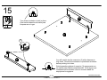
E
E
M
x
42
4
End View
Vista Final
Turn screw clockwise to lock in place.
Gire hacia la derecha el tornillo para bloquear en su lugar.

15
B345683215WCOM1
21 /34
?? www.ameriwood.com ??
P
P
C
3
x
2
3
Turn screw clockwise to lock in place.
Gire hacia la derecha el tornillo para
bloquear en su lugar.
You will need to tap the connector (3) with a hammer to
fully insert. Be sure the connector is positioned as shown
before pushing into holes.
Quizá necesites golpear el conector (3) suavemente con
un martillo para insertar conpletamente. Esté seguro que
conectador está colocado como se muestra antes de
empujar en los agujeros.
La página se está cargando...

17
B345683215WCOM1
23 /34
?? www.ameriwood.com ??
UNLOCK
LOCK
APRETAR
DESAPRETAR
C
P
A
B
La página se está cargando...

19
B345683215WCOM1
25 /34
?? www.ameriwood.com ??
x11 6
11
Assure that the unit is square.
Distance from corner to corner must be
equal as shown.
Asegura que el unidad es cuadrada.
Distancia de esquina a esquina debe ser
igual como se muestra por favor.
Flush the edge of the back panel with the
bottom edge of the bottom shelf. Align
squarely and nail straight through into back
edges. Now tighten the screws (9) from step
18.
Limpie el borde del panel posterior con el
borde inferior del estante inferior. Alinee
escuadra y clavarlas directamente a través
de los cantos posteriores. Ahora apriete los
tornillos (9) en el paso 18.
S
product collapse, and/or serious injury.
S’il-vous-plaît assurez-vous que les PANNEAUX
ARRIÈRES sont attachés solidement. Tous les clous
doivent être enfoncés perpendiculairement et solidement
dans les parties. Sinon le meuble peut devenir instable,
s’effondrer subitement et/ou causer des blessures graves.
tightened firmly. Failure to do so could cause instability,
All nails must be driven into the parts straight and
Please make sure that the Backs are attached securely.
AVERTISSEMENT
WARNING
La página se está cargando...

21
B345683215WCOM1
27 /34
?? www.ameriwood.com ??
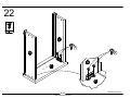
x
x
4
10
G
J
10
10
14c
14d
x
14 1
14d
14c
Finished Edge
Borde Acabado

22
B345683215WCOM1
28 /34
?? www.ameriwood.com ??
F
G
J
9
G
F
9
x
9
4

23
B345683215WCOM1
29 /34
?? www.ameriwood.com ??
L
G
J
F
L
J
Finished Surface
Superficie Acabado

24
B345683215WCOM1
30 /34
?? www.ameriwood.com ??
K
G
J
x
84
8
8

25
B345683215WCOM1
31 /34
?? www.ameriwood.com ??
13
F
x
7
2
x
13
1
7

26
B345683215WCOM1
32 /34
?? www.ameriwood.com ??
Notice, the drawer bracket holes are slotted. Drawer front can
be adjusted by loosening screws, making needed adjustments
and retightening screws.
Tenga en cuenta que los orificios de soporte del cajón se
ranuran. El frente del cajón se puede ajustar aflojando tornillos,
haciendo los ajustes necesarios y volver a apretar los tornillos.
corredera de mueble
cabinet member
rodillo
roller
drawer runner
deslizador de cajón
roller
rodillo

B345683215WCOM1
33 /34
?? www.ameriwood.com ??
MAXIMUM LOADS – CARGA MAXIMA - CHARGES MAXIMALES
This unit has been designed to
support the maximum loads shown.
Exceeding these load limits could
cause sagging, instability, product
collapse, and/or serious injury.
Esta unidad ha sido diseñada para
soportar la carga máxima anotada.
El exceder estos límites puede
causar inestabilidad, colapsarse y/o
causar serias lesiones.
40 lbs.
18.1 kg.
40 lbs.
18.1 kg.
15 lbs.
6.8 kg.

B345683215WCOM1
34 /34
?? www.ameriwood.com ??
Certificate of Conformity
1. This certificate applies to the Ameriwood Industries Inc. product identified by this instruction manual.
2. This certificate applies to compliance of this product with the CPSC Ban on Lead-Containing Paint (16 CFR 1303).
3. This product is distributed by: Ameriwood Industries Inc.
410 East First Street South
Wright City, MO 63390
636-745-3351
4. Site of Manufacture:
□ Tiffin OH
5. See front page of instruction manual for date of manufacture.
Transcripción de documentos
PARTS - PIEZAS Parts shown are the base cabinet of your model. Drawer is shown on next pages. Please note, some parts are labeled with a sticker and some parts have a letter stamped on a raw edge. Piezas mostradas son la base del gabinete de su modelo. Cajón se muestra en las siguientes páginas. Nota: algunas partes están marcados con una etiqueta y algunas partes tienen una letra impresa en un borde. . This piece is paperboard construction. It is not made from wood but is required for the assembly of your unit. Esto pedazo son la construcción del cartón. Ello no son hecho de madera, pero se requlere para la asamblea de su unidad. Spanish parts list on page 5. Lista de piezas españolas en la página 5. C H S P H R B M O E N A D Q ITEM A B C D E H I M N O P Q R S Parts List PART NUMBER QTY DESCRIPTION 1 35683215010 LEFT PANEL 1 35683215020 RIGHT PANEL 1 35683215030 TOP 1 35683215040 BOTTOM 1 35683215050 CENTER MOLDING 2 35685215080 UPPER SIDE MOLDING 2 35685215090 LOWER RAIL 1 35683000130 STRINGER 1 35683215140 LEFT PANEL RAIL 1 35683215150 RIGHT PANEL RAIL 1 35683215160 UPPER FRONT MOLDING 2 35683215170 FRONT LEG 2 35683215180 REAR LEG 1 K568321500 BACK PANEL I Q 3 /34 ?? www.ameriwood.com ?? B345683215WCOM1 PARTS - PIEZAS Parts shown are for the drawer of your model. Please note, some parts are labeled with a sticker and some parts have a letter stamped on a raw edge. Piezas mostradas son para el cajón de su modelo. Nota: algunas partes están marcados con una etiqueta y algunas partes tienen una letra impresa en un borde. ITEM F G J K L J K Parts List PART NUMBER QTY 1 35683215060 1 35683302070 1 35683302100 1 35683302110 1 35683302120 DESCRIPTION DRAWER FRONT LEFT DRAWER SIDE RIGHT DRAWER SIDE DRAWER BACK DRAWER BOTTOM L G F 4 /34 ?? www.ameriwood.com ?? B345683215WCOM1 PARTS - PIEZAS 1 x 10 2 x 10 #A22570 cam lock #A22510 cam bolt x 12 #A12120 7/16" pan head 10 9 14a #A22920 connector x 10 11 x #A11080 7/16" flat head right cabinet member 14 14c left drawer runner #A56030 x 16 4 5 #A22910 connector bolt x6 #A21110 nail 14b left cabinet member x 16 3 6 #A21660 wood dowel x2 12 x6 #A12850 1" pan head 7 x2 #A17400 8-32 x 7/8" bolt 8 x4 #A11600 1-1/4" flat head x 1 13 #A54200 drawer bracket x 14 #A52480 knob 14d right drawer runner x 1 5 /34 ?? www.ameriwood.com ?? B345683215WCOM1 This illustration shows how the CAM fastening system works. Esta ilustración muestra el sistema de fijación de leva y como funciona. 1 2 Tighten to fully seat. Do not over tighten. Apriétese a totalmente asiento. No haga encima de apriétese. Proper orientation of cam. La orientación apropiada de leva. 3 4 us Tit ½ turn to fully lock. ½ se vuelven a totalmente cerradura. Tit us us Tit 6 /34 ?? www.ameriwood.com ?? Lock Apretar Serrer B345683215WCOM1 1 Important: When using a power drill or power screwdriver for screwing, please be aware to slow down and stop when screw is tight. Failure to do so may result in stripping the screw. Importante: Cuando se utiliza un taladro eléctrico o corriente desarmador para atornillar, tenga en cuenta a despacio y se detendrá cuando el tornillo está apretado. No hacerlo puede resultar en despojar el tornillo. 3 You will need to tap the connector (3) with a hammer to fully insert. Be sure the connector is positioned as shown before pushing into holes. Quizá necesites golpear el conector (3) suavemente con un martillo para insertar conpletamente. Esté seguro que conectador está colocado como se muestra antes de empujar en los agujeros. A Finished Edge Borde Acabado 3 B 3 3 x 12 7 /34 ?? www.ameriwood.com ?? Finished Edge Borde Acabado 3 B345683215WCOM1 3 Press the front and rear legs (Q&R) onto the left panel (A) so the connector bolts (4) engage the connectors (3). Turn the screw in the center of the connector (3) clockwise to lock in place. Small holes in rear surface. Los agujeros pequeños en superficie posterior. Finished Edge Borde Acabado R A Q End View Vista Final Turn screw clockwise to lock in place. Gire hacia la derecha el tornillo para bloquear en su lugar. 9 /34 ?? www.ameriwood.com ?? B345683215WCOM1 4 Press the front and rear legs (Q&R) onto the right panel (B) so the connector bolts (4) engage the connectors (3). Turn the screw in the center of the connector (3) clockwise to lock in place. Small holes in rear surface. Los agujeros pequeños en superficie posterior. Finished Edge Borde Acabado R B Q End View Vista Final Turn screw clockwise to lock in place. Gire hacia la derecha el tornillo para bloquear en su lugar. 10 /34 ?? www.ameriwood.com ?? B345683215WCOM1 5 10 R A x2 1 14a Q 2 2 1 5 x1 Titus 5 x3 14a 10 x3 x 14 Proper orientation of CAM LOCK Posición correcta de la cerradura de leva. x1 11 /34 ?? www.ameriwood.com ?? B345683215WCOM1 6 10 R B 1 x2 14b Q 2 2 1 x3 5 x1 Titus 5 14b 10 x3 x 14 Proper orientation of CAM LOCK Posición correcta de la cerradura de leva. x1 12 /34 ?? www.ameriwood.com ?? B345683215WCOM1 11 2 2 x4 C 4 x2 4 17 /34 ?? www.ameriwood.com ?? B345683215WCOM1 12 1 x4 1 5 D x2 1 5 Titus 5 Proper orientation of CAM LOCK Posición correcta de la cerradura de leva. 18 /34 ?? www.ameriwood.com ?? B345683215WCOM1 13 1 Titus Proper orientation of CAM LOCK Posición correcta de la cerradura de leva. 1 3 x2 1 5 M x2 3 5 5 x2 You will need to tap the connector (3) with a hammer to fully insert. Be sure the connector is positioned as shown before pushing into holes. Quizá necesites golpear el conector (3) suavemente con un martillo para insertar conpletamente. Esté seguro que conectador está colocado como se muestra antes de empujar en los agujeros. 19 /34 ?? www.ameriwood.com ?? B345683215WCOM1 14 4 Turn screw clockwise to lock in place. Gire hacia la derecha el tornillo para bloquear en su lugar. E E M 4 x2 End View Vista Final 20 /34 ?? www.ameriwood.com ?? B345683215WCOM1 15 3 P Turn screw clockwise to lock in place. Gire hacia la derecha el tornillo para bloquear en su lugar. x2 C 3 P You will need to tap the connector (3) with a hammer to fully insert. Be sure the connector is positioned as shown before pushing into holes. Quizá necesites golpear el conector (3) suavemente con un martillo para insertar conpletamente. Esté seguro que conectador está colocado como se muestra antes de empujar en los agujeros. 21 /34 ?? www.ameriwood.com ?? B345683215WCOM1 17 UNLOCK DESAPRETAR LOCK APRETAR P C A B 23 /34 ?? www.ameriwood.com ?? B345683215WCOM1 19 11 WARNING Please make sure that the Backs are attached securely. All nails must be driven into the parts straight and tightened firmly. Failure to do so could cause instability, product collapse, and/or serious injury. AVERTISSEMENT S’il-vous-plaît assurez-vous que les PANNEAUX ARRIÈRES sont attachés solidement. Tous les clous doivent être enfoncés perpendiculairement et solidement dans les parties. Sinon le meuble peut devenir instable, s’effondrer subitement et/ou causer des blessures graves. S 11 x6 Flush the edge of the back panel with the bottom edge of the bottom shelf. Align squarely and nail straight through into back edges. Now tighten the screws (9) from step 18. Assure that the unit is square. Distance from corner to corner must be equal as shown. Asegura que el unidad es cuadrada. Distancia de esquina a esquina debe ser igual como se muestra por favor. Limpie el borde del panel posterior con el borde inferior del estante inferior. Alinee escuadra y clavarlas directamente a través de los cantos posteriores. Ahora apriete los tornillos (9) en el paso 18. 25 /34 ?? www.ameriwood.com ?? B345683215WCOM1 21 Finished Edge Borde Acabado J G 10 14d 14c 10 14d 14c 10 x4 x 14 x1 27 /34 ?? www.ameriwood.com ?? B345683215WCOM1 22 9 x4 J 9 G 9 G F F 28 /34 ?? www.ameriwood.com ?? B345683215WCOM1 23 L J L Finished Surface Superficie Acabado J G F 29 /34 ?? www.ameriwood.com ?? B345683215WCOM1 24 8 K 8 J G 8 x4 30 /34 ?? www.ameriwood.com ?? B345683215WCOM1 25 7 x2 7 F 13 13 x 1 31 /34 ?? www.ameriwood.com ?? B345683215WCOM1 26 Notice, the drawer bracket holes are slotted. Drawer front can be adjusted by loosening screws, making needed adjustments and retightening screws. Tenga en cuenta que los orificios de soporte del cajón se ranuran. El frente del cajón se puede ajustar aflojando tornillos, haciendo los ajustes necesarios y volver a apretar los tornillos. cabinet member corredera de mueble roller rodillo 32 /34 ?? www.ameriwood.com ?? roller rodillo drawer runner deslizador de cajón B345683215WCOM1 MAXIMUM LOADS – CARGA MAXIMA - CHARGES MAXIMALES This unit has been designed to support the maximum loads shown. Exceeding these load limits could cause sagging, instability, product collapse, and/or serious injury. 40 lbs. 18.1 kg. Esta unidad ha sido diseñada para soportar la carga máxima anotada. El exceder estos límites puede causar inestabilidad, colapsarse y/o causar serias lesiones. 15 lbs. 6.8 kg. 40 lbs. 18.1 kg. 33 /34 ?? www.ameriwood.com ?? B345683215WCOM1 Certificate of Conformity 1. This certificate applies to the Ameriwood Industries Inc. product identified by this instruction manual. 2. This certificate applies to compliance of this product with the CPSC Ban on Lead-Containing Paint (16 CFR 1303). 3. This product is distributed by: Ameriwood Industries Inc. 410 East First Street South Wright City, MO 63390 636-745-3351 4. Site of Manufacture: □ Tiffin OH 5. See front page of instruction manual for date of manufacture. 34 /34 ?? www.ameriwood.com ?? B345683215WCOM1-
 1
1
-
 2
2
-
 3
3
-
 4
4
-
 5
5
-
 6
6
-
 7
7
-
 8
8
-
 9
9
-
 10
10
-
 11
11
-
 12
12
-
 13
13
-
 14
14
-
 15
15
-
 16
16
-
 17
17
-
 18
18
-
 19
19
-
 20
20
-
 21
21
-
 22
22
-
 23
23
-
 24
24
-
 25
25
-
 26
26
-
 27
27
-
 28
28
-
 29
29
-
 30
30
-
 31
31
-
 32
32
-
 33
33
-
 34
34


