Faber Stratus 36 SS Guía de instalación
- Categoría
- Campanas de cocina
- Tipo
- Guía de instalación
Este manual también es adecuado para

STRTIS48SSNB
STRTIS36SSNB
Installation Instructions
Use and Care Information
Instructions d'installation
Utilisez et d'entretien
Instrucciones de instalación
Información de uso y cuidado
STRATUS NB

2
READ AND SAVE THESE INSTRUCTIONS BEFORE YOU START
INSTALLING THIS RANGEHOOD
WARNING: - TO REDUCE THE RISK OF A RANGE TOP GREASE FIRE:
a) Never leave surface units unattended at high settings. Boilovers cause smoking and
greasy spillovers that may ignite. Heat oils slowly on low or medium setting.
b)AlwaysturnhoodONwhencookingathighheatorwhenambeingfood(i.e.Crepes
Suzette, Cherries Jubilee, Peppercorn Beef Flambé).
c) Clean ventilating fans frequently. Grease should not be allowed to accumulate on fan
orlter.
d) Use proper pan size. Always use cookware appropriate for the size of the surface element.
WARNING: - TO REDUCE THE RISK OF INJURY TO PERSONS IN THE EVENT OF A
RANGE TOP GREASE FIRE, OBSERVE THE FOLLOWING*:
a)SMOTHERFLAMESwithaclose-ttinglid,cookiesheet,ormetaltray,thenturnofftheburner.
BECAREFULTOPREVENTBURNS.IftheamesdonotgooutimmediatelyEVACUATE
AND CALL THE FIRE DEPARTMENT.
b) NEVER PICK UP A FLAMING PAN - You may be burned.
c) DO NOT USE WATER, including wet dishcloths or towels - a violent steam explosion will
result.
d) Use an extinguisher ONLY if:
1. You know you have a Class ABC extinguisher, and you already know how to operate it.
2. Thereissmallandcontainedintheareawhereitstarted.
3. Theredepartmentisbeingcalled.
4. Youcanghttherewithyourbacktoanexit.
* Based on "Kitchen Firesafety Tips" published by NFPA
WARNING - TO REDUCE THE RISK OF FIRE OR ELECTRIC SHOCK, do not use this
fan with any solid-state speed control device.
WARNING - TO REDUCE THE RISK OF FIRE, ELECTRICAL SHOCK, OR INJURY TO
PERSONS, OBSERVE THE FOLLOWING:
1. Use this unit only in the manner intended by the manufacturer. If you have any
questions, contact the manufacturer.
2. Before servicing or cleaning unit, switch power off at service panel and lock the
service disconnecting means to prevent power from being switched on acciden-
tally. When the service disconnecting means cannot be locked, securely fasten a
prominent warning device, such as a tag, to the service panel.
CAUTION: For General Ventilating Use Only. Do Not Use To Exhaust Hazardous or
Explosive Materials and Vapors.
WARNING - TO REDUCE THE RISK OF FIRE, ELECTRICAL SHOCK, OR INJURY TO
PERSONS, OBSERVE THE FOLLOWING:
1. InstallationWorkAndElectricalWiringMustBeDoneByQualiedPerson(s)InAccor-
dance With All Applicable Codes And Standards, Including Fire-Rated Construction.
2. Sufcientairisneededforpropercombustionandexhaustingofgasesthrough
theue(chimney)offuelburningequipmenttopreventbackdrafting.Followthe
heating equipment manufacturer's guideline and safety standards such as those
publishedbytheNationalFireProtectionAssociation(NFPA), and the American
SocietyforHeating,RefrigerationandAirConditioningEngineers(ASHRAE),and
the local code authorities.

3
3. When cutting or drilling into wall or ceiling, do not damage electrical wiring and
other hidden utilities.
4. Ducted fans must always be vented to the outdoors.
ALL WALL AND FLOOR OPENINGS WHERE THE RANGEHOOD IS INSTALLED MUST
BE SEALED.
This rangehood requires at least 35" of clearance between the bottom of the rangehood
and the cooking surface or countertop. This hood has been approved by UL at this distance
from the cooktop.
Consult the cooktop or range installation instructions given by the manufacturer before making
any cutouts. MOBILE HOME INSTALLATION The installation of this rangehood must conform
to the Manufactured Home Construction and Safety Standards, Title 24 CFR, Part 3280 (formerly
Federal Standard for Mobile Home Construction and Safety, Title 24, HUD, Part 280).
• Venting system MUST terminate outside the home.
• DO NOT terminate the ductwork in an attic or other enclosed space.
• DO NOT use 4" laundry-type wall caps.
• Flexible-type ductwork is not recommended.
• DO NOT obstruct the ow of combustion and ventilation air.
• Failure to follow venting requirements may result in a re.
WARNING
!
Cold Weather installations
An additional back draft damper should be installed to minimize backward cold air ow and a
nonmetallic thermal break should be installed to minimize conduction of outside temperatures as
part of the vent system. The damper should be on the cold air side of the thermal break. The break
should be as close as possible to where the vent system enters the heated portion of the house.
VENTING REQUIREMENTS
Determine which venting method is best for your application. Ductwork can extend either through the
wall or the roof.
The length of the ductwork and the number of elbows should be kept to a minimum to provide efcient
performance. The size of the ductwork should be uniform. Do not install two elbows together. Use
duct tape to seal all joints in the ductwork system. Use caulking to seal exterior walls and ceiling space
opening around the cap.
Flexible ductwork is not recommended. Flexible ductwork creates back pressure and air turbulence
that greatly reduces performance.
Make sure there is proper clearance within the walls and ceiling space for exhaust duct before making
cutouts. Do not cut a joist or stud unless absolutely necessary. If a joist or stud must be cut, then a
supporting frame must be constructed.
WARNING - To Reduce The Risk Of Fire, Use Only Metal Ductwork.
CAUTION-Toreduceriskofreandtoproperlyexhaustair,besuretoductairoutside–Do
not vent exhaust air into spaces within walls or ceilings or into attics, crawl spaces, or garages.

4
ELECTRICAL REQUIREMENTS
A 120 volt, 60 Hz AC-only electrical supply is required on a separate 15 amp fused circuit. A time-delay
fuse or circuit breaker is recommended. The fuse must be sized per local codes in accordance with
the electrical rating of this unit as specied on the serial/rating plate located inside the unit near the eld
wiring compartment.
ELECTRICAL INSTALLATION WITH WIRING BOX
THIS UNIT MUST BE CONNECTED WITH COPPER WIRE ONLY. Wire sizes must conform to the
requirements of the National Electrical Code, ANSI/NFPA 70 - latest edition, and all local codes and
ordinances. Wire size and connections must conform with the rating of the appliance. Copies of the
standard listed above may be obtained from:
National Fire Protection Association
Batterymarch Park
Quincy, Massachusetts 02269
This appliance should be connected directly to the fused disconnect (or circuit breaker) through
exible, armored or nonmetallic sheathed copper cable. Allow some slack in the cable so the
appliance can be moved if servicing is ever necessary. A UL Listed, 1/2" conduit connector must
be provided at each end of the power supply cable (at the appliance and at the junction box).
When making the electrical connection, cut a 1 1/4" hole. A hole cut through wood must be
sanded until smooth. A hole through metal must have a grommet.
• Electrical ground is required on this rangehood.
• If cold water pipe is interrupted by plastic, nonmetallic gaskets or other materials, DO
NOT use for grounding.
• DO NOT ground to a gas pipe.
• DO NOT have a fuse in the neutral or grounding circuit. A fuse in the neutral or
grounding circuit could result in electrical shock.
• Check with a qualied electrician if you are in doubt as to whether the rangehood is
properly grounded.
• Failure to follow electrical requirements may result in a re.
WARNING
!
StateofCaliforniaProposition65Warning(USonly)
WARNING
This product contains chemicals known to the State of California to cause cancer and birth
defects or other reproductive harm.
For more information go to www.P65Warnings.ca.gov

5
RANGEHOOD DIMENSIONS
Max. 72"Min. 35"
Recommended 60" mounting height above the
cooking surface for best performance, but can be
mounted up to 72" maximum away the cooking
surface.

6
MAIN PARTS
Components
Ref. Qty. Product Components
1 1 Hood Body, complete with: Con-
trols, Lights, Filters.
2 2 UpperxingHoodBrackets
3 2 BottomxingHoodBrackets
10 1 Damperø57/8"
20 1 Flange10"(NotIncluded)
30 1 Remote Control
Ref. Qty. Installation Components
4 4 Screws1/4"x9/16"
5 8 Screws1/8"x3/8"
6 4 Screws1/8"x1/4"
7 1 Screws3/16"x1/4"(onlyfor
STRTIS48SSNB)
Qty. Documentation
1 InstructionManual
Available Accessories
Activated Charcoal Filter Accessory - sku#; FILTER 1
Activated Charcoal Filter Accessory - sku#; FILTER 1LL
Internal 600 PRO Blower sku#; IB600 kit
Internal 400 Blower sku#; IB400 kit
Internal 300 Blower sku#; IB300
Remote Blower 900 sku#; RB900
Remote Blower 1200 sku#; RB1200
10" Flange for Remote Blower sku# FLANGE10
Parts needed
- 6" Round Metal ductwork
“CAUTION - To Reduce The Risk Of Fire And Electric Shock, Install This Rangehood Only
With Remote Blower Models RB900 or RB1200 Manufactured by Faber Or Integral Blow-
ers Manufactured by Faber, Model(s) IB600 kit, IB400 kit, IB300 or generic remote blower
rated max 2,7A suitable for use with solid state speed control.
10
1
2
3
4
5
30
20
6
7

7
INSTALLATION
COMBINATIONS HOODS AND MOTOR KITS
RB900 and RB1200
(remote blower)
IB600 kit, IB400 kit,
IB300
(internal blower)
Version 07/11 - Page 6
INSTALLATION
COMBINATIONS HOOD AND MOTOR KITS
CHOOSE A BLOWER FOR YOUR HOOD
After choosing the hood width and depth for your cooking
needs, next choose the type of blower appropriate for
your cooking.
NOTE: no other blower is
compatible with this hood, except for the
kits below.
# IB300 - Internal Blower Kit 300 cfm
# IB600 - Internal Blower Kit 600 cfm
# IB1200 - Internal Blower Kit 1200 cfm
# RB900 - Remote Blower Kit 900 cfm
# RB1200 - Remote Blower Kit 1200 cfm
# INLBKIT - In Line Blower Kit
(supply own in-line blower)
OPTIONAL ACCESSORIES AVAILABLE
• *Charcoal Filter
* it is highly recommended that professional style cooking always be
vented to the outside; for recirculating installations only, some ductwork is
required to exhaust the unit out of the cabinet. Replace as needed with the
same model
part # FILTER1
NOTE: The charcoal filter kit for use with the 300 / 600
cfm internal blower kit ONLY
CAUTION - To reduce risk of fire and electric shock, install this rangehood only with: Remote blower manufacturer by Faber
models RB900 and RB1200 or Integral blower manufactured by Faber models IB300 or IB600 or IB1200 or with INLBKIT and
generic in-line blower rated max 4.2 A suitable for use with solid state variable speed control
INLBKIT
1B
1D
2B
E
(Not needed
with Stratus)
(Not needed
with Stratus)
(Not needed
with Stratus)
(Not used with 10"
External Blowers)

8
Choose your ducting method
Non Ducted - Recirculation OptionDucted Venting Options Installation
Activated Charcoal Filter Accessory
FILTER1 required (Purchased separately).
Register cover for air duct exit is shown for
design - not included.
When used in recirculation mode,
To Reduce the Risk of Fire and
Shock use only conversion kit Model
FILTER1
6 "
6 "

9
Blower Cable Wiring Box & Power Supply Cable Wiring Box
WIRING BOX 1 for
connecting the Home
power supply cable
with the Hood.
WIRING BOX 2
for connecting the
External Blower with
the Hood.

10
1
Put a thick, protective covering over cooktop
to protect from damage or dirt.
Determine and clearly mark with a pencil on the
ceiling where the rangehood will be installed.
Determine and make necessary cuts for the
ductwork. The duct opening is shown on the
mounting template.
Install ductwork before mounting the hood.
Determine the proper location for the Power
Supply Cable as indicated on the template.
Use a 1 1/4" Drill Bit to make this hole. Run
the Power Supply Cable. Use caulking to seal
around the hole.
A knockout for threading through the Power
Supply from the ceiling is located on the top
of the frame. Do not connect the Power Cable
to the Wiring Box or power up the hood at this
time. Run enough power cable from the ceiling
to reach the wiring box on the hood.
Do not make any cutouts until you have decided whether this installation will be ducted or
non-duct and then plan accordingly.
DUE TO THE SIZE AND
WEIGHT OF THIS RANGE-
HOOD, THE SUPPORT MUST
BE FIRMLY ATTACHED TO
THE CEILING. For plaster or
sheet rock ceiling, the support
must be attached to the joists.
If this is not possible, a support
structure must be built behind
the plaster or sheet rock. The
manufacturer assumes no re-
sponsibility for injury or damage
caused by improper installa-
tions.
WARNING
!
Ceiling Hood Install Preparation

11
2
3
Unfastenthe4screwstodismounttheBlowerBoxfromthehoodbodyandtosavescrews.
TheBlowerBoxisnotusedforRemoteBlowerinstallationandcanbediscardedorsavedforfutureuse
ifconvertedtoInternalBlower.
Fixthe10"
ange(#FLANGE10
-purchasedseparately)with
the4screwsprovidedinthe
hardwarebagasshown.
External Blower Installation 10"
lf you use the remote blower kit, RB900 or RB1200, please throw away the ange (1B)
given with the remote blower kit,shown on page 7.

12
4
ConnecttheHoodbodyair
outletwiththeRemoteBlower
airoutlet.
5
FromInsidetheHood,removethe
Cover from the wiring box 2 by
removingtwoscrews.
BreakthecorrectholeintheWiring
Boxforpassingthecablesfromthe
remoteblower.
FromInsidetheHoodconnectthe
CabletotheWiringBOXasshown
intheimagetotheright.
ConnectthecablefromtheRemoteBlowerwiththe
twowiresinsidetheWiringBoxbytwist-on type wire
connectorandmatchingthecolor
Replacetheeldwiringcompartmentcover.
ChecktheWiringDiagram.
A
E
D
C
B

13
1
IfnecessarytheBlowerBoxisdismounted
fromthebodyasshownintheimageto
the right.
TheBlowerBoxcanbepositionedinfourdifferentventingdirectionsasshown.
Choosethecorrectpositionforyourinstallation.
Connecttheductingfromthe
Remote Blower to the Blower
Box.Useclampstosecure
(purchasedseparately).
2
External Blower Installation 6"
lf you use the remote blower kit, RB900 or RB1200, please throw away the ange (1B) given with the
remote blower kit1shown on page 7. With this installation there may be a performance degradation
due to the transition from 6" to 10" of the Remote Blowers.

14
3
Frominsidethehood,removethe
cover from the Wiring Box 2 by
removingthetwoscrews.
Breakthehole intheWiringBox
for passing the cables from the
remoteblower.
FromInsidetheHoodconnectthe
cabletotheWiringBOX2.
ConnectthecablefromtheRemoteBlowerwiththetwo
wireinsidetheWiringBoxbytwist-on type wire connec-
torandmatchingthecolor.
Replacetheeldwiringcompartmentcover.
ChecktheWiringDiagram.
A
E
D
C
B

15
2
4
Unfastenthe4screwstodismountthe
Boxfortheblower.
Theblowercanbepositionedinfourdifferentventingdirectionsasshown.
3
PositionInternalBlowerasshownintothe
removedBlowerBox.SecuretheInternal
BlowerintheBlowerBoxwiththetwoscrews
providedwiththeInternalBlower.
Internal Blower Installation
lf you use the internal blower kit, IB600 kit or IB400 kit or IB300, please throw away the
damper (A), the ange (2B) and the cable (E), given with the internal blower kit, shown on
page 7.

16
5
FixtheBoxwiththeBlowerwiththesame4screws
removedpreviously.
AftertheBlowerismountedinthe
hoodplugtheConnectorintothe
Blower
6
ConnectthecabletotheMotor.

17
Fixing the Security Cable
Fix the Free part of Security Cable at the panel with a Screw 7 supplied.
A
B
C

18
Assemble the Brackets at the proper measure
$
PP
; $PP
;
%[
5
X = A - 5 1/16"
5 1/16"
7
Asshown,youhave
toaccommodate
fortheheightofthe
hoodbodyintoyour
spaceoverhead.After
determiningbracket
heightusethe#5
ScrewsfromComponent
Page6toassemble
brackets.
15
3/4
”
33
1/16
” - 44 7/8”
Seebelowforadetailedimageondrilling
theholesontothefasteningsurface(inside
ceilingorsoft)thatwillthenbeusedto
mountthebracketxtures.Thefasteners
usedmustbecompatiblewiththe5/16"hole
andarepurchasedseparately.
Ceiling Bracket Installation
Hood
36" 153/4" 33 1/16"
48" 153/4" 44 7/8"
8.a
Min. 7 5/16"
Max. 12 13/16"
HOOD INSTALLATION BEFORE THE SOFFIT IS COMPLETED

19
´
[
[
Usethebracketstomarkyourholesforlocationoftheceilingfasteners(purchasedseparately).
Usewallplugsorothersecuringhardwareinconjunctionwiththeceilingfasteners(purchased
separately).
9.a
´
[
[
10.a
C (M6x15)
Use the #4 Screws from the
ComponentlistonPage6toattach
thehoodbodytothehoodceiling
brackets.
Accessisneededinthespaceabove.

20
CeilingCutoutforSoft
8.b
Seeimagewithdimensions
forceilingcutout.
Ø 5/16”
x4
x4
475
878
15
3/4
”
23
5/8
” - 31
5/8
”
18
11/16
” - 26
9/16
”
23
5/8” - 31
5/8
”
X
Y
9.b
Seebelowforadetailedimageondrilling
theholesontothefasteningsurface(inside
ceilingorsoft)thatwillthenbeusedto
mountthebracketxtures.Thefasteners
usedmustbecompatiblewiththe5/16"hole
andarepurchasedseparately.
Hood
36" 153/4" 235/8"
48" 153/4" 31 5/8"
CeilingBracketInstallationforSoft
Hood X Y
36" 18 11/16" 34 9/16"
48" 269/16" 463/8"
´
´
´
HOOD INSTALLATION AFTER THE SOFFIT IS COMPLETED

21
Usethebracketsto
markyourholesfor
locationoftheceiling
fasteners(purchased
separately).
Usewallplugsorother
securinghardwareincon-
junctionwiththeceiling
fasteners(purchased
separately).
Usethe#4ScrewsfromtheComponent
listonPage6toattachthehoodceiling
bracketsfromthebottom.
10.b
1 2
C (M6x15)
3
Ø 8 mm
A (5x70)
x4
x4
475
878
400
600 -
803
475 - 675
878 - 1178
5/16"

22
Installthehoodwiththecontrolpanelontherightasshownabove.
$[
PP
[
[

23
Choose your ducting method
Ducted Venting Installation
11
Install Damper that is included with the
Hood before connecting to the ductwork.
H
I
Connect the hood to the pipe for air out-
let. Use duct tape to seal the joint.
$[
PP
[
[
0LQFP
Non Ducted -
Recirculation Option
´
See the image above and below as two
duct venting options for non-ducted recircu-
lation back into the room.
keep the return air duct at least 40" away
from the side of the Stratus
40"

24
Installation of wiring
box connection 1
Removethecoverfromthe
eldwiringcompartment.
DONOTturnonthepoweruntil
installationiscomplete!
ConnectthePowerSupply
Cabletotherangehood.
ConnecttheGreen(Greenand
Yellow)groundwireunderthe
Greengroundingscrew.Attach
theWhiteleadofthepower
supplytotheWhiteleadofthe
rangehoodwithatwist-ontype
wire connector.
AttachtheBlackleadofthe
powersupplytotheBlacklead
oftherangehoodwithatwist-
on type wire connector.
Replacetheeldwiringcompart-
mentcoverandthegreaselters.
ChecktheWiringDiagram.
A. Home power supply cable
B. Black wires
C. UL listed wire connectors
D. White wires
E. Green (or bare) ground wire from home power supply to be connected to green ground
screw
F. Range hood power supply cable
14
12 13
Opentheltercoverpanel.Theltercoverpanel
isheldbyamagnetcatch,pulldownwithenough
forcetoreleaseasshownabove.
Removethegreaseltersoneatatime,pushing
themtowardsthebackoftheunit,andatthesame
timepullingdownwardandsetaside.
E
A
F
D
C
B

25
15
For Non-Ducted Recirculation Option
Attach each charcoal lter to the black
grid on each side of the blower. Press the
charcoal lter tightly to the black grid on the
blower side and rotate the lter clockwise
(towards the front of the insert hood) until it
locks into place (A). Turn counterclockwise
(towards the back of the insert hood) to
remove (B).
Required Activated Charcoal Filter
Accessory - sku # - FILTER1
(purchased separately)
1716
Closetheltercoverpanel.Replacethegreaselters.
A
B

26
USE AND CARE INFORMATION
For Best Results
Start the rangehood several minutes before cooking to develop proper airow. Allow the rangehood to
operate for several minutes after cooking is complete to clear all smoke and odors from the kitchen.
Button Function Led
L Turns the lights on/off at maximum strength. -
Press and hold the button for approximately 2 seconds to turn the Dimmer Lights
On/Off.
-
T1 Turns the motor on/off at speed one. ON
Delay function:
Press and hold the button for approx. 3 seconds to Activate/Deactivate the Delay
function (automatic switching off of the Motor, the Fans and the Lighting with a 30
min. delay). Cannot be enabled when Intensive is on.
T2 Turns the Motor on at speed two. ON
Activated Charcoal Filter Alarm -
Press and hold the button for approximately 5 seconds, with all the hood turned off
(Motor and Lights), to turn the alarm on. The relevant LED ashes twice to conrm.
To turn the alarm off, press the button again and hold for at least 5 seconds. The
relevant LED ashes once.
T3 Turns the Motor on at speed three. ON
Press and hold the button for approximately 3 seconds, with all the hood turned off
(Motor and Lights), to perform a reset. The LED S1 ashes three times.
T4 Turns the Motor on at INTENSIVE Speed.
This speed is timed to run for 6 minutes. At the end of this time, the system returns
automatically to the speed that was set before. If it is activated with the motor turned
off, the hood will switch to OFF at the end of the time.
ON
Remote Control Activation
Press and hold for 5 seconds to enable the remote control, indicated by the LED
ashing twice.
Press and hold for 5 seconds to disable the remote control, indicated by the LED
ashing just once.
S1 Signals the Metal Grease Filter saturation alarm, indicating that it is necessary to
wash the lters. The alarm is triggered after the Hood has been in operation for 100
working hours. (Refer to Page 18 for Cleaning Filters and Reset of Filter Alarm)
ON
When this is activated, it signals the Activated Charcoal Filter saturation alarm,
indicating that the lter must be changed; the Metal Grease Filters must also be
washed. The Activated Charcoal Filter saturation alarm comes into operation after
the Hood has been working for 200 hours. (Refer to Page 18 for Cleaning Filters
and Reset of Filter Alarm)
Flashing.

27
REMOTE CONTROL
The appliance can be controlled using a remote
control powered by a 1.5 V carbon-zinc alkaline
batteries of the standard LR03-AAA type (not
included).
• Do not place the remote control near to heat
sources.
• Used batteries must be disposed of in the
proper manner.
EN
1
19
REMOTE CONTROL
The appliance can be controlled using a remote control
powered by a 1.5 V carbon-zinc alkaline batteries of the
standard LR03-AAA type (not included).
• Do not place the remote control near to heat sources.
• Used batteries must be disposed of in the proper
manner.
Remote control panel
Motor Motor On / Off.
Decreases the working speed each time it is pressed.
Increases the working speed each time it is pressed.
Intensive Activates the Intensive function
Delay Activates / Deactivates the Delay function
Light Lights On / Off
Press for 2 seconds to modify the intensity of the Light.
Motor Motor On / Off
EN
1
19
REMOTE CONTROL
The appliance can be controlled using a remote control
powered by a 1.5 V carbon-zinc alkaline batteries of the
standard LR03-AAA type (not included).
• Do not place the remote control near to heat sources.
• Used batteries must be disposed of in the proper
manner.
Remote control panel
Motor Motor On / Off.
Decreases the working speed each time it is pressed.
Increases the working speed each time it is pressed.
Intensive Activates the Intensive function
Delay Activates / Deactivates the Delay function
Light Lights On / Off
Press for 2 seconds to modify the intensity of the Light.
Decreases the working speed each time it is pressed
EN
1
19
REMOTE CONTROL
The appliance can be controlled using a remote control
powered by a 1.5 V carbon-zinc alkaline batteries of the
standard LR03-AAA type (not included).
• Do not place the remote control near to heat sources.
• Used batteries must be disposed of in the proper
manner.
Remote control panel
Motor Motor On / Off.
Decreases the working speed each time it is pressed.
Increases the working speed each time it is pressed.
Intensive Activates the Intensive function
Delay Activates / Deactivates the Delay function
Light Lights On / Off
Press for 2 seconds to modify the intensity of the Light.
Increases the working speed each time it is pressed
EN
1
19
REMOTE CONTROL
The appliance can be controlled using a remote control
powered by a 1.5 V carbon-zinc alkaline batteries of the
standard LR03-AAA type (not included).
• Do not place the remote control near to heat sources.
• Used batteries must be disposed of in the proper
manner.
Remote control panel
Motor Motor On / Off.
Decreases the working speed each time it is pressed.
Increases the working speed each time it is pressed.
Intensive Activates the Intensive function
Delay Activates / Deactivates the Delay function
Light Lights On / Off
Press for 2 seconds to modify the intensity of the Light.
Intensive Activates/Deactivates the Intensive function
EN
1
19
REMOTE CONTROL
The appliance can be controlled using a remote control
powered by a 1.5 V carbon-zinc alkaline batteries of the
standard LR03-AAA type (not included).
• Do not place the remote control near to heat sources.
• Used batteries must be disposed of in the proper
manner.
Remote control panel
Motor Motor On / Off.
Decreases the working speed each time it is pressed.
Increases the working speed each time it is pressed.
Intensive Activates the Intensive function
Delay Activates / Deactivates the Delay function
Light Lights On / Off
Press for 2 seconds to modify the intensity of the Light.
Delay Activates/Deactivates the Delay function
EN
1
19
REMOTE CONTROL
The appliance can be controlled using a remote control
powered by a 1.5 V carbon-zinc alkaline batteries of the
standard LR03-AAA type (not included).
• Do not place the remote control near to heat sources.
• Used batteries must be disposed of in the proper
manner.
Remote control panel
Motor Motor On / Off.
Decreases the working speed each time it is pressed.
Increases the working speed each time it is pressed.
Intensive Activates the Intensive function
Delay Activates / Deactivates the Delay function
Light Lights On / Off
Press for 2 seconds to modify the intensity of the Light.
Light
Light On / Of
Press for 2 seconds to Activate Dimmer.

28
Cleaningmetalgreaselters
Thesecanbewashed inthedishwasher,andneedtobe
cleanedwhenevertheS1Ledcomesonoratleastonceevery2
monthsofuse,ormorefrequentlyifuseisparticularlyintensive.
Resetting the Grease Filter Alarm
• TurntheLightsandtheHoodoff.
• PressT3andholdforatleast3seconds,untilLEDashes
threetimesinconrmation.
Cleaning the Filters
• OpenthePanel.
• RemovetheFiltersoneatatime,pushingthemtowards
thebackoftheunitandatthesametimepullingdownward.
• WashtheFilterswithoutbendingthem,andleavethemto
drycompletelybeforereplacing.(Ifthesurfaceofthelter
changescolorastimegoesby,thiswillhaveabsolutelyno
effectontheefciencyofthelteritself.)
• Replacethegreaselters,takingcaretoensurethatthe
handlefacesforward
• ClosethePanel.
• 4Filters-48"model,3Filters-36"model.
Replacing Activated Charcoal Filter
Theycannotbewashedorregenerated,andmustbechanged
whenledS1startstoash,oratleastonceevery6months.
TheAlarmsignal,ifithasbeenactivated,onlyappearswhen
theHoodBloweristurnedon.
Resetting the alarm signal
• TurntheLightsandtheHoodBloweroff.
• PressT3andholdforatleast3seconds,untilLEDashes
threetimesinconrmation.
Cleaning the Filters
• OpenthePanel.
• RemovetheMetalGreaseFilter.
• Remove the saturated Activated Charcoal Filters, as
indicated(A).
• FitthenewFilters,asindicated(B).
• ReplacetheMetalgreaselters.
• ClosethePanel.
Lighting unit
• LEDlightsmustbereplacedbyFaberfactoryauthorized
service.
A
B

29
Wiring Diagram
991.0515.826 H90-349
D004054_00
991.0515.826 H90-349
D004054_00

30
January 4, 2016
FABER CONSUMER WARRANTY & SERVICE
All Faber products are warranted against any defect in materials or workmanship for the original purchaser
for a period of 1 year from the date of original purchase (requires proof of purchase). This warranty covers
labor and replacement parts. Faber, at its option, may repair or replace the product or components
necessary to restore the product to good working condition. To obtain warranty service, contact the dealer
from whom you purchased the range hood, or the local Faber distributor. If you cannot identify a local Faber
distributor, contact us at (508) 358-5353 for the name of a distributor in your area.
The following is not covered by Faber's warranty:
1. Service calls to correct the installation of your range hood, to instruct you how to use your range hood, to
replace or repair house fuses or to correct house wiring or plumbing.
2. Service calls to repair or replace range hood light bulbs, fuses or filters. Those consumable parts are
excluded from warranty coverage.
3. Repairs when your range hood is used for other than normal, single-family household use.
4. Damage resulting from accident, alteration, misuse, abuse, fire, flood, acts of God, improper installation,
installation not in accordance with electrical or plumbing codes or Faber documentation, or use of products
not approved by Faber.
5. Replacement parts or repair labor costs for units operated outside the United States or Canada, including
any non-UL or C-UL approved Faber range hoods.
6. Repairs to the hood resulting from unauthorized modifications made to the range hood.
7. Expenses for travel and transportation for product service in remote locations and pickup and delivery
charges. Faber range hoods should be serviced in the home.
THIS WARRANTY DOES NOT ALLOW RECOVERY OF INCIDENTAL OR CONSEQUENTIAL DAMAGES, INCLUDING, WITHOUT
LIMITATION, DIRECT, INDIRECT, INCIDENTAL, SPECIAL OR CONSEQUENTIAL DAMAGES, PERSONAL INJURY/WRONGFUL
DEATH OR LOST PROFITS FABER WARRANTY IS LIMITED TO THE ABOVE CONDITIONS AND TO THE WARRANTY PERIOD
SPECIFIED HEREIN AND IS EXCLUSIVE. EXCEPT AS EXPRESSLY SPECIFIED IN THIS AGREEMENT, FABER DISCLAIMS ALL
EXPRESS OR IMPLIED CONDITIONS, REPRESENTATIONS, AND WARRANTIES INCLUDING, WITHOUT LIMITATION, ANY
IMPLIED WARRANTIES OF MERCHANTABILITY OR FITNESS FOR A PARTICULAR PURPOSE
.
This warranty gives you specific legal rights that may vary from state to state.
Model#: ______________________________ Serial #: _____________________________

31
VEUILLEZ LIRE ET CONSERVER LA PRÉSENTE NOTICE AVANT DE
COMMENCER L'INSTALLATION DE LA HOTTE DE CUISINE
AVERTISSEMENT:-POURRÉDUIRELE RISQUED'UNFEUDE GRAISSESURLATABLEDE
CUISSON:
a) Ne laissez jamais sans surveillance les éléments de la surface de cuisson à température élevée.
Les bouillonnements excessifs peuvent provoquer de la fumée et les débordements de graisse
peuvents'enammer.L'huiledoitêtrechaufféelentement,àunetempératurebasseoumoyenne.
b) Assurez-vous de toujours mettre en marche la hotte lorsque vous cuisinez à température élevée
oupréparezunmetsambé(p.ex.crêpesSuzette,cerisesjubilé,bœufambé).
c) Nettoyez régulièrement les ventilateurs d'aspiration. Assurez-vous de ne pas laisser de la graisse
s'accumulersurleventilateurouleltre.
d)Utiliseztoujoursdespoêlesetcasserolesdelatailleappropriée.Utiliseztoujoursdesustensiles
de cuisine de la taille adaptée à celle de l'élément chauffant.
AVERTISSEMENT:-POURPRÉVENIRLESBLESSURESENCASDEFEUDEGRAISSESURLA
TABLEDECUISSON,SUIVEZLESRECOMMANDATIONSSUIVANTES*:
a) ÉTOUFFEZ LES FLAMMES à l'aide d'un couvercle hermétique, d'une plaque à biscuits ou d'un
plateau métallique, puis éteignez le brûleur. FAITES ATTENTION AUX BRÛLURES. Si le feu ne
s'éteint pas immédiatement, QUITTEZ LES LIEUX ET APPELEZ LES POMPIERS.
b) NE PRENEZ JAMAIS UNE CASSEROLE EN FLAMME - Vous pourriez vous brûler.
c) N'UTILISEZ JAMAIS DE L'EAU, ni un linge à vaisselle ou un torchon mouillé, pour éteindre le feu.
Cela pourrait provoquer une violente explosion de vapeur.
d)UtilisezunextincteurUNIQUEMENTsi:
1. Vousêtescertainqu'ils'agitd'unextincteurdeclasseABCetquevousconnaissezbienson
mode d'emploi.
2. Le feu est de faible intensité et se limite à l'endroit où il a démarré.
3. Les pompiers ont déjà été appelés.
4. Unevoiedesortiesetrouvederrièrevouspendantquevouséteignezlesammes.
* D'après le guide «Kitchen Firesafety Tips» publié par la NFPA aux États-Unis
AVERTISSEMENT - POUR RÉDUIRE LE RISQUE D'INCENDIE OU DE CHOC ÉLECTRIQUE, n'utilisez
jamais ce ventilateur en association avec un dispositif de réglage de vitesse à semi-conducteurs.
AVERTISSEMENT - POUR RÉDUIRE LES RISQUES D'INCENDIE, DE CHOC ÉLECTRIQUE OU DE
BLESSURECORPORELLE,RESPECTEZLESINSTRUCTIONSSUIVANTES:
1. Utilisez cet appareil uniquement de la façon prévue par le fabricant. Pour toute question, com-
muniquez avec le fabricant.
2. Avant de procéder à l'entretien ou au nettoyage de l'appareil, coupez l'alimentation au niveau
du panneau électrique et verrouillez-le pour vous assurer que l'électricité n'est pas rétablie
accidentellement. S'il n'est pas possible de verrouiller le dispositif d'interruption de l'alimen-
tation,afchezdefaçonfermeetbienvisibleunavisdedanger,parexempleàl'aided'une
étiquette sur le panneau.
ATTENTION:Destinéàunusagedeventilationgénéraleuniquement.N'utilisezpascedispositif
pour l'aspiration de vapeurs ou de matériaux dangereux ou explosifs.
AVERTISSEMENT - POUR RÉDUIRE LES RISQUES D'INCENDIE, DE CHOC ÉLECTRIQUE OU DE
BLESSURECORPORELLE,RESPECTEZLESINSTRUCTIONSSUIVANTES:
1. L'installationetlebranchementélectriquedoiventêtreréalisésparuntechnicienqualiéet
conformément à tous les codes et normes en vigueur, incluant ceux concernant la construction
à l'épreuve du feu.
2. Andegarantirunecombustionetuneévacuationadéquatesdesgazparlesconduitesde
la cheminée des appareils à combustion, une bonne aération est nécessaire pour éviter le
refoulement. Respectez les lignes directrices fournies par le fabricant du matériel chauffant,
ainsi que les normes de sécurité comme celles publiées par la National Fire Protection Asso-
ciation(NFPA)etlaAmericanSocietyforHeating,RefrigerationandAirConditioningEngineers
(ASHRAE)auxÉtats-Unis,ainsiquelescodesenvigueurdansvotrerégion.

32
3. Lorsque vous faites une ouverture ou percez dans un mur ou le plafond, veillez à ne pas
endommagerleslsélectriquesoud'autresdispositifscachés.
4. Lesventilateurscanalisésdoiventtoujoursêtreraccordésàl'extérieur.
TOUTE OUVERTURE DANS LE MUR OU LE PLANCHER À PROXIMITÉ DE LA
HOTTE DOIT ÊTRE SCELLÉE.
Un espace libre d'au moins 35" est requis entre le bas de la hotte et la surface de
cuisson ou le comptoir. Cette hotte a été homologuée par l'UL à cette distance de la
surface de cuisson.
Consultez la notice d'installation de la surface de cuisson ou de la cuisinière fournie par
le fabricant avant de pratiquer des ouvertures. INSTALLATION DANS UNE MAISON
MOBILE L'installation de cette hotte doit être conforme à la Partie3280 de la norme
Manufactured Home Construction and Safety Standards, Title24 CFR (précédemment
la partie 280 de la norme Federal Standard for Mobile Home Construction and Safety,
Title24, HUD).
• Le système de ventilation DOIT déboucher à l'extérieur.
• NE FAITES PAS déboucher les conduits dans un grenier ou un autre endroit fermé.
• N'UTILISEZ PAS un clapet de sécheuse mural de 4".
• Il n'est pas recommandé d'utiliser des conduits exibles.
• N'ENTRAVEZ PAS le ux de l'air de combustion et de ventilation.
• Le non-respect des exigences en matière de ventilation pourrait entraîner un incendie.
AVERTISSEMENT
!
Installation dans les climats froids
Le système de ventilation doit prévoir un registre antirefoulement supplémentaire pour
réduire le ux d'air froid inverse, ainsi qu'une barrière thermique non métallique pour
réduire la conduction des températures extérieures. Le registre doit être installé du côté
air froid par rapport à la barrière thermique. La barrière thermique doit être positionnée
le plus près que possible de l'endroit où le système de ventilation pénètre dans la partie
chauffée de la maison.
CRITÈRES DE VENTILATION
Déterminez quelle méthode de ventilation est mieux adaptée à votre application. Les
conduits peuvent passer par le mur ou le toit.
Pour garantir une meilleure efcacité, la longueur des conduits et le nombre de coudes
doivent être le plus limités que possible. Le diamètre des conduits devrait être uniforme.
N'installez pas deux coudes ensemble. Utilisez un ruban pour canalisations an de
sceller tous les joints du système de conduits. Utilisez un calfeutrage pour sceller les
ouvertures dans le mur extérieur ou le plafond, autour du clapet.
Il n'est pas recommandé d'utiliser des conduits exibles. Les conduits exibles provoquent
une contre-pression et de la turbulence qui diminuent grandement l'efcacité de l'appareil.
Assurez-vous que l'espace libre dans le mur ou le plafond est sufsant pour le conduit
d'évacuation avant de pratiquer les ouvertures. Ne coupez jamais une poutre ou un
chevron, sauf si c'est absolument nécessaire. S'il s'avère nécessaire de couper une
poutre ou un chevron, la construction d'un renforcement est requise.
AVERTISSEMENT - Pour réduire le risque d'incendie, utilisez uniquement des conduits
métalliques.
ATTENTION - Pour réduire le risque d'incendie et pour évacuer adéquatement
l'air,assurez-vousderaccorderlesconduitsàl'extérieur–Nediffusezpasl'air
d'évacuation dans des espaces à l'intérieur des murs ou du plafond, ou encore
à l'intérieur d'un grenier, d'une galerie technique ou d'un garage.

33
FICHE TECHNIQUE ÉLECTRIQUE
Une alimentation de courant alternatif de 120 volts à 60Hz est requise sur un circuit à
fusible distinct de 15 ampères. Il est recommandé d'installer un fusible temporisé ou
un disjoncteur. Le fusible doit être calibré conformément aux codes en vigueur pour les
caractéristiques nominales électriques de l'appareil, indiquées sur la plaque signalétique
située à l'intérieur de l'appareil, à proximité du compartiment des câblages externes.
INSTALLATION ÉLECTRIQUE AVEC BOÎTIER DE CONNEXION
CET APPAREIL DOIT ÊTRE UNIQUEMENT BRANCHÉ À L'AIDE DE FILS DE CUIVRE.
Le calibre des ls doit être conforme aux critères de la dernière édition du National
Electrical Code, de l'ANSI/NFPA 70 et de l'ensemble des codes et réglementations en
vigueur. Le calibre des ls et les connexions doivent être adaptés aux caractéristiques
nominales de l'appareil. Il est possible de se procurer un exemplaire des normes in-
diquées ci-dessus en communiquant avec:
National Fire Protection Association
Batterymarch Park
Quincy, Massachusetts 02269 (États-Unis)
Cet appareil devrait être branché directement au sectionneur à fusible (ou au disjonc-
teur) par un câble exible de cuivre avec blindage ou gaine non métallique. Laissez un
peu de jeu dans le câble pour permettre le déplacement de l'appareil si des travaux
d'entretien s'avéraient nécessaires. Un raccord de conduit homologué par l'UL de 1/2"
doit être installé aux deux extrémités du câble d'alimentation (au niveau de l'appareil
et de la boîte de liaison).
Lors de la réalisation du branchement électrique, réalisez un trou de 11/4". S'il s'agit
d'un trou dans le bois, il doit être poncé pour le rendre lisse. S'il s'agit d'un trou dans
le métal, un passe-ls est requis.
• Une mise à la terre électrique est requise pour cette hotte.
• N'UTILISEZ PAS un tuyau d'eau froide pour la mise à la terre si celui-ci est branché par
des joints en plastique, par des rondelles non métalliques ou d'autres matériaux.
• N'UTILISEZ PAS une conduite de gaz pour la mise à la terre.
• N'INSTALLEZ PAS un fusible sur le circuit neutre ou le circuit de mise à la terre. La
présence d'un fusible dans le circuit neutre ou de mise à la terre peut entraîner un choc
électrique.
• Consultez un électricien qualié si vous n'êtes pas certain de la mise à la terre de la hotte.
• Le non-respect des exigences de la che technique électrique pourrait entraîner un
incendie.
AVERTISSEMENT
!
Avertissementdelaproposition65del'ÉtatdeCalifornie(USseulement)
ATTENTION
Ce produit contient des produits chimiques connus de l'État de Californie pour causer le
cancer et des malformations congénitales ou d'autres problèmes de reproduction.
Pour plus d'informations, visitez www.P65Warnings.ca.gov

34
DIMENSIONS DE LA HOTTE
Max. 60"Min. 35"
Hauteur de montage recommandée de 60" au-
dessus du poêle pour de meilleures performanc-
es, mais peut être monté jusqu'à 72" maximum
du poêle.

35
PIÈCES PRINCIPALES
Composants
Réf. Qté Composants du produit
1 1 Bâtidelahotte,avec:Commandes,
éclairages,ltres.
2 2 Bridesdexationdehottesupérieures
3 2 Bridesdexationdehotteinférieures
10 1 Registreø57/8"
20 1 Flasque10"(noninclus)
30 1 Télécommande
Réf. Qté Composants d'installation
4 4 Vis1/4"x9/16"
5 8 Vis1/8"x3/8"
6 4 Vis1/8"x1/4"
7 1 Vis 3/16"x1/4"(seulementpour
STRTIS48SSNB)
Qté Documentation
1 Moded'emploi
Accessoires disponibles
Filtre à charbon actif accessoire - no d’article FILTER 1
Filtre à charbon actif accessoire - no d’article FILTER 1LL
Ventilateur interne 600 PRO, no d’article IB600 kit
Ventilateur interne 400, no d’article IB400 kit
Ventilateur interne 300, no d’article IB300
Ventilateur à distance 900, no d’article RB900
Ventilateur à distance 1200, no d’article RB1200
Flasque 10
Pièces requises
- Conduit métallique 6" circulaire
ATTENTION - Pour réduire le risque d'incendie ou de choc électrique, installez cette hotte
uniquement avec les ventilateurs à distance RB900 ou RB1200, fabriqués par Faber, ou
encore avec les ventilateurs intégraux fabriqués par Faber (modèles IB600 kit, IB400 kit
ou IB 300), ou encore avec un ventilateur à distance générique ayant une valeur nominale
maximale de 2,7 A et compatible avec une commande de vitesse à semi-conducteur.
10
1
2
3
4
5
30
20
6
7

36
INSTALLATION
ENSEMBLES HOTTE ET TROUSSE MOTEUR
RB900 et RB1200
(Ventilateur à distance)
IB600 kit, IB400 kit,
IB300
(ventilateur interne)
Version 07/11 - Page 6
INSTALLATION
COMBINATIONS HOOD AND MOTOR KITS
CHOOSE A BLOWER FOR YOUR HOOD
After choosing the hood width and depth for your cooking
needs, next choose the type of blower appropriate for
your cooking.
NOTE: no other blower is
compatible with this hood, except for the
kits below.
# IB300 - Internal Blower Kit 300 cfm
# IB600 - Internal Blower Kit 600 cfm
# IB1200 - Internal Blower Kit 1200 cfm
# RB900 - Remote Blower Kit 900 cfm
# RB1200 - Remote Blower Kit 1200 cfm
# INLBKIT - In Line Blower Kit
(supply own in-line blower)
OPTIONAL ACCESSORIES AVAILABLE
• *Charcoal Filter
* it is highly recommended that professional style cooking always be
vented to the outside; for recirculating installations only, some ductwork is
required to exhaust the unit out of the cabinet. Replace as needed with the
same model
part # FILTER1
NOTE: The charcoal filter kit for use with the 300 / 600
cfm internal blower kit ONLY
CAUTION - To reduce risk of fire and electric shock, install this rangehood only with: Remote blower manufacturer by Faber
models RB900 and RB1200 or Integral blower manufactured by Faber models IB300 or IB600 or IB1200 or with INLBKIT and
generic in-line blower rated max 4.2 A suitable for use with solid state variable speed control
INLBKIT
1B
1D
2B
E
(Pas néces-
saire avec
Stratus)
(Pas néces-
saire avec
Stratus)
(Pas néces-
saire avec
Stratus)
(Non utilisé avec les souf-
antes externes 10 ")

37
Choisissez la méthode de canalisation
Option sans canalisation, avec
recyclage d’air
Options d'installation avec ventilation
canalisée
Filtre à charbon actif accessoire
FILTER1 requis (acheté séparément).
Le couvercle du registre de la sortie
d’air est illustré à titre indicatif; il n’est
pas inclus.
Pour réduire le risque d’incendie
ou de choc électrique, lorsque
l’appareil est utilisé en mode
recyclage, utilisez uniquement
la trousse de conversion modèle
FILTER1
6"
6"

38
Boîtier de connexion du câble du ventilateur et boîtier de connexion du câble
d’alimentation électrique
Boîtier de connexion
(WIRING BOX 1) pour
le branchement du
câble d’alimentation
du réseau domestique
à la hotte.
BOÎTIER DE
CONNEXION (WIRING
BOX 2)
pour le branchement
du ventilateur interne
ou externe à la hotte.

39
1
Placez une protection épaisse sur la surface de
cuisson, pour éviter qu'elle soit endommagée
ou salie.
Déterminez l'endroit où la hotte sera installée
et marquez-la clairement sur le plafond à l'aide
d'un crayon.
Déterminez les ouvertures nécessaires pour
les conduits et pratiquez-les. L'ouverture pour
la canalisation est représentée sur le gabarit
de montage.
Installez les conduits avant de monter la hotte.
Déterminez l'emplacement adéquat pour le
câble d'alimentation, comme indiqué sur le
gabarit. Utilisez une mèche de 1 1/4" pour percer
ce trou. Faites passer le câble d'alimentation.
Utiliser un calfeutrage pour sceller autour du
trou.
Une pièce à défoncer pour le passage de
l'alimentation électrique du plafond est située
au sommet du châssis. Ne branchez pas le
câble d'alimentation au boîtier de connexion et
n'alimentez pas la hotte à ce moment. Acheminez
une longueur de câble électrique du plafond
sufsante pour atteindre le boîtier de connexion
sur la hotte.
Ne pratiquez aucune ouverture avant d'avoir décidé si l'installation sera canalisée ou non,
puis planiez en conséquence.
COMPTE TENU DE LA DIMEN-
SION ET DU POIDS DE CETTE
HOTTE, LE SOCLE DOIT ÊTRE
SOLIDEMENT ANCRÉ AU
PLAFOND. Si le plafond est en
plâtre ou en plaque de plâtre,
le socle doit être ancré aux
poutres. Si cela n'est pas pos-
sible, une structure de soutien
doit être construite derrière le
plâtre ou la plaque de plâtre. Le
fabricant ne peut être tenu res-
ponsable en cas de blessures
ou de dommages provoqués
par une mauvaise installation.
AVERTISSEMENT
!
Préparation de l’installation de
la hotte de plafond

40
2
3
Dévissezles4vispourdétacherlecarterdeventilateurdubâtidelahotte.
Lecarterdeventilateurn’estpasutilisépourl’installationavecventilateuràdistance.Ilestpossibledele
jeter,ouencoredeleconserverpourplustard,encasdepassageàunventilateurinterne.
Fixezlecouvercle
asquede10"aubâti
delahotteàl’aide
des4vis.
Installation du ventilateur 10" externe
Si vous utilisez une trousse pour ventilateur à distance, RB900 ou RB1200, veuillez jeter le
asque (1B) compris dans la trousse et illustré à la page7.

41
4
Branchezlasortied’airdubâti
delahotteàlasortied’airdu
ventilateuràdistance.
5
Depuis l’intérieur de la hotte,
retirez le couvercle du boîtier de
connexion2enretirantlesdeuxvis.
Défoncez l’orice du boîtier de
connexion approprié pour faire
passer les câbles du ventilateur
àdistance.
Branchez le câble au boîtier de
connexion depuis l’intérieur de
lahotte.
Branchezlecâbleduventilateuràdistanceauxdeux
lsàl’intérieurduboîtierdeconnexionenutilisantun
connecteurverrouilléparrotationetenfaisantcorres-
pondrelescouleurs.
Remettezen place lecouvercle ducompartiment des
câblagesexternes.
Consultezleschémadecâblage.
A
E
D
C
B

42
1
Aubesoin,lecarterduventilateurpeut
êtredémontédubâti,commeillustrésur
l’imageàdroite.
Il est possible de choisir parmi quatre positions de ventilation différentes pour le carter du
ventilateur,commeillustré.
Choisissezlapositionadéquatepourvotreinstallation.
Raccordezlescanalisations
duventilateuràdistanceau
carterduventilateur.Utilisez
descollierspoursécuriserles
raccords(achetésséparément).
2
Installation du ventilateur 6" externe
Si vous utilisez une trousse pour ventilateur à distance, RB900 ou RB1200, veuillez jeter le
asque (1B) compris dans la trousse1 et illustré à la page7.

43
3
Depuis l’intérieur de la hotte,
retirez le couvercle du boîtier de
connexion2enretirantlesdeuxvis.
Défoncez l’orice du boîtier de
connexion pour faire passer les
câblesduventilateuràdistance.
Branchez le câble au boîtier de
connexion(BOX2)depuisl’intérieur
delahotte.
Branchezlecâbleduventilateuràdistanceauxdeux
lsàl’intérieurduboîtierdeconnexionenutilisantun
connecteurverrouilléparrotationetenfaisantcorres-
pondrelescouleurs.
Remettezen place lecouvercle ducompartiment des
câblagesexternes.
Consultezleschémadecâblage.
A
E
D
C
B

44
1
3
Dévissezles4vispourdémonterle
carterpourleventilateur.
Ilestpossibledechoisirparmiquatredirectionsdeventilationdifférentespourleventilateur,
commeillustré.
2
Fixezleventilateurdanslecarteràl’aide
desdeuxvis.Lesvissontfourniesavecla
trousseduventilateur.
Installation du ventilateur interne
Si vous utilisez la trousse de ventilateur interne, IB600 kit ou IB400 kit ou IB300, veuil-
lez jeter le registre (A), le asque (2B) et le câble (E), fournis avec la trousse du ventilateur
interne, illustré à la page7.

45
4
Fixez le carter au ventilateur à l'aide des 4 vis
enlevéesprécédemment.
Lorsque le ventilateur est monté
dans la hotte, branchez le
connecteurauventilateur
5
Branchezlecâbleaumoteur.

46
Fixation du câble de sécurité
Fixez la partie libre du câble de sécurité sur le panneau à l'aide d'une vis.
A
B
C

47
Assemblez les brides
$
PP
; $PP
;
%[
5
X = A - 5 1/16"
5 1/16"
7
Commeillustré,vous
deveztenircomptede
lahauteurdubâtide
lahottedansl’espace
au-dessusdel’appareil.
Aprèsavoirdéterminé
lahauteurdesbrides,
utilisezlesvisno5de
lalistedespièces,àla
page6,pourmonterles
brides.
15
3/4
”
33
1/16
” - 44 7/8”
Consultezl'imageci-dessouspourplusde
détailssurlesoricesàpratiquerdansla
surfacedemontage(plafondintérieurou
parement)quiservirontaumontagedes
xationsdesbrides.Lesélémentsdexation
utilisésdoiventêtreadaptésauxoricesde
5/16"etsontachetésséparément.
Installation des brides au plafond
Hotte
36" 153/4" 33 1/16"
48" 153/4" 44 7/8"
8.a
Min. 7 5/16"
Max. 12 13/16"

48
Utilisezlabridepourtracerlesrepèresdesoricesdéterminantl'emplacementdesélémentsdexation
auplafond(achetésséparément).
Utilisezdeschevillesoud'autresélémentsderenfortenassociationaveclesélémentsdexationau
plafond(achetésséparément).
9.a
´
[
[
10.a
C (M6x15)
Utilisezlesvisno4delalistedes
piècesdelapage6pourxerlebâti
de la hotte aux brides de xation
auplafond.
Il est nécessaire d’avoir accès à
l’espaceau-dessus.
´
[
[

49
Ouverture au plafond pour parement
8.b
Consultezl'imagepour
connaîtrelesdimensionsde
l'ouvertureauplafond.
Ø 5/16”
x4
x4
475
878
15
3/4
”
23
5/8
” - 31
5/8
”
18
11/16
” - 26
9/16
”
23
5/8” - 31
5/8
”
X
Y
9.b
Consultezl'imageci-dessouspourplusdedétails
surlesoricesàpratiquerdanslasurfacede
montage(plafondintérieurouparement)qui
servirontaumontagedesxationsdesbrides.Les
élémentsdexationutilisésdoiventêtreadaptés
auxoricesde5/16"etsontachetésséparément.
Hotte
36" 153/4" 235/8"
48" 153/4" 31 5/8"
Installations des brides au plafond pour parement
Hotte X Y
36" 18 11/16" 34 9/16"
48" 269/16" 463/8"
´
´
´

50
Utilisezlabridepour
tracerlesrepèresdes
oricesdéterminant
l'emplacementdes
élémentsdexation
auplafond(achetés
séparément).
Utilisezdeschevillesou
d'autresélémentsde
renfortenassociation
aveclesélémentsde
xationauplafond
(achetéesséparément).
Utilisezlesvisno4delalistedespièces
de lapage 6 pour xer lebâti de la
hotteauxbridesdexationauplafond
àpartirdubas.
10.b
Ø 8 mm
A (5x70)
x4
x4
475
878
400
600 -
803
475 - 675
878 - 1178
5/16"
1 2
C (M6x15)
3

51
Installezlahotteaveclepanneaudecommandeàdroite,commeillustréci-dessus.
$[
PP
[
[

52
Choisissez la méthode de
canalisation
Installation avec
ventilation canalisée
11
Installez le registre inclus avec la hotte
avant de la raccorder aux conduits.
H
I
Raccordez la hotte à la conduite de la
sortie d'air. Utilisez du ruban pour canali-
sations pour sceller le joint.
$[
PP
[
[
0LQFP
Option sans
canalisation, avec
recyclage d’air
´
Consultez l’image ci-dessus et ci-dessous
pour connaître deux options de conduits
pour montage sans canalisation, avec
recyclage, retournant l’air dans la pièce.
maintenez le conduit de retour d'air à
une distance d'au moins 40" du côté du
Stratus
40"

53
Installation des
branchements du boîtier
deconnexion1
Retirezlecouvercleducomparti-
mentdescâblagesexternes.
NEMETTEZPASl'alimentation
soustensionavantd'avoirterminé
l'installation!
Branchezlecâbled'alimentationà
lahotte.
Branchezlelvert(vertetjaune)
demiseàlaterresouslavisde
miseàlaterreverte.Branchezlel
blancdel'alimentationaulblanc
delahotteàl'aided'unconnecteur
verrouilléparrotation.
Branchezlelnoirdel'alimentation
aulnoirdelahotteàl'aided'un
connecteurverrouilléparrotation.
Remettez le couvercleducompar-
timentdescâblagesexternesetles
ltresàgraisseenplace.
Consultezleschémadecâblage.
A. Câble d'alimentation du réseau domestique
B. Fils noirs
C. Serre-ls homologué UL
D. Fils blancs
E. Fil de mise à la terre vert (ou l nu) de l'alimentation domestique, à brancher à la vis de
mise à la terre verte
F. Câble d'alimentation de la hotte
14
12 13
Ouvrez le panneau de protection du ltre. Le
panneaudeprotectiondultreestretenuparun
dispositifmagnétique.Tirezverslebasavec
forcepourledégager,commeillustréci-dessus.
Retirezlesltresàgraisseunàun,enlespoussant
versl'arrièredel'appareiletenlestirantverslebas
simultanément.Mettez-lesàpart.
E
A
F
D
C
B

54
15
Pour option sans canalisation, avec
recyclage d'air
Fixez les ltres à charbon à la grille noire
de chaque côté du ventilateur. Pressez
fermement le ltre à charbon contre la grille
noire sur le côté du ventilateur et faites
tourner le ltre dans le sens des aiguilles
d'une montre (vers l'avant de la hotte
encastrable) jusqu'à ce qu'il soit verrouillé
en place (A). Faites tourner dans le sens
contraire des aiguilles d'une montre (vers
l'arrière de la hotte encastrable) pour
l'enlever (B).
Filtre à charbon actif accessoire
requis - no d'article - FILTER1 (acheté
séparément)
1716
Refermez le panneau de
protectiondultre.Replacezlesltresàgraisse.
A
B

55
INFORMATIONS POUR L'UTILISATION ET L'ENTRETIEN
Pour de meilleurs résultats
Activez la hotte quelques minutes avant de commencer à cuisiner pour créer un ux d'air
adéquat. Laissez la hotte fonctionner quelques minutes après avoir ni de cuisiner pour
absorber toute la fumée et les odeurs de la cuisine.
Bouton Fonction DEL
L Allume/Éteint l'éclairage à la puissance maximale. -
Appuyez sur ce bouton et tenez-le enfoncé pendant environ 2 secondes pour allumer/
éteindre l’éclairage à intensité variable.
-
T1 Allume et éteint le moteur à la vitesse un. ACTIVÉ
Fonction retardée :
Appuyez sur ce bouton et tenez-le enfoncé pendant environ 3 secondes pour activer/
désactiver la fonction retardée (désactivation automatique du moteur, des ventilateurs et
de l'éclairage après un délai de 30 min.). Ne peut être activée si la modalité Intensive est
activée.
T2 Allume le moteur à la vitesse deux. ACTIVÉ
Alarme du ltre à charbon actif -
Appuyez sur ce bouton et tenez-le enfoncé pendant environ 5 secondes, lorsque tous les
dispositifs sont éteints (moteur et éclairage), pour activer cette alarme. Le témoin DEL
approprié clignote deux fois pour conrmer. Pour éteindre l'alarme, appuyez de nouveau
sur le bouton et tenez-le enfoncé pendant au moins 5 secondes. Le témoin DEL approprié
clignote une fois.
T3 Allume le moteur à la vitesse trois. ACTIVÉ
Appuyez sur ce bouton et tenez-le enfoncé pendant environ 3 secondes, lorsque tous les
dispositifs de la hotte sont éteints (moteur et éclairage), pour réinitialiser. Le témoin DEL S1
clignote trois fois.
T4 Allume le moteur à la vitesse INTENSIVE.
Cette vitesse est programmée pour fonctionner pendant 6 minutes. Après ce délai, le
système retournera automatiquement à la vitesse sélectionnée précédemment. Si cette
modalité est activée tandis que le moteur est éteint, la hotte s'éteindra après le délai.
ACTIVÉ
Activation de la télécommande
Appuyez sur ce bouton et tenez-le enfoncé pendant 5 secondes pour activer la
télécommande; le témoin DEL clignotera deux fois.
Appuyez sur ce bouton et tenez-le enfoncé pendant 5 secondes pour désactiver la
télécommande; le témoin DEL clignotera une seule fois.
S1 L'alarme de saturation du ltre à graisse métallique signale qu'il est nécessaire de
nettoyer les ltres. L'alarme s'active lorsque la hotte a été en fonction pendant 100 heures.
(Reportez-vous à la page 18 pour en savoir plus sur le Nettoyage des ltres et la
Réinitialisation de l’alarme du ltre)
ACTIVÉ
Lorsqu'elle est activée, l'alarme de saturation du ltre à charbon actif signale que le ltre
doit être changé. Les ltres à graisse métalliques doivent également être nettoyés. L'alarme
de saturation du ltre à charbon actif s'active lorsque la hotte a été en fonction pendant
200 heures. (Reportez-vous à la page 18 pour en savoir plus sur le Nettoyage des ltres et
la Réinitialisation de l’alarme du ltre)
Clignotant.

56
TÉLÉCOMMANDE
Il est possible de commander l'appareil à l'aide
d'une télécommande alimentée par une pile
carbone/zinc alcaline 1,5 V du type standard
LR03-AAA (non incluse).
• Ne déposez pas la télécommande à proximité
de sources de chaleur.
• Les piles usées doivent être éliminées de
façon adéquate.
EN
1
19
REMOTE CONTROL
The appliance can be controlled using a remote control
powered by a 1.5 V carbon-zinc alkaline batteries of the
standard LR03-AAA type (not included).
• Do not place the remote control near to heat sources.
• Used batteries must be disposed of in the proper
manner.
Remote control panel
Motor Motor On / Off.
Decreases the working speed each time it is pressed.
Increases the working speed each time it is pressed.
Intensive Activates the Intensive function
Delay Activates / Deactivates the Delay function
Light Lights On / Off
Press for 2 seconds to modify the intensity of the Light.
Moteur Moteur allumé/éteint
EN
1
19
REMOTE CONTROL
The appliance can be controlled using a remote control
powered by a 1.5 V carbon-zinc alkaline batteries of the
standard LR03-AAA type (not included).
• Do not place the remote control near to heat sources.
• Used batteries must be disposed of in the proper
manner.
Remote control panel
Motor Motor On / Off.
Decreases the working speed each time it is pressed.
Increases the working speed each time it is pressed.
Intensive Activates the Intensive function
Delay Activates / Deactivates the Delay function
Light Lights On / Off
Press for 2 seconds to modify the intensity of the Light.
Réduit la vitesse à chaque pression
EN
1
19
REMOTE CONTROL
The appliance can be controlled using a remote control
powered by a 1.5 V carbon-zinc alkaline batteries of the
standard LR03-AAA type (not included).
• Do not place the remote control near to heat sources.
• Used batteries must be disposed of in the proper
manner.
Remote control panel
Motor Motor On / Off.
Decreases the working speed each time it is pressed.
Increases the working speed each time it is pressed.
Intensive Activates the Intensive function
Delay Activates / Deactivates the Delay function
Light Lights On / Off
Press for 2 seconds to modify the intensity of the Light.
Augmente la vitesse à chaque pression
EN
1
19
REMOTE CONTROL
The appliance can be controlled using a remote control
powered by a 1.5 V carbon-zinc alkaline batteries of the
standard LR03-AAA type (not included).
• Do not place the remote control near to heat sources.
• Used batteries must be disposed of in the proper
manner.
Remote control panel
Motor Motor On / Off.
Decreases the working speed each time it is pressed.
Increases the working speed each time it is pressed.
Intensive Activates the Intensive function
Delay Activates / Deactivates the Delay function
Light Lights On / Off
Press for 2 seconds to modify the intensity of the Light.
Intensive Active/Désactive la fonction Intensive
EN
1
19
REMOTE CONTROL
The appliance can be controlled using a remote control
powered by a 1.5 V carbon-zinc alkaline batteries of the
standard LR03-AAA type (not included).
• Do not place the remote control near to heat sources.
• Used batteries must be disposed of in the proper
manner.
Remote control panel
Motor Motor On / Off.
Decreases the working speed each time it is pressed.
Increases the working speed each time it is pressed.
Intensive Activates the Intensive function
Delay Activates / Deactivates the Delay function
Light Lights On / Off
Press for 2 seconds to modify the intensity of the Light.
Délai Active/Désactive la fonction retardée
EN
1
19
REMOTE CONTROL
The appliance can be controlled using a remote control
powered by a 1.5 V carbon-zinc alkaline batteries of the
standard LR03-AAA type (not included).
• Do not place the remote control near to heat sources.
• Used batteries must be disposed of in the proper
manner.
Remote control panel
Motor Motor On / Off.
Decreases the working speed each time it is pressed.
Increases the working speed each time it is pressed.
Intensive Activates the Intensive function
Delay Activates / Deactivates the Delay function
Light Lights On / Off
Press for 2 seconds to modify the intensity of the Light.
Éclairage
Éclairage allumé/éteint
Appuyez pendant 2 secondes pour activer l’éclairage à intensité variable.

57
Nettoyagedesltresàgraissemétalliques
Ilspeuventêtrelavésdanslelave-vaisselleetdoiventêtre
nettoyéslorsqueletémoinDELS1s'allumeouaumoinsune
foistousles2moisd'usage,ouencoreplusfréquemment
encasd'utilisationparticulièrementintensive.
Réinitialisation de l’alarme du ltre à graisse
• Éteignezl'éclairageetlahotte.
• AppuyezsurT3ettenez-leenfoncépendantaumoins
3secondes,jusqu'àcequeletémoinDELclignote3fois
pourconrmer.
Nettoyage des ltres
• Ouvrezlepanneau.
• Retirezlesltresunàun,enlespoussantversl'arrière
del'appareiletenlestirantverslebassimultanément.
• Lavezlesltressanslesplieretlaissez-lesséchercom-
plètementavantdelesremettreenplace.(Silasurface
dultrechangedecouleurauldutemps,celan'aura
aucunimpactsurl'efcacitédultremême.)
• Remettezlesltresàgraisseenplace,envousassurant
queleurpoignéesetrouveversl'avant.
• Refermezlepanneau.
• 4ltres-modèle48",3ltres-modèle36".
Remplacementdultreàcharbonactif
Ils nepeuventêtre lavés ni régénérés, et doivent être
changéslorsqueletémoinDELS1commenceàclignoter,
ouaumoinsunefoistousles6mois.S’ilaétéactivé,le
signald'alarmeapparaîtuniquementlorsqueleventilateur
dehotteestactivé.
Réinitialisation du signal d'alarme
• Éteignezl'éclairageetleventilateurdehotte.
• AppuyezsurT3ettenez-leenfoncépendantaumoins
3secondes,jusqu'àcequeletémoinDELclignote3fois
pourconrmer.
Nettoyage des ltres
• Ouvrezlepanneau.
• Retirezleltreàgraissemétallique.
• Retirez les ltres à charbon actif saturés comme
indiqué(A).
• Posezlesnouveauxltres,commeindiqué(B).
• Remettezenplacelesltresàgraissemétalliques.
• Refermezlepanneau.
Système d'éclairage
• Les ampoules DEL doivent être remplacées par un
serviced'entretienautoriséFaber.
A
B

58
Schéma de câblage
991.0515.826 H90-349
D004054_00
991.0515.826 H90-349
D004054_00

59
4 janvier 2016
GARANTIE LIMITÉE ET SERVICE FABER
Tous les produits Faber font l'objet d'une garantie contre les défauts de matériel et de main-
d'œuvre,accordée à l'acheteur original pour une période d'un (1) an à compter de la date d'achat initiale
(preuve d'achat requise). Cette garantie couvre les frais de main-d'œuvre et les pièces de rechange. À sa
discrétion, Faber peut réparer ou remplacer le produit ou les composants nécessaires à remettre le produit
en bon état de marche. Pour bénéficier de services prévus par la garantie, veuillez communiquer avec le
détaillant auprès duquel vous avez acheté la hotte de cuisine, ou encore avec le distributeur Faber de votre
région. Si vous n'êtes pas en mesure de localiser un distributeur Faber dans votre région, veuillez
communiquer avec nous au 508-358-5353 pour connaître le nom d'un distributeur à proximité.
Les éléments suivants ne sont pas visés par la garantie Faber :
1. Les appels au service de réparation visant à corriger l'installation de la hotte de cuisine, à recevoir des
instructions sur l'utilisation de la hotte de cuisine, le remplacement ou la réparation des fusibles du domicile
ou la correction des câblages ou de la plomberie du domicile.
2. Les appels au service de réparation visant à réparer ou remplacer les ampoules électriques de hotte, les
fusibles ou les filtres. Ces pièces consommables ne sont pas couvertes par la garantie.
3. Les réparations si votre hotte de cuisine est employée à des fins autres que celles prévues, soit l'utilisation
résidentielle normale pour une famille.
4. Les dommages découlant d'un accident, d'une modification, de l'utilisation incorrecte ou abusive, d'un
incendie, d'une inondation, d'un cas de force majeure, d'une installation inadéquate, d'une installation non
conforme aux codes en matière d'électricité ou de plomberie ou à la documentation fournie par Faber, ou
encore d'une utilisation du produit non approuvée par Faber.
5. Les frais de main-d'œuvre ou de remplacement des pièces pour les appareils utilisés à l'extérieur des
États-Unis ou du Canada, y compris toutes les hottes de cuisine Faber non-UL ou C-UL homologuées.
6. Les réparations à la hotte découlant de modifications non autorisées apportées à la hotte de cuisine.
7. Les frais encourus pour les déplacements et le transport de produits en région éloignée et les frais de
cueillette et livraison. La réparation des hottes de cuisine Faber doit être réalisée à domicile.
LA PRÉSENTE GARANTIE NE PRÉVOIT AUCUNE FORME DE DÉDOMMAGEMENT EN CAS DE DOMMAGES ACCESSOIRES OU
CONSÉCUTIFS, Y COMPRIS, SANS TOUTEFOIS S'Y LIMITER, LES DOMMAGES DIRECTS, INDIRECTS, ACCESSOIRES,
PARTICULIERS OU CONSÉCUTIFS, LES LÉSIONS CORPORELLES/MORTELLES OU LA PERTE DE PROFITS. LA GARANTIE
OFFERTE PAR FABER EST LIMITÉE AUX CONDITIONS ÉNONCÉES CI-DESSUS ET À LA PÉRIODE DE GARANTIE INDIQUÉE
DANS LES PRÉSENTES ET EST EXCLUSIVE. SAUF DISPOSITIONS EXPRESSES CONTRAIRES DANS LE PRÉSENT ACCORD,
FABER DÉCLINE TOUTE CONDITION, REPRÉSENTATION OU GARANTIE EXPLICITE OU IMPLICITE, Y COMPRIS, SANS
TOUTEFOIS S'Y LIMITER, TOUTE GARANTIE IMPLICITE DE QUALITÉ MARCHANDE OU D'ADAPTATION À UN USAGE
PARTICULIER
.
Les droits qui vous sont conférés en vertu de la présente garantie peuvent varier d'une province ou d'un État
à l'autre.
N
o
de modèle : ______________________________ N
o
de série : _____________________________
Cette garantie s'applique aux États-Unis et au Canada

60
LEA Y GUARDE ESTAS INSTRUCCIONES ANTES DE COMENZAR A
INSTALAR ESTA CAMPANA
ADVERTENCIA: - PARA REDUCIR EL RIESGO DE INCENDIO DE LA CAMPANA POR GRASA:
a)Nuncadejelasunidadesdesuperciedesatendidasenajustesaltos.Lasebullicionescausan
humo y derrames grasientos que pueden encenderse. Caliente los aceites lentamente en
ajustes bajos o medios.
b)Siempreenciendalacampanacuandococineafuegoaltoocuandoameealimentos(por
ej. Crepes Suzette, Cherries Jubilee, Peppercorn Beef Flambé).
c) Limpie los ventiladores con frecuencia. No se debe permitir que la grasa se acumule en el
ventiladoroltro.
d) Use un tamaño de olla adecuado. Utilice siempre utensilios de cocina apropiados para el
tamañodelelementodesupercie.
ADVERTENCIA: - PARA REDUCIR EL RIESGO DE LESIONES A PERSONAS EN CASO DE
INCENDIO DE GRASA, TENGA CUENTA LO SIGUIENTE*:
a) APAGUE LAS LLAMAS con una tapa ajustada, bandeja para hornear galletas o bandeja de
metal, luego apague el quemador. TENGA CUIDADO PARA EVITAR QUEMADURAS. Si las
llamas no se apagan de inmediato, EVACUE Y LLAME AL DEPARTAMENTO DE BOMBEROS.
b) NUNCA RECOJA UNA OLLA EN LLAMAS - Puede quemarse.
c) NO USE AGUA, incluidos paños de cocina húmedos o toallas; se producirá una violenta
explosión de vapor.
d) Use un extintor SOLAMENTE si:
1. Usted sabe que tiene un extintor Clase ABC y ya sabe cómo operarlo.
2. El fuego es pequeño y está contenido en el área donde comenzó.
3. Se llama al departamento de bomberos.
4. Puedes luchar contra el fuego con tu espalda hacia una salida.
* Basado en "Kitchen Firesafety Tips" publicado por NFPA
ADVERTENCIA - PARA REDUCIR EL RIESGO DE DESCARGA ELÉCTRICA O INCENDIO, no
use este ventilador con ningún dispositivo de control de velocidad de estado.
ADVERTENCIA - PARA REDUCIR EL RIESGO DE INCENDIOS, DESCARGAS ELÉCTRICAS O
LESIONES PERSONALES, OBSERVE LO SIGUIENTE:
1. Use esta unidad solo de la manera prevista por el fabricante. Si tiene alguna pregunta,
comuníquese con el fabricante.
2. Antes de reparar o limpiar la unidad, apague el equipo en el panel de servicio y bloquee los
medios de desconexión del servicio para evitar que la energía se encienda accidentalmen-
te.Cuandolosmediosdedesconexióndelservicionosepuedanbloquear,jedeforma
segura un dispositivo de advertencia prominente, como una etiqueta, al panel de servicio.
PRECAUCIÓN: Para uso general de ventilación solamente. No lo use para expulsar materiales
y vapores peligrosos o explosivos.
ADVERTENCIA - PARA REDUCIR EL RIESGO DE INCENDIOS, DESCARGAS ELÉCTRICAS O
LESIONES PERSONALES, OBSERVE LO SIGUIENTE:
1. Eltrabajodeinstalaciónyelcableadoeléctricodebenrealizarlolaspersonascalicadas
de acuerdo con todos los códigos y estándares aplicables, incluida la construcción con
clasicacióndeincendio.
2. Senecesitasucienteaireparalacombustiónadecuadayelescapedegasesatravésdel
tubodehumos(chimenea)delequipoquequemacombustibleparaevitarlaretrogresión.
Siga las directrices del fabricante del equipo de calefacción y las normas de seguridad
talescomolospublicadosporlaNationalFireProtectionAssociation(NFPA),laAmerican
SocietyforHeating,RefrigerationandAirConditioningEngineers(ASHRAE)ylasautori-
dades de los códigos locales.
3. Al cortar o perforar la pared o el techo, no dañe el cableado eléctrico ni otros servicios ocultos.
4. Los ventiladores con conductos siempre deben tener salida al exterior.

61
TODAS LAS ABERTURAS DE LA PARED Y EL PISO DONDE ESTÁ INSTALADA LA
CAMPANA SE DEBEN SELLAR.
Esta campana requiere al menos 35" de espacio libre entre la parte inferior de
la campana y la supercie de cocción o encimera. Esta campana ha sido aprobada
por UL a esta distancia de la placa.
Consulte las instrucciones de instalación de la placa o la campana proporcionadas
por el fabricante antes de hacer cualquier corte. INSTALACIÓN EN CASA MÓVIL La
instalación de esta campana debe cumplir con las Normas de seguridad y construcción
de viviendas prefabricadas, Título 24 CFR, Parte 3280 (anteriormente Norma federal
para construcción y seguridad de casas móviles, Título 24, HUD, Parte 280).
• El sistema de ventilación DEBE terminar fuera del hogar.
• NO termine el conducto en un espacio ático o en otro espacio cerrado.
• NO use tapas de pared de tipo colada de 4".
• NO se recomiendan conductos exibles.
• NO obstruya el ujo de aire de combustión y ventilación.
• El incumplimiento de los requisitos de ventilación puede provocar un incendio.
ADVERTENCIA
!
Instalaciones para clima frío
Se debe instalar un registro de retrogresión adicional para minimizar el ujo de aire
frío hacia atrás y se debe instalar un interruptor térmico no metálico para minimizar la
conducción de temperaturas externas como parte del sistema de ventilación. El registro
debe estar en el lado del aire frío del interruptor térmico. El interruptor debe estar lo más
cerca posible de donde el sistema de ventilación ingrese a la parte calentada de la casa.
REQUISITOS DE VENTILACIÓN
Determine qué método de ventilación es mejor para su aplicación. Los conductos
pueden extenderse a través de la pared o el techo.
La longitud de los conductos y la cantidad de codos se deben mantener al mínimo
para proporcionar un rendimiento eciente. El tamaño de los conductos debe ser
uniforme. No instale dos codos juntos. Use cinta adhesiva para sellar todas las juntas
en el sistema de conductos. Use masilla para sellar la pared exterior o la abertura del
espacio del techo alrededor de la tapa.
NO se recomiendan conductos exibles. Los conductos exibles crean una contrapresión
y turbulencias de aire que reducen en gran medida el rendimiento.
Asegúrese de que haya espacio libre adecuado dentro de las paredes y espacio en
el piso para el conducto de escape antes de hacer los cortes. No corte una vigueta
o poste a menos que sea absolutamente necesario. Si se debe cortar una vigueta o
poste, entonces se debe construir un marco de soporte.
ADVERTENCIA - Para reducir el riesgo de incendio, use solamente conductos de metal.
PRECAUCIÓN - Para reducir el riesgo de incendio y para descargar adecua-
damente el aire, asegúrese de sacar el aire hacia el exterior - No expulse los
humos en espacios dentro de paredes o techos, áticos, espacios angostos
o garajes.

62
REQUISITOS ELÉCTRICOS
Se requiere un suministro eléctrico de 120 voltios, 60 Hz solo CA en un circuito separado
con fusible de 15 amperios. Se recomienda un fusible de retardo o un cortacircuitos. El
fusible se debe dimensionar según los códigos locales de acuerdo con la clasicación
eléctrica de esta unidad, tal como se especica en la placa de número de serie/clasi-
cación ubicada dentro de la unidad, cerca del compartimiento de cableado de campo.
INSTALACIÓN ELÉCTRICA CON CAJA DE CABLEADO
ESTA UNIDAD DEBE CONECTARSE CON CABLE DE COBRE SOLAMENTE. Los
tamaños de los cables deben cumplir con los requisitos del Código Eléctrico Nacional,
ANSI / NFPA 70, última edición, y todos los códigos y ordenanzas locales. El tamaño
del cable y las conexiones deben cumplir con la clasicación del equipo. Se pueden
obtener copias de la norma enumerada anteriormente en:
National Fire Protection Association
Batterymarch Park
Quincy, Massachusetts 02269
Este electrodoméstico debe conectarse directamente a la desconexión por fusible (o
disyuntor) a través de un cable exible, blindado o no metálico de cobre enfundado.
Deje algo de tensión en el cable para poder mover el dispositivo si alguna vez lo ne-
cesita. Debe haber un conector de conducto de 1/2" homologado por UL en cada
extremo del cable de suministro de energía (en el equipo y en la caja de conexiones).
Al hacer la conexión eléctrica, corte un agujero de 1 1/4". Un agujero cortado a través
de la madera debe lijarse hasta que quede liso. Un agujero a través del metal debe
tener un ojal.
• Esta campana requiere conexión eléctrica de tierra.
• Si la tubería de agua fría está interrumpida por juntas de plástico, de
materiales no metálicos u otros materiales, NO la utilice para conexión a tierra.
• NO conecte a tierra a una tubería de gas.
• NO tenga un fusible en el circuito neutro o de tierra. Un fusible en el circuito
neutro o de tierra podría provocar una descarga eléctrica.
• Consulte con un electricista calicado si tiene dudas acerca de si la campana
está correctamente conectada a tierra.
• El incumplimiento de los requisitos eléctricos puede provocar un incendio.
ADVERTENCIA
!
AdvertenciadelaPropuesta65delEstadodeCalifornia(soloEE.UU.)
ATENCIÓN
Este producto contiene productos químicos que el estado de California reconoce como
causantes de cáncer y defectos de nacimiento u otros daños reproductivos.
Para obtener más información, visite www.P65Warnings.ca.gov

63
DIMENSIONES DE LA CAMPANA
Máx. 60"Mín. 35"
Se recomienda una altura de montaje de 60"
por encima de la estufa para obtener el mejor ren-
dimiento, pero se puede instalar a una distancia
máxima de 72" de la estufa.

64
PARTES PRINCIPALES
Componentes
Ref. Cdad. Componentes del producto
1 1 Cuerpodelacampana,completode:
Controles,Luces,Filtros.
2 2 Soportesdelacampanadejación
superior
3 2 Soportesdelacampanadejación
inferior
10 1 Registroø57/8"
20 1 Brida10"(noincluido)
30 1 Mandoremoto
Ref. Cdad. Componentes de Instalación
4 4 Tornillos1/4"x9/16"
5 8 Tornillos1/8"x3/8"
6 4 Tornillos1/8"x1/4"
7 1 Tornillos 3/16"x1/4"(solopara
STRTIS48SSNB)
Cdad. Documentación
1 Manualdeinstrucciones
Accesorios disponibles
Piezas necesarias
- conducto metálico redondo de 6"
"PRECAUCIÓN - Para reducir el riesgo de incendio y descarga eléctrica, instale esta
campana sólo con los modelos de ventiladores remotos RB900 o RB1200 fabricados por
Faber o ventiladores integrales fabricados por Faber, modelo(s) kit IB600, kit IB400, IB300
o ventilador remoto genérico con un máximo de 2,7A calicados para el uso con control de
velocidad de estado sólido.
10
1
2
3
4
5
30
20
6
7
Accesorio de ltro de carbón activado - sku#; FILTER 1
Accesorio de ltro de carbón activado - sku#; FILTER 1LL
Ventilador interno 600 PRO sku#; kit IB600
Ventilador interno 400 sku#; kit IB400
Ventilador interno 300 sku#; IB300
Ventilador remoto 900 sku#; RB900
Ventilador remoto 1200 sku#; RB1200
Brida 10"

65
INSTALACIÓN
KIT DE CAMPANAS COMBINADAS Y MOTORES
RB900 y RB1200
(ventilador remoto)
Kit IB 600, kit IB
400, IB300
(ventilador interno)
Version 07/11 - Page 6
INSTALLATION
COMBINATIONS HOOD AND MOTOR KITS
CHOOSE A BLOWER FOR YOUR HOOD
After choosing the hood width and depth for your cooking
needs, next choose the type of blower appropriate for
your cooking.
NOTE: no other blower is
compatible with this hood, except for the
kits below.
# IB300 - Internal Blower Kit 300 cfm
# IB600 - Internal Blower Kit 600 cfm
# IB1200 - Internal Blower Kit 1200 cfm
# RB900 - Remote Blower Kit 900 cfm
# RB1200 - Remote Blower Kit 1200 cfm
# INLBKIT - In Line Blower Kit
(supply own in-line blower)
OPTIONAL ACCESSORIES AVAILABLE
• *Charcoal Filter
* it is highly recommended that professional style cooking always be
vented to the outside; for recirculating installations only, some ductwork is
required to exhaust the unit out of the cabinet. Replace as needed with the
same model
part # FILTER1
NOTE: The charcoal filter kit for use with the 300 / 600
cfm internal blower kit ONLY
CAUTION - To reduce risk of fire and electric shock, install this rangehood only with: Remote blower manufacturer by Faber
models RB900 and RB1200 or Integral blower manufactured by Faber models IB300 or IB600 or IB1200 or with INLBKIT and
generic in-line blower rated max 4.2 A suitable for use with solid state variable speed control
INLBKIT
1B
1D
2B
E
(No es
necesario
con Stratus)
(No es
necesario
con Stratus)
(No es
necesario
con Stratus)
(No se usa con sopladores
externos de 10 ")

66
Elija su método de conducción
Sin conductos - Opción de
recirculación
Instalación de opciones de
ventilación con conductos
Accesorio de ltro de carbón activado
requerido FILTER1 (se compra por
separado). La cubierta de registro
para la salida del conducto de aire se
muestra para el diseño, no se incluye.
Cuando se usa en el modo de
recirculación, para reducir el
riesgo de incendio y descarga,
utilice únicamente el kit de
conversión Modelo FILTER1
6 "
6 "

67
Caja de cableado del cable del ventilador y caja del cableado del cable de
la fuente de alimentación
CAJA DE CABLEADO
1 para conectar el
cable de la fuente
de alimentación
doméstica con la
campana.
CAJA DE CABLEADO 2
para conectar el
ventilador externo con
la campana.

68
1
Coloque una cubierta gruesa y protectora
sobre la encimera para protegerla de daños
o suciedad.
Determine y marque claramente con un lápiz
en el techo donde se instalará la campana.
Determine y haga los cortes necesarios para el
conducto. La abertura del conducto se muestra
en la plantilla de montaje.
Instale el conducto antes de montar la campana.
Determine la ubicación correcta del cable de
suministro de energía como se indica en la
plantilla. Use 1 broca de 1/4" para hacer este
agujero. Pase el cable de suministro de energía.
Use masilla para sellar alrededor del agujero.
Un punto de salida para pasar cables a través
de la fuente de alimentación desde el techo
se encuentra en la parte superior del marco.
No conecte el cable de alimentación a la caja
de cableado ni encienda la campana en este
momento. Pase suciente cable de alimentación
desde el techo para alcanzar la caja de cableado
de la campana.
No haga recortes hasta que haya decidido si esta instalación se realizará con o sin conducto
y luego planique en consecuencia.
DEBIDO AL TAMAÑO Y AL
PESO DE ESTA CAMPANA,
EL SOPORTE DEBE ESTAR
FIRMEMENTE FIJADO AL
TECHO. Para techos de yeso
o cartón yeso, el soporte debe
estar sujeto a las vigas. Si esto
no es posible, se debe construir
una estructura de soporte detrás
del yeso o el cartón yeso. El
fabricante no asume ninguna
responsabilidad por lesiones o
daños causados por instalacio-
nes inadecuadas.
ADVERTENCIA
!
Preparación de la instalación de
la campana de techo

69
2
3
Aojelos4tornillosparadesmontarlacajadelventiladordelcuerpodelacampana.
Lacajadelventiladornoseusaparalainstalacióndelventiladorremotoypuede
descartarseoguardarseparausofuturosiseconvierteenventiladorinterno.
Fijelabridadela
cubiertade10"al
cuerpodelacampana
con los 4 tornillos.
Instalación del ventilador externo de 10"
Si utiliza el kit de ventilador remoto, RB 900 o RB 1200, tire la brida (1B) que se entrega con
el kit de ventilador remoto, que se muestra en la página 7.

70
4
Conectelasalidadeairedel
cuerpodelacampanaconla
salidadeairedelventilador
remoto.
5
Desdeel interiordelacampana,
retire la cubierta de la caja de
cableado2quitandodostornillos.
Rompaeloriciocorrectoenlacaja
decableadoparapasarloscables
delventiladorremoto.
Desdeel interiordelacampana,
conecte el cable a la caja de
cableado.
Conecteelcabledelventiladorremotoconlosdos
cablesdentrodelacajadecableadomedianteel
conectordecabletipotwist-onyhaciendocoincidirel
color.
Reemplacelacubiertadelcompartimentodecableado
decampo.
Compruebeeldiagramadecableado.
A
E
D
C
B

71
1
Siesnecesario,lacajadelventiladorse
desmontadelcuerpocomosemuestraen
laimagenaladerecha.
Lacajadelventiladorsepuedecolocarencuatrodireccionesdeventilacióndiferentes,como
semuestra.
Elijalaposicióncorrectaparasuinstalación.
Conectelosconductosdel
ventiladorremotoalacajadel
ventilador.Useabrazaderas
parajar(secompranpor
separado).
2
Instalación del ventilador externo de 6"
Si utiliza el kit de ventilador remoto, RB 900 o RB 1200, tire la brida (1B) que se entrega con
el kit 1 de ventilador remoto, que se muestra en la página 7.

72
3
Desdeel interiordelacampana,
retire la cubierta de la caja de
cableado 2 quitando los dos
tornillos.
Rompa el agujero en la caja de
cableadoparapasarloscablesdel
ventiladorremoto.
Desdeel interiordelacampana,
conecte el cable a la caja de
cableado2.
Conecteelcabledelventiladorremotoconlosdos
cablesdentrodelacajadecableadomedianteel
conectordecabletipotwist-onyhaciendocoincidirel
color.
Reemplacelacubiertadelcompartimentodecableado
decampo.
Compruebeeldiagramadecableado.
A
E
D
C
B

73
2
3
Desenrosquelos4tornillospara
desmontarlacajaparaelventilador.
Elventiladorsepuedecolocarencuatrodireccionesdeventilacióndiferentes,comosemuestra.
2
Fijecondostornilloselventiladorenla
caja.Lostornillosestánincluidosconelkit
deventilador.
Instalación del ventilador interno
Si utiliza el kit de ventilador interno, el kit IB 600 o el kit IB 400 o IB 300, deseche el registro
(A), la brida (2B) y el cable (E), suministrados con el kit de ventilador interno, que se muestra
en la página 7.

74
4
Fije la caja con el ventilador con los mismos 4
tornillosretiradospreviamente.
Una vez que el ventilador está
montadoenlacampana,conecte
elconectorenelventilador
5
Conecteelcablealmotor.

75
Arreglar el cable de seguridad
Fije la parte libre del cable de seguridad en el panel con un tornillo.
A
B
C

76
Monte los soportes
$
PP
; $PP
;
%[
5
X = A - 5 1/16"
5 1/16"
7
Comosemuestra,
debeadaptarla
alturadelcuerpode
lacampanaensu
espacioporencimade
lacabeza.Después
dedeterminarlaaltura
delsoporte,uselos
tornillos#5delapágina
6decomponentespara
ensamblarlossoportes.
15
3/4
”
33
1/16
” - 44 7/8”
Veaacontinuaciónunaimagendetallada
parataladrarlosagujerosenlasupercie
dejación(dentrodeltechoosoto)que
luegoseusaráparamontarlosaccesorios
delsoporte.Lossujetadoresutilizadosdeben
sercompatiblesconelagujerode5/16"yse
adquierenporseparado.
Instalación del soporte de techo
Campana
36" 153/4" 331/16"
48" 153/4" 44 7/8"
8.a
Mín. 7 5/16"
Máx. 12 13/16"

77
Uselossoportesparamarcarlosagujerosparaubicarlossujetadoresdeltecho(sevendenpor
separado).
Useenchufesdepareduotroaccesoriodesujeciónenconjunciónconlossujetadoresdetecho(se
vendenporseparado).
9.a
´
[
[
10.a
C (M6x15)
Use lostornillos#4 de la listade
componentesenlapágina6para
sujetarelcuerpodelacampanaa
lossoportesdetechodelacampana.
Senecesitaacceso enelespacio
dearriba.
´
[
[

78
Recortedetechoparasoto
8.b
Vealaimagenconlas
dimensionesparaelrecorte
del techo.
Ø 5/16”
x4
x4
475
878
15
3/4
”
23
5/8
” - 31
5/8
”
18
11/16
” - 26
9/16
”
23
5/8” - 31
5/8
”
X
Y
9.b
Veaacontinuaciónunaimagendetalladapara
taladrarlosagujerosenlasuperciedejación
(dentrodeltechoosoto)queluegoseusará
paramontarlosaccesoriosdelsoporte.Los
sujetadoresutilizadosdebensercompatiblescon
elagujerode5/16"yseadquierenporseparado.
Campana
36" 153/4" 235/8"
48" 153/4" 315/8"
Instalacióndesoportedetechoparasoto
Campana X Y
36" 1811/16" 349/16"
48" 269/16" 463/8"
´
´
´

79
Uselossoportespara
marcarlosagujerospara
ubicarlossujetadores
deltecho(sevendenpor
separado).
Useenchufesdepared
uotroaccesoriode
sujeciónenconjunción
conlossujetadoresde
techo(sevendenpor
separado).
Use los tornillos #4 de la lista de
componentes en la página 6 para
sujetarlacampanaalossoportesde
techodesdeabajo.
10.b
Ø 8 mm
A (5x70)
x4
x4
475
878
400
600 -
803
475 - 675
878 - 1178
5/16"
1 2
C (M6x15)
3

80
Instalelacampanaconelpaneldecontrolaladerechacomosemuestraarriba.
$[
PP
[
[

81
Elija su método de conducción
Instalación de
ventilación con
conducto
11
Instale el registro que se incluye con la
campana antes de la conexión a la red
de conductos.
H
I
Conecte la campana a la tubería de
salida de aire. Use cinta adhesiva para
sellar la unión.
$[
PP
[
[
0LQFP
Sin conductos
- Opción de
recirculación
´
Vea la imagen de arriba y abajo como dos
opciones de ventilación de conducto para
la recirculación sin conducto de regreso a
la habitación.
mantenga el conducto de aire de retorno
al menos a 40" del costado del estrato
40"

82
Instalación de la
conexión de la caja de
cableado 1
Retirelatapadelcompartimentode
cableadodecampo.
NOenciendalaunidadhastaque
sehayacompletadolainstalación.
Conecteelcabledelafuentede
alimentaciónalacampana.
Conecteelcabledetierraverde
(verdeyamarillo)debajodeltornillo
deconexiónatierraverde.Conecte
elcableblancodelafuentede
alimentaciónalcableblancodela
campanaconunconectordecable
tipo twist-on.
Conecteelcablenegrodelafuente
dealimentaciónalcablenegrode
lacampanaconunconectorde
cabletipotwist-on.
Reemplacelacubiertadelcomparti-
mientodecableadodecampoylos
ltrosdegrasa.
Compruebeeldiagramadecableado.
A. Cable de la fuente de alimentación doméstica
B. Cables negros
C. Conectores de cable con homologación UL
D. Cables blancos
E. Cable de tierra verde (o descubierto) de la fuente de alimentación doméstica para ser
conectado a un tornillo de tierra verde
F. Cable de alimentación de la campana extractora
14
12 13
Abraelpaneldecubiertadelltro.Elpaneldela
cubiertadelltrosesujetamedianteunimán,se
tirahaciaabajoconsucientefuerzaparaliberar
comosemuestraarriba.
Retirelosltrosdeaunoporvez,empujándolos
hacialaparteposteriordelaunidadyalmismo
tiempotirándoloshaciaabajoyapartándolos.
E
A
F
D
C
B

83
15
Para la opción de recirculación sin
conducto
Conecte cada ltro de carbón a la rejilla
negra a cada lado del ventilador. Presione
el ltro de carbón rmemente contra la rejilla
negra en el lado del ventilador y gire el ltro
en sentido horario (hacia la parte delantera
de la campana) hasta que encaje en su
lugar (A). Gire en sentido antihorario (hacia
la parte posterior de la campana) para quitar
(B).
Accesorio de ltro de carbón activado
requerido - sku # - FILTER1 (se compra
por separado)
1716
Cierreelpaneldecubierta
delltro.
Reemplace los filtros de
grasa.
A
B

84
INFORMACIÓN DE USO Y CUIDADO
Para mejores resultados
Encienda la campana varios minutos antes de cocinar para desarrollar un ujo de aire ade-
cuado. Deje que la campana funcione durante varios minutos después de que se complete
la cocción para eliminar todo el humo y los olores de la cocina.
Botón Función Led
L Enciende / apaga las luces a máxima potencia. -
Mantenga presionado el botón durante aproximadamente 2 segundos para encender /
apagar las luces del atenuador.
-
T1 Enciende / apaga el motor a la velocidad uno. ON
Función de retardo:
Mantenga presionado el botón durante aproximadamente 3 segundos para activar /
desactivar la función de retardo (apagado automático del motor, los ventiladores y la
iluminación con un retraso de 30 minutos). No se puede habilitar cuando Intensivo está
activado.
T2 Enciende el motor a la velocidad dos. ON
Alarma de ltro de carbón activado -
Mantenga presionado el botón durante aproximadamente 5 segundos, con toda la
campana apagada (motor y luces) para encender la alarma. El LED correspondiente
parpadea dos veces para conrmar. Para apagar la alarma, presione el botón
nuevamente y manténgalo presionado durante al menos 5 segundos. El LED
correspondiente parpadea una vez.
T3 Enciende el motor a la velocidad tres. ON
Mantenga presionado el botón durante aproximadamente 3 segundos, con toda la
campana apagada (motor y luces), reiniciar. El LED S1 parpadea tres veces.
T4 Enciende el motor a velocidad INTENSIVA.
Esta velocidad está programada para funcionar durante 6 minutos. Al nal de este
tiempo, el sistema regresa automáticamente a la velocidad establecida anteriormente. Si
se activa con el motor apagado, la campana cambiará a OFF al nal del tiempo.
ON
Activación mediante mando remoto
Presione y sostenga durante 5 segundos para habilitar el mando remoto, indicado por el
LED parpadeando dos veces.
Presione y sostenga durante 5 segundos para deshabilitar el mando remoto, indicado
por el LED parpadeando una vez.
S1 Señala la alarma de saturación del ltro de grasa metálico, lo que indica que es
necesario lavar los ltros. La alarma se activa después de que la campana ha estado
en funcionamiento durante 100 horas de trabajo. (Consulte la página 18 para limpiar los
ltros y restablecer la alarma del ltro)
ON
Cuando se activa, señala la alarma de saturación del ltro de carbón activo, lo que
indica que el ltro debe cambiarse; los ltros de grasa metálicos también deben lavarse.
La alarma de saturación del ltro de carbón activo entra en funcionamiento después de
que la campana ha estado trabajando durante 200 horas. (Consulte la página 18 para
limpiar los ltros y restablecer la alarma del ltro)
Destellando.

85
MANDO REMOTO
El aparato se puede controlar con un mando
remoto alimentado por baterías alcalinas de zinc-
carbón de 1,5 V del tipo estándar LR03-AAA (no
se incluyen).
• No coloque el mando remoto cerca de fuentes
de calor.
• Las baterías usadas deben desecharse de la
manera adecuada.
EN
1
19
REMOTE CONTROL
The appliance can be controlled using a remote control
powered by a 1.5 V carbon-zinc alkaline batteries of the
standard LR03-AAA type (not included).
• Do not place the remote control near to heat sources.
• Used batteries must be disposed of in the proper
manner.
Remote control panel
Motor Motor On / Off.
Decreases the working speed each time it is pressed.
Increases the working speed each time it is pressed.
Intensive Activates the Intensive function
Delay Activates / Deactivates the Delay function
Light Lights On / Off
Press for 2 seconds to modify the intensity of the Light.
Motor Motor encendido / apagado
EN
1
19
REMOTE CONTROL
The appliance can be controlled using a remote control
powered by a 1.5 V carbon-zinc alkaline batteries of the
standard LR03-AAA type (not included).
• Do not place the remote control near to heat sources.
• Used batteries must be disposed of in the proper
manner.
Remote control panel
Motor Motor On / Off.
Decreases the working speed each time it is pressed.
Increases the working speed each time it is pressed.
Intensive Activates the Intensive function
Delay Activates / Deactivates the Delay function
Light Lights On / Off
Press for 2 seconds to modify the intensity of the Light.
Disminuye la velocidad de trabajo cada vez que se presiona
EN
1
19
REMOTE CONTROL
The appliance can be controlled using a remote control
powered by a 1.5 V carbon-zinc alkaline batteries of the
standard LR03-AAA type (not included).
• Do not place the remote control near to heat sources.
• Used batteries must be disposed of in the proper
manner.
Remote control panel
Motor Motor On / Off.
Decreases the working speed each time it is pressed.
Increases the working speed each time it is pressed.
Intensive Activates the Intensive function
Delay Activates / Deactivates the Delay function
Light Lights On / Off
Press for 2 seconds to modify the intensity of the Light.
Aumenta la velocidad de trabajo cada vez que se presiona
EN
1
19
REMOTE CONTROL
The appliance can be controlled using a remote control
powered by a 1.5 V carbon-zinc alkaline batteries of the
standard LR03-AAA type (not included).
• Do not place the remote control near to heat sources.
• Used batteries must be disposed of in the proper
manner.
Remote control panel
Motor Motor On / Off.
Decreases the working speed each time it is pressed.
Increases the working speed each time it is pressed.
Intensive Activates the Intensive function
Delay Activates / Deactivates the Delay function
Light Lights On / Off
Press for 2 seconds to modify the intensity of the Light.
Intensiva Activa / Desactiva la función Intensiva
EN
1
19
REMOTE CONTROL
The appliance can be controlled using a remote control
powered by a 1.5 V carbon-zinc alkaline batteries of the
standard LR03-AAA type (not included).
• Do not place the remote control near to heat sources.
• Used batteries must be disposed of in the proper
manner.
Remote control panel
Motor Motor On / Off.
Decreases the working speed each time it is pressed.
Increases the working speed each time it is pressed.
Intensive Activates the Intensive function
Delay Activates / Deactivates the Delay function
Light Lights On / Off
Press for 2 seconds to modify the intensity of the Light.
Retraso Activa / Desactiva la función Retraso
EN
1
19
REMOTE CONTROL
The appliance can be controlled using a remote control
powered by a 1.5 V carbon-zinc alkaline batteries of the
standard LR03-AAA type (not included).
• Do not place the remote control near to heat sources.
• Used batteries must be disposed of in the proper
manner.
Remote control panel
Motor Motor On / Off.
Decreases the working speed each time it is pressed.
Increases the working speed each time it is pressed.
Intensive Activates the Intensive function
Delay Activates / Deactivates the Delay function
Light Lights On / Off
Press for 2 seconds to modify the intensity of the Light.
Luz
Luz encendida / apagada
Presione durante 2 segundos para activar el atenuador.

86
Limpiezadelosltrosdegrasametálicos
Estospuedenlavarseenellavavajillasydebenlimpiarse
cadavezqueseenciendeelledS1oalmenosunavez
cada2mesesdeuso,oconmayorfrecuenciasieluso
esparticularmenteintenso.
Restablecer la alarma del ltro de grasa
• Apaguelaslucesylacampana.
• PresioneT3ymantengapresionadodurantealmenos
3segundos, hastaque elLEDparpadeetresveces
comoconrmación.
Limpieza de los ltros
• AbraelPanel.
• Retirelosltrosdeaunoporvez,empujándoloshacia
laparteposteriordelaunidadyalmismotiempotirando
haciaabajo.
• Lavelosltrossindoblarlosydéjelossecarcomple-
tamenteantesdevolveracolocarlos.(Silasupercie
delltrocambiadecoloramedidaquepasaeltiempo,
estonotendráningúnefectoenlaecaciadelltro).
• Reemplacelosltrosdegrasa,teniendocuidadode
asegurarsedequelamanijamirehaciaadelante
• Cierreelpanel.
• 4ltros-modelode48",3ltros-modelode36".
Reemplazodelltrodecarbónactivado
Nopuedenlavarseniregenerarse,ydebencambiarse
cuandoelLEDS1comienzaaparpadear,oalmenosunavez
cada6meses.Laseñaldealarma,sisehaactivado,solo
aparececuandoseenciendeelventiladordelacampana.
Restablecer la señal de alarma
• Apagalaslucesyelventiladordelacampana.
• PresioneT3ymantengapresionadodurantealmenos
3segundos, hastaque elLEDparpadeetresveces
comoconrmación.
Limpieza de los ltros
• AbraelPanel.
• Retireelltrodegrasametálico.
• Retirelosltrossaturadosdecarbónactivado,como
seindica(A).
• Coloquelosnuevosltros,comoseindica(B).
• Reemplacelosltrosdegrasametálicos.
• Cierreelpanel.
Unidad de iluminación
• LaslucesLEDdebenserreemplazadasporelservicio
autorizadoporlafábricaFaber.
A
B

87
Diagrama de cableado
991.0515.826 H90-349
D004054_00
991.0515.826 H90-349
D004054_00

88
Esta garantia Aplica para USA y Canada
GARANTÍA Y SERVICIO AL CONSUMIDOR FABER
Todos los productos Faber están garantizados contra cualquier defecto de materiales o mano de obra para el
comprador original por un período de 1 año a partir de la fecha de compra original (requiere prueba de compra).
Esta garantía cubre mano de obra y piezas de repuesto. Faber, a su elección, puede reparar o reemplazar el
producto o componentes necesarios para restaurar el producto en buenas condiciones de trabajo. Para obtener
el servicio de garantía, póngase en contacto con el distribuidor de quien adquirió la campana extractora o con el
distribuidor local de Faber. Si no puede identicar a un distribuidor local de Faber, comuníquese con nosotros al
(508) 358-5353 para obtener el nombre de un distribuidor en su área.
Lo siguiente no está cubierto por la garantía de Faber:
1. Llamadas de servicio para corregir la instalación de su campana extractora, para instruirle sobre cómo usar su
campana extractora, para reemplazar o reparar fusibles de la casa o para corregir el cableado de la casa o la
plomería.
2. Llamadas de servicio para reparar o reemplazar las bombillas, fusibles o ltros de la campana extractora. Estas
partes de consumibles están excluidas de la cobertura de la garantía.
3. Reparaciones, cuando su campana extractora se utiliza para uso doméstico distinto al normal.
4. Daños resultantes de accidente, alteración, mal uso, abuso, incendio, inundación, eventos naturales, instala-
ción incorrecta, instalación no conforme a los códigos eléctricos o de plomería o la documentación de Faber, o
uso de productos no aprobados por Faber.
5. Piezas de repuesto o costos de mano de obra de reparación para unidades operadas fuera de los Estados
Unidos o Canadá, incluyendo cualquier campana de cocina Faber no aprobada por UL o C-UL.
6. Reparaciones a la campana resultantes de modicaciones no autorizadas a la misma.
7. Gastos de viaje y transporte para el servicio del producto en lugares remotos, y gastos de recogida y entrega.
Las campanas de cocina Faber deben ser reparadas en el hogar.
ESTA GARANTÍA NO PERMITE LA RECUPERACIÓN DE DAÑOS INCIDENTALES O CONSECUENTES, IN-
CLUYENDO, SIN LIMITACIÓN, DAÑOS DIRECTOS, INDIRECTOS, INCIDENTALES, ESPECIALES O CONSE-
CUENTES, LESIONES PERSONALES O MUERTE INCORRECTA O BENEFICIOS PERDIDOS. LA GARANTÍA
DE FABER SE LIMITA A LAS CONDICIONES ANTERIORES Y AL PERÍODO DE GARANTÍA ESPECIFICADO
AQUÍ Y ES EXCLUSIVA. EXCEPTO DADO LO EXPRESAMENTE ESPECIFICADO EN ESTE ACUERDO, FABER
RENUNCIA A TODAS LAS CONDICIONES, REPRESENTACIONES Y GARANTÍAS EXPRESAS O IMPLÍCITAS
INCLUYENDO, SIN LIMITACIÓN, CUALQUIER GARANTÍA IMPLÍCITA DE COMERCIABILIDAD O ADECUACIÓN
PARA UN PROPÓSITO PARTICULAR.
Esta garantía le otorga derechos legales especícos que pueden variar de estado a estado.
Modelo: ____________________________ Número de serie ____________________________
4 de enero de 2016
January 4, 2016
FABER CONSUMER WARRANTY & SERVICE
All Faber products are warranted against any defect in materials or workmanship for the original purchaser
for a period of 1 year from the date of original purchase (requires proof of purchase). This warranty covers
labor and replacement parts. Faber, at its option, may repair or replace the product or components
necessary to restore the product to good working condition. To obtain warranty service, contact the dealer
from whom you purchased the range hood, or the local Faber distributor. If you cannot identify a local Faber
distributor, contact us at (508) 358-5353 for the name of a distributor in your area.
The following is not covered by Faber's warranty:
1. Service calls to correct the installation of your range hood, to instruct you how to use your range hood, to
replace or repair house fuses or to correct house wiring or plumbing.
2. Service calls to repair or replace range hood light bulbs, fuses or filters. Those consumable parts are
excluded from warranty coverage.
3. Repairs when your range hood is used for other than normal, single-family household use.
4. Damage resulting from accident, alteration, misuse, abuse, fire, flood, acts of God, improper installation,
installation not in accordance with electrical or plumbing codes or Faber documentation, or use of products
not approved by Faber.
5. Replacement parts or repair labor costs for units operated outside the United States or Canada, including
any non-UL or C-UL approved Faber range hoods.
6. Repairs to the hood resulting from unauthorized modifications made to the range hood.
7. Expenses for travel and transportation for product service in remote locations and pickup and delivery
charges. Faber range hoods should be serviced in the home.
THIS WARRANTY DOES NOT ALLOW RECOVERY OF INCIDENTAL OR CONSEQUENTIAL DAMAGES, INCLUDING, WITHOUT
LIMITATION, DIRECT, INDIRECT, INCIDENTAL, SPECIAL OR CONSEQUENTIAL DAMAGES, PERSONAL INJURY/WRONGFUL
DEATH OR LOST PROFITS FABER WARRANTY IS LIMITED TO THE ABOVE CONDITIONS AND TO THE WARRANTY PERIOD
SPECIFIED HEREIN AND IS EXCLUSIVE. EXCEPT AS EXPRESSLY SPECIFIED IN THIS AGREEMENT, FABER DISCLAIMS ALL
EXPRESS OR IMPLIED CONDITIONS, REPRESENTATIONS, AND WARRANTIES INCLUDING, WITHOUT LIMITATION, ANY
IMPLIED WARRANTIES OF MERCHANTABILITY OR FITNESS FOR A PARTICULAR PURPOSE
.
This warranty gives you specific legal rights that may vary from state to state.
Model#: ______________________________ Serial #: _____________________________


991.0529.384_05 - 180808
D00004252_04
-
 1
1
-
 2
2
-
 3
3
-
 4
4
-
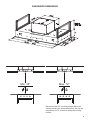 5
5
-
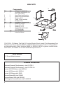 6
6
-
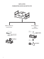 7
7
-
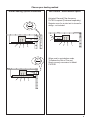 8
8
-
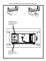 9
9
-
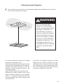 10
10
-
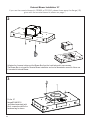 11
11
-
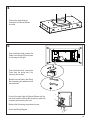 12
12
-
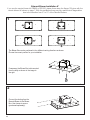 13
13
-
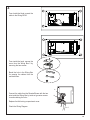 14
14
-
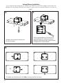 15
15
-
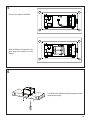 16
16
-
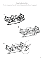 17
17
-
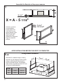 18
18
-
 19
19
-
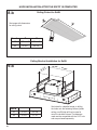 20
20
-
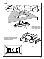 21
21
-
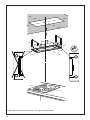 22
22
-
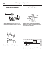 23
23
-
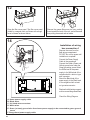 24
24
-
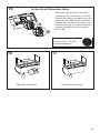 25
25
-
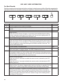 26
26
-
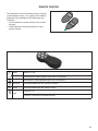 27
27
-
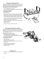 28
28
-
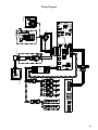 29
29
-
 30
30
-
 31
31
-
 32
32
-
 33
33
-
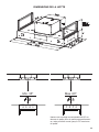 34
34
-
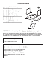 35
35
-
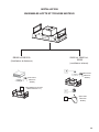 36
36
-
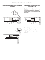 37
37
-
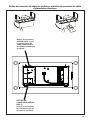 38
38
-
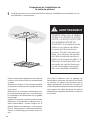 39
39
-
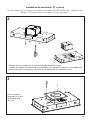 40
40
-
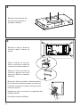 41
41
-
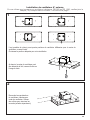 42
42
-
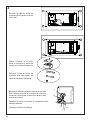 43
43
-
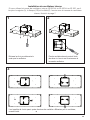 44
44
-
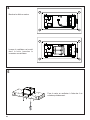 45
45
-
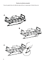 46
46
-
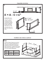 47
47
-
 48
48
-
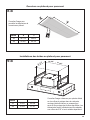 49
49
-
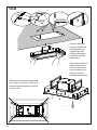 50
50
-
 51
51
-
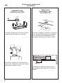 52
52
-
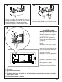 53
53
-
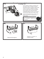 54
54
-
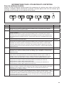 55
55
-
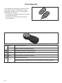 56
56
-
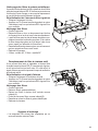 57
57
-
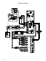 58
58
-
 59
59
-
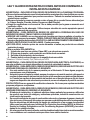 60
60
-
 61
61
-
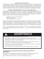 62
62
-
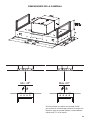 63
63
-
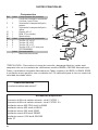 64
64
-
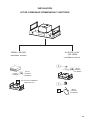 65
65
-
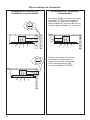 66
66
-
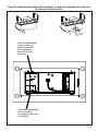 67
67
-
 68
68
-
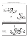 69
69
-
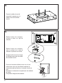 70
70
-
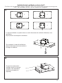 71
71
-
 72
72
-
 73
73
-
 74
74
-
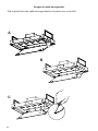 75
75
-
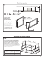 76
76
-
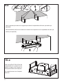 77
77
-
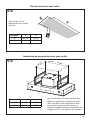 78
78
-
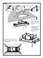 79
79
-
 80
80
-
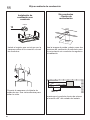 81
81
-
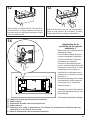 82
82
-
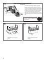 83
83
-
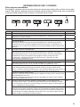 84
84
-
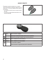 85
85
-
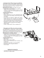 86
86
-
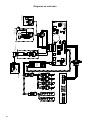 87
87
-
 88
88
-
 89
89
-
 90
90
-
 91
91
-
 92
92


Faber Stratus 36 SS Guía de instalación
- Categoría
- Campanas de cocina
- Tipo
- Guía de instalación
- Este manual también es adecuado para
en otros idiomas
- français: Faber Stratus 36 SS Guide d'installation
- English: Faber Stratus 36 SS Installation guide
Artículos relacionados
-
Faber High-Light 36 SSNB Guía de instalación
-
Faber Stratus 36 SS Guía de instalación
-
-
-
-
-
-
-
-