
TOOLS REQUIRED TABLE OF CONTENTS
7/16" (≈11 mm)
3/8" (≈10 mm)
5/16" (≈8 mm) Drill Bit
5/32" (≈4 mm) Drill Bit (*)
5/16" (≈8 mm) Masonry Drill Bit
Pour le français, voir la page 2. Para el español, ver la página 3.
ASSEMBLY INSTRUCTIONS
OUTSIDE
SHED
MODEL 60336
ITM./ART. 1902228
BEFORE ASSEMBLY:
• Assemble on a level platform
• At least 3 people recommended for setup
• Inspect all parts and hardware. Ensure all are
included using the
Parts Identifier
in the middle
of these instructions. The
Parts Identifier
, in
yellow, can be removed from the instructions for
quick reference
Icon Legend..................................................4
Warnings & Notices......................................5
Platform Construction...................................6
Truss & Beam Assembly.............................11
Transom & Gable Assembly........................17
Door Assembly.............................................26
Floor Assembly............................................40
Wall Assembly.............................................44
Shelving Installation...................................53
Door, Transom & Gable Installation............61
Parts Identifi er...........................................i–iv
Roof Assembly............................................76
Wall Hook Installation................................112
Door Alignment.........................................114
Shed Anchoring.........................................116
Cleaning & Care.......................................122
Registration............................................123
Warranty.................................................124
FOR OUTDOOR DOMESTIC USE ONLY!
IMPORTANT, RETAIN FOR FUTURE REFERENCE: READ CAREFULLY
QUESTIONS?
For Customer Service in mainland
Europe and the United Kingdom:
E-mail: [email protected]
CONTACT LIFETIME CUSTOMER SERVICE:
Call: 1-800-225-3865
(English, French, Spanish)
Live Chat:
www.lifetime.com/customerservice/home
(click on "LIVE CHAT" tab)
Model Number: 60336
Product ID:
(Not included—unless otherwise indicated*)

2
Légende des icônes......................................4
Avertissements et avis.................................5
Assemblage de la plate-forme.....................6
Assemblage des fermes et de la poutre....11
Assemblage de l’imposte et des pignons...17
Assemblage des portes..............................26
Assemblage du plancher............................40
Assemblage des murs................................44
Installation du rayonnage..........................53
Installation des portes, de l’imposte et des
pignons.......................................................61
Identifi cateur de pièces............................i–iv
Assemblage du toit....................................76
Installation des crochets muraux..............112
Alignement des portes..............................114
L’ancrage de l’abri.....................................116
Nettoyage et entretien...............................122
Enregistrement.........................................123
Garantie....................................................125
ITM./ART. 1902228
AVANT L’ASSEMBLAGE :
• Assembler sur une plate-forme nivelée
• Nous recommandons, au moins, 3 adultes pour
l’assemblage
• Examiner toutes les pieces et quincaillerie. Vérifier
qu’elles sont incluses en utilisant l’
Identificateur
de pièces
au milieu de ces instructions. Il est posssible
enlever l’
Identificateur de pièces
, en jaune, des
instructions pour référence rapide
For English, see page 1. Para el español, ver la página 3.
INSTRUCTIONS D’ASSEMBLAGE
MODÈLE n° 60336
OUTILS REQUIS SOMMAIRE
5/16 po (≈8 mm) Foret
5/16 po (≈8 mm) Foret à maçonnerie
ABRI
EXTÉRIEUR
5/32 po (≈4 mm) Foret (*)
POUR USAGE DOMESTIQUE EN EXTÉRIEURS SEULEMENT !
IMPORTANT, À CONSERVER POUR DE FUTURS BESOINS DE RÉFÉRENCE : À
LIRE SOIGNEUSEMENT
7/16 po (≈11 mm)
3/8 po (≈10 mm)
CONTACTER AUX SERVICES À LA CLIENTÈLE LIFETIME® :
Composer le 1-800-225-3865
(anglais, français, espagnol)
QUESTIONS ? N° de pièce : 60336
Référence du produit :
Entretien en direct:
www.lifetime.com/customerservice/home
(cliquer sur la languette « LIVE CHAT »)
Pour les services à la clientèle du
continent européen:
É-mail: [email protected]
(Non inclus — sauf indication contraire*)

3
Leyenda de íconos..................................................4
Advertencias y avisos............................................5
Ensamblaje de la plataforma...............................6
Ensamblaje de las cerchas y la viga..................11
Ensamblaje del travesaño y de las fachadas...17
Ensamblaje de las puertas.................................26
Ensamblaje del piso.............................................40
Ensamblaje de los muros....................................44
Instalación de la estantería................................53
Instalación de las puertas, del travesaño, y de
las fachadas.........................................................61
Identifi cador de piezas.......................................i–iv
Ensamblaje del tejado.........................................76
Instalación de los ganchos murales.................112
Alineación de la puertas...................................114
Anclaje de la caseta...........................................116
Limpieza y cuidado............................................122
Registro................................................................123
Garantía...............................................................126
ITM./ART. 1902228
ANTES DE ENSAMBLAR:
• Ensamblar sobre una plataforma nivelada
• Recomendamos, al menos, 3 adultos para el
ensamblaje
• Inspeccionar todas las piezas y el herraje. Verificar que
todos están incluidos usando el
Identificador de piezas
en el medio de estas instrucciones. Se puede quitar el
Identificador de piezas
, en amarillo, de las instrucciones
para referencia rápida
For English, see page 1. Pour le français, voir la page 2.
INSTRUCCIONES DE ENSAMBLAJE
CASETA
EXTERIOR
INSTRUMENTAL REQUERIDO ÍNDICE
5/16 in (≈8 mm) Broca
5/16 in (≈8 mm) Broca de albañilería
MODELO n° 60336
5/32 in (≈4 mm) Broca (*)
¡SÓLO PARA EL USO DOMÉSTICO EN EXTERIORES!
IMPORTANTE: CONSERVE PARA FUTURA REFERENCIA. LEA CUIDADOSAMENTE
7/16" (≈11 mm)
3/8" (≈10 mm)
PONERSE EN CONTACTO CON LOS SERVICIOS DE CLIENTES LIFETIME®:
Llamar : 1-800-225-3865
(inglés, francés, español)
¿PREGUNTAS? Número de pieza: 60336
ID del producto:
Chat en vivo:
www.lifetime.com/customerservice/home
(cliquear en la lengüeta «LIVE CHAT»)
Para el servicio a clientes en el
continente europeo: Correo electrónico:
(No incluido, salvo indicación contratia*)

4
• Indicates the parts/no parts required for a section.
• Indique les pièces à utiliser/qu’aucone pièce n’est requise pour une section.
• Indica las piezas que se usarán/que no necesitan en una sección.
• Indicates special heed should be taken when reading.
• Indique qu’une attention spéciale doit être portée à la lecture.
• Indica que uno debe prestar atención al leer.
• Indicates the hardware to be used for a section.
• Indique la quincaillerie à utiliser pour une section.
• Indica los artículos de ferretería que se usarán para una sección.
• Indicates the tools to be used for a section.
• Indique les outils à utiliser pour une section.
• Indica las herramientas que se utilizarán para una sección.
• Indicates the number of adults required to perform a specifi c step, e.g., 2, 3, 4, etc.
• Indique le nombre d’adultes requis pour e ectuer une étape spécifi que, p. ex., 2, 3, 4, etc.
• Indica el número de adultos requeridos para realizar un paso específi co, p.ej., 2, 3, 4, etc.
• Indicates no hardware required for a specifi c page or section.
• Indique qu’aucun matériel n’est requis pour une page précise.
• Indica que no se necesitan los artículos de ferretería para una página específi ca.
• Indicates to use/not use an electric drill for a specifi c step.
• Indique quand utiliser une/que ne pas utiliser de perceuse électrique pour une étape précise.
• Indica la utilización de/que no utilizar un taladro eléctrico para un paso específi co.
ICON LEGEND / LÉGENDE DES ICÔNES / SIGNIFICADO DE LOS ÍCONOS
• These nuts are centerlock nuts. They are designed to be tight; therefore, they will be harder to tighten. Tighten until fl ush with the metal or plastic.
• Ces écrous sont des écrous de blocage central. Ils sont conçus pour être serrés; de ce fait, ils seront plus di ciles à resserrer. Serrer jusqu’à ce qu’ils
soient au ras du métal ou du plastique.
• Estas tuercas son tuercas de bloqueo central. Están diseñadas para estar apretadas; por lo tanto, serán más difíciles de apretar. Apriételas hasta que
estén al ras del metal o plástico.

5
English:
• Failure to follow these warnings may result in serious injury or property damage and will void warranty.
• To ensure safety, do not attempt to assemble this product without following the instructions carefully.
• Consult all local building codes to verify if the shed requires a building permit.
• Verify the foundation is completely level before assembling the shed.
• Be aware that plastic pieces can be damaged by overtightening the screws. To avoid damage, we strongly recommend the use of a drill
with a low torque setting. A #2 Phillips screwdriver may also be used.
• Three capable adults are required for assembly.
• All who participate in the assembly process should wear safety glasses throughout the assembly.
• If using a ladder during assembly, use extreme caution.
• In heavy snowfall areas, we recommend removing snow from the roof. Remove the snow from the roof when the depth of snow
equals the length of your hand.
• Do not use or store hot objects near the product.
• Proper and complete assembly are essential to reduce the risk of accident or injury.
• When drilling through metal, beware of burrs, shavings and other sharp edges.
• During and after assembly, do not slide or lift the shed by pushing up on the roof. Move the shed by pushing on the corner panels only.
• Failure to anchor the shed may result in property damage and/or personal injury. The last section, Shed Anchoring, in this manual shows the
hardware you will need to complete the anchoring. You can fi nd the hardware at your local hardware store.
• Most injuries are caused by misuse and/or not following instructions. Use caution when using this product.
Français :
• Ne pas suivre ces avertissements peut entraîner des blessures graves ou des dommages à la propriété et annulera la garantie.
• Afi n d’assurer la sécurité, ne pas tenter d’assembler ce produit sans suivre attentivement les instructions.
• Consulter tous les codes du bâtiment afi n de vérifi er si l’abri nécessite un permis de construire.
• Vérifi er que la fondation est complètement à niveau avant l’assemblage de l’abri.
• Ne pas oublier que les pièces de plastique peuvent être endommagées en serrant trop les vis. Afi n d’éviter les dommages, nous
recommandons fortement l’utilisation d’une perceuse à faible couple. Un tournevis cruciforme nº 2 peut aussi être utilisé.
• Trois adultes en bonne condition physique sont nécessaires pour l’assemblage.
• Tout ceux qui participent au processus de l’assemblage doivent porter des lunettes de sécurité tout au long de l’assemblage.
• Si une échelle est utilisée pour l’assemblage, il faut être extrêmement prudent.
• Dans les zones de fortes tombées de neige, il est recommandé de dégager le toit. Enlever la neige du toit quand la profondeur est égale
à la longueur de la main.
• Ne pas utiliser ou entreposer des objets très chauds près de ce produit.
• Un bon assemblage complet est nécessaire pour réduire le risque d’accident ou de blessure.
• En perçant le métal, faire attention aux bavures, copeaux et autre bords aiguisés.
• Pendant et après l’assemblage, ne pas faire glisser ou soulever l’abri en poussant le toit vers le haut. Déplacer l’abri en poussant les
panneaux muraux angulaires seulement.
• Si vous n’ancrez pas votre abri, des dommages à la propriété et/ou des blessures peuvent en résulter. La dernière section, Ancrage de l’abri, de
ce manuel indique les matériaux nécessaires pour l’ancrage. Les matériaux se trouvent dans la quincaillerie locale.
• La majorité des blessures sont causées par une mauvaise utilisation et/ou le non suivi des instructions. Étre prudent en utilisant ce produit.
Español:
• No seguir estas advertencias puede resultar en lesiones graves o daños a la propiedad y anulará la garantía.
• A fi n de garantizar la seguridad, no intentar ensamblar este producto sin seguir cuidadosamente las instrucciones.
• Consultar todos los códigos de construcción locales para verifi car si el cobertizoo requiere un permiso de construcción.
• Verifi car que el concreto esté nivelado completamente antes de ensamblar el cobertizo.
• Tener en cuenta que las piezas de plástico pueden dañarse si los tornillos se aprietan de más. A fi n de evitar daños, lo exhortamos a que
use un taladro con función de torque bajo. También puede usarse un desatornillador Phillips no. 2.
• Se necesitan tres adultos para el ensamble.
• Todos los que participen en el proceso de ensamble debe usar anteojos de seguridad durante todo el ensamble.
• Si se usa una escalera durante el ensamblado, es preciso tener cuidado.
• En áreas de nevadas fuertes, recomendamos retirar la nieve del techo. Quitar la nieve del tejado cuando la profundidad de ella es igual
a la longitud de la mano.
• No usar ni guardar objetos calientes cerca del producto.
• El ensamblaje correcto y completo son esenciales para reducir el riesgo de accidente o lesión.
• Al perforar metal, tenga cuidado las rebabas, virutas y otros bordes afi lados.
• Durante y después del ensamblaje, no deslizar ni levantar el cobertizo para empujar en el tejado. Mover el cobertizo para empujar los
paneles murales angulares solamente.
• No anclar el cobertizo puede resultar en daños a la propiedad y/o en lesiones personales. La última sección, Anclaje de el cobertizo, en este
manual muestra el herraje necesaria para terminar el anclaje. Se encuentra el herraje en la ferretería local.
• La mayoría de las lesiones suceden a causa del mal uso y/o por no seguir las instrucciones. Tener precaución al usar este producto.
WARNINGS & NOTICES / AVERTISSEMENTS ET AVIS / ADVERTENCIAS Y AVISOS

6
PLATFORM CONSTRUCTION (MATERIALS NOT INCLUDED) / CONSTRUCTION DE LA PLATE-FORME (LES PIÈCES
NE SONT PAS INCLUSES) / CONSTRUCCIÓN DE LA PLATAFORMA (LOS MATERIALES NO SON INCLUIDOS)
1
• You must provide a platform on which to assemble your shed. Proper building permit documentation may be
required in your neighborhood. Consult all local building codes prior to assembling the shed. Before beginning
assembly, you must pour or construct a platform. There are two types:
• Concrete
• Wood Frame
Select the type, but know the surface must be leveled and fl at before installation. If the surface is not properly leveled and
fl at, the shed will not assemble correctly. Proper surface leveling will save you time in the long run, so please do not ignore
this step. We recommend a Concrete platform. It will be the most durable and long-lasting choice. The platform you choose must be built above
ground in order to avoid water pooling inside the shed. All lumber must be rated for outdoor use!
• Il faut construire une plate-forme sur laquelle assembler l’abri. Il est possible que le quartier exige une
documentation visant les permis de construire. Consulter tous les codes du bâtiment locaux, ainsi que les décrets
des villes et comtés, pour vérifi er que la construction de l’abri extérieur n’exige pas de permis de construire. Avant
de commencer l’assemblage, il faut couler ou construire une plate-forme. Il y à deux styles :
• béton
• cadre à bois
Sélectionner le style, mais savoir que la surface d’installation doit être de niveau et plate. Si la surface n’est pas correctement
de niveau et plate, l’assemblage de l’abri ne se fera pas correctement. Une surface bien de niveau fera gagner de temps
sur le long terme ; ne pas négliger pas cette étape. Nous recommandons une plate-forme en béton. Ce choix sera le plus durable. La
plate-forme choisie doit être construite au-dessus du sol afi n d’éviter l’accumulation d’eau à l’intérieur de l’abri. Tous le bois d’oeuvre doit être
approuvé pour l’usage à l’extérieur !
• Es preciso construir una plataforma sobre la cual usted debe ensamblar su caseta. Puede suceder que en el
vecindario se requiera la documentación apropiada de un permiso de construcción. Consultar todos los códigos
locales de construcción y los reglamentos de la ciudad y el municipio para asegurarse de que la construcción de
la caseta no requiera un permiso de construcción. Antes de comenzar el ensamble, es necesario verter o construir
una plataforma. Hay dos clases:
• concreto
• armazón de madera
Seleccionar la clase, mas saber que la superfi cie debe estar nivelada y plana antes de comenzar el ensamble. Si la superfi cie
no está nivelada y plana de manera adecuada, la caseta no podrá ensamblarse correctamente. La nivelación de la superfi cie
ahorrará tiempo de trabajo, por lo tanto, no ignorar este paso. Recomendamos una plataforma hecho de concreto. Será la elección más
perdurable. La plataforma debe estar construida arriba del suelo para evitar el afl ujo de agua dentro de la caseta. ¡Toda la madera debe estar
clasifi cada para el uso externo!

7
X SECTION 1 (CONTINUED) / SECTION 1 (SUITE) / SECCIÓN 1 (CONTINUACIÓN)
1 yd3 (≈0,77 m3)
!
CONCRETE REQUIRED / BÉTON REQUIS / CONCRETO REQUERIDO
CONCRETE PLATFORM / PLATE-FORME EN BÉTON / PLATAFORMA DE CONCRETO
1.1
• The concrete should be approximately 4" (≈10 cm) thick. The actual dimensions of the shed, at its widest and longest
points, are 100" x 100" (254 cm x 254 cm). Ensure you select a site that will accommodate these measurements. The fl oor
dimensions are a bit smaller than those of the roof; therefore, you will need to build a level platform of, at least, 91 1/4" x 91 1/4" (231,8 x 231,8
cm). These are the measurements of the platform—not the fl oor. The highest point of the shed is 93,3" (≈237,2 cm).
• Le béton doit être un épaisseur de ≈10 cm (4 po). Les dimensions réelles de votre abri, aux points les plus large et long,
sont 254 x 254 cm (100 x 100 po). S’assurer de sélectionner un site qui accommodera ces dimensions. Les dimensions du
plancher de l’abri sont plus petites que le toit ; ensuite, il faut créer une surface nivelée d’au moins 231,8 x 231,8 cm (91 1/4 po x 91 1/4 po). Ces
mesures sont de la plate-forme — non le plancher. Le plus haut point de l’abri est ≈237,2 cm (93,3 po).
• El concreto debe tener, por lo menos, ≈10 cm (4 in) de espesor. Las dimensiones reales de la caseta, a sus puntos más
ancho y largo, son 254 cm x 254 cm (100 x 100 in). Asegurarse de seleccionar un sitio que acomodará estas medidas. Las
dimensiones del piso de la caseta son más pequeñas que el tejado; por lo tanto, se necesita crear una superfi cie nivelada mínimo de 231,8 x
231,8 cm (91 1/4 in x 91 1/4 in). Estas medidas son las de la plataforma, no el piso. La altura de la caseta es ≈237,2 cm (93,3 in).
100 in/po (≈254 cm)
91 1/4 inpo(≈231,8 cm)
91 1/4 in/po (≈231,8 cm)
4 in/po (≈10 cm)
100 in/po (≈254 cm)
93,3 in/po (≈237,2 cm)

8
X SECTION 1 (CONTINUED) / SECTION 1 (SUITE) / SECCIÓN 1 (CONTINUACIÓN) 1
WOOD PLATFORM / PLATE-FORME EN BOIS PLATA / PLATAFORMA DE MADERA
1.2
WOOD REQUIRED / BOIS REQUIS / MADERA REQUERIDA
RIDA
• All lumber must be rated for outdoor use! The actual dimensions of the shed, at its widest and longest points, are 100" x 100"
(254 x 254 cm). Ensure you select a site that will accommodate these measurements. The fl oor dimensions are a bit smaller
than those of the roof; therefore, you will need to build a level platform of, at least, 91 1/4" x 91 1/4" (231,8 x 231,8 cm). The highest point of
the shed is 93,3" (≈237,2 cm). These are the measurements of the platform—not the fl oor.
• Tous le bois d’oeuvre doit être approuvé pour l’usage à l’extérieur ! Les dimensions réelles de l’abri, aux points les plus large et
long, sont 254 x 254 cm (100 po x 100 po). S’assurer de sélectionner un site qui accommodera ces dimensions. Les
dimensions du plancher de l’abri sont plus petites que le toit ; ensuite, il faut créer une surface nivelée de, au moins, 231,8 x 231,8 cm (91
1/4 po x 91 1/4 po). Ces mesures sont de la plate-forme — non le plancher. Le plus haut point de l’abri est ≈237,2 cm (93,3 po).
• ¡Toda la madera debe estar clasifi cada para el uso externo! Las dimensiones reales de la caseta, a sus puntos más ancho
y largo, son 254 x 254 cm (100 in x 100 in). Asegurarse de seleccionar un sitio que acomodará estas medidas. Las
dimensiones del piso de la caseta son más pequeñas que el tejado; entonces, se necesita crear una superfi cie nivelada de, al menos, 231,8 x
231,8 cm (91 1/4 in x 91 1/4 in). Estas medidas son las de la plataforma, no del piso. El punto más alto de la caseta es ≈237,2 cm (93,3 in).
100 in/po (≈254 cm)
91 1/4 in/po (≈231,8 cm)
91 1/4 in/po (≈231,8 cm)
100 in/po (≈254 cm)
93,3 in/po (≈237,2 cm)

9
X SECTION 1 (CONTINUED) / SECTION 1 (SUITE) / SECCIÓN 1 (CONTINUACIÓN)
91 1/4 in/po (≈231,8 cm)
88 1/4 in/po (≈224,2 cm)
91 1/4 in/po (≈231,8 cm)
16" (41 cm)
16" (41 cm)
16" (41 cm)
16" (41 cm)
16" (41 cm)
x8
1
!
TOOLS, PARTS, AND HARDWARE REQUIRED / OUTILS, PIÈCES, ET QUINCAILLERIE REQUIS / INSTRUMENTAL, PIEZAS, Y HERRAJE REQUERIDOS
• Ensure all lumber is treated and approved for outdoor use. Build frame to 91 1/4" x 91 1/4" (≈231,8 x 231,8 cm)
(outside dimensions).
• Vérifi er que le bois d’œuvre à été traité et approuvé pour l’utilisation à l’extérieur. Construire un cadre de ≈231,8 x
231,8 cm (91 1/4 po x 91 1/4 po) (dimensions extérieures).
• Asegurarse que la madera usada haya sido tratado y aprobado para el uso externo. Construir el armazón a ≈231,8
x 231,8 cm (91 1/4 in x 91 1/4 in) (dimensiones exteriores).
• To ensure studs are in the correct location for nailing plywood in the next step, start measuring from the corner 16"
(≈40,1 cm), and then measure from center to center.
• Pour être sûr d’avoir assez de montant pour clouer le contreplaqué dans le prochaine étape, commencer à mesurer
à partir de cette montant ≈40,1 cm (16 po) vers le centre du deuxième montant. Ensuite, mesurer de centre à centre
pour les montants restants.
• Para asegurarse que los montantes están en las ubicaciones correctas para el contrachapado en el paso siguiente,
comenzar a medir desde el borde del montante hasta el centro del próximo montante ≈40,1 cm (16 in). Luego, tomar
la medida de centro a centro en los montantes restantes.
WOOD PLATFORM / PLATE-FORME EN BOIS / PLATAFORMA DE MADERA
1.2.1
1.2.2
x20
Start Here / Commencer ici /
Comenzar aquí
91 1/4 in/po (≈231,8 cm)
88 1/4 in/po (≈224,2 cm)
91 1/4 in/po (≈231,8 cm)
16 in/po (40,1 cm)
2 in/po x 4 in/po x 91 1/4 in/po (≈5 cm x 10 cm x 231,8 cm) (x2)
2 in/po x 4 in/po x 88 1/4 in/po (≈5 cm x 10 cm x 224,2 cm) (x7)
16d 3 in/po (16d x ≈7,62 cm) (x28)

10
X SECTION 1 (CONTINUED) / SECTION 1 (SUITE) / SECCIÓN 1 (CONTINUACIÓN) 1
!
TOOLS, PARTS, AND HARDWARE REQUIRED / OUTILS, PIÈCES, ET QUINCAILLERIE REQUIS / INSTRUMENTAL, PIEZAS, Y HERRAJE REQUERIDOS
!
• Square the frame, measuring from corner to corner. Measurements A & B should be about the same length.
• Carrer le cadre en mesurant d’angle à angle. Les mesures " A " et " B " doivent être à peu près la même longeur.
• Cuadrar el armazón mediendo de esquina a esquina. Las medidas "A" y "B" deben ser approximadamente el mismo largo.
• Using nails, fasten the plywood to the frame. Then, drill 5/16" (≈8 mm) holes for drainage.
• En utilisant des clous, bien attacher le contreplaqué au cadre. Ensuite, percer des trous de ≈8 mm pour le drainage.
• Usando unos clavos, sujetar el contrachapado al armazón. Entonces, taladrar agujeros de ≈8 mm para el drenaje.
1.2.3
1.2.4
x48
A
B
43 1/4" x 91 1/4" x 3/4"
(≈109,9 cm x 231,8 cm x 1,9 cm)
48" x 91 1/4" x 3/4"
(≈121,9 cm x 231,8 cm x 1,9 cm)
x18!
• 5/16" (≈8 mm) Drainage Holes
• Agujeros para canalización de ≈8 mm
• Trous de drainage de ≈8 mm
8d 1 1/2 in/po (8d ≈3,81 cm) (x48)
48 in/po x 91 1/4 in/po x 3/4 in/po
(≈121,9 x 231,8 x 1,9 cm) (x1)
43 1/4 in/po x 91 1/4 in/po x 3/4 in/po
(≈109,9 x 231,8 x 1,9 cm) (x1)

11
TRUSS & BEAM ASSEMBLY / ASSEMBLAGE DE LA POUTRE ET LES FERMES / ENSAMBLAJE DE LA VIGA Y
LAS CERCHAS
2
7/16" (≈11 mm) (x1)
GLH
Metal Parts / Piezas de metal / Pièces en métal
Hardware Bag / Bolsa de herraje / Sac de quincaillerie
PARTS REQUIRED / PIEZAS REQUERIDAS / PIÈCES REQUISES
HARDWARE REQUIRED / HERRAJE REQUERIDO / QUINCAILLERIE REQUISE
GJZ (x8)
GQO (x8)
GKS (x8)
GKG (x4)
GKT (x1)
GKW (x3)
GKC (x2)
DAH (x20)
BLB (x12)
ADC (x1)
GKV (x3)
TOOLS REQUIRED (NOT INCLUDED) / OUTILS REQUIS (NON INCLUS) / INSTRUMENTAL REQUERIDO
(NO INCLUIDO)

12
TOOLS AND HARDWARE REQUIRED / INSTRUMENTAL Y HERRAJE REQUERIDOS / OUTILS ET QUINCAILLERIE REQUIS
X SECTION 2 (CONTINUED) / SECCIÓN 2 (CONTINUACIÓN) / SECTION 2 (SUITE)
GKT
GKT
GQO
GQO
GJZ
GJZ
• Attach the six (6) “L” brackets (GQO) to the beam (GKT) using six (6) screws (GJZ). Do not overtighten.
• Attacher six (6) supports en « L » (GQO) à la poutre (GKT) à l’aide de six (6) vis (GJZ). Ne pas serrer excessivement.
• Sujetar seis (6) soportes en «L» (GQO) a la viga (GKT) usando seis (6) tornillos (GJZ). No apretar demasiado.
GJZ (x6)
GQO (x6)
2.1
ADC (x1)

13
TOOLS AND HARDWARE REQUIRED / INSTRUMENTAL Y HERRAJE REQUERIDOS / OUTILS ET QUINCAILLERIE REQUIS
X SECTION 2 (CONTINUED) / SECCIÓN 2 (CONTINUACIÓN) / SECTION 2 (SUITE)
7/16"
(≈11 mm)
• Attach a vertical truss support (GKC) to each end of the beam with two (2) gussets (GKG). Do not overtighten.
• Attacher un support vertical de la ferme (GKC) à chaque extrémité de la poutre à l’aide de deux (2) goussets (GKG). Ne pas
serrer excessivement.
• Sujetar un soporte vertical de la cercha (GKC) a cada extremo de la viga usando dos (2) placas de refuerzo (GKG). No apretar
demasiado.
• The “L” brackets (GQO) from step 2.1 are on top.
• Les supports en « L » (GQO) de l’étape 2.1 sont en
haut.
• Los soportes en «L» del paso 2.1 están arriba.
2.2
GKS (x8)
GKC
GKC
GKC
GKG
GKG
GKS
GKS
GKS
GKS
DAH
DAH
DAH (x8)

14
TOOLS AND HARDWARE REQUIRED / INSTRUMENTAL Y HERRAJE REQUERIDOS / OUTILS ET QUINCAILLERIE REQUIS
X SECTION 2 (CONTINUED) / SECCIÓN 2 (CONTINUACIÓN) / SECTION 2 (SUITE)
• Attach an “L” bracket (GQO) to the end of each vertical support using one (1) screw (GJZ) each. Do not overtighten. Set the assembly aside.
• Attacher un support en « L » (GQO) à l’extrémité de chaque support vertical à l’aide d’une (1) vis (GJZ) chacun. Ne pas serrer
excessivement. Mettre de côté l’assemblage.
• Sujetar un soporte en «L» (GQO) al extremo de cada soporte vertical usando un (1) tornillo (GJZ) cada uno. No apretar demasiado. Dejar el
ensamble de lado.
2.3
GJZ (x2)
GQO (x2)
GJZ
GQO

15
TOOLS AND HARDWARE REQUIRED / INSTRUMENTAL Y HERRAJE REQUERIDOS / OUTILS ET QUINCAILLERIE REQUIS
X SECTION 2 (CONTINUED) / SECCIÓN 2 (CONTINUACIÓN) / SECTION 2 (SUITE)
• Slide a short gutter channel (GKV) into a long truss gutter channel (GKW) and align the four square holes.
• Faire glisser un canal de gouttière court (GKV) dans un canal de gouttière long (GKW) et aligner les quatre trous carrés.
• Deslizar un canalón corto (GKV) dentro de un canalón largo (GKW) y alinear los cuatro agujeros cuadrados.
BLB (x4)
BLB (x4)
GKV
GKW
• Insert four (4) bolts (BLB) through the square holes from the inside out.
• Insérer quatre (4) boulons (BLB) à travers les quatre trous carrés de l’intérieur vers l’extérieur.
• Insertar cuatro (4) pernos (BLB) por les agujeros cuadrados de adentro hacia afuera.
2.4
2.5

16
TOOLS AND HARDWARE REQUIRED / INSTRUMENTAL Y HERRAJE REQUERIDOS / OUTILS ET QUINCAILLERIE REQUIS
X SECTION 2 (CONTINUED) / SECCIÓN 2 (CONTINUACIÓN) / SECTION 2 (SUITE)
• Secure each bolt with a nut (DAH). Do not overtighten.
• Bien attacher chaque boulon avec un écrou (DAH). Ne pas serrer excessivement.
• Apretar bien cada perno con una tuerca (DAH). No apretar demasiado.
DAH (x12)
DAH
DAH
DAH
DAH
2.6
• Repeat steps 2.4–2.6 two more times. Set the gutter channels aside.
• Répéter les étapes 2.4 – 2.6 de fois de plus. Mettre de côté les canaux de gouttière.
• Repetir los pasos 2.4–2.6 dos veces más. Dejar de lado los canalones.
2.7
BLB (x8)
7/16"
(≈11 mm)

17
TRANSOM & GABLE ASSEMBLY / ASSEMBLAGE DE L’IMPOSTE ET DES PIGNONS / ENSAMBLAJE DEL MONTANTE Y DE LAS
FACHADAS
3
GKP (x8)
GKR (x2)
GLF (x1)
GKQ (x4)
GKH (x3)
GKD (x2)
GIE (x1)
GIF (x1)
GKF (x2)
GLI
Metal Part / Pièce en métal / Pieza de metal
Plastic Parts / Pièces en plastique / Piezas de plástico
Hardware Bag / Sac de quincaillerie / Bolsa de herraje
PARTS REQUIRED / PIÈCES REQUISES / PIEZAS REQUERIDAS
HARDWARE REQUIRED / QUINCAILLERIE REQUISE / HERRAJE REQUERIDO
ADK (x8)
GJZ (x2)
ADZ (x72)
AEE (x8)
ADX (x8)
EPH (x3) EPI (x3)
GNY (x2)

18
TRANSOM & GABLE ASSEMBLY / ASSEMBLAGE DE L’IMPOSTE ET DES PIGNONS / ENSAMBLAJE DEL MONTANTE Y DE LAS
FACHADAS
3
Plastic Parts / Pièces en plastique / Piezas de plástico
PARTS REQUIRED / PIÈCES REQUISES / PIEZAS REQUERIDAS
GDT (x1)
GDU (x1)
GDV (x1)
TOOLS REQUIRED (NOT INCLUDED) / OUTILS REQUIS (NON INCLUS) / INSTRUMENTAL REQUERIDO (NO INCLUIDO)

19
TOOLS AND HARDWARE REQUIRED / OUTILS ET QUINCAILLERIE REQUIS / INSTRUMENTAL Y HERRAJE REQUERIDOS
X SECTION 3 (CONTINUED) / SECTION 3 (SUITE) / SECCIÓN 3 (CONTINUACIÓN)
GKP GKQ
GKP
GNY
GNY
ADK
ADK
ADK
ADK
ADK
ADK
ADK
• Insert two (2) bolts (GKP) through a support (GKQ). Repeat this step for
the other three supports.
• Insérer deux (2) boulons (GKP) à travers un support (GKQ). Répéter
cette étape pour les trois autres supports.
• Insertar dos (2) pernos (GKP) por un soporte (GKQ). Repetir este paso para
los otros tres soportes.
TRANSOM FRAME ASSEMBLY / ASSEMBLAGE DU CADRE DE L’IMPOSTE / ENSAMBLAJE DEL ARMAZÓN DEL TRAVESAÑO
• Set the rectangular holes in the two (2) headers (GKR) over the screws in the supports and secure with eight (8) nuts (ADK).
Attach two (2) transom-to-gable brackets (GNY) to each bottom corner. Only hand-tighten these nuts for now.
• Mettre les trous rectangulaires dans les deux (2) linteaux (GKR) sur les vis dans les supports et bien les attacher à l’aide
de huit (8) écrous (ADK). Attacher les deux (2) supports pour l’imposte au pignon (GNY) à chaque coin inférieur. Serrer ces écrous seulement à la main en ce
moment.
• Colocar los agujeros rectamgulares en los dos (2) dinteles (GKR) sobre los tornillos en los soportes y fi jarlos bien usando
ocho (8) tuercas (ADK). Fijar los dos (2) soportes para el travesaño a la fachada (GNY) a cada esquina inferior. Apretar estas tuercas sólo a mano en este momento.
3.1
3.2
GKP (x8) ADK (x8)
Only hand-tighten these nuts
Serrer ces écrous à la main seulement
Apretar estas tuercas sólo a mano
GNY (x2)
• Flat side down
• Côté plat vers le bas
• Lado plano hacia abajo
ADK
ADK
GNY

20
TOOLS AND HARDWARE REQUIRED / OUTILS ET QUINCAILLERIE REQUIS / INSTRUMENTAL Y HERRAJE REQUERIDOS
X SECTION 3 (CONTINUED) / SECTION 3 (SUITE) / SECCIÓN 3 (CONTINUACIÓN)
3.3 • Secure the upper deadbolt bracket (GLF) to the transom using two (2) screws (GJZ). Tighten securely. Please note the orientation of the bracket
and the positions of the supports. Set the assembly aside.
• Bien attacher le support du verrou supérieur (GLF) à l’imposte à l’aide de deux (2) vis (GJZ). Bien serrer. Veiller à noter l’orientation du
support du verrou et les endroits des supports verticaux. Mettre l’assemblage de côté.
• Fijar bien el soporte del cerrojo superior (GLF) al montante usando dos (2) tornillos (GJZ). Apretar bien. Tener en cuenta la orientación del cerrojo
y las ubicaciones de los soportes verticales. Dejar el ensamble de lado.
• The supports are underneath the headers.
• Les supports verticaux se trouvent sous les linteaux.
• Los soportes verticales están debajo de los dinteles.
GJZ (x2)
GJZ
GJZ
GLF
GLF (x1)

21
TOOLS AND HARDWARE REQUIRED / OUTILS ET QUINCAILLERIE REQUIS / INSTRUMENTAL Y HERRAJE REQUERIDOS
X SECTION 3 (CONTINUED) / SECTION 3 (SUITE) / SECCIÓN 3 (CONTINUACIÓN)
3.4 TRANSOM ASSEMBLY / ASSEMBLAGE DE L’IMPOSTE / ENSAMBLAJE DEL TRAVESAÑO
• There is a narrow groove (illustrated in black) running along the outside of the window on the transom (GDT).
Starting at the top, left corner of the groove in the left window, lay an 1/8" (≈3 mm) strip of Butyl Tape (EPI) into the groove.
Do not worry about getting the strip completely into the groove just yet—simply lay the strip over the groove. Do not press the strip into the groove. Work your way
downward (1), and curve to go along the bottom (2) of the window. Curve your way upward (3) and then along the top (4)
of the window until you’re back where you started. Clip o any excess. Repeat this step for the other two windows. Each roll of butyl tape (EPI) covers
one square window.
• Une rainure étroite (illustrée en noir) se trouve le long du bord de chacune des trois fenêtres à l’arrière de
l’imposte. Partant du coin supérieur gauche de la rainure de la fenêtre gauche, étendre une goutte de ≈3 mm
(1/8 po) de ruban de caoutchouc butyl (EPI) dans la rainure. Ne pas s’inquiéter si la goutte n’est pas complètement dans la
rainure en ce moment — ne faire que déposer la goutte sur la rainure. Ne pas pousser la goutte dans la rainure. Travailler
vers le bas (1), et courber pour atteindre le bas (2) de la fenêtre. Courber vers le haut (3), puis le long du haut (4)
de la fenêtre jusqu’à revenir au point de départ. Couper de l’excédent. Répéter cette étape pour les deux fenêtres de plus.
Chaque rouleau de ruban (EPI) couvre une fenêtre.
• Hay una ranura angosta (ilustrada en negro) bordeando cada una de las tres ventanas en la superfi cie posterior del
travesaño. Comenzando desde arriba, en la esquina izquierda de la ranura en la ventana izquierda, aplicar una línea
de ≈3 mm (1/8 in) de cinta butílica (EPI) en la ranura. Ne preocuparse por poner la cinta, mas solamente ponga la cinta sobre la
ranura. No presionar la cinta dentro de la ranura. Seguir hacia abajo (1), y curvearla a lo largo del borde inferior (2) de
la ventana. Curvearla hacia arriba (3) y, entonces, a lo largo del borde superior (4) de la ventana hasta estar al punto de
partida. Cortar el exceso. Repetir este paso para las otras dos ventanas. Cada rollo de cinta (EPI) cubre una ventana.
Groove / Rainure / Ranura
EPI (x3)
1
2
3
4

22
TOOLS AND HARDWARE REQUIRED / OUTILS ET QUINCAILLERIE REQUIS / INSTRUMENTAL Y HERRAJE REQUERIDOS
X SECTION 3 (CONTINUED) / SECTION 3 (SUITE) / SECCIÓN 3 (CONTINUACIÓN)
3.5 • Peel the protective fi lm from both sides of the three (3) transom window panes (GKH). Secure the window panes to
the transom (GDW) using fourteen (14) screws (ADZ) each.
• Enlever la fi lm protecteur des deux côtés des trois (3) carreaux de l’imposte (GKH). Bien attacher les carreaux à
l’imposte (GDW) à l’aide de quatorze (14) vis (ADZ) chacun.
• Pelar la película protectora de ambos lados de las tres (3) hojas del montante (GKH). Fijar bien las hojas al montante
(GDW) usando catorce (14) tornillos (ADZ) cada una.
ADZ (x42)
GDW
ADZ (x14)
GKH
ADZ (x14)
ADZ (x14)
GKH
GKH
GKH

23
TOOLS AND HARDWARE REQUIRED / OUTILS ET QUINCAILLERIE REQUIS / INSTRUMENTAL Y HERRAJE REQUERIDOS
X SECTION 3 (CONTINUED) / SECTION 3 (SUITE) / SECCIÓN 3 (CONTINUACIÓN)
3.6 GABLE ASSEMBLY / ASSEMBLAGE DES PIGNONS / ENSAMBLAJE DE LAS FACHADAS
EPH (x3)
• There is a narrow groove (illustrated in black) running around the window on the back of each gable. Starting at the top,
left corner of the groove in the left gable, lay an 1/8” (≈3 mm) bead of butyl tape (EPH) into the groove. Do not worry about getting
the bead completely into the groove just yet—simply lay the bead over the groove. Do not press the bead into the groove. Work your way
downward (1), and curve to go along the bottom (2) of the window. Curve your way upward (3) and then along the top (4) of
the window until you’re back where you started. Clip off any excess. Each gable requires about 1 1/2 rolls of butyl tape (EPH). Repeat this
step for the other gable but start at the top right and work your way counter-clockwise.
• Une rainure étroite (illustrée en noir) se trouve le long du bord de la fenêtre sur la superfi cie arrière de chaque pignon.
Partant du coin supérieur gauche de la rainure du pignon gauche, étendre une goutte de ≈3 mm (1/8 po) de ruban de
caoutchouc butyl (EPH) dans la rainure. Ne pas s’inquiéter si la goutte n’est pas complètement dans la rainure en ce moment — ne faire que
déposer la goutte sur la rainure. Ne pas pousser la goutte dans la rainure. Travailler vers le b36as (1), et courber pour atteindre le
bas (2) de la fenêtre. Courber vers le haut (3), puis le long du haut (4) de la fenêtre jusqu’à revenir au point de départ. Couper
de l’excédent. Chaque pignon exige à peu près 1 1/2 rouleaux de ruban de caoutchouc butyl (EPH). Répéter cette étape pour l’autre fachada mais
commencer au coin supérieur droit et travailler dans le sens contraire des aiguilles d’une montre.
• Hay una ranura angosta (ilustrada en negro) bordeando la ventana en la superfi cie posterior de la fachada. Comenzando
desde arriba, en la esquina izquierda de la ranura en la ventana izquierda, aplicar una línea de ≈3 mm (1/8 in) de cinta
butílica (EPH) en la ranura. Ne preocuparse por poner la cinta, mas solamente ponga la cinta sobre la ranura. No presionar la cinta dentro de la
ranura. Seguir hacia abajo (1), y curvearla a lo largo del borde inferior (2) de la ventana. Curvearla hacia arriba (3) y, entonces,
a lo largo del borde superior (4) de la ventana hasta estar al punto de partida. Cortar el exceso. Cada fachada requiere 1 1/2 rollos de
cinta butílica (EPH). Repetir este paso para la otra fachada mas comenzar desde arriba en la esquina derecha y aplicar en sentido antihorario.
1
2
3
4

24
TOOLS AND HARDWARE REQUIRED / OUTILS ET QUINCAILLERIE REQUIS / INSTRUMENTAL Y HERRAJE REQUERIDOS
X SECTION 3 (CONTINUED) / SECTION 3 (SUITE) / SECCIÓN 3 (CONTINUACIÓN)
ADZ (x15)
ADX (x4) AEE (x4)
3.7
GIF (x1) GKF (x1)
• Peel the protective film from both sides of the three (3) transom window panes (GKH). Secure one (1) window pane (GKD)
to the right gable (GDV) using fifteen (15) screws (ADZ).
• Enlever la film protecteur des deux côtés des trois (3) carreaux de l’imposte (GKH). Bien attacher un (1) carreau (GKD)
au pignon droit (GDV) à l’aide de quinze (15) vis (ADZ).
• Pelar la película protectora de ambos lados de las tres (3) hojas del montante (GKH). Fijar bien una (1) hoja (GKD) a la
fachada derecha (GDV) usando quince (15) tornillos (ADZ).
3.8 • Secure a vent (GIF) and screen (GKF) to the right gable (GDV) using four (4) screws (ADX) and washers (AEE).
• Bien attacher un évent (GIF) et une moustiquaire (GKF) au pignon droit (GDV) à l’aide de quatre (4) vis (ADX) et rondelles
(AEE).
• Fijar bien una rejilla de ventilación (GIF) y un mosquitero (GKF) a la fachada derecha (GDV) usando cuatro (4) tornillos
(ADX) y rondanas (AEE).
GKD
ADZ (x15)
GKD
GDV
ADX (x4) / AEE (x4)
GDV
GKF
GIF

25
TOOLS AND HARDWARE REQUIRED / OUTILS ET QUINCAILLERIE REQUIS / INSTRUMENTAL Y HERRAJE REQUERIDOS
X SECTION 3 (CONTINUED) / SECTION 3 (SUITE) / SECCIÓN 3 (CONTINUACIÓN)
ADZ (x15)
ADX (x4)
AEE (x4)
GIE (x1) GKF (x2)
3.9 • Secure a vent (GIF) and screen (GKF) to the left gable (GDU) using four (4) screws (ADX) and washers (AEE).
• Bien attacher un évent (GIF) et une moustiquaire (GKF) au pignon droit (GDV) à l’aide de quatre (4) vis (ADX) et rondelles (AEE).
• Fijar bien una rejilla de ventilación (GIF) y un mosquitero (GKF) a la fachada derecha (GDV) usando cuatro (4) tornillos (ADX) y rondanas (AEE).
GDU

26
LEFT DOOR ASSEMBLY / ASSEMBLAGE DE LA PORTE GAUCHE / ENSAMBLAJE DE LA PUERTA IZQUIERDA
4
BDJ (x1)
BBH (x1)
EOY (x1)
AAB (x2)
AEB (x2)
AEE (x3)
ACH (x2)
GJZ (x7)
GLJ
Metal Parts / Pièces en métal / Piezas de metal
Hardware Bags / Sacs de quincaillerie / Bolsas de herraje
Plastic Parts / Pièces en plastique / Piezas de plástico
PARTS REQUIRED / PIÈCES REQUISES / PIEZAS REQUERIDAS
HARDWARE REQUIRED / QUINCAILLERIE REQUISE / HERRAJE REQUERIDO
BYZ (x3)
DGR (x1) DGS (x1)
Upper / Supérieur / Superior
Lower / Inférieur / Inferior
GJR (x1)
GHO (x1)
GJS (x1)
GJT (x1)
GJQ (x1)
GLY (x1)
TOOLS REQUIRED (NOT INCLUDED—UNLESS INDICATED OTHERWISE*) / OUTILS REQUIS (NON INCLUS — SAUF
INDICATION CONTRAIRE*) / INSTRUMENTAL REQUERIDO (NO INCLUIDO, SALVO INDICACIÓN CONTRARIA*)
ADC (x1)*

27
TOOLS AND HARDWARE REQUIRED / OUTILS ET QUINCAILLERIE REQUIS / INSTRUMENTAL Y HERRAJE REQUERIDOS
X SECTION 4 (CONTINUED) / SECTION 4 (SUITE) / SECCIÓN 4 (CONTINUACIÓN)
GJT
BBH
BDJ
• Align these holes
• Aligner ces trous
• Alinear estos agujeros
• Holes
• Trous
• Agujeros
• Slide a square tube (GJT) into the square hole at the bottom of the Left
Door (BDJ) until about 6" (≈15 cm) of the tube hang out of the hole.
• Faire glisser un tube carré (GJT) dans le trou carré au bord inférieur de
la porte gauche (BDJ) jusqu’à ce que environ ≈15 cm (6 po) étendent du
trou.
• Deslizar un tubo cuadrado (GJT) en el orifi cio cuadrado a la parte inferior
de la puerta izquierda (BDJ) hasta que unos ≈15 cm (6 in) cuelguen del
agujero.
• Insert the end cap (BBH) into the end of the square tube and continue inserting the tube until it is fl ush with the
bottom of the door. Align the two holes in the tube with the two holes in the door. If necessary, gently tap with a
rubber mallet.
• Insérer un capuchon (BBH) dans l’extrémité du tube carré et continuer à insérer le
tube jusqu’à ce qu’il soit à ras del borde inférieur de la porte. Aligner les deux
trous dans le tube avec les deux trous dans la porte. Si besoin, frapper
soigneusement avec un maillet en caoutchouc.
• Insertar un tapón (BBH) en el extremo del tubo cuadrado y
continuar a insertar el tubo hasta que esté al ras del borde
inferior de la puerta. Alinear los dos agujeros en el tube
con ellos en la puerta. Si es necesario, golpear
cuidadosamente con un mazo de goma.
4.1
4.2
BBH (x1)

28
TOOLS AND HARDWARE REQUIRED / OUTILS ET QUINCAILLERIE REQUIS / INSTRUMENTAL Y HERRAJE REQUERIDOS
X SECTION 4 (CONTINUED) / SECTION 4 (SUITE) / SECCIÓN 4 (CONTINUACIÓN)
• Attach the door latch bracket (EOY) to the door using the hardware indicated. Only hand-tighten for now.
• Attacher le support du loquet de la porte (EOY) à la porte à l’aide de la quincaillerie indiquée. Serrer à la main en ce
moment seulement.
• Fijar el soporte del cerrojo de la puerte (EOY) a la puerta usando el herraje indicado. Apretarlo sólo a mano en este
momento.
4.3
AAB
AEB
AAB
AEB
EOY
ACH ACH
EOY (x1)
AAB (x2)
AEB (x2)
ACH (x2)

29
TOOLS AND HARDWARE REQUIRED / OUTILS ET QUINCAILLERIE REQUIS / INSTRUMENTAL Y HERRAJE REQUERIDOS
X SECTION 4 (CONTINUED) / SECTION 4 (SUITE) / SECCIÓN 4 (CONTINUACIÓN)
4.4 • Turn the door onto its front. There are seven small impressions (divots) running along the edge of the door—two
at each end and three inbetween. Using the 5/32" (≈4 mm) drill bit (GHO) included and an electric drill, drill through the
divots and into the square tube. Do not drill all the way through the door.
• Poser la porte sur sa face avant. Il y a sept petites impressions (marques) le long du bord de la porte — deux a
chaque extrémité et trois entre elles. À l’aide du foret de 5/32" (≈4 mm) (GHO) inclus et d’une perceuse électrique, percer
les marques et dans le tube carré. Ne pas percer de face en face.
• Colocar la puerta sobre la cara delantera. Hay siete mellas pequeñas (marcas) a lo largo del borde de la puerta, dos
a cada extremo y tres entre ellas. Usando la broca de 5/32" (≈4 mm) (GHO) uncluida y un taladro eléctrico, taladrar las
marcas en la puerta y dentro el tubo cuadrado. No taladrar la puerta por completo.
GHO
• When drilling through metal, beware of burrs, shavings and other sharp edges.
• En perçant le métal, faire attention aux bavures, copeaux de métal et autres bords aiguisés.
• Al perforar metal, tenga cuidado con las rebabas, virutas y otros bordes afilados.
WARNING / AVERTISSEMENT / ADVERTENCIA
! !

30
TOOLS AND HARDWARE REQUIRED / OUTILS ET QUINCAILLERIE REQUIS / INSTRUMENTAL Y HERRAJE REQUERIDOS
X SECTION 4 (CONTINUED) / SECTION 4 (SUITE) / SECCIÓN 4 (CONTINUACIÓN)
4.5 • Set the inner door channel (GJQ) onto the door as shown. Align the three holes in the channel with the three holes in the
door. Secure the channel to the door using an electric drill and three (3) screws (GJZ).
• Mettre le canal intérieur de la porte (GJQ) sur la porte comme indiqué. Aligner les trois trous dans le canal avec les trous
trous dans la porte. Fixer le canal à la porte à l’aide d’une perceuse électrique et trois (3) vis (GJZ).
• Colocar el canal interior de la puerta (GJQ) sobre la puerta como se muestra. Alinear los tres agujeros en el canal con los
tres agujeros en la puerta. Fijar el canal a la puerta usando un taladro eléctrico y tres (3) tornillos (GJZ).
GJQ
GJZ
GJZ
GJZ
GJZ (x3)
ADC

31
TOOLS AND HARDWARE REQUIRED / OUTILS ET QUINCAILLERIE REQUIS / INSTRUMENTAL Y HERRAJE REQUERIDOS
X SECTION 4 (CONTINUED) / SECTION 4 (SUITE) / SECCIÓN 4 (CONTINUACIÓN)
4.6 • Secure the upper and lower latches (DGS and DGR) to the door using two (2) screws (GJZ) each. The latches should move
freely. If not, loosen the screws a tad.
• Bien attacher les loquets supérieur et inférieur (DGS et DGR) à la porte à l’aide de deux (2) vis (GJZ) chacun. Les loquets
doivent se déplacer librement. Si non, desserrer les vis un peu.
• Fijar bien los cerrojos superior e inferior (DGS y DGR) a la puerta usando dos (2) tornillos (GJZ) cada uno. Los cerrojos
deben moverse libremente. Si no, afl ojar los tornillos un poco.
DGS
GJZ
GJZ
GJZ
GJZ
DGR
GJZ (x4)
DGR (x1)
DGS (x1)
Upper / Supérieur / Superior
Lower / Inférieur / Inferior
ADC

32
TOOLS AND HARDWARE REQUIRED / OUTILS ET QUINCAILLERIE REQUIS / INSTRUMENTAL Y HERRAJE REQUERIDOS
X SECTION 4 (CONTINUED) / SECTION 4 (SUITE) / SECCIÓN 4 (CONTINUACIÓN)
4.7 • Attach the front and rear handle pieces (GJR and GJS) together. Secure the handle to the door using the hardware indicated.
• Attacher les parties avant et arrière de la poignée (GJR et GJS). Bien fi xer la poignée à la porte à l’aide de la quincaillerie indiquée.
• Conectar las piezas delantera y trasera del picaporte (GJR y GJS). Fijar bien el picaporte a la puerta usando el herraje indicado.
GJR
GJS
BYZ (x3)
BYZ
BYZ
BYZ
AEE
AEE AEE
AEE (x3)

33
TOOLS AND HARDWARE REQUIRED / OUTILS ET QUINCAILLERIE REQUIS / INSTRUMENTAL Y HERRAJE REQUERIDOS
X SECTION 4 (CONTINUED) / SECTION 4 (SUITE) / SECCIÓN 4 (CONTINUACIÓN)
4.8 • Slide a hinge tube (GLY) into the hole at the bottom of the door. If necessary, use a rubber mallet to gently tap the tube into
place. This tube has a notch at both ends.
• Faire glisser un tube de charnière (GLY) dans le trou au fond de la porte. Si besoin, employer un maillet en caoutchouc pour
taper le tube en place. Ce tube a une encoche à chaque extrémité.
• Deslizar un tubo de bisagra (GLY) en el orifi cio al fondo de la puerta. Si es necesario, usar un mazo de goma para golpear el
tube en su lugar. Este tubo tiene una muesca a cada extremo.
Notches
Encoches
Muescas
GLY

34
RIGHT DOOR ASSEMBLY / ASSEMBLAGE DE LA PORTE DROITE / ENSAMBLAJE DE LA PUERTA DERECHA
5
EOZ (x1)
GLK
Hardware Bag / Sac de quincaillerie / Bolsa de herraje
HARDWARE REQUIRED / QUINCAILLERIE REQUISE / HERRAJE REQUERIDO
Metal Parts / Pièces en métal /Piezas de metal
Plastic Parts / Pièces en plastique / Piezas de plástico
PARTS REQUIRED / PIÈCES REQUISES / PIEZAS REQUERIDAS
BDK (x1)
GJT (x1)
GLY (x1)
GJR (x1) GJS (x1)
BBH (x1)
AEE (x3)
BYZ (x3)
EPA (x1)
FJP (x1)
AAB (x2)
ADK (x2)
ACH (x2)
FUA (x2)
GJZ (x1)
GHO (x1)*
TOOLS REQUIRED (NOT INCLUDED—UNLESS INDICATED OTHERWISE*) / OUTILS REQUIS (NON INCLUS — SAUF
INDICATION CONTRAIRE*) / INSTRUMENTAL REQUERIDO (NO INCLUIDO, SALVO INDICACIÓN CONTRARIA*)
ADC (x1)*

35
TOOLS AND HARDWARE REQUIRED / OUTILS ET QUINCAILLERIE REQUIS / INSTRUMENTAL Y HERRAJE REQUERIDOS
X SECTION 5 (CONTINUED) / SECTION 5 (SUITE) / SECCIÓN 5 (CONTINUACIÓN)
5.1
5.2
BBH (x1)
BDK
GJT
BBH
• Slide a square tube (GJT) into the square hole at the bottom of the right door (BDK) until about 6" (≈15 cm) of the tube
hang out of the hole.
• Faire glisser un tube carré (GJT) dans le trou carré au bord inférieur de la porte droite (BDK) jusqu’à ce que environ
≈15 cm (6 po) étendent du trou.
• Deslizar un tubo cuadrado (GJT) en el orifi cio cuadrado a la parte inferior de la puerta derecha (BDK) hasta que unos
≈15 cm (6 in) cuelguen del agujero.
• Insert the end cap (BBH) into the end of the square tube and continue inserting the tube until it is fl ush with the
bottom of the door. Align the two holes in the tube with the two holes in the door. If necessary, gently tap with a
rubber mallet.
• Insérer un capuchon (BBH) dans l’extrémité du tube carré et continuer à insérer le
tube jusqu’à ce qu’il soit à ras del borde inférieur de la porte. Aligner les deux
trous dans le tube avec les deux trous dans la porte. Si besoin, frapper
soigneusement avec un maillet en caoutchouc.
• Insertar un tapón (BBH) en el extremo del tubo cuadrado y
continuar a insertar el tubo hasta que esté al ras del borde
inferior de la puerta. Alinear los dos agujeros en el tube
con ellos en la puerta. Si es necesario, golpear
cuidadosamente con un mazo de goma.
• Align these holes
• Aligner ces trous
• Alinear estos agujeros

36
TOOLS AND HARDWARE REQUIRED / OUTILS ET QUINCAILLERIE REQUIS / INSTRUMENTAL Y HERRAJE REQUERIDOS
X SECTION 5 (CONTINUED) / SECTION 5 (SUITE) / SECCIÓN 5 (CONTINUACIÓN)
5.3 • Attach the locking hardware using the hardware included. Only hand-tighten the nuts for now.
• Attacher les accessoires de verrouillage à l’aide de la quincaillerie incluse. Ne serrer les écrous qu’à la main en ce
moment.
• Sujetar los accesorios de cierre usando el herraje incluido. Apretar las tuercas sólo a mano en este momento.
EPA (x1)
FJP (x1)
EPA
EOZ
FJP
EOZ (x1)
AAB (x2)
ADK (x2)
ACH (x2)
FUA (x2)
ADK AAB
AAB
ACH
ACH
ADK
FUA
FUA

37
TOOLS AND HARDWARE REQUIRED / OUTILS ET QUINCAILLERIE REQUIS / INSTRUMENTAL Y HERRAJE REQUERIDOS
X SECTION 5 (CONTINUED) / SECTION 5 (SUITE) / SECCIÓN 5 (CONTINUACIÓN)
• Using the 5/32" (≈4 mm) drill bit (GHO) included and an electric drill, drill through the divot near the bottom edge of the door
and into the square tube. Do not drill all the way through the door. Insert a screw (GJZ) through the door and into the square tube.
• En utilisant le foret de 5/32" (≈4 mm) (GHO) inclus et une perceuse électrique, percer la petite impression vers le fond de la
porte et dans le tube carré. Ne pas percer de face en face. Insérer une vis (GJZ) à travers la porte et dans le tube carré.
• Usando la broca de 5/32" (≈4 mm) (GHO) incluida y un taladro eléctrico, taladrar por la marca cerca el fondo de la puerta y
dentro el tubo cuadrado. No taladrar por completo la puerta. Insertar un tornillo (GJZ) por la puerta y dentro del tubo cuadrado.
5.4
GJZ (x1)
GJZ
GHO
• When drilling through metal, beware of burrs, shavings and other sharp edges.
• En perçant le métal, faire attention aux bavures, copeaux de métal et autres bords aiguisés.
• Al perforar metal, tenga cuidado con las rebabas, virutas y otros bordes afilados.
WARNING / AVERTISSEMENT / ADVERTENCIA
! !
ADC (x1)*

38
TOOLS AND HARDWARE REQUIRED / OUTILS ET QUINCAILLERIE REQUIS / INSTRUMENTAL Y HERRAJE REQUERIDOS
X SECTION 5 (CONTINUED) / SECTION 5 (SUITE) / SECCIÓN 5 (CONTINUACIÓN)
5.5 • Attach the front and rear handle pieces (GJR and GJS) together. Secure the handle to the door using the hardware indicated.
• Attacher les parties avant et arrière de la poignée (GJR et GJS). Bien fi xer la poignée à la porte à l’aide de la quincaillerie indiquée.
• Conectar las piezas delantera y trasera del picaporte (GJR y GJS). Fijar bien el picaporte a la puerta usando el herraje indicado.
GJR
GJS
AEE (x3)
BYZ (x3)
GJR (x1) GJS (x1)
BYZ
BYZ
AEE
AEE
AEE
BYZ

39
TOOLS AND HARDWARE REQUIRED / OUTILS ET QUINCAILLERIE REQUIS / INSTRUMENTAL Y HERRAJE REQUERIDOS
X SECTION 5 (CONTINUED) / SECTION 5 (SUITE) / SECCIÓN 5 (CONTINUACIÓN)
5.6 • Slide a hinge tube (GLY) into the hole at the bottom of the door. If necessary, use a rubber mallet to gently tap the tube into
place. This tube has a notch at both ends.
• Faire glisser un tube de charnière (GLY) dans le trou au fond de la porte. Si besoin, employer un maillet en caoutchouc pour
taper le tube en place. Ce tube a une encoche à chaque extrémité.
• Deslizar un tubo de bisagra (GLY) en el orifi cio al fondo de la puerta. Si es necesario, usar un mazo de goma para golpear el
tube en su lugar. Este tubo tiene una muesca a cada extremo.
GLY
Notches
Encoches
Muescas

40
FLOOR ASSEMBLY / ASSEMBLAGE DU PLANCHER / ENSAMBLAJE DEL PISO
6
AGR (x2)
CWU (x20) GLU (x2)
GLL
Plastic Parts / Pièces en plastique / Piezas de plástico
Hardware Bag / Sac de quincaillerie / Bolsa de herraje
PARTS REQUIRED / PIÈCES REQUISES / PIEZAS REQUERIDAS
HARDWARE REQUIRED / QUINCAILLERIE REQUISE / HERRAJE REQUERIDO
Note: These are not anchoring screws. Their sole purpose is to fasten together the fl oor panels.
Remarque : Ces vis ne sont pas les vis d’ancrage. Leur but est pour attacher les panneaux de plancher seulement.
Nota: Estos no son tornillos de anclaje. Son propósito es sólo para unir los paneles de piso.
!
AFX (x1)
GJZ (x2) GLG (x1)
TOOLS REQUIRED (NOT INCLUDED) / OUTILS REQUIS (NON INCLUS) / INSTRUMENTAL REQUERIDO (NO
INCLUIDO)

41
TOOLS AND HARDWARE REQUIRED / OUTILS ET QUINCAILLERIE REQUIS / INSTRUMENTAL Y HERRAJE REQUERIDOS
X SECTION 6 (CONTINUED) / SECTION 6 (SUITE) / SECCIÓN 6 (CONTINUACIÓN)
• Hold an inner fl oor panel (AFX) at an angle and slide the tabs along the edge underneath an outer fl oor panel (AGR). The tabs
interlock. Lay panel down fl at.
• Poser un panneau de plancher intérieur (AFX) à un angle et faire glisser les languettes le long du bord au-dessus du panneau
de plancher extérieur (AGR). Les languettes s’enclenchent les uns les autres. L’étender par terre.
• Colocar un panel de piso interior (AFX) a un ángulo y deslice las lenguetas a lo largo del borde debajo el panel de piso exterior
(AGR). Las lengüetas se entrelazan las unas con las otras. Aplanarlo.
6.1
6.2
AFX
AGR
AGR
• Attach an outer fl oor panel (AGR) to the Inner fl oor panel.
• Attacher un autre panneau de plancher intérieur (AGR) au panneau de plancher intérieur.
• Fijar otro panel de piso exterior (AGR) al panel de piso interior.

42
TOOLS AND HARDWARE REQUIRED / OUTILS ET QUINCAILLERIE REQUIS / INSTRUMENTAL Y HERRAJE REQUERIDOS
X SECTION 6 (CONTINUED) / SECTION 6 (SUITE) / SECCIÓN 6 (CONTINUACIÓN)
• There are four places for weep holes in the fl oor: one at each end of the inner fl oor panel and one on each outer fl oor panel.
These help with drainage. Use a screwdriver to poke a hole through the plastic at these locations.
• Il y a quatre endroits pour les trous d’évacuation dans le plancher : un a chaque extrémité du panneau de plancher intérieur et
un dans chaque panneau de plancher extérieur. Ces trous aident avec le drainage. Employer un tournevis pour perforer ces trous
à ces endroits.
• Hay cuatro ubicaciones para los orifi cios de drenaje en el piso: uno a cada extremo del panel de piso interior y uno en cada
panel de piso exterior. Estos orifi cios ayudan con el drenaje. Usar un destornillador para perforar estos orifi cios a estas ubicaciones.
• Inner fl oor panel
• Panneau de plancher intérieur
• Panel de piso interior
• Outer fl oor panel
• Panneau de plancher extérieur
• Panel de piso exterior
• Outer fl oor panel
• Panneau de plancher extérieur
• Panel de piso exterior
6.3

43
TOOLS AND HARDWARE REQUIRED / OUTILS ET QUINCAILLERIE REQUIS / INSTRUMENTAL Y HERRAJE REQUERIDOS
X SECTION 6 (CONTINUED) / SECTION 6 (SUITE) / SECCIÓN 6 (CONTINUACIÓN)
CWU
CWU
CWU
CWU
CWU
CWU
CWU
CWU
6.4
CWU (x12)
GJZ (x2) GLG (x1)
GJZ
GLG
GJZ
• Insert Screws (CWU) through the divots in the fl oor panels and into the tabs of the adjacent fl oor panels. (The divots are
near the seams.) Secure the strike plate (GLG) to the front edge of the fl oor. Do not overtighten. Insert the two (2) bushings (GLU) up
through the two holes at the front edge of the fl oor. The doors will be installed here later.
• Insérer les vis (CWU) à travers les marques dans les panneaux de plancher et dans les languettes du panneaux de plancher
contigu. (Les marques se trouvent près des jonctions.) Bien attacher la gâche (GLG) au bord avant du plancher. Ne pas trop
serrer. Insérer les deux (2) bagues (GLU) à travers les deux trous au bord avant du plancher. S’installent les portes ici plus tarde.
• Insertar los tornillos (CWU) a través de las marcas en los paneles de piso y dentro de las lengüetas des los paneles de piso
adyacentes. (Se encuentran las marcas cerca de las junturas.) Fijar bien la placa de refuerzo (GLG) al borde delantero del piso.
No apretar demasiado. Insertar los dos (2) casquillos (GLU) a través de los dos agujeros al borde delantero del piso. Se instalan las
puertas aquí más tarde.
Note: These are not anchoring screws. Their sole purpose is to fasten together the fl oor panels.
Remarque : Ces vis ne sont pas les vis d’ancrage. Leur but est pour attacher les panneaux de plancher seulement.
Nota: Estos no son tornillos de anclaje. Son propósito es sólo para unir los paneles de piso.
!
CWU CWU
CWU
CWU
GLU (x2)
GLU
GLU

44
WALL ASSEMBLY / ENSAMBLE DE LOS MUROS / ASSEMBLAGE DES MURS
7
ADZ (x45)
AHD (x6)
AIW (x1)*
AGW (x2)
AGY (x1)
GAT (x6)
AGN (x1)
GLM
Plastic Parts / Piezas de plástico / Pièces en plastique
Hardware Bag / Bolsa de herraje / Sac de quincaillerie
PARTS REQUIRED / PIEZAS REQUERIDAS / PIÈCES REQUISES
HARDWARE REQUIRED / HERRAJE REQUERIDO / QUINCAILLERIE REQUISE
GJZ (x6)
AHS (x6)
ADC (x1)*
GHO (x1)*
TOOLS REQUIRED (NOT INCLUDED—UNLESS INDICATED OTHERWISE*) / OUTILS REQUIS (NON INCLUS — SAUF
INDICATION CONTRAIRE*) / INSTRUMENTAL REQUERIDO (NO INCLUIDO, SALVO INDICACIÓN CONTRARIA*)
GLZ (x2)
Metal Parts / Pièces en métal / Piezas de metal

45
TOOLS AND HARDWARE REQUIRED / INSTRUMENTAL Y HERRAJE REQUERIDOS / OUTILS ET QUINCAILLERIE REQUIS
X SECTION 7 (CONTINUED) / SECCIÓN 7 (CONTINUACIÓN) / SECTION 7 (SUITE)
7.1
• At the bottom of the back of each wall panel is a three-letter
ID (AHD, AGN, AGW or AGY). This will help you identify the
correct panel during assembly.
• Il y a un identifi eur de trois lettres (AHD, AGN, AGW ou AGY) au
fond de la face arrière de chaque panneau mural. Cela aide à
identifi er le panneau correct pendant l’assemblage.
• Hay una identifi cación de tres letras (AHD, AGN, AGW ou
AGY) en la parte inferior de la cara trasera de cada panel
mural. Ésta ayuda a identifi car el panel correcto durante el
ensamblaje.
ADZ (x16)
GAT
AHS
• Insert an end cap (AHS) into the end of each of the six (6) square tubes (GAT). If necessary, gently tap with a rub-
ber mallet.
• Insérer un capuchon (AHS) dans une extrémité des six (6) tubes carrés (GAT). Si besoin, frapper avec un maillet
en caoutchouc.
• Insertar un tapón (AHS) en el extremo de cada uno de los seis (6) tubos cuadrados (GAT). Si es necesario, pegar
con un mazo de goma.

46
TOOLS AND HARDWARE REQUIRED / INSTRUMENTAL Y HERRAJE REQUERIDOS / OUTILS ET QUINCAILLERIE REQUIS
X SECTION 7 (CONTINUED) / SECCIÓN 7 (CONTINUACIÓN) / SECTION 7 (SUITE)
• Insert a square tube into the hole at the bottom of each wall panel (AHD), six in all, until the end cap is fl ush with
the bottom of the panel. If necessary, gently tap the tube with a rubber mallet. If the insertion requires more force than just
“tapping,” remove the end cap and tap the tube with more force. Reinsert the end cap when the tube is almost fl ush with the bottom
of the panel. Finally, tap until the cap is fl ush with the bottom of the panel.
• Insérer un tube carré dans le trou au fond de chaque panneau mural (AHD), six au total, jusqu’à ce que le capuchon
soit à ras du fond du panneau. Si besoin, frapper le tube soigneusement avec un maillet en caoutchouc. Si l’insertion demande
plus de force que des “petites frappes,” retirer le capuchon et frapper le tube avec plus de force. Réinsérer le capuchon lorsque le
tube est presque à ras du fond du panneau. En fi n, frapper jusqu’à ce que le capuchon soit à ras du fond du panneau.
• Insertar un tubo cuadrado en el agujero al borde inferior de cada panel mural (AHD), seis en total, hasta que el
tapón esté a ras del borde inferior del panel. Si es necesario, pegar el tubo cuidadosament con un mazo de goma. Si la
inserción requiere más fuerza que unos “golpeteos,” retirar el tapón y golpear el tubo con más fuerza. Reinsertar el tapón cuando el
tubo esté casi a ras del borde inferior del panel. Por último, golpear hasta que el tapón esté a ras del borde inferior del panel.
GAT
AHD
• End cap
• Capuchon
• Tapón
7.2

47
TOOLS AND HARDWARE REQUIRED / INSTRUMENTAL Y HERRAJE REQUERIDOS / OUTILS ET QUINCAILLERIE REQUIS
X SECTION 7 (CONTINUED) / SECCIÓN 7 (CONTINUACIÓN) / SECTION 7 (SUITE)
GJZ
7.3
7.4
GJZ (x6)
• Using an electric drill and the 5/32" (≈4 mm) drill bit (GHO) provided, drill a hole through the divot and into the square
tube at the location indicated. Do not drill all the way through the wall panel.
• En utilisant un perceuse éléctrique et le foret de 5/32" (≈4 mm) (GHO) inclus, percer la marque et le tube carré à
l’endroit indiqué. Ne pas percer complètement le panneau mural.
• Usando un taladro eléctrico y la broca de 5/32" (≈4 mm) (GHO) incluida, insertar un tornillo (GJZ) a la ubicación
indicada para mantener el tubo en su lugar. No taladrar por completo el panel mural.
• Using an electric drill, insert a screw (GJZ) at the location indicated to hold the tube in place.
• En utilisant un perceuse éléctrique, insérer une vis (GJZ) à l’endroit indiqué pour maintenir le tube en place.
• Usando un taladro eléctrico, insertar un tornillo (GJZ) a la ubicación indicada para mantener el tubo en su lugar.
ADC (x1)
GHO (x1)
• When drilling through metal, beware of burrs, shavings and other sharp edges.
• En perçant le métal, faire attention aux bavures, copeaux de métal et autres bords aiguisés.
• Al perforar metal, tenga cuidado con las rebabas, virutas y otros bordes afilados.
WARNING / AVERTISSEMENT / ADVERTENCIA
! !

48
TOOLS AND HARDWARE REQUIRED / INSTRUMENTAL Y HERRAJE REQUERIDOS / OUTILS ET QUINCAILLERIE REQUIS
X SECTION 7 (CONTINUED) / SECCIÓN 7 (CONTINUACIÓN) / SECTION 7 (SUITE)
7.5 • Insert a wall tube (GLZ) into the hole at the bottom of the front, right corner wall panel (AGY). If necessary, use a rubber
mallet to gently tap the tube into place. This wall tube has no notch at either end.
• Insérer un tube mural (GLZ) dans le trou au fond du panneau angulaire avant droit (AGY). Si besoin, employer un maillet en
caoutchouc pour taper le tube en place. Ce tube n’a pas d’encoche aux extrémités.
• Insertar un tubo mural (GLZ) en el agujero al fondo del panel angular delantero derecho (AGY). Si es necesario, usar un mazo
de goma para golpear el tubo en su lugar. Este tubo no tiene muescas a los extremos.
AGY
GLZ
No notch
Aucune encoche
Ninguna muesca

49
TOOLS AND HARDWARE REQUIRED / INSTRUMENTAL Y HERRAJE REQUERIDOS / OUTILS ET QUINCAILLERIE REQUIS
X SECTION 7 (CONTINUED) / SECCIÓN 7 (CONTINUACIÓN) / SECTION 7 (SUITE)
7.6
7.7 • Bend the corner panel and snap the remaining tabs in place. To
help with insertion, place the block (AIW) under the fl oor panel directly
under the tab being inserted. You should hear a “click” when the tab
pops into place. Repeat this step with the second tab.
• Plier le panneau angulaire et insérez les autres languettes.
Pour aider avec le montage, mettre le bloque (AIW) sous le panneau de
plancher directement sous la languette à insérer. Répéter ce processus
avec la deuxième languette.
• Doblar el panel angular e insertar las lengüetas
restantes. Para ayudar con el armado, deslizar el bloque
(AIW) debajo el panel de piso directamente debajo la
lengüeta a insertar. Se escucha un «clic» cuando la
lengüeta se sienta en su lugar. Repetir este proceso con la
segunda lengüeta.
AGY
• Slide the Panel to the left. If
necessary, use the block (AIW) as a
buffer and tap the wall panel over with
a rubber mallet.
• Faire glisser le panneaux à
gauche. Si besoin, employer le bloc
(AIW) comme un buffer et frapper le
panneau mural avec un maillet en
caoutchouc.
• Deslizar el panel a la izquierda. Si es
necesario, utiliser el bloque (AIW) como
un buffer et taper el panel mural con
un mazo de goma.
7.8
• Insert the two left-most tabs at the bottom of the corner panel (AGY) into the two right-most slots
along the front, right edge of the fl oor. The bushings were installed at the front edge of the fl oor in step 6.4.
• Insérer les deux languettes gauches au bord inférieur du panneau angulaire (AGY) dans les deux
rainures droites le long du bord avant droit du plancher. Les bagues ont été installées au bord avant du
plancher dans l’étape 6.4.
• Insertar las lengüetas al borde inferior del panel angular (AGY) en las ranuras a lo largo del borde
delantero derecho del piso. Se installaron los casquillos al borde delantero del piso en el paso 6.4.
Bushing / Bague / Casquillo
Bushing / Bague / Casquillo
Front edge / Bord avant / Borde delantero
AIW
AIW

50
TOOLS AND HARDWARE REQUIRED / INSTRUMENTAL Y HERRAJE REQUERIDOS / OUTILS ET QUINCAILLERIE REQUIS
X SECTION 7 (CONTINUED) / SECCIÓN 7 (CONTINUACIÓN) / SECTION 7 (SUITE)
ADZ (x25)
7.9 7.10
AIW (x1)
• Secure the panels together using
fi ve (5) screws (ADZ) for each seam.
Do not overtighten.
• Attacher les deux panneaux l’un
à l’autre à l’aide des cinq (5) vis
(ADZ) chaque jointure. Ne pas serrer
excessivement.
• Sujetar los dos paneles el uno al
otro usando cinco (5) tornillos (ADZ)
cada juntura. No apretar demasiado.
AHD AHD
• Insert two wall panels (AHD) into the rear of the fl oor and
slide them to the corner panel. Secure with screws (ADZ).
• Insérer deux panneaux muraux (AHD) dans le bord arrière
du plancher et faire les glisser au panneau angulaire.
Les attacher à l’aide des vis (ADZ).
• Insertar dos paneles murales (AHD) en el borde trasero
del piso y deslizarlos al panel angular usando tornillos
(ADZ).
AGW
AHD
AHD
• Insert the tabs of two wall panels (AHD) and slide the
panels toward the front corner.
• Insérer les languettes d’un panneau mural (AHD) et faire
glisser les panneaux vers le coin avant.
• Insertar las lengüetas del panel mural (AHD) y deslizar los
paneles a la esquina delantera.
• Insert this corner panel (AGW) like the fi rst corner wall
panel. Secure with screws (ADZ).
• Insérer ce panneau angulaire (AGW) comme le primier
panneau angulaire. Bien l’attacher à l’aide des vis (ADZ).
• Insertar este panel angular (AGW) como el primer panel
angular. Sujetarlo con tornillos (ADZ).
7.127.11

51
TOOLS AND HARDWARE REQUIRED / INSTRUMENTAL Y HERRAJE REQUERIDOS / OUTILS ET QUINCAILLERIE REQUIS
X SECTION 7 (CONTINUED) / SECCIÓN 7 (CONTINUACIÓN) / SECTION 7 (SUITE)
ADZ (x15)
7.15
• Insert this Corner Panel (AGW) like the fi rst Corner
Wall Panel. Secure with Screws (ADZ).
• Insérer ce panneau angulaire (AGW) comme le
premier panneau angulaire. Bien l’attacher à
l’aide des vis (ADZ).
• Insertar este panel angular (AGW) como el primer
panel angular. Sujetarlo con tornillos (ADZ).
7.147.13 • Attach two Wall Panels (AHD) to the left side of the
shed using Screws (ADZ).
• Attacher deux panneaux muraux (AHD) au bord
gauche du plancher à l’aide des vis (ADZ).
• Sujetar dos paneles murales (AHD) al borde
izquierdo del piso usando tornillos (ADZ).
AGW
AHD
AHD
• Insert a wall tube (GLZ) into the hole at the bottom of the front, left corner wall panel (AGN). If necessary, use a rubber mallet
to gently tap the tube into place. This tube has no notch at either end.
• Insérer un tube mural (GLZ) dans le trou au fond du panneau angulaire avant gauche (AGN). Si besoin, employer un maillet en
caoutchouc pour taper le tube en place. Ce tube n’a pas d’encoche aux extrémités.
• Insertar un tubo mural (GLZ) en el agujero al fondo del panel angular delantero izquierdo (AGN). Si es necesario, usar un
mazo de goma para golpear el tubo en su lugar. Este tubo no tiene muescas a los extremos.
AGN
GLZ
No notch
Aucune encoche
Ninguna muesca

52
TOOLS AND HARDWARE REQUIRED / INSTRUMENTAL Y HERRAJE REQUERIDOS / OUTILS ET QUINCAILLERIE REQUIS
X SECTION 7 (CONTINUED) / SECCIÓN 7 (CONTINUACIÓN) / SECTION 7 (SUITE)
• Insert the last corner panel (AGN) in the same way as the previous one. Secure with screws (ADZ).
• Insérer le dernier panneau angulaire (AGN) de la même manière que le panneau angulaire précédent. Bien l’attacher
à l’aide des vis (ADZ).
• Insertar el último panel angular (AGN) de la misma manera que el panel angular anterior. Sujetarlo con tornillos (ADZ).
7.16
AGN
ADZ (x5)
AIW (x1)

53
SHELVING INSTALLATION / INSTALLATION DU RAYONNAGE / INSTALACIÓN DE LA ESTANTERÍA
8
ADZ (x8)
GJY (x2) GJW (x2)
AFV (x1)
GJX (x1)
GLN
Metal Parts / Pièces en métal / Piezas de metal
Plastic Parts / Pièces en plastique / Piezas de plástico
Hardware Bag / Sac de quincaillerie / Bolsa de herraje
PARTS REQUIRED / PIÈCES REQUISES / PIEZAS REQUERIDAS
HARDWARE REQUIRED / QUINCAILLERIE REQUISE / HERRAJE REQUERIDO
GJZ (x8)
FEX (x4)
GHO (x1)*
TOOLS REQUIRED (NOT INCLUDED—UNLESS INDICATED OTHERWISE*) / OUTILS REQUIS (NON INCLUS—SAUF
INDICATION CONTRAIRE*) / INSTRUMENTAL REQUERIDO (NO INCLUIDO, SALVO INDICACIÓN CONTRARIA*)

54
TOOLS AND HARDWARE REQUIRED / OUTILS ET QUINCAILLERIE REQUIS / INSTRUMENTAL Y HERRAJE REQUERIDOS
X SECTION 8 (CONTINUED) / SECTION 8 (SUITE) / SECCIÓN 8 (CONTINUACIÓN)
• There are three pairs of indentations (divots) available for the height of the long shelf. These are located on the
two rear wall panels. Choose one of the pairs of divots in one of the rear wall panels. Using the 5/32" (≈4 mm) drill bit
(GHO) included and an electric drill, drill through the divots in the wall panel and into the square tubes inside the
panels. Do not drill all the way through the panel. The pairs of holes must be at the same height. Each set of pairs indicate the height
of the shelf. Repeat this step for the second rear wall panel.
• Il y a trois paires d’impressions (marques) disponibles pour la hauteur de l’étagère longue. Ils sont localisés sur
les panneaux muraux arrières. Choisir une paire des marques dans un panneau mural arrière. En utilisant le foret
de 5/32" (≈4 mm) (GHO) inclus et une perceuse électrique, percer les marques dans le panneau mural et les tubes
carrés à l’intérieur. Ne pas percer complètement les panneaux muraux. Les paires de marques doivent être au même hauteur.
Chaque jeu des paires indique la hauteur de l’étagère. Répéter cette étape pour le deuxième panneau mural arrière.
• Hay tres pares de mellas (marcas) disponibles para la altura del estante largo. Estos están ubicados en los
paneles murales traseros. Escoger un par de marcas en un panel mural trasero. Usando una broca de 5/32" (≈4 mm)
(GHO) incluida y un taladro eléctrico, taladrar las marcas en el panel mural y el tubo cuadrado adentro. No taladrar
por completo los paneles murales. Los pares de marcas deben estar a la misma altura. Cada juego de pares indica la altura del
estante. Repetir este paso para el segundo panel mural trasero.
Or / Ou / O
Or / Ou / O
8.1
GHO

55
TOOLS AND HARDWARE REQUIRED / OUTILS ET QUINCAILLERIE REQUIS / INSTRUMENTAL Y HERRAJE REQUERIDOS
X SECTION 8 (CONTINUED) / SECTION 8 (SUITE) / SECCIÓN 8 (CONTINUACIÓN)
• There are three pairs of holes available for shelf heights for the long shelf. These are located on the rear corner
wall panels. Choose the pair of holes that corresponds with the pair selected in step 8.1 and insert one (1) screw
anchor (FEX) into each. The large end goes in fi rst. In this example, we chose the middle set of holes. Repeat this step for the
second rear corner wall panel. Note Fig. 2 for the correct orientation of the anchors.
• Il y a trois paires de trous disponibles pour les hauteurs disponibles pour l’étagère longue. Ils sont localisés sur
les panneaux muraux angulaires arrières. Choisir la paire de trous qui correspond à la paire sélectionnée dans
l’étape 8.1 et insérer une (1) cheville (FEX) dans chacun. Le grand bout va en premier. Dans cet exemple, nous avons choisi
la paire de tous de milieu. Répéter cette étape pour le deuxième panneau mural angulaire arrière. Noter Fig. 2 pour l’orientation
correcte des ancres.
• Hay tres pares de agujeros disponibles por la altura del estante largo. Estos están ubicados en los paneles
murales angulares traseros. Escoger el par de agujeros que corresponde con el par seleccionado en el paso 8.1 e
insertar un (1) anclaje de plástico (FEX) en cada uno. El extremo largo va primero. En este ejemplo, elegimos el par de agujeros
central. Repetir este paso para el segundo panel mural angular trasero. Notar Fig. 2 para la orientation correcta de los anclajes.
Fig. 1
Fig. 2
8.2
FEX (x4)
FEX
FEX
FEX

56
TOOLS AND HARDWARE REQUIRED / OUTILS ET QUINCAILLERIE REQUIS / INSTRUMENTAL Y HERRAJE REQUERIDOS
X SECTION 8 (CONTINUED) / SECTION 8 (SUITE) / SECCIÓN 8 (CONTINUACIÓN)
GJZ (x4)
• Secure the end shelf brackets (GJW) to the anchors attached in the previous step with two (2) screws (GJZ) each. The
brackets must be at the same height.
• Bien attacher les équerres pour les extrémités de l’étagère (GJW) aux chevilles attachées dans l’étape précédente avec
deux (2) vis (GJZ) chacun. Les équerres doivent être à la même hauteur.
• Fijar bien las escuadras para los extremos del estante (GJW) a los anclajes de plástico insertados en el paso anterior con
dos (2) tornillos (GJZ) cada uno. Las escuadras deben estar a la misma altura.
8.3
GJZ GJZ GJW
GJW (x2)

57
TOOLS AND HARDWARE REQUIRED / OUTILS ET QUINCAILLERIE REQUIS / INSTRUMENTAL Y HERRAJE REQUERIDOS
X SECTION 8 (CONTINUED) / SECTION 8 (SUITE) / SECCIÓN 8 (CONTINUACIÓN)
• Secure two (2) shelf brackets (GJY) to the walls by inserting two (2) screws (GJZ) through each bracket and into the
square tubes in the wall panels. The shelf brackets must be at the same height as the end brackets. You need to use a drill for
this step.
• Bien attacher deux (2) équerres (GJY) aux murs en insérant deux (2) vis (GJZ) à travers chaque équerre et dans les
tubes carrés dans les panneaux muraux. Les équerres doivent être à la même hauteur. Il faut utiliser une perceuse électrique
dans cette étape.
• Fijar bien dos (2) escuadras (GJY) a los muros usando dos (2) tornillos (GJZ) por cada escuadra y dentro de los tubos
cuadrados en los paneles murales. Las escuadras deben estar a la misma altura. Es preciso usar un taladro eléctrico en este
paso.
8.4
GJZ (x4)
GJZ
GJZ
GJY (x2)
GJY

58
TOOLS AND HARDWARE REQUIRED / OUTILS ET QUINCAILLERIE REQUIS / INSTRUMENTAL Y HERRAJE REQUERIDOS
X SECTION 8 (CONTINUED) / SECTION 8 (SUITE) / SECCIÓN 8 (CONTINUACIÓN)
•Snap the support tube (GJX) into the grooves along the bottom of the long shelf (AFV). They snap into place. To orient the
shelf correctly, the three-letter ID, AFV, on the bottom of the shelf should be on the left-hand side.
•Emboîter le tube de support (GJX) dans les rainures le long du surface inférieure de l’étagère long (AFV). Les tubes
s’emboîtent en place. Pour orienter l’étagère correctement, l’identifi ant de trois lettres, AFV, sur le dessous de l’étagère devrait être
au côté gauche.
• Encajar el tubo de soporte (GJX) en las ranuras a lo largo de la superfi cie inferior del estante largo (AFV). Los tubos se
encajan en su lugar. Para orientar el estante correctemente, la identifi cación de tres letras, AFV, debe estar en el lado izquierdo.
AFV
GJX
8.5
• To orient the shelf correctly, the three-letter ID, AFV, on the bottom of the shelf should be on the left-hand side when installed.
• Pour orienter l’étagère correctement, l’identifi ant de trois lettres, AFV, sur le dessous de l’étagère devrait être au côté gauche
une fois installée.
• Para orientar el estante correctamente, la identifi cación de tres letras, AFV, debe estar en el lado izquierdo al instalarlo.

59
TOOLS AND HARDWARE REQUIRED / OUTILS ET QUINCAILLERIE REQUIS / INSTRUMENTAL Y HERRAJE REQUERIDOS
X SECTION 8 (CONTINUED) / SECTION 8 (SUITE) / SECCIÓN 8 (CONTINUACIÓN)
• Lower the long shelf onto the shelf brackets. The word “BACK” should be on top and next to the rear wall.
• Mettre l’étagère longue sur les équerres. Le mot « BACK » (ARRIÈRE) doit être vers le haut et contre le mur arrière.
• Colocar el estante largo encima de las escuadras. La palabra «BACK» (TRASERO) debe mirar arriba y contra el muro trasero.
8.6

60
TOOLS AND HARDWARE REQUIRED / OUTILS ET QUINCAILLERIE REQUIS / INSTRUMENTAL Y HERRAJE REQUERIDOS
X SECTION 8 (CONTINUED) / SECTION 8 (SUITE) / SECCIÓN 8 (CONTINUACIÓN)
• Secure the shelf to the shelf brackets using eight (8) screws (ADX). Do not overtighten the screws.
• Bien attacher l’étagère aux équerres en utilisant huit (8) vis (ADZ). Ne pas trop serrer les vis.
• Fijar bien el estante a las escuadras usando ocho (8) tornillos (ADZ). No apretar demasiado los tornillos.
8.7
ADZ (x8)
ADZ
ADZ
!
• When the weight is evenly distributed, the shelf supports ≈90,7 kg (200 lb).
• Quand le poids est réparti uniformément, l’étagère supporte ≈90,7 kg (200 lb).
• Cuando el peso se distribuye uniformemente, el estante soporta ≈90,7 kg (200 lb).
WARNING / AVERTISSEMENT / ADVERTENCIA

61
DOOR, TRANSOM AND GABLE INSTALLATION / INSTALLATION DES PORTES, DE L’IMPOSTE, ET DES
PIGNONS / INSTALACIÓN DE LAS PUERTAS, DEL MONTANTE, Y DE LAS FACHADAS
9
ADZ (x42)
ACH (x2)
(x1)
GLO
Metal Parts / Pièces en plastique / Piezas de métal
Hardware Bag / Sac de quincaillerie /Bolsa de herraje
PARTS REQUIRED / PIÈCES REQUISES / PIEZAS REQUERIDAS
HARDWARE REQUIRED / QUINCAILLERIE REQUISE / HERRAJE REQUERIDO
GLW (x4) GLE (x4)
AZP (x2)
GJZ (x2)
GNC (x2) ACB (x2)

62
DOOR, TRANSOM AND GABLE INSTALLATION / INSTALLATION DES PORTES, DE L’IMPOSTE, ET DES
PIGNONS / INSTALACIÓN DE LAS PUERTAS, DEL MONTANTE, Y DE LAS FACHADAS
9
Plastic Parts / Piezas de plástico / Pièces en plastique
PARTS REQUIRED / PIEZAS REQUERIDAS / PIÈCES REQUISES
(x1)
(x1)
(x1)
(x1)
(x1)
7/16 (≈11 mm)
GHO 5/32 in/po (≈4 mm)*
TOOLS REQUIRED (NOT INCLUDED—UNLESS INDICATED OTHERWISE*) / OUTILS REQUIS (NON INCLUS—SAUF
INDICATION CONTRAIRE*) / INSTRUMENTAL REQUERIDO (NO INCLUIDO, SALVO INDICACIÓN CONTRARIA*)
GDW (x1)

63
TOOLS AND HARDWARE REQUIRED / OUTILS ET QUINCAILLERIE REQUIS / INSTRUMENTAL Y HERRAJE REQUERIDOS
X SECTION 9 (CONTINUED) / SECTION 9 (SUITE) / SECCIÓN 9 (CONTINUACIÓN)
GLW (x4)
• Set the beam assembly from steps 2.1–2.3 into place. Align the holes in the wall panels with those in the vertical supports and
secure with two (2) screws (GLW) each. Secure the vertical beam supports to the fl oor with one (1) screw (GJZ) each. Do not overtighten.
• Mettre l’assemblage de la poutre des étapes 2.1 – 2.3 en place. Aligner les trous dans les panneaux muraux avec ceux dans
les supports verticaux. Bien attacher l’assemblage aux muraux à l’aide de deux (2) vis (GLW) dans chaque support vertical. Bien
attacher les supports verticaux de la poutre au plancher à l’aide d’une (1) vis (GJZ) chacun. Ne pas trop serrer.
• Poser el ensamble de la viga de los pasos 2.1–2.3 en su lugar. Alinear los agujeros en los paneles murales con ellos en los
soportes verticales. Fijar el ensamble a los muros usando dos (2) tornillos (GLW) en cada soporte vertical. Fijar bien los soportes
verticales de la viga al piso usando un (1) tornillo (GJZ) cada uno. No apretar demasiado.
• The holes are near the seam between the two regular wall panels.
• Les trous sont près de la jointure entre les deux panneaux muraux normaux.
• Los agujeros están cerca de la juntura entre los dos paneles murales regulares.
9.1
GJZ (x2)
GJZ
GLW
GLW

64
TOOLS AND HARDWARE REQUIRED / OUTILS ET QUINCAILLERIE REQUIS / INSTRUMENTAL Y HERRAJE REQUERIDOS
X SECTION 9 (CONTINUED) / SECTION 9 (SUITE) / SECCIÓN 9 (CONTINUACIÓN)
• Secure the beam assembly to the side walls using a bolt (ACH) and nut (AZP) for each side. Do not overtighten.
• Bien attacher l’assemblage de la poutre aux murs latéraux à l’aide d’un boulon (ACH) et un écrou (AZP) de chaque côté. Ne
pas trop serrer.
• Fijar bien el ensamble de la viga a los muraos laterales usando un perno (ACH) y una tuerca (AZP) en cada lado. No apretar
demasiado.
9.2
ACH (x2) AZP (x2)
AZP
7/16
(≈11 mm)
ACH

i
CONTENTS OF BOX 1 / CONTENU DE LA BOITE 1 /CONTENIDO DE LA CAJA 1
PARTS IDENTIFIER / IDENTIFICATEUR DE PIÈCES / IDENTIFICADOR DE PIEZAS
Remove this section for quick reference / Enlever cette section pour référence rapide / Reitirar esta sección para referencia rápida
AGR (x2) AFX (x1)
GDW (x1)
GDT (x1)
GDU (x1) GDV (x1)
AGQ (x4)
AFV (x1)
CONTENTS METAL KIT 1 / CONTENU DE LA TROUSSE DE PIÈCES EN MÉTAL 1 /CONTENIDO DEL KIT DE PIEZAS DE METAL 1
GJT (x2)
GJX (x1)
GLZ (x2)

ii
CONTENTS METAL KIT 2 / CONTENU DE LA TROUSSE DE PIÈCES EN MÉTAL 2 /CONTENIDO DEL KIT DE PIEZAS DE METAL 2
PARTS IDENTIFIER / IDENTIFICATEUR DE PIÈCES / IDENTIFICADOR DE PIEZAS
Remove this section for quick reference / Enlever cette section pour référence rapide / Reitirar esta sección para referencia rápida
GAT (x6)
GKT (x1)
GKC (x2)
GKW (x3)
GKR (x2)
GLC (x2)
GLY (x2)
CONTENTS METAL KIT 1 / CONTENU DE LA TROUSSE DE PIÈCES EN MÉTAL 1 /CONTENIDO DEL KIT DE PIEZAS DE METAL 1
GJQ (x1)

iii
AIX (x4)
AIW (x1)
CONTENTS OF BOX 2 / CONTENU DE LA BOITE 2 /CONTENIDO DE LA CAJA 2
CONTENTS OF SMALL PARTS KIT / CONTENU DE LA TROUSSE DE PETITES PIÈCES /CONTENIDO DEL KIT DE PIEZAS PEQUEÑAS
PARTS IDENTIFIER / IDENTIFICATEUR DE PIÈCES / IDENTIFICADOR DE PIEZAS
Remove this section for quick reference / Enlever cette section pour référence rapide / Reitirar esta sección para referencia rápida
AHD (x6)
AGW (x2)
AGY (x1) AGN (x1)
BDJ (x1) BDK (x1)
EPH (x3)
GKV (x3)
EPI (x3)
GKQ (x8)
GKX (x16)
GKH (x3)
CVC (x4)
GKD (x2)

iv
GLH
GLO
GLL
GLI
GLP GLQ
GLM
GLJ GLN
GLK
HARDWARE BAGS / SACS DE QUINCAILLERIE /BOLSAS DE HERRAJE
PARTS IDENTIFIER / IDENTIFICATEUR DE PIÈCES / IDENTIFICADOR DE PIEZAS
Remove this section for quick reference / Enlever cette section pour référence rapide / Reitirar esta sección para referencia rápida

65
TOOLS AND HARDWARE REQUIRED / OUTILS ET QUINCAILLERIE REQUIS / INSTRUMENTAL Y HERRAJE REQUERIDOS
X SECTION 9 (CONTINUED) / SECTION 9 (SUITE) / SECCIÓN 9 (CONTINUACIÓN)
• Hold the corner wall panel together at a 90°, and insert a screw (ACB) through right edge and into the front edge as shown. Do not
overtighten. Repeat this step for the front, left corner.
• Tenir le panneau mural angulaire ensemble à un angle de 90°, et insérer une vis (ACB) à travers le bord droit et dans le bord avant
comme indiqué. Ne pas trop serrer. Répéter cette étape pour le coin avant gauche.
• Mantenga el panel mural angular juntos a un ángulo de 90°, e insertar un tornillo (ACB) por el borde derecho y en el borde
delantero como se muestra. No apretar demasiado. Repetir este paso para la esquina delantera izquierda.
9.3
ACB (x2)
ACB
ACB
ACB

66
TOOLS AND HARDWARE REQUIRED / OUTILS ET QUINCAILLERIE REQUIS / INSTRUMENTAL Y HERRAJE REQUERIDOS
X SECTION 9 (CONTINUED) / SECTION 9 (SUITE) / SECCIÓN 9 (CONTINUACIÓN)
• Place the right gable assembly
from steps 3.5–3.6 against the right
wall and align the holes. The rear
end of the gable slides down over the
rear wall extension. Secure the gable
to the right wall using twelve (12)
screws (ADZ). Do not overtighten.
• Placer l’assemblage du pignon
droit des étapes 3.5 – 3.6 contre
le mur droit et aligner les trous.
L’extrémité arrière du pignon glisse
sur l’extensión du mur arrière. Bien
attacher le pignon au mur droit à
l’aide de douze (12) viz (ADZ). Ne pas
serrer excessivement.
• Colocar el ensamble de la fachada
derecha de los pasos 3.5–3.6
contra el muro derecho y alinear
los agujeros. El extremo trasero de la
fachada se desliza sobre la extensión del
muro trasero. Fijar bien la fachada
al muro derecho usando doce (12)
tornillos (ADZ). No apretar demasiado.
ADZ (x12)
9.4

67
TOOLS AND HARDWARE REQUIRED / OUTILS ET QUINCAILLERIE REQUIS / INSTRUMENTAL Y HERRAJE REQUERIDOS
X SECTION 9 (CONTINUED) / SECTION 9 (SUITE) / SECCIÓN 9 (CONTINUACIÓN)
• Repeat the last step for the left side of the shed. The rear end of the gable slides down over the rear wall extension. Do not over-
tighten.
• Répéter l’étape précédente pour le côté gauche de l’abri. L’extrémité arrière du pignon glisse sur l’extensión du mur arrière. Ne
pas serrer excessivement.
• Repetir el paso anterior para el lado izquierdo de la caseta. El extremo trasero de la fachada se desliza sobre la extensión del muro
trasero. No apretar demasiado.
9.5
ADZ (x12)

68
TOOLS AND HARDWARE REQUIRED / OUTILS ET QUINCAILLERIE REQUIS / INSTRUMENTAL Y HERRAJE REQUERIDOS
X SECTION 9 (CONTINUED) / SECTION 9 (SUITE) / SECCIÓN 9 (CONTINUACIÓN)
GDW
• Set the rear wall extension (GDW) on the rear wall panels. Slide the tabs at the ends into the slots on the Gables.
• Mettre l’extension du mur arrière (GDW) sur les panneaux muraux arrières. Faire glisser les languettes aux extrémités dans les
fentes dans les pignons.
• Colocar la extensión del muro trasero (GDW) encima de los paneles murales traseros. Deslizar las lengüetas a los extremos en las
ranuras en las fachadas.
9.6
• Tab
• Languette
• Lengüeta
• Tab
• Languette
• Lengüeta
• Tab
• Languette
• Lengüeta
• Slot
• Fente
• Ranura

69
TOOLS AND HARDWARE REQUIRED / OUTILS ET QUINCAILLERIE REQUIS / INSTRUMENTAL Y HERRAJE REQUERIDOS
X SECTION 9 (CONTINUED) / SECTION 9 (SUITE) / SECCIÓN 9 (CONTINUACIÓN)
ADZ (x12)
• Secure the extension to the rear wall with twelve (12) screws (ADZ). Do not overtighten.
• Bien attacher l’extension au mur arrière à l’aide de douze (12) vis (ADZ). Ne pas trop serrer.
• Fijar bien la extensión al muro trasero usando doce (12) tornillos (ADZ). No apretar demasiado.
9.7

70
TOOLS AND HARDWARE REQUIRED / OUTILS ET QUINCAILLERIE REQUIS / INSTRUMENTAL Y HERRAJE REQUERIDOS
X SECTION 9 (CONTINUED) / SECTION 9 (SUITE) / SECCIÓN 9 (CONTINUACIÓN)
• Pull the hinge tube in the wall up about 2" (≈5 cm) and slide a hinge cap (GLE) underneath it. Pull the hinge tube back down
and insert it through the hinge cap and into the bushing from step 6.4. If necessary, use a rubber mallet to gently tap the tube in place.
• Tirer le tube d’articulation en haut à peu près 5 centimètres (2") et faire glisser le capuchon de charnière (GLE) underneath it.
Tirer le tube d’articulation en bas et l’insérer à travers le capuchon et dans la bague de l’étape 6.4. Si besoin, employer un maillet en
caoutchouc pour taper le tube en place soigueusement.
• Levantar el tubo de articulación unos 5 centimetros (2") y deslizar un tapón de bisagra (GLE) debajo el tubo. Bajar el tubo e
insertarlo por el tapón y en el casquillo del paso 6.4. Si es necesario, usar un mazo de goma para golpear cuidadosamente el tubo en su
lugar.
• The hinge tube in the wall goes in left hole
• Le tube de charnière dans le mur va dans le trou gauche
• El tubo de bisagra en el muro va en el agujero izquierdo
• The hinge tube
• Tube de charnière
• Tubo de bisagra
9.8
GLE (x1)
GLE
GLE

71
TOOLS AND HARDWARE REQUIRED / OUTILS ET QUINCAILLERIE REQUIS / INSTRUMENTAL Y HERRAJE REQUERIDOS
X SECTION 9 (CONTINUED) / SECTION 9 (SUITE) / SECCIÓN 9 (CONTINUACIÓN)
• Pull the hinge tube down out of the Door a few inches and insert it in the hinge cap (GLE) in the orientation indicated.
The notch in the hinge tube fi ts over the rib in the hinge cap. Slide another hinge cap (GLE) over the top of the hinge tube.
• Étendre le tube d’articulation quelques centimètres du bord inférieur de la porte et l’insérer dans le capuchon de
charnière (GLE) dans l’orientation indiquée. L’encoche dans le tube de charnière va sur la nervure dans le capuchon de charnière.
Faire glisser un autre capuchon de charnière (GLE) sur l’extrémité supérieure du tube de charnière.
• Extender el tubo de articulación unos centímetros del borde inferior de la puerta y deslizarlo en el tapón de bisagra
(GLE) en la orientación indicada. El nervio en el tapón de bisagra entra en la muesca en el tubo de bisagra. Deslizar otro tapón de
bisagra (GLE) sobre el extremo superior
Notch / Encoche / Muesca Hinge tube in wall
Tube de charnière dans le mur
Tubo de bisagra en el muro
Hinge tube in door
Tube de charnière dans la porte
Tubo de bisagra en la puerta
Rib
Nervure
Nervio
9.9
GLE (x1)
GLE
GLE
!

72
TOOLS AND HARDWARE REQUIRED / OUTILS ET QUINCAILLERIE REQUIS / INSTRUMENTAL Y HERRAJE REQUERIDOS
X SECTION 9 (CONTINUED) / SECTION 9 (SUITE) / SECCIÓN 9 (CONTINUACIÓN)
GLE (x2)
9.10 • Repeat steps 9.8–9.9 for the right door.
• Répéter les étapes 9.8 – 9.9 pour la porte droite.
• Repetir los pasos 9.8–9.9 para la puerta derecha.

73
TOOLS AND HARDWARE REQUIRED / OUTILS ET QUINCAILLERIE REQUIS / INSTRUMENTAL Y HERRAJE REQUERIDOS
X SECTION 9 (CONTINUED) / SECTION 9 (SUITE) / SECCIÓN 9 (CONTINUACIÓN)
9.11 • (1) Place the grooves in the transom assembly from step 3.4 against the two tabs on the gables and (2) slide the transom
downward over the corner panels.
• (1) Placer les rainures dans l’assemblage de l’imposte de l’étape 3.4 contre les deux languettes sur les pignons et (2) faire
glisser l’imposte en bas sur les panneaux angulaires.
• (1) Colocar las ranuras en el ensamble del montante del paso 3.4 contra las dos lengüetas en las dos fachadas y (2) deslizar
el montante hacia abajo sobre los paneles angulares.

74
TOOLS AND HARDWARE REQUIRED / OUTILS ET QUINCAILLERIE REQUIS / INSTRUMENTAL Y HERRAJE REQUERIDOS
X SECTION 9 (CONTINUED) / SECTION 9 (SUITE) / SECCIÓN 9 (CONTINUACIÓN)
• Secure the transom to the corner wall panels with four (4) screws (ADZ) at the locations indicated. Use the 5/32" (5 mm)
drill bit to drill through the transom divots and into the hinge tubes. Do not drill all the way through the tubes and out the transom.
• Bien attacher l’imposte aux panneaux muraux angulaires à l’aide de quatre (4) vis (ADZ) aux endroits indiqués. Employer
un foret de 5/32 po (≈4 mm) pour percer les marques dans l’imposte et dans le tube de charnière. Ne pas percer
complètement l’imposte et les tubes.
• Fijar bien el montante a los paneles murales angulares usando cuatro (4) tornillos (ADZ) a las ubicaciones indicadas. Usar
una broca de 5/32 in (≈4 mm) para taladrar las marcas en el montante y en los tubos de bisagra. No taladrar por completo el
montante y los tubos.
• Drill through this divot
• Percer cette marque
• Taladrar esta marca
ADZ (x4)
GHO 5/32 in/po
4 mm
9.12

75
TOOLS AND HARDWARE REQUIRED / OUTILS ET QUINCAILLERIE REQUIS / INSTRUMENTAL Y HERRAJE REQUERIDOS
X SECTION 9 (CONTINUED) / SECTION 9 (SUITE) / SECCIÓN 9 (CONTINUACIÓN)
9.13 • Secure a rain stop (GNC) to the bottom of the front corner wall panels using one (1) screw (ADZ) each.
• Bien attacher un rain stop (GNC) au fond des panneaux muraux angulaires avants à l’aide d’une (1) vis (ADZ) chacun.
• Fijar bien un rain stop (GNC) a los bordes inferiores de los paneles murals angulares delanteros usando un (1) tornillo
(ADZ) cada uno.
ADZ (x2) GNC (x2)
ADZ
GNC

76
ROOF ASSEMBLY / MONTAGE DU TOIT / ENSAMBLAJE DEL TECHO
10
GKX (x16)
GLC (x2)
(x1)
(x3)
GLP
Metal Parts / Pièces en métal / Piezas de metal
Hardware Bag / Sac de quincaillerie / Bolsa de herraje
PARTS REQUIRED / PIÈCES REQUISES / PIEZAS REQUERIDAS
HARDWARE REQUIRED / QUINCAILLERIE REQUISE / HERRAJE REQUERIDO
GKQ (x4)
FEX (x110) GJZ (x94)
GLB (x3)
ADZ (x2)
ADV (x30)
AHS (x2)
AZP (x6)
BLB (x6)
ACB (x4)

77
ROOF ASSEMBLY / MONTAGE DU TOIT / ENSAMBLAJE DEL TECHO
10
AGQ (x4)
CVC (x4)
Plastic Parts / Pièces en plastique / Piezas de plástico
PARTS REQUIRED / PIÈCES REQUISES / PIEZAS REQUERIDAS
7/16 in/po (≈11 mm) 3/8 in/po (≈10 mm)
TOOLS REQUIRED (NOT INCLUDED) / OUTILS REQUIS (NON INCLUS) / INSTRUMENTAL REQUERIDO
(NO INCLUIDO)

78
X SECTION 10 (CONTINUED) / SECTION 10 (SUITE) / SECCIÓN 10 (CONTINUACIÓN)
TOOLS AND HARDWARE REQUIRED / OUTILS ET QUINCAILLERIE REQUIS / INSTRUMENTAL Y HERRAJE REQUERIDOS
• Set the three trusses from steps 2.4–2.7 onto the transom and rear wall extension and between the brackets on
the beam as shown. Align the holes in the brackets with those in the trusses. Insert two (2) bolts (BLB) out through
the truss and brackets and secure with two (2) nuts (AZP). Repeat this step for the remaining trusses.
• Mettre les trois fermes des étapes 2.4 – 2.7 sur l’imposte et l’extension du mur arrière et entre les supports sur
la poutre comme indiqué. Aligner les trous dans les supports avec ceux dans les fermes. Insérer deux (2) boulons
(BLB) à travers la ferme et les supports et bien les attacher à l’aide de deux (2) écrous (AZP). Répéter cette pour les
fermes restantes.
• Colocar las tres cerchas de los pasos 2.4–2.7 sobre el travesaño y la extensión del muro trasero y entre los
soportes en la viga come se muestra. Alinear los agujeros en los soportes con ellos en las cerchas. Insertar dos (2)
pernos (BLB) por la cercha y los soportes y fi jarlos bien usando dos (2) tuercas (AZP). Repetir este paso para las cerchas
restantes.
• Short Gutter Channels
• Canaux de gouttière courts
• Canalones cortos
10.1
AZP (x6)
BLB (x6)
7/16 in/po
(≈11 mm)
BLB
AZP
AZP

79
X SECTION 10 (CONTINUED) / SECTION 10 (SUITE) / SECCIÓN 10 (CONTINUACIÓN)
TOOLS AND HARDWARE REQUIRED / OUTILS ET QUINCAILLERIE REQUIS / INSTRUMENTAL Y HERRAJE REQUERIDOS
• Snap four (4) roof supports (GKX) into the grooves on the back of a lower roof panel (AGQ). Repeat this step for the rest of
the lower roof panels.
• Les quatre (4) supports de toit (GKX) s’enclenchent dans les rainures sur l’arrière du panneau de toit inférieur (AGQ).
Répéter cette étape pour le reste des panneaux de toit inférieurs.
• Encajar cuatro (4) soportes de techo (GKX) en las ranuras en la parte trasera del panel de techo inferior (AGQ). Repetir
este paso para el resto de los paneles de techo inferiores.
GKX
GKX
GKX
GKX
AGQ
10.2

80
X SECTION 10 (CONTINUED) / SECTION 10 (SUITE) / SECCIÓN 10 (CONTINUACIÓN)
TOOLS AND HARDWARE REQUIRED / OUTILS ET QUINCAILLERIE REQUIS / INSTRUMENTAL Y HERRAJE REQUERIDOS
• Snap seventeen (17) anchors (FEX) in the direction shown into only the slots indicated in this lower roof panel. DO
NOT REPEAT this step for the other three (3) lower roof panels.
• Enclencher dix-sept (17) ancres (FEX) dans la direction indiquée seulement dans les fentes indiquées sur l’arrière
de ce panneau de toit inférieur. NE PAS RÉPÉTER cette étape pour les autres trois (3) panneaux de toit inférieurs.
• Encajar diecisiete (17) anclajes (FEX) en la dirección mostrada sólo en las ranuras indicadas en la parte trasera de
este panel de techo inferior. NO REPETIR este paso para los otros tres (3) paneles de techo inferiores.
10.3
FEX (x17)
FEX
FEX FEX
FEX
FEX
FEX
FEX
FEX
FEX
FEX
FEX
FEX
FEX
FEX
FEX
FEX
FEX
FEX

81
X SECTION 10 (CONTINUED) / SECTION 10 (SUITE) / SECCIÓN 10 (CONTINUACIÓN)
TOOLS AND HARDWARE REQUIRED / OUTILS ET QUINCAILLERIE REQUIS / INSTRUMENTAL Y HERRAJE REQUERIDOS
• Using the lower roof panel from step 10.3, secure a diagonal roof support (GKQ) to the location indicated using two (2)
screws (GJZ). The fl at ends of the support should face upward. DO NOT REPEAT this step for the other three (3) lower roof panels. This lower
roof panel will go on the lower left side of the shed later.
• En utilisant le panneau de toit inférieur de l’étape 10.3, bien attacher un support de toit diagonal (GKQ) à l’endroit indiqué
à l’aide de deux (2) vis (GJZ). Orienter les extrémités plates du support vers le haut. NE PAS RÉPÉTER cette étape pour les autres trois (3)
panneaux de toit inférieurs. Ce panneau de toit inférieur s’attache au côté inférieur gauche de l’abri plus tard.
• Usando el panel de techo inferior del paso 10.3, fi jar bien un soporte de techo diagonal (GKQ) a la ubicación indicada
usando dos (2) tornillos (GJZ). Orientar los extremos planos del soporte hacia arriba. NO REPETIR este paso para los otros tres (3)
paneles de techo superiores. Este panel de techo inferior se fi ja al lado inferior izquierdo de la caseta más tarde.
10.4
GJZ (x2)
GJZ
GKQ
GKQ
• Flat side up
• Côté plat vers le haut
• Lado plano hacia arriba
GJZ
• Only 1 roof support bracket (GKQ) on this panel
• Seulement 1 support de toit diagonal (GKQ) dans ce panneau
• Sólo 1 soporte de tejado diagonal (GKQ) en este panel

82
X SECTION 10 (CONTINUED) / SECTION 10 (SUITE) / SECCIÓN 10 (CONTINUACIÓN)
TOOLS AND HARDWARE REQUIRED / OUTILS ET QUINCAILLERIE REQUIS / INSTRUMENTAL Y HERRAJE REQUERIDOS
• Take the second lower roof panel and snap seventeen (17) anchors (FEX) in the direction shown into only the slots
indicated in this lower roof panel. DO NOT REPEAT this step for any other lower roof panel.
• Prendre un deuxième panneau de toit inférieur et enclencher dix-sept (17) ancres (FEX) dans la direction indiquée
seulement dans les fentes indiquées sur l’arrière de ce panneau de toit inférieur. NE PAS RÉPÉTER cette étape pour les
autres panneaux de toit inférieurs.
• Tomar el segundo panel de tejado inferior y encajar diecisiete (17) anclajes (FEX) en la dirección mostrada sólo en
las ranuras indicadas en la parte trasera de este panel de techo inferior. NO REPETIR este paso para los otros paneles de
techo inferiores.
10.5
FEX (x17)
FEX
FEX
FEX
FEX
FEX
FEX
FEX
FEX
FEX
FEX
FEX
FEX
FEX
FEX
FEX
FEX
FEX
FEX

83
X SECTION 10 (CONTINUED) / SECTION 10 (SUITE) / SECCIÓN 10 (CONTINUACIÓN)
TOOLS AND HARDWARE REQUIRED / OUTILS ET QUINCAILLERIE REQUIS / INSTRUMENTAL Y HERRAJE REQUERIDOS
10.6
GJZ (x2)
GKQ
GJZ
GJZ GKQ
• Flat side up
• Côté plat vers le haut
• Lado plano hacia arriba
• Take the lower roof panel from step 10.5 and secure a diagonal roof support (GKQ) at the location indicated using two (2)
screws (GJZ). The fl at ends of the support should face upward. DO NOT REPEAT this step for the other three (3) lower roof panels. This lower
roof panel will go on the right side of the roof later.
• En utilisant le panneau de toit inférieur de l’étape 10.5, bien attacher un support de toit diagonal (GKQ) à l’endroit indiqué
à l’aide de deux (2) vis (GJZ). Orienter les extrémités plates du support vers le haut. NE PAS RÉPÉTER cette étape pour les autres trois (3)
panneaux de toit inférieurs . Ce panneau de toit inférieur s’attache au côté gauche du toit plus tard.
• Usando el panel de techo inferior del paso 10.5, fi jar bien un soporte de techo diagonal (GKQ) a la ubicación indicada
usando dos (2) tornillos (GJZ). Orientar los extremos planos del soporte hacia arriba. NO REPETIR este paso para los otros tres (3)
paneles de techo inferiores. Este panel de techo inferior se fi ja al lado izquierdo del tejado más tarde.
• No bracket (GKQ) here
• Il n’y a pas de support (GKQ) ici
• No hay un soporte (GKQ) aquí

84
X SECTION 10 (CONTINUED) / SECTION 10 (SUITE) / SECCIÓN 10 (CONTINUACIÓN)
TOOLS AND HARDWARE REQUIRED / OUTILS ET QUINCAILLERIE REQUIS / INSTRUMENTAL Y HERRAJE REQUERIDOS
• Snap fourteen (14) anchors (FEX) in the direction shown into only the slots indicated in this lower roof panel. Repeat
this step for the last lower roof panel. These last two lower roof panels will go in the middle of the roof. These panels do not use a
diagonal roof support (GKQ).
• Enclencher quatorze (14) ancres (FEX) dans la direction indiquée seulement dans les fentes indiquées sur l’arrière
de ce panneau de toit inférieur. Répéter cette étape pour le dernier panneau de toit inférieur. S’installent ces deux derniers
panneaux de toit inférieurs au milieu du toit. Ces panneaux n’utilisent pas de support de toit diagonal (GKQ).
• Encajar catorce (14) anclajes (FEX) en la dirección mostrada sólo en las ranuras indicadas en la parte trasera de
este panel de techo inférieur. Repetir este paso para el último panel de techo inférieur. Se instalan estos dos últimos paneles de
techo inférieurs en medio del techo. Estos paneles no reciben un soporte de tejado diagonal (GKQ).
10.7
FEX (x28)
FEX
FEX
FEX
FEX
FEX
FEX
FEX
FEX
FEX
FEX
FEX
FEX
FEX
FEX

85
X SECTION 10 (CONTINUED) / SECTION 10 (SUITE) / SECCIÓN 10 (CONTINUACIÓN)
TOOLS AND HARDWARE REQUIRED / OUTILS ET QUINCAILLERIE REQUIS / INSTRUMENTAL Y HERRAJE REQUERIDOS
• Snap nine (9) anchors (FEX) in the direction shown into only the slots indicated in this upper roof panel (CVC).
• Enclencher neuf (9) ancres (FEX) dans la direction indiquée seulement dans les fentes indiquées sur l’arrière de ce
panneau de toit supérieur (CVC).
• Encajar nueve (9) anclajes (FEX) en la dirección mostrada sólo en las ranuras indicadas en la parte trasera de este
panel de techo superior (CVC).
10.8
FEX (x9)
FEX
FEX
FEX
FEX
FEX
FEX
FEX
FEX
FEX
FEX
CVC
• No bracket (GKQ) goes on this panel
• Aucun support (GKQ) va sur ce panneau
• Ningún soporte (GKQ) va en este panel

86
X SECTION 10 (CONTINUED) / SECTION 10 (SUITE) / SECCIÓN 10 (CONTINUACIÓN)
TOOLS AND HARDWARE REQUIRED / OUTILS ET QUINCAILLERIE REQUIS / INSTRUMENTAL Y HERRAJE REQUERIDOS
10.9
GJZ (x2)
GJZ
GJZ
GKQ
GKQ
• Take the upper roof panel from step 10.8 and secure a diagonal roof support (GKQ) to the panel at the location indicated
using two (2) screws (GJZ). The fl at ends of the support should face downward. DO NOT REPEAT this step for the other three (3) upper roof
panels. This upper roof panel will go on the left side of the shed later.
• En utilisant le panneau de toit supérieur de l’étape 10.8, bien attacher un support de toit diagonal (GKQ) au panneau à
l’endroit indiqué à l’aide de deux (2) vis (GJZ). Orienter les extrémités plates du support vers le bas. NE PAS RÉPÉTER cette étape pour
les autres trois (3) panneaux de toit supérieurs. Ce panneau de toit supérieur s’attache au côté gauche de l’abri plus tard.
• Usando el panel de techo supérieur del paso 10.8, fi jar bien un soporte de techo diagonal (GKQ) al panel a la ubicación
indicada usando dos (2) tornillos (GJZ). Orientar los extremos planos del soporte hacia abajo. NO REPETIR este paso para los otros tres
(3) paneles de techo superiores. Este panel de techo superior se fi ja al lado izquierdo de la caseta más tarde.
• Flat side down
• Côté plat vers le bas
• Lado plano hacia abajo

87
X SECTION 10 (CONTINUED) / SECTION 10 (SUITE) / SECCIÓN 10 (CONTINUACIÓN)
TOOLS AND HARDWARE REQUIRED / OUTILS ET QUINCAILLERIE REQUIS / INSTRUMENTAL Y HERRAJE REQUERIDOS
• Snap nine (9) anchors (FEX) in the direction shown into only the slots indicated in this upper roof panel.
• Enclencher neuf (9) ancres (FEX) dans la direction indiquée seulement dans les fentes indiquées sur l’arrière de
ce panneau de toit supérieur.
• Encajar nueve (9) anclajes (FEX) en la dirección mostrada sólo en las ranuras indicadas en la parte trasera de
este panel de techo superior.
FEX (x9)
FEX
FEX
FEX
FEX
FEX
FEX
FEX
FEX
FEX
FEX
FEX
10.10

88
X SECTION 10 (CONTINUED) / SECTION 10 (SUITE) / SECCIÓN 10 (CONTINUACIÓN)
TOOLS AND HARDWARE REQUIRED / OUTILS ET QUINCAILLERIE REQUIS / INSTRUMENTAL Y HERRAJE REQUERIDOS
10.11
GJZ (x2)
GJZ
GJZ
GKQ
GKQ
• Take the upper roof panel from step 10.10 and secure a diagonal roof support (GKQ) to the panel at the location
indicated using two (2) screws (GJZ). The fl at ends of the support should face downward. DO NOT REPEAT this step for the last two
(2) upper roof panels. This upper roof panel will go on the right side of the top of the shed later.
• En utilisant le panneau de toit supérieur de l’étape 10.10, bien attacher un support de toit diagonal (GKQ) au panneau
à l’endroit indiqué à l’aide de deux (2) vis (GJZ). Orienter les extrémités du support vers le bas. NE PAS RÉPÉTER cette étape pour
les derniers deux (2) panneaux de toit supérieurs. Ce panneau de toit supérieur s’attache au côté droit de la partie supérieure de l’abri
plus tard.
• Usando el panel de techo superior del paso 10.10, fi jar bien un soporte de techo diagonal (GKQ) al panel a la
ubicación indicada usando dos (2) tornillos (GJZ). Orientar los extremos del soporte hacia abajo. NO REPETIR este paso para los
últimos dos (2) paneles de techo superiores. Este panel de techo superior se fi ja al lado derecho de la parte superior de la caseta más
tarde.
• Flat side down
• Côté plat vers le bas
• Lado plano hacia abajo

89
X SECTION 10 (CONTINUED) / SECTION 10 (SUITE) / SECCIÓN 10 (CONTINUACIÓN)
TOOLS AND HARDWARE REQUIRED / OUTILS ET QUINCAILLERIE REQUIS / INSTRUMENTAL Y HERRAJE REQUERIDOS
FEX (x14)
FEX
FEX
FEX
FEX
FEX
FEX
FEX
• Snap seven (7) anchors (FEX) in the direction shown into only the slots indicated in this upper roof panel. These last two upper
roof panels will go in the middle of the top of the roof. The panels do not use a diagonal roof support (GKQ). Repeat this step for the last upper
roof panel.
• Enclencher sept (7) ancres (FEX) dans la direction indiquée seulement dans les fentes indiquées sur l’arrière de ce panneau
de toit supérieur. S’installent ces deux derniers panneaux de toit supérieurs au milieu de la partie supérieure du toit. Ces panneaux n’utilise
pas de support de toit diagonal (GKQ). Répéter cette étape pour le dernier panneau de toit supérieur.
• Encajar siete (7) anclajes (FEX) en la dirección mostrada sólo en las ranuras indicadas en la parte trasera de este panel de
techo superior. Se instalan estos dos últimos paneles de techo superiores en medio de la parte superior del techo. Estos paneles no reciben
un soporte de tejado diagonal (GKQ). Repetir este paso para el último panel de techo superior.
10.12
• No bracket (GKQ) goes on these panels
• Aucun support (GKQ) va sur ces panneaux
• Ningún soporte (GKQ) va en estos paneles

90
X SECTION 10 (CONTINUED) / SECTION 10 (SUITE) / SECCIÓN 10 (CONTINUACIÓN)
TOOLS AND HARDWARE REQUIRED / OUTILS ET QUINCAILLERIE REQUIS / INSTRUMENTAL Y HERRAJE REQUERIDOS
10.13 • Take the lower roof panel from steps 10.3–10.4 and set it down on the left side of the shed. The diagonal brace should
be at the bottom left. The right edge of the panel goes down into the truss.
• Mettre le panneau de toit inférieur des étapes 10.3 – 10.4 sur le côté gauche de l’abri. Le support diagonal doit être au
coin inférieur gauche. Le bord droit du panneau va dans la ferme.
• Colocar el panel de techo inferior del paso 10.3–10.4 encima del lado izquierdo de la caseta. El soporte diagonal
debe estar sobre la esquina inferior izquierdo. El borde derecho del panel va dentro de la cercha.
• Right edge
• Bord droit
• Borde derecho
• 1 diagonal roof support
• 1 support de toit diagonal
• 1 soporte de tejado diagonal • Truss
• Ferme
• Cercha

91
X SECTION 10 (CONTINUED) / SECTION 10 (SUITE) / SECCIÓN 10 (CONTINUACIÓN)
TOOLS AND HARDWARE REQUIRED / OUTILS ET QUINCAILLERIE REQUIS / INSTRUMENTAL Y HERRAJE REQUERIDOS
10.14
GJZ (x14)
• Align the holes in the gable, rear wall and truss with
the anchors in the roof panel. Secure the panel to the
gable, rear wall and truss with fourteen (14) screws
(GJZ) into the anchors only at the locations shown. Do
not overtighten.
• Aligner les trous dans le pignon, le mur arrière et la
ferme avec les ancres dans le panneau de toit. Bien
attacher le panneau au pignon, au mur arrière et à la
ferme en insérant quatorze (14) vis (GJZ) à travers les
ancres seulement aux endroits indiqués. Ne pas serrer
excessivement.
• Alinear los agujeros en la fachada, el muro trasero y
la cercha con los anclajes en el panel de techo. Fijar
bien el panel de techo superior a la fachada, al muro
trasero y a la cercha usando catorce (14) tornillos (GJZ)
en los anclajes sólo a las ubicaciones indicadas. No
apretar demasiado.
• 1 diagonal roof suppoort (GKQ) here
• 1 support de toit diagonal (GKQ) ici
• 1 soporte de tejado diagonal (GKQ) aquí

92
X SECTION 10 (CONTINUED) / SECTION 10 (SUITE) / SECCIÓN 10 (CONTINUACIÓN)
TOOLS AND HARDWARE REQUIRED / OUTILS ET QUINCAILLERIE REQUIS / INSTRUMENTAL Y HERRAJE REQUERIDOS
10.15 • Take the upper roof panel from steps 10.8–10.9 and set it onto the upper left side of the roof as shown. Note the
position of the diagonal brace; it should be over the upper left corner of the shed. The right edge of the panel goes down into the truss.
• Mettre le panneau de toit supérieur des étapes 10.8 – 10.9 sur le côté supérieur gauche du toit comme indiqué.
Noter la position du support diagonal ; le support doit être sur le coin supérieur gauche de l’abri. Le bord droit du panneau va dans la ferme.
• Colocar el panel de techo superior de los pasos 10.8–10.9 sobre el lado superior izquierdo del techo como se
muestra. Notar la ubicación del soporte diagonal; el soporte debe estar encima de la esquina superior izquierdo de la caseta. El borde
derecho del panel va dentro de la cercha.
• Only 1 diagonal roof support
• Seulement 1 support de toit diagonal
• Sólo1 soporte de tejado diagonal • Right edge
• Bord droit
• Borde derecho • Truss
• Ferme
• Cercha

93
X SECTION 10 (CONTINUED) / SECTION 10 (SUITE) / SECCIÓN 10 (CONTINUACIÓN)
TOOLS AND HARDWARE REQUIRED / OUTILS ET QUINCAILLERIE REQUIS / INSTRUMENTAL Y HERRAJE REQUERIDOS
GJZ (x7)
10.16 • Secure the upper roof panel to the gable, transom, lower roof panel and truss by inserting seven (7) screws (GJZ)
through the gable, transom, lower roof panel and truss and into the anchors at the locations shown. Do not overtighten.
• Bien attacher le panneau de toit supérieur au pignon, à la traverse, au panneau de toit inférieur et à la ferme en
insérant sept (7) vis (GJZ) à travers le pignon, la traverse, le panneau de toit inférieur et la ferme et dans les ancres aux
endroits indiqués. Ne pas serrer excessivement.
• Fijar bien el panel de techo superior a la fachada, al travesaño, al panel de techo inferior y a la cercha por insertar
siete (7) tornillos (GJZ) por la fachada, el travesaño, el panel de techo inferior y la cercha y en los anclajes a las
ubicaciones indicadas. No apretar demasiado.
• This screw goes through the gable, lower roof panel and into the anchor in the upper roof panel. Do not overtighten.
• Cette vis va à travers le pignon, le panneau mural inférieur et dans l’ancre dans le panneau mural supérieur. Ne pas trop serrer.
• Este tornillo va por la fachada, el panel mural inferior y en el anclaje en el panel mural superior. No apretar demasiado.
• These screws go through the transom and into the anchor in the upper roof panel. Do not overtighten.
• Ces vis vont à travers l’imposte et dans l’ancre dans le panneau mural supérieur. Ne pas trop serrer.
• Estos tornillos van por el travesaño y en el anclaje en el panel mural superior. No apretar demasiado.

94
X SECTION 10 (CONTINUED) / SECTION 10 (SUITE) / SECCIÓN 10 (CONTINUACIÓN)
TOOLS AND HARDWARE REQUIRED / OUTILS ET QUINCAILLERIE REQUIS / INSTRUMENTAL Y HERRAJE REQUERIDOS
10.17 • Take the two lower roof panels from step 10.7 and set the edges into the trusses as shown. Note that these two panels
have no diagonal brace. The left and right edges go into the trusses.
• Mettre les deux panneaux de toit supérieurs de l’étape 10.7 et les mettre sur les positions supérieures centrales
du toit comme indiqué. Noter que ces deux panneaux n’ont pas de support diagonal. Les bords gauche et droit vont dans les fermes.
• Colocar los dos paneles de techo superiores del paso 10.7 y colocarlos en las ubicaciones superiores centrales del
techo como se muestra. Notar que estos dos paneles no tienen ningún soporte diagonal. Los bordes izquierdo y derecho van dentro
de las cerchas.

95
X SECTION 10 (CONTINUED) / SECTION 10 (SUITE) / SECCIÓN 10 (CONTINUACIÓN)
TOOLS AND HARDWARE REQUIRED / OUTILS ET QUINCAILLERIE REQUIS / INSTRUMENTAL Y HERRAJE REQUERIDOS
GJZ (x24)
10.18 • Secure the lower roof panels to the
rear wall and trusses using twenty-four
(24) screws (GJZ) only at the locations
indicated.
• Bien attacher les panneaux de toit
inférieurs au mur arrière et aux fermes
à l’aide de vingt quatre (24) vis (GJZ)
seulement aux endroits indiqués.
• Fijar bien los paneles de techo
inferiores al muro trasero y a las cerchas
usando veinticuatro (24) tornillos (GJZ)
como se muestra sólo a las ubicaciones
indicadas.

96
X SECTION 10 (CONTINUED) / SECTION 10 (SUITE) / SECCIÓN 10 (CONTINUACIÓN)
TOOLS AND HARDWARE REQUIRED / OUTILS ET QUINCAILLERIE REQUIS / INSTRUMENTAL Y HERRAJE REQUERIDOS
10.19 • Take the two upper roof panels from step 10.12 and set them onto the upper center positions of the roof as shown.
Note that these two panels have no diagonal brace. The left and right edges go into the trusses. The bottom edges overlap the lower roof
panels.
• Mettre les deux panneaux de toit supérieurs de l’étape 10.12 et les mettre sur les positions supérieures centrales du
toit comme indiqué. Noter que ces deux panneaux n’ont pas de support diagonal. Les bords gauche et droit vont dans les fermes. Los
bordes inférieurs se chevauchent les panneaux inférieurs.
• Colocar los dos paneles de techo superiores del paso 10.12 y colocarlos en las ubicaciones superiores centrales del
techo como se muestra. Notar que estos dos paneles no tienen ningún soporte diagonal. Los bordes izquierdo y derecho van dentro de
las cerchas. Los bordes inferiores se superponen los paneles inferiores.
• No diagonal brace
• Aucun support diagonal
• Ningún soporte diagonal
• No diagonal brace
• Aucun support diagonal
• Ningún soporte diagonal

97
X SECTION 10 (CONTINUED) / SECTION 10 (SUITE) / SECCIÓN 10 (CONTINUACIÓN)
TOOLS AND HARDWARE REQUIRED / OUTILS ET QUINCAILLERIE REQUIS / INSTRUMENTAL Y HERRAJE REQUERIDOS
GJZ (x14)
10.20 • Secure the upper roof panels to the transom, trusses and lower roof panels using fourteen (14) screws (GJZ) only at
the locations indicated.
• Bien attacher les panneaux de toit supérieurs à la traverse, aux fermes et aux panneaux de toit inférieurs à l’aide
de quatorze (14) vis (GJZ) seulement aux endroits indiqués.
• Fijar bien los paneles de techo inferiores al travesaño, a las cerchas y a los paneles de techo inferiores usando
catorce (14) tornillos (GJZ) como se muestra sólo a las ubicaciones indicadas.
• Transom
• Traverse
• Travesaño
• Upper Roof Panels
• Panneaux de toit supérieurs
• Paneles de techo superiores
• Lower Roof Panels
• Panneaux de toit inférieurs
• Paneles de techo inferiores
Front of Shed / La partie avant de l’abri / La parte anterior de la caseta Front of shed / La partie avant de l’abri / La parte anterior de la caseta

98
X SECTION 10 (CONTINUED) / SECTION 10 (SUITE) / SECCIÓN 10 (CONTINUACIÓN)
TOOLS AND HARDWARE REQUIRED / OUTILS ET QUINCAILLERIE REQUIS / INSTRUMENTAL Y HERRAJE REQUERIDOS
10.21 • Take the lower roof panel from step 10.5–10.6 and set it onto the lower right side of the roof as shown. Note the
position of the diagonal brace; it should be over the lower right corner of the shed.
• Mettre le panneau de toit inférieur de l’étape 10.5 – 10.6 sur le côté droit inférieur du toit comme indiqué. Noter la
position du support diagonal ; le support doit être sur le coin inférieur droit de l’abri.
• Colocar el panel de techo inferior del paso 10.5–10.6 sobre el lado inferior derecho del techo como se muestra.
Notar la ubicación del soporte diagonal; el soporte debe estar encima de la esquina inferior derecho de la caseta.
• Only 1 diagonal roof support
• Seulement 1 support de toit diagonal
• Sólo 1 soporte de tejado diagonal

99
X SECTION 10 (CONTINUED) / SECTION 10 (SUITE) / SECCIÓN 10 (CONTINUACIÓN)
TOOLS AND HARDWARE REQUIRED / OUTILS ET QUINCAILLERIE REQUIS / INSTRUMENTAL Y HERRAJE REQUERIDOS
10.22
GJZ (x14)
• Align the holes in the gable, rear wall and truss with the
anchors in the roof panel. Secure the panel to the gable, rear
wall and truss with fourteen (14) screws (GJZ) into the anchors
only at the locations shown. Do not overtighten.
• Aligner les trous dans le pignon, le mur arrière et la ferme
avec les ancres dans le panneau de toit. Bien attacher le
panneau au pignon, au mur arrière et à la ferme en insérant
quatorze (14) vis (GJZ) à travers les ancres seulement aux
endroits indiqués. Ne pas serrer excessivement.
• Alinear los agujeros en la fachada, el muro trasero y la cercha
con los anclajes en el panel de techo. Fijar bien el panel de
techo superior a la fachada, al muro trasero y a la cercha
usando catorce (14) tornillos (GJZ) en los anclajes sólo a las
ubicaciones indicadas. No apretar demasiado.

100
X SECTION 10 (CONTINUED) / SECTION 10 (SUITE) / SECCIÓN 10 (CONTINUACIÓN)
TOOLS AND HARDWARE REQUIRED / OUTILS ET QUINCAILLERIE REQUIS / INSTRUMENTAL Y HERRAJE REQUERIDOS
10.23 • Take the upper roof panel from steps 10.10–10.11 and set it onto the upper right side of the roof as shown. Note
the position of the diagonal brace; it should be over the upper right corner of the shed.
• Mettre le panneau de toit supérieur des étapes 10.10 – 10.11 sur le côté droit supérieur du toit comme indiqué.
Noter la position du support diagonal ; le support doit être sur le coin supérieur droit de l’abri.
• Colocar el panel de techo superior de los pasos 10.10–10.11 sobre el lado superior derecho del techo como se
muestra. Notar la ubicación del soporte diagonal; el soporte debe estar encima de la esquina superior derecho de la caseta.
• Only 1 diagonal brace here
• Seulement 1 support diagonal ici
• Sólo 1 soporte diagonal aquí

101
X SECTION 10 (CONTINUED) / SECTION 10 (SUITE) / SECCIÓN 10 (CONTINUACIÓN)
TOOLS AND HARDWARE REQUIRED / OUTILS ET QUINCAILLERIE REQUIS / INSTRUMENTAL Y HERRAJE REQUERIDOS
10.24
GJZ (x7)
• Like step 10.16, secure the upper roof panel to the gable, transom, lower roof panel and truss by inserting seven (7)
screws (GJZ) through the gable, transom, lower roof panel and truss and into the anchors at the locations shown. Do not
overtighten.
• Comme à l’étape 10.16, bien attacher le panneau de toit supérieur au pignon, à la traverse, au panneau de toit
inférieur et à la ferme en insérant sept (7) vis (GJZ) à travers le pignon, la traverse, le panneau de toit inférieur et la ferme
et dans les ancres aux endroits indiqués. Ne pas serrer excessivement.
• Como en el paso 10.16, fi jar bien el panel de techo superior a la fachada, al travesaño, al panel de techo inferior y a
la cercha por insertar siete (7) tornillos (GJZ) por la fachada, el travesaño, el panel de techo inferior y la cercha y en los
anclajes a las ubicaciones indicadas. No apretar demasiado.
• This screw goes through the gable, lower roof panel and into the anchor in the upper roof panel. Do not overtighten.
• Cette vis va à travers le pignon, le panneau mural inférieur et dans l’ancre dans le panneau mural supérieur. Ne pas trop serrer.
• Este tornillo va por la fachada, el panel mural inferior y en el anclaje en el panel mural superior. No apretar demasiado.
• These screws go through the transom and into the anchor in the upper roof
panel. Do not overtighten.
• Ces vis vont à travers l’imposte et dans l’ancre dans le panneau mural
supérieur. Ne pas trop serrer.
• Estos tornillos van por el travesaño y en el anclaje en el panel mural superior.
No apretar demasiado.

102
X SECTION 10 (CONTINUED) / SECTION 10 (SUITE) / SECCIÓN 10 (CONTINUACIÓN)
TOOLS AND HARDWARE REQUIRED / OUTILS ET QUINCAILLERIE REQUIS / INSTRUMENTAL Y HERRAJE REQUERIDOS
10.25 • Insert a bee guard (GLB) up into a truss and align the holes in the bee guard with those in the truss and roof panels.
Repeat this step for the other trusses at the rear of the shed.
• Insérer un anti-abeilles (GLB) dans une ferme et aligner les trous dans l’anti-abeilles avec ceux dans la ferme et les
panneaux de toit. Répéter cette étape pour les autres fermes à l’arrière de l’abri.
• Insertar un tope de abejas (GLB) en una cercha y alinear los agujeros en el tope de abejas con ellos en la cercha y los
paneles de techo. Repetir este paso para las otras cerchas a la parte trasero de la caseta.
GLB (x3)
GLB

103
X SECTION 10 (CONTINUED) / SECTION 10 (SUITE) / SECCIÓN 10 (CONTINUACIÓN)
TOOLS AND HARDWARE REQUIRED / OUTILS ET QUINCAILLERIE REQUIS / INSTRUMENTAL Y HERRAJE REQUERIDOS
10.26 • At the rear of the shed, secure the bee guards to the trusses and roof with two (2) screws (GJZ) per guard at the
locations indicated. Do not overtighten.
• À l’arrière de l’abri, bien attacher les anti-abeilles aux fermes et au toit à l’aide de deux (2) vis (GJZ) par anti-abeille
aux endroits indiqués. Ne pas serrer excessivement.
• En la parte trasera de la caseta, fi jar bien los topes de abejas a las cerchas y al techo usando dos (2) tornillos (GJZ)
por tope à las ubicaciones indicadas. No apretar demasiado.
• Roof Panel
• Panneau de toit
• Panel de techo
• Bee Guard
• Anti-abeille
• Tope de abeja
• Truss
• Ferme
• Cercha
GJZ (x6)
GJZ
GJZ

104
X SECTION 10 (CONTINUED) / SECTION 10 (SUITE) / SECCIÓN 10 (CONTINUACIÓN)
TOOLS AND HARDWARE REQUIRED / OUTILS ET QUINCAILLERIE REQUIS / INSTRUMENTAL Y HERRAJE REQUERIDOS
FEX (x2)
10.27 • Insert an anchor (FEX) into the transom at the two locations shown.
• Insérer un ancre (FEX) dans l’imposte aux deux endroites indiqués.
• Insertar un ancle (FEX) en el travesaño a las dos ubicaciones indicadas.
FEX FEX

105
X SECTION 10 (CONTINUED) / SECTION 10 (SUITE) / SECCIÓN 10 (CONTINUACIÓN)
TOOLS AND HARDWARE REQUIRED / OUTILS ET QUINCAILLERIE REQUIS / INSTRUMENTAL Y HERRAJE REQUERIDOS
10.28 • Set the metal transom frame, from steps 3.1–3.3, up against the transom and align the holes in the frame with
those in the transom.
• Mettre le cadre en métal de la traverse, des étapes 3.1 – 3.3, contre la traverse et aligner les trous dans le cadre
avec ceux dans la traverse.
• Colocar el armazón de metal del travesaño, de los pasos 3.1–3.3, contra el travesaño y alinear los agujeros en el
armazón con ellos en el travesaño.

106
X SECTION 10 (CONTINUED) / SECTION 10 (SUITE) / SECCIÓN 10 (CONTINUACIÓN)
TOOLS AND HARDWARE REQUIRED / OUTILS ET QUINCAILLERIE REQUIS / INSTRUMENTAL Y HERRAJE REQUERIDOS
10.30 • Press the four vertical transom supports into the transom to seat
them in the grooves.
• Pousser les quatre supports verticaux de l’imposte dans l’imposte
afi n de les mettre dans les rainures.
• Empujar los cuatro soportes verticales del travesaño en el
travesaño para asentarlos en las ranuras.
• Vertical transom support
• Support vertical de l’imposte
• Soporte vertical del travesaño
10.29 • The curved ends of the brackets should fi t just inside the grooves in the gable. The cap nuts must be loose.
• Les extrémités courbées des supports devraient s’emboîter dans les rainures dans le pignon. Les écrous borgnes doivent être
desserrés.
• Los extremos curvados de los soportes deben fi jarse en las ranuras en las fachadas. Las tuercas ciegas deben estar afl ojadas.
• These cap nuts must be loose.
• Ces écrous borgnes doivent être desserrés.
• Estas tuercas ciegas deben estar afl ojadas.

107
X SECTION 10 (CONTINUED) / SECTION 10 (SUITE) / SECCIÓN 10 (CONTINUACIÓN)
TOOLS AND HARDWARE REQUIRED / OUTILS ET QUINCAILLERIE REQUIS / INSTRUMENTAL Y HERRAJE REQUERIDOS
10.31 • Insert a screw (ACB) through the bottom hole in the transom and into the wall hinge tube. Repeat this step for the other
wall hinge tube. You drilled this hole in step 9.9.
• Insérer une vis (ACB) à travers le trou inférieur dans l’imposte et dans le tube de charnière du mur. Répéter cette étape
pour l’autre tube de charnière du mur. Ce trou à été percé dans l’étape 9.9.
• Insertar un tornillo (ACB) por el agujero inferior en el travesaño y en el tubo de bisagra del muro. Repetir este paso para
el otro tubo de bisagra del muro. Se taladró este agujero en el paso 9.9.
ACB (x2)
ACB
ACB
ACB

108
X SECTION 10 (CONTINUED) / SECTION 10 (SUITE) / SECCIÓN 10 (CONTINUACIÓN)
TOOLS AND HARDWARE REQUIRED / OUTILS ET QUINCAILLERIE REQUIS / INSTRUMENTAL Y HERRAJE REQUERIDOS
10.32 • While another adult gently pushes against the outside of the transom, secure the metal transom frame to the transom using
twenty (20) screws (ADV) and two (2) screws (ACB) at the locations indicated. Do not overtighten.
• Pendant qu’un autre adulte pousse doucement contre l’extérieur de l’imposte, bien attacher le cadre en métal de la traverse
à l’aide de vingt (20) vis (ADV) et deux (2) vis (ACB) aux endroits indiqués. Ne pas serrer excessivement.
• Mientras que otro adulto empuja suavemente contra el exterior del travesaño, fi jar bien el armazón de metal del travesaño
usando veinte (20) tornillos (ADV) y dos (2) tornillos (ACB) a la ubicaciones indicadas. No apretar demasiado.
ADV ADV ADV ADV ADV ADV ADV ADV ADV ADV
ACB
ADV
ADV
ADV
ADV
ACB ADVADV
ADVADVADV
ADV
ADV (x20) ACB (x2)
ACB (x2)

109
X SECTION 10 (CONTINUED) / SECTION 10 (SUITE) / SECCIÓN 10 (CONTINUACIÓN)
TOOLS AND HARDWARE REQUIRED / OUTILS ET QUINCAILLERIE REQUIS / INSTRUMENTAL Y HERRAJE REQUERIDOS
ADZ (x2)
ADZ
10.33 • Secure the transom-to-gable bracket to the left gable using one (1) screw (ADZ). Repeat this step for the right gable.
• Bien attacher le support pour l’imposte au pignon au pignon gauche en utilisant une (1) vis (ADZ). Répéter cette étape
pour le pignon droit.
• Fijar bien el soporte para el travesaño a la fachada a la fachada izquierda usando un (1) tornillo (ADZ). Repetir este
paso para la fachada derecha.

110
X SECTION 10 (CONTINUED) / SECTION 10 (SUITE) / SECCIÓN 10 (CONTINUACIÓN)
TOOLS AND HARDWARE REQUIRED / OUTILS ET QUINCAILLERIE REQUIS / INSTRUMENTAL Y HERRAJE REQUERIDOS
10.35 • Insert an end cap (AHS) into the end of a square tube (GLC).
• Insérér un capuchon (AHS) dans l’extrémité d’un tube carré (GLC).
• Insertar un tapón (AHS) en el extremo de un tubo cuadrado (GLC).
GLC
AHS
10.34 AHS (x2)
• Secure the cap nuts from step 3.2.
• Bien serrer les écrous borgnes de l’étape 3.2.
• Apretar bien las tuercas ciegas del paso 3.2.
3/8 in/po
(≈10 mm)

111
X SECTION 10 (CONTINUED) / SECTION 10 (SUITE) / SECCIÓN 10 (CONTINUACIÓN)
TOOLS AND HARDWARE REQUIRED / OUTILS ET QUINCAILLERIE REQUIS / INSTRUMENTAL Y HERRAJE REQUERIDOS
10.36 • Secure a square tube to the top of the gable (next to the roof panel) using fi ve (5) screws (ADV). The square tube rests
on top of the metal transom frame and the beam. Do not overtighten. Repeat steps 10.35–10.36 for the other gable.
• Bien attacher le tube carré au summet du pignon (à côté du panneau de toit) à l’aide de cinq (5) vis (ADV). Le tube
carré rests sur le cadre en métal de l’imposte et la poutre. Ne pas serrer excessivement. Répéter les étapes 10.35 – 10.36 pour l’autre
pignon.
• Fijar bien el tube cuadrado al tope de la fachada (al lado del panel de techo) usando cinco (5) tornillos (ADV). El tubo
cuadrado rests encima del armazón de metal del travesaño y la viga. No apretar demasiado. Repetir los pasos 10.35–10.36 para la otra
fachada. • End cap on this end
• Capuchon dans cette extrémité
• Tapón en este extremo
• Metal Transom Frame
• Cadre en métal de l’imposte
• Armazón de metal del travesaño
• Beam
• Poutre
• Viga
ADV ADV ADV
ADV ADV
ADV (x10)
• Do not slide or lift the shed by pushing up on the roof. Move the shed by pushing the corner panels only.
• Ne pas faire glisser ou soulever l’abri en poussant le toit vers le haut. Déplacer l’abri en poussant les panneaux
muraux angulaires seulement.
• No deslizar ni levantar la caseta par empujar en el tejado. Mover la caseta par empujar los paneles murales
angulares solamente.
WARNING / AVERTISSEMENT / ADVERTENCIA
! !

112
WALL HOOK INSTALLATION / INSTALLATION DES CROCHETS MURAUX / INSTALACIÓN DE LOS GANCHOS MURALES
11
Wall Hooks Bag / Sac de crochets muraux / Bolsa de ganchos murales
ACCESSORIES REQUIRED / ACCESSOIRES REQUIS / ACCESORIOS REQUERIDOS
PARTS REQUIRED / PIÈCES REQUISES / PIEZAS REQUERIDAS
GLQ
GKU (x6)
NO PARTS REQUIRED FOR THIS SECTION
AUCUNE PIÈCE REQUISE POUR CETTE SECTION
NINGUNA PIEZA REQUERIDA PARA ESTA SECCIÓN
TOOLS REQUIRED (NOT INCLUDED) / OUTILS REQUIS (NON INCLUS) / INSTRUMENTAL REQUERIDO
(NO INCLUIDO)

113
TOOLS AND ACCESSORIES REQUIRED / OUTILS ET QUINCAILLERIE REQUIS / INSTRUMENTAL Y ACCESORIOS REQUERIDOS
X SECTION 11 (CONTINUED) / SECTION 11 (SUITE) / SECCIÓN 11 (CONTINUACIÓN)
• Insert the six (6) wall hooks (GKU) into any of the notches in the wall panels (any wall of the shed). Then push
downward to lock them in place.
• Insérer les six (6) crochets muraux (GKU) dans les fentes des panneaux muraux (peu importe le mur de la remise).
Appuyer vers le bas pour les fi xer en place.
• Insertar los seis (6) ganchos murales (GKU) en cualquiera de las muescas en los paneles murales (de cualquier
muro de la caseta). Después, presionar hacia abajo para fi jarlos en su lugar.
11.1 GKU (x6)
! !
WARNING
The total weight on a wall hook should not exceed
7 lb (3,2 kg) nor more than 30 lb (14 kg) on a wall
panel. Failure to follow this warning could result in
propety damage and/or personal injury.
ADVERTENCIA
El peso total en un gancho mural no debe
exceder de 7 lb (3.2 kg) ni más de 30 lb
(14 kg) en un panel mural. El no seguir esta
advertencia puede resultar en daños a la
propiedad y/o en lesiones graves personales.
!!
AVERTISSEMENT
Le poids total sur un crochet mural ne devrait
pas excéder ≈3,2 kg (7 lb) ou plus de ≈14 kg (30
lb) sur un panneau mural. Le non-respect de cet
avertissement peut entraîner des dommages à la
propriété et/ou des blessures graves.
!!
GKU
GKU
GKU
GKU

114
DOOR ALIGNMENT / ALIGNEMENT DES PORTES / ALINEACIÓN DE LAS PUERTAS
12
PARTS REQUIRED / PIÈCES REQUISES / PIEZAS REQUERIDAS
HARDWARE REQUIRED / QUINCAILLERIE REQUISE / HERRAJE REQUERIDO
AIX (x4)
Plastic Parts / Pièces en plastique / Piezas de plástico
TOOLS REQUIRED (NOT INCLUDED) / OUTILS REQUIS (NON INCLUS) / INSTRUMENTAL REQUERIDO
(NO INCLUIDO)

115
X SECTION 12 (CONTINUED) / SECTION 12 (SUITE) / SECCIÓN 12 (CONTINUACIÓN)
TOOLS AND HARDWARE REQUIRED / OUTILS ET QUINCAILLERIE REQUIS / INSTRUMENTAL Y HERRAJE REQUERIDOS
AIX (x4)
AIX
• If the Doors are not level, follow the steps below to even them out.
• Si les portes ne sont pas niveaux l’une avec l’autre, suivre les étapes dans cette page pour les niveler.
• Si las puertas no estén niveladas, seguir los pasos en esta página para nivelarlas.
12.1
12.2
AIX
AIX
1
• If the right door scrapes the fl oor or is lower than the left door, insert a shim (AIX) under the fl oor directly under the
bottom corner of the right door and/or the left rear corner of the shed. If necessary, repeat for the left door until both
doors are level and do not scrape. Break off any excess shim. Tighten the hardware from steps 4.3 and 5.3.
• Si la porte doite frotte en se ferment ou est plus bas que la porte gauche, insérer une cale (AIX) sous le plancher
directement sous le coin droit inférieur de la porte droite et/ou l’encoignure arrière gauche de l’abri. Si besoin,
répéter cette étape pour la porte gauche jusqu’à ce que les deux portes soient nivelles et ne frottent pas. Détacher de
l’excès des cales. Serrer la quincaillerie des étapes 4.3 et 5.3.
• Si la puerta derecha se roza con el piso o está más bajo que la izquierda, insertar una cuña (AIX) debajo el piso
directamente debajo la esquina inferior derecha de la puerta derecha y/o la esquina izquierda trasera de la caseta.
Si es necesario, repetir este paso para la puerta izquierda o hasta que las dos puertas estén niveladas y no se
rocen. Quebrantar cualquier exceso de las cuñas. Apretar el herraje de los pasos 4.3 y 5.3.

116
SHED ANCHORING / ANCRAGE DE L’ABRI / ANCLAJE DE LA CASETA
13
7/16 in/po (11 mm)
PARTS REQUIRED / PIÈCES REQUISES / PIEZAS REQUERIDAS
HARDWARE REQUIRED / QUINCAILLERIE REQUISE / HERRAJE REQUERIDO
5/16" (≈8 mm) Wood Drill Bit
Foret à boit de 8 mm
Broca para madera de 8 mm
5/16" (≈8 mm) Masonry Drill Bit
Foret à maçonnerie de 8 mm
Broca para albañilería de 8 mm
TOOLS REQUIRED (NOT INCLUDED) / OUTILS REQUIS (NON INCLUS) / INSTRUMENTAL REQUERIDO
(NO INCLUIDO)

117
X SECTION 13 (CONTINUED) / SECTION 13 (SUITE) / SECCIÓN 13 (CONTINUACIÓN)
(x4)
(x4)
5/16 in/po
(≈8 mm)
(Not included) (Pas incluses) (No incluidas)
(Not included) (Pas incluses) (No incluidas)
• If you plan on anchoring your shed to a concrete platform, you must purchase the correct anchoring hardware.
We recommend using a hammer drill, 5/16" (≈8 mm) masonry bit, four (4) 3/8" x 2" (≈1 cm x 5 cm) Concrete
Screws and four (4) 3/8" x 1" (≈1 cm x 2,5 cm) Fender Washers.
• Pour ancrer l’abri sur une plateforme de beton, il faut procurer la quincaillerie d’ancrage appropriée. Nous
recommandons l’utilisation d’un marteau perforateur, d’un foret de maçonnerie de 5/16 po (≈8 mm), quatre (4) vis
de scellement de 3/8 po x 2 po (≈1 cm x 5 cm) et quatre (4) rondelles de protection de 3/8 po x 1 po (1 cm x 2,5
cm).
• Para anclar la caseta a una plataforma hecho de concreto, es necesario comprar el herraje de anclaje correcto.
Recomendamos el uso de un rotomartillo, una broca para albañilería de ≈8 mm (5/16 in), cuatro (4) tornillos de
anclaje para concreto de ≈1 cm x 5 cm (3/8 in x 2 in) y cuatro (4) rondanas de protección de ≈1 cm x 2,5 cm (3/8
in x 1 in).
13.1
• Do not exceed a 3/8" (≈10 mm) diameter screw. Refer to your local hardware store for this hardware.
• Ne pas excéder une vis de diamètre de 3/8 po (≈10 mm). Consulter votre quincaillerie locale pour cette exigence.
• No usar tornillos que exceden un diámetro de 10 mm (≈3/8 in). Consultar con su ferretería local para obtener este herraje.
!
FOR A CONCRETE PLATFORM / POUR UNE PLATE-FORME EN BÉTON / PARA UNA PLATAFORMA DE CONCRETO
• Failure to anchor the shed may result in property damage and/or personal injury.
• Si vous n’ancrez pas votre abri, des dommages à la propriété et/ou des blessures peuvent en résulter.
• No anclar la caseta puede resultar en daños a la propiedad y/o en lesiones personales.
WARNING / AVERTISSEMENT / ADVERTENCIA
! !

118
X SECTION 13 (CONTINUED) / SECTION 13 (SUITE) / SECCIÓN 13 (CONTINUACIÓN)
• If you plan on anchoring your shed to a wood platform, you must purchase the correct anchoring hardware. We
recommend using a drill, 5/16" (≈8 mm) drill bit, four (4) 3/8" x 1 1/2" (≈1 cm x 4 cm) Lag Screws and four (4)
3/8" x 1" (≈1 cm x 2,5 cm) Fender Washers.
• Pour ancrer l’abri à une plate-forme en bois, il faut acheter la quincaillerie d’ancrage correcte. Nous recommandons
l’utilisation d’une perceuse, d’une mèche de 5/16 po (≈8 mm), quatre (4) tirefonds de 3/8 po x 1 1/2 po (≈1 cm x 4
cm) et quatre (4) rondelles de protection de 3/8 po x 1 po (≈1 cm x 2,5 cm).
• Para anclar su caseta a una plataforma hecho de madera, es necesario comprar el herraje de anclaje correcto.
Recomendamos usar un taladro eléctrico, una broca de ≈8 mm (5/16 in), cuatro (4) tornillos para compresión de
≈1 cm x 4 cm (3/8 in x 1 1/2 in), y cuatro (4) rondanas de protección de ≈1 cm x 2,5 cm (3/8 in x 1 in).
(x4)
(x4)
(Not included) (Pas incluses) (No incluidas)
(Not included) (Pas incluses) (No incluidas)
13.1
7/16 in/po
(≈11 mm)
5/16 in/po
(≈8 mm)
• Do not exceed a 3/8" (≈1 cm) diameter screw. Refer to your local hardware store for this hardware.
• Ne pas excéder une vis de diamètre de 3/8 po (≈1 cm). Consulter votre quincaillerie locale pour cette exigence.
• No usar tornillos que exceden un diámetro de ≈10 cm (≈3/8 in). Consultar con su ferretería local para obtener este herraje.
!
FOR A WOOD PLATFORM / POUR UNE PLATE-FORME EN BOIS / PARA UNA PLATAFORMA DE MADERA
• Failure to anchor the shed may result in property damage and/or personal injury.
• Si vous n’ancrez pas votre abri, des dommages à la propriété et/ou des blessures peuvent en résulter.
• No anclar la caseta puede resultar en daños a la propiedad y/o en lesiones personales.
WARNING / AVERTISSEMENT / ADVERTENCIA
! !

119
NOTES / REMARQUES / NOTAS

120
NOTES / REMARQUES / NOTAS

121
NOTES / REMARQUES / NOTAS

122
Congratulations on your Lifetime® product purchase. By following the instructions below, your new Lifetime product should provide you with years of service and enjoyment.
The polyethylene panels are stain and solvent resistant. Most stains can be removed using a mild soap and a soft-bristled
brush. Abrasive cleaning materials may scratch the plastic and are not recommended. Repair scratches or rust spots on the
metal by sanding the a ected area lightly; using a rust preventative spray primer; and fi nally, spraying with a high-gloss spray
enamel paint. Avoid placing a direct heat source on or near surfaces unless using a heat barrier.
Nous vous félicitons d’avoir acheté ce produit Lifetime®. En suivant les instructions ci-dessous, votre nouveau produit Lifetime devrait vous fournir des années de service et de plaisir.
Les murs et les étagères en polyéthylène sont résistants aux taches et solvants de nettoyage. Pour les nettoyer, se servir
d’un savon doux et d’une brosse douce. Les produits abrasifs de nettoyage risquent d’égratigner le plastique et ne sont pas
recommandés. Pour réparer les égratignures ou taches de rouille sur le métal, frotter légèrement l’endroit a ecté au papier de
verre, puis passer une couche de produit vaporisant préventif, et, enfi n, vaporiser une peinture émail ultrabrillante. Éviter de
placer une source de chaleur directe sur ou près des surfaces, ou les protéger à l’aide d’une protection contre la chaleur.
CLEANING & CARE
NETTOYAGE ET ENTRETIEN
Felicidades por la compra de su producto Lifetime®. Al seguir las siguientes instrucciones, su nuevo producto Lifetime le brindará años de servicio y satisfacción.
Los paneles de polietileno son resistentes a las manchas y solventes. La mayoría de las manchas puede removerse usando un
jabón suave y un cepillo de cerdas suaves. Los materiales abrasivos para limpieza pueden rayar el plástico y no se recomien-
dan. Reparar rayones o manchas de óxido en el metal, lijando suavemente la parte afectada; usando un aerosol preventivo de
óxido y fi nalmente, rociando con una pintura de esmalte brillante. Evitar poner una fuente de calor directa en o cerca de las
superfi cies sin usar una barrera de calor.
LIMPIEZA Y CUIDADO

123
LIFETIME’S PROMISE TO YOU:
We invite you to read our privacy policy at www.lifetime.com
REGISTER today!
At Lifetime®, we are committed to providing innovative and quality products. While registering, you will have the opportunity to give us your feedback. Your input is valuable to us.
• You can also opt in to receive new product notifi cations or promotions.
• In the unlikely event of a product recall or safety modifi cation, your registration provides the information we need to notify you directly.
• Registration is fast, easy, and completely voluntary.
Maintaining your privacy is our long-standing policy at Lifetime®. And you can rest assured that Lifetime® will not sell or provide your personal data to other third parties, or
allow them to use your personal data for their own purposes.
REGISTER YOUR PRODUCT ONLINE AT WWW.LIFETIME.COM
LA PROMESA DE LIFETIME® PARA USTED:
Lo invitamos a leer nuestra política de privacidad en www.lifetime.com (sólo en inglés)
¡REGISTRARSE hoy mismo!
En Lifetime®, estamos comprometidos a ofrecer productos innovadores y de calidad. Al registrarse, usted tendrá la oportunidad de darnos su retroalimentación. Su información es valiosa para nosotros.
• También puede optar por recibir nuestras notifi caciones o promociones.
• En el caso improbable de que el producto deba ser retirado del mercado o que sufra alguna modifi cación, su registro provee la
información que necesitamos para notifi carle directamente.
• El registro es rápido, fácil y completamente voluntario.
Mantener privacidad es nuestra política permanente en Lifetime®. Y puede estar seguro que Lifetime® no venderá ni dará datos personales a terceros, ni les permitirá usar
datos personales para sus propios fi nes.
REGISTRAR EL PRODUCTO EN LÍNEA EN WWW.LIFETIME.COM
LA PROMESSE DE LIFETIME :
Nous vous invitons à lire notre politique de confi dentialité à www.lifetime.com (en anglais seulement)
ENREGISTRER CE PRODUIT aujourd’hui!
Chez Lifetime®, nous nous engageons à fournir des produits innovateurs de qualité. Lors de votre inscription, vous aurez l’occasion de nous faire parvenir vos commentaires. Votre opinion est importante
pour nous.
• On peut également choisir de recevoir des avis ou des promotions dans le cadre de nouveaux produits.
• Dans l’éventualité improbable d’un rappel ou d’un avis de sécurité, l’inscription fournit les renseignements nécessaires nous
permettant de communiquer avec vous.
• L’inscription est rapide, facile et complètement volontaire.
Conserver votre confi dentialité est notre politique de longue date chez Lifetime®. Vous pouvez donc être rassuré par le fait que Lifetime® ne vendra pas ou ne fournira pas vos
données personnelles à des tiers, et ne leur permettra pas d’utiliser vos données personnelles à leurs propres fi ns.
ENREGISTRER CE PRODUIT EN LIGNE À WWW.LIFETIME.COM

124
THE MANUFACTURER RESERVES THE RIGHT TO MAKE SUBSTITUTIONS TO WARRANTY CLAIMS IF PARTS ARE UNAVAILABLE OR OBSOLETE.
10-YEAR LIMITED FACTORY WARRANTY
Lifetime Lawn and Garden products are warranted to the original purchaser to be free from defects in material or
WORKMANSHIPFORAPERIODOFYEARSFROMTHEDATEOFORIGINALRETAILPURCHASE4HEWORDhDEFECTSvISDElNEDAS
imperfections that impair the use of the product. Defects resulting from misuse, abuse or negligence will void this
warranty. This warranty does not cover defects due to improper installation, alteration or accident. Lifetime recommends
THATNOMODIlCATIONSBEMADETOTHISPRODUCT4HISWARRANTYDOESNOTCOVERDAMAGECAUSEDBYVANDALISMRUSTING
“acts of nature”, natural disasters, normal wear and tear, or any other event beyond the control of the manufacturer.
This warranty is nontransferable and is expressly limited to the repair or replacement of defective products. If the
product is defective within the terms of this warranty, Lifetime Products, Inc. will repair or replace defective parts at
no cost to the purchaser. Shipping charges to and from the factory or distribution center are not covered and are
the responsibility of the purchaser. Labor charges and related expenses for removal, installation or replacement of
the product or its components are not covered under this warranty.
4HISWARRANTYDOESNOTCOVERSCRATCHINGSCUFlNGOROTHERCOSMETICDAMAGEOFTHEPRODUCTTHATMAYRESULTFROM
normal usage. In addition, defects resulting from intentional damage, negligence, or unreasonable use will void this
warranty / are not covered by this warranty.
Liability for incidental or consequential damages is excluded to the extent permitted by law. All merchandise is sold
on this condition, and no representative of the company may waive or change this policy. This product is not intended
for institutional or commercial use; Lifetime Products, Inc. does not assume any liability for such use. Institutional
or commercial use will void the warranty.
This warranty is expressly in lieu of all other warranties, expressed or implied, including warranties of merchantability
ORlTNESSFORUSETOEXTENTPERMITTEDBY&EDERALANDSTATELAW.EITHER,IFETIME0RODUCTS)NCNORANYREPRESENTATIVE
ASSUMESANYOTHERLIABILITYINCONNECTIONWITHTHISPRODUCT4HISWARRANTYGIVESYOUSPECIlCLEGALRIGHTSANDYOUMAY
also have other rights which vary from state to state.
Our goods come with guarantees that cannot be excluded under the Australian Consumer Law. You are entitled to a
replacement or refund for a major failure and for compensation for any other reasonably foreseeable loss or damage.
You are also entitled to have the goods repaired or replaced if the goods fail to be of acceptable quality and the failure
does not amount to a major failure.
ALL WARRANTY CLAIMS MUST BE ACCOMPANIED BY A SALES RECEIPT.
REPORT PRODUCT DEFECTS IN WRITING TO:
,)&%4)-%02/$5#43).#
PO Box 160010
&REEPORT#ENTER"LDG$
#LEARlELD54
&ORONLINEWARRANTYCLAIMSPLEASEVISITwww.lifetime.com/warranty
7ARRANTY$EPARTMENT
FOR INTERNATIONAL WARRANTY:
!LLWARRANTYCLAIMSMUSTBEACCOMPANIEDBYASALESRECEIPT2EPORTPRODUCTDEFECTSINWRITINGTOYOURREGIONALSALES
support representative. Please include your dated sales receipt and photographs of damaged parts.
4O)DENTIFYTHEREPRESENTATIVEFORYOURREGIONPLEASEVISITwww.lifetime.com/international

125
LIFETIME® PRODUCTS, INC. RÉSERVE LE DROIT DE FAIRE DES SUBSTITUTIONS EN CAS DE RECOURS EN GARANTIE SI LES PIÈCES NE SONT PAS DISPONIBLES OU SONT
OBSOLÈTES.
GARANTIE DE FABRICATION LIMITÉE DE 10 ANS
,ACHETEURDORIGINEDESPRODUITSPOURPELOUSESETJARDINSDE,IFETIMEB¼N¼lCIEDUNEGARANTIECONTRETOUTED¼FECTUOSIT¼
de matériel et de fabrication pour une période de 10 ans à compter de la date d’achat. On entend par « défaut »
une imperfection qui nuit à l’utilisation du produit. Tout défaut découlant d’une mauvaise utilisation, d’un abus ou
d’une négligence a pour effet d’annuler cette garantie. Cette garantie ne couvre pas les défauts attribuables à une
INSTALLATIONINAD¼QUATEUNEALT¼RATIONOUUNACCIDENT,IFETIMERECOMMANDEDENEPASAPPORTERDEMODIlCATIONS
à ce produit. Cette garantie ne couvre pas les dommages causés par le vandalisme, la corrosion par la rouille, les
cas de « force majeure », les catastrophes naturelles, la détérioration et l’usure normales et tout autre événement
indépendant de la volonté du fabricant.
Cette garantie n’est pas transférable et se limite expressément à la réparation ou au remplacement d’un produit
défectueux. Si le produit est défectueux au sens de cette garantie, Lifetime Products, Inc. réparera ou remplacera
les pièces défectueuses sans frais pour l’acheteur. Les frais d’expédition en partance ou en provenance de l’usine
OUDUCENTREDEDISTRIBUTIONNESONTPASCOUVERTSETINCOMBENT¸LACHETEUR,ESCOËTSRELATIFS¸LAMAINDUVRE
et les autres frais liés au retrait, à l’installation ou au remplacement du produit ou de ses composants ne sont pas
couverts par cette garantie.
Cette garantie ne couvre pas les rayures, les égratignures ou autres dommages esthétiques du produit découlant d’un
usage normal. De plus, tout défaut découlant d’un dommage volontaire, de négligence ou d’un usage déraisonnable
annule cette garantie et n’est pas couvert par cette garantie.
Dans la mesure permise par la loi, la société n’est pas responsable des dommages indirects ou accessoires. Toute
marchandise est vendue à cette condition et aucun représentant de la société ne peut renoncer à l’application de cette
POLITIQUEOULAMODIlER#EPRODUITNESTPASDESTIN¼¸DESlNSINSTITUTIONNELLESOUCOMMERCIALES,IFETIME0RODUCTS
Inc. n’assume aucune responsabilité à cet égard. Toute utilisation institutionnelle ou commerciale annule la garantie.
La présente garantie remplace expressément toute autre garantie, expresse ou implicite, y compris les garanties de
qualité marchande ou d’adaptation à un usage particulier dans la mesure permise par les lois du pays ou de l’État.
.I,IFETIME0RODUCTS)NCNIAUCUNDESESREPR¼SENTANTSNASSUMENTUNEQUELCONQUERESPONSABILIT¼ENLIENAVEC
ce produit. Cette garantie vous donne des droits juridiques précis et vous pourriez également avoir d’autres droits
selon l’État ou la province.
La garantie qui accompagne nos produits ne peut être exclue en vertu de la loi sur la protection du consommateur
de l’Australie. Le client a droit à un remplacement ou à un remboursement en cas de bris majeur et pour toute
autre perte ou dommage raisonnablement prévisible. Le client a aussi droit à ce que les produits soient réparés ou
REMPLAC¼SSIUNBRISSURVIENTETRENDLAQUALIT¼INACCEPTABLESANSPOURAUTANT½TREQUALIlABLEDEBRISMAJEUR
TOUTE RÉCLAMATION EN VERTU DE LA GARANTIE DOIT ÊTRE ACCOMPAGNÉE D’UN REÇU DE VENTE.
SIGNALEMENT ÉCRIT DE TOUT PRODUIT DÉFECTUEUX:
,)&%4)-%02/$5#43).#
PO Box 160010
&REEPORT#ENTER"LDG$
#LEARlELD54
0OUREFFECTUERENLIGNEUNER¼CLAMATIONSOUSGARANTIECONSULTEZCETTEADRESSEwww.lifetime.com/warranty
3ERVICEDELAGARANTIE
GARANTIE INTERNATIONALE:
Toute réclamation en vertu de la garantie doit être accompagnée d’un reçu de vente. Veuillez signaler par écrit tout produit
défectueux au représentant du soutien aux ventes de votre région Veuillez inclure le reçu de vente daté ainsi que des
photographies des pièces endommagées.
0OURCONNAÁTRELEREPR¼SENTANTDEVOTRER¼GIONVEUILLEZCONSULTERLEwww.lifetime.com/international

126
EL FABRICANTE SE RESERVA EL DERECHO DE HACER SUSTITUCIONES EN LOS ELEMENTOS REEMPLAZADOS BAJO GARANTÍA SI LAS PIEZAS
NO ESTÁN DISPONIBLES O SON OBSOLETAS.
GARANTÍA DE FÁBRICA LIMITADA POR 10 AÑOS
El comprador original recibe una garantía de que los productos de césped y jardín de Lifetime están libres de defectos
de material o mano de obra durante un período de 10 años a partir de la fecha de compra original al por menor.
La palabra “defectos” se defi ne como imperfección que imposibilita el uso del producto. Los defectos ocasionados
por el mal uso, el abuso o la negligencia anularán esta garantía. Esta garantía no cubre los defectos debidos a una
instalación incorrecta, una alteración o un accidente. Lifetime recomienda que no se realicen modifi caciones en este
producto. Esta garantía no cubre los daños causados por vandalismo, oxidación, “actos de la naturaleza”, desastres
naturales, desgaste normal o cualquier otro evento fuera del control del fabricante.
Esta garantía no es transferible y se limita expresamente a la reparación o reemplazo de productos defectuosos. Si el
producto resulta defectuoso dentro de los términos de esta garantía, Lifetime Products, Inc. reparará o reemplazará
las piezas defectuosas sin costo alguno para el comprador. Los gastos de envío hacia y desde la fábrica o el centro
de distribución no están cubiertos y son la responsabilidad del comprador. La mano de obra y los gastos relacionados
por la remoción, la instalación o la sustitución del producto o sus componentes no están cubiertos por esta garantía.
Esta garantía no cubre los rayones, los raspones ni otros daños superfi ciales del producto que pueden resultar del
uso normal. Asimismo, los defectos resultantes de daños intencionales, negligencia o uso indebido anularán o no
están cubiertos por esta garantía.
Se excluye la responsabilidad por daños imprevistos o derivados en la medida en que lo permita la ley. Toda la
mercancía se vende bajo estas condiciones y ningún representante de la empresa puede renunciar a ni cambiar
esta política. Este producto no está destinado para uso institucional o comercial; Lifetime Products, Inc. no asume
ninguna responsabilidad por dicho uso. El uso institucional o comercial anulará la garantía.
Esta garantía sustituye expresamente cualquier otra garantía, expresa o implícita, incluidas las garantías de
comercialización o idoneidad para su uso en la medida permitida por la ley federal y estatal. Ni Lifetime Products,
Inc., ni ningún representante asume ninguna otra responsabilidad en relación con este producto. Esta garantía le
otorga derechos legales específi cos y usted también puede tener otros derechos que varían de un estado a otro.
Nuestros productos vienen con garantías que no se pueden excluir bajo la Ley Australiana del Consumidor. Usted
tiene derecho a recibir un reemplazo o reembolso por un fallo grave y compensación por cualquier otra pérdida o
daño razonablemente previsible. También tiene derecho a la reparación o el reemplazo de los bienes si los bienes
no son de calidad aceptable y el fallo no supone un fallo grave.
TODOS LOS RECLAMOS DE GARANTÍA DEBEN ESTAR ACOMPAÑADOS POR UN RECIBO DE COMPRA.
REPORTE LOS DEFECTOS DEL PRODUCTO POR ESCRITO A:
LIFETIME PRODUCTS, INC.,
PO Box 160010
Freeport Center, Bldg. D-12
Clearfi eld, UT 84016-0010
Para realizar reclamos de garantía por internet, visite: www.lifetime.com/warranty.
Departamento de Garantías: (800) 225-3865
PARA LA GARANTÍA INTERNACIONAL:
Todos los reclamos de garantía deben estar acompañados por un recibo de compra. Reporte los defectos del producto por
escrito a su representante regional de apoyo de ventas. Por favor, incluya su recibo de compra con la fecha y fotografías de
las piezas dañadas.
Para identifi car al representante de su región, por favor visite: www.lifetime.com/international
GARANTIA NO VÁLIDA EN MÉXICO

127
IMPORT INFORMATION / IMPORTATIONS / INFORMACIÓN DE IMPORTACIONES
Distributed by:
Costco Wholesale Corporation
P.O. Box 34535
Seattle, WA 98124-1535
USA
1-800-774-2678
www.costco.com
Costco Wholesale Canada Ltd.*
415 W. Hunt Club Road
Ottawa, Ontario
K2E 1C5, Canada
1-800-463-3783
www.costco.ca
* faisant affaire au Québec sous
le nom les Entrepôts Costco
Costco Wholesale UK Ltd /
Costco Online UK Ltd
Hartspring Lane
Watford, Herts
WD25 8JS
United Kingdom
01923 213113
www.costco.co.uk
Costco Wholesale Japan Ltd.
2 Kakuchi, 2 Gaiku,
Kaneda-Nishi
361 Urikura, Kisarazu shi
Chiba, 292-0007 Japan
0570-200-800
www.costco.co.jp
Costco Wholesale Spain S.L.U.
Polígono Empresarial Los Gavilanes
C/ Agustín de Betancourt, 17
28906 Getafe (Madrid) España
NIF: B86509460
900 111 155
www.costco.es
Costco Wholesale Iceland ehf.
Kauptún 3-7, 210 Gardabaer
Iceland
www.costco.is
Costco Wholesale Korea, Ltd.
40, Iljik-ro
Gwangmyeong-si
Gyeonggi-do, 14347, Korea
1899-9900
www.costco.co.kr
Importado por:
Importadora Primex S.A. de C.V.
Blvd. Magnocentro No. 4
San Fernando La Herradura
Huixquilucan, Estado de México
C.P. 52765
RFC: IPR-930907-S70
(55)-5246-5500
www.costco.com.mx
Costco Wholesale Australia Pty Ltd
17-21 Parramatta Road
Lidcombe NSW 2141
Australia
www.costco.com.au
Costco Wholesale New Zealand Limited
2 Gunton Drive
Westgate
Auckland 0814
New Zealand
www.costco.co.nz
Costco (China) Investment Co., Ltd.
No. 5178, KangXin Road,
Pudong New Area, Shanghai
China 201315
+86-21-6257-7065
Costco France
1 avenue de Bréhat
91140 Villebon-sur-Yvette
France
01 80 45 01 10
www.costco.fr
Costco Wholesale Sweden AB
Box 614
114 11 Stockholm
Sweden
www.costco.se
Made in the U.S.A.
Fabriqué aux États-Unis d’Amérique
Hecho en los E.U.A.

128
Or call: 1-800-424-3865
To purchase accessories or other Lifetime® products, visit us at:
www.lifetime.com
O marcar al 1-800-424-3865
Para comprar accesorios u otros productos de Lifetime®, visitarnos en:
www.lifetime.com
ENHANCE YOUR LIFETIME® PURCHASE BY ADDING ACCESSORIES OR OTHER GREAT PRODUCTS
MEJORAR LA COMPRA DE LIFETIME® AGREGANDO ACCESORIOS U OTROS MARAVILLOSOS PRODUCTOS
Ou composer le 1-800-424-3865
Pour acheter des accessoires ou des autres produits Lifetime®, visiter le :
www.lifetime.com
AMÉLIORER L’ACHAT LIFETIME® EN AJOUTANT DES ACCESSOIRES OU D’AUTRES PRODUITS
1233496 11/9/2023
-
 1
1
-
 2
2
-
 3
3
-
 4
4
-
 5
5
-
 6
6
-
 7
7
-
 8
8
-
 9
9
-
 10
10
-
 11
11
-
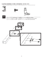 12
12
-
 13
13
-
 14
14
-
 15
15
-
 16
16
-
 17
17
-
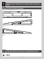 18
18
-
 19
19
-
 20
20
-
 21
21
-
 22
22
-
 23
23
-
 24
24
-
 25
25
-
 26
26
-
 27
27
-
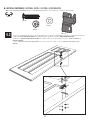 28
28
-
 29
29
-
 30
30
-
 31
31
-
 32
32
-
 33
33
-
 34
34
-
 35
35
-
 36
36
-
 37
37
-
 38
38
-
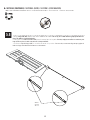 39
39
-
 40
40
-
 41
41
-
 42
42
-
 43
43
-
 44
44
-
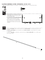 45
45
-
 46
46
-
 47
47
-
 48
48
-
 49
49
-
 50
50
-
 51
51
-
 52
52
-
 53
53
-
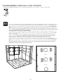 54
54
-
 55
55
-
 56
56
-
 57
57
-
 58
58
-
 59
59
-
 60
60
-
 61
61
-
 62
62
-
 63
63
-
 64
64
-
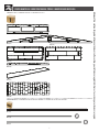 65
65
-
 66
66
-
 67
67
-
 68
68
-
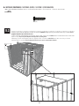 69
69
-
 70
70
-
 71
71
-
 72
72
-
 73
73
-
 74
74
-
 75
75
-
 76
76
-
 77
77
-
 78
78
-
 79
79
-
 80
80
-
 81
81
-
 82
82
-
 83
83
-
 84
84
-
 85
85
-
 86
86
-
 87
87
-
 88
88
-
 89
89
-
 90
90
-
 91
91
-
 92
92
-
 93
93
-
 94
94
-
 95
95
-
 96
96
-
 97
97
-
 98
98
-
 99
99
-
 100
100
-
 101
101
-
 102
102
-
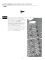 103
103
-
 104
104
-
 105
105
-
 106
106
-
 107
107
-
 108
108
-
 109
109
-
 110
110
-
 111
111
-
 112
112
-
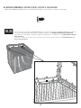 113
113
-
 114
114
-
 115
115
-
 116
116
-
 117
117
-
 118
118
-
 119
119
-
 120
120
-
 121
121
-
 122
122
-
 123
123
-
 124
124
-
 125
125
-
 126
126
-
 127
127
-
 128
128
-
 129
129
-
 130
130
-
 131
131
-
 132
132


en otros idiomas
- français: Lifetime 60336 Le manuel du propriétaire
- English: Lifetime 60336 Owner's manual
Artículos relacionados
-
Lifetime 60300 El manual del propietario
-
Lifetime 60331U El manual del propietario
-
-
-
-
-
-
-
-
Lifetime 60138 El manual del propietario