Kicker 2021 KXMA 8-Channel Amplifier El manual del propietario
- Categoría
- Amplificador de instrumentos musicales
- Tipo
- El manual del propietario
Este manual también es adecuado para

KXMA800.8
Manual del Propietario | Español
AMPLIFICADOR DEL LA SERIE KXM.8
Benutzerhandbuch | Deutsch
VERSTÄRKER DER KXM.8-SERIE
Manuel d’utilisation | Française
AMPLIFICATEUR DE SÉRIE KXM.8
KXM
AMPLIFIERS
Owner’s Manual
2021 KXMA 8-CH Amp Rev C.indd 12021 KXMA 8-CH Amp Rev C.indd 1 10/6/2020 7:10:49 AM10/6/2020 7:10:49 AM

2
KXMA.8 SERIES AMPLIFIERS
OWNER’S MANUAL
INSTALLATION
Mounting: Choose a structurally sound location to mount your KICKER amplifi er. Make sure there are no
items behind the area where the screws will be driven. Choose a location that allows at least 4” (10cm)
of open ventilation for the amplifi er. If possible, mount the amplifi er in the climate-controlled passenger
compartment. Drill four holes using a 7/64” (3mm) bit and use the supplied #8 screws to mount the
amplifi er.
Wiring: The KXMA amplifi er’s RCA inputs will receive either high or low level signals from your car stereo’s
source unit. A high-level signal can be run from the source unit’s speaker outputs to the stereo RCA
input on the end panel of the amplifi er using the KICKER KISL as shown. Alternatively, the signal can be
delivered to the amplifi er using the low-level RCA outputs on the source unit. Keep the audio signal cable
away from factory wiring harnesses and other power wiring. If you need to cross this wiring, cross it at a
90 degree angle.
PERFORMANCE
MODEL: KXMA800.8
IMPORTANT SAFETY WARNING
PROLONGED CONTINUOUS OPERATION OF AN AMPLIFIER, SPEAKER, OR SUBWOOFER
IN A DISTORTED, CLIPPED OR OVER-POWERED MANNER CAN CAUSE YOUR AUDIO
SYSTEM TO OVERHEAT, POSSIBLY CATCHING FIRE AND RESULTING IN SERIOUS
DAMAGE TO YOUR COMPONENTS AND/OR VEHICLE. AMPLIFIERS REQUIRE UP TO 4
INCHES (10CM) OPEN VENTILATION. SUBWOOFERS SHOULD BE MOUNTED WITH AT
LEAST 1 INCH (2.5CM) CLEARANCE BETWEEN THE FRONT OF THE SPEAKER AND ANY
SURFACE.
Model: KXMA800.8
RMS Power
@ 14.4V, 4 stereo, ≤ 1% THD+N
@ 14.4V, 2 stereo, ≤ 1% THD+N
@ 14.4V, 4Ω bridged mono, ≤ 1% THD+N
50 x 8
100 x 8
200 x 4
Length [in, cm] 14-3/4, 37.4
Specifi cations common to all models:
Height [in, cm] 2-1/8, 5.5
Width [in, cm] 8-5/16, 21
Frequency Response [Hz] 10Hz–20kHz
Signal-to-Noise Ratio [dB]
1W Signal-to-Noise Ratio [dB]
95dB
-75dB
Input Sensitivity Low Level: 125mV–5V
High Level: 250mV–10V
Selectable Electronic Crossover AMP1 and AMP2: Off; Variable HP, 10-500Hz; Variable LP
10–500Hz; HP and LP 100–5000Hz with 10X Switch; Slope: 24dB/
octave
AMP3 and AMP4: Off; Variable HP, 10-500Hz; Variable LP
40–500Hz; LP 400Hz–5000Hz with 10X Switch (bandpass capable);
Slope: 24dB/octave
KickEQ™ Bass Boost 0–6dB @ 40Hz
2021 KXMA 8-CH Amp Rev C.indd 22021 KXMA 8-CH Amp Rev C.indd 2 10/6/2020 7:10:57 AM10/6/2020 7:10:57 AM

3
Install a fuse within 7” (18cm) of the battery and in-line with the power cable connected to your amplifi er.
POWER WIRING
source unit
high-level speaker
outputs
to amplifi er
shield
+
–
core conductor
KICKER KISL (optional)
from source unit high-
level speaker outputs
OR
to amplifi er
Model External Fuse
(sold separately)
Power/Ground Wire KICKER Wiring Kit
KXMA800.8 1 x 120 Ampere 4 Gauge KMPK4, PK4, CK4
//
REM +12VGND
POWER
AMP3
AMP4 BRIDGED
L
+
L
-
R
+
R
-
BRIDGED
AMP1
AMP2 BRIDGED
L
+
L
-
R
+
R
-
BRIDGED
AMP1
L
R
AMP2 AMP3 AMP4
AUTO
TURN-ON
12V/DC/AUDIO
AMP2/AMP3
FADER
AMP1/AMP2
FADER
AMP3/AMP4
FADER
ON OFF ON OFF
ON OFF
LO/HI LO/HI
AMP1
AMP2
INPUT
LEVEL
AMP3
AMP4
INPUT
LEVEL
12V
Use the FADER switches to select which inputs are active with
respect to their paired output. ON will activate the second input.
for example:
If you are using a single RCA pair of inputs, set all FADER
switches to OFF.
For any amp section being driven by additional RCA input(s), set
the FADER switch(es) to ON.
If you are using all four RCA pairs of inputs, set all FADER
switches to ON.
battery
external fuse
remote turn-on (see page 6)
≤7”
(18cm)
ABYC-compliant power terminals
Amplifi er uses 304-stainless
steel screws and conformal
coated PCB for increased
weather resistance
aluminum bottom plate
audio inputs
2021 KXMA 8-CH Amp Rev C.indd 32021 KXMA 8-CH Amp Rev C.indd 3 10/6/2020 7:10:58 AM10/6/2020 7:10:58 AM

4
For multiple amplifi er installations where distribution blocks are used, each amplifi er should have its
proper-rated fuse, or breaker, installed between the amplifi er and the distribution block within seven inches
of the block, or on the distribution block if it provides for fusing. The primary power wire should also be
fused between the battery and distribution block, within seven inches of the battery’s B+ terminal, with
a fuse or breaker rated at least to the sum of the individual amplifi er’s fuse values, but not to exceed
1.5-times the sum of the individual fuse values (not to exceed the ampacity of the thermal insulation of the
wiring as shown in U.S.C.G. CFR33 183.425, Table 5). KICKER recommends using the KICKER marine
line of power distribution accessories. These are fully marine compliant with ignition protected fuses and
meet all USCG standards. Pair a KMFMF master fuse holder for your main power with a KMFDB3 and
KMDB3 fused power and ground distribution blocks for the ultimate in protection for your boat! See the
diagram below.
NOTE: Seven inches is the standard distance under U.S. Coast Guard CFR33 for placement of fuses or
breakers as required by law for new boat manufacturing. We recommend trying to adhere to this standard
in a consumer installation. Failure to do so does not mean you are breaking the law, but it does put the
safety of your boat and passengers at risk in the event of a power wire short circuit.
12V
to amplifi er to amplifi er
KMFDB3
Fused Power
Distribution Block
KMDB3
Ground
Distribution Block
battery
KMFMF fuse holder
2021 KXMA 8-CH Amp Rev C.indd 42021 KXMA 8-CH Amp Rev C.indd 4 10/6/2020 7:10:58 AM10/6/2020 7:10:58 AM

5
REM +12VGND
POWER
AMP3
AMP4 BRIDGED
L
+
L
-
R
+
R
-
BRIDGED
AMP1
AMP2 BRIDGED
L
+
L
-
R
+
R
-
BRIDGED
AMP1
L
R
AMP2 AMP3 AMP4
AUTO
TURN-ON
12V/DC/AUDIO
AMP2/AMP3
FADER
AMP1/AMP2
FADER
AMP3/AMP4
FADER
ON OFF ON OFF
ON OFF
//
LO/HI LO/HI
AMP1
AMP2
INPUT
LEVEL
AMP3
AMP4
INPUT
LEVEL
REM +12VGND
POWER
AMP3
AMP4 BRIDGED
L
+
L
-
R
+
R
-
BRIDGED
AMP1
AMP2 BRIDGED
L
+
L
-
R
+
R
-
BRIDGED
AMP1
L
R
AMP2 AMP3 AMP4
AUTO
TURN-ON
12V/DC/AUDIO
AMP2/AMP3
FADER
AMP1/AMP2
FADER
AMP3/AMP4
FADER
ON OFF ON OFF
ON OFF
//
LO/HI LO/HI
AMP1
AMP2
INPUT
LEVEL
AMP3
AMP4
INPUT
LEVEL
BRIDGED OPERATION
minimum impedance of 4 ohms
EIGHT CHANNEL OPERATION
minimum impedance of 2 ohm
2021 KXMA 8-CH Amp Rev C.indd 52021 KXMA 8-CH Amp Rev C.indd 5 10/6/2020 7:10:59 AM10/6/2020 7:10:59 AM

6
OPERATION
Automatic Turn-On Selection: The KXMA series offers three different automatic turn-on modes that
can be selected on the end panel; +12V, DC Offset, and Audio. Using either the DC Offset or Audio
mode causes the REM terminal to have +12V out for turning on additional amplifi ers.
• Remote Turn-On: Set the switch to +12V to use the remote turn-on lead from your source unit.
Run 18 gauge wire from the Remote Turn-On Lead on your source unit to the terminal labeled REM
between the amplifi er’s positive and negative power terminals. This is the preferred automatic turn-on
method.
• DC Offset Turn-On: If Remote Turn-On is not an option, the next best setting is DC Offset. The DC
Offset mode detects a 3V DC offset from the HI-Level speaker outputs when the source unit has
been turned on.
• Signal Sense Turn-On: The Audio setting is the fi nal alternative for Automatic turn-on. This is a
Signal Sense turn-on method that detects the incoming audio signal from your source unit and
automatically turns on the amp. This turn-on method will not work properly if the input gain control is
not set appropriately.
Fader Switches: Turn the Fader switch(es) OFF if you are running more than a single pair of RCA inputs
to the amplifi er. Turn the Fader switch(es) ON if you want to drive those channels from a single input. For
example, if you are using AMP 1, AMP 2, AMP 3, and AMP 4 RCA inputs, switch the AMP 1/AMP 2
FADER, AMP 2/AMP 3 FADER , and AMP 3/AMP 4 FADER buttons to ON.
Input Gain Control with Gain Matching: The input gain control is not a volume control. It matches the
output of the source unit to the input level of the amplifi er and features Gain Matching to prevent clipping
the input. For a quick setup, turn the source unit up to about 3/4 volume (if the source unit goes to 30,
turn it to 25). KICKER recommends using the test tones at www.kicker.com/support/ to reach the most
accurate and best performing settings. Next, slowly turn (clockwise) the gain on the amplifi er up until you
see the Gain LED light up or hear audible distortion, then turn it down a little. If the GAIN knob’s backlight
comes on, the input is still clipping. For full instructions on Gain Matching, please see the next page.
Crossover Switches with Frequency Multiplier: Use the XOVER switches on the end panel of
the amplifi er to set the internal crossovers of AMPS 1 & 2 to OFF, HI-PASS, or LO-PASS, and the
crossovers of AMPS 3 & 4 to OFF, HI-PASS, LO-PASS, or BAND-PASS. When the switch is set
to OFF, a full bandwidth signal will be amplifi ed. Set the switch to HP if you want the amplifi er’s internal
crossover to serve as a high-pass fi lter. Set the switch to LP if you want the amplifi er’s internal crossover
to serve as a low-pass fi lter. Set the switch to BP when a specifi c frequency range is required. Never
change the crossover switches with the audio system on!
Set the 1X/10X frequency multiplier switch to the setting that is appropriate for your application. A
setting of 10X will set the range of the AMP 1 & AMP 2 crossovers to 100–5,000Hz, and the low pass
crossovers of AMP 3 & AMP 4 to 100–5,000Hz.
KICK EQ Bass Boost Control: The variable bass boost controls on the side of the KXMA800.8
amplifi er are designed to give you increased output, 0–6dB, at 40Hz. The setting for this control is
Mini-USB for internal use only; do NOT remove or tamper. KICKER is not responsible for any damage to
equipment resulting from connections made to this port.
KXMA800.8
PRT
GAIN
110
X-OVER X-OVER X-OVER X-OVER
OFF/HP/LP OFF/HP/LP
OFF/HP/LP/BP OFF/HP/LP/BP
50010
HI-PASS
Hz
50040
LO-PASS
Hz 50010
HI-PASS
Hz 50040
LO-PASS
Hz60
KICK EQ
dB 60
KICK EQ
dB 60
KICK EQ
dB
1X/10X
LO-PASS
RANGE
1X/10X
LO-PASS
RANGE
1X/10X
RANGE
1X/10X
RANGE
50010
FREQ.
Hz 50010
FREQ.
Hz
AMP1 AMP2 AMP3 AMP4
GAIN
110
GAIN
110
60
KICK EQ
dB
GAIN
110
GAIN
MATCH
GAIN
MATCH
GAIN
MATCH
GAIN
MATCH
2021 KXMA 8-CH Amp Rev C.indd 62021 KXMA 8-CH Amp Rev C.indd 6 10/6/2020 7:10:59 AM10/6/2020 7:10:59 AM

7
GAIN MATCHING
In any audio system, the goal is to reach maximum input and output levels without distortion or clipping.
The engineers at KICKER have taken the guesswork, and hassle, out of matching the output voltage of
your source unit to the amplifi er with the Gain Matching feature. To begin, you’ll need to download the
KICKER test tones from www.kicker.com/test-tones. The following fi les are available in MP3 and WAV
formats:
1kHz @ 0dBFS, 50Hz @ 0dBFS, 1kHz @ -10dBFS, 50Hz @ -10dBFS, 1kHz @ -5dBFS, 50Hz @ -5dBFS
These test tones are sine waves meant to provide a consistent signal for the KXMA amplifi er to reference.
The different recording levels are designed to give you the perfect gain match for your application.
0dBFS: Designed for audiophile applications to give you distortion free audio output with the most
dynamic range.
-5dBFS: Designed for normal/daily applications, there will be less dynamic range but higher potential
audio output levels. With this set up you can get some occasional clipping from the amplifi er.
-10dBFS: Designed only for Subwoofer applications, there will be less dynamic range but higher potential
audio output levels. With this set up you can get some clipping from the amplifi er.
Afterwards, use the following procedure to accurately Gain Match your amplifi er(s):
1. Disconnect the speakers from the KXMA amplifi er.
2. Set all EQ and crossover settings to fl at on your source unit.
3. Play the downloadable fi le from KICKER.com
4. Turn the source unit up to 3/4 volume.
5. Increase the gain of the amplifi er until the Gain LED turns on.
6. Decrease the gain of the amplifi er until the Gain LED turns off.
All level matching circuitry in the KXMA amplifi ers is at the beginning of the signal chain. If you are going
to use features like bass boost, SHOCwave or EQ settings, it may be necessary to readjust the gain to a
lower setting to compensate for increased output at those frequencies.
Once the amp and source unit are gain matched, you will want to make certain you are not overdriving
your speakers. Use the following procedure:
1. Set the source until volume to 0.
2. Reconnect the speakers to the KXMA amplifi er.
3. Slowly increase the volume level of the source unit as you listen for audible distortion.
4. If you can hear clipping, decrease the gain of the amplifi er until it is gone.
GAIN
MATCH
subjective. If you turn it up, you must readjust the input gain control to avoid clipping the amplifi er.
2021 KXMA 8-CH Amp Rev C.indd 72021 KXMA 8-CH Amp Rev C.indd 7 10/6/2020 7:11:00 AM10/6/2020 7:11:00 AM

8
TROUBLESHOOTING
If your amplifi er does not appear to be working, check the obvious things fi rst such as blown fuses, poor
or incorrect wiring connections, incorrect setting of crossover switch and gain controls, etc. There is a
Protection (PRT) LED on the side panel of your Kicker KXMA series amplifi er. Depending on the state of
the amplifi er and the vehicle’s charging system, the LED will either glow red or be off.
Red (PRT) LED fl ickering with loud music? The red (PRT) LED indicates low battery voltage. Check
all the connections in your vehicle’s charging system. It may be necessary to replace or charge your
vehicle’s battery or replace your vehicle’s alternator.
Red (PRT) LED on, no output?
Amplifi er is very hot = thermal protection is engaged. Test for proper
impedance at the speaker terminals with a VOM meter (see the diagrams in this manual for minimum
recommended impedance and multiple speaker wiring suggestions). Also check for adequate airfl ow
around the amplifi er.
Amplifi er shuts down only while vehicle is running = voltage protection circuitry is
engaged. Voltage to the amplifi er is not within the 10–16 volt operating range. Have the vehicle’s charging
and electrical system inspected.
Amplifi er will only play at low volume levels = short circuit protection
is engaged. Check for speaker wires shorted to each other or to the vehicle chassis. Check for damaged
speakers or speaker(s) operating below the minimum recommended impedance.
No or low output?
Check the balance control on source unit
Check the RCA (or speaker input)
and speaker output connections.
Alternator noise-whining sound with engine’s RPM?
Check for damaged RCA (or speaker
input) cable
Check the routing of RCA (or speaker input) cable
Check the source unit for proper
grounding
Check the gain settings and turn them down if they are set too high.
Ground Noise? KICKER amplifi ers are engineered to be fully compatible with all manufacturers’ head
units. Some head units may require additional grounding to prevent noise from entering the audio signal. If
you are experiencing this problem with your head unit, in most cases running a ground wire from the RCA
outputs on the head unit to the chassis will remedy this issue.
CAUTION: When jump starting the vehicle, be sure that connections made with jumper cables are
correct. Improper connections can result in blown amplifi er fuses as well as the failure of other critical
systems in the vehicle.
If you have more questions about the installation or operation of your new KICKER product, see the
Authorized KICKER Dealer where you made your purchase. For more advice on installation, click on the
SUPPORT tab on the KICKER homepage, www.kicker.com. Choose the TECHNICAL SUPPORT tab,
choose the subject you are interested in, and then download or view the corresponding information.
Please E-mail support@kicker.com or call Technical Services (405) 624-8583 for unanswered or specifi c
questions.
KICKER will now provide a three-year warranty with all KXMA-Series
Amplifi er purchases paired with a qualifying KICKER Installation Kit* .
This extends the standard warranty by an additional year. Amplifi er and Kit must be
purchased from an Authorized KICKER Dealer.
KICKER KXMA amplifi er success is currently at an unheard-of rate, making the extended
warranty program even more benefi cial to you.
Using poor-quality, under-spec wiring kits will impede KXMA amplifi er performance.
A superior-quality KICKER installation Kit is guaranteed to extend the life of KXMA
amplifi ers.
The new extended warranty applies only to KICKER amplifi ers and accessories sold to consumers by Authorized
KICKER Dealers in the United States of America or its possessions. It also only applies to the original purchaser of
KICKER amplifi ers and accessories. One warranty extension per amplifi er is allowed regardless of the number of amplifi er
installation kits purchased. This program does not apply to “B”-stock product or factory-refurbished product.
This offer is for a limited time, so see your local Authorized KICKER Dealer soon for details.
*U.S.A. Only | EE.UU. solamente | Nur USA | Les USA Seulement
2021 KXMA 8-CH Amp Rev C.indd 82021 KXMA 8-CH Amp Rev C.indd 8 10/6/2020 7:11:00 AM10/6/2020 7:11:00 AM

9
Modelo:
KXMA800.8
Potencia RMS [Vatios]
a 14.4V, 4 stereo, ≤ 1% THD+N
a 14.4V, 2 stereo, ≤ 1% THD+N
a 14.4V, 4Ω mono, ≤ 1% THD+N
50 x 8
100 x 8
200 x 4
Longitud [pulg, cm] 14-3/4, 37.4
Especifi caciones en común de todos los modelos:
Altura [pulg, cm] 2-1/8, 5.5
Ancho [pulg, cm] 8-5/16, 21
Respuesta de frecuencia ± 1dB 10Hz–20kHz
Relación señal-ruido [dB]
1W Relación señal-ruido [dB]
>95dB, ponderación A, re: potencia nominal
-75dB
Sensibilidad de entrada Bajo nivel: 125mV–5V
Alto nivel: 250mV–10V
Divisor de frecuencias electrónico seleccionable AMP1 and AMP2: Off; Variable HP, 10-500Hz; Variable
LP 10–500Hz; HP and LP 100–5000Hz con interruptor
10X; Slope: 24dB/octave
AMP3 and AMP4: Off; Variable HP, 10-500Hz; Variable
LP 40–500Hz; LP 400Hz–5000Hz con interruptor 10X
Switch (bp capaces); Slope: 24dB/octave
Refuerzo de graves KickEQ
™
0–6dB @ 40Hz
AMPLIFICADOR DE LA SERIE KXMA.8
MANUAL DEL PROPIETARIO
INSTALACIÓN
Montaje: Escoja un lugar estructuralmente sólido para montar el amplifi cador KICKER. Asegúrese de
que no haya nada por detrás de dónde van a entrar los tornillos. Escoja un lugar en que queden por lo
menos 4 plg. (10 cm) de espacio abierto de ventilación alrededor del amplifi cador. Si es posible, monte el
amplifi cador en el compartimiento de pasajeros, con ambiente acondicionado. Haga cuatro agujeros con
una broca de 7/64 de plg. (3 mm) y monte el amplifi cador con los tornillos N° 8 que se suministran.
Cableado: Las entradas RCA del amplifi cador KXMA recibirán señales de alto o bajo nivel desde la unidad
fuente del estéreo de su automóvil. Una señal de alto nivel se puede transmitir desde las salidas de los
altavoces de la unidad fuente hasta la entrada RCA del estéreo en el panel inferior del amplifi cador utilizando
el KICKER KISL, como se muestra en la imagen. Alternativamente, la señal se puede transmitir hacia el
amplifi cador utilizando las salidas RCA de bajo nivel en la unidad fuente. Mantenga el cable de señal de
audio lejos de los arneses de cableado de fábrica y de otros cables eléctricos. Si necesita cruzar este
cableado, hágalo a un ángulo de 90 grados.
RENDIMIENTO
MODELOS: KXMA800.8
ADVERTENCIA IMPORTANTE DE SEGURIDAD: LA OPERACIÓN PROLONGADA Y CONTINUA DE UN
AMPLIFICADOR DE MANERA DISTORSIONADA O CORTADA PUEDE PROVOCAR QUE SU SISTEMA DE
AUDIO SE SOBRECALIENTE CON LA POSIBILIDAD DE INCENDIARSE Y PROVOCAR DAÑOS GRAVES A SUS
COMPONENTES O VEHÍCULO. ¡LOS PRODUCTOS KICKER PUEDEN PRODUCIR NIVELES DE SONIDO QUE
PUEDEN DAÑAR PERMANENTEMENTE SU OÍDO! SUBIR EL VOLUMEN DE UN SISTEMA A UN NIVEL EN EL
CUAL SE ESCUCHA UNA DISTORSIÓN ES MÁS DAÑINO PARA SUS OÍDOS QUE ESCUCHAR UN SISTEMA SIN
DISTORSIÓN AL MISMO NIVEL DE VOLUMEN. EL UMBRAL DEL DOLOR ES SIEMPRE UN INDICADOR DE QUE
EL NIVEL DEL SONIDO ES MUY ALTO Y PUEDE DAÑAR PERMANENTEMENTE SU AUDICIÓN. USE EL SENTIDO
COMÚN AL CONTROLAR EL VOLUMEN.
2021 KXMA 8-CH Amp Rev C.indd 92021 KXMA 8-CH Amp Rev C.indd 9 10/6/2020 7:11:01 AM10/6/2020 7:11:01 AM

10
//
REM +12VGND
POWER
AMP3
AMP4 BRIDGED
L
+
L
-
R
+
R
-
BRIDGED
AMP1
AMP2 BRIDGED
L
+
L
-
R
+
R
-
BRIDGED
AMP1
L
R
AMP2 AMP3 AMP4
AUTO
TURN-ON
12V/DC/AUDIO
AMP2/AMP3
FADER
AMP1/AMP2
FADER
AMP3/AMP4
FADER
ON OFF ON OFF
ON OFF
LO/HI LO/HI
AMP1
AMP2
INPUT
LEVEL
AMP3
AMP4
INPUT
LEVEL
12V
batería
fusible externo
encendido a distancia (página 13)
≤7”
(18cm)
Modelo Fusible Externo
(no incluido)
Cable de Alimentación y
Conexión a Tierra
Kit de cableado
KICKER
KXMA800.8 1 x 120 Ampere Calibre 4 KMPK4, PK4, CK4
Cable de salida
de altavoz de
alto nivel
Hacia el amplifi cador
Hacia el
amplifi cador
Conexión a tierra o blindaje
+
–
cable central
Instale un fusible a menos de 7 plg. (18 cm) de la batería y en línea con el cable de alimentación
conectado al amplifi cador.
KICKER KISL
Cable de salida de
altavoz de alto nivel
O
CABLEADO DE ALIMENTACIÓN
Placa con fondo
de aluminio
El amplifi cador utiliza tornillos
de acero inoxidable tipo 304 y
placa de circuito impreso con
recubrimiento conformado para
una mayor resistencia al clima.
Terminales de energía
aprobados por ABYC
Use los interruptores del ATENUADOR para seleccionar
las entradas que estarán activas con respecto a su salida
sincronizada. El modo ACTIVADO activará la segunda entrada.
Por ejemplo:
Si usa un solo par de entradas de RCA, coloque todos los
interruptores del ATENUADOR en posición DESACTIVADO.
Para toda sección del amplifi cador que esté impulsada por
entradas de RCA adicionales, coloque los interruptores del
ATENUADOR en posición ACTIVADO.
Si usa los cuatro pares de entradas de RCA, coloque todos los
interruptores del ATENUADOR en posición ACTIVADO.
2021 KXMA 8-CH Amp Rev C.indd 102021 KXMA 8-CH Amp Rev C.indd 10 10/6/2020 7:11:01 AM10/6/2020 7:11:01 AM

11
Para varias instalaciones de amplifi cadores donde se utilizan bloques de distribución, cada amplifi cador
debe poseer su fusible de grado apropiado, o interruptor, instalado entre el amplifi cador y el bloque de
distribución a siete pulgadas del bloque, o sobre el bloque de distribución si admite fusibles. El principal
cable de alimentación también debe fusionarse entre la batería y el bloque de distribución, a siete
pulgadas del terminal B+ de la batería, con un fusible o interruptor con una clasifi cación al menos de la
suma de los valores individuales del fusible del amplifi cador, pero que no supere 1,5 veces la suma de
los valores individuales del fusible (que no supere la ampacidad del aislamiento térmico del cableado
como se demuestra en U.S.C.G. CFR33 183.425, Tabla 5). Vea el siguiente diagrama.
NOTA: Siete pulgadas es la distancia estándar según la Guardia Costera de los Estados Unidos, CFR33,
para la colocación de fusibles o interruptores como lo requiere la ley para la fabricación de nuevos
barcos. Recomendamos cumplir con este estándar en caso de ser instalado por el consumidor. El no
hacerlo no signifi ca que no cumple con la ley, pero pone en riesgo la seguridad de su barco y de los
pasajeros en caso de cortocircuito eléctrico.
12V
Hacia el
amplifi cador
Hacia el
amplifi cador
KMFMF
portafusibles
KMFDB3
Bloqueo de distribución
de energía
KMDB3
Bloqueo de
distribución de tierra
batería
2021 KXMA 8-CH Amp Rev C.indd 112021 KXMA 8-CH Amp Rev C.indd 11 10/6/2020 7:11:02 AM10/6/2020 7:11:02 AM

12
REM +12VGND
POWER
AMP3
AMP4 BRIDGED
L
+
L
-
R
+
R
-
BRIDGED
AMP1
AMP2 BRIDGED
L
+
L
-
R
+
R
-
BRIDGED
AMP1
L
R
AMP2 AMP3 AMP4
AUTO
TURN-ON
12V/DC/AUDIO
AMP2/AMP3
FADER
AMP1/AMP2
FADER
AMP3/AMP4
FADER
ON OFF ON OFF
ON OFF
//
LO/HI LO/HI
AMP1
AMP2
INPUT
LEVEL
AMP3
AMP4
INPUT
LEVEL
REM +12VGND
POWER
AMP3
AMP4 BRIDGED
L
+
L
-
R
+
R
-
BRIDGED
AMP1
AMP2 BRIDGED
L
+
L
-
R
+
R
-
BRIDGED
AMP1
L
R
AMP2 AMP3 AMP4
AUTO
TURN-ON
12V/DC/AUDIO
AMP2/AMP3
FADER
AMP1/AMP2
FADER
AMP3/AMP4
FADER
ON OFF ON OFF
ON OFF
//
LO/HI LO/HI
AMP1
AMP2
INPUT
LEVEL
AMP3
AMP4
INPUT
LEVEL
FUNCIONAMIENTO EN PUENTE
impedancia mínima de 4 ohmios en puente
FUNCIONAMIENTO POR OCHO CANALES (ESTEREOFÓNICO)
impedancia mínima de 2 ohmio por canal en estereofónico
2021 KXMA 8-CH Amp Rev C.indd 122021 KXMA 8-CH Amp Rev C.indd 12 10/6/2020 7:11:02 AM10/6/2020 7:11:02 AM

13
Selección de Encendido Automático: La serie KXMA ofrece dos modalidades de encendido
automático que: +12V, y compensación de CC.
• Encendido a Distancia: Instale cable calibre 18 desde el conductor de encendido a distancia de la
unidad fuente hasta la terminal etiquetada REM entre las terminales de alimentación positiva y negativa
del amplifi cador.
• Encendido por Compensación de CC: En la modalidad de compensación de CC, el amplifi cador
detecta una subida de 3V de las salidas de altavoz de alto nivel cuando la unidad fuente se ha
encendido.
• Encendido por Detección de Señal: La modalidad de es la opción fi nal de encendido automático. Este
es un método de encendido en que el amplifi cador detecta la señal de audio procedente de la unidad
fuente y se enciende automáticamente. Este método de encendido no funciona correctamente si el
control de amplifi cación de entrada no se ha fi jado correctamente.
Interruptor del atenuador: Deprima el interruptor del atenuador si está operando dos juegos de
entrada (delantero y trasero por ejemplo) al amplifi cador. Deje el interruptor del atenuador apagado si
desea manejar todos los canales desde una única entrada estéreo.
Interruptores de transición con multiplicador de frecuencia: Use los interruptores XOVER en el
panel fi nal del amplifi cador para ajustar las transiciones internas de AMPS 1 y 2 a APAGADO, PASO ALTO,
o PASO BAJO, y AMPS 3 y 4 a APAGADO, PASO ALTO, PASO BAJO, o PASO DE BANDA. Cuando el
interruptor se ajusta a APAGADO, se amplifi cará una señal completa de banda ancha. Ajuste el interruptor a
HP si desea que la transición interna del amplifi cador sirva como un fi ltro de paso alto. Ajuste el interruptor
a LP si desea que la transición interna del amplifi cador sirva como un fi ltro de paso bajo. Ajuste este
interruptor a BP cuando requiera un rango de frecuencia específi co. ¡Nunca cambie los interruptores de
transición cuando esté encendido el sistema de audio!
Ajuste el interruptor del multiplicador de frecuencia 1X/10X a la selección que sea apropiada para su
aplicación. Un ajuste de 10X seleccionará el rango de transición a 100–5,000Hz para AMPS 1 y 2, y la
transición PASO BAJO a 400–5,000Hz para AMPS 3 y 4.
Control de ganancia de entrada con Sincronización de ganancia: El control de ganancia de
entrada no es un control de volumen. Sincroniza la salida de la unidad fuente con el nivel de entrada del
amplifi cador, y cuenta con Sincronización de ganancia para evitar recortes de la entrada. Para realizar una
confi guración rápida, suba el volumen de la unidad fuente hasta aproximadamente 3/4 (si la unidad fuente
llega a 30, súbala a 25). Luego, suba lentamente (hacia la derecha) la ganancia en el amplifi cador hasta que
se encienda la luz LED de ganancia o hasta que escuche una distorsión, luego bájela un poco. KICKER
recomienda que se usen los tonos de prueba en www.kicker.com/support/ para alcanzar los ajustes más
exactos y de mejor desempeño. Si se enciende la luz de fondo de la perilla GAIN (Ganancia), signifi ca
que aún hay recorte en la entrada. Lea la siguiente página para obtener todas las instrucciones sobre la
Sincronización de ganancia.
Refuerzo de Bajos: El control variable de refuerzo de bajos ubicado en el panel de extremo del
amplifi cador ha sido diseñado para dar una mayor salida de bajos, de 0 a dB a 40 Hz. La confi guración
de este control es subjetiva. Si usted lo sube, debe volver a ajustar el control de amplifi cación para evitar la
limitación de la señal del amplifi cador.
FUNCIONAMIENTO
KXMA800.8
PRT
GAIN
110
X-OVER X-OVER X-OVER X-OVER
OFF/HP/LP OFF/HP/LP
OFF/HP/LP/BP OFF/HP/LP/BP
50010
HI-PASS
Hz
50040
LO-PASS
Hz 50010
HI-PASS
Hz 50040
LO-PASS
Hz60
KICK EQ
dB 60
KICK EQ
dB 60
KICK EQ
dB
1X/10X
LO-PASS
RANGE
1X/10X
LO-PASS
RANGE
1X/10X
RANGE
1X/10X
RANGE
50010
FREQ.
Hz 50010
FREQ.
Hz
AMP1 AMP2 AMP3 AMP4
GAIN
110
GAIN
110
60
KICK EQ
dB
GAIN
110
GAIN
MATCH
GAIN
MATCH
GAIN
MATCH
GAIN
MATCH
2021 KXMA 8-CH Amp Rev C.indd 132021 KXMA 8-CH Amp Rev C.indd 13 10/6/2020 7:11:03 AM10/6/2020 7:11:03 AM

14
SINCRONIZACIÓN DE GANANCIA
En un sistema de audio, el objetivo es lograr los niveles máximos de entrada y salida sin distorsión ni
recortes. Con la función “Sincronización de ganancia”, los ingenieros de KICKER lograron que no sea
necesario hacer conjeturas ni complicarse a la hora de sincronizar el voltaje de salida de su unidad de
alimentación con el amplifi cador. Para comenzar, deberá descargar los tonos de prueba de KICKER
desde www.kicker.com/test-tones Los siguientes archivos están disponibles en formato MP3 y WAV:
1 kHz a 0 dBFS, 50 Hz a 0 dBFS, 1 kHz a -10 dBFS, 50 Hz a -10 dBFS, 1 kHz a -5 dBFS, 50 Hz a -5
dBFS
Estos tonos de prueba son ondas senoidales que tienen como fi n ofrecer una señal uniforme para que
el amplifi cador KXMA pueda tener como referencia. Los diferentes niveles de grabación están diseñados
para darle una sincronización de ganancia perfecta para su aplicación.
0 dBFS: Diseñado para aplicaciones de afi cionados a la música, para ofrecerle una salida de audio sin
distorsiones con el rango más dinámico.
-5 dBFS: Diseñado para aplicaciones normales/diarias, ofrece menos rango dinámico, pero niveles
de salida de audio potencialmente más altos. Con esta confi guración, puede haber algunos recortes
ocasionales desde el amplifi cador.
-10 dBFS: Diseñado únicamente para aplicaciones de subwoofers, ofrece menos rango dinámico, pero
niveles de salida de audio potencialmente más altos. Con esta confi guración, puede haber algunos
recortes desde el amplifi cador.
A continuación, siga este procedimiento para Sincronizar ganancia en forma precisa en sus
amplifi cadores:
1. Desconecte los altavoces del amplifi cador KXMA.
2. Coloque todos los ajustes del ecualizador y del divisor de frecuencias en plano en su
unidad de alimentación.
3. Reproduzca el archivo descargado desde KICKER.com.
4. Suba el volumen de la unidad de alimentación a 3/4 de su capacidad.
5. Aumente la ganancia del amplifi cador hasta que se encienda la luz LED de ganancia.
6. Disminuya la ganancia del amplifi cador hasta que se apague la luz LED de ganancia.
Todos los circuitos de sincronización de nivel de los amplifi cadores KXMA están al inicio de la cadena
de señal. Si va a utilizar funciones como el potencializador de graves, SHOCwave o confi guraciones del
ecualizador, es posible que necesite reajustar la ganancia a una confi guración inferior para compensar
una mayor salida en esas frecuencias.
Cuando el amplifi cador y la unidad de alimentación tienen la ganancia sincronizada, debería asegurarse
de no usar los altavoces excesivamente. Use el siguiente procedimiento:
1. Establezca el volumen de la unidad de alimentación en 0.
2. Vuelva a conectar los altavoces al amplifi cador KXMA.
3. Aumente en forma lenta el nivel de volumen de la unidad de alimentación a medida que escucha para
detectar si hay distorsión.
4. Si oye recortes, disminuya la ganancia del amplifi cador hasta que hayan desaparecido.
De la misma forma, puede utilizar la función del indicador CLIP del control remoto CXARC para identifi car
con facilidad cuál es el amplifi cador cuya salida tiene recortes, y en qué momento los tiene.
GAIN
MATCH
2021 KXMA 8-CH Amp Rev C.indd 142021 KXMA 8-CH Amp Rev C.indd 14 10/6/2020 7:11:03 AM10/6/2020 7:11:03 AM

15
RESOLUCIÓN DE PROBLEMAS
Si su amplifi cador parece no estar funcionando, revise lo obvio primero: fusibles quemados, conexiones malas o incorrectas,
posición incorrecta de los selectores de crossover y amplifi cación, etc. Su amplifi cador modelo KXMA de KICKER cuenta
con los LED de protección (PRT) y de encendido (PWR) en el panel de alimentación lateral. Dependiendo del estado del
amplifi cador y del sistema de carga del vehículo, los LED se iluminarán en verde o en rojo. Cuando el LED se ilumina en verde,
indica que el amplifi cador está encendido y no hay ningún problema.
¿El indicador luminoso LED verde está apagado y no hay salida? Con un voltímetro/ohmímetro (VOM), verifi que
lo siguiente:
Hay +12V en la terminal de alimentación (debe leerse entre +12V y +16V).
Hay +12V en la terminal de
encendido a distancia (debe leerse entre +12V y +16V).
No hay conexiones invertidas de alimentación o conexión a tierra.
La terminal de conexión a tierra tiene la conductividad adecuada.
No hay fusibles quemados.
¿El Indicador luminoso LED verde está encendido y no hay salida? Verifi que lo siguiente:
Las conexiones RCA
están bien.
Las salidas de altavoces están bien pues han sido puestas a prueba con un altavoz en buenas condiciones.
Se ha cambiado la unidad fuente por una unidad fuente en buenas condiciones.
Con un medidor VOM confi gurado para
medir voltaje de “CA”, se ha buscado una señal en el cable RCA que alimenta el amplifi cador.
¿El indicador luminoso LED de “protection” destella con la música fuerte? El indicador luminoso LED rojo indica
que hay bajo voltaje de batería. Revise todas las conexiones del sistema de carga eléctrica del vehículo. Puede ser necesario
cambiar o cargar la batería del vehículo o cambiar el alternador del vehículo.
¿El indicador luminoso LED de “protection” está encendido y no hay salida?
El amplifi cador está muy caliente
= Se ha activado el circuito de protección térmica. Con un medidor VOM, compruebe que las terminales de altavoz tengan
la impedancia correcta (vea en este manual los diagramas que contienen datos de impedancia mínima recomendada y
sugerencias de cableado de varios altavoces). Asegúrese también de que haya un fl ujo de aire adecuado alrededor del
amplifi cador.
El amplifi cador se apaga sólo cuando el vehículo está en marcha = Se ha activado el circuito de protección
contra sobrevoltaje. El voltaje al amplifi cador no está dentro del intervalo de funcionamiento de 10V a 16V. Haga inspeccionar
el sistema eléctrico y de carga eléctrica del automóvil.
El amplifi cador sólo funciona a bajo volumen = Se ha activado el
circuito de protección contra cortocircuitos. Asegúrese de que los cables de los altavoces no estén en cortocircuito entre sí o
con el chasis del vehículo. Vea si hay altavoces dañados o funcionando a menos de la impedancia mínima recomendada.
¿No hay salida de uno de los canales?
Revise el control de balance de la unidad fuente.
Revise las conexiones RCA
(o de entrada de altavoz) y de salida de altavoz del canal.
¿Hay ruido sibilante de alternador asociado a las RPM del motor?
Vea si hay algún cable RCA (o de entrada
de altavoz) dañado.
Revise el encaminamiento del cable RCA (o de entrada de altavoz).
Vea si la unidad fuente tiene
conexión a tierra apropiada.
Revise las confi guraciones de amplifi cación y bájelas si están muy altas.
¿Hay baja respuesta de bajos? Invierta la conexión de uno de los altavoces de positiva a negativa en los canales
estereofónicos y/o de subwoofer; si los bajos mejoran, el altavoz estaba fuera de fase.
¿Hay ruido de conexión a tierra? Los amplifi cadores KICKER son totalmente compatibles con las unidades fuente de
todos los fabricantes. Algunas unidades principales pueden necesitar más conexión a tierra para evitar que entre ruido a la
señal de audio. En la mayoría de los casos, este problema con la unidad principal se resuelve instalando un cable de conexión
a tierra desde las salidas RCA de la unidad principal al chasis.
PRECAUCIÓN: Cuando haga arrancar el vehículo con cables de arranque conectados a una batería externa, asegúrese de
que las conexiones de los cables de arranque sean correctas. Conectar los cables de arranque de manera incorrecta puede
quemar los fusibles del amplifi cador y causar fallas en otros sistemas del vehículo.
Si tiene más preguntas sobre la instalación de su nuevo producto KICKER, vaya al distribuidor autorizado de KICKER donde
lo compró. Si necesita más consejos sobre la instalación, haga clic en la lengüeta SUPPORT (apoyo) de la página Web de
KICKER, www.KICKER.com. Escoja la lengüeta TECHNICAL SUPPORT (apoyo técnico), escoja el tema que le interese
y luego descargue o vea la información correspondiente. Envíe un mensaje por correo electrónico a [email protected]
o comuníquese con Servicios Técnicos llamando al (405) 624-8583 si tiene preguntas específi cas o a las cuales no haya
encontrado respuesta.
2021 KXMA 8-CH Amp Rev C.indd 152021 KXMA 8-CH Amp Rev C.indd 15 10/6/2020 7:11:03 AM10/6/2020 7:11:03 AM

16
Modèle:
KXMA800.8
Puissance RMS, Watts
@ 14.4V, 4 stereo, ≤ 1% THD+N
@ 14.4V, 2 stereo, ≤ 1% THD+N
@ 14.4V, 4Ω ponte mono, ≤ 1% THD+N
50 x 8
100 x 8
200 x 4
Longueur [po, cm] 14-3/4, 37,4
Caractéristiques communes à tous les modèles :
Hauteur [po, cm] 2-1/8, 5,5
Largeur [po, cm] 8-5/16, 21
Réponse en fréquence [Hz] 10Hz–20kHz
Rapport signal-bruit [dB]
1W Rapport signal-bruit [dB]
>95dB
-75dB
Sensibilité d’Entrée Niveau bas : 125 mV–5 V
Niveau élevé : 250mV-10V
Crossover électronique sélectionnable AMP1 and AMP2: Off; Variable HP, 10-500Hz; Variable LP 10–
500Hz; HP and LP 100–5000Hz avec commutateur multiplicateur
par 10; Slope: 24dB/octave
AMP3 and AMP4: Off; Variable HP, 10-500Hz; Variable LP
40–500Hz; LP 400Hz–5000Hz avec commutateur multiplicateur
par 10 (passe-bande capable); Slope: 24dB/octave
Amplifi cation des graves KickEQ™ 0–6dB @ 40Hz
AMPLIFICATEUR SÉRIE KXMA.8
MANUEL D’UTILISATION
INSTALLATION
Montage: Choisissez un emplacement de structure saine pour monter votre amplifi cateur KICKER.
Assurez-vous que l’arrière de l’emplacement où vous allez enfoncer les vis ne comporte aucun élément.
Choisissez un endroit assurant au moins 10 cm (4 po) de dégagement de ventilation ouverte pour
l’amplifi cateur. Si possible, montez l’amplifi cateur dans l’habitacle passager climatisé. Percez quatre trous
à l’aide d’un foret de 3 mm (7/64 po) et utilisez les vis nº 8 fournies pour monter l’amplifi cateur.
Câblage: Les entrées RCA de l’amplifi cateur KXMA recevront des signaux haut ou bas niveau en
provenance d’autoradio de votre voiture. Il est possible de connecter les sorties des haut-parleurs de
l’autoradio à l’entrée stéréo RCA sur le panneau latéral de l’amplifi cateur à l’aide du câble KICKER KISL,
comme illustré. Une autre option consiste à connecter le signal à l’amplifi cateur en utilisant les sorties
RCA de bas niveau sur l’autoradio. Gardez le câble du signal audio à distance du faisceau de câblage en
usine et des autres câbles d’alimentation. Si vous avez besoin de couper ce câblage, faites-le à un angle
de 90 degrés.
PERFORMANCES
MODÈLE: KXMA800.8
AVERTISSEMENT DE SÉCURITÉ IMPORTANT: UN FONCTIONNEMENT CONTINU ET
PROLONGÉ D’UN AMPLIFICATEUR EN DISTORSION OU EN SATURATION PEUT PROVOQUER
LA SURCHAUFFE DE VOTRE SYSTÈME AUDIO, UN POTENTIEL DÉPART D’INCENDIE ET
SÉRIEUSEMENT ENDOMMAGER VOS COMPOSANTS ET/OU VOTRE VÉHICULE. LES PRODUITS
KICKER PEUVENT PRODUIRE DES NIVEAUX SONORES SUSCEPTIBLES D’ENDOMMAGER L’OUÏE
DE FAÇON IRRÉVERSIBLE! L’AUGMENTATION DU VOLUME D’UN SYSTÈME JUSQU’À UN NIVEAU
PRÉSENTANT UNE DISTORSION AUDIBLE ENDOMMAGE DAVANTAGE L’OUÏE QUE L’ÉCOUTE
D’UN SYSTÈME SANS DISTORSION AU MÊME VOLUME. LE SEUIL DE LA DOULEUR EST
TOUJOURS LE SIGNE QUE LE NIVEAU SONORE EST TROP ÉLEVÉ ET RISQUE D’ENDOMMAGER
L’OUÏE DE FAÇON IRRÉVERSIBLE. RÉGLEZ LE VOLUME EN FAISANT PREUVE DE BON SENS.
2021 KXMA 8-CH Amp Rev C.indd 162021 KXMA 8-CH Amp Rev C.indd 16 10/6/2020 7:11:04 AM10/6/2020 7:11:04 AM

17
CÂBLAGE DE L’ALIMENTATION
//
REM +12VGND
POWER
AMP3
AMP4 BRIDGED
L
+
L
-
R
+
R
-
BRIDGED
AMP1
AMP2 BRIDGED
L
+
L
-
R
+
R
-
BRIDGED
AMP1
L
R
AMP2 AMP3 AMP4
AUTO
TURN-ON
12V/DC/AUDIO
AMP2/AMP3
FADER
AMP1/AMP2
FADER
AMP3/AMP4
FADER
ON OFF ON OFF
ON OFF
LO/HI LO/HI
AMP1
AMP2
INPUT
LEVEL
AMP3
AMP4
INPUT
LEVEL
12V
terminaisons conformes ABYC
base en aluminium
Utilisez les commutateurs FADER pour sélectionner les entrées
actives en fonction de leur sortie appairée. La position ON
activera la deuxième entrée. Par exemple :
Si vous utilisez une seule des paires RCA d’entrée, mettez tous
les commutateurs FADER en position OFF.
Pour toute autre partie de l’ampli alimentée par une ou plusieurs
entrées RCA supplémentaires, mettez le(s) interrupteur(s) FADER
en position ON.
Si vous utilisez les quatre paires RCA d’entrée, mettez tous les
commutateurs FADER en position ON.
Modèle Fusible Externe
(non inclus)
Fil de Masse /
Alimentation
KICKER Kit de câblage
KXMA800.8 1 x 120 Ampères Calibre 4 KMPK4, PK4, CK4
Fil de sortie de
haut-parleur de
haut niveau
Fil de sortie de haut-
parleur de haut niveau
Vers l’amplifi cateur
Masse ou blindage
+
–
Âme
Batterie
Mise sous tension à distance (page 20)
≤7”
(18cm)
Installez un fusible dans un rayon de 18 cm (7 po) de la batterie directement sur le câble d’alimentation
raccordé à votre amplifi cateur.
KICKER KISL
OU
Vers l’amplifi cateur
Fusible Externe
L’amplifi cateur utilise des vis
en acier inoxydable 304 et des
circuits imprimés à revêtement
conforme pour une meilleure
2021 KXMA 8-CH Amp Rev C.indd 172021 KXMA 8-CH Amp Rev C.indd 17 10/6/2020 7:11:04 AM10/6/2020 7:11:04 AM

18
Pour des installations à plusieurs amplifi cateurs où des répartiteurs sont mis en œuvre, chaque
amplifi cateur doit avoir son propre fusible correctement calibré, ou un coupe-circuit, installé entre
l’amplifi cateur et le répartiteur à moins de 18 cm du répartiteur ou sur le répartiteur lui-même s’il sert
de fusible. Un fusible doit aussi être installé sur le câble d’alimentation principal entre la batterie et le
répartiteur, à moins de 18 cm (sept pouces) de la borne B+ de la batterie, avec un fusible ou un coupe-
circuit de calibre au moins égal à la somme des valeurs individuelles des fusibles de l’amplifi cateur, mais
ne dépassant pas 1,5 fois la somme des valeurs individuelles des fusibles (sans dépasser l’intensité
électrique de l’isolation thermique du câblage comme présenté dans le tableau 5 de la norme U.S.C.G.
CFR33 183.425). Voir le diagramme ci-dessous.
NOTE : 18 cm (sept pouces) est la distance standard selon la norme U.S. Coast Guard CFR33 pour
l’installation de fusibles ou coupe-circuit imposée par la loi pour la construction de bateaux neufs.
Nous vous recommandons de suivre cette norme dans les installations grand public. Ne pas la suivre
ne constitue pas une infraction à la loi, mais met en risque la sécurité de votre embarcation et de vos
passagers en cas de court-circuit électrique.
12V
Vers
l’amplifi cateur
Vers
l’amplifi cateur
KMFDB3
répartiteur de
puissance
KMDB3
répartiteur de
masse
Batterie
KMFMF
porte-fusible
2021 KXMA 8-CH Amp Rev C.indd 182021 KXMA 8-CH Amp Rev C.indd 18 10/6/2020 7:11:05 AM10/6/2020 7:11:05 AM

19
REM +12VGND
POWER
AMP3
AMP4 BRIDGED
L
+
L
-
R
+
R
-
BRIDGED
AMP1
AMP2 BRIDGED
L
+
L
-
R
+
R
-
BRIDGED
AMP1
L
R
AMP2 AMP3 AMP4
AUTO
TURN-ON
12V/DC/AUDIO
AMP2/AMP3
FADER
AMP1/AMP2
FADER
AMP3/AMP4
FADER
ON OFF ON OFF
ON OFF
//
LO/HI LO/HI
AMP1
AMP2
INPUT
LEVEL
AMP3
AMP4
INPUT
LEVEL
REM +12VGND
POWER
AMP3
AMP4 BRIDGED
L
+
L
-
R
+
R
-
BRIDGED
AMP1
AMP2 BRIDGED
L
+
L
-
R
+
R
-
BRIDGED
AMP1
L
R
AMP2 AMP3 AMP4
AUTO
TURN-ON
12V/DC/AUDIO
AMP2/AMP3
FADER
AMP1/AMP2
FADER
AMP3/AMP4
FADER
ON OFF ON OFF
ON OFF
//
LO/HI LO/HI
AMP1
AMP2
INPUT
LEVEL
AMP3
AMP4
INPUT
LEVEL
FONCTIONNEMENT PONTÉ
impédance minimum de 4 ohms
FONCTIONNEMENT À HUIT CANAUX
impédance minimum de 2 ohms par canal
2021 KXMA 8-CH Amp Rev C.indd 192021 KXMA 8-CH Amp Rev C.indd 19 10/6/2020 7:11:05 AM10/6/2020 7:11:05 AM

20
UTILISATION
Sélection de Mise sous Tension Automatique : La série KXMA propose deux modes d’allumage
automatique différents ; +12 V et décalage en continu.
• Mise sous Tension à Distance : Faites passer un fi l de calibre 18 à partir du fi l de mise sous tension
à distance sur votre appareil source jusqu’à la borne étiquetée REM entre la borne négative et la
borne positive d’alimentation de l’amplifi cateur. Il s’agit de la méthode préférée de mise sous tension
automatique.
• Mise sous Tension en Mode DC Offset : Le mode DC Offset détecte une surtension de 3 volts en
provenance des sorties de haut-parleur de niveau haut (HI) quand l’appareil source a été mis en
marche.
• Démarrage par détection de signal : La position audio est la dernière alternative de démarrage
automatique. Il s’agit d’une méthode de démarrage par détection de signal qui perçoit le signal
audio entrant depuis l’unité source et démarre automatiquement l’amplifi cateur. Cette méthode de
démarrage ne fonctionnera pas correctement si le contrôle du gain d’entrée n’est pas confi guré de
manière appropriée.
Commutateurs de l’atténuateur : placez le(s) interrupteur(s) de l’atténuateur en position OFF si vous
branchez plus d’une paire d’entrée RCA à l’amplifi cateur. Mettez le(s) interrupteur(s) de l’atténuateur en
position ON si vous voulez alimenter ces voies à partir d’une seule entrée. Par exemple, si vous utilisez les
entrées RCA AMP 1, AMP 2 et AMP 3, mettez les boutons FADER AMP 1/AMP 2, AMP 2/AMP 3 et AMP
3/AMP 4 en position ON.
Commutateurs de répartiteur avec multiplicateur de fréquence : Utilisez les commutateurs
XOVER sur le panneau d’extrémité de l’amplifi cateur pour paramétrer les répartiteurs internes des AMPLI
1 et 2 sur OFF, PASSE-HAUT (HP), ou PASSE-BAS (LP), et AMPLI 3 et 4 sur OFF, PASSE-HAUT (HP),
PASSE-BAS (LP) ou PASSE-BANDE (BP). Quand le commutateur est sur OFF, tout signal à large bande
passante sera amplifi é. Placez le commutateur sur HP si vous souhaitez que le répartiteur interne de
l’amplifi cateur fonctionne comme un fi ltre passe-haut. Placez le commutateur sur LP si vous souhaitez
que le répartiteur interne de l’amplifi cateur fonctionne comme un fi ltre passe-bas. Placez le commutateur
sur BP quand une plage de fréquence spécifi que est requise. Ne modifi ez jamais les commutateurs du
répartiteur si le système audio est allumé !
Placez le commutateur de multiplication en fréquence sur 1X/10X selon le réglage qui est approprié à
votre application. Un réglage à 10X mettra la plage du répartiteur de l’AMPLI 1 et 2 entre 100 et 5 000 Hz
et le répartiteur passe-bas de l’AMPLI 3 et 4 entre 400 à 5 000 Hz.
Contrôle du niveau d’entrée avec adaptation de gain : le contrôle du niveau d’entrée n’est pas un
réglage du volume. Il correspond à la sortie de l’autoradio vers le niveau d’entrée de l’amplifi cateur et dispose
d’une adaptation de gain pour éviter la saturation de l’entrée. Pour un réglage rapide, tournez l’autoradio à
environ 3/4 du volume (si l’appareil a 30 degrés, tournez-le sur 25). Ensuite, tournez lentement le gain de
l’amplifi cateur (dans le sens des aiguilles d’une montre) jusqu’à ce que le voyant d’amplifi cation s’allume ou
jusqu’à ce que vous entendiez une distorsion, puis réduisez-le un petit peu. KICKER vous recommande
d’utiliser les tonalités d’essai disponibles sur www.kicker.com/support/ afi n d’obtenir des paramètres de
performance optimums. Si le rétroéclairage du bouton GAIN s’allume, c’est que l’entrée demeure saturée. Pour
obtenir des instructions sur l’adaptation de gain, veuillez consulter la page suivante.
KXMA800.8
PRT
GAIN
110
X-OVER X-OVER X-OVER X-OVER
OFF/HP/LP OFF/HP/LP
OFF/HP/LP/BP OFF/HP/LP/BP
50010
HI-PASS
Hz
50040
LO-PASS
Hz 50010
HI-PASS
Hz 50040
LO-PASS
Hz60
KICK EQ
dB 60
KICK EQ
dB 60
KICK EQ
dB
1X/10X
LO-PASS
RANGE
1X/10X
LO-PASS
RANGE
1X/10X
RANGE
1X/10X
RANGE
50010
FREQ.
Hz 50010
FREQ.
Hz
AMP1 AMP2 AMP3 AMP4
GAIN
110
GAIN
110
60
KICK EQ
dB
GAIN
110
GAIN
MATCH
GAIN
MATCH
GAIN
MATCH
GAIN
MATCH
2021 KXMA 8-CH Amp Rev C.indd 202021 KXMA 8-CH Amp Rev C.indd 20 10/6/2020 7:11:06 AM10/6/2020 7:11:06 AM

21
CORRESPONDANCE DE GAIN
L’objectif de tout système audio est d’atteindre les niveaux d’entrée et de sortie maximaux sans distorsion
ni écrêtement. Les ingénieurs de KICKER ont éliminé les hasards et les soucis de faire correspondre la
tension de sortie de votre unité source avec l’amplifi cateur grâce à la fonction de correspondance de
gain. Pour commencer, vous devez télécharger les tonalités d’essai de KICKER sur www.kicker.com/test-
tones. Les fi chiers suivants sont disponibles aux formats MP3 et WAV :
1 kHz @ 0 dBFS, 50 Hz @ 0 dBFS, 1 kHz @ -10 dBFS, 50 Hz @ -10 dBFS, 1 kHz @ -5 dBFS, 50 Hz @ -5 dBFS
Ces tonalités d’essai sont des ondes sinusoïdales destinées à fournir un signal de référence cohérent
à l’amplifi cateur KXMA. Les différents niveaux d’enregistrement sont conçus pour vous fournir la
correspondance de gain idéale pour votre application.
0 dBFS : conçu pour fournir aux applications audiophiles une sortie audio sans distorsion sur la gamme
la plus dynamique.
-5 dBFS : conçu pour les applications normales, quotidiennes - la gamme sera moins dynamique mais
les niveaux de sortie audio seront potentiellement plus élevés. Avec cette confi guration, vous pouvez
obtenir un écrêtement occasionnel de l’amplifi cateur.
-10 dBFS : conçu pour les applications de caissons de graves - la gamme sera moins dynamique mais
les niveaux de sortie audio seront potentiellement plus élevés. Avec cette confi guration, vous pouvez
obtenir un écrêtement occasionnel de l’amplifi cateur.
Ensuite, suivez la procédure ci-dessous pour obtenir une correspondance de gain précise sur votre (vos)
amplifi cateur(s) :
1. Déconnectez les enceintes de l’amplifi cateur KXMA.
2. Réglez tous les paramètres d’égalisation et de fi ltrage de votre unité source sur zéro.
3. Lisez le fi chier téléchargeable de KICKER.com
4. Réglez le volume de l’unité source aux 3/4.
5. Augmentez le gain de l’amplifi cateur jusqu’à ce que le voyant DEL de gain s’allume.
6. Diminuez le gain de l’amplifi cateur jusqu’à ce que le voyant DEL de gain s’éteigne.
Tous les circuits d’adaptation de niveau des amplifi cateurs KXMA se trouvent au début de la chaîne
de signaux. Si vous souhaitez utiliser des fonctions telles que l’amplifi cation des basses, les réglages
SHOCkwave ou l’égaliseur, il peut être nécessaire de régler le gain à un niveau inférieur afi n de
compenser l’augmentation de la sortie à ces fréquences.
Lorsque les gains de l’amplifi cateur et de l’unité source seront en correspondance, vous devrez vous
assurez de ne pas saturer vos enceintes. Suivez la procédure ci-dessous :
1. Réglez le volume de l’unité source sur 0.
2. Reconnectez les enceintes de l’amplifi cateur KXMA.
3. Augmentez progressivement le volume de l’unité source jusqu’à ce que vous entendiez une distorsion
audible.
4. Si vous entendez un écrêtement, diminuez le gain de l’amplifi cateur jusqu’à ce qu’il disparaisse.
Vous pouvez également utiliser l’indicateur CLIP de la télécommande CXARC pour déterminer facilement
quelle sortie de l’amplifi cateur est écrêtée et à quel moment cela se produit.
GAIN
MATCH
Commande de l’Augmentation des Graves : La télécommande de l’amplifi cateur de basses
fréquences sur le côté de l’amplifi cateur est conçue pour vous donner un meilleur son, de 0 à 6 dB, à 40
Hz. Le paramétrage de cette commande est subjectif. Si vous le mettez en marche, vous devrez réajuster
la gain pour éviter de perturber l’amplifi cateur.
2021 KXMA 8-CH Amp Rev C.indd 212021 KXMA 8-CH Amp Rev C.indd 21 10/6/2020 7:11:06 AM10/6/2020 7:11:06 AM

22
EN CAS DE DIFFICULTÉ
Si votre amplifi cateur ne marche pas, vérifi ez d’abord les possibilités évidentes comme les fusibles sautés, les
branchements incorrects ou desserrés, le mauvais réglage des commandes de gain et du commutateur du fi ltre etc.
Se présentent également des DEL d’alimentation (PWR) et de protection (PRT) sur le panneau d’alimentation latéral de
votre amplifi cateur KICKER de série KXMA. Selon l’état de l’amplifi cateur et le système de charge du véhicule, les DEL
clignotent en vert ou rouge. Lorsque la DEL vert est allumée, cela indique que l’amplifi cateur est en marche et qu’il n’y a
pas de problème.
DEL vert éteinte, aucune sortie ? En utilisant un volt/ohmmètre (VOM), vérifi ez les points suivants :
Borne d’alimentation +12 volts (entre +12 V et +16 V)
Borne de mise sous tension à distance (entre +12 V et +16
V)
Vérifi ez que les branchements d’alimentation et de masse ne sont pas inversés.
La conductivité de la borne de
masse.
L’état des fusibles (aucun fusible sauté).
DEL vert éclairée, aucune sortie ? Vérifi ez les points suivants :
Branchements RCA
Testez les sorties de haut-
parleur en utilisant un haut-parleur dont vous vous êtes assuré du bon fonctionnement.
Remplacez l’appareil source
par un appareil dont vous vous êtes assuré du bon fonctionnement.
Vérifi ez le passage du signal dans le câble RCA
alimentant l’amplifi cateur en utilisant le volt/ohmmètre réglé pour mesurer la tension « c.a. ».
DEL du « protection » clignotante lorsque le volume de la musique est élevé ? La DEL rouge indique une
tension faible de la batterie. Vérifi ez tous les branchements du système de charge de votre véhicule. Le remplacement
ou la recharge de la batterie (ou encore le remplacement de l’alternateur) de votre véhicule peut s’avérer nécessaire.
DEL du « protection » allumée, aucune sortie ?
L’amplifi cateur est très chaud = La protection thermique est
engagée. Testez l’impédance aux bornes des haut-parleurs en utilisant un volt/ohmmètre (voir les schémas de ce manuel
pour des recommandations sur l’impédance minimum et diverses suggestions de câblage pour les haut-parleurs).
Vérifi ez également qu’il existe une circulation d’air adéquate autour de l’amplifi cateur.
L’amplifi cateur ne s’arrête que
lorsque le véhicule est en marche = La protection de tension est engagée. La tension à l’amplifi cateur ne se situe pas
dans la plage de fonctionnement comprise entre 10 et 16 volts. Faites vérifi er le système de recharge et le système
électrique du véhicule.
L’amplifi cateur ne marche qu’à un niveau sonore faible = La protection anti-court-circuit est
engagée. Vérifi ez que les fi ls des haut-parleurs ne sont pas en court-circuit entre eux ou avec le châssis du véhicule.
Vérifi ez l’état des haut-parleurs ou l’impédance qui ne doit pas tomber en dessous du seuil minimum recommandé.
Aucune sortie d’un canal ?
Vérifi ez le contrôle de la balance sur l’appareil source
Vérifi ez les branchements RCA
(ou d’entrée de haut-parleur) et les branchements de sortie de haut-parleur pour le canal.
Piaulement prolongé de l’alternateur avec le régime du moteur ?
Vérifi ez l’état du câble RCA (ou d’entrée de
haut-parleur)
Vérifi ez l’acheminement du câble RCA (ou d’entrée de haut-parleur)
Vérifi ez que l’appareil source est
correctement mis à la masse
Vérifi ez les paramètres de gain et baissez-en la valeur s’ils sont trop élevés.
Réponse réduite des graves ? Inversez le branchement d’un haut-parleur de positif à négatif sur le ou les canaux de
la stéréo/du caisson des graves. L’amélioration des graves indique que le haut-parleur était déphasé.
Bruit de fond ? Les amplifi cateurs KICKER ont été étudiés pour être entièrement compatibles avec les unités de tête
de tous les fabricants. Certaines unités de tête peuvent exiger une mise à la masse supplémentaire pour éviter toute
interférence avec le signal audio. Pour remédier à ce problème éventuel, il suffi t dans la plupart des cas d’acheminer un
fi l de masse à partir des sorties RCA sur l’unité de tête jusqu’au châssis.
ATTENTION : Lorsque vous effectuez une recharge rapide de la batterie du véhicule, assurez-vous que les
branchements effectués avec les câbles de recharge rapide sont corrects. Des branchements incorrects peuvent faire
sauter les fusibles de l’amplifi cateur et provoquer des pannes dans d’autres systèmes cruciaux du véhicule.
Si vous avez d’autres questions relatives à l’installation ou au fonctionnement de votre nouveau produit KICKER,
contactez le revendeur agréé KICKER qui vous l’a vendu. Pour obtenir d’autres conseils sur l’installation, cliquez sur
l’onglet SUPPORT de la page d’accueil KICKER, www.KICKER.com. Sélectionnez l’onglet TECHNICAL SUPPORT,
choisissez le sujet qui vous intéresse et téléchargez ou affi chez les informations correspondantes. Si vous avez d’autres
questions, envoyez un message électronique à [email protected] ou téléphonez aux services techniques en
composant le (+1) 405-624-8583.
2021 KXMA 8-CH Amp Rev C.indd 222021 KXMA 8-CH Amp Rev C.indd 22 10/6/2020 7:11:06 AM10/6/2020 7:11:06 AM

23
VERSTÄRKER DER KXMA.8 SERIE
BENUTZERHANDBUCH
INSTALLATION
Befestigung: Wählen Sie für die Installation des KICKER-Verstärkers eine strukturell stabile Stelle.
Vergewissern Sie sich, dass sich hinter der Einschraubposition der Schrauben nichts befi ndet. Wählen
Sie eine Stelle, die mindestens 10 cm Lüftungsfreiraum für den Verstärker bietet. Installieren Sie, wenn
möglich, den Verstärker im klimatisierten Fahrgastraum. Bohren Sie mit einem 3-mm-Bohrer vier Löcher
und verwenden Sie die beiliegenden Nr. 8-Schrauben zur Befestigung des Verstärkers.
Anschluss: Die Cinch-Eingänge (RCA) der KXMA-Verstärker können Signale mit niedrigem oder
hohem Spannungspegel vom Ausgangsgerät Ihres Autoradios verarbeiten. Indem Sie den KICKER
KISL wie angezeigt verwenden, können Sie ein Signal mit hohem Spannungspegel von den
Lautsprecherausgängen des Ausgangsgeräts zum Stereo-Cinch-Eingang an der Rückseite des
Verstärkers leiten. Alternativ kann das Signal mittels der Cinch-Ausgänge mit niedrigem Spannungspegel
am Ausgangsgerät zum Verstärker geleitet werden. Achten Sie darauf, dass das Kabel nicht mit
Kabelsträngen oder anderen Stromkabeln in Kontakt kommt. Sollten Sie die Verbindungen an solchen
Kabeln vorbeiführen müssen, so tun Sie dies bitte in einem 90°-Winkel.
LEISTUNG
MODELL: KXMA800.8
WICHTIGE SICHERHEITSWARNUNG: DER ANHALTENDE, FORTLAUFENDE BETRIEB EINES VERSTÄRKERS
IN ÜBERSTEUERTER ODER ABGEHACKTER WEISE KANN DAZU FÜHREN, DASS SICH DAS AUDIO-SYSTEM
ÜBERHITZT UND IN BRAND GERÄT, WAS ZU EINER SCHWEREN BESCHÄDIGUNG DER KOMPONENTEN
UND/ODER DES FAHRZEUGS FÜHREN KANN. KICKER-PRODUKTE KÖNNEN LAUTSTÄRKEPEGEL
ERZEUGEN, DIE DAS GEHÖR PERMANENT SCHÄDIGEN KÖNNEN! WENN DIE LAUTSTÄRKE EINES SYSTEM
BIS ZU EINER HÖRBAREN VERZERRUNG ERHÖHT WIRD, KANN DAS GEHÖR SCHWERER ALS MIT EINEM
NICHT VERZERRTEN SYSTEM MIT DEM GLEICHEN LAUTSTÄRKEPEGEL GESCHÄDIGT WERDEN. DIE
SCHMERZSCHWELLE IST IMMER EIN INDIKATOR, DASS DER LAUTSTÄRKEPEGEL ZU HOCH IST UND DAS
GEHÖR PERMANENT SCHÄDIGEN KANN. LASSEN SIE GESUNDEN MENSCHENVERSTAND WALTEN, WENN
SIE DIE LAUTSTÄRKE EINSTELLEN.
Modèle:
KXMA800.8
RMS Power
@ 14.4V, 4 stereo, ≤ 1% THD+N
@ 14.4V, 2 stereo, ≤ 1% THD+N
@ 14.4V, 4Ω bruckt mono, ≤ 1% THD+N
50 x 8
100 x 8
200 x 4
Länge [Zoll, cm] 14-3/4, 37,4
Spezifi kationen, die für alle Modelle gelten:
Höhe [Zoll, cm] 2-1/8, 5,5
Breite [Zoll, cm] 8-5/16, 21
Frequenzbereich [Hz] 10Hz–20kHz
Signal-Rausch-Verhältnis [dB]
1W Signal-Rausch-Verhältnis [dB]
>95dB
-75dB
Eingangsempfi ndlichkeit Niedriger Pegel: 125mV – 5V
Hoher Pegel: 250mV – 10V
Wählbare elektronische Frequenzweiche
AMP1 and AMP2: Off; Variabel HP, 10-500Hz; Variabel LP
10–500Hz; HP and LP 100–5000Hz mit 10X Switch; Slope:
24dB/Oktave
AMP3 and AMP4: Off; Variabel HP, 10-500Hz; Variabel LP
40–500Hz; LP 400Hz–5000Hz mit 10X Switch (bandpass
capable); Slope: 24dB/Oktave
KickEQ™ Bassverstärker 0–6dB @ 40Hz
2021 KXMA 8-CH Amp Rev C.indd 232021 KXMA 8-CH Amp Rev C.indd 23 10/6/2020 7:11:07 AM10/6/2020 7:11:07 AM

24
//
REM +12VGND
POWER
AMP3
AMP4 BRIDGED
L
+
L
-
R
+
R
-
BRIDGED
AMP1
AMP2 BRIDGED
L
+
L
-
R
+
R
-
BRIDGED
AMP1
L
R
AMP2 AMP3 AMP4
AUTO
TURN-ON
12V/DC/AUDIO
AMP2/AMP3
FADER
AMP1/AMP2
FADER
AMP3/AMP4
FADER
ON OFF ON OFF
ON OFF
LO/HI LO/HI
AMP1
AMP2
INPUT
LEVEL
AMP3
AMP4
INPUT
LEVEL
12V
Ferneinschaltung (Seite 26)
externe Sicherung
STROMVERSORGUNG
Modell Externe Sicherung
(nicht inbegriffen)
Massekabel KICKER
Verkabelungssatz
KXMA800.8 1 x 120 Ampere 4 GA KMPK4, PK4, CK4
Mit den FADER-Schaltern können Sie auswählen, welche
Eingänge in Bezug auf ihren gekoppelten Ausgang aktiv sind. Mit
ON wird der zweite Eingang aktiviert, wenn Sie zum Beispiel:
ein einzelnes Paar Cinch-Eingänge verwenden, stellen Sie alle
FADER-Schalter auf OFF.
Wenn der Verstärker über zusätzliche Cinch-Eingänge
angesteuert wird, stellen Sie den/die FADER-Schalter auf ON.
Wenn Sie all vier Paar der Cinch-Eingänge verwenden, stellen
Sie alle FADER-Schalter auf ON.
Der Verstärker enthält
Schrauben aus rostfreiem
Stahl (Grad 304) und mit
Schutzlack versehene
Leiterplatten für erhöhte
Witterungsbeständigkeit.
Die Leistungsklemmen
entsprechen ABYC
Bodenblech aus Aluminium
Batterie
≤7”
(18cm)
Installieren Sie in maximal 18 cm Entfernung von der Batterie eine Sicherung in Reihe mit dem Stromkabel
zum Verstärker.
Hochpegel-
Lautsprecherausgangskabel
Zum Verstärker
Erdung oder Abschirmung
+
–
Kabelseele
KICKER KISL
Hochpegel-
Lautsprecherausgangskabel
ODER
Zum Verstärker
2021 KXMA 8-CH Amp Rev C.indd 242021 KXMA 8-CH Amp Rev C.indd 24 10/6/2020 7:11:07 AM10/6/2020 7:11:07 AM

25
Beim Einbau mehrerer Verstärker unter Verwendung von Verteilerblöcken sollte jeder Verstärker eine
ordnungsgemäß zugelassene Sicherung oder Stromunterbrechung haben, die zwischen Verstärker
und Verteilerblock angebracht wird, in einer Entfernung von 18 cm (7 Zoll) vom Block bzw. auf dem
Verteilerblock, falls dieser Platz für Überstromschutz bietet. Das Hauptstromkabel sollte ebenfalls
zwischen Batterie und Verteilerblock gesichert werden, und zwar mit einem Abstand von 18 cm (7
Zoll) zum Pluspol der Batterie mit einer Sicherung oder Stromunterbrechung, die mindestens für
die Summe der Sicherungswerte der einzelnen Verstärker zugelassen ist, jedoch die Summe der
einzelnen Sicherungswerte nicht um das anderthalbfache überschreitet (um die Strombelastbarkeit der
Kabelwärmedämmung nicht zu überschreiten, siehe U.S.C.G. CFR33 183.425, Tabelle 5). Beachten Sie
das nachfolgende Diagramm.
BITTE BEACHTEN: 18 cm (7 Zoll) sind der Regelabstand für den Einbau von Sicherungen oder
Stromunterbrechungen laut U.S. Coast Guard CFR3, wie er für den Bau neuer Boote vorgeschrieben ist.
Wir raten dazu, diesen Standard auch bei Verbraucheranlagen einzuhalten. Die Nichtbeachtung stellt zwar
keinen Gesetzesbruch dar, beeinträchtigt aber die Sicherheit Ihres Boots und Ihrer Passagiere, da die
Gefahr eines Kurzschlusses der Versorgungsleitung besteht.
12V
Zum Verstärker Zum Verstärker
KMFDB3
Stromverteilerblock
KMDB3
Bodenverteilungsblock
KMFMF
Sicherungshalter
Batterie
2021 KXMA 8-CH Amp Rev C.indd 252021 KXMA 8-CH Amp Rev C.indd 25 10/6/2020 7:11:08 AM10/6/2020 7:11:08 AM

26
REM +12VGND
POWER
AMP3
AMP4 BRIDGED
L
+
L
-
R
+
R
-
BRIDGED
AMP1
AMP2 BRIDGED
L
+
L
-
R
+
R
-
BRIDGED
AMP1
L
R
AMP2 AMP3 AMP4
AUTO
TURN-ON
12V/DC/AUDIO
AMP2/AMP3
FADER
AMP1/AMP2
FADER
AMP3/AMP4
FADER
ON OFF ON OFF
ON OFF
//
LO/HI LO/HI
AMP1
AMP2
INPUT
LEVEL
AMP3
AMP4
INPUT
LEVEL
REM +12VGND
POWER
AMP3
AMP4 BRIDGED
L
+
L
-
R
+
R
-
BRIDGED
AMP1
AMP2 BRIDGED
L
+
L
-
R
+
R
-
BRIDGED
AMP1
L
R
AMP2 AMP3 AMP4
AUTO
TURN-ON
12V/DC/AUDIO
AMP2/AMP3
FADER
AMP1/AMP2
FADER
AMP3/AMP4
FADER
ON OFF ON OFF
ON OFF
//
LO/HI LO/HI
AMP1
AMP2
INPUT
LEVEL
AMP3
AMP4
INPUT
LEVEL
BRÜCKENBETRIEB (MONO)
Minimalimpedanz von 4 Ohm
VIERKANALBETRIEB
Minimalimpedanz von 2 Ohm pro Kanal
2021 KXMA 8-CH Amp Rev C.indd 262021 KXMA 8-CH Amp Rev C.indd 26 10/6/2020 7:11:08 AM10/6/2020 7:11:08 AM

27
BETRIEB
Automatische Einschaltung: Die KXMA-Serie umfasst zwei automatische Einschaltmodi: +12V und
DC Offset.
• Remote Turn-On (Ferneinschaltung): Verlegen Sie 18 GA-Kabel von der Ferneinschaltung an
Ihrem Autoradio zum REM-Terminal zwischen den positiven und negativen Stromanschlüssen des
Verstärkers. Das ist die bevorzugte automatische Einschaltungsmethode.
• DC Offset-Einschaltung: Der DC Offset-Modus entdeckt nach Einschalten des Autoradios einen
6-Volt-Anstieg an den Hochpegel-Lautsprecherausgängen.
• Signalerkennungs-Einschaltung: Die letzte Alternative für automatische Einschaltung ist die Audio-
Einstellung. Das ist eine Signalerkennungsmethode, die das eingehende Audiosignal vom Quellgerät
erkennt und den Verstärker automatisch einschaltet. Diese Einschaltmethode funktioniert nur dann
ordnungsgemäß, wenn die Eingangslautstärkeregelung entsprechend eingestellt ist.
Fader-Schalter: Drehen Sie den/die Fader-Schalter auf OFF, wenn Sie mehr als ein einziges Paar
Cinch-Eingänge an den Verstärker anschließen. Drehen Sie den/die Fader-Schalter auf ON, wenn Sie
diese Kanäle von einem einzigen Eingang aus steuern möchten. Wenn Sie zum Beispiel AMP 1-, AMP 2-
und AMP 3-RCA-Eingänge verwenden, schalten Sie die AMP 1/AMP 2, AMP 2/AMP 3- und AMP 3/AMP
4-FADER-Tasten auf ON.
Input Gain Control (Eingangspegel) mit Gain Matching (Pegelanpassung): Die
Eingangspegelregelung ist kein Lautstärkeregler. Sie passt das Ausgangssignal des Ausgangsgeräts dem
Eingangspegel des Verstärkers an und verfügt über eine Pegelanpassung, um ein Clipping (Übersteuern)
des Eingangssignals zu verhindern. Für einen schnellen Aufbau drehen Sie das Ausgangsgerät auf
ca. 3/4 der Lautstärke (sollte es bis 30 gehen, drehen Sie es auf 25). Drehen Sie dann langsam
(im Uhrzeigersinn) den Pegel am Verstärker auf, bis die Gain-LED aufl euchtet oder Sie eine hörbare
Verzerrung wahrnehmen. KICKER empfi ehlt, die Testtöne unter www.kicker.com/support/ zu nutzen,
um die genauesten und leistungsstärksten Einstellungen zu erhalten. Drehen Sie ihn dann ein wenig
zurück. Sollte die Hintergrundbeleuchtung des GAIN-Reglers aufl euchten, so ist das Eingangssignal noch
übersteuert. Eine ausführliche Anleitung zur Pegelanpassung fi nden Sie auf der nächsten Seite.
Frequenzweichenschalter mit Frequenzvervielfacher: Mit dem XOVER-Schalter am
Anschlusspanel des Verstärkers kann die interne Frequenzweiche der AMPS 1 und 2 auf OFF, HI-PASS
(Hochpass), LO-PASS (Tiefpass) oder BAND-PASS (Bandpass)(nur AMP 2) gestellt werden. Steht der
Schalter auf OFF, wird ein Signal in voller Bandbreite verstärkt. Stellen Sie den Schalter auf HP, wenn
Sie die interne Frequenzweiche des Verstärkers als Hochpassfi lter verwenden wollen. Stellen Sie den
Schalter auf LP, wenn Sie die interne Frequenzweiche des Verstärkers als Tiefpassfi lter verwenden wollen.
Stellen Sie den Regler auf BP, wenn ein bestimmter Frequenzbereich benötigt wird. Betätigen Sie den
Frequenzweichenschalter ausschließlich bei ausgeschaltetem Audiosystem!
Stellen Sie den 1X/10X(1- bis 10-fach)-Frequenzvervielfacher-Schalter auf die Einstellung, die Ihrer
Anwendung am besten entspricht. Eine Einstellung von 10X setzt den Frequenzweichen-Bereich bei AMP
1 auf 100 – 5.000 Hz und die Tiefpass-Frequenzweiche von AMP 2 auf 400 – 5.000 Hz.
Bass-Boost-Regler: Der variable Bass-Boost-Regler an der Seite des Verstärkers ermöglicht eine
Bassanhebung (0 – 6 dB) bei 40 Hz. Die Einstellung für diesen Regler ist subjektiv. Wenn Sie den
Regler aufdrehen, müssen Sie den Eingangsverstärkungsregler entsprechend anpassen, um eine
Amplitudenbegrenzung des Verstärkers zu verhindern.
KXMA800.8
PRT
GAIN
110
X-OVER X-OVER X-OVER X-OVER
OFF/HP/LP OFF/HP/LP
OFF/HP/LP/BP OFF/HP/LP/BP
50010
HI-PASS
Hz
50040
LO-PASS
Hz 50010
HI-PASS
Hz 50040
LO-PASS
Hz60
KICK EQ
dB 60
KICK EQ
dB 60
KICK EQ
dB
1X/10X
LO-PASS
RANGE
1X/10X
LO-PASS
RANGE
1X/10X
RANGE
1X/10X
RANGE
50010
FREQ.
Hz 50010
FREQ.
Hz
AMP1 AMP2 AMP3 AMP4
GAIN
110
GAIN
110
60
KICK EQ
dB
GAIN
110
GAIN
MATCH
GAIN
MATCH
GAIN
MATCH
GAIN
MATCH
2021 KXMA 8-CH Amp Rev C.indd 272021 KXMA 8-CH Amp Rev C.indd 27 10/6/2020 7:11:08 AM10/6/2020 7:11:08 AM

28
GAINANPASSUNG
Bei jedem Audiosystem besteht das wichtigste Ziel stets darin, maximale Eingangs- und Ausgangspegel ohne
Verzerrung oder Clipping zu erreichen. Dank dem Gain Matching Feature konnten sich die Techniker von
KICKER bei der Anpassung der Ausgangsleistung Ihres Quellgeräts an den Verstärker jede Menge Rätselraten
und Ärger ersparen. Zunächst müssen Sie sich die KICKER-Testtöne von www.kicker.com/test-tones
herunterladen. Folgende Dateien sind im MP3- und WAV-Format vorhanden:
1kHz bei 0dBFS, 50Hz bei 0dBFS, 1kHz bei -10dBFS, 50Hz bei -10dBFS, 1kHz @ -5dBFS, 50Hz @ -5dBFS
Diese Testtöne sind Sinuskurven, die ein gleichmäßiges Signal als Referenz für den KXMA-Verstärker bieten
sollen. Die unterschiedlichen Aufnahmepegel ermöglichen Ihnen die perfekte Verstärkungsanpassung für Ihre
Anwendung.
0dBFS: Sorgt bei audiophilen Anwendungen für verzerrungsfreien Ausgang und möglichst dynamischen
Umfang.
-5dBFS: Für normale/tägliche Anwendungen mit geringerem dynamischen Umfang aber vom Potenzial
her höheren Audio-Ausgangspegeln. Mit dieser Anordnung kann es zu gelegentlichem Clipping durch den
Verstärker kommen.
-10dBFS: Nur für Subwoofer-Anwendungen mit geringerem dynamischen Umfang aber vom Potenzial her
höheren Audio-Ausgangspegeln. Mit dieser Anordnung kann es zu Clipping durch den Verstärker kommen.
Sorgen Sie anschließend folgendermaßen für eine angemessene Verstärkungsanpassung Ihres
(Ihrer) Verstärker(s):
1. Trennen Sie die Lautsprecher vom KXMA-Verstärker.
2. Stellen Sie alle Klangregelungen und Überkreuzeinstellungen auf Ihrem Quellgerät auf fl ach ein.
3. Spielen Sie die von KICKER.com herunterladbare Datei ab.
4. Stellen Sie die Lautstärke des Quellgeräts auf 3/4.
5. Drehen Sie den Pegel am Verstärker hinauf, bis die Gain-LED aufl euchtet.
6. Drehen Sie den Pegel am Verstärker herunter, bis die Gain-LED erlischt.
Jegliche pegelangepasste Schaltung der KXMA-Verstärker steht am Beginn der Signalkette. Falls Sie Features
wie Bass Boost, SHOCwave oder Klangregelungen verwenden, kann die erneute Verstärkungsanpassung auf
einen niedrigeren Wert notwendig sein, um den erhöhten Ausgabepegel dieser Frequenzen auszugleichen.
Sobald der Verstärker und das Quellgerät aneinander angepasst sind, sollten Sie sicherstellen, dass Sie Ihre
Lautsprecher nicht übersteuern. Verwenden Sie dafür folgenden Ablauf:
1. Stellen Sie die Lautstärke des Quellgeräts auf 0.
2. Schließen Sie die Lautsprecher wieder an den KXMA-Verstärker an.
3. Heben Sie den Lautstärkenpegel des Quellgeräts nur nach und nach an wenn Sie nach vernehmbarer
Verzerrung horchen.
4. Sollten Sie Clipping hören, verringern Sie den Gain des Verstärkers bis dieses erlischt.
Gleichermaßen können Sie das CLIP-Anzeigefeature der CXARC-Fernbedienung benutzen, um zu eruieren,
bei welchem Verstärker es wann zu Clipping kommt.
GAIN
MATCH
2021 KXMA 8-CH Amp Rev C.indd 282021 KXMA 8-CH Amp Rev C.indd 28 10/6/2020 7:11:09 AM10/6/2020 7:11:09 AM

29
PROBLEMBEHEBUNG
Wenn der Verstärker nicht zu funktionieren scheint, sollten Sie zuerst offensichtliche Faktoren prüfen, wie
durchgebrannte Sicherungen, schlechte oder fehlerhafte Verkabelung, inkorrekte Einstellung des Crossover-
Schalters und der Verstärkungsregler etc. Am seitlichen Einschaltfeld des KICKER KXMA-Verstärkers befi nden
sich eine Netz-LED (PWR) und eine Schutz-LED (PRT). Abhängig vom Einschaltzustand des Verstärkers und
des Ladesystems des Fahrzeugs leuchten die LED-Anzeigen grün oder rot. Eine grün LED zeigt an, dass der
Verstärker eingeschaltet ist und einwandfrei funktioniert.
Netz-LED aus, keine Ausgabe? Testen Sie mit einem Volt-Ohm-Messgerät (VOM) Folgendes:
+12 Volt
Stromanschluss (Wert sollte +12V bis +16V sein)
Ferneinschaltung (Wert sollte +12V bis +16V sein)
Prüfen,
ob Netz- und Masseanschlüsse falsch gepolt sind.
Masseanschluss, auf korrekte Leitfähigkeit.
Prüfen, ob
Sicherungen durchgebrannt sind.
Netz-LED an, keine Ausgabe? Prüfen Sie Folgendes:
RCA-Anschlüsse
Lautsprecheranschlüsse
mit „gutem“ Lautsprecher testen.
Autoradio durch ein „gutes“ Autoradio ersetzen.
Prüfen Sie mit dem
VOM-Messgerät, das auf Wechselspannung eingestellt ist, die RCA-Zuleitung des Verstärkers auf ein Signal.
Schutz-LED blinkt bei lauter Musik? Die rote LED zeigt eine niedrige Batteriespannung an. Prüfen Sie alle
Verbindungen im Ladesystem Ihres Fahrzeugs. Sie müssen eventuell die Fahrzeugbatterie aufl aden oder ersetzen
oder die Lichtmaschine auswechseln.
Schutz-LED an, keine Ausgabe?
Der Verstärker ist sehr heiß = Der Überhitzungsschutz ist aktiviert.
Testen Sie den Widerstand an den Lautsprecheranschlüssen mit einem VOM-Messgerät (die Diagramme in
dieser Anleitung zeigen die empfohlenen Mindestwiderstände und Vorschläge für den Anschluss mehrerer
Lautsprecher). Prüfen Sie auch, ob der Verstärker ausreichende Lüftung hat.
Der Verstärker schaltet sich
nur während der Fahrt aus = Der Spannungsschutz ist aktiviert. Die Spannung am Verstärker liegt außerhalb
des Betriebsbereichs von 10–16 Volt. Lassen Sie das Lade- und Elektriksystem des Fahrzeugs inspizieren.
Der Verstärker erzeugt nur geringe Lautstärke = Die Kurzschluss-Sicherung ist aktiviert. Prüfen Sie, ob
Lautsprecherkabel miteinander oder mit der Karosserie Kurzschlüsse erzeugen. Prüfen Sie, ob beschädigte oder
unterhalb des Mindestwiderstands funktionierende Lautsprecher vorliegen.
Keine Ausgabe aus einem Kanal?
Prüfen Sie den Balanceregler am Autoradio.
Prüfen Sie die RCA- oder
Lautsprechereingangskabel und -ausgänge für den Kanal.
Lichtmaschine erzeugt bei steigender Motordrehzahl heulendes Geräusch?
Prüfen Sie, ob das
RCA- oder Lautsprechereingangskabel defekt ist.
Prüfen Sie den Verlauf des RCA- oder
Lautsprechereingangskabels.
Prüfen Sie, ob das Autoradio richtig geerdet ist.
Prüfen Sie die
Verstärkungseinstellungen und reduzieren Sie diese ggf.
Verringerte Basswiedergabe? Wechseln Sie einen Lautsprecheranschluss an den Stereo-/Subwooferkanälen
von Positiv zu Negativ; wenn der Bass nun besser klingt, war der Lautsprecher phasenverschoben.
Störung durch Erdung? KICKER-Verstärker sind mit den Autoradios aller Hersteller kompatibel. Manche
Autoradios erfordern eventuell weitere Erdung, um Störungen am Audiosignal zu verhindern.
Wenn Sie Probleme mit dem Autoradio haben, reicht es meist, ein Massekabel von den RCA-Ausgängen am
Autoradio zur Karosserie zu verlegen.
ACHTUNG: Wenn Sie das Auto mit Starthilfekabel starten, müssen Sie sicherstellen, dass die Kabel korrekt
angeschlossen sind. Falsche Anschlüsse können zu einem Durchbrennen der Verstärkersicherung und einem
Ausfall anderer wichtiger Systeme im Fahrzeug führen.
Wenn Sie weitere Fragen zur Installation oder zum Betrieb Ihres neuen KICKER-Produkts haben, setzen Sie sich
bitte mit Ihrem autorisierten KICKER-Fachhändler in Verbindung. Weitere Installationshinweise fi nden Sie, indem
Sie auf der KICKER-Startseite (www.KICKER.com) auf die Registerkarte SUPPORT klicken. Wählen Sie das
Register TECHNICAL SUPPORT und dann das gewünschte Thema, um die entsprechenden Informationen
anzuzeigen oder herunterzuladen. Wenn Sie spezifi sche oder nicht beantwortete Fragen haben, erreichen Sie
den Kundendienst unter [email protected] oder telefonisch unter +1 (405) 624-8583.
2021 KXMA 8-CH Amp Rev C.indd 292021 KXMA 8-CH Amp Rev C.indd 29 10/6/2020 7:11:09 AM10/6/2020 7:11:09 AM

30
ELECTRONICS LIMITED WARRANTY
When purchased from an Authorized KICKER Dealer, KICKER warrants this product to be free from defects in material
and workmanship under normal use for a period of TWO (2) YEARS from date of original purchase with receipt. If this
product is identifi ed as “Refurbished” or “B Goods”, the warranty is limited to a period of THREE (3) MONTHS from
the date of original purchase. In all cases you must have the original receipt. Should service be necessary under this
warranty for any reason due to manufacturing defect or malfunction during the warranty period, KICKER will repair or
replace (at its discretion) the defective merchandise with equivalent merchandise. Warranty replacements may have
cosmetic scratches and blemishes. Discontinued products may be replaced with more current equivalent products. This
warranty is valid only for the original purchaser and is not extended to owners of the product subsequent to the original
purchaser. Any applicable implied warranties are limited in duration to a period of the express warranty as provided herein
beginning with the date of the original purchase at retail, and no warranties, whether express or implied, shall apply to this
product thereafter. Some states do not allow limitations on implied warranties; therefore, these exclusions may not apply
to you. This warranty gives you specifi c legal rights; however you may have other rights that vary from state to state.
WHAT TO DO IF YOU NEED WARRANTY OR SERVICE:
Defective merchandise should be returned to your local Authorized Stillwater Designs (KICKER) Dealer for warranty
service. Assistance in locating an Authorized Dealer can be found at www.KICKER.com or by contacting Stillwater
Designs directly. You can confi rm that a dealer is authorized by asking to see a current authorized dealer window decal.
If it becomes necessary for you to return defective merchandise directly to Stillwater Designs (KICKER), call the KICKER
Customer Service Department at (405) 624-8510 for a Return Merchandise Authorization (RMA) number. Package only
the defective items in a package that will prevent shipping damage, and return to:
Stillwater Designs, 3100 North Husband St, Stillwater, OK 74075
The RMA number must be clearly marked on the outside of the package. Please return only defective components. The
return of functioning items increases your return freight charges. Non-defective items will be returned freightcollect to you.
For example, if a subwoofer is defective, only return the defective subwoofer, not the entire enclosure. Include a copy
of the original receipt with the purchase date clearly visible, and a “proof-of-purchase” statement listing the Customer’s
name, Dealer’s name and invoice number, and product purchased. Warranty expiration on items without proof-of-
purchase will be determined from the type of sale and manufacturing date code. Freight must be prepaid; items sent
freight-collect, or COD, will be refused.
WHAT IS NOT COVERED?
This warranty is valid only if the product is used for the purpose for which it was designed. It does not cover:
o Damage due to improper installation
o Subsequent damage to other components
o Damage caused by exposure to moisture, excessive heat, chemical cleaners, and/or UV radiation
o Damage through negligence, misuse, accident or abuse. Repeated returns for the same damage may be
considered abuse
o Any cost or expense related to the removal or reinstallation of product
o Speakers damaged due to amplifi er clipping or distortion
o Items previously repaired or modifi ed by any unauthorized repair facility
o Return shipping on non-defective items
o Products with tampered or missing barcode labels
o Products with tampered or missing serial numbers
o Products returned without a Return Merchandise Authorization (RMA) number
o Products purchased from an UNAUTHORIZED dealer
o Freight Damage
o The cost of shipping product to KICKER
o Service performed by anyone other than KICKER
HOW LONG WILL IT TAKE?
KICKER strives to maintain a goal of one week turnaround for all electronics (amplifi ers, crossovers, equalizers, etc.)
returns. Delays may be incurred if lack of replacement inventory or parts is encountered. Failure to follow these steps
may void your warranty. Any questions can be directed to the KICKER Customer Service Department at (405) 624-8510.
Contact your International KICKER dealer or distributor concerning specifi c procedures for your country’s warranty
policies.
P.O. Box 459 • Stillwater, Oklahoma 74076 • USA • (405) 624–8510
Note: All specifi cations and performance fi gures are subject to change. Please visit www.KICKER.com for the most
current information.
stillwaterdesigns
48KXMA.8-C-20201006
2021 KXMA 8-CH Amp Rev C.indd 302021 KXMA 8-CH Amp Rev C.indd 30 10/6/2020 7:11:09 AM10/6/2020 7:11:09 AM

31
INTERNATIONAL WARRANTY
Contact your International KICKER dealer or distributor concerning
specifi c procedures for your country’s warranty policies.
WARNING: KICKER products are capable of producing sound levels
that can permanently damage your hearing! Turning up a system to a
level that has audible distortion is more damaging to your ears than
listening to an undistorted system at the same volume level. The
threshold of pain is always an indicator that the sound level is too loud
and may permanently damage your hearing. Please use common
sense when controlling volume.
GARANTÍA INTERNACIONAL Versión Español
Comuníquese con su concesionario o distribuidor KICKER internacional para obtener infor ación sobre procedimientos específi cos
relacionados con las normas de garantía de su país.
ADVERTENCIA: Los excitadores KICKER son capaces de producir niveles de sonido que pueden dañar permanentemente
el oído. Subir el volumen del sistema hasta un nivel que produzca distorsión es más dañino para el oído que escuchar un
sistema sin distorsión al mismo volumen. El dolor es siempre una indicación de que el sonido es muy fuerte y que puede dañar
permanentemente el oído. Sea precavido cuando controle el volumen.
La frase “combustible para vivir la vida Livin’ Loud™ a todo volumen” se refi ere al entusiasmo por la vida que la marca KICKER
de estéreos de automóvil representa y a la recomendación a nuestros clientes de que vivan lo mejor posible (“a todo volumen”)
en todo sentido. La línea de altavoces y amplifi cadores KICKER es la mejor del mercado de audio de automóviles y por lo tanto
representa el “combustible” para vivir a todo volumen en el área de “estéreos de automóvil” de la vida de nuestros clientes.
Recomendamos a todos nuestros clientes que obedezcan todas las reglas y reglamentos locales sobre ruido en cuanto a los
niveles legales y apropiados de audición fuera del vehículo.
INTERNATIONALE GARANTIE Deutsche Version
Nehmen Sie mit Ihren internationalen KICKER-Fachhändler oder Vertrieb Kontakt auf, um Details über die Garantieleistungen in
Ihrem Land zu erfahren.
WARNUNG: KICKER-Treiber können einen Schallpegel erzeugen, der zu permanenten Gehörschäden führen kann! Wenn Sie ein
System auf einen Pegel stellen, der hörbare Verzerrungen erzeugt, schadet das Ihren Ohren mehr, als ein nicht verzerrtes System
auf dem gleichen Lautstärkepegel. Die Schmerzschwelle ist immer eine Anzeige dafür, dass der Schallpegel zu laut ist und zu
permanenten Gehörschäden führen kann. Seien Sie bei der Lautstärkeeinstellung bitte vernünftig!
Der Slogan “Treibstoff für Livin’ Loud” bezieht sich auf die mit den KICKER-Autostereosystemen assoziierte Lebensfreude und die
Tatsache, dass wir unsere Kunden ermutigen, in allen Aspekten ihres Lebens nach dem Besten (“Livin’ Loud”) zu streben. Die
Lautsprecher und Verstärker von KICKER sind auf dem Markt für Auto-Soundsysteme führend und stellen somit den “Treibstoff”
für das Autostereoerlebnis unserer Kunden dar. Wir empfehlen allen unseren Kunden, sich bezüglich der zugelassenen und
passenden Lautstärkepegel außerhalb des Autos an die örtlichen Lärmvorschriften zu halten.
GARANTIE INTERNATIONALE Version Française
Pour connaître les procédures propres à la politique de garantie de votre pays, contactez votre revendeur ou distributeur
International KICKER.
AVERTISSEMENT: Les haut-parleurs KICKER ont la capacité de produire des niveaux sonores pouvant endommager l’ouïe de
façon irréversible ! L’augmentation du volume d’un système jusqu’à un niveau présentant une distorsion audible endommage
davantage l’ouïe que l’écoute d’un système sans distorsion au même volume. Le seuil de la douleur est toujours le signe que le
niveau sonore est trop élevé et risque d’endommager l’ouïe de façon irréversible. Réglez le volume en faisant prevue de bon sens!
L’expression “ carburant pour vivre plein pot “ fait référence au dynamisme de la marque KICKER d’équipements audio pour
véhicules et a pour but d’encourager nos clients à faire le maximum (“ vivre plein pot “) dans tous les aspects de leur vie. Les
haut-parleurs et amplifi cateurs KICKER sont les meilleurs dans le domaine des équipements audio et représentent donc pour nos
client le “ carburant pour vivre plein pot “ dans l’aspect “ installation audio de véhicule “ de leur vie. Nous encourageons tous nos
clients à respecter toutes les lois et réglementations locales relatives aux niveaux sonores acceptables à l’extérieur des véhicules.
Our goods come with guarantees that cannot be
excluded under the Australian Consumer Law.
You are entitled to a replacement or refund for a
major failure and for compensation for any other
reasonably foreseeable loss or damage. You are also
entitled to have the goods repaired or replaced if the
goods fail to be of acceptable quality and the failure
does not amount to a major failure.
2021 KXMA 8-CH Amp Rev C.indd 312021 KXMA 8-CH Amp Rev C.indd 31 10/6/2020 7:11:10 AM10/6/2020 7:11:10 AM

©2016 Stillwater Designs
2021 KXMA 8-CH Amp Rev C.indd 322021 KXMA 8-CH Amp Rev C.indd 32 10/6/2020 7:11:10 AM10/6/2020 7:11:10 AM
Transcripción de documentos
KXM AMPLIFIERS Owner’s Manual 2021 KXMA 8-CH Amp Rev C.indd 1 KXMA800.8 Manual del Propietario | Español AMPLIFICADOR DEL LA SERIE KXM.8 Benutzerhandbuch | Deutsch VERSTÄRKER DER KXM.8-SERIE Manuel d’utilisation | Française AMPLIFICATEUR DE SÉRIE KXM.8 10/6/2020 7:10:49 AM KXMA.8 SERIES AMPLIFIERS OWNER’S MANUAL MODEL: KXMA800.8 IMPORTANT SAFETY WARNING PROLONGED CONTINUOUS OPERATION OF AN AMPLIFIER, SPEAKER, OR SUBWOOFER IN A DISTORTED, CLIPPED OR OVER-POWERED MANNER CAN CAUSE YOUR AUDIO SYSTEM TO OVERHEAT, POSSIBLY CATCHING FIRE AND RESULTING IN SERIOUS DAMAGE TO YOUR COMPONENTS AND/OR VEHICLE. AMPLIFIERS REQUIRE UP TO 4 INCHES (10CM) OPEN VENTILATION. SUBWOOFERS SHOULD BE MOUNTED WITH AT LEAST 1 INCH (2.5CM) CLEARANCE BETWEEN THE FRONT OF THE SPEAKER AND ANY SURFACE. PERFORMANCE Model: KXMA800.8 RMS Power @ 14.4V, 4Ω stereo, ≤ 1% THD+N @ 14.4V, 2Ω stereo, ≤ 1% THD+N @ 14.4V, 4Ω bridged mono, ≤ 1% THD+N 50 x 8 100 x 8 200 x 4 Length [in, cm] 14-3/4, 37.4 Specifications common to all models: Height [in, cm] 2-1/8, 5.5 Width [in, cm] 8-5/16, 21 Frequency Response [Hz] 10Hz–20kHz Signal-to-Noise Ratio [dB] 1W Signal-to-Noise Ratio [dB] 95dB -75dB Input Sensitivity Low Level: 125mV–5V High Level: 250mV–10V Selectable Electronic Crossover AMP1 and AMP2: Off; Variable HP, 10-500Hz; Variable LP 10–500Hz; HP and LP 100–5000Hz with 10X Switch; Slope: 24dB/ octave AMP3 and AMP4: Off; Variable HP, 10-500Hz; Variable LP 40–500Hz; LP 400Hz–5000Hz with 10X Switch (bandpass capable); Slope: 24dB/octave KickEQ™ Bass Boost 0–6dB @ 40Hz INSTALLATION Mounting: Choose a structurally sound location to mount your KICKER amplifier. Make sure there are no items behind the area where the screws will be driven. Choose a location that allows at least 4” (10cm) of open ventilation for the amplifier. If possible, mount the amplifier in the climate-controlled passenger compartment. Drill four holes using a 7/64” (3mm) bit and use the supplied #8 screws to mount the amplifier. Wiring: The KXMA amplifier’s RCA inputs will receive either high or low level signals from your car stereo’s source unit. A high-level signal can be run from the source unit’s speaker outputs to the stereo RCA input on the end panel of the amplifier using the KICKER KISL as shown. Alternatively, the signal can be delivered to the amplifier using the low-level RCA outputs on the source unit. Keep the audio signal cable away from factory wiring harnesses and other power wiring. If you need to cross this wiring, cross it at a 90 degree angle. 2 2021 KXMA 8-CH Amp Rev C.indd 2 10/6/2020 7:10:57 AM KICKER KISL (optional) to amplifier core conductor source unit high-level speaker outputs + OR to amplifier – shield from source unit highlevel speaker outputs Install a fuse within 7” (18cm) of the battery and in-line with the power cable connected to your amplifier. Model External Fuse Power/Ground Wire KICKER Wiring Kit 4 Gauge KMPK4, PK4, CK4 (sold separately) KXMA800.8 1 x 120 Ampere POWER WIRING Use the FADER switches to select which inputs are active with respect to their paired output. ON will activate the second input. for example: Amplifier uses 304-stainless steel screws and conformal coated PCB for increased weather resistance If you are using a single RCA pair of inputs, set all FADER switches to OFF. For any amp section being driven by additional RCA input(s), set the FADER switch(es) to ON. If you are using all four RCA pairs of inputs, set all FADER switches to ON. ABYC-compliant power terminals L+ AMP3 BRIDGED LR+ R- POWER GND REM AMP1 +12V AMP2 AMP3 AMP4 AUTO TURN-ON L+ AMP1 AMP2 INPUT AMP2/AMP3 AMP3/AMP4 LEVEL FADER FADER L 12V/DC/AUDIO AMP1/AMP2 FADER AMP1 BRIDGED LR+ R- AMP3 AMP4 INPUT LEVEL R AMP4 BRIDGED ON OFF ON OFF ON audio inputs ≤7” (18cm) external fuse OFF LO/HI LO/HI / / AMP2 BRIDGED aluminum bottom plate 12V battery remote turn-on (see page 6) 3 2021 KXMA 8-CH Amp Rev C.indd 3 10/6/2020 7:10:58 AM For multiple amplifier installations where distribution blocks are used, each amplifier should have its proper-rated fuse, or breaker, installed between the amplifier and the distribution block within seven inches of the block, or on the distribution block if it provides for fusing. The primary power wire should also be fused between the battery and distribution block, within seven inches of the battery’s B+ terminal, with a fuse or breaker rated at least to the sum of the individual amplifier’s fuse values, but not to exceed 1.5-times the sum of the individual fuse values (not to exceed the ampacity of the thermal insulation of the wiring as shown in U.S.C.G. CFR33 183.425, Table 5). KICKER recommends using the KICKER marine line of power distribution accessories. These are fully marine compliant with ignition protected fuses and meet all USCG standards. Pair a KMFMF master fuse holder for your main power with a KMFDB3 and KMDB3 fused power and ground distribution blocks for the ultimate in protection for your boat! See the diagram below. NOTE: Seven inches is the standard distance under U.S. Coast Guard CFR33 for placement of fuses or breakers as required by law for new boat manufacturing. We recommend trying to adhere to this standard in a consumer installation. Failure to do so does not mean you are breaking the law, but it does put the safety of your boat and passengers at risk in the event of a power wire short circuit. KMFMF fuse holder 12V battery KMFDB3 Fused Power Distribution Block to amplifier KMDB3 Ground Distribution Block to amplifier 4 2021 KXMA 8-CH Amp Rev C.indd 4 10/6/2020 7:10:58 AM EIGHT CHANNEL OPERATION minimum impedance of 2 ohm L+ AMP3 BRIDGED LR+ POWER R- GND REM AMP1 +12V AMP2 AMP3 AMP4 AUTO TURN-ON L+ L 12V/DC/AUDIO AMP1/AMP2 FADER AMP2/AMP3 AMP3/AMP4 FADER FADER AMP1 AMP2 INPUT LEVEL AMP3 AMP4 INPUT LEVEL LO/HI LO/HI / / AMP1 BRIDGED LR+ R- R AMP4 BRIDGED ON OFF ON OFF ON OFF AMP2 BRIDGED BRIDGED OPERATION minimum impedance of 4 ohms L+ AMP3 BRIDGED LR+ R- POWER GND REM AMP1 +12V AMP2 AMP3 AMP4 AUTO TURN-ON L+ L 12V/DC/AUDIO AMP1/AMP2 FADER AMP2/AMP3 AMP3/AMP4 FADER FADER AMP1 AMP2 INPUT LEVEL AMP3 AMP4 INPUT LEVEL LO/HI LO/HI / / AMP1 BRIDGED LR+ R- R AMP4 BRIDGED ON OFF ON OFF ON OFF AMP2 BRIDGED 5 2021 KXMA 8-CH Amp Rev C.indd 5 10/6/2020 7:10:59 AM OPERATION Mini-USB for internal use only; do NOT remove or tamper. KICKER is not responsible for any damage to equipment resulting from connections made to this port. AMP1 OFF/HP/LP PRT 0 11 GAIN KXMA800.8 GAIN MATCH 10 Hz 500 AMP2 1X/10X RANGE FREQ. X-OVER 0 dB 6 0 11 KICK EQ GAIN GAIN MATCH AMP3 AMP4 OFF/HP/LP/BP OFF/HP/LP 10 Hz 500 1X/10X RANGE FREQ. X-OVER 0 dB 6 0 11 KICK EQ GAIN GAIN MATCH OFF/HP/LP/BP 1X/10X 10 Hz 500 40 Hz 500 LO-PASS HI-PASS LO-PASS X-OVER RANGE 0 dB 6 0 11 KICK EQ GAIN GAIN MATCH 1X/10X 10 Hz 500 40 Hz 500 LO-PASS HI-PASS LO-PASS RANGE 0 dB 6 KICK EQ X-OVER Automatic Turn-On Selection: The KXMA series offers three different automatic turn-on modes that can be selected on the end panel; +12V, DC Offset, and Audio. Using either the DC Offset or Audio mode causes the REM terminal to have +12V out for turning on additional amplifiers. • Remote Turn-On: Set the switch to +12V to use the remote turn-on lead from your source unit. Run 18 gauge wire from the Remote Turn-On Lead on your source unit to the terminal labeled REM between the amplifier’s positive and negative power terminals. This is the preferred automatic turn-on method. • DC Offset Turn-On: If Remote Turn-On is not an option, the next best setting is DC Offset. The DC Offset mode detects a 3V DC offset from the HI-Level speaker outputs when the source unit has been turned on. • Signal Sense Turn-On: The Audio setting is the final alternative for Automatic turn-on. This is a Signal Sense turn-on method that detects the incoming audio signal from your source unit and automatically turns on the amp. This turn-on method will not work properly if the input gain control is not set appropriately. Fader Switches: Turn the Fader switch(es) OFF if you are running more than a single pair of RCA inputs to the amplifier. Turn the Fader switch(es) ON if you want to drive those channels from a single input. For example, if you are using AMP 1, AMP 2, AMP 3, and AMP 4 RCA inputs, switch the AMP 1/AMP 2 FADER, AMP 2/AMP 3 FADER , and AMP 3/AMP 4 FADER buttons to ON. Input Gain Control with Gain Matching: The input gain control is not a volume control. It matches the output of the source unit to the input level of the amplifier and features Gain Matching to prevent clipping the input. For a quick setup, turn the source unit up to about 3/4 volume (if the source unit goes to 30, turn it to 25). KICKER recommends using the test tones at www.kicker.com/support/ to reach the most accurate and best performing settings. Next, slowly turn (clockwise) the gain on the amplifier up until you see the Gain LED light up or hear audible distortion, then turn it down a little. If the GAIN knob’s backlight comes on, the input is still clipping. For full instructions on Gain Matching, please see the next page. Crossover Switches with Frequency Multiplier: Use the XOVER switches on the end panel of the amplifier to set the internal crossovers of AMPS 1 & 2 to OFF, HI-PASS, or LO-PASS, and the crossovers of AMPS 3 & 4 to OFF, HI-PASS, LO-PASS, or BAND-PASS. When the switch is set to OFF, a full bandwidth signal will be amplified. Set the switch to HP if you want the amplifier’s internal crossover to serve as a high-pass filter. Set the switch to LP if you want the amplifier’s internal crossover to serve as a low-pass filter. Set the switch to BP when a specific frequency range is required. Never change the crossover switches with the audio system on! Set the 1X/10X frequency multiplier switch to the setting that is appropriate for your application. A setting of 10X will set the range of the AMP 1 & AMP 2 crossovers to 100–5,000Hz, and the low pass crossovers of AMP 3 & AMP 4 to 100–5,000Hz. KICK EQ Bass Boost Control: The variable bass boost controls on the side of the KXMA800.8 amplifier are designed to give you increased output, 0–6dB, at 40Hz. The setting for this control is 6 2021 KXMA 8-CH Amp Rev C.indd 6 10/6/2020 7:10:59 AM subjective. If you turn it up, you must readjust the input gain control to avoid clipping the amplifier. GAIN MATCHING In any audio system, the goal is to reach maximum input and output levels without distortion or clipping. The engineers at KICKER have taken the guesswork, and hassle, out of matching the output voltage of your source unit to the amplifier with the Gain Matching feature. To begin, you’ll need to download the KICKER test tones from www.kicker.com/test-tones. The following files are available in MP3 and WAV formats: 1kHz @ 0dBFS, 50Hz @ 0dBFS, 1kHz @ -10dBFS, 50Hz @ -10dBFS, 1kHz @ -5dBFS, 50Hz @ -5dBFS These test tones are sine waves meant to provide a consistent signal for the KXMA amplifier to reference. The different recording levels are designed to give you the perfect gain match for your application. 0dBFS: Designed for audiophile applications to give you distortion free audio output with the most dynamic range. -5dBFS: Designed for normal/daily applications, there will be less dynamic range but higher potential audio output levels. With this set up you can get some occasional clipping from the amplifier. -10dBFS: Designed only for Subwoofer applications, there will be less dynamic range but higher potential audio output levels. With this set up you can get some clipping from the amplifier. Afterwards, use the following procedure to accurately Gain Match your amplifier(s): 1. Disconnect the speakers from the KXMA amplifier. 2. Set all EQ and crossover settings to flat on your source unit. 3. Play the downloadable file from KICKER.com 4. Turn the source unit up to 3/4 volume. 5. Increase the gain of the amplifier until the Gain LED turns on. 6. Decrease the gain of the amplifier until the Gain LED turns off. GAIN MATCH All level matching circuitry in the KXMA amplifiers is at the beginning of the signal chain. If you are going to use features like bass boost, SHOCwave or EQ settings, it may be necessary to readjust the gain to a lower setting to compensate for increased output at those frequencies. Once the amp and source unit are gain matched, you will want to make certain you are not overdriving your speakers. Use the following procedure: 1. Set the source until volume to 0. 2. Reconnect the speakers to the KXMA amplifier. 3. Slowly increase the volume level of the source unit as you listen for audible distortion. 4. If you can hear clipping, decrease the gain of the amplifier until it is gone. 7 2021 KXMA 8-CH Amp Rev C.indd 7 10/6/2020 7:11:00 AM TROUBLESHOOTING If your amplifier does not appear to be working, check the obvious things first such as blown fuses, poor or incorrect wiring connections, incorrect setting of crossover switch and gain controls, etc. There is a Protection (PRT) LED on the side panel of your Kicker KXMA series amplifier. Depending on the state of the amplifier and the vehicle’s charging system, the LED will either glow red or be off. Red (PRT) LED flickering with loud music? The red (PRT) LED indicates low battery voltage. Check all the connections in your vehicle’s charging system. It may be necessary to replace or charge your vehicle’s battery or replace your vehicle’s alternator. Red (PRT) LED on, no output? Amplifier is very hot = thermal protection is engaged. Test for proper impedance at the speaker terminals with a VOM meter (see the diagrams in this manual for minimum recommended impedance and multiple speaker wiring suggestions). Also check for adequate airflow around the amplifier. Amplifier shuts down only while vehicle is running = voltage protection circuitry is engaged. Voltage to the amplifier is not within the 10–16 volt operating range. Have the vehicle’s charging and electrical system inspected. Amplifier will only play at low volume levels = short circuit protection is engaged. Check for speaker wires shorted to each other or to the vehicle chassis. Check for damaged speakers or speaker(s) operating below the minimum recommended impedance. No or low output? Check the balance control on source unit and speaker output connections. Check the RCA (or speaker input) Alternator noise-whining sound with engine’s RPM? Check for damaged RCA (or speaker input) cable Check the routing of RCA (or speaker input) cable Check the source unit for proper grounding Check the gain settings and turn them down if they are set too high. Ground Noise? KICKER amplifiers are engineered to be fully compatible with all manufacturers’ head units. Some head units may require additional grounding to prevent noise from entering the audio signal. If you are experiencing this problem with your head unit, in most cases running a ground wire from the RCA outputs on the head unit to the chassis will remedy this issue. CAUTION: When jump starting the vehicle, be sure that connections made with jumper cables are correct. Improper connections can result in blown amplifier fuses as well as the failure of other critical systems in the vehicle. If you have more questions about the installation or operation of your new KICKER product, see the Authorized KICKER Dealer where you made your purchase. For more advice on installation, click on the SUPPORT tab on the KICKER homepage, www.kicker.com. Choose the TECHNICAL SUPPORT tab, choose the subject you are interested in, and then download or view the corresponding information. Please E-mail [email protected] or call Technical Services (405) 624-8583 for unanswered or specific questions. KICKER will now provide a three-year warranty with all KXMA-Series Amplifier purchases paired with a qualifying KICKER Installation Kit* . This extends the standard warranty by an additional year. Amplifier and Kit must be purchased from an Authorized KICKER Dealer. KICKER KXMA amplifier success is currently at an unheard-of rate, making the extended warranty program even more beneficial to you. Using poor-quality, under-spec wiring kits will impede KXMA amplifier performance. A superior-quality KICKER installation Kit is guaranteed to extend the life of KXMA amplifiers. The new extended warranty applies only to KICKER amplifiers and accessories sold to consumers by Authorized KICKER Dealers in the United States of America or its possessions. It also only applies to the original purchaser of KICKER amplifiers and accessories. One warranty extension per amplifier is allowed regardless of the number of amplifier installation kits purchased. This program does not apply to “B”-stock product or factory-refurbished product. This offer is for a limited time, so see your local Authorized KICKER Dealer soon for details. *U.S.A. Only | EE.UU. solamente | Nur USA | Les USA Seulement 8 2021 KXMA 8-CH Amp Rev C.indd 8 10/6/2020 7:11:00 AM AMPLIFICADOR DE LA SERIE KXMA.8 MANUAL DEL PROPIETARIO MODELOS: KXMA800.8 ADVERTENCIA IMPORTANTE DE SEGURIDAD: LA OPERACIÓN PROLONGADA Y CONTINUA DE UN AMPLIFICADOR DE MANERA DISTORSIONADA O CORTADA PUEDE PROVOCAR QUE SU SISTEMA DE AUDIO SE SOBRECALIENTE CON LA POSIBILIDAD DE INCENDIARSE Y PROVOCAR DAÑOS GRAVES A SUS COMPONENTES O VEHÍCULO. ¡LOS PRODUCTOS KICKER PUEDEN PRODUCIR NIVELES DE SONIDO QUE PUEDEN DAÑAR PERMANENTEMENTE SU OÍDO! SUBIR EL VOLUMEN DE UN SISTEMA A UN NIVEL EN EL CUAL SE ESCUCHA UNA DISTORSIÓN ES MÁS DAÑINO PARA SUS OÍDOS QUE ESCUCHAR UN SISTEMA SIN DISTORSIÓN AL MISMO NIVEL DE VOLUMEN. EL UMBRAL DEL DOLOR ES SIEMPRE UN INDICADOR DE QUE EL NIVEL DEL SONIDO ES MUY ALTO Y PUEDE DAÑAR PERMANENTEMENTE SU AUDICIÓN. USE EL SENTIDO COMÚN AL CONTROLAR EL VOLUMEN. RENDIMIENTO Modelo: KXMA800.8 Potencia RMS [Vatios] a 14.4V, 4Ω stereo, ≤ 1% THD+N a 14.4V, 2Ω stereo, ≤ 1% THD+N a 14.4V, 4Ω mono, ≤ 1% THD+N 50 x 8 100 x 8 200 x 4 Longitud [pulg, cm] 14-3/4, 37.4 Especificaciones en común de todos los modelos: Altura [pulg, cm] 2-1/8, 5.5 Ancho [pulg, cm] 8-5/16, 21 Respuesta de frecuencia ± 1dB 10Hz–20kHz Relación señal-ruido [dB] 1W Relación señal-ruido [dB] >95dB, ponderación A, re: potencia nominal -75dB Sensibilidad de entrada Bajo nivel: 125mV–5V Alto nivel: 250mV–10V Divisor de frecuencias electrónico seleccionable AMP1 and AMP2: Off; Variable HP, 10-500Hz; Variable LP 10–500Hz; HP and LP 100–5000Hz con interruptor 10X; Slope: 24dB/octave AMP3 and AMP4: Off; Variable HP, 10-500Hz; Variable LP 40–500Hz; LP 400Hz–5000Hz con interruptor 10X Switch (bp capaces); Slope: 24dB/octave Refuerzo de graves KickEQ™ 0–6dB @ 40Hz INSTALACIÓN Montaje: Escoja un lugar estructuralmente sólido para montar el amplificador KICKER. Asegúrese de que no haya nada por detrás de dónde van a entrar los tornillos. Escoja un lugar en que queden por lo menos 4 plg. (10 cm) de espacio abierto de ventilación alrededor del amplificador. Si es posible, monte el amplificador en el compartimiento de pasajeros, con ambiente acondicionado. Haga cuatro agujeros con una broca de 7/64 de plg. (3 mm) y monte el amplificador con los tornillos N° 8 que se suministran. Cableado: Las entradas RCA del amplificador KXMA recibirán señales de alto o bajo nivel desde la unidad fuente del estéreo de su automóvil. Una señal de alto nivel se puede transmitir desde las salidas de los altavoces de la unidad fuente hasta la entrada RCA del estéreo en el panel inferior del amplificador utilizando el KICKER KISL, como se muestra en la imagen. Alternativamente, la señal se puede transmitir hacia el amplificador utilizando las salidas RCA de bajo nivel en la unidad fuente. Mantenga el cable de señal de audio lejos de los arneses de cableado de fábrica y de otros cables eléctricos. Si necesita cruzar este cableado, hágalo a un ángulo de 90 grados. 9 2021 KXMA 8-CH Amp Rev C.indd 9 10/6/2020 7:11:01 AM KICKER KISL Hacia el amplificador cable central Cable de salida de altavoz de alto nivel + O – Hacia el amplificador Conexión a tierra o blindaje Cable de salida de altavoz de alto nivel Instale un fusible a menos de 7 plg. (18 cm) de la batería y en línea con el cable de alimentación conectado al amplificador. Modelo Fusible Externo Cable de Alimentación y Kit de cableado Conexión a Tierra KICKER (no incluido) KXMA800.8 1 x 120 Ampere Calibre 4 KMPK4, PK4, CK4 CABLEADO DE ALIMENTACIÓN Use los interruptores del ATENUADOR para seleccionar las entradas que estarán activas con respecto a su salida sincronizada. El modo ACTIVADO activará la segunda entrada. Por ejemplo: El amplificador utiliza tornillos de acero inoxidable tipo 304 y placa de circuito impreso con recubrimiento conformado para una mayor resistencia al clima. Si usa un solo par de entradas de RCA, coloque todos los interruptores del ATENUADOR en posición DESACTIVADO. Para toda sección del amplificador que esté impulsada por entradas de RCA adicionales, coloque los interruptores del ATENUADOR en posición ACTIVADO. Terminales de energía aprobados por ABYC L+ AMP3 BRIDGED LR+ R- Si usa los cuatro pares de entradas de RCA, coloque todos los interruptores del ATENUADOR en posición ACTIVADO. POWER GND REM AMP1 +12V AMP2 AMP3 AUTO TURN-ON AMP4 L+ AMP1 AMP2 INPUT AMP2/AMP3 AMP3/AMP4 LEVEL FADER FADER L 12V/DC/AUDIO AMP1/AMP2 FADER AMP1 BRIDGED LR+ R- AMP3 AMP4 INPUT LEVEL R AMP4 BRIDGED ON OFF ON OFF ON OFF LO/HI LO/HI / / Placa con fondo de aluminio ≤7” (18cm) fusible externo AMP2 BRIDGED 12V batería encendido a distancia (página 13) 10 2021 KXMA 8-CH Amp Rev C.indd 10 10/6/2020 7:11:01 AM Para varias instalaciones de amplificadores donde se utilizan bloques de distribución, cada amplificador debe poseer su fusible de grado apropiado, o interruptor, instalado entre el amplificador y el bloque de distribución a siete pulgadas del bloque, o sobre el bloque de distribución si admite fusibles. El principal cable de alimentación también debe fusionarse entre la batería y el bloque de distribución, a siete pulgadas del terminal B+ de la batería, con un fusible o interruptor con una clasificación al menos de la suma de los valores individuales del fusible del amplificador, pero que no supere 1,5 veces la suma de los valores individuales del fusible (que no supere la ampacidad del aislamiento térmico del cableado como se demuestra en U.S.C.G. CFR33 183.425, Tabla 5). Vea el siguiente diagrama. NOTA: Siete pulgadas es la distancia estándar según la Guardia Costera de los Estados Unidos, CFR33, para la colocación de fusibles o interruptores como lo requiere la ley para la fabricación de nuevos barcos. Recomendamos cumplir con este estándar en caso de ser instalado por el consumidor. El no hacerlo no significa que no cumple con la ley, pero pone en riesgo la seguridad de su barco y de los pasajeros en caso de cortocircuito eléctrico. KMFMF portafusibles 12V batería KMFDB3 Bloqueo de distribución de energía Hacia el amplificador KMDB3 Bloqueo de distribución de tierra Hacia el amplificador 11 2021 KXMA 8-CH Amp Rev C.indd 11 10/6/2020 7:11:02 AM FUNCIONAMIENTO POR OCHO CANALES (ESTEREOFÓNICO) impedancia mínima de 2 ohmio por canal en estereofónico L+ AMP3 BRIDGED LR+ POWER R- GND REM AMP1 +12V AMP2 AMP3 AMP4 AUTO TURN-ON 12V/DC/AUDIO AMP1/AMP2 FADER AMP1 BRIDGED LR+ L+ L AMP2/AMP3 AMP3/AMP4 FADER FADER AMP1 AMP2 INPUT LEVEL AMP3 AMP4 INPUT LEVEL LO/HI LO/HI / / R- R AMP4 BRIDGED ON OFF ON OFF ON OFF AMP2 BRIDGED FUNCIONAMIENTO EN PUENTE impedancia mínima de 4 ohmios en puente L+ AMP3 BRIDGED LR+ R- POWER GND REM AMP1 +12V AMP2 AMP3 AMP4 AUTO TURN-ON L+ L 12V/DC/AUDIO AMP1/AMP2 FADER AMP2/AMP3 AMP3/AMP4 FADER FADER AMP1 AMP2 INPUT LEVEL AMP3 AMP4 INPUT LEVEL LO/HI LO/HI / / AMP1 BRIDGED LR+ R- R AMP4 BRIDGED ON OFF ON OFF ON OFF AMP2 BRIDGED 12 2021 KXMA 8-CH Amp Rev C.indd 12 10/6/2020 7:11:02 AM FUNCIONAMIENTO AMP1 OFF/HP/LP PRT 0 11 GAIN KXMA800.8 GAIN MATCH 10 Hz 500 AMP2 1X/10X 0 dB 6 0 RANGE FREQ. 11 KICK EQ GAIN X-OVER GAIN MATCH AMP3 AMP4 OFF/HP/LP/BP OFF/HP/LP 10 Hz 500 1X/10X RANGE FREQ. X-OVER 0 dB 6 0 11 KICK EQ GAIN GAIN MATCH OFF/HP/LP/BP 1X/10X 10 Hz 500 40 Hz 500 LO-PASS HI-PASS LO-PASS X-OVER RANGE 0 dB 6 0 11 KICK EQ GAIN GAIN MATCH 1X/10X 10 Hz 500 40 Hz 500 LO-PASS HI-PASS LO-PASS RANGE 0 dB 6 KICK EQ X-OVER Selección de Encendido Automático: La serie KXMA ofrece dos modalidades de encendido automático que: +12V, y compensación de CC. • Encendido a Distancia: Instale cable calibre 18 desde el conductor de encendido a distancia de la unidad fuente hasta la terminal etiquetada REM entre las terminales de alimentación positiva y negativa del amplificador. • Encendido por Compensación de CC: En la modalidad de compensación de CC, el amplificador detecta una subida de 3V de las salidas de altavoz de alto nivel cuando la unidad fuente se ha encendido. • Encendido por Detección de Señal: La modalidad de es la opción final de encendido automático. Este es un método de encendido en que el amplificador detecta la señal de audio procedente de la unidad fuente y se enciende automáticamente. Este método de encendido no funciona correctamente si el control de amplificación de entrada no se ha fijado correctamente. Interruptor del atenuador: Deprima el interruptor del atenuador si está operando dos juegos de entrada (delantero y trasero por ejemplo) al amplificador. Deje el interruptor del atenuador apagado si desea manejar todos los canales desde una única entrada estéreo. Interruptores de transición con multiplicador de frecuencia: Use los interruptores XOVER en el panel final del amplificador para ajustar las transiciones internas de AMPS 1 y 2 a APAGADO, PASO ALTO, o PASO BAJO, y AMPS 3 y 4 a APAGADO, PASO ALTO, PASO BAJO, o PASO DE BANDA. Cuando el interruptor se ajusta a APAGADO, se amplificará una señal completa de banda ancha. Ajuste el interruptor a HP si desea que la transición interna del amplificador sirva como un filtro de paso alto. Ajuste el interruptor a LP si desea que la transición interna del amplificador sirva como un filtro de paso bajo. Ajuste este interruptor a BP cuando requiera un rango de frecuencia específico. ¡Nunca cambie los interruptores de transición cuando esté encendido el sistema de audio! Ajuste el interruptor del multiplicador de frecuencia 1X/10X a la selección que sea apropiada para su aplicación. Un ajuste de 10X seleccionará el rango de transición a 100–5,000Hz para AMPS 1 y 2, y la transición PASO BAJO a 400–5,000Hz para AMPS 3 y 4. Control de ganancia de entrada con Sincronización de ganancia: El control de ganancia de entrada no es un control de volumen. Sincroniza la salida de la unidad fuente con el nivel de entrada del amplificador, y cuenta con Sincronización de ganancia para evitar recortes de la entrada. Para realizar una configuración rápida, suba el volumen de la unidad fuente hasta aproximadamente 3/4 (si la unidad fuente llega a 30, súbala a 25). Luego, suba lentamente (hacia la derecha) la ganancia en el amplificador hasta que se encienda la luz LED de ganancia o hasta que escuche una distorsión, luego bájela un poco. KICKER recomienda que se usen los tonos de prueba en www.kicker.com/support/ para alcanzar los ajustes más exactos y de mejor desempeño. Si se enciende la luz de fondo de la perilla GAIN (Ganancia), significa que aún hay recorte en la entrada. Lea la siguiente página para obtener todas las instrucciones sobre la Sincronización de ganancia. Refuerzo de Bajos: El control variable de refuerzo de bajos ubicado en el panel de extremo del amplificador ha sido diseñado para dar una mayor salida de bajos, de 0 a dB a 40 Hz. La configuración de este control es subjetiva. Si usted lo sube, debe volver a ajustar el control de amplificación para evitar la limitación de la señal del amplificador. 13 2021 KXMA 8-CH Amp Rev C.indd 13 10/6/2020 7:11:03 AM SINCRONIZACIÓN DE GANANCIA En un sistema de audio, el objetivo es lograr los niveles máximos de entrada y salida sin distorsión ni recortes. Con la función “Sincronización de ganancia”, los ingenieros de KICKER lograron que no sea necesario hacer conjeturas ni complicarse a la hora de sincronizar el voltaje de salida de su unidad de alimentación con el amplificador. Para comenzar, deberá descargar los tonos de prueba de KICKER desde www.kicker.com/test-tones Los siguientes archivos están disponibles en formato MP3 y WAV: 1 kHz a 0 dBFS, 50 Hz a 0 dBFS, 1 kHz a -10 dBFS, 50 Hz a -10 dBFS, 1 kHz a -5 dBFS, 50 Hz a -5 dBFS Estos tonos de prueba son ondas senoidales que tienen como fin ofrecer una señal uniforme para que el amplificador KXMA pueda tener como referencia. Los diferentes niveles de grabación están diseñados para darle una sincronización de ganancia perfecta para su aplicación. 0 dBFS: Diseñado para aplicaciones de aficionados a la música, para ofrecerle una salida de audio sin distorsiones con el rango más dinámico. -5 dBFS: Diseñado para aplicaciones normales/diarias, ofrece menos rango dinámico, pero niveles de salida de audio potencialmente más altos. Con esta configuración, puede haber algunos recortes ocasionales desde el amplificador. -10 dBFS: Diseñado únicamente para aplicaciones de subwoofers, ofrece menos rango dinámico, pero niveles de salida de audio potencialmente más altos. Con esta configuración, puede haber algunos recortes desde el amplificador. A continuación, siga este procedimiento para Sincronizar ganancia en forma precisa en sus amplificadores: 1. Desconecte los altavoces del amplificador KXMA. 2. Coloque todos los ajustes del ecualizador y del divisor de frecuencias en plano en su unidad de alimentación. 3. Reproduzca el archivo descargado desde KICKER.com. 4. Suba el volumen de la unidad de alimentación a 3/4 de su capacidad. 5. Aumente la ganancia del amplificador hasta que se encienda la luz LED de ganancia. 6. Disminuya la ganancia del amplificador hasta que se apague la luz LED de ganancia. GAIN MATCH Todos los circuitos de sincronización de nivel de los amplificadores KXMA están al inicio de la cadena de señal. Si va a utilizar funciones como el potencializador de graves, SHOCwave o configuraciones del ecualizador, es posible que necesite reajustar la ganancia a una configuración inferior para compensar una mayor salida en esas frecuencias. Cuando el amplificador y la unidad de alimentación tienen la ganancia sincronizada, debería asegurarse de no usar los altavoces excesivamente. Use el siguiente procedimiento: 1. Establezca el volumen de la unidad de alimentación en 0. 2. Vuelva a conectar los altavoces al amplificador KXMA. 3. Aumente en forma lenta el nivel de volumen de la unidad de alimentación a medida que escucha para detectar si hay distorsión. 4. Si oye recortes, disminuya la ganancia del amplificador hasta que hayan desaparecido. De la misma forma, puede utilizar la función del indicador CLIP del control remoto CXARC para identificar con facilidad cuál es el amplificador cuya salida tiene recortes, y en qué momento los tiene. 14 2021 KXMA 8-CH Amp Rev C.indd 14 10/6/2020 7:11:03 AM RESOLUCIÓN DE PROBLEMAS Si su amplificador parece no estar funcionando, revise lo obvio primero: fusibles quemados, conexiones malas o incorrectas, posición incorrecta de los selectores de crossover y amplificación, etc. Su amplificador modelo KXMA de KICKER cuenta con los LED de protección (PRT) y de encendido (PWR) en el panel de alimentación lateral. Dependiendo del estado del amplificador y del sistema de carga del vehículo, los LED se iluminarán en verde o en rojo. Cuando el LED se ilumina en verde, indica que el amplificador está encendido y no hay ningún problema. ¿El indicador luminoso LED verde está apagado y no hay salida? Con un voltímetro/ohmímetro (VOM), verifique lo siguiente: Hay +12V en la terminal de alimentación (debe leerse entre +12V y +16V). Hay +12V en la terminal de encendido a distancia (debe leerse entre +12V y +16V). No hay conexiones invertidas de alimentación o conexión a tierra. La terminal de conexión a tierra tiene la conductividad adecuada. No hay fusibles quemados. ¿El Indicador luminoso LED verde está encendido y no hay salida? Verifique lo siguiente: Las conexiones RCA están bien. Las salidas de altavoces están bien pues han sido puestas a prueba con un altavoz en buenas condiciones. Se ha cambiado la unidad fuente por una unidad fuente en buenas condiciones. Con un medidor VOM configurado para medir voltaje de “CA”, se ha buscado una señal en el cable RCA que alimenta el amplificador. ¿El indicador luminoso LED de “protection” destella con la música fuerte? El indicador luminoso LED rojo indica que hay bajo voltaje de batería. Revise todas las conexiones del sistema de carga eléctrica del vehículo. Puede ser necesario cambiar o cargar la batería del vehículo o cambiar el alternador del vehículo. ¿El indicador luminoso LED de “protection” está encendido y no hay salida? El amplificador está muy caliente = Se ha activado el circuito de protección térmica. Con un medidor VOM, compruebe que las terminales de altavoz tengan la impedancia correcta (vea en este manual los diagramas que contienen datos de impedancia mínima recomendada y sugerencias de cableado de varios altavoces). Asegúrese también de que haya un flujo de aire adecuado alrededor del amplificador. El amplificador se apaga sólo cuando el vehículo está en marcha = Se ha activado el circuito de protección contra sobrevoltaje. El voltaje al amplificador no está dentro del intervalo de funcionamiento de 10V a 16V. Haga inspeccionar el sistema eléctrico y de carga eléctrica del automóvil. El amplificador sólo funciona a bajo volumen = Se ha activado el circuito de protección contra cortocircuitos. Asegúrese de que los cables de los altavoces no estén en cortocircuito entre sí o con el chasis del vehículo. Vea si hay altavoces dañados o funcionando a menos de la impedancia mínima recomendada. ¿No hay salida de uno de los canales? Revise el control de balance de la unidad fuente. Revise las conexiones RCA (o de entrada de altavoz) y de salida de altavoz del canal. ¿Hay ruido sibilante de alternador asociado a las RPM del motor? Vea si hay algún cable RCA (o de entrada de altavoz) dañado. Revise el encaminamiento del cable RCA (o de entrada de altavoz). Vea si la unidad fuente tiene conexión a tierra apropiada. Revise las configuraciones de amplificación y bájelas si están muy altas. ¿Hay baja respuesta de bajos? Invierta la conexión de uno de los altavoces de positiva a negativa en los canales estereofónicos y/o de subwoofer; si los bajos mejoran, el altavoz estaba fuera de fase. ¿Hay ruido de conexión a tierra? Los amplificadores KICKER son totalmente compatibles con las unidades fuente de todos los fabricantes. Algunas unidades principales pueden necesitar más conexión a tierra para evitar que entre ruido a la señal de audio. En la mayoría de los casos, este problema con la unidad principal se resuelve instalando un cable de conexión a tierra desde las salidas RCA de la unidad principal al chasis. PRECAUCIÓN: Cuando haga arrancar el vehículo con cables de arranque conectados a una batería externa, asegúrese de que las conexiones de los cables de arranque sean correctas. Conectar los cables de arranque de manera incorrecta puede quemar los fusibles del amplificador y causar fallas en otros sistemas del vehículo. Si tiene más preguntas sobre la instalación de su nuevo producto KICKER, vaya al distribuidor autorizado de KICKER donde lo compró. Si necesita más consejos sobre la instalación, haga clic en la lengüeta SUPPORT (apoyo) de la página Web de KICKER, www.KICKER.com. Escoja la lengüeta TECHNICAL SUPPORT (apoyo técnico), escoja el tema que le interese y luego descargue o vea la información correspondiente. Envíe un mensaje por correo electrónico a [email protected] o comuníquese con Servicios Técnicos llamando al (405) 624-8583 si tiene preguntas específicas o a las cuales no haya encontrado respuesta. 15 2021 KXMA 8-CH Amp Rev C.indd 15 10/6/2020 7:11:03 AM AMPLIFICATEUR SÉRIE KXMA.8 MANUEL D’UTILISATION MODÈLE: KXMA800.8 AVERTISSEMENT DE SÉCURITÉ IMPORTANT : UN FONCTIONNEMENT CONTINU ET PROLONGÉ D’UN AMPLIFICATEUR EN DISTORSION OU EN SATURATION PEUT PROVOQUER LA SURCHAUFFE DE VOTRE SYSTÈME AUDIO, UN POTENTIEL DÉPART D’INCENDIE ET SÉRIEUSEMENT ENDOMMAGER VOS COMPOSANTS ET/OU VOTRE VÉHICULE. LES PRODUITS KICKER PEUVENT PRODUIRE DES NIVEAUX SONORES SUSCEPTIBLES D’ENDOMMAGER L’OUÏE DE FAÇON IRRÉVERSIBLE ! L’AUGMENTATION DU VOLUME D’UN SYSTÈME JUSQU’À UN NIVEAU PRÉSENTANT UNE DISTORSION AUDIBLE ENDOMMAGE DAVANTAGE L’OUÏE QUE L’ÉCOUTE D’UN SYSTÈME SANS DISTORSION AU MÊME VOLUME. LE SEUIL DE LA DOULEUR EST TOUJOURS LE SIGNE QUE LE NIVEAU SONORE EST TROP ÉLEVÉ ET RISQUE D’ENDOMMAGER L’OUÏE DE FAÇON IRRÉVERSIBLE. RÉGLEZ LE VOLUME EN FAISANT PREUVE DE BON SENS. PERFORMANCES Modèle: KXMA800.8 Puissance RMS, Watts @ 14.4V, 4Ω stereo, ≤ 1% THD+N @ 14.4V, 2Ω stereo, ≤ 1% THD+N @ 14.4V, 4Ω ponte mono, ≤ 1% THD+N 50 x 8 100 x 8 200 x 4 Longueur [po, cm] 14-3/4, 37,4 Caractéristiques communes à tous les modèles : Hauteur [po, cm] 2-1/8, 5,5 Largeur [po, cm] 8-5/16, 21 Réponse en fréquence [Hz] 10Hz–20kHz Rapport signal-bruit [dB] 1W Rapport signal-bruit [dB] >95dB -75dB Sensibilité d’Entrée Niveau bas : 125 mV–5 V Niveau élevé : 250mV-10V Crossover électronique sélectionnable AMP1 and AMP2: Off; Variable HP, 10-500Hz; Variable LP 10– 500Hz; HP and LP 100–5000Hz avec commutateur multiplicateur par 10; Slope: 24dB/octave AMP3 and AMP4: Off; Variable HP, 10-500Hz; Variable LP 40–500Hz; LP 400Hz–5000Hz avec commutateur multiplicateur par 10 (passe-bande capable); Slope: 24dB/octave Amplification des graves KickEQ™ 0–6dB @ 40Hz INSTALLATION Montage: Choisissez un emplacement de structure saine pour monter votre amplificateur KICKER. Assurez-vous que l’arrière de l’emplacement où vous allez enfoncer les vis ne comporte aucun élément. Choisissez un endroit assurant au moins 10 cm (4 po) de dégagement de ventilation ouverte pour l’amplificateur. Si possible, montez l’amplificateur dans l’habitacle passager climatisé. Percez quatre trous à l’aide d’un foret de 3 mm (7/64 po) et utilisez les vis nº 8 fournies pour monter l’amplificateur. Câblage: Les entrées RCA de l’amplificateur KXMA recevront des signaux haut ou bas niveau en provenance d’autoradio de votre voiture. Il est possible de connecter les sorties des haut-parleurs de l’autoradio à l’entrée stéréo RCA sur le panneau latéral de l’amplificateur à l’aide du câble KICKER KISL, comme illustré. Une autre option consiste à connecter le signal à l’amplificateur en utilisant les sorties RCA de bas niveau sur l’autoradio. Gardez le câble du signal audio à distance du faisceau de câblage en usine et des autres câbles d’alimentation. Si vous avez besoin de couper ce câblage, faites-le à un angle de 90 degrés. 16 2021 KXMA 8-CH Amp Rev C.indd 16 10/6/2020 7:11:04 AM KICKER KISL Vers l’amplificateur Âme Fil de sortie de haut-parleur de haut niveau + OU Vers l’amplificateur – Masse ou blindage Fil de sortie de hautparleur de haut niveau Installez un fusible dans un rayon de 18 cm (7 po) de la batterie directement sur le câble d’alimentation raccordé à votre amplificateur. Modèle Fusible Externe KXMA800.8 Fil de Masse / Alimentation KICKER Kit de câblage (non inclus) 1 x 120 Ampères Calibre 4 KMPK4, PK4, CK4 CÂBLAGE DE L’ALIMENTATION Utilisez les commutateurs FADER pour sélectionner les entrées actives en fonction de leur sortie appairée. La position ON activera la deuxième entrée. Par exemple : L’amplificateur utilise des vis en acier inoxydable 304 et des circuits imprimés à revêtement conforme pour une meilleure Si vous utilisez une seule des paires RCA d’entrée, mettez tous les commutateurs FADER en position OFF. Pour toute autre partie de l’ampli alimentée par une ou plusieurs entrées RCA supplémentaires, mettez le(s) interrupteur(s) FADER en position ON. Si vous utilisez les quatre paires RCA d’entrée, mettez tous les commutateurs FADER en position ON. terminaisons conformes ABYC L+ AMP3 BRIDGED LR+ R- POWER GND REM AMP1 +12V AMP2 L AMP1/AMP2 FADER AMP3 AUTO TURN-ON AMP4 L+ AMP1 AMP2 12V/DC/AUDIO INPUT AMP2/AMP3 AMP3/AMP4 LEVEL FADER FADER AMP1 BRIDGED LR+ R- AMP3 AMP4 INPUT LEVEL R AMP4 BRIDGED ON OFF ON OFF ON ≤7” (18cm) Fusible Externe OFF LO/HI LO/HI / / AMP2 BRIDGED base en aluminium 12V Batterie Mise sous tension à distance (page 20) 17 2021 KXMA 8-CH Amp Rev C.indd 17 10/6/2020 7:11:04 AM Pour des installations à plusieurs amplificateurs où des répartiteurs sont mis en œuvre, chaque amplificateur doit avoir son propre fusible correctement calibré, ou un coupe-circuit, installé entre l’amplificateur et le répartiteur à moins de 18 cm du répartiteur ou sur le répartiteur lui-même s’il sert de fusible. Un fusible doit aussi être installé sur le câble d’alimentation principal entre la batterie et le répartiteur, à moins de 18 cm (sept pouces) de la borne B+ de la batterie, avec un fusible ou un coupecircuit de calibre au moins égal à la somme des valeurs individuelles des fusibles de l’amplificateur, mais ne dépassant pas 1,5 fois la somme des valeurs individuelles des fusibles (sans dépasser l’intensité électrique de l’isolation thermique du câblage comme présenté dans le tableau 5 de la norme U.S.C.G. CFR33 183.425). Voir le diagramme ci-dessous. NOTE : 18 cm (sept pouces) est la distance standard selon la norme U.S. Coast Guard CFR33 pour l’installation de fusibles ou coupe-circuit imposée par la loi pour la construction de bateaux neufs. Nous vous recommandons de suivre cette norme dans les installations grand public. Ne pas la suivre ne constitue pas une infraction à la loi, mais met en risque la sécurité de votre embarcation et de vos passagers en cas de court-circuit électrique. KMFMF porte-fusible 12V Batterie KMFDB3 répartiteur de puissance Vers l’amplificateur KMDB3 répartiteur de masse Vers l’amplificateur 18 2021 KXMA 8-CH Amp Rev C.indd 18 10/6/2020 7:11:05 AM FONCTIONNEMENT À HUIT CANAUX impédance minimum de 2 ohms par canal L+ AMP3 BRIDGED LR+ POWER R- GND REM AMP1 +12V AMP2 AMP3 AMP4 AUTO TURN-ON L+ L 12V/DC/AUDIO AMP1/AMP2 FADER AMP2/AMP3 AMP3/AMP4 FADER FADER AMP1 AMP2 INPUT LEVEL AMP3 AMP4 INPUT LEVEL LO/HI LO/HI / / AMP1 BRIDGED LR+ R- R AMP4 BRIDGED ON OFF ON OFF ON OFF AMP2 BRIDGED FONCTIONNEMENT PONTÉ impédance minimum de 4 ohms L+ AMP3 BRIDGED LR+ R- POWER GND REM AMP1 +12V AMP2 AMP3 AMP4 AUTO TURN-ON L+ L 12V/DC/AUDIO AMP1/AMP2 FADER AMP2/AMP3 AMP3/AMP4 FADER FADER AMP1 AMP2 INPUT LEVEL AMP3 AMP4 INPUT LEVEL LO/HI LO/HI / / AMP1 BRIDGED LR+ R- R AMP4 BRIDGED ON OFF ON OFF ON OFF AMP2 BRIDGED 19 2021 KXMA 8-CH Amp Rev C.indd 19 10/6/2020 7:11:05 AM UTILISATION AMP1 OFF/HP/LP PRT 0 11 GAIN KXMA800.8 GAIN MATCH 10 Hz 500 AMP2 1X/10X 0 dB 6 0 RANGE FREQ. 11 KICK EQ GAIN X-OVER GAIN MATCH AMP3 AMP4 OFF/HP/LP/BP OFF/HP/LP 10 Hz 500 1X/10X RANGE FREQ. X-OVER 0 dB 6 0 11 KICK EQ GAIN GAIN MATCH OFF/HP/LP/BP 1X/10X 10 Hz 500 40 Hz 500 LO-PASS HI-PASS LO-PASS X-OVER RANGE 0 dB 6 0 11 KICK EQ GAIN GAIN MATCH 1X/10X 10 Hz 500 40 Hz 500 LO-PASS HI-PASS LO-PASS RANGE 0 dB 6 KICK EQ X-OVER Sélection de Mise sous Tension Automatique : La série KXMA propose deux modes d’allumage automatique différents ; +12 V et décalage en continu. • Mise sous Tension à Distance : Faites passer un fil de calibre 18 à partir du fil de mise sous tension à distance sur votre appareil source jusqu’à la borne étiquetée REM entre la borne négative et la borne positive d’alimentation de l’amplificateur. Il s’agit de la méthode préférée de mise sous tension automatique. • Mise sous Tension en Mode DC Offset : Le mode DC Offset détecte une surtension de 3 volts en provenance des sorties de haut-parleur de niveau haut (HI) quand l’appareil source a été mis en marche. • Démarrage par détection de signal : La position audio est la dernière alternative de démarrage automatique. Il s’agit d’une méthode de démarrage par détection de signal qui perçoit le signal audio entrant depuis l’unité source et démarre automatiquement l’amplificateur. Cette méthode de démarrage ne fonctionnera pas correctement si le contrôle du gain d’entrée n’est pas configuré de manière appropriée. Commutateurs de l’atténuateur : placez le(s) interrupteur(s) de l’atténuateur en position OFF si vous branchez plus d’une paire d’entrée RCA à l’amplificateur. Mettez le(s) interrupteur(s) de l’atténuateur en position ON si vous voulez alimenter ces voies à partir d’une seule entrée. Par exemple, si vous utilisez les entrées RCA AMP 1, AMP 2 et AMP 3, mettez les boutons FADER AMP 1/AMP 2, AMP 2/AMP 3 et AMP 3/AMP 4 en position ON. Commutateurs de répartiteur avec multiplicateur de fréquence : Utilisez les commutateurs XOVER sur le panneau d’extrémité de l’amplificateur pour paramétrer les répartiteurs internes des AMPLI 1 et 2 sur OFF, PASSE-HAUT (HP), ou PASSE-BAS (LP), et AMPLI 3 et 4 sur OFF, PASSE-HAUT (HP), PASSE-BAS (LP) ou PASSE-BANDE (BP). Quand le commutateur est sur OFF, tout signal à large bande passante sera amplifié. Placez le commutateur sur HP si vous souhaitez que le répartiteur interne de l’amplificateur fonctionne comme un filtre passe-haut. Placez le commutateur sur LP si vous souhaitez que le répartiteur interne de l’amplificateur fonctionne comme un filtre passe-bas. Placez le commutateur sur BP quand une plage de fréquence spécifique est requise. Ne modifiez jamais les commutateurs du répartiteur si le système audio est allumé ! Placez le commutateur de multiplication en fréquence sur 1X/10X selon le réglage qui est approprié à votre application. Un réglage à 10X mettra la plage du répartiteur de l’AMPLI 1 et 2 entre 100 et 5 000 Hz et le répartiteur passe-bas de l’AMPLI 3 et 4 entre 400 à 5 000 Hz. Contrôle du niveau d’entrée avec adaptation de gain : le contrôle du niveau d’entrée n’est pas un réglage du volume. Il correspond à la sortie de l’autoradio vers le niveau d’entrée de l’amplificateur et dispose d’une adaptation de gain pour éviter la saturation de l’entrée. Pour un réglage rapide, tournez l’autoradio à environ 3/4 du volume (si l’appareil a 30 degrés, tournez-le sur 25). Ensuite, tournez lentement le gain de l’amplificateur (dans le sens des aiguilles d’une montre) jusqu’à ce que le voyant d’amplification s’allume ou jusqu’à ce que vous entendiez une distorsion, puis réduisez-le un petit peu. KICKER vous recommande d’utiliser les tonalités d’essai disponibles sur www.kicker.com/support/ afin d’obtenir des paramètres de performance optimums. Si le rétroéclairage du bouton GAIN s’allume, c’est que l’entrée demeure saturée. Pour obtenir des instructions sur l’adaptation de gain, veuillez consulter la page suivante. 20 2021 KXMA 8-CH Amp Rev C.indd 20 10/6/2020 7:11:06 AM Commande de l’Augmentation des Graves : La télécommande de l’amplificateur de basses fréquences sur le côté de l’amplificateur est conçue pour vous donner un meilleur son, de 0 à 6 dB, à 40 Hz. Le paramétrage de cette commande est subjectif. Si vous le mettez en marche, vous devrez réajuster la gain pour éviter de perturber l’amplificateur. CORRESPONDANCE DE GAIN L’objectif de tout système audio est d’atteindre les niveaux d’entrée et de sortie maximaux sans distorsion ni écrêtement. Les ingénieurs de KICKER ont éliminé les hasards et les soucis de faire correspondre la tension de sortie de votre unité source avec l’amplificateur grâce à la fonction de correspondance de gain. Pour commencer, vous devez télécharger les tonalités d’essai de KICKER sur www.kicker.com/testtones. Les fichiers suivants sont disponibles aux formats MP3 et WAV : 1 kHz @ 0 dBFS, 50 Hz @ 0 dBFS, 1 kHz @ -10 dBFS, 50 Hz @ -10 dBFS, 1 kHz @ -5 dBFS, 50 Hz @ -5 dBFS Ces tonalités d’essai sont des ondes sinusoïdales destinées à fournir un signal de référence cohérent à l’amplificateur KXMA. Les différents niveaux d’enregistrement sont conçus pour vous fournir la correspondance de gain idéale pour votre application. 0 dBFS : conçu pour fournir aux applications audiophiles une sortie audio sans distorsion sur la gamme la plus dynamique. -5 dBFS : conçu pour les applications normales, quotidiennes - la gamme sera moins dynamique mais les niveaux de sortie audio seront potentiellement plus élevés. Avec cette configuration, vous pouvez obtenir un écrêtement occasionnel de l’amplificateur. -10 dBFS : conçu pour les applications de caissons de graves - la gamme sera moins dynamique mais les niveaux de sortie audio seront potentiellement plus élevés. Avec cette configuration, vous pouvez obtenir un écrêtement occasionnel de l’amplificateur. Ensuite, suivez la procédure ci-dessous pour obtenir une correspondance de gain précise sur votre (vos) amplificateur(s) : 1. Déconnectez les enceintes de l’amplificateur KXMA. 2. Réglez tous les paramètres d’égalisation et de filtrage de votre unité source sur zéro. 3. Lisez le fichier téléchargeable de KICKER.com 4. Réglez le volume de l’unité source aux 3/4. 5. Augmentez le gain de l’amplificateur jusqu’à ce que le voyant DEL de gain s’allume. 6. Diminuez le gain de l’amplificateur jusqu’à ce que le voyant DEL de gain s’éteigne. GAIN MATCH Tous les circuits d’adaptation de niveau des amplificateurs KXMA se trouvent au début de la chaîne de signaux. Si vous souhaitez utiliser des fonctions telles que l’amplification des basses, les réglages SHOCkwave ou l’égaliseur, il peut être nécessaire de régler le gain à un niveau inférieur afin de compenser l’augmentation de la sortie à ces fréquences. Lorsque les gains de l’amplificateur et de l’unité source seront en correspondance, vous devrez vous assurez de ne pas saturer vos enceintes. Suivez la procédure ci-dessous : 1. Réglez le volume de l’unité source sur 0. 2. Reconnectez les enceintes de l’amplificateur KXMA. 3. Augmentez progressivement le volume de l’unité source jusqu’à ce que vous entendiez une distorsion audible. 4. Si vous entendez un écrêtement, diminuez le gain de l’amplificateur jusqu’à ce qu’il disparaisse. Vous pouvez également utiliser l’indicateur CLIP de la télécommande CXARC pour déterminer facilement quelle sortie de l’amplificateur est écrêtée et à quel moment cela se produit. 21 2021 KXMA 8-CH Amp Rev C.indd 21 10/6/2020 7:11:06 AM EN CAS DE DIFFICULTÉ Si votre amplifi cateur ne marche pas, vérifi ez d’abord les possibilités évidentes comme les fusibles sautés, les branchements incorrects ou desserrés, le mauvais réglage des commandes de gain et du commutateur du filtre etc. Se présentent également des DEL d’alimentation (PWR) et de protection (PRT) sur le panneau d’alimentation latéral de votre amplificateur KICKER de série KXMA. Selon l’état de l’amplificateur et le système de charge du véhicule, les DEL clignotent en vert ou rouge. Lorsque la DEL vert est allumée, cela indique que l’amplificateur est en marche et qu’il n’y a pas de problème. DEL vert éteinte, aucune sortie ? En utilisant un volt/ohmmètre (VOM), vérifiez les points suivants : Borne d’alimentation +12 volts (entre +12 V et +16 V) Borne de mise sous tension à distance (entre +12 V et +16 V) Vérifiez que les branchements d’alimentation et de masse ne sont pas inversés. La conductivité de la borne de masse. L’état des fusibles (aucun fusible sauté). DEL vert éclairée, aucune sortie ? Vérifiez les points suivants : Branchements RCA Testez les sorties de hautparleur en utilisant un haut-parleur dont vous vous êtes assuré du bon fonctionnement. Remplacez l’appareil source par un appareil dont vous vous êtes assuré du bon fonctionnement. Vérifiez le passage du signal dans le câble RCA alimentant l’amplificateur en utilisant le volt/ohmmètre réglé pour mesurer la tension « c.a. ». DEL du « protection » clignotante lorsque le volume de la musique est élevé ? La DEL rouge indique une tension faible de la batterie. Vérifiez tous les branchements du système de charge de votre véhicule. Le remplacement ou la recharge de la batterie (ou encore le remplacement de l’alternateur) de votre véhicule peut s’avérer nécessaire. DEL du « protection » allumée, aucune sortie ? L’amplificateur est très chaud = La protection thermique est engagée. Testez l’impédance aux bornes des haut-parleurs en utilisant un volt/ohmmètre (voir les schémas de ce manuel pour des recommandations sur l’impédance minimum et diverses suggestions de câblage pour les haut-parleurs). Vérifiez également qu’il existe une circulation d’air adéquate autour de l’amplificateur. L’amplificateur ne s’arrête que lorsque le véhicule est en marche = La protection de tension est engagée. La tension à l’amplificateur ne se situe pas dans la plage de fonctionnement comprise entre 10 et 16 volts. Faites vérifier le système de recharge et le système électrique du véhicule. L’amplificateur ne marche qu’à un niveau sonore faible = La protection anti-court-circuit est engagée. Vérifiez que les fils des haut-parleurs ne sont pas en court-circuit entre eux ou avec le châssis du véhicule. Vérifiez l’état des haut-parleurs ou l’impédance qui ne doit pas tomber en dessous du seuil minimum recommandé. Aucune sortie d’un canal ? Vérifiez le contrôle de la balance sur l’appareil source Vérifiez les branchements RCA (ou d’entrée de haut-parleur) et les branchements de sortie de haut-parleur pour le canal. Piaulement prolongé de l’alternateur avec le régime du moteur ? Vérifiez l’état du câble RCA (ou d’entrée de haut-parleur) Vérifiez l’acheminement du câble RCA (ou d’entrée de haut-parleur) Vérifiez que l’appareil source est correctement mis à la masse Vérifiez les paramètres de gain et baissez-en la valeur s’ils sont trop élevés. Réponse réduite des graves ? Inversez le branchement d’un haut-parleur de positif à négatif sur le ou les canaux de la stéréo/du caisson des graves. L’amélioration des graves indique que le haut-parleur était déphasé. Bruit de fond ? Les amplificateurs KICKER ont été étudiés pour être entièrement compatibles avec les unités de tête de tous les fabricants. Certaines unités de tête peuvent exiger une mise à la masse supplémentaire pour éviter toute interférence avec le signal audio. Pour remédier à ce problème éventuel, il suffit dans la plupart des cas d’acheminer un fil de masse à partir des sorties RCA sur l’unité de tête jusqu’au châssis. ATTENTION : Lorsque vous effectuez une recharge rapide de la batterie du véhicule, assurez-vous que les branchements effectués avec les câbles de recharge rapide sont corrects. Des branchements incorrects peuvent faire sauter les fusibles de l’amplificateur et provoquer des pannes dans d’autres systèmes cruciaux du véhicule. Si vous avez d’autres questions relatives à l’installation ou au fonctionnement de votre nouveau produit KICKER, contactez le revendeur agréé KICKER qui vous l’a vendu. Pour obtenir d’autres conseils sur l’installation, cliquez sur l’onglet SUPPORT de la page d’accueil KICKER, www.KICKER.com. Sélectionnez l’onglet TECHNICAL SUPPORT, choisissez le sujet qui vous intéresse et téléchargez ou affichez les informations correspondantes. Si vous avez d’autres questions, envoyez un message électronique à [email protected] ou téléphonez aux services techniques en composant le (+1) 405-624-8583. 22 2021 KXMA 8-CH Amp Rev C.indd 22 10/6/2020 7:11:06 AM VERSTÄRKER DER KXMA.8 SERIE BENUTZERHANDBUCH MODELL: KXMA800.8 WICHTIGE SICHERHEITSWARNUNG: DER ANHALTENDE, FORTLAUFENDE BETRIEB EINES VERSTÄRKERS IN ÜBERSTEUERTER ODER ABGEHACKTER WEISE KANN DAZU FÜHREN, DASS SICH DAS AUDIO-SYSTEM ÜBERHITZT UND IN BRAND GERÄT, WAS ZU EINER SCHWEREN BESCHÄDIGUNG DER KOMPONENTEN UND/ODER DES FAHRZEUGS FÜHREN KANN. KICKER-PRODUKTE KÖNNEN LAUTSTÄRKEPEGEL ERZEUGEN, DIE DAS GEHÖR PERMANENT SCHÄDIGEN KÖNNEN! WENN DIE LAUTSTÄRKE EINES SYSTEM BIS ZU EINER HÖRBAREN VERZERRUNG ERHÖHT WIRD, KANN DAS GEHÖR SCHWERER ALS MIT EINEM NICHT VERZERRTEN SYSTEM MIT DEM GLEICHEN LAUTSTÄRKEPEGEL GESCHÄDIGT WERDEN. DIE SCHMERZSCHWELLE IST IMMER EIN INDIKATOR, DASS DER LAUTSTÄRKEPEGEL ZU HOCH IST UND DAS GEHÖR PERMANENT SCHÄDIGEN KANN. LASSEN SIE GESUNDEN MENSCHENVERSTAND WALTEN, WENN SIE DIE LAUTSTÄRKE EINSTELLEN. LEISTUNG Modèle: KXMA800.8 RMS Power @ 14.4V, 4Ω stereo, ≤ 1% THD+N @ 14.4V, 2Ω stereo, ≤ 1% THD+N @ 14.4V, 4Ω bruckt mono, ≤ 1% THD+N 50 x 8 100 x 8 200 x 4 Länge [Zoll, cm] 14-3/4, 37,4 Spezifikationen, die für alle Modelle gelten: Höhe [Zoll, cm] 2-1/8, 5,5 Breite [Zoll, cm] 8-5/16, 21 Frequenzbereich [Hz] 10Hz–20kHz Signal-Rausch-Verhältnis [dB] 1W Signal-Rausch-Verhältnis [dB] >95dB -75dB Eingangsempfindlichkeit Niedriger Pegel: 125mV – 5V Hoher Pegel: 250mV – 10V Wählbare elektronische Frequenzweiche AMP1 and AMP2: Off; Variabel HP, 10-500Hz; Variabel LP 10–500Hz; HP and LP 100–5000Hz mit 10X Switch; Slope: 24dB/Oktave AMP3 and AMP4: Off; Variabel HP, 10-500Hz; Variabel LP 40–500Hz; LP 400Hz–5000Hz mit 10X Switch (bandpass capable); Slope: 24dB/Oktave KickEQ™ Bassverstärker 0–6dB @ 40Hz INSTALLATION Befestigung: Wählen Sie für die Installation des KICKER-Verstärkers eine strukturell stabile Stelle. Vergewissern Sie sich, dass sich hinter der Einschraubposition der Schrauben nichts befindet. Wählen Sie eine Stelle, die mindestens 10 cm Lüftungsfreiraum für den Verstärker bietet. Installieren Sie, wenn möglich, den Verstärker im klimatisierten Fahrgastraum. Bohren Sie mit einem 3-mm-Bohrer vier Löcher und verwenden Sie die beiliegenden Nr. 8-Schrauben zur Befestigung des Verstärkers. Anschluss: Die Cinch-Eingänge (RCA) der KXMA-Verstärker können Signale mit niedrigem oder hohem Spannungspegel vom Ausgangsgerät Ihres Autoradios verarbeiten. Indem Sie den KICKER KISL wie angezeigt verwenden, können Sie ein Signal mit hohem Spannungspegel von den Lautsprecherausgängen des Ausgangsgeräts zum Stereo-Cinch-Eingang an der Rückseite des Verstärkers leiten. Alternativ kann das Signal mittels der Cinch-Ausgänge mit niedrigem Spannungspegel am Ausgangsgerät zum Verstärker geleitet werden. Achten Sie darauf, dass das Kabel nicht mit Kabelsträngen oder anderen Stromkabeln in Kontakt kommt. Sollten Sie die Verbindungen an solchen Kabeln vorbeiführen müssen, so tun Sie dies bitte in einem 90°-Winkel. 23 2021 KXMA 8-CH Amp Rev C.indd 23 10/6/2020 7:11:07 AM HochpegelKabelseele Lautsprecherausgangskabel Zum Verstärker + KICKER KISL ODER Zum Verstärker – Erdung oder Abschirmung HochpegelLautsprecherausgangskabel Installieren Sie in maximal 18 cm Entfernung von der Batterie eine Sicherung in Reihe mit dem Stromkabel zum Verstärker. Modell Externe Sicherung Massekabel KICKER Verkabelungssatz 4 GA KMPK4, PK4, CK4 (nicht inbegriffen) KXMA800.8 1 x 120 Ampere STROMVERSORGUNG Mit den FADER-Schaltern können Sie auswählen, welche Eingänge in Bezug auf ihren gekoppelten Ausgang aktiv sind. Mit ON wird der zweite Eingang aktiviert, wenn Sie zum Beispiel: Der Verstärker enthält Schrauben aus rostfreiem Stahl (Grad 304) und mit Schutzlack versehene Leiterplatten für erhöhte Witterungsbeständigkeit. ein einzelnes Paar Cinch-Eingänge verwenden, stellen Sie alle FADER-Schalter auf OFF. Wenn der Verstärker über zusätzliche Cinch-Eingänge angesteuert wird, stellen Sie den/die FADER-Schalter auf ON. Wenn Sie all vier Paar der Cinch-Eingänge verwenden, stellen Sie alle FADER-Schalter auf ON. Die Leistungsklemmen entsprechen ABYC L+ AMP3 BRIDGED LR+ R- POWER GND REM AMP1 +12V AMP2 AMP3 AMP4 AUTO TURN-ON L+ AMP1 AMP2 INPUT AMP2/AMP3 AMP3/AMP4 LEVEL FADER FADER L 12V/DC/AUDIO AMP1/AMP2 FADER AMP1 BRIDGED LR+ R- AMP3 AMP4 INPUT LEVEL R AMP4 BRIDGED ON OFF ON OFF ON LO/HI LO/HI / / AMP2 BRIDGED Bodenblech aus Aluminium ≤7” (18cm) externe Sicherung OFF 12V Batterie Ferneinschaltung (Seite 26) 24 2021 KXMA 8-CH Amp Rev C.indd 24 10/6/2020 7:11:07 AM Beim Einbau mehrerer Verstärker unter Verwendung von Verteilerblöcken sollte jeder Verstärker eine ordnungsgemäß zugelassene Sicherung oder Stromunterbrechung haben, die zwischen Verstärker und Verteilerblock angebracht wird, in einer Entfernung von 18 cm (7 Zoll) vom Block bzw. auf dem Verteilerblock, falls dieser Platz für Überstromschutz bietet. Das Hauptstromkabel sollte ebenfalls zwischen Batterie und Verteilerblock gesichert werden, und zwar mit einem Abstand von 18 cm (7 Zoll) zum Pluspol der Batterie mit einer Sicherung oder Stromunterbrechung, die mindestens für die Summe der Sicherungswerte der einzelnen Verstärker zugelassen ist, jedoch die Summe der einzelnen Sicherungswerte nicht um das anderthalbfache überschreitet (um die Strombelastbarkeit der Kabelwärmedämmung nicht zu überschreiten, siehe U.S.C.G. CFR33 183.425, Tabelle 5). Beachten Sie das nachfolgende Diagramm. BITTE BEACHTEN: 18 cm (7 Zoll) sind der Regelabstand für den Einbau von Sicherungen oder Stromunterbrechungen laut U.S. Coast Guard CFR3, wie er für den Bau neuer Boote vorgeschrieben ist. Wir raten dazu, diesen Standard auch bei Verbraucheranlagen einzuhalten. Die Nichtbeachtung stellt zwar keinen Gesetzesbruch dar, beeinträchtigt aber die Sicherheit Ihres Boots und Ihrer Passagiere, da die Gefahr eines Kurzschlusses der Versorgungsleitung besteht. KMFMF Sicherungshalter 12V Batterie KMFDB3 Stromverteilerblock Zum Verstärker KMDB3 Bodenverteilungsblock Zum Verstärker 25 2021 KXMA 8-CH Amp Rev C.indd 25 10/6/2020 7:11:08 AM VIERKANALBETRIEB Minimalimpedanz von 2 Ohm pro Kanal L+ AMP3 BRIDGED LR+ POWER R- GND REM AMP1 +12V AMP2 AMP3 AMP4 AUTO TURN-ON 12V/DC/AUDIO AMP1/AMP2 FADER AMP1 BRIDGED LR+ L+ L AMP2/AMP3 AMP3/AMP4 FADER FADER AMP1 AMP2 INPUT LEVEL AMP3 AMP4 INPUT LEVEL LO/HI LO/HI / / R- R AMP4 BRIDGED ON OFF ON OFF ON OFF AMP2 BRIDGED BRÜCKENBETRIEB (MONO) Minimalimpedanz von 4 Ohm L+ AMP3 BRIDGED LR+ R- POWER GND REM AMP1 +12V AMP2 AMP3 AMP4 AUTO TURN-ON L+ L 12V/DC/AUDIO AMP1/AMP2 FADER AMP2/AMP3 AMP3/AMP4 FADER FADER AMP1 AMP2 INPUT LEVEL AMP3 AMP4 INPUT LEVEL LO/HI LO/HI / / AMP1 BRIDGED LR+ R- R AMP4 BRIDGED ON OFF ON OFF ON OFF AMP2 BRIDGED 26 2021 KXMA 8-CH Amp Rev C.indd 26 10/6/2020 7:11:08 AM BETRIEB AMP1 OFF/HP/LP PRT 0 11 GAIN KXMA800.8 GAIN MATCH 10 Hz 500 AMP2 OFF/HP/LP 1X/10X 0 dB 6 0 RANGE FREQ. 11 KICK EQ GAIN X-OVER GAIN MATCH AMP3 AMP4 OFF/HP/LP/BP 10 Hz 500 1X/10X RANGE FREQ. X-OVER 0 dB 6 0 11 KICK EQ GAIN GAIN MATCH OFF/HP/LP/BP 1X/10X 10 Hz 500 40 Hz 500 LO-PASS HI-PASS LO-PASS X-OVER RANGE 0 dB 6 0 11 KICK EQ GAIN GAIN MATCH 1X/10X 10 Hz 500 40 Hz 500 LO-PASS HI-PASS LO-PASS RANGE 0 dB 6 KICK EQ X-OVER Automatische Einschaltung: Die KXMA-Serie umfasst zwei automatische Einschaltmodi: +12V und DC Offset. • Remote Turn-On (Ferneinschaltung): Verlegen Sie 18 GA-Kabel von der Ferneinschaltung an Ihrem Autoradio zum REM-Terminal zwischen den positiven und negativen Stromanschlüssen des Verstärkers. Das ist die bevorzugte automatische Einschaltungsmethode. • DC Offset-Einschaltung: Der DC Offset-Modus entdeckt nach Einschalten des Autoradios einen 6-Volt-Anstieg an den Hochpegel-Lautsprecherausgängen. • Signalerkennungs-Einschaltung: Die letzte Alternative für automatische Einschaltung ist die AudioEinstellung. Das ist eine Signalerkennungsmethode, die das eingehende Audiosignal vom Quellgerät erkennt und den Verstärker automatisch einschaltet. Diese Einschaltmethode funktioniert nur dann ordnungsgemäß, wenn die Eingangslautstärkeregelung entsprechend eingestellt ist. Fader-Schalter: Drehen Sie den/die Fader-Schalter auf OFF, wenn Sie mehr als ein einziges Paar Cinch-Eingänge an den Verstärker anschließen. Drehen Sie den/die Fader-Schalter auf ON, wenn Sie diese Kanäle von einem einzigen Eingang aus steuern möchten. Wenn Sie zum Beispiel AMP 1-, AMP 2und AMP 3-RCA-Eingänge verwenden, schalten Sie die AMP 1/AMP 2, AMP 2/AMP 3- und AMP 3/AMP 4-FADER-Tasten auf ON. Input Gain Control (Eingangspegel) mit Gain Matching (Pegelanpassung): Die Eingangspegelregelung ist kein Lautstärkeregler. Sie passt das Ausgangssignal des Ausgangsgeräts dem Eingangspegel des Verstärkers an und verfügt über eine Pegelanpassung, um ein Clipping (Übersteuern) des Eingangssignals zu verhindern. Für einen schnellen Aufbau drehen Sie das Ausgangsgerät auf ca. 3/4 der Lautstärke (sollte es bis 30 gehen, drehen Sie es auf 25). Drehen Sie dann langsam (im Uhrzeigersinn) den Pegel am Verstärker auf, bis die Gain-LED aufleuchtet oder Sie eine hörbare Verzerrung wahrnehmen. KICKER empfiehlt, die Testtöne unter www.kicker.com/support/ zu nutzen, um die genauesten und leistungsstärksten Einstellungen zu erhalten. Drehen Sie ihn dann ein wenig zurück. Sollte die Hintergrundbeleuchtung des GAIN-Reglers aufleuchten, so ist das Eingangssignal noch übersteuert. Eine ausführliche Anleitung zur Pegelanpassung finden Sie auf der nächsten Seite. Frequenzweichenschalter mit Frequenzvervielfacher: Mit dem XOVER-Schalter am Anschlusspanel des Verstärkers kann die interne Frequenzweiche der AMPS 1 und 2 auf OFF, HI-PASS (Hochpass), LO-PASS (Tiefpass) oder BAND-PASS (Bandpass)(nur AMP 2) gestellt werden. Steht der Schalter auf OFF, wird ein Signal in voller Bandbreite verstärkt. Stellen Sie den Schalter auf HP, wenn Sie die interne Frequenzweiche des Verstärkers als Hochpassfilter verwenden wollen. Stellen Sie den Schalter auf LP, wenn Sie die interne Frequenzweiche des Verstärkers als Tiefpassfilter verwenden wollen. Stellen Sie den Regler auf BP, wenn ein bestimmter Frequenzbereich benötigt wird. Betätigen Sie den Frequenzweichenschalter ausschließlich bei ausgeschaltetem Audiosystem! Stellen Sie den 1X/10X(1- bis 10-fach)-Frequenzvervielfacher-Schalter auf die Einstellung, die Ihrer Anwendung am besten entspricht. Eine Einstellung von 10X setzt den Frequenzweichen-Bereich bei AMP 1 auf 100 – 5.000 Hz und die Tiefpass-Frequenzweiche von AMP 2 auf 400 – 5.000 Hz. Bass-Boost-Regler: Der variable Bass-Boost-Regler an der Seite des Verstärkers ermöglicht eine Bassanhebung (0 – 6 dB) bei 40 Hz. Die Einstellung für diesen Regler ist subjektiv. Wenn Sie den Regler aufdrehen, müssen Sie den Eingangsverstärkungsregler entsprechend anpassen, um eine Amplitudenbegrenzung des Verstärkers zu verhindern. 27 2021 KXMA 8-CH Amp Rev C.indd 27 10/6/2020 7:11:08 AM GAINANPASSUNG Bei jedem Audiosystem besteht das wichtigste Ziel stets darin, maximale Eingangs- und Ausgangspegel ohne Verzerrung oder Clipping zu erreichen. Dank dem Gain Matching Feature konnten sich die Techniker von KICKER bei der Anpassung der Ausgangsleistung Ihres Quellgeräts an den Verstärker jede Menge Rätselraten und Ärger ersparen. Zunächst müssen Sie sich die KICKER-Testtöne von www.kicker.com/test-tones herunterladen. Folgende Dateien sind im MP3- und WAV-Format vorhanden: 1kHz bei 0dBFS, 50Hz bei 0dBFS, 1kHz bei -10dBFS, 50Hz bei -10dBFS, 1kHz @ -5dBFS, 50Hz @ -5dBFS Diese Testtöne sind Sinuskurven, die ein gleichmäßiges Signal als Referenz für den KXMA-Verstärker bieten sollen. Die unterschiedlichen Aufnahmepegel ermöglichen Ihnen die perfekte Verstärkungsanpassung für Ihre Anwendung. 0dBFS: Sorgt bei audiophilen Anwendungen für verzerrungsfreien Ausgang und möglichst dynamischen Umfang. -5dBFS: Für normale/tägliche Anwendungen mit geringerem dynamischen Umfang aber vom Potenzial her höheren Audio-Ausgangspegeln. Mit dieser Anordnung kann es zu gelegentlichem Clipping durch den Verstärker kommen. -10dBFS: Nur für Subwoofer-Anwendungen mit geringerem dynamischen Umfang aber vom Potenzial her höheren Audio-Ausgangspegeln. Mit dieser Anordnung kann es zu Clipping durch den Verstärker kommen. Sorgen Sie anschließend folgendermaßen für eine angemessene Verstärkungsanpassung Ihres (Ihrer) Verstärker(s): 1. Trennen Sie die Lautsprecher vom KXMA-Verstärker. 2. Stellen Sie alle Klangregelungen und Überkreuzeinstellungen auf Ihrem Quellgerät auf flach ein. 3. Spielen Sie die von KICKER.com herunterladbare Datei ab. 4. Stellen Sie die Lautstärke des Quellgeräts auf 3/4. 5. Drehen Sie den Pegel am Verstärker hinauf, bis die Gain-LED aufleuchtet. 6. Drehen Sie den Pegel am Verstärker herunter, bis die Gain-LED erlischt. GAIN MATCH Jegliche pegelangepasste Schaltung der KXMA-Verstärker steht am Beginn der Signalkette. Falls Sie Features wie Bass Boost, SHOCwave oder Klangregelungen verwenden, kann die erneute Verstärkungsanpassung auf einen niedrigeren Wert notwendig sein, um den erhöhten Ausgabepegel dieser Frequenzen auszugleichen. Sobald der Verstärker und das Quellgerät aneinander angepasst sind, sollten Sie sicherstellen, dass Sie Ihre Lautsprecher nicht übersteuern. Verwenden Sie dafür folgenden Ablauf: 1. Stellen Sie die Lautstärke des Quellgeräts auf 0. 2. Schließen Sie die Lautsprecher wieder an den KXMA-Verstärker an. 3. Heben Sie den Lautstärkenpegel des Quellgeräts nur nach und nach an wenn Sie nach vernehmbarer Verzerrung horchen. 4. Sollten Sie Clipping hören, verringern Sie den Gain des Verstärkers bis dieses erlischt. Gleichermaßen können Sie das CLIP-Anzeigefeature der CXARC-Fernbedienung benutzen, um zu eruieren, bei welchem Verstärker es wann zu Clipping kommt. 28 2021 KXMA 8-CH Amp Rev C.indd 28 10/6/2020 7:11:09 AM PROBLEMBEHEBUNG Wenn der Verstärker nicht zu funktionieren scheint, sollten Sie zuerst offensichtliche Faktoren prüfen, wie durchgebrannte Sicherungen, schlechte oder fehlerhafte Verkabelung, inkorrekte Einstellung des CrossoverSchalters und der Verstärkungsregler etc. Am seitlichen Einschaltfeld des KICKER KXMA-Verstärkers befinden sich eine Netz-LED (PWR) und eine Schutz-LED (PRT). Abhängig vom Einschaltzustand des Verstärkers und des Ladesystems des Fahrzeugs leuchten die LED-Anzeigen grün oder rot. Eine grün LED zeigt an, dass der Verstärker eingeschaltet ist und einwandfrei funktioniert. Netz-LED aus, keine Ausgabe? Testen Sie mit einem Volt-Ohm-Messgerät (VOM) Folgendes: +12 Volt Stromanschluss (Wert sollte +12V bis +16V sein) Ferneinschaltung (Wert sollte +12V bis +16V sein) Prüfen, ob Netz- und Masseanschlüsse falsch gepolt sind. Masseanschluss, auf korrekte Leitfähigkeit. Prüfen, ob Sicherungen durchgebrannt sind. Netz-LED an, keine Ausgabe? Prüfen Sie Folgendes: RCA-Anschlüsse Lautsprecheranschlüsse mit „gutem“ Lautsprecher testen. Autoradio durch ein „gutes“ Autoradio ersetzen. Prüfen Sie mit dem VOM-Messgerät, das auf Wechselspannung eingestellt ist, die RCA-Zuleitung des Verstärkers auf ein Signal. Schutz-LED blinkt bei lauter Musik? Die rote LED zeigt eine niedrige Batteriespannung an. Prüfen Sie alle Verbindungen im Ladesystem Ihres Fahrzeugs. Sie müssen eventuell die Fahrzeugbatterie aufladen oder ersetzen oder die Lichtmaschine auswechseln. Schutz-LED an, keine Ausgabe? Der Verstärker ist sehr heiß = Der Überhitzungsschutz ist aktiviert. Testen Sie den Widerstand an den Lautsprecheranschlüssen mit einem VOM-Messgerät (die Diagramme in dieser Anleitung zeigen die empfohlenen Mindestwiderstände und Vorschläge für den Anschluss mehrerer Lautsprecher). Prüfen Sie auch, ob der Verstärker ausreichende Lüftung hat. Der Verstärker schaltet sich nur während der Fahrt aus = Der Spannungsschutz ist aktiviert. Die Spannung am Verstärker liegt außerhalb des Betriebsbereichs von 10–16 Volt. Lassen Sie das Lade- und Elektriksystem des Fahrzeugs inspizieren. Der Verstärker erzeugt nur geringe Lautstärke = Die Kurzschluss-Sicherung ist aktiviert. Prüfen Sie, ob Lautsprecherkabel miteinander oder mit der Karosserie Kurzschlüsse erzeugen. Prüfen Sie, ob beschädigte oder unterhalb des Mindestwiderstands funktionierende Lautsprecher vorliegen. Keine Ausgabe aus einem Kanal? Prüfen Sie den Balanceregler am Autoradio. Prüfen Sie die RCA- oder Lautsprechereingangskabel und -ausgänge für den Kanal. Lichtmaschine erzeugt bei steigender Motordrehzahl heulendes Geräusch? Prüfen Sie, ob das RCA- oder Lautsprechereingangskabel defekt ist. Prüfen Sie den Verlauf des RCA- oder Lautsprechereingangskabels. Prüfen Sie, ob das Autoradio richtig geerdet ist. Prüfen Sie die Verstärkungseinstellungen und reduzieren Sie diese ggf. Verringerte Basswiedergabe? Wechseln Sie einen Lautsprecheranschluss an den Stereo-/Subwooferkanälen von Positiv zu Negativ; wenn der Bass nun besser klingt, war der Lautsprecher phasenverschoben. Störung durch Erdung? KICKER-Verstärker sind mit den Autoradios aller Hersteller kompatibel. Manche Autoradios erfordern eventuell weitere Erdung, um Störungen am Audiosignal zu verhindern. Wenn Sie Probleme mit dem Autoradio haben, reicht es meist, ein Massekabel von den RCA-Ausgängen am Autoradio zur Karosserie zu verlegen. ACHTUNG: Wenn Sie das Auto mit Starthilfekabel starten, müssen Sie sicherstellen, dass die Kabel korrekt angeschlossen sind. Falsche Anschlüsse können zu einem Durchbrennen der Verstärkersicherung und einem Ausfall anderer wichtiger Systeme im Fahrzeug führen. Wenn Sie weitere Fragen zur Installation oder zum Betrieb Ihres neuen KICKER-Produkts haben, setzen Sie sich bitte mit Ihrem autorisierten KICKER-Fachhändler in Verbindung. Weitere Installationshinweise finden Sie, indem Sie auf der KICKER-Startseite (www.KICKER.com) auf die Registerkarte SUPPORT klicken. Wählen Sie das Register TECHNICAL SUPPORT und dann das gewünschte Thema, um die entsprechenden Informationen anzuzeigen oder herunterzuladen. Wenn Sie spezifische oder nicht beantwortete Fragen haben, erreichen Sie den Kundendienst unter [email protected] oder telefonisch unter +1 (405) 624-8583. 29 2021 KXMA 8-CH Amp Rev C.indd 29 10/6/2020 7:11:09 AM ELECTRONICS LIMITED WARRANTY When purchased from an Authorized KICKER Dealer, KICKER warrants this product to be free from defects in material and workmanship under normal use for a period of TWO (2) YEARS from date of original purchase with receipt. If this product is identified as “Refurbished” or “B Goods”, the warranty is limited to a period of THREE (3) MONTHS from the date of original purchase. In all cases you must have the original receipt. Should service be necessary under this warranty for any reason due to manufacturing defect or malfunction during the warranty period, KICKER will repair or replace (at its discretion) the defective merchandise with equivalent merchandise. Warranty replacements may have cosmetic scratches and blemishes. Discontinued products may be replaced with more current equivalent products. This warranty is valid only for the original purchaser and is not extended to owners of the product subsequent to the original purchaser. Any applicable implied warranties are limited in duration to a period of the express warranty as provided herein beginning with the date of the original purchase at retail, and no warranties, whether express or implied, shall apply to this product thereafter. Some states do not allow limitations on implied warranties; therefore, these exclusions may not apply to you. This warranty gives you specific legal rights; however you may have other rights that vary from state to state. WHAT TO DO IF YOU NEED WARRANTY OR SERVICE: Defective merchandise should be returned to your local Authorized Stillwater Designs (KICKER) Dealer for warranty service. Assistance in locating an Authorized Dealer can be found at www.KICKER.com or by contacting Stillwater Designs directly. You can confirm that a dealer is authorized by asking to see a current authorized dealer window decal. If it becomes necessary for you to return defective merchandise directly to Stillwater Designs (KICKER), call the KICKER Customer Service Department at (405) 624-8510 for a Return Merchandise Authorization (RMA) number. Package only the defective items in a package that will prevent shipping damage, and return to: Stillwater Designs, 3100 North Husband St, Stillwater, OK 74075 The RMA number must be clearly marked on the outside of the package. Please return only defective components. The return of functioning items increases your return freight charges. Non-defective items will be returned freightcollect to you. For example, if a subwoofer is defective, only return the defective subwoofer, not the entire enclosure. Include a copy of the original receipt with the purchase date clearly visible, and a “proof-of-purchase” statement listing the Customer’s name, Dealer’s name and invoice number, and product purchased. Warranty expiration on items without proof-ofpurchase will be determined from the type of sale and manufacturing date code. Freight must be prepaid; items sent freight-collect, or COD, will be refused. WHAT IS NOT COVERED? This warranty is valid only if the product is used for the purpose for which it was designed. It does not cover: o Damage due to improper installation o Subsequent damage to other components o Damage caused by exposure to moisture, excessive heat, chemical cleaners, and/or UV radiation o Damage through negligence, misuse, accident or abuse. Repeated returns for the same damage may be considered abuse o Any cost or expense related to the removal or reinstallation of product o Speakers damaged due to amplifier clipping or distortion o Items previously repaired or modified by any unauthorized repair facility o Return shipping on non-defective items o Products with tampered or missing barcode labels o Products with tampered or missing serial numbers o Products returned without a Return Merchandise Authorization (RMA) number o Products purchased from an UNAUTHORIZED dealer o Freight Damage o The cost of shipping product to KICKER o Service performed by anyone other than KICKER stillwaterdesigns HOW LONG WILL IT TAKE? KICKER strives to maintain a goal of one week turnaround for all electronics (amplifiers, crossovers, equalizers, etc.) returns. Delays may be incurred if lack of replacement inventory or parts is encountered. Failure to follow these steps may void your warranty. Any questions can be directed to the KICKER Customer Service Department at (405) 624-8510. Contact your International KICKER dealer or distributor concerning specific procedures for your country’s warranty policies. Note: All specifications and performance figures are subject to change. Please visit www.KICKER.com for the most current information. P.O. Box 459 • Stillwater, Oklahoma 74076 • USA • (405) 624–8510 48KXMA.8-C-20201006 30 2021 KXMA 8-CH Amp Rev C.indd 30 10/6/2020 7:11:09 AM INTERNATIONAL WARRANTY Contact your International KICKER dealer or distributor concerning specific procedures for your country’s warranty policies. WARNING: KICKER products are capable of producing sound levels that can permanently damage your hearing! Turning up a system to a level that has audible distortion is more damaging to your ears than listening to an undistorted system at the same volume level. The threshold of pain is always an indicator that the sound level is too loud and may permanently damage your hearing. Please use common sense when controlling volume. GARANTÍA INTERNACIONAL Our goods come with guarantees that cannot be excluded under the Australian Consumer Law. You are entitled to a replacement or refund for a major failure and for compensation for any other reasonably foreseeable loss or damage. You are also entitled to have the goods repaired or replaced if the goods fail to be of acceptable quality and the failure does not amount to a major failure. Versión Español Comuníquese con su concesionario o distribuidor KICKER internacional para obtener infor ación sobre procedimientos específicos relacionados con las normas de garantía de su país. ADVERTENCIA: Los excitadores KICKER son capaces de producir niveles de sonido que pueden dañar permanentemente el oído. Subir el volumen del sistema hasta un nivel que produzca distorsión es más dañino para el oído que escuchar un sistema sin distorsión al mismo volumen. El dolor es siempre una indicación de que el sonido es muy fuerte y que puede dañar permanentemente el oído. Sea precavido cuando controle el volumen. La frase “combustible para vivir la vida Livin’ Loud™ a todo volumen” se refiere al entusiasmo por la vida que la marca KICKER de estéreos de automóvil representa y a la recomendación a nuestros clientes de que vivan lo mejor posible (“a todo volumen”) en todo sentido. La línea de altavoces y amplificadores KICKER es la mejor del mercado de audio de automóviles y por lo tanto representa el “combustible” para vivir a todo volumen en el área de “estéreos de automóvil” de la vida de nuestros clientes. Recomendamos a todos nuestros clientes que obedezcan todas las reglas y reglamentos locales sobre ruido en cuanto a los niveles legales y apropiados de audición fuera del vehículo. INTERNATIONALE GARANTIE Deutsche Version Nehmen Sie mit Ihren internationalen KICKER-Fachhändler oder Vertrieb Kontakt auf, um Details über die Garantieleistungen in Ihrem Land zu erfahren. WARNUNG: KICKER-Treiber können einen Schallpegel erzeugen, der zu permanenten Gehörschäden führen kann! Wenn Sie ein System auf einen Pegel stellen, der hörbare Verzerrungen erzeugt, schadet das Ihren Ohren mehr, als ein nicht verzerrtes System auf dem gleichen Lautstärkepegel. Die Schmerzschwelle ist immer eine Anzeige dafür, dass der Schallpegel zu laut ist und zu permanenten Gehörschäden führen kann. Seien Sie bei der Lautstärkeeinstellung bitte vernünftig! Der Slogan “Treibstoff für Livin’ Loud” bezieht sich auf die mit den KICKER-Autostereosystemen assoziierte Lebensfreude und die Tatsache, dass wir unsere Kunden ermutigen, in allen Aspekten ihres Lebens nach dem Besten (“Livin’ Loud”) zu streben. Die Lautsprecher und Verstärker von KICKER sind auf dem Markt für Auto-Soundsysteme führend und stellen somit den “Treibstoff” für das Autostereoerlebnis unserer Kunden dar. Wir empfehlen allen unseren Kunden, sich bezüglich der zugelassenen und passenden Lautstärkepegel außerhalb des Autos an die örtlichen Lärmvorschriften zu halten. GARANTIE INTERNATIONALE Version Française Pour connaître les procédures propres à la politique de garantie de votre pays, contactez votre revendeur ou distributeur International KICKER. AVERTISSEMENT: Les haut-parleurs KICKER ont la capacité de produire des niveaux sonores pouvant endommager l’ouïe de façon irréversible ! L’augmentation du volume d’un système jusqu’à un niveau présentant une distorsion audible endommage davantage l’ouïe que l’écoute d’un système sans distorsion au même volume. Le seuil de la douleur est toujours le signe que le niveau sonore est trop élevé et risque d’endommager l’ouïe de façon irréversible. Réglez le volume en faisant prevue de bon sens! L’expression “ carburant pour vivre plein pot “ fait référence au dynamisme de la marque KICKER d’équipements audio pour véhicules et a pour but d’encourager nos clients à faire le maximum (“ vivre plein pot “) dans tous les aspects de leur vie. Les haut-parleurs et amplificateurs KICKER sont les meilleurs dans le domaine des équipements audio et représentent donc pour nos client le “ carburant pour vivre plein pot “ dans l’aspect “ installation audio de véhicule “ de leur vie. Nous encourageons tous nos clients à respecter toutes les lois et réglementations locales relatives aux niveaux sonores acceptables à l’extérieur des véhicules. 31 2021 KXMA 8-CH Amp Rev C.indd 31 10/6/2020 7:11:10 AM ©2016 Stillwater Designs 2021 KXMA 8-CH Amp Rev C.indd 32 10/6/2020 7:11:10 AM-
 1
1
-
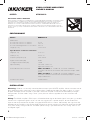 2
2
-
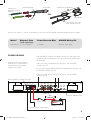 3
3
-
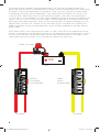 4
4
-
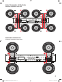 5
5
-
 6
6
-
 7
7
-
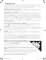 8
8
-
 9
9
-
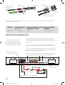 10
10
-
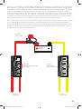 11
11
-
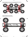 12
12
-
 13
13
-
 14
14
-
 15
15
-
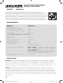 16
16
-
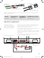 17
17
-
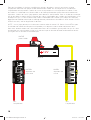 18
18
-
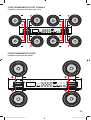 19
19
-
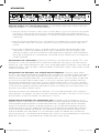 20
20
-
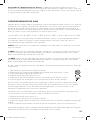 21
21
-
 22
22
-
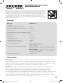 23
23
-
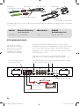 24
24
-
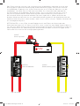 25
25
-
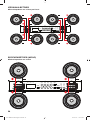 26
26
-
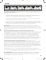 27
27
-
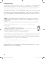 28
28
-
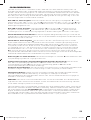 29
29
-
 30
30
-
 31
31
-
 32
32


Kicker 2021 KXMA 8-Channel Amplifier El manual del propietario
- Categoría
- Amplificador de instrumentos musicales
- Tipo
- El manual del propietario
- Este manual también es adecuado para
En otros idiomas
Documentos relacionados
-
Kicker KXMA900.5 El manual del propietario
-
-
Kicker KXMA400.2 El manual del propietario
-
Kicker 2016 DXA 4-Channel Amplifier El manual del propietario
-
-
Kicker KX400.4 Manual de usuario
-
-
-
-
Otros documentos
-
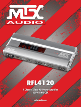 Car audio systems SE 4120 El manual del propietario
-
Peugeot EnergyBand-150 Manual de usuario
-
Yamaha XDA-AMP5400RKBL El manual del propietario
-
AudioSource Stereo Amplifier AMP210 / AMP310 Manual de usuario
-
-
-
-
AudioSource AMP210 Manual de usuario
-
