ASROCK 880GMH-U3S3 El manual del propietario
- Categoría
- Placas base
- Tipo
- El manual del propietario
Este manual también es adecuado para

11
11
1
ASRock 880GMH/U3S3 Motherboard
EnglishEnglish
EnglishEnglish
English
Copyright Notice:Copyright Notice:
Copyright Notice:Copyright Notice:
Copyright Notice:
No part of this installation guide may be reproduced, transcribed, transmitted, or trans-
lated in any language, in any form or by any means, except duplication of documen-
tation by the purchaser for backup purpose, without written consent of ASRock Inc.
Products and corporate names appearing in this guide may or may not be registered
trademarks or copyrights of their respective companies, and are used only for identifica-
tion or explanation and to the owners’ benefit, without intent to infringe.
Disclaimer:Disclaimer:
Disclaimer:Disclaimer:
Disclaimer:
Specifications and information contained in this guide are furnished for informational
use only and subject to change without notice, and should not be constructed as a
commitment by ASRock. ASRock assumes no responsibility for any errors or omissions
that may appear in this guide.
With respect to the contents of this guide, ASRock does not provide warranty of any kind,
either expressed or implied, including but not limited to the implied warranties or
conditions of merchantability or fitness for a particular purpose. In no event shall
ASRock, its directors, officers, employees, or agents be liable for any indirect, special,
incidental, or consequential damages (including damages for loss of profits, loss of
business, loss of data, interruption of business and the like), even if ASRock has been
advised of the possibility of such damages arising from any defect or error in the guide
or product.
This device complies with Part 15 of the FCC Rules. Operation is subject to the
following two conditions:
(1) this device may not cause harmful interference, and
(2) this device must accept any interference received, including interference that
may cause undesired operation.
Published February 2011
Copyright©2011 ASRock INC. All rights reserved.
CALIFORNIA, USA ONLY
The Lithium battery adopted on this motherboard contains Perchlorate, a toxic
substance controlled in Perchlorate Best Management Practices (BMP) regulations
passed by the California Legislature. When you discard the Lithium battery in
California, USA, please follow the related regulations in advance.
“Perchlorate Material-special handling may apply, see
www.dtsc.ca.gov/hazardouswaste/perchlorate”
ASRock Website: http://www.asrock.com

22
22
2
ASRock 880GMH/U3S3 Motherboard
EnglishEnglish
EnglishEnglish
English
Motherboard LayoutMotherboard Layout
Motherboard LayoutMotherboard Layout
Motherboard Layout
1 CPU Fan Connector (CPU_FAN1) 18 SATAII Connector (SATAII_2 (PORT 1), Blue)
2 ATX 12V Power Connector (ATX12V1) 19 SATAII Connector (SATAII_1 (PORT 0), Blue)
3 CPU Heatsink Retention Module 20 System Panel Header (PANEL1, White)
4 AM3+ CPU Socket 21 Chassis Speaker Header
5 2 x 240-pin DDR3 DIMM Slots (SPEAKER 1, White)
(Dual Channel A: DDR3_A1, DDR3_B1; Blue) 22 USB 2.0 Header (USB10_11, Blue)
6 2 x 240-pin DDR3 DIMM Slots 23 Clear CMOS Jumper (CLRCMOS1)
(Dual Channel B: DDR3_A2, DDR3_B2; White) 24 SATA3 Connector (SATA3_1, White)
7 ATX Power Connector (ATXPWR1) 25 SATA3 Connector (SATA3_2, White)
8 Primary IDE Connector (IDE1, Blue) 26 Infrared Module Header (IR1)
9 Consumer Infrared Module Header (CIR1) 27 Serial Port Connector (COM1)
10 Chassis Fan Connector (CHA_FAN1) 28 PCI Slots (PCI1-2)
11 USB 2.0 Header (USB6_7, Blue) 29 PCI Express 2.0 x16 Slot (PCIE2; Blue)
12 USB 2.0 Header (USB8_9, Blue) 30 PCI Express 2.0 x1 Slot (PCIE1; White)
13 Southbridge Controller 31 Power Fan Connector (PWR_FAN1)
14 SPI Flash Memory (32Mb) 32 Front Panel Audio Header
15 SATAII Connector (SATAII_5 (PORT 4), Blue) (HD_AUDIO1, White)
16 SATAII Connector (SATAII_4 (PORT 3), Blue) 33 Internal Audio Connector: CD1 (Black)
17 SATAII Connector (SATAII_3 (PORT 2), Blue) 34 Northbridge Controller

33
33
3
ASRock 880GMH/U3S3 Motherboard
EnglishEnglish
EnglishEnglish
English
I/O PI/O P
I/O PI/O P
I/O P
anelanel
anelanel
anel
** If you use 2-channel speaker, please connect the speaker’s plug into “Front Speaker Jack”.
See the table below for connection details in accordance with the type of speaker you use.
TABLE for Audio Output Connection
Audio Output Channels Front Speaker Rear Speaker Central / Bass Line In or
(No. 9) (No. 6) (No. 5) Side Speaker
(No. 8)
2 V -- -- --
4VV----
6 VVV--
8 VVVV
LAN Port
ACT/LINK
LED
SPEED
LED
* There are two LED next to the LAN port. Please refer to the table below for the LAN port LED
indications.
LAN Port LED Indications
Activity/Link LED SPEED LED
Status Description Status Description
Off No Link Off 10Mbps connection
Blinking Data Activity Orange 100Mbps connection
On Link Green 1Gbps connection
1 USB 2.0 Ports (USB23) ** 9 Front Speaker (Lime)
2 VGA/D-Sub Port 10 Microphone (Pink)
3 USB 2.0 Ports (USB45) 11 USB 3.0 Ports (USB01)
* 4 LAN RJ-45 Port 12 eSATA2 Connector (eSATA1)
5 Central / Bass (Orange) 13 HDMI Port
6 Rear Speaker (Black) 14 VGA/DVI-D Port
7 Optical SPDIF Out Port 15 PS/2 Keyboard Port (Purple)
8 Line In (Light Blue)

44
44
4
ASRock 880GMH/U3S3 Motherboard
EnglishEnglish
EnglishEnglish
English
To enable Multi-Streaming function, you need to connect a front panel audio cable to the front
panel audio header. After restarting your computer, you will find “Mixer” tool on your system.
Please select “Mixer ToolBox” , click “Enable playback multi-streaming”, and click
“ok”. Choose “2CH”, “4CH”, “6CH”, or “8CH” and then you are allowed to select “Realtek HDA
Primary output” to use Rear Speaker, Central/Bass, and Front Speaker, or select “Realtek
HDA Audio 2nd output” to use front panel audio.

55
55
5
ASRock 880GMH/U3S3 Motherboard
1.1.
1.1.
1.
IntroductionIntroduction
IntroductionIntroduction
Introduction
Thank you for purchasing ASRock 880GMH/U3S3 motherboard, a reliable
motherboard produced under ASRock’s consistently stringent quality control. It de-
livers excellent performance with robust design conforming to ASRock’s commit-
ment to quality and endurance.
In this manual, chapter 1 and 2 contain introduction of the motherboard and step-by-step
guide to the hardware installation. Chapter 3 and 4 contain the configuration guide to
BIOS setup and information of the Support CD.
Because the motherboard specifications and the BIOS software might
be updated, the content of this manual will be subject to change without
notice. In case any modifications of this manual occur, the updated
version will be available on ASRock website without further notice. You
may find the latest VGA cards and CPU support lists on ASRock website
as well. ASRock website http://www.asrock.com
If you require technical support related to this motherboard, please visit
our website for specific information about the model you are using.
www.asrock.com/support/index.asp
1.11.1
1.11.1
1.1
Package ContentsPackage Contents
Package ContentsPackage Contents
Package Contents
ASRock 880GMH/U3S3 Motherboard
(Micro ATX Form Factor: 9.6-in x 9.0-in, 24.4 cm x 22.9 cm)
ASRock 880GMH/U3S3 Quick Installation Guide
ASRock 880GMH/U3S3 Support CD
2 x Serial ATA (SATA) Data Cables (Optional)
1 x I/O Panel Shield
EnglishEnglish
EnglishEnglish
English

66
66
6
ASRock 880GMH/U3S3 Motherboard
EnglishEnglish
EnglishEnglish
English
1.21.2
1.21.2
1.2
SpecificationsSpecifications
SpecificationsSpecifications
Specifications
Platform - Micro ATX Form Factor: 9.6-in x 9.0-in, 24.4 cm x 22.9 cm
- All Solid Capacitor design
CPU - Support for Socket AM3+ processors
- Support for Socket AM3 processors: AMD Phenom
TM
II X6 /
X4 / X3 / X2 (except 920 / 940) / Athlon II X4 / X3 / X2 /
Sempron processors
- Supports 8-Core CPU
- Supports AMD OverDrive
TM
with ACC feature (Advanced
Clock Calibration)
- Supports AMD’s Cool ‘n’ Quiet
TM
Technology
- FSB 2600 MHz (5.2 GT/s)
- Supports Untied Overclocking Technology (see CAUTION 1)
- Supports Hyper-Transport 3.0 (HT 3.0) Technology
Chipset - Northbridge: AMD 880G
- Southbridge: AMD SB710
Memory - Dual Channel DDR3 Memory Technology (see CAUTION 2)
- 4 x DDR3 DIMM slots
- Support DDR3 1866(OC)/1800(OC)/1600(OC)/1333/1066/800
non-ECC, un-buffered memory (see CAUTION 3)
- Max. capacity of system memory: 32GB (see CAUTION 4)
Expansion Slot - 1 x PCI Express 2.0 x16 slot (blue @ x16 mode)
- 1 x PCI Express 2.0 x1 slot
- 2 x PCI slots
- Supports ATI
TM
Hybrid CrossFireX
TM
Graphics - Integrated AMD Radeon HD 4250 graphics
- DX10.1 class iGPU, Shader Model 4.1
- Max. shared memory 512MB (see CAUTION 5)
- Three VGA Output options: D-Sub, DVI-D and HDMI
- Supports HDMI Technology with max. resolution up to
1920x1200 (1080P)
- Supports Dual-link DVI with max. resolution up to 2560x1600
@ 75Hz
- Supports D-Sub with max. resolution up to 2048x1536
@ 85Hz
- Supports HDCP function with DVI and HDMI ports
- Supports Full HD 1080p Blu-ray (BD) / HD-DVD playback
with DVI and HDMI ports

77
77
7
ASRock 880GMH/U3S3 Motherboard
EnglishEnglish
EnglishEnglish
English
Audio - 7.1 CH HD Audio with Content Protection
(Realtek ALC892 Audio Codec)
- Premium Blu-ray audio support
LAN - PCIE x1 Gigabit LAN 10/100/1000 Mb/s
- Atheros
®
AR8151
- Supports Wake-On-LAN
Rear Panel I/O I/O Panel
- 1 x PS/2 Keyboard Port
- 1 x VGA/D-Sub Port
- 1 x VGA/DVI-D Port
- 1 x HDMI Port
- 1 x Optical SPDIF Out Port
- 4 x Ready-to-Use USB 2.0 Ports
- 1 x eSATA2 Connector
- 2 x Ready-to-Use USB 3.0 Ports
- 1 x RJ-45 LAN Port with LED (ACT/LINK LED and SPEED LED)
- HD Audio Jack: Rear Speaker/Central/Bass/Line in/
Front Speaker/Microphone (see CAUTION 6)
SATA3 - 2 x SATA3 6.0 Gb/s connectors by ASMedia ASM1061,
support NCQ, AHCI and "Hot Plug" functions
USB 3.0 - 2 x USB 3.0 ports by ASMedia ASM1042, support USB
1.0/2.0/3.0 up to 5Gb/s
Connector - 5 x SATA2 3.0 Gb/s connectors, support RAID (RAID 0,
RAID 1, RAID 10 and JBOD), NCQ, AHCI and "Hot Plug"
functions
- 2 x SATA3 6.0 Gb/s connectors
- 1 x ATA133 IDE connector (supports 2 x IDE devices)
- 1 x IR header
- 1 x CIR header
- 1 x COM port header
- CPU/Chassis/Power FAN connector
- 24 pin ATX power connector
- 4 pin 12V power connector
- CD in header
- Front panel audio connector
- 3 x USB 2.0 headers (support 6 USB 2.0 ports)
BIOS Feature - 32Mb AMI UEFI Legal BIOS with GUI support
- Supports “Plug and Play”
- ACPI 1.1 Compliance Wake Up Events
- Supports jumperfree
- SMBIOS 2.3.1 Support
- VCCM, NB, SB Voltage Multi-adjustment

88
88
8
ASRock 880GMH/U3S3 Motherboard
EnglishEnglish
EnglishEnglish
English
Support CD - Drivers, Utilities, AntiVirus Software (Trial Version), AMD
OverDrive
TM
Utility, AMD Live! Explorer, AMD Fusion, ASRock
Software Suite (CyberLink DVD Suite - OEM and Trial;
Creative Sound Blaster X-Fi MB - Trial)
Unique Feature - ASRock Extreme Tuning Utility (AXTU) (see CAUTION 7)
- Instant Boot
- ASRock Instant Flash (see CAUTION 8)
- ASRock AIWI (see CAUTION 9)
- ASRock APP Charger (see CAUTION 10)
- SmartView (see CAUTION 11)
- ASRock XFast USB (see CAUTION 12)
- Hybrid Booster:
- CPU Frequency Stepless Control (see CAUTION 13)
- ASRock U-COP (see CAUTION 14)
- Boot Failure Guard (B.F.G.)
Hardware - CPU Temperature Sensing
Monitor - Chassis Temperature Sensing
- CPU/Chassis/Power Fan Tachometer
- CPU Quiet Fan
- CPU/Chassis Fan Multi-Speed Control
- Voltage Monitoring: +12V, +5V, +3.3V, Vcore
OS - Microsoft
®
Windows
®
7 / 7 64-bit / Vista
TM
/ Vista
TM
64-bit
/ XP / XP Media Center / XP 64-bit compliant
Certifications - FCC, CE, WHQL
- ErP/EuP Ready (ErP/EuP ready power supply is required)
(see CAUTION 15)
* For detailed product information, please visit our website: http://www.asrock.com
WARNING
Please realize that there is a certain risk involved with overclocking, including adjusting
the setting in the BIOS, applying Untied Overclocking Technology, or using the third-
party overclocking tools. Overclocking may affect your system stability, or even
cause damage to the components and devices of your system. It should be done at
your own risk and expense. We are not responsible for possible damage caused by
overclocking.

99
99
9
ASRock 880GMH/U3S3 Motherboard
EnglishEnglish
EnglishEnglish
English
CAUTION!
1. This motherboard supports Untied Overclocking Technology. Please read “Un-
tied Overclocking Technology” on page 30 for details.
2. This motherboard supports Dual Channel Memory Technology. Before you
implement Dual Channel Memory Technology, make sure to read the
installation guide of memory modules on page 14 for proper installation.
3. Whether 1866/1800/1600MHz memory speed is supported depends on the
AM3/AM3+ CPU you adopt. If you want to adopt DDR3 1866/1800/1600
memory module on this motherboard, please refer to the memory support
list on our website for the compatible memory modules.
ASRock website http://www.asrock.com
4. Due to the operating system limitation, the actual memory size may be
less than 4GB for the reservation for system usage under Windows
®
7 /
Vista
TM
/ XP. For Windows
®
OS with 64-bit CPU, there is no such limitation.
5. The maximum shared memory size is defined by the chipset vendor and
is subject to change. Please check AMD website for the latest information.
6. For microphone input, this motherboard supports both stereo and mono modes.
For audio output, this motherboard supports 2-channel, 4-channel, 6-channel,
and 8-channel modes. Please check the table on page 3 for proper connection.
7. ASRock Extreme Tuning Utility (AXTU) is an all-in-one tool to ne-tune
different system functions in a user-friendly interface, which is including
Hardware Monitor, Fan Control, Overclocking, OC DNA and IES. In Hard-
ware Monitor, it shows the major readings of your system. In Fan Control,
it shows the fan speed and temperature for you to adjust. In Overclocking,
you are allowed to overclock CPU frequency for optimal system
performance. In OC DNA, you can save your OC settings as a profile and
share with your friends. Your friends then can load the OC profile to their
own system to get the same OC settings. In IES (Intelligent Energy
Saver), the voltage regulator can reduce the number of output phases to
improve efficiency when the CPU cores are idle without sacrificing
computing performance. Please visit our website for the operation proce-
dures of ASRock Extreme Tuning Utility (AXTU).
ASRock website: http://www.asrock.com
8. ASRock Instant Flash is a BIOS flash utility embedded in Flash ROM.
This convenient BIOS update tool allows you to update system BIOS
without entering operating systems first like MS-DOS or Windows
®
. With
this utility, you can press <F6> key during the POST or press <F2> key to
BIOS setup menu to access ASRock Instant Flash. Just launch this tool
and save the new BIOS file to your USB flash drive, floppy disk or hard
drive, then you can update your BIOS only in a few clicks without prepar-
ing an additional floppy diskette or other complicated flash utility. Please
be noted that the USB flash drive or hard drive must use FAT32/16/12 file
system.

1010
1010
10
ASRock 880GMH/U3S3 Motherboard
EnglishEnglish
EnglishEnglish
English
9. To experience intuitive motion controlled games is no longer only available
at Wii. ASRock AIWI utility introduces a new way of PC gaming operation.
ASRock AIWI is the world's first utility to turn your iPhone/iPod touch as
a game joystick to control your PC games. All you have to do is just to
install the ASRock AIWI utility either from ASRock official website or
ASRock software support CD to your motherboard, and also download the
free AIWI Lite from App store to your iPhone/iPod touch. Connecting your
PC and apple devices via Bluetooth or WiFi networks, then you can start
experiencing the exciting motion controlled games. Also, please do not
forget to pay attention to ASRock official website regularly, we will
continuously provide you the most up-do-date supported games!
ASRock website: http://www.asrock.com/Feature/Aiwi/index.asp
10. If you desire a faster, less restricted way of charging your Apple devices,
such as iPhone/iPod/iPad Touch, ASRock has prepared a wonderful
solution for you - ASRock APP Charger. Simply installing the APP Charger
driver, it makes your iPhone charged much quickly from your computer
and up to 40% faster than before. ASRock APP Charger allows you to
quickly charge many Apple devices simultaneously and even supports
continuous charging when your PC enters into Standby mode (S1), Sus-
pend to RAM (S3), hibernation mode (S4) or power off (S5). With APP
Charger driver installed, you can easily enjoy the marvelous charging
experience than ever.
ASRock website: http://www.asrock.com/Feature/AppCharger/index.asp
11. SmartView, a new function of internet browser, is the smart start page for
IE that combines your most visited web sites, your history, your Facebook
friends and your real-time newsfeed into an enhanced view for a more
personal Internet experience. ASRock motherboards are exclusively
equipped with the SmartView utility that helps you keep in touch with
friends on-the-go. To use SmartView feature, please make sure your OS
version is Windows
®
7 / 7 64 bit / Vista
TM
/ Vista
TM
64 bit, and your browser
version is IE8.
ASRock website: http://www.asrock.com/Feature/SmartView/index.asp
12. ASRock XFast USB can boost USB storage device performance. The
performance may depend on the property of the device.
13. Although this motherboard offers stepless control, it is not recommended
to perform over-clocking. Frequencies other than the recommended CPU
bus frequencies may cause the instability of the system or damage the
CPU.
14. While CPU overheat is detected, the system will automatically shutdown.
Before you resume the system, please check if the CPU fan on the
motherboard functions properly and unplug the power cord, then plug it
back again. To improve heat dissipation, remember to spray thermal
grease between the CPU and the heatsink when you install the PC system.

1111
1111
11
ASRock 880GMH/U3S3 Motherboard
EnglishEnglish
EnglishEnglish
English
15. EuP, stands for Energy Using Product, was a provision regulated by
European Union to define the power consumption for the completed system.
According to EuP, the total AC power of the completed system shall be
under 1.00W in off mode condition. To meet EuP standard, an EuP ready
motherboard and an EuP ready power supply are required. According to
Intel’s suggestion, the EuP ready power supply must meet the standard of
5v standby power efficiency is higher than 50% under 100 mA current
consumption. For EuP ready power supply selection, we recommend you
checking with the power supply manufacturer for more details.

1212
1212
12
ASRock 880GMH/U3S3 Motherboard
2.2.
2.2.
2.
InstallationInstallation
InstallationInstallation
Installation
This is a Micro ATX form factor (9.6-in x 9.0-in, 24.4 cm x 22.9 cm) motherboard.
Before you install the motherboard, study the configuration of your chassis to en-
sure that the motherboard fits into it.
Pre-installation PrecautionsPre-installation Precautions
Pre-installation PrecautionsPre-installation Precautions
Pre-installation Precautions
Take note of the following precautions before you install motherboard
components or change any motherboard settings.
Before you install or remove any component, ensure that the
power is switched off or the power cord is detached from the
power supply. Failure to do so may cause severe damage to the
motherboard, peripherals, and/or components.
1. Unplug the power cord from the wall socket before touching any
component.
2. To avoid damaging the motherboard components due to static
electricity, NEVER place your motherboard directly on the carpet or
the like. Also remember to use a grounded wrist strap or touch a
safety grounded object before you handle components.
3. Hold components by the edges and do not touch the ICs.
4. Whenever you uninstall any component, place it on a grounded anti-
static pad or in the bag that comes with the component.
5. When placing screws into the screw holes to secure the motherboard
to the chassis, please do not over-tighten the screws! Doing so may
damage the motherboard.
EnglishEnglish
EnglishEnglish
English

1313
1313
13
ASRock 880GMH/U3S3 Motherboard
EnglishEnglish
EnglishEnglish
English
2.12.1
2.12.1
2.1
CPU InstallationCPU Installation
CPU InstallationCPU Installation
CPU Installation
Step 1. Unlock the socket by lifting the lever up to a 90
o
angle.
Step 2. Position the CPU directly above the socket such that the CPU corner with
the golden triangle matches the socket corner with a small triangle.
Step 3. Carefully insert the CPU into the socket until it fits in place.
The CPU fits only in one correct orientation. DO NOT force the CPU
into the socket to avoid bending of the pins.
Step 4. When the CPU is in place, press it firmly on the socket while you push
down the socket lever to secure the CPU. The lever clicks on the side tab
to indicate that it is locked.
2.22.2
2.22.2
2.2
Installation of CPU Fan and HeatsinkInstallation of CPU Fan and Heatsink
Installation of CPU Fan and HeatsinkInstallation of CPU Fan and Heatsink
Installation of CPU Fan and Heatsink
After you install the CPU into this motherboard, it is necessary to install a
larger heatsink and cooling fan to dissipate heat. You also need to spray
thermal grease between the CPU and the heatsink to improve heat
dissipation. Make sure that the CPU and the heatsink are securely fas-
tened and in good contact with each other. Then connect the CPU fan to
the CPU FAN connector (CPU_FAN1, see Page 2, No. 1). For proper
installation, please kindly refer to the instruction manuals of the CPU fan
and the heatsink.
STEP 1:
Lift Up The Socket Lever
STEP 2 / STEP 3:
Match The CPU Golden Triangle
To The Socket Corner Small
Triangle
STEP 4:
Push Down And Lock
The Socket Lever
Lever 90° Up
CPU Golden Triangle
Socker Corner
Small Triangle

1414
1414
14
ASRock 880GMH/U3S3 Motherboard
EnglishEnglish
EnglishEnglish
English
2.3 Installation of Memory Modules (DIMM)2.3 Installation of Memory Modules (DIMM)
2.3 Installation of Memory Modules (DIMM)2.3 Installation of Memory Modules (DIMM)
2.3 Installation of Memory Modules (DIMM)
This motherboard provides four 240-pin DDR3 (Double Data Rate 3) DIMM slots,
and supports Dual Channel Memory Technology. For dual channel configuration,
you always need to install identical (the same brand, speed, size and chip-
type) DDR3 DIMM pair in the slots of the same color. In other words, you have to
install identical DDR3 DIMM pair in Dual Channel A (DDR3_A1 and DDR3_B1;
Blue slots; see p.2 No.5) or identical DDR3 DIMM pair in Dual Channel B
(DDR3_A2 and DDR3_B2; White slots; see p.2 No.6), so that Dual Channel
Memory Technology can be activated. This motherboard also allows you to
install four DDR3 DIMMs for dual channel configuration, and please install iden-
tical DDR3 DIMMs in all four slots. You may refer to the Dual Channel Memory
Configuration Table below.
Dual Channel Memory Configurations
DDR3_A1 DDR3_B1 DDR3_A2 DDR3_B2
(Blue Slot) (Blue Slot) (White Slot) (White Slot)
(1) Populated Populated - -
(2) - - Populated Populated
(3)* Populated Populated Populated Populated
* For the configuration (3), please install identical DDR3 DIMMs in all four
slots.
1. If you want to install two memory modules, for optimal compatibility
and reliability, it is recommended to install them in the slots of the
same color. In other words, install them either in the set of blue slots
(DDR3_A1 and DDR3_B1), or in the set of white slots (DDR3_A2
and DDR3_B2).
2. If only one memory module or three memory modules are installed
in the DDR3 DIMM slots on this motherboard, it is unable to activate
the Dual Channel Memory Technology.
3. If a pair of memory modules is NOT installed in the same Dual
Channel, for example, installing a pair of memory modules in
DDR3_A1 and DDR3_A2, it is unable to activate the Dual Channel
Memory Technology .
4. It is not allowed to install a DDR or DDR2 memory module into
DDR3 slot; otherwise, this motherboard and DIMM may be damaged.
5. If you adopt DDR3 1866/1800/1600 memory modules on this
motherboard, it is recommended to install them on DDR3_A2 and
DDR3_B2 slots.

1515
1515
15
ASRock 880GMH/U3S3 Motherboard
EnglishEnglish
EnglishEnglish
English
Installing a DIMMInstalling a DIMM
Installing a DIMMInstalling a DIMM
Installing a DIMM
Please make sure to disconnect power supply before adding or
removing DIMMs or the system components.
Step 1. Unlock a DIMM slot by pressing the retaining clips outward.
Step 2. Align a DIMM on the slot such that the notch on the DIMM matches the break
on the slot.
The DIMM only fits in one correct orientation. It will cause permanent
damage to the motherboard and the DIMM if you force the DIMM into the
slot at incorrect orientation.
Step 3. Firmly insert the DIMM into the slot until the retaining clips at both ends fully
snap back in place and the DIMM is properly seated.

1616
1616
16
ASRock 880GMH/U3S3 Motherboard
EnglishEnglish
EnglishEnglish
English
2.4 Expansion Slots (PCI and PCI Express Slots)2.4 Expansion Slots (PCI and PCI Express Slots)
2.4 Expansion Slots (PCI and PCI Express Slots)2.4 Expansion Slots (PCI and PCI Express Slots)
2.4 Expansion Slots (PCI and PCI Express Slots)
There are 2 PCI slots and 2 PCI Express slots on this motherboard.
PCI Slots: PCI slots are used to install expansion cards that have the 32-bit PCI
interface.
PCIE Slots:
PCIE1 (PCIE x1 slot; White) is used for PCI Express cards with x1 lane
width cards, such as Gigabit LAN card and SATA2 card.
PCIE2 (PCIE x16 slot; Blue) is used for PCI Express x16 lane width
graphics cards.
Installing an expansion cardInstalling an expansion card
Installing an expansion cardInstalling an expansion card
Installing an expansion card
Step 1. Before installing the expansion card, please make sure that the power
supply is switched off or the power cord is unplugged. Please read the
documentation of the expansion card and make necessary hardware
settings for the card before you start the installation.
Step 2. Remove the system unit cover (if your motherboard is already installed in
a chassis).
Step 3. Remove the bracket facing the slot that you intend to use. Keep the
screws for later use.
Step 4. Align the card connector with the slot and press firmly until the card is
completely seated on the slot.
Step 5. Fasten the card to the chassis with screws.
Step 6. Replace the system cover.

1717
1717
17
ASRock 880GMH/U3S3 Motherboard
EnglishEnglish
EnglishEnglish
English
2. If you have installed onboard VGA driver from our support CD to your system
already, you can freely enjoy the benefits of dual monitor function after your
system boots. If you haven’t installed onboard VGA driver yet, please install
onboard VGA driver from our support CD to your system and restart your
computer. Then you can start to use dual monitor function on this motherboard.
1. DVI-D and HDMI ports cannot function at the same time. When one of
them is enabled, the other one will be disabled.
2. When you playback HDCP-protected video from Blu-ray (BD) or
HD-DVD disc, the content will be displayed only in one of the two
monitors instead of both monitors.
2.5 Dual Monitor and Surround Display Features2.5 Dual Monitor and Surround Display Features
2.5 Dual Monitor and Surround Display Features2.5 Dual Monitor and Surround Display Features
2.5 Dual Monitor and Surround Display Features
Dual Monitor Feature
This motherboard supports dual monitor feature. With the internal VGA output
support (DVI-D, D-Sub and HDMI), you can easily enjoy the benefits of dual monitor
feature without installing any add-on VGA card to this motherboard. This
motherboard also provides independent display controllers for DVI-D, D-Sub and
HDMI to support dual VGA output so that DVI-D, D-sub and HDMI can drive same or
different display contents.
To enable dual monitor feature, please follow the below steps:
1. Connect DVI-D monitor cable to VGA/DVI-D port on the I/O panel, connect D-Sub
monitor cable to VGA/D-Sub port on the I/O panel, or connect HDMI monitor
cable to HDMI port on the I/O panel.
VGA/DVI-D port
HDMI port
VGA/D-Sub port

1818
1818
18
ASRock 880GMH/U3S3 Motherboard
EnglishEnglish
EnglishEnglish
English
Surround Display Feature
This motherboard supports surround display upgrade. With the internal VGA
output support (DVI-D, D-Sub and HDMI) and external add-on PCI Express VGA
cards, you can easily enjoy the benefits of surround display feature.
Please refer to the following steps to set up a surround display environment:
1. Install the ATI
TM
PCI Express VGA card on PCIE2 slot. Please refer to page 16 for
proper expansion card installation procedures for details.
2. Connect DVI-D monitor cable to VGA/DVI-D port on the I/O panel, connect D-Sub
monitor cable to VGA/D-Sub port on the I/O panel, or connect HDMI monitor
cable to HDMI port on the I/O panel. Then connect other monitor cables to the
corresponding connectors of the add-on PCI Express VGA card on PCIE2 slot.
3. Boot your system. Press <F2> to enter UEFI setup. Enter “Share Memory”
option to adjust the memory capability to [32MB], [64MB], [128MB] [256MB] or
[512MB] to enable the function of VGA/D-sub. Please make sure that the value
you select is less than the total capability of the system memory. If you do not
adjust the UEFI setup, the default value of “Share Memory”, [Auto], will disable
VGA/D-Sub function when the add-on VGA card is inserted to this
motherboard.
4. Install the onboard VGA driver and the add-on PCI Express VGA card driver to
your system. If you have installed the drivers already, there is no need to install
them again.
5. Set up a multi-monitor display.
For Windows
®
XP / XP 64-bit OS:
Right click the desktop, choose “Properties”, and select the “Settings” tab
so that you can adjust the parameters of the multi-monitor according to the
steps below.
A. Click the “Identify” button to display a large number on each monitor.
B. Right-click the display icon in the Display Properties dialog that you wish
to be your primary monitor, and then select “Primary”. When you use
multiple monitors with your card, one monitor will always be Primary,
and all additional monitors will be designated as Secondary.
C. Select the display icon identified by the number 2.
D. Click “Extend my Windows desktop onto this monitor”.
E. Right-click the display icon and select “Attached”, if necessary.
F. Set the “Screen Resolution” and “Color Quality” as appropriate for the
second monitor. Click “Apply” or “OK” to apply these new values.
G. Repeat steps C through E for the diaplay icon identified by the number
one, two, three and four.

1919
1919
19
ASRock 880GMH/U3S3 Motherboard
EnglishEnglish
EnglishEnglish
English
HDCP Function
HDCP function is supported on this motherboard. To use HDCP
function with this motherboard, you need to adopt the monitor that
supports HDCP function as well. Therefore, you can enjoy the
superior display quality with high-definition HDCP encryption
contents. Please refer to below instruction for more details about
HDCP function.
What is HDCP?
HDCP stands for High-Bandwidth Digital Content Protection, a
specification developed by Intel
®
for protecting digital entertainment
content that uses the DVI interface. HDCP is a copy protection
scheme to eliminate the possibility of intercepting digital data
midstream between the video source, or transmitter - such as a
computer, DVD player or set-top box - and the digital display, or
receiver - such as a monitor, television or projector. In other words,
HDCP specification is designed to protect the integrity of content as it
is being transmitted.
Products compatible with the HDCP scheme such as DVD players,
satellite and cable HDTV set-top-boxes, as well as few entertain-
ment PCs requires a secure connection to a compliant display. Due
to the increase in manufacturers employing HDCP in their equipment,
it is highly recommended that the HDTV or LCD monitor you purchase
is compatible.
For Windows
®
7 / 7 64-bit / Vista
TM
/ Vista
TM
64-bit OS:
Right click the desktop, choose “Personalize”, and select the “Display
Settings” tab so that you can adjust the parameters of the multi-monitor
according to the steps below.
A. Click the number ”2” icon.
B. Click the items “This is my main monitor” and “Extend the desktop onto
this monitor”.
C. Click “OK” to save your change.
D. Repeat steps A through C for the display icon identified by the number
three and four.
6. Use Surround Display. Click and drag the display icons to positions representing
the physical setup of your monitors that you would like to use. The placement
of display icons determines how you move items from one monitor to another.

2020
2020
20
ASRock 880GMH/U3S3 Motherboard
EnglishEnglish
EnglishEnglish
English
2.62.6
2.62.6
2.6
ATIATI
ATIATI
ATI
TMTM
TMTM
TM
Hybrid CrossFireX Hybrid CrossFireX
Hybrid CrossFireX Hybrid CrossFireX
Hybrid CrossFireX
TMTM
TMTM
TM
Operation Guide Operation Guide
Operation Guide Operation Guide
Operation Guide
This motherboard supports ATI
TM
Hybrid CrossFireX
TM
feature. ATI
TM
Hybrid
CrossFireX
TM
brings multi-GPU performance capabilities by enabling an AMD 880G
integrated graphics processor and a discrete graphics processor to operate
simultaneously with combined output to a single display for blisteringly-fast frame
rates. Currently, ATI
TM
Hybrid CrossFireX
TM
Technology is only supported with
Windows
®
Vista
TM
/ 7 OS, and is not available with Windows
®
XP OS. In the future,
ATI
TM
Hybrid CrossFireX
TM
may be supported with Windows
®
XP OS.
Enjoy the benefit of ATIEnjoy the benefit of ATI
Enjoy the benefit of ATIEnjoy the benefit of ATI
Enjoy the benefit of ATI
TMTM
TMTM
TM
Hybrid CrossFireX Hybrid CrossFireX
Hybrid CrossFireX Hybrid CrossFireX
Hybrid CrossFireX
TMTM
TMTM
TM
Step 1. Install one compatible PCI Express graphics card to PCIE2 slot (blue). For
the proper installation procedures, please refer to section “Expansion Slots”.
Step 2. Connect the monitor cable to the correspondent connector on the PCI
Express graphics card on PCIE2 slot.
Step 3. Boot your system. Press <F2> to enter UEFI setup. Enter “Advanced”
screen, and enter “North Bridge Configuration”. Then set the option “Sur-
round View” to [Enabled].
Step 4. Boot into OS. Please remove the ATI
TM
driver if you have any VGA driver
installed in your system.
Step 5. Install the onboard VGA driver from our support CD to your system for both
the onboard VGA and the discrete graphics card.
Step 6. Restart your computer. Then you will find “ATI Catalyst Control Center” on
your Windows
®
taskbar.
ATI Catalyst Control Center
Vendor Chipset Model Driver
ATI RADEON HD2400XT POWERCOLOR HD2400 XT Support CD 8.71
256MB DDR3
RADEON HD3450 POWERCOLOR AX3450 Support CD 8.71
256MD2-S
What does an ATI
TM
Hybrid CrossFireX
TM
system include?
An ATI
TM
Hybrid CrossFireX
TM
system includes an ATI
TM
Radeon
TM
2400 or ATI
TM
Radeon
TM
3450 series graphics processor and a motherboard based on an AMD
880G integrated chipset, all operating in a Windows
®
Vista
TM
/ 7 environment. Please
refer to below PCI Express graphics card support list for ATI
TM
Hybrid CrossFireX
TM
.
For the future update of more compatible PCI Express graphics cards, please visit
our website for further information.

2121
2121
21
ASRock 880GMH/U3S3 Motherboard
EnglishEnglish
EnglishEnglish
English
* Hybrid CrossFireX
TM
appearing here is a registered trademark of ATI
TM
Technologies Inc.,
and is used only for identification or explanation and to the owners’ benefit, without intent to
infringe.
* For further information of ATI
TM
Hybrid CrossFireX
TM
technology, please check AMD website
for up dates and details.
Step 7. Double-click “ATI Catalyst Control Center”. Click “View”, click “CrossFire
TM
”,
and then select the option “Enable CrossFire
TM
”.
View
CrossFire
TM
Enable CrossFire
TM
Step 8. Click “Yes” to continue.
Step 9. Click “OK” to save your change.
Step 10. Reboot your system. Then you can freely enjoy the benefit of Hybrid
TM
CrossFireX
TM
feature.

2222
2222
22
ASRock 880GMH/U3S3 Motherboard
2.72.7
2.72.7
2.7
ASRock Smart Remote Installation GuideASRock Smart Remote Installation Guide
ASRock Smart Remote Installation GuideASRock Smart Remote Installation Guide
ASRock Smart Remote Installation Guide
ASRock Smart Remote is only used for ASRock motherboard with CIR header.
Please refer to below procedures for the quick installation and usage of ASRock
Smart Remote.
Step1. Find the CIR header located next to
the USB 2.0 header on ASRock
motherboard.
Step2. Connect the front USB cable to the
USB 2.0 header (as below, pin 1-5)
and the CIR header. Please
make sure the wire assignments and
the pin assignments are matched
correctly.
Step3. Install Multi-Angle CIR Receiver to
the front USB port. If Multi-Angle CIR
Receiver cannot successfully receive
the infrared signals from MCE
Remote Controller, please try to
install it to the other front USB port.
USB 2.0 header (9-pin, blue)
CIR header (4-pin, white)
3 CIR sensors in different angles
1. Only one of the front USB port can support CIR function. When
the CIR function is enabled, the other port will remain USB
function.
2. Multi-Angle CIR Receiver is used for front USB only. Please do
not use the rear USB bracket to connect it on the rear panel.
Multi-Angle CIR Receiver can receive the multi-direction infrared
signals (top, down and front), which is compatible with most of
the chassis on the market.
3. The Multi-Angle CIR Receiver does not support Hot-Plug
function. Please install it before you boot the system.
* ASRock Smart Remote is only supported by some of ASRock motherboards. Please refer to
ASRock website for the motherboard support list:
http://www.asrock.com
USB_PWR
P-
P+
GND
DUMMY
ATX+5VSB
IRRX
IRTX
GND
EnglishEnglish
EnglishEnglish
English

2323
2323
23
ASRock 880GMH/U3S3 Motherboard
EnglishEnglish
EnglishEnglish
English
OpenShort
Clear CMOSDefault
2.82.8
2.82.8
2.8
Jumpers SetupJumpers Setup
Jumpers SetupJumpers Setup
Jumpers Setup
The illustration shows how jumpers are
setup. When the jumper cap is placed on
pins, the jumper is “Short”. If no jumper cap
is placed on pins, the jumper is “Open”. The
illustration shows a 3-pin jumper whose pin1
and pin2 are “Short” when jumper cap is
placed on these 2 pins.
Jumper Setting
Clear CMOS Jumper
(CLRCMOS1)
(see p.2, No. 23)
Note: CLRCMOS1 allows you to clear the data in CMOS. The data in CMOS includes
system setup information such as system password, date, time, and system
setup parameters. To clear and reset the system parameters to default setup,
please turn off the computer and unplug the power cord from the power
supply. After waiting for 15 seconds, use a jumper cap to short pin2 and pin3
on CLRCMOS1 for 5 seconds. However, please do not clear the CMOS right
after you update the BIOS. If you need to clear the CMOS when you just finish
updating the BIOS, you must boot up the system first, and then shut it down
before you do the clear-CMOS action.

2424
2424
24
ASRock 880GMH/U3S3 Motherboard
EnglishEnglish
EnglishEnglish
English
Serial ATAII Connectors These five Serial ATAII (SATAII)
(SATAII_1 (PORT 0): connectors support SATAII
see p.2, No. 19) or SATA hard disk for internal
(SATAII_2 (PORT 1): storage devices. The current
see p.2, No. 18) SATAII interface allows up to
(SATAII_3 (PORT 2): 3.0 Gb/s data transfer rate.
see p.2, No. 17)
(SATAII_4 (PORT 3):
see p.2, No. 16)
(SATAII_5 (PORT 4):
see p.2, No. 15)
Serial ATA (SATA) Either end of the SATA data cable
Data Cable can be connected to the SATAII /
(Optional) SATA3 hard disk or the SATAII /
SATA3 connector on this
motherboard.
2.9 Onboard Headers and Connectors2.9 Onboard Headers and Connectors
2.9 Onboard Headers and Connectors2.9 Onboard Headers and Connectors
2.9 Onboard Headers and Connectors
Onboard headers and connectors are NOT jumpers. Do NOT place
jumper caps over these headers and connectors. Placing jumper caps
over the headers and connectors will cause permanent damage of the
motherboard!
Primary IDE connector (Blue)
(39-pin IDE1, see p.2 No. 8)
Note: Please refer to the instruction of your IDE device vendor for the details.
connect the black end
to the IDE devices
connect the blue end
to the motherboard
80-conductor ATA 66/100/133 cable
SATAII_1 (PORT 0)
SATAII_2 (PORT 1)
SATAII_3 (PORT 2)
SATAII_4 (PORT 3)
SATAII_5 (PORT 4)
Serial ATA3 Connectors These two Serial ATA3
(SATA3_1: see p.2, No. 24) (SATA3) connectors support
(SATA3_2: see p.2, No. 25) SATA data cables for internal
storage devices. The current
SATA3 interface allows up to
6.0 Gb/s data transfer rate.
SATA3_2 SATA3_1

2525
2525
25
ASRock 880GMH/U3S3 Motherboard
EnglishEnglish
EnglishEnglish
English
USB 2.0 Headers Besides four default USB 2.0
(9-pin USB10_11) ports on the I/O panel, there are
(see p.2 No. 22) three USB 2.0 headers on this
motherboard. Each USB 2.0
header can support two USB
2.0 ports.
(9-pin USB8_9)
(see p.2 No. 12)
(9-pin USB6_7)
(see p.2 No. 11)
Consumer Infrared Module Header This header can be used to
(4-pin CIR1) connect the remote
(see p.2 No. 9) controller receiver.
Infrared Module Header This header supports an
(5-pin IR1) optional wireless transmitting
(see p.2 No. 26) and receiving infrared module.
Front Panel Audio Header This is an interface for the front
(9-pin HD_AUDIO1) panel audio cable that allows
(see p.2, No. 32) convenient connection and
control of audio devices.
Internal Audio Connectors This connector allows you
(4-pin CD1) to receive stereo audio input
(CD1: see p.2 No. 33) from sound sources such as
a CD-ROM, DVD-ROM, TV
tuner card, or MPEG card.
CD1

2626
2626
26
ASRock 880GMH/U3S3 Motherboard
EnglishEnglish
EnglishEnglish
English
Chassis and Power Fan Connectors Please connect the fan cables
(4-pin CHA_FAN1) to the fan connectors and
(see p.2 No. 10) match the black wire to the
(3-pin PWR_FAN1)
(see p.2 No. 31)
CPU Fan Connector Please connect the CPU fan
(4-pin CPU_FAN1) cable to this connector and
(see p.2 No. 1) match the black wire to the
ground pin.
Though this motherboard provides 4-Pin CPU fan (Quiet Fan) support, the 3-Pin
CPU fan still can work successfully even without the fan speed control function.
If you plan to connect the 3-Pin CPU fan to the CPU fan connector on this
motherboard, please connect it to Pin 1-3.
Chassis Speaker Header Please connect the chassis
(4-pin SPEAKER 1) speaker to this header.
(see p.2 No. 21)
System Panel Header This header accommodates
(9-pin PANEL1) several system front panel
(see p.2 No. 20) functions.
1. High Definition Audio supports Jack Sensing, but the panel wire on
the chassis must support HDA to function correctly. Please follow the
instruction in our manual and chassis manual to install your system.
2. If you use AC’97 audio panel, please install it to the front panel audio
header as below:
A. Connect Mic_IN (MIC) to MIC2_L.
B. Connect Audio_R (RIN) to OUT2_R and Audio_L (LIN) to OUT2_L.
C. Connect Ground (GND) to Ground (GND).
D. MIC_RET and OUT_RET are for HD audio panel only. You don’t
need to connect them for AC’97 audio panel.
E. To activate the front mic.
For Windows
®
XP / XP 64-bit OS:
Select “Mixer”. Select “Recorder”. Then click “FrontMic”.
For Windows
®
7 / 7 64-bit / Vista
TM
/ Vista
TM
64-bit OS:
Go to the "FrontMic" Tab in the Realtek Control panel. Adjust
“Recording Volume”.
4
3
2
1
3-Pin Fan Installation
Pin 1-3 Connected

2727
2727
27
ASRock 880GMH/U3S3 Motherboard
EnglishEnglish
EnglishEnglish
English
ATX Power Connector Please connect an ATX power
(24-pin ATXPWR1) supply to this connector.
(see p.2 No. 7)
20-Pin ATX Power Supply Installation
Though this motherboard provides 24-pin ATX power connector,
it can still work if you adopt a traditional 20-pin ATX power supply.
To use the 20-pin ATX power supply, please plug your power
supply along with Pin 1 and Pin 13.
12
1
24
13
12
1
24
13
o
ATX 12V Power Connector Please connect an ATX 12V
(4-pin ATX12V1) power supply to this connector.
(see p.2 No. 2)
Serial port Header This COM1 header supports a
(9-pin COM1) serial port module.
(see p.2 No.27)

2828
2828
28
ASRock 880GMH/U3S3 Motherboard
EnglishEnglish
EnglishEnglish
English
2.102.10
2.102.10
2.10
Driver Installation GuideDriver Installation Guide
Driver Installation GuideDriver Installation Guide
Driver Installation Guide
To install the drivers to your system, please insert the support CD to your optical
drive first. Then, the drivers compatible to your system can be auto-detected and
listed on the support CD driver page. Please follow the order from up to bottom
side to install those required drivers. Therefore, the drivers you install can work
properly.
2.112.11
2.112.11
2.11
Installing WindowsInstalling Windows
Installing WindowsInstalling Windows
Installing Windows
®®
®®
®
7 / 7 64-bit / Vista 7 / 7 64-bit / Vista
7 / 7 64-bit / Vista 7 / 7 64-bit / Vista
7 / 7 64-bit / Vista
TMTM
TMTM
TM
/ /
/ /
/
VistaVista
VistaVista
Vista
TMTM
TMTM
TM
64-bit / XP / XP 64-bit With RAID Functions 64-bit / XP / XP 64-bit With RAID Functions
64-bit / XP / XP 64-bit With RAID Functions 64-bit / XP / XP 64-bit With RAID Functions
64-bit / XP / XP 64-bit With RAID Functions
If you want to install Windows
®
7 / 7 64-bit / Vista
TM
/ Vista
TM
64-bit / XP / XP 64-bit on
your SATA / SATAII HDDs with RAID functions, please refer to the document at the
following path in the Support CD for detailed procedures:
..\ RAID Installation Guide
Please be noted that currently SATA3 connectors do not support RAID
functions. If you want to use RAID functions, please use SATAII
connectors.
Using SATAII / SATA3 HDDs without NCQ and Hot Plug functions (IDE mode)
STEP 1: Set up UEFI.
A. Enter UEFI SETUP UTILITY Advanced screen Storage
Configuration.
B. Set the “SATA Mode” option to [IDE] for SATAII HDDs.
Set the “ASM1061 SATA3 Operation Mode” option to [IDE] for SATA3
HDDs.
STEP 2: Install Windows
®
XP / XP 64-bit OS on your system.
2.122.12
2.122.12
2.12
Installing WindowsInstalling Windows
Installing WindowsInstalling Windows
Installing Windows
®®
®®
®
7 / 7 64-bit / Vista 7 / 7 64-bit / Vista
7 / 7 64-bit / Vista 7 / 7 64-bit / Vista
7 / 7 64-bit / Vista
TMTM
TMTM
TM
/ /
/ /
/
VistaVista
VistaVista
Vista
TMTM
TMTM
TM
64-bit / XP / XP 64-bit Without RAID Functions 64-bit / XP / XP 64-bit Without RAID Functions
64-bit / XP / XP 64-bit Without RAID Functions 64-bit / XP / XP 64-bit Without RAID Functions
64-bit / XP / XP 64-bit Without RAID Functions
If you want to install Windows
®
7 / 7 64-bit / Vista
TM
/ Vista
TM
64-bit / XP / XP 64-bit OS
on your SATAII / SATA3 HDDs without RAID functions, please follow below procedures
according to the OS you install.
2.12.1 Installing Windows2.12.1 Installing Windows
2.12.1 Installing Windows2.12.1 Installing Windows
2.12.1 Installing Windows
®®
®®
®
XP / XP 64-bit Without RAID XP / XP 64-bit Without RAID
XP / XP 64-bit Without RAID XP / XP 64-bit Without RAID
XP / XP 64-bit Without RAID
Functions Functions
Functions Functions
Functions
If you want to install Windows
®
XP / XP 64-bit on your SATAII / SATA3 HDDs without
RAID functions, please follow below steps.

2929
2929
29
ASRock 880GMH/U3S3 Motherboard
EnglishEnglish
EnglishEnglish
English
STEP 1: Set up UEFI.
A. Enter UEFI SETUP UTILITY Advanced screen Storage
Configuration.
B. Set the “SATA Mode” option to [IDE] for SATAII HDDs.
Set the “ASM1061 SATA3 Operation Mode” option to [IDE] for SATA3
HDDs.
STEP 2: Install Windows
®
7 / 7 64-bit / Vista
TM
/ Vista
TM
64-bit OS on your
system.
Using SATAII / SATA3 HDDs without NCQ and Hot Plug functions (IDE mode)
2.12.2 Installing Windows2.12.2 Installing Windows
2.12.2 Installing Windows2.12.2 Installing Windows
2.12.2 Installing Windows
®®
®®
®
7 / 7 64-bit / Vista 7 / 7 64-bit / Vista
7 / 7 64-bit / Vista 7 / 7 64-bit / Vista
7 / 7 64-bit / Vista
TMTM
TMTM
TM
/ /
/ /
/
Vista Vista
Vista Vista
Vista
TMTM
TMTM
TM
64-bit Without RAID Functions 64-bit Without RAID Functions
64-bit Without RAID Functions 64-bit Without RAID Functions
64-bit Without RAID Functions
If you want to install Windows
®
7 / 7 64-bit / Vista
TM
/ Vista
TM
64-bit on your SATAII /
SATA3 HDDs without RAID functions, please follow below steps.
Using SATAII / SATA3 HDDs with NCQ and Hot Plug functions (AHCI mode)
STEP 1: Set up UEFI.
A. Enter UEFI SETUP UTILITY Advanced screen Storage
Configuration.
B. Set the “SATA Mode” option to [AHCI] for SATAII HDDs.
Set the “ASM1061 SATA3 Operation Mode” option to [AHCI] for SATA3
HDDs.
STEP 2: Install Windows
®
7 / 7 64-bit / Vista
TM
/ Vista
TM
64-bit OS on your
system.

3030
3030
30
ASRock 880GMH/U3S3 Motherboard
EnglishEnglish
EnglishEnglish
English
2.132.13
2.132.13
2.13
Untied Overclocking TUntied Overclocking T
Untied Overclocking TUntied Overclocking T
Untied Overclocking T
echnologyechnology
echnologyechnology
echnology
This motherboard supports Untied Overclocking Technology, which means during
overclocking, FSB enjoys better margin due to fixed PCI / PCIE buses. Before you
enable Untied Overclocking function, please enter “Overclock Mode” option of UEFI
setup to set the selection from [Auto] to [Manual]. Therefore, CPU FSB is untied
during overclocking, but PCI / PCIE buses are in the fixed mode so that FSB can
operate under a more stable overclocking environment.
Please refer to the warning on page 8 for the possible overclocking risk
before you apply Untied Overclocking Technology.

3131
3131
31
ASRock 880GMH/U3S3 Motherboard
3. BIOS Information3. BIOS Information
3. BIOS Information3. BIOS Information
3. BIOS Information
The Flash Memory on the motherboard stores BIOS Setup Utility. When you start up
the computer, please press <F2> during the Power-On-Self-Test (POST) to enter
BIOS Setup utility; otherwise, POST continues with its test routines. If you wish to
enter BIOS Setup after POST, please restart the system by pressing <Ctl> + <Alt> +
<Delete>, or pressing the reset button on the system chassis. The BIOS Setup
program is designed to be user-friendly. It is a menu-driven program, which allows
you to scroll through its various sub-menus and to select among the predetermined
choices. For the detailed information about BIOS Setup, please refer to the User
Manual (PDF file) contained in the Support CD.
4. Sof4. Sof
4. Sof4. Sof
4. Sof
tware Supportware Suppor
tware Supportware Suppor
tware Suppor
t CD informationt CD information
t CD informationt CD information
t CD information
This motherboard supports various Microsoft
®
Windows
®
operating systems: 7 /
7 64-bit / Vista
TM
/ Vista
TM
64-bit / XP / XP Media Center / XP 64-bit. The Support CD
that came with the motherboard contains necessary drivers and useful utilities that
will enhance motherboard features. To begin using the Support CD, insert the CD into
your CD-ROM drive. It will display the Main Menu automatically if “AUTORUN” is
enabled in your computer. If the Main Menu does not appear automatically, locate and
double-click on the file “ASSETUP.EXE” from the “BIN” folder in the Support CD to
display the menus.
EnglishEnglish
EnglishEnglish
English

3232
3232
32
ASRock 880GMH/U3S3 Motherboard
DeutschDeutsch
DeutschDeutsch
Deutsch
1. Einführung1. Einführung
1. Einführung1. Einführung
1. Einführung
Wir danken Ihnen für den Kauf des ASRock 880GMH/U3S3 Motherboard, ein
zuverlässiges Produkt, welches unter den ständigen, strengen Qualitätskontrollen
von ASRock gefertigt wurde. Es bietet Ihnen exzellente Leistung und robustes Design,
gemäß der Verpflichtung von ASRock zu Qualität und Halbarkeit.
Diese Schnellinstallationsanleitung führt in das Motherboard und die schrittweise
Installation ein. Details über das Motherboard finden Sie in der
Bedienungsanleitung auf der Support-CD.
Da sich Motherboard-Spezifikationen und BIOS-Software verändern
können, kann der Inhalt dieses Handbuches ebenfalls jederzeit geändert
werden. Für den Fall, dass sich Änderungen an diesem Handbuch
ergeben, wird eine neue Version auf der ASRock-Website, ohne weitere
Ankündigung, verfügbar sein. Die neuesten Grafikkarten und unterstützten
CPUs sind auch auf der ASRock-Website aufgelistet.
ASRock-Website: http://www.asrock.com
Wenn Sie technische Unterstützung zu Ihrem Motherboard oder spezifische
Informationen zu Ihrem Modell benötigen, besuchen Sie bitte unsere
Webseite:
www.asrock.com/support/index.asp
1.1 Kartoninhalt
ASRock 880GMH/U3S3 Motherboard
(Micro ATX-Formfaktor: 24.4 cm x 22.9 cm; 9.6 Zoll x 9.0 Zoll)
ASRock 880GMH/U3S3 Schnellinstallationsanleitung
ASRock 880GMH/U3S3 Support-CD
Zwei Seriell-ATA- (SATA) Datenkabel (Option)
Ein I/O Shield

3333
3333
33
ASRock 880GMH/U3S3 Motherboard
1.21.2
1.21.2
1.2
SpezifikationenSpezifikationen
SpezifikationenSpezifikationen
Spezifikationen
Plattform - Micro ATX-Formfaktor: 24.4 cm x 22.9 cm; 9.6 Zoll x 9.0 Zoll
- Alle Feste Kondensatordesign
CPU - Unterstützung von Socket AM3+-Prozessoren
- Unterstützung von Socket AM3-Prozessoren: AMD Phenom
TM
II X6 / X4 / X3 / X2 (außer 920 / 940) / Athlon X4 / X3 / X2 /
Sempron-Prozessor
- Acht-Kern-CPU-bereit
- Unterstützt AMD OverDrive
TM
mit ACC-Funktion (Advanced
Clock Calibration, Erweiterte Taktkalibrierung)
- Unterstützt Cool ‘n’ Quiet
TM
-Technologie von AMD
- FSB 2600 MHz (5.2 GT/s)
- Unterstützt Untied-Übertaktungstechnologie
(siehe VORSICHT 1)
- Unterstützt Hyper-Transport- 3.0 Technologie (HT 3.0)
Chipsatz - Northbridge: AMD 880G
- Southbridge: AMD SB710
Speicher - Unterstützung von Dual-Kanal-Speichertechnologie
(siehe VORSICHT 2)
- 4 x Steckplätze für DDR3
- Unterstützt DDR3 1866(OC)/1800(OC)/1600(OC)/1333/1066/
800 non-ECC, ungepufferter Speicher (siehe VORSICHT 3)
- Max. Kapazität des Systemspeichers: 32GB
(siehe VORSICHT 4)
Erweiterungs- - 1 x PCI Express 2.0 x16-Steckplatz (blau für x16-Modus)
steckplätze - 1 x PCI Express 2.0 x1-Steckplatz
- 2 x PCI -Steckplätze
- Unterstützt ATI
TM
Hybrid CrossFireX
TM
Onboard-VGA - Integrierte AMD Radeon HD 4250-Grafik
- DX10.1 Klasse iGPU, Shader Model 4.1
- Maximal gemeinsam genutzter Speicher 512 MB
(siehe VORSICHT 5)
- Drei VGA-Ausgangsoptionen: D-Sub, DVI-D sowie HDMI
- Unterstützt HDMI mit einer maximalen Auflösung von
1920 x 1200 (1080p)
- Unterstützt Dual-Link-DVI mit einer maximalen Auflösung von
2560 x 1600 bei 75 Hz
- Unterstützt D-Sub mit einer maximalen Auflösung von
2048 x 1536 bei 85 Hz
- Unterstützt HDCP-Funktion mit DVI- und HDMI-Ports
DeutschDeutsch
DeutschDeutsch
Deutsch

3434
3434
34
ASRock 880GMH/U3S3 Motherboard
DeutschDeutsch
DeutschDeutsch
Deutsch
- Unterstutzt 1080p Blu-ray (BD) / HD-DVD-Wiedergabe mit
DVI- und HDMI-Ports
Audio - 7.1
CH HD Audio mit dem Inhalt Schutz
(Realtek ALC892 Audio Codec)
- Premium Blu-ray-Audio-Unterstützung
LAN - PCIE x1 Gigabit LAN 10/100/1000 Mb/s
- Atheros
®
AR8151
- Unterstützt Wake-On-LAN
E/A-Anschlüsse I/O Panel
an der - 1 x PS/2-Tastaturanschluss
Rückseite - 1 x VGA/D-Sub port
- 1 x VGA/DVI-D port
- 1 x HDMI port
- 1 x optischer SPDIF-Ausgang
- 4 x Standard-USB 2.0-Anschlüsse
- 1 x eSATA2-Anschluss
- 2 x Standard-USB 3.0-Anschlüsse
- 1 x RJ-45 LAN Port mit LED (ACT/LINK LED und SPEED LED)
- HD Audiobuchse: Lautsprecher hinten / Mitte/Bass /
Audioeingang / Lautsprecher vorne / Mikrofon
(siehe VORSICHT 6)
SATA3 - 2 x ASMedia ASM1061 SATA 3-Anschlüsse (6,0 Gb/s);
unterstützt NCQ-, AHCI- und „Hot Plug“ (Hot-Plugging)-
Funktionen
USB 3.0 - 2 x USB 3.0-Ports durch ASMedia ASM1042; unterstützt
USB 1.0/2.0/3.0 mit bis zu 5 Gb/s
Anschlüsse - 5 x SATA2-Anschlüsse, unterstützt bis 3.0 Gb/s
Datenübertragungsrate, unterstützt RAID (RAID 0, RAID 1,
RAID 10 und JBOD), NCQ, AHCI und “Hot Plug” Funktionen
- 2 x SATA3 6,0 GB/s-Anschlüsse
- 1 x ATA133 IDE-Anschlüsse (Unterstützt bis 2 IDE-Geräte)
- 1 x Infrarot-Modul-Header
- 1 x Consumer Infrared-Modul-Header
- 1 x COM-Anschluss-Header
- CPU/Gehäuse/Stromlüfter-Anschluss
- 24-pin ATX-Netz-Header
- 4-pin anschluss für 12V-ATX-Netzteil
- Interne Audio-Anschlüsse
- Anschluss für Audio auf der Gehäusevorderseite
- 3 x USB 2.0-Anschlüsse (Unterstützung 6 zusätzlicher
USB 2.0-Anschlüsse)

3535
3535
35
ASRock 880GMH/U3S3 Motherboard
BIOS - 32Mb AMIs Legal BIOS UEFI mit GUI-Unterstützung
- Unterstützung für “Plug and Play”
- ACPI 1.1-Weckfunktionen
- JumperFree-Modus
- SMBIOS 2.3.1
- VCCM, NB, SB Stromspannung Multianpassung
Support-CD - Treiber, Dienstprogramme, Antivirussoftware
(Probeversion), AMD OverDrive
TM
-Dienstprogramm, AMD
Live! Explorer, AMD Fusion, ASRock-Software-Suite
(CyberLink DVD Suite und Creative Sound Blaster X-Fi MB)
(OEM- und Testversion)
Einzigartige - ASRock Extreme Tuning Utility (AXTU)
Eigenschaft (siehe VORSICHT 7)
- Sofortstart
- ASRock Instant Flash (siehe VORSICHT 8)
- ASRock AIWI (siehe VORSICHT 9)
- ASRock APP Charger (siehe VORSICHT 10)
- SmartView (siehe VORSICHT 11)
- ASRock XFast USB (siehe VORSICHT 12)
- Hybrid Booster:
- Schrittloser CPU-Frequenz-Kontrolle
(siehe VORSICHT 13)
- ASRock U-COP (siehe VORSICHT 14)
- Boot Failure Guard (B.F.G. – Systemstartfehlerschutz)
Hardware Monitor - CPU-Temperatursensor
- Motherboardtemperaturerkennung
- Drehzahlmessung für CPU/Gehäuse/Stromlüfter
- CPU-Lüftergeräuschdämpfung
- Mehrstufige Geschwindigkeitsteuerung für CPU-/
Gehäuselüfter
- Spannungsüberwachung: +12V, +5V, +3.3V, Vcore
Betriebssysteme - Unterstützt Microsoft
®
Windows
®
7 / 7 64-Bit / Vista
TM
/
Vista
TM
64-Bit / XP / XP Media Center / XP 64-Bit
Zertifizierungen - FCC, CE, WHQL
- Gemäß Ökodesign-Richtlinie (ErP/EuP) (Stromversorgung
gemäß Ökodesign-Richtlinie (ErP/EuP) erforderlich)
(siehe VORSICHT 15)
* Für die ausführliche Produktinformation, besuchen Sie bitte unsere Website:
http://www.asrock.com
DeutschDeutsch
DeutschDeutsch
Deutsch

3636
3636
36
ASRock 880GMH/U3S3 Motherboard
DeutschDeutsch
DeutschDeutsch
Deutsch
VORSICHT!
1. Dieses Motherboard unterstützt die Untied-Übertaktungstechnologie.
Unter “Entkoppelte Übertaktungstechnologie” auf Seite 30 finden Sie
detaillierte Informationen.
2. Dieses Motherboard unterstützt Dual-Kanal-Speichertechnologie. Vor
Implementierung der Dual-Kanal-Speichertechnologie müssen Sie die
Installationsanleitung für die Speichermodule auf Seite 14 zwecks richtiger
Installation gelesen haben.
3. Ob die Speichergeschwindigkeit 1866/1800/1600 MHz unterstützt wird, hängt
von der von Ihnen eingesetzten AM3/AM3+-CPU ab. Schauen Sie bitte auf
unseren Internetseiten in der Liste mit unterstützten Speichermodulen
nach, wenn Sie DDR3 1866/1800/1600-Speichermodule einsetzen möchten.
ASRock-Internetseite: http://www.asrock.com
4. Durch Betriebssystem-Einschränkungen kann die tatsächliche
Speichergröße weniger als 4 GB betragen, da unter Windows
®
7 / Vista™
/ XP etwas Speicher zur Nutzung durch das System reserviert wird. Unter
Windows
®
OS mit 64-Bit-CPU besteht diese Einschränkung nicht.
5. Die Maximalspeichergröße ist von den Chipshändler definiert und
umgetauscht. Bitte überprüfen Sie AMD website für die neuliche
Information.
6. Der Mikrofoneingang dieses Motherboards unterstützt Stereo- und Mono-
Modi. Der Audioausgang dieses Motherboards unterstützt 2-Kanal-, 4-
Kanal-, 6-Kanal- und 8-Kanal-Modi. Stellen Sie die richtige Verbindung
anhand der Tabelle auf Seite 3 her.
7. ASRock Extreme Tuning Utility (AXTU) ist ein Alles-in-einem-
Werkzeug zur Feineinstellung verschiedener Systemfunktionen an
einer benutzerfreundlichen Schnittstelle; diese beinhaltet
HardwareÜberwachung, Lüftersteuerung, Übertaktung, OC DNA und
IES. Über die Hardware-Überwachung können Sie die Hauptsystemdaten
einsehen. Die Lüftersteuerung zeigt Ihnen zur Anpassung
Lüftergeschwindigkeit und Temperatur an. Bei der Übertaktung können
Sie die CPU-Frequenz zur Erzielung optimaler Systemleistung
übertakten. OC DNA ermöglicht Ihnen die Speicherung Ihrer OC-
Einstellungen als Profi l, welches Sie mit Freunden teilen können. Ihre
Freunde können das OC-Profi l dann in ihrem System laden und so die
gleichen OC-Einstellungen erzielen. Per IES (Intelligent Energy Saver)
WARNUNG
Beachten Sie bitte, dass Overclocking, einschließlich der Einstellung im BIOS, Anwenden
der Untied Overclocking-Technologie oder Verwenden von Overclocking-Werkzeugen von
Dritten, mit einem gewissen Risiko behaftet ist. Overclocking kann sich nachteilig auf die
Stabilität Ihres Systems auswirken oder sogar Komponenten und Geräte Ihres Systems
beschädigen. Es geschieht dann auf eigene Gefahr und auf Ihre Kosten. Wir übernehmen
keine Verantwortung für mögliche Schäden, die aufgrund von Overclocking verursacht
wurden.

3737
3737
37
ASRock 880GMH/U3S3 Motherboard
kann der Spannungsregulator bei Inaktivität der CPU-Kerne die Anzahl
an Ausgangsphasen zur Steigerung der Effi zienz reduzieren – ohne die
Rechenleistung zu beeinträchtigen. Hinweise zur Bedienung der ASRock
Extreme Tuning Utility (AXTU) fi nden Sie auf unserer Webseite.
ASRock-Webseite: http://www.asrock.com
8. ASRock Instant Flash ist ein im Flash-ROM eingebettetes BIOS-Flash-
Programm. Mithilfe dieses praktischen BIOS-Aktualisierungswerkzeugs
können Sie das System-BIOS aktualisieren, ohne dafür zuerst
Betriebssysteme wie MS-DOS oder Windows
®
aufrufen zu müssen. Mit
diesem Programm bekommen Sie durch Drücken der <F6>-Taste
während des POST-Vorgangs oder durch Drücken der <F2>-Taste im
BIOS-Setup-Menü Zugang zu ASRock Instant Flash. Sie brauchen dieses
Werkzeug einfach nur zu starten und die neue BIOS-Datei auf Ihrem
USB-Flash-Laufwerk, Diskettenlaufwerk oder der Festplatte zu
speichern, und schon können Sie Ihr BIOS mit nur wenigen
Klickvorgängen ohne Bereitstellung einer zusätzlichen Diskette oder
eines anderen komplizierten Flash-Programms aktualisieren. Achten Sie
darauf, dass das USB-Flash-Laufwerk oder die Festplatte das
Dateisystem FAT32/16/12 benutzen muss.
9. Das Erlebnis intuitiver, bewegungsgesteuerter Spiele ist nicht mehr nur
noch an der Wii möglich. Das ASRock AIWI-Dienstprogramm führt eine
neue Möglichkeit der PC-Spielsteuerung ein. ASRock AIWI ist das
weltweit erste Dienstprogramm, mit dem Sie Ihr iPhone/iPod touch in
einen Joystick zur Steuerung Ihrer PC-Spiele verwandeln können. Sie
müssen lediglich das ASRock AIWI-Dienstprogramm – entweder von der
offiziellen ASRock-Webseite oder der ASRock-Software-CD Ihres
Motherboards – installieren sowie das kostenlose AIWI Lite vom App
Store auf Ihr iPhone/iPod touch herunterladen. Verbinden Sie Ihren PC
und das Apple-Gerät via Bluetooth oder Wi-Fi-Netzwerk – schon können
Sie die bewegungsgesteuerten Spiele genießen. Bitte denken Sie
außerdem daran, regelmäßig einen Blick auf die offizielle ASRock-
Webseite zu werfen; wir bieten stets topaktuelle Informationen über die
unterstützten Spiele!
ASRock-Webseite: http://www.asrock.com/Feature/Aiwi/index.asp
10. Wenn Sie nach einer schnelleren, weniger eingeschränkten Möglichkeit
zur Aufladung Ihrer Apple-Geräte (z. B. iPhone/iPad/iPod touch) suchen,
bietet ASRock Ihnen eine wunderbare Lösung – den ASRock APP
Charger. Installieren Sie einfach den ASRock APP Charger-Treiber;
dadurch lädt sich Ihr iPhone wesentlich schneller über einen Computer
auf – genaugenommen bis zu 40 % schneller als zuvor. Der ASRock
APP Charger ermöglicht Ihnen die schnelle Aufladung mehrerer Apple-
Geräte gleichzeitig; der Ladevorgang wird sogar dann fortgesetzt, wenn
der PC den Ruhezustand (S1), Suspend to RAM-Modus (S3) oder
Tiefschlafmodus (S4) aufruft oder ausgeschaltet wird (S5). Nach der
Installation des APP Charger-Treibers können Sie im Handumdrehen das
großartigste Ladeerlebnis überhaupt genießen. ASRock-Webseite: http://
www.asrock.com/Feature/AppCharger/index.asp
DeutschDeutsch
DeutschDeutsch
Deutsch

3838
3838
38
ASRock 880GMH/U3S3 Motherboard
DeutschDeutsch
DeutschDeutsch
Deutsch
11. SmartView, eine neue Internetbrowserfunktion, ist eine intelligente IE-
Startseite, die meist besuchte Internetseiten, Ihren Browserverlauf,
Facebook-Freunde und Nachrichten in Echtzeit miteinander kombiniert:
In einer speziellen Ansicht, die das Internet noch angenehmer und aufre-
gender macht. ASRock-Motherboards werden exklusiv mit der Smart-
View-Software geliefert, die auch dafur sorgt, dass Sie immer mit Ihren
Freunden in Verbindung bleiben. Die SmartView-Funktionen konnen Sie
mit den Windows
®
-Betriebssystemen 7 / 7, 64 Bit / Vista
TM
/ Vista
TM
64
Bit und dem Internet Explorer ab Version 8 nutzen. ASRock-Website:
http://www.asrock.com/Feature/SmartView/index.asp
12. ASRocks XFast USB dient der Steigerung der Leistungsfähigkeit Ihrer
USB-Speichergeräte. Die Leistung kann je nach Eigenschaften des
Gerätes variieren.
13. Obwohl dieses Motherboard stufenlose Steuerung bietet, wird
Overclocking nicht empfohlen. Frequenzen, die von den empfohlenen
CPU-Busfrequenzen abweichen, können Instabilität des Systems
verursachen oder die CPU beschädigen.
14. Wird eine Überhitzung der CPU registriert, führt das System einen
automatischen Shutdown durch. Bevor Sie das System neu starten, prüfen
Sie bitte, ob der CPU-Lüfter am Motherboard richtig funktioniert, und
stecken Sie bitte den Stromkabelstecker aus und dann wieder ein. Um die
Wärmeableitung zu verbessern, bitte nicht vergessen, etwas
Wärmeleitpaste zwischen CPU und Kühlkörper zu sprühen.
15. EuP steht für Energy Using Product und kennzeichnet die Ökodesign-
Richtlinie, die von der Europäischen Gemeinschaft zur Festlegung des
Energieverbrauchs von vollständigen Systemen in Kraft gesetzt wurde.
Gemäß dieser Ökodesign-Richtlinie (EuP) muss der gesamte
Netzstromverbrauch von vollständigen Systemen unter 1,00 Watt liegen,
wenn sie ausgeschaltet sind. Um dem EuP-Standard zu entsprechen, sind
ein EuP-fähiges Motherboard und eine EuP-fähige Stromversorgung
erforderlich. Gemäß einer Empfehlung von Intel muss eine EuP-fähige
Stromversorgung dem Standard entsprechen, was bedeutet, dass bei einem
Stromverbrauch von 100 mA die 5-Volt-Standby-Energieeffizienz höher als
50% sein sollte. Für die Wahl einer EuP-fähigen Stromversorgung
empfehlen wir Ihnen, weitere Details beim Hersteller der Stromversorgung
abzufragen.

3939
3939
39
ASRock 880GMH/U3S3 Motherboard
1.3 Einstellung der Jumper1.3 Einstellung der Jumper
1.3 Einstellung der Jumper1.3 Einstellung der Jumper
1.3 Einstellung der Jumper
Die Abbildung verdeutlicht, wie Jumper
gesetzt werden. Werden Pins durch
Jumperkappen verdeckt, ist der Jumper
“gebrückt”. Werden keine Pins durch
Jumperkappen verdeckt, ist der Jumper
“offen”. Die Abbildung zeigt einen 3-Pin
Jumper dessen Pin1 und Pin2 “gebrückt” sind,
bzw. es befindet sich eine Jumper-Kappe
auf diesen beiden Pins.
Jumper Einstellun
CMOS löschen
(CLRCMOS1, 3-Pin jumper)
(siehe S.2, No. 23)
Hinweis: CLRCMOS1 erlaubt Ihnen das Löschen der CMOS-Daten. Diese
beinhalten das System-Passwort, Datum, Zeit und die verschiedenen
BIOS-Parameter. Um die Systemparameter zu löschen und auf die
Werkseinstellung zurückzusetzen, schalten Sie bitte den Computer ab
und entfernen das Stromkabel. Benutzen Sie eine Jumperkappe, um die
Pin 2 und Pin 3 an CLRCMOS1 für 5 Sekunden kurzzuschließen. Bitte
vergessen Sie nicht, den Jumper wieder zu entfernen, nachdem das
CMOS gelöscht wurde. Bitte vergessen Sie nicht, den Jumper wieder zu
entfernen, nachdem das CMOS gelöscht wurde. Wenn Sie den CMOS-
Inhalt gleich nach dem Aktualisieren des BIOS löschen müssen, müssen
Sie zuerst das System starten und dann wieder ausschalten, bevor Sie
den CMOS-Inhalt löschen.
Gebrückt Offen
CMOS
löschen
Default-
Einstellung
DeutschDeutsch
DeutschDeutsch
Deutsch

4040
4040
40
ASRock 880GMH/U3S3 Motherboard
Seriell-ATA3-Anschlüsse Diese zwei Serial ATA3-
(SATA3_1: siehe S.2 - No. 24) (SATA3-)Verbínder
(SATA3_2: siehe S.2 - No. 25) unterstützten SATA-Datenkabel
für interne
Massenspeichergeräte. Die
aktuelle SATA3- Schnittstelle
ermöglicht eine
Datenübertragungsrate bis
6,0 Gb/s.
Serial ATA- (SATA-) SJedes Ende des SATA
Datenkabel Datenkabels kann an die
(Option) SATAII / SATA3 Festplatte oder
das SATAII / SATA3
Verbindungsstück auf
dieser Hauptplatine
angeschlossen werden.
DeutschDeutsch
DeutschDeutsch
Deutsch
1.4 Anschlüsse1.4 Anschlüsse
1.4 Anschlüsse1.4 Anschlüsse
1.4 Anschlüsse
Anschlussleisten sind KEINE Jumper. Setzen Sie KEINE Jumperkappen
auf die Pins der Anschlussleisten. Wenn Sie die Jumperkappen auf die
Anschlüsse setzen, wird das Motherboard permanent beschädigt!
Anschluss Beschreibung
Primärer IDE-Anschluss (blau)
(39-pin IDE1, siehe S.2, No. 8)
Blauer Anschluss Schwarzer Anschluss
zum Motherboard zur Festplatte
80-adriges ATA 66/100/133 Kabel
Hinweis: Details entnehmen Sie bitte den Anweisungen Ihres IDE-Gerätehändlers.
Seriell-ATAII-Anschlüsse Diese fünf Serial ATA (SATA II)
(SATAII_1 (PORT 0): -Anschlüsse unterstützen
siehe S.2 - No. 19) interne SATA-oder SATA II-
(SATAII_2 (PORT 1): Festplatten. Die aktuelle SATAII-
siehe S.2 - No. 18) Schnittstelle ermöglicht eine
(SATAII_3 (PORT 2): Datenübertragungsrate bis
siehe S.2 - No. 17) 3,0 Gb/s.
(SATAII_4 (PORT 3): siehe S.2 - No. 16)
(SATAII_5 (PORT 4): siehe S.2 - No. 15)
SATA3_2 SATA3_1
SATAII_1 (PORT 0)
SATAII_2 (PORT 1)
SATAII_3 (PORT 2)
SATAII_4 (PORT 3)
SATAII_5 (PORT 4)

4141
4141
41
ASRock 880GMH/U3S3 Motherboard
DeutschDeutsch
DeutschDeutsch
Deutsch
Infrarot-Modul-Header Dieser Header unterstützt ein
(5-pin IR1) optionales, drahtloses Sende-
(siehe S.2 - No. 26) und Empfangs-Infrarotmodul.
Anschluss für Audio auf Dieses Interface zu einem
der Gehäusevorderseite Audio-Panel auf der Vorderseite
(9-Pin HD_AUDIO1) Ihres Gehäuses, ermöglicht
(siehe S.2, No. 32) Ihnen eine bequeme
Kontrolle über Audio-Geräte.
1. High Definition Audio unterstützt Jack Sensing (automatische Erkennung
falsch angeschlossener Geräte), wobei jedoch die Bildschirmverdrahtung
am Gehäuse HDA unterstützen muss, um richtig zu funktionieren.
Beachten Sie bei der Installation im System die Anweisungen in unserem
Handbuch und im Gehäusehandbuch.
USB 2.0-Header Zusätzlich zu den vier
(9-pol. USB10_11) üblichen USB 2.0-Ports an den
(siehe S.2 - No. 22) I/O-Anschlüssen befinden sich
drei USB 2.0-
Anschlussleisten am
Motherboard. Pro USB 2.0-
(9-pol. USB8_9) Anschlussleiste werden zwei
(siehe S.2 - No. 12) USB 2.0-Ports unterstützt.
(9-pol. USB6_7)
(siehe S.2 - No. 11)
Consumer Infrared-Modul-Header Dieser Header kann zum
(4-pin CIR1) Anschließen Remote-
(siehe S.2 - No. 9) Empfänger.
Interne Audio-Anschlüsse Diese ermöglichen Ihnen Stereo-
(4-Pin CD1) Signalquellen, wie z. B. CD-ROM,
(CD1: siehe S.2, No. 33) DVD-ROM, TV-Tuner oder
MPEG-Karten mit Ihrem System
zu verbinden.
CD1

4242
4242
42
ASRock 880GMH/U3S3 Motherboard
DeutschDeutsch
DeutschDeutsch
Deutsch
CPU-Lüfteranschluss Verbinden Sie das CPU -
(4-pin CPU_FAN1) Lüfterkabel mit diesem
(siehe S.2, No. 1) Anschluss und passen Sie den
schwarzen Draht dem
Erdungsstift an.
Gehäuse- und Stromlüfteranschlüsse Verbinden Sie die Lüfterkabel
(4-pin CHA_FAN1) mit den Lüfteranschlüssen,
(siehe S.2, No. 10) wobei der schwarze Draht an
den Schutzleiterstift
(3-pin PWR_FAN1) angeschlossenwird.
(siehe S.2, No. 31)
2. Wenn Sie die AC’97-Audioleiste verwenden, installieren Sie diese wie
nachstehend beschrieben an der Front-Audioanschlussleiste:
A. Schließen Sie Mic_IN (MIC) an MIC2_L an.
B. Schließen Sie Audio_R (RIN) an OUT2_R und Audio_L (LIN) an
OUT2_L an.
C. Schließen Sie Ground (GND) an Ground (GND) an.
D. MIC_RET und OUT_RET sind nur für den HD-Audioanschluss
gedacht. Diese Anschlüsse müssen nicht an die AC’97-Audioleiste
angeschlossen werden.
E. So aktivieren Sie das Mikrofon an der Vorderseite.
Bei den Betriebssystemen Windows
®
XP / XP 64 Bit:
Wählen Sie „Mixer“. Wählen Sie „Recorder“ (Rekorder). Klicken Sie dann
auf „FrontMic“ (Vorderes Mikrofon).
Bei den Betriebssystemen Windows
®
7 / 7 64 Bit / Vista
TM
/ Vista
TM
64 Bit:
Wählen Sie im Realtek-Bedienfeld die „FrontMic“ (Vorderes Mikrofon)-
Registerkarte. Passen Sie die „Recording Volume“ (Aufnahmelautstärke)
an.
Gehäuselautsprecher-Header Schließen Sie den
(4-pin SPEAKER1) Gehäuselautsprecher an
(siehe S.2, No. 21) diesen Header an.
System Panel Anschluss Dieser Anschluss ist für die
(9-Pin PANEL1) verschiedenen Funktionen der
(siehe S.2, No. 20) Gehäusefront.
4
3
2
1

4343
4343
43
ASRock 880GMH/U3S3 Motherboard
DeutschDeutsch
DeutschDeutsch
Deutsch
COM-Anschluss-Header Dieser COM-Anschluss-
(9-pin COM1) Header wird verwendet, um
(siehe S.2 - No. 27) ein COM-Anschlussmodul zu
unterstützen.
Obwohl dieses Motherboard einen vierpoligen CPU-Lüfteranschluss (Quiet
Fan) bietet, können auch CPU-Lüfter mit dreipoligem Anschluss
angeschlossen werden; auch ohne Geschwindigkeitsregulierung. Wenn Sie
einen dreipoligen CPU-Lüfter an den CPU-Lüferanschluss dieses
Motherboards anschließen möchten, verbinden Sie ihn bitte mit
den Pins 1 – 3.
Pins 1–3 anschließen
Lüfter mit dreipoligem Anschluss installieren
Obwohl dieses Motherboard einen 24-pol. ATX-Stromanschluss
bietet, kann es auch mit einem modifizierten traditionellen 20-pol.
ATX-Netzteil verwendet werden. Um ein 20-pol. ATX-Netzteil zu
verwenden, stecken Sie den Stecker mit Pin 1 und Pin 13 ein.
ATX-Netz-Header Verbinden Sie die ATX-
(24-pin ATXPWR1) Stromversorgung mit diesem
(siehe S.2, No. 7) Header.
12
1
24
13
12
1
24
13
Installation eines 20-pol. ATX-Netzteils
Anschluss für Beachten Sie bitte, dass Sie eine
12V-ATX-Netzteil Stromversorgung mit ATX 12-
(4-pin ATX12V1) Volt-Stecker mit diesem
(siehe S.2, No. 2) Anschluss verbinden müssen,
damit ausreichend Strom
geliefert werden kann.
Andernfalls reicht der Strom
nicht aus, das System zu starten.

4444
4444
44
ASRock 880GMH/U3S3 Motherboard
2. BIOS-Information2. BIOS-Information
2. BIOS-Information2. BIOS-Information
2. BIOS-Information
Das Flash Memory dieses Motherboards speichert das Setup-Utility. Drücken Sie
<F2> während des POST (Power-On-Self-Test) um ins Setup zu gelangen, ansonsten
werden die Testroutinen weiter abgearbeitet. Wenn Sie ins Setup gelangen wollen,
nachdem der POST durchgeführt wurde, müssen Sie das System über die
Tastenkombination <Ctrl> + <Alt> + <Delete> oder den Reset-Knopf auf der
Gehäusevorderseite, neu starten. Natürlich können Sie einen Neustart auch
durchführen, indem Sie das System kurz ab- und danach wieder anschalten.
Das Setup-Programm ist für eine bequeme Bedienung entwickelt worden. Es ist
ein menügesteuertes Programm, in dem Sie durch unterschiedliche Untermenüs
scrollen und die vorab festgelegten Optionen auswählen können. Für detaillierte
Informationen zum BIOS-Setup, siehe bitte das Benutzerhandbuch (PDF Datei) auf
der Support CD.
3. Software Support CD information3. Software Support CD information
3. Software Support CD information3. Software Support CD information
3. Software Support CD information
Dieses Motherboard unterstützt eine Reiche von Microsoft
®
Windows
®
Betriebssystemen: 7 / 7 64-Bit / Vista
TM
/ Vista
TM
64-Bit / XP / XP Media Center / XP
64-Bit. Die Ihrem Motherboard beigefügte Support-CD enthält hilfreiche Software,
Treiber und Hilfsprogramme, mit denen Sie die Funktionen Ihres Motherboards
verbessern können Legen Sie die Support-CD zunächst in Ihr CD-ROM-Laufwerk
ein. Der Willkommensbildschirm mit den Installationsmenüs der CD wird
automatisch aufgerufen, wenn Sie die “Autorun”-Funktion Ihres Systems aktiviert
haben. Erscheint der Wilkommensbildschirm nicht, so “doppelklicken” Sie bitte auf
das File ASSETUP.EXE im BIN-Verzeichnis der Support-CD, um die Menüs
aufzurufen. Das Setup-Programm soll es Ihnen so leicht wie möglich machen. Es
ist menügesteuert, d.h. Sie können in den verschiedenen Untermenüs Ihre
Auswahl treffen und die Programme werden dann automatisch installiert.
DeutschDeutsch
DeutschDeutsch
Deutsch

4545
4545
45
ASRock 880GMH/U3S3 Motherboard
1. Introduction1. Introduction
1. Introduction1. Introduction
1. Introduction
Merci pour votre achat d’une carte mère ASRock 880GMH/U3S3 une carte mère très
fiable produite selon les critères de qualité rigoureux de ASRock. Elle offre des
performances excellentes et une conception robuste conformément à l’engagement
d’ASRock sur la qualité et la fiabilité au long terme.
Ce Guide d’installation rapide présente la carte mère et constitue un guide
d’installation pas à pas. Des informations plus détaillées concernant la carte mère
pourront être trouvées dans le manuel l’utilisateur qui se trouve sur le CD
d’assistance.
Les spécifications de la carte mère et le BIOS ayant pu être mis à
jour, le contenu de ce manuel est sujet à des changements sans
notification. Au cas où n’importe qu’elle modification intervenait sur ce
manuel, la version mise à jour serait disponible sur le site web
ASRock sans nouvel avis. Vous trouverez les listes de prise en
charge des cartes VGA et CPU également sur le site Web ASRock.
Site web ASRock, http://www.asrock.com
Si vous avez besoin de support technique en relation avec cette carte
mère, veuillez consulter notre site Web pour de plus amples
informations particulières au modèle que vous utilisez.
www.asrock.com/support/index.asp
1.11.1
1.11.1
1.1
Contenu du paquetContenu du paquet
Contenu du paquetContenu du paquet
Contenu du paquet
Carte mère ASRock 880GMH/U3S3
(Facteur de forme Micro ATX: 9.6 pouces x 9.0 pouces, 24.4 cm x 22.9 cm)
Guide d’installation rapide ASRock 880GMH/U3S3
CD de soutien ASRock 880GMH/U3S3
Deux câble de données Serial ATA (SATA) (Optionnelle)
Un écran I/O
FranFran
FranFran
Fran
çaisçais
çaisçais
çais

4646
4646
46
ASRock 880GMH/U3S3 Motherboard
FrançaisFrançais
FrançaisFrançais
Français
1.21.2
1.21.2
1.2
SpécificationsSpécifications
SpécificationsSpécifications
Spécifications
Format - Facteur de forme Micro ATX:
9.6 pouces x 9.0 pouces, 24.4 cm x 22.9 cm
- Accessoires de Carte mère
CPU - Prise en charge des processeurs sur socket AM3+
- Prise en charge des processeurs sur socket AM3: Processeur
Phenom
TM
II X6 / X4 / X3 / X2 (sauf 920 / 940) / Athlon II X4 / X3
/ X2 / Sempron d’AMD
- Prêt pour processeurs Huit-Core
- Prise en charge d’AMD OverDrive
TM
avec fonction ACC
(Advanced Clock Calibration ou calibrage d’horloge avancé)
- Supporte la technologie Cool ‘n’ Quiet
TM
d’AMD
- FSB 2600 MHz (5.2 GT/s)
- Prend en charge la technologie Untied Overclocking
(voir ATTENTION 1)
- Prise en charge de la technologie Hyper Transport 3.0
(HT 3.0)
Chipsets - Northbridge: AMD 880G
- Southbridge: AMD SB710
Mémoire - Compatible avec la Technologie de Mémoire à Canal Double
(voir ATTENTION 2)
- 4 x slots DIMM DDR3
- Supporter DDR3 1866(OC)/1800(OC)/1600(OC)/1333/1066/
800 non-ECC, sans amortissement mémoire
(voir ATTENTION 3)
- Capacité maxi de mémoire système: 32GB
(voir ATTENTION 4)
Slot d’extension - 1 x slot PCI Express 2.0 x16 (bleu @ mode x16)
- 1 x slot PCI Express 2.0 x1
- 2 x slots PCI
- Prend en charge ATI
TM
Hybrid CrossFireX
TM
VGA sur carte - Graphiques intégrés à l’AMD Radeon HD 4250
- DX10.1 classe iGPU, Shader Model 4.1
- mémoire partagée max 512MB (voir ATTENTION 5)
- Trois options de sortie VGA : D-Sub, DVI-D et HDMI
- Prend en charge le HDMI avec une résolution maximale
jusqu’à 1920x1200 (1080p)
- Prend en charge le DVI Dual-link avec une résolution maximale
jusqu’à 2560x1600 @ 75Hz

4747
4747
47
ASRock 880GMH/U3S3 Motherboard
- Prend en charge le D-Sub avec une résolution maximale
jusqu’à 2048x1536 @ 85Hz
- Prise en charge de la fonction HDCP avec ports DVI et HDMI
- Supporter 1080p Blu-ray(BD)/ lecteur de HD-DVD avec ports
DVI et HDMI
Audio - 7,1 CH HD Audio avec protection de contenu
(Realtek ALC892 Audio Codec)
- Prise en charge de l’audio Premium Blu-ray
LAN - PCIE x1 Gigabit LAN 10/100/1000 Mb/s
- Atheros
®
AR8151
- Support du Wake-On-LAN
Panneau arrière I/O Panel
- 1 x port clavier PS/2
- 1 x port VGA/D-Sub
- 1 x port VGA/DVI-D
- 1 x port HDMI
- 1 x Port de sortie optique SPDIF
- 4 x ports USB 2.0 par défaut
- 1 x Connecteur eSATA2
- 2 x ports USB 3.0 par défaut
- 1 x port LAN RJ-45 avec LED (ACT/LED CLIGNOTANTE et
LED VITESSE)
- Prise HD Audio: Haut-parleur arrière / Central /Basses / Entrée
Ligne / Haut-parleur frontal / Microphone
(voir ATTENTION 6)
SATA3 - 2 x connecteurs ASMedia ASM1061 SATA3 6,0 Gb/s,
prennent en charge les fonctions NCQ, AHCI et « Hot Plug »
(Branchement à chaud)
USB 3.0 - 2 x ports USB3.0 par ASMedia ASM1042, prennent en charge
USB 1.0/2.0/3.0 jusqu’à 5 Gb/s
Connecteurs - 5 x connecteurs SATA2, prennent en charge un taux de
transfert de données pouvant aller jusqu’à 3.0Go/s, supporte
RAID (RAID 0, RAID 1, RAID 10 et JBOD), NCQ, AHCI et
“Hot-Plug” (Connexion à chaud)
- 2 x connecteurs SATA3, prennent en charge un taux de
transfert de données pouvant aller jusqu’à 6.0Go/s
- 1 x ATA133 IDE connecteurs
(prend en charge jusqu’à 2 périphériques IDE)
- 1 x En-tête du module infrarouge
- 1 x Barrette pour module à infrarouges grand public
- 1 x En-tête de port COM
- Connecteur pour ventilateur de CPU/Châssis/Ventilateur
FranFran
FranFran
Fran
çaisçais
çaisçais
çais

4848
4848
48
ASRock 880GMH/U3S3 Motherboard
FrançaisFrançais
FrançaisFrançais
Français
- br. 24 connecteur d’alimentation ATX
- br. 4 connecteur d’alimentation 12V ATX
- Connecteurs audio internes
- Connecteur audio panneau avant
- 3 x En-tête USB 2.0 (prendre en charge 6 ports USB 2.0
supplémentaires)
BIOS - 32Mb AMI UEFI Legal BIOS avec support GUI
- Support du “Plug and Play”
- Compatible pour événements de réveil ACPI 1.1
- Gestion jumperless
- Support SMBIOS 2.3.1
- VCCM, NB, SB Tension Multi-ajustement
CD d’assistance - Pilotes, utilitaires, logiciel anti-virus (Version d’essai),
Utilitaire AMD OverDrive
TM
, AMD Live! Explorer, AMD Fusion,
Suite logicielle ASRock (CyberLink DVD Suite et Creative Sound
Blaster X-Fi MB) (Version OEM et d’essai)
Caractéristique - Utilitaire ASRock Extreme Tuning (AXTU)
unique (voir ATTENTION 7)
- l'Instant Boot
- ASRock Instant Flash (voir ATTENTION 8)
- ASRock AIWI (voir ATTENTION 9)
- Chargeur ASRock APP (voir ATTENTION 10)
- SmartView (voir ATTENTION 11)
- ASRock XFast USB (voir ATTENTION 12)
- L’accélérateur hybride:
- Contrôle direct de la fréquence CPU
(voir ATTENTION 13)
- ASRock U-COP (voir ATTENTION 14)
- Garde d’échec au démarrage (B.F.G.)
Surveillance - Détection de la température de l’UC
système - Mesure de température de la carte mère
- Tachéomètre ventilateur CPU/Châssis/Ventilateur
- Ventilateur silencieux d’unité centrale
- Commande de ventilateur CPU/boîtier à plusieurs vitesses
- Monitoring de la tension: +12V, +5V, +3.3V, Vcore
OS - Microsoft
®
Windows
®
7 / 7 64-bit / Vista
TM
/ Vista
TM
64-bit /
XP / XP Media Center / XP 64-bit
Certifications - FCC, CE, WHQL
- Prêt pour ErP/EuP (alimentation Prêt pour ErP/EuP requise)
(voir ATTENTION 15)
* Pour de plus amples informations sur les produits, s’il vous plaît visitez notre site web:
http://www.asrock.com

4949
4949
49
ASRock 880GMH/U3S3 Motherboard
FranFran
FranFran
Fran
çaisçais
çaisçais
çais
ATTENTION
Il est important que vous réalisiez qu’il y a un certain risque à effectuer l’overclocking, y
compris ajuster les réglages du BIOS, appliquer la technologie Untied Overclocking, ou
utiliser des outils de tiers pour l’overclocking. L’overclocking peut affecter la stabilité de
votre système, ou même causer des dommages aux composants et dispositifs de votre
système. Si vous le faites, c’est à vos frais et vos propres risques. Nous ne sommes
pas responsables des dommages possibles causés par l’overclocking.

5050
5050
50
ASRock 880GMH/U3S3 Motherboard
FrançaisFrançais
FrançaisFrançais
Français
ATTENTION!
1. Cette carte mère prend en charge la technologie Untied Overclocking.
Veuillez lire “La technologie de surcadençage à la volée” à la page 30
pour plus d’informations.
2. Cette carte mère supporte la Technologie de Mémoire à Canal Double.
Avant d’intégrer la Technologie de Mémoire à Canal Double, assurez-
vous de bien lire le guide d’installation des modules mémoire en page 14
pour réaliser une installation correcte.
3. La prise en charge de fréquences de mémoire de 1866/1800/1600MHz
dépend du CPU AM3/AM3+ que vous choisissez. Si vous choisissez
des barrettes de mémoire DDR3 1866/1800/1600 sur cette carte mère,
veuillez vous référer à la liste des mémoires prises en charge sur notre
site Web pour connaître barrettes de mémoire compatibles.
Site Web ASRock http://www.asrock.com
4. Du fait des limites du système d’exploitation, la taille mémoire réelle
réservée au système pourra être inférieure à 4 Go sous Windows
®
7 /
Vista
TM
/ XP. Avec Windows
®
OS avec CPU 64 bits, il n’y a pas ce genre
de limitation.
5. La dimension maximum du memoire partage est definie par le vendeur de
jeu de puces et est sujet de changer. Veuillez verifier la AMD website pour
les informations recentes SVP.
6. Pour l’entrée microphone, cette carte mère supporte les deux modes
stéréo et mono. Pour la sortie audio, cette carte mère supporte les
modes 2-canaux, 4-canaux, 6-canaux et 8-canaux. Veuillez vous référer
au tableau en page 3 pour effectuer la bonne connexion.
7. ASRock Extreme Tuning Utility (AXTU) est un utilitaire tout-en-un qui
permet de régler précisément différentes fonctions du système, via
une interface facile à utiliser, incluant Moniteur de périphériques,
Contrôle du ventilateur, Overclocking, OC DNA et IES. Dans Moniteur
de périphériques, il affi che les valeurs principales de votre système.
Dans Contrôle du ventilateur, il affi che la vitesse du ventilateur et la
température, que vous pouvez ajuster. Dans Overclocking, vous
pouvez overclocker la fréquence du CPU pour améliorer les
performances du système. Dans OC DNA, vous pouvez enregistrer
vos réglages OC dans un profi l et les partager avec vos amis. Vos
amis pourront alors installer le profi l OC sur leur système pour utiliser
les mêmes réglages OC. Dans IES (Intelligent Energy Saver – Fonction
intelligente d’économie d’énergie), le contrôleur de la tension peut réduire
le nombre de phases de sortie pour améliorer le fonctionnement lorsque
les cores du CPU ne sont pas utilisées, sans diminuer les performances
de l’ordinateur. Veuillez visiter notre site Web pour plus d’informations
sur l’utilisation des fonctions de l’utilitaire ASRock Extreme Tuning
Utility (AXTU). Site Web de ASRock :
http://www.asrock.com

5151
5151
51
ASRock 880GMH/U3S3 Motherboard
8. O ASRock Instant Flash é um utilitário de flash do BIOS incorporado na
memória Flash ROM. Esta prática ferramenta de actualização do BIOS
permite-lhe actualizar o BIOS do sistema sem necessitar de entrar nos
sistemas operativos, como o MS-DOS ou o Windows
®
. Com este
utilitário, poderá premir a tecla <F6> durante o teste de arranque POST
ou premir a tecla <F2> para exibir o menu de configuração do BIOS
para aceder ao ASRock Instant Flash. Execute esta ferramenta para
guardar o novo ficheiro de BIOS numa unidade flash USB, numa
disquete ou num disco rígido, em seguida, poderá actualizar o BIOS
com apenas alguns cliques sem ter de utilizar outra disquete ou outro
complicado utilitário de flash. Note que a unidade flash USB ou a
unidade de disco rígido devem utilizar o sistema de ficheiros FAT32/16/
12.
9. Le plaisir des jeux contrôlés par mouvement intuitif n’est plus réservé à
la Wii. L’utilitaire ASRock AIWI présente une nouvelle forme de contrôle
des jeux sur PC. ASRock AIWI est le premier utilitaire du monde à
transformer votre iPhone/iPod en manette de jeu qui vous permet de
contrôler vos jeux sur PC. Il vous suffit simplement d’installer l’utilitaire
ASRock AIWI à partir du site web officiel ASRock ou du CD logiciels
ASRock sur votre carte-mère, et de télécharger également l’utilitaire
gratuit AIWI Lite à partir de App store sur votre iPhone/iPod touch. Il
vous faut aussi connecter votre PC et vos appareils Apple via
Bluetooth ou WiFi, et vous pouvez commencer à profiter du plaisir des
jeux contrôlés par mouvement. N’oubliez pas non plus de visiter
régulièrement le site web officiel d’ASRock, nous fournissons en
permanence les derniers jeux compatibles !
Site web ASRock : http://www.asrock.com/Feature/Aiwi/index.asp
10. Si vous désirez un moyen plus rapide et moins contraignant de
recharger vos appareils Apple tels que iPhone/iPod/iPad Touch, ASRock
a préparé pour vous la solution idéale - le chargeur ASRock APP. Il
suffit d’installer le pilote du chargeur APP, et vous pourrez recharger
rapidement votre iPhone à partir de votre ordinateur, jusqu’à 40% plus
vite qu’avant. Le chargeur ASRock APP vous permet de charger
rapidement et simultanément plusieurs appareils Apple, et le chargement
continu est même pris en charge lorsque le PC passe en mode Veille
(S1), Suspension à la RAM (S3), hibernation (S4) ou hors tension (S5).
Lorsque le pilote du chargeur APP est installé, vous découvrez un mode
de mise en charge tout à fait inédit.
Site web ASRock : http://www.asrock.com/Feature/AppCharger/index.
asp
FranFran
FranFran
Fran
çaisçais
çaisçais
çais

5252
5252
52
ASRock 880GMH/U3S3 Motherboard
FrançaisFrançais
FrançaisFrançais
Français
11. SmartView, nouvelle fonction pour les navigateurs Internet, est une page
de démarrage intelligente pour IE qui combine vos sites web les plus
visités, votre historique, vos amis Facebook et vos fils d’actualité en
temps réel, le tout sous forme d’affichage évolué, pour une expérience
Internet plus personnelle. Les cartes mères ASRock sont équipées de
l’utilitaire SmartView qui vous aide à garder le contact avec vos proches à
tout moment. Pour utiliser la fonction SmartView, veuillez vous assurer
que votre système d’exploitation est Windows
®
7 / 7 64 bits / Vista
TM
ou
Vista
TM
64 bits, et que la version de votre navigateur est IE8.
Site web ASRock : http://www.asrock.com/Feature/SmartView/index.asp
12. ASRock XFast USB permet d’améliorer les performances de votre
périphérique de stockage USB. Les performances réelles dépendent des
propriétés du périphérique.
13. Même si cette carte mère offre un contrôle sans souci, il n’est pas
recommandé d’y appliquer un over clocking. Les fréquences autres que
les fréquences de bus d’UC recommandées risquent de déstabiliser le
système ou d’endommager l’UC.
14. Lorsqu’une surchauffe du CPU est détectée, le système s’arrête
automatiquement. Avant de redémarrer le système, veuillez vérifier que
le ventilateur d’UC sur la carte mère fonctionne correctement et
débranchez le cordon d’alimentation, puis rebranchez-le. Pour améliorer
la dissipation de la chaleur, n’oubliez pas de mettre de la pâte thermique
entre le CPU le dissipateur lors de l’installation du PC.
15. EuP, qui signifie Energy Using Product (Produit Utilisant de l’Energie), est
une disposition établie par l’Union Européenne pour définir la consommation
de courant pour le système entier. Conformément à la norme EuP, le
courant CA total du système entier doit être inférieur à 1 W en mode
d’arrêt. Pour être conforme à la norme EuP, une carte mère EuP et une
alimentation EuP sont requises. Selon les suggestions d’Intel’, l’alimentation
électrique EuP doit correspondre à la norme, qui est que l’efficacité électrique
de 5v en mode de veille doit être supérieure à 50% pour 100 mA de
consommation de courant. Pour choisir une alimentation électrique conforme
à la norme EuP, nous vous recommandons de consulter votre fournisseur
de courant pour plus de détails.

5353
5353
53
ASRock 880GMH/U3S3 Motherboard
1.3 Réglage des cavaliers1.3 Réglage des cavaliers
1.3 Réglage des cavaliers1.3 Réglage des cavaliers
1.3 Réglage des cavaliers
L’illustration explique le réglage des
cavaliers. Quand un capuchon est placé sur
les broches, le cavalier est « FERME ». Si
aucun capuchon ne relie les broches,le cava-
lier est « OUVERT ». L’illustration montre un
cavalier à 3 broches dont les broches 1 et 2
sont « FERMEES » quand le capuchon est
placé sur ces 2 broches.
Le cavalier Description
Effacer la CMOS
(CLRCMOS1)
(voir p.2 fig. 23)
Note: CLRCMOS1 vous permet d’effacer les données qui se trouvent dans la
CMOS. Les données dans la CMOS comprennent les informations de
configuration du système telles que le mot de passe système, la date,
l’heure et les paramètres de configuration du système. Pour effacer et
réinitialiser les paramètres du système pour retrouver la configuration par
défaut, veuillez mettre l’ordinateur hors tension et débrancher le cordon
d’alimentation de l’alimentation électrique.
Attendez 15 secondes, puis utilisez un capuchon de cavalier pour court-
circuiter la broche 2 et la broche 3 sur CLRCMOS1 pendant 5 secondes.
Après avoir court-circuité le cavalier Effacer la CMOS, veuillez enlever le
capuchon de cavalier. Toutefois, veuillez ne pas effacer la CMOS tout de
suite après avoir mis le BIOS à jour. Si vous avez besoin d’effacer la CMOS
lorsque vous avez fini de mettre le BIOS à jour, vous devez d’abord
initialiser le système, puis le mettre hors tension avant de procéder à
l’opération d’effacement de la CMOS.
Ferme Ouvert
Effacer la
CMOS
Paramètres
par défaut
FranFran
FranFran
Fran
çaisçais
çaisçais
çais

5454
5454
54
ASRock 880GMH/U3S3 Motherboard
FrançaisFrançais
FrançaisFrançais
Français
Câble de données Toute cote du cable de data SATA
Série ATA (SATA) peut etre connecte au disque dur
(en option) SATAII / SATA3 ou au connecteur
SATAII / SATA3 sur la carte mere.
1.4 Connecteurs1.4 Connecteurs
1.4 Connecteurs1.4 Connecteurs
1.4 Connecteurs
Connecteurs Série ATA3 Ces deux connecteurs Série
(SATA3_1: voir p.2 No. 24) ATA3 (SATA3) prennent en
(SATA3_2: voir p.2 No. 25) charge les câbles SATA pour
les périphériques de stockage
internes. L’interface SATA3
actuelle permet des taux
transferts de données pouvant
aller jusqu’à 6,0 Gb/s.
Les connecteurs NE SONT PAS des cavaliers. NE PLACEZ AUCUN
capuchon sur ces connecteurs. Poser les bouchons pour cavaliers
audessus des connecteurs provoquera des dommages irrémédiables à la
carte mère!
Les connecteurs Description
Connecteur IDE primaire (bleu)
(IDE1 br. 39, voir p.2 No. 8)
connecteur bleu connecteur noir
vers la carte mère vers le disque dur
Câble ATA 66/100/133 80 conducteurs
Note: Veuillez vous reporter aux instructions du fabricant de votre IDE périphérique
pour les détails.
Connecteurs Série ATAII Ces cinq connecteurs Serial
(SATAII_1 (PORT 0): ATA (SATAII) prennent en charge
voir p.2 fig. 19) les disques durs SATA ou SATAII
(SATAII_2 (PORT 1): pour les dispositifs de stockage
voir p.2 fig. 18) interne. L’interface SATAII
(SATAII_3 (PORT 2): actuelle permet des taux
voir p.2 fig. 17) transferts de données pouvant
(SATAII_4 (PORT 3): voir p.2 fig. 16) aller jusqu’à 3,0 Go/s.
(SATAII_5 (PORT 4): voir p.2 fig. 15)
SATA3_2 SATA3_1
SATAII_1 (PORT 0)
SATAII_2 (PORT 1)
SATAII_3 (PORT 2)
SATAII_4 (PORT 3)
SATAII_5 (PORT 4)

5555
5555
55
ASRock 880GMH/U3S3 Motherboard
FranFran
FranFran
Fran
çaisçais
çaisçais
çais
En-tête du module infrarouge Cet en-tête supporte un module
(IR1 br.5) infrarouge optionnel de
(voir p.2 No. 26) transfert et de réception sans
fil.
Connecteur audio panneau C’est une interface pour un câble
avant audio en façade qui permet le
(HD_AUDIO1 br. 9) branchement et le contrôle
(voir p.2 fig. 32) commodes de périphériques
audio.
1. L’audio à haute définition (HDA) prend en charge la détection de fiche,
mais le fil de panneau sur le châssis doit prendre en charge le HDA pour
fonctionner correctement. Veuillez suivre les instructions dans notre
manuel et le manuel de châssis afin installer votre système.
En-tête USB 2.0 A côté des quatre ports USB
(USB10_11 br.9) 2.0 par défaut sur le panneau
(voir p.2 No. 22) E/S, il y a trois embases USB
2.0 sur cette carte mère.
Chaque embase USB 2.0 peut
prendre en charge 2 ports USB
(USB8_9 br.9) 2.0.
(voir p.2 No. 12)
(USB6_7 br.9)
(voir p.2 No. 11)
Barrette pour module à infrarouges grand public Cette barrette peut être utilisée
(CIR1 br.4) pour connecter des récepteur
(voir p.2 No. 9) à distance.
Connecteurs audio internes Ils vous permettent de gérer des
(CD1 br. 4) entrées audio à partir de sources
(CD1: voir p.2 fig. 33) stéréo comme un CD-ROM,
DVD-ROM, un tuner TV ou une
carte MPEG.
CD1

5656
5656
56
ASRock 880GMH/U3S3 Motherboard
FrançaisFrançais
FrançaisFrançais
Français
Connecteur pour châssis et ventilateur
(CHA_FAN1 br. 4)
(voir p.2 No. 10)
(PWR_FAN1 br. 3)
(voir p.2 No. 31)
Branchez les câbles du
ventilateur aux connecteurs pour
ventilateur et faites correspondre
le fil noir à la broche de terre.
Connecteur pour ventilateur Veuillez connecter un câble de
CPU ventilateur d’UC sur ce
(CPU_FAN1 br. 4) connecteur et brancher le fil noir
(voir p.2 fig. 1) sur la broche de terre.
ien que cette carte mère offre un support de (Ventilateur silencieux) ventilateur
de CPU à 4 broches , le ventilateur de CPU à 3 broches peut bien fonctionner
même sans la fonction de commande de vitesse du ventilateur. Si vous
prévoyez de connecter le ventilateur de CPU à 3 broches au connecteur
du ventilateur de CPU sur cette carte mère, veuillez le connecter aux broches
1-3.
Installation de ventilateur à 3 broches
Broches 1-3 connectées
2. Si vous utilisez le panneau audio AC’97, installez-le sur l’adaptateur audio
du panneau avant conformément à la procédure ci-dessous :
A. Connectez Mic_IN (MIC) à MIC2_L.
B. Connectez Audio_R (RIN) à OUT2_R et Audio_L (LIN) à OUT2_L.
C. Connectez Ground (GND) à Ground (GND).
D. MIC_RET et OUT_RET sont réservés au panneau audio HD. Vous
n’avez pas besoin de les connecter pour le panneau audio AC’97.
E. Pour activer le micro avant.
Pour les systèmes d’exploitation Windows
®
XP / XP 64 bits :
Sélectionnez “Mixer”. Sélectionnez “Recorder” (Enregistreur). Puis cliquez
sur “FrontMic” (Micro avant).
Pour les systèmes d’exploitation Windows
®
7 / 7 64 bits / Vista
TM
/ Vista
TM
64 bits :
Allez sur l’onglet “FrontMic” (Micro avant) sur le Panneau de contrôle
Realtek. Ajustez “Recording Volume” (Volume d’enregistrement).
Connecteur du haut-parleur Veuillez connecter le haut-
du châssis parleur de châssis sur ce
(SPEAKER1 br. 4) connecteur.
(voir p.2 fig. 21)
Connecteur pour panneau Ce connecteur offre plusieurs
(PANEL1 br. 9) fonctions système en façade.
(voir p.2 fig. 20)
4
3
2
1

5757
5757
57
ASRock 880GMH/U3S3 Motherboard
FranFran
FranFran
Fran
çaisçais
çaisçais
çais
En-tête de port COM Cette en-tête de port COM est
(COM1 br.9) utilisée pour prendre en charge
(voir p.2 No. 27) un module de port COM.
Connecteur d’alimentation ATX Veuillez connecter une unité
(ATXPWR1 br. 24) d’alimentation ATX sur ce
(voir p.2 fig. 7) connecteur.
Bien que cette carte mère fournisse un connecteur de
courant ATX 24 broches, elle peut encore fonctionner si vous
adopter une alimentation traditionnelle ATX 20 broches. Pour
utiliser une alimentation ATX 20 broches, branchez à
l’alimentation électrique ainsi qu’aux broches 1 et 13.
Connecteur d’alimentation Veuillez noter qu’il est nécessaire
12V ATX de connecter une unité
(ATX12V1 br. 4) d’alimentation électrique avec
(voir p.2 fig. 2) prise ATX 12V sur ce
connecteur afin d’avoir une
alimentation suffisante. Faute de
quoi, il ne sera pas possible de
mettre sous tension.
20-Installation de l’alimentation électrique ATX
12
1
24
13
12
1
24
13

5858
5858
58
ASRock 880GMH/U3S3 Motherboard
2. Informations sur le BIOS2. Informations sur le BIOS
2. Informations sur le BIOS2. Informations sur le BIOS
2. Informations sur le BIOS
La puce Flash Memory sur la carte mère stocke le Setup du BIOS. Lorsque vous
démarrez l’ordinateur, veuillez presser <F2> pendant le POST (Power-On-Self-
Test) pour entrer dans le BIOS; sinon, le POST continue ses tests de routine. Si
vous désirez entrer dans le BIOS après le POST, veuillez redémarrer le système
en pressant <Ctl> + <Alt> + <Suppr>, ou en pressant le bouton de reset sur le
boîtier du système. Vous pouvez également redémarrer en éteignant le système et
en le rallumant. L’utilitaire d’installation du BIOS est conçu pour être convivial. C’est
un programme piloté par menu, qui vous permet de faire défiler par ses divers
sous-menus et de choisir parmi les choix prédéterminés. Pour des informations
détaillées sur le BIOS, veuillez consulter le Guide de l’utilisateur (fichier PDF) dans
le CD technique.
3. Informations sur le CD de support3. Informations sur le CD de support
3. Informations sur le CD de support3. Informations sur le CD de support
3. Informations sur le CD de support
Cette carte mère supporte divers systèmes d’exploitation Microsoft
®
Windows
®
:
7 / 7 64-bit / Vista
TM
/ Vista
TM
64 bits / XP / XP Media Center / XP 64-bit. Le CD
technique livré avec cette carte mère contient les pilotes et les utilitaires
nécessaires pour améliorer les fonctions de la carte mère. Pour utiliser le CD
technique, insérez-le dans le lecteur de CD-ROM. Le Menu principal s’affiche
automatiquement si “AUTORUN” est activé dans votre ordinateur. Si le Menu
principal n’apparaît pas automatiquement, localisez dans le CD technique le fichier
“ASSETUP.EXE” dans le dossier BIN et double-cliquez dessus pour afficher les
menus.
FrançaisFrançais
FrançaisFrançais
Français

5959
5959
59
ASRock 880GMH/U3S3 Motherboard
1. Introduzione
Grazie per aver scelto una scheda madre ASRock 880GMH/U3S3, una scheda
madre affidabile prodotta secondo i severi criteri di qualità ASRock. Le prestazioni
eccellenti e il design robusto si conformano all’impegno di ASRock nella ricerca della
qualità e della resistenza. Questa Guida Rapida all’Installazione contiene l’introduzione
alla motherboard e la guida passo-passo all’installazione. Informazioni più dettagliate
sulla motherboard si possono trovare nel manuale per l’utente presente nel CD di
supporto.
Le specifiche della scheda madre e il software del BIOS possono
essere aggiornati, pertanto il contenuto di questo manuale può
subire variazioni senza preavviso. Nel caso in cui questo manuale sia
modificato, la versione aggiornata sarà disponibile sul sito di
ASRock senza altro avviso. Sul sito ASRock si possono anche trovare
le più recenti schede VGA e gli elenchi di CPU supportate.
ASRock website http://www.asrock.com
Se si necessita dell’assistenza tecnica per questa scheda madre,
visitare il nostro sito per informazioni specifiche sul modello che si
sta usando.
www.asrock.com/support/index.asp
1.11.1
1.11.1
1.1
Contenuto della confezioneContenuto della confezione
Contenuto della confezioneContenuto della confezione
Contenuto della confezione
Scheda madre ASRock 880GMH/U3S3
(Micro ATX Form Factor: 9.6-in x 9.0-in, 24.4 cm x 22.9 cm)
Guida di installazione rapida ASRock 880GMH/U3S3
CD di supporto ASRock 880GMH/U3S3
Due cavo dati Serial ATA (SATA) (Opzionale)
Un I/O Shield
ItalianoItaliano
ItalianoItaliano
Italiano

6060
6060
60
ASRock 880GMH/U3S3 Motherboard
ItalianoItaliano
ItalianoItaliano
Italiano
1.21.2
1.21.2
1.2
SpecificheSpecifiche
SpecificheSpecifiche
Specifiche
Piattaforma - Micro ATX Form Factor: 9.6-in x 9.0-in, 24.4 cm x 22.9 cm
- Design condensatore compatto
Processore - Supporto di processori Socket AM3+
- Supporto di processori Socket AM3: AMD Phenom
TM
II X6 / X4 /
X3 / X2 (fatta eccezione per 920 / 940) / Athlon II X4 / X3 / X2 /
Sempron
- CPU Otto-Core Ready
- Supporta AMD OverDrive
TM
con funzione ACC (Advanced Clock
Calibration)
- Supporto tecnologia AMD Cool ‘n’ Quiet
TM
- FSB 2600 MHz (5.2 GT/s)
- Supporta la tecnologia overclocking “slegata”
(vedi ATTENZIONE 1)
- Supporta la tecnologia Hyper-Transport 3.0 (HT 3.0)
Chipset - Northbridge: AMD 880G
- Southbridge: AMD SB710
Memoria - Supporto tecnologia Dual Channel Memory
(vedi ATTENZIONE 2)
- 4 x slot DDR3 DIMM
- Supporto DDR3 1866(OC)/1800(OC)/1600(OC)/1333/1066/800
non-ECC, momoria senza buffer (vedi ATTENZIONE 3)
- Capacità massima della memoria di sistema: 32GB
(vedi ATTENZIONE 4)
Slot di - 1 x slot PCI Express 2.0 x16 (blu a modalità x16)
espansione - 1 x slot PCI Express 2.0 x1
- 2 x slot PCI
- Supporto di ATI
TM
Hybrid CrossFireX
TM
VGA su scheda - Grafica AMD Radeon HD 4250 integrata
- iGPU classe DX10.1, Shader Model 4.1
- Memoria massima condivisa 512MB (vedi ATTENZIONE 5)
- Tre opzioni d’output VGA: D-Sub, DVI-D e HDMI
- Supporta HDMI con risoluzione massima fino a 1920x1200
(1080p)
- Supporta DVI Dual-link con risoluzione massima fino a 2560x1600
@ 75Hz
- Supporta D-Sub con risoluzione massima fino a 2048x1536 @
85Hz
- Supporto della funzione HDCP con le porte DVI e HDMI

6161
6161
61
ASRock 880GMH/U3S3 Motherboard
- Supporto 1080p Blu-ray (BD) / HD-DVD riproduzione con le
porte DVI e HDMI
Audio - 7.1 CH HD Audio con protezioni contenuti
(Realtek ALC892 Audio Codec)
- Supporto audio Blu-ray Premium
LAN - PCIE x1 Gigabit LAN 10/100/1000 Mb/s
- Atheros
®
AR8151
- Supporta Wake-On-LAN
Pannello I/O Panel
posteriore - 1 x porta PS/2 per tastiera
I/O - 1 x Porta VGA/D-Sub
- 1 x Porta VGA/DVI-D
- 1 x Porta HDMI
- 1 x Porta ottica SPDIF Out
- 4 x porte USB 2.0 già integrate
- 1 x Connettore eSATA2
- 2 x porte USB 3.0 già integrate
- 1 x porte LAN RJ-45 con LED (LED azione/collegamento e LED
velocità)
- Connettore HD Audio: cassa posteriore / cassa centrale / bassi /
ingresso linea / cassa frontale / microfono (vedi ATTENZIONE 6)
SATA3 - 2 x Connettori ASMedia ASM1061 SATA3 6,0Gb/s, supporto delle
funzioni NCQ, AHCI e “Hot Plug”
USB 3.0 - 2 x Porte USB 3.0 ASMedia ASM1042, supporto di USB
1.0/2.0/3.0 fino a 5Gb/s
Connettori - 5 x connettori SATA2 3.0Go/s, sopporta RAID (RAID 0, RAID 1,
RAID 10 e JBOD), NCQ, AHCI e “Collegamento a caldo”
- 2 x connettori SATA3 6.0Go/s
- 1 x connettori ATA133 IDE (supporta fino a 2 dispositivi IDE)
- 1 x Collettore modulo infrarossi
- 1 x Connettore modulo infrarosso consumer
- 1 x collettore porta COM
- Connettore CPU/Chassis/Alimentazione ventola
- 24-pin collettore alimentazione ATX
- 4-pin connettore ATX 12V
- Connettori audio interni
- Connettore audio sul pannello frontale
- 3 x Collettore USB 2.0 (supporta 6 porte USB 2.0)
BIOS - 32Mb AMI UEFI Legal BIOS con interfaccia di supporto
- Supporta “Plug and Play”
- Compatibile con ACPI 1.1 wake up events
ItalianoItaliano
ItalianoItaliano
Italiano

6262
6262
62
ASRock 880GMH/U3S3 Motherboard
ItalianoItaliano
ItalianoItaliano
Italiano
- Supporta jumperfree
- Supporta SMBIOS 2.3.1
- Regolazione multi-voltaggio VCCM, NB, SB
CD di - Driver, utilità, software antivirus (Versione dimostrativa),
supporto Utilità AMD OverDrive
TM
, AMD Live! Explorer, AMD Fusion, Suite
software ASRock (Suite CyberLink DVD e Creative Sound Blaster
X-Fi MB) (OEM e Versione demo)
Caratteristi- - ASRock Extreme Tuning Utility (AXTU)
ca speciale (vedi ATTENZIONE 7)
- Instant Boot
- ASRock Instant Flash (vedi ATTENZIONE 8)
- ASRock AIWI (vedi ATTENZIONE 9)
- Caricatore ASRock APP Charger (vedi ATTENZIONE 10)
- SmartView (vedi ATTENZIONE 11)
- ASRock XFast USB (vedi ATTENZIONE 12)
- Booster ibrido:
- Stepless control per frequenza del processore
(vedi ATTENZIONE 13)
- ASRock U-COP (vedi ATTENZIONE 14)
- Boot Failure Guard (B.F.G.)
Monitor- - Sensore per la temperatura del processore
aggio - Sensore temperatura scheda madre
Hardware - Indicatore di velocita per la ventola del CPU/Chassis/
Alimentazione
- Ventola CPU silenziosa
- Ventola CPU/chassis con controllo di varie velocità
- Voltaggio: +12V, +5V, +3.3V, Vcore
Compatibi- - Microsoft
®
Windows
®
7 / 7 64 bit / Vista
TM
/ Vista
TM
64 bit
lità SO / XP / Centro multimediale XP / XP 64 bit
Certificazioni- FCC, CE, WHQL
- Predisposto ErP/EuP (è necessaria l’alimentazione predisposta
per il sistema ErP/EuP) (vedi ATTENZIONE 15)
* Per ulteriori informazioni, prego visitare il nostro sito internet: http://www.asrock.com

6363
6363
63
ASRock 880GMH/U3S3 Motherboard
AVVISO
Si prega di prendere atto che la procedura di overclocking implica dei rischi, come anche
la regolazione delle impostazioni del BIOS, l’applicazione della tecnologia Untied Overclocking
Technology, oppure l’uso di strumenti di overclocking forniti da terzi. L’overclocking può
influenzare la stabilità del sistema, ed anche provocare danni ai componenti ed alle
periferiche del sistema. La procedura è eseguita a proprio rischio ed a proprie spese. Noi
non possiamo essere ritenuti responsabili per possibili danni provocati dall’overclocking.
ATTENZIONE!
1. Questa scheda madre supporta la tecnologia overclocking “slegata”.
Per i dettagli leggere “Tecnologia di Untied Overclocking” a pagina 30.
2. Questa scheda madre supporta la tecnologia Dual Channel Memory.
Prima di implementare la tecnologia Dual Channel Memory, assicurarsi di
leggere la guida all’installazione dei moduli di memoria, a pagina 14, per
seguire un’installazione appropriata.
3. Il fatto che la velocità della memoria da 1866/1800/1600MHz sia
supportata o meno, dipende dagli AM3/AM3+ CPU utilizzati. Se si desidera
adottare il modulo di memoria DDR3 1866/1800/1600 su questa scheda
madre, fare riferimento all’elenco delle memorie supportate nel nostro sito
web per scoprire quali sono i moduli compatibili.
Sito web ASRock http://www.asrock.com
4. A causa delle limitazioni del sistema operativo, le dimensioni effettive
della memoria possono essere inferiori a 4GB per l’accantonamento
riservato all’uso del sistema sotto Windows
®
7 / Vista
TM
/ XP. Per
Windows
®
OS con CPU 64-bit, non c’è tale limitazione.
5. La dimensione massima della memoria condivisa viene stabilita dal
venditore del chipset ed e‘ soggetta a modificazioni. Prego fare
riferimento al sito internet AMD per le ultime informazioni.
6. Questa scheda madre supporta l’ingresso stereo e mono per il
microfono. Questa scheda madre supporta le modalità 2 canali, 4
canali, 6 canali e 8 canali per l’uscita audio. Controllare la tavola a
pagina 3 per eseguire il collegamento appropriato.
7. L’utilità AXTU (ASRock Extreme Tuning Utility) è uno strumento tutto in
uno per regolare varie funzioni del sistema in un’interfaccia
facile da usare che include monitoraggio hardware, controllo ventola,
overclocking, OC DNA ed IES. Hardware Monitor (Monitoraggio
hardware) mostra le letture principali del sistema. Fan Control (Controllo
ventola) mostra la velocità e la temperatura che possono essere
regolate. Overclocking permette di eseguire l’overclocking della
frequenza della CPU per ottenere le prestazioni ottimali del sistema. OC
DNA permette di salvare le impostazioni OC come un profi lo da
condividere con gli amici! Gli amici possono scaricare il profi lo OC sul
loro sistema operativo per ottenere le stesse impostazioni OC Il
regolatore di tensione di IES (Intelligent Energy Saver) può ridurre il
ItalianoItaliano
ItalianoItaliano
Italiano

6464
6464
64
ASRock 880GMH/U3S3 Motherboard
ItalianoItaliano
ItalianoItaliano
Italiano
numero di fasi d’uscita per migliorare l’effi cienza quando i core CPU
sono inattivi senza sacrifi care le prestazioni di computazione. Vistare il
nostro per informazioni sulle procedure operative dell’utilità AXT
(ASRock Extreme Tuning Utility).
Sito ASRock: http://www.asrock.com
8. ASRock Instant Flash è una utilità Flash BIOS integrata nella Flash ROM.
Questo comodo strumento d’aggiornamento del BIOS permette di
aggiornare il sistema BIOS senza accedere a sistemi operativi come MS-
DOS or Windows
®
. Con questa utilità, si può premere il tasto <F6>
durante il POST, oppure il tasto <F2> nel menu BIOS per accedere ad
ASRock Instant Flash. Avviare questo strumento e salvare il nuovo file
BIOS nell’unità Flash USB, dischetto (disco floppy) o disco rigido; poi si
può aggiornare il BIOS con pochi clic, senza preparare altri dischetti
(dischi floppy) o altre complicate utilità Flash. Si prega di notare che
l’unità Flash USB o il disco rigido devono usare il File System FAT32/16/
12.
9. I giochi controllati dai movimenti non sono più un’esclusiva Wii. L’utilità
ASRock AIWI introduce un nuovo modo per giocare al PC. ASRock AIWI
è la prima utilità al mondo a trasformare l’iPhone/iPod touch in un joystick
per controllare i videogiochi. Tutto quello che si deve fare è installare
l’utilità ASRock AIWI scaricandola dal sito ufficiale ASRock oppure
usando il CD ASRock fornito in dotazione, e scaricare gratuitamente AIWI
Lite dall’App Store sull’iPhone/iPod touch. Collegare il PC ed i dispositivi
Apple usando Bluetooth o la rete WiFi e poi si può iniziare a divertirsi con i
giochi controllati dal movimento. Non scordare di vistare regolarmente il
sito ufficiale ASRock: forniremo continuamente gli aggiornamenti sui
giochi supportati!
Sito ASRock: http://www.asrock.com/Feature/Aiwi/index.asp
10. Se vuoi un modo rapido e indipendente per caricare i dispositivi Apple,
come iPhone/iPod/iPad Touch, ASRock ha preparato una soluzione
meravigliosa: ASRock APP Charger. Basta installare il driver APP
Charger per caricare l’iPhone più rapidamente rispetto al computer, con
una velocità maggiore del 40%. ASRock APP Charger permette di
caricare simultaneamente molti dispositivi Apple in modo rapido e
supporta anche il caricamento continuato quando il PC accede alla
modalità di Standby (S1), Sospensione su RAM (S3), Ibernazione (S4) o
Spegnimento (S5). Una volta installato il driver APP Charger si otterranno
prodigi e comodità mai avuti prima.
Sito ASRock: http://www.asrock.com/Feature/AppCharger/index.asp

6565
6565
65
ASRock 880GMH/U3S3 Motherboard
11. SmartView, una nuova funzione del browser Internet, è la pagina d’avvio
intuitiva di IE che combina i siti visitati più spesso, la cronologia, gli
amici di Facebook ed i Feed News in tempo reale in una veduta
migliorata per un’esperienza più personale di Internet. Le schede madre
ASRock hanno in dotazione esclusiva l’utilità SmartView che aiuta a
stare in contatto con gli amici mentre si è in movimento. Per usare la
funzione SmartView, assicurarsi che la versione del sistema operativo
sia Windows
®
7 / 7 64 bit / Vista
TM
/ Vista
TM
64 bit e che la versione del
browser sia IE8.
Sito ASRock: http://www.asrock.com/Feature/SmartView/index.asp
12. ASRock XFast USB può accelerare le prestazioni del dispositivo
d’archiviazione USB. Le prestazioni dipendono dalle proprietà del
dispositivo.
13. Anche se questa motherboard offre il controllo stepless, non si consiglia
di effettuare l’overclocking. L’uso di frequenze diverse da quelle
raccomandate per il bus CPU possono provocare l’instabilità del sistema
o danneggiare la CPU.
14. Se il processore si surriscalda, il sistema si chiude automaticamente.
Prima di riavviare il sistema, assicurarsi che la ventolina CPU della
scheda madre funzioni correttamente; scollegare e ricollegare il cavo
d’alimentazione. Per migliorare la dissipazione del calore, ricordare di
applicare l’apposita pasta siliconica tra il processore e il dissipatore quando
si installa il sistema.
15. EuP, che sta per Energy Using Product (Prodotto che consuma energia)
, era una normativa emanata dall’Unione Europea che definiva il
consumo energetico del sistema completo. In base all’EuP,
l’alimentazione totale del sistema completo deve essere inferiore a 1,00
W quando è spento. Per soddisfare la norma EuP sono necessari un
alimentatore e una scheda elettrica predisposti EuP. In base ai
suggerimenti Intel l’alimentatore predisposto EuP deve soddisfare lo
standard secondo cui l’efficienza energetica in standby di 5 v è più alta
del 50% con un consumo di corrente di 100 mA. Per la scelta di
un’alimentatore predisposto EuP consigliamo di verificare ulteriori
dettagli con il produttore.
ItalianoItaliano
ItalianoItaliano
Italiano

6666
6666
66
ASRock 880GMH/U3S3 Motherboard
CORTOCIRCUITATO APERTO
1.3 Setup dei Jumpers1.3 Setup dei Jumpers
1.3 Setup dei Jumpers1.3 Setup dei Jumpers
1.3 Setup dei Jumpers
L’illustrazione mostra come sono settati i jumper.
Quando il ponticello è posizionato sui pin, il jumper
è “CORTOCIRCUITATO”. Se sui pin non ci sono
ponticelli, il jumper è “APERTO”. L’illustrazione
mostra un jumper a 3 pin in cui il pin1 e il pin2 sono
“CORTOCIRCUITATI” quando il ponticello è
posizionato su questi pin.
Jumper Settaggio del Jumper
Resettare la CMOS
(CLRCMOS1)
(vedi p.2 item 23)
Nota: CLRCMOS1 permette di cancellare i dati presenti nel CMOS. I dati del CMOS
comprendono le informazioni di configurazione quali la password di sistema,
data, ora, e i parametri di configurazione del sistema. Per cancellare e
ripristinare i parametri del sistema, spegnere il computer e togliere il cavo di
alimentazione dalla presa di corrente. Dopo aver lasciato trascorrere 15
secondi, utilizzare un cappuccio jumper per cortocircuitare i pin 2 e 3 su
CLRCMOS1 per 5 secondi. Dopo aver cortocircuitato il jumper Clear CMOS
jumper, togliere il terminatore jumper. Non cancellare la CMOS subito dopo
aver aggiornato il BIOS. Se è necessario cancellare la CMOS una volta
completato l’aggiornamento del BIOS, è necessario riavviare prima il sistema,
e poi spegnerlo prima di procedere alla cancellazione della CMOS.
Azzeramento
CMOS
Impostazione
predefinita
ItalianoItaliano
ItalianoItaliano
Italiano

6767
6767
67
ASRock 880GMH/U3S3 Motherboard
ItalianoItaliano
ItalianoItaliano
Italiano
Cavi dati Serial ATA (SATA) Una o altra estremità del cavo
(Opzionale) di dati SATA può essere
collegata al disco rigido SATAII
/ SATA3 o al connettore di
SATAII / SATA3 su questa
cartolina base.
1.4 Connettori1.4 Connettori
1.4 Connettori1.4 Connettori
1.4 Connettori
Connettori Descrizione dei connettori
Connettore IDE primario (blu)
(39-pin IDE1, vedi p.2 Nr. 8)
Connettore blu Connettore nero
alla schedamadre all’hard disk drive
Cavo ATA 66/100/133 a 80 Pin
Nota: Fate riferimento alle istruzioni del produttore del dispositivo IDE per maggiori
dettagli.
I connettori NON sono jumpers. NON COLLOCARE i ponticelli sui
connettori. Installando dei cappucci a ponticello sui connettori si
causeranno danni permanenti alla scheda madre!
Connettori Serial ATA3 Questi due connettori Serial
(SATA3_1: : vedi p.2 Nr. 24) ATA3 (SATA3) supportano cavi
(SATA3_2: : vedi p.2 Nr. 25) dati SATA per dispositivi di
immagazzinamento interni.
ATA3 (SATA3) supportano cavi
SATA per dispositivi di memoria
interni. L’interfaccia SATA3
attuale permette velocità di
trasferimento dati fino a
6.0 Gb/s.
Connettori Serial ATAII Questi cinque connettori Serial
(SATAII_1 (PORT 0): ATA (SATAII) supportano le
vedi p.2 Nr. 19) periferiche di archiviazione
(SATAII_2 (PORT 1): HD SATA o SATAII per le
vedi p.2 Nr. 18) funzioni di archiviazione
(SATAII_3 (PORT 2): interna. ATAII (SATAII) suppo-
vedi p.2 Nr. 17) rtano cavi SATAII per dispositivi
(SATAII_4 (PORT 3): di memoria interni. L’interfaccia
vedi p.2 Nr. 16) SATAII attuale permette velocità
(SATAII_5 (PORT 4): di trasferimento dati fino a
vedi p.2 Nr. 15) 3.0 Gb/s.
SATA3_2 SATA3_1
SATAII_1 (PORT 0)
SATAII_2 (PORT 1)
SATAII_3 (PORT 2)
SATAII_4 (PORT 3)
SATAII_5 (PORT 4)

6868
6868
68
ASRock 880GMH/U3S3 Motherboard
ItalianoItaliano
ItalianoItaliano
Italiano
Collettore modulo infrarossi Questo collettore supporta
(5-pin IR1) moduli ad infrarossi optional
(vedi p.2 Nr. 26) per la trasmissione e la
ricezione senza fili.
Connettore audio sul È un’interfaccia per il cavo del
pannello frontale pannello audio. Che consente
(9-pin HD_AUDIO1) connessione facile e controllo
(vedi p.2 item 32) dei dispositivi audio.
1. La caratteristica HDA (High Definition Audio) supporta il rilevamento dei
connettori, però il pannello dei cavi sul telaio deve supportare la funzione
HDA (High Definition Audio) per far sì che questa operi in modo corretto.
Attenersi alle istruzioni del nostro manuale e del manuale del telaio per
installare il sistema.
Collettore USB 2.0 Oltre alle quattro porte USB 2.0
(9-pin USB10_11) predefinite nel pannello I/O, la
(vedi p.2 No. 22) scheda madre dispone di
tre intestazioni USB 2.0.
Ciascuna intestazione USB 2.0
(9-pin USB8_9) supporta due porte USB 2.0.
(vedi p.2 No. 12)
(9-pin USB6_7)
(vedi p.2 No. 11)
Connettore modulo infrarosso consumer Questo connettore può essere
(4-pin CIR1) utilizzato per collegare
(vedi p.2 Nr. 9) ricevitore remoto.
Connettori audio interni Permettono di ricevere input
(4-pin CD1) stereo audio da fonti di
(CD1: vedi p.2 item 33) suono come CD-ROM, DVD -
ROM,TV tuner, o schede
MPEG.
CD1

6969
6969
69
ASRock 880GMH/U3S3 Motherboard
ItalianoItaliano
ItalianoItaliano
Italiano
Sebbene la presente scheda madre disponga di un supporto per ventola CPU a
4 piedini (ventola silenziosa), la ventola CPU a 3 piedini è in grado di funzionare
anche senza la funzione di controllo della velocità della ventola. Se si intende
collegare la ventola CPU a 3 piedini al connettore della ventola CPU su questa
scheda madre, collegarla ai piedini 1-3.
Piedini 1-3 collegati
Installazione della ventola a 3 piedini
Connettore ventolina CPU Collegare il cavo della ventolina
(4-pin CPU_FAN1) CPU a questo connettore e far
(vedi p.2 item 1) combaciare il filo nero al pin
terra.
Collettori Chassis ed alimentazione ventola Collegare i cavi della ventola ai
(4-pin CHA_FAN1) corrispondenti connettori
(vedi p.2 Nr. 10) facendo combaciare il cavo
nero col pin di terra.
(3-pin PWR_FAN1)
(vedi p.2 Nr. 31)
2. Se si utilizza un pannello audio AC’97, installarlo nell’intestazione audio
del pannello anteriore, come indicato di seguito:
A. Collegare Mic_IN (MIC) a MIC2_L.
B. Collegare Audio_R (RIN) a OUT2_R e Audio_L (LIN) ad OUT2_L.
C. Collegare Ground (GND) a Ground (GND).
D. MIC_RET e OUT_RET sono solo per il pannello audio HD. Non è
necessario collegarli per il pannello audio AC’97.
E. Per attivare il microfono frontale.
Sistema operativo Windows
®
XP / XP 64-bit:
Selezionare “Mixer”. Selezionare “Recorder” (Registratore). Poi, fare clic
su “FrontMic” (Microfono frontale).
Sistema operativo Windows
®
7 / 7 64-bit / Vista
TM
/ Vista
TM
64-bit:
Andare alla scheda “FrontMic” (Microfono frontale) del pannello di controllo
Realtek. Regolare la voce “Recording Volume” (Volume registrazione).
Connettore del panello Questo connettore accoglie
frontale diverse funzioni del pannello
(9-pin PANEL1) frontale.
(vedi p.2 item 20)
Collettore casse telaio Collegare le casse del telaio a
(4-pin SPEAKER1) questo collettore.
(vedi p.2 item 21)
4
3
2
1

7070
7070
70
ASRock 880GMH/U3S3 Motherboard
ItalianoItaliano
ItalianoItaliano
Italiano
Collettore porta COM Questo collettore porta COM è
(9-pin COM1) utilizzato per supportare il
(voir p.2 Nr. 27) modulo porta COM.
Collettore alimentazione ATX Collegare la sorgente
(24-pin ATXPWR1) d’alimentazione ATX a questo
(vedi p.2 item 7) collettore.
Installazione dell’alimentatore ATX a 20 pin
Con questa scheda madre, c’è in dotazione un connettore
elettrico ATX a 24 pin, ma può funzionare lo stesso se si
adotta un alimentatore ATX a 20 pin. Per usare l’alimentatore
ATX a 20 pin, collegare l’alimentatore con il Pin 1 e il Pin 13.
12
1
24
13
12
1
24
13
Connettore ATX 12V È necessario collegare una
(4-pin ATX12V1) alimentazione con spinotto da
(vedi p.2 item 2) 12V ATX a questo connettore
in modo che possa fornire
energia sufficiente. In caso
contrario l’unità non si avvia.

7171
7171
71
ASRock 880GMH/U3S3 Motherboard
ItalianoItaliano
ItalianoItaliano
Italiano
2. Informazioni sul BIOS2. Informazioni sul BIOS
2. Informazioni sul BIOS2. Informazioni sul BIOS
2. Informazioni sul BIOS
La Flash Memory sulla scheda madre contiene le Setup Utility. Quando si avvia il
computer, premi <F2> durante il Power-On-Self-Test (POST) della Setup utility del
BIOS; altrimenti, POST continua con i suoi test di routine. Per entrare il BIOS Setup
dopo il POST, riavvia il sistema premendo <Ctl> + <Alt> + <Delete>, o premi il tasto
di reset sullo chassis del sistema. El BIOS Setup Utility es diseñádo “user-friendly”.
Es un programa guido al menu, es decir, puede enrollarse a sus varios su-menues
y elegir las opciones predeterminadas. Per informazioni più dettagliate circa il
Setup del BIOS, fare riferimento al Manuale dell’Utente (PDF file) contenuto nel cd
di supporto.
3. Software di supporto e informazioni3. Software di supporto e informazioni
3. Software di supporto e informazioni3. Software di supporto e informazioni
3. Software di supporto e informazioni
su CD su CD
su CD su CD
su CD
Questa scheda madre supporta vari sistemi operativi Microsoft
®
Windows
®
: 7 /
7 64 bit / Vista
TM
/ Vista
TM
64-bit / XP / Centro multimediale XP / XP 64 bit. Il CD di
supporto a corredo della scheda madre contiene i driver e utilità necessari a
potenziare le caratteristiche della scheda. Inserire il CD di supporto nel lettore CD-
ROM. Se la funzione “AUTORUN” è attivata nel computer, apparirà
automaticamente il Menù principale. Se il Menù principale non appare
automaticamente, posizionarsi sul file ASSETUP.EXE nel CESTINO del CD di
supporto e cliccare due volte per visualizzare i menù.

7272
7272
72
ASRock 880GMH/U3S3 Motherboard
EspañolEspañol
EspañolEspañol
Español
1. Introducción1. Introducción
1. Introducción1. Introducción
1. Introducción
Gracias por su compra de ASRock 880GMH/U3S3 placa madre, una placa de
confianza producida bajo el control de calidad estricto y persistente. La placa madre
provee realización excelente con un diseño robusto conforme al compromiso de
calidad y resistencia de ASRock.
Esta Guía rápida de instalación contiene una introducción a la placa base y una guía
de instalación paso a paso. Puede encontrar una información más detallada sobre la
placa base en el manual de usuario incluido en el CD de soporte.
Porque las especificaciones de la placa madre y el software de BIOS
podrían ser actualizados, el contenido de este manual puede ser
cambiado sin aviso. En caso de cualquier modificación de este manual,
la versión actualizada estará disponible en el website de ASRock sin
previo aviso. También encontrará las listas de las últimas tarjetas VGA y
CPU soportadas en la página web de ASRock.
Website de ASRock http://www.asrock.com
Si necesita asistencia técnica en relación con esta placa base, visite
nuestra página web con el número de modelo específico de su placa.
www.asrock.com/support/index.asp
1.11.1
1.11.1
1.1
Contenido de la cajaContenido de la caja
Contenido de la cajaContenido de la caja
Contenido de la caja
Placa base ASRock 880GMH/U3S3
(Factor forma Micro ATX: 24,4 cm x 22,9 cm, 9,6” x 9,0”)
Guía de instalación rápida de ASRock 880GMH/U3S3
CD de soporte de ASRock 880GMH/U3S3
Dos Cable de Datos Serial ATA (SATA) (Opcional)
Una protección I/O

7373
7373
73
ASRock 880GMH/U3S3 Motherboard
1.21.2
1.21.2
1.2
EspecificaciónEspecificación
EspecificaciónEspecificación
Especificación
Plataforma - Factor forma Micro ATX: 24,4 cm x 22,9 cm, 9,6” x 9,0”
- Todo diseño de Capacitor Sólido
Procesador - Compatibilidad con procesadores con conector AM3+
- Compatibilidad con procesadores con conector AM3:
procesador AMD Phenom
TM
II X6 / X4 / X3 / X2 (excepto 920 /
940) / Athlon II X4 / X3 / X2 / Sempron
- Compatible con CPU de ocho núcleo
- Compatible con AMD OverDrive
TM
con la función ACC
(Calibración Avanzada de Reloj)
- Con soporte para tecnología Cool ‘n’ Quiet
TM
de AMD
- FSB 2600 MHz (5.2 GT/s)
- Admite tecnología de aumento de velocidad liberada
(vea ATENCIÓN 1)
- Soporta Tecnología de Hiper-Transporte 3.0 (HT 3.0)
Chipset - North Bridge: AMD 880G
- South Bridge: AMD SB710
Memoria - Soporte de Tecnología de Memoria de Doble Canal
(ver ATENCIÓN 2)
- 4 x DDR3 DIMM slots
- Apoya DDR3 1866(OC)/1800(OC)/1600(OC)/1333/1066/800
non-ECC, memoria de un-buffered (vea ATENCIÓN 3)
- Máxima capacidad de la memoria del sistema: 32GB
(vea ATENCIÓN 4)
Ranuras de - 1 x ranura PCI Express 2.0 x16 (azul @ modo x16)
Expansión - 1 x ranura PCI Express 2.0 x1
- 2 x ranuras PCI
- Soporta ATI
TM
Hybrid CrossFireX
TM
VGA OnBoard - Tarjeta gráfica integrada AMD Radeon HD 4250
- iGPU de clase DX10.1, Shader Model 4.1
- 512MB de Memoria máxima compartida (vea ATENCIÓN 5)
- Tres opciones de salida VGA: D-Sub, DVI-D y HDMI
- Admite HDMI con una resolución máxima de 1920x1200 (1080p)
- Admite conexiones DVI Dual-link con una resolución máxima
de 2560 x 1600 @ 75 Hz
- Admite D-Sub con una resolución máxima de 2048x1536 a
85 Hz
- Admite la función HDCP con puertos DVI y HDMI
- Apoya la reproducción de Blu-rayo de 1080p (BD) /
HD-DVD con puertos DVI y HDMI
EspañolEspañol
EspañolEspañol
Español

7474
7474
74
ASRock 880GMH/U3S3 Motherboard
EspañolEspañol
EspañolEspañol
Español
Audio - 7.1 CH HD Audio con Protección de Contenido
(Realtek ALC892 Audio Codec)
- Compatible con audio Blu-ray de alta calidad
LAN - PCIE x1 Gigabit LAN 10/100/1000 Mb/s
- Atheros
®
AR8151
- Soporta Wake-On-LAN
Entrada/Salida I/O Panel
de Panel - 1 x puerto de teclado PS/2
Trasero - 1 x Puerto VGA/D-Sub
- 1 x Puerto VGA/DVI-D
- 1 x puerto HDMI
- 1 x puerto de salida óptica SPDIF
- 4 x puertos USB 2.0 predeterminados
- 1 x Conector eSATA2
- 2 x puertos USB 3.0 predeterminados
- 1 x Puerto LAN RJ-45 con LED (LED de ACCIÓN/ENLACE y
LED de VELOCIDAD)
- Conexión de audio: Altavoz trasero / Central/Bajos / Entrada
de línea / Altavoz frontal / Micrófono (ver ATENCIÓN 6)
SATA3 - 2 x conectores ASMedia ASM1061 SATA 3 de 6,0 Gb/s
compatibles con funciones NCQ, AHCI y de “Hot Plug”
(conexión en caliente)
USB 3.0 - 2 x puertos USB 3.0 con chip ASMedia ASM1042
compatibles con USB 1.0/2.0/3.0, hasta 5 Gb/s
Conectores - 5 x conexiones SATA2, admiten una velocidad de
transferencia de datos de hasta 3,0Gb/s, soporta RAID
(RAID 0, RAID 1, RAID 10 y JBOD), NCQ, AHCI y “Conexión
en caliente”
- 2 x conexiones SATA3, admiten una velocidad de
transferencia de datos de hasta 6,0Gb/s
- 1 x ATA133 conexiones IDE
(admite hasta 2 dispositivos IDE)
- 1 x Cabezal de Módulo Infrarrojos
- 1 x Base de conexiones del módulo de infrarrojos para el
consumidor
- 1x En-tête de port COM
- Conector de ventilador de CPU / chasis / alimentacion
- 24-pin cabezal de alimentación ATX
- 4-pin conector de ATX 12V power
- Conector de Audio Interno
- Conector de audio de panel frontal

7575
7575
75
ASRock 880GMH/U3S3 Motherboard
- 3 x Cabezal USB 2.0 (admite 6 puertos USB 2.0 adicionales)
BIOS - 32Mb AMI BIOS legal UEFI AMI compatible con GUI
- Soporta “Plug and Play”
- ACPI 1.1 compliance wake up events
- Soporta “jumper free setup”
- Soporta SMBIOS 2.3.1
- Múltiple ajuste de VCCM, NB, SB Voltage
CD de soport - Controladores, Utilerías, Software de Anti Virus (Versión
de prueba), Utilidad AMD OverDrive
TM
, AMD Live! Explorer,
AMD Fusion, conjunto de aplicaciones ASRock (CyberLink
DVD Suite y Creative Sound Blaster X-Fi MB) (OEM y versión
de prueba)
Característica - ASRock Extreme Tuning Utility (AXTU) (vea ATENCIÓN 7)
Única - Instant Boot
- ASRock Instant Flash (vea ATENCIÓN 8)
- ASRock AIWI (vea ATENCIÓN 9)
- ASRock APP Charger (vea ATENCIÓN 10)
- SmartView (vea ATENCIÓN 11)
- ASRock XFast USB (vea ATENCIÓN 12)
- Amplificador Híbrido:
- Stepless control de frecuencia de CPU
(vea ATENCIÓN 13)
- ASRock U-COP (vea ATENCIÓN 14)
- Protección de Falla de Inicio (B.F.G..)
Monitor Hardware - Sensibilidad a la temperatura del procesador
- Sensibilidad a la temperatura de la placa madre
- Taquimetros de los ventiladores del procesador y del CPU
/ chasis / alimentacion
- Ventilador silencioso para procesador
- Control de ajuste de la velocidad del ventilador de la CPU y
el chasis
- Monitor de Voltaje: +12V, +5V, +3.3V, Vcore
OS - En conformidad con Microsoft
®
Windows
®
7 / 7 64 bits /
Vista
TM
/ Vista
TM
64 bits / XP / XP Media Center / XP 64 bits
Certificaciones - FCC, CE, WHQL
- Cumple con la directiva ErP/EuP (se requiere una fuente de
alimentación que cumpla con la directiva ErP/EuP)
(vea ATENCIÓN 15)
* Para más información sobre los productos, por favor visite nuestro sitio web:
http://www.asrock.com
EspañolEspañol
EspañolEspañol
Español

7676
7676
76
ASRock 880GMH/U3S3 Motherboard
EspañolEspañol
EspañolEspañol
Español
ATENCIÓN!
1. Esta placa base admite la tecnología de aumento de velocidad liberada.
Por favor lea “Tecnología de Forzado de Reloj (Overclocking) no
relacionado” en la página 30 para obtener detalles.
2. Esta placa base soporta Tecnología de Memoria de Doble Canal. Antes de
implementar la Tecnología de Memoria de Doble Canal, asegúrese de leer
la guía de instalación de módulos de memoria en la página 14 para su
correcta instalación.
3. Que la velocidad de memoria de 1866/1800/1600 MHz se admita o no se
admita, depende de la configuración AM3/AM3+ Procesador que adopte. Si
desea adoptar el módulo de memoria DDR3 1866/1800/1600 en esta placa
base, consulte la lista de compatibilidad de memorias en nuestro sitio Web
para obtener los módulos de memoria compatibles.
Sitio Web de ASRock: http://www.asrock.com
4. Debido a las limitaciones del sistema, el tamaño real de la memoria debe
ser inferior a 4GB para que el sistema pueda funcionar bajo Windows
®
7 /
Vista
TM
/ XP. Para equipos con Windows
®
OS con CPU de 64-bit, no existe
dicha limitación.
5. El tamaño de la memoria compartido máximo es definido por el
vendedor del chipset y está conforme al cambio. Por favor compruebe
el Web site de AMD para la información más última.
6. Para la entrada de micrófono, esta placa madre ofrece soporte para
modos estéreo y mono. Para salida de audio, este placa madre ofrece
soporte para modos de 2 canales, 4 canales, 6 canales y 8 canales.
Consulte la tabla en la página 3 para una conexión correcta.
7. ASRock Extreme Tuning Utility (AXTU) es una herramienta todo en uno
que permite realizar ajustes precisos en diferentes funciones del sistema
mediante una interfaz sencilla, que incluye supervisión de hardware, con-
trol de ventiladores, función de aumento de la velocidad del reloj, DNA OC
y IES. La función de supervisión de hardware, muestra las principales
lecturas del sistema. La función de control de los ventiladores, muestra la
velocidad y la temperatura de los ventiladores y permite ajustarlas. La
función de aumento de la velocidad del reloj, permite aumentar la frecuencia
de la CPU para conseguir un rendimiento óptimo del sistema. La función
DNA OC permite guardar la confi guración OC como un perfi l y compartirla
ADVERTENCIA
Tenga en cuenta que hay un cierto riesgo implícito en las operaciones de aumento de la
velocidad del reloj, incluido el ajuste del BIOS, aplicando la tecnología de aumento de
velocidad liberada o utilizando las herramientas de aumento de velocidad de otros
fabricantes. El aumento de la velocidad puede afectar a la estabilidad del sistema e,
incluso, dañar los componentes y dispositivos del sistema. Esta operación se debe
realizar bajo su propia responsabilidad y Ud. debe asumir los costos. No asumimos
ninguna responsabilidad por los posibles daños causados por el aumento de la velocidad
del reloj.

7777
7777
77
ASRock 880GMH/U3S3 Motherboard
con sus amigos. Después, sus amistados pueden cargar el perfi l OC en
sus propios sistemas para obtener la misma confi guración OC. En el
protector de energía inteligente (IES, Intelligent Energy Saver), el regulador
de voltaje puede reducir el número de fases de salida para mejorar la efi
ciencia cuando los núcleos de la CPU están inactivos sin que el rendimiento
de cálculo disminuya. Visite nuestro sitio Web para obtener los
procedimientos de funcionamiento de ASRock Extreme Tuning Utility (AXTU).
Sitio Web de ASRock: http://www.asrock.com
8. ASRock Instant Flash es una utilidad de programación del BIOS que se
encuentra almacenada en la memoria Flash ROM. Esta sencilla herramienta
de actualización de BIOS le permitirá actualizar el BIOS del sistema sin
necesidad de acceder a ningún sistema operativo, como MS-DOS o
Windows
®
. Gracias a esta utilidad, sólo necesitará pulsar <F6> durante la
fase POST o pulsar <F2> para acceder al menú de configuración del BIOS
y a la utilidad ASRock Instant Flash. Ejecute esta herramienta y guarde el
archivo correspondiente al sistema BIOS nuevo en su unidad flash USB,
unidad de disco flexible o disco duro para poder actualizar el BIOS con sólo
pulsar un par de botones, sin necesidad de preparar un disco flexible
adicional ni utilizar complicadas utilidades de programación. Recuerde que
la unidad flash USB o disco duro utilizado debe disponer del sistema de
archivos FAT32/16/12.
9. Disfrutar de juegos controlados por movimientos intuitivos ya no solo es
posible con Wii. La utilidad ASRock AIWI presenta una nueva forma de
interactuar con los juegos para PC. ASRock AIWI es la primera utilidad del
mundo en convertir su iPhone o iPod touch en un mando que le permitirá
controlar sus juegos para PC. Tan solo tiene que instalar la utilidad ASRock
AIWI desde el sitio web oficial de ASRock AIWI, o bien mediante el CD de
soporte de software de ASRock en su placa base, y también descargarse
gratis AIWI Lite de la tienda de aplicaciones de su iPhone o iPod touch.
Conecte su PC y dispositivos de Apple por Bluetooth o a través de redes
WiFi y, a continuación, podrá comenzar a disfrutar de emocionantes
juegos controlados por movimientos. Además, no deje de visitar con
frecuencia el sitio web oficial de ASRock, puesto que pondremos a su
disposición continuamente los juegos compatibles más actuales. Sitio web
de ASRock: http://www.asrock.com/Feature/Aiwi/index.asp
10. Si desea una forma más rápida y menos limitada de cargar sus dispositivos
de Apple; como por ejemplo iPhone, iPod o iPad Touch, ASRock ha creado
una fantástica solución para usted: ASRock APP Charger. Simplemente
mediante la instalación del controlador de APP Charger, podrá cargar su
iPhone de forma mucho más rápida que antes, hasta un 40%, desde su
equipo. ASRock APP Charger le permite cargar de forma rápida muchos
dispositivos de Apple simultáneamente e incluso podrá continuar la carga
cuando su PC entre en modo de espera (S1), suspendido en RAM (S3),
modo de hibernación (S4) o se apague (S5). Una vez instalado el controlador
de APP Charger, podrá disfrutar fácilmente de una fantástica carga sin
precedentes. Sitio web de ASRock: http://www.asrock.com/Feature/
AppCharger/index.asp
EspañolEspañol
EspañolEspañol
Español

7878
7878
78
ASRock 880GMH/U3S3 Motherboard
EspañolEspañol
EspañolEspañol
Español
11. SmartView, una nueva función el explorador de Internet, es la página de
inicio inteligente para IE que combina los sitios Web más visitados, su
historial, sus amigos de Facebook y su fuente de noticias en una vista
mejorada para disfrutar de una experiencia en Internet más personal. Las
placas base ASRock están exclusivamente equipadas con la utilidad
SmartView que le ayuda a seguir en contacto con sus amigos sobre la
marcha. Para utilizar la función SmartView asegúrese de que la versión de
su sistema operativo es Windows
®
7 / 7 64 bits / Vista
TM
/ Vista
TM
64 bits
y que la versión de su explorador es IE8. Sitio Web de ASRock:
http://www.asrock.com/Feature/SmartView/index.asp
12. ASRock XFast USB puede aumentar el rendimiento de los dispositivos de
almacenamiento USB. El rendimiento depende de las propiedades del
dispositivo.
13. Aunque esta placa base ofrece un control complete, no es recomendable
forzar la velocidad. Las frecuencias de bus de la CPU distintas a las
recomendadas pueden causar inestabilidad en el sistema o dañar la CPU.
14. Cuando la temperatura de CPU está sobre-elevada, el sistema va a
apagarse automaticamente. Antes de reanudar el sistema, compruebe
si el ventilador de la CPU de la placa base funciona apropiadamente y
desconecte el cable de alimentación, a continuación, vuelva a conectarlo.
Para mejorar la disipación de calor, acuérdese de aplicar thermal grease
entre el procesador y el disipador de calor cuando usted instala el sistema
de PC.
15. EuP, siglas de Energy Using Product (Producto que Utiliza Energía), es
una disposición regulada por la Unión Europea para establecer el
consumo total de energía de un sistema. Según la disposición EuP, la
alimentación de CA total para el sistema completo ha de ser inferior a
1,00W en modo apagado. Para cumplir con el estándar EuP, se
requieren una placa base y una fuente de alimentación que cumplan con
la directiva EuP. Según las directrices de Intel, una fuente de
alimentación que cumpla con la directiva EuP debe satisfacer el
estándar, es decir, la eficiencia de energía de 5v en modo de espera
debería ser mayor del 50% con un consumo de corriente de 100mA.
Para seleccionar una fuente de alimentación que cumpla la directiva
EuP, le recomendamos que consulte con el fabricante de la fuente de
alimentación para obtener más detalles.

7979
7979
79
ASRock 880GMH/U3S3 Motherboard
EspañolEspañol
EspañolEspañol
Español
1.3 Setup de Jumpers1.3 Setup de Jumpers
1.3 Setup de Jumpers1.3 Setup de Jumpers
1.3 Setup de Jumpers
La ilustración muestra como los jumpers son
configurados. Cuando haya un jumper-cap
sobre los pins, se dice gue el jumper está
“Short”. No habiendo jumper cap sobre los pins,
el jumper está “Open”. La ilustración muesta
un jumper de 3 pins cuyo pin 1 y pin 2 están
“Short”.
Jumper Setting
Limpiar CMOS
(CLRCMOS1, jumper de 3 pins)
(ver p.2, No. 23)
Atención: CLRCMOS1 permite que Usted limpie los datos en CMOS. Los datos en
CMOS incluyen informaciones de la configuración del sistema, tales como
la contraseña del sistema, fecha, tiempo, y parámetros de la configuración
del sistema. Para limpiar y reconfigurar los parametros del sistema a la
configuración de la fábrica, por favor apague el computador y desconecte
el cable de la fuente de electricidad, utilice una cubierta de jumper para
aislar las agujas pin2 y pin3 en CLRCMOS1 durante 5 segundos. Por
favor acuérdase de quitar el jumper cap después de limpiar el COMS. Por
favor acuérdase de quitar el jumper cap después de limpiar el COMS. Si
necesita borrar la CMOS cuando acabe de finalizar la actualización de la
BIOS, debe arrancar primero el sistema y, a continuación, apagarlo antes
de realizar la acción de borrado de CMOS.
Short Open
Valor predeterminado Restablecimiento de
la CMOS
1.4 Conectores1.4 Conectores
1.4 Conectores1.4 Conectores
1.4 Conectores
Conector Figure Descripción
IDE conector primario (azul)
(39-pin IDE1, vea p.2, No. 8)
Atención: Consulte las instrucciones del distribuidor del dispositivo IDE para conocer
los detalles.
Los conectores no son jumpers. Por favor no ponga jumper caps
sobre los conectores. El colocar cubiertas de puentes sobre los
conectores provocará un daño permanente en la placa base.
Conector azul
a placa madre
Conector negro
a aparato IDE
Cable ATA 66/100/133 de conducción 80

8080
8080
80
ASRock 880GMH/U3S3 Motherboard
EspañolEspañol
EspañolEspañol
Español
Cable de datos de Cualquier extremo del cable de
serie ATA (SATA) los datos de SATA puede ser
(Opcional) conectado con el disco duro
de SATAII / SATA3 o el
conectador de SATAII / SATA3
en esta placa base.
Cabezal USB 2.0 Además de cuatro puertos
(9-pin USB10_11) USB 2.0 predeterminados en el
(ver p.2, No. 22) panel de E/S, hay tres bases
de conexiones USB 2.0 en
esta placa base. Cada una de
(9-pin USB8_9) estas bases de conexiones
(ver p.2, No. 12) admite dos puertos USB 2.0.
(9-pin USB6_7)
(ver p.2, No. 11)
Conexiones de serie ATA3 Estas dos conexiones de
(SATA3_1: : vea p.2, N. 24) serie ATA3 (SATA3) admiten
(SATA3_2: : vea p.2, N. 25) cables SATA para dispositivos
de almacenamiento internos. La
interfaz SATAII / SATA3 actual
permite una velocidad de
transferencia de 6.0 Gb/s.
Estos cinco conectores de la
Serie ATA (SATAII) soportan
HDDs SATA o SATAII para
dispositivos de almacenamiento
interno. La interfaz SATAII actual
permite una velocidad de
transferencia de 3.0 Gb/s.
Conexiones de serie ATAII
(SATAII_1 (PORT 0):
vea p.2, No. 19)
(SATAII_2 (PORT 1):
vea p.2, No. 18)
(SATAII_3 (PORT 2):
vea p.2, No. 17)
(SATAII_4 (PORT 3):
vea p.2, No. 16)
(SATAII_5 (PORT 4):
vea p.2, No. 15)
SATA3_2 SATA3_1
SATAII_1 (PORT 0)
SATAII_2 (PORT 1)
SATAII_3 (PORT 2)
SATAII_4 (PORT 3)
SATAII_5 (PORT 4)

8181
8181
81
ASRock 880GMH/U3S3 Motherboard
EspañolEspañol
EspañolEspañol
Español
Conector de audio de panel Este es una interface para
frontal cable de audio de panel frontal
(9-pin HD_AUDIO1) que permite conexión y control
(vea p.2, No. 32) conveniente de apparatos de
Audio.
Cabezal de Módulo Infrarrojos Este cabezal soporta un
(5-pin IR1) módulo infrarrojos de
(vea p.2, N. 26) transmisión y recepción
wireless opcional.
1. El Audio de Alta Definición soporta la detección de conector, pero el cable
de panel en el chasis debe soportar HDA para operar correctamente. Por
favor, siga las instrucciones en nuestro manual y en el manual de chasis
para instalar su sistema.
2. Si utiliza el panel de sonido AC’97, instálelo en la cabecera de sonido del
panel frontal de la siguiente manera:
A. Conecte Mic_IN (MIC) a MIC2_L.
B. Conecte Audio_R (RIN) a OUT2_R y Audio_L (LIN) en OUT2_L.
C. Conecte Ground (GND) a Ground (GND).
D. MIC_RET y OUT_RET son sólo para el panel de sonido HD. No
necesitará conectarlos al panel de sonido AC’97.
E. Activación del micrófono frontal.
En sistemas operativos Windows
®
XP / XP 64-bit:
Seleccione “Mixer” (Mezclador). Seleccione “Recorder” (Grabadora). A
continuación, haga clic en “FrontMic” (Micrófono frontal).
En sistemas operativos Windows
®
7 / 7 64-bit / Vista
TM
/ Vista
TM
64-bit:
Acceda a la ficha “FrontMic” (Micrófono frontal) del panel de control
Realtek. Ajuste la posición del control deslizante “Recording Volume”
(Volumen de grabación).
CD1
Base de conexiones del módulo de Esta base de conexiones se
infrarrojos para el consumidor puede utilizar para conectar
(4-pin CIR1) receptor remoto.
(vea p.2, No. 9)
Conector de Audio Interno Permite recepción de input
(4-pin CD1) audio de fuente sónica como
(CD1: vea p.2, No. 33) CD-ROM, DVD-ROM, TV tuner,
o tarjeta MPEG.

8282
8282
82
ASRock 880GMH/U3S3 Motherboard
EspañolEspañol
EspañolEspañol
Español
Conectores de ventilador de chasis
y alimentación
(4-pin CHA_FAN1)
(vea p.2, N. 10)
(3-pin PWR_FAN1)
(vea p.2, N. 31)
Por favor, conecte los cables del
ventilador a los conectores de
ventilador, haciendo coincidir el
cable negro con la patilla de
masa.
Conector del ventilador Conecte el cable del ventilador
de la CPU de la CPU a este conector y
(4-pin CPU_FAN1) haga coincidir el cable negro
(vea p.2, No. 1) con el conector de tierra.
Cabezal de alimentación ATX Conecte la fuente de
(24-pin ATXPWR1) alimentación ATX a su cabezal.
(vea p.2, No. 7)
12
1
24
13
Instalación de una Fuente de Alimentación ATX de 20 Pins
A pesar de que esta placa base incluye in conector de
alimentación ATX de 24 pins, ésta puede funcionar incluso
si utiliza una fuente de alimentación ATX de 20 pins tradicional.
Para usar una fuente de alimentación ATX de 20 pins, por favor,
conecte su fuente de alimentación usando los Pins 1 y 13.
12
1
24
13
Aunque esta placa base proporciona compatibilidad para un ventilador
(silencioso) de procesador de 4 contactos, el ventilador de procesador de 3
contactos seguirá funcionando correctamente incluso sin la función de control
de velocidad del ventilador. Si pretende enchufar el ventilador de procesador
de 3 contactos en el conector del ventilador de procesador de esta placa base,
conéctelo al contacto 1-3.
Contacto 1-3 conectado
Instalación del ventilador de 3 contactos
Conector del Panel del Este conector acomoda varias
systema funciones de panel frontal del
(9-pin PANEL1) systema.
(vea p.2, No. 20)
Cabezal del altavoz del chasis Conecte el altavoz del chasis a
(4-pin SPEAKER1) su cabezal.
(vea p.2, No. 21)
4
3
2
1

8383
8383
83
ASRock 880GMH/U3S3 Motherboard
EspañolEspañol
EspañolEspañol
Español
Conector de ATX 12V power Tenga en cuenta que es
(4-pin ATX12V1) necesario conectar este
(vea p.2, No. 2) conector a una toma de corriente
con el enchufe ATX 12V, de
modo que proporcione suficiente
electricidad. De lo contrario no
se podrá encender.
Cabezal del puerto COM Este cabezal del puerto COM
(9-pin COM1) se utiliza para admitir un
(vea p.2, No. 27) módulo de puerto COM.
2. BIOS Información2. BIOS Información
2. BIOS Información2. BIOS Información
2. BIOS Información
El Flash Memory de la placa madre deposita SETUP Utility. Durante el Power-Up
(POST) apriete <F2> para entrar en la BIOS. Sí usted no oprime ninguna tecla, el
POST continúa con sus rutinas de prueba. Si usted desea entrar en la BIOS
después del POST, por favor reinicie el sistema apretando <Ctl> + <Alt> +
<Borrar>, o apretando el botón Reset en el panel del ordenador. El programa
SETUP esta diseñado a ser lo mas fácil posible. Es un programa guiado al menu,
es decir, puede enrollarse a sus varios sub-menues y elegir las opciones
predeterminadas. Para información detallada sobre como configurar la BIOS, por
favor refiérase al Manual del Usuario (archivo PDF) contenido en el CD.
3. Información de Software Support CD3. Información de Software Support CD
3. Información de Software Support CD3. Información de Software Support CD
3. Información de Software Support CD
Esta placa-base soporta diversos tipos de sistema operativo Windows
®
: 7 / 7 64 bits
/ Vista
TM
/ Vista
TM
64 bits / XP / XP Media Center / XP 64 bits El CD de instalación que
acompaña la placa-base trae todos los drivers y programas utilitarios para instalar y
configurar la placa-base. Para iniciar la instalación, ponga el CD en el lector de CD y
se desplegará el Menú Principal automáticamente si «AUTORUN» está habilitado en
su computadora. Si el Menú Principal no aparece automáticamente, localice y doble-
pulse en el archivo ASSETUP.EXE para iniciar la instalación.

8484
8484
84
ASRock 880GMH/U3S3 Motherboard

8585
8585
85
ASRock 880GMH/U3S3 Motherboard

8686
8686
86
ASRock 880GMH/U3S3 Motherboard

8787
8787
87
ASRock 880GMH/U3S3 Motherboard

8888
8888
88
ASRock 880GMH/U3S3 Motherboard

8989
8989
89
ASRock 880GMH/U3S3 Motherboard

9090
9090
90
ASRock 880GMH/U3S3 Motherboard

9191
9191
91
ASRock 880GMH/U3S3 Motherboard
Short
Open
Ñòàíäàðòíûå
Î÷èñòêà CMOS

9292
9292
92
ASRock 880GMH/U3S3 Motherboard
SATA3_2 SATA3_1
SATAII_1 (PORT 0)
SATAII_2 (PORT 1)
SATAII_3 (PORT 2)
SATAII_4 (PORT 3)
SATAII_5 (PORT 4)

9393
9393
93
ASRock 880GMH/U3S3 Motherboard
(5- IR1)
(4- CIR1)
CD1

9494
9494
94
ASRock 880GMH/U3S3 Motherboard
4
3
2
1

9595
9595
95
ASRock 880GMH/U3S3 Motherboard
12
1
24
13
12
1
24
13

9696
9696
96
ASRock 880GMH/U3S3 Motherboard

9797
9797
97
ASRock 880GMH/U3S3 Motherboard
TürkçeTürkçe
TürkçeTürkçe
Türkçe

9898
9898
98
ASRock 880GMH/U3S3 Motherboard
TürkçeTürkçe
TürkçeTürkçe
Türkçe

9999
9999
99
ASRock 880GMH/U3S3 Motherboard
TürkçeTürkçe
TürkçeTürkçe
Türkçe

100100
100100
100
ASRock 880GMH/U3S3 Motherboard
TürkçeTürkçe
TürkçeTürkçe
Türkçe

101101
101101
101
ASRock 880GMH/U3S3 Motherboard
TürkçeTürkçe
TürkçeTürkçe
Türkçe

102102
102102
102
ASRock 880GMH/U3S3 Motherboard
TürkçeTürkçe
TürkçeTürkçe
Türkçe

103103
103103
103
ASRock 880GMH/U3S3 Motherboard
TürkçeTürkçe
TürkçeTürkçe
Türkçe

104104
104104
104
ASRock 880GMH/U3S3 Motherboard
TürkçeTürkçe
TürkçeTürkçe
Türkçe
OpenShort
Clear CMOSDefault

105105
105105
105
ASRock 880GMH/U3S3 Motherboard
TürkçeTürkçe
TürkçeTürkçe
Türkçe
S AT A3_2 SATA3_1
S ATAII_1 (PORT 0)
S ATAII_2 (PORT 1)
S ATAII_3 (PORT 2)
S ATAII_4 (PORT 3)
S ATAII_5 (PORT 4)

106106
106106
106
ASRock 880GMH/U3S3 Motherboard
TürkçeTürkçe
TürkçeTürkçe
Türkçe
CD1

107107
107107
107
ASRock 880GMH/U3S3 Motherboard
TürkçeTürkçe
TürkçeTürkçe
Türkçe
12
1
24
13
12
1
24
13
4
3
2
1

108108
108108
108
ASRock 880GMH/U3S3 Motherboard
TürkçeTürkçe
TürkçeTürkçe
Türkçe

109109
109109
109
ASRock 880GMH/U3S3 Motherboard

110110
110110
110
ASRock 880GMH/U3S3 Motherboard
‘ ’

111111
111111
111
ASRock 880GMH/U3S3 Motherboard
®
“ ”

112112
112112
112
ASRock 880GMH/U3S3 Motherboard
®

113113
113113
113
ASRock 880GMH/U3S3 Motherboard
“ ”
®
®
®

114114
114114
114
ASRock 880GMH/U3S3 Motherboard
®

115115
115115
115
ASRock 880GMH/U3S3 Motherboard

116116
116116
116
ASRock 880GMH/U3S3 Motherboard
“ ”
“ ”
“ ”

117117
117117
117
ASRock 880GMH/U3S3 Motherboard
SATA3_2 SATA3_1
SATAII_1 (PORT 0)
SATAII_2 (PORT 1)
SATAII_3 (PORT 2)
SATAII_4 (PORT 3)
SATAII_5 (PORT 4)

118118
118118
118
ASRock 880GMH/U3S3 Motherboard
®
“ ” “ ” “ ”
®
“ ” “
”
CD1

119119
119119
119
ASRock 880GMH/U3S3 Motherboard
12
1
24
13
12
1
24
13
4
3
2
1

120120
120120
120
ASRock 880GMH/U3S3 Motherboard
“ ”
“ ”
\ \

121121
121121
121
ASRock 880GMH/U3S3 Motherboard

122122
122122
122
ASRock 880GMH/U3S3 Motherboard
‘ ’

123123
123123
123
ASRock 880GMH/U3S3 Motherboard
®

124124
124124
124
ASRock 880GMH/U3S3 Motherboard
® ®
®

125125
125125
125
ASRock 880GMH/U3S3 Motherboard
“ ”
®
®

126126
126126
126
ASRock 880GMH/U3S3 Motherboard
®
®

127127
127127
127
ASRock 880GMH/U3S3 Motherboard

128128
128128
128
ASRock 880GMH/U3S3 Motherboard
SATAII_1 (PORT 0)
SATAII_2 (PORT 1)
SATAII_3 (PORT 2)
SATAII_4 (PORT 3)
SATAII_5 (PORT 4)

129129
129129
129
ASRock 880GMH/U3S3 Motherboard
SATA3_2 SATA3_1
CD1

130130
130130
130
ASRock 880GMH/U3S3 Motherboard
®
“ ” “ ”
“ ”
®
“ ”
“ ”

131131
131131
131
ASRock 880GMH/U3S3 Motherboard
12
1
24
13
12
1
24
13
4
3
2
1

132132
132132
132
ASRock 880GMH/U3S3 Motherboard
® ® TM
TM

133133
133133
133
ASRock 880GMH/U3S3 Motherboard

134134
134134
134
ASRock 880GMH/U3S3 Motherboard
‘ ’
™

135135
135135
135
ASRock 880GMH/U3S3 Motherboard
®

136136
136136
136
ASRock 880GMH/U3S3 Motherboard
®
®

137137
137137
137
ASRock 880GMH/U3S3 Motherboard
®
®
®

138138
138138
138
ASRock 880GMH/U3S3 Motherboard
®
®

139139
139139
139
ASRock 880GMH/U3S3 Motherboard

140140
140140
140
ASRock 880GMH/U3S3 Motherboard
SATAII_1 (PORT 0)
SATAII_2 (PORT 1)
SATAII_3 (PORT 2)
SATAII_4 (PORT 3)
SATAII_5 (PORT 4)
SATA3_2 SATA3_1

141141
141141
141
ASRock 880GMH/U3S3 Motherboard
CD1

142142
142142
142
ASRock 880GMH/U3S3 Motherboard
®
®

143143
143143
143
ASRock 880GMH/U3S3 Motherboard
12
1
24
13
12
1
24
13
4
3
2
1

144144
144144
144
ASRock 880GMH/U3S3 Motherboard
® ®

145145
145145
145
ASRock 880GMH/U3S3 Motherboard
X O O O O O
X O O O O O
O:
X:

146146
146146
146
ASRock 880GMH/U3S3 Motherboard

147147
147147
147
ASRock 880GMH/U3S3 Motherboard

148148
148148
148
ASRock 880GMH/U3S3 Motherboard
®

149149
149149
149
ASRock 880GMH/U3S3 Motherboard
® ®

150150
150150
150
ASRock 880GMH/U3S3 Motherboard
®
®
®

151151
151151
151
ASRock 880GMH/U3S3 Motherboard
®
®

152152
152152
152
ASRock 880GMH/U3S3 Motherboard

153153
153153
153
ASRock 880GMH/U3S3 Motherboard
SATAII_1 (PORT 0)
SATAII_2 (PORT 1)
SATAII_3 (PORT 2)
SATAII_4 (PORT 3)
SATAII_5 (PORT 4)
SATA3_2 SATA3_1

154154
154154
154
ASRock 880GMH/U3S3 Motherboard
CD1

155155
155155
155
ASRock 880GMH/U3S3 Motherboard
®
®

156156
156156
156
ASRock 880GMH/U3S3 Motherboard
12
1
24
13
12
1
24
13
4
3
2
1

157157
157157
157
ASRock 880GMH/U3S3 Motherboard
® ® ®

Installing OS on a HDD Larger Than 2TB
This motherboard is adopting UEFI BIOS that allows Windows
®
OS to be
installed on a large size HDD (>2TB). Please follow below procedure to
install the operating system.
1. Please make sure to use Windows
®
Vista
TM
64-bit (with SP1 or
above) or Windows
®
7 64-bit.
2. Set AHCI Mode in UEFI Setup Utility > Advanced > Storage
Configuration > SATA Mode.
3. Press F11 to launch boot menu at system POST.
4. Choose the item “UEFI:xxx“ to boot. (“xxx” is the device which contains
your Windows
®
installation fi les. Normally it is an optical drive.)
5. Start Windows
®
installation.
Transcripción de documentos
Copyright Notice: No part of this installation guide may be reproduced, transcribed, transmitted, or translated in any language, in any form or by any means, except duplication of documentation by the purchaser for backup purpose, without written consent of ASRock Inc. Products and corporate names appearing in this guide may or may not be registered trademarks or copyrights of their respective companies, and are used only for identification or explanation and to the owners’ benefit, without intent to infringe. Disclaimer: Specifications and information contained in this guide are furnished for informational use only and subject to change without notice, and should not be constructed as a commitment by ASRock. ASRock assumes no responsibility for any errors or omissions that may appear in this guide. With respect to the contents of this guide, ASRock does not provide warranty of any kind, either expressed or implied, including but not limited to the implied warranties or conditions of merchantability or fitness for a particular purpose. In no event shall ASRock, its directors, officers, employees, or agents be liable for any indirect, special, incidental, or consequential damages (including damages for loss of profits, loss of business, loss of data, interruption of business and the like), even if ASRock has been advised of the possibility of such damages arising from any defect or error in the guide or product. This device complies with Part 15 of the FCC Rules. Operation is subject to the following two conditions: (1) this device may not cause harmful interference, and (2) this device must accept any interference received, including interference that may cause undesired operation. CALIFORNIA, USA ONLY The Lithium battery adopted on this motherboard contains Perchlorate, a toxic substance controlled in Perchlorate Best Management Practices (BMP) regulations English passed by the California Legislature. When you discard the Lithium battery in California, USA, please follow the related regulations in advance. “Perchlorate Material-special handling may apply, see www.dtsc.ca.gov/hazardouswaste/perchlorate” ASRock Website: http://www.asrock.com Published February 2011 Copyright©2011 ASRock INC. All rights reserved. 1 ASRock 880GMH/U3S3 Motherboard Motherboard Layout 1 2 3 4 5 6 English 7 8 9 10 11 12 13 14 15 16 17 CPU Fan Connector (CPU_FAN1) ATX 12V Power Connector (ATX12V1) CPU Heatsink Retention Module AM3+ CPU Socket 2 x 240-pin DDR3 DIMM Slots (Dual Channel A: DDR3_A1, DDR3_B1; Blue) 2 x 240-pin DDR3 DIMM Slots (Dual Channel B: DDR3_A2, DDR3_B2; White) ATX Power Connector (ATXPWR1) Primary IDE Connector (IDE1, Blue) Consumer Infrared Module Header (CIR1) Chassis Fan Connector (CHA_FAN1) USB 2.0 Header (USB6_7, Blue) USB 2.0 Header (USB8_9, Blue) Southbridge Controller SPI Flash Memory (32Mb) SATAII Connector (SATAII_5 (PORT 4), Blue) SATAII Connector (SATAII_4 (PORT 3), Blue) SATAII Connector (SATAII_3 (PORT 2), Blue) 18 19 20 21 22 23 24 25 26 27 28 29 30 31 32 33 34 SATAII Connector (SATAII_2 (PORT 1), Blue) SATAII Connector (SATAII_1 (PORT 0), Blue) System Panel Header (PANEL1, White) Chassis Speaker Header (SPEAKER 1, White) USB 2.0 Header (USB10_11, Blue) Clear CMOS Jumper (CLRCMOS1) SATA3 Connector (SATA3_1, White) SATA3 Connector (SATA3_2, White) Infrared Module Header (IR1) Serial Port Connector (COM1) PCI Slots (PCI1-2) PCI Express 2.0 x16 Slot (PCIE2; Blue) PCI Express 2.0 x1 Slot (PCIE1; White) Power Fan Connector (PWR_FAN1) Front Panel Audio Header (HD_AUDIO1, White) Internal Audio Connector: CD1 (Black) Northbridge Controller 2 ASRock 880GMH/U3S3 Motherboard I/O PPanel anel 1 2 3 *4 5 6 7 8 USB 2.0 Ports (USB23) VGA/D-Sub Port USB 2.0 Ports (USB45) LAN RJ-45 Port Central / Bass (Orange) Rear Speaker (Black) Optical SPDIF Out Port Line In (Light Blue) ** 9 10 11 12 13 14 15 Front Speaker (Lime) Microphone (Pink) USB 3.0 Ports (USB01) eSATA2 Connector (eSATA1) HDMI Port VGA/DVI-D Port PS/2 Keyboard Port (Purple) * There are two LED next to the LAN port. Please refer to the table below for the LAN port LED indications. LAN Port LED Indications Activity/Link LED Status Description Status Off No Link Blinking Data Activity On Link Off Orange Green ACT/LINK SPEED LED LED SPEED LED Description 10Mbps connection 100Mbps connection 1Gbps connection LAN Port ** If you use 2-channel speaker, please connect the speaker’s plug into “Front Speaker Jack”. See the table below for connection details in accordance with the type of speaker you use. TABLE for Audio Output Connection 2 4 6 8 V V V V -V V V Central / Bass (No. 5) --V V Line In or Side Speaker (No. 8) ---V English Audio Output Channels Front Speaker Rear Speaker (No. 9) (No. 6) 3 ASRock 880GMH/U3S3 Motherboard To enable Multi-Streaming function, you need to connect a front panel audio cable to the front panel audio header. After restarting your computer, you will find “Mixer” tool on your system. Please select “Mixer ToolBox” , click “Enable playback multi-streaming”, and click “ok”. Choose “2CH”, “4CH”, “6CH”, or “8CH” and then you are allowed to select “Realtek HDA Primary output” to use Rear Speaker, Central/Bass, and Front Speaker, or select “Realtek HDA Audio 2nd output” to use front panel audio. English 4 ASRock 880GMH/U3S3 Motherboard 1. Introduction Thank you for purchasing ASRock 880GMH/U3S3 motherboard, a reliable motherboard produced under ASRock’s consistently stringent quality control. It delivers excellent performance with robust design conforming to ASRock’s commitment to quality and endurance. In this manual, chapter 1 and 2 contain introduction of the motherboard and step-by-step guide to the hardware installation. Chapter 3 and 4 contain the configuration guide to BIOS setup and information of the Support CD. Because the motherboard specifications and the BIOS software might be updated, the content of this manual will be subject to change without notice. In case any modifications of this manual occur, the updated version will be available on ASRock website without further notice. You may find the latest VGA cards and CPU support lists on ASRock website as well. ASRock website http://www.asrock.com If you require technical support related to this motherboard, please visit our website for specific information about the model you are using. www.asrock.com/support/index.asp 1.1 Package Contents English ASRock 880GMH/U3S3 Motherboard (Micro ATX Form Factor: 9.6-in x 9.0-in, 24.4 cm x 22.9 cm) ASRock 880GMH/U3S3 Quick Installation Guide ASRock 880GMH/U3S3 Support CD 2 x Serial ATA (SATA) Data Cables (Optional) 1 x I/O Panel Shield 5 ASRock 880GMH/U3S3 Motherboard 1.2 Specifications Platform CPU Chipset Memory Expansion Slot Graphics English - Micro ATX Form Factor: 9.6-in x 9.0-in, 24.4 cm x 22.9 cm - All Solid Capacitor design - Support for Socket AM3+ processors - Support for Socket AM3 processors: AMD PhenomTM II X6 / X4 / X3 / X2 (except 920 / 940) / Athlon II X4 / X3 / X2 / Sempron processors - Supports 8-Core CPU - Supports AMD OverDriveTM with ACC feature (Advanced Clock Calibration) - Supports AMD’s Cool ‘n’ QuietTM Technology - FSB 2600 MHz (5.2 GT/s) - Supports Untied Overclocking Technology (see CAUTION 1) - Supports Hyper-Transport 3.0 (HT 3.0) Technology - Northbridge: AMD 880G - Southbridge: AMD SB710 - Dual Channel DDR3 Memory Technology (see CAUTION 2) - 4 x DDR3 DIMM slots - Support DDR3 1866(OC)/1800(OC)/1600(OC)/1333/1066/800 non-ECC, un-buffered memory (see CAUTION 3) - Max. capacity of system memory: 32GB (see CAUTION 4) - 1 x PCI Express 2.0 x16 slot (blue @ x16 mode) - 1 x PCI Express 2.0 x1 slot - 2 x PCI slots - Supports ATITM Hybrid CrossFireXTM - Integrated AMD Radeon HD 4250 graphics - DX10.1 class iGPU, Shader Model 4.1 - Max. shared memory 512MB (see CAUTION 5) - Three VGA Output options: D-Sub, DVI-D and HDMI - Supports HDMI Technology with max. resolution up to 1920x1200 (1080P) - Supports Dual-link DVI with max. resolution up to 2560x1600 @ 75Hz - Supports D-Sub with max. resolution up to 2048x1536 @ 85Hz - Supports HDCP function with DVI and HDMI ports - Supports Full HD 1080p Blu-ray (BD) / HD-DVD playback with DVI and HDMI ports 6 ASRock 880GMH/U3S3 Motherboard LAN Rear Panel I/O SATA3 USB 3.0 Connector BIOS Feature - 7.1 CH HD Audio with Content Protection (Realtek ALC892 Audio Codec) - Premium Blu-ray audio support - PCIE x1 Gigabit LAN 10/100/1000 Mb/s - Atheros® AR8151 - Supports Wake-On-LAN I/O Panel - 1 x PS/2 Keyboard Port - 1 x VGA/D-Sub Port - 1 x VGA/DVI-D Port - 1 x HDMI Port - 1 x Optical SPDIF Out Port - 4 x Ready-to-Use USB 2.0 Ports - 1 x eSATA2 Connector - 2 x Ready-to-Use USB 3.0 Ports - 1 x RJ-45 LAN Port with LED (ACT/LINK LED and SPEED LED) - HD Audio Jack: Rear Speaker/Central/Bass/Line in/ Front Speaker/Microphone (see CAUTION 6) - 2 x SATA3 6.0 Gb/s connectors by ASMedia ASM1061, support NCQ, AHCI and "Hot Plug" functions - 2 x USB 3.0 ports by ASMedia ASM1042, support USB 1.0/2.0/3.0 up to 5Gb/s - 5 x SATA2 3.0 Gb/s connectors, support RAID (RAID 0, RAID 1, RAID 10 and JBOD), NCQ, AHCI and "Hot Plug" functions - 2 x SATA3 6.0 Gb/s connectors - 1 x ATA133 IDE connector (supports 2 x IDE devices) - 1 x IR header - 1 x CIR header - 1 x COM port header - CPU/Chassis/Power FAN connector - 24 pin ATX power connector - 4 pin 12V power connector - CD in header - Front panel audio connector - 3 x USB 2.0 headers (support 6 USB 2.0 ports) - 32Mb AMI UEFI Legal BIOS with GUI support - Supports “Plug and Play” - ACPI 1.1 Compliance Wake Up Events - Supports jumperfree - SMBIOS 2.3.1 Support - VCCM, NB, SB Voltage Multi-adjustment English Audio 7 ASRock 880GMH/U3S3 Motherboard Support CD Unique Feature Hardware Monitor OS Certifications - Drivers, Utilities, AntiVirus Software (Trial Version), AMD OverDriveTM Utility, AMD Live! Explorer, AMD Fusion, ASRock Software Suite (CyberLink DVD Suite - OEM and Trial; Creative Sound Blaster X-Fi MB - Trial) - ASRock Extreme Tuning Utility (AXTU) (see CAUTION 7) - Instant Boot - ASRock Instant Flash (see CAUTION 8) - ASRock AIWI (see CAUTION 9) - ASRock APP Charger (see CAUTION 10) - SmartView (see CAUTION 11) - ASRock XFast USB (see CAUTION 12) - Hybrid Booster: - CPU Frequency Stepless Control (see CAUTION 13) - ASRock U-COP (see CAUTION 14) - Boot Failure Guard (B.F.G.) - CPU Temperature Sensing - Chassis Temperature Sensing - CPU/Chassis/Power Fan Tachometer - CPU Quiet Fan - CPU/Chassis Fan Multi-Speed Control - Voltage Monitoring: +12V, +5V, +3.3V, Vcore - Microsoft® Windows® 7 / 7 64-bit / VistaTM / VistaTM 64-bit / XP / XP Media Center / XP 64-bit compliant - FCC, CE, WHQL - ErP/EuP Ready (ErP/EuP ready power supply is required) (see CAUTION 15) * For detailed product information, please visit our website: http://www.asrock.com WARNING Please realize that there is a certain risk involved with overclocking, including adjusting the setting in the BIOS, applying Untied Overclocking Technology, or using the thirdparty overclocking tools. Overclocking may affect your system stability, or even cause damage to the components and devices of your system. It should be done at your own risk and expense. We are not responsible for possible damage caused by English overclocking. 8 ASRock 880GMH/U3S3 Motherboard CAUTION! 2. 3. 4. 5. 6. 7. 8. This motherboard supports Untied Overclocking Technology. Please read “Untied Overclocking Technology” on page 30 for details. This motherboard supports Dual Channel Memory Technology. Before you implement Dual Channel Memory Technology, make sure to read the installation guide of memory modules on page 14 for proper installation. Whether 1866/1800/1600MHz memory speed is supported depends on the AM3/AM3+ CPU you adopt. If you want to adopt DDR3 1866/1800/1600 memory module on this motherboard, please refer to the memory support list on our website for the compatible memory modules. ASRock website http://www.asrock.com Due to the operating system limitation, the actual memory size may be less than 4GB for the reservation for system usage under Windows® 7 / VistaTM / XP. For Windows® OS with 64-bit CPU, there is no such limitation. The maximum shared memory size is defined by the chipset vendor and is subject to change. Please check AMD website for the latest information. For microphone input, this motherboard supports both stereo and mono modes. For audio output, this motherboard supports 2-channel, 4-channel, 6-channel, and 8-channel modes. Please check the table on page 3 for proper connection. ASRock Extreme Tuning Utility (AXTU) is an all-in-one tool to ne-tune different system functions in a user-friendly interface, which is including Hardware Monitor, Fan Control, Overclocking, OC DNA and IES. In Hardware Monitor, it shows the major readings of your system. In Fan Control, it shows the fan speed and temperature for you to adjust. In Overclocking, you are allowed to overclock CPU frequency for optimal system performance. In OC DNA, you can save your OC settings as a profile and share with your friends. Your friends then can load the OC profile to their own system to get the same OC settings. In IES (Intelligent Energy Saver), the voltage regulator can reduce the number of output phases to improve efficiency when the CPU cores are idle without sacrificing computing performance. Please visit our website for the operation procedures of ASRock Extreme Tuning Utility (AXTU). ASRock website: http://www.asrock.com ASRock Instant Flash is a BIOS flash utility embedded in Flash ROM. This convenient BIOS update tool allows you to update system BIOS without entering operating systems first like MS-DOS or Windows®. With this utility, you can press <F6> key during the POST or press <F2> key to BIOS setup menu to access ASRock Instant Flash. Just launch this tool and save the new BIOS file to your USB flash drive, floppy disk or hard drive, then you can update your BIOS only in a few clicks without preparing an additional floppy diskette or other complicated flash utility. Please be noted that the USB flash drive or hard drive must use FAT32/16/12 file system. English 1. 9 ASRock 880GMH/U3S3 Motherboard 9. To experience intuitive motion controlled games is no longer only available at Wii. ASRock AIWI utility introduces a new way of PC gaming operation. ASRock AIWI is the world's first utility to turn your iPhone/iPod touch as a game joystick to control your PC games. All you have to do is just to install the ASRock AIWI utility either from ASRock official website or ASRock software support CD to your motherboard, and also download the free AIWI Lite from App store to your iPhone/iPod touch. Connecting your PC and apple devices via Bluetooth or WiFi networks, then you can start experiencing the exciting motion controlled games. Also, please do not forget to pay attention to ASRock official website regularly, we will continuously provide you the most up-do-date supported games! ASRock website: http://www.asrock.com/Feature/Aiwi/index.asp 10. If you desire a faster, less restricted way of charging your Apple devices, such as iPhone/iPod/iPad Touch, ASRock has prepared a wonderful solution for you - ASRock APP Charger. Simply installing the APP Charger driver, it makes your iPhone charged much quickly from your computer and up to 40% faster than before. ASRock APP Charger allows you to quickly charge many Apple devices simultaneously and even supports continuous charging when your PC enters into Standby mode (S1), Suspend to RAM (S3), hibernation mode (S4) or power off (S5). With APP Charger driver installed, you can easily enjoy the marvelous charging experience than ever. ASRock website: http://www.asrock.com/Feature/AppCharger/index.asp English 11. SmartView, a new function of internet browser, is the smart start page for IE that combines your most visited web sites, your history, your Facebook friends and your real-time newsfeed into an enhanced view for a more personal Internet experience. ASRock motherboards are exclusively equipped with the SmartView utility that helps you keep in touch with friends on-the-go. To use SmartView feature, please make sure your OS version is Windows® 7 / 7 64 bit / VistaTM / VistaTM 64 bit, and your browser version is IE8. ASRock website: http://www.asrock.com/Feature/SmartView/index.asp 12. ASRock XFast USB can boost USB storage device performance. The performance may depend on the property of the device. 13. Although this motherboard offers stepless control, it is not recommended to perform over-clocking. Frequencies other than the recommended CPU bus frequencies may cause the instability of the system or damage the CPU. 14. While CPU overheat is detected, the system will automatically shutdown. Before you resume the system, please check if the CPU fan on the motherboard functions properly and unplug the power cord, then plug it back again. To improve heat dissipation, remember to spray thermal grease between the CPU and the heatsink when you install the PC system. 10 ASRock 880GMH/U3S3 Motherboard English 15. EuP, stands for Energy Using Product, was a provision regulated by European Union to define the power consumption for the completed system. According to EuP, the total AC power of the completed system shall be under 1.00W in off mode condition. To meet EuP standard, an EuP ready motherboard and an EuP ready power supply are required. According to Intel’s suggestion, the EuP ready power supply must meet the standard of 5v standby power efficiency is higher than 50% under 100 mA current consumption. For EuP ready power supply selection, we recommend you checking with the power supply manufacturer for more details. 11 ASRock 880GMH/U3S3 Motherboard 2. Installation This is a Micro ATX form factor (9.6-in x 9.0-in, 24.4 cm x 22.9 cm) motherboard. Before you install the motherboard, study the configuration of your chassis to ensure that the motherboard fits into it. Pre-installation Precautions Take note of the following precautions before you install motherboard components or change any motherboard settings. Before you install or remove any component, ensure that the power is switched off or the power cord is detached from the power supply. Failure to do so may cause severe damage to the motherboard, peripherals, and/or components. 1. 2. 3. 4. 5. Unplug the power cord from the wall socket before touching any component. To avoid damaging the motherboard components due to static electricity, NEVER place your motherboard directly on the carpet or the like. Also remember to use a grounded wrist strap or touch a safety grounded object before you handle components. Hold components by the edges and do not touch the ICs. Whenever you uninstall any component, place it on a grounded antistatic pad or in the bag that comes with the component. When placing screws into the screw holes to secure the motherboard to the chassis, please do not over-tighten the screws! Doing so may damage the motherboard. English 12 ASRock 880GMH/U3S3 Motherboard 2.1 CPU Installation Step 1. Step 2. Step 3. o Unlock the socket by lifting the lever up to a 90 angle. Position the CPU directly above the socket such that the CPU corner with the golden triangle matches the socket corner with a small triangle. Carefully insert the CPU into the socket until it fits in place. The CPU fits only in one correct orientation. DO NOT force the CPU into the socket to avoid bending of the pins. Step 4. When the CPU is in place, press it firmly on the socket while you push down the socket lever to secure the CPU. The lever clicks on the side tab to indicate that it is locked. Lever 90° Up CPU Golden Triangle Socker Corner Small Triangle STEP 1: Lift Up The Socket Lever STEP 2 / STEP 3: Match The CPU Golden Triangle To The Socket Corner Small Triangle STEP 4: Push Down And Lock The Socket Lever 2.2 Installation of CPU Fan and Heatsink English After you install the CPU into this motherboard, it is necessary to install a larger heatsink and cooling fan to dissipate heat. You also need to spray thermal grease between the CPU and the heatsink to improve heat dissipation. Make sure that the CPU and the heatsink are securely fastened and in good contact with each other. Then connect the CPU fan to the CPU FAN connector (CPU_FAN1, see Page 2, No. 1). For proper installation, please kindly refer to the instruction manuals of the CPU fan and the heatsink. 13 ASRock 880GMH/U3S3 Motherboard 2.3 Installation of Memory Modules (DIMM) This motherboard provides four 240-pin DDR3 (Double Data Rate 3) DIMM slots, and supports Dual Channel Memory Technology. For dual channel configuration, you always need to install identical (the same brand, speed, size and chiptype) DDR3 DIMM pair in the slots of the same color. In other words, you have to install identical DDR3 DIMM pair in Dual Channel A (DDR3_A1 and DDR3_B1; Blue slots; see p.2 No.5) or identical DDR3 DIMM pair in Dual Channel B (DDR3_A2 and DDR3_B2; White slots; see p.2 No.6), so that Dual Channel Memory Technology can be activated. This motherboard also allows you to install four DDR3 DIMMs for dual channel configuration, and please install identical DDR3 DIMMs in all four slots. You may refer to the Dual Channel Memory Configuration Table below. Dual Channel Memory Configurations DDR3_A1 (Blue Slot) Populated Populated (1) (2) (3)* DDR3_B1 (Blue Slot) Populated Populated DDR3_A2 DDR3_B2 (White Slot) (White Slot) Populated Populated Populated Populated * For the configuration (3), please install identical DDR3 DIMMs in all four slots. 1. 2. 3. English 4. 5. If you want to install two memory modules, for optimal compatibility and reliability, it is recommended to install them in the slots of the same color. In other words, install them either in the set of blue slots (DDR3_A1 and DDR3_B1), or in the set of white slots (DDR3_A2 and DDR3_B2). If only one memory module or three memory modules are installed in the DDR3 DIMM slots on this motherboard, it is unable to activate the Dual Channel Memory Technology. If a pair of memory modules is NOT installed in the same Dual Channel, for example, installing a pair of memory modules in DDR3_A1 and DDR3_A2, it is unable to activate the Dual Channel Memory Technology . It is not allowed to install a DDR or DDR2 memory module into DDR3 slot; otherwise, this motherboard and DIMM may be damaged. If you adopt DDR3 1866/1800/1600 memory modules on this motherboard, it is recommended to install them on DDR3_A2 and DDR3_B2 slots. 14 ASRock 880GMH/U3S3 Motherboard Installing a DIMM Please make sure to disconnect power supply before adding or removing DIMMs or the system components. Step 1. Step 2. Unlock a DIMM slot by pressing the retaining clips outward. Align a DIMM on the slot such that the notch on the DIMM matches the break on the slot. The DIMM only fits in one correct orientation. It will cause permanent damage to the motherboard and the DIMM if you force the DIMM into the slot at incorrect orientation. Firmly insert the DIMM into the slot until the retaining clips at both ends fully snap back in place and the DIMM is properly seated. English Step 3. 15 ASRock 880GMH/U3S3 Motherboard 2.4 Expansion Slots (PCI and PCI Express Slots) There are 2 PCI slots and 2 PCI Express slots on this motherboard. PCI Slots: PCI slots are used to install expansion cards that have the 32-bit PCI interface. PCIE Slots: PCIE1 (PCIE x1 slot; White) is used for PCI Express cards with x1 lane width cards, such as Gigabit LAN card and SATA2 card. PCIE2 (PCIE x16 slot; Blue) is used for PCI Express x16 lane width graphics cards. Installing an expansion card Step 1. Step 2. Step 3. Step 4. Step 5. Step 6. Before installing the expansion card, please make sure that the power supply is switched off or the power cord is unplugged. Please read the documentation of the expansion card and make necessary hardware settings for the card before you start the installation. Remove the system unit cover (if your motherboard is already installed in a chassis). Remove the bracket facing the slot that you intend to use. Keep the screws for later use. Align the card connector with the slot and press firmly until the card is completely seated on the slot. Fasten the card to the chassis with screws. Replace the system cover. English 16 ASRock 880GMH/U3S3 Motherboard 2.5 Dual Monitor and Surround Display Features Dual Monitor Feature This motherboard supports dual monitor feature. With the internal VGA output support (DVI-D, D-Sub and HDMI), you can easily enjoy the benefits of dual monitor feature without installing any add-on VGA card to this motherboard. This motherboard also provides independent display controllers for DVI-D, D-Sub and HDMI to support dual VGA output so that DVI-D, D-sub and HDMI can drive same or different display contents. To enable dual monitor feature, please follow the below steps: 1. Connect DVI-D monitor cable to VGA/DVI-D port on the I/O panel, connect D-Sub monitor cable to VGA/D-Sub port on the I/O panel, or connect HDMI monitor cable to HDMI port on the I/O panel. VGA/D-Sub port VGA/DVI-D port HDMI port 2. If you have installed onboard VGA driver from our support CD to your system already, you can freely enjoy the benefits of dual monitor function after your system boots. If you haven’t installed onboard VGA driver yet, please install onboard VGA driver from our support CD to your system and restart your computer. Then you can start to use dual monitor function on this motherboard. English 1. DVI-D and HDMI ports cannot function at the same time. When one of them is enabled, the other one will be disabled. 2. When you playback HDCP-protected video from Blu-ray (BD) or HD-DVD disc, the content will be displayed only in one of the two monitors instead of both monitors. 17 ASRock 880GMH/U3S3 Motherboard Surround Display Feature This motherboard supports surround display upgrade. With the internal VGA output support (DVI-D, D-Sub and HDMI) and external add-on PCI Express VGA cards, you can easily enjoy the benefits of surround display feature. Please refer to the following steps to set up a surround display environment: 1. Install the ATITM PCI Express VGA card on PCIE2 slot. Please refer to page 16 for proper expansion card installation procedures for details. 2. Connect DVI-D monitor cable to VGA/DVI-D port on the I/O panel, connect D-Sub monitor cable to VGA/D-Sub port on the I/O panel, or connect HDMI monitor cable to HDMI port on the I/O panel. Then connect other monitor cables to the corresponding connectors of the add-on PCI Express VGA card on PCIE2 slot. 3. Boot your system. Press <F2> to enter UEFI setup. Enter “Share Memory” option to adjust the memory capability to [32MB], [64MB], [128MB] [256MB] or [512MB] to enable the function of VGA/D-sub. Please make sure that the value you select is less than the total capability of the system memory. If you do not adjust the UEFI setup, the default value of “Share Memory”, [Auto], will disable VGA/D-Sub function when the add-on VGA card is inserted to this motherboard. 4. Install the onboard VGA driver and the add-on PCI Express VGA card driver to your system. If you have installed the drivers already, there is no need to install them again. 5. Set up a multi-monitor display. English For Windows® XP / XP 64-bit OS: Right click the desktop, choose “Properties”, and select the “Settings” tab so that you can adjust the parameters of the multi-monitor according to the steps below. A. Click the “Identify” button to display a large number on each monitor. B. Right-click the display icon in the Display Properties dialog that you wish to be your primary monitor, and then select “Primary”. When you use multiple monitors with your card, one monitor will always be Primary, and all additional monitors will be designated as Secondary. C. Select the display icon identified by the number 2. D. Click “Extend my Windows desktop onto this monitor”. E. Right-click the display icon and select “Attached”, if necessary. F. Set the “Screen Resolution” and “Color Quality” as appropriate for the second monitor. Click “Apply” or “OK” to apply these new values. G. Repeat steps C through E for the diaplay icon identified by the number one, two, three and four. 18 ASRock 880GMH/U3S3 Motherboard For Windows® 7 / 7 64-bit / VistaTM / VistaTM 64-bit OS: Right click the desktop, choose “Personalize”, and select the “Display Settings” tab so that you can adjust the parameters of the multi-monitor according to the steps below. A. Click the number ”2” icon. B. Click the items “This is my main monitor” and “Extend the desktop onto this monitor”. C. Click “OK” to save your change. D. Repeat steps A through C for the display icon identified by the number three and four. 6. Use Surround Display. Click and drag the display icons to positions representing the physical setup of your monitors that you would like to use. The placement of display icons determines how you move items from one monitor to another. HDCP Function HDCP function is supported on this motherboard. To use HDCP function with this motherboard, you need to adopt the monitor that supports HDCP function as well. Therefore, you can enjoy the superior display quality with high-definition HDCP encryption contents. Please refer to below instruction for more details about HDCP function. English What is HDCP? HDCP stands for High-Bandwidth Digital Content Protection, a specification developed by Intel® for protecting digital entertainment content that uses the DVI interface. HDCP is a copy protection scheme to eliminate the possibility of intercepting digital data midstream between the video source, or transmitter - such as a computer, DVD player or set-top box - and the digital display, or receiver - such as a monitor, television or projector. In other words, HDCP specification is designed to protect the integrity of content as it is being transmitted. Products compatible with the HDCP scheme such as DVD players, satellite and cable HDTV set-top-boxes, as well as few entertainment PCs requires a secure connection to a compliant display. Due to the increase in manufacturers employing HDCP in their equipment, it is highly recommended that the HDTV or LCD monitor you purchase is compatible. 19 ASRock 880GMH/U3S3 Motherboard 2.6 ATI TM Hybrid CrossFireX TM Operation Guide This motherboard supports ATITM Hybrid CrossFireXTM feature. ATITM Hybrid CrossFireXTM brings multi-GPU performance capabilities by enabling an AMD 880G integrated graphics processor and a discrete graphics processor to operate simultaneously with combined output to a single display for blisteringly-fast frame rates. Currently, ATITM Hybrid CrossFireXTM Technology is only supported with Windows® VistaTM / 7 OS, and is not available with Windows® XP OS. In the future, ATITM Hybrid CrossFireXTM may be supported with Windows® XP OS. What does an ATITM Hybrid CrossFireX TM system include? An ATITM Hybrid CrossFireXTM system includes an ATITM RadeonTM 2400 or ATITM RadeonTM 3450 series graphics processor and a motherboard based on an AMD 880G integrated chipset, all operating in a Windows® VistaTM / 7 environment. Please refer to below PCI Express graphics card support list for ATITM Hybrid CrossFireXTM. For the future update of more compatible PCI Express graphics cards, please visit our website for further information. Vendor Chipset ATI RADEON HD2400XT RADEON HD3450 Model POWERCOLOR HD2400 XT 256MB DDR3 POWERCOLOR AX3450 256MD2-S Driver Support CD 8.71 Support CD 8.71 Enjoy the benefit of ATI TM Hybrid CrossFireX TM Step 1. Step 2. Step 3. Step 4. Step 5. English Step 6. Install one compatible PCI Express graphics card to PCIE2 slot (blue). For the proper installation procedures, please refer to section “Expansion Slots”. Connect the monitor cable to the correspondent connector on the PCI Express graphics card on PCIE2 slot. Boot your system. Press <F2> to enter UEFI setup. Enter “Advanced” screen, and enter “North Bridge Configuration”. Then set the option “Surround View” to [Enabled]. Boot into OS. Please remove the ATITM driver if you have any VGA driver installed in your system. Install the onboard VGA driver from our support CD to your system for both the onboard VGA and the discrete graphics card. Restart your computer. Then you will find “ATI Catalyst Control Center” on your Windows® taskbar. ATI Catalyst Control Center 20 ASRock 880GMH/U3S3 Motherboard Step 7. Double-click “ATI Catalyst Control Center”. Click “View”, click “CrossFireTM”, and then select the option “Enable CrossFireTM”. View Enable CrossFireTM CrossFireTM Step 8. Click “Yes” to continue. Step 9. Click “OK” to save your change. English Step 10. Reboot your system. Then you can freely enjoy the benefit of HybridTM CrossFireXTM feature. * Hybrid CrossFireXTM appearing here is a registered trademark of ATITM Technologies Inc., and is used only for identification or explanation and to the owners’ benefit, without intent to infringe. * For further information of ATITM Hybrid CrossFireXTM technology, please check AMD website for up dates and details. 21 ASRock 880GMH/U3S3 Motherboard 2.7 ASRock Smart Remote Installation Guide ASRock Smart Remote is only used for ASRock motherboard with CIR header. Please refer to below procedures for the quick installation and usage of ASRock Smart Remote. Step1. Step2. Find the CIR header located next to the USB 2.0 header on ASRock motherboard. Connect the front USB cable to the USB 2.0 header (as below, pin 1-5) and the CIR header. Please make sure the wire assignments and the pin assignments are matched correctly. USB 2.0 header (9-pin, blue) CIR header (4-pin, white) USB_PWR PP+ GND DUMMY IRTX IRRX ATX+5VSB Step3. GND Install Multi-Angle CIR Receiver to the front USB port. If Multi-Angle CIR Receiver cannot successfully receive the infrared signals from MCE Remote Controller, please try to install it to the other front USB port. 3 CIR sensors in different angles 1. 2. English 3. Only one of the front USB port can support CIR function. When the CIR function is enabled, the other port will remain USB function. Multi-Angle CIR Receiver is used for front USB only. Please do not use the rear USB bracket to connect it on the rear panel. Multi-Angle CIR Receiver can receive the multi-direction infrared signals (top, down and front), which is compatible with most of the chassis on the market. The Multi-Angle CIR Receiver does not support Hot-Plug function. Please install it before you boot the system. * ASRock Smart Remote is only supported by some of ASRock motherboards. Please refer to ASRock website for the motherboard support list: http://www.asrock.com 22 ASRock 880GMH/U3S3 Motherboard 2.8 Jumpers Setup The illustration shows how jumpers are setup. When the jumper cap is placed on pins, the jumper is “Short”. If no jumper cap is placed on pins, the jumper is “Open”. The illustration shows a 3-pin jumper whose pin1 and pin2 are “Short” when jumper cap is placed on these 2 pins. Jumper Setting Clear CMOS Jumper Short Open (CLRCMOS1) (see p.2, No. 23) Default Clear CMOS English Note: CLRCMOS1 allows you to clear the data in CMOS. The data in CMOS includes system setup information such as system password, date, time, and system setup parameters. To clear and reset the system parameters to default setup, please turn off the computer and unplug the power cord from the power supply. After waiting for 15 seconds, use a jumper cap to short pin2 and pin3 on CLRCMOS1 for 5 seconds. However, please do not clear the CMOS right after you update the BIOS. If you need to clear the CMOS when you just finish updating the BIOS, you must boot up the system first, and then shut it down before you do the clear-CMOS action. 23 ASRock 880GMH/U3S3 Motherboard 2.9 Onboard Headers and Connectors Onboard headers and connectors are NOT jumpers. Do NOT place jumper caps over these headers and connectors. Placing jumper caps over the headers and connectors will cause permanent damage of the motherboard! Primary IDE connector (Blue) (39-pin IDE1, see p.2 No. 8) connect the black end to the IDE devices connect the blue end to the motherboard 80-conductor ATA 66/100/133 cable Note: Please refer to the instruction of your IDE device vendor for the details. (SATAII_3 (PORT 2): SATAII_5 (PORT 4) see p.2, No. 18) SATAII_4 (PORT 3) (SATAII_2 (PORT 1): SATAII_3 (PORT 2) see p.2, No. 19) SATAII_2 (PORT 1) (SATAII_1 (PORT 0): SATAII_1 (PORT 0) Serial ATAII Connectors These five Serial ATAII (SATAII) connectors support SATAII or SATA hard disk for internal storage devices. The current SATAII interface allows up to 3.0 Gb/s data transfer rate. see p.2, No. 17) (SATAII_4 (PORT 3): see p.2, No. 16) (SATAII_5 (PORT 4): see p.2, No. 15) Serial ATA3 Connectors These two Serial ATA3 (SATA3_1: see p.2, No. 24) (SATA3) connectors support SATA data cables for internal storage devices. The current SATA3 interface allows up to 6.0 Gb/s data transfer rate. (SATA3_2: see p.2, No. 25) English Serial ATA (SATA) Data Cable (Optional) SATA3_2 SATA3_1 Either end of the SATA data cable can be connected to the SATAII / SATA3 hard disk or the SATAII / SATA3 connector on this motherboard. 24 ASRock 880GMH/U3S3 Motherboard USB 2.0 Headers Besides four default USB 2.0 ports on the I/O panel, there are three USB 2.0 headers on this motherboard. Each USB 2.0 header can support two USB 2.0 ports. (9-pin USB10_11) (see p.2 No. 22) (9-pin USB8_9) (see p.2 No. 12) (9-pin USB6_7) (see p.2 No. 11) Infrared Module Header This header supports an (5-pin IR1) optional wireless transmitting and receiving infrared module. Consumer Infrared Module Header (4-pin CIR1) (see p.2 No. 9) Internal Audio Connectors (4-pin CD1) (CD1: see p.2 No. 33) CD1 Front Panel Audio Header (9-pin HD_AUDIO1) (see p.2, No. 32) This header can be used to connect the remote controller receiver. This connector allows you to receive stereo audio input from sound sources such as a CD-ROM, DVD-ROM, TV tuner card, or MPEG card. This is an interface for the front panel audio cable that allows convenient connection and control of audio devices. English (see p.2 No. 26) 25 ASRock 880GMH/U3S3 Motherboard 1. High Definition Audio supports Jack Sensing, but the panel wire on the chassis must support HDA to function correctly. Please follow the instruction in our manual and chassis manual to install your system. 2. If you use AC’97 audio panel, please install it to the front panel audio header as below: A. Connect Mic_IN (MIC) to MIC2_L. B. Connect Audio_R (RIN) to OUT2_R and Audio_L (LIN) to OUT2_L. C. Connect Ground (GND) to Ground (GND). D. MIC_RET and OUT_RET are for HD audio panel only. You don’t need to connect them for AC’97 audio panel. E. To activate the front mic. For Windows® XP / XP 64-bit OS: Select “Mixer”. Select “Recorder”. Then click “FrontMic”. For Windows® 7 / 7 64-bit / VistaTM / VistaTM 64-bit OS: Go to the "FrontMic" Tab in the Realtek Control panel. Adjust “Recording Volume”. System Panel Header This header accommodates several system front panel functions. (9-pin PANEL1) (see p.2 No. 20) Chassis Speaker Header Please connect the chassis speaker to this header. (4-pin SPEAKER 1) (see p.2 No. 21) Chassis and Power Fan Connectors Please connect the fan cables to the fan connectors and match the black wire to the (4-pin CHA_FAN1) (see p.2 No. 10) (3-pin PWR_FAN1) (see p.2 No. 31) CPU Fan Connector (4-pin CPU_FAN1) English (see p.2 No. 1) 4 3 2 1 Please connect the CPU fan cable to this connector and match the black wire to the ground pin. Though this motherboard provides 4-Pin CPU fan (Quiet Fan) support, the 3-Pin CPU fan still can work successfully even without the fan speed control function. If you plan to connect the 3-Pin CPU fan to the CPU fan connector on this motherboard, please connect it to Pin 1-3. Pin 1-3 Connected 3-Pin Fan Installation 26 ASRock 880GMH/U3S3 Motherboard ATX Power Connector 12 24 1 13 (24-pin ATXPWR1) Please connect an ATX power supply to this connector. (see p.2 No. 7) Though this motherboard provides 24-pin ATX power connector, it can still work if you adopt a traditional 20-pin ATX power supply. To use the 20-pin ATX power supply, please plug your power supply along with Pin 1 and Pin 13. 20-Pin ATX Power Supply Installation ATX 12V Power Connector (4-pin ATX12V1) 12 24 1 13 Please connect an ATX 12V power supply to this connector. (see p.2 No. 2) Serial port Header (9-pin COM1) This COM1 header supports a serial port module. English (see p.2 No.27) o 27 ASRock 880GMH/U3S3 Motherboard 2.10 Driver Installation Guide To install the drivers to your system, please insert the support CD to your optical drive first. Then, the drivers compatible to your system can be auto-detected and listed on the support CD driver page. Please follow the order from up to bottom side to install those required drivers. Therefore, the drivers you install can work properly. 2.11 Installing Windows ® 7 / 7 64-bit / Vista TM / Vista TM 64-bit / XP / XP 64-bit With RAID Functions If you want to install Windows® 7 / 7 64-bit / VistaTM / VistaTM 64-bit / XP / XP 64-bit on your SATA / SATAII HDDs with RAID functions, please refer to the document at the following path in the Support CD for detailed procedures: ..\ RAID Installation Guide Please be noted that currently SATA3 connectors do not support RAID functions. If you want to use RAID functions, please use SATAII connectors. 2.12 Installing Windows ® 7 / 7 64-bit / Vista TM / Vista TM 64-bit / XP / XP 64-bit Without RAID Functions If you want to install Windows® 7 / 7 64-bit / VistaTM / VistaTM 64-bit / XP / XP 64-bit OS on your SATAII / SATA3 HDDs without RAID functions, please follow below procedures according to the OS you install. 2.12.1 Installing Windows ® XP / XP 64-bit Without RAID Functions If you want to install Windows® XP / XP 64-bit on your SATAII / SATA3 HDDs without RAID functions, please follow below steps. Using SATAII / SATA3 HDDs without NCQ and Hot Plug functions (IDE mode) English STEP 1: Set up UEFI. A. Enter UEFI SETUP UTILITY Advanced screen Storage Configuration. B. Set the “SATA Mode” option to [IDE] for SATAII HDDs. Set the “ASM1061 SATA3 Operation Mode” option to [IDE] for SATA3 HDDs. STEP 2: Install Windows® XP / XP 64-bit OS on your system. 28 ASRock 880GMH/U3S3 Motherboard 2.12.2 Installing Windows ® 7 / 7 64-bit / Vista TM / Vista TM 64-bit Without RAID Functions If you want to install Windows® 7 / 7 64-bit / VistaTM / VistaTM 64-bit on your SATAII / SATA3 HDDs without RAID functions, please follow below steps. Using SATAII / SATA3 HDDs without NCQ and Hot Plug functions (IDE mode) STEP 1: Set up UEFI. A. Enter UEFI SETUP UTILITY Advanced screen Storage Configuration. B. Set the “SATA Mode” option to [IDE] for SATAII HDDs. Set the “ASM1061 SATA3 Operation Mode” option to [IDE] for SATA3 HDDs. STEP 2: Install Windows® 7 / 7 64-bit / VistaTM / VistaTM 64-bit OS on your system. Using SATAII / SATA3 HDDs with NCQ and Hot Plug functions (AHCI mode) English STEP 1: Set up UEFI. A. Enter UEFI SETUP UTILITY Advanced screen Storage Configuration. B. Set the “SATA Mode” option to [AHCI] for SATAII HDDs. Set the “ASM1061 SATA3 Operation Mode” option to [AHCI] for SATA3 HDDs. STEP 2: Install Windows® 7 / 7 64-bit / VistaTM / VistaTM 64-bit OS on your system. 29 ASRock 880GMH/U3S3 Motherboard 2.13 Untied Overclocking TTechnology echnology This motherboard supports Untied Overclocking Technology, which means during overclocking, FSB enjoys better margin due to fixed PCI / PCIE buses. Before you enable Untied Overclocking function, please enter “Overclock Mode” option of UEFI setup to set the selection from [Auto] to [Manual]. Therefore, CPU FSB is untied during overclocking, but PCI / PCIE buses are in the fixed mode so that FSB can operate under a more stable overclocking environment. Please refer to the warning on page 8 for the possible overclocking risk before you apply Untied Overclocking Technology. English 30 ASRock 880GMH/U3S3 Motherboard 3. BIOS Information The Flash Memory on the motherboard stores BIOS Setup Utility. When you start up the computer, please press <F2> during the Power-On-Self-Test (POST) to enter BIOS Setup utility; otherwise, POST continues with its test routines. If you wish to enter BIOS Setup after POST, please restart the system by pressing <Ctl> + <Alt> + <Delete>, or pressing the reset button on the system chassis. The BIOS Setup program is designed to be user-friendly. It is a menu-driven program, which allows you to scroll through its various sub-menus and to select among the predetermined choices. For the detailed information about BIOS Setup, please refer to the User Manual (PDF file) contained in the Support CD. 4. Sof tware Suppor Software Supportt CD information English This motherboard supports various Microsoft® Windows® operating systems: 7 / 7 64-bit / VistaTM / VistaTM 64-bit / XP / XP Media Center / XP 64-bit. The Support CD that came with the motherboard contains necessary drivers and useful utilities that will enhance motherboard features. To begin using the Support CD, insert the CD into your CD-ROM drive. It will display the Main Menu automatically if “AUTORUN” is enabled in your computer. If the Main Menu does not appear automatically, locate and double-click on the file “ASSETUP.EXE” from the “BIN” folder in the Support CD to display the menus. 31 ASRock 880GMH/U3S3 Motherboard 1. Einführung Wir danken Ihnen für den Kauf des ASRock 880GMH/U3S3 Motherboard, ein zuverlässiges Produkt, welches unter den ständigen, strengen Qualitätskontrollen von ASRock gefertigt wurde. Es bietet Ihnen exzellente Leistung und robustes Design, gemäß der Verpflichtung von ASRock zu Qualität und Halbarkeit. Diese Schnellinstallationsanleitung führt in das Motherboard und die schrittweise Installation ein. Details über das Motherboard finden Sie in der Bedienungsanleitung auf der Support-CD. Da sich Motherboard-Spezifikationen und BIOS-Software verändern können, kann der Inhalt dieses Handbuches ebenfalls jederzeit geändert werden. Für den Fall, dass sich Änderungen an diesem Handbuch ergeben, wird eine neue Version auf der ASRock-Website, ohne weitere Ankündigung, verfügbar sein. Die neuesten Grafikkarten und unterstützten CPUs sind auch auf der ASRock-Website aufgelistet. ASRock-Website: http://www.asrock.com Wenn Sie technische Unterstützung zu Ihrem Motherboard oder spezifische Informationen zu Ihrem Modell benötigen, besuchen Sie bitte unsere Webseite: www.asrock.com/support/index.asp 1.1 Kartoninhalt ASRock 880GMH/U3S3 Motherboard (Micro ATX-Formfaktor: 24.4 cm x 22.9 cm; 9.6 Zoll x 9.0 Zoll) ASRock 880GMH/U3S3 Schnellinstallationsanleitung ASRock 880GMH/U3S3 Support-CD Zwei Seriell-ATA- (SATA) Datenkabel (Option) Ein I/O Shield Deutsch 32 ASRock 880GMH/U3S3 Motherboard Spezifikationen Plattform CPU Chipsatz Speicher Erweiterungssteckplätze Onboard-VGA - Micro ATX-Formfaktor: 24.4 cm x 22.9 cm; 9.6 Zoll x 9.0 Zoll - Alle Feste Kondensatordesign - Unterstützung von Socket AM3+-Prozessoren - Unterstützung von Socket AM3-Prozessoren: AMD PhenomTM II X6 / X4 / X3 / X2 (außer 920 / 940) / Athlon X4 / X3 / X2 / Sempron-Prozessor - Acht-Kern-CPU-bereit - Unterstützt AMD OverDriveTM mit ACC-Funktion (Advanced Clock Calibration, Erweiterte Taktkalibrierung) - Unterstützt Cool ‘n’ QuietTM-Technologie von AMD - FSB 2600 MHz (5.2 GT/s) - Unterstützt Untied-Übertaktungstechnologie (siehe VORSICHT 1) - Unterstützt Hyper-Transport- 3.0 Technologie (HT 3.0) - Northbridge: AMD 880G - Southbridge: AMD SB710 - Unterstützung von Dual-Kanal-Speichertechnologie (siehe VORSICHT 2) - 4 x Steckplätze für DDR3 - Unterstützt DDR3 1866(OC)/1800(OC)/1600(OC)/1333/1066/ 800 non-ECC, ungepufferter Speicher (siehe VORSICHT 3) - Max. Kapazität des Systemspeichers: 32GB (siehe VORSICHT 4) - 1 x PCI Express 2.0 x16-Steckplatz (blau für x16-Modus) - 1 x PCI Express 2.0 x1-Steckplatz - 2 x PCI -Steckplätze - Unterstützt ATITM Hybrid CrossFireXTM - Integrierte AMD Radeon HD 4250-Grafik - DX10.1 Klasse iGPU, Shader Model 4.1 - Maximal gemeinsam genutzter Speicher 512 MB (siehe VORSICHT 5) - Drei VGA-Ausgangsoptionen: D-Sub, DVI-D sowie HDMI - Unterstützt HDMI mit einer maximalen Auflösung von 1920 x 1200 (1080p) - Unterstützt Dual-Link-DVI mit einer maximalen Auflösung von 2560 x 1600 bei 75 Hz - Unterstützt D-Sub mit einer maximalen Auflösung von 2048 x 1536 bei 85 Hz - Unterstützt HDCP-Funktion mit DVI- und HDMI-Ports Deutsch 1.2 33 ASRock 880GMH/U3S3 Motherboard Audio LAN E/A-Anschlüsse an der Rückseite SATA3 USB 3.0 Anschlüsse Deutsch - Unterstutzt 1080p Blu-ray (BD) / HD-DVD-Wiedergabe mit DVI- und HDMI-Ports - 7.1 CH HD Audio mit dem Inhalt Schutz (Realtek ALC892 Audio Codec) - Premium Blu-ray-Audio-Unterstützung - PCIE x1 Gigabit LAN 10/100/1000 Mb/s - Atheros® AR8151 - Unterstützt Wake-On-LAN I/O Panel - 1 x PS/2-Tastaturanschluss - 1 x VGA/D-Sub port - 1 x VGA/DVI-D port - 1 x HDMI port - 1 x optischer SPDIF-Ausgang - 4 x Standard-USB 2.0-Anschlüsse - 1 x eSATA2-Anschluss - 2 x Standard-USB 3.0-Anschlüsse - 1 x RJ-45 LAN Port mit LED (ACT/LINK LED und SPEED LED) - HD Audiobuchse: Lautsprecher hinten / Mitte/Bass / Audioeingang / Lautsprecher vorne / Mikrofon (siehe VORSICHT 6) - 2 x ASMedia ASM1061 SATA 3-Anschlüsse (6,0 Gb/s); unterstützt NCQ-, AHCI- und „Hot Plug“ (Hot-Plugging)Funktionen - 2 x USB 3.0-Ports durch ASMedia ASM1042; unterstützt USB 1.0/2.0/3.0 mit bis zu 5 Gb/s - 5 x SATA2-Anschlüsse, unterstützt bis 3.0 Gb/s Datenübertragungsrate, unterstützt RAID (RAID 0, RAID 1, RAID 10 und JBOD), NCQ, AHCI und “Hot Plug” Funktionen - 2 x SATA3 6,0 GB/s-Anschlüsse - 1 x ATA133 IDE-Anschlüsse (Unterstützt bis 2 IDE-Geräte) - 1 x Infrarot-Modul-Header - 1 x Consumer Infrared-Modul-Header - 1 x COM-Anschluss-Header - CPU/Gehäuse/Stromlüfter-Anschluss - 24-pin ATX-Netz-Header - 4-pin anschluss für 12V-ATX-Netzteil - Interne Audio-Anschlüsse - Anschluss für Audio auf der Gehäusevorderseite - 3 x USB 2.0-Anschlüsse (Unterstützung 6 zusätzlicher USB 2.0-Anschlüsse) 34 ASRock 880GMH/U3S3 Motherboard - 32Mb AMIs Legal BIOS UEFI mit GUI-Unterstützung - Unterstützung für “Plug and Play” - ACPI 1.1-Weckfunktionen - JumperFree-Modus - SMBIOS 2.3.1 - VCCM, NB, SB Stromspannung Multianpassung Support-CD - Treiber, Dienstprogramme, Antivirussoftware (Probeversion), AMD OverDriveTM-Dienstprogramm, AMD Live! Explorer, AMD Fusion, ASRock-Software-Suite (CyberLink DVD Suite und Creative Sound Blaster X-Fi MB) (OEM- und Testversion) Einzigartige - ASRock Extreme Tuning Utility (AXTU) Eigenschaft (siehe VORSICHT 7) - Sofortstart - ASRock Instant Flash (siehe VORSICHT 8) - ASRock AIWI (siehe VORSICHT 9) - ASRock APP Charger (siehe VORSICHT 10) - SmartView (siehe VORSICHT 11) - ASRock XFast USB (siehe VORSICHT 12) - Hybrid Booster: - Schrittloser CPU-Frequenz-Kontrolle (siehe VORSICHT 13) - ASRock U-COP (siehe VORSICHT 14) - Boot Failure Guard (B.F.G. – Systemstartfehlerschutz) Hardware Monitor - CPU-Temperatursensor - Motherboardtemperaturerkennung - Drehzahlmessung für CPU/Gehäuse/Stromlüfter - CPU-Lüftergeräuschdämpfung - Mehrstufige Geschwindigkeitsteuerung für CPU-/ Gehäuselüfter - Spannungsüberwachung: +12V, +5V, +3.3V, Vcore Betriebssysteme - Unterstützt Microsoft® Windows® 7 / 7 64-Bit / VistaTM / VistaTM 64-Bit / XP / XP Media Center / XP 64-Bit Zertifizierungen - FCC, CE, WHQL - Gemäß Ökodesign-Richtlinie (ErP/EuP) (Stromversorgung gemäß Ökodesign-Richtlinie (ErP/EuP) erforderlich) (siehe VORSICHT 15) Deutsch BIOS * Für die ausführliche Produktinformation, besuchen Sie bitte unsere Website: http://www.asrock.com 35 ASRock 880GMH/U3S3 Motherboard WARNUNG Beachten Sie bitte, dass Overclocking, einschließlich der Einstellung im BIOS, Anwenden der Untied Overclocking-Technologie oder Verwenden von Overclocking-Werkzeugen von Dritten, mit einem gewissen Risiko behaftet ist. Overclocking kann sich nachteilig auf die Stabilität Ihres Systems auswirken oder sogar Komponenten und Geräte Ihres Systems beschädigen. Es geschieht dann auf eigene Gefahr und auf Ihre Kosten. Wir übernehmen keine Verantwortung für mögliche Schäden, die aufgrund von Overclocking verursacht wurden. VORSICHT! 1. 2. 3. 4. 5. 6. 7. Dieses Motherboard unterstützt die Untied-Übertaktungstechnologie. Unter “Entkoppelte Übertaktungstechnologie” auf Seite 30 finden Sie detaillierte Informationen. Dieses Motherboard unterstützt Dual-Kanal-Speichertechnologie. Vor Implementierung der Dual-Kanal-Speichertechnologie müssen Sie die Installationsanleitung für die Speichermodule auf Seite 14 zwecks richtiger Installation gelesen haben. Ob die Speichergeschwindigkeit 1866/1800/1600 MHz unterstützt wird, hängt von der von Ihnen eingesetzten AM3/AM3+-CPU ab. Schauen Sie bitte auf unseren Internetseiten in der Liste mit unterstützten Speichermodulen nach, wenn Sie DDR3 1866/1800/1600-Speichermodule einsetzen möchten. ASRock-Internetseite: http://www.asrock.com Deutsch Durch Betriebssystem-Einschränkungen kann die tatsächliche Speichergröße weniger als 4 GB betragen, da unter Windows® 7 / Vista™ / XP etwas Speicher zur Nutzung durch das System reserviert wird. Unter Windows® OS mit 64-Bit-CPU besteht diese Einschränkung nicht. Die Maximalspeichergröße ist von den Chipshändler definiert und umgetauscht. Bitte überprüfen Sie AMD website für die neuliche Information. Der Mikrofoneingang dieses Motherboards unterstützt Stereo- und MonoModi. Der Audioausgang dieses Motherboards unterstützt 2-Kanal-, 4Kanal-, 6-Kanal- und 8-Kanal-Modi. Stellen Sie die richtige Verbindung anhand der Tabelle auf Seite 3 her. ASRock Extreme Tuning Utility (AXTU) ist ein Alles-in-einemWerkzeug zur Feineinstellung verschiedener Systemfunktionen an einer benutzerfreundlichen Schnittstelle; diese beinhaltet HardwareÜberwachung, Lüftersteuerung, Übertaktung, OC DNA und IES. Über die Hardware-Überwachung können Sie die Hauptsystemdaten einsehen. Die Lüftersteuerung zeigt Ihnen zur Anpassung Lüftergeschwindigkeit und Temperatur an. Bei der Übertaktung können Sie die CPU-Frequenz zur Erzielung optimaler Systemleistung übertakten. OC DNA ermöglicht Ihnen die Speicherung Ihrer OCEinstellungen als Profi l, welches Sie mit Freunden teilen können. Ihre Freunde können das OC-Profi l dann in ihrem System laden und so die gleichen OC-Einstellungen erzielen. Per IES (Intelligent Energy Saver) 36 ASRock 880GMH/U3S3 Motherboard Deutsch kann der Spannungsregulator bei Inaktivität der CPU-Kerne die Anzahl an Ausgangsphasen zur Steigerung der Effi zienz reduzieren – ohne die Rechenleistung zu beeinträchtigen. Hinweise zur Bedienung der ASRock Extreme Tuning Utility (AXTU) fi nden Sie auf unserer Webseite. ASRock-Webseite: http://www.asrock.com 8. ASRock Instant Flash ist ein im Flash-ROM eingebettetes BIOS-FlashProgramm. Mithilfe dieses praktischen BIOS-Aktualisierungswerkzeugs können Sie das System-BIOS aktualisieren, ohne dafür zuerst Betriebssysteme wie MS-DOS oder Windows® aufrufen zu müssen. Mit diesem Programm bekommen Sie durch Drücken der <F6>-Taste während des POST-Vorgangs oder durch Drücken der <F2>-Taste im BIOS-Setup-Menü Zugang zu ASRock Instant Flash. Sie brauchen dieses Werkzeug einfach nur zu starten und die neue BIOS-Datei auf Ihrem USB-Flash-Laufwerk, Diskettenlaufwerk oder der Festplatte zu speichern, und schon können Sie Ihr BIOS mit nur wenigen Klickvorgängen ohne Bereitstellung einer zusätzlichen Diskette oder eines anderen komplizierten Flash-Programms aktualisieren. Achten Sie darauf, dass das USB-Flash-Laufwerk oder die Festplatte das Dateisystem FAT32/16/12 benutzen muss. 9. Das Erlebnis intuitiver, bewegungsgesteuerter Spiele ist nicht mehr nur noch an der Wii möglich. Das ASRock AIWI-Dienstprogramm führt eine neue Möglichkeit der PC-Spielsteuerung ein. ASRock AIWI ist das weltweit erste Dienstprogramm, mit dem Sie Ihr iPhone/iPod touch in einen Joystick zur Steuerung Ihrer PC-Spiele verwandeln können. Sie müssen lediglich das ASRock AIWI-Dienstprogramm – entweder von der offiziellen ASRock-Webseite oder der ASRock-Software-CD Ihres Motherboards – installieren sowie das kostenlose AIWI Lite vom App Store auf Ihr iPhone/iPod touch herunterladen. Verbinden Sie Ihren PC und das Apple-Gerät via Bluetooth oder Wi-Fi-Netzwerk – schon können Sie die bewegungsgesteuerten Spiele genießen. Bitte denken Sie außerdem daran, regelmäßig einen Blick auf die offizielle ASRockWebseite zu werfen; wir bieten stets topaktuelle Informationen über die unterstützten Spiele! ASRock-Webseite: http://www.asrock.com/Feature/Aiwi/index.asp 10. Wenn Sie nach einer schnelleren, weniger eingeschränkten Möglichkeit zur Aufladung Ihrer Apple-Geräte (z. B. iPhone/iPad/iPod touch) suchen, bietet ASRock Ihnen eine wunderbare Lösung – den ASRock APP Charger. Installieren Sie einfach den ASRock APP Charger-Treiber; dadurch lädt sich Ihr iPhone wesentlich schneller über einen Computer auf – genaugenommen bis zu 40 % schneller als zuvor. Der ASRock APP Charger ermöglicht Ihnen die schnelle Aufladung mehrerer AppleGeräte gleichzeitig; der Ladevorgang wird sogar dann fortgesetzt, wenn der PC den Ruhezustand (S1), Suspend to RAM-Modus (S3) oder Tiefschlafmodus (S4) aufruft oder ausgeschaltet wird (S5). Nach der Installation des APP Charger-Treibers können Sie im Handumdrehen das großartigste Ladeerlebnis überhaupt genießen. ASRock-Webseite: http:// www.asrock.com/Feature/AppCharger/index.asp 37 ASRock 880GMH/U3S3 Motherboard 11. SmartView, eine neue Internetbrowserfunktion, ist eine intelligente IEStartseite, die meist besuchte Internetseiten, Ihren Browserverlauf, Facebook-Freunde und Nachrichten in Echtzeit miteinander kombiniert: In einer speziellen Ansicht, die das Internet noch angenehmer und aufregender macht. ASRock-Motherboards werden exklusiv mit der SmartView-Software geliefert, die auch dafur sorgt, dass Sie immer mit Ihren Freunden in Verbindung bleiben. Die SmartView-Funktionen konnen Sie mit den Windows®-Betriebssystemen 7 / 7, 64 Bit / VistaTM / VistaTM 64 Bit und dem Internet Explorer ab Version 8 nutzen. ASRock-Website: http://www.asrock.com/Feature/SmartView/index.asp 12. ASRocks XFast USB dient der Steigerung der Leistungsfähigkeit Ihrer USB-Speichergeräte. Die Leistung kann je nach Eigenschaften des Gerätes variieren. 13. Obwohl dieses Motherboard stufenlose Steuerung bietet, wird Overclocking nicht empfohlen. Frequenzen, die von den empfohlenen CPU-Busfrequenzen abweichen, können Instabilität des Systems verursachen oder die CPU beschädigen. 14. Wird eine Überhitzung der CPU registriert, führt das System einen automatischen Shutdown durch. Bevor Sie das System neu starten, prüfen Sie bitte, ob der CPU-Lüfter am Motherboard richtig funktioniert, und stecken Sie bitte den Stromkabelstecker aus und dann wieder ein. Um die Wärmeableitung zu verbessern, bitte nicht vergessen, etwas Wärmeleitpaste zwischen CPU und Kühlkörper zu sprühen. 15. EuP steht für Energy Using Product und kennzeichnet die ÖkodesignRichtlinie, die von der Europäischen Gemeinschaft zur Festlegung des Energieverbrauchs von vollständigen Systemen in Kraft gesetzt wurde. Gemäß dieser Ökodesign-Richtlinie (EuP) muss der gesamte Netzstromverbrauch von vollständigen Systemen unter 1,00 Watt liegen, wenn sie ausgeschaltet sind. Um dem EuP-Standard zu entsprechen, sind ein EuP-fähiges Motherboard und eine EuP-fähige Stromversorgung erforderlich. Gemäß einer Empfehlung von Intel muss eine EuP-fähige Stromversorgung dem Standard entsprechen, was bedeutet, dass bei einem Stromverbrauch von 100 mA die 5-Volt-Standby-Energieeffizienz höher als 50% sein sollte. Für die Wahl einer EuP-fähigen Stromversorgung empfehlen wir Ihnen, weitere Details beim Hersteller der Stromversorgung abzufragen. Deutsch 38 ASRock 880GMH/U3S3 Motherboard 1.3 Einstellung der Jumper Die Abbildung verdeutlicht, wie Jumper g esetzt werden. Werden Pins durch Jumperkappen verdeckt, ist der Jumper “gebrückt”. Werden keine Pins durch Jumperkappen verdeckt, ist der Jumper “offen”. Die Abbildung zeigt einen 3-Pin Jumper dessen Pin1 und Pin2 “gebrückt” sind, bzw. es befindet sich eine Jumper-Kappe auf diesen beiden Pins. Jumper Einstellun CMOS löschen (CLRCMOS1, 3-Pin jumper) (siehe S.2, No. 23) DefaultEinstellung Gebrückt Offen CMOS löschen Deutsch Hinweis: CLRCMOS1 erlaubt Ihnen das Löschen der CMOS-Daten. Diese beinhalten das System-Passwort, Datum, Zeit und die verschiedenen BIOS-Parameter. Um die Systemparameter zu löschen und auf die Werkseinstellung zurückzusetzen, schalten Sie bitte den Computer ab und entfernen das Stromkabel. Benutzen Sie eine Jumperkappe, um die Pin 2 und Pin 3 an CLRCMOS1 für 5 Sekunden kurzzuschließen. Bitte vergessen Sie nicht, den Jumper wieder zu entfernen, nachdem das CMOS gelöscht wurde. Bitte vergessen Sie nicht, den Jumper wieder zu entfernen, nachdem das CMOS gelöscht wurde. Wenn Sie den CMOSInhalt gleich nach dem Aktualisieren des BIOS löschen müssen, müssen Sie zuerst das System starten und dann wieder ausschalten, bevor Sie den CMOS-Inhalt löschen. 39 ASRock 880GMH/U3S3 Motherboard 1.4 Anschlüsse Anschlussleisten sind KEINE Jumper. Setzen Sie KEINE Jumperkappen auf die Pins der Anschlussleisten. Wenn Sie die Jumperkappen auf die Anschlüsse setzen, wird das Motherboard permanent beschädigt! Anschluss Beschreibung Primärer IDE-Anschluss (blau) (39-pin IDE1, siehe S.2, No. 8) Blauer Anschluss zum Motherboard Schwarzer Anschluss zur Festplatte 80-adriges ATA 66/100/133 Kabel Hinweis: Details entnehmen Sie bitte den Anweisungen Ihres IDE-Gerätehändlers. siehe S.2 - No. 18) (SATAII_3 (PORT 2): siehe S.2 - No. 17) SATAII_5 (PORT 4) (SATAII_2 (PORT 1): SATAII_4 (PORT 3) siehe S.2 - No. 19) SATAII_3 (PORT 2) SATAII_1 (PORT 0) (SATAII_1 (PORT 0): SATAII_2 (PORT 1) Seriell-ATAII-Anschlüsse Diese fünf Serial ATA (SATA II) -Anschlüsse unterstützen interne SATA-oder SATA IIFestplatten. Die aktuelle SATAIISchnittstelle ermöglicht eine Datenübertragungsrate bis 3,0 Gb/s. (SATAII_4 (PORT 3): siehe S.2 - No. 16) (SATAII_5 (PORT 4): siehe S.2 - No. 15) Seriell-ATA3-Anschlüsse (SATA3_1: siehe S.2 - No. 24) (SATA3_2: siehe S.2 - No. 25) SATA3_2 SATA3_1 Deutsch Diese zwei Serial ATA3(SATA3-)Verbínder unterstützten SATA-Datenkabel für interne Massenspeichergeräte. Die aktuelle SATA3- Schnittstelle ermöglicht eine Datenübertragungsrate bis 6,0 Gb/s. Serial ATA- (SATA-) Datenkabel SJedes Ende des SATA Datenkabels kann an die (Option) SATAII / SATA3 Festplatte oder das SATAII / SATA3 Verbindungsstück auf dieser Hauptplatine angeschlossen werden. 40 ASRock 880GMH/U3S3 Motherboard USB 2.0-Header Zusätzlich zu den vier üblichen USB 2.0-Ports an den I/O-Anschlüssen befinden sich drei USB 2.0Anschlussleisten am Motherboard. Pro USB 2.0Anschlussleiste werden zwei USB 2.0-Ports unterstützt. (9-pol. USB10_11) (siehe S.2 - No. 22) (9-pol. USB8_9) (siehe S.2 - No. 12) (9-pol. USB6_7) (siehe S.2 - No. 11) Infrarot-Modul-Header Dieser Header unterstützt ein optionales, drahtloses Sendeund Empfangs-Infrarotmodul. (5-pin IR1) (siehe S.2 - No. 26) Dieser Header kann zum Anschließen RemoteEmpfänger. (4-pin CIR1) (siehe S.2 - No. 9) Interne Audio-Anschlüsse (4-Pin CD1) (CD1: siehe S.2, No. 33) CD1 Anschluss für Audio auf der Gehäusevorderseite (9-Pin HD_AUDIO1) (siehe S.2, No. 32) Diese ermöglichen Ihnen StereoSignalquellen, wie z. B. CD-ROM, DVD-ROM, TV-Tuner oder MPEG-Karten mit Ihrem System zu verbinden. Dieses Interface zu einem Audio-Panel auf der Vorderseite Ihres Gehäuses, ermöglicht Ihnen eine bequeme Kontrolle über Audio-Geräte. Deutsch Consumer Infrared-Modul-Header 1. High Definition Audio unterstützt Jack Sensing (automatische Erkennung falsch angeschlossener Geräte), wobei jedoch die Bildschirmverdrahtung am Gehäuse HDA unterstützen muss, um richtig zu funktionieren. Beachten Sie bei der Installation im System die Anweisungen in unserem Handbuch und im Gehäusehandbuch. 41 ASRock 880GMH/U3S3 Motherboard 2. Wenn Sie die AC’97-Audioleiste verwenden, installieren Sie diese wie nachstehend beschrieben an der Front-Audioanschlussleiste: A. Schließen Sie Mic_IN (MIC) an MIC2_L an. B. Schließen Sie Audio_R (RIN) an OUT2_R und Audio_L (LIN) an OUT2_L an. C. Schließen Sie Ground (GND) an Ground (GND) an. D. MIC_RET und OUT_RET sind nur für den HD-Audioanschluss gedacht. Diese Anschlüsse müssen nicht an die AC’97-Audioleiste angeschlossen werden. E. So aktivieren Sie das Mikrofon an der Vorderseite. Bei den Betriebssystemen Windows® XP / XP 64 Bit: Wählen Sie „Mixer“. Wählen Sie „Recorder“ (Rekorder). Klicken Sie dann auf „FrontMic“ (Vorderes Mikrofon). Bei den Betriebssystemen Windows® 7 / 7 64 Bit / VistaTM / VistaTM 64 Bit: Wählen Sie im Realtek-Bedienfeld die „FrontMic“ (Vorderes Mikrofon)Registerkarte. Passen Sie die „Recording Volume“ (Aufnahmelautstärke) an. System Panel Anschluss Dieser Anschluss ist für die verschiedenen Funktionen der Gehäusefront. (9-Pin PANEL1) (siehe S.2, No. 20) Gehäuselautsprecher-Header Schließen Sie den Gehäuselautsprecher an diesen Header an. (4-pin SPEAKER1) (siehe S.2, No. 21) Gehäuse- und Stromlüfteranschlüsse Verbinden Sie die Lüfterkabel mit den Lüfteranschlüssen, wobei der schwarze Draht an den Schutzleiterstift angeschlossenwird. (4-pin CHA_FAN1) (siehe S.2, No. 10) (3-pin PWR_FAN1) (siehe S.2, No. 31) Deutsch CPU-Lüfteranschluss (4-pin CPU_FAN1) (siehe S.2, No. 1) 4 3 2 1 Verbinden Sie das CPU Lüfterkabel mit diesem Anschluss und passen Sie den schwarzen Draht dem Erdungsstift an. 42 ASRock 880GMH/U3S3 Motherboard Obwohl dieses Motherboard einen vierpoligen CPU-Lüfteranschluss (Quiet Fan) bietet, können auch CPU-Lüfter mit dreipoligem Anschluss angeschlossen werden; auch ohne Geschwindigkeitsregulierung. Wenn Sie einen dreipoligen CPU-Lüfter an den CPU-Lüferanschluss dieses Motherboards anschließen möchten, verbinden Sie ihn bitte mit den Pins 1 – 3. Pins 1–3 anschließen Lüfter mit dreipoligem Anschluss installieren ATX-Netz-Header 12 24 1 13 (24-pin ATXPWR1) (siehe S.2, No. 7) Verbinden Sie die ATXStromversorgung mit diesem Header. 12 Obwohl dieses Motherboard einen 24-pol. ATX-Stromanschluss bietet, kann es auch mit einem modifizierten traditionellen 20-pol. ATX-Netzteil verwendet werden. Um ein 20-pol. ATX-Netzteil zu verwenden, stecken Sie den Stecker mit Pin 1 und Pin 13 ein. Installation eines 20-pol. ATX-Netzteils Anschluss für 12V-ATX-Netzteil (siehe S.2, No. 2) Dieser COM-AnschlussHeader wird verwendet, um ein COM-Anschlussmodul zu unterstützen. Deutsch COM-Anschluss-Header (siehe S.2 - No. 27) 13 Beachten Sie bitte, dass Sie eine Stromversorgung mit ATX 12Volt-Stecker mit diesem Anschluss verbinden müssen, damit ausreichend Strom geliefert werden kann. Andernfalls reicht der Strom nicht aus, das System zu starten. (4-pin ATX12V1) (9-pin COM1) 1 24 43 ASRock 880GMH/U3S3 Motherboard 2. BIOS-Information Das Flash Memory dieses Motherboards speichert das Setup-Utility. Drücken Sie <F2> während des POST (Power-On-Self-Test) um ins Setup zu gelangen, ansonsten werden die Testroutinen weiter abgearbeitet. Wenn Sie ins Setup gelangen wollen, nachdem der POST durchgeführt wurde, müssen Sie das System über die Tastenkombination <Ctrl> + <Alt> + <Delete> oder den Reset-Knopf auf der Gehäusevorderseite, neu starten. Natürlich können Sie einen Neustart auch durchführen, indem Sie das System kurz ab- und danach wieder anschalten. Das Setup-Programm ist für eine bequeme Bedienung entwickelt worden. Es ist ein menügesteuertes Programm, in dem Sie durch unterschiedliche Untermenüs scrollen und die vorab festgelegten Optionen auswählen können. Für detaillierte Informationen zum BIOS-Setup, siehe bitte das Benutzerhandbuch (PDF Datei) auf der Support CD. 3. Software Support CD information Dieses Motherboard unterstützt eine Reiche von Microsoft® Windows® Betriebssystemen: 7 / 7 64-Bit / VistaTM / VistaTM 64-Bit / XP / XP Media Center / XP 64-Bit. Die Ihrem Motherboard beigefügte Support-CD enthält hilfreiche Software, Treiber und Hilfsprogramme, mit denen Sie die Funktionen Ihres Motherboards verbessern können Legen Sie die Support-CD zunächst in Ihr CD-ROM-Laufwerk ein. Der Willkommensbildschirm mit den Installationsmenüs der CD wird automatisch aufgerufen, wenn Sie die “Autorun”-Funktion Ihres Systems aktiviert haben. Erscheint der Wilkommensbildschirm nicht, so “doppelklicken” Sie bitte auf das File ASSETUP.EXE im BIN-Verzeichnis der Support-CD, um die Menüs aufzurufen. Das Setup-Programm soll es Ihnen so leicht wie möglich machen. Es ist menügesteuert, d.h. Sie können in den verschiedenen Untermenüs Ihre Auswahl treffen und die Programme werden dann automatisch installiert. Deutsch 44 ASRock 880GMH/U3S3 Motherboard 1. Introduction Merci pour votre achat d’une carte mère ASRock 880GMH/U3S3 une carte mère très fiable produite selon les critères de qualité rigoureux de ASRock. Elle offre des performances excellentes et une conception robuste conformément à l’engagement d’ASRock sur la qualité et la fiabilité au long terme. Ce Guide d’installation rapide présente la carte mère et constitue un guide d’installation pas à pas. Des informations plus détaillées concernant la carte mère pourront être trouvées dans le manuel l’utilisateur qui se trouve sur le CD d’assistance. Les spécifications de la carte mère et le BIOS ayant pu être mis à jour, le contenu de ce manuel est sujet à des changements sans notification. Au cas où n’importe qu’elle modification intervenait sur ce manuel, la version mise à jour serait disponible sur le site web ASRock sans nouvel avis. Vous trouverez les listes de prise en charge des cartes VGA et CPU également sur le site Web ASRock. Site web ASRock, http://www.asrock.com Si vous avez besoin de support technique en relation avec cette carte mère, veuillez consulter notre site Web pour de plus amples informations particulières au modèle que vous utilisez. www.asrock.com/support/index.asp 1.1 Contenu du paquet Fran çais Français Carte mère ASRock 880GMH/U3S3 (Facteur de forme Micro ATX: 9.6 pouces x 9.0 pouces, 24.4 cm x 22.9 cm) Guide d’installation rapide ASRock 880GMH/U3S3 CD de soutien ASRock 880GMH/U3S3 Deux câble de données Serial ATA (SATA) (Optionnelle) Un écran I/O 45 ASRock 880GMH/U3S3 Motherboard 1.2 Spécifications Format CPU Chipsets Mémoire Slot d’extension VGA sur carte Français - Facteur de forme Micro ATX: 9.6 pouces x 9.0 pouces, 24.4 cm x 22.9 cm - Accessoires de Carte mère - Prise en charge des processeurs sur socket AM3+ - Prise en charge des processeurs sur socket AM3: Processeur PhenomTM II X6 / X4 / X3 / X2 (sauf 920 / 940) / Athlon II X4 / X3 / X2 / Sempron d’AMD - Prêt pour processeurs Huit-Core - Prise en charge d’AMD OverDriveTM avec fonction ACC (Advanced Clock Calibration ou calibrage d’horloge avancé) - Supporte la technologie Cool ‘n’ QuietTM d’AMD - FSB 2600 MHz (5.2 GT/s) - Prend en charge la technologie Untied Overclocking (voir ATTENTION 1) - Prise en charge de la technologie Hyper Transport 3.0 (HT 3.0) - Northbridge: AMD 880G - Southbridge: AMD SB710 - Compatible avec la Technologie de Mémoire à Canal Double (voir ATTENTION 2) - 4 x slots DIMM DDR3 - Supporter DDR3 1866(OC)/1800(OC)/1600(OC)/1333/1066/ 800 non-ECC, sans amortissement mémoire (voir ATTENTION 3) - Capacité maxi de mémoire système: 32GB (voir ATTENTION 4) - 1 x slot PCI Express 2.0 x16 (bleu @ mode x16) - 1 x slot PCI Express 2.0 x1 - 2 x slots PCI - Prend en charge ATITM Hybrid CrossFireXTM - Graphiques intégrés à l’AMD Radeon HD 4250 - DX10.1 classe iGPU, Shader Model 4.1 - mémoire partagée max 512MB (voir ATTENTION 5) - Trois options de sortie VGA : D-Sub, DVI-D et HDMI - Prend en charge le HDMI avec une résolution maximale jusqu’à 1920x1200 (1080p) - Prend en charge le DVI Dual-link avec une résolution maximale jusqu’à 2560x1600 @ 75Hz 46 ASRock 880GMH/U3S3 Motherboard LAN Panneau arrière SATA3 USB 3.0 Connecteurs Fran çais Français Audio - Prend en charge le D-Sub avec une résolution maximale jusqu’à 2048x1536 @ 85Hz - Prise en charge de la fonction HDCP avec ports DVI et HDMI - Supporter 1080p Blu-ray(BD)/ lecteur de HD-DVD avec ports DVI et HDMI - 7,1 CH HD Audio avec protection de contenu (Realtek ALC892 Audio Codec) - Prise en charge de l’audio Premium Blu-ray - PCIE x1 Gigabit LAN 10/100/1000 Mb/s - Atheros® AR8151 - Support du Wake-On-LAN I/O Panel - 1 x port clavier PS/2 - 1 x port VGA/D-Sub - 1 x port VGA/DVI-D - 1 x port HDMI - 1 x Port de sortie optique SPDIF - 4 x ports USB 2.0 par défaut - 1 x Connecteur eSATA2 - 2 x ports USB 3.0 par défaut - 1 x port LAN RJ-45 avec LED (ACT/LED CLIGNOTANTE et LED VITESSE) - Prise HD Audio: Haut-parleur arrière / Central /Basses / Entrée Ligne / Haut-parleur frontal / Microphone (voir ATTENTION 6) - 2 x connecteurs ASMedia ASM1061 SATA3 6,0 Gb/s, prennent en charge les fonctions NCQ, AHCI et « Hot Plug » (Branchement à chaud) - 2 x ports USB3.0 par ASMedia ASM1042, prennent en charge USB 1.0/2.0/3.0 jusqu’à 5 Gb/s - 5 x connecteurs SATA2, prennent en charge un taux de transfert de données pouvant aller jusqu’à 3.0Go/s, supporte RAID (RAID 0, RAID 1, RAID 10 et JBOD), NCQ, AHCI et “Hot-Plug” (Connexion à chaud) - 2 x connecteurs SATA3, prennent en charge un taux de transfert de données pouvant aller jusqu’à 6.0Go/s - 1 x ATA133 IDE connecteurs (prend en charge jusqu’à 2 périphériques IDE) - 1 x En-tête du module infrarouge - 1 x Barrette pour module à infrarouges grand public - 1 x En-tête de port COM - Connecteur pour ventilateur de CPU/Châssis/Ventilateur 47 ASRock 880GMH/U3S3 Motherboard BIOS CD d’assistance Caractéristique unique Surveillance système Français OS Certifications - br. 24 connecteur d’alimentation ATX - br. 4 connecteur d’alimentation 12V ATX - Connecteurs audio internes - Connecteur audio panneau avant - 3 x En-tête USB 2.0 (prendre en charge 6 ports USB 2.0 supplémentaires) - 32Mb AMI UEFI Legal BIOS avec support GUI - Support du “Plug and Play” - Compatible pour événements de réveil ACPI 1.1 - Gestion jumperless - Support SMBIOS 2.3.1 - VCCM, NB, SB Tension Multi-ajustement - Pilotes, utilitaires, logiciel anti-virus (Version d’essai), Utilitaire AMD OverDriveTM, AMD Live! Explorer, AMD Fusion, Suite logicielle ASRock (CyberLink DVD Suite et Creative Sound Blaster X-Fi MB) (Version OEM et d’essai) - Utilitaire ASRock Extreme Tuning (AXTU) (voir ATTENTION 7) - l'Instant Boot - ASRock Instant Flash (voir ATTENTION 8) - ASRock AIWI (voir ATTENTION 9) - Chargeur ASRock APP (voir ATTENTION 10) - SmartView (voir ATTENTION 11) - ASRock XFast USB (voir ATTENTION 12) - L’accélérateur hybride: - Contrôle direct de la fréquence CPU (voir ATTENTION 13) - ASRock U-COP (voir ATTENTION 14) - Garde d’échec au démarrage (B.F.G.) - Détection de la température de l’UC - Mesure de température de la carte mère - Tachéomètre ventilateur CPU/Châssis/Ventilateur - Ventilateur silencieux d’unité centrale - Commande de ventilateur CPU/boîtier à plusieurs vitesses - Monitoring de la tension: +12V, +5V, +3.3V, Vcore - Microsoft® Windows® 7 / 7 64-bit / VistaTM / VistaTM 64-bit / XP / XP Media Center / XP 64-bit - FCC, CE, WHQL - Prêt pour ErP/EuP (alimentation Prêt pour ErP/EuP requise) (voir ATTENTION 15) * Pour de plus amples informations sur les produits, s’il vous plaît visitez notre site web: http://www.asrock.com 48 ASRock 880GMH/U3S3 Motherboard Fran çais Français ATTENTION Il est important que vous réalisiez qu’il y a un certain risque à effectuer l’overclocking, y compris ajuster les réglages du BIOS, appliquer la technologie Untied Overclocking, ou utiliser des outils de tiers pour l’overclocking. L’overclocking peut affecter la stabilité de votre système, ou même causer des dommages aux composants et dispositifs de votre système. Si vous le faites, c’est à vos frais et vos propres risques. Nous ne sommes pas responsables des dommages possibles causés par l’overclocking. 49 ASRock 880GMH/U3S3 Motherboard ATTENTION! 1. 2. 3. 4. 5. 6. 7. Français Cette carte mère prend en charge la technologie Untied Overclocking. Veuillez lire “La technologie de surcadençage à la volée” à la page 30 pour plus d’informations. Cette carte mère supporte la Technologie de Mémoire à Canal Double. Avant d’intégrer la Technologie de Mémoire à Canal Double, assurezvous de bien lire le guide d’installation des modules mémoire en page 14 pour réaliser une installation correcte. La prise en charge de fréquences de mémoire de 1866/1800/1600MHz dépend du CPU AM3/AM3+ que vous choisissez. Si vous choisissez des barrettes de mémoire DDR3 1866/1800/1600 sur cette carte mère, veuillez vous référer à la liste des mémoires prises en charge sur notre site Web pour connaître barrettes de mémoire compatibles. Site Web ASRock http://www.asrock.com Du fait des limites du système d’exploitation, la taille mémoire réelle réservée au système pourra être inférieure à 4 Go sous Windows® 7 / VistaTM / XP. Avec Windows® OS avec CPU 64 bits, il n’y a pas ce genre de limitation. La dimension maximum du memoire partage est definie par le vendeur de jeu de puces et est sujet de changer. Veuillez verifier la AMD website pour les informations recentes SVP. Pour l’entrée microphone, cette carte mère supporte les deux modes stéréo et mono. Pour la sortie audio, cette carte mère supporte les modes 2-canaux, 4-canaux, 6-canaux et 8-canaux. Veuillez vous référer au tableau en page 3 pour effectuer la bonne connexion. ASRock Extreme Tuning Utility (AXTU) est un utilitaire tout-en-un qui permet de régler précisément différentes fonctions du système, via une interface facile à utiliser, incluant Moniteur de périphériques, Contrôle du ventilateur, Overclocking, OC DNA et IES. Dans Moniteur de périphériques, il affi che les valeurs principales de votre système. Dans Contrôle du ventilateur, il affi che la vitesse du ventilateur et la température, que vous pouvez ajuster. Dans Overclocking, vous pouvez overclocker la fréquence du CPU pour améliorer les performances du système. Dans OC DNA, vous pouvez enregistrer vos réglages OC dans un profi l et les partager avec vos amis. Vos amis pourront alors installer le profi l OC sur leur système pour utiliser les mêmes réglages OC. Dans IES (Intelligent Energy Saver – Fonction intelligente d’économie d’énergie), le contrôleur de la tension peut réduire le nombre de phases de sortie pour améliorer le fonctionnement lorsque les cores du CPU ne sont pas utilisées, sans diminuer les performances de l’ordinateur. Veuillez visiter notre site Web pour plus d’informations sur l’utilisation des fonctions de l’utilitaire ASRock Extreme Tuning Utility (AXTU). Site Web de ASRock : http://www.asrock.com 50 ASRock 880GMH/U3S3 Motherboard O ASRock Instant Flash é um utilitário de flash do BIOS incorporado na memória Flash ROM. Esta prática ferramenta de actualização do BIOS permite-lhe actualizar o BIOS do sistema sem necessitar de entrar nos sistemas operativos, como o MS-DOS ou o Windows®. Com este utilitário, poderá premir a tecla <F6> durante o teste de arranque POST ou premir a tecla <F2> para exibir o menu de configuração do BIOS para aceder ao ASRock Instant Flash. Execute esta ferramenta para guardar o novo ficheiro de BIOS numa unidade flash USB, numa disquete ou num disco rígido, em seguida, poderá actualizar o BIOS com apenas alguns cliques sem ter de utilizar outra disquete ou outro complicado utilitário de flash. Note que a unidade flash USB ou a unidade de disco rígido devem utilizar o sistema de ficheiros FAT32/16/ 12. 9. Le plaisir des jeux contrôlés par mouvement intuitif n’est plus réservé à la Wii. L’utilitaire ASRock AIWI présente une nouvelle forme de contrôle des jeux sur PC. ASRock AIWI est le premier utilitaire du monde à transformer votre iPhone/iPod en manette de jeu qui vous permet de contrôler vos jeux sur PC. Il vous suffit simplement d’installer l’utilitaire ASRock AIWI à partir du site web officiel ASRock ou du CD logiciels ASRock sur votre carte-mère, et de télécharger également l’utilitaire gratuit AIWI Lite à partir de App store sur votre iPhone/iPod touch. Il vous faut aussi connecter votre PC et vos appareils Apple via Bluetooth ou WiFi, et vous pouvez commencer à profiter du plaisir des jeux contrôlés par mouvement. N’oubliez pas non plus de visiter régulièrement le site web officiel d’ASRock, nous fournissons en permanence les derniers jeux compatibles ! Site web ASRock : http://www.asrock.com/Feature/Aiwi/index.asp 10. Si vous désirez un moyen plus rapide et moins contraignant de recharger vos appareils Apple tels que iPhone/iPod/iPad Touch, ASRock a préparé pour vous la solution idéale - le chargeur ASRock APP. Il suffit d’installer le pilote du chargeur APP, et vous pourrez recharger rapidement votre iPhone à partir de votre ordinateur, jusqu’à 40% plus vite qu’avant. Le chargeur ASRock APP vous permet de charger rapidement et simultanément plusieurs appareils Apple, et le chargement continu est même pris en charge lorsque le PC passe en mode Veille (S1), Suspension à la RAM (S3), hibernation (S4) ou hors tension (S5). Lorsque le pilote du chargeur APP est installé, vous découvrez un mode de mise en charge tout à fait inédit. Site web ASRock : http://www.asrock.com/Feature/AppCharger/index. asp Fran çais Français 8. 51 ASRock 880GMH/U3S3 Motherboard 11. SmartView, nouvelle fonction pour les navigateurs Internet, est une page de démarrage intelligente pour IE qui combine vos sites web les plus visités, votre historique, vos amis Facebook et vos fils d’actualité en temps réel, le tout sous forme d’affichage évolué, pour une expérience Internet plus personnelle. Les cartes mères ASRock sont équipées de l’utilitaire SmartView qui vous aide à garder le contact avec vos proches à tout moment. Pour utiliser la fonction SmartView, veuillez vous assurer que votre système d’exploitation est Windows® 7 / 7 64 bits / VistaTM ou VistaTM 64 bits, et que la version de votre navigateur est IE8. Site web ASRock : http://www.asrock.com/Feature/SmartView/index.asp 12. ASRock XFast USB permet d’améliorer les performances de votre périphérique de stockage USB. Les performances réelles dépendent des propriétés du périphérique. 13. Même si cette carte mère offre un contrôle sans souci, il n’est pas recommandé d’y appliquer un over clocking. Les fréquences autres que les fréquences de bus d’UC recommandées risquent de déstabiliser le système ou d’endommager l’UC. 14. Lorsqu’une surchauffe du CPU est détectée, le système s’arrête automatiquement. Avant de redémarrer le système, veuillez vérifier que le ventilateur d’UC sur la carte mère fonctionne correctement et débranchez le cordon d’alimentation, puis rebranchez-le. Pour améliorer la dissipation de la chaleur, n’oubliez pas de mettre de la pâte thermique entre le CPU le dissipateur lors de l’installation du PC. 15. EuP, qui signifie Energy Using Product (Produit Utilisant de l’Energie), est une disposition établie par l’Union Européenne pour définir la consommation de courant pour le système entier. Conformément à la norme EuP, le courant CA total du système entier doit être inférieur à 1 W en mode d’arrêt. Pour être conforme à la norme EuP, une carte mère EuP et une alimentation EuP sont requises. Selon les suggestions d’Intel’, l’alimentation électrique EuP doit correspondre à la norme, qui est que l’efficacité électrique de 5v en mode de veille doit être supérieure à 50% pour 100 mA de consommation de courant. Pour choisir une alimentation électrique conforme à la norme EuP, nous vous recommandons de consulter votre fournisseur de courant pour plus de détails. Français 52 ASRock 880GMH/U3S3 Motherboard 1.3 Réglage des cavaliers L’illustration explique le réglage des cavaliers. Quand un capuchon est placé sur les broches, le cavalier est « FERME ». Si aucun capuchon ne relie les broches,le cavalier est « OUVERT ». L’illustration montre un cavalier à 3 broches dont les broches 1 et 2 sont « FERMEES » quand le capuchon est placé sur ces 2 broches. Le cavalier Description Effacer la CMOS Ferme Ouvert (CLRCMOS1) (voir p.2 fig. 23) Paramètres par défaut Effacer la CMOS Fran çais Français Note: CLRCMOS1 vous permet d’effacer les données qui se trouvent dans la CMOS. Les données dans la CMOS comprennent les informations de configuration du système telles que le mot de passe système, la date, l’heure et les paramètres de configuration du système. Pour effacer et réinitialiser les paramètres du système pour retrouver la configuration par défaut, veuillez mettre l’ordinateur hors tension et débrancher le cordon d’alimentation de l’alimentation électrique. Attendez 15 secondes, puis utilisez un capuchon de cavalier pour courtcircuiter la broche 2 et la broche 3 sur CLRCMOS1 pendant 5 secondes. Après avoir court-circuité le cavalier Effacer la CMOS, veuillez enlever le capuchon de cavalier. Toutefois, veuillez ne pas effacer la CMOS tout de suite après avoir mis le BIOS à jour. Si vous avez besoin d’effacer la CMOS lorsque vous avez fini de mettre le BIOS à jour, vous devez d’abord initialiser le système, puis le mettre hors tension avant de procéder à l’opération d’effacement de la CMOS. 53 ASRock 880GMH/U3S3 Motherboard 1.4 Connecteurs Les connecteurs NE SONT PAS des cavaliers. NE PLACEZ AUCUN capuchon sur ces connecteurs. Poser les bouchons pour cavaliers audessus des connecteurs provoquera des dommages irrémédiables à la carte mère! Les connecteurs Connecteur IDE primaire (bleu) Description (IDE1 br. 39, voir p.2 No. 8) connecteur bleu connecteur noir vers la carte mère vers le disque dur Câble ATA 66/100/133 80 conducteurs Note: Veuillez vous reporter aux instructions du fabricant de votre IDE périphérique pour les détails. (SATAII_3 (PORT 2): voir p.2 fig. 17) (SATAII_4 (PORT 3): voir p.2 fig. 16) SATAII_5 (PORT 4) voir p.2 fig. 18) SATAII_4 (PORT 3) (SATAII_2 (PORT 1): SATAII_3 (PORT 2) voir p.2 fig. 19) SATAII_2 (PORT 1) (SATAII_1 (PORT 0): SATAII_1 (PORT 0) Connecteurs Série ATAII Ces cinq connecteurs Serial ATA (SATAII) prennent en charge les disques durs SATA ou SATAII pour les dispositifs de stockage interne. L’interface SATAII actuelle permet des taux transferts de données pouvant aller jusqu’à 3,0 Go/s. (SATAII_5 (PORT 4): voir p.2 fig. 15) Connecteurs Série ATA3 (SATA3_1: voir p.2 No. 24) (SATA3_2: voir p.2 No. 25) Français Câble de données Série ATA (SATA) (en option) SATA3_2 SATA3_1 Ces deux connecteurs Série ATA3 (SATA3) prennent en charge les câbles SATA pour les périphériques de stockage internes. L’interface SATA3 actuelle permet des taux transferts de données pouvant aller jusqu’à 6,0 Gb/s. Toute cote du cable de data SATA peut etre connecte au disque dur SATAII / SATA3 ou au connecteur SATAII / SATA3 sur la carte mere. 54 ASRock 880GMH/U3S3 Motherboard En-tête USB 2.0 A côté des quatre ports USB 2.0 par défaut sur le panneau E/S, il y a trois embases USB 2.0 sur cette carte mère. Chaque embase USB 2.0 peut prendre en charge 2 ports USB 2.0. (USB10_11 br.9) (voir p.2 No. 22) (USB8_9 br.9) (voir p.2 No. 12) (USB6_7 br.9) (voir p.2 No. 11) Cet en-tête supporte un module infrarouge optionnel de transfert et de réception sans fil. (IR1 br.5) (voir p.2 No. 26) Barrette pour module à infrarouges grand public (CIR1 br.4) (voir p.2 No. 9) Connecteurs audio internes (CD1 br. 4) (CD1: voir p.2 fig. 33) CD1 Connecteur audio panneau avant (HD_AUDIO1 br. 9) (voir p.2 fig. 32) Cette barrette peut être utilisée pour connecter des récepteur à distance. Ils vous permettent de gérer des entrées audio à partir de sources stéréo comme un CD-ROM, DVD-ROM, un tuner TV ou une carte MPEG. C’est une interface pour un câble audio en façade qui permet le branchement et le contrôle commodes de périphériques audio. Fran çais Français En-tête du module infrarouge 1. L’audio à haute définition (HDA) prend en charge la détection de fiche, mais le fil de panneau sur le châssis doit prendre en charge le HDA pour fonctionner correctement. Veuillez suivre les instructions dans notre manuel et le manuel de châssis afin installer votre système. 55 ASRock 880GMH/U3S3 Motherboard 2. Si vous utilisez le panneau audio AC’97, installez-le sur l’adaptateur audio du panneau avant conformément à la procédure ci-dessous : A. Connectez Mic_IN (MIC) à MIC2_L. B. Connectez Audio_R (RIN) à OUT2_R et Audio_L (LIN) à OUT2_L. C. Connectez Ground (GND) à Ground (GND). D. MIC_RET et OUT_RET sont réservés au panneau audio HD. Vous n’avez pas besoin de les connecter pour le panneau audio AC’97. E. Pour activer le micro avant. Pour les systèmes d’exploitation Windows® XP / XP 64 bits : Sélectionnez “Mixer”. Sélectionnez “Recorder” (Enregistreur). Puis cliquez sur “FrontMic” (Micro avant). Pour les systèmes d’exploitation Windows® 7 / 7 64 bits / VistaTM / VistaTM 64 bits : Allez sur l’onglet “FrontMic” (Micro avant) sur le Panneau de contrôle Realtek. Ajustez “Recording Volume” (Volume d’enregistrement). Connecteur pour panneau Ce connecteur offre plusieurs fonctions système en façade. (PANEL1 br. 9) (voir p.2 fig. 20) Connecteur du haut-parleur du châssis Veuillez connecter le hautparleur de châssis sur ce connecteur. (SPEAKER1 br. 4) (voir p.2 fig. 21) Connecteur pour châssis et ventilateur Branchez les câbles du ventilateur aux connecteurs pour ventilateur et faites correspondre le fil noir à la broche de terre. (CHA_FAN1 br. 4) (voir p.2 No. 10) (PWR_FAN1 br. 3) (voir p.2 No. 31) Connecteur pour ventilateur CPU (CPU_FAN1 br. 4) Français (voir p.2 fig. 1) 4 3 2 1 Veuillez connecter un câble de ventilateur d’UC sur ce connecteur et brancher le fil noir sur la broche de terre. ien que cette carte mère offre un support de (Ventilateur silencieux) ventilateur de CPU à 4 broches , le ventilateur de CPU à 3 broches peut bien fonctionner même sans la fonction de commande de vitesse du ventilateur. Si vous prévoyez de connecter le ventilateur de CPU à 3 broches au connecteur du ventilateur de CPU sur cette carte mère, veuillez le connecter aux broches 1-3. Installation de ventilateur à 3 broches Broches 1-3 connectées 56 ASRock 880GMH/U3S3 Motherboard Connecteur d’alimentation ATX 12 24 1 13 (ATXPWR1 br. 24) (voir p.2 fig. 7) Veuillez connecter une unité d’alimentation ATX sur ce connecteur. Bien que cette carte mère fournisse un connecteur de courant ATX 24 broches, elle peut encore fonctionner si vous adopter une alimentation traditionnelle ATX 20 broches. Pour utiliser une alimentation ATX 20 broches, branchez à l’alimentation électrique ainsi qu’aux broches 1 et 13. 20-Installation de l’alimentation électrique ATX Connecteur d’alimentation 12V ATX (voir p.2 fig. 2) En-tête de port COM (COM1 br.9) (voir p.2 No. 27) 24 1 13 Veuillez noter qu’il est nécessaire de connecter une unité d’alimentation électrique avec prise ATX 12V sur ce connecteur afin d’avoir une alimentation suffisante. Faute de quoi, il ne sera pas possible de mettre sous tension. Cette en-tête de port COM est utilisée pour prendre en charge un module de port COM. Fran çais Français (ATX12V1 br. 4) 12 57 ASRock 880GMH/U3S3 Motherboard 2. Informations sur le BIOS La puce Flash Memory sur la carte mère stocke le Setup du BIOS. Lorsque vous démarrez l’ordinateur, veuillez presser <F2> pendant le POST (Power-On-SelfTest) pour entrer dans le BIOS; sinon, le POST continue ses tests de routine. Si vous désirez entrer dans le BIOS après le POST, veuillez redémarrer le système en pressant <Ctl> + <Alt> + <Suppr>, ou en pressant le bouton de reset sur le boîtier du système. Vous pouvez également redémarrer en éteignant le système et en le rallumant. L’utilitaire d’installation du BIOS est conçu pour être convivial. C’est un programme piloté par menu, qui vous permet de faire défiler par ses divers sous-menus et de choisir parmi les choix prédéterminés. Pour des informations détaillées sur le BIOS, veuillez consulter le Guide de l’utilisateur (fichier PDF) dans le CD technique. 3. Informations sur le CD de support Cette carte mère supporte divers systèmes d’exploitation Microsoft® Windows®: 7 / 7 64-bit / VistaTM / VistaTM 64 bits / XP / XP Media Center / XP 64-bit. Le CD technique livré avec cette carte mère contient les pilotes et les utilitaires nécessaires pour améliorer les fonctions de la carte mère. Pour utiliser le CD technique, insérez-le dans le lecteur de CD-ROM. Le Menu principal s’affiche automatiquement si “AUTORUN” est activé dans votre ordinateur. Si le Menu principal n’apparaît pas automatiquement, localisez dans le CD technique le fichier “ASSETUP.EXE” dans le dossier BIN et double-cliquez dessus pour afficher les menus. Français 58 ASRock 880GMH/U3S3 Motherboard 1. Introduzione Grazie per aver scelto una scheda madre ASRock 880GMH/U3S3, una scheda madre affidabile prodotta secondo i severi criteri di qualità ASRock. Le prestazioni eccellenti e il design robusto si conformano all’impegno di ASRock nella ricerca della qualità e della resistenza. Questa Guida Rapida all’Installazione contiene l’introduzione alla motherboard e la guida passo-passo all’installazione. Informazioni più dettagliate sulla motherboard si possono trovare nel manuale per l’utente presente nel CD di supporto. Le specifiche della scheda madre e il software del BIOS possono essere aggiornati, pertanto il contenuto di questo manuale può subire variazioni senza preavviso. Nel caso in cui questo manuale sia modificato, la versione aggiornata sarà disponibile sul sito di ASRock senza altro avviso. Sul sito ASRock si possono anche trovare le più recenti schede VGA e gli elenchi di CPU supportate. ASRock website http://www.asrock.com Se si necessita dell’assistenza tecnica per questa scheda madre, visitare il nostro sito per informazioni specifiche sul modello che si sta usando. www.asrock.com/support/index.asp 1.1 Contenuto della confezione Italiano Scheda madre ASRock 880GMH/U3S3 (Micro ATX Form Factor: 9.6-in x 9.0-in, 24.4 cm x 22.9 cm) Guida di installazione rapida ASRock 880GMH/U3S3 CD di supporto ASRock 880GMH/U3S3 Due cavo dati Serial ATA (SATA) (Opzionale) Un I/O Shield 59 ASRock 880GMH/U3S3 Motherboard 1.2 Specifiche Piattaforma Italiano - Micro ATX Form Factor: 9.6-in x 9.0-in, 24.4 cm x 22.9 cm - Design condensatore compatto Processore - Supporto di processori Socket AM3+ - Supporto di processori Socket AM3: AMD PhenomTM II X6 / X4 / X3 / X2 (fatta eccezione per 920 / 940) / Athlon II X4 / X3 / X2 / Sempron - CPU Otto-Core Ready - Supporta AMD OverDriveTM con funzione ACC (Advanced Clock Calibration) - Supporto tecnologia AMD Cool ‘n’ QuietTM - FSB 2600 MHz (5.2 GT/s) - Supporta la tecnologia overclocking “slegata” (vedi ATTENZIONE 1) - Supporta la tecnologia Hyper-Transport 3.0 (HT 3.0) Chipset - Northbridge: AMD 880G - Southbridge: AMD SB710 Memoria - Supporto tecnologia Dual Channel Memory (vedi ATTENZIONE 2) - 4 x slot DDR3 DIMM - Supporto DDR3 1866(OC)/1800(OC)/1600(OC)/1333/1066/800 non-ECC, momoria senza buffer (vedi ATTENZIONE 3) - Capacità massima della memoria di sistema: 32GB (vedi ATTENZIONE 4) Slot di - 1 x slot PCI Express 2.0 x16 (blu a modalità x16) espansione - 1 x slot PCI Express 2.0 x1 - 2 x slot PCI - Supporto di ATITM Hybrid CrossFireXTM VGA su scheda - Grafica AMD Radeon HD 4250 integrata - iGPU classe DX10.1, Shader Model 4.1 - Memoria massima condivisa 512MB (vedi ATTENZIONE 5) - Tre opzioni d’output VGA: D-Sub, DVI-D e HDMI - Supporta HDMI con risoluzione massima fino a 1920x1200 (1080p) - Supporta DVI Dual-link con risoluzione massima fino a 2560x1600 @ 75Hz - Supporta D-Sub con risoluzione massima fino a 2048x1536 @ 85Hz - Supporto della funzione HDCP con le porte DVI e HDMI 60 ASRock 880GMH/U3S3 Motherboard LAN Pannello posteriore I/O SATA3 USB 3.0 Connettori BIOS Italiano Audio - Supporto 1080p Blu-ray (BD) / HD-DVD riproduzione con le porte DVI e HDMI - 7.1 CH HD Audio con protezioni contenuti (Realtek ALC892 Audio Codec) - Supporto audio Blu-ray Premium - PCIE x1 Gigabit LAN 10/100/1000 Mb/s - Atheros® AR8151 - Supporta Wake-On-LAN I/O Panel - 1 x porta PS/2 per tastiera - 1 x Porta VGA/D-Sub - 1 x Porta VGA/DVI-D - 1 x Porta HDMI - 1 x Porta ottica SPDIF Out - 4 x porte USB 2.0 già integrate - 1 x Connettore eSATA2 - 2 x porte USB 3.0 già integrate - 1 x porte LAN RJ-45 con LED (LED azione/collegamento e LED velocità) - Connettore HD Audio: cassa posteriore / cassa centrale / bassi / ingresso linea / cassa frontale / microfono (vedi ATTENZIONE 6) - 2 x Connettori ASMedia ASM1061 SATA3 6,0Gb/s, supporto delle funzioni NCQ, AHCI e “Hot Plug” - 2 x Porte USB 3.0 ASMedia ASM1042, supporto di USB 1.0/2.0/3.0 fino a 5Gb/s - 5 x connettori SATA2 3.0Go/s, sopporta RAID (RAID 0, RAID 1, RAID 10 e JBOD), NCQ, AHCI e “Collegamento a caldo” - 2 x connettori SATA3 6.0Go/s - 1 x connettori ATA133 IDE (supporta fino a 2 dispositivi IDE) - 1 x Collettore modulo infrarossi - 1 x Connettore modulo infrarosso consumer - 1 x collettore porta COM - Connettore CPU/Chassis/Alimentazione ventola - 24-pin collettore alimentazione ATX - 4-pin connettore ATX 12V - Connettori audio interni - Connettore audio sul pannello frontale - 3 x Collettore USB 2.0 (supporta 6 porte USB 2.0) - 32Mb AMI UEFI Legal BIOS con interfaccia di supporto - Supporta “Plug and Play” - Compatibile con ACPI 1.1 wake up events 61 ASRock 880GMH/U3S3 Motherboard - Supporta jumperfree - Supporta SMBIOS 2.3.1 - Regolazione multi-voltaggio VCCM, NB, SB CD di - Driver, utilità, software antivirus (Versione dimostrativa), supporto Utilità AMD OverDriveTM, AMD Live! Explorer, AMD Fusion, Suite software ASRock (Suite CyberLink DVD e Creative Sound Blaster X-Fi MB) (OEM e Versione demo) Caratteristi- - ASRock Extreme Tuning Utility (AXTU) ca speciale (vedi ATTENZIONE 7) - Instant Boot - ASRock Instant Flash (vedi ATTENZIONE 8) - ASRock AIWI (vedi ATTENZIONE 9) - Caricatore ASRock APP Charger (vedi ATTENZIONE 10) - SmartView (vedi ATTENZIONE 11) - ASRock XFast USB (vedi ATTENZIONE 12) - Booster ibrido: - Stepless control per frequenza del processore (vedi ATTENZIONE 13) - ASRock U-COP (vedi ATTENZIONE 14) - Boot Failure Guard (B.F.G.) Monitor- Sensore per la temperatura del processore aggio - Sensore temperatura scheda madre Hardware - Indicatore di velocita per la ventola del CPU/Chassis/ Alimentazione - Ventola CPU silenziosa - Ventola CPU/chassis con controllo di varie velocità - Voltaggio: +12V, +5V, +3.3V, Vcore Compatibi- - Microsoft® Windows® 7 / 7 64 bit / VistaTM / VistaTM 64 bit lità SO / XP / Centro multimediale XP / XP 64 bit Certificazioni- FCC, CE, WHQL - Predisposto ErP/EuP (è necessaria l’alimentazione predisposta per il sistema ErP/EuP) (vedi ATTENZIONE 15) * Per ulteriori informazioni, prego visitare il nostro sito internet: http://www.asrock.com Italiano 62 ASRock 880GMH/U3S3 Motherboard AVVISO Si prega di prendere atto che la procedura di overclocking implica dei rischi, come anche la regolazione delle impostazioni del BIOS, l’applicazione della tecnologia Untied Overclocking Technology, oppure l’uso di strumenti di overclocking forniti da terzi. L’overclocking può influenzare la stabilità del sistema, ed anche provocare danni ai componenti ed alle periferiche del sistema. La procedura è eseguita a proprio rischio ed a proprie spese. Noi non possiamo essere ritenuti responsabili per possibili danni provocati dall’overclocking. ATTENZIONE! 2. 3. 4. 5. 6. 7. Questa scheda madre supporta la tecnologia overclocking “slegata”. Per i dettagli leggere “Tecnologia di Untied Overclocking” a pagina 30. Questa scheda madre supporta la tecnologia Dual Channel Memory. Prima di implementare la tecnologia Dual Channel Memory, assicurarsi di leggere la guida all’installazione dei moduli di memoria, a pagina 14, per seguire un’installazione appropriata. Il fatto che la velocità della memoria da 1866/1800/1600MHz sia supportata o meno, dipende dagli AM3/AM3+ CPU utilizzati. Se si desidera adottare il modulo di memoria DDR3 1866/1800/1600 su questa scheda madre, fare riferimento all’elenco delle memorie supportate nel nostro sito web per scoprire quali sono i moduli compatibili. Sito web ASRock http://www.asrock.com A causa delle limitazioni del sistema operativo, le dimensioni effettive della memoria possono essere inferiori a 4GB per l’accantonamento riservato all’uso del sistema sotto Windows® 7 / VistaTM / XP. Per Windows® OS con CPU 64-bit, non c’è tale limitazione. La dimensione massima della memoria condivisa viene stabilita dal venditore del chipset ed e‘ soggetta a modificazioni. Prego fare riferimento al sito internet AMD per le ultime informazioni. Questa scheda madre supporta l’ingresso stereo e mono per il microfono. Questa scheda madre supporta le modalità 2 canali, 4 canali, 6 canali e 8 canali per l’uscita audio. Controllare la tavola a pagina 3 per eseguire il collegamento appropriato. L’utilità AXTU (ASRock Extreme Tuning Utility) è uno strumento tutto in uno per regolare varie funzioni del sistema in un’interfaccia facile da usare che include monitoraggio hardware, controllo ventola, overclocking, OC DNA ed IES. Hardware Monitor (Monitoraggio hardware) mostra le letture principali del sistema. Fan Control (Controllo ventola) mostra la velocità e la temperatura che possono essere regolate. Overclocking permette di eseguire l’overclocking della frequenza della CPU per ottenere le prestazioni ottimali del sistema. OC DNA permette di salvare le impostazioni OC come un profi lo da condividere con gli amici! Gli amici possono scaricare il profi lo OC sul loro sistema operativo per ottenere le stesse impostazioni OC Il regolatore di tensione di IES (Intelligent Energy Saver) può ridurre il Italiano 1. 63 ASRock 880GMH/U3S3 Motherboard Italiano numero di fasi d’uscita per migliorare l’effi cienza quando i core CPU sono inattivi senza sacrifi care le prestazioni di computazione. Vistare il nostro per informazioni sulle procedure operative dell’utilità AXT (ASRock Extreme Tuning Utility). Sito ASRock: http://www.asrock.com 8. ASRock Instant Flash è una utilità Flash BIOS integrata nella Flash ROM. Questo comodo strumento d’aggiornamento del BIOS permette di aggiornare il sistema BIOS senza accedere a sistemi operativi come MSDOS or Windows®. Con questa utilità, si può premere il tasto <F6> durante il POST, oppure il tasto <F2> nel menu BIOS per accedere ad ASRock Instant Flash. Avviare questo strumento e salvare il nuovo file BIOS nell’unità Flash USB, dischetto (disco floppy) o disco rigido; poi si può aggiornare il BIOS con pochi clic, senza preparare altri dischetti (dischi floppy) o altre complicate utilità Flash. Si prega di notare che l’unità Flash USB o il disco rigido devono usare il File System FAT32/16/ 12. 9. I giochi controllati dai movimenti non sono più un’esclusiva Wii. L’utilità ASRock AIWI introduce un nuovo modo per giocare al PC. ASRock AIWI è la prima utilità al mondo a trasformare l’iPhone/iPod touch in un joystick per controllare i videogiochi. Tutto quello che si deve fare è installare l’utilità ASRock AIWI scaricandola dal sito ufficiale ASRock oppure usando il CD ASRock fornito in dotazione, e scaricare gratuitamente AIWI Lite dall’App Store sull’iPhone/iPod touch. Collegare il PC ed i dispositivi Apple usando Bluetooth o la rete WiFi e poi si può iniziare a divertirsi con i giochi controllati dal movimento. Non scordare di vistare regolarmente il sito ufficiale ASRock: forniremo continuamente gli aggiornamenti sui giochi supportati! Sito ASRock: http://www.asrock.com/Feature/Aiwi/index.asp 10. Se vuoi un modo rapido e indipendente per caricare i dispositivi Apple, come iPhone/iPod/iPad Touch, ASRock ha preparato una soluzione meravigliosa: ASRock APP Charger. Basta installare il driver APP Charger per caricare l’iPhone più rapidamente rispetto al computer, con una velocità maggiore del 40%. ASRock APP Charger permette di caricare simultaneamente molti dispositivi Apple in modo rapido e supporta anche il caricamento continuato quando il PC accede alla modalità di Standby (S1), Sospensione su RAM (S3), Ibernazione (S4) o Spegnimento (S5). Una volta installato il driver APP Charger si otterranno prodigi e comodità mai avuti prima. Sito ASRock: http://www.asrock.com/Feature/AppCharger/index.asp 64 ASRock 880GMH/U3S3 Motherboard Italiano 11. SmartView, una nuova funzione del browser Internet, è la pagina d’avvio intuitiva di IE che combina i siti visitati più spesso, la cronologia, gli amici di Facebook ed i Feed News in tempo reale in una veduta migliorata per un’esperienza più personale di Internet. Le schede madre ASRock hanno in dotazione esclusiva l’utilità SmartView che aiuta a stare in contatto con gli amici mentre si è in movimento. Per usare la funzione SmartView, assicurarsi che la versione del sistema operativo sia Windows® 7 / 7 64 bit / VistaTM / VistaTM 64 bit e che la versione del browser sia IE8. Sito ASRock: http://www.asrock.com/Feature/SmartView/index.asp 12. ASRock XFast USB può accelerare le prestazioni del dispositivo d’archiviazione USB. Le prestazioni dipendono dalle proprietà del dispositivo. 13. Anche se questa motherboard offre il controllo stepless, non si consiglia di effettuare l’overclocking. L’uso di frequenze diverse da quelle raccomandate per il bus CPU possono provocare l’instabilità del sistema o danneggiare la CPU. 14. Se il processore si surriscalda, il sistema si chiude automaticamente. Prima di riavviare il sistema, assicurarsi che la ventolina CPU della scheda madre funzioni correttamente; scollegare e ricollegare il cavo d’alimentazione. Per migliorare la dissipazione del calore, ricordare di applicare l’apposita pasta siliconica tra il processore e il dissipatore quando si installa il sistema. 15. EuP, che sta per Energy Using Product (Prodotto che consuma energia) , era una normativa emanata dall’Unione Europea che definiva il consumo energetico del sistema completo. In base all’EuP, l’alimentazione totale del sistema completo deve essere inferiore a 1,00 W quando è spento. Per soddisfare la norma EuP sono necessari un alimentatore e una scheda elettrica predisposti EuP. In base ai suggerimenti Intel l’alimentatore predisposto EuP deve soddisfare lo standard secondo cui l’efficienza energetica in standby di 5 v è più alta del 50% con un consumo di corrente di 100 mA. Per la scelta di un’alimentatore predisposto EuP consigliamo di verificare ulteriori dettagli con il produttore. 65 ASRock 880GMH/U3S3 Motherboard 1.3 Setup dei Jumpers L’illustrazione mostra come sono settati i jumper. Quando il ponticello è posizionato sui pin, il jumper è “CORTOCIRCUITATO”. Se sui pin non ci sono ponticelli, il jumper è “APERTO”. L’illustrazione mostra un jumper a 3 pin in cui il pin1 e il pin2 sono “CORTOCIRCUITATI” quando il ponticello è CORTOCIRCUITATO posizionato su questi pin. Jumper Settaggio del Jumper Resettare la CMOS APERTO (CLRCMOS1) (vedi p.2 item 23) Impostazione predefinita Azzeramento CMOS Nota: CLRCMOS1 permette di cancellare i dati presenti nel CMOS. I dati del CMOS comprendono le informazioni di configurazione quali la password di sistema, data, ora, e i parametri di configurazione del sistema. Per cancellare e ripristinare i parametri del sistema, spegnere il computer e togliere il cavo di alimentazione dalla presa di corrente. Dopo aver lasciato trascorrere 15 secondi, utilizzare un cappuccio jumper per cortocircuitare i pin 2 e 3 su CLRCMOS1 per 5 secondi. Dopo aver cortocircuitato il jumper Clear CMOS jumper, togliere il terminatore jumper. Non cancellare la CMOS subito dopo aver aggiornato il BIOS. Se è necessario cancellare la CMOS una volta completato l’aggiornamento del BIOS, è necessario riavviare prima il sistema, e poi spegnerlo prima di procedere alla cancellazione della CMOS. Italiano 66 ASRock 880GMH/U3S3 Motherboard 1.4 Connettori I connettori NON sono jumpers. NON COLLOCARE i ponticelli sui connettori. Installando dei cappucci a ponticello sui connettori si causeranno danni permanenti alla scheda madre! Connettori Connettore IDE primario (blu) Descrizione dei connettori (39-pin IDE1, vedi p.2 Nr. 8) Connettore blu alla schedamadre Connettore nero all’hard disk drive Cavo ATA 66/100/133 a 80 Pin Nota: Fate riferimento alle istruzioni del produttore del dispositivo IDE per maggiori dettagli. vedi p.2 Nr. 17) (SATAII_4 (PORT 3): vedi p.2 Nr. 16) (SATAII_5 (PORT 4): vedi p.2 Nr. 15) Connettori Serial ATA3 (SATA3_1: : vedi p.2 Nr. 24) SATA3_2 (SATA3_2: : vedi p.2 Nr. 25) Cavi dati Serial ATA (SATA) (Opzionale) SATA3_1 Questi cinque connettori Serial ATA (SATAII) supportano le periferiche di archiviazione HD SATA o SATAII per le funzioni di archiviazione interna. ATAII (SATAII) supportano cavi SATAII per dispositivi di memoria interni. L’interfaccia SATAII attuale permette velocità di trasferimento dati fino a 3.0 Gb/s. Questi due connettori Serial ATA3 (SATA3) supportano cavi dati SATA per dispositivi di immagazzinamento interni. ATA3 (SATA3) supportano cavi SATA per dispositivi di memoria interni. L’interfaccia SATA3 attuale permette velocità di trasferimento dati fino a 6.0 Gb/s. Una o altra estremità del cavo di dati SATA può essere collegata al disco rigido SATAII / SATA3 o al connettore di SATAII / SATA3 su questa cartolina base. ASRock 880GMH/U3S3 Motherboard Italiano (SATAII_3 (PORT 2): SATAII_5 (PORT 4) vedi p.2 Nr. 18) SATAII_4 (PORT 3) (SATAII_2 (PORT 1): SATAII_3 (PORT 2) vedi p.2 Nr. 19) SATAII_2 (PORT 1) (SATAII_1 (PORT 0): SATAII_1 (PORT 0) Connettori Serial ATAII 67 Collettore USB 2.0 Oltre alle quattro porte USB 2.0 predefinite nel pannello I/O, la scheda madre dispone di tre intestazioni USB 2.0. Ciascuna intestazione USB 2.0 supporta due porte USB 2.0. (9-pin USB10_11) (vedi p.2 No. 22) (9-pin USB8_9) (vedi p.2 No. 12) (9-pin USB6_7) (vedi p.2 No. 11) Collettore modulo infrarossi Questo collettore supporta moduli ad infrarossi optional per la trasmissione e la ricezione senza fili. (5-pin IR1) (vedi p.2 Nr. 26) Connettore modulo infrarosso consumer (4-pin CIR1) (vedi p.2 Nr. 9) Connettori audio interni (4-pin CD1) (CD1: vedi p.2 item 33) CD1 Connettore audio sul pannello frontale (9-pin HD_AUDIO1) Italiano (vedi p.2 item 32) Questo connettore può essere utilizzato per collegare ricevitore remoto. Permettono di ricevere input stereo audio da fonti di suono come CD-ROM, DVD ROM,TV tuner, o schede MPEG. È un’interfaccia per il cavo del pannello audio. Che consente connessione facile e controllo dei dispositivi audio. 1. La caratteristica HDA (High Definition Audio) supporta il rilevamento dei connettori, però il pannello dei cavi sul telaio deve supportare la funzione HDA (High Definition Audio) per far sì che questa operi in modo corretto. Attenersi alle istruzioni del nostro manuale e del manuale del telaio per installare il sistema. 68 ASRock 880GMH/U3S3 Motherboard 2. Se si utilizza un pannello audio AC’97, installarlo nell’intestazione audio del pannello anteriore, come indicato di seguito: A. Collegare Mic_IN (MIC) a MIC2_L. B. Collegare Audio_R (RIN) a OUT2_R e Audio_L (LIN) ad OUT2_L. C. Collegare Ground (GND) a Ground (GND). D. MIC_RET e OUT_RET sono solo per il pannello audio HD. Non è necessario collegarli per il pannello audio AC’97. E. Per attivare il microfono frontale. Sistema operativo Windows® XP / XP 64-bit: Selezionare “Mixer”. Selezionare “Recorder” (Registratore). Poi, fare clic su “FrontMic” (Microfono frontale). Sistema operativo Windows® 7 / 7 64-bit / VistaTM / VistaTM 64-bit: Andare alla scheda “FrontMic” (Microfono frontale) del pannello di controllo Realtek. Regolare la voce “Recording Volume” (Volume registrazione). Connettore del panello frontale Questo connettore accoglie diverse funzioni del pannello frontale. (9-pin PANEL1) (vedi p.2 item 20) Collettore casse telaio Collegare le casse del telaio a questo collettore. (4-pin SPEAKER1) (vedi p.2 item 21) Collettori Chassis ed alimentazione ventola Collegare i cavi della ventola ai (4-pin CHA_FAN1) corrispondenti connettori facendo combaciare il cavo nero col pin di terra. (vedi p.2 Nr. 10) (3-pin PWR_FAN1) (vedi p.2 Nr. 31) (4-pin CPU_FAN1) (vedi p.2 item 1) 4 3 2 1 Collegare il cavo della ventolina CPU a questo connettore e far combaciare il filo nero al pin terra. Italiano Connettore ventolina CPU Sebbene la presente scheda madre disponga di un supporto per ventola CPU a 4 piedini (ventola silenziosa), la ventola CPU a 3 piedini è in grado di funzionare anche senza la funzione di controllo della velocità della ventola. Se si intende collegare la ventola CPU a 3 piedini al connettore della ventola CPU su questa scheda madre, collegarla ai piedini 1-3. Piedini 1-3 collegati Installazione della ventola a 3 piedini 69 ASRock 880GMH/U3S3 Motherboard Collettore alimentazione ATX 12 24 1 13 (24-pin ATXPWR1) (vedi p.2 item 7) Collegare la sorgente d’alimentazione ATX a questo collettore. Con questa scheda madre, c’è in dotazione un connettore elettrico ATX a 24 pin, ma può funzionare lo stesso se si adotta un alimentatore ATX a 20 pin. Per usare l’alimentatore 12 24 1 13 ATX a 20 pin, collegare l’alimentatore con il Pin 1 e il Pin 13. Installazione dell’alimentatore ATX a 20 pin Connettore ATX 12V (4-pin ATX12V1) (vedi p.2 item 2) Collettore porta COM (9-pin COM1) (voir p.2 Nr. 27) È necessario collegare una alimentazione con spinotto da 12V ATX a questo connettore in modo che possa fornire energia sufficiente. In caso contrario l’unità non si avvia. Questo collettore porta COM è utilizzato per supportare il modulo porta COM. Italiano 70 ASRock 880GMH/U3S3 Motherboard 2. Informazioni sul BIOS La Flash Memory sulla scheda madre contiene le Setup Utility. Quando si avvia il computer, premi <F2> durante il Power-On-Self-Test (POST) della Setup utility del BIOS; altrimenti, POST continua con i suoi test di routine. Per entrare il BIOS Setup dopo il POST, riavvia il sistema premendo <Ctl> + <Alt> + <Delete>, o premi il tasto di reset sullo chassis del sistema. El BIOS Setup Utility es diseñádo “user-friendly”. Es un programa guido al menu, es decir, puede enrollarse a sus varios su-menues y elegir las opciones predeterminadas. Per informazioni più dettagliate circa il Setup del BIOS, fare riferimento al Manuale dell’Utente (PDF file) contenuto nel cd di supporto. 3. Software di supporto e informazioni su CD Questa scheda madre supporta vari sistemi operativi Microsoft® Windows®: 7 / 7 64 bit / VistaTM / VistaTM 64-bit / XP / Centro multimediale XP / XP 64 bit. Il CD di supporto a corredo della scheda madre contiene i driver e utilità necessari a potenziare le caratteristiche della scheda. Inserire il CD di supporto nel lettore CDROM. Se la funzione “AUTORUN” è attivata nel computer, apparirà automaticamente il Menù principale. Se il Menù principale non appare automaticamente, posizionarsi sul file ASSETUP.EXE nel CESTINO del CD di Italiano supporto e cliccare due volte per visualizzare i menù. 71 ASRock 880GMH/U3S3 Motherboard 1. Introducción Gracias por su compra de ASRock 880GMH/U3S3 placa madre, una placa de confianza producida bajo el control de calidad estricto y persistente. La placa madre provee realización excelente con un diseño robusto conforme al compromiso de calidad y resistencia de ASRock. Esta Guía rápida de instalación contiene una introducción a la placa base y una guía de instalación paso a paso. Puede encontrar una información más detallada sobre la placa base en el manual de usuario incluido en el CD de soporte. Porque las especificaciones de la placa madre y el software de BIOS podrían ser actualizados, el contenido de este manual puede ser cambiado sin aviso. En caso de cualquier modificación de este manual, la versión actualizada estará disponible en el website de ASRock sin previo aviso. También encontrará las listas de las últimas tarjetas VGA y CPU soportadas en la página web de ASRock. Website de ASRock http://www.asrock.com Si necesita asistencia técnica en relación con esta placa base, visite nuestra página web con el número de modelo específico de su placa. www.asrock.com/support/index.asp 1 . 1 Contenido de la caja Placa base ASRock 880GMH/U3S3 (Factor forma Micro ATX: 24,4 cm x 22,9 cm, 9,6” x 9,0”) Guía de instalación rápida de ASRock 880GMH/U3S3 CD de soporte de ASRock 880GMH/U3S3 Dos Cable de Datos Serial ATA (SATA) (Opcional) Una protección I/O Español 72 ASRock 880GMH/U3S3 Motherboard 1.2 Especificación Procesador Chipset Memoria Ranuras de Expansión VGA OnBoard - Factor forma Micro ATX: 24,4 cm x 22,9 cm, 9,6” x 9,0” - Todo diseño de Capacitor Sólido - Compatibilidad con procesadores con conector AM3+ - Compatibilidad con procesadores con conector AM3: procesador AMD PhenomTM II X6 / X4 / X3 / X2 (excepto 920 / 940) / Athlon II X4 / X3 / X2 / Sempron - Compatible con CPU de ocho núcleo - Compatible con AMD OverDriveTM con la función ACC (Calibración Avanzada de Reloj) - Con soporte para tecnología Cool ‘n’ QuietTM de AMD - FSB 2600 MHz (5.2 GT/s) - Admite tecnología de aumento de velocidad liberada (vea ATENCIÓN 1) - Soporta Tecnología de Hiper-Transporte 3.0 (HT 3.0) - North Bridge: AMD 880G - South Bridge: AMD SB710 - Soporte de Tecnología de Memoria de Doble Canal (ver ATENCIÓN 2) - 4 x DDR3 DIMM slots - Apoya DDR3 1866(OC)/1800(OC)/1600(OC)/1333/1066/800 non-ECC, memoria de un-buffered (vea ATENCIÓN 3) - Máxima capacidad de la memoria del sistema: 32GB (vea ATENCIÓN 4) - 1 x ranura PCI Express 2.0 x16 (azul @ modo x16) - 1 x ranura PCI Express 2.0 x1 - 2 x ranuras PCI - Soporta ATITM Hybrid CrossFireXTM - Tarjeta gráfica integrada AMD Radeon HD 4250 - iGPU de clase DX10.1, Shader Model 4.1 - 512MB de Memoria máxima compartida (vea ATENCIÓN 5) - Tres opciones de salida VGA: D-Sub, DVI-D y HDMI - Admite HDMI con una resolución máxima de 1920x1200 (1080p) - Admite conexiones DVI Dual-link con una resolución máxima de 2560 x 1600 @ 75 Hz - Admite D-Sub con una resolución máxima de 2048x1536 a 85 Hz - Admite la función HDCP con puertos DVI y HDMI - Apoya la reproducción de Blu-rayo de 1080p (BD) / HD-DVD con puertos DVI y HDMI Español Plataforma 73 ASRock 880GMH/U3S3 Motherboard Audio LAN Entrada/Salida de Panel Trasero SATA3 USB 3.0 Conectores - 7.1 CH HD Audio con Protección de Contenido (Realtek ALC892 Audio Codec) - Compatible con audio Blu-ray de alta calidad - PCIE x1 Gigabit LAN 10/100/1000 Mb/s - Atheros® AR8151 - Soporta Wake-On-LAN I/O Panel - 1 x puerto de teclado PS/2 - 1 x Puerto VGA/D-Sub - 1 x Puerto VGA/DVI-D - 1 x puerto HDMI - 1 x puerto de salida óptica SPDIF - 4 x puertos USB 2.0 predeterminados - 1 x Conector eSATA2 - 2 x puertos USB 3.0 predeterminados - 1 x Puerto LAN RJ-45 con LED (LED de ACCIÓN/ENLACE y LED de VELOCIDAD) - Conexión de audio: Altavoz trasero / Central/Bajos / Entrada de línea / Altavoz frontal / Micrófono (ver ATENCIÓN 6) - 2 x conectores ASMedia ASM1061 SATA 3 de 6,0 Gb/s compatibles con funciones NCQ, AHCI y de “Hot Plug” (conexión en caliente) - 2 x puertos USB 3.0 con chip ASMedia ASM1042 compatibles con USB 1.0/2.0/3.0, hasta 5 Gb/s - 5 x conexiones SATA2, admiten una velocidad de transferencia de datos de hasta 3,0Gb/s, soporta RAID (RAID 0, RAID 1, RAID 10 y JBOD), NCQ, AHCI y “Conexión en caliente” - 2 x conexiones SATA3, admiten una velocidad de transferencia de datos de hasta 6,0Gb/s - 1 x ATA133 conexiones IDE (admite hasta 2 dispositivos IDE) Español - 1 x Cabezal de Módulo Infrarrojos - 1 x Base de conexiones del módulo de infrarrojos para el consumidor - 1x En-tête de port COM - Conector de ventilador de CPU / chasis / alimentacion - 24-pin cabezal de alimentación ATX - 4-pin conector de ATX 12V power - Conector de Audio Interno - Conector de audio de panel frontal 74 ASRock 880GMH/U3S3 Motherboard CD de soport Característica Única Monitor Hardware OS Certificaciones - 3 x Cabezal USB 2.0 (admite 6 puertos USB 2.0 adicionales) - 32Mb AMI BIOS legal UEFI AMI compatible con GUI - Soporta “Plug and Play” - ACPI 1.1 compliance wake up events - Soporta “jumper free setup” - Soporta SMBIOS 2.3.1 - Múltiple ajuste de VCCM, NB, SB Voltage - Controladores, Utilerías, Software de Anti Virus (Versión de prueba), Utilidad AMD OverDriveTM, AMD Live! Explorer, AMD Fusion, conjunto de aplicaciones ASRock (CyberLink DVD Suite y Creative Sound Blaster X-Fi MB) (OEM y versión de prueba) - ASRock Extreme Tuning Utility (AXTU) (vea ATENCIÓN 7) - Instant Boot - ASRock Instant Flash (vea ATENCIÓN 8) - ASRock AIWI (vea ATENCIÓN 9) - ASRock APP Charger (vea ATENCIÓN 10) - SmartView (vea ATENCIÓN 11) - ASRock XFast USB (vea ATENCIÓN 12) - Amplificador Híbrido: - Stepless control de frecuencia de CPU (vea ATENCIÓN 13) - ASRock U-COP (vea ATENCIÓN 14) - Protección de Falla de Inicio (B.F.G..) - Sensibilidad a la temperatura del procesador - Sensibilidad a la temperatura de la placa madre - Taquimetros de los ventiladores del procesador y del CPU / chasis / alimentacion - Ventilador silencioso para procesador - Control de ajuste de la velocidad del ventilador de la CPU y el chasis - Monitor de Voltaje: +12V, +5V, +3.3V, Vcore - En conformidad con Microsoft® Windows® 7 / 7 64 bits / VistaTM / VistaTM 64 bits / XP / XP Media Center / XP 64 bits - FCC, CE, WHQL - Cumple con la directiva ErP/EuP (se requiere una fuente de alimentación que cumpla con la directiva ErP/EuP) (vea ATENCIÓN 15) Español BIOS * Para más información sobre los productos, por favor visite nuestro sitio web: http://www.asrock.com 75 ASRock 880GMH/U3S3 Motherboard ADVERTENCIA Tenga en cuenta que hay un cierto riesgo implícito en las operaciones de aumento de la velocidad del reloj, incluido el ajuste del BIOS, aplicando la tecnología de aumento de velocidad liberada o utilizando las herramientas de aumento de velocidad de otros fabricantes. El aumento de la velocidad puede afectar a la estabilidad del sistema e, incluso, dañar los componentes y dispositivos del sistema. Esta operación se debe realizar bajo su propia responsabilidad y Ud. debe asumir los costos. No asumimos ninguna responsabilidad por los posibles daños causados por el aumento de la velocidad del reloj. ATENCIÓN! 1. 2. 3. 4. 5. 6. 7. Español Esta placa base admite la tecnología de aumento de velocidad liberada. Por favor lea “Tecnología de Forzado de Reloj (Overclocking) no relacionado” en la página 30 para obtener detalles. Esta placa base soporta Tecnología de Memoria de Doble Canal. Antes de implementar la Tecnología de Memoria de Doble Canal, asegúrese de leer la guía de instalación de módulos de memoria en la página 14 para su correcta instalación. Que la velocidad de memoria de 1866/1800/1600 MHz se admita o no se admita, depende de la configuración AM3/AM3+ Procesador que adopte. Si desea adoptar el módulo de memoria DDR3 1866/1800/1600 en esta placa base, consulte la lista de compatibilidad de memorias en nuestro sitio Web para obtener los módulos de memoria compatibles. Sitio Web de ASRock: http://www.asrock.com Debido a las limitaciones del sistema, el tamaño real de la memoria debe ser inferior a 4GB para que el sistema pueda funcionar bajo Windows® 7 / VistaTM / XP. Para equipos con Windows® OS con CPU de 64-bit, no existe dicha limitación. El tamaño de la memoria compartido máximo es definido por el vendedor del chipset y está conforme al cambio. Por favor compruebe el Web site de AMD para la información más última. Para la entrada de micrófono, esta placa madre ofrece soporte para modos estéreo y mono. Para salida de audio, este placa madre ofrece soporte para modos de 2 canales, 4 canales, 6 canales y 8 canales. Consulte la tabla en la página 3 para una conexión correcta. ASRock Extreme Tuning Utility (AXTU) es una herramienta todo en uno que permite realizar ajustes precisos en diferentes funciones del sistema mediante una interfaz sencilla, que incluye supervisión de hardware, control de ventiladores, función de aumento de la velocidad del reloj, DNA OC y IES. La función de supervisión de hardware, muestra las principales lecturas del sistema. La función de control de los ventiladores, muestra la velocidad y la temperatura de los ventiladores y permite ajustarlas. La función de aumento de la velocidad del reloj, permite aumentar la frecuencia de la CPU para conseguir un rendimiento óptimo del sistema. La función DNA OC permite guardar la confi guración OC como un perfi l y compartirla 76 ASRock 880GMH/U3S3 Motherboard Español con sus amigos. Después, sus amistados pueden cargar el perfi l OC en sus propios sistemas para obtener la misma confi guración OC. En el protector de energía inteligente (IES, Intelligent Energy Saver), el regulador de voltaje puede reducir el número de fases de salida para mejorar la efi ciencia cuando los núcleos de la CPU están inactivos sin que el rendimiento de cálculo disminuya. Visite nuestro sitio Web para obtener los procedimientos de funcionamiento de ASRock Extreme Tuning Utility (AXTU). Sitio Web de ASRock: http://www.asrock.com 8. ASRock Instant Flash es una utilidad de programación del BIOS que se encuentra almacenada en la memoria Flash ROM. Esta sencilla herramienta de actualización de BIOS le permitirá actualizar el BIOS del sistema sin necesidad de acceder a ningún sistema operativo, como MS-DOS o Windows®. Gracias a esta utilidad, sólo necesitará pulsar <F6> durante la fase POST o pulsar <F2> para acceder al menú de configuración del BIOS y a la utilidad ASRock Instant Flash. Ejecute esta herramienta y guarde el archivo correspondiente al sistema BIOS nuevo en su unidad flash USB, unidad de disco flexible o disco duro para poder actualizar el BIOS con sólo pulsar un par de botones, sin necesidad de preparar un disco flexible adicional ni utilizar complicadas utilidades de programación. Recuerde que la unidad flash USB o disco duro utilizado debe disponer del sistema de archivos FAT32/16/12. 9. Disfrutar de juegos controlados por movimientos intuitivos ya no solo es posible con Wii. La utilidad ASRock AIWI presenta una nueva forma de interactuar con los juegos para PC. ASRock AIWI es la primera utilidad del mundo en convertir su iPhone o iPod touch en un mando que le permitirá controlar sus juegos para PC. Tan solo tiene que instalar la utilidad ASRock AIWI desde el sitio web oficial de ASRock AIWI, o bien mediante el CD de soporte de software de ASRock en su placa base, y también descargarse gratis AIWI Lite de la tienda de aplicaciones de su iPhone o iPod touch. Conecte su PC y dispositivos de Apple por Bluetooth o a través de redes WiFi y, a continuación, podrá comenzar a disfrutar de emocionantes juegos controlados por movimientos. Además, no deje de visitar con frecuencia el sitio web oficial de ASRock, puesto que pondremos a su disposición continuamente los juegos compatibles más actuales. Sitio web de ASRock: http://www.asrock.com/Feature/Aiwi/index.asp 10. Si desea una forma más rápida y menos limitada de cargar sus dispositivos de Apple; como por ejemplo iPhone, iPod o iPad Touch, ASRock ha creado una fantástica solución para usted: ASRock APP Charger. Simplemente mediante la instalación del controlador de APP Charger, podrá cargar su iPhone de forma mucho más rápida que antes, hasta un 40%, desde su equipo. ASRock APP Charger le permite cargar de forma rápida muchos dispositivos de Apple simultáneamente e incluso podrá continuar la carga cuando su PC entre en modo de espera (S1), suspendido en RAM (S3), modo de hibernación (S4) o se apague (S5). Una vez instalado el controlador de APP Charger, podrá disfrutar fácilmente de una fantástica carga sin precedentes. Sitio web de ASRock: http://www.asrock.com/Feature/ AppCharger/index.asp 77 ASRock 880GMH/U3S3 Motherboard 11. SmartView, una nueva función el explorador de Internet, es la página de inicio inteligente para IE que combina los sitios Web más visitados, su historial, sus amigos de Facebook y su fuente de noticias en una vista mejorada para disfrutar de una experiencia en Internet más personal. Las placas base ASRock están exclusivamente equipadas con la utilidad SmartView que le ayuda a seguir en contacto con sus amigos sobre la marcha. Para utilizar la función SmartView asegúrese de que la versión de su sistema operativo es Windows® 7 / 7 64 bits / VistaTM / VistaTM 64 bits y que la versión de su explorador es IE8. Sitio Web de ASRock: http://www.asrock.com/Feature/SmartView/index.asp 12. ASRock XFast USB puede aumentar el rendimiento de los dispositivos de almacenamiento USB. El rendimiento depende de las propiedades del dispositivo. 13. Aunque esta placa base ofrece un control complete, no es recomendable forzar la velocidad. Las frecuencias de bus de la CPU distintas a las recomendadas pueden causar inestabilidad en el sistema o dañar la CPU. 14. Cuando la temperatura de CPU está sobre-elevada, el sistema va a apagarse automaticamente. Antes de reanudar el sistema, compruebe si el ventilador de la CPU de la placa base funciona apropiadamente y desconecte el cable de alimentación, a continuación, vuelva a conectarlo. Para mejorar la disipación de calor, acuérdese de aplicar thermal grease entre el procesador y el disipador de calor cuando usted instala el sistema de PC. 15. EuP, siglas de Energy Using Product (Producto que Utiliza Energía), es una disposición regulada por la Unión Europea para establecer el consumo total de energía de un sistema. Según la disposición EuP, la alimentación de CA total para el sistema completo ha de ser inferior a 1,00W en modo apagado. Para cumplir con el estándar EuP, se requieren una placa base y una fuente de alimentación que cumplan con la directiva EuP. Según las directrices de Intel, una fuente de alimentación que cumpla con la directiva EuP debe satisfacer el estándar, es decir, la eficiencia de energía de 5v en modo de espera debería ser mayor del 50% con un consumo de corriente de 100mA. Para seleccionar una fuente de alimentación que cumpla la directiva EuP, le recomendamos que consulte con el fabricante de la fuente de alimentación para obtener más detalles. Español 78 ASRock 880GMH/U3S3 Motherboard 1.3 Setup de Jumpers La ilustración muestra como los jumpers son configurados. Cuando haya un jumper-cap sobre los pins, se dice gue el jumper está “Short”. No habiendo jumper cap sobre los pins, el jumper está “Open”. La ilustración muesta un jumper de 3 pins cuyo pin 1 y pin 2 están “Short”. Jumper Setting Short Open Limpiar CMOS (CLRCMOS1, jumper de 3 pins) (ver p.2, No. 23) Valor predeterminado Restablecimiento de la CMOS Atención: CLRCMOS1 permite que Usted limpie los datos en CMOS. Los datos en CMOS incluyen informaciones de la configuración del sistema, tales como la contraseña del sistema, fecha, tiempo, y parámetros de la configuración del sistema. Para limpiar y reconfigurar los parametros del sistema a la configuración de la fábrica, por favor apague el computador y desconecte el cable de la fuente de electricidad, utilice una cubierta de jumper para aislar las agujas pin2 y pin3 en CLRCMOS1 durante 5 segundos. Por favor acuérdase de quitar el jumper cap después de limpiar el COMS. Por favor acuérdase de quitar el jumper cap después de limpiar el COMS. Si necesita borrar la CMOS cuando acabe de finalizar la actualización de la BIOS, debe arrancar primero el sistema y, a continuación, apagarlo antes de realizar la acción de borrado de CMOS. 1.4 Conectores Los conectores no son jumpers. Por favor no ponga jumper caps sobre los conectores. El colocar cubiertas de puentes sobre los conectores provocará un daño permanente en la placa base. Conector IDE conector primario (azul) Figure Descripción Conector azul a placa madre Español (39-pin IDE1, vea p.2, No. 8) Conector negro a aparato IDE Cable ATA 66/100/133 de conducción 80 Atención: Consulte las instrucciones del distribuidor del dispositivo IDE para conocer los detalles. 79 ASRock 880GMH/U3S3 Motherboard SATAII_5 (PORT 4) SATAII_4 (PORT 3) SATAII_3 (PORT 2) (SATAII_3 (PORT 2): vea p.2, No. 17) (SATAII_4 (PORT 3): SATAII_2 (PORT 1) vea p.2, No. 18) SATAII_1 (PORT 0) Conexiones de serie ATAII (SATAII_1 (PORT 0): vea p.2, No. 19) (SATAII_2 (PORT 1): Estos cinco conectores de la Serie ATA (SATAII) soportan HDDs SATA o SATAII para dispositivos de almacenamiento interno. La interfaz SATAII actual permite una velocidad de transferencia de 3.0 Gb/s. vea p.2, No. 16) (SATAII_5 (PORT 4): vea p.2, No. 15) Conexiones de serie ATA3 (SATA3_1: : vea p.2, N. 24) (SATA3_2: : vea p.2, N. 25) Cable de datos de serie ATA (SATA) (Opcional) Cabezal USB 2.0 (9-pin USB10_11) (ver p.2, No. 22) (9-pin USB8_9) (ver p.2, No. 12) SATA3_2 SATA3_1 Estas dos conexiones de serie ATA3 (SATA3) admiten cables SATA para dispositivos de almacenamiento internos. La interfaz SATAII / SATA3 actual permite una velocidad de transferencia de 6.0 Gb/s. Cualquier extremo del cable de los datos de SATA puede ser conectado con el disco duro de SATAII / SATA3 o el conectador de SATAII / SATA3 en esta placa base. Además de cuatro puertos USB 2.0 predeterminados en el panel de E/S, hay tres bases de conexiones USB 2.0 en esta placa base. Cada una de estas bases de conexiones admite dos puertos USB 2.0. Español (9-pin USB6_7) (ver p.2, No. 11) 80 ASRock 880GMH/U3S3 Motherboard Cabezal de Módulo Infrarrojos Este cabezal soporta un módulo infrarrojos de transmisión y recepción wireless opcional. (5-pin IR1) (vea p.2, N. 26) Base de conexiones del módulo de infrarrojos para el consumidor Esta base de conexiones se puede utilizar para conectar receptor remoto. (4-pin CIR1) (vea p.2, No. 9) Conector de Audio Interno (4-pin CD1) (CD1: vea p.2, No. 33) CD1 Conector de audio de panel frontal (9-pin HD_AUDIO1) Este es una interface para cable de audio de panel frontal que permite conexión y control conveniente de apparatos de Audio. 1. El Audio de Alta Definición soporta la detección de conector, pero el cable de panel en el chasis debe soportar HDA para operar correctamente. Por favor, siga las instrucciones en nuestro manual y en el manual de chasis para instalar su sistema. 2. Si utiliza el panel de sonido AC’97, instálelo en la cabecera de sonido del panel frontal de la siguiente manera: A. Conecte Mic_IN (MIC) a MIC2_L. B. Conecte Audio_R (RIN) a OUT2_R y Audio_L (LIN) en OUT2_L. C. Conecte Ground (GND) a Ground (GND). D. MIC_RET y OUT_RET son sólo para el panel de sonido HD. No necesitará conectarlos al panel de sonido AC’97. E. Activación del micrófono frontal. En sistemas operativos Windows® XP / XP 64-bit: Seleccione “Mixer” (Mezclador). Seleccione “Recorder” (Grabadora). A continuación, haga clic en “FrontMic” (Micrófono frontal). En sistemas operativos Windows® 7 / 7 64-bit / VistaTM / VistaTM 64-bit: Acceda a la ficha “FrontMic” (Micrófono frontal) del panel de control Realtek. Ajuste la posición del control deslizante “Recording Volume” (Volumen de grabación). Español (vea p.2, No. 32) Permite recepción de input audio de fuente sónica como CD-ROM, DVD-ROM, TV tuner, o tarjeta MPEG. 81 ASRock 880GMH/U3S3 Motherboard Conector del Panel del systema Este conector acomoda varias funciones de panel frontal del systema. (9-pin PANEL1) (vea p.2, No. 20) Cabezal del altavoz del chasis Conecte el altavoz del chasis a su cabezal. (4-pin SPEAKER1) (vea p.2, No. 21) Conectores de ventilador de chasis y alimentación Por favor, conecte los cables del ventilador a los conectores de ventilador, haciendo coincidir el cable negro con la patilla de masa. (4-pin CHA_FAN1) (vea p.2, N. 10) (3-pin PWR_FAN1) (vea p.2, N. 31) Conector del ventilador de la CPU 4 3 2 1 (4-pin CPU_FAN1) (vea p.2, No. 1) Conecte el cable del ventilador de la CPU a este conector y haga coincidir el cable negro con el conector de tierra. Aunque esta placa base proporciona compatibilidad para un ventilador (silencioso) de procesador de 4 contactos, el ventilador de procesador de 3 contactos seguirá funcionando correctamente incluso sin la función de control de velocidad del ventilador. Si pretende enchufar el ventilador de procesador de 3 contactos en el conector del ventilador de procesador de esta placa base, conéctelo al contacto 1-3. Contacto 1-3 conectado Instalación del ventilador de 3 contactos Cabezal de alimentación ATX 12 24 1 13 (24-pin ATXPWR1) Conecte la fuente de alimentación ATX a su cabezal. (vea p.2, No. 7) Español A pesar de que esta placa base incluye in conector de 12 alimentación ATX de 24 pins, ésta puede funcionar incluso si utiliza una fuente de alimentación ATX de 20 pins tradicional. Para usar una fuente de alimentación ATX de 20 pins, por favor, conecte su fuente de alimentación usando los Pins 1 y 13. Instalación de una Fuente de Alimentación ATX de 20 Pins 24 1 13 82 ASRock 880GMH/U3S3 Motherboard Conector de ATX 12V power (4-pin ATX12V1) (vea p.2, No. 2) Cabezal del puerto COM (9-pin COM1) (vea p.2, No. 27) Tenga en cuenta que es necesario conectar este conector a una toma de corriente con el enchufe ATX 12V, de modo que proporcione suficiente electricidad. De lo contrario no se podrá encender. Este cabezal del puerto COM se utiliza para admitir un módulo de puerto COM. 2. BIOS Información El Flash Memory de la placa madre deposita SETUP Utility. Durante el Power-Up (POST) apriete <F2> para entrar en la BIOS. Sí usted no oprime ninguna tecla, el POST continúa con sus rutinas de prueba. Si usted desea entrar en la BIOS después del POST, por favor reinicie el sistema apretando <Ctl> + <Alt> + <Borrar>, o apretando el botón Reset en el panel del ordenador. El programa SETUP esta diseñado a ser lo mas fácil posible. Es un programa guiado al menu, es decir, puede enrollarse a sus varios sub-menues y elegir las opciones predeterminadas. Para información detallada sobre como configurar la BIOS, por favor refiérase al Manual del Usuario (archivo PDF) contenido en el CD. 3. Información de Software Support CD Español Esta placa-base soporta diversos tipos de sistema operativo Windows®: 7 / 7 64 bits / VistaTM / VistaTM 64 bits / XP / XP Media Center / XP 64 bits El CD de instalación que acompaña la placa-base trae todos los drivers y programas utilitarios para instalar y configurar la placa-base. Para iniciar la instalación, ponga el CD en el lector de CD y se desplegará el Menú Principal automáticamente si «AUTORUN» está habilitado en su computadora. Si el Menú Principal no aparece automáticamente, localice y doblepulse en el archivo ASSETUP.EXE para iniciar la instalación. 83 ASRock 880GMH/U3S3 Motherboard 84 ASRock 880GMH/U3S3 Motherboard 85 ASRock 880GMH/U3S3 Motherboard 86 ASRock 880GMH/U3S3 Motherboard 87 ASRock 880GMH/U3S3 Motherboard 88 ASRock 880GMH/U3S3 Motherboard 89 ASRock 880GMH/U3S3 Motherboard 90 ASRock 880GMH/U3S3 Motherboard Short Ñòàíäàðòíûå Open Î÷èñòêà CMOS 91 ASRock 880GMH/U3S3 Motherboard SATA3_2 SATA3_1 92 ASRock 880GMH/U3S3 Motherboard SATAII_5 (PORT 4) SATAII_4 (PORT 3) SATAII_3 (PORT 2) SATAII_2 (PORT 1) SATAII_1 (PORT 0) (5- IR1) (4- CIR1) CD1 93 ASRock 880GMH/U3S3 Motherboard 4 3 2 1 94 ASRock 880GMH/U3S3 Motherboard 12 24 1 13 12 24 1 13 95 ASRock 880GMH/U3S3 Motherboard 96 ASRock 880GMH/U3S3 Motherboard Türkçe 97 ASRock 880GMH/U3S3 Motherboard Türkçe 98 ASRock 880GMH/U3S3 Motherboard Türkçe 99 ASRock 880GMH/U3S3 Motherboard Türkçe 100 ASRock 880GMH/U3S3 Motherboard Türkçe 101 ASRock 880GMH/U3S3 Motherboard Türkçe 102 ASRock 880GMH/U3S3 Motherboard Türkçe 103 ASRock 880GMH/U3S3 Motherboard Short Default Clear CMOS Türkçe 104 ASRock 880GMH/U3S3 Motherboard Open Türkçe S ATA3_2 SATA3_1 ASRock 880GMH/U3S3 Motherboard 105 S ATAII_5 (PORT 4) S ATAII_4 (PORT 3) S ATAII_3 (PORT 2) S ATAII_2 (PORT 1) S ATAII_1 (PORT 0) CD1 Türkçe 106 ASRock 880GMH/U3S3 Motherboard 4 3 2 1 24 1 13 12 24 1 13 Türkçe 12 107 ASRock 880GMH/U3S3 Motherboard Türkçe 108 ASRock 880GMH/U3S3 Motherboard 109 ASRock 880GMH/U3S3 Motherboard ‘ ’ 110 ASRock 880GMH/U3S3 Motherboard ® “ ” 111 ASRock 880GMH/U3S3 Motherboard ® 112 ASRock 880GMH/U3S3 Motherboard “ ” ® ® ® 113 ASRock 880GMH/U3S3 Motherboard ® 114 ASRock 880GMH/U3S3 Motherboard 115 ASRock 880GMH/U3S3 Motherboard “ “ “ ” ” ” 116 ASRock 880GMH/U3S3 Motherboard SATA3_2 SATA3_1 ASRock 880GMH/U3S3 Motherboard 117 SATAII_5 (PORT 4) SATAII_4 (PORT 3) SATAII_3 (PORT 2) SATAII_2 (PORT 1) SATAII_1 (PORT 0) CD1 ® “ ” “ ” “ ” ® “ ” ” 118 ASRock 880GMH/U3S3 Motherboard “ 4 3 2 1 12 24 1 13 12 24 1 13 119 ASRock 880GMH/U3S3 Motherboard “ ” “ \ \ 120 ASRock 880GMH/U3S3 Motherboard ” 121 ASRock 880GMH/U3S3 Motherboard ‘ ’ 122 ASRock 880GMH/U3S3 Motherboard ® 123 ASRock 880GMH/U3S3 Motherboard ® ® ® 124 ASRock 880GMH/U3S3 Motherboard “ ” ® ® 125 ASRock 880GMH/U3S3 Motherboard ® ® 126 ASRock 880GMH/U3S3 Motherboard 127 ASRock 880GMH/U3S3 Motherboard 128 ASRock 880GMH/U3S3 Motherboard SATAII_5 (PORT 4) SATAII_4 (PORT 3) SATAII_3 (PORT 2) SATAII_2 (PORT 1) SATAII_1 (PORT 0) SATA3_2 SATA3_1 CD1 129 ASRock 880GMH/U3S3 Motherboard ® “ ” “ “ ” ” ® “ “ ” ” 130 ASRock 880GMH/U3S3 Motherboard 4 3 2 1 12 24 1 13 12 24 1 13 131 ASRock 880GMH/U3S3 Motherboard ® ® TM 132 ASRock 880GMH/U3S3 Motherboard TM 133 ASRock 880GMH/U3S3 Motherboard ‘ ’ ™ 134 ASRock 880GMH/U3S3 Motherboard ® 135 ASRock 880GMH/U3S3 Motherboard ® ® 136 ASRock 880GMH/U3S3 Motherboard ® ® ® 137 ASRock 880GMH/U3S3 Motherboard ® ® 138 ASRock 880GMH/U3S3 Motherboard 139 ASRock 880GMH/U3S3 Motherboard SATA3_2 SATA3_1 140 ASRock 880GMH/U3S3 Motherboard SATAII_5 (PORT 4) SATAII_4 (PORT 3) SATAII_3 (PORT 2) SATAII_2 (PORT 1) SATAII_1 (PORT 0) CD1 141 ASRock 880GMH/U3S3 Motherboard ® ® 142 ASRock 880GMH/U3S3 Motherboard 4 3 2 1 12 24 1 13 12 24 1 13 143 ASRock 880GMH/U3S3 Motherboard ® 144 ASRock 880GMH/U3S3 Motherboard ® X O O O O O X O O O O O O: X: 145 ASRock 880GMH/U3S3 Motherboard 146 ASRock 880GMH/U3S3 Motherboard 147 ASRock 880GMH/U3S3 Motherboard ® 148 ASRock 880GMH/U3S3 Motherboard ® ® 149 ASRock 880GMH/U3S3 Motherboard ® ® ® 150 ASRock 880GMH/U3S3 Motherboard ® ® 151 ASRock 880GMH/U3S3 Motherboard 152 ASRock 880GMH/U3S3 Motherboard SATA3_2 SATA3_1 ASRock 880GMH/U3S3 Motherboard 153 SATAII_5 (PORT 4) SATAII_4 (PORT 3) SATAII_3 (PORT 2) SATAII_2 (PORT 1) SATAII_1 (PORT 0) CD1 154 ASRock 880GMH/U3S3 Motherboard ® ® 155 ASRock 880GMH/U3S3 Motherboard 4 3 2 1 12 24 1 13 12 24 1 13 156 ASRock 880GMH/U3S3 Motherboard ® ® ® 157 ASRock 880GMH/U3S3 Motherboard Installing OS on a HDD Larger Than 2TB This motherboard is adopting UEFI BIOS that allows Windows® OS to be installed on a large size HDD (>2TB). Please follow below procedure to install the operating system. 1. Please make sure to use Windows® VistaTM 64-bit (with SP1 or above) or Windows® 7 64-bit. 2. Set AHCI Mode in UEFI Setup Utility > Advanced > Storage Configuration > SATA Mode. 3. Press F11 to launch boot menu at system POST. 4. Choose the item “UEFI:xxx“ to boot. (“xxx” is the device which contains your Windows® installation fi les. Normally it is an optical drive.) 5. Start Windows® installation.-
 1
1
-
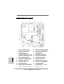 2
2
-
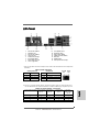 3
3
-
 4
4
-
 5
5
-
 6
6
-
 7
7
-
 8
8
-
 9
9
-
 10
10
-
 11
11
-
 12
12
-
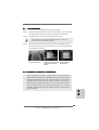 13
13
-
 14
14
-
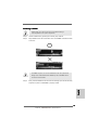 15
15
-
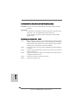 16
16
-
 17
17
-
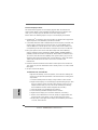 18
18
-
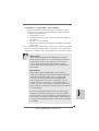 19
19
-
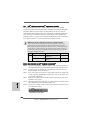 20
20
-
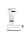 21
21
-
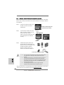 22
22
-
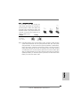 23
23
-
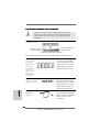 24
24
-
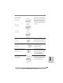 25
25
-
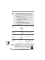 26
26
-
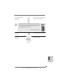 27
27
-
 28
28
-
 29
29
-
 30
30
-
 31
31
-
 32
32
-
 33
33
-
 34
34
-
 35
35
-
 36
36
-
 37
37
-
 38
38
-
 39
39
-
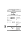 40
40
-
 41
41
-
 42
42
-
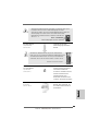 43
43
-
 44
44
-
 45
45
-
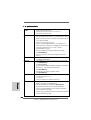 46
46
-
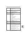 47
47
-
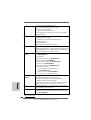 48
48
-
 49
49
-
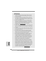 50
50
-
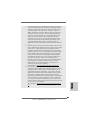 51
51
-
 52
52
-
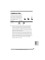 53
53
-
 54
54
-
 55
55
-
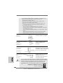 56
56
-
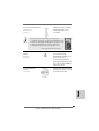 57
57
-
 58
58
-
 59
59
-
 60
60
-
 61
61
-
 62
62
-
 63
63
-
 64
64
-
 65
65
-
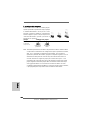 66
66
-
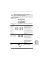 67
67
-
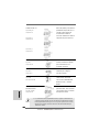 68
68
-
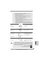 69
69
-
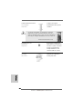 70
70
-
 71
71
-
 72
72
-
 73
73
-
 74
74
-
 75
75
-
 76
76
-
 77
77
-
 78
78
-
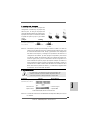 79
79
-
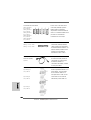 80
80
-
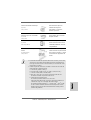 81
81
-
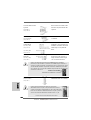 82
82
-
 83
83
-
 84
84
-
 85
85
-
 86
86
-
 87
87
-
 88
88
-
 89
89
-
 90
90
-
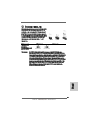 91
91
-
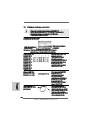 92
92
-
 93
93
-
 94
94
-
 95
95
-
 96
96
-
 97
97
-
 98
98
-
 99
99
-
 100
100
-
 101
101
-
 102
102
-
 103
103
-
 104
104
-
 105
105
-
 106
106
-
 107
107
-
 108
108
-
 109
109
-
 110
110
-
 111
111
-
 112
112
-
 113
113
-
 114
114
-
 115
115
-
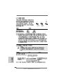 116
116
-
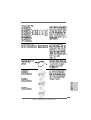 117
117
-
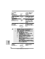 118
118
-
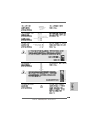 119
119
-
 120
120
-
 121
121
-
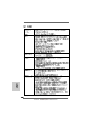 122
122
-
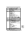 123
123
-
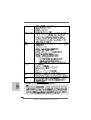 124
124
-
 125
125
-
 126
126
-
 127
127
-
 128
128
-
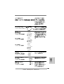 129
129
-
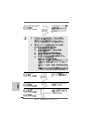 130
130
-
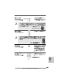 131
131
-
 132
132
-
 133
133
-
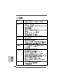 134
134
-
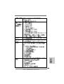 135
135
-
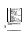 136
136
-
 137
137
-
 138
138
-
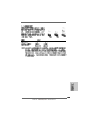 139
139
-
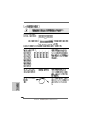 140
140
-
 141
141
-
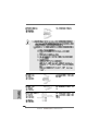 142
142
-
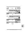 143
143
-
 144
144
-
 145
145
-
 146
146
-
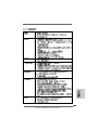 147
147
-
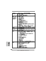 148
148
-
 149
149
-
 150
150
-
 151
151
-
 152
152
-
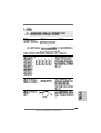 153
153
-
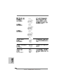 154
154
-
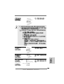 155
155
-
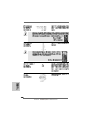 156
156
-
 157
157
-
 158
158


ASROCK 880GMH-U3S3 El manual del propietario
- Categoría
- Placas base
- Tipo
- El manual del propietario
- Este manual también es adecuado para
en otros idiomas
- français: ASROCK 880GMH-U3S3 Le manuel du propriétaire
- italiano: ASROCK 880GMH-U3S3 Manuale del proprietario
- English: ASROCK 880GMH-U3S3 Owner's manual
- Deutsch: ASROCK 880GMH-U3S3 Bedienungsanleitung
Artículos relacionados
-
ASROCK B85iCafe4 El manual del propietario
-
ASROCK H81M Especificación
-
ASROCK Z87iCafe4 Guía de inicio rápido
-
ASROCK H87M El manual del propietario
-
ASROCK 890FX Deluxe3 El manual del propietario
-
ASROCK H61ICAFE El manual del propietario
-
ASROCK H61DE-S3 El manual del propietario
-
ASROCK AD525PV3 Manual de usuario
-
-
ASROCK 880GMH USB3 R2.0 El manual del propietario