ASROCK AD525PV3 Manual de usuario
- Categoría
- Placas base
- Tipo
- Manual de usuario
Este manual también es adecuado para

11
11
1
ASRock AD525PV3 / AD425PV3 Motherboard
EnglishEnglish
EnglishEnglish
English
Copyright Notice:Copyright Notice:
Copyright Notice:Copyright Notice:
Copyright Notice:
No part of this installation guide may be reproduced, transcribed, transmitted, or trans-
lated in any language, in any form or by any means, except duplication of documen-
tation by the purchaser for backup purpose, without written consent of ASRock Inc.
Products and corporate names appearing in this guide may or may not be registered
trademarks or copyrights of their respective companies, and are used only for identifica-
tion or explanation and to the owners’ benefit, without intent to infringe.
Disclaimer:Disclaimer:
Disclaimer:Disclaimer:
Disclaimer:
Specifications and information contained in this guide are furnished for informational
use only and subject to change without notice, and should not be constructed as a
commitment by ASRock. ASRock assumes no responsibility for any errors or omissions
that may appear in this guide.
With respect to the contents of this guide, ASRock does not provide warranty of any kind,
either expressed or implied, including but not limited to the implied warranties or
conditions of merchantability or fitness for a particular purpose. In no event shall
ASRock, its directors, officers, employees, or agents be liable for any indirect, special,
incidental, or consequential damages (including damages for loss of profits, loss of
business, loss of data, interruption of business and the like), even if ASRock has been
advised of the possibility of such damages arising from any defect or error in the guide
or product.
This device complies with Part 15 of the FCC Rules. Operation is subject to the
following two conditions:
(1) this device may not cause harmful interference, and
(2) this device must accept any interference received, including interference that
may cause undesired operation.
Published November 2010
Copyright©2010 ASRock INC. All rights reserved.
CALIFORNIA, USA ONLY
The Lithium battery adopted on this motherboard contains Perchlorate, a toxic
substance controlled in Perchlorate Best Management Practices (BMP) regulations
passed by the California Legislature. When you discard the Lithium battery in
California, USA, please follow the related regulations in advance.
“Perchlorate Material-special handling may apply, see
www.dtsc.ca.gov/hazardouswaste/perchlorate”
ASRock Website: http://www.asrock.com

22
22
2
ASRock AD525PV3 / AD425PV3 Motherboard
EnglishEnglish
EnglishEnglish
English
Motherboard LayoutMotherboard Layout
Motherboard LayoutMotherboard Layout
Motherboard Layout
1 CPU Fan Connector (CPU_FAN1) 9 USB 2.0 Header (USB6_7, Blue)
2 CPU Fan 10 USB 2.0 Header (USB4_5, Blue)
3 CPU Heatsink 11 System Panel Header (PANEL1, White)
4 2 x 240-pin DDR3 DIMM Slots 12 Chassis Speaker Header (SPEAKER 1, White)
(Dual Channel: DDR3_A1, DDR3_A2; Blue) 13 BIOS SPI Chip
5 ATX Power Connector (ATXPWR1) 14 PCI Slot (PCI1)
6 Chassis Fan Connector (CHA_FAN1) 15 Front Panel Audio Header
7 Secondary SATAII Connector (SATAII_2; Blue) (HD_AUDIO1, White)
8 Primary SATAII Connector (SATAII_1; Blue) 16 South Bridge Controller

33
33
3
ASRock AD525PV3 / AD425PV3 Motherboard
EnglishEnglish
EnglishEnglish
English
I/O PI/O P
I/O PI/O P
I/O P
anelanel
anelanel
anel
1 PS/2 Mouse Port (Green) 7 USB 2.0 Ports (USB01)
2 Parallel Port 8 USB 2.0 Ports (USB23)
3 RJ-45 Port 9 VGA Port
4 Line In (Light Blue) 10 COM Port
5 Line Out (Lime) 11 PS/2 Keyboard Port (Purple)
6 Microphone (Pink)
LAN Port
ACT/LINK
LED
SPEED
LED
* There are two LED next to the LAN port. Please refer to the table below for the LAN port LED
indications.
LAN Port LED Indications
Activity/Link LED SPEED LED
Status Description Status Description
Off No Activity Off 10Mbps connection
Blinking Data Activity Orange 100Mbps connection
Green 1Gbps connection
** To enable Multi-Streaming function, you need to connect a front panel audio cable to the front
panel audio header. Please refer to below steps for the software setting of Multi-Streaming.
For Windows
®
XP:
After restarting your computer, you will find “Mixer” tool on your system. Please select “Mixer
ToolBox” , click “Enable playback multi-streaming”, and click “ok”. Choose “2CH” or
“4CH” and then you are allowed to select “Realtek HDA Primary output” to use Rear Speaker
and Front Speaker, or select “Realtek HDA Audio 2nd output” to use front panel audio. Then
reboot your system.
For Windows
®
7 / Vista
TM
:
After restarting your computer, please double-click “Realtek HD Audio Manager” on the
system tray. Set “Speaker Configuration” to “Quadraphonic” or “Stereo”. Click “Device
advanced settings”, choose “Make front and rear output devices playbacks two different audio
streams simultaneously”, and click “ok”. Then reboot your system.

44
44
4
ASRock AD525PV3 / AD425PV3 Motherboard
EnglishEnglish
EnglishEnglish
English
1. Introduction1. Introduction
1. Introduction1. Introduction
1. Introduction
Thank you for purchasing ASRock AD525PV3 / AD425PV3 motherboard, a reliable
motherboard produced under ASRock’s consistently stringent quality control. It de-
livers excellent performance with robust design conforming to ASRock’s commit-
ment to quality and endurance.
This Quick Installation Guide contains introduction of the motherboard and step-by-
step installation guide. More detailed information of the motherboard can be found in
the user manual presented in the Support CD.
Because the motherboard specifications and the BIOS software might
be updated, the content of this manual will be subject to change without
notice. In case any modifications of this manual occur, the updated
version will be available on ASRock website without further notice. You
may find the latest VGA cards and CPU support lists on ASRock website
as well. ASRock website http://www.asrock.com
If you require technical support related to this motherboard, please visit
our website for specific information about the model you are using.
www.asrock.com/support/index.asp
1.1 Package Contents1.1 Package Contents
1.1 Package Contents1.1 Package Contents
1.1 Package Contents
ASRock AD525PV3 / AD425PV3 Motherboard
(Mini-ITX Form Factor: 6.7-in x 6.7-in, 17.0 cm x 17.0 cm)
One Bundled Intel
®
Dual-Core Atom
TM
Processor D525 (AD525PV3)
One Bundled Intel
®
Atom
TM
Processor D425 (AD425PV3)
ASRock AD525PV3 / AD425PV3 Quick Installation Guide
ASRock AD525PV3 / AD425PV3 Support CD
Two Serial ATA (SATA) Data Cables (Optional)
One I/O Panel Shield

55
55
5
ASRock AD525PV3 / AD425PV3 Motherboard
EnglishEnglish
EnglishEnglish
English
1.21.2
1.21.2
1.2
SpecificationsSpecifications
SpecificationsSpecifications
Specifications
Platform - Mini-ITX Form Factor: 6.7-in x 6.7-in, 17.0 cm x 17.0 cm
- All Solid Capacitor design (100% Japan-made high-quality
Conductive Polymer Capacitors) (AD525PV3)
- Solid Capacitor for CPU power (AD425PV3)
CPU - Intel
®
Dual-Core Atom
TM
Processor D525 (AD525PV3)
- Intel
®
Atom
TM
Processor D425 (AD425PV3)
- Supports Hyper-Threading Technology (see CAUTION 1)
- Supports Untied Overclocking Technology (see CAUTION 2)
- Supports EM64T CPU
Chipset - Southbridge: Intel
®
NM10 Express
Memory - 2 x DDR3 DIMM slots
- Supports DDR3 800 non-ECC, un-buffered memory
- Max. capacity of system memory: 8GB (see CAUTION 3)
Expansion Slot - 1 x PCI slot
Graphics - Intel
®
Graphics Media Accelerator 3150
- Pixel Shader 2.0, DirectX 9.0
- Max. shared memory 384MB (see CAUTION 4)
- Supports D-Sub with max. resolution up to 2048x1536
@ 60Hz
Audio - 5.1 CH HD Audio (Realtek ALC662 Audio Codec)
LAN - PCIE x1 Gigabit LAN 10/100/1000 Mb/s
- Atheros
®
AR8151
- Supports Wake-On-LAN
Rear Panel I/O I/O Panel
- 1 x PS/2 Mouse Port
- 1 x PS/2 Keyboard Port
- 1 x Parallel Port (ECP/EPP Support)
- 1 x Serial Port: COM1
- 1 x VGA Port
- 4 x Ready-to-Use USB 2.0 Ports
- 1 x RJ-45 LAN Port with LED (ACT/LINK LED and SPEED LED)
- HD Audio Jack: Line in / Front Speaker / Microphone
Connector - 2 x SATAII 3.0 Gb/s connectors, support NCQ, AHCI and Hot
Plug functions (see CAUTION 5)
- CPU/Chassis FAN connector
- 24 pin ATX power connector
- Front panel audio connector
- 2 x USB 2.0 headers (support 4 USB 2.0 ports)
(see CAUTION 6)

66
66
6
ASRock AD525PV3 / AD425PV3 Motherboard
EnglishEnglish
EnglishEnglish
English
BIOS Feature - 4Mb AMI BIOS
- AMI Legal BIOS
- Supports “Plug and Play”
- ACPI 1.1 Compliance Wake Up Events
- Supports jumperfree
- AMBIOS 2.3.1 Support
- VCCM, SB Voltage Multi-adjustment
Support CD - Drivers, Utilities, AntiVirus Software (Trial Version),
ASRock Software Suite (CyberLink DVD Suite - OEM and
Trial; Creative Sound Blaster X-Fi MB - Trial)
Unique Feature - ASRock OC Tuner (see CAUTION 7)
- Instant Boot
- ASRock Instant Flash (see CAUTION 8)
- ASRock OC DNA (see CAUTION 9)
- ASRock AIWI (see CAUTION 10)
- ASRock APP Charger (see CAUTION 11)
- SmartView
- Hybrid Booster:
- CPU Frequency Stepless Control (see CAUTION 12)
- ASRock U-COP (see CAUTION 13)
- Boot Failure Guard (B.F.G.)
Hardware - CPU Temperature Sensing
Monitor - Chassis Temperature Sensing
- CPU Fan Tachometer
- Chassis Fan Tachometer
- CPU Quiet Fan
- Voltage Monitoring: +12V, +5V, +3.3V, Vcore
OS - Microsoft
®
Windows
®
7 / 7 64-bit / Vista
TM
/ Vista
TM
64-bit /
XP / XP 64-bit compliant
Certifications - FCC, CE, WHQL
- ErP/EuP Ready (ErP/EuP ready power supply is required)
(see CAUTION 14)
* For detailed product information, please visit our website: http://www.asrock.com
WARNING
Please realize that there is a certain risk involved with overclocking, including adjusting
the setting in the BIOS, applying Untied Overclocking Technology, or using the third-
party overclocking tools. Overclocking may affect your system stability, or even
cause damage to the components and devices of your system. It should be done at
your own risk and expense. We are not responsible for possible damage caused by
overclocking.

77
77
7
ASRock AD525PV3 / AD425PV3 Motherboard
EnglishEnglish
EnglishEnglish
English
CAUTION!
1. About the setting of “Hyper Threading Technology”, please check page 31
of “User Manual” in the support CD.
2. This motherboard supports Untied Overclocking Technology. Please read “Un-
tied Overclocking Technology” on page 16 for details.
3. Due to the chipset limitation, the actual memory size may be less than
4GB for the reservation for system usage under Windows
®
OS.
4. The maximum shared memory size is defined by the chipset vendor and
is subject to change. Please check Intel
®
website for the latest information.
5. Before installing SATAII hard disk to SATAII connector, please read the “SATAII
Hard Disk Setup Guide” on page 17 of “User Manual” in the support CD to
adjust your SATAII hard disk drive to SATAII mode. You can also connect SATA
hard disk to SATAII connector directly.
6. Power Management for USB 2.0 works fine under Microsoft
®
Windows
®
7
64-bit / 7 / Vista
TM
64-bit / Vista
TM
/ XP 64-bit / XP SP1 or SP2.
7. It is a user-friendly ASRock overclocking tool which allows you to surveil
your system by hardware monitor function and overclock your hardware
devices to get the best system performance under Windows
®
environment.
Please visit our website for the operation procedures of ASRock OC
Tuner. ASRock website: http://www.asrock.com
8. ASRock Instant Flash is a BIOS flash utility embedded in Flash ROM.
This convenient BIOS update tool allows you to update system BIOS
without entering operating systems first like MS-DOS or Windows
®
. With
this utility, you can press <F6> key during the POST or press <F2> key to
BIOS setup menu to access ASRock Instant Flash. Just launch this tool
and save the new BIOS file to your USB flash drive, floppy disk or hard
drive, then you can update your BIOS only in a few clicks without prepar-
ing an additional floppy diskette or other complicated flash utility. Please
be noted that the USB flash drive or hard drive must use FAT32/16/12 file
system.
9. The software name itself – OC DNA literally tells you what it is capable of.
OC DNA, an exclusive utility developed by ASRock, provides a conve-
nient way for the user to record the OC settings and share with others. It
helps you to save your overclocking record under the operating system
and simplifies the complicated recording process of overclocking settings.
With OC DNA, you can save your OC settings as a profile and share with
your friends! Your friends then can load the OC profile to their own system
to get the same OC settings as yours! Please be noticed that the OC
profile can only be shared and worked on the same motherboard.
10. To experience intuitive motion controlled games is no longer only available
at Wii. ASRock AIWI utility introduces a new way of PC gaming operation.
ASRock AIWI is the world's first utility to turn your iPhone/iPod touch as
a game joystick to control your PC games. All you have to do is just to
install the ASRock AIWI utility either from ASRock official website or
ASRock software support CD to your motherboard, and also download the
free AIWI Lite from App store to your iPhone/iPod touch. Connecting your

88
88
8
ASRock AD525PV3 / AD425PV3 Motherboard
EnglishEnglish
EnglishEnglish
English
PC and apple devices via Bluetooth or WiFi networks, then you can start
experiencing the exciting motion controlled games. Also, please do not
forget to pay attention to ASRock official website regularly, we will
continuously provide you the most up-do-date supported games!
ASRock website: http://www.asrock.com/Feature/Aiwi/index.asp
11. If you desire a faster, less restricted way of charging your Apple devices,
such as iPhone/iPod/iPad Touch, ASRock has prepared a wonderful
solution for you - ASRock APP Charger. Simply installing the APP Charger
driver, it makes your iPhone charged much quickly from your computer
and up to 40% faster than before. ASRock APP Charger allows you to
quickly charge many Apple devices simultaneously and even supports
continuous charging when your PC enters into Standby mode (S1), Sus-
pend to RAM (S3), hibernation mode (S4) or power off (S5). With APP
Charger driver installed, you can easily enjoy the marvelous charging
experience than ever.
ASRock website: http://www.asrock.com/Feature/AppCharger/index.asp
12. Although this motherboard offers stepless control, it is not recommended
to perform over-clocking. Frequencies other than the recommended CPU
bus frequencies may cause the instability of the system or damage the
CPU.
13. While CPU overheat is detected, the system will automatically shutdown.
Before you resume the system, please check if the CPU fan on the
motherboard functions properly and unplug the power cord, then plug it
back again. To improve heat dissipation, remember to spray thermal
grease between the CPU and the heatsink when you install the PC system.
14. EuP, stands for Energy Using Product, was a provision regulated by
European Union to define the power consumption for the completed system.
According to EuP, the total AC power of the completed system shall be
under 1.00W in off mode condition. To meet EuP standard, an EuP ready
motherboard and an EuP ready power supply are required. According to
Intel’s suggestion, the EuP ready power supply must meet the standard of
5v standby power efficiency is higher than 50% under 100 mA current
consumption. For EuP ready power supply selection, we recommend you
checking with the power supply manufacturer for more details.

99
99
9
ASRock AD525PV3 / AD425PV3 Motherboard
EnglishEnglish
EnglishEnglish
English
2. Installation2. Installation
2. Installation2. Installation
2. Installation
AD525PV3 / AD425PV3 is a Mini-ITX form factor (6.7" x 6.7", 17.0 x 17.0 cm)
motherboard. Before you install the motherboard, study the configuration of your
chassis to ensure that the motherboard fits into it.
Make sure to unplug the power cord before installing or removing the
motherboard. Failure to do so may cause physical injuries to you and
damages to motherboard components.
2.1 Screw Holes2.1 Screw Holes
2.1 Screw Holes2.1 Screw Holes
2.1 Screw Holes
Place screws into the holes indicated by circles to secure the motherboard to the
chassis.
Do not over-tighten the screws! Doing so may damage the motherboard.
2.2 Pre-installation Precautions2.2 Pre-installation Precautions
2.2 Pre-installation Precautions2.2 Pre-installation Precautions
2.2 Pre-installation Precautions
Take note of the following precautions before you install motherboard components
or change any motherboard settings.
1. Unplug the power cord from the wall socket before touching any component.
2. To avoid damaging the motherboard components due to static electricity, NEVER
place your motherboard directly on the carpet or the like. Also remember to use
a grounded wrist strap or touch a safety grounded object before you handle
components.
3. Hold components by the edges and do not touch the ICs.
4. Whenever you uninstall any component, place it on a grounded antistatic pad or
in the bag that comes with the component.
Before you install or remove any component, ensure that the power is
switched off or the power cord is detached from the power supply.
Failure to do so may cause severe damage to the motherboard, peripherals,
and/or components.

1010
1010
10
ASRock AD525PV3 / AD425PV3 Motherboard
EnglishEnglish
EnglishEnglish
English
2.3 Installation of Memory Modules (DIMM)2.3 Installation of Memory Modules (DIMM)
2.3 Installation of Memory Modules (DIMM)2.3 Installation of Memory Modules (DIMM)
2.3 Installation of Memory Modules (DIMM)
AD525PV3 / AD425PV3 motherboard provides two 240-pin DDR3 (Double Data
Rate 3) DIMM slots.
It is not allowed to install a DDR or DDR2 memory module into DDR3
slot; otherwise, this motherboard and DIMM may be damaged.
Installing a DIMMInstalling a DIMM
Installing a DIMMInstalling a DIMM
Installing a DIMM
Please make sure to disconnect power supply before adding or
removing DIMMs or the system components.
Step 1. Unlock a DIMM slot by pressing the retaining clips outward.
Step 2. Align a DIMM on the slot such that the notch on the DIMM matches the break
on the slot.
The DIMM only fits in one correct orientation. It will cause permanent
damage to the motherboard and the DIMM if you force the DIMM into the
slot at incorrect orientation.
Step 3. Firmly insert the DIMM into the slot until the retaining clips at both ends fully
snap back in place and the DIMM is properly seated.

1111
1111
11
ASRock AD525PV3 / AD425PV3 Motherboard
EnglishEnglish
EnglishEnglish
English
2.4 Expansion Slot (PCI Slot)2.4 Expansion Slot (PCI Slot)
2.4 Expansion Slot (PCI Slot)2.4 Expansion Slot (PCI Slot)
2.4 Expansion Slot (PCI Slot)
There is 1 PCI slot on this motherboard.
PCI slot: PCI slot is used to install expansion cards that have the 32-bit PCI interface.
Installing an expansion cardInstalling an expansion card
Installing an expansion cardInstalling an expansion card
Installing an expansion card
Step 1. Before installing the expansion card, please make sure that the power
supply is switched off or the power cord is unplugged. Please read the
documentation of the expansion card and make necessary hardware
settings for the card before you start the installation.
Step 2. Remove the bracket facing the slot that you intend to use. Keep the screws
for later use.
Step 3. Align the card connector with the slot and press firmly until the card is
completely seated on the slot.
Step 4. Fasten the card to the chassis with screws.

1212
1212
12
ASRock AD525PV3 / AD425PV3 Motherboard
EnglishEnglish
EnglishEnglish
English
Front Panel Audio Header This is an interface for front
(9-pin HD_AUDIO1) panel audio cable that allows
(see p.2 No. 15) convenient connection and
control of audio devices.
USB 2.0 Headers Besides four default USB 2.0
(9-pin USB6_7) ports on the I/O panel, there are
(see p.2 No. 9) two USB 2.0 headers on this
motherboard. Each USB 2.0
header cansupport two USB
2.0 ports.
(9-pin USB4_5)
(see p.2 No. 10)
2.5 Onboard Headers and Connectors2.5 Onboard Headers and Connectors
2.5 Onboard Headers and Connectors2.5 Onboard Headers and Connectors
2.5 Onboard Headers and Connectors
Onboard headers and connectors are NOT jumpers. Do NOT place
jumper caps over these headers and connectors. Placing jumper caps
over the headers and connectors will cause permanent damage of the
motherboard!
Serial ATAII Connectors These Serial ATAII (SATAII)
(SATAII_1: see p.2, No. 8) connectors support SATAII
(SATAII_2: see p.2, No. 7) or SATA hard disk for internal
storage devices. The current
SATAII interface allows up to
3.0 Gb/s data transfer rate.
Serial ATA (SATA) Either end of the SATA data cable
Data Cable can be connected to the SATA /
(Optional) SATAII hard disk or the SATAII
connector on the motherboard.
SATAII_2
SATAII_1

1313
1313
13
ASRock AD525PV3 / AD425PV3 Motherboard
1. High Definition Audio supports Jack Sensing, but the panel wire on
the chassis must support HDA to function correctly. Please follow the
instruction in our manual and chassis manual to install your system.
2. If you use AC’97 audio panel, please install it to the front panel audio
header as below:
A. Connect Mic_IN (MIC) to MIC2_L.
B. Connect Audio_R (RIN) to OUT2_R and Audio_L (LIN) to OUT2_L.
C. Connect Ground (GND) to Ground (GND).
D. MIC_RET and OUT_RET are for HD audio panel only. You don’t
need to connect them for AC’97 audio panel.
System Panel Header This header accommodates
(9-pin PANEL1) several system front panel
(see p.2 No. 11) functions.
Chassis Speaker Header Please connect the chassis
(4-pin SPEAKER 1) speaker to this header.
(see p.2 No. 12)
Chassis Fan Connector Please connect a chassis fan
(3-pin CHA_FAN1) cable to this connector and
(see p.2 No. 6) match the black wire to the
ground pin.
CPU Fan Connector Please connect a CPU fan cable
(3-pin CPU_FAN1) to this connector and match
(see p.2 No. 1) the black wire to the ground pin.
EnglishEnglish
EnglishEnglish
English
20-Pin ATX Power Supply Installation
ATX Power Connector Please connect an ATX power
(24-pin ATXPWR1) supply to this connector.
(see p.2, No. 5)
Though this motherboard provides 24-pin ATX power connector,
it can still work if you adopt a traditional 20-pin ATX power supply.
To use the 20-pin ATX power supply, please plug your power
supply along with Pin 1 and Pin 13.
12
1
24
13
12
1
24
13

1414
1414
14
ASRock AD525PV3 / AD425PV3 Motherboard
EnglishEnglish
EnglishEnglish
English
2.7 Hot Plug F2.7 Hot Plug F
2.7 Hot Plug F2.7 Hot Plug F
2.7 Hot Plug F
unction for SAunction for SA
unction for SAunction for SA
unction for SA
TT
TT
T
A / SAA / SA
A / SAA / SA
A / SA
TT
TT
T
AII HDDsAII HDDs
AII HDDsAII HDDs
AII HDDs
This motherboard supports Hot Plug function for SATA / SATAII Devices in AHCI
mode. Intel
®
NM10 Express south bridge chipset provides hardware support for
Advanced Host controller Interface (AHCI), a new programming interface for SATA
host controllers developed thru a joint industry effort. AHCI also provides usability
enhancements such as Hot Plug.
NOTE
What is Hot Plug Function?
If the SATA / SATAII HDDs are NOT set for RAID configuration, it is called
“Hot Plug” for the action to insert and remove the SATA / SATAII HDDs
while the system is still power-on and in working condition.
However, please note that it cannot perform Hot Plug if the OS has been
installed into the SATA / SATAII HDD.
2.62.6
2.62.6
2.6
Serial ASerial A
Serial ASerial A
Serial A
TT
TT
T
A (SAA (SA
A (SAA (SA
A (SA
TT
TT
T
A) / Serial AA) / Serial A
A) / Serial AA) / Serial A
A) / Serial A
TT
TT
T
AII (SAAII (SA
AII (SAAII (SA
AII (SA
TT
TT
T
AII) Hard DisksAII) Hard Disks
AII) Hard DisksAII) Hard Disks
AII) Hard Disks
InstallationInstallation
InstallationInstallation
Installation
This motherboard adopts Intel
®
NM10 Express south bridge chipset that supports
Serial ATA (SATA) / Serial ATAII (SATAII) hard disks. You may install SATA / SATAII
hard disks on this motherboard for internal storage devices. This section will
guide you to install the SATA / SATAII hard disks.
STEP 1: Install the SATA / SATAII hard disks into the drive bays of your chassis.
STEP 2: Connect the SATA power cable to the SATA / SATAII hard disk.
STEP 3: Connect one end of the SATA data cable to the motherboard’s SATAII
connector.
STEP 4: Connect the other end of the SATA data cable to the SATA / SATAII hard
disk.

1515
1515
15
ASRock AD525PV3 / AD425PV3 Motherboard
EnglishEnglish
EnglishEnglish
English
2.82.8
2.82.8
2.8
Driver Installation GuideDriver Installation Guide
Driver Installation GuideDriver Installation Guide
Driver Installation Guide
To install the drivers to your system, please insert the support CD to your optical
drive first. Then, the drivers compatible to your system can be auto-detected and
listed on the support CD driver page. Please follow the order from up to bottom
side to install those required drivers. Therefore, the drivers you install can work
properly.
2.92.9
2.92.9
2.9
Installing WindowsInstalling Windows
Installing WindowsInstalling Windows
Installing Windows
®
7 / 7 64-bit / Vista 7 / 7 64-bit / Vista
7 / 7 64-bit / Vista 7 / 7 64-bit / Vista
7 / 7 64-bit / Vista
TM TM
TM TM
TM
//
//
/
VistaVista
VistaVista
Vista
TM TM
TM TM
TM
64-bit / XP / XP 64-bit Without RAID Functions64-bit / XP / XP 64-bit Without RAID Functions
64-bit / XP / XP 64-bit Without RAID Functions64-bit / XP / XP 64-bit Without RAID Functions
64-bit / XP / XP 64-bit Without RAID Functions
If you want to install Windows
®
7 / 7 64-bit / Vista
TM
/ Vista
TM
64-bit / XP / XP 64-bit OS
on your SATA / SATAII HDDs without RAID functions, please follow below procedures
according to the OS you install.
2.9.1 Installing Windows2.9.1 Installing Windows
2.9.1 Installing Windows2.9.1 Installing Windows
2.9.1 Installing Windows
®
XP / XP 64-bit Without RAID XP / XP 64-bit Without RAID
XP / XP 64-bit Without RAID XP / XP 64-bit Without RAID
XP / XP 64-bit Without RAID
Functions Functions
Functions Functions
Functions
If you want to install Windows
®
XP / XP 64-bit OS on your SATA / SATAII HDDs
without RAID functions, please follow below steps.
STEP 1: Set up BIOS.
A. Enter BIOS SETUP UTILITY Advanced screen Storage Configuration.
B. Set the option “SATA Operation Mode” to [IDE].
STEP 2: Install Windows
®
XP / XP 64-bit OS on your system.
Using SATA / SATAII HDDs without NCQ function
2.9.2 Installing Windows2.9.2 Installing Windows
2.9.2 Installing Windows2.9.2 Installing Windows
2.9.2 Installing Windows
®
7 / 7 64-bit / Vista 7 / 7 64-bit / Vista
7 / 7 64-bit / Vista 7 / 7 64-bit / Vista
7 / 7 64-bit / Vista
TM TM
TM TM
TM
//
//
/
Vista Vista
Vista Vista
Vista
TM TM
TM TM
TM
64-bit Without RAID Functions64-bit Without RAID Functions
64-bit Without RAID Functions64-bit Without RAID Functions
64-bit Without RAID Functions
If you want to install Windows
®
7 / 7 64-bit / Vista
TM
/ Vista
TM
64-bit OS on your SATA
/ SATAII HDDs without RAID functions, please follow below steps.
Using SATA / SATAII HDDs without NCQ function
STEP 1: Set up BIOS.
A. Enter BIOS SETUP UTILITY Advanced screen Storage Configuration.
B. Set the option “SATA Operation Mode” to [IDE].
STEP 2: Install Windows
®
7 / 7 64-bit / Vista
TM
/ Vista
TM
64-bit OS on your
system.
AHCI mode is not supported under Windows
®
XP / XP 64-bit OS.

1616
1616
16
ASRock AD525PV3 / AD425PV3 Motherboard
Using SATA / SATAII HDDs with NCQ function
STEP 1: Set Up BIOS.
A. Enter BIOS SETUP UTILITY Advanced screen Storage Configuration.
B. Set the option “SATA Operation Mode” to [AHCI].
STEP 2: Install Windows
®
7 / 7 64-bit / Vista
TM
/ Vista
TM
64-bit OS on your
system.
2.102.10
2.102.10
2.10
Untied Overclocking TUntied Overclocking T
Untied Overclocking TUntied Overclocking T
Untied Overclocking T
echnologyechnology
echnologyechnology
echnology
This motherboard supports Untied Overclocking Technology, which means during
overclocking, FSB enjoys better margin due to fixed PCI bus. Before you enable
Untied Overclocking function, please enter “Overclock Mode” option of BIOS setup to
set the selection from [Auto] to [Manual]. Therefore, CPU FSB is untied during
overclocking, but PCI buse is in the fixed mode so that FSB can operate under a more
stable overclocking environment.
Please refer to the warning on page 6 for the possible overclocking risk
before you apply Untied Overclocking Technology.
EnglishEnglish
EnglishEnglish
English

1717
1717
17
ASRock AD525PV3 / AD425PV3 Motherboard
3. BIOS Information3. BIOS Information
3. BIOS Information3. BIOS Information
3. BIOS Information
The Flash Memory on the motherboard stores BIOS Setup Utility. When you start up
the computer, please press <F2> during the Power-On-Self-Test (POST) to enter
BIOS Setup utility; otherwise, POST continues with its test routines. If you wish to
enter BIOS Setup after POST, please restart the system by pressing <Ctl> + <Alt> +
<Delete>, or pressing the reset button on the system chassis. The BIOS Setup pro-
gram is designed to be user-friendly. It is a menu-driven program, which allows you to
scroll through its various sub-menus and to select among the predetermined choices.
For the detailed information about BIOS Setup, please refer to the User Manual (PDF
file) contained in the Support CD.
4. Sof4. Sof
4. Sof4. Sof
4. Sof
tware Supportware Suppor
tware Supportware Suppor
tware Suppor
t CD informationt CD information
t CD informationt CD information
t CD information
This motherboard supports various Microsoft
®
Windows
®
operating systems: 7 /
7 64-bit / Vista
TM
/ Vista
TM
64-bit / XP / XP 64-bit. The Support CD that came with the
motherboard contains necessary drivers and useful utilities that will enhance
motherboard features. To begin using the Support CD, insert the CD into your CD-
ROM drive. It will display the Main Menu automatically if “AUTORUN” is enabled in
your computer. If the Main Menu does not appear automatically, locate and double-
click on the file “ASSETUP.EXE” from the BIN folder in the Support CD to display the
menus.
EnglishEnglish
EnglishEnglish
English

1818
1818
18
ASRock AD525PV3 / AD425PV3 Motherboard
DeutschDeutsch
DeutschDeutsch
Deutsch
1. Einführung1. Einführung
1. Einführung1. Einführung
1. Einführung
Wir danken Ihnen für den Kauf des ASRock AD525PV3 / AD425PV3 Motherboard,
ein zuverlässiges Produkt, welches unter den ständigen, strengen Qualitätskontrollen
von ASRock gefertigt wurde. Es bietet Ihnen exzellente Leistung und robustes Design,
gemäß der Verpflichtung von ASRock zu Qualität und Halbarkeit.
Diese Schnellinstallationsanleitung führt in das Motherboard und die schrittweise
Installation ein. Details über das Motherboard finden Sie in der
Bedienungsanleitung auf der Support-CD.
Da sich Motherboard-Spezifikationen und BIOS-Software verändern
können, kann der Inhalt dieses Handbuches ebenfalls jederzeit geändert
werden. Für den Fall, dass sich Änderungen an diesem Handbuch
ergeben, wird eine neue Version auf der ASRock-Website, ohne weitere
Ankündigung, verfügbar sein. Die neuesten Grafikkarten und unterstützten
CPUs sind auch auf der ASRock-Website aufgelistet.
ASRock-Website: http://www.asrock.com
Wenn Sie technische Unterstützung zu Ihrem Motherboard oder spezifische
Informationen zu Ihrem Modell benötigen, besuchen Sie bitte unsere
Webseite:
www.asrock.com/support/index.asp
1.1 Kartoninhalt
ASRock AD525PV3 / AD425PV3 Motherboard
(Mini-ITX-Formfaktor: 17.0 cm x 17.1 cm; 6.7 Zoll x 6.7 Zoll)
Ein mitgelieferter Intel
®
Dual-Core-Atom
TM
-Prozessor D525 (AD525PV3)
Eine mitgelieferter Intel
®
Atom
TM
-Prozessor D425 (AD425PV3)
ASRock AD525PV3 / AD425PV3 Schnellinstallationsanleitung
ASRock AD525PV3 / AD425PV3_ Support-CD
Zwei Seriell-ATA- (SATA) Datenkabel (Option)
Ein I/O Shield

1919
1919
19
ASRock AD525PV3 / AD425PV3 Motherboard
1.21.2
1.21.2
1.2
SpezifikationenSpezifikationen
SpezifikationenSpezifikationen
Spezifikationen
Plattform - Mini-ITX-Formfaktor: 17.0 cm x 17.1 cm; 6.7 Zoll x 6.7 Zoll
- Alle Feste Kondensatordesign (100% in Japan gefertigte,
erstklassige leitfähige Polymer-Kondensatoren) (AD525PV3)
- Festkondensator für CPU-Leistung (AD425PV3)
CPU - Intel
®
Dual-Core Atom
TM
-Prozessor D525 (AD525PV3)
- Intel
®
Atom
TM
-Prozessor D425 (AD425PV3)
- Unterstützt Hyper-Threading-Technologie
(siehe VORSICHT 1)
- Unterstützt Untied-Übertaktungstechnologie
(siehe VORSICHT 2)
- Unterstützt EM64T-CPU
Chipsatz - Southbridge: Intel
®
NM10 Express
Speicher - 2 x Steckplätze für DDR3
- Unterstützt DDR3 800 non-ECC, ungepufferter Speicher
- Max. Kapazität des Systemspeichers: 8GB
(siehe VORSICHT 3)
Erweiterungs- - 1 x PCI -Steckplätze
steckplätze
Onboard-VGA - Intel
®
Graphics Media Accelerator 3150
- Pixel Shader 2.0, DX9.0 VGA
- Maximal gemeinsam genutzter Speicher 384MB
(siehe VORSICHT 4)
- Unterstützt D-Sub mit einer maximalen Auflösung von
2048 x 1536 bei 60 Hz
Audio - 5.1 CH HD Audio (Realtek ALC662 Audio Codec)
LAN - PCIE x1 Gigabit LAN 10/100/1000 Mb/s
- Atheros
®
AR8151
- Unterstützt Wake-On-LAN
E/A-Anschlüsse I/O Panel
an der - 1 x PS/2 Mouse Port
Rückseite - 1 x PS/2 Keyboard Port
- 1 x Parallel Port (ECP/EPP Support)
- 1 x Serieller port: COM 1
- 1 x VGA Port
- 4 x Ready-to-Use USB 2.0 Ports
- 1 x RJ-45 LAN Port mit LED (ACT/LINK LED und SPEED LED)
- Audioanschlüsse: Line In / Line Out / Mikrofon
DeutschDeutsch
DeutschDeutsch
Deutsch

2020
2020
20
ASRock AD525PV3 / AD425PV3 Motherboard
DeutschDeutsch
DeutschDeutsch
Deutsch
Anschlüsse - 2 x SATAII-Anschlüsse, unterstützt bis 3.0 Gb/s
Datenübertragungsrate, unterstützt NCQ, AHCI und “Hot Plug”
Funktionen (siehe VORSICHT 5)
- CPU/Gehäuse-Lüfteranschluss
- 24-pin ATX-Netz-Header
- Anschluss für Audio auf der Gehäusevorderseite
- 2 x USB 2.0 Buchse (unterstützt 4 USB 2.0 Ports)
(siehe VORSICHT 6)
BIOS - 4Mb AMI BIOS
- AMI legal BIOS mit Unterstützung für “Plug and Play”
- ACPI 1.1-Weckfunktionen
- JumperFree-Modus
- SMBIOS 2.3.1
- VCCM, SB Stromspannung Multianpassung
Support-CD - Treiber, Dienstprogramme, Antivirussoftware
(Probeversion), ASRock-Software-Suite (CyberLink
DVD Suite und Creative Sound Blaster X-Fi MB) (OEM- und
Testversion)
Einzigartige - ASRock OC Tuner (siehe VORSICHT 7)
Eigenschaft - Sofortstart
- ASRock Instant Flash (siehe VORSICHT 8)
- ASRock OC DNA (siehe VORSICHT 9)
- ASRock AIWI (siehe VORSICHT 10)
- ASRock APP Charger (siehe VORSICHT 11)
- SmartView
- Hybrid Booster:
- Schrittloser CPU-Frequenz-Kontrolle
(siehe VORSICHT 12)
- ASRock U-COP (siehe VORSICHT 13)
- Boot Failure Guard (B.F.G. – Systemstartfehlerschutz)
Hardware Monitor - Überwachung der CPU-Temperatur
- Motherboardtemperaturerkennung
- Drehzahlmessung für CPU-Lüfter
- Drehzahlmessung für Gehäuselüfter
- CPU-Lüftergeräuschdämpfung
- Spannungsüberwachung: +12V, +5V, +3.3V, Vcore
Betriebssysteme - Unterstützt Microsoft
®
Windows
®
7 / 7 64-Bit / Vista
TM
/
Vista
TM
64-Bit / XP / XP 64-Bit
Zertifizierungen - FCC, CE, WHQL
- Gemäß Ökodesign-Richtlinie (ErP/EuP) (Stromversorgung
gemäß Ökodesign-Richtlinie (ErP/EuP) erforderlich)
(siehe VORSICHT 14)

2121
2121
21
ASRock AD525PV3 / AD425PV3 Motherboard
WARNUNG
Beachten Sie bitte, dass Overclocking, einschließlich der Einstellung im BIOS, Anwenden
der Untied Overclocking-Technologie oder Verwenden von Overclocking-Werkzeugen von
Dritten, mit einem gewissen Risiko behaftet ist. Overclocking kann sich nachteilig auf die
Stabilität Ihres Systems auswirken oder sogar Komponenten und Geräte Ihres Systems
beschädigen. Es geschieht dann auf eigene Gefahr und auf Ihre Kosten. Wir übernehmen
keine Verantwortung für mögliche Schäden, die aufgrund von Overclocking verursacht
wurden.
VORSICHT!
1. Die Einstellung der “Hyper-Threading Technology”, finden Sie auf Seite
31 des auf der Support-CD enthaltenen Benutzerhandbuches
beschrieben.
2. Dieses Motherboard unterstützt die Untied-Übertaktungstechnologie.
Unter “Entkoppelte Übertaktungstechnologie” auf Seite 16 finden Sie
detaillierte Informationen.
3. Aufgrund von Chipset-Einschränkungen könnte unter Windows
®
OS die
für das System reservierte Speichergröße unterhalb von 4 GB liegen.
4. Die Maximalspeichergröße ist von den Chipshändler definiert und
umgetauscht. Bitte überprüfen Sie Intel
®
website für die neuliche
Information.
5. Vor Installation der SATAII-Festplatte an den SATAII-Anschluss lesen Sie
bitte “Setup-Anleitung für SATAII-Festplatte” auf Seite 17 der
“Bedienungsanleitung” auf der Support-CD, um Ihre SATAII-Festplatte
dem SATAII-Modus anzugleichen. Sie können die SATA-Festplatte auch
direkt mit dem SATAII-Anschluss verbinden.
6. Das Power Management für USB 2.0 arbeitet unter Microsoft
®
Windows
®
7 64-Bit / 7 / Vista
TM
64-Bit / Vista
TM
/ XP 64-Bit / XP SP1 oder SP2
einwandfrei.
7. Es ist ein benutzerfreundlicher ASRock Übertaktenswerkzeug, das
erlaubt, dass Sie Ihr System durch den Hardware-Monitor Funktion zu
überblicken und Ihre Hardware-Geräte übertakten, um die beste
Systemleistung unter der Windows
®
Umgebung zu erreichen. Besuchen
Sie bitte unsere Website für die Operationsverfahren von ASRock OC
Tuner. ASRock-Website: http://www.asrock.com
8. ASRock Instant Flash ist ein im Flash-ROM eingebettetes BIOS-Flash-
Programm. Mithilfe dieses praktischen BIOS-Aktualisierungswerkzeugs
können Sie das System-BIOS aktualisieren, ohne dafür zuerst
Betriebssysteme wie MS-DOS oder Windows
®
aufrufen zu müssen. Mit
diesem Programm bekommen Sie durch Drücken der <F6>-Taste
während des POST-Vorgangs oder durch Drücken der <F2>-Taste im
BIOS-Setup-Menü Zugang zu ASRock Instant Flash. Sie brauchen dieses
Werkzeug einfach nur zu starten und die neue BIOS-Datei auf Ihrem
DeutschDeutsch
DeutschDeutsch
Deutsch
* Für die ausführliche Produktinformation, besuchen Sie bitte unsere Website:
http://www.asrock.com

2222
2222
22
ASRock AD525PV3 / AD425PV3 Motherboard
DeutschDeutsch
DeutschDeutsch
Deutsch
USB-Flash-Laufwerk, Diskettenlaufwerk oder der Festplatte zu
speichern, und schon können Sie Ihr BIOS mit nur wenigen
Klickvorgängen ohne Bereitstellung einer zusätzlichen Diskette oder
eines anderen komplizierten Flash-Programms aktualisieren. Achten Sie
darauf, dass das USB-Flash-Laufwerk oder die Festplatte das
Dateisystem FAT32/16/12 benutzen muss.
9. Allein der Name – OC DNA* – beschreibt es wörtlich, was die Software
zu leisten vermag. OC DNA ist ein von ASRock exklusiv entwickeltes
Dienstprogramm, das Nutzern eine bequeme Möglichkeit bietet,
Übertaktungseinstellungen aufzuzeichnen und sie Anderen mitzuteilen.
Es hilft Ihnen, Ihre Übertaktungsaufzeichnung im Betriebssystem zu
speichern und vereinfacht den komplizierten Aufzeichnungsvorgang von
Übertaktungseinstellungen. Mit OC DNA können Sie Ihre
Übertaktungseinstellungen als Profil abspeichern und Ihren Freunden
zugänglich machen! Ihre Freunde können dann das Übertaktungsprofil
auf ihren eigenen Systemen laden, um dieselben
Übertaktungseinstellungen. Mit OC DNA können Sie Ihre
Übertaktungseinstellungen als Profil abspeichern und Ihren Freunden
zugänglich machen! Ihre Freunde können dann das Übertaktungsprofil
auf ihren eigenen Systemen laden, um dieselben
Übertaktungseinstellungen wie Sie zu erhalten! Beachten Sie bitte, dass
das Übertaktungsprofil nur bei einem identischen Motherboard
gemeinsam genutzt und funktionsfähig gemacht werden kann.
Übertaktungseinstellungen wie Sie zu erhalten! Beachten Sie bitte, dass
das Übertaktungsprofil nur bei einem identischen Motherboard
gemeinsam genutzt und funktionsfähig gemacht werden kann.
10. Das Erlebnis intuitiver, bewegungsgesteuerter Spiele ist nicht mehr nur
noch an der Wii möglich. Das ASRock AIWI-Dienstprogramm führt eine
neue Möglichkeit der PC-Spielsteuerung ein. ASRock AIWI ist das
weltweit erste Dienstprogramm, mit dem Sie Ihr iPhone/iPod touch in
einen Joystick zur Steuerung Ihrer PC-Spiele verwandeln können. Sie
müssen lediglich das ASRock AIWI-Dienstprogramm – entweder von der
offiziellen ASRock-Webseite oder der ASRock-Software-CD Ihres
Motherboards – installieren sowie das kostenlose AIWI Lite vom App
Store auf Ihr iPhone/iPod touch herunterladen. Verbinden Sie Ihren PC
und das Apple-Gerät via Bluetooth oder Wi-Fi-Netzwerk – schon können
Sie die bewegungsgesteuerten Spiele genießen. Bitte denken Sie
außerdem daran, regelmäßig einen Blick auf die offizielle ASRock-
Webseite zu werfen; wir bieten stets topaktuelle Informationen über die
unterstützten Spiele!
ASRock-Webseite: http://www.asrock.com/Feature/Aiwi/index.asp

2323
2323
23
ASRock AD525PV3 / AD425PV3 Motherboard
DeutschDeutsch
DeutschDeutsch
Deutsch
11. Wenn Sie nach einer schnelleren, weniger eingeschränkten Möglichkeit
zur Aufladung Ihrer Apple-Geräte (z. B. iPhone/iPad/iPod touch) suchen,
bietet ASRock Ihnen eine wunderbare Lösung – den ASRock APP
Charger. Installieren Sie einfach den ASRock APP Charger-Treiber;
dadurch lädt sich Ihr iPhone wesentlich schneller über einen Computer
auf – genaugenommen bis zu 40 % schneller als zuvor. Der ASRock
APP Charger ermöglicht Ihnen die schnelle Aufladung mehrerer Apple-
Geräte gleichzeitig; der Ladevorgang wird sogar dann fortgesetzt, wenn
der PC den Ruhezustand (S1), Suspend to RAM-Modus (S3) oder
Tiefschlafmodus (S4) aufruft oder ausgeschaltet wird (S5). Nach der
Installation des APP Charger-Treibers können Sie im Handumdrehen das
großartigste Ladeerlebnis überhaupt genießen. ASRock-Webseite: http://
www.asrock.com/Feature/AppCharger/index.asp
12. Obwohl dieses Motherboard stufenlose Steuerung bietet, wird
Overclocking nicht empfohlen. Frequenzen, die von den empfohlenen
CPU-Busfrequenzen abweichen, können Instabilität des Systems
verursachen oder die CPU beschädigen.
13. Wird eine Überhitzung der CPU registriert, führt das System einen
automatischen Shutdown durch. Bevor Sie das System neu starten, prüfen
Sie bitte, ob der CPU-Lüfter am Motherboard richtig funktioniert, und
stecken Sie bitte den Stromkabelstecker aus und dann wieder ein. Um die
Wärmeableitung zu verbessern, bitte nicht vergessen, etwas
Wärmeleitpaste zwischen CPU und Kühlkörper zu sprühen.
14. EuP steht für Energy Using Product und kennzeichnet die Ökodesign-
Richtlinie, die von der Europäischen Gemeinschaft zur Festlegung des
Energieverbrauchs von vollständigen Systemen in Kraft gesetzt wurde.
Gemäß dieser Ökodesign-Richtlinie (EuP) muss der gesamte
Netzstromverbrauch von vollständigen Systemen unter 1,00 Watt liegen,
wenn sie ausgeschaltet sind. Um dem EuP-Standard zu entsprechen, sind
ein EuP-fähiges Motherboard und eine EuP-fähige Stromversorgung
erforderlich. Gemäß einer Empfehlung von Intel muss eine EuP-fähige
Stromversorgung dem Standard entsprechen, was bedeutet, dass bei einem
Stromverbrauch von 100 mA die 5-Volt-Standby-Energieeffizienz höher als
50% sein sollte. Für die Wahl einer EuP-fähigen Stromversorgung
empfehlen wir Ihnen, weitere Details beim Hersteller der Stromversorgung
abzufragen.

2424
2424
24
ASRock AD525PV3 / AD425PV3 Motherboard
DeutschDeutsch
DeutschDeutsch
Deutsch
USB 2.0-Header Zusätzlich zu den vier
(9-pol. USB6_7) üblichen USB 2.0-Ports an den
(siehe S.2 - No. 9) I/O-Anschlüssen befinden sich
zwei USB 2.0-Anschlussleisten
am Motherboard. Pro USB 2.0-
Anschlussleiste werden zwei
(9-pol. USB4_5) USB 2.0-Ports unterstützt.
(siehe S.2 - No. 10)
1.3 Integrierte Header und Anschlüsse1.3 Integrierte Header und Anschlüsse
1.3 Integrierte Header und Anschlüsse1.3 Integrierte Header und Anschlüsse
1.3 Integrierte Header und Anschlüsse
Integrierte Header und Anschlüsse sind KEINE Jumper. Setzen Sie KEINE
Jumperkappen auf diese Header und Anschlüsse. Wenn Sie Jumperkappen
auf Header und Anschlüsse setzen, wird das Motherboard unreparierbar
beschädigt!
Seriell-ATAII-Anschlüsse Diese zwei Serial ATA
(SATAII_1: siehe S.2, Punkt 8) (SATA II) -Anschlüsse
(SATAII_2: siehe S.2, Punkt 7) unterstützen interne SATA-
oder SATA II-Festplatten. Die
aktuelle SATAII-Schnittstelle
ermöglicht eine
Datenübertragungsrate bis
3,0 Gb/s.
Serial ATA- (SATA-) Sie können beide Enden des
Datenkabel SATA-Datenkabels entweder
(Option) mit der SATA / SATAII-
Festplatte oder
dem SATAII-Anschluss am
Mainboard verbinden.
SATAII_2
SATAII_1

2525
2525
25
ASRock AD525PV3 / AD425PV3 Motherboard
Anschluss für Audio auf Dieses Interface zu einem
der Gehäusevorderseite Audio-Panel auf der Vorderseite
(9-Pin HD_AUDIO1) Ihres Gehäuses, ermöglicht
(siehe S.2 - No. 15) Ihnen eine bequeme
Anschlussmöglichkeit und
Kontrolle über Audio-Geräte.
DeutschDeutsch
DeutschDeutsch
Deutsch
1. High Definition Audio unterstützt Jack Sensing (automatische Erkennung
falsch angeschlossener Geräte), wobei jedoch die Bildschirmverdrahtung
am Gehäuse HDA unterstützen muss, um richtig zu funktionieren.
Beachten Sie bei der Installation im System die Anweisungen in unserem
Handbuch und im Gehäusehandbuch.
2. Wenn Sie die AC’97-Audioleiste verwenden, installieren Sie diese wie
nachstehend beschrieben an der Front-Audioanschlussleiste:
A. Schließen Sie Mic_IN (MIC) an MIC2_L an.
B. Schließen Sie Audio_R (RIN) an OUT2_R und Audio_L (LIN) an
OUT2_L an.
C. Schließen Sie Ground (GND) an Ground (GND) an.
D. MIC_RET und OUT_RET sind nur für den HD-Audioanschluss gedacht.
Diese Anschlüsse müssen nicht an die AC’97-Audioleiste
angeschlossen werden.
Gehäuselautsprecher-Header Schließen Sie den
(4-pin SPEAKER1) Gehäuselautsprecher an
(siehe S.2 - No. 12) diesen Header an.
Gehäuselüfteranschluss Verbinden Sie das
(3-pin CHA_FAN1) Gehäuselüfterkabel mit diesem
(siehe S.2 - No. 6) Anschluss und passen Sie den
schwarzen Draht dem
Erdungsstift an.
System Panel-Header Dieser Header unterstützt
(9-pin PANEL1) mehrere Funktion der
(siehe S.2 - No. 11) Systemvorderseite.

2626
2626
26
ASRock AD525PV3 / AD425PV3 Motherboard
ATX-Netz-Header Verbinden Sie die ATX-
(24-pin ATXPWR1) Stromversorgung mit diesem
(siehe S.2 - No. 5) Header.
Installation eines 20-pol. ATX-Netzteils
Obwohl dieses Motherboard einen 24-pol. ATX-Stromanschluss
bietet, kann es auch mit einem modifizierten traditionellen 20-pol.
ATX-Netzteil verwendet werden. Um ein 20-pol. ATX-Netzteil zu
verwenden, stecken Sie den Stecker mit Pin 1 und Pin 13 ein.
12
1
24
13
12
1
24
13
CPU-Lüfteranschluss Verbinden Sie das CPU -
(3-pin CPU_FAN1) Lüfterkabel mit diesem
(siehe S.2 - No. 1) Anschluss und passen Sie den
schwarzen Draht dem
Erdungsstift an.
DeutschDeutsch
DeutschDeutsch
Deutsch

2727
2727
27
ASRock AD525PV3 / AD425PV3 Motherboard
DeutschDeutsch
DeutschDeutsch
Deutsch
2. BIOS-Information2. BIOS-Information
2. BIOS-Information2. BIOS-Information
2. BIOS-Information
Das Flash Memory dieses Motherboards speichert das Setup-Utility. Drücken Sie
<F2> während des POST (Power-On-Self-Test) um ins Setup zu gelangen, ansonsten
werden die Testroutinen weiter abgearbeitet. Wenn Sie ins Setup gelangen wollen,
nachdem der POST durchgeführt wurde, müssen Sie das System über die
Tastenkombination <Ctrl> + <Alt> + <Delete> oder den Reset-Knopf auf der
Gehäusevorderseite, neu starten. Natürlich können Sie einen Neustart auch
durchführen, indem Sie das System kurz ab- und danach wieder anschalten.
Das Setup-Programm ist für eine bequeme Bedienung entwickelt worden. Es ist
ein menügesteuertes Programm, in dem Sie durch unterschiedliche Untermenüs
scrollen und die vorab festgelegten Optionen auswählen können. Für detaillierte
Informationen zum BIOS-Setup, siehe bitte das Benutzerhandbuch (PDF Datei) auf
der Support CD.
3. Software Support CD information3. Software Support CD information
3. Software Support CD information3. Software Support CD information
3. Software Support CD information
Dieses Motherboard unterstützt eine Reiche von Microsoft
®
Windows
®
Betriebssystemen: 7 / 7 64-Bit / Vista
TM
/ Vista
TM
64-Bit / XP / XP 64-Bit. Die Ihrem
Motherboard beigefügte Support-CD enthält hilfreiche Software, Treiber und
Hilfsprogramme, mit denen Sie die Funktionen Ihres Motherboards verbessern
können Legen Sie die Support-CD zunächst in Ihr CD-ROM-Laufwerk ein. Der
Willkommensbildschirm mit den Installationsmenüs der CD wird automatisch
aufgerufen, wenn Sie die “Autorun”-Funktion Ihres Systems aktiviert haben.
Erscheint der Wilkommensbildschirm nicht, so “doppelklicken” Sie bitte auf das File
ASSETUP.EXE im BIN-Verzeichnis der Support-CD, um die Menüs aufzurufen.
Das Setup-Programm soll es Ihnen so leicht wie möglich machen. Es ist menügesteuert,
d.h. Sie können in den verschiedenen Untermenüs Ihre Auswahl treffen und die
Programme werden dann automatisch installiert.

2828
2828
28
ASRock AD525PV3 / AD425PV3 Motherboard
FrançaisFrançais
FrançaisFrançais
Français
1. Introduction1. Introduction
1. Introduction1. Introduction
1. Introduction
Merci pour votre achat d’une carte mère ASRock AD525PV3 / AD425PV3, une carte
mère très fiable produite selon les critères de qualité rigoureux de ASRock. Elle offre
des performances excellentes et une conception robuste conformément à
l’engagement d’ASRock sur la qualité et la fiabilité au long terme.
Ce Guide d’installation rapide présente la carte mère et constitue un guide
d’installation pas à pas. Des informations plus détaillées concernant la carte mère
pourront être trouvées dans le manuel l’utilisateur qui se trouve sur le CD
d’assistance.
Les spécifications de la carte mère et le BIOS ayant pu être mis à
jour, •le contenu de ce manuel est sujet à des changements sans
notification. Au cas où n’importe qu’elle modification intervenait sur ce
manuel, la version mise à jour serait disponible sur le site web
ASRock sans nouvel avis. Vous trouverez les listes de prise en
charge des cartes VGA et CPU également sur le site Web ASRock.
Site web ASRock, http://www.asrock.com
Si vous avez besoin de support technique en relation avec cette carte
mère, veuillez consulter notre site Web pour de plus amples
informations particulières au modèle que vous utilisez.
www.asrock.com/support/index.asp
1.1 Contenu du paquet1.1 Contenu du paquet
1.1 Contenu du paquet1.1 Contenu du paquet
1.1 Contenu du paquet
Carte mère ASRock AD525PV3 / AD425PV3
(Facteur de forme Mini-ITX : 6.7 pouces x 6.7 pouces, 17.0 cm x 17.0 cm)
Un processeur Intel
®
Atom
TM
double-cœur D525 (AD525PV3)
Un processeur Intel
®
Atom
TM
D425 (AD425PV3)
Guide d’installation rapide ASRock AD525PV3 / AD425PV3
CD de soutien ASRock AD525PV3 / AD425PV3
Deux câble de données Serial ATA (SATA) (en option)
Un écran I/O

2929
2929
29
ASRock AD525PV3 / AD425PV3 Motherboard
1.21.2
1.21.2
1.2
SpécificationsSpécifications
SpécificationsSpécifications
Spécifications
Format - Facteur de forme Mini-ITX :
6.7 pouces x 6.7 pouces, 17.0 cm x 17.0 cm
- Accessoires de Carte mère (condensateurs 100% polymère
conducteur de haute qualité fabriqué au Japon) (AD525PV3)
- Condensateur résistant pour alimentation de processeur
(AD425PV3)
CPU - Processeur Intel
®
Atom
TM
double-cœur D525 (AD525PV3)
- Processeur Intel
®
Atom
TM
D425 (AD425PV3)
- Prise en charge de la technologie Hyper-Threading
(voir ATTENTION 1)
- Prend en charge la technologie Untied Overclocking
(voir ATTENTION 2)
- Prise en charge de la technologie EM64T par le CPU
Chipsets - Southbridge: Intel
®
NM10 Express
Mémoire - 2 x slots DIMM DDR3
- Supporte DDR3 800 non-ECC, sans amortissement mémoire
- Capacité maxi de mémoire système: 8GB
(voir ATTENTION 3)
Slot d’extension - 1 x slot PCI
VGA sur carte - Intel
®
Graphics Media Accelerator 3150
- nuanceur de pixels 2.0, VGA DX9.0
- mémoire partagée max 384MB (voir ATTENTION 4)
- Prend en charge le D-Sub avec une résolution maximale
jusqu’à 2048x1536 @ 60Hz
Audio - 5.1 Son haute définition de CH (codec audio Realtek ALC662)
LAN - PCIE x1 Gigabit LAN 10/100/1000 Mb/s
- Atheros
®
AR8151
- Support du Wake-On-LAN
Panneau arrière I/O Panel
E/S - 1 x port souris PS/2
- 1 x port clavier PS/2
- 1 x port parallèle: Support ECP/EPP
- 1 x port série: COM 1
- 1 x port VGA
- 4 x ports USB 2.0 par défaut
- 1 x port LAN RJ-45 avec LED (ACT/LED CLIGNOTANTE et
LED VITESSE)
- Jack audio: entrée ligne / sortie ligne / microphone
FranFran
FranFran
Fran
çaisçais
çaisçais
çais

3030
3030
30
ASRock AD525PV3 / AD425PV3 Motherboard
FrançaisFrançais
FrançaisFrançais
Français
Connecteurs - 2 x connecteurs SATAII, prennent en charge un taux de
transfert de données pouvant aller jusqu’à 3.0Go/s,
supporte NCQ, AHCI et “Hot-Plug” (Connexion à chaud)
(voir ATTENTION 5)
- Connecteur pour ventilateur de CPU/Châssis
- br. 24 connecteur d’alimentation ATX
- Connecteur audio panneau avant
- 2 x en-tête USB 2.0 (accepte 4 ports USB 2.0)
(voir ATTENTION 6)
BIOS - 4Mb BIOS AMI
- BIOS AMI
- Support du “Plug and Play”
- Compatible pour événements de réveil ACPI 1.1
- Gestion jumperless
- Support SMBIOS 2.3.1
- VCCM, SB Tension Multi-ajustement
CD d’assistance - Pilotes, utilitaires, logiciel anti-virus (Version d’essai), Suite
logicielle ASRock (CyberLink DVD Suite et Creative Sound
Blaster X-Fi MB) (Version OEM et d’essai)
Caractéristique - Tuner ASRock OC (voir ATTENTION 7)
unique - l'Instant Boot
- ASRock Instant Flash (voir ATTENTION 8)
- ASRock OC DNA (voir ATTENTION 9)
- ASRock AIWI (voir ATTENTION 10)
- Chargeur ASRock APP (voir ATTENTION 11)
- SmartView
- L’accélérateur hybride:
- Contrôle direct de la fréquence CPU
(voir ATTENTION 12)
- ASRock U-COP (voir ATTENTION 13)
- Garde d’échec au démarrage (B.F.G.)
Surveillance - Contrôle de la température CPU
système - Mesure de température de la carte mère
- Tachéomètre ventilateur CPU
- Tachéomètre ventilateur châssis
- Ventilateur silencieux d’unité centrale
- Monitoring de la tension: +12V, +5V, +3.3V, Vcore
OS - Microsoft
®
Windows
®
7 / 7 64-bit / Vista
TM
/ Vista
TM
64-bit / XP
/ XP 64-bit
Certifications - FCC, CE, WHQL
- Prêt pour ErP/EuP (alimentation Prêt pour ErP/EuP requise)
(voir ATTENTION 14)

3131
3131
31
ASRock AD525PV3 / AD425PV3 Motherboard
ATTENTION!
1. En ce qui concerne le paramétrage “Hyper-Threading Technology”,
veuillez consulter la page 31 du manuel de l’utilisateur sur le CD
technique.
2. Cette carte mère prend en charge la technologie Untied Overclocking.
Veuillez lire “La technologie de surcadençage à la volée” à la page 16
pour plus d’informations.
3. A cause des limites de la puce, la taille de la mémoire réservée pour le
système peut être inférieure à 4 Go sous Windows
®
OS.
4. La dimension maximum du memoire partage est definie par le vendeur de
jeu de puces et est sujet de changer. Veuillez verifier la Intel
®
website pour
les informations recentes SVP.
5. Avant d’installer le disque dur SATAII au connecteur SATAII, veuillez lire
le Guide « Installation du disque dur SATAII » à la page 17 du « Manuel
de l’utilisateur » qui se trouve sur le CD de support pour régler votre
lecteur de disque dur SATAII au mode SATAII. Vous pouvez aussi
directement connecter le disque dur SATA au connecteur SATAII.
6. La gestion de l’alimentation pour l’USB 2.0 fonctionne bien sous
Microsoft
®
Windows
®
7 64-bit / 7 / Vista
TM
64-bit/ Vista
TM
/ XP 64-bit / XP
SP1; SP2.
7. Il s’agit d’un usage facile ASRock overclocking outil qui vous permet de
surveiller votre système en fonction de la monitrice de matériel et
overclocker vos périphériques de matériels pour obtenir les meilleures
performances du système sous environnement
Windows
®
. S’il vous plaît visitez notre site web pour le fonctionnement
des procédures de Tuner ASRock OC.
ASRock website: http://www.asrock.com
8. O ASRock Instant Flash é um utilitário de flash do BIOS incorporado na
memória Flash ROM. Esta prática ferramenta de actualização do BIOS
permite-lhe actualizar o BIOS do sistema sem necessitar de entrar nos
sistemas operativos, como o MS-DOS ou o Windows
®
. Com este
utilitário, poderá premir a tecla <F6> durante o teste de arranque POST
ou premir a tecla <F2> para exibir o menu de configuração do BIOS para
aceder ao ASRock Instant Flash. Execute esta ferramenta para guardar o
novo ficheiro de BIOS numa unidade flash USB, numa disquete ou num
disco rígido, em seguida, poderá actualizar o BIOS com apenas alguns
ATTENTION
Il est important que vous réalisiez qu’il y a un certain risque à effectuer l’overclocking, y
compris ajuster les réglages du BIOS, appliquer la technologie Untied Overclocking, ou
utiliser des outils de tiers pour l’overclocking. L’overclocking peut affecter la stabilité de
votre système, ou même causer des dommages aux composants et dispositifs de votre
système. Si vous le faites, c’est à vos frais et vos propres risques. Nous ne sommes
pas responsables des dommages possibles causés par l’overclocking.
FranFran
FranFran
Fran
çaisçais
çaisçais
çais
* Pour de plus amples informations sur les produits, s’il vous plaît visitez notre site web:
http://www.asrock.com

3232
3232
32
ASRock AD525PV3 / AD425PV3 Motherboard
FrançaisFrançais
FrançaisFrançais
Français
cliques sem ter de utilizar outra disquete ou outro complicado utilitário de
flash. Note que a unidade flash USB ou a unidade de disco rígido devem
utilizar o sistema de ficheiros FAT32/16/12.
9. Le nom même du logiciel – OC DNA vous indique littéralement ce dont
il est capable. OC DNA, utilitaire exclusif développé par ASRock, offre
une façon pratique pour l’utilisateur d’enregistrer les paramètres
d’overclockage et de les partager avec d’autres. Il vous aide à
enregistrer votre overclockage sous le système d’exploitation et
simplifie le processus compliqué d’enregistrement des paramètres
d’overclockage. Avec OC DNA , vous pouvez enregistrer vos réglages
d’overclockage en tant que profil et les partager avec vos amis ! Vos
amis peuvent alors charger le profil d’overclockage sur leur propre
système pour obtenir les mêmes réglages d’overclockage que les
vôtres ! Veuillez noter que le profil d’overclockage peut être partagé et
utilisé uniquement sur la même carte mère.
10. Le plaisir des jeux contrôlés par mouvement intuitif n’est plus réservé à
la Wii. L’utilitaire ASRock AIWI présente une nouvelle forme de contrôle
des jeux sur PC. ASRock AIWI est le premier utilitaire du monde à
transformer votre iPhone/iPod en manette de jeu qui vous permet de
contrôler vos jeux sur PC. Il vous suffit simplement d’installer l’utilitaire
ASRock AIWI à partir du site web officiel ASRock ou du CD logiciels
ASRock sur votre carte-mère, et de télécharger également l’utilitaire
gratuit AIWI Lite à partir de App store sur votre iPhone/iPod touch. Il
vous faut aussi connecter votre PC et vos appareils Apple via
Bluetooth ou WiFi, et vous pouvez commencer à profiter du plaisir des
jeux contrôlés par mouvement. N’oubliez pas non plus de visiter
régulièrement le site web officiel d’ASRock, nous fournissons en
permanence les derniers jeux compatibles !
Site web ASRock :
http://www.asrock.com/Feature/Aiwi/index.asp
11. Si vous désirez un moyen plus rapide et moins contraignant de
recharger vos appareils Apple tels que iPhone/iPod/iPad Touch, ASRock
a préparé pour vous la solution idéale - le chargeur ASRock APP. Il
suffit d’installer le pilote du chargeur APP, et vous pourrez recharger
rapidement votre iPhone à partir de votre ordinateur, jusqu’à 40% plus
vite qu’avant. Le chargeur ASRock APP vous permet de charger
rapidement et simultanément plusieurs appareils Apple, et le chargement
continu est même pris en charge lorsque le PC passe en mode Veille
(S1), Suspension à la RAM (S3), hibernation (S4) ou hors tension (S5).
Lorsque le pilote du chargeur APP est installé, vous découvrez un mode
de mise en charge tout à fait inédit.
Site web ASRock : http://www.asrock.com/Feature/AppCharger/index.
asp
12. Même si cette carte mère offre un contrôle sans souci, il n’est pas
recommandé d’y appliquer un over clocking. Des fréquences de bus CPU
autres que celles recommandées risquent de rendre le système instable
ou d’endommager le CPU et la carte mère.

3333
3333
33
ASRock AD525PV3 / AD425PV3 Motherboard
FranFran
FranFran
Fran
çaisçais
çaisçais
çais
13. Lorsqu’une surchauffe du CPU est détectée, le système s’arrête
automatiquement. Avant de redémarrer le système, veuillez vérifier que
le ventilateur d’UC sur la carte mère fonctionne correctement et débranchez
le cordon d’alimentation, puis rebranchez-le. Pour améliorer la dissipation
de la chaleur, n’oubliez pas de mettre de la pâte thermique entre le CPU le
dissipateur lors de l’installation du PC.
14. EuP, qui signifie Energy Using Product (Produit Utilisant de l’Energie), est
une disposition établie par l’Union Européenne pour définir la consommation
de courant pour le système entier. Conformément à la norme EuP, le
courant CA total du système entier doit être inférieur à 1 W en mode
d’arrêt. Pour être conforme à la norme EuP, une carte mère EuP et une
alimentation EuP sont requises. Selon les suggestions d’Intel’, l’alimentation
électrique EuP doit correspondre à la norme, qui est que l’efficacité électrique
de 5v en mode de veille doit être supérieure à 50% pour 100 mA de
consommation de courant. Pour choisir une alimentation électrique conforme
à la norme EuP, nous vous recommandons de consulter votre fournisseur
de courant pour plus de détails.

3434
3434
34
ASRock AD525PV3 / AD425PV3 Motherboard
FrançaisFrançais
FrançaisFrançais
Français
1.3 En-têtes et Connecteurs sur Carte1.3 En-têtes et Connecteurs sur Carte
1.3 En-têtes et Connecteurs sur Carte1.3 En-têtes et Connecteurs sur Carte
1.3 En-têtes et Connecteurs sur Carte
Les en-têtes et connecteurs sur carte NE SONT PAS des cavaliers.
NE PAS placer les capuchons de cavalier sur ces en-têtes et
connecteurs. Le fait de placer les capuchons de cavalier sur les en-
têtes et connecteurs causera à la carte mère des dommages
irréversibles!
Connecteurs Série ATAII Ces deux connecteurs
(SATAII_1: voir p.2 fig. 8) Serial ATA (SATAII) prennent
(SATAII_2: voir p.2 fig. 7) en charge les disques durs
SATA ou SATAII pour les
dispositifs de stockage
interne. L’interface SATAII
actuelle permet des taux
transferts de données
pouvant aller jusqu’à 3,0
Go/s.
Câble de données L’une des deux extrémités du
Série ATA (SATA) câble de données SATA peut
(en option) être connectée au disque dur
SATA / SATAIIou au
connecteur SATAII sur la carte
mère.
SATAII_2
SATAII_1
En-tête USB 2.0 A côté des quatre ports USB
(USB6_7 br.9) 2.0 par défaut sur le panneau
(voir p.2 No. 9) E/S, il y a deux embases USB
2.0 sur cette carte mère.
(USB4_5 br.9) Chaque embase USB 2.0 peut
(voir p.2 No. 10) prendre en charge 2 ports USB
2.0.

3535
3535
35
ASRock AD525PV3 / AD425PV3 Motherboard
FranFran
FranFran
Fran
çaisçais
çaisçais
çais
Connecteur audio panneau C’est une interface pour un câble
avant audio en façade qui permet le
(HD_AUDIO1 br. 9) branchement et le contrôle
(voir p.2 No. 15) commodes de périphériques
audio.
1. L’audio à haute définition (HDA) prend en charge la détection de fiche,
mais le fil de panneau sur le châssis doit prendre en charge le HDA pour
fonctionner correctement. Veuillez suivre les instructions dans notre
manuel et le manuel de châssis afin installer votre système.
2. Si vous utilisez le panneau audio AC’97, installez-le sur l’adaptateur audio
du panneau avant conformément à la procédure ci-dessous :
A. Connectez Mic_IN (MIC) à MIC2_L.
B. Connectez Audio_R (RIN) à OUT2_R et Audio_L (LIN) à OUT2_L.
C. Connectez Ground (GND) à Ground (GND).
D. MIC_RET et OUT_RET sont réservés au panneau audio HD. Vous
n’avez pas besoin de les connecter pour le panneau audio AC’97.
En-tête du haut-parleur Veuillez connecter le
de châssis haut-parleur de châssis sur
(SPEAKER1 br. 4) cet en-tête.
(voir p.2 No. 12)
Connecteur du ventilateur Veuillez connecter le câble du
de châssis ventilateur du châssis sur ce
(CHA_FAN1 br. 3) connecteur en branchant le fil
(voir p.2 No. 6) noir sur la broche de terre.
Connecteur du ventilateur Veuillez connecter le câble de
de l’UC ventilateur d’UC sur ce
(CPU_FAN1 br. 3) connecteur et brancher le fil
(voir p.2 No. 1)
En-tête du panneau système Cet en-tête permet d’utiliser
(9-pin PANEL1) plusieurs fonctions du
(voir p.2 No. 11) panneau système frontal.

3636
3636
36
ASRock AD525PV3 / AD425PV3 Motherboard
FrançaisFrançais
FrançaisFrançais
Français
En-tête d’alimentation ATX Veuillez connecter l’unité
(ATXPWR1 br. 24) d’alimentation ATX sur cet en-
(voir p.2 No. 5) tête.
20-Installation de l’alimentation électrique ATX
Bien que cette carte mère fournisse un connecteur de courant
ATX 24 broches, elle peut encore fonctionner si vous adopter
une alimentation traditionnelle ATX 20 broches. Pour utiliser une
alimentation ATX 20 broches, branchez à l’alimentation électrique
ainsi qu’aux broches 1 et 13.
12
1
24
13
12
1
24
13

3737
3737
37
ASRock AD525PV3 / AD425PV3 Motherboard
2. Informations sur le BIOS
La puce Flash Memory sur la carte mère stocke le Setup du BIOS. Lorsque vous
démarrez l’ordinateur, veuillez presser <F2> pendant le POST (Power-On-Self-Test)
pour entrer dans le BIOS; sinon, le POST continue ses tests de routine. Si vous
désirez entrer dans le BIOS après le POST, veuillez redémarrer le système en
pressant <Ctl> + <Alt> + <Suppr>, ou en pressant le bouton de reset sur le boîtier du
système. Vous pouvez également redémarrer en éteignant le système et en le
rallumant. L’utilitaire d’installation du BIOS est conçu pour être convivial. C’est un
programme piloté par menu, qui vous permet de faire défiler par ses divers sous-
menus et de choisir parmi les choix prédéterminés. Pour des informations détaillées
sur le BIOS, veuillez consulter le Guide de l’utilisateur (fichier PDF) dans le CD
technique.
3. Informations sur le CD de support3. Informations sur le CD de support
3. Informations sur le CD de support3. Informations sur le CD de support
3. Informations sur le CD de support
Cette carte mère supporte divers systèmes d’exploitation Microsoft
®
Windows
®
:
7 / 7 64 bits / Vista
TM
/ Vista
TM
64 bits / XP / XP 64 bits. Le CD technique livré avec
cette carte mère contient les pilotes et les utilitaires nécessaires pour améliorer les
fonctions de la carte mère. Pour utiliser le CD technique, insérez-le dans le lecteur
de CD-ROM. Le Menu principal s’affiche automatiquement si “AUTORUN” est activé
dans votre ordinateur. Si le Menu principal n’apparaît pas automatiquement,
localisez dans le CD technique le fichier “ASSETUP.EXE” dans le dossier BIN et
double-cliquez dessus pour afficher les menus.
T
FranFran
FranFran
Fran
çaisçais
çaisçais
çais

3838
3838
38
ASRock AD525PV3 / AD425PV3 Motherboard
ItalianoItaliano
ItalianoItaliano
Italiano
1. Introduzione
Grazie per aver scelto una scheda madre ASRock AD525PV3 / AD425PV3, una
scheda madre affidabile prodotta secondo i severi criteri di qualità ASRock. Le
prestazioni eccellenti e il design robusto si conformano all’impegno di ASRock nella
ricerca della qualità e della resistenza.
Questa Guida Rapida all’Installazione contiene l’introduzione alla motherboard e la
guida passo-passo all’installazione. Informazioni più dettagliate sulla motherboard si
possono trovare nel manuale per l’utente presente nel CD di supporto.
Le specifiche della scheda madre e il software del BIOS
possono essere aggiornati, pertanto il contenuto di questo
manuale può subire variazioni senza preavviso. Nel caso in cui
questo manuale sia modificato, la versione aggiornata sarà
disponibile sul sito di ASRock senza altro avviso. Sul sito ASRock
si possono anche trovare le più recenti schede VGA e gli elenchi
di CPU supportate.
ASRock website http://www.asrock.com
Se si necessita dell’assistenza tecnica per questa scheda
madre, visitare il nostro sito per informazioni specifiche sul
modello che si sta usando.
www.asrock.com/support/index.asp
1.1 Contenuto della confezione1.1 Contenuto della confezione
1.1 Contenuto della confezione1.1 Contenuto della confezione
1.1 Contenuto della confezione
Scheda madre ASRock AD525PV3 / AD425PV3
(Mini-ITX Form Factor: 6.7-in x 6.7-in, 17.0 cm x 17.0 cm)
un processore Intel
®
Dual-Core Atom
TM
D525 (AD525PV3) incluso
un processore Intel
®
Atom
TM
D425 (AD425PV3) incluso
Guida di installazione rapida ASRock AD525PV3 / AD425PV3
CD di supporto ASRock AD525PV3 / AD425PV3
Due cavo dati Serial ATA (SATA) (Opzionale)
Un I/O Shield

3939
3939
39
ASRock AD525PV3 / AD425PV3 Motherboard
1.21.2
1.21.2
1.2
SpecificheSpecifiche
SpecificheSpecifiche
Specifiche
Piattaforma - Mini-ITX Form Factor: 6.7-in x 6.7-in, 17.0 cm x 17.0 cm
- Design condensatore compatto (condensatori a conduttore in
polimero di alta qualità realizzati al 100% in Giappone)
(AD525PV3)
- Condensatore solido per alimentazione CPU (AD425PV3)
Processore - processore Intel
®
Dual-Core Atom
TM
D525 (AD525PV3)
- processore Intel
®
Atom
TM
D425 (AD425PV3)
- Supporto tecnologia Hyper Threading (vedi ATTENZIONE 1)
- Supporta la tecnologia overclocking “slegata”
(vedi ATTENZIONE 2)
- Supporto CPU EM64T
Chipset - Southbridge: Intel
®
NM10 Express
Memoria - 2 x slot DDR3 DIMM
- Supporto DDR3 800 non-ECC, momoria senza buffer
- Capacità massima della memoria di sistema: 8GB
(vedi ATTENZIONE 3)
Slot di - 1 x slot PCI
espansione
VGA su scheda - Intel
®
Graphics Media Accelerator 3150
- Pixel Shader 2.0, VGA DX9.0
- Memoria massima condivisa 384MB (vedi ATTENZIONE 4)
- Supporta D-Sub con risoluzione massima fino a 2048x1536 @
60Hz
Audio - 5.1 Audio HD CH (Realtek ALC662 Audio Codec)
LAN - PCIE x1 Gigabit LAN 10/100/1000 Mb/s
- Atheros
®
AR8151
- Supporta Wake-On-LAN
Pannello I/O Panel
posteriore I/O - 1 x porta PS/2 per mouse
- 1 x porta PS/2 per tastiera
- 1 x Porta parallela: supporto ECP/EPP
- 1 x Porta COM
- 1 x Porta VGA
- 4 x porte USB 2.0 già integrate
- 1 x porte LAN RJ-45 con LED (LED azione/collegamento e LED
velocità)
- Audio Jack: Line In / Line Out / Microfono
ItalianoItaliano
ItalianoItaliano
Italiano

4040
4040
40
ASRock AD525PV3 / AD425PV3 Motherboard
ItalianoItaliano
ItalianoItaliano
Italiano
Connettori - 2 x connettori SATAII 3.0Go/s, sopporta NCQ, AHCI e
“Collegamento a caldo” (vedi ATTENZIONE 5)
- Connettore ventolina CPU/telaio
- 24-pin collettore alimentazione ATX
- Connettore audio sul pannello frontale
- 2 x header USB 2.0 (supporta 4 porte USB 2.0)
(vedi ATTENZIONE 6)
BIOS - 4Mb AMI BIOS
- Suppor AMI legal BIOS
- Supporta “Plug and Play”
- Compatibile con ACPI 1.1 wake up events
- Supporta jumperfree
- Supporta SMBIOS 2.3.1
- Regolazione multi-voltaggio VCCM, SB
CD di - Driver, utilità, software antivirus (Versione dimostrativa),
supporto Suite software ASRock (Suite CyberLink DVD e Creative Sound
Blaster X-Fi MB) (OEM e Versione demo)
Caratteris- - Sintonizzatore ASRock OC (vedi ATTENZIONE 7)
tica speciale - Instant Boot
- ASRock Instant Flash (vedi ATTENZIONE 8)
- ASRock OC DNA (vedi ATTENZIONE 9)
- ASRock AIWI (vedi ATTENZIONE 10)
- Caricatore ASRock APP Charger (vedi ATTENZIONE 11)
- SmartView
- Booster ibrido:
- Stepless control per frequenza del processore
(vedi ATTENZIONE 12)
- ASRock U-COP (vedi ATTENZIONE 13)
- Boot Failure Guard (B.F.G.)
Monitor- - Sensore per la temperatura del processore
aggio - Sensore temperatura scheda madre
Hardware - Indicatore di velocità per la ventola del processore
- Indicatore di velocità per la ventola di raffreddamento
- Ventola CPU silenziosa
- Voltaggio: +12V, +5V, +3.3V, Vcore
Compatibi- - Microsoft
®
Windows
®
7 / 7 64 bit / Vista
TM
/
lità SO Vista
TM
64 bit / XP / XP 64 bit
Certificazioni- FCC, CE, WHQL
- Predisposto ErP/EuP (è necessaria l’alimentazione predisposta
per il sistema ErP/EuP) (vedi ATTENZIONE 14)
* Per ulteriori informazioni, prego visitare il nostro sito internet: http://www.asrock.com

4141
4141
41
ASRock AD525PV3 / AD425PV3 Motherboard
ATTENZIONE!
1. Per il settaggio della “Tecnologia Hyper-Threading”, per favore
controllare pagina 31 del Manuale dell’utente all’interno del CD di
supporto.
2. Questa scheda madre supporta la tecnologia overclocking “slegata”.
Per i dettagli leggere “Tecnologia di Untied Overclocking” a pagina 16.
3. A causa delle limitazioni del chipset, le dimensioni effettive della memoria
possono essere inferiori a 4GB per l’accantonamento riservato all’uso del
sistema sotto Windows
®
OS.
4. La dimensione massima della memoria condivisa viene stabilita dal
venditore del chipset ed e‘ soggetta a modificazioni. Prego fare
riferimento al sito internet Intel
®
per le ultime informazioni.
5. Prima di installare il disco rigido SATAII con il connettore SATAII, leggere la
“Guida per la configurazione del disco rigido SATAII” a pagina 17 del
“Manuale utente” nel CD in dotazione in modo da poter predisporre il disco
rigido SATAII per la modalità SATAII. È anche possibile connettere il disco
rigido SATA direttamente al connettore SATAII.
6. La Gestione Risorse per USB 2.0 funziona perfettamente con Microsoft
®
Windows
®
7 64-bit / 7 / Vista
TM
64-bit / Vista
TM
/ XP 64 bit / XP SP1; SP2.
7. Si tratta di uno strumento di sicronizzazione ASRock di face uso in grado
di implementare il controllo del sistema tramite la funzione di hardware
monitor e sincronizzare le Vostre unita‘ hardware per ottenere la migliore
prestazione in Windows
®
. Prego visitare il nostro sito Internet per ulteriori
dettagli circa l‘uso del Sintonizzatore ASRock OC.
ASRock website: http://www.asrock.com
8. ASRock Instant Flash è una utilità Flash BIOS integrata nella Flash ROM.
Questo comodo strumento d’aggiornamento del BIOS permette di
aggiornare il sistema BIOS senza accedere a sistemi operativi come MS-
DOS or Windows
®
. Con questa utilità, si può premere il tasto <F6>
durante il POST, oppure il tasto <F2> nel menu BIOS per accedere ad
ASRock Instant Flash. Avviare questo strumento e salvare il nuovo file
BIOS nell’unità Flash USB, dischetto (disco floppy) o disco rigido; poi si
può aggiornare il BIOS con pochi clic, senza preparare altri dischetti
(dischi floppy) o altre complicate utilità Flash. Si prega di notare che
l’unità Flash USB o il disco rigido devono usare il File System FAT32/16/
12.
AVVISO
Si prega di prendere atto che la procedura di overclocking implica dei rischi, come anche
la regolazione delle impostazioni del BIOS, l’applicazione della tecnologia Untied Overclocking
Technology, oppure l’uso di strumenti di overclocking forniti da terzi. L’overclocking può
influenzare la stabilità del sistema, ed anche provocare danni ai componenti ed alle
periferiche del sistema. La procedura è eseguita a proprio rischio ed a proprie spese. Noi
non possiamo essere ritenuti responsabili per possibili danni provocati dall’overclocking.
ItalianoItaliano
ItalianoItaliano
Italiano

4242
4242
42
ASRock AD525PV3 / AD425PV3 Motherboard
ItalianoItaliano
ItalianoItaliano
Italiano
9. Il nome stesso del software – OC DNA – dice di cosa è capace. OC
DNA, una utilità esclusiva sviluppata da ASRock, fornisce un modo
comodo per registrare le impostazioni OC e condividerle con gli altri. Aiuta
a salvare le registrazioni di overclocking nel sistema operativo e
semplifica la complicata procedura di registrazione delle impostazioni di
overclocking. Con OC DNA, puoi salvare le impostazioni OC come un
profilo da condividere con gli amici! I tuoi amici possono scaricare il
profilo OC sul loro sistema operativo per ottenere le tue stesse
impostazioni OC! Si prega di notare che il profilo OC può essere
condiviso e modificato solo sulla stessa scheda madre.
10. I giochi controllati dai movimenti non sono più un’esclusiva Wii. L’utilità
ASRock AIWI introduce un nuovo modo per giocare al PC. ASRock AIWI
è la prima utilità al mondo a trasformare l’iPhone/iPod touch in un joystick
per controllare i videogiochi. Tutto quello che si deve fare è installare
l’utilità ASRock AIWI scaricandola dal sito ufficiale ASRock oppure
usando il CD ASRock fornito in dotazione, e scaricare gratuitamente AIWI
Lite dall’App Store sull’iPhone/iPod touch. Collegare il PC ed i dispositivi
Apple usando Bluetooth o la rete WiFi e poi si può iniziare a divertirsi con i
giochi controllati dal movimento. Non scordare di vistare regolarmente il
sito ufficiale ASRock: forniremo continuamente gli aggiornamenti sui
giochi supportati!
Sito ASRock: http://www.asrock.com/Feature/Aiwi/index.asp
11. Se vuoi un modo rapido e indipendente per caricare i dispositivi Apple,
come iPhone/iPod/iPad Touch, ASRock ha preparato una soluzione
meravigliosa: ASRock APP Charger. Basta installare il driver APP
Charger per caricare l’iPhone più rapidamente rispetto al computer, con
una velocità maggiore del 40%. ASRock APP Charger permette di
caricare simultaneamente molti dispositivi Apple in modo rapido e
supporta anche il caricamento continuato quando il PC accede alla
modalità di Standby (S1), Sospensione su RAM (S3), Ibernazione (S4) o
Spegnimento (S5). Una volta installato il driver APP Charger si otterranno
prodigi e comodità mai avuti prima.
Sito ASRock:
http://www.asrock.com/Feature/AppCharger/index.asp
12. Anche se questa motherboard offre il controllo stepless, non si consiglia
di effettuare l’overclocking. Frequenze del bus del processore diverse
da quelle raccomandate possono causare instabilità al sistema o danni
al processore e alla scheda madre.
13. Se il processore si surriscalda, il sistema si chiude automaticamente.
Prima di riavviare il sistema, assicurarsi che la ventolina CPU della
scheda madre funzioni correttamente; scollegare e ricollegare il cavo
d’alimentazione. Per migliorare la dissipazione del calore, ricordare di
applicare l’apposita pasta siliconica tra il processore e il dissipatore
quando si installa il sistema.

4343
4343
43
ASRock AD525PV3 / AD425PV3 Motherboard
ItalianoItaliano
ItalianoItaliano
Italiano
14. EuP, che sta per Energy Using Product (Prodotto che consuma energia)
, era una normativa emanata dall’Unione Europea che definiva il
consumo energetico del sistema completo. In base all’EuP,
l’alimentazione totale del sistema completo deve essere inferiore a 1,00
W quando è spento. Per soddisfare la norma EuP sono necessari un
alimentatore e una scheda elettrica predisposti EuP. In base ai
suggerimenti Intel l’alimentatore predisposto EuP deve soddisfare lo
standard secondo cui l’efficienza energetica in standby di 5 v è più alta
del 50% con un consumo di corrente di 100 mA. Per la scelta di
un’alimentatore predisposto EuP consigliamo di verificare ulteriori
dettagli con il produttore.

4444
4444
44
ASRock AD525PV3 / AD425PV3 Motherboard
ItalianoItaliano
ItalianoItaliano
Italiano
1.3 Collettori e Connettori su Scheda1.3 Collettori e Connettori su Scheda
1.3 Collettori e Connettori su Scheda1.3 Collettori e Connettori su Scheda
1.3 Collettori e Connettori su Scheda
I collettori ed i connettori su scheda NON sono dei jumper. NON
installare cappucci per jumper su questi collettori e connettori.
L’installazione di cappucci per jumper su questi collettori e connettori
provocherà danni permanenti alla scheda madre!
Connettori Serial ATAII Questi due connettori Serial
(SATAII_1: vedi p.2 Nr. 8) ATA (SATAII) supportano le
(SATAII_2: vedi p.2 Nr. 7) periferiche di archiviazione
HD SATA o SATAII per le
funzioni di archiviazione
interna. ATAII (SATAII) suppo-
rtano cavi SATAII per dispositivi
di memoria interni. L’interfaccia
SATAII attuale permette velocità
di trasferimento dati fino a
3.0 Gb/s.
Cavi dati Serial ATA (SATA) Entrambe le estremità del cavo
(Opzionale) dati SATA possono collegarsi
all’hard disk SATA / SATAII o al
connettore SATAII sulla scheda
madre.
Collettore USB 2.0 Oltre alle quattro porte USB 2.0
(9-pin USB6_7) predefinite nel pannello I/O, la
(vedi p.2 No. 9) scheda madre dispone di due
intestazioni USB 2.0. Ciascuna
intestazione USB 2.0 supporta
due porte USB 2.0.
(9-pin USB4_5)
(vedi p.2 No. 10)
SATAII_2
SATAII_1

4545
4545
45
ASRock AD525PV3 / AD425PV3 Motherboard
Collettore pannello di sistema Questo collettore accomoda
(9-pin PANEL1) diverse funzioni di sistema
(vedi p.2 Nr. 11) pannello frontale.
Connettore audio sul È un’interfaccia per il cavo del
pannello frontale pannello audio. Che consente
(9-pin HD_AUDIO1) connessione facile e controllo
(vedi p.2 Nr. 15) dei dispositivi audio.
1. La caratteristica HDA (High Definition Audio) supporta il rilevamento dei
connettori, però il pannello dei cavi sul telaio deve supportare la funzione
HDA (High Definition Audio) per far sì che questa operi in modo corretto.
Attenersi alle istruzioni del nostro manuale e del manuale del telaio per
installare il sistema.
2. Se si utilizza un pannello audio AC’97, installarlo nell’intestazione audio
del pannello anteriore, come indicato di seguito:
A. Collegare Mic_IN (MIC) a MIC2_L.
B. Collegare Audio_R (RIN) a OUT2_R e Audio_L (LIN) ad OUT2_L.
C. Collegare Ground (GND) a Ground (GND).
D. MIC_RET e OUT_RET sono solo per il pannello audio HD. Non è
necessario collegarli per il pannello audio AC’97.
Collettore casse telaio Collegare le casse del telaio a
(4-pin SPEAKER1) questo collettore.
(vedi p.2 Nr. 12)
Connettore ventolina telaio Collegare il cavo della ventolina
(3-pin CHA_FAN1) telaio a questo connettore e far
(vedi p.2 Nr. 6) combaciare il filo nero al pin
terra.
ItalianoItaliano
ItalianoItaliano
Italiano
Connettore ventolina CPU Collegare il cavo della ventolina
(3-pin CPU_FAN1) CPU a questo connettore e far
(vedi p.2 Nr. 1) combaciare il filo nero al pin
terra.

4646
4646
46
ASRock AD525PV3 / AD425PV3 Motherboard
ItalianoItaliano
ItalianoItaliano
Italiano
Connettore alimentazione ATX Collegare la sorgente
(24-pin ATXPWR1) d’alimentazione ATX a questo
(vedi p.2 Nr. 5) connettore.
12
1
24
13
Con questa scheda madre, c’è in dotazione un connettore
elettrico ATX a 24 pin, ma può funzionare lo stesso se si adotta
un alimentatore ATX a 20 pin. Per usare l’alimentatore ATX a 20 pin,
collegare l’alimentatore con il Pin 1 e il Pin 13.
12
1
24
13
Installazione dell’alimentatore ATX a 20 pin

4747
4747
47
ASRock AD525PV3 / AD425PV3 Motherboard
2. Informazioni sul BIOS2. Informazioni sul BIOS
2. Informazioni sul BIOS2. Informazioni sul BIOS
2. Informazioni sul BIOS
La Flash Memory sulla scheda madre contiene le Setup Utility. Quando si avvia il
computer, premi <F2> durante il Power-On-Self-Test (POST) della Setup utility del
BIOS; altrimenti, POST continua con i suoi test di routine. Per entrare il BIOS Setup
dopo il POST, riavvia il sistema premendo <Ctl> + <Alt> + <Delete>, o premi il tasto
di reset sullo chassis del sistema. Per informazioni più dettagliate circa il Setup del
BIOS, fare riferimento al Manuale dell’Utente (PDF file) contenuto nel cd di
supporto.
3. Software di supporto e informazioni3. Software di supporto e informazioni
3. Software di supporto e informazioni3. Software di supporto e informazioni
3. Software di supporto e informazioni
su CD su CD
su CD su CD
su CD
Questa scheda madre supporta vari sistemi operativi Microsoft
®
Windows
®
: 7 /
7 64-bit / Vista
TM
/ Vista
TM
64-bit / XP / XP 64-bit. Il CD di supporto a corredo della
scheda madre contiene i driver e utilità necessari a potenziare le caratteristiche della
scheda. Inserire il CD di supporto nel lettore CD-ROM. Se la funzione “AUTORUN” è
attivata nel computer, apparirà automaticamente il Menù principale. Se il Menù principale
non appare automaticamente, posizionarsi sul file “ASSETUP.EXE” nel CESTINO del
CD di supporto e cliccare due volte per visualizzare i menù.
ItalianoItaliano
ItalianoItaliano
Italiano

4848
4848
48
ASRock AD525PV3 / AD425PV3 Motherboard
EspañolEspañol
EspañolEspañol
Español
1. Introducción1. Introducción
1. Introducción1. Introducción
1. Introducción
Gracias por su compra de ASRock AD525PV3 / AD425PV3 placa madre, una placa
de confianza producida bajo el control de calidad estricto y persistente. La placa
madre provee realización excelente con un diseño robusto conforme al compromiso
de calidad y resistencia de ASRock.
Esta Guía rápida de instalación contiene una introducción a la placa base y una guía
de instalación paso a paso. Puede encontrar una información más detallada sobre la
placa base en el manual de usuario incluido en el CD de soporte.
Porque las especificaciones de la placa madre y el software de BIOS
podrían ser actualizados, el contenido de este manual puede ser
cambiado sin aviso. En caso de cualquier modificación de este manual,
la versión actualizada estará disponible en el website de ASRock sin
previo aviso. También encontrará las listas de las últimas tarjetas VGA y
CPU soportadas en la página web de ASRock.
Website de ASRock http://www.asrock.com
Si necesita asistencia técnica en relación con esta placa base, visite
nuestra página web con el número de modelo específico de su placa.
www.asrock.com/support/index.asp
1.1 Contenido de la caja1.1 Contenido de la caja
1.1 Contenido de la caja1.1 Contenido de la caja
1.1 Contenido de la caja
Placa base ASRock AD525PV3 / AD425PV3
(Factor forma Mini-ITX: 17,0 cm x 17,0 cm, 6,7” x 6,7”)
Un Procesador Integrado Intel
®
Atom
TM
D525 de Doble Núcleo (AD525PV3)
Un Procesador Integrado Intel
®
Atom
TM
D425 (AD425PV3)
Guía de instalación rápida de ASRock AD525PV3 / AD425PV3
CD de soporte de ASRock AD525PV3 / AD425PV3
Dos Cable de Datos Serial ATA (SATA) (Opcional)
Una protección I/O

4949
4949
49
ASRock AD525PV3 / AD425PV3 Motherboard
1.21.2
1.21.2
1.2
EspecificaciónEspecificación
EspecificaciónEspecificación
Especificación
Plataforma - Factor forma Mini-ITX: 17,0 cm x 17,0 cm, 6,7” x 6,7”
- Todo diseño de Capacitor Sólido (condensadores de polímero
conductor de alta calidad 100% fabricados en Japón)
(AD525PV3)
- Condensador sólido para alimentación de CPU (AD425PV3)
Procesador - Procesador Intel
®
Atom
TM
D525 de Doble Núcleo (AD525PV3)
- Procesador Intel
®
Atom
TM
D425 (AD425PV3)
- Admite tecnología Hyper Threading (ver ATENCIÓN 1)
- Admite tecnología de aumento de velocidad liberada
(vea ATENCIÓN 2)
- Admite CPU EM64T
Chipset - South Bridge: Intel
®
NM10 Express
Memoria - 2 x DDR3 DIMM slots
- Soporta DDR3 800 non-ECC, memoria de un-buffered
- Máxima capacidad de la memoria del sistema: 8GB
(vea ATENCIÓN 3)
Ranuras de - 1 x ranuras PCI
Expansión
VGA OnBoard - Intel
®
Graphics Media Accelerator 3150
- Sombreador de Píxeles 2.0, VGA DX9.0
- 384MB de Memoria máxima compartida (vea ATENCIÓN 4)
- Admite D-Sub con una resolución máxima de 2048x1536 a
60 Hz
Audio - Sonido HD de 5.1 Canales (Códec de sonido Realtek ALC662)
LAN - PCIE x1 Gigabit LAN 10/100/1000 Mb/s
- Atheros
®
AR8151
- Soporta Wake-On-LAN
Entrada/Salida I/O Panel
de Panel - 1 x puerto de ratón PS/2
Trasero - 1 x puerto de teclado PS/2
- 1 x Puerto paralelo: soporta ECP/EPP
- 1 x puerto serial: COM1
- 1 x Puerto VGA
- 4 x puertos USB 2.0 predeterminados
- 1 x Puerto LAN RJ-45 con LED (LED de ACCIÓN/ENLACE y
LED de VELOCIDAD)
- Audio Jack: Line In / Line Out / Micrófono
Conectores - 2 x conexiones SATAII, admiten una velocidad de
transferencia de datos de hasta 3,0Gb/s, soporta NCQ,
AHCI y “Conexión en caliente” (vea ATENCIÓN 5)
EspañolEspañol
EspañolEspañol
Español

5050
5050
50
ASRock AD525PV3 / AD425PV3 Motherboard
EspañolEspañol
EspañolEspañol
Español
- Conector del ventilador del CPU/chasis
- 24-pin cabezal de alimentación ATX
- Conector de audio de panel frontal
- 2 x Conector USB 2.0 (compatible con 4 puertos USB 2.0)
(vea ATENCIÓN 6)
BIOS - 4Mb AMI BIOS
- AMI legal BIOS
- Soporta “Plug and Play”
- ACPI 1.1 compliance wake up events
- Soporta “jumper free setup”
- Soporta SMBIOS 2.3.1
- Múltiple ajuste de VCCM, SB Voltage
CD de soport - Controladores, Utilerías, Software de Anti Virus (Versión
de prueba), conjunto de aplicaciones ASRock (CyberLink
DVD Suite y Creative Sound Blaster X-Fi MB) (OEM y versión
de prueba)
Característica - Sintonizador de ASRock OC (vea ATENCIÓN 7)
Única - Instant Boot
- ASRock Instant Flash (vea ATENCIÓN 8)
- ASRock OC DNA (vea ATENCIÓN 9)
- ASRock AIWI (vea ATENCIÓN 10)
- ASRock APP Charger (vea ATENCIÓN 11)
- SmartView
- Amplificador Híbrido:
- Stepless control de frecuencia de CPU
(vea ATENCIÓN 12)
- ASRock U-COP (vea ATENCIÓN 13)
- Protección de Falla de Inicio (B.F.G..)
Monitor Hardware - Sensibilidad a la temperatura del procesador
- Sensibilidad a la temperatura de la placa madre
- Taquímetros de los ventiladores del procesador y del
procesador
- Taquímetros de los ventiladores del procesador y del chasis
- Ventilador silencioso para procesador
- Monitor de Voltaje: +12V, +5V, +3.3V, Vcore
OS - En conformidad con Microsoft
®
Windows
®
7 / 7 64 bits /
Vista
TM
/ Vista
TM
64 bits / XP / XP 64 bits
Certificaciones - FCC, CE, WHQL
- Cumple con la directiva ErP/EuP (se requiere una fuente de
alimentación que cumpla con la directiva ErP/EuP)
(vea ATENCIÓN 14)
* Para más información sobre los productos, por favor visite nuestro sitio web:
http://www.asrock.com

5151
5151
51
ASRock AD525PV3 / AD425PV3 Motherboard
ADVERTENCIA
Tenga en cuenta que hay un cierto riesgo implícito en las operaciones de aumento de la
velocidad del reloj, incluido el ajuste del BIOS, aplicando la tecnología de aumento de
velocidad liberada o utilizando las herramientas de aumento de velocidad de otros
fabricantes. El aumento de la velocidad puede afectar a la estabilidad del sistema e,
incluso, dañar los componentes y dispositivos del sistema. Esta operación se debe
realizar bajo su propia responsabilidad y Ud. debe asumir los costos. No asumimos
ninguna responsabilidad por los posibles daños causados por el aumento de la velocidad
del reloj.
ATENCIÓN !
1. Por favor consulte página 31 del Manual del Usuario en el soporte CD
sobre la configuración de Hyper-Threading Technology.
2. Esta placa base admite la tecnología de aumento de velocidad liberada.
Por favor lea “Tecnología de Forzado de Reloj (Overclocking) no
relacionado” en la página 16 para obtener detalles.
3. Debido a las limitaciones del conjunto de chips, el tamaño de memoria real
debe ser inferior a 4GB para utilizar Windows
®
OS.
4. El tamaño de la memoria compartido máximo es definido por el
vendedor del chipset y está conforme al cambio. Por favor compruebe
el Web site de Intel
®
para la información más última.
5. Antes de instalar un disco duro SATAII en el conector SATAII, consulte la
sección “Guía de instalación de discos duros SATAII” en la página 17 del
“Manual de usuario” que se incluye en el CD de soporte para configurar su
disco duro SATAII en modo SATAII. También puede conectar un disco duro
SATA directamente al conector SATAII.
6. Power Management para USB 2.0 funciona bien bajo Microsoft
®
Windows
®
7 64 bits / 7 / Vista
TM
64 bits / Vista
TM
/ XP 64 bits / XP SP1;
SP2.
7. Es una herramienta de overclocking de ASRock de usuario-fácil que le
permite a supervisar su sistema por la función de monitor de hardware
y overclock sus dispositivos de hardware para obtener el mejor
funcionamiento del sistema bajo el entorno de Windows
®
. Por
favor visite nuestro sitio web para los procedimientos de operación de
Sintonizador de ASRock OC.
Sitio web de ASRock: http://www.asrock.com
8. ASRock Instant Flash es una utilidad de programación del BIOS que se
encuentra almacenada en la memoria Flash ROM. Esta sencilla herramienta
de actualización de BIOS le permitirá actualizar el BIOS del sistema sin
necesidad de acceder a ningún sistema operativo, como MS-DOS o
Windows
®
. Gracias a esta utilidad, sólo necesitará pulsar <F6> durante la
fase POST o pulsar <F2> para acceder al menú de configuración del BIOS
y a la utilidad ASRock Instant Flash. Ejecute esta herramienta y guarde el
archivo correspondiente al sistema BIOS nuevo en su unidad flash USB,
unidad de disco flexible o disco duro para poder actualizar el BIOS con sólo
EspañolEspañol
EspañolEspañol
Español

5252
5252
52
ASRock AD525PV3 / AD425PV3 Motherboard
EspañolEspañol
EspañolEspañol
Español
pulsar un par de botones, sin necesidad de preparar un disco flexible
adicional ni utilizar complicadas utilidades de programación. Recuerde que
la unidad flash USB o disco duro utilizado debe disponer del sistema de
archivos FAT32/16/12.
9. El nombre del propio software, OC DNA, indica con claridad aquello de lo
que es capaz. OC DNA, una exclusiva utilidad desarrollada por ASRock,
representa para el usuario una forma cómoda de grabar su configuración
de OC y compartirla con otras personas. Esta utilidad le permitirá guardar
sus registros de aceleración en el sistema operativo y simplificar el
complicado proceso de grabación de la configuración de aceleración.
¡Gracias a OC DNA podrá guardar su configuración de OC como perfil y
compartirlo con sus amigos! ¡Sus amigos podrán cargar entonces el perfil
de OC en su propio sistema y disfrutar de la configuración de OC creada
por usted! Recuerde que el perfil de OC creado sólo funcionará en placas
base similares, por lo que sólo podrá compartirlo con usuarios que cuenten
con la misma placa base que usted.
10. Disfrutar de juegos controlados por movimientos intuitivos ya no solo es
posible con Wii. La utilidad ASRock AIWI presenta una nueva forma de
interactuar con los juegos para PC. ASRock AIWI es la primera utilidad del
mundo en convertir su iPhone o iPod touch en un mando que le permitirá
controlar sus juegos para PC. Tan solo tiene que instalar la utilidad ASRock
AIWI desde el sitio web oficial de ASRock AIWI, o bien mediante el CD de
soporte de software de ASRock en su placa base, y también descargarse
gratis AIWI Lite de la tienda de aplicaciones de su iPhone o iPod touch.
Conecte su PC y dispositivos de Apple por Bluetooth o a través de redes
WiFi y, a continuación, podrá comenzar a disfrutar de emocionantes
juegos controlados por movimientos. Además, no deje de visitar con
frecuencia el sitio web oficial de ASRock, puesto que pondremos a su
disposición continuamente los juegos compatibles más actuales. Sitio web
de ASRock: http://www.asrock.com/Feature/Aiwi/index.asp
11. Si desea una forma más rápida y menos limitada de cargar sus dispositivos
de Apple; como por ejemplo iPhone, iPod o iPad Touch, ASRock ha creado
una fantástica solución para usted: ASRock APP Charger. Simplemente
mediante la instalación del controlador de APP Charger, podrá cargar su
iPhone de forma mucho más rápida que antes, hasta un 40%, desde su
equipo. ASRock APP Charger le permite cargar de forma rápida muchos
dispositivos de Apple simultáneamente e incluso podrá continuar la carga
cuando su PC entre en modo de espera (S1), suspendido en RAM (S3),
modo de hibernación (S4) o se apague (S5). Una vez instalado el controlador
de APP Charger, podrá disfrutar fácilmente de una fantástica carga sin
precedentes.
Sitio web de ASRock: http://www.asrock.com/Feature/AppCharger/index.
asp
12. Aunque esta placa base ofrece un control complete, no es
recomendable forzar la velocidad. Las frecuencias de bus de la CPU
distintas a las recomendadas pueden causar inestabilidad en el sistema o
dañar la CPU.

5353
5353
53
ASRock AD525PV3 / AD425PV3 Motherboard
EspañolEspañol
EspañolEspañol
Español
13. Cuando la temperatura de CPU está sobre-elevada, el sistema va a
apagarse automaticamente. Antes de reanudar el sistema, compruebe si
el ventilador de la CPU de la placa base funciona apropiadamente y
desconecte el cable de alimentación, a continuación, vuelva a
conectarlo. Para mejorar la disipación de calor, acuérdese de aplicar
thermal grease entre el procesador y el disipador de calor cuando usted
instala el sistema de PC.
14. EuP, siglas de Energy Using Product (Producto que Utiliza Energía), es
una disposición regulada por la Unión Europea para establecer el
consumo total de energía de un sistema. Según la disposición EuP, la
alimentación de CA total para el sistema completo ha de ser inferior a
1,00W en modo apagado. Para cumplir con el estándar EuP, se
requieren una placa base y una fuente de alimentación que cumplan con
la directiva EuP. Según las directrices de Intel, una fuente de
alimentación que cumpla con la directiva EuP debe satisfacer el
estándar, es decir, la eficiencia de energía de 5v en modo de espera
debería ser mayor del 50% con un consumo de corriente de 100mA.
Para seleccionar una fuente de alimentación que cumpla la directiva
EuP, le recomendamos que consulte con el fabricante de la fuente de
alimentación para obtener más detalles.

5454
5454
54
ASRock AD525PV3 / AD425PV3 Motherboard
EspañolEspañol
EspañolEspañol
Español
1.3 Cabezales y Conectores en Placas1.3 Cabezales y Conectores en Placas
1.3 Cabezales y Conectores en Placas1.3 Cabezales y Conectores en Placas
1.3 Cabezales y Conectores en Placas
Los conectores y cabezales en placa NO son puentes. NO coloque las
cubiertas de los puentes sobre estos cabezales y conectores. El
colocar cubiertas de puentes sobre los conectores y cabezales
provocará un daño permanente en la placa base.
Conexiones de serie ATAII Estos dos conectores de la
(SATAII_1: vea p.2, N. 8) Serie ATA (SATAII) soportan
(SATAII_2: vea p.2, N. 7) HDDs SATA o SATAII para
dispositivos de almacenamiento
interno. La interfaz SATAII
actual permite una velocidad de
transferencia de 3.0 Gb/s.
Cable de datos de Ambos extremos del cable
serie ATA (SATA) pueden conectarse al disco
(Opcional) duro SATA / SATAII o la
conexión de la placa base.
Cabezal USB 2.0 Además de cuatro puertos
(9-pin USB6_7) USB 2.0 predeterminados en el
(ver p.2, No. 9) panel de E/S, hay dos bases
de conexiones USB 2.0 en
esta placa base. Cada una de
(9-pin USB4_5) estas bases de conexiones
(ver p.2, No. 10) admite dos puertos USB 2.0.
SATAII_2
SATAII_1

5555
5555
55
ASRock AD525PV3 / AD425PV3 Motherboard
1. El Audio de Alta Definición soporta la detección de conector, pero el cable
de panel en el chasis debe soportar HDA para operar correctamente. Por
favor, siga las instrucciones en nuestro manual y en el manual de chasis
para instalar su sistema.
2. Si utiliza el panel de sonido AC’97, instálelo en la cabecera de sonido del
panel frontal de la siguiente manera:
A. Conecte Mic_IN (MIC) a MIC2_L.
B. Conecte Audio_R (RIN) a OUT2_R y Audio_L (LIN) en OUT2_L.
C. Conecte Ground (GND) a Ground (GND).
D. MIC_RET y OUT_RET son sólo para el panel de sonido HD. No
necesitará conectarlos al panel de sonido AC’97.
Conector de audio de Este es una interface para
panel frontal cable de audio de panel frontal
(9-pin HD_AUDIO1) que permite conexión y control
(vea p.2, N. 15) conveniente de apparatos de
Audio.
Cabezal de panel de sistema Este cabezar acomoda varias
(9-pin PANEL1) dunciones de panel frontal de
(vea p.2, N. 11) sistema.
Cabezal del altavoz del chasis Conecte el altavoz del chasis a
(4-pin SPEAKER1) su cabezal.
(vea p.2, N. 12)
Conector del ventilador Conecte el cable del ventilador
del chasis del chasis a este conector y
(3-pin CHA_FAN1) haga coincidir el cable negro
(vea p.2, N. 6) con el conector de tierra.
Conector del ventilador Conecte el cable del ventilador
de la CPU de la CPU a este conector y
(3-pin CPU_FAN1) haga coincidir el cable negro
(vea p.2, N. 1) con el conector de tierra.
EspañolEspañol
EspañolEspañol
Español

5656
5656
56
ASRock AD525PV3 / AD425PV3 Motherboard
EspañolEspañol
EspañolEspañol
Español
Cabezal de alimentación ATX Conecte la fuente de
(24-pin ATXPWR1) alimentación ATX a su cabezal.
(vea p.2, N. 5)
12
1
24
13
Instalación de una Fuente de Alimentación ATX de 20 Pins
A pesar de que esta placa base incluye in conector de
alimentación ATX de 24 pins, ésta puede funcionar incluso si
utiliza una fuente de alimentación ATX de 20 pins tradicional.
Para usar una fuente de alimentación ATX de 20 pins, por favor,
conecte su fuente de alimentación usando los Pins 1 y 13.
12
1
24
13

5757
5757
57
ASRock AD525PV3 / AD425PV3 Motherboard
2. BIOS Información2. BIOS Información
2. BIOS Información2. BIOS Información
2. BIOS Información
La utilidad de configuración de la BIOS se almacena en el chip BIOS FWH. Cuando
se arranca el equipo, pulse <F2> durante la prueba automática de encendido
(POST) para entrar en la Utilidad de la configuración de la BIOS, de lo contrario,
POST continúa con sus rutinas de prueba. Si desea entrar en la Utilidad de
configuración de la BIOS después de POST, reanude el sistema pulsando <Ctl>+
<Alt>+<Supr> o pulsando el botón de restauración situado en el chasis del
sistema. Para obtener información detalladas sobre la Utilidad de configuración de
la BIOS, consulte el Manual del usuario (archivo PDF), que se encuentra en el CD
de soporte.
3.Información de Software Support CD3.Información de Software Support CD
3.Información de Software Support CD3.Información de Software Support CD
3.Información de Software Support CD
Esta placa-base soporta diversos tipos de sistema operativo Windows
®
: 7 / 7 64 bits
/ Vista
TM
/ Vista
TM
64 bits / XP / XP 64 bits El CD de instalación que acompaña la placa-
base trae todos los drivers y programas utilitarios para instalar y configurar la placa-
base.
Para iniciar la instalación, ponga el CD en el lector de CD y se desplegará el Menú
Principal automáticamente si «AUTORUN» está habilitado en su computadora. Si el
Menú Principal no aparece automáticamente, localice y doble-pulse en el archivo
“ASSETUP.EXE” para iniciar la instalación.
EspañolEspañol
EspañolEspañol
Español

5858
5858
58
ASRock AD525PV3 / AD425PV3 Motherboard
.
.
ASRock.
ASRock
( - Mini-ITX: 6,7 x 6,7 / 17,0 x 17,0 )
ASRock
ASRock
Serial ATA (SATA) ( )
- I/O

5959
5959
59
ASRock AD525PV3 / AD425PV3 Motherboard
- Mini-ITX: 6,7 x 6,7 / 17,0 x 17,0

6060
6060
60
ASRock AD525PV3 / AD425PV3 Motherboard
Hot-Plug

6161
6161
61
ASRock AD525PV3 / AD425PV3 Motherboard

6262
6262
62
ASRock AD525PV3 / AD425PV3 Motherboard

6363
6363
63
ASRock AD525PV3 / AD425PV3 Motherboard

6464
6464
64
ASRock AD525PV3 / AD425PV3 Motherboard
SATAII_2
SATAII_1

6565
6565
65
ASRock AD525PV3 / AD425PV3 Motherboard
(9- PANEL1)

6666
6666
66
ASRock AD525PV3 / AD425PV3 Motherboard
ATX
ATX.
12
1
24
13
12
1
24
13

6767
6767
67
ASRock AD525PV3 / AD425PV3 Motherboard
BIOS Setup F
Power-On-Self-Test – POST
POST
BIOS Setup POST
Ctrl> + <Alt> + <Delete
BIOS Setup
PDF
3

6868
6868
68
ASRock AD525PV3 / AD425PV3 Motherboard
PortuguêsPortuguês
PortuguêsPortuguês
Português
1. Introdução1. Introdução
1. Introdução1. Introdução
1. Introdução
Gratos por comprar nossa placa–mãe AD525PV3 / AD425PV3 um produto confiável
feito com ASRock um estrito controle de qualidade consistente. Com um excelente
desempenho, essa placa é dotada de um projeto robusto que atende a ASRock de
compromisso com a qualidade e durabilidade.
Este Guia de Instalação Rápida apresenta a placa-mãe e o guia de instalação
passo a passo. Mais informações detalhadas sobre a placa-mãe podem ser
encontradas no manual do usuário do CD de suporte.
Porque as especificações da placa mãe e o software de BIOS
poderiam ser atualizados, o conteúdo deste manual pode ser
cambiado sem aviso. Em caso de qualquer modificação deste
manual, a versão atualizada estará disponível no website de ASRock
sem prévio aviso. Pode também encontrar as listas das mais recentes
placas VGA e das CPUs suportadas no site da web da ASRock.
Website de ASRock http://www.asrock.com
Se precisar de apoio técnico em relação a este placa-mãe, por favor
visite o nosso sítio da internet para informação específica acerca do
modelo que está a utilizar.
www.asrock.com/support/index.asp
1.1 Este pacote contém1.1 Este pacote contém
1.1 Este pacote contém1.1 Este pacote contém
1.1 Este pacote contém
Placa-mãe ASRock AD525PV3 / AD425PV3
(Formato Mini-ITX: 6,7 pol. x 6,7 pol., 17,0 cm x 17,0 cm)
Um Processador Intel
®
Dual-Core Atom
TM
D525 integrado (AD525PV3)
Um Processador Intel
®
Atom
TM
D425 integrado (AD425PV3)
Guia de instalação rápida da ASRock AD525PV3 / AD425PV3
CD de suporte da placa ASRock AD525PV3 / AD425PV3
Dois cabo de dados ATA Serial (SATA) (Opcional)
Uma proteção I/O

6969
6969
69
ASRock AD525PV3 / AD425PV3 Motherboard
1.2 Especificações1.2 Especificações
1.2 Especificações1.2 Especificações
1.2 Especificações
Plataforma - Formato Mini-ITX: 6,7 pol. x 6,7 pol., 17,0 cm x 17,0 cm
- Condensador de design integralmente sólido
(Condensadores de Polímeros Condutores de alta qualidade
100% fabricados no Japão) (AD525PV3)
- Condensador Solid para alimentação da CPU (AD425PV3)
CPU - Processador Intel
®
Dual-Core Atom
TM
D525 (AD525PV3)
- Processador Intel
®
Atom
TM
D425 (AD425PV3)
- Suporta a tecnologia Hyper-Threading (veja o AVISO 1)
- Suporta a tecnologia Untied Overclocking (veja o AVISO 2)
- Suporta a CPU EM64T
Chipsets - South Bridge: Intel
®
NM10 Express
Memória - 2 x slots de DDR3 DIMM
- Suporte para memória não intermédia DDR3 800, não ECC
- Capacidade máxima de memória do sistema: 8GB
(veja o AVISO 3)
Slots de Expansão - 1 slot de PCI
VGA integrado - Intel
®
Graphics Media Accelerator 3150
- Pixel Shader 2.0, DX9.0 VGA
- Memória partilhada máxima 384MB (veja o AVISO 4)
- Suporta D-Sub com resolução máxima até 2048x1536 @
60Hz
Áudio - Áudio de alta definição de canal 5.1 (Codec de áudio
Realtek ALC662)
LAN - PCIE x1 Gigabit LAN 10/100/1000 Mb/s
- Atheros
®
AR8151
- Suporta Wake-On-LAN
Entrada/Saída I/O Panel
pelo painel - 1 x porta para mouse PS/2
traseiro - 1 x porta para teclado PS/2
- 1 x porta paralela (com suporte ECP/EPP)
- 1 x porta COM1
- 1 x porta VGA
- 4 x portas USB 2.0 padrão
- 1 x porta LAN RJ-45 com LED (LED ACT/LIG e LED
VELOCIDADE)
- Áudio Jack: saída / entrada de linha / microfone + porta
de jogos
PortuguêsPortuguês
PortuguêsPortuguês
Português

7070
7070
70
ASRock AD525PV3 / AD425PV3 Motherboard
PortuguêsPortuguês
PortuguêsPortuguês
Português
Conectores - 2 x conectores SATAII, suporte a taxa de transferência
de dados de até 3,0 Gb/s, suporte NCQ, AHCI e “conexão
a quente” (veja o AVISO 5)
- Conector do ventilador da CPU/chassis
- Conector de força do ATX de 24 pinos
- Conector Áudio do painel frontal
- 2 x cabezal USB 2.0 (suporta 4 portas USB 2.0)
(veja o AVISO 6)
BIOS - 4Mb BIOS AMI
- BIOS AMI
- Suporta dispositivos “Plug and Play”
- ACPI 1.1 atendendo a eventos de “wake up”
- Suporta dispositivos sem jumper
- Suporte para SMBIOS 2.3.1
- VCCM, SB Voltage Multi-adjustment
CD de suporte - Controladores, utilitários, software antivírus
(Experimentacao Versao), conjunto de programas da
ASRock (CyberLink DVD Suite e Creative Sound Blaster X-Fi
MB) (OEM e versão de demonstração)
Funcionalidade - Sintonizador ASRock OC (veja o AVISO 7)
Única - Instant Boot
- ASRock Instant Flash (veja o AVISO 8)
- ASRock OC DNA (veja o AVISO 9)
- ASRock AIWI (veja o AVISO 10)
- ASRock APP Charger (veja o AVISO 11)
- SmartView
- Booster híbrido:
- Frequência da CPU com controle contínuo
(veja o AVISO 12)
- ASRock U-COP (veja o AVISO 13)
- B.F.G. (Boot Failure Guard)
Monitor do HW - Sensores de temperature do procesador
- Medição de temperatura da placa-mãe
- Tacômetros de ventilador do Processador
- Tacômetros de ventilador do chassis
- Ventoinha silenciosa para a CPU
- Monitoramento de voltagem : +12 V, +5 V, +3.3 V, Vcore
Sistema - Microsoft
®
Windows
®
7 / 7 de 64 bits / Vista
TM
/
Operacional Vista
TM
de 64 bits / XP / XP de 64 bits
Certificações - FCC, CE, WHQL
- “ErP/EuP Ready” (é necessária alimentação eléctrica “ErP/
EuP Ready”) (veja o AVISO 14)

7171
7171
71
ASRock AD525PV3 / AD425PV3 Motherboard
AVISO!
1. Sobre a configuração da “Tecnologia Hyper Threading”, consulte a
página 31 do Manual do Usuário no CD de suporte. (Somente inglês)
2. Esta placa principal suporta a tecnologia Untied Overclocking.
Consulte a secção “Tecnologia Untied Overclocking” na página 16 para
mais informações.
3. Devido a limitação de chipset, o tamanho de memória atual pode ser
menos de 4GB para a reservação para a utilização de sistema sub Win-
dows
®
OS.
4. O máximo tamanho de memória compartilhada é definido por vendedor
de chipset e é sujeito a mudar. Verifique o Intel
®
website para a última
informação.
5. Antes de instalar o disco duro SATAII no conector SATAII, por favor leia
o “Guia de Instalação do Disco duro SATAII” na página 17 do Manual do
Usuário no CD de suporte, para definir a sua unidade de disco duro
SATAII com o modo SATAII. Também pode ligar directamente o disco
duro SATA ao conector SATAII.
6. Power Management para USB 2.0 funciona bem embaixo de Microsoft
®
Windows
®
7 64-bit / 7 / Vista
TM
64-bit / Vista
TM
/ XP 64-bit / XP SP1; SP2.
7. É uma ferramenta de overclocking da ASRock fácil de utilizar que lhe
permite vigiar i seu sistema via a função de monitorização de hardware
e proceder ao overclock dos dispositivos de hardware para obter o
melhor desempenho em ambiente Windows
®
. Por favor visite o nosso
sítio Web para conhecer os procedimentos de funcionamento do
Sintonizador ASRock OC.
Sítio Web da ASRock: http://www.asrock.com
8. ASRock Instant Flash est un utilitaire de flash du BIOS flash intégré
dans la ROM Flash. Cet outil pratique de mise à jour du BIOS vous
permet de mettre à jour le BIOS du système sans entrer d’abord dans
un système d’exploitation tel que MS-DOS ou Windows
®
. Avec cet
utilitaire, vous pouvez appuyer sur la touche <F6> pendant le POST ou
sur la touche <F2> durant le menu de configuration du BIOS pour
accéder à ASRock Instant Flash. Lancez simplement cet outil et
AVISO
Tenha em atenção que a operação de overclocking envolve alguns riscos, nomeadamente
no que diz respeito ao ajuste das definições do BIOS, à aplicação da tecnologia Untied
Overclocking ou à utilização de ferramentas de overclocking de terceiros. O overclocking
pode afectar a estabilidade do seu sistema ou até mesmo causar danos ao nível dos
componentes e dispositivos que integram o sistema. Esta operação é da total
responsabilidade do utilizador. Não nos responsabilizamos pelos possíveis danos
resultantes do overclocking.
PortuguêsPortuguês
PortuguêsPortuguês
Português
* Para informações mais detalhadas por favor visite o nosso sítio Web:
http://www.asrock.com

7272
7272
72
ASRock AD525PV3 / AD425PV3 Motherboard
PortuguêsPortuguês
PortuguêsPortuguês
Português
enregistrez le nouveau fichier BIOS sur votre lecteur flash USB, sur une
disquette ou un disque, avant de pouvoir mettre à jour votre BIOS en
quelques clics seulement, sans préparer de disquette supplémentaire ni
d’autre utilitaire flash compliqué. Veuillez noter que le lecteur flash USB
ou le disque dur doit utiliser le système de fichiers FAT32/16/12.
9. O próprio nome do software – OC DNA diz-lhe literalmente aquilo de que
é capaz. OC DNA, um utilitário exclusivo desenvolvido pela ASRock,
proporciona uma forma conveniente para o utilizador gravar as
definições OC e partilhar com outros. Ajuda-o a guardar o seu registo
de “overclocking” (aumento da frequência do processador) no sistema
operativo e simplifica o complexo processo de gravação das definições
de “overclocking”. Com OC DNA, pode guardar as suas definições OC
como perfil e partilhá-las com os seus amigos! Depois, os seus amigos
podem carregar o perfil OC no seu próprio sistema para obter as
mesmas definições OC que você tem! Por favor, tenha em conta que o
perfil OC só pode ser partilhado e trabalhado na mesma placa-mãe.
10. Os jogos controlados por movimento intuitivo deixaram de ser um
exclusivo da Wii. O utilitário ASRock AIWI apresenta uma nova forma
de jogar jogos no PC. O ASRock AIWI é o primeiro utilitário a nível
mundial a transformar o seu iPhone/iPod touch num joystick para
controlar os seus jogos. Apenas terá de instalar o utilitário ASRock AIWI
a partir do Web site oficial da ASRock ou do CD de software suporte
ASRock para a sua placa principal e transferir também para o seu
iPhone/iPod touch a aplicação gratuita AIWI Lite a partir da App store.
Ligue o seu PC aos dispositivos apple através de Bluetooth ou da rede
WiFi para poder desfrutar de jogos controlados por movimento. Visite
também regularmente o Web site oficial da ASRock onde forneceremos
a lista de actualizada dos jogos suportados!
Web site da ASRock:
http://www.asrock.com/Feature/Aiwi/index.asp
11. Se pretende carregar os seus dispositivos Apple, como o iPhone/iPod/
iPad Touch, de forma mais rápida e menos limitada, a ASRock preparou
para si uma solução fantástica, o ASRock APP Charger. Instale o
controlador APP Charger para que o seu iPhone carregue mais
rapidamente a partir do computador, até 40% mais rápido do que antes.
O ASRock APP Charger permite-lhe carregar rapidamente vários
dispositivos Apple em simultâneo e suporta até o carregamento quando
o seu PC entrar em modo de Espera (S1), Suspensão (S3), Hibernação
(S4) ou desligado (S5). Com o controlador APP Charger instalado,
poderá desfrutar facilmente da melhor experiência de carregamento.
Web site da ASRock: http://www.asrock.com/Feature/AppCharger/index.
asp
12. Apesar de esta placa-mãe oferecer controle continuamente variável,
não se recomenda efetuar over-clock. Freqüências de barramento
diferentes das recomendadas para a CPU podem provocar instabilidade
do sistema ou danos à CPU.

7373
7373
73
ASRock AD525PV3 / AD425PV3 Motherboard
PortuguêsPortuguês
PortuguêsPortuguês
Português
13. Assim que se detecta um superaquecimento na CPU, o sistema se
desliga automaticamente e o botão de energia do chassis fica inativo.
Cheque o ventilador da CPU na placa–mãe, para verificar se está
funcionando corretamente antes de religar o sistema. Para melhorar a
dissipação de calor, lembre-se de aplicar o material de interface térmica
entre o processador e o dissipador de calor.
14. EuP, que significa Energy Using Product (Produto que Utiliza Energia),
foi uma provisão regulada pela União Europeia para definir o consumo
de energia para o sistema concluído. De acordo com a EuP, a corrente
AC total do sistema concluído deverá ser inferior a 1.00W no estado de
modo desligado. Para satisfazer a norma EuP, é necessário uma placa-
mãe e uma fonte de alimentação eléctrica que estejam em
conformidade com a norma EuP. De acordo com a sugestão da Intel, a
fonte de alimentação em conformidade com a norma EuP deve
satisfazer o padrão, isto é, a eficiência energética de reserva de 5v
deve ser superior a 50% com um consumo de corrente de 100 mA.
Para selecção da fonte de alimentação em conformidade com a norma
EuP, recomendamos que confirme com o fabricante da fonte de
alimentação para mais detalhes.

7474
7474
74
ASRock AD525PV3 / AD425PV3 Motherboard
PortuguêsPortuguês
PortuguêsPortuguês
Português
Cabezal USB 2.0 Além das quatro portas USB
(USB6_7 de 9 pinos) 2.0 por defeito no painel de
(veja a folha 2, No. 9) entrada/saída, há dois
ligações USB 2.0 nesta placa-
mãe. Cada ligação USB 2.0
pode suportar dois portas USB
(USB4_5 de 9 pinos) 2.0.
(veja a folha 2, No. 10)
1.3 Conectores1.3 Conectores
1.3 Conectores1.3 Conectores
1.3 Conectores
Os conectores NÃO SÃO jumpers. NÃO coloque capas de jumper sobre
estes conectores. A colocação de pontos de jumper sobre os conectores
causará danos irreversíveis à placa-mãe.
Conector Figura Descrição
Conectores ATAII Serial Estes dois conectores Serial
(SATAII_1: veja a folha 2, No. 8) ATA (SATAII) suportam
(SATAII_2: veja a folha 2, No. 7) unidades de disco rígido SATA
ou SATAII como dispositivos de
armazenamento internos. A
atual interface SATAII permite
uma taxa de transferência de
dados de até 3.0 Gb/s.
Cabo de dados Tanto a saída do cabo de Serial
ATA (SATA) dados SATA pode ser
(opcional) conectado ao disco rígido
SATA / SATAII quanto o
conector SATAII na placa mãe.
SATAII_2
SATAII_1

7575
7575
75
ASRock AD525PV3 / AD425PV3 Motherboard
Conector do ventilador do Ligue o cabo do ventilador neste
chassis conector, coincidindo o fio preto
(CHA_FAN1 de 3 pinos) com o pino de aterramento.
(veja a folha 2, No. 6)
Conector do ventilador da Ligue o cabo do ventilador da
CPU CPU, coincidindo o fio preto com
(CPU_FAN1 de 3 pinos) o pino de aterramento.
(veja a folha 2, No. 1)
Conector do alto-falante do chassi Ligue o alto-falante do chassi
(SPEAKER1 de 4 pinos) neste conector.
(veja a folha 2, No. 12)
Conector do painel do sistema Este conector acomoda várias
(PANEL1 de 9 pinos) funções do painel frontal do
(veja a folha 2, No. 11) sistema.
Conector Áudio do painel Esta é uma interface para o
frontal cabo de áudio no painel frontal,
(HD_AUDIO1 de 9 pinos) que permite uma conexão e
(veja a folha 2, No. 15) controle convenientes dos
dispositivos de áudio.
1. Áudio de elevada definição que suporta a sensibilidade da tomada, mas
o fio do painel existente no chassis tem de suportar HDA para funcionar
correctamente. Siga s instruções que aparecem no manual e no manual
do chassis para instalar o sistema.
2. Se utilizar o painel de áudio AC’97, instale-o no cabeçalho de áudio do
painel frontal, como a figura abaixo mostra:
A. Ligue o Mic_IN (MIC) ao MIC2_L.
B. Ligue o Audio_R (RIN) ao OUT2_R e o Audio_L (LIN) ao OUT2_L.
C. Ligue o Ground (GND) ao Ground (GND).
D. MIC_RET e OUT_RET são apenas para o painel de áudio HD. Não
necessita de os ligar para o painel de áudio AC’97.
PortuguêsPortuguês
PortuguêsPortuguês
Português

7676
7676
76
ASRock AD525PV3 / AD425PV3 Motherboard
PortuguêsPortuguês
PortuguêsPortuguês
Português
Conector de força do ATX Ligue a fonte de alimentação
(ATXPWR1 de 24 pinos) ATX neste conector.
(veja a folha 2, No. 5)
12
1
24
13
Embora esta placa-mãe providencie um conector de energia
ATX de 24 pinos, pode apesar disso funcionar com a adapta-ção
de uma fonte de energia tradicional de 20 pinos. Para usar a
fonte de alimentação de 29 pinos, por favor ligue a sua fonte
de alimentação com o Pino 1 e o Pino 13.
Instalação da Fonte de alimentação ATX de 20 Pinos
12
1
24
13

7777
7777
77
ASRock AD525PV3 / AD425PV3 Motherboard
2. Informações da BIOS2. Informações da BIOS
2. Informações da BIOS2. Informações da BIOS
2. Informações da BIOS
O Utilitário de Configuração do BIOS está armazenado no chip FWH do BIOS. Ao
iniciar o computador, pressione <F2> durante o Autoteste de iniciação (POST)
para acessar o Utilitário de Configuração do BIOS; caso contrário, o POST
continuará com as rotinas de teste. Se desejar acessar o Utilitário de
Configuração do BIOS depois do POST, reinicie o sistema pressionando <Ctl> +
<Alt> + <Del>, ou pressionando o botão de reinício no chassi do sistema. Para as
informações detalhadas sobre o Utilitário de Configuração do BIOS, consulte o
Manual do Usuário (arquivo PDF) no CD de suporte.
3. Informações do CD de Suporte3. Informações do CD de Suporte
3. Informações do CD de Suporte3. Informações do CD de Suporte
3. Informações do CD de Suporte
Esta placa Mãe suporta vários sistemas operacionais: Microsoft
®
Windows
®
: 7 / 7 de
64 bits / Vista
TM
/ Vista
TM
de 64 bits / XP / XP de 64 bits. O CD de instalação que
acompanha a placa Mãe contem: drivers e utilitários necessários para um melhor
desempenho da placa Mãe. Para começar a usar o CD de instalação, introduza o CD
na leitora de CD-ROM do computador. Automaticamente iniciará o menu principal,
casa o AUTORUN esteja ativado. Se o menu principal não aparecer automaticamente,
explore o CD e execute o “ASSETUP.EXE” localizado na pasta BIN.
PortuguêsPortuguês
PortuguêsPortuguês
Português

7878
7878
78
ASRock AD525PV3 / AD425PV3 Motherboard
TürkçeTürkçe
TürkçeTürkçe
Türkçe

7979
7979
79
ASRock AD525PV3 / AD425PV3 Motherboard
TürkçeTürkçe
TürkçeTürkçe
Türkçe

8080
8080
80
ASRock AD525PV3 / AD425PV3 Motherboard
TürkçeTürkçe
TürkçeTürkçe
Türkçe

8181
8181
81
ASRock AD525PV3 / AD425PV3 Motherboard
TürkçeTürkçe
TürkçeTürkçe
Türkçe

8282
8282
82
ASRock AD525PV3 / AD425PV3 Motherboard
TürkçeTürkçe
TürkçeTürkçe
Türkçe

8383
8383
83
ASRock AD525PV3 / AD425PV3 Motherboard
TürkçeTürkçe
TürkçeTürkçe
Türkçe

8484
8484
84
ASRock AD525PV3 / AD425PV3 Motherboard
TürkçeTürkçe
TürkçeTürkçe
Türkçe
SATAII_2
SATAII_1

8585
8585
85
ASRock AD525PV3 / AD425PV3 Motherboard
TürkçeTürkçe
TürkçeTürkçe
Türkçe

8686
8686
86
ASRock AD525PV3 / AD425PV3 Motherboard
TürkçeTürkçe
TürkçeTürkçe
Türkçe
12
1
24
13
12
1
24
13

8787
8787
87
ASRock AD525PV3 / AD425PV3 Motherboard
TürkçeTürkçe
TürkçeTürkçe
Türkçe

8888
8888
88
ASRock AD525PV3 / AD425PV3 Motherboard
®
®

8989
8989
89
ASRock AD525PV3 / AD425PV3 Motherboard
®
®
®
®
®

9090
9090
90
ASRock AD525PV3 / AD425PV3 Motherboard
®

9191
9191
91
ASRock AD525PV3 / AD425PV3 Motherboard
“ ”
®
®
“ ” “
”
®
®

9292
9292
92
ASRock AD525PV3 / AD425PV3 Motherboard

9393
9393
93
ASRock AD525PV3 / AD425PV3 Motherboard
SATAII_2
SATAII_1

9494
9494
94
ASRock AD525PV3 / AD425PV3 Motherboard

9595
9595
95
ASRock AD525PV3 / AD425PV3 Motherboard
12
1
24
13
12
1
24
13

9696
9696
96
ASRock AD525PV3 / AD425PV3 Motherboard
“ ”
“ ”
\ \

9797
9797
97
ASRock AD525PV3 / AD425PV3 Motherboard
®
®

9898
9898
98
ASRock AD525PV3 / AD425PV3 Motherboard
®
®
®
®
®

9999
9999
99
ASRock AD525PV3 / AD425PV3 Motherboard
® ®

100100
100100
100
ASRock AD525PV3 / AD425PV3 Motherboard
“ ”
®
®
® ®
TM TM
®
®
–

101101
101101
101
ASRock AD525PV3 / AD425PV3 Motherboard

102102
102102
102
ASRock AD525PV3 / AD425PV3 Motherboard
SATAII_2
SATAII_1

103103
103103
103
ASRock AD525PV3 / AD425PV3 Motherboard

104104
104104
104
ASRock AD525PV3 / AD425PV3 Motherboard
12
1
24
13
12
1
24
13

105105
105105
105
ASRock AD525PV3 / AD425PV3 Motherboard
® ® TM
TM

106106
106106
106
ASRock AD525PV3 / AD425PV3 Motherboard
®
®

107107
107107
107
ASRock AD525PV3 / AD425PV3 Motherboard
®
®
®
®
®

108108
108108
108
ASRock AD525PV3 / AD425PV3 Motherboard
® ®

109109
109109
109
ASRock AD525PV3 / AD425PV3 Motherboard
®
®
®
®
®

110110
110110
110
ASRock AD525PV3 / AD425PV3 Motherboard
®

111111
111111
111
ASRock AD525PV3 / AD425PV3 Motherboard
SATAII_2
SATAII_1

112112
112112
112
ASRock AD525PV3 / AD425PV3 Motherboard
12
1
24
13
12
1
24
13

113113
113113
113
ASRock AD525PV3 / AD425PV3 Motherboard
® ® ®
Transcripción de documentos
Copyright Notice: No part of this installation guide may be reproduced, transcribed, transmitted, or translated in any language, in any form or by any means, except duplication of documentation by the purchaser for backup purpose, without written consent of ASRock Inc. Products and corporate names appearing in this guide may or may not be registered trademarks or copyrights of their respective companies, and are used only for identification or explanation and to the owners’ benefit, without intent to infringe. Disclaimer: Specifications and information contained in this guide are furnished for informational use only and subject to change without notice, and should not be constructed as a commitment by ASRock. ASRock assumes no responsibility for any errors or omissions that may appear in this guide. With respect to the contents of this guide, ASRock does not provide warranty of any kind, either expressed or implied, including but not limited to the implied warranties or conditions of merchantability or fitness for a particular purpose. In no event shall ASRock, its directors, officers, employees, or agents be liable for any indirect, special, incidental, or consequential damages (including damages for loss of profits, loss of business, loss of data, interruption of business and the like), even if ASRock has been advised of the possibility of such damages arising from any defect or error in the guide or product. This device complies with Part 15 of the FCC Rules. Operation is subject to the following two conditions: (1) this device may not cause harmful interference, and (2) this device must accept any interference received, including interference that may cause undesired operation. CALIFORNIA, USA ONLY The Lithium battery adopted on this motherboard contains Perchlorate, a toxic substance controlled in Perchlorate Best Management Practices (BMP) regulations English passed by the California Legislature. When you discard the Lithium battery in California, USA, please follow the related regulations in advance. “Perchlorate Material-special handling may apply, see www.dtsc.ca.gov/hazardouswaste/perchlorate” ASRock Website: http://www.asrock.com Published November 2010 Copyright©2010 ASRock INC. All rights reserved. 1 ASRock AD525PV3 / AD425PV3 Motherboard Motherboard Layout 1 2 3 4 5 6 7 8 CPU Fan Connector (CPU_FAN1) CPU Fan CPU Heatsink 2 x 240-pin DDR3 DIMM Slots (Dual Channel: DDR3_A1, DDR3_A2; Blue) ATX Power Connector (ATXPWR1) Chassis Fan Connector (CHA_FAN1) Secondary SATAII Connector (SATAII_2; Blue) Primary SATAII Connector (SATAII_1; Blue) 9 10 11 12 13 14 15 16 USB 2.0 Header (USB6_7, Blue) USB 2.0 Header (USB4_5, Blue) System Panel Header (PANEL1, White) Chassis Speaker Header (SPEAKER 1, White) BIOS SPI Chip PCI Slot (PCI1) Front Panel Audio Header (HD_AUDIO1, White) South Bridge Controller English 2 ASRock AD525PV3 / AD425PV3 Motherboard I/O PPanel anel 1 2 3 4 5 6 PS/2 Mouse Port (Green) Parallel Port RJ-45 Port Line In (Light Blue) Line Out (Lime) Microphone (Pink) 7 8 9 10 11 USB 2.0 Ports (USB01) USB 2.0 Ports (USB23) VGA Port COM Port PS/2 Keyboard Port (Purple) * There are two LED next to the LAN port. Please refer to the table below for the LAN port LED indications. LAN Port LED Indications Activity/Link LED Status Description Off No Activity Blinking Data Activity Status Off Orange Green SPEED LED Description ACT/LINK SPEED LED LED 10Mbps connection 100Mbps connection 1Gbps connection LAN Port ** To enable Multi-Streaming function, you need to connect a front panel audio cable to the front panel audio header. Please refer to below steps for the software setting of Multi-Streaming. For Windows® XP: After restarting your computer, you will find “Mixer” tool on your system. Please select “Mixer ToolBox” , click “Enable playback multi-streaming”, and click “ok”. Choose “2CH” or English “4CH” and then you are allowed to select “Realtek HDA Primary output” to use Rear Speaker and Front Speaker, or select “Realtek HDA Audio 2nd output” to use front panel audio. Then reboot your system. For Windows® 7 / VistaTM: After restarting your computer, please double-click “Realtek HD Audio Manager” on the system tray. Set “Speaker Configuration” to “Quadraphonic” or “Stereo”. Click “Device advanced settings”, choose “Make front and rear output devices playbacks two different audio streams simultaneously”, and click “ok”. Then reboot your system. 3 ASRock AD525PV3 / AD425PV3 Motherboard 1. Introduction Thank you for purchasing ASRock AD525PV3 / AD425PV3 motherboard, a reliable motherboard produced under ASRock’s consistently stringent quality control. It delivers excellent performance with robust design conforming to ASRock’s commitment to quality and endurance. This Quick Installation Guide contains introduction of the motherboard and step-bystep installation guide. More detailed information of the motherboard can be found in the user manual presented in the Support CD. Because the motherboard specifications and the BIOS software might be updated, the content of this manual will be subject to change without notice. In case any modifications of this manual occur, the updated version will be available on ASRock website without further notice. You may find the latest VGA cards and CPU support lists on ASRock website as well. ASRock website http://www.asrock.com If you require technical support related to this motherboard, please visit our website for specific information about the model you are using. www.asrock.com/support/index.asp 1.1 Package Contents ASRock AD525PV3 / AD425PV3 Motherboard (Mini-ITX Form Factor: 6.7-in x 6.7-in, 17.0 cm x 17.0 cm) One Bundled Intel® Dual-Core AtomTM Processor D525 (AD525PV3) One Bundled Intel® AtomTM Processor D425 (AD425PV3) ASRock AD525PV3 / AD425PV3 Quick Installation Guide ASRock AD525PV3 / AD425PV3 Support CD Two Serial ATA (SATA) Data Cables (Optional) One I/O Panel Shield English 4 ASRock AD525PV3 / AD425PV3 Motherboard Specifications Platform CPU Chipset Memory Expansion Slot Graphics Audio LAN Rear Panel I/O Connector - Mini-ITX Form Factor: 6.7-in x 6.7-in, 17.0 cm x 17.0 cm - All Solid Capacitor design (100% Japan-made high-quality Conductive Polymer Capacitors) (AD525PV3) - Solid Capacitor for CPU power (AD425PV3) - Intel® Dual-Core AtomTM Processor D525 (AD525PV3) - Intel® AtomTM Processor D425 (AD425PV3) - Supports Hyper-Threading Technology (see CAUTION 1) - Supports Untied Overclocking Technology (see CAUTION 2) - Supports EM64T CPU - Southbridge: Intel® NM10 Express - 2 x DDR3 DIMM slots - Supports DDR3 800 non-ECC, un-buffered memory - Max. capacity of system memory: 8GB (see CAUTION 3) - 1 x PCI slot - Intel® Graphics Media Accelerator 3150 - Pixel Shader 2.0, DirectX 9.0 - Max. shared memory 384MB (see CAUTION 4) - Supports D-Sub with max. resolution up to 2048x1536 @ 60Hz - 5.1 CH HD Audio (Realtek ALC662 Audio Codec) - PCIE x1 Gigabit LAN 10/100/1000 Mb/s - Atheros® AR8151 - Supports Wake-On-LAN I/O Panel - 1 x PS/2 Mouse Port - 1 x PS/2 Keyboard Port - 1 x Parallel Port (ECP/EPP Support) - 1 x Serial Port: COM1 - 1 x VGA Port - 4 x Ready-to-Use USB 2.0 Ports - 1 x RJ-45 LAN Port with LED (ACT/LINK LED and SPEED LED) - HD Audio Jack: Line in / Front Speaker / Microphone - 2 x SATAII 3.0 Gb/s connectors, support NCQ, AHCI and Hot Plug functions (see CAUTION 5) - CPU/Chassis FAN connector - 24 pin ATX power connector - Front panel audio connector - 2 x USB 2.0 headers (support 4 USB 2.0 ports) (see CAUTION 6) English 1.2 5 ASRock AD525PV3 / AD425PV3 Motherboard BIOS Feature Support CD Unique Feature Hardware Monitor OS Certifications - 4Mb AMI BIOS - AMI Legal BIOS - Supports “Plug and Play” - ACPI 1.1 Compliance Wake Up Events - Supports jumperfree - AMBIOS 2.3.1 Support - VCCM, SB Voltage Multi-adjustment - Drivers, Utilities, AntiVirus Software (Trial Version), ASRock Software Suite (CyberLink DVD Suite - OEM and Trial; Creative Sound Blaster X-Fi MB - Trial) - ASRock OC Tuner (see CAUTION 7) - Instant Boot - ASRock Instant Flash (see CAUTION 8) - ASRock OC DNA (see CAUTION 9) - ASRock AIWI (see CAUTION 10) - ASRock APP Charger (see CAUTION 11) - SmartView - Hybrid Booster: - CPU Frequency Stepless Control (see CAUTION 12) - ASRock U-COP (see CAUTION 13) - Boot Failure Guard (B.F.G.) - CPU Temperature Sensing - Chassis Temperature Sensing - CPU Fan Tachometer - Chassis Fan Tachometer - CPU Quiet Fan - Voltage Monitoring: +12V, +5V, +3.3V, Vcore - Microsoft® Windows® 7 / 7 64-bit / VistaTM / VistaTM 64-bit / XP / XP 64-bit compliant - FCC, CE, WHQL - ErP/EuP Ready (ErP/EuP ready power supply is required) (see CAUTION 14) * For detailed product information, please visit our website: http://www.asrock.com English WARNING Please realize that there is a certain risk involved with overclocking, including adjusting the setting in the BIOS, applying Untied Overclocking Technology, or using the thirdparty overclocking tools. Overclocking may affect your system stability, or even cause damage to the components and devices of your system. It should be done at your own risk and expense. We are not responsible for possible damage caused by overclocking. 6 ASRock AD525PV3 / AD425PV3 Motherboard CAUTION! About the setting of “Hyper Threading Technology”, please check page 31 of “User Manual” in the support CD. 2. This motherboard supports Untied Overclocking Technology. Please read “Untied Overclocking Technology” on page 16 for details. 3. Due to the chipset limitation, the actual memory size may be less than 4GB for the reservation for system usage under Windows® OS. 4. The maximum shared memory size is defined by the chipset vendor and is subject to change. Please check Intel® website for the latest information. 5. Before installing SATAII hard disk to SATAII connector, please read the “SATAII Hard Disk Setup Guide” on page 17 of “User Manual” in the support CD to adjust your SATAII hard disk drive to SATAII mode. You can also connect SATA hard disk to SATAII connector directly. 6. Power Management for USB 2.0 works fine under Microsoft® Windows® 7 64-bit / 7 / VistaTM 64-bit / VistaTM / XP 64-bit / XP SP1 or SP2. 7. It is a user-friendly ASRock overclocking tool which allows you to surveil your system by hardware monitor function and overclock your hardware devices to get the best system performance under Windows® environment. Please visit our website for the operation procedures of ASRock OC Tuner. ASRock website: http://www.asrock.com 8. ASRock Instant Flash is a BIOS flash utility embedded in Flash ROM. This convenient BIOS update tool allows you to update system BIOS without entering operating systems first like MS-DOS or Windows®. With this utility, you can press <F6> key during the POST or press <F2> key to BIOS setup menu to access ASRock Instant Flash. Just launch this tool and save the new BIOS file to your USB flash drive, floppy disk or hard drive, then you can update your BIOS only in a few clicks without preparing an additional floppy diskette or other complicated flash utility. Please be noted that the USB flash drive or hard drive must use FAT32/16/12 file system. 9. The software name itself – OC DNA literally tells you what it is capable of. OC DNA, an exclusive utility developed by ASRock, provides a convenient way for the user to record the OC settings and share with others. It helps you to save your overclocking record under the operating system and simplifies the complicated recording process of overclocking settings. With OC DNA, you can save your OC settings as a profile and share with your friends! Your friends then can load the OC profile to their own system to get the same OC settings as yours! Please be noticed that the OC profile can only be shared and worked on the same motherboard. 10. To experience intuitive motion controlled games is no longer only available at Wii. ASRock AIWI utility introduces a new way of PC gaming operation. ASRock AIWI is the world's first utility to turn your iPhone/iPod touch as a game joystick to control your PC games. All you have to do is just to install the ASRock AIWI utility either from ASRock official website or ASRock software support CD to your motherboard, and also download the free AIWI Lite from App store to your iPhone/iPod touch. Connecting your English 1. 7 ASRock AD525PV3 / AD425PV3 Motherboard PC and apple devices via Bluetooth or WiFi networks, then you can start experiencing the exciting motion controlled games. Also, please do not forget to pay attention to ASRock official website regularly, we will continuously provide you the most up-do-date supported games! ASRock website: http://www.asrock.com/Feature/Aiwi/index.asp 11. If you desire a faster, less restricted way of charging your Apple devices, such as iPhone/iPod/iPad Touch, ASRock has prepared a wonderful solution for you - ASRock APP Charger. Simply installing the APP Charger driver, it makes your iPhone charged much quickly from your computer and up to 40% faster than before. ASRock APP Charger allows you to quickly charge many Apple devices simultaneously and even supports continuous charging when your PC enters into Standby mode (S1), Suspend to RAM (S3), hibernation mode (S4) or power off (S5). With APP Charger driver installed, you can easily enjoy the marvelous charging experience than ever. ASRock website: http://www.asrock.com/Feature/AppCharger/index.asp 12. Although this motherboard offers stepless control, it is not recommended to perform over-clocking. Frequencies other than the recommended CPU bus frequencies may cause the instability of the system or damage the CPU. 13. While CPU overheat is detected, the system will automatically shutdown. Before you resume the system, please check if the CPU fan on the motherboard functions properly and unplug the power cord, then plug it back again. To improve heat dissipation, remember to spray thermal grease between the CPU and the heatsink when you install the PC system. 14. EuP, stands for Energy Using Product, was a provision regulated by European Union to define the power consumption for the completed system. According to EuP, the total AC power of the completed system shall be under 1.00W in off mode condition. To meet EuP standard, an EuP ready motherboard and an EuP ready power supply are required. According to Intel’s suggestion, the EuP ready power supply must meet the standard of 5v standby power efficiency is higher than 50% under 100 mA current consumption. For EuP ready power supply selection, we recommend you checking with the power supply manufacturer for more details. English 8 ASRock AD525PV3 / AD425PV3 Motherboard 2. Installation AD525PV3 / AD425PV3 is a Mini-ITX form factor (6.7" x 6.7", 17.0 x 17.0 cm) motherboard. Before you install the motherboard, study the configuration of your chassis to ensure that the motherboard fits into it. Make sure to unplug the power cord before installing or removing the motherboard. Failure to do so may cause physical injuries to you and damages to motherboard components. 2.1 Screw Holes Place screws into the holes indicated by circles to secure the motherboard to the chassis. Do not over-tighten the screws! Doing so may damage the motherboard. 2.2 Pre-installation Precautions Take note of the following precautions before you install motherboard components or change any motherboard settings. 1. Unplug the power cord from the wall socket before touching any component. 2. To avoid damaging the motherboard components due to static electricity, NEVER place your motherboard directly on the carpet or the like. Also remember to use a grounded wrist strap or touch a safety grounded object before you handle components. 3. Hold components by the edges and do not touch the ICs. 4. Whenever you uninstall any component, place it on a grounded antistatic pad or in the bag that comes with the component. Before you install or remove any component, ensure that the power is English switched off or the power cord is detached from the power supply. Failure to do so may cause severe damage to the motherboard, peripherals, and/or components. 9 ASRock AD525PV3 / AD425PV3 Motherboard 2.3 Installation of Memory Modules (DIMM) AD525PV3 / AD425PV3 motherboard provides two 240-pin DDR3 (Double Data Rate 3) DIMM slots. It is not allowed to install a DDR or DDR2 memory module into DDR3 slot; otherwise, this motherboard and DIMM may be damaged. Installing a DIMM Please make sure to disconnect power supply before adding or removing DIMMs or the system components. Step 1. Step 2. Unlock a DIMM slot by pressing the retaining clips outward. Align a DIMM on the slot such that the notch on the DIMM matches the break on the slot. The DIMM only fits in one correct orientation. It will cause permanent damage to the motherboard and the DIMM if you force the DIMM into the English slot at incorrect orientation. Step 3. Firmly insert the DIMM into the slot until the retaining clips at both ends fully snap back in place and the DIMM is properly seated. 10 ASRock AD525PV3 / AD425PV3 Motherboard 2.4 Expansion Slot (PCI Slot) There is 1 PCI slot on this motherboard. PCI slot: PCI slot is used to install expansion cards that have the 32-bit PCI interface. Installing an expansion card Step 2. Step 3. Step 4. Before installing the expansion card, please make sure that the power supply is switched off or the power cord is unplugged. Please read the documentation of the expansion card and make necessary hardware settings for the card before you start the installation. Remove the bracket facing the slot that you intend to use. Keep the screws for later use. Align the card connector with the slot and press firmly until the card is completely seated on the slot. Fasten the card to the chassis with screws. English Step 1. 11 ASRock AD525PV3 / AD425PV3 Motherboard 2.5 Onboard Headers and Connectors Onboard headers and connectors are NOT jumpers. Do NOT place jumper caps over these headers and connectors. Placing jumper caps over the headers and connectors will cause permanent damage of the motherboard! Serial ATAII Connectors SATAII_2 (SATAII_1: see p.2, No. 8) (SATAII_2: see p.2, No. 7) SATAII_1 These Serial ATAII (SATAII) connectors support SATAII or SATA hard disk for internal storage devices. The current SATAII interface allows up to 3.0 Gb/s data transfer rate. Serial ATA (SATA) Data Cable Either end of the SATA data cable can be connected to the SATA / (Optional) SATAII hard disk or the SATAII connector on the motherboard. USB 2.0 Headers Besides four default USB 2.0 ports on the I/O panel, there are two USB 2.0 headers on this motherboard. Each USB 2.0 header can support two USB 2.0 ports. (9-pin USB6_7) (see p.2 No. 9) (9-pin USB4_5) (see p.2 No. 10) Front Panel Audio Header (9-pin HD_AUDIO1) (see p.2 No. 15) English This is an interface for front panel audio cable that allows convenient connection and control of audio devices. 12 ASRock AD525PV3 / AD425PV3 Motherboard 1. High Definition Audio supports Jack Sensing, but the panel wire on the chassis must support HDA to function correctly. Please follow the instruction in our manual and chassis manual to install your system. 2. If you use AC’97 audio panel, please install it to the front panel audio header as below: A. Connect Mic_IN (MIC) to MIC2_L. B. Connect Audio_R (RIN) to OUT2_R and Audio_L (LIN) to OUT2_L. C. Connect Ground (GND) to Ground (GND). D. MIC_RET and OUT_RET are for HD audio panel only. You don’t need to connect them for AC’97 audio panel. System Panel Header This header accommodates several system front panel functions. (9-pin PANEL1) (see p.2 No. 11) Chassis Speaker Header Please connect the chassis speaker to this header. (4-pin SPEAKER 1) (see p.2 No. 12) Chassis Fan Connector Please connect a chassis fan cable to this connector and match the black wire to the ground pin. (3-pin CHA_FAN1) (see p.2 No. 6) CPU Fan Connector Please connect a CPU fan cable to this connector and match the black wire to the ground pin. (3-pin CPU_FAN1) (see p.2 No. 1) ATX Power Connector 12 24 1 13 (24-pin ATXPWR1) Please connect an ATX power supply to this connector. Though this motherboard provides 24-pin ATX power connector, 12 it can still work if you adopt a traditional 20-pin ATX power supply. To use the 20-pin ATX power supply, please plug your power supply along with Pin 1 and Pin 13. 20-Pin ATX Power Supply Installation 1 English (see p.2, No. 5) 24 13 13 ASRock AD525PV3 / AD425PV3 Motherboard 2.6 Serial A ATTA (SA (SATTA) / Serial A ATTAII (SA (SATTAII) Hard Disks Installation This motherboard adopts Intel® NM10 Express south bridge chipset that supports Serial ATA (SATA) / Serial ATAII (SATAII) hard disks. You may install SATA / SATAII hard disks on this motherboard for internal storage devices. This section will guide you to install the SATA / SATAII hard disks. STEP 1: Install the SATA / SATAII hard disks into the drive bays of your chassis. STEP 2: Connect the SATA power cable to the SATA / SATAII hard disk. STEP 3: Connect one end of the SATA data cable to the motherboard’s SATAII connector. STEP 4: Connect the other end of the SATA data cable to the SATA / SATAII hard disk. 2.7 Hot Plug FFunction unction for SA SATTA / SA SATTAII HDDs This motherboard supports Hot Plug function for SATA / SATAII Devices in AHCI mode. Intel ® NM10 Express south bridge chipset provides hardware support for Advanced Host controller Interface (AHCI), a new programming interface for SATA host controllers developed thru a joint industry effort. AHCI also provides usability enhancements such as Hot Plug. NOTE What is Hot Plug Function? If the SATA / SATAII HDDs are NOT set for RAID configuration, it is called “Hot Plug” for the action to insert and remove the SATA / SATAII HDDs while the system is still power-on and in working condition. However, please note that it cannot perform Hot Plug if the OS has been installed into the SATA / SATAII HDD. English 14 ASRock AD525PV3 / AD425PV3 Motherboard 2.8 Driver Installation Guide To install the drivers to your system, please insert the support CD to your optical drive first. Then, the drivers compatible to your system can be auto-detected and listed on the support CD driver page. Please follow the order from up to bottom side to install those required drivers. Therefore, the drivers you install can work properly. 2.9 Installing Windows ® 7 / 7 64-bit / Vista TM / Vista TM 64-bit / XP / XP 64-bit Without RAID Functions If you want to install Windows® 7 / 7 64-bit / VistaTM / VistaTM 64-bit / XP / XP 64-bit OS on your SATA / SATAII HDDs without RAID functions, please follow below procedures according to the OS you install. 2.9.1 Installing Windows ® XP / XP 64-bit Without RAID Functions If you want to install Windows ® XP / XP 64-bit OS on your SATA / SATAII HDDs without RAID functions, please follow below steps. AHCI mode is not supported under Windows® XP / XP 64-bit OS. Using SATA / SATAII HDDs without NCQ function STEP 1: Set up BIOS. A. Enter BIOS SETUP UTILITY Advanced screen Storage Configuration. B. Set the option “SATA Operation Mode” to [IDE]. STEP 2: Install Windows® XP / XP 64-bit OS on your system. 2.9.2 Installing Windows ® 7 / 7 64-bit / Vista TM / Vista TM 64-bit Without RAID Functions English If you want to install Windows® 7 / 7 64-bit / VistaTM / VistaTM 64-bit OS on your SATA / SATAII HDDs without RAID functions, please follow below steps. Using SATA / SATAII HDDs without NCQ function STEP 1: Set up BIOS. A. Enter BIOS SETUP UTILITY Advanced screen Storage Configuration. B. Set the option “SATA Operation Mode” to [IDE]. STEP 2: Install Windows® 7 / 7 64-bit / VistaTM / VistaTM 64-bit OS on your system. 15 ASRock AD525PV3 / AD425PV3 Motherboard Using SATA / SATAII HDDs with NCQ function STEP 1: Set Up BIOS. A. Enter BIOS SETUP UTILITY Advanced screen Storage Configuration. B. Set the option “SATA Operation Mode” to [AHCI]. STEP 2: Install Windows® 7 / 7 64-bit / VistaTM / VistaTM 64-bit OS on your system. 2.10 Untied Overclocking TTechnology echnology This motherboard supports Untied Overclocking Technology, which means during overclocking, FSB enjoys better margin due to fixed PCI bus. Before you enable Untied Overclocking function, please enter “Overclock Mode” option of BIOS setup to set the selection from [Auto] to [Manual]. Therefore, CPU FSB is untied during overclocking, but PCI buse is in the fixed mode so that FSB can operate under a more stable overclocking environment. Please refer to the warning on page 6 for the possible overclocking risk before you apply Untied Overclocking Technology. English 16 ASRock AD525PV3 / AD425PV3 Motherboard 3. BIOS Information The Flash Memory on the motherboard stores BIOS Setup Utility. When you start up the computer, please press <F2> during the Power-On-Self-Test (POST) to enter BIOS Setup utility; otherwise, POST continues with its test routines. If you wish to enter BIOS Setup after POST, please restart the system by pressing <Ctl> + <Alt> + <Delete>, or pressing the reset button on the system chassis. The BIOS Setup program is designed to be user-friendly. It is a menu-driven program, which allows you to scroll through its various sub-menus and to select among the predetermined choices. For the detailed information about BIOS Setup, please refer to the User Manual (PDF file) contained in the Support CD. 4. Sof tware Suppor Software Supportt CD information English This motherboard supports various Microsoft® Windows® operating systems: 7 / 7 64-bit / VistaTM / VistaTM 64-bit / XP / XP 64-bit. The Support CD that came with the motherboard contains necessary drivers and useful utilities that will enhance motherboard features. To begin using the Support CD, insert the CD into your CDROM drive. It will display the Main Menu automatically if “AUTORUN” is enabled in your computer. If the Main Menu does not appear automatically, locate and doubleclick on the file “ASSETUP.EXE” from the BIN folder in the Support CD to display the menus. 17 ASRock AD525PV3 / AD425PV3 Motherboard 1. Einführung Wir danken Ihnen für den Kauf des ASRock AD525PV3 / AD425PV3 Motherboard, ein zuverlässiges Produkt, welches unter den ständigen, strengen Qualitätskontrollen von ASRock gefertigt wurde. Es bietet Ihnen exzellente Leistung und robustes Design, gemäß der Verpflichtung von ASRock zu Qualität und Halbarkeit. Diese Schnellinstallationsanleitung führt in das Motherboard und die schrittweise Installation ein. Details über das Motherboard finden Sie in der Bedienungsanleitung auf der Support-CD. Da sich Motherboard-Spezifikationen und BIOS-Software verändern können, kann der Inhalt dieses Handbuches ebenfalls jederzeit geändert werden. Für den Fall, dass sich Änderungen an diesem Handbuch ergeben, wird eine neue Version auf der ASRock-Website, ohne weitere Ankündigung, verfügbar sein. Die neuesten Grafikkarten und unterstützten CPUs sind auch auf der ASRock-Website aufgelistet. ASRock-Website: http://www.asrock.com Wenn Sie technische Unterstützung zu Ihrem Motherboard oder spezifische Informationen zu Ihrem Modell benötigen, besuchen Sie bitte unsere Webseite: www.asrock.com/support/index.asp 1.1 Kartoninhalt ASRock AD525PV3 / AD425PV3 Motherboard (Mini-ITX-Formfaktor: 17.0 cm x 17.1 cm; 6.7 Zoll x 6.7 Zoll) Ein mitgelieferter Intel® Dual-Core-AtomTM-Prozessor D525 (AD525PV3) Eine mitgelieferter Intel® AtomTM-Prozessor D425 (AD425PV3) ASRock AD525PV3 / AD425PV3 Schnellinstallationsanleitung ASRock AD525PV3 / AD425PV3_ Support-CD Zwei Seriell-ATA- (SATA) Datenkabel (Option) Ein I/O Shield Deutsch 18 ASRock AD525PV3 / AD425PV3 Motherboard Spezifikationen Plattform - Mini-ITX-Formfaktor: 17.0 cm x 17.1 cm; 6.7 Zoll x 6.7 Zoll - Alle Feste Kondensatordesign (100% in Japan gefertigte, erstklassige leitfähige Polymer-Kondensatoren) (AD525PV3) - Festkondensator für CPU-Leistung (AD425PV3) - Intel® Dual-Core AtomTM-Prozessor D525 (AD525PV3) - Intel® AtomTM-Prozessor D425 (AD425PV3) - Unterstützt Hyper-Threading-Technologie (siehe VORSICHT 1) - Unterstützt Untied-Übertaktungstechnologie (siehe VORSICHT 2) - Unterstützt EM64T-CPU - Southbridge: Intel® NM10 Express CPU Chipsatz Speicher - 2 x Steckplätze für DDR3 - Unterstützt DDR3 800 non-ECC, ungepufferter Speicher - Max. Kapazität des Systemspeichers: 8GB (siehe VORSICHT 3) - 1 x PCI -Steckplätze Erweiterungssteckplätze Onboard-VGA Audio LAN E/A-Anschlüsse an der Rückseite - Intel® Graphics Media Accelerator 3150 - Pixel Shader 2.0, DX9.0 VGA - Maximal gemeinsam genutzter Speicher 384MB (siehe VORSICHT 4) - Unterstützt D-Sub mit einer maximalen Auflösung von 2048 x 1536 bei 60 Hz - 5.1 CH HD Audio (Realtek ALC662 Audio Codec) - PCIE x1 Gigabit LAN 10/100/1000 Mb/s - Atheros® AR8151 - Unterstützt Wake-On-LAN I/O Panel - 1 x PS/2 Mouse Port - 1 x PS/2 Keyboard Port - 1 x Parallel Port (ECP/EPP Support) - 1 x Serieller port: COM 1 - 1 x VGA Port - 4 x Ready-to-Use USB 2.0 Ports - 1 x RJ-45 LAN Port mit LED (ACT/LINK LED und SPEED LED) - Audioanschlüsse: Line In / Line Out / Mikrofon Deutsch 1.2 19 ASRock AD525PV3 / AD425PV3 Motherboard Anschlüsse Deutsch - 2 x SATAII-Anschlüsse, unterstützt bis 3.0 Gb/s Datenübertragungsrate, unterstützt NCQ, AHCI und “Hot Plug” Funktionen (siehe VORSICHT 5) - CPU/Gehäuse-Lüfteranschluss - 24-pin ATX-Netz-Header - Anschluss für Audio auf der Gehäusevorderseite - 2 x USB 2.0 Buchse (unterstützt 4 USB 2.0 Ports) (siehe VORSICHT 6) BIOS - 4Mb AMI BIOS - AMI legal BIOS mit Unterstützung für “Plug and Play” - ACPI 1.1-Weckfunktionen - JumperFree-Modus - SMBIOS 2.3.1 - VCCM, SB Stromspannung Multianpassung Support-CD - Treiber, Dienstprogramme, Antivirussoftware (Probeversion), ASRock-Software-Suite (CyberLink DVD Suite und Creative Sound Blaster X-Fi MB) (OEM- und Testversion) Einzigartige - ASRock OC Tuner (siehe VORSICHT 7) Eigenschaft - Sofortstart - ASRock Instant Flash (siehe VORSICHT 8) - ASRock OC DNA (siehe VORSICHT 9) - ASRock AIWI (siehe VORSICHT 10) - ASRock APP Charger (siehe VORSICHT 11) - SmartView - Hybrid Booster: - Schrittloser CPU-Frequenz-Kontrolle (siehe VORSICHT 12) - ASRock U-COP (siehe VORSICHT 13) - Boot Failure Guard (B.F.G. – Systemstartfehlerschutz) Hardware Monitor - Überwachung der CPU-Temperatur - Motherboardtemperaturerkennung - Drehzahlmessung für CPU-Lüfter - Drehzahlmessung für Gehäuselüfter - CPU-Lüftergeräuschdämpfung - Spannungsüberwachung: +12V, +5V, +3.3V, Vcore Betriebssysteme - Unterstützt Microsoft® Windows® 7 / 7 64-Bit / VistaTM / VistaTM 64-Bit / XP / XP 64-Bit Zertifizierungen - FCC, CE, WHQL - Gemäß Ökodesign-Richtlinie (ErP/EuP) (Stromversorgung gemäß Ökodesign-Richtlinie (ErP/EuP) erforderlich) (siehe VORSICHT 14) 20 ASRock AD525PV3 / AD425PV3 Motherboard * Für die ausführliche Produktinformation, besuchen Sie bitte unsere Website: http://www.asrock.com WARNUNG Beachten Sie bitte, dass Overclocking, einschließlich der Einstellung im BIOS, Anwenden der Untied Overclocking-Technologie oder Verwenden von Overclocking-Werkzeugen von Dritten, mit einem gewissen Risiko behaftet ist. Overclocking kann sich nachteilig auf die Stabilität Ihres Systems auswirken oder sogar Komponenten und Geräte Ihres Systems beschädigen. Es geschieht dann auf eigene Gefahr und auf Ihre Kosten. Wir übernehmen keine Verantwortung für mögliche Schäden, die aufgrund von Overclocking verursacht wurden. VORSICHT! 2. 3. 4. 5. 6. 7. 8. Die Einstellung der “Hyper-Threading Technology”, finden Sie auf Seite 31 des auf der Support-CD enthaltenen Benutzerhandbuches beschrieben. Dieses Motherboard unterstützt die Untied-Übertaktungstechnologie. Unter “Entkoppelte Übertaktungstechnologie” auf Seite 16 finden Sie detaillierte Informationen. Aufgrund von Chipset-Einschränkungen könnte unter Windows® OS die für das System reservierte Speichergröße unterhalb von 4 GB liegen. Die Maximalspeichergröße ist von den Chipshändler definiert und umgetauscht. Bitte überprüfen Sie Intel ® website für die neuliche Information. Vor Installation der SATAII-Festplatte an den SATAII-Anschluss lesen Sie bitte “Setup-Anleitung für SATAII-Festplatte” auf Seite 17 der “Bedienungsanleitung” auf der Support-CD, um Ihre SATAII-Festplatte dem SATAII-Modus anzugleichen. Sie können die SATA-Festplatte auch direkt mit dem SATAII-Anschluss verbinden. Das Power Management für USB 2.0 arbeitet unter Microsoft® Windows® 7 64-Bit / 7 / VistaTM 64-Bit / VistaTM / XP 64-Bit / XP SP1 oder SP2 einwandfrei. Es ist ein benutzerfreundlicher ASRock Übertaktenswerkzeug, das erlaubt, dass Sie Ihr System durch den Hardware-Monitor Funktion zu überblicken und Ihre Hardware-Geräte übertakten, um die beste Systemleistung unter der Windows® Umgebung zu erreichen. Besuchen Sie bitte unsere Website für die Operationsverfahren von ASRock OC Tuner. ASRock-Website: http://www.asrock.com ASRock Instant Flash ist ein im Flash-ROM eingebettetes BIOS-FlashProgramm. Mithilfe dieses praktischen BIOS-Aktualisierungswerkzeugs können Sie das System-BIOS aktualisieren, ohne dafür zuerst Betriebssysteme wie MS-DOS oder Windows® aufrufen zu müssen. Mit diesem Programm bekommen Sie durch Drücken der <F6>-Taste während des POST-Vorgangs oder durch Drücken der <F2>-Taste im BIOS-Setup-Menü Zugang zu ASRock Instant Flash. Sie brauchen dieses Werkzeug einfach nur zu starten und die neue BIOS-Datei auf Ihrem Deutsch 1. 21 ASRock AD525PV3 / AD425PV3 Motherboard Deutsch USB-Flash-Laufwerk, Diskettenlaufwerk oder der Festplatte zu speichern, und schon können Sie Ihr BIOS mit nur wenigen Klickvorgängen ohne Bereitstellung einer zusätzlichen Diskette oder eines anderen komplizierten Flash-Programms aktualisieren. Achten Sie darauf, dass das USB-Flash-Laufwerk oder die Festplatte das Dateisystem FAT32/16/12 benutzen muss. 9. Allein der Name – OC DNA* – beschreibt es wörtlich, was die Software zu leisten vermag. OC DNA ist ein von ASRock exklusiv entwickeltes Dienstprogramm, das Nutzern eine bequeme Möglichkeit bietet, Übertaktungseinstellungen aufzuzeichnen und sie Anderen mitzuteilen. Es hilft Ihnen, Ihre Übertaktungsaufzeichnung im Betriebssystem zu speichern und vereinfacht den komplizierten Aufzeichnungsvorgang von Übertaktungseinstellungen. Mit OC DNA können Sie Ihre Übertaktungseinstellungen als Profil abspeichern und Ihren Freunden zugänglich machen! Ihre Freunde können dann das Übertaktungsprofil auf ihren eigenen Systemen laden, um dieselben Übertaktungseinstellungen. Mit OC DNA können Sie Ihre Übertaktungseinstellungen als Profil abspeichern und Ihren Freunden zugänglich machen! Ihre Freunde können dann das Übertaktungsprofil auf ihren eigenen Systemen laden, um dieselben Übertaktungseinstellungen wie Sie zu erhalten! Beachten Sie bitte, dass das Übertaktungsprofil nur bei einem identischen Motherboard gemeinsam genutzt und funktionsfähig gemacht werden kann. Übertaktungseinstellungen wie Sie zu erhalten! Beachten Sie bitte, dass das Übertaktungsprofil nur bei einem identischen Motherboard gemeinsam genutzt und funktionsfähig gemacht werden kann. 10. Das Erlebnis intuitiver, bewegungsgesteuerter Spiele ist nicht mehr nur noch an der Wii möglich. Das ASRock AIWI-Dienstprogramm führt eine neue Möglichkeit der PC-Spielsteuerung ein. ASRock AIWI ist das weltweit erste Dienstprogramm, mit dem Sie Ihr iPhone/iPod touch in einen Joystick zur Steuerung Ihrer PC-Spiele verwandeln können. Sie müssen lediglich das ASRock AIWI-Dienstprogramm – entweder von der offiziellen ASRock-Webseite oder der ASRock-Software-CD Ihres Motherboards – installieren sowie das kostenlose AIWI Lite vom App Store auf Ihr iPhone/iPod touch herunterladen. Verbinden Sie Ihren PC und das Apple-Gerät via Bluetooth oder Wi-Fi-Netzwerk – schon können Sie die bewegungsgesteuerten Spiele genießen. Bitte denken Sie außerdem daran, regelmäßig einen Blick auf die offizielle ASRockWebseite zu werfen; wir bieten stets topaktuelle Informationen über die unterstützten Spiele! ASRock-Webseite: http://www.asrock.com/Feature/Aiwi/index.asp 22 ASRock AD525PV3 / AD425PV3 Motherboard 11. Wenn Sie nach einer schnelleren, weniger eingeschränkten Möglichkeit zur Aufladung Ihrer Apple-Geräte (z. B. iPhone/iPad/iPod touch) suchen, bietet ASRock Ihnen eine wunderbare Lösung – den ASRock APP Charger. Installieren Sie einfach den ASRock APP Charger-Treiber; dadurch lädt sich Ihr iPhone wesentlich schneller über einen Computer auf – genaugenommen bis zu 40 % schneller als zuvor. Der ASRock APP Charger ermöglicht Ihnen die schnelle Aufladung mehrerer AppleGeräte gleichzeitig; der Ladevorgang wird sogar dann fortgesetzt, wenn der PC den Ruhezustand (S1), Suspend to RAM-Modus (S3) oder Tiefschlafmodus (S4) aufruft oder ausgeschaltet wird (S5). Nach der Installation des APP Charger-Treibers können Sie im Handumdrehen das großartigste Ladeerlebnis überhaupt genießen. ASRock-Webseite: http:// www.asrock.com/Feature/AppCharger/index.asp Deutsch 12. Obwohl dieses Motherboard stufenlose Steuerung bietet, wird Overclocking nicht empfohlen. Frequenzen, die von den empfohlenen CPU-Busfrequenzen abweichen, können Instabilität des Systems verursachen oder die CPU beschädigen. 13. Wird eine Überhitzung der CPU registriert, führt das System einen automatischen Shutdown durch. Bevor Sie das System neu starten, prüfen Sie bitte, ob der CPU-Lüfter am Motherboard richtig funktioniert, und stecken Sie bitte den Stromkabelstecker aus und dann wieder ein. Um die Wärmeableitung zu verbessern, bitte nicht vergessen, etwas Wärmeleitpaste zwischen CPU und Kühlkörper zu sprühen. 14. EuP steht für Energy Using Product und kennzeichnet die ÖkodesignRichtlinie, die von der Europäischen Gemeinschaft zur Festlegung des Energieverbrauchs von vollständigen Systemen in Kraft gesetzt wurde. Gemäß dieser Ökodesign-Richtlinie (EuP) muss der gesamte Netzstromverbrauch von vollständigen Systemen unter 1,00 Watt liegen, wenn sie ausgeschaltet sind. Um dem EuP-Standard zu entsprechen, sind ein EuP-fähiges Motherboard und eine EuP-fähige Stromversorgung erforderlich. Gemäß einer Empfehlung von Intel muss eine EuP-fähige Stromversorgung dem Standard entsprechen, was bedeutet, dass bei einem Stromverbrauch von 100 mA die 5-Volt-Standby-Energieeffizienz höher als 50% sein sollte. Für die Wahl einer EuP-fähigen Stromversorgung empfehlen wir Ihnen, weitere Details beim Hersteller der Stromversorgung abzufragen. 23 ASRock AD525PV3 / AD425PV3 Motherboard 1.3 Integrierte Header und Anschlüsse Integrierte Header und Anschlüsse sind KEINE Jumper. Setzen Sie KEINE Jumperkappen auf diese Header und Anschlüsse. Wenn Sie Jumperkappen auf Header und Anschlüsse setzen, wird das Motherboard unreparierbar beschädigt! Seriell-ATAII-Anschlüsse SATAII_2 (SATAII_1: siehe S.2, Punkt 8) (SATAII_2: siehe S.2, Punkt 7) SATAII_1 Diese zwei Serial ATA (SATA II) -Anschlüsse unterstützen interne SATAoder SATA II-Festplatten. Die aktuelle SATAII-Schnittstelle ermöglicht eine Datenübertragungsrate bis 3,0 Gb/s. Serial ATA- (SATA-) Datenkabel (Option) Sie können beide Enden des SATA-Datenkabels entweder mit der SATA / SATAIIFestplatte oder dem SATAII-Anschluss am Mainboard verbinden. USB 2.0-Header Zusätzlich zu den vier üblichen USB 2.0-Ports an den I/O-Anschlüssen befinden sich zwei USB 2.0-Anschlussleisten am Motherboard. Pro USB 2.0Anschlussleiste werden zwei USB 2.0-Ports unterstützt. (9-pol. USB6_7) (siehe S.2 - No. 9) (9-pol. USB4_5) (siehe S.2 - No. 10) Deutsch 24 ASRock AD525PV3 / AD425PV3 Motherboard Anschluss für Audio auf der Gehäusevorderseite (9-Pin HD_AUDIO1) (siehe S.2 - No. 15) Dieses Interface zu einem Audio-Panel auf der Vorderseite Ihres Gehäuses, ermöglicht Ihnen eine bequeme Anschlussmöglichkeit und Kontrolle über Audio-Geräte. 1. High Definition Audio unterstützt Jack Sensing (automatische Erkennung falsch angeschlossener Geräte), wobei jedoch die Bildschirmverdrahtung am Gehäuse HDA unterstützen muss, um richtig zu funktionieren. Beachten Sie bei der Installation im System die Anweisungen in unserem Handbuch und im Gehäusehandbuch. 2. Wenn Sie die AC’97-Audioleiste verwenden, installieren Sie diese wie nachstehend beschrieben an der Front-Audioanschlussleiste: A. Schließen Sie Mic_IN (MIC) an MIC2_L an. B. Schließen Sie Audio_R (RIN) an OUT2_R und Audio_L (LIN) an OUT2_L an. C. Schließen Sie Ground (GND) an Ground (GND) an. D. MIC_RET und OUT_RET sind nur für den HD-Audioanschluss gedacht. Diese Anschlüsse müssen nicht an die AC’97-Audioleiste angeschlossen werden. (9-pin PANEL1) (siehe S.2 - No. 11) Gehäuselautsprecher-Header (4-pin SPEAKER1) (siehe S.2 - No. 12) Gehäuselüfteranschluss (3-pin CHA_FAN1) (siehe S.2 - No. 6) Dieser Header unterstützt mehrere Funktion der Systemvorderseite. Schließen Sie den Gehäuselautsprecher an diesen Header an. Verbinden Sie das Gehäuselüfterkabel mit diesem Anschluss und passen Sie den schwarzen Draht dem Erdungsstift an. Deutsch System Panel-Header 25 ASRock AD525PV3 / AD425PV3 Motherboard CPU-Lüfteranschluss Verbinden Sie das CPU Lüfterkabel mit diesem Anschluss und passen Sie den schwarzen Draht dem Erdungsstift an. (3-pin CPU_FAN1) (siehe S.2 - No. 1) ATX-Netz-Header 12 24 1 13 (24-pin ATXPWR1) (siehe S.2 - No. 5) Verbinden Sie die ATXStromversorgung mit diesem Header. Obwohl dieses Motherboard einen 24-pol. ATX-Stromanschluss 12 bietet, kann es auch mit einem modifizierten traditionellen 20-pol. ATX-Netzteil verwendet werden. Um ein 20-pol. ATX-Netzteil zu verwenden, stecken Sie den Stecker mit Pin 1 und Pin 13 ein. Installation eines 20-pol. ATX-Netzteils Deutsch 26 ASRock AD525PV3 / AD425PV3 Motherboard 1 24 13 2. BIOS-Information Das Flash Memory dieses Motherboards speichert das Setup-Utility. Drücken Sie <F2> während des POST (Power-On-Self-Test) um ins Setup zu gelangen, ansonsten werden die Testroutinen weiter abgearbeitet. Wenn Sie ins Setup gelangen wollen, nachdem der POST durchgeführt wurde, müssen Sie das System über die Tastenkombination <Ctrl> + <Alt> + <Delete> oder den Reset-Knopf auf der Gehäusevorderseite, neu starten. Natürlich können Sie einen Neustart auch durchführen, indem Sie das System kurz ab- und danach wieder anschalten. Das Setup-Programm ist für eine bequeme Bedienung entwickelt worden. Es ist ein menügesteuertes Programm, in dem Sie durch unterschiedliche Untermenüs scrollen und die vorab festgelegten Optionen auswählen können. Für detaillierte Informationen zum BIOS-Setup, siehe bitte das Benutzerhandbuch (PDF Datei) auf der Support CD. 3. Software Support CD information Dieses Motherboard unterstützt eine Reiche von Microsoft® Windows® Betriebssystemen: 7 / 7 64-Bit / VistaTM / VistaTM 64-Bit / XP / XP 64-Bit. Die Ihrem Motherboard beigefügte Support-CD enthält hilfreiche Software, Treiber und Hilfsprogramme, mit denen Sie die Funktionen Ihres Motherboards verbessern können Legen Sie die Support-CD zunächst in Ihr CD-ROM-Laufwerk ein. Der Willkommensbildschirm mit den Installationsmenüs der CD wird automatisch aufgerufen, wenn Sie die “Autorun”-Funktion Ihres Systems aktiviert haben. Deutsch Erscheint der Wilkommensbildschirm nicht, so “doppelklicken” Sie bitte auf das File ASSETUP.EXE im BIN-Verzeichnis der Support-CD, um die Menüs aufzurufen. Das Setup-Programm soll es Ihnen so leicht wie möglich machen. Es ist menügesteuert, d.h. Sie können in den verschiedenen Untermenüs Ihre Auswahl treffen und die Programme werden dann automatisch installiert. 27 ASRock AD525PV3 / AD425PV3 Motherboard 1. Introduction Merci pour votre achat d’une carte mère ASRock AD525PV3 / AD425PV3, une carte mère très fiable produite selon les critères de qualité rigoureux de ASRock. Elle offre des performances excellentes et une conception robuste conformément à l’engagement d’ASRock sur la qualité et la fiabilité au long terme. Ce Guide d’installation rapide présente la carte mère et constitue un guide d’installation pas à pas. Des informations plus détaillées concernant la carte mère pourront être trouvées dans le manuel l’utilisateur qui se trouve sur le CD d’assistance. Les spécifications de la carte mère et le BIOS ayant pu être mis à jour, •le contenu de ce manuel est sujet à des changements sans notification. Au cas où n’importe qu’elle modification intervenait sur ce manuel, la version mise à jour serait disponible sur le site web ASRock sans nouvel avis. Vous trouverez les listes de prise en charge des cartes VGA et CPU également sur le site Web ASRock. Site web ASRock, http://www.asrock.com Si vous avez besoin de support technique en relation avec cette carte mère, veuillez consulter notre site Web pour de plus amples informations particulières au modèle que vous utilisez. www.asrock.com/support/index.asp 1.1 Contenu du paquet Carte mère ASRock AD525PV3 / AD425PV3 (Facteur de forme Mini-ITX : 6.7 pouces x 6.7 pouces, 17.0 cm x 17.0 cm) Un processeur Intel® AtomTM double-cœur D525 (AD525PV3) Un processeur Intel® AtomTM D425 (AD425PV3) Guide d’installation rapide ASRock AD525PV3 / AD425PV3 CD de soutien ASRock AD525PV3 / AD425PV3 Deux câble de données Serial ATA (SATA) (en option) Un écran I/O Français 28 ASRock AD525PV3 / AD425PV3 Motherboard 1 . 2 Spécifications CPU Chipsets Mémoire Slot d’extension VGA sur carte Audio LAN Panneau arrière E/S - Facteur de forme Mini-ITX : 6.7 pouces x 6.7 pouces, 17.0 cm x 17.0 cm - Accessoires de Carte mère (condensateurs 100% polymère conducteur de haute qualité fabriqué au Japon) (AD525PV3) - Condensateur résistant pour alimentation de processeur (AD425PV3) - Processeur Intel® AtomTM double-cœur D525 (AD525PV3) - Processeur Intel® AtomTM D425 (AD425PV3) - Prise en charge de la technologie Hyper-Threading (voir ATTENTION 1) - Prend en charge la technologie Untied Overclocking (voir ATTENTION 2) - Prise en charge de la technologie EM64T par le CPU - Southbridge: Intel® NM10 Express - 2 x slots DIMM DDR3 - Supporte DDR3 800 non-ECC, sans amortissement mémoire - Capacité maxi de mémoire système: 8GB (voir ATTENTION 3) - 1 x slot PCI - Intel® Graphics Media Accelerator 3150 - nuanceur de pixels 2.0, VGA DX9.0 - mémoire partagée max 384MB (voir ATTENTION 4) - Prend en charge le D-Sub avec une résolution maximale jusqu’à 2048x1536 @ 60Hz - 5.1 Son haute définition de CH (codec audio Realtek ALC662) - PCIE x1 Gigabit LAN 10/100/1000 Mb/s - Atheros® AR8151 - Support du Wake-On-LAN I/O Panel - 1 x port souris PS/2 - 1 x port clavier PS/2 - 1 x port parallèle: Support ECP/EPP - 1 x port série: COM 1 - 1 x port VGA - 4 x ports USB 2.0 par défaut - 1 x port LAN RJ-45 avec LED (ACT/LED CLIGNOTANTE et LED VITESSE) - Jack audio: entrée ligne / sortie ligne / microphone Fran çais Français Format 29 ASRock AD525PV3 / AD425PV3 Motherboard Connecteurs BIOS CD d’assistance Caractéristique unique Surveillance système Français OS Certifications - 2 x connecteurs SATAII, prennent en charge un taux de transfert de données pouvant aller jusqu’à 3.0Go/s, supporte NCQ, AHCI et “Hot-Plug” (Connexion à chaud) (voir ATTENTION 5) - Connecteur pour ventilateur de CPU/Châssis - br. 24 connecteur d’alimentation ATX - Connecteur audio panneau avant - 2 x en-tête USB 2.0 (accepte 4 ports USB 2.0) (voir ATTENTION 6) - 4Mb BIOS AMI - BIOS AMI - Support du “Plug and Play” - Compatible pour événements de réveil ACPI 1.1 - Gestion jumperless - Support SMBIOS 2.3.1 - VCCM, SB Tension Multi-ajustement - Pilotes, utilitaires, logiciel anti-virus (Version d’essai), Suite logicielle ASRock (CyberLink DVD Suite et Creative Sound Blaster X-Fi MB) (Version OEM et d’essai) - Tuner ASRock OC (voir ATTENTION 7) - l'Instant Boot - ASRock Instant Flash (voir ATTENTION 8) - ASRock OC DNA (voir ATTENTION 9) - ASRock AIWI (voir ATTENTION 10) - Chargeur ASRock APP (voir ATTENTION 11) - SmartView - L’accélérateur hybride: - Contrôle direct de la fréquence CPU (voir ATTENTION 12) - ASRock U-COP (voir ATTENTION 13) - Garde d’échec au démarrage (B.F.G.) - Contrôle de la température CPU - Mesure de température de la carte mère - Tachéomètre ventilateur CPU - Tachéomètre ventilateur châssis - Ventilateur silencieux d’unité centrale - Monitoring de la tension: +12V, +5V, +3.3V, Vcore - Microsoft® Windows® 7 / 7 64-bit / VistaTM / VistaTM 64-bit / XP / XP 64-bit - FCC, CE, WHQL - Prêt pour ErP/EuP (alimentation Prêt pour ErP/EuP requise) (voir ATTENTION 14) 30 ASRock AD525PV3 / AD425PV3 Motherboard * Pour de plus amples informations sur les produits, s’il vous plaît visitez notre site web: http://www.asrock.com ATTENTION Il est important que vous réalisiez qu’il y a un certain risque à effectuer l’overclocking, y compris ajuster les réglages du BIOS, appliquer la technologie Untied Overclocking, ou utiliser des outils de tiers pour l’overclocking. L’overclocking peut affecter la stabilité de votre système, ou même causer des dommages aux composants et dispositifs de votre système. Si vous le faites, c’est à vos frais et vos propres risques. Nous ne sommes pas responsables des dommages possibles causés par l’overclocking. ATTENTION! 2. 3. 4. 5. 6. 7. 8. En ce qui concerne le paramétrage “Hyper-Threading Technology”, veuillez consulter la page 31 du manuel de l’utilisateur sur le CD technique. Cette carte mère prend en charge la technologie Untied Overclocking. Veuillez lire “La technologie de surcadençage à la volée” à la page 16 pour plus d’informations. A cause des limites de la puce, la taille de la mémoire réservée pour le système peut être inférieure à 4 Go sous Windows® OS. La dimension maximum du memoire partage est definie par le vendeur de jeu de puces et est sujet de changer. Veuillez verifier la Intel® website pour les informations recentes SVP. Avant d’installer le disque dur SATAII au connecteur SATAII, veuillez lire le Guide « Installation du disque dur SATAII » à la page 17 du « Manuel de l’utilisateur » qui se trouve sur le CD de support pour régler votre lecteur de disque dur SATAII au mode SATAII. Vous pouvez aussi directement connecter le disque dur SATA au connecteur SATAII. La gestion de l’alimentation pour l’USB 2.0 fonctionne bien sous Microsoft® Windows® 7 64-bit / 7 / VistaTM 64-bit/ VistaTM / XP 64-bit / XP SP1; SP2. Il s’agit d’un usage facile ASRock overclocking outil qui vous permet de surveiller votre système en fonction de la monitrice de matériel et overclocker vos périphériques de matériels pour obtenir les meilleures performances du système sous environnement Windows®. S’il vous plaît visitez notre site web pour le fonctionnement des procédures de Tuner ASRock OC. ASRock website: http://www.asrock.com O ASRock Instant Flash é um utilitário de flash do BIOS incorporado na memória Flash ROM. Esta prática ferramenta de actualização do BIOS permite-lhe actualizar o BIOS do sistema sem necessitar de entrar nos sistemas operativos, como o MS-DOS ou o Windows®. Com este Fran çais Français 1. utilitário, poderá premir a tecla <F6> durante o teste de arranque POST ou premir a tecla <F2> para exibir o menu de configuração do BIOS para aceder ao ASRock Instant Flash. Execute esta ferramenta para guardar o novo ficheiro de BIOS numa unidade flash USB, numa disquete ou num disco rígido, em seguida, poderá actualizar o BIOS com apenas alguns 31 ASRock AD525PV3 / AD425PV3 Motherboard cliques sem ter de utilizar outra disquete ou outro complicado utilitário de flash. Note que a unidade flash USB ou a unidade de disco rígido devem utilizar o sistema de ficheiros FAT32/16/12. 9. Le nom même du logiciel – OC DNA vous indique littéralement ce dont il est capable. OC DNA, utilitaire exclusif développé par ASRock, offre une façon pratique pour l’utilisateur d’enregistrer les paramètres d’overclockage et de les partager avec d’autres. Il vous aide à enregistrer votre overclockage sous le système d’exploitation et simplifie le processus compliqué d’enregistrement des paramètres d’overclockage. Avec OC DNA , vous pouvez enregistrer vos réglages d’overclockage en tant que profil et les partager avec vos amis ! Vos amis peuvent alors charger le profil d’overclockage sur leur propre système pour obtenir les mêmes réglages d’overclockage que les vôtres ! Veuillez noter que le profil d’overclockage peut être partagé et utilisé uniquement sur la même carte mère. 10. Le plaisir des jeux contrôlés par mouvement intuitif n’est plus réservé à la Wii. L’utilitaire ASRock AIWI présente une nouvelle forme de contrôle des jeux sur PC. ASRock AIWI est le premier utilitaire du monde à transformer votre iPhone/iPod en manette de jeu qui vous permet de contrôler vos jeux sur PC. Il vous suffit simplement d’installer l’utilitaire ASRock AIWI à partir du site web officiel ASRock ou du CD logiciels ASRock sur votre carte-mère, et de télécharger également l’utilitaire gratuit AIWI Lite à partir de App store sur votre iPhone/iPod touch. Il vous faut aussi connecter votre PC et vos appareils Apple via Bluetooth ou WiFi, et vous pouvez commencer à profiter du plaisir des jeux contrôlés par mouvement. N’oubliez pas non plus de visiter régulièrement le site web officiel d’ASRock, nous fournissons en permanence les derniers jeux compatibles ! Site web ASRock : http://www.asrock.com/Feature/Aiwi/index.asp Français 11. Si vous désirez un moyen plus rapide et moins contraignant de recharger vos appareils Apple tels que iPhone/iPod/iPad Touch, ASRock a préparé pour vous la solution idéale - le chargeur ASRock APP. Il suffit d’installer le pilote du chargeur APP, et vous pourrez recharger rapidement votre iPhone à partir de votre ordinateur, jusqu’à 40% plus vite qu’avant. Le chargeur ASRock APP vous permet de charger rapidement et simultanément plusieurs appareils Apple, et le chargement continu est même pris en charge lorsque le PC passe en mode Veille (S1), Suspension à la RAM (S3), hibernation (S4) ou hors tension (S5). Lorsque le pilote du chargeur APP est installé, vous découvrez un mode de mise en charge tout à fait inédit. Site web ASRock : http://www.asrock.com/Feature/AppCharger/index. asp 12. Même si cette carte mère offre un contrôle sans souci, il n’est pas recommandé d’y appliquer un over clocking. Des fréquences de bus CPU autres que celles recommandées risquent de rendre le système instable ou d’endommager le CPU et la carte mère. 32 ASRock AD525PV3 / AD425PV3 Motherboard Fran çais Français 13. Lorsqu’une surchauffe du CPU est détectée, le système s’arrête automatiquement. Avant de redémarrer le système, veuillez vérifier que le ventilateur d’UC sur la carte mère fonctionne correctement et débranchez le cordon d’alimentation, puis rebranchez-le. Pour améliorer la dissipation de la chaleur, n’oubliez pas de mettre de la pâte thermique entre le CPU le dissipateur lors de l’installation du PC. 14. EuP, qui signifie Energy Using Product (Produit Utilisant de l’Energie), est une disposition établie par l’Union Européenne pour définir la consommation de courant pour le système entier. Conformément à la norme EuP, le courant CA total du système entier doit être inférieur à 1 W en mode d’arrêt. Pour être conforme à la norme EuP, une carte mère EuP et une alimentation EuP sont requises. Selon les suggestions d’Intel’, l’alimentation électrique EuP doit correspondre à la norme, qui est que l’efficacité électrique de 5v en mode de veille doit être supérieure à 50% pour 100 mA de consommation de courant. Pour choisir une alimentation électrique conforme à la norme EuP, nous vous recommandons de consulter votre fournisseur de courant pour plus de détails. 33 ASRock AD525PV3 / AD425PV3 Motherboard 1.3 En-têtes et Connecteurs sur Carte Les en-têtes et connecteurs sur carte NE SONT PAS des cavaliers. NE PAS placer les capuchons de cavalier sur ces en-têtes et connecteurs. Le fait de placer les capuchons de cavalier sur les entêtes et connecteurs causera à la carte mère des dommages irréversibles! Connecteurs Série ATAII SATAII_2 (SATAII_1: voir p.2 fig. 8) (SATAII_2: voir p.2 fig. 7) SATAII_1 Câble de données Série ATA (SATA) (en option) En-tête USB 2.0 (USB6_7 br.9) (voir p.2 No. 9) (USB4_5 br.9) (voir p.2 No. 10) Ces deux connecteurs Serial ATA (SATAII) prennent en charge les disques durs SATA ou SATAII pour les dispositifs de stockage interne. L’interface SATAII actuelle permet des taux transferts de données pouvant aller jusqu’à 3,0 Go/s. L’une des deux extrémités du câble de données SATA peut être connectée au disque dur SATA / SATAIIou au connecteur SATAII sur la carte mère. A côté des quatre ports USB 2.0 par défaut sur le panneau E/S, il y a deux embases USB 2.0 sur cette carte mère. Chaque embase USB 2.0 peut prendre en charge 2 ports USB 2.0. Français 34 ASRock AD525PV3 / AD425PV3 Motherboard Connecteur audio panneau avant (HD_AUDIO1 br. 9) (voir p.2 No. 15) C’est une interface pour un câble audio en façade qui permet le branchement et le contrôle commodes de périphériques audio. 1. L’audio à haute définition (HDA) prend en charge la détection de fiche, mais le fil de panneau sur le châssis doit prendre en charge le HDA pour fonctionner correctement. Veuillez suivre les instructions dans notre manuel et le manuel de châssis afin installer votre système. 2. Si vous utilisez le panneau audio AC’97, installez-le sur l’adaptateur audio du panneau avant conformément à la procédure ci-dessous : A. Connectez Mic_IN (MIC) à MIC2_L. B. Connectez Audio_R (RIN) à OUT2_R et Audio_L (LIN) à OUT2_L. C. Connectez Ground (GND) à Ground (GND). D. MIC_RET et OUT_RET sont réservés au panneau audio HD. Vous n’avez pas besoin de les connecter pour le panneau audio AC’97. En-tête du panneau système (9-pin PANEL1) (voir p.2 No. 11) En-tête du haut-parleur de châssis (SPEAKER1 br. 4) Cet en-tête permet d’utiliser plusieurs fonctions du panneau système frontal. Veuillez connecter le haut-parleur de châssis sur cet en-tête. (voir p.2 No. 12) (CHA_FAN1 br. 3) (voir p.2 No. 6) Connecteur du ventilateur de l’UC (CPU_FAN1 br. 3) Veuillez connecter le câble du ventilateur du châssis sur ce connecteur en branchant le fil noir sur la broche de terre. Fran çais Français Connecteur du ventilateur de châssis Veuillez connecter le câble de ventilateur d’UC sur ce connecteur et brancher le fil (voir p.2 No. 1) 35 ASRock AD525PV3 / AD425PV3 Motherboard En-tête d’alimentation ATX 12 24 1 13 (ATXPWR1 br. 24) (voir p.2 No. 5) Veuillez connecter l’unité d’alimentation ATX sur cet entête. Bien que cette carte mère fournisse un connecteur de courant ATX 24 broches, elle peut encore fonctionner si vous adopter une alimentation traditionnelle ATX 20 broches. Pour utiliser une alimentation ATX 20 broches, branchez à l’alimentation électrique ainsi qu’aux broches 1 et 13. 20-Installation de l’alimentation électrique ATX Français 36 ASRock AD525PV3 / AD425PV3 Motherboard 12 24 1 13 La puce Flash Memory sur la carte mère stocke le Setup du BIOS. Lorsque vous démarrez l’ordinateur, veuillez presser <F2> pendant le POST (Power-On-Self-Test) pour entrer dans le BIOS; sinon, le POST continue ses tests de routine. Si vous désirez entrer dans le BIOS après le POST, veuillez redémarrer le système en pressant <Ctl> + <Alt> + <Suppr>, ou en pressant le bouton de reset sur le boîtier du système. Vous pouvez également redémarrer en éteignant le système et en le rallumant. L’utilitaire d’installation du BIOS est conçu pour être convivial. C’est un programme piloté par menu, qui vous permet de faire défiler par ses divers sousmenus et de choisir parmi les choix prédéterminés. Pour des informations détaillées sur le BIOS, veuillez consulter le Guide de l’utilisateur (fichier PDF) dans le CD technique. 3. Informations sur le CD de support Cette carte mère supporte divers systèmes d’exploitation Microsoft® Windows®: 7 / 7 64 bits / VistaTM / VistaTM 64 bits / XP / XP 64 bits. Le CD technique livré avec cette carte mère contient les pilotes et les utilitaires nécessaires pour améliorer les fonctions de la carte mère. Pour utiliser le CD technique, insérez-le dans le lecteur de CD-ROM. Le Menu principal s’affiche automatiquement si “AUTORUN” est activé dans votre ordinateur. Si le Menu principal n’apparaît pas automatiquement, localisez dans le CD technique le fichier “ASSETUP.EXE” dans le dossier BIN et double-cliquez dessus pour afficher les menus. Fran çais Français T 2. Informations sur le BIOS 37 ASRock AD525PV3 / AD425PV3 Motherboard 1. Introduzione Grazie per aver scelto una scheda madre ASRock AD525PV3 / AD425PV3, una scheda madre affidabile prodotta secondo i severi criteri di qualità ASRock. Le prestazioni eccellenti e il design robusto si conformano all’impegno di ASRock nella ricerca della qualità e della resistenza. Questa Guida Rapida all’Installazione contiene l’introduzione alla motherboard e la guida passo-passo all’installazione. Informazioni più dettagliate sulla motherboard si possono trovare nel manuale per l’utente presente nel CD di supporto. Le specifiche della scheda madre e il software del BIOS possono essere aggiornati, pertanto il contenuto di questo manuale può subire variazioni senza preavviso. Nel caso in cui questo manuale sia modificato, la versione aggiornata sarà disponibile sul sito di ASRock senza altro avviso. Sul sito ASRock si possono anche trovare le più recenti schede VGA e gli elenchi di CPU supportate. ASRock website http://www.asrock.com Se si necessita dell’assistenza tecnica per questa scheda madre, visitare il nostro sito per informazioni specifiche sul modello che si sta usando. www.asrock.com/support/index.asp 1.1 Contenuto della confezione Scheda madre ASRock AD525PV3 / AD425PV3 (Mini-ITX Form Factor: 6.7-in x 6.7-in, 17.0 cm x 17.0 cm) un processore Intel® Dual-Core AtomTM D525 (AD525PV3) incluso un processore Intel® AtomTM D425 (AD425PV3) incluso Guida di installazione rapida ASRock AD525PV3 / AD425PV3 CD di supporto ASRock AD525PV3 / AD425PV3 Due cavo dati Serial ATA (SATA) (Opzionale) Un I/O Shield Italiano 38 ASRock AD525PV3 / AD425PV3 Motherboard 1.2 Specifiche Piattaforma Processore Chipset Memoria - Mini-ITX Form Factor: 6.7-in x 6.7-in, 17.0 cm x 17.0 cm - Design condensatore compatto (condensatori a conduttore in polimero di alta qualità realizzati al 100% in Giappone) (AD525PV3) - Condensatore solido per alimentazione CPU (AD425PV3) - processore Intel® Dual-Core AtomTM D525 (AD525PV3) - processore Intel® AtomTM D425 (AD425PV3) - Supporto tecnologia Hyper Threading (vedi ATTENZIONE 1) - Supporta la tecnologia overclocking “slegata” (vedi ATTENZIONE 2) - Supporto CPU EM64T - Southbridge: Intel® NM10 Express - 2 x slot DDR3 DIMM - Supporto DDR3 800 non-ECC, momoria senza buffer - Capacità massima della memoria di sistema: 8GB (vedi ATTENZIONE 3) - 1 x slot PCI Italiano Slot di espansione VGA su scheda - Intel® Graphics Media Accelerator 3150 - Pixel Shader 2.0, VGA DX9.0 - Memoria massima condivisa 384MB (vedi ATTENZIONE 4) - Supporta D-Sub con risoluzione massima fino a 2048x1536 @ 60Hz Audio - 5.1 Audio HD CH (Realtek ALC662 Audio Codec) LAN - PCIE x1 Gigabit LAN 10/100/1000 Mb/s - Atheros® AR8151 - Supporta Wake-On-LAN Pannello I/O Panel posteriore I/O - 1 x porta PS/2 per mouse - 1 x porta PS/2 per tastiera - 1 x Porta parallela: supporto ECP/EPP - 1 x Porta COM - 1 x Porta VGA - 4 x porte USB 2.0 già integrate - 1 x porte LAN RJ-45 con LED (LED azione/collegamento e LED velocità) - Audio Jack: Line In / Line Out / Microfono 39 ASRock AD525PV3 / AD425PV3 Motherboard Connettori Italiano - 2 x connettori SATAII 3.0Go/s, sopporta NCQ, AHCI e “Collegamento a caldo” (vedi ATTENZIONE 5) - Connettore ventolina CPU/telaio - 24-pin collettore alimentazione ATX - Connettore audio sul pannello frontale - 2 x header USB 2.0 (supporta 4 porte USB 2.0) (vedi ATTENZIONE 6) BIOS - 4Mb AMI BIOS - Suppor AMI legal BIOS - Supporta “Plug and Play” - Compatibile con ACPI 1.1 wake up events - Supporta jumperfree - Supporta SMBIOS 2.3.1 - Regolazione multi-voltaggio VCCM, SB CD di - Driver, utilità, software antivirus (Versione dimostrativa), supporto Suite software ASRock (Suite CyberLink DVD e Creative Sound Blaster X-Fi MB) (OEM e Versione demo) Caratteris- - Sintonizzatore ASRock OC (vedi ATTENZIONE 7) tica speciale - Instant Boot - ASRock Instant Flash (vedi ATTENZIONE 8) - ASRock OC DNA (vedi ATTENZIONE 9) - ASRock AIWI (vedi ATTENZIONE 10) - Caricatore ASRock APP Charger (vedi ATTENZIONE 11) - SmartView - Booster ibrido: - Stepless control per frequenza del processore (vedi ATTENZIONE 12) - ASRock U-COP (vedi ATTENZIONE 13) - Boot Failure Guard (B.F.G.) Monitor- Sensore per la temperatura del processore aggio - Sensore temperatura scheda madre Hardware - Indicatore di velocità per la ventola del processore - Indicatore di velocità per la ventola di raffreddamento - Ventola CPU silenziosa - Voltaggio: +12V, +5V, +3.3V, Vcore Compatibi- - Microsoft® Windows® 7 / 7 64 bit / VistaTM / lità SO VistaTM 64 bit / XP / XP 64 bit Certificazioni- FCC, CE, WHQL - Predisposto ErP/EuP (è necessaria l’alimentazione predisposta per il sistema ErP/EuP) (vedi ATTENZIONE 14) * Per ulteriori informazioni, prego visitare il nostro sito internet: http://www.asrock.com 40 ASRock AD525PV3 / AD425PV3 Motherboard AVVISO Si prega di prendere atto che la procedura di overclocking implica dei rischi, come anche la regolazione delle impostazioni del BIOS, l’applicazione della tecnologia Untied Overclocking Technology, oppure l’uso di strumenti di overclocking forniti da terzi. L’overclocking può influenzare la stabilità del sistema, ed anche provocare danni ai componenti ed alle periferiche del sistema. La procedura è eseguita a proprio rischio ed a proprie spese. Noi non possiamo essere ritenuti responsabili per possibili danni provocati dall’overclocking. ATTENZIONE! 2. 3. 4. 5. 6. 7. 8. Per il settaggio della “Tecnologia Hyper-Threading”, per favore controllare pagina 31 del Manuale dell’utente all’interno del CD di supporto. Questa scheda madre supporta la tecnologia overclocking “slegata”. Per i dettagli leggere “Tecnologia di Untied Overclocking” a pagina 16. A causa delle limitazioni del chipset, le dimensioni effettive della memoria possono essere inferiori a 4GB per l’accantonamento riservato all’uso del sistema sotto Windows® OS. La dimensione massima della memoria condivisa viene stabilita dal venditore del chipset ed e‘ soggetta a modificazioni. Prego fare riferimento al sito internet Intel® per le ultime informazioni. Prima di installare il disco rigido SATAII con il connettore SATAII, leggere la “Guida per la configurazione del disco rigido SATAII” a pagina 17 del “Manuale utente” nel CD in dotazione in modo da poter predisporre il disco rigido SATAII per la modalità SATAII. È anche possibile connettere il disco rigido SATA direttamente al connettore SATAII. La Gestione Risorse per USB 2.0 funziona perfettamente con Microsoft® Windows® 7 64-bit / 7 / VistaTM 64-bit / VistaTM / XP 64 bit / XP SP1; SP2. Si tratta di uno strumento di sicronizzazione ASRock di face uso in grado di implementare il controllo del sistema tramite la funzione di hardware monitor e sincronizzare le Vostre unita‘ hardware per ottenere la migliore prestazione in Windows®. Prego visitare il nostro sito Internet per ulteriori dettagli circa l‘uso del Sintonizzatore ASRock OC. ASRock website: http://www.asrock.com ASRock Instant Flash è una utilità Flash BIOS integrata nella Flash ROM. Questo comodo strumento d’aggiornamento del BIOS permette di aggiornare il sistema BIOS senza accedere a sistemi operativi come MSDOS or Windows®. Con questa utilità, si può premere il tasto <F6> durante il POST, oppure il tasto <F2> nel menu BIOS per accedere ad ASRock Instant Flash. Avviare questo strumento e salvare il nuovo file BIOS nell’unità Flash USB, dischetto (disco floppy) o disco rigido; poi si può aggiornare il BIOS con pochi clic, senza preparare altri dischetti (dischi floppy) o altre complicate utilità Flash. Si prega di notare che l’unità Flash USB o il disco rigido devono usare il File System FAT32/16/ 12. Italiano 1. 41 ASRock AD525PV3 / AD425PV3 Motherboard 9. Il nome stesso del software – OC DNA – dice di cosa è capace. OC DNA, una utilità esclusiva sviluppata da ASRock, fornisce un modo comodo per registrare le impostazioni OC e condividerle con gli altri. Aiuta a salvare le registrazioni di overclocking nel sistema operativo e semplifica la complicata procedura di registrazione delle impostazioni di overclocking. Con OC DNA, puoi salvare le impostazioni OC come un profilo da condividere con gli amici! I tuoi amici possono scaricare il profilo OC sul loro sistema operativo per ottenere le tue stesse impostazioni OC! Si prega di notare che il profilo OC può essere condiviso e modificato solo sulla stessa scheda madre. 10. I giochi controllati dai movimenti non sono più un’esclusiva Wii. L’utilità ASRock AIWI introduce un nuovo modo per giocare al PC. ASRock AIWI è la prima utilità al mondo a trasformare l’iPhone/iPod touch in un joystick per controllare i videogiochi. Tutto quello che si deve fare è installare l’utilità ASRock AIWI scaricandola dal sito ufficiale ASRock oppure usando il CD ASRock fornito in dotazione, e scaricare gratuitamente AIWI Lite dall’App Store sull’iPhone/iPod touch. Collegare il PC ed i dispositivi Apple usando Bluetooth o la rete WiFi e poi si può iniziare a divertirsi con i giochi controllati dal movimento. Non scordare di vistare regolarmente il sito ufficiale ASRock: forniremo continuamente gli aggiornamenti sui giochi supportati! Sito ASRock: http://www.asrock.com/Feature/Aiwi/index.asp 11. Se vuoi un modo rapido e indipendente per caricare i dispositivi Apple, come iPhone/iPod/iPad Touch, ASRock ha preparato una soluzione meravigliosa: ASRock APP Charger. Basta installare il driver APP Charger per caricare l’iPhone più rapidamente rispetto al computer, con una velocità maggiore del 40%. ASRock APP Charger permette di caricare simultaneamente molti dispositivi Apple in modo rapido e supporta anche il caricamento continuato quando il PC accede alla modalità di Standby (S1), Sospensione su RAM (S3), Ibernazione (S4) o Spegnimento (S5). Una volta installato il driver APP Charger si otterranno prodigi e comodità mai avuti prima. Sito ASRock: http://www.asrock.com/Feature/AppCharger/index.asp Italiano 12. Anche se questa motherboard offre il controllo stepless, non si consiglia di effettuare l’overclocking. Frequenze del bus del processore diverse da quelle raccomandate possono causare instabilità al sistema o danni al processore e alla scheda madre. 13. Se il processore si surriscalda, il sistema si chiude automaticamente. Prima di riavviare il sistema, assicurarsi che la ventolina CPU della scheda madre funzioni correttamente; scollegare e ricollegare il cavo d’alimentazione. Per migliorare la dissipazione del calore, ricordare di applicare l’apposita pasta siliconica tra il processore e il dissipatore quando si installa il sistema. 42 ASRock AD525PV3 / AD425PV3 Motherboard Italiano 14. EuP, che sta per Energy Using Product (Prodotto che consuma energia) , era una normativa emanata dall’Unione Europea che definiva il consumo energetico del sistema completo. In base all’EuP, l’alimentazione totale del sistema completo deve essere inferiore a 1,00 W quando è spento. Per soddisfare la norma EuP sono necessari un alimentatore e una scheda elettrica predisposti EuP. In base ai suggerimenti Intel l’alimentatore predisposto EuP deve soddisfare lo standard secondo cui l’efficienza energetica in standby di 5 v è più alta del 50% con un consumo di corrente di 100 mA. Per la scelta di un’alimentatore predisposto EuP consigliamo di verificare ulteriori dettagli con il produttore. 43 ASRock AD525PV3 / AD425PV3 Motherboard 1.3 Collettori e Connettori su Scheda I collettori ed i connettori su scheda NON sono dei jumper. NON installare cappucci per jumper su questi collettori e connettori. L’installazione di cappucci per jumper su questi collettori e connettori provocherà danni permanenti alla scheda madre! Connettori Serial ATAII SATAII_2 (SATAII_1: vedi p.2 Nr. 8) (SATAII_2: vedi p.2 Nr. 7) SATAII_1 Questi due connettori Serial ATA (SATAII) supportano le periferiche di archiviazione HD SATA o SATAII per le funzioni di archiviazione interna. ATAII (SATAII) supportano cavi SATAII per dispositivi di memoria interni. L’interfaccia SATAII attuale permette velocità di trasferimento dati fino a 3.0 Gb/s. Cavi dati Serial ATA (SATA) Entrambe le estremità del cavo (Opzionale) dati SATA possono collegarsi all’hard disk SATA / SATAII o al connettore SATAII sulla scheda madre. Collettore USB 2.0 Oltre alle quattro porte USB 2.0 predefinite nel pannello I/O, la scheda madre dispone di due intestazioni USB 2.0. Ciascuna intestazione USB 2.0 supporta due porte USB 2.0. (9-pin USB6_7) (vedi p.2 No. 9) (9-pin USB4_5) (vedi p.2 No. 10) Italiano 44 ASRock AD525PV3 / AD425PV3 Motherboard Connettore audio sul pannello frontale (9-pin HD_AUDIO1) (vedi p.2 Nr. 15) È un’interfaccia per il cavo del pannello audio. Che consente connessione facile e controllo dei dispositivi audio. 1. La caratteristica HDA (High Definition Audio) supporta il rilevamento dei connettori, però il pannello dei cavi sul telaio deve supportare la funzione HDA (High Definition Audio) per far sì che questa operi in modo corretto. Attenersi alle istruzioni del nostro manuale e del manuale del telaio per installare il sistema. 2. Se si utilizza un pannello audio AC’97, installarlo nell’intestazione audio del pannello anteriore, come indicato di seguito: A. Collegare Mic_IN (MIC) a MIC2_L. B. Collegare Audio_R (RIN) a OUT2_R e Audio_L (LIN) ad OUT2_L. C. Collegare Ground (GND) a Ground (GND). D. MIC_RET e OUT_RET sono solo per il pannello audio HD. Non è necessario collegarli per il pannello audio AC’97. Collettore pannello di sistema (9-pin PANEL1) (vedi p.2 Nr. 11) Collettore casse telaio (4-pin SPEAKER1) Questo collettore accomoda diverse funzioni di sistema pannello frontale. Collegare le casse del telaio a questo collettore. (vedi p.2 Nr. 12) (3-pin CHA_FAN1) (vedi p.2 Nr. 6) Connettore ventolina CPU (3-pin CPU_FAN1) (vedi p.2 Nr. 1) Collegare il cavo della ventolina telaio a questo connettore e far combaciare il filo nero al pin terra. Collegare il cavo della ventolina CPU a questo connettore e far combaciare il filo nero al pin terra. Italiano Connettore ventolina telaio 45 ASRock AD525PV3 / AD425PV3 Motherboard Connettore alimentazione ATX 12 24 1 13 (24-pin ATXPWR1) (vedi p.2 Nr. 5) Collegare la sorgente d’alimentazione ATX a questo connettore. Con questa scheda madre, c’è in dotazione un connettore 12 elettrico ATX a 24 pin, ma può funzionare lo stesso se si adotta un alimentatore ATX a 20 pin. Per usare l’alimentatore ATX a 20 pin, collegare l’alimentatore con il Pin 1 e il Pin 13. Installazione dell’alimentatore ATX a 20 pin Italiano 46 ASRock AD525PV3 / AD425PV3 Motherboard 1 24 13 2. Informazioni sul BIOS La Flash Memory sulla scheda madre contiene le Setup Utility. Quando si avvia il computer, premi <F2> durante il Power-On-Self-Test (POST) della Setup utility del BIOS; altrimenti, POST continua con i suoi test di routine. Per entrare il BIOS Setup dopo il POST, riavvia il sistema premendo <Ctl> + <Alt> + <Delete>, o premi il tasto di reset sullo chassis del sistema. Per informazioni più dettagliate circa il Setup del BIOS, fare riferimento al Manuale dell’Utente (PDF file) contenuto nel cd di supporto. 3. Software di supporto e informazioni su CD Italiano Questa scheda madre supporta vari sistemi operativi Microsoft® Windows®: 7 / 7 64-bit / VistaTM / VistaTM 64-bit / XP / XP 64-bit. Il CD di supporto a corredo della scheda madre contiene i driver e utilità necessari a potenziare le caratteristiche della scheda. Inserire il CD di supporto nel lettore CD-ROM. Se la funzione “AUTORUN” è attivata nel computer, apparirà automaticamente il Menù principale. Se il Menù principale non appare automaticamente, posizionarsi sul file “ASSETUP.EXE” nel CESTINO del CD di supporto e cliccare due volte per visualizzare i menù. 47 ASRock AD525PV3 / AD425PV3 Motherboard 1. Introducción Gracias por su compra de ASRock AD525PV3 / AD425PV3 placa madre, una placa de confianza producida bajo el control de calidad estricto y persistente. La placa madre provee realización excelente con un diseño robusto conforme al compromiso de calidad y resistencia de ASRock. Esta Guía rápida de instalación contiene una introducción a la placa base y una guía de instalación paso a paso. Puede encontrar una información más detallada sobre la placa base en el manual de usuario incluido en el CD de soporte. Porque las especificaciones de la placa madre y el software de BIOS podrían ser actualizados, el contenido de este manual puede ser cambiado sin aviso. En caso de cualquier modificación de este manual, la versión actualizada estará disponible en el website de ASRock sin previo aviso. También encontrará las listas de las últimas tarjetas VGA y CPU soportadas en la página web de ASRock. Website de ASRock http://www.asrock.com Si necesita asistencia técnica en relación con esta placa base, visite nuestra página web con el número de modelo específico de su placa. www.asrock.com/support/index.asp 1.1 Contenido de la caja Placa base ASRock AD525PV3 / AD425PV3 (Factor forma Mini-ITX: 17,0 cm x 17,0 cm, 6,7” x 6,7”) Un Procesador Integrado Intel® AtomTM D525 de Doble Núcleo (AD525PV3) Un Procesador Integrado Intel® AtomTM D425 (AD425PV3) Guía de instalación rápida de ASRock AD525PV3 / AD425PV3 CD de soporte de ASRock AD525PV3 / AD425PV3 Dos Cable de Datos Serial ATA (SATA) (Opcional) Una protección I/O Español 48 ASRock AD525PV3 / AD425PV3 Motherboard 1.2 Especificación Procesador Chipset Memoria Ranuras de Expansión VGA OnBoard Audio LAN Entrada/Salida de Panel Trasero Conectores - Factor forma Mini-ITX: 17,0 cm x 17,0 cm, 6,7” x 6,7” - Todo diseño de Capacitor Sólido (condensadores de polímero conductor de alta calidad 100% fabricados en Japón) (AD525PV3) - Condensador sólido para alimentación de CPU (AD425PV3) - Procesador Intel® AtomTM D525 de Doble Núcleo (AD525PV3) - Procesador Intel® AtomTM D425 (AD425PV3) - Admite tecnología Hyper Threading (ver ATENCIÓN 1) - Admite tecnología de aumento de velocidad liberada (vea ATENCIÓN 2) - Admite CPU EM64T - South Bridge: Intel® NM10 Express - 2 x DDR3 DIMM slots - Soporta DDR3 800 non-ECC, memoria de un-buffered - Máxima capacidad de la memoria del sistema: 8GB (vea ATENCIÓN 3) - 1 x ranuras PCI - Intel® Graphics Media Accelerator 3150 - Sombreador de Píxeles 2.0, VGA DX9.0 - 384MB de Memoria máxima compartida (vea ATENCIÓN 4) - Admite D-Sub con una resolución máxima de 2048x1536 a 60 Hz - Sonido HD de 5.1 Canales (Códec de sonido Realtek ALC662) - PCIE x1 Gigabit LAN 10/100/1000 Mb/s - Atheros® AR8151 - Soporta Wake-On-LAN I/O Panel - 1 x puerto de ratón PS/2 - 1 x puerto de teclado PS/2 - 1 x Puerto paralelo: soporta ECP/EPP - 1 x puerto serial: COM1 - 1 x Puerto VGA - 4 x puertos USB 2.0 predeterminados - 1 x Puerto LAN RJ-45 con LED (LED de ACCIÓN/ENLACE y LED de VELOCIDAD) - Audio Jack: Line In / Line Out / Micrófono - 2 x conexiones SATAII, admiten una velocidad de transferencia de datos de hasta 3,0Gb/s, soporta NCQ, AHCI y “Conexión en caliente” (vea ATENCIÓN 5) ASRock AD525PV3 / AD425PV3 Motherboard Español Plataforma 49 BIOS CD de soport Característica Única Monitor Hardware Español OS Certificaciones 50 - Conector del ventilador del CPU/chasis - 24-pin cabezal de alimentación ATX - Conector de audio de panel frontal - 2 x Conector USB 2.0 (compatible con 4 puertos USB 2.0) (vea ATENCIÓN 6) - 4Mb AMI BIOS - AMI legal BIOS - Soporta “Plug and Play” - ACPI 1.1 compliance wake up events - Soporta “jumper free setup” - Soporta SMBIOS 2.3.1 - Múltiple ajuste de VCCM, SB Voltage - Controladores, Utilerías, Software de Anti Virus (Versión de prueba), conjunto de aplicaciones ASRock (CyberLink DVD Suite y Creative Sound Blaster X-Fi MB) (OEM y versión de prueba) - Sintonizador de ASRock OC (vea ATENCIÓN 7) - Instant Boot - ASRock Instant Flash (vea ATENCIÓN 8) - ASRock OC DNA (vea ATENCIÓN 9) - ASRock AIWI (vea ATENCIÓN 10) - ASRock APP Charger (vea ATENCIÓN 11) - SmartView - Amplificador Híbrido: - Stepless control de frecuencia de CPU (vea ATENCIÓN 12) - ASRock U-COP (vea ATENCIÓN 13) - Protección de Falla de Inicio (B.F.G..) - Sensibilidad a la temperatura del procesador - Sensibilidad a la temperatura de la placa madre - Taquímetros de los ventiladores del procesador y del procesador - Taquímetros de los ventiladores del procesador y del chasis - Ventilador silencioso para procesador - Monitor de Voltaje: +12V, +5V, +3.3V, Vcore - En conformidad con Microsoft® Windows® 7 / 7 64 bits / VistaTM / VistaTM 64 bits / XP / XP 64 bits - FCC, CE, WHQL - Cumple con la directiva ErP/EuP (se requiere una fuente de alimentación que cumpla con la directiva ErP/EuP) (vea ATENCIÓN 14) * Para más información sobre los productos, por favor visite nuestro sitio web: http://www.asrock.com ASRock AD525PV3 / AD425PV3 Motherboard ADVERTENCIA Tenga en cuenta que hay un cierto riesgo implícito en las operaciones de aumento de la velocidad del reloj, incluido el ajuste del BIOS, aplicando la tecnología de aumento de velocidad liberada o utilizando las herramientas de aumento de velocidad de otros fabricantes. El aumento de la velocidad puede afectar a la estabilidad del sistema e, incluso, dañar los componentes y dispositivos del sistema. Esta operación se debe realizar bajo su propia responsabilidad y Ud. debe asumir los costos. No asumimos ninguna responsabilidad por los posibles daños causados por el aumento de la velocidad del reloj. ATENCIÓN ! 2. 3. 4. 5. 6. 7. 8. Por favor consulte página 31 del Manual del Usuario en el soporte CD sobre la configuración de Hyper-Threading Technology. Esta placa base admite la tecnología de aumento de velocidad liberada. Por favor lea “Tecnología de Forzado de Reloj (Overclocking) no relacionado” en la página 16 para obtener detalles. Debido a las limitaciones del conjunto de chips, el tamaño de memoria real debe ser inferior a 4GB para utilizar Windows® OS. El tamaño de la memoria compartido máximo es definido por el vendedor del chipset y está conforme al cambio. Por favor compruebe el Web site de Intel® para la información más última. Antes de instalar un disco duro SATAII en el conector SATAII, consulte la sección “Guía de instalación de discos duros SATAII” en la página 17 del “Manual de usuario” que se incluye en el CD de soporte para configurar su disco duro SATAII en modo SATAII. También puede conectar un disco duro SATA directamente al conector SATAII. Power Management para USB 2.0 funciona bien bajo Microsoft® Windows® 7 64 bits / 7 / VistaTM 64 bits / VistaTM / XP 64 bits / XP SP1; SP2. Es una herramienta de overclocking de ASRock de usuario-fácil que le permite a supervisar su sistema por la función de monitor de hardware y overclock sus dispositivos de hardware para obtener el mejor funcionamiento del sistema bajo el entorno de Windows®. Por favor visite nuestro sitio web para los procedimientos de operación de Sintonizador de ASRock OC. Sitio web de ASRock: http://www.asrock.com ASRock Instant Flash es una utilidad de programación del BIOS que se encuentra almacenada en la memoria Flash ROM. Esta sencilla herramienta de actualización de BIOS le permitirá actualizar el BIOS del sistema sin necesidad de acceder a ningún sistema operativo, como MS-DOS o Windows®. Gracias a esta utilidad, sólo necesitará pulsar <F6> durante la Español 1. fase POST o pulsar <F2> para acceder al menú de configuración del BIOS y a la utilidad ASRock Instant Flash. Ejecute esta herramienta y guarde el archivo correspondiente al sistema BIOS nuevo en su unidad flash USB, unidad de disco flexible o disco duro para poder actualizar el BIOS con sólo 51 ASRock AD525PV3 / AD425PV3 Motherboard Español pulsar un par de botones, sin necesidad de preparar un disco flexible adicional ni utilizar complicadas utilidades de programación. Recuerde que la unidad flash USB o disco duro utilizado debe disponer del sistema de archivos FAT32/16/12. 9. El nombre del propio software, OC DNA, indica con claridad aquello de lo que es capaz. OC DNA, una exclusiva utilidad desarrollada por ASRock, representa para el usuario una forma cómoda de grabar su configuración de OC y compartirla con otras personas. Esta utilidad le permitirá guardar sus registros de aceleración en el sistema operativo y simplificar el complicado proceso de grabación de la configuración de aceleración. ¡Gracias a OC DNA podrá guardar su configuración de OC como perfil y compartirlo con sus amigos! ¡Sus amigos podrán cargar entonces el perfil de OC en su propio sistema y disfrutar de la configuración de OC creada por usted! Recuerde que el perfil de OC creado sólo funcionará en placas base similares, por lo que sólo podrá compartirlo con usuarios que cuenten con la misma placa base que usted. 10. Disfrutar de juegos controlados por movimientos intuitivos ya no solo es posible con Wii. La utilidad ASRock AIWI presenta una nueva forma de interactuar con los juegos para PC. ASRock AIWI es la primera utilidad del mundo en convertir su iPhone o iPod touch en un mando que le permitirá controlar sus juegos para PC. Tan solo tiene que instalar la utilidad ASRock AIWI desde el sitio web oficial de ASRock AIWI, o bien mediante el CD de soporte de software de ASRock en su placa base, y también descargarse gratis AIWI Lite de la tienda de aplicaciones de su iPhone o iPod touch. Conecte su PC y dispositivos de Apple por Bluetooth o a través de redes WiFi y, a continuación, podrá comenzar a disfrutar de emocionantes juegos controlados por movimientos. Además, no deje de visitar con frecuencia el sitio web oficial de ASRock, puesto que pondremos a su disposición continuamente los juegos compatibles más actuales. Sitio web de ASRock: http://www.asrock.com/Feature/Aiwi/index.asp 11. Si desea una forma más rápida y menos limitada de cargar sus dispositivos de Apple; como por ejemplo iPhone, iPod o iPad Touch, ASRock ha creado una fantástica solución para usted: ASRock APP Charger. Simplemente mediante la instalación del controlador de APP Charger, podrá cargar su iPhone de forma mucho más rápida que antes, hasta un 40%, desde su equipo. ASRock APP Charger le permite cargar de forma rápida muchos dispositivos de Apple simultáneamente e incluso podrá continuar la carga cuando su PC entre en modo de espera (S1), suspendido en RAM (S3), modo de hibernación (S4) o se apague (S5). Una vez instalado el controlador de APP Charger, podrá disfrutar fácilmente de una fantástica carga sin precedentes. Sitio web de ASRock: http://www.asrock.com/Feature/AppCharger/index. asp 12. Aunque esta placa base ofrece un control complete, no es recomendable forzar la velocidad. Las frecuencias de bus de la CPU distintas a las recomendadas pueden causar inestabilidad en el sistema o dañar la CPU. 52 ASRock AD525PV3 / AD425PV3 Motherboard Español 13. Cuando la temperatura de CPU está sobre-elevada, el sistema va a apagarse automaticamente. Antes de reanudar el sistema, compruebe si el ventilador de la CPU de la placa base funciona apropiadamente y desconecte el cable de alimentación, a continuación, vuelva a conectarlo. Para mejorar la disipación de calor, acuérdese de aplicar thermal grease entre el procesador y el disipador de calor cuando usted instala el sistema de PC. 14. EuP, siglas de Energy Using Product (Producto que Utiliza Energía), es una disposición regulada por la Unión Europea para establecer el consumo total de energía de un sistema. Según la disposición EuP, la alimentación de CA total para el sistema completo ha de ser inferior a 1,00W en modo apagado. Para cumplir con el estándar EuP, se requieren una placa base y una fuente de alimentación que cumplan con la directiva EuP. Según las directrices de Intel, una fuente de alimentación que cumpla con la directiva EuP debe satisfacer el estándar, es decir, la eficiencia de energía de 5v en modo de espera debería ser mayor del 50% con un consumo de corriente de 100mA. Para seleccionar una fuente de alimentación que cumpla la directiva EuP, le recomendamos que consulte con el fabricante de la fuente de alimentación para obtener más detalles. 53 ASRock AD525PV3 / AD425PV3 Motherboard 1.3 Cabezales y Conectores en Placas Los conectores y cabezales en placa NO son puentes. NO coloque las cubiertas de los puentes sobre estos cabezales y conectores. El colocar cubiertas de puentes sobre los conectores y cabezales provocará un daño permanente en la placa base. Conexiones de serie ATAII (SATAII_1: vea p.2, N. 8) Estos dos conectores de la SATAII_2 (SATAII_2: vea p.2, N. 7) SATAII_1 Serie ATA (SATAII) soportan HDDs SATA o SATAII para dispositivos de almacenamiento interno. La interfaz SATAII actual permite una velocidad de transferencia de 3.0 Gb/s. Cable de datos de serie ATA (SATA) Ambos extremos del cable pueden conectarse al disco (Opcional) duro SATA / SATAII o la conexión de la placa base. Cabezal USB 2.0 Además de cuatro puertos USB 2.0 predeterminados en el panel de E/S, hay dos bases de conexiones USB 2.0 en esta placa base. Cada una de estas bases de conexiones admite dos puertos USB 2.0. (9-pin USB6_7) (ver p.2, No. 9) (9-pin USB4_5) (ver p.2, No. 10) Español 54 ASRock AD525PV3 / AD425PV3 Motherboard Conector de audio de panel frontal (9-pin HD_AUDIO1) (vea p.2, N. 15) Este es una interface para cable de audio de panel frontal que permite conexión y control conveniente de apparatos de Audio. 1. El Audio de Alta Definición soporta la detección de conector, pero el cable de panel en el chasis debe soportar HDA para operar correctamente. Por favor, siga las instrucciones en nuestro manual y en el manual de chasis para instalar su sistema. 2. Si utiliza el panel de sonido AC’97, instálelo en la cabecera de sonido del panel frontal de la siguiente manera: A. Conecte Mic_IN (MIC) a MIC2_L. B. Conecte Audio_R (RIN) a OUT2_R y Audio_L (LIN) en OUT2_L. C. Conecte Ground (GND) a Ground (GND). D. MIC_RET y OUT_RET son sólo para el panel de sonido HD. No necesitará conectarlos al panel de sonido AC’97. Cabezal de panel de sistema (9-pin PANEL1) (vea p.2, N. 11) Cabezal del altavoz del chasis (4-pin SPEAKER1) Este cabezar acomoda varias dunciones de panel frontal de sistema. Conecte el altavoz del chasis a su cabezal. (vea p.2, N. 12) (3-pin CHA_FAN1) (vea p.2, N. 6) Conector del ventilador de la CPU (3-pin CPU_FAN1) (vea p.2, N. 1) Conecte el cable del ventilador del chasis a este conector y haga coincidir el cable negro con el conector de tierra. Conecte el cable del ventilador de la CPU a este conector y haga coincidir el cable negro con el conector de tierra. Español Conector del ventilador del chasis 55 ASRock AD525PV3 / AD425PV3 Motherboard Cabezal de alimentación ATX 12 24 1 13 (24-pin ATXPWR1) Conecte la fuente de alimentación ATX a su cabezal. (vea p.2, N. 5) A pesar de que esta placa base incluye in conector de alimentación ATX de 24 pins, ésta puede funcionar incluso si utiliza una fuente de alimentación ATX de 20 pins tradicional. Para usar una fuente de alimentación ATX de 20 pins, por favor, conecte su fuente de alimentación usando los Pins 1 y 13. Instalación de una Fuente de Alimentación ATX de 20 Pins Español 56 ASRock AD525PV3 / AD425PV3 Motherboard 12 24 1 13 2. BIOS Información La utilidad de configuración de la BIOS se almacena en el chip BIOS FWH. Cuando se arranca el equipo, pulse <F2> durante la prueba automática de encendido (POST) para entrar en la Utilidad de la configuración de la BIOS, de lo contrario, POST continúa con sus rutinas de prueba. Si desea entrar en la Utilidad de configuración de la BIOS después de POST, reanude el sistema pulsando <Ctl>+ <Alt>+<Supr> o pulsando el botón de restauración situado en el chasis del sistema. Para obtener información detalladas sobre la Utilidad de configuración de la BIOS, consulte el Manual del usuario (archivo PDF), que se encuentra en el CD de soporte. 3.Información de Software Support CD Español Esta placa-base soporta diversos tipos de sistema operativo Windows®: 7 / 7 64 bits / VistaTM / VistaTM 64 bits / XP / XP 64 bits El CD de instalación que acompaña la placabase trae todos los drivers y programas utilitarios para instalar y configurar la placabase. Para iniciar la instalación, ponga el CD en el lector de CD y se desplegará el Menú Principal automáticamente si «AUTORUN» está habilitado en su computadora. Si el Menú Principal no aparece automáticamente, localice y doble-pulse en el archivo “ASSETUP.EXE” para iniciar la instalación. 57 ASRock AD525PV3 / AD425PV3 Motherboard . . ASRock. ASRock ( - Mini-ITX: 6,7 x 6,7 / 17,0 x 17,0 ASRock ASRock Serial ATA (SATA) ( I/O ) ) 58 ASRock AD525PV3 / AD425PV3 Motherboard - Mini-ITX: 6,7 x 6,7 / 17,0 x 17,0 59 ASRock AD525PV3 / AD425PV3 Motherboard Hot-Plug 60 ASRock AD525PV3 / AD425PV3 Motherboard 61 ASRock AD525PV3 / AD425PV3 Motherboard 62 ASRock AD525PV3 / AD425PV3 Motherboard 63 ASRock AD525PV3 / AD425PV3 Motherboard SATAII_2 SATAII_1 64 ASRock AD525PV3 / AD425PV3 Motherboard (9- PANEL1) 65 ASRock AD525PV3 / AD425PV3 Motherboard ATX 12 24 ATX. 1 13 66 ASRock AD525PV3 / AD425PV3 Motherboard 12 24 1 13 BIOS Setup F Power-On-Self-Test – POST POST BIOS Setup POST Ctrl> + <Alt> + <Delete BIOS Setup PDF 3 67 ASRock AD525PV3 / AD425PV3 Motherboard 1. Introdução Gratos por comprar nossa placa–mãe AD525PV3 / AD425PV3 um produto confiável feito com ASRock um estrito controle de qualidade consistente. Com um excelente desempenho, essa placa é dotada de um projeto robusto que atende a ASRock de compromisso com a qualidade e durabilidade. Este Guia de Instalação Rápida apresenta a placa-mãe e o guia de instalação passo a passo. Mais informações detalhadas sobre a placa-mãe podem ser encontradas no manual do usuário do CD de suporte. Porque as especificações da placa mãe e o software de BIOS poderiam ser atualizados, o conteúdo deste manual pode ser cambiado sem aviso. Em caso de qualquer modificação deste manual, a versão atualizada estará disponível no website de ASRock sem prévio aviso. Pode também encontrar as listas das mais recentes placas VGA e das CPUs suportadas no site da web da ASRock. Website de ASRock http://www.asrock.com Se precisar de apoio técnico em relação a este placa-mãe, por favor visite o nosso sítio da internet para informação específica acerca do modelo que está a utilizar. www.asrock.com/support/index.asp 1.1 Este pacote contém Placa-mãe ASRock AD525PV3 / AD425PV3 (Formato Mini-ITX: 6,7 pol. x 6,7 pol., 17,0 cm x 17,0 cm) Um Processador Intel® Dual-Core AtomTM D525 integrado (AD525PV3) Um Processador Intel® AtomTM D425 integrado (AD425PV3) Guia de instalação rápida da ASRock AD525PV3 / AD425PV3 CD de suporte da placa ASRock AD525PV3 / AD425PV3 Dois cabo de dados ATA Serial (SATA) (Opcional) Uma proteção I/O Português 68 ASRock AD525PV3 / AD425PV3 Motherboard 1.2 Especificações Plataforma CPU Chipsets - Formato Mini-ITX: 6,7 pol. x 6,7 pol., 17,0 cm x 17,0 cm - Condensador de design integralmente sólido (Condensadores de Polímeros Condutores de alta qualidade 100% fabricados no Japão) (AD525PV3) - Condensador Solid para alimentação da CPU (AD425PV3) - Processador Intel® Dual-Core AtomTM D525 (AD525PV3) - Processador Intel® AtomTM D425 (AD425PV3) - Suporta a tecnologia Hyper-Threading (veja o AVISO 1) - Suporta a tecnologia Untied Overclocking (veja o AVISO 2) - Suporta a CPU EM64T - South Bridge: Intel® NM10 Express - 2 x slots de DDR3 DIMM - Suporte para memória não intermédia DDR3 800, não ECC - Capacidade máxima de memória do sistema: 8GB (veja o AVISO 3) Slots de Expansão - 1 slot de PCI VGA integrado - Intel® Graphics Media Accelerator 3150 - Pixel Shader 2.0, DX9.0 VGA - Memória partilhada máxima 384MB (veja o AVISO 4) - Suporta D-Sub com resolução máxima até 2048x1536 @ 60Hz Áudio - Áudio de alta definição de canal 5.1 (Codec de áudio Realtek ALC662) LAN - PCIE x1 Gigabit LAN 10/100/1000 Mb/s - Atheros® AR8151 - Suporta Wake-On-LAN Entrada/Saída I/O Panel pelo painel - 1 x porta para mouse PS/2 traseiro - 1 x porta para teclado PS/2 - 1 x porta paralela (com suporte ECP/EPP) - 1 x porta COM1 - 1 x porta VGA - 4 x portas USB 2.0 padrão - 1 x porta LAN RJ-45 com LED (LED ACT/LIG e LED VELOCIDADE) - Áudio Jack: saída / entrada de linha / microfone + porta de jogos Português Memória 69 ASRock AD525PV3 / AD425PV3 Motherboard Conectores BIOS CD de suporte Funcionalidade Única Monitor do HW Português Sistema Operacional Certificações - 2 x conectores SATAII, suporte a taxa de transferência de dados de até 3,0 Gb/s, suporte NCQ, AHCI e “conexão a quente” (veja o AVISO 5) - Conector do ventilador da CPU/chassis - Conector de força do ATX de 24 pinos - Conector Áudio do painel frontal - 2 x cabezal USB 2.0 (suporta 4 portas USB 2.0) (veja o AVISO 6) - 4Mb BIOS AMI - BIOS AMI - Suporta dispositivos “Plug and Play” - ACPI 1.1 atendendo a eventos de “wake up” - Suporta dispositivos sem jumper - Suporte para SMBIOS 2.3.1 - VCCM, SB Voltage Multi-adjustment - Controladores, utilitários, software antivírus (Experimentacao Versao), conjunto de programas da ASRock (CyberLink DVD Suite e Creative Sound Blaster X-Fi MB) (OEM e versão de demonstração) - Sintonizador ASRock OC (veja o AVISO 7) - Instant Boot - ASRock Instant Flash (veja o AVISO 8) - ASRock OC DNA (veja o AVISO 9) - ASRock AIWI (veja o AVISO 10) - ASRock APP Charger (veja o AVISO 11) - SmartView - Booster híbrido: - Frequência da CPU com controle contínuo (veja o AVISO 12) - ASRock U-COP (veja o AVISO 13) - B.F.G. (Boot Failure Guard) - Sensores de temperature do procesador - Medição de temperatura da placa-mãe - Tacômetros de ventilador do Processador - Tacômetros de ventilador do chassis - Ventoinha silenciosa para a CPU - Monitoramento de voltagem : +12 V, +5 V, +3.3 V, Vcore - Microsoft® Windows® 7 / 7 de 64 bits / VistaTM / VistaTM de 64 bits / XP / XP de 64 bits - FCC, CE, WHQL - “ErP/EuP Ready” (é necessária alimentação eléctrica “ErP/ EuP Ready”) (veja o AVISO 14) 70 ASRock AD525PV3 / AD425PV3 Motherboard * Para informações mais detalhadas por favor visite o nosso sítio Web: http://www.asrock.com AVISO Tenha em atenção que a operação de overclocking envolve alguns riscos, nomeadamente no que diz respeito ao ajuste das definições do BIOS, à aplicação da tecnologia Untied Overclocking ou à utilização de ferramentas de overclocking de terceiros. O overclocking pode afectar a estabilidade do seu sistema ou até mesmo causar danos ao nível dos componentes e dispositivos que integram o sistema. Esta operação é da total responsabilidade do utilizador. Não nos responsabilizamos pelos possíveis danos resultantes do overclocking. AVISO! 2. 3. 4. 5. 6. 7. 8. Sobre a configuração da “Tecnologia Hyper Threading”, consulte a página 31 do Manual do Usuário no CD de suporte. (Somente inglês) Esta placa principal suporta a tecnologia Untied Overclocking. Consulte a secção “Tecnologia Untied Overclocking” na página 16 para mais informações. Devido a limitação de chipset, o tamanho de memória atual pode ser menos de 4GB para a reservação para a utilização de sistema sub Windows® OS. O máximo tamanho de memória compartilhada é definido por vendedor de chipset e é sujeito a mudar. Verifique o Intel® website para a última informação. Antes de instalar o disco duro SATAII no conector SATAII, por favor leia o “Guia de Instalação do Disco duro SATAII” na página 17 do Manual do Usuário no CD de suporte, para definir a sua unidade de disco duro SATAII com o modo SATAII. Também pode ligar directamente o disco duro SATA ao conector SATAII. Power Management para USB 2.0 funciona bem embaixo de Microsoft® Windows® 7 64-bit / 7 / VistaTM 64-bit / VistaTM / XP 64-bit / XP SP1; SP2. É uma ferramenta de overclocking da ASRock fácil de utilizar que lhe permite vigiar i seu sistema via a função de monitorização de hardware e proceder ao overclock dos dispositivos de hardware para obter o melhor desempenho em ambiente Windows®. Por favor visite o nosso sítio Web para conhecer os procedimentos de funcionamento do Sintonizador ASRock OC. Sítio Web da ASRock: http://www.asrock.com ASRock Instant Flash est un utilitaire de flash du BIOS flash intégré dans la ROM Flash. Cet outil pratique de mise à jour du BIOS vous permet de mettre à jour le BIOS du système sans entrer d’abord dans un système d’exploitation tel que MS-DOS ou Windows®. Avec cet utilitaire, vous pouvez appuyer sur la touche <F6> pendant le POST ou sur la touche <F2> durant le menu de configuration du BIOS pour accéder à ASRock Instant Flash. Lancez simplement cet outil et Português 1. 71 ASRock AD525PV3 / AD425PV3 Motherboard enregistrez le nouveau fichier BIOS sur votre lecteur flash USB, sur une disquette ou un disque, avant de pouvoir mettre à jour votre BIOS en quelques clics seulement, sans préparer de disquette supplémentaire ni d’autre utilitaire flash compliqué. Veuillez noter que le lecteur flash USB ou le disque dur doit utiliser le système de fichiers FAT32/16/12. 9. O próprio nome do software – OC DNA diz-lhe literalmente aquilo de que é capaz. OC DNA, um utilitário exclusivo desenvolvido pela ASRock, proporciona uma forma conveniente para o utilizador gravar as definições OC e partilhar com outros. Ajuda-o a guardar o seu registo de “overclocking” (aumento da frequência do processador) no sistema operativo e simplifica o complexo processo de gravação das definições de “overclocking”. Com OC DNA, pode guardar as suas definições OC como perfil e partilhá-las com os seus amigos! Depois, os seus amigos podem carregar o perfil OC no seu próprio sistema para obter as mesmas definições OC que você tem! Por favor, tenha em conta que o perfil OC só pode ser partilhado e trabalhado na mesma placa-mãe. 10. Os jogos controlados por movimento intuitivo deixaram de ser um exclusivo da Wii. O utilitário ASRock AIWI apresenta uma nova forma de jogar jogos no PC. O ASRock AIWI é o primeiro utilitário a nível mundial a transformar o seu iPhone/iPod touch num joystick para controlar os seus jogos. Apenas terá de instalar o utilitário ASRock AIWI a partir do Web site oficial da ASRock ou do CD de software suporte ASRock para a sua placa principal e transferir também para o seu iPhone/iPod touch a aplicação gratuita AIWI Lite a partir da App store. Ligue o seu PC aos dispositivos apple através de Bluetooth ou da rede WiFi para poder desfrutar de jogos controlados por movimento. Visite também regularmente o Web site oficial da ASRock onde forneceremos a lista de actualizada dos jogos suportados! Web site da ASRock: http://www.asrock.com/Feature/Aiwi/index.asp Português 11. Se pretende carregar os seus dispositivos Apple, como o iPhone/iPod/ iPad Touch, de forma mais rápida e menos limitada, a ASRock preparou para si uma solução fantástica, o ASRock APP Charger. Instale o controlador APP Charger para que o seu iPhone carregue mais rapidamente a partir do computador, até 40% mais rápido do que antes. O ASRock APP Charger permite-lhe carregar rapidamente vários dispositivos Apple em simultâneo e suporta até o carregamento quando o seu PC entrar em modo de Espera (S1), Suspensão (S3), Hibernação (S4) ou desligado (S5). Com o controlador APP Charger instalado, poderá desfrutar facilmente da melhor experiência de carregamento. Web site da ASRock: http://www.asrock.com/Feature/AppCharger/index. asp 12. Apesar de esta placa-mãe oferecer controle continuamente variável, não se recomenda efetuar over-clock. Freqüências de barramento diferentes das recomendadas para a CPU podem provocar instabilidade do sistema ou danos à CPU. 72 ASRock AD525PV3 / AD425PV3 Motherboard Português 13. Assim que se detecta um superaquecimento na CPU, o sistema se desliga automaticamente e o botão de energia do chassis fica inativo. Cheque o ventilador da CPU na placa–mãe, para verificar se está funcionando corretamente antes de religar o sistema. Para melhorar a dissipação de calor, lembre-se de aplicar o material de interface térmica entre o processador e o dissipador de calor. 14. EuP, que significa Energy Using Product (Produto que Utiliza Energia), foi uma provisão regulada pela União Europeia para definir o consumo de energia para o sistema concluído. De acordo com a EuP, a corrente AC total do sistema concluído deverá ser inferior a 1.00W no estado de modo desligado. Para satisfazer a norma EuP, é necessário uma placamãe e uma fonte de alimentação eléctrica que estejam em conformidade com a norma EuP. De acordo com a sugestão da Intel, a fonte de alimentação em conformidade com a norma EuP deve satisfazer o padrão, isto é, a eficiência energética de reserva de 5v deve ser superior a 50% com um consumo de corrente de 100 mA. Para selecção da fonte de alimentação em conformidade com a norma EuP, recomendamos que confirme com o fabricante da fonte de alimentação para mais detalhes. 73 ASRock AD525PV3 / AD425PV3 Motherboard 1.3 Conectores Os conectores NÃO SÃO jumpers. NÃO coloque capas de jumper sobre estes conectores. A colocação de pontos de jumper sobre os conectores causará danos irreversíveis à placa-mãe. Conector Conectores ATAII Serial (SATAII_1: veja a folha 2, No. 8) Figura SATAII_2 (SATAII_2: veja a folha 2, No. 7) SATAII_1 Cabo de dados ATA (SATA) (opcional) Cabezal USB 2.0 (USB6_7 de 9 pinos) (veja a folha 2, No. 9) (USB4_5 de 9 pinos) Descrição Estes dois conectores Serial ATA (SATAII) suportam unidades de disco rígido SATA ou SATAII como dispositivos de armazenamento internos. A atual interface SATAII permite uma taxa de transferência de dados de até 3.0 Gb/s. Tanto a saída do cabo de Serial dados SATA pode ser conectado ao disco rígido SATA / SATAII quanto o conector SATAII na placa mãe. Além das quatro portas USB 2.0 por defeito no painel de entrada/saída, há dois ligações USB 2.0 nesta placamãe. Cada ligação USB 2.0 pode suportar dois portas USB 2.0. (veja a folha 2, No. 10) Português 74 ASRock AD525PV3 / AD425PV3 Motherboard Conector Áudio do painel frontal (HD_AUDIO1 de 9 pinos) (veja a folha 2, No. 15) Esta é uma interface para o cabo de áudio no painel frontal, que permite uma conexão e controle convenientes dos dispositivos de áudio. 1. Áudio de elevada definição que suporta a sensibilidade da tomada, mas o fio do painel existente no chassis tem de suportar HDA para funcionar correctamente. Siga s instruções que aparecem no manual e no manual do chassis para instalar o sistema. 2. Se utilizar o painel de áudio AC’97, instale-o no cabeçalho de áudio do painel frontal, como a figura abaixo mostra: A. Ligue o Mic_IN (MIC) ao MIC2_L. B. Ligue o Audio_R (RIN) ao OUT2_R e o Audio_L (LIN) ao OUT2_L. C. Ligue o Ground (GND) ao Ground (GND). D. MIC_RET e OUT_RET são apenas para o painel de áudio HD. Não necessita de os ligar para o painel de áudio AC’97. Conector do painel do sistema (PANEL1 de 9 pinos) (veja a folha 2, No. 11) Conector do alto-falante do chassi (SPEAKER1 de 4 pinos) Este conector acomoda várias funções do painel frontal do sistema. Ligue o alto-falante do chassi neste conector. (veja a folha 2, No. 12) Conector do ventilador do chassis (CHA_FAN1 de 3 pinos) Ligue o cabo do ventilador neste conector, coincidindo o fio preto com o pino de aterramento. (veja a folha 2, No. 6) (CPU_FAN1 de 3 pinos) Ligue o cabo do ventilador da CPU, coincidindo o fio preto com o pino de aterramento. Português Conector do ventilador da CPU (veja a folha 2, No. 1) 75 ASRock AD525PV3 / AD425PV3 Motherboard Conector de força do ATX 12 24 1 13 (ATXPWR1 de 24 pinos) Ligue a fonte de alimentação ATX neste conector. (veja a folha 2, No. 5) Embora esta placa-mãe providencie um conector de energia ATX de 24 pinos, pode apesar disso funcionar com a adapta-ção de uma fonte de energia tradicional de 20 pinos. Para usar a fonte de alimentação de 29 pinos, por favor ligue a sua fonte de alimentação com o Pino 1 e o Pino 13. Instalação da Fonte de alimentação ATX de 20 Pinos Português 76 ASRock AD525PV3 / AD425PV3 Motherboard 12 24 1 13 2. Informações da BIOS O Utilitário de Configuração do BIOS está armazenado no chip FWH do BIOS. Ao iniciar o computador, pressione <F2> durante o Autoteste de iniciação (POST) para acessar o Utilitário de Configuração do BIOS; caso contrário, o POST continuará com as rotinas de teste. Se desejar acessar o Utilitário de Configuração do BIOS depois do POST, reinicie o sistema pressionando <Ctl> + <Alt> + <Del>, ou pressionando o botão de reinício no chassi do sistema. Para as informações detalhadas sobre o Utilitário de Configuração do BIOS, consulte o Manual do Usuário (arquivo PDF) no CD de suporte. 3. Informações do CD de Suporte Português Esta placa Mãe suporta vários sistemas operacionais: Microsoft® Windows®: 7 / 7 de 64 bits / VistaTM / VistaTM de 64 bits / XP / XP de 64 bits. O CD de instalação que acompanha a placa Mãe contem: drivers e utilitários necessários para um melhor desempenho da placa Mãe. Para começar a usar o CD de instalação, introduza o CD na leitora de CD-ROM do computador. Automaticamente iniciará o menu principal, casa o AUTORUN esteja ativado. Se o menu principal não aparecer automaticamente, explore o CD e execute o “ASSETUP.EXE” localizado na pasta BIN. 77 ASRock AD525PV3 / AD425PV3 Motherboard Türkçe 78 ASRock AD525PV3 / AD425PV3 Motherboard Türkçe 79 ASRock AD525PV3 / AD425PV3 Motherboard Türkçe 80 ASRock AD525PV3 / AD425PV3 Motherboard Türkçe 81 ASRock AD525PV3 / AD425PV3 Motherboard Türkçe 82 ASRock AD525PV3 / AD425PV3 Motherboard Türkçe 83 ASRock AD525PV3 / AD425PV3 Motherboard SATAII_2 SATAII_1 Türkçe 84 ASRock AD525PV3 / AD425PV3 Motherboard Türkçe 85 ASRock AD525PV3 / AD425PV3 Motherboard 12 24 1 13 Türkçe 86 ASRock AD525PV3 / AD425PV3 Motherboard 12 24 1 13 Türkçe 87 ASRock AD525PV3 / AD425PV3 Motherboard ® ® 88 ASRock AD525PV3 / AD425PV3 Motherboard ® ® ® ® ® 89 ASRock AD525PV3 / AD425PV3 Motherboard ® 90 ASRock AD525PV3 / AD425PV3 Motherboard “ ” ® ® “ ” “ ” ® ® 91 ASRock AD525PV3 / AD425PV3 Motherboard 92 ASRock AD525PV3 / AD425PV3 Motherboard SATAII_2 SATAII_1 93 ASRock AD525PV3 / AD425PV3 Motherboard 94 ASRock AD525PV3 / AD425PV3 Motherboard 12 24 1 13 12 24 1 13 95 ASRock AD525PV3 / AD425PV3 Motherboard “ ” “ \ ” \ 96 ASRock AD525PV3 / AD425PV3 Motherboard ® ® 97 ASRock AD525PV3 / AD425PV3 Motherboard ® ® ® ® ® 98 ASRock AD525PV3 / AD425PV3 Motherboard ® ® 99 ASRock AD525PV3 / AD425PV3 Motherboard “ ” ® ® ® TM ® TM ® ® – 100 ASRock AD525PV3 / AD425PV3 Motherboard 101 ASRock AD525PV3 / AD425PV3 Motherboard SATAII_2 SATAII_1 102 ASRock AD525PV3 / AD425PV3 Motherboard 103 ASRock AD525PV3 / AD425PV3 Motherboard 12 24 1 13 104 ASRock AD525PV3 / AD425PV3 Motherboard 12 24 1 13 ® ® TM TM 105 ASRock AD525PV3 / AD425PV3 Motherboard ® ® 106 ASRock AD525PV3 / AD425PV3 Motherboard ® ® ® ® ® 107 ASRock AD525PV3 / AD425PV3 Motherboard ® ® 108 ASRock AD525PV3 / AD425PV3 Motherboard ® ® ® ® ® 109 ASRock AD525PV3 / AD425PV3 Motherboard ® 110 ASRock AD525PV3 / AD425PV3 Motherboard SATAII_2 SATAII_1 111 ASRock AD525PV3 / AD425PV3 Motherboard 12 24 1 13 112 ASRock AD525PV3 / AD425PV3 Motherboard 12 24 1 13 ® ® ® 113 ASRock AD525PV3 / AD425PV3 Motherboard-
 1
1
-
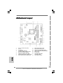 2
2
-
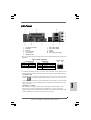 3
3
-
 4
4
-
 5
5
-
 6
6
-
 7
7
-
 8
8
-
 9
9
-
 10
10
-
 11
11
-
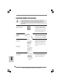 12
12
-
 13
13
-
 14
14
-
 15
15
-
 16
16
-
 17
17
-
 18
18
-
 19
19
-
 20
20
-
 21
21
-
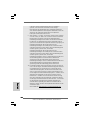 22
22
-
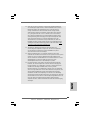 23
23
-
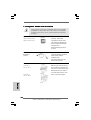 24
24
-
 25
25
-
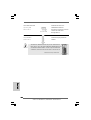 26
26
-
 27
27
-
 28
28
-
 29
29
-
 30
30
-
 31
31
-
 32
32
-
 33
33
-
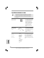 34
34
-
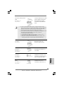 35
35
-
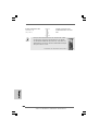 36
36
-
 37
37
-
 38
38
-
 39
39
-
 40
40
-
 41
41
-
 42
42
-
 43
43
-
 44
44
-
 45
45
-
 46
46
-
 47
47
-
 48
48
-
 49
49
-
 50
50
-
 51
51
-
 52
52
-
 53
53
-
 54
54
-
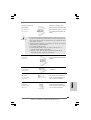 55
55
-
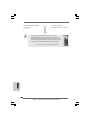 56
56
-
 57
57
-
 58
58
-
 59
59
-
 60
60
-
 61
61
-
 62
62
-
 63
63
-
 64
64
-
 65
65
-
 66
66
-
 67
67
-
 68
68
-
 69
69
-
 70
70
-
 71
71
-
 72
72
-
 73
73
-
 74
74
-
 75
75
-
 76
76
-
 77
77
-
 78
78
-
 79
79
-
 80
80
-
 81
81
-
 82
82
-
 83
83
-
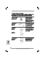 84
84
-
 85
85
-
 86
86
-
 87
87
-
 88
88
-
 89
89
-
 90
90
-
 91
91
-
 92
92
-
 93
93
-
 94
94
-
 95
95
-
 96
96
-
 97
97
-
 98
98
-
 99
99
-
 100
100
-
 101
101
-
 102
102
-
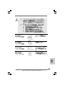 103
103
-
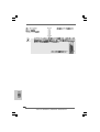 104
104
-
 105
105
-
 106
106
-
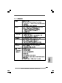 107
107
-
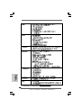 108
108
-
 109
109
-
 110
110
-
 111
111
-
 112
112
-
 113
113


ASROCK AD525PV3 Manual de usuario
- Categoría
- Placas base
- Tipo
- Manual de usuario
- Este manual también es adecuado para
en otros idiomas
- français: ASROCK AD525PV3 Manuel utilisateur
- italiano: ASROCK AD525PV3 Manuale utente
- English: ASROCK AD525PV3 User manual
- Deutsch: ASROCK AD525PV3 Benutzerhandbuch
- português: ASROCK AD525PV3 Manual do usuário
Artículos relacionados
-
ASROCK A230GC-815 El manual del propietario
-
ASROCK PV530A-ITX El manual del propietario
-
-
ASROCK A330ION-2016 El manual del propietario
-
-
ASROCK 760GM-S3 El manual del propietario
-
-
-
-
ASROCK P67 PRO Guía de inicio rápido