Peavey PV 6 Manual de usuario
- Categoría
- Mezcladores de audio
- Tipo
- Manual de usuario
Este manual también es adecuado para

PV
®
6
Compact Mixer Operations Guide
For more information on other great Peavey products, go to your local Peavey dealer or online at www.peavey.com

2
Intended to alert the user to the presence of uninsulated “dangerous voltage” within the product’s
enclosure that may be of sufficient magnitude to constitute a risk of electric shock to persons.
Intended to alert the user of the presence of important operating and maintenance (servicing)
instructions in the literature accompanying the product.
CCAAUUTTIIOONN::
Risk of electrical shock — DO NOT OPEN!
CCAAUUTTIIOONN::
To reduce the risk of electric shock, do not remove cover. No user serviceable parts inside.
Refer servicing to qualified service personnel.
WWAARRNNIINNGG::
To prevent electrical shock or fire hazard, do not expose this appliance to rain or moisture.
Before using this appliance, read the operating guide for further warnings.
Este símbolo tiene el propósito, de alertar al usuario de la presencia de “(voltaje) peligroso” sin
aislamiento dentro de la caja del producto y que puede tener una magnitud suficiente como para
constituir riesgo de descarga eléctrica.
Este símbolo tiene el propósito de alertar al usario de la presencia de instruccones importantes sobre la
operación y mantenimiento en la información que viene con el producto.
PPRREECCAAUUCCIIOONN::
Riesgo de descarga eléctrica ¡NO ABRIR!
PPRREECCAAUUCCIIOONN::
Para disminuír el riesgo de descarga eléctrica, no abra la cubierta. No hay piezas útiles
dentro. Deje todo mantenimiento en manos del personal técnico cualificado.
AADDVVEERRTTEENNCCIIAA::
Para evitar descargas eléctricas o peligro de incendio, no deje expuesto a la lluvia o
humedad este aparato Antes de usar este aparato, Iea más advertencias en la guía de operación.
Ce symbole est utilisé dans ce manuel pour indiquer à l’utilisateur la présence d’une tension dangereuse
pouvant être d’amplitude suffisante pour constituer un risque de choc électrique.
Ce symbole est utilisé dans ce manuel pour indiquer à l’utilisateur qu’il ou qu’elle trouvera d’importantes
instructions concernant l’utilisation et l’entretien de l’appareil dans le paragraphe signalé.
AATTTTEENNTTIIOONN::
Risques de choc électrique — NE PAS OUVRIR!
AATTTTEENNTTIIOONN::
Afin de réduire le risque de choc électrique, ne pas enlever le couvercle. Il ne se trouve à
l’intérieur aucune pièce pouvant être reparée par l’utilisateur. Confiez I’entretien et la réparation de
l’appareil à un réparateur Peavey agréé.
AAVVEERRTTIISSSSEEMMEENNTT
: Afin de prévenir les risques de décharge électrique ou de feu, n’exposez pas cet
appareil à la pluie ou à l’humidité. Avant d’utiliser cet appareil, lisez attentivement les avertissements
supplémentaires de ce manuel.
Dieses Symbol soll den Anwender vor unisolierten gefährlichen Spannungen innerhalb des Gehäuses
warnen, die von Ausreichender Stärke sind, um einen elektrischen Schlag verursachen zu können.
Dieses Symbol soll den Benutzer auf wichtige Instruktionen in der Bedienungsanleitung aufmerksam
machen, die Handhabung und Wartung des Produkts betreffen.
VVOORRSSIICCHHTT::
Risiko — Elektrischer Schlag! Nicht öffnen!
VVOORRSSIICCHHTT::
Um das Risiko eines elektrischen Schlages zu vermeiden, nicht die Abdeckung enfernen. Es
befinden sich keine Teile darin, die vom Anwender repariert werden könnten. Reparaturen nur von
qualifiziertem Fachpersonal durchführen lassen.
AACCHHTTUUNNGG::
Um einen elektrischen Schlag oder Feuergefahr zu vermeiden, sollte dieses Gerät nicht dem
Regen oder Feuchtigkeit ausgesetzt werden. Vor Inbetriebnahme unbedingt die Bedienungsanleitung lesen.

3
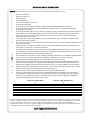
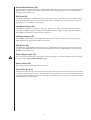
IIMMPPOORRTTAANNTT SSAAFFEETTYY IINNSSTTRRUUCCTTIIOONNSS
WWAARRNNIINNGG::
When using electrical products, basic cautions should always be followed, including the following:
1. Read these instructions.
2. Keep these instructions.
3. Heed all warnings.
4. Follow all instructions.
5. Do not use this apparatus near water.
6. Clean only with a dry cloth.
7. Do not block any of the ventilation openings. Install in accordance with manufacturer’s instructions.
8. Do not install near any heat sources such as radiators, heat registers, stoves or other apparatus (including
amplifiers) that produce heat.
9. Do not defeat the safety purpose of the polarized or grounding-type plug. A polarized plug has two blades with one
wider than the other. A grounding type plug has two blades and a third grounding plug. The wide blade or third
prong is provided for your safety. If the provided plug does not fit into your outlet, consult an electrician for
replacement of the obsolete outlet.
10. Protect the power cord from being walked on or pinched, particularly at plugs, convenience receptacles, and the
point they exit from the apparatus.
11. Note for UK only: If the colors of the wires in the mains lead of this unit do not correspond with the terminals in your
plug‚ proceed as follows:
a) The wire that is colored green and yellow must be connected to the terminal that is marked by the letter E‚ the
earth symbol‚ colored green or colored green and yellow.
b) The wire that is colored blue must be connected to the terminal that is marked with the letter N or the color black.
c) The wire that is colored brown must be connected to the terminal that is marked with the letter L or the color red.
12. Only use attachments/accessories provided by the manufacturer.
13. Use only with a cart, stand, tripod, bracket, or table specified by the manufacturer, or sold with the apparatus. When
a cart is used, use caution when moving the cart/apparatus combination to avoid injury from tip-over.
14. Unplug this apparatus during lightning storms or when unused for long periods of time.
15. Refer all servicing to qualified service personnel. Servicing is required when the apparatus has been damaged in
any way, such as power-supply cord or plug is damaged, liquid has been spilled or objects have fallen into the
apparatus, the apparatus has been exposed to rain or moisture, does not operate normally, or has been dropped.
16. Never break off the ground pin. Write for our free booklet “Shock Hazard and Grounding.” Connect only to a power
supply of the type marked on the unit adjacent to the power supply cord.
17. If this product is to be mounted in an equipment rack, rear support should be provided.
18. Exposure to extremely high noise levels may cause a permanent hearing loss. Individuals vary considerably in
susceptibility to noise-induced hearing loss, but nearly everyone will lose some hearing if exposed to sufficiently
intense noise for a sufficient time. The U.S. Government’s Occupational and Health Administration (OSHA) has
specified the following permissible noise level exposures:
Duration Per Day In Hours Sound Level dBA, Slow Response
890
692
495
397
2 100
1
1
⁄
2
102
1 105
1
⁄
2
110
1
⁄
4
or less 115
According to OSHA, any exposure in excess of the above permissible limits could result in some hearing loss. Ear plugs or protectors to the
ear canals or over the ears must be worn when operating this amplification system in order to prevent a permanent hearing loss, if exposure
is in excess of the limits as set forth above. To ensure against potentially dangerous exposure to high sound pressure levels, it is
recommended that all persons exposed to equipment capable of producing high sound pressure levels such as this amplification system be
protected by hearing protectors while this unit is in operation.
SSAAVVEE TTHHEESSEE IINNSSTTRRUUCCTTIIOONNSS!!

4
PV
®
6Compact Mixer
Description
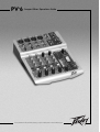
Congratulations on purchasing the Peavey PV6 compact mixer. The PV6 is a studio-quality mixing console designed to meet diverse
needs while only occupying a small space. This is the perfect console for small venue performances or home recording environments.
Please read this guide carefully to ensure your personal safety as well as the safety of your equipment.
Features
➡ XLR Mic inputs on all four channels
➡ Two Stereo channels with
1
⁄4" inputs
➡ Three-band EQ on mono channels
➡ Two-band EQ on stereo channels
➡ Clip LEDs that thoroughly monitor clipping
➡ 48V phantom power switch
➡ Effects send on every channel with stereo return
➡ Zero latency record monitoring capabilities
➡ Control room out with level control
➡ Contour control switch
➡ 80 Hz low cut switch
EENNGGLLIISSHH

5
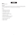
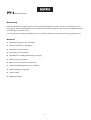
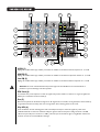
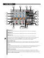
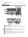
Hi EQ (1)
An active tone control (shelving type: ±15 dB) that varies the level of the high frequency range.
Mid EQ (2)
An active tone control (shelving type: ±15 dB) that varies the mid frequency range.
Low EQ (3)
An active tone control (shelving type: ±15 dB) that varies the level of the low frequency range.
Caution: Excessive low frequency boost causes greater power consumption and increases the possibility of speaker damage.
EFX Send (4)
This adjusts the level of the channel signal added to the effects mix. The effects send signal is taken after the channel
level controls (7) so that adjustments made to the level control will also affect the send level.
Pan (5)
This knob controls the placement of the signal in the stereo field. When rotated completely counterclockwise‚ the
signal is present only on the left channel; when rotated completely clockwise‚ only in the right channel.
Clip LED (6)
This light normally indicates that the channel signal level is nearing the overload point. The clip indicator circuit
monitors the signal at many points in the channel to ensure that it catches all instances of clipping. It illuminates at
+19 dBu and warns that the gain or EQ boost should be reduced. When it light,s roughly 3 dB of headroom
remains.
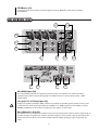
FF RR OO NN TT PP AA NN EE LL
1 8 9 10
2
3
4
5
6
7
11
12
13
14
15
16
17 18 19

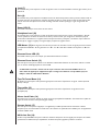
6
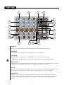
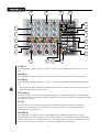
Level (7)
This is the channel output level control. The optimum setting is the 0 (unity gain) position.
Gain (8)
This control establishes the nominal operating level for the channel. The input gain can be adjusted over a wide
range to compensate for soft voices or very loud drums. To maximize the signal-to-noise ratio, the gain should be
set to the proper level with the channel level control (7) set to 0. If the clip LED comes on and remains lit, try
reducing the gain.
Power LED (9)
This LED indicates that AC power is supplied to the unit‚ the power switch is on and the unit is functioning
properly.
Headphone Level (10)
This knob sets the headphone and control room output level. To avoid damage to your hearing‚ make sure to turn
the dial fully counterclockwise before using headphones. Slowly turn the knob clockwise until a comfortable
listening level is set. Normally, the signal in the headphones is the Left/Right signal. If the Tape to Control Room
(14) is engaged‚ the tape signal is also included.
LED Meters (11)
Two four-segment LED arrays are provided to monitor the levels of the main Left/Right outputs. These meters range
from -21 dB to +19 dB. A reading of 0 db on the meter corresponds to +4 dBu at the outputs.
Phantom Power LED (12)
This LED lights when the Phantom Power Switch (13) has been engaged.
Phantom Power Switch (13)
Applies +48 VDC Voltage to the input XLR connectors to power microphones requiring phantom power.
If phantom power is used, do not connect unbalanced dynamic microphones or other devices to the XLR inputs that
cannot handle this Voltage. The Phantom Power LED (12) indicates when phantom power is on.
Tape To Control Room (14)
Depressing this switch adds the tape return to the Control Room and Headphone Outputs (24) for zero latency monitoring.
Tape to Mix (15)
Depressing this switch routes the signal from the Tape Inputs to the Main Outputs (27).
Master Level Fader (16)
The Master Fader controls the level sent to the main Left/Right outputs. Best results are obtained when this control
is set near the 0 point.
Contour Switch (17)
Engaging this switch enhances the signal by adding both bass and treble frequencies. This is especially effective at
lower volumes or for tape/CD playback.
80 Hz Low Cut (18)
The Low Cut filter has a corner frequency of 80 Hz. When engaged‚ it can improve clarity by removing low
frequencies that can make a mix sound muddy. This feature is especially useful when playing outside on a windy day
or on a hollow‚ noisy stage. These kinds of ambient noises can rob your sound system of power. Engaging this
switch removes those frequencies from the system and restores power to where it’s needed.
EFX/Return (19)
The EFX/Return Level Control adjusts the level sent to the Left/Right main bus from the return inputs.

7
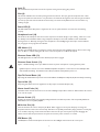
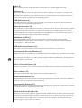
RR EE AA RR PP AA NN EE LL
20
21
22
23 24 25 26
28 27
29 30 31 32
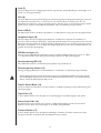
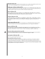
Mic (XLR) Inputs (20)
XLR balanced inputs optimized for a microphone or other low impedance source. Pin 2 is the positive input.
Because of the wide range of gain adjustment, signal levels up to +14 dBu can be accommodated.
Line (
1
⁄
4"
) Inputs (21)
1
⁄
4” balanced (TRS) 10 k Ohm impedance input. The tip is the positive input and should be used for unbalanced
inputs. It has 20 dB less gain than the XLR input and does not have phantom power available. The Mic and Line
inputs should not be used simultaneously.
Gain (Channels 1 & 2) (22)
This control establishes the nominal operating level for the channel. The input gain can be adjusted over a wide
range to compensate for soft voices or very loud drums. To maximize the signal-to-noise ratio, the gain should
be set to the proper level with the channel level control (7) set to 0. If the Clip LED comes on and remains lit,
try reducing the gain.
Stereo Inputs (23)
Channels 3 and 4 feature stereo inputs via
1
⁄4” inputs and mono XLR inputs. When the
1
⁄4" line inputs are in use‚
the XLR mic input is muted to prevent unwanted noise.

8
Control Room Outputs (24)
The Control Room Outputs feature two
1
⁄4" TRS Z-balanced jacks. These outputs can be used with Tip‚ Ring Sleeve
(TRS) balanced or Tip Sleeve (TS) unbalanced connectors. The Control Room Output Level is adjusted with the
Headphone Level Control (10).
EFX Send (25)
The EFX Send features a
1
⁄4" TRS Z-balanced jack in the master section. These outputs can be used with Tip‚ Ring
Sleeve (TRS) balanced or Tip Sleeve (TS) unbalanced connectors. The EFX mix is determined by the amount of
signal being sent to the EFX bus in each channel.
Headphone Output (26)
The Headphone Output is a
1
⁄4" TRS (tip = left; ring = right; sleeve = ground). The signal sent to this output is
normally the Left/Right mix. When the Tape to Control Room switch is engaged‚ the tape input signal is added to
the Left/Right mix and can be monitored in the headphones.
Left/Right Outputs (27)
The Left/Right Outputs feature two
1
⁄4" TRS Z-balanced jacks. These outputs can be used with Tip‚ Ring, Sleeve
(TRS) balanced or Tip, Sleeve (TS) unbalanced connectors.
EFX Return (28)
The EFX Return inputs (Left/Mono‚ Right) feature two
1
⁄4" TRS Z-balanced jacks. These outputs can be used with
Tip‚ Ring, Sleeve (TRS) balanced or Tip, Sleeve (TS) unbalanced connectors. The EFX Return is controlled via the
EFX/Return Level Control (19).
Power Adapter Input (29)
Use to connect the included power supply. Be sure the power supply is connected to the PV
®
6 before connecting
to a power source. Use 16 VAC 1 A adapter only.
Power Switch (30)
Depressing the power switch applies power to the unit.
Tape In/Out (32 & 31)
The tape input jacks are designed to accommodate tape‚ CD or computer sound card output levels. The out level is
+4 dBu for connection to a recorder or sound card input. The tape inputs can be used as an additional stereo input
by engaging the Tape to Main Mix switch (15). The tape input can also be used to monitor the recorder/sound card
output without the risk of feedback.

9
CONTOUR
LO HI
CONTOUR
LO HI
PAN
+48V
4
+
-
4
EQ
LO MID HI
+
-
+
-
+
-
HI PASS
HI PASS
EQ
LO
HI
EQ
LO
HI
+48V
BALANCE
TAPE -L/R SELECT
POWER
PHANTOM
GLOBAL
POWER
PHANTOM
RIGHT
LEFT
EFX
CLIP
GAIN
XLR
EFX
LINE
RIGHT
LEFT
XLR
LEVELGAIN
EFX
CLIP
MONO INPUT
STEREO INPUT
EFX RETURN
LEFT/MONO
RIGHT
TAPE OUTPUT
HEADPHONES
CONTROL ROOM
TAPE TO MIX
LED METER
LEFT/MONO
RIGHT
LEFT
RIGHT
MAIN OUTPUTS
EFX SEND
TAPE INPUT
GLOBAL
CONTROL ROOM
TAPE TO
2
3
1
2
3
1
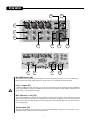
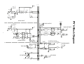
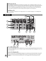
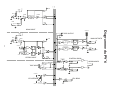
PV
®
6 Block Diagram

10
PPVV
®
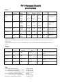
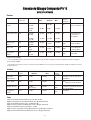
66 CCoommppaacctt CCoonnssoollee
SSPPEECCIIFFIICCAATTIIOONNSS
Function
Microphone (150
ohms)
Line (10k ohms)
Stereo Line Input
Aux Returns
Tape
Input Z
(ohms min)
2.2k
10k
10k
10k
10k
Input Gain
Setting
Max Gain
(60 dB)
Min Gain
(9 dB)
Max Gain
(40 dB)
Min Gain
(-10 dB)
Max Gain
(30 dB)
N/A
(0 dB)
N/A
(10 dB)
Nominal*
-56 dBu
-5 dBu
-36 dBu
+14 dBu
+4 dBu
+4 dBu
-10 dBV
Max
-38 dBu
+13 dBu
-18 dBu
+32 dBu
+22 dBu
+22 dBu
+12 dBu
Bal/Unbal
Bal
Bal
Unbal
Unbal
Unbal
Connector
XLR Pin 1 Gnd Pin
2 (+)‚ Pin 3 (-1)
1
⁄4" TRS; Tip (+)‚
Ring (-)‚ Sleeve
Ground
1
⁄4" TRS; Tip (+)‚
Sleeve Ground
1
⁄4" TRS; Tip (+)‚
Sleeve Ground
RCA Phone
Input Levels
Min**
-83 dBu
-31 dBu
-63 dBu
-12 dBu
-26 dBu
-17 dBu
-17 dBu
Function
Main Left/Right
Effects Sends
Headphone
Tape
Min Load Z
(ohms)
600
600
8
2.2 k
Nominal
+4 dBu
+4 dBu
+4 dBu (no load)
+4 dBu
Max
+22 dBu
+22 dBu
+22 dBu
+22 dBu
Bal/Unbal
Bal
Bal
Unbal
Unbal
Connector
1
⁄4" TRS: Tip (+); Ring (-); Sleeve
Ground
1
⁄4" TRS; Tip (+)‚ Sleeve Ground
1
⁄4" TRS; Tip Left‚ Ring Right‚ Sleeve
Ground
RCA Phone
Output Level
0 dBu = 0.775 V (RMS)
** Min Input Level (sensitivity) is the smallest signal that will produce nominal output (+4 dBu) with channel and master faders set for
maximum gain.
* Nominal settings are defined as all controls set at 0 dB (or 50% rotation for rotary pots) except the gain adjustment pot which is as
specified.
0 dBu = 0.775 V (RMS)
Gain
Mic Input Gain Adjustment Range: 10 dB to 60 dB
Mic Input to Left/Right Balance Output 87 dB (max gain)
Line Input Gain Adjustment Range: -10 dB to 40 dB
Line Input to Left/Right Balance Output 67 dB (max gain)
Stereo Line Input Gain Adjustment Range: 10 dB
Stereo Line Input to Left/Right Output 28 dB (max gain)
Aux Return to Left/Right Balance Output 21 dB (max gain)
Inputs
Outputs

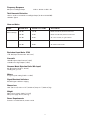
11
Output
Master Left/Right
Effects Sends
Residual Noise
-98 dBu
-90 dBu
-84 dBu
-96 dBu
-84 dBu
S/N Ratio (ref. +4 dBu)
102 dB
94 dB
90 dB
100 dB
88 dB
Test Conditions
Master Fader Down‚ Channel Levels Down
Master Fader Nominal‚ Channel Levels Down
All controls nominal‚ mic gain minimum
All controls off
All channel sends nominal
(Hum and noise measurements: 22 Hz to 22 kHz BW)
Frequency Response
Mic Input to Left/Right Output 14 Hz to 25 kHz +0 dB/-1 dB
Total Harmonic Distortion
<0.01% 20 Hz to 20 kHz Mic to Left/Right Output (10 Hz to 80 kHz BW)
<0.005% Typical
Equivalent Input Noise (EIN)
-129 dBu (input terminated with 150 ohms)
Crosstalk
>80 dB Adjacent Input Channels (1 kHz)
>75 dB Left to Right Outputs (1 kHz)
Common Mode Rejection Ratio (Mic Input)
50 dB minimum (20 Hz to 20 kHz)
70 dB typical @ 1 kHz
Meters
4-segment‚ peak reading (0 dB = +4 dBu)
Signal/Overload Indicators
Red LED lights 3 dB below clipping
Dimensions
7.55" (19.18 cm) wide x 9.717" (24.68 cm) deep x 2.7" (6.86 cm) high
Weight
Without power supply: 3.9 lbs (1.77 kg)
With power supply: 5.1 lbs (2.31 kg)
Power Requirements
Domestic: 16.5 VAC 60 Hz; 8 watts nominal
Hum and Noise

12
DDEEUUTTSSCCHH
PV
®
6 Kompakt-Mischpult
Beschreibung
Herzlichen Glückwunsch! Sie haben gerade ein Peavey PV6 Kompakt-Mischpult erworben. Der PV6 ist ein Mischpult, das trotz
seiner geringen Maße Studioqualität liefert und die verschiedensten Bedürfnisse erfüllt. Der PV6 ist das perfekte Mischpult für kleine
Veranstaltungen oder das Heimstudio.
Lesen Sie sich diese Anleitung bitte sorgfältig durch, damit sowohl Ihre Sicherheit als auch die Ihrer Ausrüstung gewährleistet ist.
Merkmale
➡ XLR-Mikrofoneingänge an allen vier Kanälen
➡ Zwei Stereo-Kanäle mit 1/4"-Eingängen
➡ 3-Band-EQ an den Monokanälen
➡ 2-Band-EQ an den Stereokanälen
➡ Clip-LEDs für die sorgfältige Überwachung von Clipping
➡ 48-V-Phantomspeisung-Schalter
➡ Effects Send an jedem Kanal mit Stereo Return
➡ Aufnahmeüberwachungsfunktionen ohne Latenzzeit
➡ Abhörraumausgang mit Pegelregle
➡ Contour-Schalter
➡ 80-Hz-Tiefpassschalter

13
Hi EQ (1)
Aktiver Klangregler (stufenlos regelbar: ±15 dB), mit dem der Pegel im Hochfrequenzbereich variiert werden
kann.
Mid EQ (2)
Aktiver Klangregler (stufenlos regelbar, ±15 dB), mit dem der Mittenfrequenzbereich variiert werden kann.
Low EQ (3)
Aktiver Klangregler (stufenlos regelbar: ±15 dB), mit dem der Pegel im Niederfrequenzbereich variiert werden
kann.
Achtung: Ein übermäßiges Anheben der Niederfrequenzen führt zu erhöhtem Stromverbrauch und steigert das
Risiko einer Beschädigung der Lautsprecher.
EFX Send (4)
Mit diesem Regler wird der Pegel des Kanalsignals festgelegt, das dem Effects-Mix zugemischt wird. Das Effects-
Send-Signal wird hinter den Kanalpegelreglern (7) abgenommen, sodass sich Einstellungen des Pegelreglers auch auf
den Send-Pegel auswirken.
Pan (5)
Mit diesem Regler wird die Platzierung des Signals im Stereofeld festgelegt. Bei vollständiger Drehung im
entgegengesetzten Uhrzeigersinn ist das Signal nur im linken Kanal präsent, bei vollständiger Drehung im
Uhrzeigersinn nur im rechten Kanal.
Clip-LED (6)
Diese LED zeigt in der Regel an, dass sich der Kanalsignalpegel dem Überlastungspunkt nähert. Die Clip-
Anzeigeschaltung überwacht das Signal an vielen Punkten im Kanal um zu gewährleisten, dass sämtliche Clipping-
Situationen erfasst werden. Die LED leuchtet bei +19 dBu auf und warnt, wenn Gain oder EQ Boost verringert
werden müssen. Leuchtet sie auf, stehen nur noch knapp 3 dB Headroom zur Verfügung.
1 8 9 10
2
3
4
5
6
7
11
12
13
14
15
16
17 18 19
VV OO RR DD EE RR SS EE II TT EE

14
Level (7)
Mit diesem Regler wird der Ausgangspegel des Kanals eingestellt. Die optimale Einstellung für diesen Regler ist die
Position „0“ (Leistungsverstärkung).
Gain (8)
Mit diesem Regler wird der Nennbetriebspegel für den Kanal eingestellt. Die Eingangsverstärkung kann über einen
weiten Bereich eingestellt werden, um zarte Stimmen oder sehr laute Drums zu kompensieren. Um den
Rauschabstand zu maximieren, sollte die Verstärkung auf den korrekten Pegel mit dem Kanal-Pegelregler (7) auf 0
gestellt werden. Leuchtet die Clip-LED kontinuierlich auf, sollte die Verstärkung verringert werden.
Power-LED (9)
Die LED leuchtet auf, wenn das Gerät eingeschaltet ist, mit Wechselstrom versorgt wird und störungsfrei arbeitet.
Headphone-Pegel (10)
Mit diesem Regler wird der Ausgangspegel für Kopfhörer und Abhörraum eingestellt. Um Hörschäden zu
vermeiden, muss dieser Regler vollständig im entgegengesetzten Uhrzeigersinn heruntergedreht werden, bevor Sie
Kopfhörer verwenden. Drehen Sie den Knopf langsam im Uhrzeigersinn, bis ein angenehmer Hörpegel erreicht ist.
Das Signal in den Kopfhörern ist in der Regel das Left/Right-Signal. Wird der Tape-to-Control-Room-Schalter (14)
gedrückt‚ wird das Tape-Signal zugefügt.
LED-Messanzeigen (11)
Zwei Vier-Segment-LED-Anzeigen überwachen die Pegel der Main Left/Right-Ausgänge. Sie sind von -21 dB bis
+19 dB geeicht. Ein Wert von 0 dB auf der Messanzeige entspricht +4 dBu an den Ausgängen.
Phantomspeisung-LED (12)
Diese LED leuchtet auf, wenn der Phantomspeisung-Schalter (13) gedrückt wurde.
Phantomspeisung-Schalter (13)
Versorgt die Eingangs-XLR-Stecker mit 48 V Gleichstrom, um Mikrofone mit Phantomspeisung zu betreiben.
Wird die Phantomspeisung verwendet, dürfen keine unsymmetrierten dynamischen Mikrofone oder anderen Geräte
an die XLR-Eingänge angeschlossen werden, die diese Spannung nicht bearbeiten können. Ist die Phantomspeisung
aktiviert, leuchtet die Phantomspeisung-LED (12) auf.
Tape To Control Room (14)
Mit diesem Schalter wird Tape Return den Control-Room- und Kopfhörerausgängen (24) zur Überwachung ohne
Latenzzeit zugefügt.
Tape to Mix (15)
Ist dieser Schalter aktiviert, wird das Signal von den Tape-Eingängen zu den Main-Ausgängen (27) geleitet.
Master-Level-Fader (16)
Der Master-Fader regelt den Pegel, der an die Left- und Right-Hauptausgänge gesendet wird. Die besten
Ergebnisse werden erzielt, wenn dieser Regler um die Position 0 eingestellt wird.
Contour-Schalter (17)
Ist dieser Schalter aktiviert, wird das Signal durch Hinzufügen von Bässen und Höhen verstärkt. Dies ist bei
geringeren Lautstärken für Tonband- bzw. CD-Playback besonders wirksam.

15
20
21
22
23 24 25 26
28 27
29 30 31 32
Mic- (XLR-) Eingänge (20)
Symmetrierte XLR-Eingänge, die für ein Mikrofon oder eine andere niederohmige Quelle optimiert wurden. Stift 2
ist der positive Eingang. Auf Grund der Vielzahl an möglichen Gain-Einstellungen können Signalpegel von bis zu +14
dBu erreicht werden.
Line- (1/4"-) Eingänge (21)
Dies ist ein symmetrierter 1/4"-(TRS)-Klinkeneingang mit einer Impedanz von 10 kOhm. Die Spitze ist der positive
Eingang und sollte für unsymmetrierte Eingänge verwendet werden. Sein Gain liegt 20 dB unter dem des XLR-
Eingangs, und er hat keine Phantomspeisung. Die Mic- und Line-Eingänge sollten nicht gleichzeitig verwendet
werden.
80 Hz Low Cut (18)
Der Tiefpassfilter hat eine Eckfrequenz von 80 Hz. Ist er aktiviert, kann er die Klarheit verstärken, indem er die
tiefen Frequenzen herausnimmt, durch die ein Mix unsauber klingen kann. Diese Funktion ist besonders hilfreich bei
Außenveranstaltungen an einem windigen Tag oder auf einer weiten, lauten Bühne. Diese Umgebungsgeräusche
können die Leistung des Beschallungssystems beeinträchtigen. Mittels dieses Schalters werden diese Frequenzen
aus dem System herausgenommen und die Leistung wieder da eingesetzt, wo sie benötigt wird.
EFX/Return (19)
Mit dem EFX/Return-Pegelregler wird der Pegel geregelt, der von den Return-Eingängen an den Left/Right-Main-
Bus gesendet wird.
RR ÜÜ CC KK SS EE II TT EE

16
Gain (Kanäle 1 und 2) (22)
Mit diesem Regler wird der Nennbetriebspegel für den Kanal eingestellt. Die Eingangsverstärkung kann über einen
weiten Bereich eingestellt werden, um zarte Stimmen oder sehr laute Drums zu kompensieren. Um den
Rauschabstand zu maximieren, sollte die Verstärkung auf den korrekten Pegel mit dem Kanal-Pegelregler (7) auf 0
gestellt werden. Leuchtet die Clip-LED kontinuierlich auf, sollte die Verstärkung verringert werden.
Stereo-Eingänge (23)
Die Kanäle 3 und 4 sind über 1/4"- und Mono-XLR-Eingänge mit Stereoeingängen ausgestattet. Werden die 1/4"-
Line-Eingänge verwendet, ist der XLR-Mikroeingang stummgeschaltet, um unerwünschtes Rauschen zu verhindern.
Control-Room-Ausgänge (24)
Die Control-Room-Ausgänge verfügen über zwei symmetrierte 1/4"-Klinken. Diese Ausgänge können mit
symmetrierten Klinkensteckern (Spitze, Ring, Masse) oder unsymmetrierten Klinkensteckern (Spitze, Masse)
verwendet werden. Der Control-Room-Ausgangspegel wird mit dem Headphone-Pegelregler (10) eingestellt.
EFX Send (25)
Der EFX Send verfügt über eine symmetrierte 1/4"-Klinke in der Master-Stufe. Diese Ausgänge können mit
symmetrierten Klinkensteckern (Spitze, Ring, Masse) oder unsymmetrierten Klinkensteckern (Spitze, Masse)
verwendet werden. Der EFX-Mix wird durch die Stärke des Signals festgelegt, das an den EFX-Bus in jedem Kanal
gesendet wird.
Kopfhörerausgang (26)
Der Kopfhörerausgang ist eine 1/4"-Klinke (Spitze = links, Ring = rechts, Masse = Erde). Das an diesen Ausgang
gesendete Signal ist in der Regel der Left/Right-Mix. Ist der Tape-to-Control-Room-Schalter aktiviert, wird das
Tape-Eingangssignal dem Left/Right-Mix zugefügt und kann über die Kopfhörer überwacht werden.
Left/Right-Ausgänge (27)
Die Left/Right-Ausgänge verfügen über zwei symmetrierte 1/4"-Klinken. Diese Ausgänge können mit symmetrierten
Klinkensteckern (Spitze, Ring, Masse) oder unsymmetrierten Klinkensteckern (Spitze, Masse) verwendet werden.
EFX Return (28)
Die EFX-Return-Eingänge (Left/Mono, Right) verfügen über zwei symmetrierte 1/4"-Klinken. Diese Ausgänge
können mit symmetrierten Klinkensteckern (Spitze, Ring, Masse) oder unsymmetrierten Klinkensteckern (Spitze,
Masse) verwendet werden. EFX Return wird über den EFX/Return-Pegelregler (19) geregelt.
Netzadaptereingang (29)
Zum Anschließen des beiliegenden Netzteils. Das Netzteil muss an den PV
®
6 angeschlossen werden, bevor dieser
an eine Stromquelle angeschlossen wird. Nur Adapter mit 16 V Wechselstrom, 1 A verwenden.
Power-Schalter (30)
Durch Drücken dieses Schalters wird das Gerät mit Netzstrom versorgt.
Tape In/Out (32 und 31)
An die Tape-Eingangsklinken können die Ausgangspegel von Tonband, CD-Player oder Computer-Soundkarte
angeschlossen werden. Der Ausgangspegel beträgt +4 dBu für den Anschluss an einen Tonband- oder
Soundkarteneingang. Die Tape-Eingänge können als zusätzlicher Stereoeingang verwendet werden, wenn der Tape-
to-Main-Mix-Schalter (15) gedrückt wird. Der Tape-Eingang kann zudem verwendet werden, um den Tonband-
bzw. Soundkartenausgang ohne die Gefahr eines Feedbacks zu überwachen.

17
PV
®
6 Console de Mixage Compacte
Description
Félicitations pour l’achat de la Peavey PV6, unité de mixage au format table. La PV6 est idéale pour toutes applications
d’enregistrement ou de diffusion où la compacité du matériel est importante.
Caractéristiques
➡ Entrées XLR Micro sur les quatres canaux principaux
➡ Deux canaux Stéréo avec entrées Jack 1/4" (6.35mm)
➡ Egalisation trois-bandes sur les canaux Mono
➡ Egalisation deux-bandes sur les canaux Stéréo
➡ LEDs de niveau pour prévenir tout écrêtage du signal
➡ 4Alimantation Phantom 48V à interrupteu
➡ Envoi vers effet sur chaque canal avec retour d’effets Stéréo
➡ Possibilité d’enregistrement sans retard (Zero Latency)
➡ Sortie d’écoute additionnelle (Control Room) avec contrôle niveau
➡ Interrupteur de contour (filtre égaliseur en sortie)
➡ filtre coupe_bas 80 Hz à interrupteur
FFRRAANNÇÇAAIISS

18
PP AA NN NN EE AA UU DD EE DD EE VV AA NN TT
1 8 9 10
2
3
4
5
6
7
11
12
13
14
15
16
17 18 19
Hi EQ (1)
Réglage de tonalité actif de type escalier permettant de modifier les niveaux des hautes fréquences de +/-15 dB.
Mid EQ (2)
Réglage de tonalité actif de type escalier permettant de modifier les niveaux des fréquences médium de +/-15 dB.
Low EQ (3)
Réglage de tonalité actif de type escalier permettant de modifier les niveaux des basses fréquences de +/-15 dB.
Attention: Un niveau excessif de basses fréquences augmente considérablement les consommations en
puissance et peut endommager vos hauts-parleurs.
EFX Send (4)
Ce contrôle vous permet d’ajuster le niveau du signal envoyé au bus d’effet. Le niveau de ce signal est également
affecté par le contrôle de niveau du canal (7).
Pan (5)
Détermine la position du canal dans l’image stéréo. En augmentant ce contrôle, vers la gauche(sens contre-horaire),
le signal diminuera dans le champ droit tout en augmentant dans le champ gauche et vice-versa.
Clip LED (6)
(Leds d’indication de seuil d’écrètage) Ces Leds vous indiquent lorsque le niveau du signal est proche de la
sensibilité maximale. Le circuit de détection analyse le signal à toutes les étapes du routage de clui-ci et la LED
s’illuminera pour indiquer un niveau de +19dBu, prévenant que les contrôles de gain ou d’égalisation doivent être
atténués. Ce seuil est environ 3dB avant écrètage.

19
Level (7)
Ce contrôle vous permet d’ajuster le niveau du signal de sortie. Le niveau d’utilisation commun (gain unitaire) est en
position 0.
Gain (8)
Ce contrôle vous permet d’ajuster la sensibilité d’entrée du canal correspondant, celui-ci pouvant s’accommoder de
la plupart des types de signaux. Pour maximiser la qualité du signal, le niveau de celui-ci dans le canal doit être fait
avec le niveau de sortie ajusté à 0. Si la Led d’écrètage s’illumine de facon prolongée, le gain du signal doit être
réduit.
Power LED (9)
Cette LED vous indique si votre unité est sous tension.
Headphone Level (10)
Ce contrôle vous permet d’ajuster le niveau du signal d’écoute (sortie casque et sortie ‘Control Room’). Assurez-
vous de positionner le volume au minimum lors d’une première écoute, puis d’augmenter doucement jusqu’au
niveau désiré. Généralement, le signal d’écoute correspond au sorties principales; si le sélecteur ‘Tape to Control
Room’(14) est engagé, le signal pré-enregistré (Tape) est ajouté au signal d’écoute.
LED Meters (11)Deux rangées de 4 Leds vous pemettent de contrôler le niveau du signal présents aux sorties
principales Droite/Gauche. Ils sont gradués de -21 dB à +19 dB et le 0 db de l’échelle correspond à +4 dBu aux
sorties.
Phantom Power LED (12)
Cette LED s’illumine pour vous indiquer que l’alimentation Phantom est active.
Phantom Power Switch (13)
Cet interrupteur vous permet d’activer ou de désactiver l’alimentation Phantom de votre unité. Celle-ci se traduit
par une tension de 48V appliquées aux entrées XLR.
Si l’alimentation est active, assurez-vous de ne pas connecter aux connecteurs XLR des micros ou
autres unités de signal qui ne suppoteraient pas ce voltage. La Led témoin correspondante (12) vous
indique le status de l’alimentation Phantom.
Tape To Control Room (14)
En activant cet interrupteur vous ajoutez le signal présent aux entrées ‘Tape Return’ au signal d’écoute (Control
Room) et casque.
Tape to Mix (15)
En activant cet interrupteur vous ajoutez le signal présent aux entrées ‘Tape Return’ au signal des sorties
principales (27).
Master Level Fader (16)
Ces faders vous permettent d’ajuster le niveau des sorties principales Droite/Gauche. Pour maximiser la qualité du
signal, le niveau de celui-ci sera ajusté à 0 (gain unitaire).
Contour Switch (17)
Cet interrupteur vous permet d’appliquer une égalisation pré-définie ajoutant à la fois des hautes et basses
fréquences pour une accentuation du relief sonore. Ce sélecteur est particulièrement efficace pour des applications
musicales à faible niveau.
80 Hz Low Cut (18)
Ce filtre coupe-bas 80Hz vous permet d’éliminer les basses fréquences de votre signal pour lui ajouter de la clarté,
particulièrement efficace lorsque l’amplification des basses fréquences gaspille la puissance nécessaire.

20
PP AA NN NN EE AA UU PP OO SS TT ÉÉ RR II EE UU RR
20
21
22
23 24 25 26
28 27
29 30 31 32
Mic (XLR) Inputs (20)
Ces entrées XLR symétrisées sont optimisées pour la connexion d’un microphone où toute source basse-
impédance (Pin 2 positive). De part la large plage de sensibilité d’entrée, on pourra obtenir jusqu’à +14dB
d’augmentation.
Line (Jack 1/4"- 6.35mm) Inputs (21)
Ce Jack 1/4” (6.35mm) symétrique (TRS) possède une impédance de 10 k Ohm (pointe positive) et vous permet
de connecter une source sonore asymétrique Sa sensibilité est de –20dB comparée à l’entrée XLR. Les entrées
XLR(Mic) et Jack(Line) du même canal ne devraient pas être utilisées en même temps.
Gain (Channels 1 & 2) (22)
Ce contrôle vous permet d’ajuster la sensibilité d’entrée du canal correspondant, celui-ci pouvant s’accommoder de
la plupart des types de signaux. Pour maximiser la qualité du signal, le niveau de celui-ci dans le canal doit être fait
avec le niveau de sortie ajusté à 0. Si la Led d’écrètage s’illumine de facon prolongée, le gain du signal doit être
réduit.
EFX/Return (19)
Ce contrôle vous permet d’ajuster le niveau du signal des entrées ‘EFX Return’ dans les bus principaux
Droite/Gauche.

21
Stereo Inputs (23)
Les canaux 3 et 4 possèdent des entrées Stéréo par l’intermédiaire de paires de XLR ou Jack Mono. Dans ce mode
d’utilisation, les entrées micro XLR sont désactivées pour prévenir tout bruit parasite.
Control Room Outputs (24)
Les sorties d’écoute sont composées de deux Jack 1/4" symétriques (TRS). Ces sorties peuvent être utilisées avec
des Jacks 2 (TS) ou 3 (TRS) conducteurs. Le niveau du signal à ces sorties peut être ajusté grace au contrôle de
niveau de casque (10).
EFX Send (25)
La sortie du bus d’effet est un Jack 1/4" symétrique (TRS). Cette sortie vous permet d’envoyer le signal somme
déterminé par les contrôles EFX de chaque canal à un processeur externe. Cette sortie peut être utilisée avec un
Jacks 2 (TS) ou 3 (TRS) conducteurs.
Headphone Output (26)
La sortie du bus d’effet est un Jack 1/4" symétrique (TRS, pointe = gauche; anneau = droit; corps = masse).
Généralement, le signal d’écoute correspond au sorties principales; si le sélecteur ‘Tape to Control Room’(14) est
engagé, le signal pré-enregistré (Tape) est ajouté au signal d’écoute.
Left/Right Outputs (27)
Les sorties principales Droite/Gauche sont composées de deux Jack 1/4" symétriques (TRS). Ces sorties peuvent
être utilisées avec des Jacks 2 (TS) ou 3 (TRS) conducteurs.
EFX Return (28)
Les entrées de retour f’effets (EFX Return) sont composées de deux Jack 1/4" symétriques (TRS). Ces sorties
peuvent être utilisées avec des Jacks 2 (TS) ou 3 (TRS) conducteurs et leur niveau ajusté par le contrôle EFX/Return
Level (19).
Power Adapter Input (29)
Ce connecteur vous permet de connecter votre unité à sa source d’alimentation électrique. Assurez-vous de la
connexion à votre unité avant celle à la source d’alimentation électrique. N’utilisez que l’adaptateur fournit avec
votre unité où un remplacement aux charactéristiques identiques 16 VAC 1 A.
Power Switch (30)
Cet interrupteur vous permet de mettre votre unité sous/hors tension.
Tape In/Out (32 & 31)
Les entrées Tape vous permettent d’envoyer un signal à votre unité depuis un lecteur K7, CD, une carte son
d’ordinateur,… Elles représentent effectivement une entrée Stéréo additionnelle. En engageant l’interrupteur ‘Tape
to Main Mix’ (15), ces entrées vous permettent également de contrôler le niveau du signal de sortie de votre
enregistreur / carte son sans risque d’effet de boucle.

22
Diagramme du PV
®
6
CONTOUR
LO HI
CONTOUR
LO HI
PAN
+48V
4
+
-
4
EQ
LO MID HI
+
-
+
-
+
-
HI PASS
HI PASS
EQ
LO
HI
EQ
LO
HI
+48V
BALANCE
TAPE -L/R SELECT
POWER
PHANTOM
GLOBAL
POWER
PHANTOM
RIGHT
LEFT
EFX
CLIP
GAIN
XLR
EFX
LINE
RIGHT
LEFT
XLR
LEVELGAIN
EFX
CLIP
MONO INPUT
STEREO INPUT
EFX RETURN
LEFT/MONO
RIGHT
TAPE OUTPUT
HEADPHONES
CONTROL ROOM
TAPE TO MIX
LED METER
LEFT/MONO
RIGHT
LEFT
RIGHT
MAIN OUTPUTS
EFX SEND
TAPE INPUT
GLOBAL
CONTROL ROOM
TAPE TO
2
3
1
2
3
1

23
CCoonnssoollee ddee MMiixxaaggee CCoommppaaccttee PPVV
®
66
SSPPEECCIIFFIICCAATTIIOONNSS
Entrées
Fonction
Microphone (150
ohms)
Ligne (10k ohms)
Entrées Ligne
Stereo
Retour Aux
Enregistreur/
Platine
Impédance Z
(ohms min)
2.2k
10k
10k
10k
10k
Gain d’Entrée
Max Gain
(60 dB)
Min Gain
(9 dB)
Max Gain
(40 dB)
Min Gain
(-10 dB)
Max Gain
(30 dB)
N/A
(0 dB)
N/A
(10 dB)
Nominal*
-56 dBu
-5 dBu
-36 dBu
+14 dBu
+4 dBu
+4 dBu
-10 dBV
Max
-38 dBu
+13 dBu
-18 dBu
+32 dBu
+22 dBu
+22 dBu
+12 dBu
Bal/Unbal
(Symétrique
/Asymétrique)
Bal
Bal
Unbal
Unbal
Unbal
Connecteur
XLR Pin 1 Masse
Pin 2 (+)‚ Pin 3 (-1)
1/4" TRS; Pointe
(+)‚Anneau (-)‚
CorpsMasse
1/4" TRS; Pointe
(+)‚Corps Masse
1/4" TRS; Pointe
(+)‚Corps Masse
Prise RCA
Niveaux d’Entrée
Min**
-83 dBu
-31 dBu
-63 dBu
-12 dBu
-26 dBu
-17 dBu
-17 dBu
0 dBu = 0.775 V (RMS)
** Le niveau minimum d’entrée est donné avec les contrôles de gain de canal et principaux en position maximum et produira un signal de
niveau nominal (+4bBu).
* Les niveaux sont donnés avec tous les contrôles en position 0dB (ou à mi-course pour les potentiomètres rotatifs) à l’exception du contrôle
de gain mentionné.
Sorties
Function
Principales
Gauche/Droite
Envoi d’Effets
Casque d’Ecoute
Enregistreur/
Platine
Impédance Z
(ohms)
600
600
8
2.2 k
Nominal
+4 dBu
+4 dBu
+4 dBu
(sans charge)
+4 dBu
Max
+22 dBu
+22 dBu
+22 dBu
+22 dBu
Bal/Unbal
(Symétrique
/Asymétrique)
Bal
Bal
Unbal
Unbal
Connecteur
1/4" TRS: Pointe (+); Anneau (-);
CorpsMasse
1/4"
TRS; Pointe (+)‚Corps Masse
1/4" TRS; Pointe Gauche‚ Anneau
Droit‚ Corps Masse
Peris RCA
0 dBu = 0.775 V (RMS)
Gain
Plage de Sensibilité d’entrée Microphone: 10 dB à 60 dB
Rapport entrée Micro/Sorties Gauche/Droite: 87 dB (gain maximum)
Plage de Sensibilité d’entrée Ligne: -10 dB à 40 dB
Rapport entrée Ligne/Sorties Gauche/Droite: 67 dB (gain maximum)
Plage de Sensibilité d’entrée Ligne Stéréo: 10 dB
Rapport entrée Ligne Stéréo/Sorties Gauche/Droite: 28 dB (gain maximum)
Rapport entrée Auxiliaire/Sorties Gauche/Droite: 21 dB (gain maximum)
Niveaux de Sortie

24
Sortie
Sorties
Gauche/Droite
Sortie pour envoi
d’effets
Bruit Résiduel
-98 dBu
-90 dBu
-84 dBu
-96 dBu
-84 dBu
Rapport Signal/Bruit
(réf. +4 dBu)
102 dB
94 dB
90 dB
100 dB
88 dB
Conditions de Mesure
Fader principaux et gain de canaux en position minimum
Fader principaux en position unitaire et gain de canaux en
position minimum
Tous les contrôles en position unitaire, gain de microphone
au minimum
Tous les contrôles au minimum
Tous les contrôles en position unitaire
(Ecoute (mesure) du bruit de 22 Hz à 22 kHz BW)
Réponse en Fréquences
Comparaison entrée Micro/ Sorties Gauche/Droite: de 14 Hz à 25 kHz +0 dB/-1 dB
Distortion d’Harmoniques
<0.01% 20 Hz à 20 kHz Comparaison entrée Micro/ Sorties Gauche/Droite (10 Hz à 80 kHz BW)
<0.005% Généralement mesuré
Bruit Equivalent en Entrée (EIN
-129 dBu (150 ohms de charge)
Bruit entre canaux
>80 dB entre canaux d’entrée (1 kHz)
>75 dB entre canaux de sorties principales (1 kHz)
Rapport de Rejet (entrée Micro)
50 dB minimum (20 Hz à 20 kHz)
70 dB @ 1 kHz généralement mesuré
Rangée de LED
4-unité‚ 0 dB = +4 dBu
Indicateurs d’Ecrètage
LED rouge s’illumine 3 dB avant seuil d’écrètage
Dimensions
7.55" (19.18 cm) de large x 9.717" (24.68 cm) de profondeur x 2.7" (6.86 cm) de hauteur
Poids
Avec transformateur d’alimentation: 3.9 lbs (1.77 kg)
Sans transformateur d’alimentation: 5.1 lbs (2.31 kg)
Consommation Electrique
16.5 VAC 60 Hz; 8 watts
Mesure de Bruits

25
PV
®
6 Mezcladora Compacta
Descripción
Felicidades en la compre de tu mezcladora compacta PV6 de Peavey. La PV6 es una consola con calidad para mezclas de estudio
diseñada para cubrir necesidades diversas mientras ocupa un espacio pequeño. Es la consola perfecta para presentaciones en lugares
chicos o para grabación en casa.
Por favor lee esta guía cuidadosamente para asegurar tu seguridad personal así como la seguridad de tu equipo.
Características:
➡ Entradas de micrófono XLR en los cuatro canales
➡ Dos canales estéreo con entradas de 1/4”
➡ Ecualizador de tres bandas en los canales mono
➡ Ecualizador de dos bandas en canales estéreo
➡ LEDs de clip que monitorean cuidadosamente la saturación
➡ Interruptor de corriente phantom de 48V
➡ Envío para efectos en todos los canales con retorno estéreo
➡ Capacidad de monitoreo durante grabación sin retraso
➡ Salida de cuarto de control con control de nivel
➡ Interruptor de control de contorno
➡ Interruptor de recorte de graves a 80 Hz
EESSPPAAÑÑOOLL

26
PP AA NN EE LL FF RR OO NN TT AA LL
1 8 9 10
2
3
4
5
6
7
11
12
13
14
15
16
17 18 19
EQ Agudo (1)
Un control de tono activo (tipo shelving ±15 dB) que varía el nivel en el rango de frecuencias agudas.
EQ Medio (2)
Un control de tono activo (tipo shelving ±15 dB) que varía el nivel en el rango de frecuencias medias.
EQ Grave (3)
Un control de tono activo (tipo shelving ±15 dB) que varía el nivel en el rango de frecuencias graves.
Precaución: El incremento excesivo de frecuencias graves genera mayor consumo energético e incrementa las
posibilidades de daños en los parlantes.Attention: Un niveau excessif de basses fréquences augmente
considérablement les consommations en puissance et peut endommager vos hauts-parleurs.
Envío de Efectos (4)
Este control ajusta el nivel de la señal del canal que se envía a la mezcla de efectos. La señal de envío de efectos
sale después del control de nivel (7), por lo que los ajustes que se hagan al nivel afectarán también el nivel del
envío.
Pan (5)
Esta perilla controla la posición de la señal en el campo estéreo. Cuando es rotada completamente en contra de las
manecillas del reloj la señal estará presente sólo en el canal izquierdo, cuando es rotada completamente en
dirección de las manecillas del reloj la señal estará presente sólo en el canal derecho.
LED de saturación (6)
Esta luz normalmente indica que el nivel del canal está cerca de la saturación. Los circuitos de este indicador
monitorean la señal en varios puntos en el canal para asegurar la identificación de cualquier punto de saturación. Se
ilumina a + 19 dBu e indica que la ganancia o los incrementos del ecualizador deben ser reducidos. Al encenderse
quedan aproximadamente 3 dB de umbral.

27
Nivel (7)
Este es el control de nivel de salida del canal. La posición óptima es la posición 0 (ganancia unitaria).
Ganancia (8)
Este control establece el nivel nominal de operación del canal. La ganancia de entrada puede ser ajustada en un
rango amplio para compensar voces muy suaves o baterías muy fuertes. Para maximizar la razón señal-ruido, la
ganancia debe ser ajustada al nivel apropiado con el control de nivel (7) ajustado a 0. Si el LED de saturación se
enciende y permanece encendido, trata de reducir el la ganancia.
LED de Corriente (9)
Este LED indica que la unidad cuenta con corriente CA, que el interruptor de corriente está en la posición de
encendido y que la unidad funciona apropiadamente.
Nivel de Auriculares (10)
Esta perilla ajusta el nivel de salida para los auriculares y el cuarto de control. Para evitar dañar los oídos, asegúrate
que la perilla esté rotada completamente en contra de la dirección de las manecillas el reloj antes de usar los
auriculares. Lentamente rota la perilla en dirección de las manecillas del reloj hasta encontrar un nivel cómodo para
escuchar. Normalmente, la señal en los auriculares es la señal L/R (Izq./der.). Si está activado el selector Cinta a
Cuarto de Control (14), la señal de la cinta también se escuchará.
Medidores de LED (11)
Dos medidores LED de cuatro segmentos se incluyen para monitorear los niveles de salida principal
Izquierda/Derecha. Estos medidores tienen un rango de – 21 dB a + 19 dB. Cuando el medidor marca 0 dB
corresponderá a + 4 dBu en las salidas.
LED de Corriente Phantom (12)
Este LED se enciende para indicar que el Interruptor de Corriente Phantom (13) está activado.
Interruptor de Corriente Phantom (13)
Aplica una corriente de +48 VDC a las entradas XLR para alimentar micrófonos que requieran corriente phantom.
Si se usa la corriente phantom, no se deben conectar micrófonos dinámicos no balanceados u otros aparatos a las
entradas XLR que no puedan trabajar con este voltaje. El LED de Corriente Phantom (12) indica cuando la
corriente phantom está encendida.
Cinta a Cuarto de Control (14)
Oprimir este interruptor añade el retorno de la cinta a las salidas del cuarto de control y de auriculares (24) para
monitoreo sin retraso.
Cinta a Mezcla (15)
Este control manda la señal de las entradas de cinta a las salidas principales (27).
Fader de Nivel Maestro (16)
El Fader Maestro controla el nivel enviado a las salidas principales Izquierda y Derecha. Los mejores resultados se
obtienen cuando este control está cerca de la posición 0.
Interruptor de Contorno (17)
Activar este interruptor enriquece la señal añadiendo frecuencias graves y agudas. Esto es particularmente efectivo
en volúmenes bajos o en reproducción de cintas o CDs.
Recorte de Graves de 80 Hz (18)
El filtro de recorte de graves cuenta con una frecuencia base de 80 Hz. Cuando es activado, puede incrementar la
claridad quitando frecuencias graves que pueden hacer que la mezcla suene sucia o lodosa. Esta característica es
particularmente benéfica cuando se usa afuera en un día con viento o en un escenario muy ruidoso. Este tipo de
ruidos ambientales pueden robarle poder a tu sistema se sonido. Este interruptor quita estas frecuencias del
sistema y regresa el poder a donde es necesario.

28
Retorno de Efectos (19)
El Control de nivel de retorno de efectos ajusta el nivel enviado a la salida principal Izquierda/Derecha de las
entradas de retorno.
PP AA NN EE LL TT RR AA SS EE RR OO
20
21
22
23 24 25 26
28 27
29 30 31 32
Entradas XLR de Micro (20)
Estas entradas balanceadas han sido optimizadas para micrófonos u otras fuentes de baja impedancia. La aguja 2 es
la entrada positiva. Dado el amplio rango de ajuste en la ganancia, se puede trabajar con niveles de señal de hasta
+14 dBu.
Entradas de Línea de 1/4” (21)
Entradas de 1/4” balanceadas (TRS) con impedancia de entrada de 10 Ohmios. La punta es la entrada positiva y
debe ser usada para entradas no balanceadas, Tiene 20 dB menos de ganancia que la entrada XLR y no cuenta con
corriente phantom. Las entradas de micro y de línea no deben ser usadas simultáneamente.
Ganancia (Canales 1 y 2) (22)
Este control establece el nivel nominal de operación del canal. La ganancia de entrada puede ser ajustada en un
rango amplio para compensar voces muy suaves o baterías muy fuertes. Para maximizar la razón señal-ruido, la
ganancia debe ser ajustada al nivel apropiado con el control de nivel (7) ajustado a 0. Si el LED de saturación se
enciende y permanece encendido, trata de reducir el la ganancia.

29
Entradas Estéreo (23)
Los canales 3 y 4 cuentan con entradas estéreo vía entradas de 1/4” y entrada mono vía XLR. Cuando las entradas
de 1/4” se usan, la entrada XLR de micro es muteada para prevenir ruidos no deseados.
Salidas para el Cuarto de Control (24)
Las salidas para el cuarto de control cuentan con dos conectadores de 1/4” TRS balanceados. Estas salidas pueden
ser usadas con cables balanceados de Punta, Maga y Anillo (TRS) o de Punta y Manga (TS) no balanceados. El nivel
de Salida del Cuarto de Control se ajusta con el Control de Nivel de Auriculares (10).
Envío de Efectos (25)
El Envío de Efectos cuenta con dos conectadores de 1/4” TRS balanceados. Estas salidas pueden ser usadas con
cables balanceados de Punta, Maga y Anillo (TRS) o de Punta y Manga (TS) no balanceados. La mezcla de efecto es
determinada por la cantidad de señal que es enviada al bus de efecto en cada canal.
Salida de Auriculares (26)
La Salida de Auriculares es un conectador de 1/4” TRS (Punta = izquierda, anillo = derecha, manga = tierra). La
señal enviada a esta salida normalmente es la mezcla Izq./Der. Cuanto el interruptor de Cinta a Cuarto de Control
(14) es activado, la señal de entrada de cinta es añadida a la mezcla Izq/Der y puede ser monitoreada en los
auriculares.
Salida Izquierda/Derecha (27)
Las salidas izquierda y derecha cuentan con dos conectadores de 1/4” TRS balanceados. Estas salidas pueden ser
usadas con conectadores de punta, anillo y manga (TRS) balanceados o punta, manga (TS) no balanceados.
Retorno de Efectos (28)
Las entradas de Retorno de Efectos (Izquierda/Mono, Derecha) cuentan con dos conectadores de 1/4” TRS
balanceados. Estas entradas pueden ser usadas con cables balanceados de Punta, Maga y Anillo (TRS) o de Punta y
Manga (TS) no balanceados. La mezcla de retorno de efecto es controlada por el Retorno de Efectos (19).
Entrada de Convertidor de Corriente (29)
Usa esta entrada para conectar la fuente de poder incluida. Asegúrate que la fuente de poder está conectada a la
PV
®
6 antes de conectarla a la fuente de corriente. Usa solamente un adaptador 16 VAC A.
Interruptor de Corriente (30)
Oprimir este interruptor aplica corriente a la unidad.
Entrada/Salida de Cinta (32 y 31)
Los conectadores de entrada han sido diseñados para trabajar con reproductores de cintas, CDs o tarjetas de
sonido de computadoras. El nivel de salida es +4 dBu para conexión a una grabadora o entrada de tarjeta de
computadora. Las entradas de cinta pueden ser usadas como una entrada estéreo adicional activando el Interruptor
Cinta a Mezcla (15). La entrada de cinta también puede ser usada para monitorear la salida de la grabadora o tarjeta
de computadora sin correr el riesgo de retroalimentar.

30
NNootteess::

31
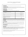
PEAVEY ELECTRONICS CORPORATION LIMITED WARRANTY
Effective Date: July 1, 1998
WWhhaatt TThhiiss WWaarrrraannttyy CCoovveerrss
Your Peavey Warranty covers defects in material and workmanship in Peavey products purchased and serviced in the U.S.A. and Canada.
WWhhaatt TThhiiss WWaarrrraannttyy DDooeess NNoott CCoovveerr
The Warranty does not cover: (1) damage caused by accident, misuse, abuse, improper installation or operation, rental, product modification or neglect; (2) dam-
age occurring during shipment; (3) damage caused by repair or service performed by persons not authorized by Peavey; (4) products on which the serial number
has been altered, defaced or removed; (5) products not purchased from an Authorized Peavey Dealer.
WWhhoo TThhiiss WWaarrrraannttyy PPrrootteeccttss
This Warranty protects only the original retail purchaser of the product.
HHooww LLoonngg TThhiiss WWaarrrraannttyy LLaassttss
The Warranty begins on the date of purchase by the original retail purchaser. The duration of the Warranty is as follows:
Product Category Duration
Guitars/Basses, Amplifiers, Pre-Amplifiers, Mixers, Electronic
Crossovers and Equalizers 2 years *(+ 3 years)
Drums 2 years *(+ 1 year)
Enclosures 3 years *(+ 2 years)
Digital Effect Devices and Keyboard and MIDI Controllers 1 year *(+ 1 year)
Microphones 2 years
Speaker Components (incl. speakers, baskets, drivers,
diaphragm replacement kits and passive crossovers)
and all Accessories 1 year
Tubes and Meters 90 days
[*Denotes additional warranty period applicable if optional Warranty Registration Card is completed and returned to Peavey by original retail purchaser within 90 days of purchase.]
WWhhaatt PPeeaavveeyy WWiillll DDoo
We will repair or replace (at Peavey's discretion) products covered by warranty at no charge for labor or materials. If the product or component must be shipped to
Peavey for warranty service, the consumer must pay initial shipping charges. If the repairs are covered by warranty, Peavey will pay the return shipping charges.
HHooww TToo GGeett WWaarrrraannttyy SSeerrvviiccee
((11))
Take the defective item and your sales receipt or other proof of date of purchase to your Authorized Peavey Dealer or Authorized Peavey Service Center.
OR
((22))
Ship the defective item, prepaid, to Peavey Electronics Corporation, International Service Center, 412 Highway 11 & 80 East, Meridian, MS 39301 or Peavey
Canada Ltd., 95 Shields Court, Markham, Ontario, Canada L3R 9T5. Include a detailed description of the problem, together with a copy of your sales receipt or
other proof of date of purchase as evidence of warranty coverage. Also provide a complete return address.
LLiimmiittaattiioonn ooff IImmpplliieedd WWaarrrraannttiieess
ANY IMPLIED WARRANTIES, INCLUDING WARRANTIES OF MERCHANTABILITY AND FITNESS FOR A PARTICULAR PURPOSE, ARE LIMITED IN DURATION TO THE
LENGTH OF THIS WARRANTY.
Some states do not allow limitations on how long an implied warranty lasts, so the above limitation may not apply to you.
EExxcclluussiioonnss ooff DDaammaaggeess
PEAVEY'S LIABILITY FOR ANY DEFECTIVE PRODUCT IS LIMITED TO THE REPAIR OR REPLACEMENT OF THE PRODUCT, AT PEAVEY'S OPTION. IF WE ELECT TO
REPLACE THE PRODUCT, THE REPLACEMENT MAY BE A RECONDITIONED UNIT. PEAVEY SHALL NOT BE LIABLE FOR DAMAGES BASED ON INCONVENIENCE, LOSS OF
USE, LOST PROFITS, LOST SAVINGS, DAMAGE TO ANY OTHER EQUIPMENT OR OTHER ITEMS AT THE SITE OF USE, OR ANY OTHER DAMAGES WHETHER INCIDENTAL,
CONSEQUENTIAL OR OTHERWISE, EVEN IF PEAVEY HAS BEEN ADVISED OF THE POSSIBILITY OF SUCH DAMAGES.
Some states do not allow the exclusion or limitation of incidental or consequential damages, so the above limitation or exclusion may not apply to you.
This Warranty gives you specific legal rights, and you may also have other rights which vary from state to state.
If you have any questions about this warranty or service received or if you need assistance in locating an Authorized Service Center, please contact the Peavey
International Service Center at (601) 483-5365 / Peavey Canada Ltd. at (905) 475-2578.
Features and specifications subject to change without notice.

Features and specifications subject to change without notice.
Peavey Electronics Corporation • 711 A Street • Meridian • MS • 39301
(601) 483-5365 • FAX (601) 486-1278 • www.peavey.com
©2004 Printed in the U.S.A. 2/04
-
 1
1
-
 2
2
-
 3
3
-
 4
4
-
 5
5
-
 6
6
-
 7
7
-
 8
8
-
 9
9
-
 10
10
-
 11
11
-
 12
12
-
 13
13
-
 14
14
-
 15
15
-
 16
16
-
 17
17
-
 18
18
-
 19
19
-
 20
20
-
 21
21
-
 22
22
-
 23
23
-
 24
24
-
 25
25
-
 26
26
-
 27
27
-
 28
28
-
 29
29
-
 30
30
-
 31
31
-
 32
32


Peavey PV 6 Manual de usuario
- Categoría
- Mezcladores de audio
- Tipo
- Manual de usuario
- Este manual también es adecuado para
en otros idiomas
- français: Peavey PV 6 Manuel utilisateur
- English: Peavey PV 6 User manual
- Deutsch: Peavey PV 6 Benutzerhandbuch
Artículos relacionados
-
Peavey PV 20 Manual de usuario
-
-
Peavey 24FX Mixer Instrucciones de operación
-
-
-
-
-
-
-