1·
Instalación
-Enjuagar bien las tuberías.
-Situar: Agua fría a
la
derecha.
Agua caliente a
la
izquierda.
1a. Mezcladores de repisa (fig.1, 2 y 3)
-No
torsionar los flexibles (28 ó 60-61).
-
En
versiones con desagüe automático
el
pomo {26)
debe descansar sobre
el
grifo cuando el desagüe está
abierto.
1 b.Mezclador de fregadero (fig.3)
-Montar
el
flexible (73) mediante las juntas suministradas
junto con el contrapeso. Se recomienda desmontar
el
codo (72).
1c.Mezcladores empotrables (fig.4)
-Cortar
la
carcasa de plástico (42) a nivel de los azulejos.
-Desmontar el protector (68) y a continuación montar
el
inversor (69).
-Montar
el
rosetón (43 ó 70).
2-Cambio de cartucho (fig. 1)
-Desmontar
la manecilla (1), aflojando el tornillo (2) y
sacar la caperuza (3).
Desenroscar
el
anillo (6).
-Cambiar
el
cartucho (7).
3-Limitación campo temperatura y
caudal (fig. 5)
-Posicionando el anillo (5),
se
limita
el
giro hacia caliente
o frío (pos.2) limitando solo
el
campo de temperatura.
-Girando
el
anillo (5) 180º
se
reduce el ángulo de
apertura (pos.3) limitando
el
caudal máximo
al
50%.
-Posicionando el anillo (5) según (pos.
4)
se limita
el
caudal máximo al 50% y el campo de temperatura.
4-Mantenimiento
-Limpiar solo con detergente líquido.
-No utilizar ningún tipo de estropajo.
-Enjuagar y secar después de cada uso.
-Descalcificar periódicamente los aireadores (12)
introduciendo
el
bloque interior
en
vinagre al menos
durante 1 hora.
S-Desmontaje inversor (fig. 6)
-Desmontar
el
antirretorno (si existe).
-Desmontar el pomo (30) fijando
el
eje mediante una
llave Alien de
4.
-Retirar
el
manguito
(31
).
-Desmontar
el
inversor (32) con
su
junta.
-Eliminar
el
resorte
en
caso de presión
de
servicio
inferior a 0,5 bar.
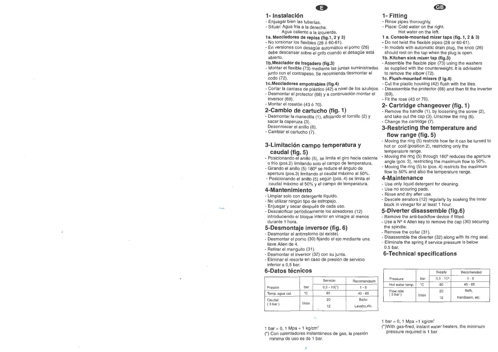
6-Datos técnicos
Servicio
Recomendado
Presión bar 0,5
-10(')
1-5
Temp. agua cal.
'C
80
45-65
Caudal 20
Baño
( 3
bar)
1/min
Lavabo, etc.
12
'
1
bar=
O,
1 Mpa
.,
1 kg/cm'
(*) Con calentadores instantáneos de gas, la presión
mínima de uso es de 1 bar.
1- Fitting .
-Rinse pipes thoroughly.
-Place: Cold water on the right.
Hot water on the left.
1
a.
Console-mounted mixer taps (fig. 1, 2 & 3)
-Do not twist the flexible pipes (28 or 60-61
).
-
In
models with automatic drain plug, the knob (26)
should rest
on
the tap when the plug
is
open.
1 b. Kitchen sink mixer tap (fig.3)
-Assemble the flexible pipe (73) using the washers
as supplied with the counterweight. lt is advisable
to remove the elbow (72).
1c. Flush·mounted mixers (f lg.4)
-Cut
the plastic housing (42) flush with the
ti
les.
-Disassemble the protector (68) and then lit the inverter
(69).
-Fit the rose (43 or 70).
2·
Cartridge changeover (fig. 1)
-Remove the handle (1), by loosening the screw (2),
and take out the cap (3). Unscrew the ring (6).
-Change the cartridge (7).
3-Restricting the temperature and
flow range (fig. 5)
-Moving the ring (5) restricts how lar it can be turned to
hot or cold (position 2), restricting only the
temperatura range.
-Moving the ring (5) through 180º reduces the aperture
angle (pos. 3), restricting the maximum flow to 50%.
-Moving the ring (5) to (pos.
4)
restricts the maximum
flow to 50% and also the temperatura range.
4-Maintenance
-Use only liquid detergent for cleaning.
-Use no scouring pads.
-Rinse and dry alter use.
-Descale aerators (12) regularly by soaking the inner
block
in
vinegar for at least 1 hour.
5-Diverter disassemble (fig.6)
-Remove the anti-backflow device if fitted.
-Use a Nº 4 Allen key to remove the cap (30) securing
the spindle.
-Remove the collar (31).
-Disassemble the diverter (32) along with its ring seal.
-Eliminate the spring if service pressure
is
below
0.5 bar.
6-Technical specifications
Supply Recomendad
Pressure
bar
0.5-
10*
1-5
Hot water temp.
'C
80
45-65
Flow rate 20
Bath,
( 3
bar)
1/min
12 Handbasin,
etc.
1
bar=
O,
1 Mpa
»1
kg/cm'
(*)With gas-fired, instan! water heaters, the minimum
pressure required
is
1 bar


