Barrette HEAVY-DUTY DROP ROD Instrucciones de operación
- Tipo
- Instrucciones de operación

WEB-REV 2.21
HEAVY-DUTY DROP ROD
Read all instructions prior to installing product.
Refer to manufacturers safety instructions when operating any tools.
To register your product, please visit: barretteoutdoorliving.com
Installation Instructions
English ...................................................................................1
Français .................................................................................5
Español .................................................................................. 9

2
To obtain and review a copy of the warranty please visit: barretteoutdoorliving.com. You may also contact us at
1-800-336 2383 or email [email protected]
Safety Glasses
Pencil
Level
Tape Measure
Drill
Square or Phillips Driver Bit
TOOLS NEEDED:BEFORE YOU BEGIN:
WARNING:
• Improper installation of this product can result in personal injury. Always wear safety goggles when
cutting, drilling and assembling the product.
• Incorrect installation may cause harm to the gate or individual.
NOTICE:
• DO NOT attempt to assemble the kit if parts are missing or damaged.
• DO NOT return the product to the store, for assistance or replacement parts call: 1-800-336-2383.
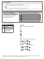
Component List:
Please read the instructions completely
before assembling. Retain manual and
your dated sales slip for future reference
or warranty claims.
QTY Description
1 Heavy-Duty Drop Rod
2 Drop rod brackets
8 11⁄4" Self-Drilling
Square/Phillips Combo
Pan Head Screws
Drop Rod Brackets
Screws
Heavy-Duty Drop Rod

3
1.
2.
3.
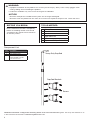
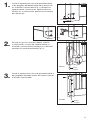
Mount the lower drop rod bracket two inches from
the bottom edge of the gate with the 4 supplied
screws (Fig. 1). Mark pilot holes through screw
holes (a), then drill using 3/32" drill bit (b).
Thread the rod through the upper bracket then
through the installed lower bracket into the receiver
hole (your choice: dug, excavated or drilled) (Fig. 2).
Fig. 2
Fig. 3
With the tabs in the locked position, attach the top
bracket to the gate so that the drop rod does not
drag when gate is opened or closed.
2"
a) b)
Fig. 1
Receiver
Hole
Open
Receiver
Hole
Closed

4
Barrette Outdoor Living
545 Tilton Rd, Egg Harbor City, NJ. 08215
barretteoutdoorliving.com • (800) 336-2383
REV 2.21

5
BARRE DE FERMETURE
DE QUALITÉ INDUSTRIELLE
Lire toutes les instructions avant d’installer le produit.
Consulter les consignes de sécurité du fabricant lors de l’utilisation des outils.
Pour enregistrer votre produit, veuillez visiter: barretteoutdoorliving.com
Instructions d’installation
English ...................................................................................1
Français .................................................................................5
Español .................................................................................. 9
WEB-REV 2.21

6
Pour obtenir et examiner une copie de la garantie, visiter: barretteoutdoorliving.com. Vous pouvez également
nous appeler au 1-800-336 2383 ou nous envoyer un courriel à [email protected]
AVERTISSMENT:
• L’installation incorrecte de ce produit peut entraîner des blessures. On doit troujours porter des lunettes
de sécurité lors de la coupe, du perçage et de l’assemblage du produit.
• Une installation incorrecte est susceptible de causer des dommages
à la barrière ou des blessures à la personne qui fait l’installation.
AVIS:
• Ne pas tenter de monter le kit si des pièces sont manquantes ou endommagées
• ne pas retourner le produit au magasin ; pour une aide ou un remplacement, faire le numéro suivant:
1-800-336-2383.
Liste des composantes:
Lunettes de sécurité
Crayon
Niveau
Mètre à ruban
Perceuse
Tournevis étoile (Phillips) ou carré
OUTILS NÉCESSAIRES:AVANT DE COMMENCER:
Veuillez lire les instructions avant
l’assemblage. Conserver le manuel
et votre reçu de caisse daté pour de
futures références ou de réclamations
de garantie.
QTE Description
1 Barre de fermeture de
qualité industrielle
2 Supports de barre
de fermeture
8 Vis autotaraudeuses
combo carré/cruciforme
de 31.75 mm à tête
cylindrique
Vis
Barre de fermeture de qualité industrielle
Supports de barre de fermeture

7
1.
2.
3.
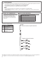
Monter le support inférieur de la barre de ferme-
ture à deux pouces du bord inférieur du portillon
avec les 4 vis fournies (Fig. 1). Marquer des trous
pilotes àtravers les trous de vis (b). Puis percer à
l’aide d’une mèche de 2.38 mm (b).
Thread the rod through the upper bracket then
through the installed lower bracket into the receiver
hole (your choice: dug, excavated or drilled) (Fig. 2).
Fig. 2
Fig. 3
With the tabs in the locked position, attach the top
bracket to the gate so that the drop rod does not
drag when gate is opened or closed.
50.8mm
a) b)
Fig. 1
Trou
récepteur
Ouvert
Trou
récepteur
Fermé

8
Barrette Outdoor Living
545 Tilton Rd, Egg Harbor City, NJ. 08215
barretteoutdoorliving.com • (800) 336-2383
REV 2.21

9
WEB-REV 2.21
CERROJO DE
GRAVEDAD
Lea todas las instrucciones antes de instalar el producto.
Consulte las instrucciones de seguridad del fabricante al utilizar herramientas
Para registrar su producto, visite: barretteoutdoorliving.com
Instrucciones de instalación
English ...................................................................................1
Français .................................................................................5
Español .................................................................................. 9

10
Para obtener y revisar una copia de la garantía, visite: barretteoutdoorliving.com. También puede contactarnos
en: 1-800-336 2383 o correo electrónico [email protected]
AVERTENCIA:
• La instalación incorrecta de este producto puede provocar lesiones corporales. Utilice siempre gafas de
seguridad al cortar, taladrar y ensamblar el producto.
• La instalación incorrecta puede causar daños a la puerta o a personas.
AVISO:
• No intente instalar el kit si faltan piezas o las piezas están dañadas.
• No devuelva el producto a la tienda; para solicitar ayuda o piezas de repuesto llame al: 1-800-336-2383.
Lista de los componentes:
HERRAMIENTAS QUE SE REQUIEREN:ANTES DE COMENZAR:
Lea las instrucciones en su totalidad
antes de comenzar a instalar. Conserve
el manual y el recibo de compra
fechado para futura referencia o
reclamos de garantía.
Gafas de protección
Lápiz
Nivel
Cinta métrica
Taladro
Punta de desarmador cuadrado o de estrella
CTD Descripción
1 Tranca de gravedad
reforzada
2 Soportes para tranca
de gravedad
8Tornillos autorroscantes
de cabeza troncocónica
de hueco cuadrado/
Phillips combinado
de 31.75 mm
Manija
Tranca de gravedad reforzada
Soportes para tranca de gravedad

11
1.
2.
3.
Instale el soporte para tranca de gravedad inferior
a dos pulgadas del borde inferior de la puerta con
los 4 tornillos suministrados (Fig. 1). Marque los
agujeros piloto a través de los agujeros para los
tornillos (a). A continuación, perfore con una broca
de 2.38 mm (b).
Ensarte la tranca a través del soporte superior,
a continuación, a través del soporte inferior ya
instalado y hasta el oricio receptor (a su elección:
extraído, excavado o perforado) (Fig. 2).
Fig. 2
Fig. 3
Instale el soporte para tranca de gravedad inferior a
dos pulgadas del borde inferior de la puerta con los
4 tornillos suministrados.
a) b)
Fig. 1
Oricio
receptor
Abierto
Oricio
receptor
Cerrada
50.8mm

Barrette Outdoor Living
545 Tilton Rd, Egg Harbor City, NJ. 08215
barretteoutdoorliving.com • (800) 336-2383
REV 2.21
-
 1
1
-
 2
2
-
 3
3
-
 4
4
-
 5
5
-
 6
6
-
 7
7
-
 8
8
-
 9
9
-
 10
10
-
 11
11
-
 12
12


Barrette HEAVY-DUTY DROP ROD Instrucciones de operación
- Tipo
- Instrucciones de operación
en otros idiomas
Artículos relacionados


Otros documentos
-
Barrette Outdoor Living 73044983 Instrucciones de operación
-
-
-
Barrette Outdoor Living 73025673 Instrucciones de operación
-
-
-
Boerboel 73014251 Instrucciones de operación