
®
Part. LE05334AD-09/13-01 GF
Daker DK 1, 2, 3 kVA
Manuel d’installation • Installation manual

2
FRANÇAIS 3
ENGLISH 23
ITALIANO 43
DEUTSCH 63
ESPAÑOL 83
PУСCKИЙ 103
FR
FR
IT
DE
ES
EN
Daker DK 1, 2, 3 kVA
®
RU

FR
Daker DK 1, 2, 3 kVA
3
Indice
1 Introduction 4
2 Conditions d’utilisation 4
3 Panneau LCD 5
4 Installation 8
5 Logiciel d’autodiagnostic ups communicator 17
6 Changement batteries 18
7 Dysfonctionnements possibles 20
8 Caractéristiques techniques 21

4
Ce manuel contient les informations concernant l’utilisation des modèles Daker DK 1, 2, 3 kVA.
Il est recommandé de lire attentivement ce manuel avant de procéder à l’installation de l’onduleur
et de respecter scrupuleusement les instructions ci-dessous.
Les UPS Daker DK 1, 2, 3 kVA sont conçus pour une utilisation domestique ou industrielle.
Ils ne sont pas conformes aux réglementations pour appareils électriques médicaux.
En cas de problème sur l’UPS, il est recommandé de lire le présent manuel avant de contacter le
service d’assistance technique ; la section “Éventuels problèmes et solutions” permet en effet de
résoudre la plupart des problèmes rencontrés durant l’utilisation l’UPS.
1 Introduction
• L’UPS est conçu pour alimenter des appareillages de traitement de données ; la charge appliquée
ne doit pas dépasser celle indiquée sur l’étiquette apposée au dos de l’UPS.
• Le bouton ON/OFF de l’UPS n’isole pas électriquement les parties internes. Pour isoler l’UPS, le
débrancher de la prise d’alimentation du secteur.
• Ne pas ouvrir le conteneur de l’UPS car des parties peuvent être sous tension dangereuse à l’in-
térieur, même si la prise du secteur est débranchée. Dans tous les cas, à l’intérieur de l’onduleur,
aucune pièce ne peut être réparée par l’utilisateur.
• Le panneau frontal de contrôle est prévu pour des opérations manuelles ; ne pas appuyer sur le
panneau avec des objets pointus ou coupants.
• Les UPS Daker DK ont été conçus pour fonctionner dans un environnement fermé, propre, sans
liquide inflammable ou substances corrosives et non excessivement humide.
• Ne pas positionner l’onduleur à proximité d’appareils qui génèrent de forts champs électroma-
gnétiques et/ou d’appareils sensibles aux champs électromagnétiques (moteurs, disquettes,
haut-parleurs, transformateurs, écrans, video, etc...).
• Ne pas verser de liquides sur ou dans l’UPS.
• Éviter d’exposer l’UPS à la lumière directe du soleil ou à proximité de sources de chaleur.
• Maintenir toujours propres les fentes d’aération et ne pas les obstruer afin de permettre la dissi-
pation de la chaleur interne de l’UPS.
• Brancher l’UPS à une installation équipée d’un conducteur de mise à la terre.
• Ne pas utiliser l’UPS pour alimenter des imprimantes laser à cause de leur courant de démarrage
élevé.
• Ne pas utiliser l’UPS pour alimenter des appareils électroménagers comme les sèche-cheveux,
les climatiseurs, les réfrigérateurs, etc.
2 Conditions d’utilisation
®

FR
Daker DK 1, 2, 3 kVA
5
3 Panneau LCD
1. Panneau LCD.
2. Le LED vert allumé indique que l’alimentation sur secteur est comprise entre 160 et 288 Vca.
3-4. Les leds verts indiquent que sont présentes les sorties programmables Outlet 1 et Outlet 2.
5. Le LED orange indique que le By-pass est actif.
6. LED d’alarme UPS.
7. Bouton d’allumage UPS/Désactivation avertisseur sonore.
8. Bouton d’extinction UPS.
9. Bouton menu d’accès aux fonctions spéciales, log in/out.
10. Bouton de sélection de la page suivante.
11. Bouton de sélection de la page précédente ou de changement réglage.
12. Bouton de conrmation de sélection.
2 3 4 5 6
7 8 9 10 11 12
1

6
®
Symboles écran LCD
3 Panneau LCD
Réf. Symbole Description
1 Alimentation sur secteur
2 Niveau batterie able
3 Batterie endommagée
4 Surcharge
5 Erreur de branchement terre
6 Fonctionnement en Service Mode
7 UPS éteint
8 UPS en alarme
9 Schéma de fonctionnement UPS
10 Visualisation mesures
11 Indique le paramètre mesuré
22 Batterie faible ou à changer
23 Court-circuit en sortie
24 Courant excessif variateur fréquence
25 Surchaue
26 Surcharge en sortie
27 Autres alarmes
LINE
OFF
FAIL
Er05
Er06
Er10
Er11
Er12
Er**

FR
Daker DK 1, 2, 3 kVA
7
Panneau arrière 230V
13. Port de communication USB
14. Port de communication RS232
15. Coupure d’urgence alimentation (EPO)
16. Logement pour cartes de communication
en option
17. Connecteur expansion autonomie
18. Connexions d’entrée
19. Connexions de sortie
20. Sorties programmables
21. Interrupteurs de protection d’entrée
22. Ventilateurs de refroidissement
23. Interrupteurs de protection de sortie
24. Interrupteurs de protection des sorties
programmables
INTERFACE
INPUT
BREAKER
AC INPUT
AC OUTPUT
12
DC 72V
G
G
+
-
EPO
AB
1/2
OUTPUT BREAKER
1
2
AC OUTPUT
EPO
DC 36V
AC INPUT
INPUT
BREAKER
INTERFACE
G
G
++
-
13
14
15
1617 18
19202122
INTERFACE
INPUT
BREAKER
AC INPUT
AC OUTPUT
12
DC 72V
G
G
+
-
EPO
3 100 50
13
14
15
1617 1821
1920
3 100 51
22
13
14
15
1617 1821
1920
3 100 52
22
24 23

8
®
4 Installation
Contrôler le contenu de l’emballage :
• Mode d’emploi
• Câble de branchement charges sortie
• Câble d’entrée
• Câble de communication RS232
• Câble de communication USB
• Accessoires de configuration Tower/rack
A1 A2 - Optional
A4
A3 - Optional
B2B1
4 pcs 1 pcs 1 pcs
1 pcs
2 pcs 2 pcs
S1
2 pcs
M3
6.0
±1.0mm
S2
8 pcs
M3
6.0
±1.0mm
S3
6 pcs
M4
8.0
±1.0mm

FR
9
Daker DK 1, 2, 3 kVA
Configuration tower
A1
A1
A1
A1
A3
A2
Step 1
Step 2

10
®
4 Installation
UPS + armoire batterie (option)
A4
Step 1
Step 2

FR
Daker DK 1, 2, 3 kVA
11
Configuration rack 19”
B2
B1
S3
90°
Step 1
Step 2
Step 3
Step 4

12
®
4 Installation
Step 5
Step 6

FR
Daker DK 1, 2, 3 kVA
13
Au dos de l'UPS de continuité sont prévus les branchements suivants :
• Prises de sortie [19] et connecteur d’entrée [18] : à ces deux connecteurs, brancher le câble
d’alimentation et les câbles de sortie fournis à cet effet.
• Prise de branchement interface série de l’ordinateur type RS232 (9 pôles femelle) [14] : à utiliser
dans le cas où l’on souhaiterait utiliser le logiciel de diagnostic et gestion extinction.
• Prise de branchement interface USB [13] : à utiliser dans le cas où l’on souhaiterait connecter
l’UPS par l’intermédiaire du câble USB.
• Connexion prévue pour batteries supplémentaires [17].
AVERTISSEMENT
Pour des raisons de sécurité, il est recommandé de ne pas modifier les câbles fournis ; en
outre, il est nécessaire de s’assurer que le prise de secteur à laquelle le groupe de continuité
est branché dispose d'une bonne connexion au circuit de terre comme requis par la norme.
AVERTISSEMENT
La prise d’alimentation sur secteur ou le dispositif de sectionnement doit être installé à
proximité de l’appareillage et doit être facile d’accès.
Procéder à l’installation comme suit :
1) Positionner l'UPS de telle sorte que les fentes de ventilation ne soient pas obstruées.
2) Au connecteur d’entrée [18], brancher le câble d’alimentation et les câbles de sortie aux
connecteurs correspondants [19].
3) Brancher les charges aux câbles de sortie en s’assurant que les interrupteurs des différents
dispositifs sont sur la position Off.
4) Brancher la fiche d’alimentation à une prise de courant adaptée à la tension et au courant
requis.
Allumage
1) Fermer l’interrupteur de protection entrée situé au dos de l’UPS [21]. L’UPS s’allume et
les VOYANTS verts , et indiquent que l’entrée de secteur l’entrée de by-pass sont
normales. L’écran LCD indique OFF au bout de quelques secondes.
2) A présent, l’UPS est en Mode By-pass et effectue automatiquement le self-test. Si aucun
message d’anomalie ne s’affiche, cela indique que le pré-allumage de l’UPS a été correctement
effectué ; le chargeur entame la charge des batteries.
3) Appuyer sur la touche d’allumage de l’UPS [7] pendant 3 secondes. L’avertisseur sonore
émit deux sons et l’écran change d’état en passant à la modalité RUN.
4) L’UPS est à nouveau en modalité self-test. L’écran affiche le message TEST et l’UPS reste en
modalité batteries pendant quatre secondes environ.
5) En cas d’échec du self-test, un code ou un message d’erreur s’affiche sur l’écran.
6) Une fois ces opérations effectuées, l’allumage de l’UPS est complet. S’assurer que l’UPS est
branché sur secteur pour une charge d’au moins 8 heures et que les batteries sont entièrement
chargées avant de brancher la charge à protéger.

14
®
4 Installation
Shutdown
7) Appuyer sur la touche d’extinction [ 8 ] pendant cinq secondes. La sortie du variateur
s’éteint et la charge est alimentée à travers le By-pass.
8) Ouvrir l’interrupteur d’alimentation sur le tableau électrique.
9) Ensuite, l’UPS est entièrement éteint.
Fonctions spéciales
L'UPS est doté de deux sorties programmables pour les charges les moins critiques. Ces prises
peuvent être désactivées ou temporisées durant le fonctionnement sur batteries, pour maintenir
une alimentation de qualité pour les charges les plus critiques.
Il est possible d’accéder à cette fonction et à d’autres fonctions en téléchargeant gratuitement le
logiciel “UPS Setting tool” sur le site www.ups.legrand.com.
Données par défaut et fonctions spéciales
1) A l’issue du bon allumage de l’UPS, appuyer sur le bouton Fonctions spéciales pour passer
à l’option montrée sur la figure P1.
P1
P2
2) Appuyer sur la touche pour modifier les réglages de l’UPS. Sur l’écran, s’affichent
successivement : figure P1 (Avertisseur sonore) figure Q1 (Self-test) figure R1 (Tension de
By-pass) figure S (Fréquence de sortie synchronisée) figure T (Tension de sortie du inverseur)
figure U1 (Modalités de fonctionnement) figure V (Réglage fin de la tension de sortie).
Q1
Q2

FR
Daker DK 1, 2, 3 kVA
15
R1
R2
S
T
U1
U2
U3
V

16
®
4 Installation
3) Appuyer sur la touche “Haut” pour régler les fonctions spéciales. Les fonctions incluent
Avertisseur sonore ON (figure P1), Avertisseur sonore OFF (figure P2, alarme désactivée en cas
de signaux provenant de l’UPS) et Self-test ON (figure Q1) ou OFF (figure Q2). L’UPS effectue
ensuite le test des batteries pendant 10 secondes). Si le Self-test est réussi, sur l’écran, s’affiche la
figure W ; différemment, s’affiche la figure D et, dans le même temps, un message d’erreur.
W
Réglages UPS par défaut et Réglages Alternatifs
1) S’assurer que l’UPS n’est pas allumé, par exemple qu’il n’est pas en Line Mode ni en BackUp
Mode. Appuyer simultanément sur la touche “ON” et sur la touche “Bas” pendant quatre
secondes environ. L’avertisseur sonore émet deux bips et sur l’écran, s’affiche la figure P1 pour
indiquer que l’UPS est en “modalité configuration”.
2) Pour faire défiler les réglages disponibles, utiliser les touches “Haut” et “Bas” .
3) A l’exception de l’avertisseur sonore (figures P1 et P2) et du Self-test (figures Q1 et Q2), tous les
autres réglages peuvent être modifiés en appuyant sur la touche “Haut” .
4) Les figures R1 et R2 indiquent l’intervalle de tension pour le by-pass. Il peut être compris entre
180 et 260 Vca pour les systèmes à 220 Vca, entre 90 et 130 Vca pour les systèmes à 110 Vca, entre
194 et 260 Vca pour les systèmes à 220 Vca ou entre 97 et 130 Vca pour les systèmes à 110 Vca.
5) La figure S indique l’intervalle de fréquence de by-pass pour la sortie du variateur. Les réglages
possibles sont les suivants : ±3 Hz et ±1 Hz.
6) La figure T indique la tension de sortie du variateur. Les valeurs possibles sont 200, 208, 220, 230
et 240 V pour les systèmes à 220 Vca, et 100, 110, 115, 120 et 127 V pour les systèmes à 110Vca.
7) Les figures U1, U2 et U3 indiquent les modalités de fonctionnement de l’UPS. Les valeurs
possibles sont Online, sortie fixe à 50 Hz et sortie fixe à 60 Hz.
8) La figure V indique l’ajustement fin de la sortie du variateur, les valeurs possibles sont 0%, +1%,
-1%, +2%, -2%, +3% et -3%.
9) Une fois les paramètres voulus réglés, il est nécessaire d’appuyer sur la touche “Enter” ,
quand l’écran affiche la figure X, pour sauvegarder toutes les modifications. Les modifications
sont ensuite actives après arrêt et rallumage de l’UPS. Ensuite, l’écran affiche à nouveau la figure
initiale précédant celle des réglages. Après le rallumage, l’écran affiche la figure affichée avant la
modification des réglages (figure B).
B

FR
Daker DK 1, 2, 3 kVA
17
X
10) Éteindre l’UPS et ouvrir l’interrupteur en amont.
11) A ce stade, les réglages ont été sauvegardés.
Connexion
L’UPS est doté d’interfaces standard RS232 et USB grâce auxquelles il est possible d'accéder, par
l’intermédiaire d’un ordinateur, à une série de données relatives au fonctionnement et à l’historique
de l’UPS. La fonction est utilisable par l’intermédiaire du programme d’interface pour WINDOWS (*),
en connectant un port sériel du PC aux prises d’interface [Indicare numero riferimento] présent au
dos de l’UPS, à l’aide d’un câble RS 232 ou USB.
5 Logiciel d’autodiagnostic UPS communicator
Sur le site www.ups.legrand.com, il est possible de télécharger gratuitement un logiciel d’autodia-
gnostic pour WINDOWS (16 et 32 bits) et Linux.
Ce logiciel fournit les fonctions suivantes :
- Visualisation de toutes les données de fonctionnement et de diagnostic en cas de problème.
- Configuration des fonctions spéciales.
- Extinction automatique de l’ordinateur local (avec logiciel d’exploitation Windows et Linux).
* Windows est une marque enregistrée de Microsoft Corporation.

18
®
6 Changement batteries
Step 1
Step 2

FR
Daker DK 1, 2, 3 kVA
19
Step 3
Step 4
3 100 50
Step 4
3 100 51
3 100 52

20
®
7 Dysfonctionnements possibles
L’UPS marche toujours avec alimentation batterie :
• la tension de secteur n’est pas présente ;
• la tension de secteur est hors des limites de la plage de l’UPS ;
• le câble d’alimentation n’est pas correctement branché à la prise d’alimentation.
• l’interrupteur magnétothermique est en position relevée.
• la prise d’alimentation est défectueuse.
L’UPS signale une surcharge :
• des charges supplémentaires, en plus de celles normalement connectées, ont été involontairement
branchées ;
• vérifier toutes les charges branchées en sortie.
L’UPS ne fonctionne pas avec alimentation batterie (il se bloque ou signale immédiatement une
réserve autonomie):
• l’UPS a marché pendant longtemps sans alimentation de secteur et n’a pas pu recharger sa
batterie. La recharger pendant au moins 6 heures en branchant l’onduleur à l’alimentation
secteur, allumé.
• la batterie est déchargée à cause d’une longue période d’inactivité de l’UPS. La recharger
pendant au moins 6 heures en branchant l’onduleur à l’alimentation secteur.
• la batterie s’est épuisée à cause de son utilisation fréquente, des conditions environnementales
ou du dépassement de la durée moyenne de vie, elle doit être remplacée.
L’UPS ne fournit pas de tension en sortie:
• vérifier que les charges sont correctement branchées aux prises de sortie.

FR
Daker DK 1, 2, 3 kVA
21
8 Caractéristiques techniques
SPÉCIFICATIONS DE CONSTRUCTION 3 100 50 3 100 51 3 100 52
Poids 16 Kg 29,5 Kg 30 Kg
Dimensions L x H x P en millimètres 440 x 88 x 405 440 x 88 x 650 440 x 88 x 650
Protections électroniques
Contre les surcharges et les courts-circuits
Blocage du fonctionnement dû à la fin
d’autonomie et à la surchauffe
Extinction automatique due à l’activation
des protections
Spécifications environnementales
Température de fonctionnement de 0 à +40 °C
Humidité relative pour le fonctionnement de 20 à 80% sans condensation
Niveau de protection suivant IEC529 IP20
Niveau de bruit à 1 mètre < 50 dBA
Caractéristiques électriques d’entrée
Tension nominale d’entrée 230 V
Tension d’entrée de 160 V à 288 V
Fréquence nominale d’entrée 50 ou 60 Hz ± 5Hz
Courant maximum d’entrée 5,2 Arms 10,4 Arms 15 Arms
Nombre des phases d’entrée monophasé
Forme d’onde de sortie
Avec fonctionnement batterie sinusoïdale
Type de fonctionnement on line - conversion double
Caractéristiques électriques de sortie avec alimentation secteur
Tension nominale de sortie 230 V ± 1%
Puissance active de sortie avec charge nominale 800W 1,6 kW 2,4 kW
Puissance apparente de sortie
avec charge nominale
1kVA 2 KWA 3 KWA
Capacité de surcharge
105% sans interruption
120% pendant 30 secondes
150% pendant 10 secondes
Nombre des phases de sortie monophasé

22
®
8 Caractéristiques techniques
SPÉCIFICATIONS DE CONSTRUCTION 3 100 50 3 100 51 3 100 52
Caractéristiques électriques de sortie avec alimentation
Tension nominale de sortie 230 V ± 1%
Fréquence de sortie 50/60 Hz ± 0.1%
Puissance active de sortie
sur charge non linéaire
800W
1,6kW 2,4kW
Puissance apparente de sortie
sur charge non linéaire
1kVA 2kVA 3kVA
Fonctionnement avec batterie
Autonomie 10 min. 10 min. 8 min.
Temps de recharge 4-6 heures à 80% de la charge
Données techniques et quantité de batteries
3 sans
entretien,
au plomb,
scellée
12V 7,2Ah
6 sans
entretien,
au plomb,
scellée
12V 7,2Ah
6 sans
entretien,
au plomb
acide, scellée
12V 9Ah
Normes
Compatibilité électromagnétique
immunité - émissions
Répondant aux normes EN 62040 - 2
Sécurité électrique Répondant aux normes EN 62040-1
Prestations caractéristiques Répondant aux normes EN 62040 -3
ATTENTION
Les batteries sont considérées comme des déchets dangereux et doivent être éliminées
suivant la réglementation en vigueur.

EN
23
Daker DK 1, 2, 3 kVA
Index
1 Introduction 24
2 Conditions of use 24
3 LCD Panel 25
4 Installation 28
5 UPS communicator self-diagnostic software 37
6 Battery replacement 38
7 Possible malfunctioning 40
8 Technical features 41

24
This manual contains information for users of the Daker DK 1, 2, 3 kVA models.
You are advised to read this handbook carefully before installing your uninterruptible power sup-
ply, meticulously following the instructions given herein.
The UPS Daker DK is only been made for civil or industrial use; it is not in conformity with the stan-
dards for electro-medical equipment.
In case of problems with the UPS, please read this manual before contacting technical support;
The “Troubleshooting” section can in fact help resolving most of the problems encountered while
using the uninterruptible power supply.
1 Introduction
• The UPS has been designed for the power supply of the data processing equipment; The load
applied must not exceed the one indicated on the rear label of your UPS.
• The ON/OFF button of your UPS does not electrically isolate the internal parts. To isolate your
UPS unplug it from the mains power socket.
• Do not open the UPS container since there may be parts inside with dangerously high voltage
even when the mains plug is disconnected; there are no parts inside that the user can repair.
• The front control panel is provided for manual operations; Do not press on the panel with sharp
or pointed objects.
• The UPS Daker DK has been designed to work in closed, clean rooms where there are no inflam-
mable liquids or corrosive substances and where it is not too damp.
• Do not place near equipments that generate strong electro-magnetic fields and/or near equi-
pments that are sensible to electro-magnetic fields. (engines, floppy disks, speakers, adapters,
monitors, video, etc...)
• Do not pour any liquid on the UPS or inside the UPS.
• Do not place the UPS in humid environment or near liquid, such as water, chemical solution…
• Do not expose the UPS to the direct sunlight or any heat sorces.
• Keep the ventilation slits clean to dissipate the heat of the UPS.
• Use grounded power cable to connect the UPS to the mains supply.
• Do not plug laser printers into the UPS because of their high start-up current.
• Do not plug house electric equipments, such as hair dryer,air conditioner, and refrigerator into
the UPS outlets.
2 Conditions of use
®

EN
25
Daker DK 1, 2, 3 kVA
3 LCD Panel
1. LCD Panel
2. The green LED on steady indicates that the power supply network is within the 160-288 Vac
range.
3-4. The green LEDs indicate that the programmable Outlets 1 and 2 are present.
5. The orange LED indicates that the Bypass is active.
6. UPS alarm LED
7. UPS power on/buzzer silencing pushbutton
8. UPS power o pushbutton
9. Special functions access menu pushbutton, log in/out
10. Following screen selection pushbutton
11. Previous screen selection, or settings change pushbutton
12. Selection conrmation pushbutton
2 3 4 5 6
7 8 9 10 11 12
1

26
®
Display LCD symbols
3 LCD Panel
Item Symbol Description
1 Line source
2 Low battery level
3 Battery damaged
4 Overload
5 Earth connection error
6 Service Mode operation
7 UPS o
8 UPS alarm
9 UPS operation diagram
10 Measurements display
11 It indicates which parameter is being measured
22 Battery insucient or needing replacing
23 Short circuit on the output
24 Excessive inverter current
25 Overtemperature
26 Overload on the output
27 Other Alarms
LINE
OFF
FAIL
Er05
Er06
Er10
Er11
Er12
Er**

EN
Daker DK 1, 2, 3 kVA
27
Rear panel 230V
13. USB Port
14. RS-232 Port
15. Emergency Power O (EPO) Dry Contact
Signal inputs
16. Communication Card Options Slot
17. External Battery Connector
18. AC power connection socket
19. AC Outlets
20. Two programmable outlets
21. Utility Input circuit breaker
22. Cooling Fans
23. Output circuit breaker for two outlets
24. Output circuit breaker for two
programmable outlets
INTERFACE
INPUT
BREAKER
AC INPUT
AC OUTPUT
12
DC 72V
G
G
+
-
EPO
AB
1/2
OUTPUT BREAKER
1
2
AC OUTPUT
EPO
DC 36V
AC INPUT
INPUT
BREAKER
INTERFACE
G
G
++
-
13
14
15
1617 18
19202122
INTERFACE
INPUT
BREAKER
AC INPUT
AC OUTPUT
12
DC 72V
G
G
+
-
EPO
3 100 50
13
14
15
1617 1821
1920
3 100 51
22
13
14
15
1617 1821
1920
3 100 52
22
24 23

28
®
4 Installation
Check for the following standard package contents:
• User Manual
• 2 IEC output cables (for UPS with IEC sockets only)
• detached AC Input Power cable (for UPS with IEC sockets only)
• RS-232 communication cable
• USB communication cable
• Tower/Rack Accessories Kit as below:
A1 A2 - Optional
A4
A3 - Optional
B2B1
4 pcs 1 pcs 1 pcs
1 pcs
2 pcs 2 pcs
S1
2 pcs
M3
6.0
±1.0mm
S2
8 pcs
M3
6.0
±1.0mm
S3
6 pcs
M4
8.0
±1.0mm

EN
Daker DK 1, 2, 3 kVA
29
Tower configuration setup
A1
A1
A1
A1
A3
A2
Step 1
Step 2

30
®
4 Installation
UPS + battery cabinet (optional)
A4
Step 1
Step 2

EN
Daker DK 1, 2, 3 kVA
31
B2
B1
S3
90°
Step 1
Step 2
Step 3
Step 4

32
®
4 Installation
Step 5
Step 6

EN
Daker DK 1, 2, 3 kVA
33
On the rear of the uninterruptible power supply are the following connections:
• Output sockets [19] input connector [18]: connect to these connectors the power cable and the
output cables included.
• Socket for connecting computer serial interface RS232 (9 female pins) [14]: required when using
the diagnostic and shutdown management software.
• Socket for USB interface connection [13]: to be used when connecting the UPS using a USB cable.
• Presetting for the connection of additional batteries [17].
WARNING
For safety reasons it is advised not to modify the cables supplied; it is also necessary to make
sure that that the mains socket the uninterruptible power supply is connected to is fitted
with a safe connection to the earth system, and appropriate protection in accordance with
current regulations.
WARNING
The mains supply socket, or the disconnection device, must be installed nearby the
equipment, and must be easily accessible.
Proceed to the installation as follows:
1) Position the uninterruptible power supply so that the vents are not obstructed.
2) Connect the input connector [18], the power cable, and the output cables to the appropriate
connectors [19].
3) Connect the loads to the output cables, ensuring that the switches of the various users are off.
4) Connect the power supply plug to a power socket with suitable voltage and current.
Start
1) Switch on the power breaker [ 21 ] of the distribution panel. Then the UPS will start up. Green
LEDs , and and show that the Utility and Bypass inputs are normal. The LCD will
display OFF after few seconds.
2) The UPS is in Bypass Mode now. It will proceed to self-test automatically. If no abnormal message
appears then the pre-startup of the UPS was successful and the charger starts to charge the
batteries.
3) Press the UPS On Switch [ 7 ] for approximately three seconds. The Buzzer sounds twice and
the LCD display changes from previous status to RUN mode.
4) The UPS is in self-test mode again. The LCD display will show TEST and the UPS will remain in
battery mode for approximately four seconds.
5) If the self-test fails an error code or error status will appear on the screen.
6) Your start-up operation of the UPS is complete now. Make sure the UPS is plugged into the wall
receptacle for charging at least 8 hours and the batteries are fully charged before connecting
the device to be protected.

34
®
4 Installation
Shutdown
7) Press the Off [ 8 ] key for five seconds. The Inverter output will be turned off, and the output
load will be supplied by the Bypass loop.
8) Turn Off the Input breakers.
9) The UPS is now turned off completely.
Special functions
he UPS has two programmable outputs for the less critical loads. These sockets may be disabled or
timed, during battery operation, to ensure quality power supply for the more critical loads.
To access both this and other functions download the “UPS Setting tool” free of charge from the
www.ups.legrand.com website.
UPS Default Data and Special Function Execution
1) After the UPS is turned on successfully press the Special Functions button to change the LCD
to figure P1.
P1
P2
2) Press the key to scroll through the UPS settings. The LCD will display in sequence: figure
P1 (buzzer) figure Q1 (self test) figure R1 (Bypass Voltage) figure S (Output Frequency
Synchronized Window) figure T (Inverter Output Voltage) figure U1 (UPS Operation
Mode) figure V (Output Voltage Fine Tuning).
Q1
Q2

EN
Daker DK 1, 2, 3 kVA
35
R1
R2
S
T
U1
U2
U3
V

36
®
4 Installation
3) Press the scroll up key to execute special functions. The functions include Buzzer ON (figure
P1), Buzzer OFF (figure P2, Alarm silence for UPS warning), and self-test ON (figure Q1) or OFF
(figure Q2. The UPS will execute the battery test for ten seconds). If the self-test is successful it
will display figure W; otherwise it will display figure D and an error message at the same time.
W
UPS Default Settings and Their Alternatives
1) Make sure the UPS is not “ON”, i.e., that it is not in Line Mode or Backup Mode. Press the
button and scroll down button simultaneously for approximately three seconds. The buzzer
will sound twice, and the LCD will display figure P1, indicating that the UPS is in setting mode.
2) To scroll through the options use the scroll up and scroll down buttons.
3) Except for Buzzer (figures P1 and P2) and Self-test (Q1 and Q2) all of the other default settings
may be changed by pressing the scroll up key .
4) Figures R1 and R2 indicate the bypass input acceptable window. It can be 180-260 VAC for 220
VAC systems, 90-130 VAC for 110 VAC systems, 194-260 VAC for 220 VAC systems, or 97-130 VAC
for 110 VAC systems.
5) Figure S indicates the bypass frequency window of the inverter output. The acceptable settings
are ±3 Hz and ±1 Hz.
6) Figure T indicates the acceptable Inverter Output Voltage. Possible values are 200, 208, 220, 230,
and 240 V for 220 VAC systems, and 100, 110, 115, 120, and 127 V for 110 VAC systems.
7) Figures U1, U2 and U3 indicate the operation modes of the UPS. Possible values are Online,
fixed 50 Hz Output, and fixed 60 Hz Output.
8) Figure V indicates the adjustment of the Inverter Output, which may be set to 0%, +1%, -1%,
+2%, -2%, +3%, or -3%.
9) After changing settings you must press the enter key to save all the changes when the
LCD displays figure X. The changes will be activated only after the UPS is powered off and then
powered back on. The LCD screen will be back to the original screen before setting.
After you cycle the power the LCD will display the original screen that was displayed before
changing the settings (figure B).
B

EN
Daker DK 1, 2, 3 kVA
37
X
10) Turn off the UPS and the utility input breaker.
11) Your setting changes are now complete.
Connection
The UPS has standard RS232 and USB interfaces that provide access, through a processor, to a
range of data for the operation and the history of the UPS.
This function can be accessed through a WINDOWS (*) interfacing program, connecting a serial
port of the PC to the interface sockets [indicate the reference number] that can be found on the
back of the UPS using an RS232 or USB cable.
5 UPS communicator self-diagnostic software
From the website www.ups.legrand.com it is possible to download free of charge a self-diagnostic
software running on WINDOWS (16 e 32 bit) e Linux platforms.
This software can be used for the following functions:
- Display of all the operation and diagnostic data in case of problems.
- Setup of special functions.
- Automatic shutdown of the local computer (Windows and Linux operating systems).
* Windows is a registered trademark of Microsoft Corporation.

38
®
6 Battery replacement
Step 1
Step 2

EN
Daker DK 1, 2, 3 kVA
39
Step 3
Step 4
3 100 50
Step 4
3 100 51
3 100 52

40
®
7 Possible malfunctioning
The UPS always operates on batteries:
• There is no line voltage
• Line voltage is out of allowed UPS range
• The power supply cable is not correctly connected to mains socket.
• The input circuit breaker has to be reset
• The mains socket is defective
The UPS signals overloading:
• Additional loads to the ones normally connected have involuntarily been connected on the
output line.
• Check all the loads connected to the output
The UPS doesn’t operate in battery mode (it shuts down or immediately signals it is close to the
operating limit):
• The UPS has operated with no mains voltage for a long time and has not been able to recharge
the battery. Recharge it for at least 6 hours by connecting the uninterruptible power supply to
the mains.
• The battery is flat due to not using the UPS for a long period. Recharge it for at least 6 hours by
connecting the uninterruptible power supply to the mains.
• The battery has run down due to being used frequently, to ambient conditions, or to having
exceeded its average service life; it is necessary to change it.
The UPS doesn’t deliver power to the output:
• Check that the loads are correctly connected to the output sockets

EN
Daker DK 1, 2, 3 kVA
41
8 Technical features
CONSTRUCTION SPECIFICATIONS 3 100 50 3 100 51 3 100 52
Weights 16 Kg 29,5 Kg 30 Kg
Dimensions L x H x P in mm 440 x 88 x 405 440 x 88 x 650 440 x 88 x 650
Protection
Electronic protection against overloading
and short-circuiting. Shutdown on reaching
operating limit and overheating.
Automatic shutdown due to protection
triggering
Ambient specifications
Operating temperature range from 0 to +40 °C
Operating relative humidity range from 20 to 80% non-condensing
Degree of protection as per IEC529 IP20
Noise level at 1 meter < 50 dBA
Electrical input specifications
Rated input voltage 230 V
Range of input voltage from 160 V to 288 V
Rated input frequency 50 or 60 Hz ± 5Hz
Maximum input current 5,2 Arms 10,4 Arms 15 Arms
Number of input phases Single phase
Waveform on output
With battery operation sinusoidal
Type of operation on line - double conversion
Electrical specifications on output
Rated output voltage 230 V ± 1%
Active output capacity on nominal load 800W 1,6 kW 2,4 kW
Apparent output capacity on nominal load 1kVA 2 KWA 3 KWA
Overload capacity
105% continuous
120% for 30 seconds
150% for 10 seconds
Number of phases on output Single phase

42
®
8 Technical features
CONSTRUCTION SPECIFICATIONS 3 100 50 3 100 51 3 100 52
Electrical specifications on output with battery operation
Rated output voltage 230 V ± 1%
Output frequency 50/60 Hz ± 0.1%
Active output capacity on non-linear load 800W 1,6kW 2,4kW
Apparent output capacity on non-linear load 1kVA 2kVA 3kVA
Battery operation
Operating time 10 min. 10 min. 8 min.
Charging time 4-6 hours at 80% of the charge
Technical data and number of batteries
n°3
maintenance-
free,
sealed, lead
battery
12V
7.2Ah
n°6
maintenance-
free,
sealed, lead
battery
12V
7,2Ah
n°6
maintenance-
free, sealed,
lead-acid
battery
12V
9Ah
Standards
Electromagnetic compatibility
Emission - Immunity
Conforms to EN 62040 - 2
Safety Conforms to EN 62040 -1
Performance and features Conforms to EN 62040 -3
NOTICE
The batteries are considered hazardous waste and should be disposed of in accordance with
current regulations.

IT
43
Indice
Daker DK 1, 2, 3 kVA
1 Introduzione 44
2 Condizioni d’uso 44
3 Pannello LCD 45
4 Installazione 48
5 Software autodiagnostico Ups communicator 57
6 Sostituzione batterie 58
7 Possibili malfunzionamenti 60
8 Caratteristiche tecniche 61

44
Questo manuale contiene le informazioni per l’utente relative ai modelli Daker DK 1, 2, 3 kVA.
Si consiglia di leggere attentamente questo manuale prima di procedere all’installazione del grup-
po di continuità, attenendosi scrupolosamente a quanto di seguito riportato.
Gli UPS Daker DK 1, 2, 3 kVA sono realizzati per uso civile o industriale; non sono conformi alle
normative per apparecchiature elettromedicali.
In caso di problemi con l’UPS, si consiglia di leggere questo manuale prima di contattare il servizio
di assistenza tecnica; la sezione “Possibili malfunzionamenti ”, infatti, può aiutare a risolvere la mag-
gior parte degli inconvenienti incontrati durante l’utilizzo del gruppo di continuità.
1 Introduzione
• L’UPS è stato progettato per alimentare apparecchiature per elaborazione dati, il carico applica-
to non deve superare quello indicato sull’etichetta posteriore dell’UPS.
• Il pulsante ON/OFF dell’UPS non isola elettricamente le parti interne. Per isolare l’UPS, scollegar-
lo dalla presa di alimentazione di rete.
• Non aprire il contenitore dell’UPS, in quanto, all’interno, vi possono essere parti a tensione pe-
ricolosa anche con spina di rete scollegata; comunque all’interno non sono presenti parti ripa-
rabili dall’utente.
• Il pannello frontale di controllo è previsto per operazioni manuali; non premere sul pannello con
oggetti affilati o appuntiti
• Gli UPS Daker DK sono stati progettati per funzionare in ambienti chiusi, puliti, privi di liquidi
infiammabili e di sostanze corrosive e non eccessivamente umidi.
• Non posizionare vicino ad apparati che generano forti campi elettromagnetici e/o ad apparati
sensibili ai campi elettromagnetici (motori, floppy disk, altoparlanti, trasformatori, monitor, vi-
deo, ecc...).
• Non versare liquidi sopra o dentro l’UPS.
• Evitare di esporre l’UPS alla luce diretta del sole o in vicinanza di fonti di calore.
• Mantenere pulite e non ostruire le feritoie di ventilazione per consentire la dissipazione del ca-
lore interno dell’UPS.
• Collegare l’UPS a impianto provvisto di conduttore di terra.
• Non utilizzare l’UPS per alimentare stampanti laser a causa della loro elevata corrente di spunto.
• Non usare l’UPS per alimentare elettrodomestici quali asciugacapelli, condizionatori, frigoriferi
ecc.
2 Condizioni d’uso
®

IT
45
3 Pannello LCD
Daker DK 1, 2, 3 kVA
1. Pannello LCD
2. LED verde acceso sso indica che la rete di alimentazione è all’interno del range 160-288 VAC.
3-4. Led verdi indicano che sono presenti le uscite programmabili Outlet 1 e Outlet 2.
5. LED arancione indica che il Bypass è attivo.
6. UPS alarm LED.
7. Pulsante di accensione UPS/Tacitazione buzzer.
8. Pulsante spegnimento UPS .
9. Pulsante menu accesso funzioni Speciali, log in/out.
10. Pulsante di selezione schermata seguente.
11. Pulsante di selezione schermata precedente o cambio setting.
12. Pulsante di conferma selezione.
2 3 4 5 6
7 8 9 10 11 12
1

46
®
Simboli LCD Display
3 Pannello LCD
Item Symbol Description
1 Sorgente di linea
2 Livello batteria basso
3 Batteria danneggiata
4 Sovraccarico
5 Errore di collegamento di terra
6 Funzionamento in Service Mode
7 UPS Spento
8 UPS in allarme
9 Schema di funzionamento UPS
10 Visualizzazione misure
11 Indica quale parametro si sta misurando
22 Batteria scarsa o da cambiare
23 Corto circuito in uscita
24 Corrente eccessiva Inverter
25 Sovratemperatura
26 Sovraccarico in uscita
27 Altri Allarmi
LINE
OFF
FAIL
Er05
Er06
Er10
Er11
Er12
Er**

IT
Daker DK 1, 2, 3 kVA
47
Pannello posteriore 230V
13. Porta di comunicazione USB
14. Porta di comunicazione RS232
15. Emergency power O (EPO)
16. Slot per schede di comunicazione
opzionali
17. Connettore espansione autonomia
18. Connessioni di ingresso
19. Connessioni di uscita
20. Uscite programmabili
21. Interruttori di protezione di ingresso
22. Ventole di rareddamento
23. Interruttori di protezione di uscita
24. Interruttori di protezione delle uscite
programmabili
INTERFACE
INPUT
BREAKER
AC INPUT
AC OUTPUT
12
DC 72V
G
G
+
-
EPO
AB
1/2
OUTPUT BREAKER
1
2
AC OUTPUT
EPO
DC 36V
AC INPUT
INPUT
BREAKER
INTERFACE
G
G
++
-
13
14
15
1617 18
19202122
INTERFACE
INPUT
BREAKER
AC INPUT
AC OUTPUT
12
DC 72V
G
G
+
-
EPO
3 100 50
13
14
15
1617 1821
1920
3 100 51
22
13
14
15
1617 1821
1920
3 100 52
22
24 23

48
®
4 Installazione
Verificare il corretto contenuto dell’imballo:
• Manuale d’uso
• Cavi di collegamento carichi uscita
• Cavo di ingresso
• Cavo di comunicazione RS232
• Cavo di comunicazione USB
• Accessori per configurazione Tower/rack
A1 A2 - Optional
A4
A3 - Optional
B2B1
4 pcs 1 pcs 1 pcs
1 pcs
2 pcs 2 pcs
S1
2 pcs
M3
6.0
±1.0mm
S2
8 pcs
M3
6.0
±1.0mm
S3
6 pcs
M4
8.0
±1.0mm

IT
Daker DK 1, 2, 3 kVA
49
Configurazione Tower
A1
A1
A1
A1
A3
A2
Step 1
Step 2

50
®
4 Installazione
UPS + armadio batteria (opzionale)
A4
Step 1
Step 2

IT
Daker DK 1, 2, 3 kVA
51
Configurazione rack 19”
B2
B1
S3
90°
Step 1
Step 2
Step 3
Step 4

52
®
4 Installazione
Step 5
Step 6

IT
Daker DK 1, 2, 3 kVA
53
Nel retro del gruppo di continuità sono predisposti i seguenti collegamenti:
• Prese di Uscita [19], connettore di ingresso [18]: collegare a questi connettori il cavo di
alimentazione ed i cavi di uscita in dotazione.
• Presa per collegamento interfaccia seriale computer tipo RS232 (9 poli femmina) [14]: da
utilizzarsi nel caso si voglia sfruttare il software diagnostica e gestione shutdown.
• Presa per il collegamento interfaccia USB [13]: da utilizzarsi nel caso si voglia connettere l’UPS
con collegamento tramite cavo USB.
• Predisposizione per collegamento batterie aggiuntive [17].
AVVERTENZA
Per motivi di sicurezza si consiglia di non modificare i cavi forniti; inoltre è necessario
assicurarsi che la presa di rete a cui si collega il gruppo di continuità abbia una sicura
connessione al circuito di terra ed un’adeguata protezione come richiesta da normativa.
AVVERTENZA
La presa di alimentazione di rete, o il dispositivo di sezionamento, devono essere installati in
prossimità dell’apparecchiatura e devono essere facilmente accessibili.
Procedere all’installazione nel modo seguente:
1) Posizionare il gruppo di continuità in modo che le feritoie di ventilazione non risultino ostruite.
2) Collegare al connettore di Ingresso [18] il cavo di alimentazione ed i cavi di uscita ai relativi
connettori [19].
3) Collegare i carichi ai cavi di uscita, verificando che gli interruttori dei vari utilizzatori siano spenti.
4) Collegare la spina di alimentazione ad una presa di corrente adeguata alla tensione e alla
corrente richieste.
Accensione
1) Chiudere l’interruttore di protezione ingresso posto su retro dell’UPS[21]. L’UPS accenderà e I
LED Verdi , e indicheranno che l’ingresso rete e l’ingresso bypass sono normali. Il
display LCD indicherà OFF dopo pochi secondi.
2) Ora l’UPS sarà in Modo Bypass ed eseguirà automaticamente il self-test. Se non appare nessun
messaggio di anomalia, la pre accensione dell’UPS ha avuto successo ed il carica batterie inizierà
a caricare le batterie.
3) Premere il tasto di accensione dell’UPS [7] per circa tre secondi. Il Cicalino suonerà due volte
ed il display cambierà stato su modalità RUN.
4) L’UPS è nuovamente in modalità self-test. Il Display mostrerà il messaggio TEST e l’UPS resterà in
modalità batterie per circa quattro secondi.
5) Se il self-test fallisce un codice od un messaggio di errore apparirà sul display.
6) Ora l’accesione dell’UPS è completa. Accertarsi che l’UPS sia collegato alla rete per una ricarica
di almeno 8 ore e che le batterie siano completamente cariche prima di connettere il carico da
proteggere.

54
®
4 Installazione
Shutdown
7) Premere il tasto di spegnimento [ 8 ] per cinque secondi. L’uscita dell’inverter si spegnerà ed
il carico sarà alimentato tramite il Bypass.
8) Aprire l’interruttore di alimentazione nel quadro elettrico.
9) Ora l’UPS è completamente spento.
Funzioni speciali
L’UPS è dotato di due uscite programmabili per carichi meno critici. Queste prese possono essere
disabilitate o temporizzate, durante il funzionamento a batteria, per mantenere un’ alimentazione
di qualità per i carichi più critici.
E’ possibile accedere a questa funzione e ad altre scaricando gratuitamente il sw “UPS Setting tool”
dal sito www.ups.legrand.com .
Dati di Default e funzioni speciali
1) Dopo la corretta accensione dell’UPS premere il pulsante Funzioni Speciali per passare alla
voce illustrata in figura P1.
P1
P2
2) Premere il tasto per cambiare le impostazioni dell’UPS. Sul display compaiono in
sequenza: figura P1 (Cicalino) figura Q1 (self test) figura R1 (Tensione di Bypass)
figura S (Frequenza di uscita sincronizzata) figura T (Tensione di Uscita dell’Inverter)
figure U1 (Modalità di funzionamento) figura V (Tuning fine della tensione di uscita).
Q1
Q2

IT
Daker DK 1, 2, 3 kVA
55
R1
R2
S
T
U1
U2
U3
V

56
®
4 Installazione
3) Premere il tasto “Su” per impostare le funzioni speciali. Le funzioni includono Buzzer ON
(figura P1), Buzzer OFF (figura P2, allarme tacitato in caso di segnalazioni dall’UPS), e Self-test
ON (figura Q1) o OFF (figura Q2. L’UPS eseguirà il test di batterie per 10 secondi).
Se il Self-test darà esito positivo sul display apparirà la figura W; in caso contrario apparirà la
figura D e, contemporaneamente, un messaggio di errore.
W
Impostazioni UPS di Defalut ed Impostazioni Alternative
1) Accertarsi che l’UPS non sia acceso, ad esempio non sia in Line Mode o BackUp Mode. Premere
simultaneamente il tasto ed il tasto per circa tre secondi. Il Cicalino emetterà due beep
e sul display apparirà la figura P1, indicando che l’UPS è in “modalità configurazione”.
2) Per scorrere tra le possibili impostazioni utilizzare i tasti e .
3) Ad eccezione del Cicalino (Buzzer, figura P1 e P2) e Self-test (figura Q1 e Q2) tutte le altre
impostazioni possono essere modificate premendo il tasto .
4) Le figure R1 e R2 indicano l’intervallo di tensione per il bypass. Esso può essere 180-260 VAC per
i sistemi 220 VAC, 90-130 VAC per i sistemi 110 VAC, oppure 194-260 VAC per i sistemi 220 VAC
o 97-130 VAC per i sistemi 110 VAC.
5) La figura S indica l’intervallo di frequenza di bypass per l’uscita dell’inverter. Le impostazioni
possibili sono ±3 Hz and ±1 Hz.
6) La figura T indica la tensione di uscita dell’Inverter. I possibli valori sono 200, 208, 220, 230, e 240 V
per i sistemi a 220 VAC, e 100, 110, 115, 120, e 127 V per i sistemi a 110 VAC.
7) Le figure U1, U2 e U3 indicano le modalità di funzionamento dell’UPS. I possibili valori sono
Online, uscita fissa a 50Hz ed uscita fissa a 60Hz.
8) La figura V indicata l’aggiustamento fine dell’uscita dell’Inverter, i possibili valori sono 0%, +1%,
-1%, +2%, -2%, +3%, o -3%.
9) Una volta impostati i parametri desiderati bisogna premere il tasto , quando il display
mostra la figura X, per salvare tutte le modifiche. Le modifiche saranno attivate solo dopo che
l’UPS verrà spento e riacceso. Il display tornerà alla figura originale precedente a quelle delle
impostazioni. Dopo la riaccensione il display mostrerà la figura mostrata prima di modificare le
impostazioni (figura B).
B

IT
Daker DK 1, 2, 3 kVA
57
X
10) Spegnere l’UPS ed aprire l’interruttore a monte.
11) Le impostazioni, ora, sono salvate.
Connessione
L’UPS è dotato di interfacce standard RS232 ed USB grazie alle quali é possibile accedere, tramite
un elaboratore, ad una serie di dati relativi al funzionamento e alla storia dell’UPS. La funzione
é utilizzabile tramite il programma di interfacciamento per ambiente WINDOWS (*), connettendo
una porta seriale del PC alle prese di interfacciamento [Indicare numero riferimento] presente sul
retro dell’UPS, tramite un cavo RS 232 o USB.
5 Software autodiagnostico UPS communicator
Dal sito www.ups.legrand.com è possibile scaricare gratuitamente un software autodiagnostico per
ambienti WINDOWS (16 e 32 bit) e Linux.
Questo software implementa le funzioni di:
- Visualizzazione di tutti i dati di funzionamento e diagnostica in caso di problemi.
- Impostazioni delle funzioni speciali.
- Shutdown automatico del computer locale (con sistemi operativi Windows e Linux).
* Windows è un marchio registrato della Microsoft Corporation.

58
®
6 Sostituzione batterie
Step 1
Step 2

IT
Daker DK 1, 2, 3 kVA
59
Step 3
Step 4
3 100 50
Step 4
3 100 51
3 100 52

60
®
7 Possibili malfunzionamenti
L’UPS funziona sempre a batteria:
• la tensione di rete non è presente
• la tensione di rete è fuori dal range dell’UPS
• il cavo di alimentazione non è correttamente collegato alla presa di alimentazione
• l’interruttore magnetotermico è in posizione alzata
• la presa di alimentazione è difettosa.
L’UPS segnala un sovraccarico:
• sulla linea d’uscita sono stati involontariamente collegati dei carichi in aggiunta a quelli normal-
mente connessi.
• verificare tutti i carichi collegati in uscita.
L’UPS non funziona a batteria (si blocca o segnala immediatamente riserva autonomia):
• l’UPS ha funzionato per lungo tempo in assenza di rete e non ha avuto modo di ricaricare la bat-
teria. Ricaricarla per almeno 6 ore connettendo il gruppo di continuità alla rete, acceso.
• la batteria é scarica a causa di un lungo periodo di inattività dell’UPS. Ricaricarla per almeno 6
ore connettendo il gruppo di continuità alla rete.
• la batteria si é esaurita a causa dell’utilizzo frequente, delle condizioni ambientali o del supera-
mento del tempo medio di vita; occorre sostituirla.
L’UPS non eroga tensione in uscita:
• verificare la corretta connessione dei carichi alle prese di uscita.

IT
Daker DK 1, 2, 3 kVA
61
8 Caratteristiche tecniche
SPECIFICHE COSTRUTTIVE 3 100 50 3 100 51 3 100 52
Pesi 16 Kg 29,5 Kg 30 Kg
Dimensioni L x H x P in millimetri 440 x 88 x 405 440 x 88 x 650 440 x 88 x 650
Protezioni Elettroniche
Contro sovraccarichi e cortocircuito
Blocco del funzionamento per fine
autonomia e surriscaldamento
Spegnimento automatico per intervento
protezioni
Specifiche ambientali
Gamma di temperatura per il funzionamento da 0 a +40 °C
Gamma di umidità relativa per il funzionamento da 20 a 80% non condensante
Grado di protezione come da IEC529 IP20
Rumore acustico a 1 metro < 50 dBA
Caratteristiche elettriche di ingresso
Tensione nominale di ingresso 230 V
Gamma della tensione di ingresso da 160 V a 288 V
Frequenza nominale di ingresso 50 o 60 Hz ± 5Hz
Corrente massima di ingresso 5,2 Arms 10,4 Arms 15 Arms
Numero delle fasi di ingresso monofase
Forma d’onda di uscita
In funzionamento a batteria sinusoidale
Tipo di funzionamento on line - doppia conversione
Caratteristiche elettriche di uscita in funzionamento a rete
Tensione nominale di uscita 230 V ± 1%
Potenza attiva di uscita con carico nominale 800W 1,6 kW 2,4 kW
Potenza apparente di uscita con
carico nominale
1kVA 2 KWA 3 KWA
Capacità di sovraccarico
105% continuativo
120% per 30 secondi
150% per 10 secondi
Numero delle fasi di uscita monofase

62
®
8 Caratteristiche tecniche
SPECIFICHE COSTRUTTIVE 3 100 50 3 100 51 3 100 52
Caratteristiche elettriche di uscita in funzionamento a batteria
Tensione nominale di uscita 230 V ± 1%
Frequenza di uscita 50/60 Hz ± 0.1%
Potenza attiva di uscita su carico non lineare 800W 1,6kW 2,4kW
Potenza apparente di uscita su carico non lineare 1kVA 2kVA 3kVA
Funzionamento a batteria
Autonomia 10 min. 10 min. 8 min.
Tempo di ricarica 4-6 ore all’80% del carico
Dati tecnici e quantità delle batterie
n° 3 senza
manutenzione,
al piombo,
sigillata
12V
7,2Ah
n° 6 senza
manutenzione,
al piombo,
sigillata
12V
7,2Ah
n° 6 senza
manutenzione,
al piombo
acido, sigillata
12V
9Ah
Normative
Compatibilità elettromagnetica
immunità - emissioni
Rispondente alle normative EN 62040 - 2
Sicurezza Elettrica Rispondente alle normative EN 62040 -1
Prestazioni caratteristiche Rispondente alle normative EN 62040 -3
ATTENZIONE
Le batterie sono considerate rifiuti pericolosi e vanno smaltite secondo la normativa in vigore.

DE
Daker DK 1, 2, 3 kVA
63
Index
1 Einführung 64
2 Gebrauchsbedingungen 64
3 LCD-Tafel 65
4 Installation 68
5 Software selbstdiagnose ups communicator 68
6 Batterien auswechseln 78
7 Mögliche Fehlfunktionen 80
8 Technische Angaben 81

64
Die in diesem Handbuch enthaltenen Informationen beziehen sich auf die Modelle Daker
DK 1, 2, 3 kVA Plus. Das Handbuch sollte vor der Installation der USV-Anlage aufmerksam
durchgelesen werden. Alle nachstehenden Anweisungen müssen strikt befolgt werden.
Die USV-Anlagen Daker DK 1, 2, 3 kVA Plus sind für den zivilen und industriellen Gebrauch
bestimmt; sie entsprechen nicht den Bestimmungen für elektromedizinische Geräte.
Sollten Störungen an der USV-Einheit auftreten, empfehlen wir Ihnen dieses Handbuch
aufmerksam durchzulesen bevor Sie den technischen Kundendienst anrufen. Der Abschnitt
„Mögliche Fehlfunktionen“ kann Ihnen helfen, die meisten Störungen zu beheben, die während
des Gebrauchs der USV-Einheit auftreten könnten.
1 Einführung
• Die USV-Einheit ist für die Speisung von Datenverarbeitungsgeräten konzipiert worden; die
angelegte Last darf den auf dem Etikett auf der Rückseite der USV angegebenen Wert nicht
übersteigen.
• Die Taste ON/OFF der USV bewirkt keine elektrische Isolierung der internen Teile. Zur Isolierung
der USV muss der Netzstecker gezogen werden.
• Öffnen Sie das Gehäuse der USV nie, da die Bauteile auch dann eine gefährliche Spannung
aufweisen können, wenn der Netzstecker gezogen ist. Innerhalb des Gehäuses befinden sich
auch keine Teile, die der Anwender selbst reparieren kann.
• Die vordere Steuertafel dient den von Hand gesteuerten Funktionen. Drücken Sie nicht mit
scharfen oder spitzen Gegenständen auf die Tafel.
• Die USV wurde für den Betrieb in geschlossenen und sauberen Räumen konzipiert, in denen sich
keine entflammbaren Flüssigkeiten oder korrosiven Substanzen befinden und die keine hohe
Feuchtigkeit aufweisen.
• Nicht in der Nähe von Apparaten positionieren, die elektromagnetische Kraftfelder erzeugen und/
oder die empfindlich auf elektromagnetische Felder sind (Motoren, Floppy Disk, Lautsprecher,
Transformatoren, Monitore, Video etc. ...)
• Verschütten Sie keine Flüssigkeiten über oder in die USV
• Setzen Sie die USV keinem direkten Sonnenlicht aus und vermeiden Sie die Nähe zu Wärmequellen
• Halten Sie die Lüftungsschlitze sauber und unverschlossen, um den Wärmeverlust im Inneren
der USV zuzulassen.
• Schließen Sie die USV an die Anlage, die mit dem Erdseil versehen ist, an.
• Verwenden Sie die USV aufgrund des hohen Anlassspitzenstroms nicht zur Versorgung von
Laserdruckern
• Verwenden Sie die USV nicht zur Versorgung von elektrischen Haushaltsgeräten wie z. B.
Haartrockner, Klimatisierungsgeräten, Kühlschränken etc.
2 Gebrauchsbedingungen
®

DE
65
Daker DK 1, 2, 3 kVA
3 LCD-Tafel
1. LCD-Tafel
2. Grüne LED, wenn sie fest leuchtet liegt die Stromnetzversorgung zwischen 160 und 288 Vac.
3-4. Grüne LEDsbedeuten, dass die programmierbaren Ausgänge Outlet 1 und Outlet 2
vorhanden sind.
5. Die orangefarbene LED bedeutet, dass der Bypass aktiv ist.
6. USV-Alarmleuchte
7. USV-Einschaltetaste / Summer quittieren
8. USV-Ausschaltetaste
9. Menütaste Zugri auf Sonderfunktionen, Login/Logout
10. Wahltaste für nachfolgendes Fenster
11. Wahltaste für vorhergehendes Fenster oder Ändern der Einstellung
12. Bestätigungstaste
2 3 4 5 6
7 8 9 10 11 12
1

66
®
Symbole am LCD-Display
3 LCD-Tafel
Nr.
Symbol Beschreibung
1 Leitungsquelle
2 Niedriges Batterieniveau
3 Batterie defekt
4 Überlast
5 Falsch geerdet
6 Betriebsmodus Service
7 USV Aus
8 USV auf Alarm
9 USV-Betriebsschema
10 Anzeige der Messungen
11 Gibt an, welcher Parameter gemessen wird
22 Batterie erschöpft oder zu ersetzen
23 Kurzschluss am Ausgang
24 Überstrom Inverter
25 Übertemperatur
26 Überlast am Ausgang
27 Andere Alarme
LINE
OFF
FAIL
Er05
Er06
Er10
Er11
Er12
Er**

DE
Daker DK 1, 2, 3 kVA
67
Zurück Bedienungsfeld 230V
13. USB-Kommunikationsport
14. RS232-Kommunikationsport
15. Emergency Power O (EPO)
16. Slot für weitere Kommunikationskarten
17. Verbinder für Autonomieerweiterung
18. Eingangsanschlüsse
19. Ausgangsanschlüsse
20. Programmierbare Ausgänge
21. Schutzschalter am Eingang
22. Kühlgebläse
23. Schutzschalter am Ausgang
24. Schutzschalter an den programmierbaren
Eingängen
INTERFACE
INPUT
BREAKER
AC INPUT
AC OUTPUT
12
DC 72V
G
G
+
-
EPO
AB
1/2
OUTPUT BREAKER
1
2
AC OUTPUT
EPO
DC 36V
AC INPUT
INPUT
BREAKER
INTERFACE
G
G
++
-
13
14
15
1617 18
19202122
INTERFACE
INPUT
BREAKER
AC INPUT
AC OUTPUT
12
DC 72V
G
G
+
-
EPO
3 100 50
13
14
15
1617 1821
1920
3 100 51
22
13
14
15
1617 1821
1920
3 100 52
22
24 23

68
®
4 Installation
Kontrollieren Sie bitte den Verpackungsinhalt:
• Gebrauchsanweisungen
• Anschlusskabel Ausgangslasten
• Eingangskabel
• RS232-Kommunikationskabel
• USB-Kommunikationskabel
• Zubehör für die Konfiguration Tower/Rack
A1 A2 - Optional
A4
A3 - Optional
B2B1
4 pcs 1 pcs 1 pcs
1 pcs
2 pcs 2 pcs
S1
2 pcs
M3
6.0
±1.0mm
S2
8 pcs
M3
6.0
±1.0mm
S3
6 pcs
M4
8.0
±1.0mm

DE
Daker DK 1, 2, 3 kVA
69
Tower-konfiguration
A1
A1
A1
A1
A3
A2
Step 1
Step 2

70
®
4 Installation
USV + batteriefach (option)
A4
Step 1
Step 2

DE
Daker DK 1, 2, 3 kVA
71
Konfiguration rack 19“
B2
B1
S3
90°
Step 1
Step 2
Step 3
Step 4

72
®
4 Installation
Step 5
Step 6

DE
Daker DK 1, 2, 3 kVA
73
An der Rückseite der USV-Einheit sind folgende Anschlussmöglichkeiten vorgesehen:
• Ausgangsbuchse [19], Eingangsverbinder [18]: Schließen Sie das Stromkabel und die mitgelieferten
Kabel an diese Steckbuchsen an.
• Steckbuchse zum Anschluss der PC-Serienschnittstelle Typ RS232 (9-polige Buchse) [14]: zu
verwenden, wenn die Software für Diagnostik und Shutdown eingesetzt werden soll.
• Steckbuchse zum Anschluss der USB-Schnittstelle [13]: zu verwenden, wenn die USV-Einheit
über ein USB-Kabel angeschlossen werden soll.
• Vorbereitung zum Anschluss weiterer Batterien [17].
HINWEIS
Aus Sicherheitsgründen empfehlen wir die mitgelieferten Kabel nicht zu verändern.
Vergewissern Sie sich zudem, dass die Steckdose des Netzes an das die USV-Einheit
angeschlossen wird, geerdet und vorschriftsgemäß gesichert ist.
HINWEIS
Die Netzsteckdose oder die Trennvorrichtung müssen in der Nähe des Geräts installiert und
leicht erreichbar sein.
Installieren Sie die Einheit folgendermaßen:
1) Stellen Sie die USV-Einheit so auf, dass die Belüftungsschlitze nicht abgedeckt werden.
2) Schließen Sie das Stromkabel und die Ausgangskabel [18] an die entsprechenden
Steckbuchsen [19] an.
3) Schließen Sie die Lasten an die Ausgangskabel an und vergewissern Sie sich, dass die Schalter
der verschiedenen Geräte ausgeschaltet sind.
4) Stecken Sie den Stecker des Stromkabels in eine Steckdose, die für die erforderliche Spannung
und den Strom ausgelegt ist.
Einschalten
1) Den Eingangsschutzschalter an der Rückseite der USV-Einheit [21] schließen. Die USV-Einheit
schaltet ein und die LED , und melden, dass der Netz- und der Bypass-Eingang
funktionstüchtig sind. Das LCD-Display zeigt „OFF“ einige Sekunden lang an.
2) Nun ist die USV-Einheit auf den Modus Bypass geschaltet und führt den Sebsttest automatisch
durch. Wenn keine Fehlermeldung erscheint, ist das Voreinschalten der USV-Einheit erfolgreich
abgeschlossen und die Batterie wird geladen.
3) Die Einschaltaste [7] circa drei Sekunden lang drücken. Der Summer läutet zwei Mal und das
Display schaltet auf den Modus RUN um.
4) Nun ist die USV-Einheit wieder auf den Modus Selbsttest geschaltet. Das Display zeigt die Meldung
TEST an und die USV-Einheit bleibt circa vier Sekunden lang auf den Modus Batterie geschaltet.
5) Sollte der Selbsttest nicht erfolgreich abgeschlossen werden, wird ein Code oder eine
Fehlermeldung am Display angezeigt.
6) Nun ist die USV-Einheit eingeschaltet. Vergewissern Sie sich, dass die USV-Einheit an das Netz
angeschlossen ist, um die Batterien mindestens 8 Stunden lang zu laden. Bevor Sie die zu
schützende Stromlast anschließen, stellen Sie sicher, dass die Batterien vollständig geladen sind.

74
®
4 Installation
Shutdown
7) Die Ausschaltaste [8] circa fünf Sekunden lang drücken. Der Inverterausgang schaltet aus
und die Stromlast wird durch den Bypass gespeist.
8) Öffnen Sie den Stromschalter am Schaltschrank.
9) Nun ist die USV-Einheit ausgeschaltet.
Sonderfunktionen
Die USV-Einheit ist mit zwei programmierbaren Ausgängen für nicht kritische Lasten versehen.
Diese Steckbuchsen können während des Batteriebetriebs deaktiviert oder zeitgesteuert werden,
um die Qualität der Stromversorgung für die Lasten zu gewährleisten, die am meisten kritisch sind.
Diese und andere Funktionen können kostenlos von der Webseite www.pus.legrand.com unter
„UPS Setting tool“ heruntergeladen werden.
UPS Default Data and Special Function Execution
1) Nachdem die USV-Einheit richtig eingeschaltet wurde, die Taste der Sonderfunktionen
drücken, um auf die in Abbildung P1 gezeigte Seite umzuschalten.
P1
P2
2) Die Taste drücken, um die USV-Einstellungen zu ändern. Am Display erscheinen der Reihe
nach: Abbildung P1 (Summer) Abbildung Q1 (Selbsttest) Abbildung R1 (Spannung Bypass)
Abbildung S (synchronisierte Ausgangsfrequenza) Abbildung T (Inverter-Ausgangsfrequenz)
Abbildung U1 (Betriebsmodus) Abbildung V (Fine Tuning der Ausgangsspannung).
Q1
Q2

DE
Daker DK 1, 2, 3 kVA
75
R1
R2
S
T
U1
U2
U3
V

76
®
4 Installation
3) Taste drücken, um die Sonderfunktionen einzustellen. Zu den Funktionen gehören: Buzzer ON
(Abbildung P1), Buzzer OFF (Abbildung P2, quittierter Alarm im Falle von Meldungen durch die
USV-Einheit), und Selbsttest ON (Abbildung Q1) oder OFF (Abbildung Q2. Die USV-Einheit testet
die Batterien 10 Sekunden lang). Wenn der Selbsttest erfolgreich beendet worden ist, erscheint am
Bildschirm die Abbildung W, anderenfalls die Abbildung D und gleichzeitig eine Fehlermeldung.
W
Default-Einstellungen der USV-Einheit und alternative Einstellungen
1) Vergewissern Sie sich, dass die USV-Einheit nicht eingeschaltet und nicht auf „Line Mode“
oder „BackUp Mode“ geschaltet ist. Drücken Sie gleichzeitig die Tasten und circa drei
Sekunden lang. Der Summer erzeugt zwei Bieptöne und am Display wird die Abbildung P1
angezeigt, die meldet, dass die USV-Einheit auf „Konfigurationsmodus“ geschaltet ist.2)
2) Um die möglichen Einstellungen abzurollen, die Tasten und drücken.
3) Mit Ausnahme des Summers (Buzzer, Abbildung P1 und P2) und des Selbsttests (Abbildung Q1
und Q2) können alle andere Einstellungen über die Taste geändert werden.
4) Die Abbildungen R1 und R2 geben das Spannungsintervall für den Bypass an. Dieser kann 180-
260 Vac für die Systeme zu 220 Vac, 90-130 Vac für die Systeme zu 110 Vac, oder 194-260 Vac für
die Systeme zu 220 Vac oder 97-130 Vac für die Systeme zu 110 Vac betragen.
5) Die Abbildung S gibt das Frequenzintervall des Bypass am Inverterausgang an. Die möglichen
Einstellungen sind ±3 Hz und ±1 Hz.
6) Die Abbildung T gibt die Ausgangsspannung des Inverters an. Dieser kann 200, 208, 220, 230,
und 240 V für die Systeme zu 220 Vac, und 100, 110, 115, 120, und 127 V für die Systeme zu 110
Vac betragen.
7) Die Abbildungen U1, U2 und U3 geben den Betriebsmodus der USV-Einheit an. Die möglichen
Werte sind Online, fester Ausgang zu 50 Hz und fester Ausgang zu 60 Hz.
8) Die Abbildung V zeigt die Feineinstellung des Inverterausgangs. Die möglichen Werte sind 0%,
+1%, -1%, +2%, -2%, +3%, oder -3%.
9) Nachdem die gewünschten Parameter eingestellt worden sind, die Taste drücken, wenn
am Display die Abbildung X angezeigt wird. Dadurch werden alle Änderungen gespeichert.
Die Änderungen werden erst aktiviert, wenn die USV-Einheit aus- und wieder eingeschaltet
wird. Das Display schaltet dann auf die ursprüngliche Seite zurück, die vor den Einstellungen
angezeigt wurde. Nach dem erneuten Einschalten zeigt das Display die Seite, wie sie vor den
Einstellungen (Abbildung B) angezeigt wurde, wieder an.
B

DE
Daker DK 1, 2, 3 kVA
77
X
10) Schalten Sie die USV-Einheit aus und öffnen Sie den vorgeschalteten Schalter.
11) Nun sind die Eiunstellungen gespeichert.
Verbindung
Die USV-Einheit ist mit einer Standard RS232- und einer USB-Schnittstelle ausgestattet, die mit
Hilfe eines Rechners den Zugriff auf eine Reihe von Betriebsdaten und auf den USV-Register
ermöglichen. Die Funktion kann über das Schnittstellenprogramm für WINDOWS (*) verwendet
werden, indem eine serielle Schnittstelle des PCs an die Schnittstellenbuchsen [Indicare numero
riferimento] an der Rückseite der USV-Einheit durch ein Kabel RS 232 oder USB angeschlossen wird.
5 Software selbstdiagnose UPS communicator
Von der Seite www.ups.legrand.com können Sie die Software für WINDOWS (16 und 32 bit) und für
Linux kostenlos herunterladen.
Mit dieser Software können folgende Funktionen implementiert werden:
- Anzeige aller Betriebsdaten und Diagnostik im Falle von Störungen
- Einstellen von Sonderfunktionen
- Automatisches Shutdown des lokalen Computers (mit Betriebssystemen Windows und Linux).
* Windows ist eine eingetragene Marke der Microsoft Corporation.

78
®
6 Batterien auswechseln
Step 1
Step 2

DE
Daker DK 1, 2, 3 kVA
79
Step 3
Step 4
3 100 50
Step 4
3 100 51
3 100 52

80
®
7 Mögliche Fehlfunktionen
Die USV ist immer im Batteriebetrieb:
• keine Netzspannung vorhanden
• die Netzspannung ist außerhalb des eingestellten Bereichs der USV
• das Speisekabel ist nicht korrekt mit der Versorgungssteckerbuchse verbunden
• der magnetothermische Schalter ist erhoben
• die Versorgungssteckerbuchse ist defekt
Die USV zeigt eine Überlastung an:
• mit der Ausgangsleitung wurden versehentlich Lasten, zusätzlich zu denen die normalerweise
angeschlossen sind, verbunden.
• Prüfen Sie alle angeschlossenen Lasten
Die USV funktioniert im Batteriebetrieb nicht (die USV blockiert sich oder meldet sofort auto-
nome Reserve):
• Die USV war lange Zeit ohne Netzanschluss in Betrieb und hatte keine Möglichkeit die Batterie
aufzuladen. Laden Sie die Batterie für wenigstens 6 Stunden wieder auf, indem Sie die einge-
schaltete USV ans Netz anschließen.
• Die Batterie ist aufgrund einer langen inaktiven Phase der USV entladen. Laden Sie die Batterie
für wenigstens 6 Stunden wieder auf, indem Sie die USV ans Netz anschließen.
• Die Batterie ist aufgrund des häufigen Gebrauchs, Umwelteinflüsse oder der Überschreitung der
durchschnittlichen Lebensdauer aufgebraucht; sie muss ersetzt werden
Die UVS liefert keine Ausgangsspannung:
• Prüfen Sie, ob die Lasten korrekt mit der Steckerbuchse am Ausgang verbunden sind.

DE
Daker DK 1, 2, 3 kVA
81
8 Technische Angaben
KONSTRUKTIVE ANGABEN 3 100 50 3 100 51 3 100 52
Gewichte 16 Kg 29,5 Kg 30 Kg
Abmessungen L x H x P (mm) 440 x 88 x 405 440 x 88 x 650 440 x 88 x 650
Schutzvorrichtungen
Vor Überlastungen und Kurzschlüssen
Unterbrechung des Betriebs bei Ablauf
der autonomen Zeit und
Überhitzung
Angaben zur Umgebung
Temperaturbereich für den Betrieb von 0 bis +40 °C
Feuchtigkeitsbereich für den Betrieb von 20 bis 80 % nicht conkondensiereng
Schutzgrad gemäß IEC 529 IP20
Lärmpegel in 1 meter Abstand < 50 dBA
Elektrische Eigenschaften des Eingangs
Nominaleingangsspannung 230 V
Bereich der Eingangsspannung von 160 V bis 288 V
Nominaleingangsfrequenz 50 oder 60 Hz ± 5Hz
Maximale Eingangsstromstärke 5,2 Arms 10,4 Arms 15 Arms
Anzahl der Eingangsphasen einphasig
Wellenausgangsform
In Batteriebetrieb sinusförmige
Betriebsart on line - Doppelwandler
Elektrische Eigenschaften des Ausgangs bei Netzbetrieb
Nominale Ausgangsspannung 230 V ± 1%
Aktive Ausgangsleistung mit nominaler Last 800W 1,6 kW 2,4 kW
Scheinbare Ausgangsleistung
mit nominaler Last
1kVA 2 KWA 3 KWA
Überlastungskapazität
105% im Dauerbetrieb
120% für 30 Sekunden
150% für 10 Sekunden
Anzahl der Ausgangsphasen einphasig

82
®
8 Technische Angaben
KONSTRUKTIVE ANGABEN 3 100 50 3 100 51 3 100 52
Elektrische Eigenschaften des Ausgangs bei Batteriebetrieb
Nominalausgangsspannung 230 V ± 1%
Ausgangsfrequenz 50/60 Hz ± 0.1%
Aktive Ausgangsleistung an nicht linearer Last 800W 1,6kW 2,4kW
Scheinbare Ausgangsleistung an nicht linearer
Last Batteriebetrieb
1kVA 2kVA 3kVA
Batteriebetrieb
Autonomie 10 min. 10 min. 8 min.
Aufladezeit 4-6 Stunden bei 80% der Ladung
Technische Daten und Quantität
der Batterien
3 wartungs-
freie,
bleihaltige
Batterien,
versiegelt
12V 7,2Ah
6 wartungs-
freie,
bleihaltige
Batterien,
versiegelt
12V 7,2Ah
6 wartungs-
freie,
bleisäurehal-
tige
Batterien,
versiegelt
12V 9Ah
Bestimmungen
Elektromagnetische Kompatibilität
Immunität – Emissionen
Entspricht der Norm EN 62040 - 2
Schutzvorrichtungen Entspricht der Norm EN 62040-1
Charakteristische Leistung Entspricht der Norm EN 62040 -3
ACHTUNG
Die Batterien sind als Sondermüll zu behandeln und gemä der geltenden Bestimmungen zu
entsogen.

ES
Daker DK 1, 2, 3 kVA
83
Índice
1 Introducción 84
2 Condiciones de uso 84
3 Panel LCD 85
4 Instalación 88
5 Software de autodiagnóstico ups communicator 97
6 Cambio de las baterías 98
7 Posibles funcionamientos anómalos 100
8 Características técnicas 101

84
Este manual contiene las informaciones para el usuario relativas a los modelos Daker DK 1, 2, 3 kVA.
Se aconseja leer detenidamente este manual antes de proceder a instalar el grupo de alimentación
ininterrumpida (SAI), ajustándose terminantemente a cuanto presentado a continuación.
Los SAI Daker DK 1, 2, 3 kVA están fabricados para uso residencial o industrial; no son conformes a
las normas para aparatos electromédicos.
En caso de inconvenientes con el SAI, se aconseja leer este manual antes de contactar con el ser-
vicio de asistencia técnica; la sección “ Posibles funcionamientos anómalos”, le podrá ayudar a so-
lucionar la mayoría de los inconvenientes encontrados durante el uso del grupo de alimentación
ininterrumpida (SAI).
1 Introducción
• El SAI ha sido proyectado para alimentar equipos de procesamiento de datos, la carga aplicada
no deberá exceder la indicada en la etiqueta situada en la parte trasera del SAI.
• El pulsador ON/OFF del SAI no aísla eléctricamente las partes internas. Para aislar el SAI hay que
desenchufarlo de la toma de alimentación de red.
• No abrir la carcasa del SAI, ya que dentro puede haber partes bajo tensión peligrosa también con
la clavija de red desenchufada; de todas maneras al interior no hay partes que el usuario pueda
reparar.
• El panel frontal de control se usa para operaciones manuales; no utilizar sobre el panel objetos
afilados o puntiagudos.
• Los SAI Daker DK han sido diseñados para funcionar en ambientes al cubierto, limpios, exentos
de líquidos inflamables y de sustancias corrosivas y en ambientes no excesivamente húmedos.
• No se debe colocar cerca de aparatos que generen fuertes campos electromagnéticos y/o de
aparatos sensibles a los campos electromagnéticos (motores, unidades floppy disk, altavoces,
transformadores, monitores, pantallas, etc.).
• No se deben verter líquidos encima ni dentro del SAI.
• Hay que evitar exponer el SAI a la luz directa del sol y no se debe situar cerca de fuentes de calor.
• Es necesario mantener limpias y libres las ranuras de ventilación para consentir la disipación del
calor generado al interior del SAI.
• Conectar el SAI a una red dotada de conductor de tierra.
• No utilizar el SAI para alimentar impresoras láser debido a su fuerte absorción de corriente al
arranque.
• No utilizar el SAI para alimentar electrodoméstico como secadores de pelo, acondicionadores,
frigoríficos, etc.
2 Condiciones de uso
®

ES
Daker DK 1, 2, 3 kVA
85
3 Panel LCD
1. Panel LCD
2. El LED verde encendido jo indica que la red de alimentación se encuentra en el rango 160-
288 Vac.
3-4. Los leds verdes indican que están presentes las salidas programables, Outlet 1 y Outlet 2.
5. El LED naranja indica que el bypass está activado.
6. Led de alarma SAI
7. Pulsador de encendido del SAI/apagado del zumbador
8. Pulsador de apagado del SAI
9. Pulsador menú acceso funciones especiales, log in/out
10. Selector de pantalla siguiente
11. Selector de pantalla anterior o cambio de ajustes
12. Pulsador de conrmación de la selección
2 3 4 5 6
7 8 9 10 11 12
1

86
®
Símbolos LCD Display
3 Panel LCD
ítem Símbolo Descripción
1 Fuente de Línea
2 Nivel batería bajo
3 Batería dañada
4 Sobrecarga
5 Error de conexión de puesta a tierra
6 Funcionamiento en Service Mode
7 SAI apagado
8 SAI en alarma
9 Esquema de funcionamiento SAI
10 Visualización de medidas
11 Indica qué parámetro se está midiendo
22 Batería agotada o que hay que cambiar
23 Cortocircuito en salida
24 Corriente excesiva inversor
25 Sobretemperatura
26 Sobrecarga en salida
27 Otras alarmas
LINE
OFF
FAIL
Er05
Er06
Er10
Er11
Er12
Er**

ES
Daker DK 1, 2, 3 kVA
87
Panel trasero 230V
13. Puerto de comunicación USB
14. Puerto de comunicación RS232
15. Emergency power O (EPO)
16. Ranura para tarjetas de comunicación
opcionales
17. Conector de expansión autonomía
18. Conexiones de entrada
19. Conexiones de salida
20. Salidas programables
21. Interruptores de protección de entrada
22. Ventiladores de enfriamiento
23. Interruptores de protección de salida
24. Interruptores de protección de salidas
programables
INTERFACE
INPUT
BREAKER
AC INPUT
AC OUTPUT
12
DC 72V
G
G
+
-
EPO
AB
1/2
OUTPUT BREAKER
1
2
AC OUTPUT
EPO
DC 36V
AC INPUT
INPUT
BREAKER
INTERFACE
G
G
++
-
13
14
15
1617 18
19202122
INTERFACE
INPUT
BREAKER
AC INPUT
AC OUTPUT
12
DC 72V
G
G
+
-
EPO
3 100 50
13
14
15
1617 1821
1920
3 100 51
22
13
14
15
1617 1821
1920
3 100 52
22
24 23

88
®
4 Instalación
Comprobar el correcto contenido del embalaje:
• Manual de uso
• Cables de conexión cargas de salida
• Cable de entrada
• Cable de comunicación RS232
• Cable de comunicación USB
• Accesorios para configurar Tower/rack
A1 A2 - Optional
A4
A3 - Optional
B2B1
4 pcs 1 pcs 1 pcs
1 pcs
2 pcs 2 pcs
S1
2 pcs
M3
6.0
±1.0mm
S2
8 pcs
M3
6.0
±1.0mm
S3
6 pcs
M4
8.0
±1.0mm

ES
Daker DK 1, 2, 3 kVA
89
Configuración tower
A1
A1
A1
A1
A3
A2
Step 1
Step 2

90
®
4 Instalación
SAI + armario batería (opcional)
A4
Step 1
Step 2

ES
Daker DK 1, 2, 3 kVA
91
Configuración rack 19”
B2
B1
S3
90°
Step 1
Step 2
Step 3
Step 4

92
®
4 Instalación
Step 5
Step 6

ES
Daker DK 1, 2, 3 kVA
93
En la parte trasera del SAI se encuentran las siguientes conexiones:
• Tomas de salida [19], conector de de entrada [18]: enchufar a estos conectores el cable de
alimentación y los cables de salida incluidos.
• Toma para conectar la interfaz serial al ordenador tipo RS232 (9 polos hembra) [14]: sirve si se
utiliza el software de diagnóstico y gestión del apagado.
• Toma para conectar la interfaz USB [13]: utilizar si se desea conectar el SAI por medio del
cable USB.
• Predisposición para conectar las baterías adicionales [17].
ADVERTENCIA
Por razones de seguridad, se aconseja no modificar los cables suministrados; también es
necesario verificar que la toma de red a la que se conecta el SAI tenga una conexión segura
al circuito de tierra y una adecuada protección según la normativa.
ADVERTENCIA
La toma de alimentación de red, o el seccionador deberán instalarse cerca del equipo y
deben estar fácilmente accesibles.
Instalar de la manera siguiente:
1) Situar el SAI de manera que las ranuras de ventilación no se encuentren tapadas.
2) Enchufar el conector de entrada [18], el cable de alimentación y los cables de salida a los relativos
conectores [19].
3) Conectar las cargas a los cables de salida, verificando que los interruptores de los varios
dispositivos estén apagados.
4) Conectar el enchufe de alimentación a una toma de corriente adecuada a la tensión y corriente
necesarias.
Encendido
1) Cierre el interruptor de protección de entrada situado en la parte trasera del SAI [21]. El SAI se
encenderá y los LEDS verdes , y iindicarán que la entrada de red y la entrada bypass
están normales. El display LCD señalizará OFF al cabo de unos segundos.
2) Ahora el SAI se encuentra en el modo Bypass y efectuará automáticamente el autodiagnóstico.
Si no aparece un mensaje de anomalía, significa que el preencendido del SAI se realizó
correctamente y el cargador de baterías comenzará a cargar las baterías.
3) Apriete la tecla de encendido del SAI [7] durante unos tres segundos. El zumbador sonará
dos veces y el display cambiará estado al modo RUN.
4) El SAI está de nuevo en el modo autodiagnóstico. El display mostrará el mensaje TEST y el SAI
estará en el modo baterías unos cuatro segundos.
5) Si el autodiagnóstico falla, un código o un mensaje de error aparecerá en el display.
6) Ahora el encendido del SAI se ha completado. Verifique que el SAI esté conectado a la red
para una carga mínima de 8 horas y que las baterías estén completamente cargadas antes de
conectar la carga que desea proteger.

94
®
4 Instalación
Shutdown
7) Pulse la tecla de apagad [ 8 ] unos cinco segundos. La salida del inversor se apagará y la
carga se alimentará mediante el bypass.
8) Apague el interruptor de alimentación en el cuadro eléctrico.
9) Ahora el SAI está completamente apagado.
Funciones especiales
El SAI consta de salidas programables para cargas menos críticas. Estas tomas pueden deshabilitarse
o temporizarse durante el funcionamiento con batería, para mantener una alimentación de calidad
para las cargas más críticas.
Es posible configurar esta función y a otras más mediante el software “UPS Setting tool” que puede
descargarse gratis en el sitio www.ups.legrand.com .
UPS Default Data and Special Function Execution
1) Después de encender el SAI, apriete la tecla Funciones especiales para pasar a la opción que
se ilustra en la figura P1.
P1
P2
2) Apriete la tecla para modificar los ajustes del SAI. En el display aparece la secuencia: figura
P1 (Zumbador) figura Q1 (autodiagnóstico) figura R1 (Tensión de bypass) figura S
(Frecuencia de salida sincronizada) figura T (Tensión de salida del inversor) figura U1
(Modo de funcionamiento) figura V (Ajuste fino de la tensión de salida).
Q1
Q2

ES
Daker DK 1, 2, 3 kVA
95
R1
R2
S
T
U1
U2
U3
V

96
®
4 Instalación
3) Pulse la tecla para configurar las funciones especiales. Las funciones incluyen Buzzer ON
[Zumbador ON] (figura P1), Buzzer OFF [Zumbador OFF] (figura P2, alarma apagada en caso de
señales del SAI), y Self-test ON [Autodiagnóstico ON] (figura Q1) y OFF (figura Q2. El SAI ejecutará
un test de baterías unos 10 segundos). Si el autodiagnóstico da un resultado positivo en el display,
aparecerá la figura W; de lo contrario, aparecerá la figura D y al mismo tiempo, un mensaje de error.
W
Configuraciones predeterminadas del SAI y Ajustes alternativos
1) Verifique que el SAI no esté encendido, por ejemplo, que no se encuentre en el modo Line o
en el modo BackUp. Apriete simultáneamente la tecla y la tecla unos tres segundos.
El zumbador emitirá dos bips y en el display aparecerá la figura P1, la cual indica que el SAI se
encuentra en el modo “configuración”.
2) Para correr las opciones disponibles utilice las teclas y .
3) Salvo el Zumbador (Buzzer, figura P1 y P2) y el Autodiagnóstico (figura Q1 e Q2), los demás
ajustes pueden modificarse pulsando la tecla .
4) Las figuras R1 y R2 indican el intervalo de tensión para el bypass. Puede ser 180-260 Vac para los
sistemas 220 Vac, 90-130 Vac para los sistemas 110 Vac, o bien 194-260 Vac para los sistemas 220
Vac ó 97-130 Vac para los sistemas 110 Vac.
5) La figura S indica el intervalo de frecuencia de bypass para la salida del inversor. Los ajustes
posibles son ±3 Hz y ±1 Hz.
6) La figura T indica la tensión de salida del Inversor. Los posibles valores son 200, 208, 220, 230, y
240 V para los sistemas alimentados a 220 Vac, y 100, 110, 115, 120, y 127 V para los sistemas a
110 Vac
7) Las figuras U1, U2 y U3 indican los modos de funcionamiento del SAI. Los posibles valores están
Online, salida fija a 50 Hz y salida fija a 60 Hz.
8) La figura V indica el ajuste fino de la salida del inversor; los valores posibles son 0%, +1%, -1%,
+2%, -2%, +3%, ó -3%.
9) Una vez establecidos los parámetros deseados, deberá pulsar la tecla , cuando el display
muestra la figura X para memorizar todos los cambios. Los cambios se activarán solo después
de apagar y volver a encender el SAI. El display regresará a la figura original anterior a las de los
ajustes. Después del encendido, el display visualizará la figura mostrada antes de modificar los
ajustes (figura B).
B

ES
Daker DK 1, 2, 3 kVA
97
X
10) Apague el SAI y el interruptor de alimentación.
11) Los ajustes están memorizados.
Conexión
El SAI está dotado de interfaces estándares RS232 y USB gracias a las cuales es posible ingresar, por
medio de un procesador, a una serie de datos relativos al funcionamiento y al historial del SAI. La
función puede usarse mediante la aplicación para entorno WINDOWS (*), conectando un puerto
serial del PC a las tomas de conexión [Indicar el número de referencia] presente en la parte trasera
del SAI, mediante un cable RS 232 o USB.
5 Software de autodiagnóstico UPS communicator
En el sitio www.ups.legrand.com es posible descargar gratis un software de autodiagnóstico para
entorno WINDOWS (16 e 32 bits) y Linux.
Este software implementa las funciones de:
- Visualización de todos los datos de funcionamiento y diagnóstico en caso de problemas.
- Configuración de las funciones especiales.
- Apagado automático del PC local (con sistemas operativos Windows y Linux).
* Windows es una marca registrada de Microsoft Corporation.

98
®
6 Cambio de las baterías
Step 1
Step 2

ES
Daker DK 1, 2, 3 kVA
99
Step 3
Step 4
3 100 50
Step 4
3 100 51
3 100 52

100
®
7 Posibles funcionamientos anómalos
El SAI funciona siempre con batería:
• Falta tensión de red
• La tensión de red está fuera del rango del SAI
• El cable de alimentación no está correctamente enchufado en la toma de red
• El interruptor magnetotérmico está en posición subida
• La toma de alimentación es defectuosa
El SAI señala una sobrecarga:
• En la línea de salida se han conectado involuntariamente unas cargas adicionales con respecto
a las normalmente conectadas.
• Comprobar todas las cargas conectadas en salida.
El SAI no funciona con batería (se bloquea o señala inmediatamente la reserva de autonomía):
• El SAI ha funcionado por mucho tiempo sin red y no ha podido recargar la batería. Recargarla
durante por lo menos 6 horas conectando el SAI a la red, encendido.
• La batería está descargada debido a un largo periodo de inactividad del SAI. Recargarla durante
por lo menos 6 horas conectando el SAI a la red.
• La batería se ha agotado debido al uso frecuente, a las condiciones ambientales o a que ha lle-
gado al término de su vida útil; es necesario cambiarla.
El SAI no proporciona tensión en salida:
• o Comprobar que sea correcta la conexión de las cargas en las tomas de salida.

ES
Daker DK 1, 2, 3 kVA
101
8 Características técnicas
ESPECIFICACIONES CONSTRUCTIVAS 3 100 50 3 100 51 3 100 52
Pesos 16 Kg 29,5 Kg 30 Kg
Medidas A x H x P en milímetros 440 x 88 x 405 440 x 88 x 650 440 x 88 x 650
Protecciones Electrónicas
Contra sobrecarga y cortocircuito
Bloqueo del funcionamiento por fin de
autonomía y recalentamiento
Apagado automático por actuación de
protecciones
Especificaciones ambientales
Rango de temperatura para el funcionamiento da 0 a +40 °C
Rango de humedad relativa para el funcionamiento de 20 a 80 % non condensante
Grado de protección conforme a IEC529 IP20
Ruido acústico a 1 metro < 50 dBA
Características eléctricas de entrada
Tensión nominal en entrada 230 V
Rango de la tensión en entrada de 160 V a 288 V
Frecuencia nominal en entrada 50 o 60 Hz ± 5Hz
Corriente máxima en entrada 5,2 Arms 10,4 Arms 15 Arms
Número de las fases en entrada monofásico
Forma d’onda di uscita
En funcionamiento con batería sinusoidal
Tipo de funcionamiento on line - doble conversión
Características eléctricas de salida en funcionamiento con red
Tensión nominal en salida 230 V ± 1%
Potencia activa en salida con carga nominal 800W 1,6 kW 2,4 kW
Potencia aparente en salida con carga nominal 1kVA 2 KWA 3 KWA
Capacidad de sobrecarga
105% continuada
120% por 30 segundos
150% per 10 segundos
Número de las fases en salida monofásico

102
®
8 Características técnicas
ESPECIFICACIONES CONSTRUCTIVAS 3 100 50 3 100 51 3 100 52
Características eléctricas de salida en funcionamiento con batería
Tensión nominal en salida 230 V ± 1%
Frecuencia en salida 50/60 Hz ± 0.1%
Potencia activa en salida con carga no lineal 800W 1,6kW 2,4kW
Potencia aparente en salida con carga no lineal 1kVA 2kVA 3kVA
Funcionamiento con batería
Autonomía 10 min. 10 min. 8 min.
Tiempo de recarga 4-6 horas al 80% de la carga
Datos técnicos y número de baterías
N° 3
sin manteni-
miento,
de plomo,
sellada
12V 7,2Ah
n° 6
sin manteni-
miento,
de plomo
sellada
12V 7,2Ah
n° 6
sin manteni-
miento, de
plomo
ácido, sellada
12V 9Ah
Normas
Compatibilidad electromagnética
inmunidad - interferencias
Conforme a las normas EN 62040 - 2
Seguridad Eléctrica Conforme a las normas EN 62040-1
Prestaciones características Conforme a las normas EN 62040 -3
ATENCIÓN
Las baterías son consideradas residuos peligrosos y deben ser eliminadas según las normas
vigentes.

RU
Daker DK 1, 2, 3 kVA
103
Содержание
1 Введение 104
2 Указания по безопасной эксплуатации 104
3 ЖК-панель 105
4 Монтаж 108
5 Программное обеспечение для самодиагностики ИБП 117
6 Замена батареи 118
7 Возможные неисправности 120
8 Технические характеристики 121

104
В данном руководстве содержится информация для пользователей источников
бесперебойного питания (ИБП) моделей Daker DK 1, 2, 3 кВА. Настоятельно рекомендуется
внимательно изучить требования настоящего руководства перед тем, как приступать к
монтажу ИБП, и тщательно следовать приведённым в нём инструкциям.
ИБП Daker DK предназначен для использования с электрическим оборудованием
коммерческого и промышленного назначения, но не соответствует стандартам для
использования с электрическим оборудованием медицинского назначения.
В случае возникновения проблем с ИБП прежде, чем обращаться в службу технической
поддержки, пожалуйста, прочтите это руководство. Раздел «Устранение неисправностей»
может помочь решению большинства проблем, возникающих при эксплуатации ИБП.
1 Введение
• ИБП предназначен для обеспечения бесперебойным питанием оборудования для
обработки данных. Мощность подключённой нагрузки не должна превышать мощность
ИБП, которая указана на паспортной табличке на задней стороне изделия.
• Кнопка ВКЛ./ОТКЛ. ИБП не имеет гальванической развязки с внутренними элементами
изделия. Для изоляции ИБП необходимо отсоединить его от электросети, вытащив шнур
питания из розетки.
• Не открывайте корпус ИБП, так как на внутренних элементах изделия может сохраняться
опасное для жизни высокое напряжение, даже когда ИБП отключён от питающей сети. Изделие
не содержит элементов, которые могут быть самостоятельно заменены пользователем.
• Управление ИБП осуществляется с передней панели. Не прикасайтесь к панели острыми и
колюще-режущими предметами.
• ИБП Daker DK предназначен для работы в закрытых сухих и чистых помещениях, вдали от
горючих жидкостей и агрессивных веществ.
• Не устанавливайте ИБП рядом с устройствами, излучающими сильные электромагнитные поля,
и/или устройствами, обладающие повышенной чувствительностью к электромагнитным полям
(электродвигатели, дисководы, динамики, адаптеры, мониторы, видео оборудование и т.д.).
• Не допускайте попадания жидкости на корпус ИБП или внутрь его.
• Не устанавливайте ИБП во влажных помещениях, а также рядом с водой или химическими
растворами.
• Не помещайте ИБП под прямыми лучами солнца или вблизи источников тепла.
• Во избежание перегрева ИБП не закрывайте его вентиляционные отверстия.
• Для подключения ИБП к электросети используйте кабель питания с заземлением.
• Не подключайте к ИБП лазерные принтеры, так как они имеют высокий пусковой ток.
• Не подключайте к ИБП электрооборудование бытового назначения, такое как: фен для
сушки волос, кондиционер воздуха и холодильник
2 Указания по безопасной эксплуатации
®

RU
Daker DK 1, 2, 3 kVA
105
3 ЖК-панель
1. ЖК-панель
2. Зелёный светодиод: горит ровным светом если напряжение электросети находится в
пределах 160 - 288 В пер. тока
3-4. Зелёные светодиоды: горят ровным светом, если на программируемые выходы 1 и 2
подаётся напряжение
5. Оранжевый светодиод: горит ровным светом при работе ИБП в режиме байпаса
6. Индикатор аварии ИБП
7. Кнопка включения ИБП/отключения звукового сигнала
8. Кнопка отключения ИБП
9. Кнопка доступа в меню (вход в систему/выход из системы)
10. Кнопка перехода к следующему экрану
11. Кнопка перехода к предыдущему экрану или изменения настроек
12. Кнопка подтверждения выбора
2 3 4 5 6
7 8 9 10 11 12
1

106
®
Символы ЖК-дисплея
3 ЖК-панель
№ Символ Описание
1 Источник питания – сеть
2 Низкий уровень заряда батареи
3 Батарея повреждена
4 Перегрузка
5
Заземление не подключено, либо подключено
неправильно
6 Сервисный режим
7 ИБП отключен
8 Авария ИБП
9 Схема режимов работы ИБП
10 Отображение результатов измерений
11 Указатель измеряемого параметра
22 Батарея разряжена или нуждается в замене
23 Короткое замыкание на выходе
24 Избыточный ток инвертора
25 Перегрев
26 Перегрузка на выходе
27 Прочие неисправности
LINE
OFF
FAIL
Er05
Er06
Er10
Er11
Er12
Er**

RU
Daker DK 1, 2, 3 kVA
107
Задняя панель, 230 В
13. Порт USB
14. Порт RS-232
15. Вход с сухим контактом для приёма
сигнала аварийного отключения
питания (EPO)
16. Слот для подключения
коммуникационной карты
17. Разъем для подключения внешней
батареи
18. Вход для подключения к сети
переменного тока
19. Выходы переменного тока
20. Два программируемых выхода
21. Автоматический выключатель сетевого входа
22. Вентиляторы
23. Автоматический выключатель для двух
выходов
24. Автоматический выключатель для двух
программируемых выходов
INTERFACE
INPUT
BREAKER
AC INPUT
AC OUTPUT
12
DC 72V
G
G
+
-
EPO
AB
1/2
OUTPUT BREAKER
1
2
AC OUTPUT
EPO
DC 36V
AC INPUT
INPUT
BREAKER
INTERFACE
G
G
++
-
13
14
15
1617 18
19202122
INTERFACE
INPUT
BREAKER
AC INPUT
AC OUTPUT
12
DC 72V
G
G
+
-
EPO
3 100 50
13
14
15
1617 1821
1920
3 100 51
22
13
14
15
1617 1821
1920
3 100 52
22
24 23

108
®
4 Монтаж
Проверьте комплект поставки ИБП:
• Руководство по эксплуатации
• 2 выходных кабеля IEC (только для ИБП с разъёмами стандарта IEC)
• съёмный входной кабель для подключения к сети переменного тока (только для ИБП с
разъёмами стандарта IEC)
• коммуникационный кабель RS-232
• коммуникационный кабель USB
• комплект принадлежностей для монтажа ИБП в конфигурации «башня/стойка»:
A1 A2 - Optional
A4
A3 - Optional
B2B1
4 pcs 1 pcs 1 pcs
1 pcs
2 pcs 2 pcs
S1
2 pcs
M3
6.0
±1.0mm
S2
8 pcs
M3
6.0
±1.0mm
S3
6 pcs
M4
8.0
±1.0mm
A2-поставляется
дополнительно
A3-поставляется
дополнительно

RU
109
Daker DK 1, 2, 3 kVA
Установка ИБП в конфигурации «башня»
A1
A1
A1
A1
A3
A2
Шаг 1
Шаг 2

110
®
4 Монтаж
ИБП + БАТАРЕЙНЫЙ КАБИНЕТ ПОСТАВЛЯЕТСЯ ДОПОЛНИТЕЛЬНО
A4
Шаг 1
Шаг 2

RU
Daker DK 1, 2, 3 kVA
111
Подготовка ИБП для монтажа в стойку
B2
B1
S3
90°
Шаг 1
Шаг 2
Шаг 3
Шаг 4

112
®
4 Монтаж
Шаг 5
Шаг 6

RU
Daker DK 1, 2, 3 kVA
113
На задней панели ИБП расположены следующие разъёмы:
• Выходные разъёмы (розетки) [19], входной разъём [18]: для подсоединения сетевого кабеля
и выходных кабелей, входящих в комплект поставки.
• 9-контактная розетка RS232 для подключения последовательного кабеля компьютера [4]:
требуется для использования программного обеспечения для диагностики и управления
корректным завершением работы нагрузок.
• Разъём USB [13]: для подключения USB-кабеля компьютера.
• Разъём для подключения дополнительных батарей [17].
ВНИМАНИЕ!
В целях безопасности запрещается изменять конструкцию поставляемых кабелей.
Необходимо убедиться, что розетка электросети, к которой подключается ИБП, оснащена
заземлением и соответствующей защитой в соответствии с действующими правилами.
ВНИМАНИЕ!
Розетка электросети или устройство защитного отключения должны располагаться в
непосредственной близости от ИБП и быть легко доступны.
Порядок установки:
1) Расположите ИБП таким образом, чтобы вентиляционные отверстия не были перекрыты.
2) Подсоедините сетевой кабель питания к входному разъёму [18], а выходные кабели – к
соответствующим выходным разъёмам [19].
3) Подсоедините выходные кабели к нагрузкам. Убедитесь, что выключатели подключаемых
нагрузок находятся в положении ОТКЛ.
4) Вставьте вилку кабеля питания в розетку электросети, проверив соответствие номиналов
напряжения и тока.
Включение
1) Включите вводной автоматический выключатель [21] в распределительном щите. ИБП
запустится в работу. Непрерывное зеленое свечение светодиодов и показывает,
что напряжение на сетевом входе и входе байпас в норме. Через несколько секунд на
дисплее появится надпись OFF (отключен).
2) Теперь ИБП работает в режиме байпаса. ИБП автоматически выполнит самотестирование.
Если на экране дисплея не появится никаких аварийных сообщений, то предварительный
пуск ИБП в работу выполнен успешно и зарядное устройство начало заряжать батареи.
3) Нажмите на ИБП кнопку ВКЛ. [7] и удерживайте её в течение 3 сек. Прозвучат два
звуковых сигнала и на дисплее сменится экран. Появится экран режима RUN.
4) ИБП снова включит режим самотестирования. На экране дисплея появится сообщение
TEST (проверка) и ИБП в течение около 4 сек. будет работать в режиме питания от батареи.
5) Если в ходе самотестирования будут найдены неполадки, то на экране дисплея высветится
код ошибки или состояние ошибки.
6) Теперь включение ИБП в работу полностью завершено. Убедитесь, что ИБП подключен к розетке
электросети. Это нужно для зарядки батарей, продолжительность которой должна составить не
менее 8 часов. Перед подключением нагрузок батареи должны быть полностью заряжены.

114
®
4 Монтаж
Прекращение работы
7) Нажмите кнопку ОТКЛ. [8] и удерживайте её в течение 5 сек. Выход инвертора
отключится, а питание нагрузки будет осуществляться через цепь байпаса.
8) Отключите автоматический выключатель сети питания.
9) Теперь ИБП отключен полностью.
Специальная функция
ИПБ оснащен двумя программируемыми выходами для подключения неприоритетных
нагрузок. Данные разъемы можно запрограммировать на отключение или включение с
выдержкой времени во время работы ИБП от батареи для поддержания необходимого
уровня питания основных нагрузок.
Для доступа к этим и другим функциям скачайте бесплатно программное обеспечение с
сайта www.upslegrand.ru
Заводские настройки и выполнение специальной функции
После того как ИБП полностью запустится в работу, нажмите кнопку специальной функции
, чтобы изменить настройку, отображённую на экране P1
P1
P2
2) Нажмите кнопку для просмотра параметров настройки ИБП. На экране дисплея будут
последовательно отображаться следующие параметры: экран P1 (зуммер) экран Q1
(самотестирование) экран R1 (диапазоны напряжения байпаса) экран S (диапазон
синхронизации выходной частоты) экран T (выходное напряжение инвертора) экран U1
(режим работы ИБП) экран V (предел регулирования значения выходного напряжения).
Q1
Q2

RU
Daker DK 1, 2, 3 kVA
115
R1
R2
S
T
U1
U2
U3
V

116
®
4 Монтаж
3) Для настройки специальных функций нажмите кнопку прокрутки вверх . Функции
включают: зуммер ВКЛ. (экран P1), зуммер ОТКЛ. (на экране P2 отключается звуковая
сигнализация ИБП), режим самотестирования ВКЛ. (экран Q1) или режим самотестирования
ОТКЛ. (экран Q2). ИБП будет тестировать батарею в течение 10 сек. Если самотестирование
будет завершено успешно, то на экране дисплея появится экран W. В противном случае
отобразится экран D, и одновременно с ним появится сообщение об ошибке.
W
Заводские настройки ИБП и их изменение
1) Убедитесь, что ИБП не включен, и не находится в режиме питания от сети или от батареи.
Нажмите одновременно кнопку ВКЛ. и кнопку прокрутки вниз и удерживайте их
в течение 3 сек. Прозвучат два звуковых сигнала и на экране дисплея появится экран P1,
показывающий, что ИБП находится в режиме настройки.
2) Для просмотра параметров нажмите кнопку прокрутки вверх или вниз .
3) За исключением зуммера (экраны P1 и P2) и самотестирования (экраны Q1 и Q2), все
другие заводские настройки можно изменить нажатием кнопки прокрутки вверх .
4) На экранах R1 и R2 отображается приемлемый диапазон напряжения входа байпаса: 180
– 260 В пер. тока для систем 220 В перем. тока или 90 – 130 В пер. тока для систем 110 В
перем. тока, 194 – 260 В перем. тока для систем 220 В перем. тока или 97 – 130 В перем. тока
для систем 110 В перем. тока.
5) На экране S отображается диапазон частоты байпаса выхода инвертора. Допустимые
значения настройки ±3 Гц и ±1 Гц.
6) На экране T отображается допустимое выходное напряжение инвертора. Возможные
значения: 200, 208, 220, 230 и 240 В для систем 220 В перем. тока, и 100, 110, 115, 120 и 127
В для систем 110 В перем. тока.
7) На экранах U1, U2, и U3 отображаются режимы работы ИБП. Возможные режимы: активный
(Online), режим подачи питания с фиксированной выходной частотой 50 Гц и режим подачи
питания с фиксированной выходной частотой 60 Гц.
8) На экране V отображаются пределы регулирования выходного напряжения инвертора.
Устанавливаемые значения: 0 %, +1 %, -1 %, +2 %, -2 %, +3 % и -3 %.
9) После изменения настроек необходимо перейти на экран «сохранения» (экран X) и затем
нажать кнопку ввода , чтобы сохранить все выполненные изменения. Активация
сохраненных настроек происходит после выключения и повторного пуска ИПБ. Затем на
дисплее отобразится экран, предшествовавший экрану настроек. После повторного пуска
ИБП на дисплее появится экран B, отображавшийся до момента выполнения настроек.
B

RU
Daker DK 1, 2, 3 kVA
117
X
10) Выключите ИБП и отключите вводной автоматический выключатель.
11) Процедура изменения настроек завершена.
Подключение к ПК
Последовательный интерфейс RS232 и разъем USB обеспечивают через процессор доступ к
журналу событий и рабочим данным ИБП.
Эта функция доступна только через ОС WINDOWS (*). Данные отображаются на ПК,
последовательный порт которого подключается с помощью коммуникационного кабелей к
интерфейсу RS232 или разъему USB на задней панели ИБП.
5 Программное обеспечение для самодиагностики ИБП
Программное обеспечение для самодиагностики, работающее ОС WINDOWS (16 и 32 бит) и
Linux, можно бесплатно загрузить с сайта www.ups.legrand.com.
Оно может использоваться для выполнения следующих функций:
- отображение всех данных о работе и диагностика ИБП в случае возникновения проблем,
- установка специальных функций,
- автоматическое завершение работы локального компьютера (с ОС Windows и Linux). * ОС
Windows является зарегистрированной торговой маркой компании Microsoft Corporation.

118
®
6 Замена батареи
Шаг 1
Шаг 2

RU
Daker DK 1, 2, 3 kVA
119
Шаг 3
Шаг 4
3 100 50
Шаг 4
3 100 51
3 100 52

120
®
7 Возможные неисправности
ИБП всегда работает в автономном режиме:
• Отсутствует напряжение в электросети.
• Напряжение в электросети выше или ниже допустимого для ИБП.
• Неисправен или неправильно подключён кабель питания.
• Сработал входной автоматический выключатель.
• Неисправна розетка электросети.
ИБП подаёт сигналы о перегрузке:
• К выходным разъёмам ИБП подключена дополнительная нагрузка, при этом общая
мощность нагрузки превысила допустимое значение.
• Проверьте нагрузку, подключённую к выходным разъёмам ИБП.
ИБП не работает в автономном режиме (сразу отключается или подаёт сигналы о разряде
батареи):
• ИБП продолжительное время работал в автономном режиме при отсутствии напряжения
в электросети, поэтому батарея разрядилась Необходимо зарядить батарею, подключив
ИБП к электросети. Время зарядки должно быть не менее 6 часов.
• Батарея разряжена, поскольку ИБП не использовался в течение продолжительного
времени. Необходимо зарядить батарею, подключив ИБП к электросети. Время зарядки
должно быть не менее 6 часов.
• Батарея быстро разряжается из-за частого использования, влияния окружающей среды
или превышения срока службы. Её необходимо заменить.
ИБП не подаёт питания в нагрузку:
• Проверьте правильность подключения нагрузки к выходным разъёмам.

RU
Daker DK 1, 2, 3 kVA
121
8 Технические характеристики
НОМЕР ПО КАТАЛОГУ 3 100 50 3 100 51 3 100 52
Масса 16 кг 29,5 кг 30 кг
Размеры, Д x В x Г (мм) 440 x 88 x 405 440 x 88 x 650 440 x 88 x 650
Защита
Электронная защита от перегрузок
и коротких замыканий. Отключение
при разряде батареи и перегреве.
Автоматическое отключение при
срабатывании защиты.
Условия эксплуатации
Рабочая температура 0 - +40 °C
Относительная влажность воздуха 20 - 80 %, без конденсации
Степень защиты согласно МЭК529 IP20
Уровень шума на расстоянии 1 м < 50 дБ(А)
Электрические характеристики на входе
Номинальное входное напряжение 230 В
Диапазон входного напряжения 160 – 288 В
Номинальная входная частота 50/60 Гц ± 5 %
Максимальный ток на входе 5,2 Aдейств 10,4 Aдейств 15 Aдейств
Количество фаз на входе Одна фаза
Форма сигнала напряжения на выходе
В автономном режиме синусоидальная
Режим работы активный с двойным преобразованием
Электрические характеристики на выходе
Номинальное выходное напряжение 230 В ± 1 %
Активная выходная мощность при
номинальной нагрузке
800 Вт 1,6 кВт 2,4 кВт
Полная выходная мощность при
номинальной нагрузке
1 кВА 2 кВA 3 кВA
Перегрузочная способность
105 % длительно
120 % в течение 30 сек.
150 % в течение 10 сек.
Количество фаз на выходе Одна фаза

122
8 Технические характеристики
НОМЕР ПО КАТАЛОГУ 3 100 50 3 100 51 3 100 52
Электрические характеристики на выходе в автономном режиме
Номинальное выходное напряжение 230 В ± 1 %
Выходная частота 50/60 Hz ± 0.1%
Активная выходная мощность при
нелинейной нагрузке
800 Вт
1,6 кВт 2,4 кВт
Полная выходная мощность при
нелинейной нагрузке
1 кВА 2 кВА 3 кВА
Режим питания от батареи
Время работы при 80 % нагрузки 10 мин. 10 мин. 8 мин.
Время заряда 4 – 6 часов до уровня заряда 80 %
Технические данные
и количество батарей
Три необслу-
живаемые
герметичные
свинцово-
кислотных
батареи, 12 В,
7,2 Ач
Шесть необ-
служиваемых
герметичных
свинцово-
кислотных
батарей, 12 В,
7,2 Ач
Две необслу-
живаемых
герметичных
свинцово-
кислотных
батарей, 12 В,
9,2 Ач
Соответствие стандартам
Электромагнитная совместимость
Излучение помех – Устойчивость к
помехам
EN 62040 - 2
Безопасность EN 62040 - 1
Работа и характеристики EN 62040 - 3
ВНИМАНИЕ
Батареи считаются опасными отходами и должны утилизироваться в соответствии с
действующими правилами.


Legrand se réserve le droit de modier à tout moment le contenu de cet imprimé et de communiquer,
sous n’importe quelle forme et modalité, les changements apportés.
World Headquarters and
International Department
87045 LIMOGES CEDEX FRANCE
: 33 5 55 06 87 87
Fax : 33 5 55 06 74 55
www.legrandelectric.com
®
-
 1
1
-
 2
2
-
 3
3
-
 4
4
-
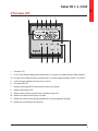 5
5
-
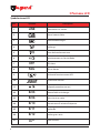 6
6
-
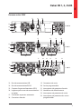 7
7
-
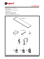 8
8
-
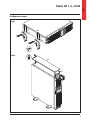 9
9
-
 10
10
-
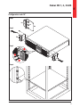 11
11
-
 12
12
-
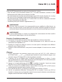 13
13
-
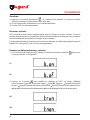 14
14
-
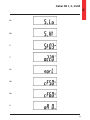 15
15
-
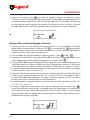 16
16
-
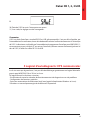 17
17
-
 18
18
-
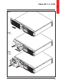 19
19
-
 20
20
-
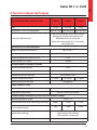 21
21
-
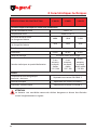 22
22
-
 23
23
-
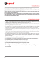 24
24
-
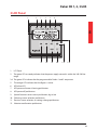 25
25
-
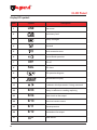 26
26
-
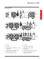 27
27
-
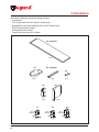 28
28
-
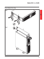 29
29
-
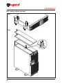 30
30
-
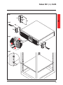 31
31
-
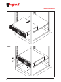 32
32
-
 33
33
-
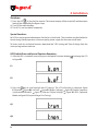 34
34
-
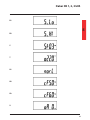 35
35
-
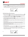 36
36
-
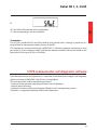 37
37
-
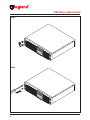 38
38
-
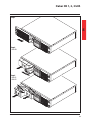 39
39
-
 40
40
-
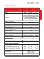 41
41
-
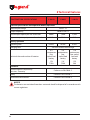 42
42
-
 43
43
-
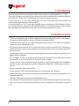 44
44
-
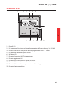 45
45
-
 46
46
-
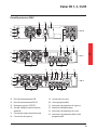 47
47
-
 48
48
-
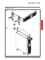 49
49
-
 50
50
-
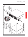 51
51
-
 52
52
-
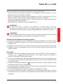 53
53
-
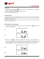 54
54
-
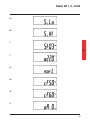 55
55
-
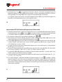 56
56
-
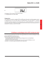 57
57
-
 58
58
-
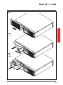 59
59
-
 60
60
-
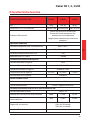 61
61
-
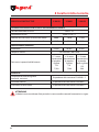 62
62
-
 63
63
-
 64
64
-
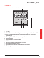 65
65
-
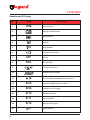 66
66
-
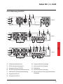 67
67
-
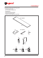 68
68
-
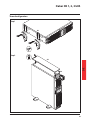 69
69
-
 70
70
-
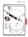 71
71
-
 72
72
-
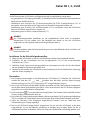 73
73
-
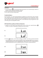 74
74
-
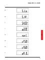 75
75
-
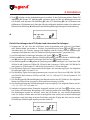 76
76
-
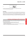 77
77
-
 78
78
-
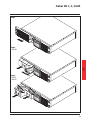 79
79
-
 80
80
-
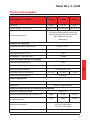 81
81
-
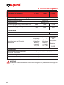 82
82
-
 83
83
-
 84
84
-
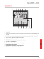 85
85
-
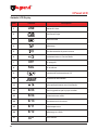 86
86
-
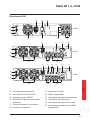 87
87
-
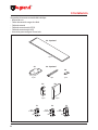 88
88
-
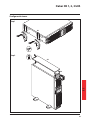 89
89
-
 90
90
-
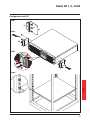 91
91
-
 92
92
-
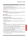 93
93
-
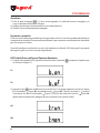 94
94
-
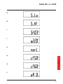 95
95
-
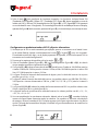 96
96
-
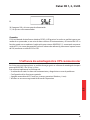 97
97
-
 98
98
-
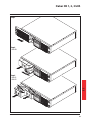 99
99
-
 100
100
-
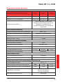 101
101
-
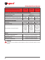 102
102
-
 103
103
-
 104
104
-
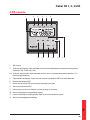 105
105
-
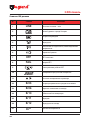 106
106
-
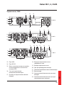 107
107
-
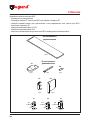 108
108
-
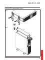 109
109
-
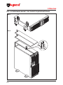 110
110
-
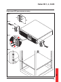 111
111
-
 112
112
-
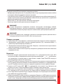 113
113
-
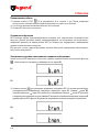 114
114
-
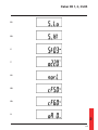 115
115
-
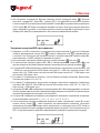 116
116
-
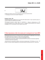 117
117
-
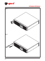 118
118
-
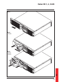 119
119
-
 120
120
-
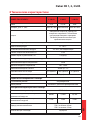 121
121
-
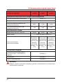 122
122
-
 123
123
-
 124
124


Legrand Daker DK 1 kVA Guía de instalación
- Tipo
- Guía de instalación
- Este manual también es adecuado para
en otros idiomas
Artículos relacionados
Otros documentos
-
 Best Power Unity/I UT3K Manual de usuario
-
Tecnoware UPS ERA LCD 2.0 Especificación
-
Tripp Lite SmartOnline Single-Phase 5kVA–6kVA Intelligent True On-Line UPS Systems El manual del propietario
-
-
ABB PowerValue 11 RT Quick Manual
-
-
-
ABB PowerValue 11 RT G2 6-10 kVA Instrucciones de operación
-
-
Tripp Lite SUPDMB20KIEC Manual de usuario
