Sanus VMPL3 Guía de instalación
- Categoría
- Soportes de pared para panel plano
- Tipo
- Guía de instalación

THANK YOU FOR CHOOSING SANUS
THE #1 TV MOUNT BRAND IN THE US.
VMPL3B
Instruction Manual

2
VMPL3B
Lo haremos sin estrés
Si tiene preguntas mientras realiza la instalación, llámenos.
1-800-359-5520 Estamos listos para ayudarlo.
We’ll Make It Stress-Free
If you have any questions along the way, just give us a call.
1-800-359-5520 We’re ready to help!

3
2.95
75.00
MIN VESA
17.00
431.8
28.88
733.7
25.20
640.00
MAX VESA COLLAPSED
2.95
75.00
MIN VESA
17.13
435.00
MIN VESA EXPANDED
44.24
1123.7
40.55
1030.00
MAX VESA
15.75
400.00
MAX VESA
27.00
685.8
0.90
22.9
0.33
8.4
0.33
8.4
16.00
406.4
24.00
609.6
42.30
1074.4
9.02
229.1
5.00
127.00
3.75
95.3
6.00
152.4
3.00
76.2
16.00
406.4
16.00
406.4
12deg
DOWN
6deg
UP
2.50
63.5
17.00
431.8
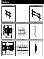
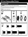
3-D - COLLAPSED VIEW
FULLY ASSEMBLED MOUNT - COLLAPSED
WALL PLATE - COLLAPSED
3-D - EXPANDED VIEW
SIDE VIEW
SIDE VIEW - TILT
WALL PLATE - EXPANDED
FULLY ASSEMBLED MOUNT - EXPANDED
Dimensions

4
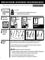
IMPORTANT SAFETY INSTRUCTIONS – SAVE THESE INSTRUCTIONS – PLEASE READ ENTIRE MANUAL PRIOR TO USE
Before getting started, let’s make sure this mount is perfect for you!
Para Español ver página 25
No
—
Perfect!
Yes
—
This mount is NOT compatible. Visit MountFinder.Sanus.com or call
1-800-359-5520 to find a compatible mount.
Please read through these instructions completely to be sure you’re comfortable with this easy install process.
Also check your TV owner’s manual to see if there are any special requirements for mounting your TV.
If you do not understand these instructions or have doubts about the safety of the installation, assembly or use
of this product, contact Customer Service at 1-800-359-5520
Do you have
all the tools
needed?
1
2
3
4
What is your
wall made of?
280 lbs.
(127 kg)
Ready to
begin?
Does your TV weigh
(including accessories)
more than 280 lbs.
(127 kg)?
CAUTION:
DO NOT install
into drywall alone
Unsure?
Drywall with
wood studs?
Solid concrete or
concrete block?
Call Customer Service:
1-800-359-5520
Perfect! Perfect!
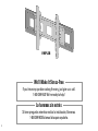
Wood Stud Install
Concrete Install
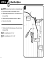
Pencil
Screwdriver
Tape
Measure
7/32 in.
(5.5 mm)
Wood
Drill Bit
Electric Drill
Hammer
1/2 in.
(13 mm)
Socket
Wrench
Drill Bit
3/8 in.
(10 mm)
Concrete
CAUTION: Avoid potential personal injuries and property damage!
● This product is designed for use in wood stud, solid concrete, and concrete block walls - DO NOT install into drywall alone
● The wall must be capable of supporting five times the weight of the TV and mount combined
● Do not use this product for any purpose not explicitly specified by manufacturer
● Manufacturer is not responsible for damage or injury caused by incorrect assembly or use
Stud
Finder
Awl

5
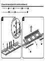
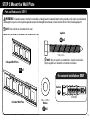
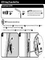
STEP 1 Select TV Hardware and Mount TV Brackets
2.5mm spacer
SPACER CUSTOM BLACK
M4X35
M5X35
M6X35
M8x25
M8X35
M8x50
M4/M5 Washer
M6/M8 Washer
THUMBSCREW 1024X03NP05
2.5 mm
22 mm
5.0 mm
M6 x 35mm
M8 x 16mm
M8 x 25mm
M8 x 35mm
M8 x 50mm
M6 x 20mm
M6 x 12mm
5/16 in. x .075 in.
5⁄16 x 2 ¾ in.
UX10x60R
For concrete installations ONLY
3/16 in.
1/4 - 20 x 7/8 in.
NOTE: Not all hardware included will be used.
WARNING: This product contains small items that could be a choking hazard if swallowed.
Before starting assembly, verify all parts are included and undamaged. If any parts are missing or damaged, do not return the damaged
item to Amazon; contact Customer Service. Never use damaged parts!
Parts and Hardware for STEP 1
04 x4
02 x4
03
01 x2
TV Bracket
TV Screws
TV Washers
Spacers
x4x8
x4

6
M6 M8
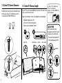
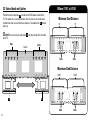
1.1 Select TV Screw Diameter
1.2 Select TV Screw Length
Hand thread screws into the threaded inserts
on the back of your TV to determine which
screw diameter (M6 or M8) to use.
FLAT BACK ROUND BACK CABLES INSET HOLES
If your TV has a flat back AND you want your TV closer to the
wall, use the shorter screws.
Spacers and longer screws are supplied to accommodate:
● Round/irregular back TVs
● TVs with inset mounting holes
● Extra space needed for cables
Too Short
Too Long
CAUTION:
Verify adequate thread
engagement with the screw or
screw/spacer combination.
- Too short will not hold the TV.
- Too long will damage the TV.
Correct
If your TV included inset
spacers or wall mount
adapters, use them UNDER the
mount hardware.
a
b

7
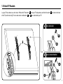
1.3 Attach TV Brackets
01
a
Lay your TV face-down on a soft surface. Position the TV brackets over your TV hole pattern, confirm the brackets are level on the back
of the TV, and install using TV screw and washer combination or you selected for your TV.
01
b
002812.eps
VMPL3 Tilting brackets at monitor
01
002815.eps
VMPL3 Tilting/Lowprole brackets curved
002812.eps
VMPL3 Tilting brackets at monitor
a
Screw and washer
b
Spacer, screw and washer
02
03
04
02
04
002812.eps
VMPL3 Tilting brackets at monitor

8
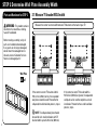
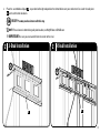
STEP 2 Determine Wall Plate Assembly Width
WARNING: This product contains
small items that could be a choking
hazard if swallowed.
Before starting assembly, verify all
parts are included and undamaged.
If any parts are missing or damaged,
do not return the damaged item to
Amazon; contact Customer Service.
Never use damaged parts!
05 x1
Wall Plate
.695 x .350 x.075 in.
3/16 in.
1/4 - 20 x 7/8 in.
5⁄16 x 2 3⁄4 in.
UX10x60R
M6/M8
M6 x 35mm
M8 x 16mm
M8 x 25mm
M8 x 35mm
M8 x 50mm
M6 x 20mm
M6 x 12mm
2.5mm
22mm
5mm
For concrete installations ONLY
Parts and Hardware for STEP 2
If the center to center TV bracket width is
9.45 inches (240mm) or greater, the expanded
wall plate can be used to complete a 3-stud
installation. Proceed to the 3-stud installation
process, step 3.
If the center to center TV bracket width is
9.41 inches (239mm) or less, the expanded
wall plate cannot be used. Proceed to the
collapsed/2-stud installation process, step 3.
NOTE: The collapsed wall plate should
be used for all 2-stud installations with TV
bracket widths up to 25.20 inches (640 mm).
Measure the center to center width between TV brackets on the back of your TV.
2.1 Measure TV bracket VESA width

9
STEP 2 Determine Wall Plate Assembly Width
05
1
2.2 Loosen the front wall plate (for 3-stud/slot installation only)
1. Remove the nuts
N
and washers
W
from the threaded studs
A
of the wall plate
05
.
2. Lift the center plate
C
of the wall plate
05
up and away from the back wall plates
B
.
N
W
A
2
B
C
B

10
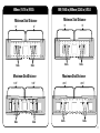
2.3 Extend back wall plates
Extend the back wall plates
B
based on the VESA pattern width of the
TV. This allows for a 3-stud installation. Use the slots on the center plate
to determine how far to extend the wall plates. Threaded studs
A
should
point up.
NOTE: Be sure the back wall plates
B
do not protrude from the sides
of the TV.
300mm (11.81 in) VESA
Center
Slots
34567 76543
Slots
Maximum Stud Distance
16.65” 16.65”
Slots
4
6
Slots
5 3
16” 16”
Slots
5 3
Slots
3
5
Minimum Stud Distance
B B

11
400mm (15.74 in) VESA
500 (19.68 in)/600mm (23.62 in) VESA
16” 16”
Slots
5 3
Slots
3
5
Minimum Stud Distance
16” 16”
Slots
5 3
Slots
3
5
Minimum Stud Distance
Maximum Stud Distance
18.45” 18.45”
Slots
5
7
Slots
6 4
Maximum Stud Distance
20.25”
20.25”
Slots
5
7
Slots
7 5

12
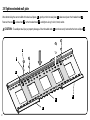
2.4 Tighten extended wall plate
After determining the correct width of the back wall plates
B
, gently set the front wall plate
C
down evenly over the threaded studs
A
.
Reattach the nuts
N
and washers
W
to the threaded studs
A
and tighten using 1/2 inch (13mm) socket.
CAUTION: To avoid personal injury or property damage, all four threaded studs
A
must be securely fastened to the front wall plate
C
.
C
B
N
W
A
B

13
STEP 3 Mount the Wall Plate
2.5mm spacer
SPACER CUSTOM BLACK
M4X35
M5X35
M6X35
M8x25
M8X35
M8x50
M4/M5 Washer
M6/M8 Washer
THUMBSCREW 1024X03NP05
2.5 mm
22 mm
5.0 mm
M6 x 35mm
M8 x 16mm
M8 x 25mm
M8 x 35mm
M8 x 50mm
M6 x 20mm
M6 x 12mm
5/16 in. x .075 in.
5⁄16 x 2 ¾ in.
UX10x60R
For concrete installations ONLY
3/16 in.
1/4 - 20 x 7/8 in.
Parts and Hardware for STEP 3
WARNING: This product contains small items that could be a choking hazard if swallowed. Before starting assembly, verify all parts are included and
undamaged. If any parts are missing or damaged, do not return the damaged item to Amazon; contact Customer Service. Never use damaged parts!
NOTE: Not all hardware included will be used.
05 x1
Collapsed Wall Plate
Washer
Anchors
.695 x .350 x.075 in.
3/16 in.
1/4 - 20 x 7/8 in.
5⁄16 x 2 3⁄4 in.
UX10x60R
M6/M8
M6 x 35mm
M8 x 16mm
M8 x 25mm
M8 x 35mm
M8 x 50mm
M6 x 20mm
M6 x 12mm
2.5mm
22mm
5mm
For concrete installations ONLY
Extended Wall Plate
NOTE: Only 4x lag bolts are needed for 2-stud/slot installations;
Only 6x lag bolts are needed for 3-stud/slot installations.
Lagbolts
06 x6
07 x6
08

14
CAUTION: Avoid potential personal injuries and property damage!
● Drywall covering the wall must not exceed 5/8 in. (16 mm)
● Minimum wood stud size: nominal 2 x 4 in. (51 x 102 mm) actual 1½ x
3½ in. (38 x 89 mm)
● Minimum horizontal space between fasteners: 16 in. (406mm)
● Stud center must be verified
1
Min. 3 1/2 in.
(89 mm)
Min. 1 1/2 in.
(38 mm)
STEP 3A Wood Stud Option
1. Verify the center of the stud(s) using an awl, a thin nail, or an edge
to edge stud finder.
NOTE: 2-stud width options = 16" to 24"
NOTE: 3-stud width options = 16" to 20.25"
Min. 16 in.
(406mm)
Max. 5/8 in.
(16 mm)

15
2. Place the assembled wall plate
05
at your desired height and position the slotted holes over your stud center line. Level the wall plate
05
and mark the hole locations.
NOTE: For assistance in determining wall plate location, see HeightFinder at SANUS.com.
IMPORTANT: Be sure you mark and drill into the center of the stud.
05
2
2-Stud Installation
2
3-Stud Installation
05
HEAVY! You may need assistance with this step.
4X
6X

16
3. Drill pilot holes using a 7/32 in. (5.5 mm) diameter drill bit.
IMPORTANT: Pilot holes must be drilled to a depth of 2 ¾ in. (70 mm).
NOTE: Drilling into 2 studs is only available for 16” to 24” stud spacing.
NOTE: Drilling into 3 studs is only available for 16” to 20.25” stud spacing.
3
2-Stud Installation
3
3-Stud Installation
2 ¾ in. (70 mm)
7/32 in. (5.5
mm)
4X
6X

17
4. Install and tighten lag bolts
06
only until the washers
07
are pulled firmly against the wall plate
05
.
CAUTION: Improper use could reduce the holding power of the lag bolt. To avoid potential injuries or property damage, DO NOT over-
tighten the lag bolts
06
.
05
4
2-Stud Installation
4
3-Stud Installation
05
06
07
06
07
4X
6X

18
CAUTION: Avoid potential personal injuries and property damage!
● Mount the collapsed wall plate
05
directly onto the concrete surface
● Minimum solid concrete thickness: 8 in. (203 mm)
● Minimum concrete block size: 8 x 8 x 16 in. (203 x 203 x 406 mm)
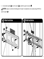
1. Position the collapsed wall plate
05
on the wall at your desired height. Level the wall plate
05
and mark the hole locations.
NOTE: For assistance in determining wall plate location, see Height Finder at sanus.com.
NOTE: 24 in. installation spacing shown.
05
STEP 3B Solid Concrete or Concrete Block Option
1

19
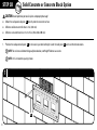
Solid Concrete or Concrete Block Option
2. Drill pilot holes using a 3/8 in. (10 mm) diameter drill bit.
IMPORTANT: Pilot holes must be drilled to a depth of 2 ¾ in. (70 mm). Never drill into the mortar between blocks.
3. Insert lag bolt anchors
08
.
NOTE: Be sure the anchors
08
are seated flush with the concrete surface.
2
3/8 in.
(10 mm)
3 in. (75 mm)
002862.eps
3
08

20
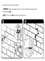
05
4
07
06
06
4. Insert lag bolts
06
through the washer
07
, wall plate
05
, and into the anchors
08
.
CAUTION: Improper use could reduce the holding power of the lag bolt. To avoid potential injuries or property damage:
● Tighten the lag bolts
06
only until the washers
07
are pulled firmly against the wall plate
05
.
● DO NOT over-tighten the lag bolts
06
.
07

21
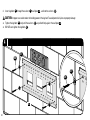
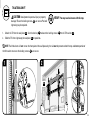
STEP 4 Hang TV onto Wall Plate
HEAVY! You may need assistance with this step.
CAUTION: Avoid potential personal injury or
property damage! Ensure the locking screws
09
are
secure. Periodic tightening may be required.
2.5mm spacer
SPACER CUSTOM BLACK
M4X35
M5X35
M6X35
M8x25
M8X35
M8x50
M4/M5 Washer
M6/M8 Washer
THUMBSCREW 1024X03NP05
2.5 mm
22 mm
5.0 mm
M6 x 35mm
M8 x 16mm
M8 x 25mm
M8 x 35mm
M8 x 50mm
M6 x 20mm
M6 x 12mm
5/16 in. x .075 in.
5⁄16 x 2 ¾ in.
UX10x60R
For concrete installations ONLY
3/16 in.
1/4 - 20 x 7/8 in.
Parts and Hardware for STEP 4
09 x2
Locking Screw
10 x1
Hex Key
1. Hang the TV onto the wall plate
05
by first hooking the top of the bracket
01
, then pressing the bottom of the TV bracket
01
into the
wall plate
05
until the locking slot is underneath the wall plate
05
.
2. To lock the TV in place, use the hex key to tighten the locking screws
on the TV brackets
01
.
10
09
09
01
05
01
10
1 2
2.5mm spacer
SPACER CUSTOM BLACK
M4X35
M5X35
M6X35
M8x25
M8X35
M8x50
M4/M5 Washer
M6/M8 Washer
THUMBSCREW 1024X03NP05
2.5 mm
22 mm
5.0 mm
M6 x 35mm
M8 x 16mm
M8 x 25mm
M8 x 35mm
M8 x 50mm
M6 x 20mm
M6 x 12mm
5/16 in. x .075 in.
5⁄16 x 2 ¾ in.
UX10x60R
For concrete installations ONLY
3/16 in.
1/4 - 20 x 7/8 in.

22
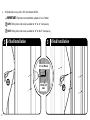
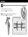
TILT
Your TV should adjust easily when moved, then stay in place.
Adjust the tilt tension knob
T
if your TV naturally tilts up or down.
NOTE: If you do not intend to adjust the tilt for different viewing locations, you can
tighten the tilt tension knobs
T
to prevent unwanted movement.
T
Adjustments

23
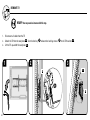
1. Unlock the TV from the wall plate
05
: Use the hex key
10
to loosen the locking screws
09
on the TV brackets
01
.
2. Slide the TV left or right along the wall plate
05
to reposition.
TV LATERAL SHIFT
NOTE: The tilt brackets will not rest on the front plate of the wall plate only; the rail must be present on both the top and bottom portion of
the tilt brackets to ensure the locking screws
09
are secure.
HEAVY! You may need assistance with this step.
09
05
1 2
05
Adjustments
CAUTION: Avoid potential personal injury or property
damage! Ensure the locking screws
09
are secure. Periodic
tightening may be required.

24
REMOVE TV
HEAVY! You may need assistance with this step.
09
01
05
05
32
1. Disconnect all cables from the TV.
2. Unlock the TV from the wall plate
05
: Use the hex key
10
to loosen the locking screws
09
on the TV brackets
01
.
3. Lift the TV up and off the wall plate
05
.
1

25
Antes de comenzar, verifiquemos que este soporte sea el ideal para sus necesidades.
INSTRUCCIONES DE SEGURIDAD IMPORTANTES. CONSÉRVELAS. LEA TODO EL MANUAL ANTES DE UTILIZAR ESTE PRODUCTO.
ESPAÑOL
No
—
¡Perfecto!
Sí
—
Este soporte NO es compatible. Visite MountFinder.Sanus.com o llame al
1-800-359-5520 para encontrar un soporte compatible.
¿Su televisor pesa
más de 127 kg
(280 lb), incluidos
los accesorios?
Lea estas instrucciones en su totalidad para estar seguro de sentirse cómodo con este fácil proceso de instalación. Consulte
también el manual del usuario de su televisor para ver si existe algún requisito especial para instalar su televisor en la pared.
Si no entiende las instrucciones o si tiene dudas acerca de la seguridad de la instalación, del ensamblado o del uso del
producto, póngase en contacto con el servicio de atención al cliente al 1-800-359-5520.
¿Tiene
todas las
herramientas
necesarias?
1
2
3
4
¿De qué está
hecha su pared?
¿No está
seguro?
¿Hormigón sólido
o bloques de
cemento?
127 kg
(280 lb)
¿Listo para
comenzar?
13 mm
(1/2”)
¿Tabiques
de yeso con
montantes de
madera?
Llame al
1-800-359-5520
¡Perfecto! ¡Perfecto!
Destornillador
Cinta
métrica
Broca
Broca
Taladro
eléctrico
Martillo
Llave de tubo
PRECAUCIÓN: Evite posibles lesiones personales y daños materiales.
● Este producto incluye instrucciones y elementos de sujeción para su instalación en paredes con montantes de madera,
en superficies de hormigón y sobre bloques de cemento. NO lo instale en tabiques únicamente de yeso.
● La pared debe soportar cinco veces el peso del televisor y del soporte juntos.
● No utilice este producto para ningún otro propósito que no sea el explícitamente especificado por el fabricante.
● El fabricante no se responsabiliza por ningún daño o lesión resultante del montaje incorrecto o de uso indebido.
5,5 mm
(7/32'')
Madera
10 mm
(3/8'')
Hormigón
Concrete Install
Lápiz
PRECAUCIÓN:
NO lo instale en
tabiques únicamente
de yeso
Punzón
Localizador
de montantes
Wood Stud Install

26
ADVERTENCIA: Este producto contiene piezas pequeñas que, si fuesen tragadas, podrían producir asfixia.
Antes de iniciar el ensamblaje, compruebe que todas las piezas estén incluidas y en buenas condiciones. Si faltan piezas o alguna está dañada,
no devuelva el artículo al Amazon; póngase en contacto con el servicio de atención al cliente. Nunca utilice piezas deterioradas.
ESPAÑOL
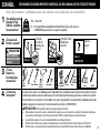
Piezas y elementos de sujeción para el PASO 1
PASO 1
Seleccionar los elementos de sujeción e instalar las placas de
sujeción del televisor
Ver página 5
NOTA: No todos los accesorios incluidos deberán utilizarse.
1,1 Seleccionar los tornillos del televisor
Enrosque manualmente los tornillos en los encastres roscados del dorso del televisor a fin de determinar qué diámetro de tornillos
(M6 o M8) utilizar.
Los separadores y tornillos se proporcionan para instalar la placa de sujeción de su televisor.
Determine cuál es su preferencia para la configuración de los separadores al fijar la placa de sujeción de su televisor.
Instale los separadores
04
debajo de la placa de sujeción del televisor para crear más espacio para los televisores con forma irregular en la
parte posterior o cables extensos.
PRECAUCIÓN: Verifique que la combinación de tornillo y separador enrosque correctamente en su televisor. Si el tornillo es demasiado
corto, el televisor no se sostendrá; si es demasiado largo, dañará el televisor.
1,2 Seleccionar longitud de tornillo de TV
1,3 Fije las placas de montaje al televisor
Posicione el módulo de la placa
01
de sujeción sobre el patrón de orificios del televisor, céntrelo horizontalmente y coloque sin ajustar la
combinación de separador, tornillo y arandela
a
o
b
que seleccionó para su televisor.

27
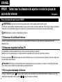
2,1 Medir el ancho VESA del soporte de TV
2,2 Afloje la placa de pared frontal (solo para instalación de 3 montantes/ranuras)
Mida el ancho de centro a centro entre los soportes de TV de la parte trasera de su TV.
Si el ancho de centro a centro del soporte de TV es de 9,41pulgadas (239mm) o menos, no se puede utilizar la placa de pared extendida.
Proceda con la instalación contraída/de 2 montantes, paso 3.
NOTA: la placa de pared contraída debería utilizarse para todas las instalaciones de 2 montantes con soportes de TV de hasta
25,20pulgadas (640mm) de ancho.
Si el ancho de centro a centro del soporte de TV es de 9,45pulgadas (240mm) o más, se puede utilizar la placa de pared extendida para
completar una instalación de 3montantes. Proceda con la instalación de 3 montantes, paso 3.
ESPAÑOL
PASO 2 Determinar el ancho del ensamblaje de la placa mural
Ver página 8
ADVERTENCIA: Este producto contiene piezas pequeñas que, si fuesen tragadas, podrían producir asfixia.
Antes de iniciar el ensamblaje, compruebe que todas las piezas estén incluidas y en buenas condiciones. Si faltan piezas o alguna está dañada,
no devuelva el artículo al Amazon; póngase en contacto con el servicio de atención al cliente. Nunca utilice piezas deterioradas.
1. Coloque su televisor boca abajo sobre una superficie blanda. Retire las tuercas
N
y las arandelas
W
de los pernos roscados
A
de la
placa mural
05
.
2. Levante la placa central
C
de la placa mural
05
hacia arriba y retírela de las placas traseras
B
.
2,3 Extienda las placas de pared traseras
Extienda las placas de pared traseras
B
basadas en el ancho del patrón VESA del TV. Esto permite una instalación de 3 montantes. Use las
ranuras de la placa central para calcular cuánto debe extender las placas de pared. Los pernos roscados
A
deben sobresalir.
NOTA: asegúrese de que las placas de pared traseras
B
no sobresalen por los lados del TV.
Piezas y elementos de sujeción para el PASO 2

28
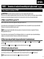
Piezas y elementos de sujeción para el PASO 3
NOTA: No todos los accesorios incluidos deberán utilizarse.
SOLO para instalaciones en hormigón
PRECAUCIÓN: No usar en placas de yeso o montantes de madera
UX10 x 60R
08
PASO 3
Fijar el módulo del brazo o la placa mural a la pared
Ver página 13
PRECAUCIÓN: Evite lesiones y daños materiales.
● El yeso que recubre la pared no debe exceder los 16 mm (5/8").
● Tamaño mínimo del montante de madera: común 51 mm x 102 mm (2" x 4") (nominal 38 mm x 89 mm /1½" x 3½").
● Espacio horizontal mínimo entre los elementos de sujeción: 406 mm (16").
● Se debe verificar la parte central.
Ver página 14
ADVERTENCIA: Este producto contiene piezas pequeñas que, si fuesen tragadas, podrían producir asfixia.
Antes de iniciar el ensamblaje, compruebe que todas las piezas estén incluidas y en buenas condiciones. Si faltan piezas o alguna está dañada,
no devuelva el artículo al Amazon; póngase en contacto con el servicio de atención al cliente. Nunca utilice piezas deterioradas.
2,4 Apriete la placa de pared extendida
Tras fijar la anchura correcta de las placas de pared traseras
B
, haga descender poco a poco la placa de pared frontal
C
de manera
uniforme sobre los pernos roscados
A
. Vuelva a fijar las tuercas
N
y las arandelas
W
a los pernos roscados
A
y apriételos con una llave
de 1/2pulgada (13mm).
ESPAÑOL
PRECAUCIÓN: Para evitar lesiones personales o daños materiales, los cuatro pernos roscados
A
deben fijarse firmemente a la placa de
pared frontal
C
.
PASO 3A
Opción para montantes de madera
NOTA: para la instalación de 2 montantes/ranuras solo se necesitan 4x pernos tirafondo; para la instalación de 3 montantes/ranuras solo se
necesitan 6x pernos tirafondo.

29
ESPAÑOL
2. Coloque la placa de pared ensamblada
05
a la altura deseada y coloque los agujeros ranurados sobre la línea central de su perno. Nivele
la placa de pared
05
y marque las ubicaciones de los agujeros.
4. Ajuste los tornillos tirafondo
06
solamente hasta que las arandelas
07
queden firmes contra la placa mural
05
.
PRECAUCIÓN: El uso indebido podría reducir la capacidad de retención de los tornillos tirafondo. Para evitar lesiones y daños materiales.
NO ajuste en exceso los tornillos tirafondo
06
.
1. Verifique el centro de los montantes con un punzón o un clavo delgado, o bien utilice un detector de bordes de montantes.
NOTA: opciones de ancho de 2 montantes = 16pulg. a 24pulg.
NOTA: opciones de ancho de 3 montantes = 16pulg. a 20,25pulg.
¡ELEMENTO PESADO! Es posible que necesite ayuda en este paso.
NOTA: Si necesita ayuda para determinar la ubicación de la placa mural, utilice la herramienta HeightFinder disponible en SANUS.com.
IMPORTANTE: Asegúrese de marcar y perforar el centro del montante.
3. Haga los dos orificios guía con una mecha de 5,5 mm (7/32”) de diámetro.
IMPORTANTE: Los orificios guía deben realizarse hasta una profundidad de 70 mm (2 ¾”).
NOTA: taladrar 2 montantes solo está disponible para anchuras de 16pulg. a 24pulg.
NOTA: taladrar 3 montantes solo está disponible para anchuras de 16pulg. a 20,25pulg.
PRECAUCIÓN: Evite lesiones y daños materiales.
• Monte la placa de pared
05
contraída directamente sobre la superficie de hormigón
• Espesor mínimo del hormigón: 203 mm (8")
• Tamaño mínimo del bloque de cemento: 203 x 203 x 406 mm (8" x 8" x 16")
PASO 3B
Opción para hormigón sólido o bloques de cemento
Ver página 18

30
PASO 4
Colgar el televisor en la placa mural
Ver página 21
ESPAÑOL
1. Coloque la placa mural
05
en la pared a la altura que desee. Nivele la placa mural y marque la ubicación de los orificios.
NOTA: Si necesita ayuda para determinar la ubicación de la placa mural, utilice la herramienta HeightFinder disponible en SANUS.com.
NOTA: Se muestra la instalación de 24pulg.
2. Haga los dos orificios guía con una mecha de 10 mm (3/8") de diámetro.
IMPORTANTE: Los orificios guía deben realizarse hasta una profundidad de 70 mm (2 ¾"). Nunca perfore el cemento que une los bloques.
3. Inserte los anclajes
08
para tornillos tirafondo .
NOTA: Asegúrese de que los anclajes
08
estén alineados con la superficie de concreto.
4. Inserte los anclajes para tornillos tirafondo
06
. Luego, pase los tornillos tirafondo
06
por las arandelas
07
y la placa mural
05
e insértelos en los anclajes
08
.
1. Acople el TV a la placa de pared
05
enganchando primero la parte superior del soporte de TV
01
, y luego empujando la parte nferior del
soporte de TV
01
contra la placa de pared
05
hasta que la ranura de bloqueo esté bajo la placa de pared
05
.
2. Para fijar el TV, use la llave hexagonal
10
y apriete los tornillos de bloqueo
09
del soporte de TV
01
.
PRECAUCIÓN: Evite lesiones y daños materiales. Verifique que los tornillos de seguridad
09
estén firmes. Puede ser necesario ajustar los tornillos
periódicamente.
INCLINACIÓN:
DESPLAZADOR LATERAL DEL TELEVISOR
El televisor debe acomodarse fácilmente al moverlo y luego quedar en su lugar. Si su televisor se inclina naturalmente hacia arriba o hacia
abajo, ajuste la perilla de tensión de inclinación
T
.
NOTA: los soportes reclinables no estarán apoyados solo en la placa frontal de la placa de pared; los rieles deben estar tanto en la parte
superior como en la inferior de los soportes reclinables para que los tornillos de bloqueo
09
queden fijos.
EXTRACCIÓN DEL TELEVISOR
PRECAUCIÓN: Evite lesiones y daños materiales. Verifique que los tornillos de seguridad
09
estén firmes. Puede ser necesario ajustar los tornillos
periódicamente.
Ajustes
Ver página 22

31
Legrand AV Inc. and its aliated corporations and subsidiaries (collectively, “Legrand), intend to make this manual accurate and complete. However, Legrand makes
no claim that the information contained herein covers all details, conditions, or variations. Nor does it provide for every possible contingency in connection with
the installation or use of this product. The information contained in this document is subject to change without notice or obligation of any kind. Legrand makes no
representation of warranty, expressed or implied, regarding the information contained herein. Legrand assumes no responsibility for accuracy, completeness or
suciency of the information contained in this document.
Legrand AV Inc. y sus empresas asociadas y filiales (colectivamente “Legrand”) tienen la intención de que este manual sea preciso y completo. Sin embargo, Legrand no garantiza
que la información que contiene incluya todos los detalles condiciones y variaciones, ni que contemple toda posible contingencia en conexión con la instalación y uso de este
producto. La información contenida en este documento es susceptible de ser modificada sin aviso ni obligación de ningún tipo. Legrand no hace ninguna manifestación de garantía,
explícita o implícita, respecto a la información contenida este documento. Legrand no asume ninguna responsabilidad por la exactitud, integridad o suficiencia de la información
contenida en este documento.

32
1
2
3
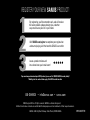
REGISTER YOUR NEW
SANUS
PRODUCT!
If you ever have questions about your SANUS product, give us a call at 1-800-359-5520. We're ready to help!
‘Monthly prize’ rules and restrictions apply. Visit SANUS.com for more info.
By registering, you'll be entered to win, and will receive
the latest product updates, design tips, and other
ways to enhance your life in your home.
Visit SANUS.com/register to complete your registration
and start enjoying all of the benefits SANUS has to oer.
Leave a product review and
let us know how your install went!
©2020 Legrand AV Inc. All rights reserved. SANUS is a division of Legrand.
All other brand names or marks are used for identification purposes and are trademarks of their respective owners.
SANUS • 6436 City West Parkway • Eden Prairie, MN 55344 USA
1
2
3
If you ever have questions about your SANUS product, give us a call at 1-800-359-5520. We're ready to help!
‘Monthly prize’ rules and restrictions apply. Visit SANUS.com for more info.
By registering, you'll be entered to win, and will receive
the latest product updates, design tips, and other
ways to enhance your life in your home.
Visit SANUS.com/register to complete your registration
and start enjoying all of the benefits SANUS has to oer.
Leave a product review and
let us know how your install went!
6901-602497 00
-
 1
1
-
 2
2
-
 3
3
-
 4
4
-
 5
5
-
 6
6
-
 7
7
-
 8
8
-
 9
9
-
 10
10
-
 11
11
-
 12
12
-
 13
13
-
 14
14
-
 15
15
-
 16
16
-
 17
17
-
 18
18
-
 19
19
-
 20
20
-
 21
21
-
 22
22
-
 23
23
-
 24
24
-
 25
25
-
 26
26
-
 27
27
-
 28
28
-
 29
29
-
 30
30
-
 31
31
-
 32
32


Sanus VMPL3 Guía de instalación
- Categoría
- Soportes de pared para panel plano
- Tipo
- Guía de instalación
en otros idiomas
- English: Sanus VMPL3 Installation guide
Artículos relacionados
-
Sanus CCSTVK Guía de instalación
-
Sanus SA-IWCM2 Manual de usuario
-
-
-
-
-
-
-
-


