Craftsman 139.53989 El manual del propietario
- Categoría
- Abridor de puerta de garage
- Tipo
- El manual del propietario
Este manual también es adecuado para

Owner's Manual/Manual Del Propietario
CRRFTSMI:I
1/2 HP
GARAGE DOOR OPENER
ABRIDOR DE PUERTA DE COCHERA
For Residential Use Only/Solo para uso residencial
Model/Modelo139.53989
m
Z
G3
m
"0
Z_
O
Read and follow all safety rules
and operating instructions before
first use of this product.
Fasten the manual near the garage
door after installation.
Periodic checks of the opener are
required to ensure safe operation.
Leer y seguir todas las reglas de
seguridad y las instrucciones de
operacion antes de usar este
producto por primera vez.
Guardar este manual cerca de la
puerta de la cochera.
Se deben realizar revisiones
periodicas del abridor de puertas
para asegurar su operacion
segura.
Sears, Roebuck and Co., Hoffman Estates, IL 60179 U.S.A
www.sears.com/craftsman

TABLE OF CONTENTS
Introduction 2.7
Safety symbol and signal word review ........................ 2
Preparing your garage door ........................................ 3
Tools needed ............................................................... 3
Planning .................................................................. 4-5
Carton inventory .......................................................... 6
Hardware inventory ..................................................... 7
Assembly 8.11
Assemble the rail and install trolley ............................. 8
Fasten rail to motor unit and install idler pulley .......... 9
Install the chain/cable ................................................ 10
Tighten the chain ....................................................... 11
Installation 11.2 7
Installation safety instructions .................................... 11
Determine the header bracket location ................ 12-13
Install the header bracket .......................................... 14
Attach the rail to the header bracket ......................... 15
Position the opener ................................................... 16
Hang the opener ....................................................... 17
Install the door control ............................................... 18
Install the lights ......................................................... 19
Attach the emergency release rope and handle ....... 19
Electrical requirements .............................................. 20
Install the Protector System ®................................ 21-23
Fasten the door bracket ....................................... 24-25
Connect the door arm to the trolley ..................... 26-27
Adjustment 28.30
Adjust the travel limits ............................................... 28
Adjust the force ......................................................... 29
Test the safety reversal system ................................. 30
Test the Protector System '_........................................ 30
Operation 31.34
Operation safety instructions ..................................... 31
Using your garage door opener ................................ 31
Using the wall-mounted Door Control ....................... 32
To open the door manually ........................................ 32
Care of your garage door opener .............................. 33
Having a problem? .................................................... 34
Programming 35.36
To add a hand-held remote control ........................... 35
To erase all codes ..................................................... 35
3-Function Remotes Controls ................................... 35
To add or change a Keyless Entry PIN ..................... 36
Repair Parts 37.38
Rail assembly parts ................................................... 37
Installation parts ........................................................ 37
Motor unit assembly parts ......................................... 38
Accessories 38
Warranty 39
Service Numbers 40
INTRODUCTION
Safety Symbol
and Signal Word Review
This garage door opener has been designed and tested to offer safe service provided it is installed, operated,
maintained and tested in strict accordance with the instructions and warnings contained in this manual.
Mechanical
Electrical
When you see these Safety Symbols and Signal
Words on the following pages, they will alert you to
the possibility of serious injury or death if you do
not comply with the warnings that accompany them.
The hazard may come from something mechanical
or from electric shock. Read the warnings carefully.
When you see this Signal Word on the following
pages, it will alert you to the possibility of damage to
your garage door and/or the garage door opener if
you do not comply with the cautionary statements
that accompany it. Read them carefully.

Preparing your Garage Door
Before you begin:
• Disable locks.
• Remove any ropes connected to garage door.
• Complete the following test to make sure your
garage door is balanced and is not sticking or
binding:
1. Lift the door about halfway as shown. Release
the door. If balanced, it should stay in place
supported entirely by its springs.
2. Raise and lower the door to see if there is any
binding or sticking.
If your door binds, sticks, or is out of balance, call
a trained door systems technician.
To prevent possible SERIOUSINJURYORDEATH:
• ALWAYScall atrained door systemstechnician if
garagedoor binds, sticks, or is out of balance An
unbalancedgarage door may not reversewhen
required.
• NEVERtry to loosen, move or adjust garagedoor, door
springs, cables,pulleys, brackets or their hardware,all
of which are underEXTREMEtension.
• DisableALL locks and removeALL ropes connectedto
garagedoor BEFOREinstalling and operating garage
door openerto avoid entanglement.
To prevent damageto garage door and opener:
• ALWAYSdisablelocks BEFOREinstalling and operating
the opener
• ONLYoperategarage door opener at 120V,60 Hzto
avoid malfunction and damage
Sectional Door
One-Piece Door
Level
Tools Needed
During assembly, installation and adjustment of the
opener, instructions will call for hand tools as
illustrated below.
Stepladder
Pencil
Tape Measure
Dr_ Wire Cutters
Drilt 3/16", 5/16"
and 5/32"
O_ lS_'c_;t/_"i'_I 16W'r,e9n/ih" Locking pliers
and 1/4"
Hack Saw
Screwdriver
Adjustable End Wrench

Planning
Identify the type and height of your garage door.
Survey your garage area to see if any of the
conditions below apply to your installation. Additional
materials may be required. You may find it helpful to
refer back to this page and the accompanying
illustrations as you proceed with the installation of
your opener.
Depending on your requirements, there are several
installation steps which may call for materials or
hardware not included in the carton.
• Installation Step 1 - Look at the wall or ceiling
above the garage door. The header bracket must
be securely fastened to structural supports.
• Installation Step 5 - Do you have a finished ceiling
in your garage? If so, a support bracket and
additional fastening hardware may be required.
• Installation Step 10 - Depending upon garage
construction, extension brackets or wood blocks
may be needed to install sensors.
• Installation Step 10 - Alternate floor mounting of
the safety reversing sensor will require hardware
not provided.
Do you have an access door in addition to the
garage door? If not, Model 53702 Emergency Key
Release is required. See Accessories page.
Look at the garage door where it meets the floor.
Any gap between the floor and the bottom of the
door must not exceed 1/4" (6 mm). Otherwise, the
safety reversal system may not work properly. See
Adjustment Step 3. Floor or door should be
repaired.
SECTIONAL DOOR INSTALLATIONS
• Do you have a steel, aluminum, fiberglass or glass
panel door? If so, horizontal and vertical
reinforcement is required (Installation Step 11).
• The opener should be installed above the center of
the door. If there is a torsion spring or center
bearing plate in the way of the header bracket, it
may be installed within 4 feet (1.22 m) to the left or
right of the door center. See Installation Steps 1
and 11.
• If your door is more than 7 feet high (2.13 m), see
rail extension kits listed on Accessories page.
SECTIONAL DOOR INSTALLATION
Horizontal and vertical reinforcement
is needed for lightweight garage doors
(fibergIass, steel, aluminum, door with
glass panels, etc) See page 24 for detaiIs.
Header WalI
Slack in chain tension
is normal when
garage door is closed.
Extension Spring
OR
j Torsion Spring
FINISHED CEILING
Support bracket &
fastening hardware
is required
See page 17
Rail
Gap between floor
and bottom of door
Safety Reversing Sensor must not exceed 1/4" (6 mm)
WaIF
mounted
Door
Control
Safety Reversing
Sensor
Access Door
O

Planning (continued)
ONE-PIECE DOOR INSTALLATIONS
• Generally, a one-piece door does not require
reinforcement. If your door is lightweight, refer to
the information relating to sectional doors in
Installation Step 11.
• Depending on your door's construction, you may
need additional mounting hardware for the door
bracket (Step 11).
Without a properly working safety reversal system,
persons (particularly small children) could be
SERIOUSLYINJUREDor KILLEDby a closing garage
door.
•The gap betweenthe bottom of the garagedoor and
the floor MUSTNOTexceed1/4" (6 mm). Otherwise,
the safety reversal system may not work properly.
•The floor or the garage door MUSTbe repairedto
eliminate the gap.
ONE-PIECE DOOR WITHOUT TRACK FINISHED CEILING
Support bracket
& fastening
hardware is required.
See page 17
Header Wail
Rail
Slack in chain tension
is normal when garage
door is dosed
Safety Reversing Sensor
J
Access
Door
Safety Reversing
Sensor
Gap between floor
and bottom of door must not exceed 1/4" (6 mm)
Wall-mounted
Door Control
ONE-PIECE DOOR WITH TRACK
Motor Unit
eader
/all
CLOSED POSITION
Trolley Stop Bolt Cabte Trolley
Bracket Rail
_{ Straight Curved
Door DrOOr
_ Garage Door ..... _ _
Emergency
Release
Rope & Handle
Reversing
Gap between floor Sensor
J and bottom of door
Safety must not exceed 1/4" (6 mm)
Reversing Sensor
CLOSED POSITION
Trolley Stop Bolt Cable
_. r_
Header Curved _:
Bracket DoorArrt_ / L--
_/_ Door°°°°°°_ °°°°°)J
/_ Bracket StraightDoor
/_/1_ Garage Arm
//./I Door
Chain
RaiI
Emergency
Release
-- Rope &
Handle

Carton Inventory
Your garage door opener is packaged in one carton
which contains the motor unit and the parts illustrated
below. Note that accessories will depend on the
model purchased. If anything is missing, carefully
check the packing material. Parts may be stuck in the
foam. Hardware for assembly and installation is
shown on the next page. Save the carton and
packing material until installation and adjustment
is complete.
Premium Control Console
SECURITY+ Three-Function
Remote Control with Visor Clip (2)
Trotley
Chain Spreader
Keyless Entry
Motor Unit with 2 Light Lenses
Rail
Center/Back
Sections
Chain
idler Pulley
Rail
Fron! (header) /_/#,,2
Safety Sensor
Bracket (2)
Header Bracket Door Bracket
(2) Safety Reversing Sensors
(1 Sending Eye and 1 Receiving Eye)
with 2-Conductor White & White/Black
Bell Wire attached
U Bracket
Curved Door
Arm Section
2-Conductor Bell Wire
White & White/Red
I Safety Labels
and
Literature
Hanging Brackets
Straight Door
Arm Section

Hardware Inventory
Separate all hardware and group as shown below for the assembly and installation procedures.
ASSEMBLY HARDWARE
F
© @ @
Lock Nut Lock Washer Nut
1/4"-20 (2) 3/8" (1) 3/8" (1)
Bott 1/4"-20 x 1-3/4" (2)
Trotley Threaded Shaft (1)
i
Master
Link (2)
Idler Bolt (1)
INSTALLATION HARDWARE
Carriage Bolt
1/4"-20 x 1/2" (2)
Wing Nut
1/4"-20 (2)
Lag Screw
5/16"-9 x 1-5/8" (2)
Lag Screw
5/16"-18 x 1-7/8" (2)
Carriage Bolt
5/16"-18 x 2-1/2" (2)
o]
CIevis Pin
5/16" x 1-1/2" (1)
O
Ring
Fastener (3)
IIIIIIIIII_
Hex BoIt
5/16"-18 x 7/8" (4)
©
Nut 5/16"-18 (8)
©
Lock Washer 5/16" (7)
I,J,I,I,F,F,I,I,J,I,I,I,I>
Screw
6AB x 1-1/4" (2)
Dry Walt Anchors (2)
CIevis Pin
5/16" x 1" (1)
Handle
Insulated
Staples (30)
_ IIIIIIIIIIIIIIIIIIIII
Screw 6-32 x 1" (2)
Spacer (2)
Clevis Pin
5/16" x 1-1/4" (1)
Rope

ASSEMBLY STEP 1
Assemble the Rail & Install the Trolley
To avoid installation difficulties, do not run the
garage door opener until instructed to do so,
The front rail has a cut out "window" at the door end
(see illustration). The hole above this window is
larger on the top of the rail than on the bottom. A
smaller hole 3-1/2" (8.9 cm) away is close to the rail
edge. Rotate the back rail so it has a similar hole
close to the opposite edge, about 4-3/4" (12 cm)
from the far end. A 5-piece rail uses four back rails.
NOTE: Using the sequence above ,the clips will be
facing down.
1. Remove the straight door arm and hanging
brackets packaged inside the front rail and set
aside for Installation Step 5 and 12. NOTE: To
prevent INJURY while unpacking the rail carefully
remove the straight door arm stored within the rail
section.
2. Align the rail sections on a flat surface as shown
and slide the tapered ends into the larger ones.
Tabs along the side will lock into place.
To prevent INJURYfrom pinching, keephandsand
fingers awayfrom the joints while assemblingthe rail.
NOTE: Rail sections may be assembled with the
clips up or down (down is preferred) disassembly of
rail may damage clips.
3. Place the motor unit on packing material to protect
the cover, and rest the back end of the rail on top.
For convenience, put a support under the front
end of the rail.
4. As a temporary trolley stop, clamp a locking pliers
onto the rail, 8" (20 cm) from the center of the
idler pulley hole, as shown.
5. Check to be sure there are 4 plastic wear pads
inside the inner trolley, tf they became loose
during shipping, check all packing material. Snap
them back into position as shown.
6. Connect the inner and outer trolleys as shown.
7. Slide the trolley assembly along the rail from the
back end to the locked pliers.
KEEP LARGER
HOLE ON TOP
FRONT RAIL
(TOP)
8" (20 cm) Distance from
Idler Pulley Hole
Idler 1_/
Pulley
,,, _x_ Window
_ole _ Cut-Out
Tapered
End of
Rait
End
Front Rail
(TO DOOR)
End
End
inner Trolley
- Wear Pads
End
Trolley
;ack Rails
(TO MOTOR UNIT)

ASSEMBLY STEP 2
Fasten the Rail to the Motor Unit
• Insert a 1/4"-20 x 1-3/4 bolt into the cover
protection bolt hole on the back end of the rail as
shown. Tighten securely with a 1/4"-20 lock nut.
Do NOT over tighten.
• Remove the two bolts from the top of the motor
unit.
• Place the U bracket, flat side down onto the motor
unit and align the bracket hole with the bolt holes.
Fasten with the previously removed bolts.
• Align the rail assembly with the top of the motor
unit. Slide the rail end onto the U-bracket, all the
way to the stops that protrude on the top and sides
of the bracket.
• Attach spreader to the motor unit with two screws.
HARDWARE SHOWN ACTUAL SIZE
I_ Lock Nu@
Bott 1/4"-20 x 1-3/4 1/4"-20
To avoid SERIOUSdamageto garagedoor opener,
use ONLYthose b01ts/fastenersmounted in the top of
the opener.
Bolt
I
Cover
Protection
Bolt Hole
\
Hex Screws _t-tl
8-32x7/16" 'r
I ]
E
_Chain
Bolt _ Spreader
I
I
i Motor Unit
i
SLIDE RAIL TO STOPS
ON TOPAND SIDES
i Lock Nut OF BRACKET
ASSEMBLY STEP 3
Install the Idler Pulley
• Lay the chain/cable beside the rail, as shown.
Grasp the end of the cable and pass
approximately 12" (30 cm) of cable through the
window. Allow it to hang until Assembly Step 5.
• Remove the tape from the idler pulley. The inside
center should be pre-greased. If dry, regrease to
ensure proper operation.
• Place the idler pulley into the window as shown.
• Insert the idler bolt from the top through the rail
and pulley. Tighten with a 3/8" lock washer and nut
underneath the rail until the lock washer is
compressed.
• Rotate the pulley to be sure it spins freely.
• Insert a 1/4"-20xl-3/4 bolt into the trolley stop hole
in the front of the rail as shown. Tighten securely
with a 1/4"-20 lock nut.
Idler Bolt
HARDWARE SHOWN ACTUAL SIZE
,/i/i//jjl J11)
Bolt 1/4"-20 x 1-3/4 Lock Nut 1/4"-20 Nut 3/8" Lock Washer 3/8"

ASSEMBLY STEP 4
Install the Chain/Cable
1. Pull the cable around the idler pulley and toward
the trolley.
2. Connect the cable to the retaining slot on the
trolley, as shown (Figure 1):
• From below, push pins of master link bar up
through cable link and trolley slot.
• Push master link cap over pins and past pin
notches.
• Slide clip-on spring over cap and onto pin notches
until both pins are securely locked in place.
3. With the trolley against the pliers, dispense the
remainder of the cable/chain along the rail toward
the motor unit into the slot on the chain spreader,
around the sprocket onto the chain spreader and
continuing to the trolley assembly. The sprocket
teeth must engage the chain (Figure 2).
4. Check to make sure the chain is not twisted, then
connect it to the threaded shaft with the remaining
master link.
5. Thread the inner nut and lock washer onto the
trolley threaded shaft (Figure 3).
6. Insert the trolley threaded shaft through the hole in
the trolley. Be sure the chain is not twisted
(Figure 4).
7. Loosely thread the outer nut onto the trolley
threaded shaft.
8. Remove the locking pliers.
To avoid possible SERIOUSINJURYto fingers from
moving garage door opener:
• ALWAYSkeephand clear of sprocket while operating
opener.
• Securely attachsprocket cover BEFOREoperating.
Dispensing Carton
Ch;':o n gCabte
to Prevent Kinking
Keep Chain and Cable
Taut When Dispensing
Master Link : :
Clip-On Spring Master
T_ink Cap
Y
i
Pin
/Notch
Link Bar
Figure 2
Lock Nut
"U" Bracket
Chain
Spreader
//
Motor Unit
Figure 3
Lock
Washer
5/16"
Trolley
Threaded
Shaft
Inner Nut
5/16"
Figure 4
Trolley
Threaded
Shaft
Round
Hole
10

ASSEMBLY STEP 5
Tighten the Chain
• Spin the inner nut and lock washer down the trolley
threaded shaft, away from the trolley.
• To tighten the chain, turn outer nut in the direction
shown (Figure 1).
• When the chain is approximately 1/4" (6 mm)
above the base of the rail at its midpoint, re-tighten
the inner nut to secure the adjustment.
Sprocket noise can result if chain is too loose.
When installation is complete, you may notice some
chain droop with the door closed. This is normal. If
the chain returns to the position shown in Figure 2
when the door is open, do not re-adjust the chain.
NOTE: During future maintenance, ALWAYS pull the
emergency release handle to disconnect trolley
before adjusting chain.
NOTE: You may notice loosening of chain after
Adjustment Step 3 (Test the Safety Reversal
System). Check for proper tension and readjust
chain if necessary. Then repeat Adjustment Step 3.
You have now finished assembling your garage
door opener. Please read the following warnings
before proceeding to the installation section.
Figure 1
Figure 2
Trolley
Outer Lock Threaded
Nut Washer Shaft
Chain
i
Base of Rail Mid'Iength of Rail
INSTALLATION
IMPORTANT INSTALLATION INSTRUCTIONS
To reduce the risk of severe injury or death:
1. READAND FOLLOWALL INSTALLATIONWARNINGS 8. NEVERwear watches, rings or loose clothing while
AND INSTRUCTIONS.
2. Install garage door opener only on properly balanced
and lubricated garage door. An improperly balanced
door may not reversewhen required and could result in
SEVEREINJURYor DEATH.
3. All repairsto cables,spring assembliesand other
hardware MUSTbe madeby a trained door systems
technician BEFOREinstalling opener.
4. Disableall locks and removeall ropesconnectedto
garagedoor BEFOREinstalling openerto avoid
entanglement.
5. Install garage door opener 7 feet (2.13 m) or more
abovefloor.
6. Mount emergency releasehandle6 feet (1.83 m) above
floor.
7. NEVERconnect garage door openerto power source
until instructed to do so.
installing or servicing opener.They could be caught in
garagedoor or opener mechanisms.
9. Install wall-mounted garagedoor control:
• within sight ofthe garagedoor
• out of reachof children at minimum height of 5 feet
(1.52 m)
• away from all moving parts of the door.
10. Placeentrapmentwarning label on wall next to garage
door control.
11. Placemanual release/safetyreversetest label in plain
view on inside of garage door.
12. Uponcompletion of installation, test safety reversal
system. Door MUST reverseon contact with a one-
inch (2.5 cm) high object (or a 2x4 laid flat) on
the floor.
11

INSTALLATION STEP 1
Determine the Header Bracket
Location
Toprevent possible SERIOUSINJURYor DEATH:
• HeaderbracketMUSTbe RIGIDLYfastenedto
structural support on headerwall or ceiling, otherwise
garage door might not reversewhen required DONOT
install headerbracket over drywall
• Concreteanchors MUSTbe usedif mounting header
bracket or 2x4 into masonry
• NEVERtry to loosen, move or adjust garagedoor,
springs, cables, pulleys, brackets,or their hardware, all
of which are under EXTREMEtension
• ALWAYScall atrained door systems technician if
garage door binds, sticks, or is out of balance An
unbalancedgarage door might not reversewhen
required.
Vertical
Centedine
Finished
Ceiling
2x4 StructuraI
Supports
/
Installation procedures vary according to garage door
types. Follow the instructions which apply to your
door.
SECTIONAL DOOR AND ONE-PIECE DOOR
WITH TRACK
1.Close the door and mark the inside vertical
centerline of the garage door.
2. Extend the line onto the header wall above the
door.
You can fasten the header bracket within 4 feet
(1.22 m) of the left or right of the door center
only if a torsion spring or center bearing plate
is in the way; or you can attach it to the ceiling
(see page 14) when clearance is minimal. (It
may be mounted on the wall upside down if
necessary, to gain approximately 1/2" (1 cm).
If you need to install the header bracket on a 2x4
(on wall or ceiling), use lag screws (not provided)
to securely fasten the 2x4 to structural supports as
shown here and on page 13.
3. Open your door to the highest point of travel as
shown. Draw an intersecting horizontal line on the
header wall 2" (5 cm) above the high point. This
height will provide travel clearance for the top edge
of the door.
NOTE: Door clearance brackets are available for
sectional doors when headroom clearance is less
than 2" (5 cm). See accessory page 39.
Proceed to Step 2, page 14.
Ceiling
I
Header Walt
,, 2" (5 cm) Track
Door
Sectional door
with curved track
One-piece door
with horizontal
track
_all Track
efTro etl I
go 5
12

ONE-PIECE DOOR WITHOUT TRACK
1.Close the door and mark the inside vertical
centerline of your garage door. Extend the line
onto the header wall above door, as shown.
If headroom clearance is minimal, you can install
the header bracket on the ceiling. See page 14.
If you need to install the header bracket on a 2x4
(on wall or ceiling), use lag screws (not provided)
to securely fasten the 2x4 to structural supports
as shown.
2. Open your door to the highest point of travel as
shown. Measure the distance from the top of the
door to the floor. Subtract the actual height of the
door. Add 8" (20 cm) to the remainder. (See
Example).
3. Close the door and draw an intersecting horizontal
line on the header wall at the determined height.
NOTE: If the total number of inches exceeds the
height available in your garage, use the maximum
height possible, or refer to page 14 for ceiling
installation.
Header Wail
Unfinished
Ceiling
Vertical
Centertine
2x4
CEILING MOUNT
FOR
HEADER BRACKET
EXAMPLE
Distance from top of door
(at highest point of travel) to floor ..... 92" 2.3 m
Actual height of door ............... -88" 2.2 m
Remainder ........................ 4" 10 cm
Add ............................. +8" 20 cm
Bracket height on header wall ....... =12" 30 cm
(Measure UP from top of CLOSED door.)
Proceed to Step 2, page 14.
Door I
JHa_r_dbwar e
Header Wall
Highest Point
of Travet
FIoor
One-piece door without track:
jamb hardware
Highest Point
of Travet
Header Wall
iS' i
C
J C3
Pivot
One-piece door without track:
pivot hardware
13

INSTALLATION STEP 2
Install the Header Bracket
You can attach the header bracket either to the wall
above the garage door, or to the ceiling. Follow the
instructions which will work best for your particular
requirements. Do not install the header bracket
over drywall. If installing into masonry, use
concrete anchors (not provided).
WALL HEADER BRACKET INSTALLATION
• Center the bracket on the vertical centerline with
the bottom edge of the bracket on the horizontal
line as shown (with the arrow pointing toward the
ceiling).
• Mark the vertical set of bracket holes. Drill 3/16"
pilot holes and fasten the bracket securely to a
structural support with the hardware provided.
Wall Mount
OptionaI
Mounting Holes
2x4
Structural
Support
Vertical
Centertine
Lag Screws
5/16"x9x1-5/8"
-Door Spring
HARDWARE SHOWN ACTUAL SiZE
11JlllJll
Lag Screw
5/16"-9xl-5/8"
/
/
/
i
Highest Point of
Garage Door Travet
Garage
-- Door --
Vertical
Centediee
CEILING HEADER BRACKET INSTALLATION
• Extend the vertical centerline onto the ceiling as
shown.
• Center the bracket on the vertical mark, no more
than 6" (15 cm) from the wall. Make sure the arrow
is pointing away from the wall. The bracket can be
mounted flush against the ceiling when clearance
is minimal.
• Mark the side holes. Drill 3/16" pilot holes and
fasten bracket securely to a structural support with
the hardware provided.
Ceiting Mounting Holes
/
Header /
Bracket
6" (15 cm) Maximum
Door
Spring
Garage Do0r
- Finished Ceiling -
Vertical CenterIine
/ Lag Screws
5/16"x9x1-5/8"
-- Header Walt --
Centerline
14

//
//
//
//
//
//
//
//
//
//
//
Header Wail
Header Bracket
idler Pulley
Garage
Door
INSTALLATION STEP 3
Attach the Rail to the
Header Bracket
NOTE: (Optional) With an existing Craftsman
installation, you may re-use the old header bracket
with the two plastic spacers included in the hardware
bag. Place the spacers inside the bracket on each
side of the rail, as illustrated.
• Position the opener on the garage floor below the
header bracket. Use packing material as a
protective base. NOTE: If the door spring is in the
way you'll need help. Have someone hold the
opener securely on a temporary support to aflow
the rail to clear the spring.
• Position the front rail end within the header bracket
and join with a 5/16"x1-1/2" clevis pin as shown.
• Insert a ring fastener to secure.
0
Mounting
Hole
Header Bracket
0
Spacer /
Mounting
Hole
)PTION WiTH
EXISTING CRAFTSMAN
INSTALLATION
Opener Carton or
-- Temporary
Support
HARDWARE SHOWN ACTUAL SIZE
O
Clevis Pin 5/1B"xl-1/2" Ring fastener
15

INSTALLATION STEP 4
Position the Opener
Follow instructions which apply to your door type as
illustrated.
SECTIONAL DOOR OR ONE-PIECE DOOR WITH
TRACK
A 2x4 laid flat is convenient for setting an ideal
door-to-rail distance.
• Raise the opener onto a stepladder. You will need
help at this point if the ladder is not tall enough.
• Open the door all the way and place a 2x4 laid flat
on the top section beneath the rail.
• If the top section or panel hits the trolley when you
raise the door, pull down on the trolley release arm
to disconnect inner and outer sections. Slide the
outer trolley toward the motor unit. The trolley can
remain disconnected until Installation Step 12
is completed.
To prevent damageto garage door, rest garage door
opener rail on 2x4 placedon top section of door.
Trolley
otley
elease Arm _ J
ENGAGED RELEASED V
ONE-PIECE DOOR WITHOUT TRACK
• With the door fully open and parallel to the floor,
measure the distance from the floor to the top of
the door.
• Using a stepladder as a support, raise the top of
the opener to this height.
• The top of the door should be level with the top of
the motor unit. Do not position the opener more
than 2" (5 cm) above this point.
Header
YBracket
Top of Door
Top of Motor
/
16

INSTALLATION STEP 5
Hang the Opener
Two representative installations are shown. Yours
may be different. Hanging brackets should be angled
(Figure 1) to provide rigid support. On finished
ceilings (Figure 2), attach a sturdy metal bracket to
structural supports before installing the opener. This
bracket and fastening hardware are not provided.
(See Accessories).
To avoid possible SERIOUSINJURYfrom a falling
garage door opener,fasten it SECURELYto structural
supports of the garage.Concreteanchors MUSTbe used
if installing any brackets into masonry.
Figure 1
1. Measure the distance from each side of the motor
unit to the structural support.
2. Cut both pieces of the hanging bracket to required
lengths.
3. Drill 3/16" pilot holes in the structural supports.
4. Attach one end of each bracket to a support with
5/16"-18xl-7/8" lag screws.
5. Fasten the opener to the hanging brackets with
5/16"-18x7/8" hex bolts, lock washers and nuts.
6. Check to make sure the rail is centered over the
door (or in line with the header bracket if the
bracket is not centered above the door).
7. Remove the 2x4. Operate the door manually, tf
the door hits the rail, raise the header bracket.
NOTE: DO NOT connect power to opener at this
time.
HARDWARE SHOWN ACTUAL SIZE
/" Supports
Measure !,
Distance
Bolt 5/16"-18 x 7/8"
Lock Washer 5/16"
Nut 5/16"-18
Lag Screws
5/16"-18 x 1-7/8"
Figure 2
)
Bolt 5/16"-18 x 7/8"
Lock Washer 5/16"
Nut 5/16"-18
Bolt 5/16"-18 x 7/8"
Lock Washer 5/16"_
Nut 5/16"-18 .........
,1111111111
Hex Bolt
5/16"- 18x7/8"
Lag Screw
5/16"-18xl-7/8"
©
Nut 5/16"-18
©
Lock Washer 5/16"
17

INSTALLATION STEP 6
Install the Door Control
Locate door control within sight of door, at a
minimum height of 5 feet (1.52 m) where small
children cannot reach, away from moving parts of
door and door hardware. If installing into drywall, drill
5/32" holes and use the anchors provided. For
pre-wired installations (as in new home
construction), it may be mounted to a single gang
box (Figure 2).
1.Strip 7/16" (11 mm) of insulation from one end of
bell wire and connect to the two screw terminals
on back of door control by color: white wire to
2 and white/red wire to the 1.
2. Remove white cover by gently prying at slot in top
of the cover with a small flat head screwdriver.
Fasten with 6ABxl-1/4"self-tapping screws
(drywall installation) or 6-32xl" machine screws
(into gang box) as follows:
• Install bottom screw, allowing 1/8" (3 mm) to
protrude above wall surface.
• Position bottom of door control on screw head
and slide down to secure. Adjust screw
for snug fit.
• Drill and install top screw with care to avoid
cracking plastic housing. Do not over tighten.
• Insert top tabs and snap on cover.
3.(For standard installation only) Run bell wire up
wall and across ceiling to motor unit. Use
insulated staples to secure wire in several places.
Do not pierce wire with a staple, creating a short
or open circuit.
4. Strip 7/16" (11 mm) of insulation from end of bell
wire. Connect bell wire to the quick-connect
terminals as follows: white to white and white/red
to red.
NOTE: When connecting multiple door controls to
the opener, twist same color wires together. Insert
wires into quick-connect holes: white to white and
red/white to red.
5. Position the antenna wire as shown.
6. Use tacks or staples to permanently attach
entrapment warning label to wall near door
control, and manual release/safety reverse test
label in a prominent location on inside of garage
door.
NOTE: DO NOT connect power and operate
opener at this time. The trofley will travel to the
full open position but will not return to the close
position until the sensor beam is connected and
properly aligned.
Toprevent possible SERIOUSINJURYor DEATHfrom
electrocution:
• Be sure power is not connectedBEFOREinstalling door
control.
• ConnectONLYto 24 VOLTlow voltage wires.
Toprevent possible SERIOUSINJURYor DEATHfrom a
closing garagedoor:
• Install door control within sight of garage door, out of
reachof children at a minimum height of 5 feet
(1.52 m), and away from all moving parts of door.
• NEVERpermit children to operateor play with door
control push buttons or remote control transmitters.
• Activate door ONLYwhen it can be seenclearly,is
properly adjusted, and there are no obstructions to door
travel.
• ALWAYSkeepgaragedoor in sight until completely
closed. NEVERpermit anyoneto cross path of closing
garagedoor.
Outside Keylock Accessory Connections
To opener quick-connect terminals: white to white;
white/red to red.
HARDWARE SHOWN ACTUAL SIZE
''>
Control Console (std installation)
Controt Console (pre-wired)
Insulated
Staples
Dry Wall Anchors
Figure 1
REMOVE & REPLACE COVER
To Replace, To Remove,
Insert Top Twist
Tabs First Here
Figure 2
PRE-WIRED
INSTALLATION
PREMIUM
CONTROL CONSOLE
Top
Mounting
Hole
Terminal
Screws
Bottom
Mounting
_Hole
(BACK VIEW)
Lighted
Push Button
\
Door Control
Connections
Strip wire 7/16" (11 mm)
_7f6" I
Bell Wire
To release wire, push in
tab with screwdriver tip
_ed WNte Grey
24 Volt
2-Condu_or
BelI Wi_ in
Gang Box
Quick-Connect
Antenna
18

INSTALLATION STEP 7
Install the Lights
• Press the release tabs on both sides of lens. Gently
rotate lens back and downward until the lens hinge
is in the fully open position. Do not remove
the lens.
• Install up to a 100 watt maximum light bulb in each
socket. The lights will turn ON and remain lit for
approximately 4-1/2 minutes when power is
connected. Then the lights will turn OFR
• Reverse the procedure to close the lens.
• If the bulbs burn out prematurely due to vibration,
replace with a Garage Door Opener bulb.
NOTE: Use only standard light bulbs. The use of
short neck or speciality light bulbs may overheat the
endpanel or light socket.
Re{ease Tab
100 Watt (Max)
Standard Light Bulb
/
' jl
/
/
100 Watt (Max)
Standard
©
Light Bulb --
/
Lens
Hinge
INSTALLATION STEP 8
Attach the Emergency Release
Rope and Handle
• Thread one end of the rope through the hole in the
top of the red handle so "NOTICE" reads right side
up as shown. Secure with an overhand knot at
least 1" (2.5 cm) from the end of the rope to
prevent slipping.
• Thread the other end of the rope through the hole
in the release arm of the outer trolley.
• Adjust rope length so the handle is 6 feet (1.83 m)
above the floor. Ensure that the rope and handle
clear the tops of all vehicles to avoid
entanglement. Secure with an overhand knot.
NOTE: If it is necessary to cut the rope, heat seal
the cut end with a match or lighter to prevent
unraveling.
• To prevent possible SERIOUSINJURYor DEATHfrom
a falling garagedoor:
- If possible, useemergency releasehandleto
disengagetrolley ONLYwhen garage door is
CLOSED.Weakor broken springs or unbalanced
door could result in an open door falling rapidly
and/or unexpectedly.
- NEVERuseemergency releasehandle unless garage
doorway is clear of persons and obstructions.
• NEVERusehandleto pull door open or closed. If rope
knot becomes untied, you could fall.
Trolley
Tro{le
Emergency _ _. Overhand
Release Handle _/Kn°t
19

INSTALLATION STEP 9
Electrical Requirements
To avoid installation difficulties, do not run the
opener at this time.
To reduce the risk of electric shock, your garage
door opener has a grounding type plug with a third
grounding pin. This plug will only fit into a grounding
type outlet. If the plug doesn't fit into the outlet you
have, contact a qualified electrician to install the
proper outlet.
RIGHO
WRONG
If permanent wiring is required by your local
code, refer to the following procedure.
To make a permanent connection through the 7/8"
hole in the top of the motor unit:
• Remove the motor unit cover screws and set the
cover aside.
• Remove the attached 3-prong cord.
• Connect the black (line) wire to the screw on the
brass terminal; the white (neutral) wire to the
screw on the silver terminal; and the ground wire
to the green ground screw. The opener must be
grounded.
• Reinstall the cover.
To avoid installation difficulties, do not run the
opener at this time.
To prevent possible SERIOUSINJURYor DEATHfrom
electrocution or fire:
• Be sure power is not connectedto the opener,and
disconnect power to circuit BEFOREremoving cover to
establish permanentwiring connection.
• Garagedoor installation and wiring MUSTbe in
compliancewith all local electricaland building codes.
• NEVERusean extension cord, 2-wire adapter, or
changeplug in anyway to makeit fit outlet. Be sure
the opener is grounded.
PERMANENT WIRING
CONNECTION
Ground Tab
Green
Ground Screw
Black
Ground Wire Wire
Black Wire
20

INSTALLATION STEP 10
Install The Protector System ®
The safety reversing sensor must be connected
and aligned correctly before the garage door
opener will move in the down direction.
IMPORTANT INFORMATION ABOUT
THE SAFETY REVERSING SENSOR
When properly connected and aligned, the sensor
will detect an obstacle in the path of its electronic
beam. The sending eye (with an orange indicator
light) transmits an invisible light beam to the
receiving eye (with a green indicator light). If an
obstruction breaks the light beam while the door is
closing, the door will stop and reverse to full open
position, and the opener lights will flash 10 times.
The units must be installed inside the garage so that
the sending and receiving eyes face each other
across the door, no higher than 6" (15 cm) above the
floor. Either can be installed on the left or right of the
door as long as the sun never shines directly into the
receiving eye lens.
The mounting brackets are designed to clip onto the
track of sectional garage doors without additional
hardware.
• Be sure power is not connectedto the garage door
opener BEFOREinstalling the safety reversingsensor.
• To prevent SERIOUSINJURYor DEATHfrom a closing
garagedoor:
- Correctly connect and align the safety reversing
sensor.This required safety device MUST NOTbe
disabled.
- Install the safety reversing sensor so beamis NO
HIGHERthan 6" (15 cm) abovegarage floor.
If it is necessary to mount the units on the wall, the
brackets must be securely fastened to a solid
surface such as the wall framing. Extension brackets
(see accessories) are available if needed. If
installing in masonry construction, add a piece of
wood at each location to avoid drilling extra holes in
masonry if repositioning is necessary.
The invisible light beam path must be unobstructed.
No part of the garage door (or door tracks, springs,
hinges, rollers or other hardware) may interrupt the
beam while the door is closing.
Sensor Beam Invisible Light Beam
6" (15 cm) max Protection Area
above floor
Sensor Beam
6" (15 cm) max
above floor
Facing the door from inside the garage
21

INSTALLING THE BRACKETS
Be sure power to the opener is disconnected.
Install and align the brackets so the sensors will face
each other across the garage door, with the beam no
higher than 6" (15 cm) above the floor. They may be
installed in one of three ways, as follows.
Garage door track installation (preferred):
• Slip the curved arms over the rounded edge of
each door track, with the curved arms facing the
door. Snap into place against the side of the track.
It should lie flush, with the lip hugging the back
edge of the track, as shown in Figure 1.
If your door track will not support the bracket
securely, wall installation is recommended.
Wall installation:
• Place the bracket against the wall with curved arms
facing the door. Be sure there is enough clearance
for the sensor beam to be unobstructed.
• If additional depth is needed, an extension bracket
(see Accessories) or wood blocks can be used.
• Use bracket mounting holes as a template to locate
and drill (2) 3/16" diameter pilot holes on the wall at
each side of the door, no higher than 6" (15 cm)
above the floor.
•Attach brackets to wall with lag screws
(not provided).
• If using extension brackets or wood blocks, adjust
right and left assemblies to the same distance out
from the mounting surface. Make sure all door
hardware obstructions are cleared.
Floor installation:
• Use wood blocks or extension brackets (see
Accessories) to elevate sensor brackets so the
lenses will be no higher than 6" (15 cm) above
the floor.
• Carefully measure and place right and left
assemblies at the same distance out from the wall.
Be sure all door hardware obstructions are cleared.
• Fasten to the floor with concrete anchors as shown.
HARDWARE SHOWN ACTUAL SIZE
Carriage Bolt Wing Nut
1/4"-20xl/2" 1/4"-20
Staptes
Figure DOOR TRACK MOUNT (RIGHT SIDE)
Door
Track
' _ Lip
Indicator
tight
{
Figure 2 WALL MOUNT (RIGHT SIDE)
i
,- gei
O_r_ Extension
W _1 i Bracket
(See Accessories)
i (Provided with
_ Extension Bracket)
(Provided wRh
Extension
Bracket) _'"
Lens
Sensor
Bracket
Indicator
light
Figure 3
Lens
Sensor
Bracket
(Provided with
Extension
Bracket)
FLOOR MOUNT (RIGHT SIDE)
Indicator
light
(Provided with
";" Extension Bracket)
Attach with
concrete anchors
(not provided)
Extension
Bracket
(See Accessories)
L_
i f
i E
i E
22

MOUNTING AND WIRING THE SAFETY SENSORS
• Slide a 1/4"-20xl/2" carriage bolt head into the slot
on each sensor. Use wing nuts to fasten sensors to
brackets, with lenses pointing toward each other
across the door. Be sure the lens is not obstructed
by a bracket extension (Figure 4).
• Finger tighten the wing nuts.
• Run the wires from both sensors to the opener. Use
insulated staples to secure wire to wall and ceiling.
• Strip 7/16" (11 mm) of insulation from each set of
wires. Separate white and white/black wires
sufficiently to connect to the opener quick-connect
terminals. Twist like colored wires together. Insert
wires into quick-connect holes: white to white and
white/black to grey (Figure 5).
ALIGNING THE SAFETY SENSORS
• Plug in the opener. The indicator lights in both the
sending and receiving eyes will glow steadily if
wiring connections and alignment are correct.
The sending eye orange indicator light will glow
regardless of alignment or obstruction. If the green
indicator light in the receiving eye is off, dim, or
flickering (and the invisible light beam path is not
obstructed), alignment is required.
• Loosen the sending eye wing nut and readjust,
aiming directly at the receiving eye. Lock in place.
• Loosen the receiving eye wing nut and adjust
sensor until it receives the sender's beam. When
the green indicator light glows steadily, tighten the
wing nut.
Figure 4
Wing nut
TROUBLESHOOTING THE SAFETY SENSORS
1. If the sending eye indicator light does not glow
steadily after installation, check for:
• Electric power to the opener.
•A short in the white or white/black wires. These
can occur at staples, or at opener connections.
• Incorrect wiring between sensors and opener.
•A broken wire.
2. If the sending eye indicator light glows steadily but
the receiving eye indicator light doesn't:
• Check alignment.
• Check for an open wire to the receiving eye.
3. If the receiving eye indicator light is dim, realign
either sensor.
NOTE: When the invisible beam path is obstructed
or misaligned while the door is closing, the door will
reverse. If the door is already open, it will not close.
The opener lights will flash 10 times. See page 21.
Figure 5
Bell Wire
Connect Wire to
Quick-Connect Terminals
Finished ...o.s-- /S
-- Ceiling -- .÷.--'''"
\
Bell Wire
i
Sensor
Invisible Light Beam
Protection Area
Sensor
!
1. Strip wire 7/16"
(11 ram)
I 7 16"(// ram) I
2. Twist like colored
wires together
3. insert into
appropriate terminals
Red White Grey
Quick-Connect Terminals
23

INSTALLATION STEP 11
Fasten the Door Bracket
Follow instructions which apply to your door type
as illustrated below or on the following page.
A horizontal reinforcement brace should be long
enough to be secured to two vertical supports. A
vertical reinforcement brace should cover the
height of the top panel.
The illustration shows one piece of angle iron as the
horizontal brace. For the vertical brace, two pieces of
angle iron are used to create a "U"-shaped support
(Figure 1). The best solution is to check with your
garage door manufacturer for an opener installation
door reinforcement kit.
NOTE: Many vertical brace installations provide for
direct attachment of the clevis pin and door arm. In
this case you will not need the door bracket; proceed
to Instaflation Step 12.
SECTIONAL DOORS
• Center the door bracket on the previously marked
vertical centerline used for the header bracket
installation. Note correct UP placement, as
stamped inside the bracket (Figure 2).
• Position the bracket on the face of the door within
the following limits:
A) The top edge of the bracket 2"-4" (5-10 cm)
below the top edge of the door.
B) The top edge of the bracket directly below any
structural support across the top of the door.
Toprevent damageto garage door, reinforce inside of
door with angle iron both vertically and horizontally.
HARDWARE SHOWN ACTUAL SIZE
© ©
Nut 5/16"-18 Lockwasher 5/16"
Carriage Bolt
5/16"-18x2-1/2"
• Mark and drill 5/16" left and right fastening holes.
Secure the bracket as shown in Figure 1 if there is
vertical reinforcement.
If your installation doesn't require vertical
reinforcement but does need top and bottom
fastening holes for the door bracket, fasten as shown
in Figure 2.
Header Bracket
Horizontal and vertical reinforcement
is needed for lightweight garage doors
(fiberglass, aluminum, steeI, doors with
glass paneI, etc). (Not Provided)
Reinforcement
Door
Bracket
Location
Vertical
of Door or
(_einforcement Board
Carriage Bolt
5/16"-18x2-1/2"
Door
Bracket
Lock Washer --
5/16"
Nat
"@-_.
"@._.
Door Bracket Figure 2
Vertical
Centedine
,/
Figure 1
24

ONE-PIECEDOORS
Pleasereadandcomplywiththewarningsand
reinforcementinstructionsonthepreviouspage.
Theyapplytoone-piecedoorsalso.
• Centerthedoorbracketonthetopofthedoor,in
linewiththeheaderbracketasshown.Markeither
theleftandright,orthetopandbottomholes.
• Drill5/16"pilotholesandfastenthebracketwith
hardwaresupplied.
Ifthedoorhasnoexposedframing,drill3/16"pilot
holesandfastenthebracketwith5/16"x1-1/2"lag
screws(notprovided)tothetopofthedoor.
NOTE: The door bracket may be installed on the top
edge of the door ff required for your installation.
(Refer to the dotted line optional placement drawing.)
Drill 3/16" pilot holes and substitute 5/16"x1-1/2" lag
screws (not provided) to fasten the bracket to the
door.
HARDWARE SHOWN ACTUAL SIZE
Nut 5/16"-18 Lockwasher 5/16"
Carriage Bott
5/16"-18x2-1/2"
Header WalI
2x4 Support --Finished Ceiling--
Header
Bracket
Optional
Placement
of Door
Bracket
Door
Bracket
Vertical
of
Garage Door
Horizontal and vertical
reinforcement is needed for
lightweight garage doors
(fiberglass, aluminum, steel,
door with glass panel, etc)
(not provided).
Door
For a door with no exposed framing,
or for the optional installation, use
5/16"x1-1/2" Iag screws (not provided)
to fasten door bracket.
Lock
Washer
' 5/16"
J
Top of Door
(Inside Garac
Top Edge
of Door
OptionaI
PIacement
Carriage Bolt
5/16"-18x2-1/2"
25

INSTALLATION STEP 12
Connect Door Arm to Trolley
Follow instructions which apply to your door type as
illustrated below and on the following page.
SECTIONAL DOORS ONLY
• Make sure garage door is fully closed. Pull the
emergency release handle to disconnect the outer
trolley from the inner trolley. Slide the outer trolley
back (away from the pulley) for 8" (20 cm)
minimum as shown in Figures 1,2 and 3.
• Figure 1:
- Fasten straight door arm section to outer trolley
with the 5/16"x1" clevis pin. Secure the
connection with a ring fastener.
- Fasten curved section to the door bracket in the
same way, using the 5/16"x1-1/4" clevis pin.
• Figure 2:
- Bring arm sections together. Find two pairs of
holes that line up and join sections. Select holes
as far apart as possible to increase door arm
rigidity.
• Figure 3, Hole alignment alternative:
- If holes in curved arm are above holes in straight
arm, disconnect straight arm. Cut about 6"
(15 cm) from the solid end. Reconnect to trolley
with cut end down as shown.
- Bring arm sections together.
- Find two pairs of holes that line up and join with
bolts, lock washers and nuts.
• Pull the emergency release handle toward the
opener at a 45° angle so that the trolley release
arm is horizontal. Proceed to Adjustment Step 1,
page 28. Trolley will re-engage automatically when
opener is operated.
HARDWARE SHOWN ACTUAL SIZE
©
-- i
Nut 5/16"-18 Lock Washer 5/16" Ring Fastener
-- i
0 0 --,
Clevis Pin Clevis Pin Hex Bolt
5/16"x1" (TroIley) 5/16"x1-1/4" (Door Bracket) 5/16"-18x7/8"
Figure 1
\
%
Door Bracket
Figure 2
5/16"-18x7/8"
Pulley
',, i i
,, i
", 'LSr' (20 om) MIN .-_,
. ,4.;
Trolley / / i
Stop Bott //
Look /o/
Washers/r,/
Nuts 5/16" /o7
5/16"-_ #
Figure 3
26

ALL ONE-PIECE DOORS
1.Assemble the door arm, Figure 4:
• Fasten the straight and curved door arm sections
together to the longest possible length (with a 2
or 3 hole overlap).
• With the door closed, connect the straight door
arm section to the door bracket with the
5/16"x1-1/4" clevis pin.
• Secure with a ring fastener.
2.Adjustment procedures, Figure 5:
• On one-piece doors, before connecting the door
arm to the trolley, the travel limits must be
adjusted. Limit adjustment screws are located on
the left side panel as shown on page 28. Follow
adjustment procedures below.
• Open door adjustment: decrease UP
travel limit
- Turn the UP limit adjustment screw
counter-clockwise 4 turns.
- Press the Door Control push button. The trolley
will travel to the fully open position.
- Manually raise the door to the open position
(parallel to the floor), and lift the door arm to the
trolley. The arm should touch the trolley just in
back of the door arm connector hole. Refer to
the fully open trolley/door arm positions in the
illustration. If the arm does not extend far
enough, adjust the limit further. One full turn
equals 2" (5 cm) of trolley travel.
• Closed door adjustment: decrease DOWN
travel limit
- Turn the DOWN limit adjustment screw
clockwise 4 complete turns.
Door
Bracket _ _ ,_..._ Ring
__ Fastener Nuts
t,\_'_ _" _'_.-_ Lock 5/16"-18
_ / _,,,4_C__,_,_ Washers I
I v ""_LG_ 5/16" I | '-_ |
Clevis Pin Straight / __ _,___ / I J
5/16"x 1-1/4" Arm __eJ
5/_'6_'-18 X 7/8_ "_,,_Curved
Figure 4 DoorArm
- Press the Door Control push button. The trolley
will travel to the fully closed position.
- Manually close the door and lift the door arm to
the trolley. The arm should touch the trolley just
ahead of the door arm connector hole. Refer to
the fully closed trolley/door arm positions in the
illustration. If the arm is behind the connector
hole, adjust the limit further. One full turn equals
2" (5 cm) of trolley travel.
3. Connect the door arm to the trolley:
• Close the door and join the curved arm to the
connector hole in the trolley with the remaining
clevis pin. It may be necessary to lift the door
slightly to make the connection.
• Secure with a ring fastener.
• Run the opener through a complete travel cycle. If
the door has a slight "backward" slant in full open
position as shown in the illustration, decrease the
UP limit until the door is parallel to the floor.
NOTE: When setting the up limit on the following
page, the door should not have a "backward" slant
when fully open as illustrated below. A slight
backward slant will cause unnecessary bucking
and/or jerking operation as the door is being opened
or closed from the fully open position.
Figure 5
Fully Closed
mergency Release Handle
Fully Open
Open Door
Door with
Backward Stant
(Undesirable)
27

ADJUSTMENT STEP 1
Adjust the UP and DOWN Travel
Limits
Limit adjustment settings regulate the points at which
the door will stop when moving up or down.
To operate the opener, press the Door Control push
button. Run the opener through a complete
travel cycle.
• Does the door open and close completely?
• Does the door stay closed and not reverse
unintentionally when fully closed?
If your door passes both of these tests, no limit
adjustments are necessary unless the reversing test
fails (see Adjustment Step 3, page 30).
Adjustment procedures are outlined below. Read the
procedures carefully before proceeding to
Adjustment Step 2. Use a screwdriver to make limit
adjustments. Run the opener through a complete
travel cycle after each adjustment.
NOTE: Repeated operation of the opener during
adjustment procedures may cause the motor to
overheat and shut off. Simply wait 15 minutes and
try again.
NOTE: If anything interferes with the door's upward
travel, it will stop. If anything interferes with the
door's downward travel (including binding or
unbalanced doors), it will reverse.
HOW AND WHEN TO ADJUST THE LIMITS
• If the door does not open completely but opens
at least five feet (1.5 m):
Increase up travel. Turn the UP limit adjustment
screw clockwise. One turn equals 2" (5 cm) of
trolley travel.
NOTE: Toprevent the trolley from hitting the cover
protection bolt, keep a minimum distance of 2-4"
(5 cm - 10 cm) between the trolley and the bolt.
• If door does not open at least 5 feet (1.5 m):
Adjust the UP (open) force as explained in
Adjustment Step 2.
• If the door does not close completely:
Increase down travel. Turn the down limit
adjustment screw counterclockwise. One turn
equals 2" (5 cm) of trolley travel.
If door still won't close completely, try lengthening
the door arm (page 26) and decreasing the
down limit.
• If the opener reverses in fully closed position:
Decrease down travel. Turn the down limit
adjustment screw clockwise. One turn equals 2"
(5 cm) of trolley travel.
Without a properly installed safety reversal system,
persons (particularly small children) could be
SERIOUSLYINJUREDor KILLEDby a closing garage
door.
• Incorrect adjustment of garage door travel limits will
interfere with proper operation of safety reversal
system.
• If one control (force or travel limits) is adjusted, the
other control may also needadjustment.
• After ANYadjustments are made,the safety reversal
system MUSTbe tested. Door MUSTreverse on
contact with one-inch (2.5 cm) high object (or 2x4 laid
flat) on floor.
To prevent damageto vehicles, be sure fully open door
provides adequateclearance
U
Cover
Protection
Bott
Limit Adjustment
Screws
Adjustment Label
If the door reverses when closing and there is
no visible interference to travel cycle:
If the opener lights are flashing, the Safety
Reversing Sensors are either not installed,
misaligned, or obstructed. See Troubleshooting,
page 23.
Test the door for binding: Pull the emergency
release handle. Manually open and close the door.
If the door is binding, call a trained door systems
technician. If the door is not binding or unbalanced,
adjust the DOWN (close) force. See Adjustment
Step 2.
28

ADJUSTMENT STEP 2
Adjust the Force
Force adjustment controls are located on the right
side panel of the motor unit. Force adjustment
settings regulate the amount of power required to
open and close the door.
If the forces are set too light, door travel may be
interrupted by nuisance reversals in the down
direction and stops in the up direction. Weather
conditions can affect the door movement, so
occasional adjustment may be needed.
The maximum force adjustment range is about
3/4 of a complete turn. Do not force controls
beyond that point. Turn force adjustment controls
with a screwdriver.
NOTE: If anything interferes with the door's upward
travel, it will stop. If anything interferes with the
door's downward travel (including binding or
unbalanced doors), it will reverse.
HOW AND WHEN TO ADJUST THE FORCES
1. Test the DOWN (close) force
• Grasp the door bottom when the door is about
halfway through DOWN (close) travel. The door
should reverse. Reversal halfway through down
travel does not guarantee reversal on a one-inch
(2.5 cm) obstruction. See Adjustment Step 3,
page 30. If the door is hard to hold or doesn't
reverse, DECREASE the DOWN (close) force
by turning the control counterclockwise. Make
small adjustments until the door reverses
normally. After each adjustment, run the opener
through a complete cycle.
• If the door reverses during the down (close)
cycle and the opener lights aren't flashing,
INCREASE DOWN (close) force by turning the
control clockwise. Make small adjustments until
the door completes a close cycle. After each
adjustment, run the opener through a complete
travel cycle. Do not increase the force beyond
the minimum amount required to close the door.
2. Test the UP (open) force
• Grasp the door bottom when the door is about
halfway through UP (open) travel. The door
should stop. If the door is hard to hold or
doesn't stop, DECREASE UP (open) force by
turning the control counterclockwise. Make small
adjustments until the door stops easily and
opens fully. After each adjustment, run the
opener through a complete travel cycle.
• If the door doesn't open at least 5 feet
(1.5 m), INCREASE UP (open) force by turning
the control clockwise. Make small adjustments
until door opens completely. Readjust the UP
limit if necessary. After each adjustment, run the
opener through a complete travel cycle.
Without a properly installed safety reversal system,
persons (particularly small children) could be
SERIOUSLYINJUREDor KILLEDby a closing garage
door.
•Too much force on garage door will interfere with
proper operation of safety reversalsystem.
• NEVERincreaseforce beyond minimum amount
required to close garage door.
• NEVERuseforce adjustments to compensatefor a
binding or sticking garage door.
• If one control (force or travel limits) is adjusted, the
other control may also needadjustment.
• After ANYadjustments are made,the safety reversal
system MUSTbe tested. Door MUSTreverse on
contact with one-inch (2.5 cm) high object (or 2x4 laid
flat) on floor.
Force Adjustment
Controls
Right Side Panel
29
Adjustment LabeI

ADJUSTMENT STEP 3
Test the Safety Reversal System
TEST
• With the door fully open, place a one-inch (2.5 cm)
board (or a 2x4 laid flat) on the floor, centered
under the garage door.
• Operate the door in the down direction. The door
must reverse on striking the obstruction.
ADJUST
• If the door stops on the obstruction, it is not
traveling far enough in the down direction.
Increase the DOWN limit by turning the DOWN
limit adjustment screw counterclockwise 1/4 turn.
NOTE: On a sectional door, make sure limit
adjustments do not cause the trofley to move
within 2-1/2" (6.3 cm) of the trolley stop bolt. If
necessary lengthen straight door arm to maintain
this minimum distance.
• Repeat the test.
• When the door reverses on the one-inch (2.5 cm)
board, remove the obstruction and run the opener
through 3 or 4 complete travel cycles to test
adjustment.
IMPORTANT SAFETY CHECK:
Repeat Adjustment Steps 1,2 and 3 after:
• Each adjustment of door arm length, limits, or
force controls.
• Any repair to or adjustment of the garage door
(including springs and hardware).
• Any repair to or buckling of the garage floor.
• Any repair to or adjustment of the opener.
Without a properly installed safety reversal system,
persons (particularly small children) could be
SERIOUSLYINJUREDor KILLEDby a closing garage
door.
• Safety reversalsystem MUSTbe tested every month.
• If one control (force or travel limits) is adjusted, the
other control may also needadjustment.
• After ANYadjustments are made,the safety reversal
system MUSTbe tested. Door MUSTreverse on
contact with one-inch (2.5 cm) high object (or 2x4 laid
flat) on the floor.
ADJUSTMENT STEP 4
Test the Protector System ®
• Press the remote control push button to open
the door.
• Place the opener carton in the path of the door.
• Press the remote control push button to close the
door. The door will not move more than an inch
(2.5 cm), and the opener lights will flash.
The garage door opener will not close from a remote
if the indicator light in either sensor is off (alerting
you to the fact that the sensor is misaligned
or obstructed).
If the opener closes the door when the safety
reversing sensor is obstructed (and the sensors
are no more than 6" (15 cm) above the floor), call
for a trained door systems technician.
Without a properly installed safety reversing sensor,
persons (particularly small children) could be
SERIOUSLYINJUREDor KILLEDby a closing garage
door.
Safety Reversing Sensor Safety Reversing Sensor
3O

OPERATION
IMPORTANT SAFETY INSTRUCTIONS
To reduce the risk of severe injury or death:
1. READAND FOLLOWALL WARNINGSAND
INSTRUCTIONS.
2. ALWAYSkeepremote controls out of reach of children.
NEVERpermit children to operate or playwith garage
door control push buttons or remote controls.
3. ONLYactivate garagedoor when it can be seenclearly,it
is properly adjusted, and there are no obstructions to
door travel.
4. ALWAYSkeepgarage door in sight until completely
closed. NOONESHOULDCROSSTHE PATHOFTHE
MOVINGDOOR.
5. NOONESHOULDGOUNDERA STOPPED,PARTIALLY
OPENDOOR.
6. If possible, useemergency releasehandleto disengage
trolley ONLYwhen garage door is CLOSED.Weakor
brokensprings or unbalanceddoor could result in an
open door failing rapidly and/or unexpectedly.
7. NEVERuse emergencyreleasehandle unlessgarage
doorway isclear of persons and obstructions.
8. NEVERusehandleto pull garage door open or closed.
If rope knot becomesuntied, you could fall.
9. If one control (force or travel limits) is adjusted,the
other control may also needadjustment.
10. After ANYadjustments are made,the safety reversal
system MUSTbetested.
11. Safety reversalsystem MUSTbetested every month.
Garagedoor MUSTreverse on contact with one-inch
(2.5 cm) high object (or a 2 x 4 laid flat) on the floor.
12. ALWAYSKEEPGARAGEDOORPROPERLYBALANCED
(seepage3). An improperly balanceddoor may not
reversewhen required and could result in SEVERE
INJURYor DEATH.
13. All repairs to cables,spring assemblies and other
hardware, all of which are under EXTREMEtension,
MUSTbe madeby a trained door systems technician.
14. ALWAYSdisconnect electric powerto garage door
opener BEFOREmaking any repairsor removing
covers.
15SAVETHESEINSTRUCTIONS.
Using Your Garage Door Opener
Your Security+ opener and hand-held remote control
have been factory-set to a matching code which
changes with each use, randomly accessing over 100
billion new codes. Your opener will operate with up to
eight Security+ remote controls and one Security+
Keyless Entry System. If you purchase a new
remote, or if you wish to deactivate any remote,
follow the instructions in the Programming section.
Activate your opener with any of the following:
• The hand-held Remote Control: Hold the large
push button down until the door starts to move.
• The waft-mounted Door Control: Hold the push
button down until the door starts to move.
• The Keyless Entry (See Accessories): If provided
with your garage door opener, it must be
programmed before use. See Programming.
When the opener is activated (with the safety
reversing sensor correctly installed and aligned)
1. If open, the door will close, tf closed, it will open.
2. If closing, the door will reverse.
3. If opening, the door will stop.
4. If the door has been stopped in a partially open
position, it will close.
5. If obstructed while closing, the door will reverse. If
the obstruction interrupts the sensor beam, the
opener lights will blink for five seconds.
6. If obstructed while opening, the door will stop.
7. If fully open, the door will not close when the beam
is broken. The sensor has no effect in the opening
cycle.
If the sensor is not installed, or is misaligned, the
door won't close from a hand-held remote. However,
you can close the door with the Door Control, the
Outdoor Key Switch, or Keyless Entry, if you activate
them until down travel is complete. If you release
them too soon, the door will reverse.
The opener lights will turn on under the following
conditions: when the opener is initially plugged in;
when power is restored after interruption; when the
opener is activated.
They will turn off automatically after 4-1/2 minutes or
provide constant light when the Light feature on the
Premium Control Console is activated. Bulb size is
100 watts maximum.
Security+ Light Feature: Lights will also turn on
when someone walks through the open garage door.
With a Premium Control Console, this feature may be
turned off as follows: With the opener lights off, press
and hold the light button for 10 seconds, until the
light goes on and off again. To restore this feature,
start with the opener lights on, then press and hold
the light button for 10 seconds until the light goes off,
then on again.
31

Using the Wall.Mounted To Open the Door Manually
Door Control
THE PREMIUM CONTROL Lighted
CONSOLE _ush Button
Press the lighted push button to
open or close the door. Press Light
again to reverse the door during -Button
the closing cycle or to stop the -Lock
Button
door while it's opening.
Light feature
Press the Light button to turn the opener light on or
off. It will not control the opener lights when the door
is in motion. If you turn it on and then activate the
opener, the light will remain on for 4-1/2 minutes.
Press again to turn it off sooner. The 4-1/2 minute
interval can be changed to 1-1/2, 2-1/2, or 3-1/2
minutes as follows: Press and hold the Lock button
until the light blinks (about 10 seconds). A single blink
indicates that the timer is reset to 1-1/2 minutes.
Repeat the procedure and the light will blink twice,
resetting the timer to 2-1/2 minutes. Repeat again for
a 3-1/2 minute interval, etc., up to a maximum of four
blinks and 4-1/2 minutes.
Lock feature
Designed to prevent operation of the door from
hand-held remote controls. However, the door will
open and close from the Door Control, the Outdoor
Key Switch and the Keyless Entry Accessories.
To activate, press and hold the Lock button for 2
seconds. The push button light will flash as long as
the Lock feature is on.
To turn off, press and hold the Lock button again for
2 seconds. The push button light will stop flashing.
The Lock feature will also turn off whenever the
"learn" button on the motor unit panel is activated.
Additional feature when used with the 3-function
hand-heM remote
To control the opener lights:
In addition to operating the door,
you may program the remote to
operate the lights.
1.With the door closed, press and hold a small
remote button that you want to control the light.
2. Press and hold the Light button on the Premium
Control Console.
3.While holding the Light button, press and hold the
Lock button on the door control.
4. After the opener lights flash, release all buttons.
*To prevent possible SERIOUSINJURYor DEATHfrom
a falling garagedoor:
- If possible, useemergency releasehandleto
disengagetrolley ONLYwhen garage door is
CLOSED.Weakor broken springs or unbalanced
door could result in an open door falling rapidly
and/or unexpectedly.
- NEVERuseemergency releasehandle unless garage
doorway is clear of persons and obstructions.
. NEVERusehandleto pull door open or closed. If rope
knot becomes untied, you could fall.
DISCONNECT THE TROLLEY:
The door should be fully
closed if possible. Pull
down on the emergency
release handle (so that the
trolley release arm snaps
into a vertical position) and
lift the door manually. The
lockout feature prevents the
trolley from reconnecting
automatically, and the door
can be raised and lowered
manually as often as
necessary.
TroIley
Trolley ............ ..._
Release arm
(In Manual
Disconnect
Position)
b
Lockout position
(Manual disconnect)
TO RE-CONNECT THE
TROLLEY:
Pull the emergency
release handle toward the
opener at an angle so that
the trolley release arm is
horizontal. The trolley will
reconnect on the next UP
or DOWN operation, either
manually or by using the
door control or remote.
Trolley
e
Emergency "'__
Release HandIe ._ _ _
(Down and Back) _'_*
To reconnect
32

Care of Your Opener
LIMIT AND FORCE ADJUSTMENTS:
Weather conditions may
cause some minor FORCE CONTROLS
changes in door
operation requiring some
re-adjustments,
particularly during the
first year of operation.
LIMIT CONTROLS
Pages 28 and 29 refer to
the limit and force _j_j.j (_)_) _t_@ _
adjustments. Only a
screwdriver is required.
Follow the instructions carefully.
Repeat the safety reverse test (page 30) after any
adjustment of limits or force.
MAINTENANCE SCHEDULE
Once a Month
• Manually operate door. If it is unbalanced or
binding, call a trained door systems technician.
• Check to be sure door opens & closes fully. Adjust
limits and/or force if necessary. (See pages 28
and 29.)
• Repeat the safety reverse test. Make any
necessary adjustments. (See Adjustment Step 3.)
Twice a Year
• Check chain tension. Disconnect trolley first. Adjust
if necessary (See page 11).
Once a Year
• Oil door rollers, bearings and hinges. The opener
does not require additional lubrication. Do not
grease the door tracks.
THE REMOTE CONTROL BATTERY
To prevent p0ssible SERIOUSINJURYor DEATH:
• NEVERallow small children near batteries.
• If battery is swallowed, immediately notify doctor.
The lithium battery should
produce power for up to
5 years. To replace battery, use
the visor clip or screwdriver
blade to pry open the case as
shown. Insert battery positive
side up (+).
Dispose of old battery properly.
3-FUNCTION
Open this end
first to avoidJ_L._
craoking_" _:z_-%_/
hous_
NOTICE: To comply with FCC and or industry Canada (IC) rules, adjustment or
modifications of this receiver and/or transmitter are prohibited, except for changing the
code setting or replacing the battery. THERE ARE NO OTHER USER SERVICEABLE PARTS.
Tested to Comply with FCC Standards FOR HOME OR OFFICE USE. Operation is subject to
the following two conditions: (1) this device may not cause harmful interference, and
(2) this device must accept any interference received, including interference that may cause
undesired operation.
33

Having a Problem?
1. The opener doesn't operate from either the Door
Control or the remote control:
Does the opener have electric power? Plug a lamp into the
outlet. If it doesn't light, check the fuse box or the circuit
breaker. (Some outlets are controlled by a wall switch.)
Have you disabled all door locks? Review installation
instruction warnings on page 11.
is there a build-up of ice or snow under the door? The door
may be frozen to the ground. Remove any restriction.
• The garage door spring may be broken. Have it replaced.
Repeated operation may have tripped the overload
protector in the motor. Wait 15 minutes and try again.
2. Opener operates from the remote, but not from the
Door Control:
• is the door control lit? if not, reverse the wires. If the
opener runs, check for a faulty wire connection at the door
control, a short under the staples, or a broken wire.
• Are the wiring connections correct? Review Installation
Step 6, page 18.
3. The door operates from the Door Control, but not from
the remote control:
• Is the door push button flashing? If your model has the
Lock feature, make sure it is off.
• Program the opener to match the remote control code.
(Refer to instructions on the motor unit panel.) Repeat with
all remotes.
4. The remote control has short range:
• Change the location of the remote control in your car.
• Check to be sure the antenna on the side or back panel of
motor unit extends fully downward.
• Some installations may have shorter range due to a metal
door, foil backed insulation, or metal garage siding.
(Antenna Extender Kit 41A3504)
5. Opener noise is disturbing in riving quarters of home:
• if operational noise is a problem because of proximity of
the opener to the living quarters, the Vibration Isolator Kit
41A3263 can be installed. This kit was designed to
minimize vibration to the house and is easy to install.
6. The garage door opens and closes by itself:
• Be sure that all remote control push buttons are off.
• Remove the bell wire from the door control terminals and
operate from the remote only. if this solves the problem, the
door control is faulty (replace), or there is an intermittent short
on the wire between the door control and the motor unit.
• Clear memory and re-program all remote controls.
7. The door doesn't open completely:
• Is something obstructing the door? Is it out of balance, or
are the springs broken? Remove the obstruction or repair
the door.
• If the door is in good working order but now doesn't open
all the way, increase the up force. See Adjustment Step 2.
• If the door opens at least 5 feet (1.5 m), the travel limits
may need to be increased. One turn equals 2 inches
(5 cm) of travel. See Adjustment Step 1.
Repeat the safety reverse test after the adjustment is
complete.
8. The door stops but doesn't close completely:
• Review the travel limits adjustment procedures on page 28.
Repeat the safety reverse test after any adjustment of door
arm length, close force or down limit.
9. The door opens but won't close:
• If the opener lights blink, check the safety reversing sensor.
See Installation Step 10.
• If the opener lights don't blink and it is a new installation,
check the down force. See Adjustment Step 2. For an
existing installation, see below.
Repeat the safety reverse test after the adjustment is complete.
10. The door reverses for no apparent reason and opener
rights don't blink:
• Is something obstructing the door? Pull the emergency
release handle. Operate the door manually. If it is unbalanced
or binding, call a trained door systems technician.
• Clear any ice or snow from the garage floor area where
the door closes.
• Review Adjustment Step 2.
• If door reverses in the fully closed position, decrease the
travel limits (Adjustment Step 1).
Repeat safety reverse test after adjustments to force or travel
limits. The need for occasional adjustment of the force and
limit settings is normal. Weather conditions in particular can
affect door travel.
11. The door reverses for no apparent reason and opener
lights blink for 5 seconds after reversing:
• Check the safety reversing sensor. Remove any obstruction
or align the receiving eye. See Installation Step 10.
12. The opener lights don't turn on:
• Replace the light bulbs (100 watts maximum). Use a standard
neck garage door opener bulb if regular bulb burns out.
13. The opener lights don't turn off:
• Is the Light feature on? Turn it off.
14. The opener strains or maximum force is needed to
operate door:
• The door may be out of balance or the springs may be
broken. Close the door and use the emergency release
handle to disconnect the trolley. Open and close the door
manually. A properly balanced door will stay in any point of
travel while being supported entirely by its springs. If it
does not, disconnect the opener and call a trained door
systems technician. Do not increase the force to operate
the opener.
`/5. The opener motor hums briefly, then won't work:
• The garage door springs may be broken. See above.
• If the problem occurs on the first operation of the opener,
door may be locked. Disable the door lock. If the chain was
removed and reinstalled, the motor may be out of phase.
Remove the chain; cycle the motor to the down position.
Observe the drive sprocket. When it turns in a clockwise
direction and stops in the down position, reinstall the chain.
Repeat the safety reverse test after the adjustment is
complete.
`/6. The opener won't operate due to power failure:
• Use the emergency release handle to disconnect the
trolley. The door can be opened and closed manually.
When power is restored, press the Door Control push
button and trolley will automatically reconnect (unless
trolley is in lockout position.) See page 32.
• The Emergency Key Release accessory (for use on
garages with no service door) disconnects the trolley from
outside the garage in case of power failure.
"/7. The chain droops or sags:
• It is normal for the chain to droop slightly in the closed door
position. Use the emergency release to disconnect the
trolley. If the chain returns to normal height when the trolley
is disengaged and the door reverses on a 2x4 laid flat, no
adjustments are needed (see page 11).
34

PROGRAMMING
Your garage door opener has already been programmed at the factory to operate with your hand-held remote
control. The door will open and close when you press the large push button.
Below are instructions for programming your opener to operate with additional Security+ remote controls.
To Add an Additional Hand.held Remote Control
USING THE "LEARN" BUTTON USING THE PREMIUM CONTROL CONSOLE
1. Press and release the "learn"
button on the motor unit. The
learn indicator light will glow
steadily for 30 seconds.
2. Within 30 seconds, press and
hold the button on the hand-held
remote* that you wish to operate
your garage door.
3. Release the button when the
motor unit lights blink. It has
learned the code. If light bulbs
are not installed, two clicks will
be heard.
1. Press and hold the button on the
hand-held remote* that you wish
to operate your garage door.
2. While holding the remote button,
press and hold the LIGHT button
on the Premium Control Console.
3,
Continue holding both buttons
while you press the push bar on
the Premium Control Console
(all three buttons are held).
4. Release buttons when the motor
unit lights blink. It has learned the
code. If light bulbs are not
installed, two clicks will be heard.
/
To Erase All Codes From Motor
Unit Memory
To deactivate any unwanted [._ I
remote, first erase all codes:
Press and hold the "learn" button
on motor unit until the learn
indicator light goes out (approximately 6 seconds). All
previous codes are now erased. Reprogram each
remote or keyless entry you wish to use.
*3.Function Remotes
If provided with your garage door opener, the large
button is factory programmed to operate it. Additional
buttons on any
Security+ 3-function
remote or compact
remote can be
programmed to operate
other Security+ garage
door openers.
35

To Add or Change a Keyless Entry PIN
NOTE: Your new Keyless Entry must be programmed to operate your garage door opener.
USING THE "LEARN" BUTTON USING THE PREMIUM CONTROL CONSOLE
1. Press and release the "learn"
button on motor unit. The learn
indicator light will glow steadily for
30 seconds.
2. Within 30 seconds, enter a four
digit personal identification
number (PIN) of your choice on
the keypad. Then press and hold
the ENTER button.
3. Release the button when the motor
unit lights blink. It has learned the
code. If light bulbs are not
installed, two clicks will be heard.
To change an existing, known PIN
If the existing PIN is known, it may be changed by one
person without using a ladder.
1.Press the four buttons for the present PIN, then
press and hold the # button.
The opener light will blink twice. Release the #
button.
2. Press the new 4-digit PIN you have chosen, then
press Enter.
The motor unit lights will blink once when the PIN has
been learned.
Test by pressing the new PIN, then press Enter. The
door should move.
To set a temporary PIN
You may authorize access by visitors or service people
with a temporary 4-digit PIN. After a programmed
number of hours or number of accesses, this temporary
PIN expires and will no longer open the door. It can be
used to close the door even after it has expired. To set
a temporary PIN:
1.Press the four buttons for your personal entry PIN
(not the last temporary PIN), then press and hold the
button.
The opener light will blink three times. Release the
button.
NOTE: This method requires two people if the Keyless
Entry is already mounted outside the garage.
1. Enter a four digit personal
identification number (PIN) of your
choice on the keypad. Then press
and hold ENTER.
2. While holding the ENTER button,
press and hold the LIGHT button
on the Premium Control Console.
4.
Continue holding the ENTER and
LIGHT buttons while you press the
push bar on the Premium Control
Console (all three buttons are
held).
Release buttons when the motor
unit lights blink. It has learned the
code. If light bulbs are not
installed, two clicks will be heard.
/
36
2. Press the temporary 4-digit PIN you have chosen,
then press Enter.
The opener light will blink four times.
3. To set the number of hours this temporary PIN will
work, press the number of hours (up to 255), then
press _.
OR
3. To set the number of times this temporary PIN will
work, press the number of times (up to 255), then
press #.
The opener light will blink once when the temporary PIN
has been learned.
Test by pressing the four buttons for the temporary PIN,
then press Enter. The door should move. If the
temporary PIN was set to a certain number of openings,
remember that the test has used up one opening.To
clear the temporary password, repeat steps 1-3, setting
the number of hours or times to 0 in step 3.

REPAIR PARTS
Rail Assembly Parts
3
KEY PART
NO. NO. DESCRIPTION
1 4A1008 Master link kit
2 41C5141-1 Complete trolley assembly
3 183C158-13 Rail - front (header) section
4 183C157-9 Rail - center/back section
5 144C56 Chain idler pulley
6 41A5807 Chain and cable
7 12D598-1 U bracket
NOT SHOWN
183A163 Wear pads
41A145 Rail clip
Installation Parts
KEY
NO.
1
2
3
4
5
6
7
8
10
12
14 13
/
_ 14
15
13
16
5
16
• I
37
PART
NO. DESCRIPTION
41A4884
41A5076-2
10A20
29B137
31D431
31B430
10A2
41A2828
217A238
12B590
41A5047
178B35
178B34
12B776
41A5034
41A5266-1
41A5258-10
114A2904
Premium control console
3-function remote control case
(no circuit board)
3V 2032 Lithium battery
Visor clip
Keyless entry keypad cover
Keyless entry battery cover
9V battery
Emergency release rope and handle
assy.
2-Conductor bell wire: white and
white/red
Header bracket w/clevis pin and
fastener
Door bracket w/clevis pin and fastener
Curved door arm section
Straight door arm section
Hanging brackets
Safety sensor kit: receiving and
sending eyes with 3' 2-conductor bell
wire attached
Safety sensor bracket
NOT SHOWN
Assy and Installation hardware bag
(see page 7)
Owner's manual

Motor Unit Assembly Parts
\
\
\
\
16
9
11
13
14
,,,'
, /
(Down)
Brown Contact LIMIT SWITCH ASSY.
Contact Contact Wire
KEY
NO.
I
2
4
5
6
7
8
9
10
11
PART
NO.
41A5615
41 C4220A
41A2817
41B4245
41A5484-2
4A1344
108D67
30B363
12A373
41A3150
41D3058
KEY PART
DESCRIPTION NO. NO. DESCRIPTION
Chain spreader 12
Gear and sprocket assembly 13
Complete with: Spring washer, 14
thrust washer, retaining ring,
bearing plate, roll pins (2), drive 15
gear and worm gear, helical gear 16
w/retainer and grease 17
Drive/worm gear kit w/grease,
roll pins (2)
Line cord 18
End panels w/all labels
Light socket 19
Lens
Capacitor- 1/2 HP
Capacitor bracket
Terminal block w/screws
Universal replacement motor &
bracket assembly
Complete with: Motor, worm,
bracket, bearing assembly, RPM
sensor
41A5525-26
41A2818
41D3452
41A2822-1
41C4398A
41A5483-2B
41C5499
41C5512
41D178-1
41A2826
41A2825
Cover
Limit switch drive & retainer
Limit switch assembly
interrupter cup assembly
RPM sensor assembly
Receiver logic board assy.
Complete with: Logic board, end
panel w/all labels, light socket
High voltage wire harness assy.
Low voltage wire harness assy.
End panel w/all labels
NOT SHOWN
Motor shaft bearing kit
Opener assembly hardware kit
(includes screws not designated
by a number in illustration)
38

ACCESSORIES
53702
f
53703
53726
Emergency Key Release:
Required for a garage with NO access
door. Enables homeowner to open
garage door manually from outside by
disengaging trolley.
Outdoor Key Switch:
(Available only through Sears
Parts & Service)
Operates the garage door
automatically from outside when
remote control is not handy.
8 Foot (2.4 m) Rail Extension:
To allow an 8 foot (2.4 m) door
to open fully.
53727
10 Foot (3 m) Rail Extension:
To allow a 10 foot (3 m) door to
open fully.
53589
Support Brackets:
For finished ceilings or where
additional support is required, based
on garage construction, includes
brackets and fastening hardware.
53680
53786
&
41A5281
53709
53696
SECURITY+ Compact
3-Function Remote Control:
With loop for attaching key ring.
Plug-In Light Control:
Enables homeowner to turn on a lamp,
television or other appliance from car,
bedside, or anywhere in the home with a
remote.
Extension Brackets:
(Available only through Sears
Parts & Service)
(Optional) For safety sensor installation
onto the wall or floor.
Door Clearance Brackets:
(For Sectional Doors Only)
Replaces top brackets and rollers on door
to reduce height of door travel. For use
when installing opener in garage with low
headroom clearance.
Garage Door Monitor:
Security for the largest door of your home!
Tells you if your garage door is open or
closed. Monitors up to 4 garage doors by
adding additional sensor modules.
WARRANTY
SEARS WARRANTY
FULL 90-DAY IN-HOME WARRANTY ON GARAGE DOOR OPENER
For 90 days from the date of purchase, Sears will repair this Garage Door Opener, free of charge, if defective in material or workmanship.
LIMITED WARRANTY ON PARTS
From the 91st day until three years from the date of purchase, Sears will furnish replacement parts for any defective parts, free of
charge. You pay for labor.
LIMITED WARRANTY ON MOTOR
From the 91st day and through !0 years, if the motor on this Garage Door Opener is defective, Sears will fix or furnish a replacement
motor, free of charge. You pay for labor.
LIMITATION ON LIABILITY
SEARS WILL NOT BE LIABLE FOR LOSS OR DAMAGE TO PROPERTY OR ANY INCIDENTAL OR CONSEQUENTIAL LOSS OR
EXPENSE FROM PROPERTY DAMAGE DUE DIRECTLY OR INDIRECTLY TO THE USE OF THIS PRODUCT. Some states do not
allow the exclusion or limitation of incidental or consequential damages, so the above limitation or exclusion may not appIy to you.
This warranty does not cover light bulbs or repair parts necessary because of operator abuse or negligence, including the failure to
install, adjust and operate this garage door opener according to instructions contained in the owner's manual.
WARRANTY SERVICE ISAVAILABLE BY CONTACTING THE NEAREST SEARS SERVICE CENTER IN THE UNITED STATES.
This warranty applies only while this product is in use in the United States.
This warranty gives you specific legal rights, and you may also have other rights which vary from state to state.
Sears, Roebuck and Co., Dept. 817WA, Hoffman Estates, IL 60179
r3
39

CONTENIDO
Introduccion 2-7
Revisi6n de los simbolos y t@minos de seguridad .........2
Preparaci6n de la puerta de su cochera ......................... 3
Herramientas necesarias ................................................. 3
Planificaci6n ................................................................. 4-5
Inventario de la caja de cart6n ........................................ 6
Inventario de piezas ......................................................... 7
Montaje 8-11
Monte el riel y instale el trole ........................................... 8
Fije el riel al motor e instale la polea Ioca ....................... 9
Instale la cadena y cable .............................................. 10
Apriete la cadena ........................................................... 11
Instalacion 11-27
Instrucciones de seguridad para la instalaci6n .............. 11
Determine d6nde va a instalar
la mensula del cabezal ........................................... 12-13
Instale la mensula del cabezal ...................................... 14
Coloque el riel en la mensula del cabezal ..................... 15
Coloque el abridor en posici6n ...................................... 16
Cuelgue el abridor ......................................................... 17
Instale la unidad de control de la puerta ....................... 18
Instale las luces ............................................................. 19
Instale la manija y la cuerda de emergencia ................. 19
Requisitos para la instalaci6n electrica ......................... 20
Instale el Protector System®..................................... 21-23
Fije la mensula de la puerta ..................................... 24-25
Conecte el brazo de la puerta al trole ...................... 26-27
Ajustes 28-30
Ajuste el limite del recorrido .......................................... 28
Ajuste la fuerza .............................................................. 29
Pruebe el sistema de retroceso de seguridad ...............30
Pruebe el Protector System®......................................... 30
Operacion 31-34
Instrucciones de seguridad para la operaci6n ...............31
C6mo usar su abridor de puerta de cochera ................. 31
C6mo usar la unidad de control de pared ..................... 32
C6mo abrir la puerta manualmente ............................... 32
Mantenimiento de su abridor de puerta de cochera ......33
Si tiene algen problema ................................................. 34
Como Programar el Abridor 35-36
C6mo agregar un control remoto manual ...................... 35
C6mo borrar todos los c6digos ...................................... 35
Controles remotos de tres funciones ............................. 35
C6mo agregar o cambiar un c6digo
de entrada sin Ilave ..................................................... 36
Accesorios 37
Garan tia 37
Numeros de Servicio Contratapa
INTRODUCCION
Revision de los Simbolos y Terminos
de Seguridad
Este abridor de puerta de cochera ha sido dise_ado y probado para un funcionamiento seguro, siempre y cuando se instale,
se pruebe, se opere y se le de mantenimiento como se indica en este manual, cumpliendo al pie de la letra con todas las
advertencias e instrucciones generales aqui contenidas.
Mecbnica
El_ctrica
Estas advertencias yio simbolos de seguridad que
aparecen en este manual le alertaran de que existe el
riesgo de una lesi6n seria o de muerte si no se siguen
las instrucciones correspondientes. El peligro puede ser
electrico (electrocuci6n) o mecanico. Lea las instrucciones
con mucho cuidado.
Cuando vea esta palabra y/o simbolo de seguridad en este
manual, le alertara de que existe el riesgo de da_ar la
puerta de la cochera y/o el abridor si no se siguen las
instrucciones correspondientes. Lea las instrucciones con
mucho cuidado.

Preparacion de la Puerta de
su Cochera
Antes de comenzar:
• Quite los seguros.
• Retire cualquier cuerda o cable que este conectado
a la puerta.
• Haga la siguiente prueba con su puerta para verificar
que este balanceada y que no se atore ni se pandee:
1. Levante la puerta hasta la mitad de su recorrido como
se muestra. Suelte la puerta. Si est& balanceada,
debera mantenerse en esa posici6n con s61o el
soporte de los resortes.
2. Suba y baje la puerta; observe si se atora con algo o
si se pandea.
Si su puerta se atora o se pandea, o no esta
balanceada Ilame a un tecnico especializado en
sistemas de puertas.
ParaevitarunaLESIONGRAVE0 INCLUSOLA MUERTE:
•SIEMPREIlamea unt_cnicoprofesionalparaqueled6
servicioa supuertadecocherasi _staseatora,sepandea,o
estAdesbalanceada.Unapuertadecocheraqueno est6bien
balanceadapuedeno retrocedercomoserequiere.
•NUNCAintenteaflojar,moverni ajustarla puertadesu
cochera,losresortesdelapuerta,loscables,laspoleas,las
m_nsulasni latornilleria,puestodosestoselementosestAn
bajotensi6nEXTREMA.
•QuiteTODOSlossegurosy retireTODASlascuerdas
conectadasalapuertadecocheraANTESdeinstalary operar
elabridordela puertadecocheraparaevitarqueseenreden.
Paraevitardafiosa lapuertay alabridor:
•SIEMPREquitelossegurosANTESdeinstalary/odeoperar
el abridor.
•SOLAMENTEopereel abridordepuertadecocheracon
corrientede 120V,60Hzconobjetodeevitarsumal
funcionamientoy queelabridorsedafie.
Puerta seccional
m
i""
Puerta de una sola pieza
Herramientas Necesarias
Durante el montaje, instalacion y ajuste del abridor, las
instrucciones le indicaran usar las herramientas que
aparecen en la siguiente ilustraci6n.
Escalera
Lapiz
Cintade medir
Cortadoradealambre
Taladro Brocas de 3/16, 5/16
y 5/32 depulgada
Ui1=t I Llavesde tuercas1,2,5/8,
U 7,16,916 y 1/4depulgada Pinzasconseguro
Sierrade mano
Destornillador
Llave inglesa

Planificacion
Identifique la altura y el tipo de su puerta de cochera.
Revise el area de su cochera y observe si alguna de
las siguientes instalaciones corresponden a la suya.
A veces se requieren materiales adicionales, asi que tal
vez sea conveniente tener esta hoja y las ilustraciones
correspondientes a la mane cuando inicie la instalacion de
su abridor.
Dependiendo de sus necesidades individuales, es posible
que en algunos cases vaya a necesitar materiales o
herramientas que no se incluyen con este producto.
• Instalaci6n Paso 1 - Observe la pared o el cielo raso
justo arriba de la puerta de la cochera. La mensula del
cabezal debe estar firmemente sujeta a los soportes de
la estructura.
• Instalacion Paso 5 - Si el plafon o cielo raso de su
cochera tiene acabado, es posible que necesite una
mensula de soporte y/o m&s pemos y tornilleria para la
instalaci6n.
• Instalaci6n Paso 10 - Dependiendo del tipo de
construccion de su cochera, es posible que necesite
mensulas de extension o bloques de madera para
instalar los sensores.
• Instalaci6n Paso 10 - El montaje en el piso del sensor
que activa el sistema de retroceso de seguridad podria
requerir piezas que no se incluyen.
&Hay otra puerta que de acceso a la cochera? Si no es
asi, sera necesario contar con el sistema de llave de
emergencia Modelo 53702. Vea la p&gina de Accesorios.
Observe el punto donde la puerta hace contacto con el
piso. El espacio entre la base de la puerta y el piso no
debe exceder 6 mm (1/4 de pulgada). Si no es asi, se
corre el riesgo de que el sistema de retroceso de
emergencia no funcione correctamente. Vea Ajustes,
Paso 3. Sera necesario reparar ya sea el piso o la
puerta.
INSTALACION CON UNA PUERTA SECCIONAL
• Si tiene una puerta de acero, aluminio, fibra de vidrio, o
con paneles de vidrio, necesitar& refuerzos verticales y
horizontales en la puerta. (Instalacion, Paso 11).
• El abridor se debe instalar arriba del centre de la puerta,
pero si existe algQn resorte de tension o placa de apoyo
en el paso de la mensula del cabezal, se puede instalar
hasta a 1.22 m (4 pies) a la derecha o a la izquierda del
centre de la puerta. Yea Instalacion, Pasos 1 a111.
• Si su puerta es de mas de 2.13 m (7 pies) de altura, vea
Extensiones de riel en la seccion de Accesorios.
INSTALAClON CON UNA PUERTA SECClONAL
Los refeerz0s verticales r horizontales son
necesarios para las pueFtas de cochera de
materiales mas livianos ibra de vidrio, acer0,
aluminio, o puertas con paneles de vidrio)
Vea la pagina 24 donde enc0ntrara mas detalles
Pareddelantera
i
_
La h01guraenla tension
dela cadenaesnormal
cuandola pueRase
encuentracerrada
CIELORASOCONACABADO
Se requierem6nsulade
soportey tornilloso
sujetad0res Vea lapagina17
Riel
Resortede extension
0
Resortede torsi6n
Unidaddel motor
Unidadde
controlde
lapuerta,
instalada
enlapared
Puerta de
acceso
Sensordelsistema
de retrocesode seguridad
Elespacioentre la basede
lapuertay e]pisono debede
exceder6 mm(1/4 de pulg)
Sensordelsistema
de retrocesode seguddad
M_nsula
delcabezal
/./ Pernode
0
p
delantem_ I M_nsula
Puerta_1 dela
dela I U puerta
c0chera I F '
ENPOSICIONCERRADA
Tr01e
[
Brlz°,I
rectode I Cuerday manija
lapuertaI delsistemade
C2_ liberacion
• deemergencia
Braz0
cuwode
lapueda

Planificacion (continua)
INSTALACION CON PUI=RTAS DE UNA SOLA PIEZA
• Generalmente una puerta de una sola pieza no requiere
refuerzos adicionales. Si usted tiene una puerta de
material liviano y quiere reforzarla, consulte la
informaci6n respecto a puertas seccionales, contenida
en Instalaci6n, Paso 11.
• Dependiendo del disefio de su puerta, tal vez necesite
piezas de montaje adicionales para la mensula de la
puerta (Paso 11).
Sinun sistemaderetrocesodeseguridadquefuncione
debidamente,al cerrar la puertade la cochera se corre el
riesgo de quelas personas (y en particular los niSos
pequeSos)sufran LESIONESGRAVESo INCLUSOLA MUERTE.
• El espacio entre la base de la puerta de la cocheray el piso
NODEBEexceder6 mm(1/4depulgada).Denoserasi,el
sistema de retroceso de seguridad no va afuncionar
debidamente.
• El piso o la puerta de la cochera SEDEBEreparar para
eliminar este espacio.
PUERTA DE UNA SOLA PIEZA
SIN CARRIL
ClELO RASOCONACABADO
Se requieremensuladesoporte
ytomillos osujetadores.
Vea la pagina17.
E
t
Sensordelsistemade
retrocesode seguridad
Pareddelantera
RM
La holguraen latensi6n
de la cadenaes normal
cuandolapuertase
encuentracerrada
J
Puertade
acceso
El espacioentrela base
la puertayel pisono debede
exceder6 mm(1/4de pulg.)
Sensordelsistema de
retrocesode seguridad
Unidaddelmotor
Unidadde controlde lapaerta,
instaladaen la pared
Pared
delantera
ENPOSICIONCERRADA
Pemo de paro
deltrole Cable Trole
M_nsula II L_
_._._ recto de c'u_o
_ la puerta de la
_._ [aooohera
PUERTA DE UNA PIEZA CON CARRIL
Cuerday manija
delsistemade
..........liberaci6nde
emergencia
J
Sensordelsistemade
retrocesode seguridad
Elespacio entrela basede
la puertay el pisono debe
exceder6 mm(1/4depulg)
Puertade
acceso
(
Sensordel
sistemade
retrocesode seguridad
Pare
delantera I
EN POSICIONCERRADA
Pemode pare Cable
Cadena
Riel
Brazerectode Cuerday manija
la puerta liberacion
de emergencia
la cochera

Inventario de la Ca_a de Carton
Su abridor viene empacado en una caja de cart6n que
contiene el motor y las piezas que se muestran en la
siguiente ilustraci6n. Tome nota de que los accesorios
dependeran del modelo que haya comprado. Si falta
alguna pieza, revise con cuidado el material de empaque
ya que en ocasiones las piezas se atoran en el material de
empaque. Toda la tornilleria y las piezas necesarias para el
montaje e instalaci6n de su puerta se ilustran en la
siguiente pagina. Conserve la caja y los materiales de
empaque hasta que la instalaci6n y el ajuste se hayan
terminado.
Consolade controlpremium
Unidaddelmotorcon doslente
Poleade lacadena
SECURITY+
Control remotodetresfuncJones,
con clip parael visor (2)
Trole
Desplegadorde Cadena
Seccionescentral
yposteriordel riel
Entradasin Ilave
Mensulaspara c01gar
Seccion delantera
Y
Dos m6nsulasparalossensores
del sistemade retrocesode seguridad
Mensulaen'U'
Mensulade1cabezal
Mensuladela puerta
Dos sensoresdelsistemade
retrocesode seguddad(un ojotransmisor
yun ojo receptor)conectadosa uncane
de campanadedos conductores
Blancoy blancoinegro
Secci6ncurva del
brazode la puerta
Cable de campanade dos conductores
Blancoy blanco rojo
Etiquetasde I
seguridady
IJteratura
Secci6nrecta
del brazode
la puerta

Inventario de Piezas
Antes de la instalaci6n, organice todas las piezas en grupos como se muestra en la siguiente ilustraci6n.
TORNILLERiA Y PIEZAS PARA EL MONTAJE
©
Tuerca de Arandelade Tuercade
14-20 (2) 3/8 pulg (1) 3/8 pulg (1)
Pernode
1/4-20xl-3/4 pulg (2)
i
Enlacemaestro(2)
Flecharoscadadeltrole (1)
Pernotoco(1)
Pemo de coche
de 14-20xl,2 pulg.(2)
Tuercademafiposa
14-20 pulg (2)
F]]III]]I_
Tomillo de cabezacuadrada
de 5/16-9xl-5/8 de pulg.(2)
I ] I ] ] I I EI I E_'_
_] Tomillode cabezacuadrada
de 5 16-18xl-7 8 pulg.(2)
TORNILLERJA Y PIEZAS PARA LA INSTALACION
O ©
AnHIosujetador(3) Tuerca de
5/16-18pulg (8)
P,,,,,,,,,,D@
Pernohexagonal
de 5/t6-18x7/8 pulg(4) Arandelade 5/16pulg(7)
Manija
Grapae con
materialaislante
(30)
Tornillo6ABx1-1,'4pulg (2)
lllllllllllllllllllll
Tornillode6-32xl pulg (2)
Pemode cochede 5/16-18x2-t 2pulg (2)
Taquetesparamurofalso(2)
o] ol
Pasadorde chaveta Pasadorde chaveta
de 5q6x1-1i2 pulg.(1) de 5t6xl pulg (1)
Espaciador(2)
Pasadorde chaveta
de 5/16x1-1'4pulg.(1)
Cuerda

MONTAJE, PASO 1
Monte el Riel e Instale el Trole
No encienda ni use el abridor hasta que Ilegue al paso
de la instalaci6n correspondiente, de otra manera
corre el riesgo de complicar el proceso de instalaci6n.
El riel delantero tiene una "ventana" cortada en el extreme
de la puerta (vea la flustraci6n). El orificio que se
encuentra arriba de esta ventana es mas grande en la
parte superior del riel queen/a parte inferior. Hay un
orificio m_s peque_o que se encuentra a 8.9 cm (3-1/2
pulg.) y esta cerca de la orilla del riel. Gire el riel posterior
de manera que tenga un orificio similar cerca de la orilla
opuesta, m_s o menos a 12 cm (4-3/4 pulg.) del extremo.
Un riel de cinco partes utiliza cuatro posteriores. NOTA:
Utilizar la sucesi6n arriba, los clipes orientados hacia
abajo.
1. Quite el brazo recto de la puerta, las mensulas para
colgar y el pasador de chaveta que viene empacado
dentro del riel delantero y p6ngalos a un lado para
usarlos en el Paso 5 y 12 de la Instalacion. NOTA: Para
no sufrir una LESION al desempacar el riel, quite con
cuidado el braze recto de la puerta que esta
almacenado dentro de la secci6n de riel.
2. Alinee las secciones del riel sobre una superficie plana
como se indica y luego deslice los extremos m&s
pequeSos dentro de los m&s grandes. Las pestaSas
que se encuentran a Io largo de los lados del riel se van
a ajustar en su lugar.
ParaevitarunaLESIONdepellizco,conservelosmanosy
dedoslejosdelas untascuandomonteelreil.
NOTA: Las secciones del riel se pueden armar con los
clips orientados hacia arriba o hacia abajo (es recomendar
que hacia abajo); desmontar el riel puede da#ar los clips.
3. Coloque el motor sobre el material de empaque para
proteger la cubierta del mismo y apoye el extremo
posterior del riel encima. Para que le resulte mas
comodo, ponga algQn tipo de apoyo bajo el extremo
delantero del riel.
4. Ponga en el riel una pinzas con seguro como tope
temporal del trole a 20 cm (8 pulg.) del centro del
orificio de la polea Ioca, como se indica en la ilustraci6n.
5. Revise y cerci6rese de que haya 4 cojinetes de
desgaste dentro del trole interno, estos cojinetes son de
pl&stico. Si los cojinetes se han soltado durante el
transporte, revise todo el material de empaque. Ponga
los cojinetes de desgaste en su lugar como se indica.
6. Conecte los troles interno y extemo como se muestra
en la ilustraci6n.
7. Deslice el trole a Io largo del riel desde
el extremo posterior hacia las pinzas.
Trole
MANTENGA
EL ORIFICIO
M/_,SGRANDE
HACIA ARRIBA
RIEL DELANTERO
Extremomas
peque_o
Extremomas
peque_o
Extremomas
peque_0
Rieles posteriores
(ALMOTOR)
peque_0
Distanciade20cm(8pulg)
desdeelodflcio
dela poiealoca
Orificiode /_"
lapoleaIoca_ Ventana
Pestaflas
Extremomas
pequefio
\
Rieldelantero
(ALAPUERTA)
Troleextemo
Troleintemo
N
Cojinetesde desgaste

MONTAJE, PASO 2
Fije el Riel a la Unidad del Motor
• Coloque un perno de 1/4-20xl-3/4 de pulg. dentro del
orificio de la cubierta de protecci6n que se encuentra en
el extremo posterior del riel, como se indica en la
ilustraci6n. Apriete bien el perno con tuerca de
1/4-20 de pulg. NO ajuste demasiado la tuerca.
• Quite los perno de la parte superior del motor.
• Ponga la mensula en 'U' sobre el motor con el lado piano
hacia abajo y alinee los orificios de la mensula con los
orificios de los pernos. Sujete con los pernos que quito
antes.
• Alinee el riel con la parte superior del motor. Deslice el
extremo del riel en la mensula en 'U', hasta los topes que
sobresalen en la parte superior y a los lados de la
mensula.
• Fije el desplegador de cadena con 2 tornillos a la unidad
del motor.
ESTAS PIEZAS SE MUESTRAN EN SU TAMAI_IO REAL
' I_'_'_ '_I__ _i_ J) Tuerca de
Perno de 1'4-20xl-3/4 de pulg 1'4-20 de pulg
Orificio para
el pemo
protector
de la cabierta
UseSOLOelpernoy latuercaquevienenm0ntadosenlaparte
superiordelabrid0rparaevitarqueel abridordelapuertade
c0cherasedafieSERIAMENTE.
Pemo
TorniNoHexagonal_.
8-32x7'16 pulg I' I
I
Pemo
I
I
I
Mcnsulaen'U'
\
Desplegador
de cadena
Ruedadentada
delmotor
DESLICEEL RIELHASTA
LOSTOPESQUEESTANEN
LA PARTESUPERIORY A LOS
LADOSDE LAMENSULA
MONTAJE, PASO 3
Instale la Polea Loca
• Ponga la cadena y cable a un lado del riel como se
muestra en la ilustraci6n. Tome el extremo de el cable y
pase por la ventana aproximadamente 12 pulg. Dejulo
que cuelgue hasta que Ileque al Paso 5 de Montaje.
• Retire la cinta de la polea Ioca. El interior del centro debe
estar engrasado. Si se ha secado, vuelva a engrasarlo
para asegurar que la operaci6n sea adecuada.
• Coloque la polea Ioca dentro de la ventana como se
muestra en la ilustraci6n.
• Inserte el pemo Ioco desde la parte superior y a traves
del riel y la polea. Apriete con una arandela y una tuerca
de 318 de pulg. por debajo del riel hasta que la arandela
quede comprimida.
• Haga girar la polea para cerciorarse de que da vuelta
libremente.
• Pase un perno de 1/4-20xl-3/4 de pulg. por el orificio de
paro del trole que se encuentra en la parte delantera del
riel, como se muestra en la ilustraci6n. Apriete bien con
una tuerca de 1/4-20 de pulg.
Cadenay I
cable
Pinzasconseguro
Perno Q Trole
'°c° _ Oriflciode _
)arodeltroie zz _"
_ Pemo ......
parodeltroie.. _/
_a_eie I interior
Polea Ioca
Arandela de _ __ Enlace del cable _1 _
3/8depulg. _ _ PoleaIoca
I_)-- Tuercade _,IIii1_
38 depulg
Pernoloco
ESTAS PIEZAS SE MUESTRAN EN SU TAMAi_tO REAL
©©
Pernode1/4-20x1-3/4depulg. Tuercade
1/4-20depuig.
Tuercade Arandelade
3/8de pulg. 3/8 de pulg.

MONTAJE, PASO 4
Instale la Cadena y Cable
1. Hale el cable alrededor de la polea Ioca y hacia el trole.
2. Conecte la cable a la ranura de retencion del trole,
como se muestra en la ilustracion (Figura 1):
• Empuje los pernos de la barra de enlace maestro
desde abajo hacia arriba y p&selos a traves de enlace
del cable y la ranura del trole.
• Empuje la tapa del enlace maestro sobre los pernos y
las ranuras de los pernos.
• Deslice el resorte de clip sobre la tapa y sobre las
ranuras de los pernos hasta que los dos pemos esten
bien colocados y seguros en su lugar.
3. Con el trole contra las pinzas, introduzca el resto del
cable/cadena a largo del riel hacia la unidad del motor
dentro de la ranura en el desplegador de cadena,
alrededor de la rueda dentada sobre el desplegador de
cadena y continuando hacia el conjunto del trole. Los
dientes de la rueda dentada deben enganchar la cadena
(Figura 2).
4. Revise para cerciorarse de que la cadena no este
torcida, luego conectela a el eje roscado con el enlace
maestro restante.
5. Enrosque la tuerca intema y la arandela en el eje
roscado del trole (Figura 3).
6. Pase el eje roscado del trole a traves del orificio
que tiene el trole. CereiSrese de que la eadena no
est_ toreida (Figura 4).
7. Enrosque la tuerca extema en el eje roscado del trole,
dejandola floja.
8. Quite las pinzas con seguro.
Polea
Figura 2 Ioca
Tuerca
Mensulaen'U'
Desplegador
de cadena
RuedaDentada
delmotor
Para evitar posibles LESlONES GRAVES en los dedos causadas
por las partes m6viles del abridor de puerta de cochera:
• SIEMPRE mantenga las manos lejos de la rueda dentada
mientras est_ funcionando el abridor.
• Fije bien el desplegador de cadena ANTES de operar
el abridor.
cart6nparaalimentar
elcable/cadena
_' Dejelacadenay
_ ] L elcabledentrodelcart6n
_ue setuerza.
Mientrasalimentelacadenay
elcabledebemantenerlostensos
Figura 1
i
i i
i
Resortedeclip _ Tapadel
detenlacemaestro_ enlacemaestro
i i i i "
i i i i
Resortedeclip _ Tapadel
delenlacemaestro T : enlacemaestro / j_
Enlace _ _/'_._ : ;
decabe ' :_ /_/_1 : :
i s s
' : ,
oe,
-_ //I_o _ enlacenlaestro
_. _ I"_; i X redondo -
_/_t- A_,, //" ' Orifico
_I conranura
,____ Barradel
Cable _ enlacemaestro
Figura 4
Figura 3
."s"( Taerca Interna
Arandela de 5/16palg.
de 5/16 palg.
Eje roscado
deltrole
Eje roseado
de1trele
Orificio
redondo
10

MONTAJE, PASO 5
Apriete la Cadena
• Gire la tuerca interna y ajuste la arandela; baje ambas
pot el eje roscado del trole, alejandolas del trole.
• Para apretar la cadena, gire la tuerca externa en la
direccion que se indica (Figura 1).
• Una vez que la cadena este aproximadamente 6 mm
(1/4 pulg.) arriba de la base del riel en su punto medio,
vuelva a apretar la tuerca interna para asegurar el ajuste.
Si la cadena queda demasiado floja la rueda dentada
puede hacer ruido.
Una vez terminada la instalaci6n, es posible que observe
que la cadena cuelga un poco cuando la puerta esta
cerrada, pero esto es normal. Si la cadena regresa a la
posici6n que se ilustra en la Figura 2 cuando la puerta
esta abierta, no vuelva a ajustar la cadena.
NOTA: En el futuro, cuando le de mantenimiento
SIEMPRE tire de la manija de emergencia para
desconectar el trole antes de ajustar la cadena.
NOTA: Es posible que la cadena se afloje despues del
Paso 3 de Ajustes (Pruebe el Sistema de retroceso de
seguridad). Verifique que la tensi6n sea la debida y
reajuste la cadena si es necesario. Luego repita el
Paso 3 de Ajustes.
Ya termin6 de armar su abridor de puerta de cochera.
Lea les siguientes advertencias antes de continuar a
la secci6n de instalaci6n.
Figura 1
Figura 2
Paraapretar
Tuerca Eie roscade
extema Arandela deltrole
Cadena i
I
Basedelriel Mitad'delriel
INSTALACI()N
Para reducir el riesgo de una lesibn grave o la muerte:
1.LEAY SIGAALPIEDELALETRATODASLAS
INSTRUCCIONESPARALAINSTALACION.
2. Instaleel abridordepuertadecocherasOlosila puertade la
cocheraestAdebidamentebalanceaday lubricada.Si lapuerta
noestAdebidamentebalanceadaesposiblequenoretroceda
cuandoserequiera,IoquepoddaocasionarunaLESION
GRAVEoINCLUSOLAMUERTE.
3.Todaslasreparacionesdeloscables,resortesy otraspiezas
lasDEBEIlevara cabount_cnicoespecializadoensistemas
depuertas,ANTESdeinstalarelabridor.
4.Quitetodoslossegurosy retiretodaslascuerdasconectadas
a lapuertadela cocheraANTESdeinstalarel abridorparade
evitarqueseenreden.
5. Instaleel abridordelapuertadecocheraa unadistanciade
2.13m(7 pies)delpiso.
6. Montela manijadeliberaciOndeemergenciaa unadistancia
de 1.83m(6 pies)delpiso.
7.NUNCAconecteelabridordelapuertadecocheraaunafuente
deenergfael_ctricahastaqueasiseindique.
8. NUNCAIlevepuestos relojes, anillos ni ropa muy floja
mientras est_ instalando o dandoservicio al abridor, pues
podrian atorarse en la puerta de la cochera o en los
mecanismos del abridor.
9. Instale el control de paredde la puertade cochera:
• de manera que quede ala vista desdela puerta de
la cochera
• fuera del alcancede los nifios y a unaaltura mfnima de5
pies (1.52m)
• lejosde todas las partes mOvilesde la puerta.
10. Coloquelacalcomaniaqueadviertesobreel riesgodeatraparse
cercadelcontroldela puertadela cochera,enla pared.
11. Coloque la calcomania que contienela pruebade retroceso
de seguridad y liberaciOnde emergenciaa plenavista en la
parte interior de lapuerta de la cochera.
12. AI concluir la instalaciOn,pruebe el sistema de retroceso de
seguridad. La puerta DEBEretroceder al entrar en contacto
con un objeto de 2.5 cm (1 pulg.) o bien con un pedazode
madera de 5 x 10 cm (2x4 pulg.) puesto piano sobre el piso.
11

INSTALACION, PASO 1
Determine Donde va a Instalar
la Mensula del Cabezal
Linea central
vertical
Cietoraso con acabado
Pedazode madera
de 5x10cm
(2x4 pulg) Sepertesde
Faestrucura
Paraevitar una posible LESIONGRAVEo INCLUSOLA MUERTE:
• Lam_nsuladelcabezalDEBEquedarRiGIDAMENTEsujetaal
soporteestructuralen lapareddelanterao enel cieloraso,de no
serasiesposiblequela puertadela cocherano retrocedacuando
serequiera.NOinstalela m6nsuladelcabezalenmurosfalsos.
• Se DEBENusar sujetadores para concreto si el montaje de la
m_nsula del cabezalo del pedazode madera de5 x 10 cm
(2 x 4 pulg.) se haceen mamposterfa.
• NUNOAtrate deaflojar,mover ni ajustarlapuertadela cochera,
los resortes,loscables,laspoleas,lasm_nsulasnila tornilleria,
puestodasestaspiezasest_.nbajo unatensi6nEXTREMA.
• SIEMPREIlamea un t6cnico especializado ensistemas de
puertassi la puerta de cochera sepandea,se atora o si est,.
desbalanceada.Unapuerta decochera que no est_
balanceadapuede no retroceder cuando se requiera.
El proceso de instalaci6n varia dependiendo de los
diferentes tipos de puerta de cochera. Siga las instrucciones
que correspondan a su puerta.
PUERTA SECCIONAL
Y PUERTA DE UNA SOLA PIEZA CON CARRIL
1. Cierre la puerta y marque la linea central vertical del
interior de la puerta.
2. ContinUe marcando esta linea hacia arriba hasta Ilegar a
la pared delantera, arriba de la puerta.
Es posible instalar la m_nsula del cabezal hasta una
distancia m&xima de 1.22 m (4 pies) a carla lado del
centro de la puerta, pero _nicamente si un resorte de
torsi6n o un placa central de apoyo se encuentra en
el recorrido. Tambi_n cuando el espacio es reducido,
se puede instalar la m_nsula en el cielo raso o plaf6n
de la cochera (yea la p&gina 14). (Asimismo, se
puede instalar invertida sobre la pared si es
necesario, esto le dar_ aproximadamente 1 cm
(1/2 pulg.) de espacio.)
Si necesita instalar la mensula del cabezal en un pedazo
de madera de 5x10 cm (2x4 pulg.) (ya sea en la pared o
en el techo), use tornilios de cabeza cuadrada o pijas (no
se incluyen) para sujetar el pedazo de madera de 5x10
cm (2x4 pulg.) a los soportes estructurales, como se
indica aqui yen la pagina 13.
3. Abra la puerta hasta el punto mas alto de su recorrido
como se muestra. Marque una linea horizontal que
intersecte en la pared delantera y a 5 cm (2 pulg.) del
punto m&s alto del recorrido. A esta altura, el extremo
superior de la puerta tendr& suficiente espacio
para su recorrido.
NOTA: Existen tambien m_nsulas de extensi6n para
puertas seccionales que requieran mas de 5 cm (2 pulg.) de
deapeje. Vea la secci6n de Accesorios en la p_gina 37.
ContinE/e con el Paso 2, pagina 14.
Techo
Pared delantera
_5 cm(2pulg) Carrit
i
Puntemas alto
del recorride
Puerta
Puerta seccional
con carril curvo
Pareddelantera
_5 cm(2pulg) Oarril
i
Puerta de una
sola pieza
con carril
horizontal
Puerta
Punto masalto
delrecomdo
12

PUERTA DE UNA SOLA PIEZA SIN CARRIL
1. Cierre la puerta y marque la linea central vertical en la
parte interior de la puerta de la cochera. Extienda esta
linea hasta la pared delantera arriba de la puerta, come
se muestra en la ilustracion.
Si el espacio en la parte superior es muy reducido,
puede instalar la mensula del cabezal en el techo. Vea
la pagina 14.
Si es necesario instalar la mensula del cabezal en un
pedazo de madera de 5x10 cm (2x4 pulg.) ya sea en la
pared o en el cielo raso, use tornillos de cabeza
cuadrada (no se incluyen) para sujetar el pedazo de
madera de 5x10 cm (2x4 pulg.) a los soportes de la
estructura de la cochera, como se muestra.
2. Abra la puerta hasta el punto mas alto del recorrido
como se muestra. Mida la distancia entre la parte
superior de la puerta y el piso, a esto restele la
altura real de la puerta, y al resultado sQmele 20 cm
(8 pulg.). (Vea el ejemplo).
3. Cierre la puerta de la cochera y marque una linea
horizontal sobre la pared delantera a la altura que haya
determinado mediante el c&lculo anterior.
NOTA: Si el nDmero total de centimetros excede la
altura disponible en su cochera, use la altura m_xima
posible, o consulte la p_gina 14 para la Instalaci6n en el
cielo raso o plafSn.
EJEMPLO
Distancia entre la parte superior
de la puerta (en su punto mas alto
de recorrido) y el piso.
Altura real de la puerta
Resultado
Sume
Altura a la que se debe fijar
la mensula en la pared delantera
(Midiendo hacia arriba desde la parte
superior de la puerta cerrada
2.3 m (92 pulg)
-2.2 m (88 pulg)
10 cm (4 pulg)
+20 cm (8 pulg)
=30 cm (12 pulg)
Contin(/e con el Paso 2, pagina 14.
Cielo raso sin
acabado
Pared Linea
delantera central
Pedazo
vertical
INSTALACION
OPCIONAL DE
LA MENSULA DEL
CABEZAL EN EL
CIELO RASO
Pareddelantera
jJ-
Pantomasalto
delrecorrido
/
/
Puerta
c
Tornillefia
del
montante
Puerta de una sola pieza sin carril:
tornilleria del montante
Puerta
HS
Puntomasalto
delrecorrido
Pareddelantera
FI
FI Q
Puerta de una pieza sin carril:
tornilleria del pivote
13

INSTALACION, PASO 2
Instale la Mensula del Cabezal
La mensula del cabezal se puede fijar a la pared justo
arriba de la puerta de la cochera o en el cielo raso. Siga
las instrucciones que sean las mas adecuadas para su
cochera. No instale la m_nsula del cabezal en un muro
falso. Siva a fijar la m_nsula del cabezal a ladrillo o
mamposteria, aseg_rese de utilizar sujetadores de
cemento (no se incluyen).
INSTALAClON DE LA M#NSULA DEL CABEZAL EN LA
PARED DELANTERA
• Coloque la mensula sobre la linea central vertical con el
borde inferior sobre la linea horizontal como se muestra
en la ilustracion (con la flecha de la mensula apuntanda
hacia el techo).
• Marque los orificios de la mensula que van en linea
vertical. Taladre los orificios con una broca de 3/16 de
pulgada y sujete la mensula al soporte de la estructura
can la tarniileria que se incluye.
Montajeen lapared
Ofificios opcionales
parala instalaci6n
_ Pared
delantera
Pedazode
maderade
5x10cm
Lineacentral
verticat
.Torniilosdecabeza
cuadradade
5i16x9xl-5/8pulgadas
Resortedelapuerta
ESTAS PIEZAS SE MUESTRAN EN SU
TAMANO REAL
de 5/16 per9xl-5/8 pulgadas
/
/
/
i
Puntomasaltodel
recomdode lapuerta
delacochera
-- Puertadela cochera--
Linea centralverticat
INSTALAClON DE LA MIeNSULA DEL CABEZAL EN EL
ClELO RASO
• Extienda la linea central vertical sobre el cielo raso camo
se muestra en la ilustracion.
• Coloque la mensula en el centro de la linea a no mas de
15 cm (6 pulg.) de la pared. Cerciorese de que la flecha
de la mensula apunte hacia el lado opuesto de la pared.
La mensula puede ser instalada pegada al ciela raso
cuanda el espacio es muy reducido.
• Marque donde va a taladrar los orificios laterales. Taladre
los orificias con una braca de 3/16 de pulgada y fije la
mensula firmemente al soporte de la estructura con la
tornilleria que se incluye.
Orificiospara la instalaci6n
en el cielo raso
// __ - Cielorasoconaeabado-
_ Lineacentralvertical
/
/ /
Mensuladel
cabeza[ / / __-_
Maximode15em(6pulg)
ResoRede __ Tornitlosde cabeza
la pue_a cuadradade
pulgadas
-- Pared delantera --
Puedade
ta cochera
centralvertical
14

//
//
//
//
//
//
//
//
//
//
//
Pareddelantera
Mensuladelcabeza]
PoleaIoca
Pue_ade
la cochera
INSTALACION, PASO 3
Coloque el Riel en la Mensula
del Cabezal
NOTA: (Opcional) Si hay una instalaci6n previa de
Craftsman, puede volver a usar la m_nsula del cabezal de
la instalaci6n previa con los dos espaciadores de pl_stico
que se incluyen en la bolsa de tomillos. Coloque los
espaciadores dentro de la m_nsula a cada lado del riel,
como se muestra en la flustraci6n.
• Coloque el abridor sobre el piso de la cochera debajo de
la mensula del cabezal. Use el material de empaque
como base para protegeflo. NOTA: Si el resorte de la
puerta est_ obstruyendo, va a necesitar ayuda. Otra
persona tendra que sostener el abridor firmemente sobre
un soporte temporal para permitia que el riel pueda librar
el resorte.
• Coloque el extremo del riel delantero dentro de la
mensula del cabezal y una ambos elementos con un
pasador de chaveta de 5/16 por 1-1/2 pulg., como se
muestra en la ilustraci6n.
• Sujetelos con un anillo sujetador.
0
Orificio de
montaje
Mensulade
cabezalexistente
0
Espaciador
Orificio
demont_e
)PCtON PARA UNA
INSTALACION PREVIA
DE CRAFTSMAN
__ Caja delabridor
o soportetemporat
ESTAS PIEZAS SE MUESTRAN EN SU TAMANO REAL
ol O
Pasadorde chavetade Anillo sujetador
5/16pot 1-1/2puFg
15

INSTALACION, PASO 4
Coloque el Abridor en Posicion
Siga las instrucciones correspondientes al tipo de puerta
de su cochera, como se muestra en la ilustraci6n.
PUERTA SECCIONAL O PUERTA DE UNA SOLA PIEZA
CON CARRIL
Un pedazo de madera de 5x10 cm (2x4 pulg.) le ser& de
ayuda al determinar la distancia ideal entre la puerta
y el riel.
• Ponga el abridor sobre la escalera; si la escalera no es
Io suficientemente alta, va a necesitar ayuda.
• Abra completamente la puerta y coloque el pedazo de
madera de 5x10 cm (2x4 pulg.) en la secci6n superior,
de manera que quede debajo del riel.
• Si el panel superior golpea el trole al levantar la puerta,
hale hacia abajo el brazo de liberaci6n del trole para
desconectar las secciones interna y externa del mismo.
Deslice el trole externo hacia el motor. El trole puede
permanecer desconectado hasta el final del Paso 12 de
la seccion de Instalacion.
Paraevitar que la puerta de c0chera sufra daS0s,ap0ye el rie]
del abrid0r de la puertade c0chera sobre un pedazode madera
de 5 x 10 cm (2 x 4 pulg.) colocad0 en la secci6n superior de
la puerta.
Tro]e
azode
_be_rtaoClie6n
CONECTADO
PUERTA DE UNA SOLA PIEZA SIN CARRIL
• Abra completamente la puerta de manera que quede
paralela con el piso, mida la distancia entre el piso y la
parte superior de la puerta.
• Coloque el abridor a esta altura, utilizando una escalera
como apoyo.
• La parte superior de la puerta debe de estar alineada
con la parte superior de la unidad del motor. No instale
el abridor a mas de 5 cm (2 pulg.) arriba de este punto.
MensuFa
de cabezal
/
/
Partesupenor
Partesuperiordel motor
16

INSTALACION, PASO 5
Cuelgue el Abridor
Aqui se muestran dos ejemplos distintos para la
instalaci6n; sin embargo, es posible que su cochera no
concuerde con ninguno de ellos. Las mensulas de soporte
deben estar en angulo (Figura 1), para que proporcionen
un soporte rigido. En case de tener un cielo raso acabado
(Figura 2), instale una mensula de metal resistente en
algQn soporte de la estrucura antes de instalar el abridor.
No se incluye esta mensula ni la tornilleria.
(Vea Accesorios).
Para evitar la posibilidad de una LESION GRAVE si se cae el
abrid0r de la puertadecochera,suj_tel0FIRMEMENTE a los
s0portes estructurales de la c0chera. Se DEBEN usar
sujetad0respara concrete si algunade las m_nsulas se va a
instalar en mamp0steria.
Figura 1
laestructura
1. Mida la distancia desde cada lade de la unidad del
motor hasta el soporte de la estructura.
2. Corte las dos partes de las mensulas colgantes a la
medida adecuada.
3. Taladre los orificios de 3/16 de pulgada en los soportes
de la estructura.
4. Fije un extreme de cada mensula al soporte con
tomillos de cabeza cuadrada de 5/1 6 -18xl-718
pulgadas.
5. Fije el abridor alas mensulas colgantes con pernos
hexagonales de 5/16 -18x7/8 pulg., y sus tuercas y
arandelas correspondientes.
6. Verifique que el abridor este centrado sobre la puerta (o
alineado con la mensula del cabezal, si la mensula no
esta centrada sobre la puerta).
7. Quite el pedazo de madera de 5x10 cm (2x4 pulg.).
Haga funcionar la puerta manualmente. Si la puerta
golpea el riel, suba la mensula del cabezal.
NOTA: NO conecte el abridor a la fuente de energia
el@ctrica en este memento.
ESTAS PIEZAS SE MUESTRAN EN SU
TAMAi_IO REAL
Tornillo decabezaeuadrada
de 5/16-18xl-7/8 pulg.
Pernohexagonal
de 5/16-18x7/8pulg.
Tuereade
5/16-18pulg.
©
Arandelade5/16pulg.
Midala " cuadradade
distancia 5/16-18xl-7/8 pulg,
Pemosde
_16-18x7/8 pulg.
Tuercasde5/16 pulg,
Arandelasde _16-18 pulg.
Figura 2
Pemosde _cc
5/16-18x7/8pulg.
Tuercasde \
5/16pulg.
Arandelasde
5/16-18pulg.
.... 5/16-18x7/8pulg.
Tuercas de 5/16pulg.
Arandelasde 5/16-18pulg.
17

INSTALACION, PASO 6
Instale la Unidad de Control de la Puerta
Ubique el control de la puerta de manera que quede a la
vista desde la puerta y a una altura minima de 1.52 m
(5 pies) donde los niSos pequeSos no Io puedan alcanzar y
lejos de las partes m6viles de la puerta y de la tornilleria. Si
se va a instalar en un muro falso, taladre dos orificios de
5132 de pulg. y use los sujetadores que se incluyen. Para
una instalaci6n precableada, (por ejemplo, en una casa en
construcci6n) los modelos de consola se pueden instalar en
una caja mQItiple estandar (Figura 2).
1. Pele 11 mm (7/16 de pulg.) del extremo del cable de
campana y conectelo alas terminales de tomillo
correspondientes al color del cable en la parte posterior de
la unidad de control de la puerta; blanco a 2 y blanco y
rojo a 1.
2. Con un destornillador abra la tapa por el costado. Sujete con
un tornillo autorroscante de 6AB por 1-1/4 pulgadas
(instalaci6n en muro falso) o con un tornillo para metales de
6 -32 por 1 pulgadas (dentro de la caja multiple) como se
indica a continuaci6n:
• Instale el tornillo de la parte inferior de manera que
sobresalga por Io menos 3 mm (1/8 de pulg.) de la pared.
• Coloque la parte inferior de la unidad de control de la
puerta sobre la cabeza del tornillo y deslicelo para
sujetarlo, vuelva a apreta el tornillo para un ajuste firme.
• Taladre y coloque el tomillo de la parte superior con
precauci6n de no romper la cubierta plastica de la
unidad. No apriete en exceso.
• Inserte las lengeetas superiores y cierre la cubierta.
3. (Unicamente para las instalaciones est&ndar) Corra el
cable de campana al motor a Io largo de la pared y el techo;
use grapas con aislamiento en varios puntos a Io largo del
cable para sujetaflo. Tenga cuidado de no perforar el cable
al engraparlo, creando asi un corto circuito o un circuito
abierto.
4. Pele 11 mm (7/16 pulg.) del aislamiento en un extremo del
cable de campana. Conecte el cable alas terminales de
conexi6n rapida de acuerdo a su color, como sigue: el
blanco al blanco y el blanco/rojo al rojo.
NOTA: AI conectar controles m8ltiples de la puerta al
abridor de puerta, tuerza juntos los cables del mismo color.
Inserte los cables en los orificios de conexi6n rapida: blanco
a blanco y rojo/blanco a rojo.
5. Coloque el cable de la antena como se indica.
6. Use tachuelas o grapas para sujetar permanentemente
la calcomania de advertencia sobre el riesgo de quedar
atrapado; esta calcomania debe estar en la pared y
cerca del control de la puerta. La calcomania de
advertencia de la prueba de retroceso de seguridad
y liberaci6n manual debe colocarse en un punto
prominente del interior de la puerta de la cochera.
NOTA: NO conecte el abridor a la energfa
el&ctrica ni Io haga funcionar en este memento.
El trole hara el recorrido hasta Ilegar a la posici6n
completamente abierta, pete no regresara a la
posici6n cerrada hasta que el rayo del sensor
este conectado y alineado debidamente.
Paraevitarla posibilidad de unaLESIONGRAVEo INCLUSOLA
MUERTEpor electrocuci6n:
• ANTESde instalarel control de lapuerta, cerci6resede quela
energiael6ctricano est_conectada.
• Conecteel controlSOLOacablesde bajovoltajede24 VOLTIOS.
Paraevitarla posibilidad de unaLESIONGRAVEeincluso
LA MUERTEcuando la puertade lacocherase est_cerrando:
• Instaleel control de lapuertade maneraquequedea la vista
desdela puertade la cochera,fuera delalcancede los nifios a
unaaltura mfnima de 1.52 rn (5 pies), y alejadode las partes
m6viles de la puerta.
• NUNCApermita que los nifios haganfuncionar ojueguencon
los botonesdecontrol de la puertani con los transmisores de
control remoto.
• Hagafuncionar lapuertaSOLOsi la puedever claramente,si la
puertaest_ debidamenteajustada,y si no no hay ninguna
obstrucci6n en su recorrido.
• SIEMPREtenga ala vista lapuertade lacochera hastaque est_
completamentecerrada.NUNCApermitaque alguien se
atravieseen el recorrido dela puertade la cocheracuandose
est_cerrando.
Conexiones para la Unidad de Control Exterior
Conecte alas terminales de conexi6n rapida: el blanco al
blanco; blanco/rojo al rojo.
ESTAS PIEZAS SE MUESTRAN EN SU TAMANO REAL
6ABper1-1/4pulg.(instalaei6nestandar)
de controlde
6-32per1pulg.(inetalacidnprecabieada)
_ Grapaecon
ais[amieeto
Sujetadoresparamuro faleo
Figura 1 Figura 2 INSTALACION PRE-CABLEADA
QUITARYVOLVERA
PONERhA TAPA r_ ,_["-J _
Paravolveraponerla, I (.J_ L./_/. I
pdraeroinserte..__ Paraquitar, J_ _'-J / I
laslengOetas9_ doble __ ;:il
superiores__ LZ.!%Z.Y-_'II aqui |__-_-"_,'_ 1 "j I
Cablede campanade
24voltiesde doecenducteres
CONSOLADE Termiealeede
conexion rapida
CONTROLPREMIUM Boronconluz
Obficie _ Cablede
I _ II superior I )¢_-_-__"_-_'_campana
11_4_. HI demontaje It'o 'A111dedos
I_._X'T_'_[_t I \ I I conductores
2 _a. Tornillos i",,,,,_ ) I
terminatesI
Ior r c o Se oro
CabledeI11._I inferior L/_ LUZ /111111
campana_ denlontaje "_'J'_lJJJJ /
(VISTA POSTERIOR) _ _ --
Parasoltare]cable,empuje Conexionesde] control
la lengSetahaciadeetrocon de lapuerta
la puntade un
destomiIlad0r
Pefe el cable
11mm(7/16puig)
Rojo Blanco Gris
J
Antena
18

INSTALACION, PASO 7
Instale las Luces
• Oprima las lengOetas de liberacion a ambos lados
de la lente. Rote la lente suavemente hacia atr&s y
hacia abajo hasta que la bisagra quede en la posici6n
totalmente abierta. No quite la lente.
• Instale bombillos de hasta 100 vatios como maximo en
cada portalampara. En cuanto se conecte la electricidad,
las luces se ENCENDERAN y permanecer&n
encendidas por aproximadamente cuatro minutos y
medio; luego las luces se APAGAN.
• Invierta el procedimiento para cerrar la lente.
• Si los bombillos se funden prematuramente debido a la
vibracion, use los bombillos para el Abridor de puerta
de cochera.
NOTA: $61o utilice bombillos est_ndar. El uso de bombillos
de cuello corto o especiales puede sobrecalentar el panel
o la portalampara.
Bombillo
estandar _"_
de100ratios I k..
Bisagra ,'
de la lente
Bombilloest_ndar
de 100vatios
INSTALACION, PASO 8
Coloque la Cuerda y la Manila
de Emergencia
• Pase un extremo de la cuerda a traves del orificio que
se encuentra en la parte superior de la manija roja de
manera que la palabra "NOTICE" (aviso) sea legible,
como se indica en la ilustracion. AsegOrela con un
nudo por Io menos a 2.5 cm (1 pulg) del extremo de la
cuerda para evitar que se resbale.
• Pase el otro extremo de la cuerda a traves del orificio
del brazo de liberaci6n del trole exterior.
• Ajuste el largo de la cuerda de tal manera que la
manija quede a 1.83 m (6 pies) del piso. Haga un nudo
para asegurarla. Para evitar que la cuerda o la manija
se enganche en algo, asegOrese de que no toquen el
techo de ningOn vehiculo.
NOTA: Si es necesario cortar la cuerda, queme con un
cerillo o un encendedor el extremo que cort6 para sellarla
y evitar que se desenrede.
• Paraevitarlap0sibilidaddeunaLESIONGRAVEo INCLUSO
LA MUERTE si la puerta de la cochera se cae:
- De ser p0sible,use la manijadeemergenciapara soltar el
tr01e SOLO cuand0 la puerta de la cochera est_ CERRADA.
Si los resortes est_ d_biles 0 rotos, 0 bien si la puerta est,,
desbalanceada,lapuertaabiertapodriacaerser_piday/0
inesperadamente.
- NUNCA use la manija de emergencia a menos que la
entrada a la cochera est_ libre de 0bstrucciones y no haya
ninguna persona presente.
• NUNCA use la manijapara halar la puertapara abrirla o
cerrarla. Si el nud0 de la cuerda se suelta, usted podria
caerse.
Trole
I
liberaci6n
emergenciaManijade ......................[_ _udo
19

INSTALACION, PASO 9
Requisitos para la Instalacion Electrica
Para evitar dificultades con la instalaci6n, no encienda
ni use el abridor en este momento.
Para reducir el riesgo de choque electrico, su abridor para
puerta de cochera viene con una clavija de conexion a
tierra de tres patas. Esta clavija s61o se puede conectar a
una toma de corriente puesta a tierra y con tres entradas.
Si la clavija no entra en la toma de corriente que usted
tiene, dirijase a un electricista profesional para que le
instale la toma de corriente correcta.
CORRECQNCORRECQ
Si la reglamentaci6n local exige que su abridor tenga
cableado permanente, siga los siguientes pasos.
Para conectar el abridor a la corriente electrica de forma
permanente a traves del orificio de 7/8 pulg. Iocalizado en
la parte superior del motor:
• Quite los tornillos de la cubierta de la unidad del motor y
deje la cubierta a un lado.
• Quite el cable de tres entradas.
• Conecte el cable negro (linea) al tornillo de la terminal de
cobre, el cable blanco (neutral) al tornillo de la terminal
color plata, y el cable verde (tierra) al tornillo verde de la
puesta a tierra. El abridor debe de estar puesto
a tierra.
• Vuelva a poner la cubierta en su lugar y atornillela.
Para evitar dificultades con la instalaci6n, no encienda
ni use el abridor en este momento.
ParaevitarlaposibilidaddeunaLESIONGRAVEoINCLUSO
LAMUERTEporelectrocuci6no incendio:
•Cerci6resedequeelabridornoest6conectadoa laenergia
el_ctrica,y desconectela alimentaci6nel6ctricaalcircuito
ANTESdequitarla cubiertaparaestablecerlaconexi6ndel
cableadopermanente.
•Tantola instalaci6ncomoel cableadodelapuertadecochera
DEBENcumplircontodoslosc6digoslocalesde
construcci6ny el_ctricos.
•NUNCAuseunaextensi6nni unadaptadordedoshilos,
tampocomodifiquelaclavijaparapoderenchufarla.
Asegtiresedequeel abridorest_puestoatierra.
CONEXION CON
CABLEADO PERMANENTE
Lengeeta
dela tierra
Tornilloverde
de puestaa tierra
Cable a tierra
Cable
negro
Cable blanco Cable
negro
2O

INSTALACI()N, PASO 10
Instale el Protector Systen_
El sensor del sistema de retroceso de seguridad debe
estar instalado y alineado correctamente, antes de que
el abridor de la puerta de cochera mueva la puerta
hacia abajo.
INFORMACION IMPORTANTE CON RESPECTO
AL SENSOR DEL SISTEMA DE RETROCESO
DE SEGURIDAD
Si se instala y se alinea correctamente, el sensor del
sistema de retroceso de seguridad detectara cualquier
obstaculo que se cruce en el recorrido del rayo electronico.
El ojo emisor (el que tiene la luz indicadora de color
anaranjado) envia un rayo electr6nico invisible al ojo
receptor (el que tiene la luz indicadora de color verde).
Si algt]n objeto obstruyera este rayo invisible mientras la
puerta se esta cerrando, la puerta se detendra
automaticamente, retrocedera hasta abrirse pot
completo, y la luz del abridor parpadeara diez veces.
Estos sensores se deben instalar en el interior de la
cochera de manera que el ojo emisor y el ojo receptor
esten uno frente al otto a ambos lados de la puerta y a
una distancia maxima de 15 cm (6 pulg.) del piso. Ambos
sensores se pueden instalar en cualquiera de los dos
lados de la puerta, ya sea el derecho o el izquierdo,
siempre y cuando nunca le de el sol directamente a la
lente del ojo receptor.
• Cerci6resede quela energiael6ctrica no est_conectadaal
abridor de la puerta de lacochera ANTESde instalar el
sensor del sistema de retroceso de seguridad.
• Paraevitar una LESIONGRAVEo incluso LA MUERTEcuando
la puerta de la cochera se est&cerrando:
- Conectey alineecorrectamente el sensor del sistema de
retroceso de seguridad. Estedispositivo de seguridad es
necesarioy NOSEDEBEdesactivar.
- Instale el sensor del sistema de retroceso de seguridadde
manera que el rayo NO ESTEa m_s de 15 cm (6 pulg.)
del piso.
Las mensulas para la instalacion hart sido disefiadas para
que se sujeten directamente al carril de la puerta, sin la
necesidad de tornilleria ni piezas adicionales.
Si es necesario instalar las unidades sobre la pared,
asegt_rese de que todas las mensulas esten sujetas a una
superficie s61ida, por ejemplo, uno de los soportes de la
pared. Las mensulas de extensi6n estan disponibles, si se
necesitan (vea la seccion de accesorios). Siva a instalar
los sensores sobre ladrillo o mamposterfa, use un pedazo
de madera para evitar hacer orificios innecesarios sobre la
mamposterfa en caso que necesite cambiarlos de lugar.
El trayecto del rayo elecr6nico invisible debe estar libre de
cualquier obstrucci6n. Ninguna de las partes de la puerta
(los carriles, resortes, bisagras, rodillos, u otras piezas o
tornilleria) debe interrumpir el rayo cuando la puerta se
este cerrando.
Ill 0 }0 10 ]111
Rayo.delsens°r.a.__ I I i _ }_ ]_ ] 1 I I Rayodel sensor,a
,_readeprotecci6ndel _.)))
rayo ebctr6nico invisible
Vista de la puerta desde el interior de la cochera
21

INSTALACION DE LAS MI_NSULAS
Asegurese de que el abridor no este conectado a la
corriente electrica.
Instale y alinee las mensulas de manera que los sensores
esten uno frente al otro en los lados opuestos de la
puerta, a una distancia maxima de 15 cm (6 pulg.) del
piso. Instale las mensulas de acuerdo con una de las
tres maneras siguientes.
Instalacion en el carril de la puerta de la cochera
(recomendada):
• Deslice los brazos curvos sobre la orilla redondeada de
cada uno de los carriles de la puerta, con los brazos
curvos apuntando hacia la puerta. Col6quelos en su
posici6n contra el costado del carril. Debe quedar ras,
con el reborde pegado a la orilla posterior del carril,
como se ilustra en la Figura 1.
Si el carril de su puerta no soporta la mensula firmemente,
se recomienda que la instale sobre la pared.
Instalacion en la pared:
• Coloque la mensula contra la pared con los brazos
curvos apuntando hacia la puerta. Cerci6rese de que
haya suficiente espacio para que el rayo del sensor no
este obstruido.
• Si es necesario tener mas profundidad, puede usar
mensulas de extensi6n (vea Accesorios) o bloques
de madera.
• Use los orificios de montaje de la mensula para marcar
y taladrar (2) los dos orificios de 3/16 de pulgada de
diametro a cada lado de la puerta a una distancia
maxima de 15 cm (6 pulg.) del piso.
• Fije la mensula a la pared con tornillos de cabeza
cuadrada (no se incluyen).
• Siesta usando mensulas de extension o bloques de
madera por la falta de espacio, asegt_rese de que las
dos unidades queden a la misma distancia de la
superficie de montaje. Asimismo, asegQrese de
que no haya ninguna obstrucci6n.
Instalacion en el piso:
• Use bloques de madera o mensulas de extensi6n (vea
Accesorios) para elevar las mensulas de los sensores de
manera que las lentes queden a una distancia maxima
de 15 cm (6 pulg.) del piso.
• Cuidadosamente mida y instale las unidades derecha y
izquierda a la misma distancia con respecto a la pared.
Asegt]rese de que no haya ninguna obstrucci6n.
• Fije al piso las mensulas para los sensores con los
sujetadores para cemento, como se muestra en
la ilustracion.
ESTAS PIEZAS SE MUESTRAN EN SU TAMAI_IO REAL
Pemode coche Tuercademariposa Grapas
de 1/4-20xl/2 pu[g. 1/4-20puig.
Figura 1 INSTALACION EN EL CARRIL DE LA PUERTA
(LADO DERECHO)
Carril de
-- [apuerta
\
Reborde
Mensula
del sensor
%
Luz
indicadora
Figura 2 INSTALACION EN LA PARED (LADO DERECHO)
M6nsuladeextension
(yeaAccesorios)
(Seinduye enel
paquetedelas
m6nsulasde extensi6n)
Mensula
(Seinchyeen
el paquetede,_"
las mensulas _ Luz
de extension) Lente indicadora
Figura 3 INSTALACION EN EL PISO (LADO DERECHO)
Mensula
delsensor
(Se induye en el
paquete de las
m6nsulas d_
extensidn)
Lente
Luz
indicadora
(Seincluyeen
/ el paquete de
_/las mensulas
.._ de extension)
_ Use sujetadores
_," ] _ ___ o pernospara
"l I V _ concreto
! _'_/ M6nsulade
_ _;; extensi6n
_(vea Accesorios)
22

MONTAJE Y CABLEADO DE LOS SENSORES DEL
SISTEMA DE RETROCESO DE SEGURIDAD
• Deslice la cabeza de un perno de coche de 1/4-20xl/2
pulgada dentro de la ranura de los sensores. Use tuercas
de mariposa para sujetar los sensores a las mensulas,
con las lentes de cada sensor frente a frente a ambos
lados de la puerta. Cerciorese de que la extensi6n de la
mensula no obstruya las lentes (Figura 4).
• Apriete las tuercas de mariposa a mane.
• Lleve los cables de los dos sensores al abridor. Utilice
grapas con aislamiento para sujetar el cable a la pared y
al cielo raso.
• Pele 11 mm (7/16 pulg.) del aislamiento en cada juego
de cables. Separe los alambres blanco y blanco/negro
los suficiente para que pueda conectarlos a las
terminales de conexion rapida del abridor, de la forma
siguiente. Tuerza juntos los cables del mismo color.
Inserte los cables en los orificios de conexion rapida: el
blanco al blanco y el blanco/negro al gris (Figura 5).
COMO ALINEAR LOS SENSORES DE SEGURIDAD
• Conecte el abridor; las luces del sensor emisory del
sensor receptor se deben de encender y permanecer
encendidas si todas las conexiones del cableado y la
alineacion se han hecho correctamente.
La luz anaranjada del sensor que emite el raye se
encendera aunque este obstruido o fuera de alineacion,
pero si la luz verde del sensor receptor del rayo esta
apagada, parpadea o se ve baja, (y no hay ninguna
obstrucci6n en el recorrido del rayo de luz invisible), sera
necesario alinearlos.
• Afloje la tuerca de mariposa del sensor emisery reajuste
el sensor. Apunte directamente al otro sensory apriete la
tuerca de mariposa.
• Afloje la tuerca de mariposa del sensor receptor del rayo,
y reajuste hasta que reciba el rayo del sensor emisor.
Una vez que la luz verde brille continuamente, apriete la
tuerca de mariposa.
Figura 4
erno,ecoc e
de 1/4-20xl/2 pulg.
DIAGNOSTICO DE FALLAS CON RESPECTO
A LOS SENSORES DEL SISTEMA DE REVERSA
DE SEGURIDAD
1. Si la luz verde del sensorque emite el rayo no
permanece encendida despues de la instalacion,
verifique Io siguiente:
• El suministro de corriente electrica al abridor.
• Que haya un corto circuito en alguno de los cables,
ya sea el blanco, o el blanco/negro. Esto ocurre
frecuentemente donde hay alguna grapa o en las
conexiones de las terminales de conexion rapida.
• Algun error en la conexion de los cables de los
sensores al abridor.
• Algun cable roto.
2. Si la luz indicadora del sensor que emite el rayo
enciende y permanece encendida, pero la luz del otro
sensor no enciende:
• Verifique que esten correctamente alineados.
• Verifique que no haya un alambre roto en el cable del
sensor receptor.
3. Si la luz indicadora del sensor receptor esta debil o baja,
verifique la alineacion de los sensores.
NOTA: Si la trayectoria del rayo invisible se ve obstruida o
esta fuera de alineacidn, al tratar de cerrar la puerta #sta se
abrira automaticamente. Si la puerta esta abierta,
simplemente no se podra cerrar, y las luces de abridor
parpadearan diez veces. Vea la pagina 21.
Figura 5
Cable de campana
Cable de campana
\
1. Pele el cable
11 mm(7/16pulg.)
17/16 #ulg (11mlr)l
Sensor
Area de protecciondel
rayo electronicoinvisible
Sensor
2, Tuerza juntosloscables
del mismocolor
3. Inserteenlas
terminalesapropiadas
Rojo Blanco Gris
TerminalesdeConexionRapida
23

INSTALACI()N, PASO 11
Fije la M_nsula de la Puerta
Siga las instrucciones que correspondan al tipo de puerta
de cochera que usted tenga, como se muestra en la
ilustraci6n o en la pa.gina siguiente.
Si usa un puntal horizontal, este debe de ser Io
suficientemente largo para sujetarlo a dos soportes
verticales. Si usa un puntal vertical, este debe de ser
de la altura del panel superior.
La ilustraci6n muestra una pieza de hierro en a.ngulo como
puntal horizontal. Para el puntal vertical se deben usar dos
piezas de hierro en angulo con objeto de crear un soporte
en "U" (Figura 1). La mejor soluci6n es ponerse en contacto
con la compaS[a fabricante de la puerta de su cochera e
informarse acerca de los juegos de refuerzos de puertas
para la instalaci6n de un abridor.
NOTA: Muchas de las instalaciones con soporte o
puntal vertical toman en cuenta la instalacidn directa de los
pasadores de chaveta y el brazo de la puerta. En este
caso, no necesitara instalar la mensula para la puerta;
proceda al Paso 12.
PUERTAS SECCIONALES
• Coloque la mensula para la puerta sobre la linea
central vertical que habia marcado previamente para
la instalacion de la mensula del cabezal. Aseg0rese
de que la leyenda "UP" (arriba) este en la posicion
correcta, como esta. indicado en la parte interior de
la mensula (Figura 2).
• Coloque la mensula sobre la parte frontal de la puerta,
dentro de los limites siguientes:
A) El borde superior de la mensula 5-10 cm (2-4 pulg.)
debajo del borde superior de la puerta.
Paraevitar que la puerta de la cochera se dafie,refuerce el
interior de la puerta con _.ngulosde hierro tanto vertical como
horizontalmente.
ESTAS PIEZAS SE MUESTRAN EN SU TAMAI_IO REAL
©
de pulgada Arandelade 5/16de pulgada
Pernode cochede
5/16-18per 2-1/2pulgada
B) La orilla superior de la mensula debe de estar
directamente debajo de algQn soporte de la
estructura a Io largo de la parte superior de la puerta.
• Marque y taladre dos orificios de 5/16 de pulg. para los
sujetadores a la derecha y a la izquierda. Sujete la
mensula al refuerzo vertical (si este existe), como se
muestra en la Figura 1.
Si el tipo de instalacion de su cochera no requiere refuerzos
verticales, pero si necesita los orificios para los sujetadores
de la mensula, taladre y fijelos como se muestra
en la Figura 2.
Mensula delcabezal
Si su puertaes de metal,aluminio,
fibra de vidrio oconpanelesde vidrio,
siempreson necesariosrefuerzos
verticalesy horizontales.
(nose incluyen)
Refuerzovertical
Ubicacionde
la m_nsula
Linea
central =
vertical
puertao delrefuerzo
(_e madera
Pernode coche
de 5/16-18por
2-1/2 pulgadas
Mensulade
%
(haeiaarriba)
"@._.
Mensula de la puerta
Arandelade __
5/16 de pulg.
Tuerca
de 5/16-18
de pulg.
ura 2
central
vertical
/
up
(haciaarriba)
Figura 1
24

PUERTAS DE UNA SOLA PIEZA
Lea y respete todas las advertencias e instrucciones
respecto a los refuerzos, contenidas en la pagina anterior,
Instalacion de puertas seccionales, ya que todos los
refuerzos para su puerta de una sola pieza son
los mismos.
• Coloque la mensula de la puerta en el centre de la parte
superior de la misma, alineada con la mensula del
cabezal, segt]n se indica en la ilustraci6n. Marque ya
sea los orificios derecho e izquierdo o superior y inferior.
• Taladre los orificios piloto de 5/16 pulg. y sujete la
mensula con la tornilleria que se incluye.
Si la puerta no tiene un marco exterior expuesto, taladre
dos orificios de 3/16 puig. y sujete ia mensula a ia parte
superior de ia puerta con tornillos de cabeza cuadrada de
5/16x1-1/2 pulg. (No se inciuyen).
NOTA: La mensula para la puerta puede ser instalada
sobre la orilla superior de la puerta si es necesario para su
instalacidn en particula_ (Vea la ilustracidn de colocacidn
opcional, se#alada con la Ifnea punteada). Taladre dos
orificios de 3/16 de pulg. y sujete la mensula a la parte
superior de la puerta con tomillos de cabeza cuadrada de
5/16xl-1/2 pulgadas (no se incluyen).
ESTAS PIEZAS SE MUESTRAN EN SU TAMAI_IO REAL
©
de pulgada Arandelade5/16 de pulgada
Pernodecochede
5/16-18per 2-1/2pulgada
Pareddelantera
Soportede
maderade 5x10cm
(2x4 plug.)
Mensuladel cabezal
Colocacion
opcional,para
la mensula
de la puerta
-- Cielo raeo con acabado --
M6nsulade
la puerta
Linea
centralvertical
de la puertade
cochera
Sisu puertaesde metal,aluminio,
fibra de vidrioo conpanelesde
refuerzosverticalesy horizontales.
(no se incluyen)
de 5/16-18
de pulg.
de la
puerta
Sisu puertano tieneun marcoexterior
expuesto,o en casode quetengaque
recurrira la instalacionopcional,use
tornillosdecabezacuadradade5/16x1-1/2pulg.
(no seinduyen) parasujetarla m_nsulade lapuerta.
O Arandela
de 5/16 de
, pulgada
J
Extreme
eriorde la
puerta(interior
de la cochera)
de la puerta
opciona[
Pemo de coche
de 5/16-18 pot
2-1/2 pulg.
25

INSTALACI()N, PASO 12
Conecte el Brazo de la Puerta al Trole
Siga las instrucciones que correspondan al tipo de puerta
de cochera que usted tenga, como se muestra
a continuacion yen la p_.gina siguiente.
SOLO PARA PUERTAS SECCIONALES
• Cerci6rese de que la puerta de la cochera este
completamente cerrada. Hale la manija de emergencia
para desconectar el trole exterior del trole interior.
Deslice el trole exterior hacia atra.s (en direcci6n opuesta
a la polea) per Io menos 20 cm (8 pulg.) come se indica
en las Figuras 1,2 y 3.
• Figura 1:
- Fije la seccion recta del braze de la puerta al trole
exterior usando un pasador de chaveta de 5/16xl
pulg. Asegure la conexion con el anillo sujetador.
- Fije la seccion curva del brazo a la mensula de
la puerta de la misma manera, con un pasador de
chaveta de 5/16 per 1-1/4 pulg.
• Figura 2:
- Junte las dos secciones del braze, Iocalizando dos
pares de orificios que se puedan alinear. Seleccione
dos orificios que esten tan separados como sea
posible para aumentar la rigidez del brazo de la
puerta.
• Figura 3, Opciones para alinear los orificios:
- En case de que los orificios del braze curve no se
puedan alinear con los orificios del braze recto,
desconecte el braze recto y corte aproximadamente
15 cm (6 pulg.) del extremo que no tiene orificios.
Vuelva a conectarlo al trole, con el extreme cortado
hacia abajo, come se muestra.
- Junte las dos secciones de los brazos.
- Localice dos pares de orificios de ambas secciones
que se puedan alinear y 0nalos con tornillos,
arandelas y tuercas.
• Hale la manija de emergencia hacia el abridor en
un angulo de 45 grades, de manera que el brazo de
liberaci6n del trole este en posicion horizontal. Proceda
a la secci6n de Ajustes, Paso 1, en la pa.gina 28. El trole
volver_, a estar listo automaticamente, cuando se opere
el abridor.
ESTAS PIEZA$ SE MUESTRAN EN SU TAMAI_IO REAL
Tuerca de r
5/16-18de pulgada
Pasador de chaveta de Pasador de chaveta de hexagonal de
5/18xlpulg.(paraeltrole) 5/16x1-1/4depulg.(para 5/16-18x7/8
lam6nsulade b puerta) de pulgada
Figura 1
Figura 2
Figura 3
Polea
', Lo menos 20 cm ',
' I(.____(8 pulg.)___..._,,
:elr_l_e t°pe/_Troie _ _
Anillo/ interi°r LI _ Pasadordeohaveta
eujetador Iol I de 5/16xl pulg.
' Manija de
I 11
° .,oso,.eI°1%_-emergencia
,.p0er,, lot
de 5/16x1-1/4pulg.
Polea
Lo menos 20 cm
%
M_nsuladela puerta
\". Pernosde
5/16-18x7/8
de pulgada
Polea
i ', Lo menos 20 cm
',,,,_____(8 pulg.) ____),,
_,_i_ J _,_ ' i.....
Pernode tope / /
deltrole / /
Arandelas / /
de 5/16-18/o/
Tuercas de pulgadasLo/
26

TODAS LAS PUERTAS DE UNA SOLA PIEZA
1. Arme el brazo de la puerta, Figura 4:
• Sujete las dos secciones de los brazes de la puerta
(recto y curve) a la mayor distancia posible, de
(manera que dos o tres de los orificios se sobrepongan
uno al otro).
• Cierre la puerta y fije la secci6n recta del braze a la
mensula de la puerta con el pasador de chaveta de
5/16x1-1/4 de pulgada.
• AsegQrelos con un anillo sujetador.
2. Procedimiento de ajuste, Figura 5:
• Si tiene una puerta de una sola pieza, debera ajustar
los Ifmites del recorrido antes de conectar el braze de
la puerta. Los tomillos de ajuste del Ifmite de recorride
se encuentran en el panel del lade izquierdo, come se
muestra en la ilustracion que aparece en la pagina 28.
Siga el procedimiento de ajuste que aparece a
continuaci6n.
• Ajuste de la puerta al abrirla: disminuya el limite
del recorrido hacia arriba
-Ajuste el tornillo para ajustar el Ifmite del recorrido
hacia arriba, dandele 4 vueltas hacia la izquierda.
- Optima el bot6n de control de la puerta. El trole
debera ir hasta la posici6n completamente abierta.
-Abra la puerta manualmente de manera que este
paralela con el piso y suba el braze de la puerta al
trole. El braze de la puerta debera tocar el trole justo
en la parte posterior del orificio conector. Consulte la
ilustracion correspondiente al brazo de la puerta y al
trole en su posicion completamente abierta. Si el
braze no se extiende Io suficiente, ajuste el limite del
recorrido de la puerta; cada vuelta completa del
tornillo equivale a 2 pulg. (5 cm) del recorrido del
trole.
• Ajuste de la puerta al cerrarla: disminuya el limite
del recorrido hacia abajo
-Ajuste el tornillo para ajustar el limite del recorrido
hacia abajo, dandole 4 vueltas completas hacia la
derecha.
Mensula de lapuerta
__1---- Anillo sujetador Tuercade
__-.'-_. sJ16-1s
%T__ _ _._,,,_. Arandelade pulgadas
_'e'_ 5/16depulgada I /_i_
Pernosde
de pulgaaa _%Xa_/8 __
de pulgada Brazocurvo
Figura 4
- Oprima el bot6n de control de la puerta, el trole
debera, ir hasta la posici6n completamente cerrada.
- Cierre la puerta manualmente y suba el braze de la
puerta al trole. El brazo de la puerta debera tocar el
trole justo delante del orificio conector del braze de
la puerta. Consulte la ilustraci6n correspondiente al
braze de la puerta y al trole en su posici6n
completamente cerrada. Si el brazo queda detra.s del
orificio conector, ajuste el limite del recorrido de la
puerta; cada vuelta completa del tornillo equivale a
2 pulg. (5 cm) de recorrido del trole.
3. Conecte el brazo de la puerta al trole
• Cierre la puerta y sujete el braze curve al orificio
conector del trole con el t]ltimo pasador de chaveta.
Es pesible que necesite levantar un poco la puerta
manualmente para poder hacer esta conexi6n.
• Asegure con un anillo sujetador.
• Opere el abridor durante un ciclo complete del
recorrido. Si la puerta parece estar en cierto angulo
(hacia atras) cuando esta completamente abierta,
come se muestra en la siguiente ilustraci6n, disminuya
el Ifmite del recorrido hacia arriba hasta que la puerta
quede paralela al piso.
NOTA: AI establecer el Ifmite hacia arriba come se indica
en la pagina siguiente, la puerta no debe tener una
inclinaciSn "hacia atras" cuando este totalmente abierta,
come se ilustra abajo. Una ligera inclinaciSn hacia atr4s
ocasionara que la puerta se pandee innecesariamente y/o
que la operaciSn no sea uniforme al abrir o cerrar la puerta
desde la posiciSn totalmente abierta.
Troleenla posici6ncompletamentecerrada
Figura 5
Puerta abierta
Angulodela puerta Brazode Japuerta
(Noes deseable)
27

AJUSTES, PASO 1
Ajuste el Limite del Recorrido
HACIA ARRIBA y HACIA ABAJO
AI ajustar el Ifmite del recorrido de la puerta, se regula
hasta que punto esta se detendra, al abrir y al cerrar.
Para poner en marcha el abridor, oprima el botdn de
control de la puerta. Haga funcionar el abridor durante
un ciclo competo del recorrido.
• &La puerta se abre y se cierra completamente?
• &La puerta se mantiene cerrada y no retrocede
indebidamente cuando esta completamente cerrada?
Si su puerta pasa estas dos pruebas, no necesitara, hacer
mas ajustes al Ifmite del recorrido. Pero si no pasa la
prueba de la "retroceso, tendra, que ajustar el Ifmite del
recorrido. (Vea Ajustes, Paso 3, en la pagina 30).
El procedimiento de ajuste se explica a continuacidn: Lea
el procedimiento con cuidado antes de continuar con el
Paso 2 de la seccidn de Ajustes. Use un destomillador
para hacer los ajustes al Ifmite del recorrido. Despues de
Ilevar a cabo un ajuste, haga funcionar el abridor
durante un ciclo completo del recorrido.
NOTA: El abrir y cerrar la puerta varias veces durante el
procedimiento de ajuste puede causar que el abridor se
sobrecaliente y al sobrecalentarse se apagara.
Sdlo espere quince minutes y continue con los ajustes
necesarios.
NOTA: Si algo interfiere con el recorrido de la puerta en su
trayectoria hacia arriba, esta se detendra. Pero si algo la
obstruye en su trayectoria hacia abajo (incluyendo un
posible desnivel o desbalanceo), la puerta retrocedera.
COMO Y CUANDO AJUSTAR LOS L|MITES
• Si la puerta no se abre completamente, pero abre
por Io menos 1.5 m (5 pies):
Aumente el Ifmite del recorrido hacia arriba. De vuelta al
tomillo de ajuste del Ifmite hacia arriba, girandolo hacia
la derecha. Cada vuelta del tomillo equivale a 2 pulg.
(5 cm) del recorrido.
NOTA: Para evitar que el trole golpee el perno de la
cubierta de protecciSn, mantenga una distancia mfnima de
5 a 10 cm (2 a 4 pulg.) entre el trole y el pemo.
• Si la puerta no abre por Io menos 1.5 m (5 pies):
Ajuste la fuerza del movimiento hacia arriba de la puerta
(abierta), como se indica en el Paso 2 de la seccidn
de Ajustes.
• Si la puerta no cierra completamente:
Aumente el Ifmite del recorrido hacia abajo. De vuelta
al tornillo de ajuste del Ifmite del recorrido hacia la
izquierda, (direccion opuesta alas manecillas del reloj);
cada vuelta del tornillo equivale a 2 pulg. (5 cm) del
recorrido.
Si at]n despues de este ajuste la puerta contint]a sin
cerrar completamente, alargue el brazo de la puerta
(pa.gina 26) y disminuya el Ifmite del recorrido
hacia abajo.
Si el sistema de retroceso de seguridad no se hainstalado
debidamente,las personas (y los niSos pequefios en
particular) podrfan sufrir LESIONESGRAVESo INCLUS0 LA
MUERTEcuando secierra la puertade la cochera.
• El ajuste incorrecto de los limites del recorrido de la puerta
de la cocherainterferir_,con la operaci6o adecuadadel
sistema de retroceso de seguridad.
• Si seajusta uno de los controles (Ifmites de lafuerza o del
recorrido), es posible que seanecesarioajustar tambi_n el
otro control.
• Despu_sde Ilevara cabo cualquierajuste, SE DEBEprobar el
sistema de retroceso de seguridad. La puerta DEBE
retrocederal entrar en contacto con un objeto de 2.5 cm
(1 pulg) de altura, o bieo un pedazode maderade 5 x 10 cm
(2 x 4) acostadoen el piso.
Paraevitar que los vehfculos sufran daSos,cerciOresede que
cuando la puerta est_ completamente abierta hayaespacio
suficiente.
Pernode la cubiertadeproteccion
Tornillos pareel ajuste
dellimitedelrecorrido
Calcomaniadeajustes
Si la puerta retrocede cuando esta en la posicion
completamente cerrada:
Disminuya el Ifmite del recorrido hacia abajo. De vuelta
al tornillo de ajuste del Ifmite del recorrido hacia la
derecha (direccion de las manecillas del reloj); cada
vuelta del tornillo equivale a 2 pulg. (5 cm) del recorrido.
Si la puerta retrocede al cerrar y no hay ninguna
interferencia visible en el ciclo del recorrido:
Si la luces del abridor parpadean, esto significa que los
sensores del sistema de retroceso de seguridad no
estan instalados, no estan alineados correctamente,
o hay alguna obstruccion. Vea la secci6n de Diagn6stico
de fallas en la pagina 23.
Pruebe la puerta para verificar que no se doble ni se
pandee. Hale la manija de liberacion de emergencia,
y abra y cierre la puerta manualmente. Si la puerta se
pandea, Ilame a un tecnico especializado en sistemas
de puertas. Si la puerta no parece estar desbalanceada
ni se pandea, contint]e con el ajuste de la fuerza del
movimiento HAClAABAJO de la puerta (cerrada), como
se indica en el Paso 2 de de la seccion de Ajustes.
28

AJUSTES, PASO 2
Ajuste la Fuerza
Los controles para el ajuste de la fuerza del abridor se
encuentran en el panel del lado derecho de la unidad del
motor Estos ajustes controlaran la fuerza que sera
necesaria para abrir y cerrar la puerta
Si la fuerza es muy d6bil, es posible que la puerta haga
esos molestos retrocesos al cerrarla (movimiento hacia
abajo) y que se detenga al abrirla (movimiento hacia
arriba) El clima puede afectar el movimiento de la puerta,
asf que es posible que tenga que hacer algunos ajustes
ocasionalmente
El maximo margen de ajuste de la fuerza es 3/4 de una
vuelta, no trate de forzar el control mas alia de este
punto. Use un destornillador para hacer los ajustes
NOTA: Si algo interfiere con el recorrido de la puerta en su
trayectoria hacia arriba, esta se detendra Pero si algo la
obstruye en su trayectoria hacia abajo (incluyendo un
posible desnivel o desbalanceo), esto activara la retroceso
y la puerta retroceder&
COMO Y CUANDO AJUSTAR LA FUERZA
DEL ABRIDOR
1. Pruebe la fuerza del recorrido hacia abajo (cerrar)
• Sujete la puerta manualmente agarrandola por la parte
inferior y detengala mas o menos a la mitad del
recorrido HACIA ABAJO (cerrar); la puerta debera
retroceder Si la puerta retrocede a la mitad del
recorrido, esto no garantiza que la puerta retrocedera
al toparse con una obstrucciSn de 25 cm (1 pulg)
Dirfjase al Paso 3 de la secciSn de Ajustes, en la
pagina 30 Si es dificil sostener la puerta, o bien si
la puerta no retrocede, DISMINUYA la fuerza del
movimiento HACIAABAJO (cerrar), con el control de
ajuste dandole vuelta hacia la izquierda Haga
pequehos ajustes hasta que la puerta retroceda
correctamente Despues de Ilevar a cabo un ajuste,
haga funcionar el abridor durante un ciclo completo
del recorrido
• Si la puerta retrocede autom;_ticamente en la
trayectoria hacia abajo (cerrar), y la luces del
abridor no estan parpadeando, AUMENTE la fuerza
de la trayectoria hacia abajo (cerrar) con el control de
ajuste dandole vuelta hacia la derecha Haga
pequehos ajustes hasta que la puerta complete un
ciclo de cerrado Despues de Ilevar a cabo el ajuste,
haga funcionar el abridor durante un ciclo completo del
recorrido No aumente la fuerza mas del mfnimo
necesario para cerrar la puerta
2. Pruebe la fuerza del recorrido hacia arriba (abrir):
• Sujete la puerta manualmente agarrandola por la parte
inferior y det6ngala mas o menos a la mitad del
recorrido HACIAARRIBA (abrir); la puerta debera
detenerse Si la puerta no se detiene o es dificil
sostenerla, DISMINUYA la fuerza de la puerta HACIA
ARRIBA con el control de ajuste, dandole vuelta hacia
la izquierda Haga pequehos ajustes hasta que la
puerta pare facilmente y abra completamente
Despues de Ilevar a cabo cada ajuste, haga funcionar
el abridor durante un ciclo completo del recorrido
Si el sistema de retroceso de seguridad no se hainstalado
debidamente, las personas (y los niSospequeSosen
particular) poddan sufrir LESlONESGRAVESo INCLUSOLA
MUERTEcuando secierra la puerta de la cochera.
• Si el limite de la fuerza de la puerta dela cocheraes excesivo
interferir_ con la operaci6n adecuadadel sistema de
retrocesode seguridad.
• NUNCAaumente la fuerza m_.sall_.de la cantidad mfnima que
serequiera )aracerrar la puertade la cochera.
• NUNCAuse los ajustes de lafuerza paracompensar si la
puerta de la cochera se pandeao seatora.
• Si se ajusta uno de los controles (Ifmites de la fuerza o del
recorrido), esposible quesea necesarioajustar tambi@ el
otro control.
• Desp@s de Ilevara cabo cualquier ajuste,SE DEBEprobar el
sistema de retroceso de seguridad.La puerta DEBE
retroceder al entrar encontacto con un objeto de 2.5 cm
(1 pulg) dealtura (o bien un pedazode maderade 5 x 10 cm
(2x4) acostado enel piso.
Controles parael ajuste
de la fuerzadela puerta
\
_ff==7'oo
\
L,
Paneldelladoderecho
Calcomania de ajustes
• Si la puerta no abre por Io menos 1.5 m (5 pies),
AUMENTE la fuerza del RECORRIDO HACIAARRIBA
(abrir) con el control de ajuste, dandole vuelta hacia la
derecha Haga pequeSos ajustes hasta que la puerta
abra completamente Reajuste el Ifmite del recorrido
HACIAARRIBA si es necesario Despues de Ilevar a
cabo cada ajuste, haga funcionar el abridor durante un
ciclo completo del recorrido
29

AJUSTES, PASO 3
Pruebe el sistema de reversa de seguridad
PRUEBA
• Abra completamente la puerta, coloque un pedazo de
madera de 2.5 cm (1 pulg.) (o un pedazo de madera de
5x10 cm (2x4 pulg.) acostado sobre el piso) en el centro
de la puerta de la cochera.
• Opere la puerta en la direccion hacia abajo. La puerta
debera retroceder automaticamente al hacer
contacto con la obstrucci6n.
AJUSTE
• Si la puerta se detiene al toparse con la obstrucci6n, esto
significa que el recorrido hacia abajo (cerrar) no es
suficiente. Aumente el limite del recorrido HACIA ABAJO,
con el tornillo correspondiente, haciendolo girar 1/4 de
vuelta hacia la izquierda.
NOTA: Si su puerta es seccional, asegEirese de que los
ajustes al Ifmite no hagan que el trole se mueva a menos
de 6.3 cm (2.5 pulg.) de distancia del perno de tope del
trole. De ser necesario, alargue el brazo recto de la puerta
para conservar esta distancia mfnima.
• Repita la prueba.
• Si la puerta retrocede automaticamente al hacer contacto
con el pedazo de madera de 2.5 cm (1 pulg.), quite la
obstruccion y abra y cierre la puerta completamente pot Io
menos cuatro o cinco veces para verificar que el ajuste
sea adecuado.
VERIFICACION IMPORTANTE DE SEGURIDAD:
Repita los pasos de Ajustes 1,2 y 3 cada vez que:
• Se hagan ajustes al largo del brazo de la puerta, los
Ifmites del recorrido, o los controles de la fuerza.
• Se hagan reparaciones o ajustes a la puerta de la cochera
(incluyendo los resortes y la tornilleria).
• Se hagan reparaciones al piso de la cochera porque este
desnivelado, etc.
• Se hagan reparaciones o ajustes al abridor.
Si el sistema de retroceso de seguridad no seha instalado
debidamente,las personas (y los ni_os peque_os en
particular) poddao sufrir LESl0NESGRAVESo INCLUS0
LA MUERTEcuando se cierra la puertade la cochera.
• El sistema de retroceso de seguridad SEDEBEprobar
cadames.
• Si seajusta uno de los controles (l[mites de la fuerza o del
recorrido), es posible que seanecesarioajustar tambi_n el
otro control.
• Despu_sde Ilevara cabo CUALQUIERajuste, SEDEBEprobar
el sistema de retroceso de seguridad. Lapuerta DEBE
retrocederal entrar en contacto con un objeto de 2.5 cm
(1 pulg) de altura (o bien un pedazode maderade 5 x 10 cm
(2 x 4) acostadoen el piso.
AJUSTES, PASO 4
Pruebe el Protector System ®
• Oprima el bot6n de la unidad de control remoto para
abrir la puerta.
• Coloque la caja de carton del abridor en la trayectoria de
la puerta.
• Oprima de nuevo el bot6n de la unidad de control remoto
para cerrar la puerta; esta no se debera mover mas
de una pulgada (2.5 cm) y las luces del abridor
empezaran a parpadear.
La puerta no se podra cerrar con ninguno de los controles
remotos si las luces indicadoras de cualquiera de los
sensores estgm apagadas (indic_ndole que los sensores
estan fuera de alineaci6n, o que existe alguna obstrucci6n).
Si el abridor cierra la puerta cuando el sensor del
sistema de retroceso de seguridad esta obstruido (y los
sensores no estan a mas de 15 cm (6 pulg.) del piso),
Ilame a un tecnico especializado en sistemas de puertas.
30
Si el sensor de retroceso de seguridad no se ha instalado
debidameote,las personas (y los ni_os pequeSoseo
particular) poddan sufrir LESIONESGRAVESo INCLUS0
LA MUERTEcuando se cierra la puertade la cochera.
Sensordel sistemade Sensordelsistemade
retrocesode seguridad retrocesode seguridad

OPERACION
INSTRUCCIONES IMPORTANTES DE SEGURIDAD
Para reducir el riesgo de lesiones graves o la muerte:
1. LEAY SIGATODASLAS ADVERTENCIASY LAS
INSTRUCCIONESDEOPERACION.
2.SIEMPREconserve los controles remotos fuera del alcancede
los ni_os. NUNCApermita que los nifios operen ojueguen con
los botones delcontrol de la puerta de la cochera nicon los
controles remotos.
3. SOLO active la puerta de la cochera siemprey cuando la
puedanver con claridad, est_ debidamenteajustaday no haya
ninguna obstrucci6n en el recorrido de la puerta al cerrarse.
4. SIEMPREtenga lapuertade la cocheraala vista hastaque est_
c0mpletamentecerrada.NADIEDEBEATRAVESAREL
RECORRIDODE LAPUERTACUANDOEST', ENMOVIMIENTO.
5. NADIEDEBEPASARPOR DEBAJODE LA PUERTASI EST',
DETENIDAY PARCIALMENTEABIERTA.
6. De ser p0sible, use la liberaci6n deemergencia para s01tarel
trole SOLOcuando la puerta de la cochera est_CERRADA.Si
10sres0rtes est_nd_biles o r0t0s, 0 bien si la puerta estA
desbalanceada,la puerta se caiga r_.piday/o inesperadamente
cuando est_ abierta.
7. NUNCAuse lamanija de liberaci6n de emergenciaa menos
quela entrada a la cochera est_ libre de obstrucciones y no
hayaninguna persona presente.
8. NUNCAuse lamanijapara halarla puerta paraabrirla o cerrarla.
Si el nudo de la cuerda sesuelta,ustedpodria caerse.
9. Si se ajusta uno de los contr01es (limites de la fuerza 0 del
recorrid0), es posible que sea necesario ajustar tambi6n el
0tro control.
10.Despu_sde Ilevar a cabo cualquierajuste,SE DEBE pr0barel
sistema de retr0ceso de seguridad.
11. El sistema de retr0ces0 de seguridad SE DEBE probar cada
rues. La puerta DEBE retroceder al entrar en contacto con un
0bjeto de 2.5 cm (1 pulg) de altura o bien un pedazo de
madera de 5 x 10 cm (2x4) acostado en el piso.
12. SlEMPRE MANTENGA LA PUERTA DE LA COCHERA
DEBIDAMENTE BALANCEADA (vealap_,gina3). Si la puerta
no est,, debidamente balanceada p0dr[a no retr0ceder cuand0
se requiera, 10que p0dria 0casionar una LESION GRAVE o
INCLUSO LA MUERTE.
13. Todas las reparaciones necesarias en los cables, resortes y
0tras piezas las DEBE Ilevar a cab0 un t_cnico especializado
en sistemas de puertas, pues t0das estas piezas est_n baj0
una tensi6n EXTREMA.
14. SIEMPRE desconecte el suministr0 de energia el_ctrica al
abridor de la puerta de la cochera ANTES de Ilevar a cabo
cualquier reparaci6n 0 de quitar las cubiertas.
15.CONSERVEESTASINSTRUCCIONES.
Corno usar su abridor de puerta de cochera
Su abridor Security+ y el control remoto manual han sido
programados en la fabrica con un codigo coincidente que
cambia cada vez que se usa, accesando al azar mas de
100,000 millones de codigos nuevos. Su abridor funcionara
hasta con 8 controles remotos Security+ y un sistema de
entrada sin Ilave Security+. Si compra un control remoto
nuevo, o si desea desactivar algOn control remoto, siga las
instrucciones que aparecen en la secci6n sobre C6mo
programar el abridor.
Active su abridor de alguna de/as siguientes rnaneras:
• El Control remoto manual: Mantenga oprimido el boton
grande hasta que la puerta se empiece a mover.
• El Control de pared de la puerta: Mantenga oprimido el
boton hasta que la puerta se empiece a mover.
• La Entrada sin Ilave (vea Accesorios): Si su abridor de
puerta de cochera viene con este accesorio, deber& estar
programado antes de usarlo. Vea C6mo programar el
abridor.
Una vez activado el abridor (con el sensor de seguridad
de retroceso correctarnente instalado y alineado)
1. Si la puerta esta abierta se va a cerrar. Si la puerta esta
cerrada se va a abrir.
2. Si la puerta se esta cerrando va a retroceder.
3. Si la puerta se esta abriendo se va a detener.
4. Si la puerta se ha detenido en un punto parcialmente
abierta, se va a cerrar.
5. Sial cerrarse la puerta se topo con alguna obstruccion,
va a retroceder. Si la obstruccion interrumpe el rayo del
sensor, las luces del abridor van a parpadear durante
cinco segundos.
31
6. Sial abrirse la puerta se top6 con alguna obstruccion, se
va a detener.
7. Si la puerta esta completamente abierta, no va a cerrar si
el rayo esta interrumpido. El sensor no tiene ningOn
efecto en el ciclo de apertura.
Si el sensor no se ha instalado o esta desalineado, la
puerta no cerrara con el control remoto manual. Sin
embargo, la puerta se puede cerrar con el Control de la
puerta, el Interruptor de Ilave externo, o la Entrada sin Ilave,
siempre y cuando los active hasta que el recorrido hacia
abajo haya terminado. Si suelta demasiado pronto, la
puerta va a retrocedera.
Las luces del abridor se encender&n en los siguientes
casos: siempre que conecte el abridor inicialmente; cuando
se restaura el suministro de energia despues de una
interrupci6n; cuando el abridor se activa.
Las luces se apagan autom&ticamente despues de cuatro
minutos y medio, o se quedan encendidas cuando se activa
Luz en la consola de control de detecci6n con movimiento.
Los bombillos deben ser de 100 vatios maximo.
La caracteristica de la luz del Security+: Las luces se
encender&n tambien si alguien camina por la puerta de la
cochera cuando est& abierta. Si tiene la consola de control
de deteccion con movimiento, esto puede desactivarse
como sigue: Con las luces del abridor apagadas, oprima y
mantenga oprimido el boton de la luz durante 10 segundos
hasta que la luz se encienda y se apague de nuevo. Para
volver a activar esta caracteristica, empiece el
procedimiento con las luces encendidas, luego oprima y
mantenga oprimido el boton de la luz durante 10 segundos
hasta que la luz se apague y luego se encienda de nuevo.

Como Usar la Unidad de Control Como Abrir la Puerta Manualmente
de Pared
LA CONSOLA DE CONTROL
PREMIUM
Oprima el bot6n iluminado para abrir
o cerrar la puerta. Oprima de nuevo
para que la puerta retroceda en el
ciclo de cierre o para detener la
puerta cuando se esta abriendo.
_ Bot6n
Iluminado
Bot6n
id_eLuz
B0t6n
del
Segur0
Luz
Oprima el boton de Luz para encender o apagar la luz del
abridor. Este boton no controla las luces del abridor cuando
la puerta esta en movimiento. Si usted enciende la luz y
luego activa el abridor, la luz permanecer& encendida
durante cuatro minutos y medio. Oprima el boton
nuevamente para que la luz se apague antes. El intervalo
de cuatro minutos y medio puede cambiarse a un minuto y
medio, dos minutos y medio o tres minutos y medio, como
sigue: Oprima y mantenga oprimido el boton del seguro
(Lock) hasta que la luz empiece a parpadear (alrededor de
10 segundos). Si parpadea una vez, esto indica que el
medidor de tiempo se ha fijado a un minuto y medio.
Repita el procedimiento y la luz parpadeara dos veces, Io
que significa que el intervalo se ha fijado en dos minutos y
medio. Repita una vez m&s si desea un intervalo de tres
minutos y medio, etc., hasta un maximo de cuatro minutos
y medio, en cuyo caso la luz parpadeara cuatro veces.
Seguro
Esta funci6n est& dise_ada para evitar la operacion de la
puerta con los controles remotos manuales. No obstante, la
puerta se puede abrir y cerrar con los siguientes
accesorios: el Control de la puerta, el Interruptor de Ilave
externo, y la Entrada sin Ilave.
Para activar esta funcion, oprima y mantenga oprimido el
boton del seguro (Lock) por dos segundos. La luz del boton
va a parpadearan mientras este activado el seguro.
Para desactivar la funcion, oprima y mantenga oprimido el
boton del seguro por dos segundos. La luz del bot6n dejara
de parpadear. La funcion del seguro tambien se apaga
siempre que el boton "aprender" del panel del motor este
activado.
FunciOn adicional cuando se usa con el control remoto
manual de tres funciones
Para controlar las luces del abridor: .,,,,J_---------_
Ademas de la operacion de la puerta,
tambien puede programar el control remoto
para el funcionamiento de las luces.
1. Con la puerta cerrada, oprima y mantenga oprimido un
bot6n pequeSo del control remoto que deseee usar para
el control de la luz.
2. Oprima y mantenga oprimido el boton de Luz del control
de la puerta.
3. Mientras mantiene oprimido el boton de Luz, oprima y
mantenga oprimido el boton del seguro (Lock) del control
de la puerta.
4. Despues de que las luces del abridor se enciendan
brevemente, suelte todos los botones.
• Paraevitar la posibilidad de unaLESIONGRAVEo INCLUSO
LA MUERTEsi la puerta dela cocherase cae:
- De ser posible, use la manijade liberaci6n de emergencia
parasoltar el trole SOLOcuando la puerta de la cochera
est_CERRADA.Si los resortes est_nd6biles o rotos, o
bien si lapuerta est_ desbalanceada,la puerta abierta
podria caerse r_.piday/o inesperadamente.
- NUNCAuse la manija de liberaci6n de emergenciaa menos
quela entradaa lacochera est6 libre de obstrucciones y
no hayaninguna persona presente.
• NUNCAuse la manija para Halar la puerta paraabrirla o
cerrarla. Si el nudo de lacuerda sesuelta, usted podria
caerse.
COMO DESCONECTAR EL TROLE:
La puerta debe estar
Trole
completamente cerrada si es
posible. Hale la manija de B_ _-_
liberacion de emergencia (de
manera que el brazo de
liberacion del trole quede en una __ ..-.
posicion vertical) y levante la liberaci6n
puerta manualmente. La funcion
de seguro evita que el trole se
vuelva a conectar
autom&ticamente, y la puerta
pueda subirse y bajarse
manualmente con la frecuencia
que sea necesaria.
(en la posicion
de desconexion
manual)
Posicion con el seguro
(desconexion manual)
COMO RECONECTAR EL TROLE:
Hale la manija de liberaci6n de
emergencia hacia el abridor en
un angulo que el brazo de
liberacion del trole quede
horizontal. El trole se reconecta
en la siguiente operacion
HAClA ARRIBA o HAClA
ABAJO, ya sea manual o
mediante el uso del control de
la puerta o del control remoto.
Trole
liberaci6nde "__
emergencia ""_'_. -
(Abajoy iaEspalda)''_' _,_'
Para reconectar
32

Mantenimiento de su Abridor de LA BATERIA DEL CONTROL REMOTO
Puerta de Cochera
AJUSTES DE LiMITE Y FUERZA:
Las condiciones CONTROLES DE FUERZA
climatol6gicas pueden
ocasionar cambios
menores en la operacion
de la puerta, los cuales
van a requerir
algunos reajustes, CONTROLES DE LiMITE
en particular durante el
primer a_o de operaei6n. _ @_ _,,@ _t'_:
En las paginas 28 y 29 se
encuentra la informaci6n
sobre los ajustes de limite y de fuerza. Lo Qnico que
necesita es un destomillador. Siga las instrucciones con
cuidado.
Repita la prueba de retroceso de seguridad (p_lgina 30)
despu6s de hacer ajustes a los limites o la fuerza.
CALENDARIO DE MANTENIMIENTO
Una vez al mes
• Haga funcionar la puerta manualmente. Si est&
desbalanceada o se pandea, Ilame a un tecnico
especializado en sistemas de puertas.
• Revise para cerciorarse de que la puerta se abra y se
cierre completamente. Ajuste los limites y/o la fuerza de
ser necesario. (Vea las paginas 28 y 29.)
• Repita la prueba de la retroceso de seguridad. Haga los
ajustes necesarios. (Yea Ajustes, Paso 3).
Dos veces al a#o
• Verifique la tensi6n de la cadena. Primero desconecte el
trole y ajQstelo si es necesario. (Consulte la pagina 11).
Una vez al aho
• Ponga aceite en los rodillos, los cojinetes y las bisagras
de la puerta. El abridor no necesita lubricaci6n adicional.
No lubrique los cardles de la puerta.
Paraevitar la posibilidad de LESIONESGRAVESo INCLUSO
LA MUERTE:
• NUNCApermita quelos nifios pequefios est6n cercade
las baterfas.
• Si alguien setraga una baterfa, Ilameal m_dico de inmediato.
La bateria de litio debe producir
energia durante cinco aSos.
Para cambiar la bateria use el
clip del visor o un destornillador
para abrir la caja, como se
indica en la ilustracion. Coloque
la bateria con el lado positivo
hacia arriba (+).
Deseche las baterias viejas de
la manera adecuada.
3-FUNCIONES
Abra esteextremo
primeropara
evitarque / _
la cajase ,/_,_/-'_/"
agne_
AVlSO: Para cumplir con las reglas de la FCC y/o de Canada (IC), las reglas, ajustes o
modificaciones de este receptor y/o transmisor estan prohibidos, excepto por el carnbio de la
graduaci6n del c6digo o el reernplazo de la pila. NO HAY OTRAS PIEZAS REPARABLES DEL
USUARIO.
Se ha probado para cumplir con las normas de la FCC para USO DEL HOGAR 0 DE LA
OFICINA. La operaci6n esta sujeta alas dos condiciones siguientes:(1) este dispositivo no puede
causar interferencia perjudicial, y (2) este dispositivo debe aceptar cualquier interferencia recibida,
incluyendo la interlerencia que puede causar una operaci6n no deseable.
33

Si Tiene Algun Problema
I. El abridor no funciona con el control de la puerta ni con el
control remoto:
&Esta el abridor conectado a la electric!dad? Conecte una Iampara
a la toma de corriente. Si no se enciende, revise la caja de fusibles
o el disyuntor. (Algunas tomas de corriente se controlan con un
interruptor de pared).
6Ha desactivado todos los seguros de las puertas? Revise las
advertencias de las instrucciones de instalaci6n que aparecen en la
pagina !1.
6Hay nieve o hielo acumulado debajo de la puerta? La puerta
puede congelarse y quedarse pegada al piso. El!mine esta
restricci6n.
El resorte de la puerta de la cochera puede estar roto. Haga que Io
cambien.
Es posible que las repetidas operaciones hayan disparado el
protector de sobrecarga det motor. Espere 15 minutos y vueIva a
intentar.
2. El abridor opera con el control remoto, pero no funciona con el
control de la puerta:
• 6Esta iluminado el control? Si no Io esta, invierta los cables. Si el
abridor funciona, revise que los alambres estCn bien conectados en
el control de la puerta, veasi hay algOn corto circuito debajo de las
grapas o algOn alambre roto.
• 6Las cortex!ones del cableado son correctas? Revise el Paso 6 de
la secci6n de Instalaci6n en Ia pagina 18.
3. La puerta funciona con el control de la puerta, pero no funciona
con el control remoto:
• 6Esta parpadeando eI bot6n del control de la puerta? Si el modelo
de su abridor tiene Ia funci6n de seguro (Lock), cercidrese de que
este apagada.
• Programe el abridor para que coincida con el cddigo del control
remoto. (Consulte las instrucciones que se encuentran en el panel
det motor). Repita esto con todos los controles remotos.
4. El control remoto tiene corto alcance:
• Cambie la ubicaci6n det control remoto en su coche.
• Revise y cerci6rese de que la antena que se encuentra a un lado o
en el panel posterior de Ia unidad deI motor se extienda hacia abajo
completamente.
• Algunas instalaciones pueden tener menor alcance si las puertas
son de metal, tienen aislamiento con capa metal!ca, o el
recubrimiento externo de la cochera es de metal. (Estuche de
extensidn de antena 41A3504).
5. El ruido que hace el abridor molesta en las habitaciones de la
casa:
• Si el ruido de Ia operacidn del abridor es un problema porque las
habitaciones de la casa esten muy cerca, se puede instaIar un
Aislador de vibraci6n 41A3263. Este accesorio esta dise_ado para
minimizar la vibracidn en la casa yes faciI de instalar.
6. La puerta de la cochera se abre y se cierra por si sola:
• Aseg_rese de que todos los botones del control remoto esten
apagados.
• Quite el alambre de campana de las term!hales deI control de la
puerta y haga funcionar Ia puerta solamente con el control remoto.
Si esto resueIve el problema, el control de Ia puerta tiene alguna
falla (cambielo), o hay algOn corto circuito intermitente en el
alambre entre el control de la puerta y la unidad del motor.
• Borre la memoria y vuelva a programar todos los controIes remotos.
7. La puerta no abre completamente:
• &Hay algo que est_ obstruyendo la puerta? 6Esta desbalanceada, o
los resortes est_n rotos? El!mine la obstrucci6n o repare la puerta.
• Si la puerta esta en buenas condiciones pero no abre completamente,
aumente la fuerza hacia arriba. Vea Ajustes, Paso 2.
• Si la puerta abre por Io menos cinco pies (1.5 m), es posible que se
tengan que aumentar los limites del recorrido. Una vuelta equivale a
2 pulg. (5 cm) del recorrido. Vea Ajustes, Paso 1.
Repita la prueba de retroceso de seguridad despu6s de terminar el ajuste.
8. La puerta se detiene pero no cierra completamente:
• Revise los procedimientos de a)uste de los limites deI recorrido que
aparecen en la pagina 28.
Repita la prueba de retroceso de seguridad despu6s de realizar
cualquier ajuste al largo del brazo de la puerta, a la fuerza o al !imite
hacia abajo.
9. La puerta se abre pero no se cierra:
• Si Ias Iuces del abridor parpadean, revise eI sensor de retroceso de
seguridad. Vea la seccidn de Instalaci6n, Paso 10.
• Si Ias luces deI abridor no parpadean y se trata de una instalacidn
nueva, revise la fuerza hacia abajo. Vea la secci6n de Ajustes,
Paso 2. Si se trata de una instatacidn ya existente, vea a
continuacidn.
Repita la prueba de retroceso de seguridad despues de terminar
el ajuste.
10. La puerta retrocede sin raz6n aparente y las luces del abridor
no parpadean:
• 6Hay aIgo que est6 obstruyendo Ia puerta? JaIe la manija de
Iiberacidn de emergencia. Opere la puerta manuaImente. Si esta
desbalanceada o se pandea, Ilame a un tecnico especializado en
sistemas de puertas.
• Limpie el piso de la cochera si tiene hielo o nieve en el punto
donde la puerta cierra.
• Revise Ajustes, Paso 2.
• Si la puerta retrocede en la posicidn comptetamente cerrada,
disminuya los limites de recorrido (Ajustes, Paso !).
Repita la prueba de retroceso de seguridad despues de hacer los
ajustes a la fuerza o a los !imites del recorrido. La necesidad de un
ajuste ocasional de la fuerza y de! Iimite es normal Las condiciones
climato!6gicas en particular pueden afectar e! recorrido de la puerta.
11. La puerta retrocede sin raz6n aparente y las luces del abridor
parpadean por cinco segundos despu_s de que retrocede:
• Revise el sensor de retroceso de seguridad. Quite cualquier
obstruccidn o alinee el ojo receptor. Vea la secci6n de Instalaci6n,
Paso 10.
12. Las luces del abridor no se encienden:
• Cambie los bombilIos (de 100 vatios maximo). Use un bombillo
estandar para puerta de cochera, si el bombillo se funde.
13. Las luces del abridor no se apagan:
• 6Esta activada Ia funci6n de luz? Si es asi, ap_guela.
14. El abridor necesita la maxima fuerza para operar la puerta:
• La puerta podria estar desbalanceada, o los resortes podrian
estar rotos. Cierre la puerta y use la manija de Iiberacidn de
emergencia para desconectar el trole. Abra y cierre la puerta
manuaImente. Si la puerta esta bien equilibrada se sostiene en
cualquier punto del recorrido con sdlo el soporte de sus resortes. Si
esto no ocurre, desconecte el abridor y Ilame a un tecnico
especializado en sistemas de puertas. No aumente la fuerza
para operar el abridor.
15. El motor hace un ruido brevemente pero luego no funciona:
• Los resortes de la puerta de Ia cochera podrian estar rotos. Vea los
parrafos anteriores.
• Si el problema se presenta la primera vez que opera el abridor,
puede ser que la puerta este con seguro. Quite el seguro de Ia
puerta. Si ha quitado la cadena y la ha vuelto a instalar, el motor
podria estas desfasado. Quite la cadena; corra el ciclo del motor
hasta la posici6n hacia abajo. Observe Ia o rueda dentada, si gira a
Ia derecha, y se detiene en la posicidn hacia abajo, vuetva a
instalar la cadena.
Repita la prueba de retroceso de seguridad despues de terminar
el ajuste.
16. El abridor no funciona debido a una falla en el suministro
de energia:
• Use la manija de liberaciOn de emergencia para desconectar el
trole. La puerta se puede abrir y cerrar manualmente. Cuando se
restaure el suministro de energia, oprima el botdn de control de Ia
puerta y el trole se vuelve a conectar automaticamente (a menos
que este con seguro). Vea la p_gina 32.
• El accesorio Llave de liberaci6n de emergencia (que se usa
solamente en las cocheras que no tienen una puerta de servicio)
desconecta el trote desde fuera de la cochera en caso de una falla
en el suministro de energia.
17. Si la cadena se cuelga o se afloja:
• Es normal que la cadena cuelgue un poco cuando la puerta esta
cerrada. Use Ia liberaci6n de emergencia para desconectar el trote.
Si la cadena vuelve a su altura normal cuando el trole esta
desconectado y la puerta retrocede al toparse con un pedazo de
madera de madera de 5x10 cm (2x4 pulg.) no es necesario
efectuar ningOn ajuste. (Vea la p_gina 11).
34

COMO PROGRAMAR EL ABRIDOR
Su abridor de puerta de cochera ya viene programado de f&brica para operar con su control remoto manual. La puerta se
abrir& y se cerrar& cuando oprima el boton grande.
A continuacion se proveen las instrucciones para programar su abridor para que opere con controles remotos
Security+ adicionales.
Como Agregar un Control Remoto Manual Adicional
COMO USAR EL BOTON "APRENDER" (LEARN) COMO USAR LA CONSOLA DE CONTROL PREMIUM
1. Oprima y suelte el boton "Aprender"
de la unidad del motor. La luz
indicadora de este boton estar&
encendida por 30 segundos.
2. En los 30 segundos, oprima y
mantenga oprimido el boton del
control remoto manual* que desee
usar para su puerta de cochera.
3. Suelte el boton cuando las luces de
la unidad del motor empiecen a
parpadear. Ya aprendio el codigo.
Si no se hart puesto bombillos, se
escuchar&n dos chasquidos.
/
1. Oprima y mantenga orimido el
boton del control remoto manual*
que desee usar para la puerta de
su cochera.
2. Mientras mantiene oprimido el
boton del control remoto, oprima y
mantenga oprimido el boton LUZ
(LIGHT) de la Consola de control
premium.
3. Contim_e oprimiendo los dos
botones mientras oprime tambien la
barra de la Consola de control
premium (con los tres botones
oprimidos).
4. Suelte los botones cuando las luces
de la unidad del motor parpadeen.
Si no se hart puesto bombillos, se
escuchar&n dos chasquidos.
/J
Para borrar todos los codigos de la
memoria de la unidad del motor
Paradesact,varcua,qoiercontro,remotoI III
que no desee usar, antes que nada borre I --_1 F_wz>q III
todos los codigos:
Oprima y mantenga oprimido el boton
"Aprender" de la unidad del motor, hasta
que la luz del indicador de "Aprender" se apague
(aproximadamente 6 segundos). Ya estaran borrados todos
los codigos anteriores. Vuelva a programar cada uno de los
controles remotos o la entrada sin Ilave que desee usar.
*Controles remotos de 3 funciones
Si es provisto con su abridor de puerta de la cochera, el
boton grande ha sido programado en la fabrica para
operacion de su abridor. Los botones adicionales de
cualquier control remoto de
funciones mQltiples
Security+, o de un
minicontrol remoto pueden
programarse para operar
otros abridores de puerta
de cochera Security+.
35

Para Agregar o Cambiar el PIN de Entrada sin Llave
NOTA: Su nueva Entrada sin Ilave debe programarse para que opere el abridor de la puerta de su cochera.
C6MO USAR EL BOTON "APRENDER" (LEARN) C6MO USAR LA CONSOLA DE CONTROL PREMIUM
1. Oprima y suelte el boton "Aprender"
de la unidad del motor. La luz
indicadora de este bot6n estara
encendida por 30 segundos.
2. En los 30 segundos, ingrese un
numero de identificacion personal
(PIN) que haya elegido, usando el
teclado. Luego oprima y mantenga
oprimido el boton ENTER.
3. Suelte el boton cuando las luces de
la unidad del motor empiecen a
parpadear. Ya aprendi6 el codigo. Si
no se han puesto focos, se
escucharan dos chasquidos.
/
Para cambiar un PIN existente
Si el PIN existente ya es conocido, una persona Io puede
cambiar sin usar una escalera.
1. Oprima los cuatro botones que correspondan al PIN
actual, luego oprima y mantenga oprimido el boton #.
La luz del abridor parpadear& dos veces. Suelte el
boton #.
2. Oprima el nuevo PIN de cuatro digitos y luego oprima
Enter.
Las luces de la unidad del motor parpadear&n una vez
cuando el PIN se haya aprendido.
Pruebe oprimiendo el nuevo PIN, luego oprima Enter.
La puerta debe moverse.
Para poner un PIN temporal
Usted puede autorizar el acceso a sus visitas o a personal
de servicio con un PIN temporal de cuatro digitos.
Despues de un determinado nUmero de horas
programadas, o nUmero de accesos, este PIN temporal
expira y no vuelve a abrir la puerta. Se puede usar para
eerrar la puerta aun despues de que haya expirado. Haga
Io siguiente para poner un PIN temporal:
1. Oprima los cuatro botones correspondientes a su PIN
de entrada personal (no el Ultimo PIN temporal); luego
oprima y mantenga oprimido el boton _.
La luz del abridor va a parpadear tres veces. Suelte el
boton.
NOTA: Este metodo requiere dos personas si la Entrada
sin Ilave ya esta montada fuera de la cochera.
Elngrese un nUmero de identificacion
personal (PIN) que haya elegido,
usando el teclado. Luego oprima y
mantenga oprimido el boton ENTER.
Mientras mantiene oprimido el bot6n
ENTER, oprima y mantenga oprimido
el boton de la luz (LIGHT) de la
Consola de control Premium.
36
ContinUe oprimiendo los dos
botones, ENTER y LIGHT, mientras
oprime tambien la barra de la
Consola de control Premium
(con los tres botones oprimidos).
4. Suelte los botones cuando las luces
de la unidad del motor empiecen a
parpadear. Ya aprendio el codigo.
Si no se hart puesto bombillos, se
escuchar&n dos chasquidos.
2. Oprima los cuatro digitos del PIN temporal que haya
elegido, luego oprima Enter.
La luz del abridor va a parpadear& cuatro veces.
3. Para fijar el nUmero de horas que el PIN temporal debe
funcionar, oprima el nUmero de horas (hasta 255), luego
oprima _.
O
3. Para fijar el nUmero de veces que el PIN temporal debe
funcionar, oprima el nUmero de veces (hasta 255), luego
oprima #.
La luz del abridor parpadeara una vez cuando el PIN
temporal haya sido aprendido.
Pruebe oprimiendo los cuatro botones correspondientes al
PIN temporal, luego oprima Enter. La puerta debe
moverse. Si el PIN temporal se ha fijado para abrir la
puerta un determinado nUmero de veces, recuerde que la
prueba constituye una vez. Para borrar la contrasefia
temporal, repita los pasos 1 al 3; fijando el nUmero de
horas o de veces en 0, en el paso 3.

ACCESORIOS
53702
f
53703
Llave de Liberaci6n de
Emergencia:
Se requiere en las cocheras que NO
tienen puerta de acceso. Permite al
dueSo de la casa abrir la puerta de la
cochera manualmente desde el exterior,
desconectando el trole.
Interruptor de Llave Externo
($61o Estan Disponibles a Traves de
Piezas y Servicio Sears)
Opera la puerta de la cochera
automaticamente desde el exterior cuando
el control remoto no esta a la mano.
53726 Extensi6n para Riel
de 2.4 m (8 pies):
Permite que una puerta de 2.4 m
(8 pies) se abra completamente.
53727
Extensi6n para Riel
de 3 m (10 pies):
Permite que una puerta de 3 m
(10 pies) se abra completamente.
53589
M_nsulas de Soporte:
Para cielos rasos sin acabados o en
los casos en que se necesite soporte
adicional, basado en la construcci6n de
la cochera. Incluye las mensulas
y los sujetadores.
53680
53786
41A5281
53709
53696
SECURITY+ Control Remoto
Compacto de 3 Funciones:
Con aro para ponerse en el Ilavero.
Control de luz Enchufable:
Permite al duet_o de la casa encender una
lampara, la televisi6n, u otro aparato
domestico con el control remoto desde el
coche, la cama, o dondequiera que se
encuentre en la casa.
M_nsulas de Extensi6n:
($61o Estan Disponibles a Traves de
Piezas y Servicio Sears)
(Opcionales) Para la instalaci6n del sensor
de seguridad en la pared o en el piso.
M6nsulas para la Altura de la Puerta:
(S61o Para Puertas Seccionales)
Sustituyen las mensulas superiores y los
rodillos de la puerta para reducir la altura
del recorrido de la puerta. Para usarse
cuando se instala el abridor en una
cochera con poca altura.
Monitor de puerta de garaje:
iLa seguridad para la puerta mas grande
de su hogad
Lo dice si su puerta de garaje esta abierta
o cerrada. Los vigile hasta 4 puertas de
garaje agregando m6dulos adicionales de
sensor.
GARANT|A
GARANTiA SEARS
ENTRE-CASA GARANTiA DE 90 DiAS PARAEL ABRIDOR DE PUERTADE COCHERA CRAFTSMAN
Per 90 dias a partir de ta fecha de compra, Sears reparara este Abridor de Puerta de Cochera Craftsman, sin cargo alguno, si se determiea que esta
defectuoso en su material o manufactura.
GARANTiA LIMITADA DEPARTES
Desde el dia 91 hasta tres aSosdespues de ta fecha de compra, Sears proporcionara, sin cargo alguno, piezas de repuesto para cualquier pieza
defectuosa. La mano de obra no esta incluida
GARANTiA LIMITADA PARA EL MOTOR
Desde el dia 91 hasta 10aSos,si el motor del abridor de puertade cochera es defectuosa, Sears reparar o proporcionara, sin cargo alguno, ue motor La
moano no esta incluida.
LiMITE DE RESPONSABILIDAD LEGAL
SEARS NO SERA RESPONSABLE, EN NINGUNA CIRCUNSTANCIA, POR DAi_IOS CONSECUENTES, INCIDENTALES O ESPECIALES QUE
SURJAN EN RELACI6N CON EL USO, O LA INCAPACIDAD DE USAR, ESTE PRODUCTO. En niegun casoIa responsabilidad Iegal del vendedor por
incumplimientode la garantia, incumplimientode contrato, negligenciao responsabilidad tegal estricta excedera el costo deI producto cubierto per esta
garantia
Esta garantia limitada no cubre da_os que nosean por defecto, da_os causados por uea instalacion,operacion o cuidado indebido, reemplazo de baterias
o bombillos, o unidades instaIadaspara uso no residenciat.
ELSERVICIO DE GARANTiA EST', DISPONIBLE SENCILLAMENTE COMUNIC_,NDOSE CON LA TIENDA SEARSO EL CENTRODE SERVICIO
SEARS M_,S CERCANO EN LOS ESTADOS UNIDOS
Esta garantia s6to aplica mientras este producto est¢ en uso en Ios Estados Unidos.
Esta garantia le otorga derechos legales especificos, y usted podriatener tambien otrosderechos que pueden variar de estado a estado
Sears, Roebuck and Co., Dept. 817 WA, Hoffman Estates, IL 60179
37

Your Home
For repair-in your home-of all major brand appliances,
lawn and garden equipment, or heating and cooling systems,
no matter who made it, no matter who sold it!
For,the replacement parts, accessories and
owner s manuals that you need to do-it-yourself.
For Sears professional installation of home appliances
and items like garage door openers and water heaters.
1-800-4-MY-HOME ® (1-800-469-4663)
Call anytime, day or night (U.S.A. and Canada)
www.sears.com www.sears.ca
Our Home
For repair of carry-in items like vacuums, lawn equipment,
and electronics, call or go on-line for the location of your nearest
Sears Parts & Repair Center.
1-800-488-1222
Call anytime, day or night (U.S.A. only)
www.sears.com
To purchase a protection agreement (U.S.A.)
or maintenance agreement (Canada)on a product serviced by Sears:
1-800-827-6655 (U.S.A.) 1-800-361-6665 (Canada'
iiiiiiiiiiiiiiiiii
iiiiiiiiiiiiiiiiii
iiiiiiiiiiiiiiiiii
Pard pedir servicio de reparaci6n
a domicilio, y para ordenar piezas:
1-888-S U-HOGAR SM
(1-888-784-6427)
SEAIRS
Au Canada pour service en frangals:
1-800-LE-FOYER Mc
(1-800-533-6937)
www.sears.ca
114A2904
® Registered Trademark / TMTrademark / sMService Mark of Sears, Roebuck and Co
® Marca Registrada / TMMarca de Fabrica / sMMarca de Servicio de Sears, Roebuck and Co
McMarque de commerce / MD Marque deposee de Sears, Roebuck and Co
® 2003 Sears, Roebuck and Co.
Printed in Mexico
-
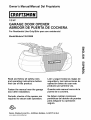 1
1
-
 2
2
-
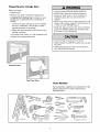 3
3
-
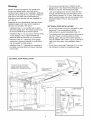 4
4
-
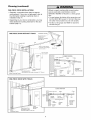 5
5
-
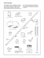 6
6
-
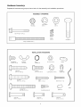 7
7
-
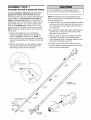 8
8
-
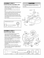 9
9
-
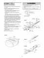 10
10
-
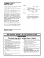 11
11
-
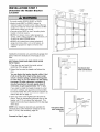 12
12
-
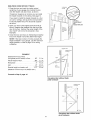 13
13
-
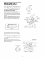 14
14
-
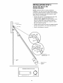 15
15
-
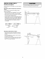 16
16
-
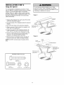 17
17
-
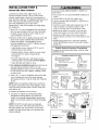 18
18
-
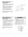 19
19
-
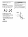 20
20
-
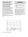 21
21
-
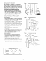 22
22
-
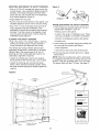 23
23
-
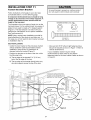 24
24
-
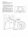 25
25
-
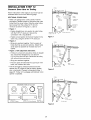 26
26
-
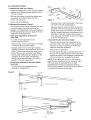 27
27
-
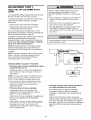 28
28
-
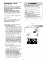 29
29
-
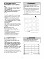 30
30
-
 31
31
-
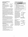 32
32
-
 33
33
-
 34
34
-
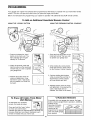 35
35
-
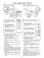 36
36
-
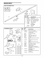 37
37
-
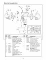 38
38
-
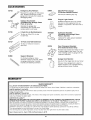 39
39
-
 40
40
-
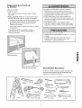 41
41
-
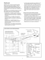 42
42
-
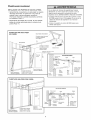 43
43
-
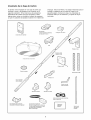 44
44
-
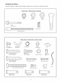 45
45
-
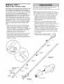 46
46
-
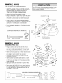 47
47
-
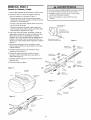 48
48
-
 49
49
-
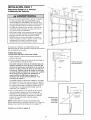 50
50
-
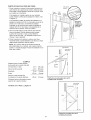 51
51
-
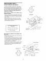 52
52
-
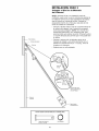 53
53
-
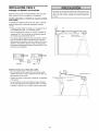 54
54
-
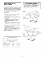 55
55
-
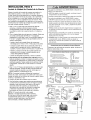 56
56
-
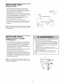 57
57
-
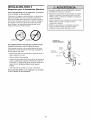 58
58
-
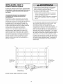 59
59
-
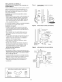 60
60
-
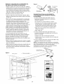 61
61
-
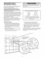 62
62
-
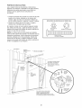 63
63
-
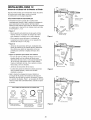 64
64
-
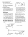 65
65
-
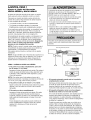 66
66
-
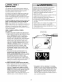 67
67
-
 68
68
-
 69
69
-
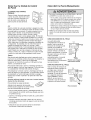 70
70
-
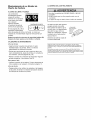 71
71
-
 72
72
-
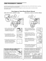 73
73
-
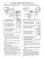 74
74
-
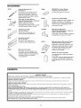 75
75
-
 76
76


Craftsman 139.53989 El manual del propietario
- Categoría
- Abridor de puerta de garage
- Tipo
- El manual del propietario
- Este manual también es adecuado para
en otros idiomas
- English: Craftsman 139.53989 Owner's manual
Artículos relacionados
-
Craftsman 13953985 El manual del propietario
-
Craftsman 139.53930DM El manual del propietario
-
-
-
Craftsman 13953997D El manual del propietario
-
-
-
-