
Shim-lock™ for flush mounting
(eliminates floating) in oversized dry
wall, tile, and panel wall applications
to help comply with NEC 314.21. For
use with electrical wiring devices and
lighting controls with integral mounting
yokes, having mounting slots for insertion
screws.
NOTE: Wall box installation must comply
with NEC 314.20 prior to using Shim-lock.
DIRECTIONS
1. Insert a 6-32 UNC screw into the
mounting slot of the device’s strap.
NOTE: A 6-32 UNC is a standard screw
for installing electrical wiring devices.
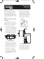
2. Fasten the Shim-lock onto the
screw, with the tab pointing towards
the strap, to an extent that adequate
clearance exists for the Shim-lock
to rotate freely with the screw (refer
to Figure 1). Note: The device needs
to be supported at one end by the
sheetrock to obtain proper restraint.
Figure 1. Shim-lock installation onto
the mounting screw
3. To mount the device into the wall
box, start to fasten the screw into
the corresponding threaded opening
provided on the wall box. Keep
the Shim-lock clear of the strap to
ensure that it rotates with the screw.
4. Turning the screw clockwise or
counter-clockwise would lower or
raise the Shim-lock elevation. Push
the device against the Shim-lock to
check whether proper device orien-
tation is attained.
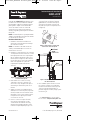
5. If orientation is attained, ensure
that the tab is constrained within
the mounting slot while pushing the
strap firmly against the Shim-lock,
to lock its rotation (refer to Figure 2).
Continue to fasten the screw grad -
ually to capture the strap at the
desired elevation (refer to Figure 3).
Figure 2. Schematic of the shim held
captive in the mounting slot
Figure 3. Device floatation arrested
using the Shim-lock
6. To readjust position, rotate the screw
counter-clockwise while holding
the strap against the Shim-lock to
release the tab from the mounting
slot, and repeat Steps 4 and 5.
Installation Instructions
SHIM-LOCK
™
P/N 340763 Rev. C
340763 RevC_ShimLock IS:340763_RevC_Shimlock IS 10/23/08 10:46 AM Page 1

Instrucciones de Instalación
SHIM-LOCK
™
P/N 340763 Rev. C
Cuña de tope Shim-lock™ para montaje a ras
(elimina la oscilación) en aberturas sobredi-
mensionadas en paneles de pared y azulejos
para ayudar a cumplir con la norma NEC
314.21. Se utilizan con los accesorios de
instalación eléctrica que tienen marco de
montaje integrado y ranuras para los tornillos
de fijación.
NOTA: La instalación de la caja de pared debe
cumplir la norma NEC 314.20 antes de utilizar
la cuña de fijación ‘Shim-lock’.
INSTRUCCIONES DE USO
1. Introducir un tornillo 6-32 UNC en la
ranura de la aleta del marco de montaje
del elemento a instalar.
NOTA: Los tornillos 6-32 UNC son de uso
común y normalizado para accesorios en
instalaciones eléctricas.
2. Introducir la cuña Shim-lock en el tornillo,
con la pestaña hacia la aleta del accesorio
hasta que quede suficiente espacio para
que la cuña gire libremente junto con el
tornillo (véase la Figura 1). Nota: Uno de
los extremos del accesorio de instalación
debe estar apoyado en el panel de
la pared para impedir movimientos
erráticos.
Figura 1: Colocación de la cuña Shim-lock
en el tornillo de fijación.
3. Para montar el accesorio en la caja,
comenzar a enroscar el tornillo en el
orificio de la caja. Asegurarse de que la
Shim-lock gire libremente junto con el
tornillo.
4. Al girar el tornillo en sentido horario o
antihorario acercará o alejará (respectiva-
mente) la Shim-lock a la aleta del marco
de montaje. Fijar la aleta contra la Shim-
lock para verificar que la posición del
accesorio sea correcta.
5. Con el accesorio en la posición final,
verificar que la pestaña de la cuña
esté dentro de la ranura de la aleta y
mantener presionada la misma contra
la Shim-lock para impedir que gire con
el tornillo (véase la Figura 2). Ajustar
gradualmente el tornillo hasta que la
aleta de fijación quede en la posición
deseada con respecto a la pared (véase
la Figura 3).
Figura 2: Ilustración de la cuña de tope
cautiva en la ranura de fijación
Figura 3: Estabilización del accesorio
con cuñas Shim-lock
6. Para cambiar la posición del accesorio
hacer girar el tornillo en sentido anti -
horario sosteniendo la aleta de fijación
contra la cuña de tope para que su
pestaña salga de la ranura; luego repetir
los Pasos 4 y 5.
P/N 340763 Rev. C P. O. Box 4822, Syracuse, NY 13221
Call 800.223.4185 for Technical Support
Visit our website: www.passandseymour.com
340763 RevC_ShimLock IS:340763_RevC_Shimlock IS 10/23/08 10:46 AM Page 2
-
 1
1
-
 2
2


Legrand Shim-lock Guía de instalación
- Tipo
- Guía de instalación
en otros idiomas
- English: Legrand Shim-lock Installation guide
Otros documentos
-
Andersen E4S36WH Guía de instalación
-
Andersen HD2SS30WH Guía de instalación
-
LARSON 15904032 Guía de instalación
-
Feather River Doors FF3780 Guía de instalación
-
TOHATSU MX 50D2 Manual de usuario
-
Feather River Doors 722490-400 Guía de instalación
-
-
Leviton 16R24-1UE Instruction Sheet
-
Bosch Power Tools RA1171 Manual de usuario
-