
1) Remove finials at top of fixture body.
2) Insert washer below metal washer on fixture body.
3) From hole in bottom of glass, place fixture body inside glass.
4) Slip fixture wires from top of fixture body through hole in top
of glass. Slip end of fixture body through hole in top of glass.
5) Replace finials in fixture body.
6) Lower glass down over fixture body. Allow top of glass to
rest on finials.
7) Lower cap down and allow cup to set on top of glass.
8) Slip cap down over end of fixture body protruding from top
of glass. Set cap on top of glass.
9) Pass fixture wire through stem and thread end of stem top
of fixture body.
10) Pass fixture wire through remaining stems and screw stems
together.
NOTE: Thread locking compound must be applied to all
stem threads as noted with symbol (3) to prevent accidental
rotation of fixture during cleaning, relamping, etc.
11) Pass fixture wire through small threaded pipe. Screw end of
threaded pipe into last stem.
12) Pass fixture wire through end of swivel without threaded
pipe. Thread that end of swivel onto end of last stem.
NOTE direction of swivel in accordance with ceiling.
13) Pass fixture wire through hole in canopy. Pass threaded pipe
on end of swivel up through hole in canopy.
14) Pass fixture wire through hole in lockwasher. Thread
lockwasher onto end of threaded pipe protruding from
inside canopy.
15) Pass fixture wire through hole in hexnut. Thread hexnut onto
end of threaded pipe.
16) TURN OFF POWER.
IMPORTANT: Before you start, NEVER attempt any work
without shutting off the electricity until the work is done.
a) Go to the main fuse, or circuit breaker, box in your
home. Place the main power switch in the “OFF”
position.
b) Unscrew the fuse(s), or switch “OFF” the circuit breaker
switch(s), that control the power to the fixture or room
that you are working on.
c) Place the wall switch in the “OFF” position. If the fixture
to be re placed has a switch or pull chain, place those in
the “OFF” position.
17) Find the appropriate threaded holes on mounting strap.
Assemble mounting screws into threaded holes.
18) Attach mounting strap to outlet box. (Screws not provided).
Mounting strap can be adjusted to suit position of fixture.
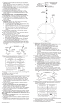
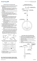
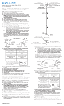
19) Grounding instructions: (See Illus. A or B).
A) On fixtures where mounting strap is provided with a
hole and two raised dimples. Wrap ground wire from
outlet box around green ground screw, and thread into
hole.
B) On fixtures where a cupped washer is provided. Attach
ground wire from outlet box under cupped washer and
green ground screw, and thread into mounting strap.
If fixture is provided with ground wire. Connect fixture
ground wire to outlet box ground wire with wire connector.
(Not provided.) After following the above steps. Never
connect ground wire to black or white power supply wires.
20) Make wire connections (connectors not provided.) Reference
chart below for correct connections and wire accordingly.
GREEN GROUND
SCREW
CUPPED
WASHER
A
B
OUTLET BOX
GROUND
FIXTURE
GROUND
DIMPLES
WIRE CONNECTOR
(NOT PROVIDED)
OUTLET BOX
GROUND
GREEN GROUND
SCREW
FIXTURE
GROUND
Connect Black or
Red Supply Wire to:
Connect
White Supply Wire to:
Black White
*Parallel cord (round & smooth) *Parallel cord (square & ridged)
Clear, Brown, Gold or Black
without tracer
Clear, Brown, Gold or Black
with tracer
Insulated wire (other than green)
with copper conductor
Insulated wire (other than green)
with silver conductor
*Note: When parallel wires (SPT I & SPT II)
are used. The neutral wire is square shaped
or ridged and the other wire will be round in
shape or smooth (see illus.)
Neutral Wire
Date Issued: 3/27/15
IS-42475-US
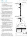
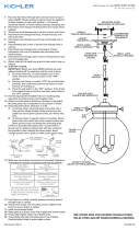
MOUNTING STRAP
ABRAZADERA DE MONTAJE
CANOPY
ESCUDETE
STEM
VARILLA
KNURL KNOB
PERILLA ESTRADA
SWIVEL
UNIÓN GIRATORIA
4
3
3
3
GLASS
VIDRIO
FINIAL
CAPUCHON
HEXNUT
TUERCA HEXAGONAL
LOCKWASHER
ARANDELA DE SEGURIDAD
CAP
TAPA
WASHER
ARANDELA
METAL WASHER
ARANDELA DE METAL
SEE OTHER SIDE FOR SPANISH TRANSLATIONS.
VEA EL OTRO LADO DE TRADUCCIONES AL ESPAÑOL.
We’re here to help 866-558-5706
Hrs: M-F 9am to 5pm EST
21) Push fixture to ceiling, carefully passing mounting screws
through holes in canopy.
22) Thread knurl knobs onto ends of mounting scrwes. Tighten
knurl knobs to secure fixture to ceiling.

1) Retire los capuchones de la parte superior del cuerpo del
artefacto.
2) Inserte la arandela debajo de la arandela de metal en el
cuerpo del artefacto.
3) Desde el agujero en el fondo del vidrio, coloque el cuerpo
del artefacto dentro del vidrio.
4) Deslice los alambres del artefacto desde la parte superior
del cuerpo del artefacto a través del agujero en la parte
superior del vidrio. Deslice el extremo del cuerpo del
artefacto a través del agujero en la parte superior del vidrio.
5) Reemplace los capuchones en el cuerpo del artefacto.
6) Baje el vidrio sobre el cuerpo del artefacto. Permita que la
parte superior del vidrio descanse en los capuchones.
7) Baje la tapa y permita que la tapa se asiente encima del
vidrio.
8) Deslice la tapa hacia abajo sobre el extremo del cuerpo del
artefacto que sobresale de la parte superior del vidrio.
Coloque la tapa encima del vidrio.
9) Pase el alambre del artefacto a través del vástago y rosque
el extremo del vástago en la parte superior del cuerpo del
artefacto.
10) Pase el cable del artefacto a través de los vástagos y
vástagos de tornillo. NOTA: El compuesto para rosca
estanca se debe aplicar a todas las roscas del vástago
como se notó con el símbolo (3) para impedir la rotación
accidental del artefacto durante la limpieza, instalación de
una bombilla nueva, etc.
11) Pase el alambre del artefacto a través del tubo roscada
pequeña. Atornille el tubo roscado en el último vástago.
12) Pase el alambre del artefacto hasta el final del unión
giratoria sin el tubo roscado. Enrosque el unión giratoria en
el extremo del vástago último. NOTE la dirección de la
unión giratoria de acuerdo con el cielo raso.
13) Pase el alambre del artefacto a través del agujero en el
escudete. Pase el tubo roscado en el extremo del unión
giratoria a través del agujero en el escudete.
14) Pase el alambre del artefacto a través del agujero en la
arandela de seguridad. Rosque la arandela de seguridad
dentro del extremo del tubo roscado que sobresale del
escudete interior.
15) Pase el alambre del artefacto a través del agujero en la tuerca
hexagonal. Rosque la tuerca hexagonal sobre el extremo del
tubo roscado.
16) APAGUE LA ALIMENTACIÓN ELÉCTRICA.
IMPORTANTE: Antes de comenzar, NUNCA trate de trabajar
sin antes desconectar la corriente hasta que el trabajo se
termine.
a) Vaya a la caja principal de fusibles, o interruptor o caja
de circuitos de su casa. Coloque el interruptor de la
corriente principal en posición de apagado “OFF”.
b) Desatornille el (los) fusible (s), o coloque el interruptor o
interruptores del breaker en posición de apagado “OFF”,
que controla (n) la corriente hacia el artefacto o habitación
donde está trabajando.
c) Coloque el interruptor de pared en posición de apagado
“OFF”. Si el artefacto que se va a reemplazar tiene un
interruptor o cadena que se jala, colóquelos en la
posición de apagado “OFF”.
17) Ensamble los tornillos de montaje en los orificios roscados
en la barra de montaje.
18) Unir la abrazadera de montaje a la caja de conexiones. (No
se proveen tornillos). La abrazadera de montaje puede
ajustarse para acomodar la posición del artefacto.
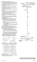
19) Instrucciones de conexión a tierra solamente para los
Estados Unidos.
(Vea la ilustracion A o B).
A) En las lámparas que tienen el fleje, de montaje con un
agujero y dos hoyue los realzados. Enrollar el alambre a
tierra de la caja tomacorriente alrededor del tornillo
verde y pasarlo por el aquiero.
B) En las lámparas con una arandela acopada. Fijar el
alambre a tierra de la caja tomacorriente del ajo de la
arandela acoada y tornillo verde, y paser por el fleje de
montaje.
Si la lámpara viene con alambre a tierra. Conecter el
alambre a tierra de la lámpara al alambre a tierra de la caja
tomacorriente con un conector de alambres (no incluido)
espués de seguir los pasos anteriores. Nunca conectar el
alambra a tierra a los alambres eléctros negro o blanco.
Date Issued: 3/27/15
IS-42475-US
20) Haga les conexiones de los alambres (no se proveen los
connectores.) La tabla de referencia de abajo indica las
conexiones correctas y los alambres correspondientes.
21) Empuje el artefacto hacia el techo, pasando cuidadosamente
los tornillos de montaje a través de los orificios en el
escudete.
22) Atornille las perillas estriadas en los tornillos de montaje.
Ajuste las perillas estriadas para fijar el artefacto en el techo.
ARANDELA
CONCAVA
A
B
TIERRA DE LA
CAJA DE SALIDA
TORNILLO DE TIERRA,
VERDE
DEPRESIONES
TIERRA
ARTEFACTO
CONECTOR DE ALAMBRE
(NO SE PROVEE)
TIERRA DE LA
CAJA DE SALIDA
TORNILLO DE TIERRA,
VERDE
TIERRA
ARTEFACTO
Conectar el alambre de
suministro negro o rojo al
Conectar el alambre de
suministro blanco al
Negro Blanco
*Cordon paralelo (redondo y liso)
*Cordon paralelo (cuadrado y estriado)
Claro, marrón, amarillio o negro
sin hebra identificadora
Claro, marrón, amarillio o negro
con hebra identificadora
Alambre aislado (diferente del verde)
con conductor de cobre
Alambre aislado (diferente del
verde) con conductor de plata
*Nota: Cuando se utiliza alambre paralelo
(SPT I y SPT II). El alambre neutro es de forma
cuadrada o estriada y el otro alambre será de
forma redonda o lisa. (Vea la ilustracíón).
Hilo Neutral
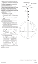
SEE OTHER SIDE FOR ENGLISH TRANSLATIONS.
VEA EL OTRO LADO DE TRADUCCIONES AL INGLÉS.
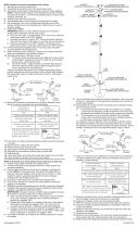
MOUNTING STRAP
ABRAZADERA DE MONTAJE
CANOPY
ESCUDETE
STEM
VARILLA
KNURL KNOB
PERILLA ESTRADA
SWIVEL
UNIÓN GIRATORIA
4
3
3
3
GLASS
VIDRIO
FINIAL
CAPUCHON
HEXNUT
TUERCA HEXAGONAL
LOCKWASHER
ARANDELA DE SEGURIDAD
CAP
TAPA
WASHER
ARANDELA
METAL WASHER
ARANDELA DE METAL
We’re here to help 866-558-5706
Hrs: M-F 9am to 5pm EST
-
 1
1
-
 2
2


Kichler Lighting 42475OZMER Manual de usuario
- Tipo
- Manual de usuario
- Este manual también es adecuado para
en otros idiomas
Artículos relacionados
-
 Kichler Lighting 43190AUB Manual de usuario
-
 Kichler Lighting 43185AUB Manual de usuario
-
 Kichler Lighting 42167OZWH Manual de usuario
-
 Kichler Lighting 42190OZ Manual de usuario
-
 Kichler Lighting 43328DAG Manual de usuario
-
 Kichler Lighting 42588OZ Manual de usuario
-
 Kichler Lighting 42044OZWH Manual de usuario
-
 Kichler Lighting 42047NBR Manual de usuario
-
Kichler Lighting 49669WZC Manual de usuario


