La página se está cargando...

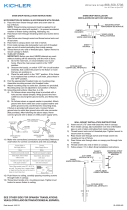
MOUNTING STRAP
ABRAZADERA DE MONTAJE
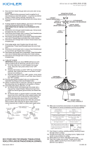
1) Pass wire from fixture through stem and screw stem to
coupling on top of fixture body.
NOTE: Thread locking compound must be applied to all
stem threads as noted with symbol () to prevent accidental
rotation of fixture during cleaning, relamping, etc.
2) Pass fixture wire through remaining stems and screw stems
together.
3) Pass fixture wire through the swivel and canopy assembly.
Thread end of swivel into last stem.
NOTE DIRECTION OF SWIVEL IN ACCORDANCE WITH
CEILING.
4) TURN OFF POWER.
IMPORTANT: Before you start, NEVER attempt any work
without shutting off the electricity until the work is done.
a) Go to the main fuse, or circuit breaker, box in your
home. Place the main power switch in the “OFF” position.
b) Unscrew the fuse(s), or switch “OFF” the circuit breaker
switch(s), that control the power to the fixture or room
that you are working on.
c) Place the wall switch in the “OFF” position. If the fixture
to be replaced has a switch or pull chain, place those in
the “OFF” position.
5) Find the appropriate threaded holes on mounting strap.
Assemble driver bracket using the screws provided to the
mounting strap.
6) Attach mounting strap to outlet box. (Screws not provided).
Mounting strap can be adjusted to suit position of fixture.
7) Grounding instructions: (See Illus. A or B).
A) On fixtures where mounting strap is provided with a hole
and two raised dimples. Wrap ground wire from outlet
box around green ground screw, and thread into hole.
B) On fixtures where a cupped washer is provided. Attach
ground wire from outlet box under cupped washer and
green ground screw, and thread into mounting strap.
If fixture is provided with ground wire. Connect fixture
ground wire to outlet box ground wire with wire connector.
(Not provided.) After following the above steps. Never
connect ground wire to black or white power supply wires.
8) Make primary wire connections (connectors not provided)
joining the white driver wire to the white supply wire, and the
black driver wire to the black supply wire. DO NOT CONNECT
THE RED AND BLUE SECONDARY WIRES TO THE SUPPLY
WIRES.
9) Make the secondary wire connections (red and blue driver
wires to fixture wire) using the provided wire nuts, trimming
fixture wires if necessary. Reference chart below for correct
connections and wire accordingly.
10) Separate the primary and secondary connections, ensuring
that they remain on opposite sides of the driver while
bringing the fixture to the ceiling.
11) Align the side canopy holes with the driver bracket, and
secure the fixture to the ceiling be installing both of the
mounting screws.
Connect Secondary
BLUE Driver Wire to:
Connect Secondary
RED Driver Wire to:
Blue or Black Red or White
*Parallel cord (round & smooth) *Parallel cord (square & ridged)
Clear, Brown, Gold or Black
without Tracer
Clear, Brown, Gold or Black
with Tracer
Insulated wire (other than green)
with copper conductor
Insulated wire (other than green)
with silver conductor
*Note: When parallel wire (SPT I & SPT II)
are used. The neutral wire is square shaped
or ridged and the other wire will be round in
shape or smooth (see illus.) Neutral Wire
Date Issued: 3/21/14 IS-42517-US
CANOPY
ESCUDETE
STEM
VÁSTAGO
SWIVEL
UNIÓN GIRATORIA
4
FIXTURE BODY
CUERPO DEL ARTEFACTO
SEE OTHER SIDE FOR SPANISH TRANSLATIONS.
VEA EL OTRO LADO DE TRADUCCIONES AL ESPAÑOL.
GREEN GROUND
SCREW
CUPPED
WASHER
AB
OUTLET BOX
GROUND
FIXTURE
GROUND
DIMPLES
WIRE CONNECTOR
(NOT PROVIDED)
OUTLET BOX
GROUND
GREEN GROUND
SCREW
FIXTURE
GROUND
We’re here to help 866-558-5706
Hrs: M-F 9am to 5pm EST
SCREW
TORNILLO
DRIVER BRACKET
SOPORTE DEL
CONTROLADOR DRIVER
CONTROLADOR

1) Pase el alambre del artefacto a través del vástago y atornille
el vástago al tope del artefacto. NOTA: El compuesto para
rosca estanca se debe aplicar a todas las roscas del
vástago como se notó con el símbolo () para impedir la
rotación accidental del artefacto durante la limpieza,
instalación de una bombilla nueva, etc.
2) Pase el alambre del artefacto a través de los vástagos
restantes y atornille los vástagos juntos.
3) Pase el alambre del artefacto a través del unión giratoria y el
escudete ensamblaje. Atornillar el extremo del unión
giratoria en el último vástago.
OBSERVE LA DIRECCIÓN DE LA UNIÓN GIRATORIA DE
ACUERDO CON EL TECHO.
4) APAGUE LA ALIMENTACIÓN ELÉCTRICA.
IMPORTANTE: Antes de comenzar, NUNCA trate de trabajar
sin antes desconectar la corriente hasta que el trabajo se
termine.
a) Vaya a la caja principal de fusibles, o interruptor o caja
de circuitos de su casa. Coloque el interruptor de la
corriente principal en posición de apagado “OFF”.
b) Desatornille el (los) fusible (s), o coloque el interruptor o
interruptores del breaker en posición de apagado
“OFF”, que controla (n) la corriente hacia el artefacto o
habitación donde está trabajando.
c) Coloque el interruptor de pared en posición de apagado
“OFF”. Si el artefacto que se va a reemplazar tiene un
interruptor o cadena que se jala, colóquelos en la
posición de apagado “OFF”.
5) Encontrar los agujeros roscados correctos en la abrazadera
de montaje. Instalar los tornillos de montaje en los agujeros
roscados.
6) Unir la abrazadera de montaje a la caja de conexiones. (No
se proveen tornillos). La abrazadera de montaje puede
ajustarse para acomodar la posición del artefacto.
7) Instrucciones de conexión a tierra solamente para los
Estados Unidos. (Vea la ilustracion A o B).
A) En las lámparas que tienen el fleje, de montaje con un
agujero y dos hoyue los realzados. Enrollar el alambre a
tierra de la caja tomacorriente alrededor del tornillo verde y
pasarlo por el aquiero.
B) En las lámparas con una arandela acopada. Fijar el
alambre a tierra de la caja tomacorriente del ajo de la
arandela acoada y tornillo verde, y paser por el fleje de
montaje.
Si la lámpara viene con alambre a tierra. Conecter el
alambre a tierra de la lámpara al alambre a tierra de la caja
tomacorriente con un conector de alambres (no incluido)
espués de seguir los pasos anteriores. Nunca conectar el
alambra a tierra a los alambres eléctros negro o blanco.
8) Haga las conexiones de alambre primarias (no se proporcionan
los conectores) uniendo el alambre blanco del controlador
al alambre blanco de suministro, y el alambre negro del
controlador al alambre negro de suministro. NO CONECTE
LOS ALAMBRES ROJO Y AZUL SECUNDARIOS A LOS
ALAMBRES DE SUMINISTRO.
Date Issued: 3/21/14 IS-42517-US
ARANDELA
CONCAVA
AB
TIERRA DE LA
CAJA DE SALIDA
TORNILLO DE TIERRA,
VERDE
DEPRESIONES
TIERRA
ARTEFACTO
CONECTOR DE ALAMBRE
(NO SE PROVEE)
TIERRA DE LA
CAJA DE SALIDA
TORNILLO DE TIERRA,
VERDE
TIERRA
ARTEFACTO
Conectar el alambre de
suministro negro o rojo al
Conectar el alambre de
suministro blanco al
Negro Blanco
*Cordon paralelo (redondo y liso) *Cordon paralelo (cuadrado y estriado)
Claro, marrón, amarillio o negro
sin hebra identificadora
Claro, marrón, amarillio o negro
con hebra identificadora
Alambre aislado (diferente del verde)
con conductor de cobre
Alambre aislado (diferente del
verde) con conductor de plata
*Nota: Cuando se utiliza alambre paralelo
(SPT I y SPT II). El alambre neutro es de forma
cuadrada o estriada y el otro alambre será de
forma redonda o lisa. (Vea la ilustracíón). Hilo Neutral
SEE OTHER SIDE FOR ENGLISH TRANSLATIONS.
VEA EL OTRO LADO DE TRADUCCIONES AL INGLÉS.
9) Haga las conexiones de alambre secundarias (alambres
rojo y azul del controlador al alambre del artefacto)
utilizando las tuercas para alambre proporcionadas,
recortando los alambres del artefacto si es necesario.
Consulte la gráfica a continuación para las conexiones
correctas y alámbrelas en consecuencia.
10) Separe las conexiones primaria y secundaria, asegurando
que ellas permanecen en los lados opuestos del controlador
mientras se lleva al artefacto hacia el techo.
11) Alinee los agujeros del escudete con el soporte del
controlador, y asegure el artefacto al techo mediante la
instalación de ambos tornillos de montaje.
We’re here to help 866-558-5706
Hrs: M-F 9am to 5pm EST
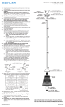
MOUNTING STRAP
ABRAZADERA DE MONTAJE
CANOPY
ESCUDETE
STEM
VÁSTAGO
SWIVEL
UNIÓN GIRATORIA
4
FIXTURE BODY
CUERPO DEL ARTEFACTO
SCREW
TORNILLO
DRIVER BRACKET
SOPORTE DEL
CONTROLADOR DRIVER
CONTROLADOR
1/2