
Sony Corporation 1997 Printed in Malaysia
3-859-490-11 (1)
23
× 1
× 1 × 1
1
4
FM/MW/SW
Cassette Car
Stereo
XR-C450
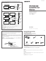
If you connect and optional power amplifier and do not use the built-in amplifier, the beep-tone will be disabled.
For connecting two or more changers, the source selector XA-C30 (optional) and the BUS cable RC-61 (1 m) or RC-62 (2 m)
(optional) are necessary.
Si conecta un amplificador opcional de potencia y no utiliza el incorporado, el pitido se desactivará.
Cuando desee conectar dos o más cambiadores, necesitará un selector de fuente XA-C30 (opcional) y un cable BUS RC-61 (1 m)
o RC-62 (2 m) (opcional).
Connection diagram/Diagrama de conexiones/
BUS CONTROL IN
BUS AUDIO IN
BUS
CONTROL IN
BUS AUDIO
IN
LINE OUT
REAR
LINE OUT
FRONT
XR-C450
XR-C450
× 1
5
× 1
6
× 1
7
Note for Connecting
If there is alternator noise (a whining sound when raising engine speed), ground the master unit by
connecting it to a metal point of the car with the supplied chassis ground cord 7. Connect the
ground cord to the master unit with part 2 as shown in the illustration.
Nota sobre conexión
Si el alternador emite ruido (un zumbido al aumentar la velocidad del motor), conecte la unidad
principal a tierra y, para ello, enchúfela a un punto de metal del automóvil mediante el cable de toma
a tierra del chasis 7 suministrado. Conecte el cable de toma a tierra a la unidad principal con la pieza
2 como se muestra en la ilustración.
7
2
2
7
To a metal point of the car
A un punto de metal del automóvil
Installation/Connections
Instalación/Conexiones
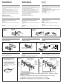
Parts for Installation and Connections
Componentes de montaje y conexiones
The numbers in the list are keyed to those in the instructions.
Los números de la lista corresponden a los de las instrucciones.
The release key 5 is used for dismounting the unit. See the Operating Instructions manual for details.
La llave de liberación 5 se utiliza para desmontar la unidad. Con respecto a los detalles, consulte el
manual de instrucciones.
5
Caution
Cautionary notice for handling the bracket 1. Handle the bracket carefully to avoid injuring your
fingers.
Precaución
Advertencia sobre la manipulación del soporte 1. Tenga mucho cuidado al manipular el soporte para
evitar posibles lesiones en los dedos.
1
× 5
(incl. 1 reserve)
(se incluyen 1 de reserva)
Example 1 / Ejemplo 1 /
CD/MD changer
Cambiador de CD/MD
Front speakers
Altavoces
delanteros
Rear speakers
Altavoces
traseros
Example 2 / Ejemplo 2 /
CD/MD changer
Cambiador de CD/MD
Source selector XA-C30
Selector de fuente
XA-C30
XA-C30
CD changer
Cambiador de CD
Power amplifier
Amplificador de potencia
Power amplifier
Amplificador de potencia
Rear speakers
Altavoces
traseros
Rear speakers
Altavoces
traseros
Front speakers
Altavoces
delanteros
Front speakers
Altavoces
delanteros

182 mm
53 mm
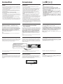
Installation
Precautions
•Do not tamper with the four holes on the upper surface of the unit.
They are used for tuner adjustments to be made only by service
technicians.
• Choose the installation location carefully so the unit will not
hamper the driver during driving.
• Avoid installing the unit where it would be subject to high
temperatures, such as from direct sunlight or hot air from the
heater, or where it would be subject to dust, dirt or excessive
vibration.
• Use only the supplied mounting hardware for safe and secure
installation.
Mounting angle adjustment
Adjust the mounting angle to less than 20°.
Instalación
Precauciones
•No toque los cuatro orificios de la superficie superior de la unidad.
Estos orificios son para ajustes del sintonizador que solamente
deberán realizar técnicos de reparación.
• Elija cuidadosamente el lugar de montaje de forma que la unidad
no interfiera las funciones normales de conducción.
• Evite instalar la unidad donde pueda quedar sometida a altas
temperaturas como las de la luz solar directa y el aire caliente de la
calefacción, o a polvo, suciedad y vibraciones excesivas.
• Para realizar una instalación segura y firme, utilice solamente la
ferretería de montaje suministrada.
Ajuste del ángulo de montaje
Ajuste el ángulo de montaje a menos de 20°.
Forma de extraer e instalar el panel frontal
Antes de instalar la unidad, extraiga el panel frontal.
Para extraerlo
Presione la tecla RELEASE a fin de abrir el panel frontal, y tire de él
hacia afuera.
Para instalarlo
Alinee las partes A y B, y presione el panel frontal hasta que
chasquee.
How to Detach and Attach the Front Panel
Before installing the unit, detach the front panel.
To detach
Press the RELEASE button to open up the front panel, then pull it
out.
To attach
Align parts A and B, and push the front panel in until it clicks.
B
Ejemplo de montaje
Instalación en el salpicadero
12
3
A
Mounting Example
Installation in the dashboard
Montaje de la unidad en un automóvil
japonés
Usted no podrá instalar esta unidad en algunos automóviles
japoneses. En tal caso, consulte a su proveedor Sony.
Mounting the Unit in a Japanese Car
This unit may not be installed in some makes of cars. In this case,
consult your nearest Sony dealer.
1
2
3
•
•
•
•
A B
To detach
para extraerlo
To attach
para instalarlo
Fire wall
Panel cortafuegos
Dashboard
Salpicadero
Bend these claws, if necessary.
Si es necesario, doble estas uñas.
1 Run a blade along the slits on
the back of the front trim and
cut it off of the unit.
Pase una cuchilla a lo largo de
las ranuras de la parte posterior
del adorno frontal y córtelo.
NISSAN
2 TOYOTA
4*
max. size
M5 × 8mm
Tamaño
máx.
M5 × 8mm
5 × 8 mm
Bracket
Soporte
4*
max. size
M5 × 8mm
Tamaño
máx.
M5 × 8mm
5 × 8 mm
to dashboard/center console
al salpicadero/consola central
Bracket
Soporte
4*
max. size
M5 × 8mm
Tamaño
máx.
M5 × 8mm
5 × 8 mm
Bracket
Soporte
4*
max. size
M5 × 8mm
Tamaño
máx.
M5 × 8mm
5 × 8 mm
to dashboard/center console
al salpicadero/consola central
Slit
Ranura
Existing parts supplied with your car
Piezas existentes suministradas con su automóvil
Existing parts supplied with your car
Piezas existentes suministradas con su automóvil
Bracket
Soporte
* To the prevent malfunction, install only with the supplied screws 4. Do not use an electric
or impact screwdriver.
* Para evitar que se produzcan fallos, realice la instalación solamente con los tornillos
suministrados 4. No utilice un destornillador eléctrico o de impacto.
* 4
RELEASE button
Tecla RELEASE

Connection
Caution
• This unit is designed for negative ground 12 V DC operation only.
• Before making connections, disconnect the ground terminal of the
car battery to avoid short circuits.
• Connect the yellow and red power input leads only after all other
leads have been connected.
• Be sure to connect the red power input lead to the positive 12 V
power terminal which is energized when the ignition key is in the
accessory position.
• Run all ground wires to a common ground point.
• Connect the yellow cord to a free car circuit rated higher than the
unit’s fuse rating.
If you connect this unit in series with other stereo components, the
car circuit they are connected to must be rated higher than the sum
of the individual component’s fuse rating.
If there are no car circuits rated as high as the unit’s fuse rating,
connect the unit directly to the battery.
If no car circuits are available for connecting this unit, connect the
unit to a car circuit rated higher than the unit’s fuse rating in such a
way that if the unit blows its fuse, no other circuits will be cut off.
If your car has no accessory position on the
ignition key switch — POWER SELECT switch
The illumination on the front panel is factory set to be turned on
even while the unit is not in use. However, this setting may cause
some car battery wear if your car has no accessory position on the
ignition key switch. To avoid this battery wear, set the POWER
SELECT switch located on the bottom of the unit to the B
position, then press the reset button. The illumination is reset to
stay off while the unit is not in use.
Note
The caution alarm for the front panel is not activated when the POWER SELECT
switch is set to the B position.
Frequency select switch
The MW (FM) tuning interval is factory-set to the 9K (50 K) position.
If the frequency allocation system of your country is based on 10 kHz
(200 kHz) interval, set the switch on the bottom of the unit to the
10 K (200 K) position before making connections.
When you change the position of the switch, be sure to press one of the reset button
after the connections are complete.
Reset button
When the installation and connections are complete, be sure to press
the reset button with a ballpoint pen etc. The reset button is located
on the left of the connector on the unit side when the front panel is
detached.
Conexiones
Precauciones
• Esta unidad ha sido diseñada para alimentarse con 12 V CC,
negativo a masa, solamente.
• Antes de realizar las conexiones, desconecte el terminal de puesta a
masa de la batería del automóvil a fin de evitar cortocircuitos.
• Conecte los cables conectores de alimentación amarillo y rojo
solamente después de haber conectado los demás.
• Cerciórese de conectar el cable conector de alimentación rojo a un
terminal de 12 V positivo que se energice al poner la llave de
encendido en la posición para accesorios.
• Conecte todos los conductores de puesta a masa a un punto
común.
• Conecte el cable amarillo a un circuito libre del automóvil que
tenga una capacidad superior a la del fusible de la unidad.
Si conecta esta unidad en serie con otros componentes de estéreo, el
circuito del automóvil al que se encuentran conectados debe tener
una capacidad superior a la de la suma de las capacidades de los
fusibles de cada componente.
Si ningún circuito del automóvil tiene una capacidad tan alta como
la del fusible de la unidad, conecte ésta directamente a la batería.
Si el automóvil no dispone de ningún circuito para conectar esta
unidad, conéctela a un circuito con una capacidad superior a la del
fusible de la unidad de tal manera que si se funde el fusible de ésta,
no se cortará ningún otro circuito.
Si el automóvil no dispone de posición para
accesorios en la llave de encendido
— Selector POWER SELECT
La iluminación del panel frontal ha sido ajustada en fábrica para que
esté activada aunque la unidad no se encuentre en reproducción. Sin
embargo, este ajuste puede provocar cierta descarga de la batería del
automóvil si éste no dispone de posición para accesorios en la
llave de encendido. Para evitar esto, ponga el selector POWER
SELECT, situado en la base de la unidad, en la posición B y,
después, presione el botón de reposición. La iluminación estará
desactivada cuando la unidad no se encuentre en reproducción.
Nota
La alarma de precaución del panel frontal no se activará cuando el selector POWER
SELECT se encuentre en la posición B .
Selector de frecuencia
El intervalo de sintonía de MW (FM) ha sido ajustado en fábrica a la
posición 9 K (50 K). Si el sistema de asignación de frecuencias de su
país se basa en el intervalo de 10 kHz (200 kHz), ponga este selector,
situado en la base de la unidad, en la posición 10 K (200 K) antes de
realizar las conexiones.
Cuando haya cambiado la posición del selector, cerciórese de presionar uno de los
botones de reposición después de haber finalizado las conexiones.
Botón de reposición
Cuando haya finalizado la instalación y las conexiones, cerciórese de
presionar el botón de reposición con un boligrafo, etc. El botón de
reposición se encuentra a la izquierda del conector de la parte lateral de
la unidad, una vez extraido el del panel frontal.
•
•
•
•
•
•
—
B
B
Reset button
Botón de reposición
POWER SELECT and frequency select switch
POWER SELECT y selector de frecuencia
Change the position with a jeweler’s screwdriver, etc.
Cambie la posición con un destornillador de relojero, etc.

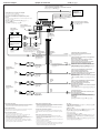
Connection example Ejemplo de conexiones
Front speakers
Altavoces delanteros
AMP REM
to the power antenna control lead or power supply lead of
antenna booster amplifier
<Note> In case of without power antenna, or antenna
booster, not necessary to connect this lead.
al cable de control de la antena motorizada, o al cable de
fuente de alimentación del amplificador de antena
<Nota>En caso de no instalar la antena motorizada o el
amplificador de antena, no es necesario conectar este cable.
ANT REM
LINE OUT REAR
LINE OUT FRONT
BUS CONTROL IN
REMOTE IN
ANT
BUS AUDIO IN
TEL MUTE
Purple striped
Con raya violeta
Green striped
Con raya verde
Gray striped
Con raya gris
White striped
Con raya blanca
6
Notes on the control leads
• The power antenna control lead (blue) supplies +12 V DC when you turn on the
tuner or when you activate the ATA (Automatic Tuner Activation) Function.
• A power antenna without a relay box cannot be used with this unit.
Memory hold connection
When the yellow power input lead is connected, power will always be supplied to
the memory circuit even when the ignition switch is turned off.
Notes on speaker connection
• Before connecting the speakers, turn the unit off.
• Use speakers with an impedance of 4 to 8 ohms, and with adequate power
handling capacities. Otherwise, the speakers may be damaged.
• Do not connect the terminals of the speaker system to the car chassis, and do not
connect the terminals of the right speaker with those of the left speaker.
• Do not attempt to connect the speakers in parallel.
• Do not connect any active speakers (with built-in amplifiers) to the speaker
terminals of the unit. Doing so may damage the active speakers. Therefore, be
sure to connect passive speakers to these terminals.
Notas sobre los conductores de control
• El conductor de control de la antena motorizada (azul) suministrará +12 V CC
cuando conecte la alimentación del sintonizador o cuando active la función de
activación automática del sintonizador (ATA).
• Con esta unidad no podrá utilizarse una antena motorizada sin caja de relés.
Conexión para protección de la memoria
Si conecta el conductor de entrada amarillo, el circuito de la memoria recibirá
siempre alimentación, incluso aunque ponga la llave de encendido en la posición
OFF.
Notas sobre la conexión de los altavoces
• Antes de conectar los altavoces, desconecte la alimentación de la unidad.
• Utilice altavoces con una impedancia de 4 a
8 ohmios, y con la potencia máxima admisible adecuada, ya que de lo contrario
podría dañarlos.
• No conecte los terminales del sistema de altavoces al chasis del automóvil, ni los
del altavoz izquierdo a los del derecho.
• No intente conectar los altavoces en paralelo.
• No conecte altavoces activos (con amplificador incorporado) a los terminales de
altavoces de la unidad. Si lo hiciese, podría dañar tales altavoces. Por lo tanto,
cerciórese de conectar altavoces pasivos a estos terminales.
Rotary remote RM-X2S (not supplied)
Mando rotativo
RM-X2S
(no suministrado)
To AMP REMOTE IN of an optinal power amplifier.
This connection is only for amplifiers.
Connecting any other system may damage the unit.
Para conectar a AMP REMOTE IN del amplificador de potencia
opcional.
Esta conexión es sólo para amplificadores. La conexión de cualquier otro sistema
puede dañar la unidad.
•
•
•
•
•
•
•
to a metal point of the car
First connect the black earth lead, then connect the yellow
and red power input leads.
a un punto metálico del automóvil
En primer lugar conecte el conductor de puesta a tierra negro
y, a continuación, los cables de entrada de alimentación
amarillo y rojo.
Black
Negro
to the +12 V power terminal which is energized at all times
Be sure to connect the black earth lead first.
a un terminal de alimentación de +12V que esté
permanentemente energizado
Asegúrese de conectar primero a este terminal el conductor de
puesta a masa negro
Yellow
Amarillo
to the +12 V power terminal which is energized in the
accessory position on the ignition switch
Be sure to connect the black earth lead first.
a un terminal de alimentación de +12 V que se energice en la
posición para accesorios de la llave de encendido
Asegúrese de conectar primero a este terminal el conductor de
puesta a masa negro
Red
Rojo
Max. supply current 0.1 A
Corriente máx. de alimentación de 0,1 A
Blue
Azul
to the interface cable of a car telephone
al cable de interfaz de un teléfono para automóvil
Light blue
Azul celeste
Fuse (10 A)
Fusible (10 A)
RCA pin cord (RC-63 (1 m), RC-64 (2 m) or
RC-65 (5 m)) (not supplied)
Cable con clavijas RCA (RC-63 (1 m), RC-64
(2 m) o RC-65 (5 m)) (no suministrado)
Blue/white striped
Con raya azul/blanca
Max. supply current 0.3 A
Corriente máx. de
alimentación de 0,3 A
Left
Izquierdo
Front speakers
Altavoces delanteros
Right
Derecho
Right
Derecho
Left
Izquierdo
Rear speakers
Altavoces traseros
from car antenna
de la antena del automóvil
Rear speakers
Altavoces traseros
Power amplifier
Amplificador de potencia
Power amplifier
Amplificador de potencia
RCA pin cord (Supplied with CD/MD changers)
Cable con clavijas RCA (suministrado con un cambiador de CD/MD)
CD/MD changer
Cambiador de CD/MD
BUS cable (supplied with CD/MD changers)
Cable BUS (suministrado con un cambiador de CD/MD)
Transcripción de documentos
Connection diagram/Diagrama de conexiones/スuク sアオ、雜 マ 3-859-490-11 (1) Example 1 / Ejemplo 1 /ィメ 1 Front speakers BUS AUDIO IN Altavoces delanteros FM/MW/SW Cassette Car Stereo ォeエュチnセケ CD/MD changer Cambiador de CD/MD CD/MD ツ犇ォセケ XR-C450 Rear speakers Altavoces traseros BUS CONTROL IN ォ盒ュチnセケ Example 2 / Ejemplo 2 /ィメ 2 Installation/Connections Front speakers Power amplifier Amplificador de potencia CD/MD changer Cambiador de CD/MD CD/MD ツ犇ォセケ ・¥イvゥ jセケ BUS AUDIO IN ヲwクヒ。™スuク ァウsアオ ォeエュチnセケ LINE OUT FRONT Source selector XA-C30 Selector de fuente XA-C30 ュオキスソ ワセケ XA-C30 Instalación/Conexiones Altavoces delanteros Front speakers Altavoces delanteros ォeエュチnセケ XR-C450 Rear speakers BUS CONTROL IN Altavoces traseros LINE OUT REAR ォ盒ュチnセケ Rear speakers Power amplifier Amplificador de potencia CD changer Cambiador de CD CD ツ犇ォセケ ・¥イvゥ Altavoces traseros jセケ ォ盒ュチnセケ If you connect and optional power amplifier and do not use the built-in amplifier, the beep-tone will be disabled. For connecting two or more changers, the source selector XA-C30 (optional) and the BUS cable RC-61 (1 m) or RC-62 (2 m) (optional) are necessary. Si conecta un amplificador opcional de potencia y no utiliza el incorporado, el pitido se desactivará. Cuando desee conectar dos o más cambiadores, necesitará un selector de fuente XA-C30 (opcional) y un cable BUS RC-61 (1 m) o RC-62 (2 m) (opcional). ヲpェGウsアオ、 F、 @ソ ハ・ ¥ イvゥ jセケヲモ、」・ホ、 コクヒェコゥ jセケ。 MァYアN、」 オo ・Xケハチn。 ュ n ウ sアオィ箝モ。 Mゥホィ箝モ ・ H、 Wェコエォコミセケョノ。 Mォ K カキィマ ・ ホチ n キスソ ワセケ XA-C30。] ソ ハ ・ 。] 2ヲフ。 ^。] ソ ハ・ ^。 XR-C450 ^ゥ MBUS ケq ニRC-61。]1 l ヲフ。 ^ゥホ RC-62 Note for Connecting If there is alternator noise (a whining sound when raising engine speed), ground the master unit by connecting it to a metal point of the car with the supplied chassis ground cord 7. Connect the ground cord to the master unit with part 2 as shown in the illustration. Nota sobre conexión Si el alternador emite ruido (un zumbido al aumentar la velocidad del motor), conecte la unidad principal a tierra y, para ello, enchúfela a un punto de metal del automóvil mediante el cable de toma a tierra del chasis 7 suministrado. Conecte el cable de toma a tierra a la unidad principal con la pieza 2 como se muestra en la ilustración. Sony Corporation 1997 Printed in Malaysia Parts for Installation and Connections Componentes de montaje y conexiones ヲwクヒ、ホスuク sアオ・ホェコケs・ The numbers in the list are keyed to those in the instructions. Los números de la lista corresponden a los de las instrucciones. 、Uュアケマェ フェコクケスXゥMサ。ゥ 螟、ェコクケスXャロヲP。 2 1 3 ウ sアオカキェセ ヲpェGオoイ {ヲウ ・ 谺 yチn。] キ Tィョオoーハセ [ウ tョノオo ・ ヘェコュ n。 ^ョノ。 M スミ ・ ホェ™アaェコゥウスLアオヲaスu アN 7 ・ サセ オヲaィお T ィョェコェ ンィョナ魑。、 タ。ァQ ・ ホヲp ケマゥメ ・ ワウ。 ・ ウsアオ 2 ・D セ コアオヲaスu。 ×1 ×1 5 4 ×1 6 7 2 ×5 (incl. 1 reserve) (se incluyen 1 de reserva) (・]ャA1ュモィムウニ・ホェコチウオキ) 7 To a metal point of the car A un punto de metal del automóvil ヲワィ Tィョェコェ ンウ。、 タ ×1 ×1 ×1 The release key 5 is used for dismounting the unit. See the Operating Instructions manual for details. La llave de liberación 5 se utiliza para desmontar la unidad. Con respecto a los detalles, consulte el manual de instrucciones. ュYュnァ筵サセ ムゥTゥw、ァウBゥ Uィモ。Mスミィマ・ホテPカ}・ホェコニ̲ーヘ5。クヤイモスミャンィマ・ホサ。ゥ ム。 Caution Cautionary notice for handling the bracket 1. Handle the bracket carefully to avoid injuring your fingers. Precaución Advertencia sobre la manipulación del soporte 1. Tenga mucho cuidado al manipular el soporte para evitar posibles lesiones en los dedos. ェ̀ キN イセーハクヒィ ィケヤ1 ョノ。 M スミッ SァOェ ̀ キ Nァ O カヒィう筬 B Installation Instalación ヲwクヒ Precautions Precauciones ィマ・ホォeカキェセィニカオ •Do not tamper with the four holes on the upper surface of the unit. They are used for tuner adjustments to be made only by service technicians. • Choose the installation location carefully so the unit will not hamper the driver during driving. • Avoid installing the unit where it would be subject to high temperatures, such as from direct sunlight or hot air from the heater, or where it would be subject to dust, dirt or excessive vibration. • Use only the supplied mounting hardware for safe and secure installation. •No toque los cuatro orificios de la superficie superior de la unidad. Estos orificios son para ajustes del sintonizador que solamente deberán realizar técnicos de reparación. • Elija cuidadosamente el lugar de montaje de forma que la unidad no interfiera las funciones normales de conducción. • Evite instalar la unidad donde pueda quedar sometida a altas temperaturas como las de la luz solar directa y el aire caliente de la calefacción, o a polvo, suciedad y vibraciones excesivas. • Para realizar una instalación segura y firme, utilice solamente la ferretería de montaje suministrada. • スミ、ナセユヲロトイーハ・サセ サウ。ェコ・¦ュモ、p、ユ。クモ、ユ・uィムアMキ˜、Hュ ユセ羶ユソモセ ノ 、ァ・ホ。 • ・サセ ミゥ b、」ァォテェ・qセ rセp、ァウB。 • チラァKァ筵サセ bーェキナ、ァウB。Mヲpカァ・ スアオキモョg。Nキxョ e。Nゥホヲヌケミキ・ヲh。N ナシカテタ ̲ーハオ・ヲa、閨B • ャー、Fヲw・™ー̲ィ」。Mヲwクヒョノスミィマ・ホェ™トンェコヲwクヒケDィ 縺B ヲwクヒィ、ォラ、ァスユセ スミヲb 20 ォラ・H、コスユセ罔wクヒィ、ォラ。 Ajuste del ángulo de montaje Mounting angle adjustment Ajuste el ángulo de montaje a menos de 20°. Adjust the mounting angle to less than 20°. How to Detach and Attach the Front Panel Forma de extraer e instalar el panel frontal ォeェO、ァクヒィ Before installing the unit, detach the front panel. Antes de instalar la unidad, extraiga el panel frontal. カ}ゥlヲwクヒ・Hォe。Mスミ・©ゥ UォeェO。 To detach Para extraerlo ュnゥ Press the RELEASE button to open up the front panel, then pull it out. Presione la tecla RELEASE a fin de abrir el panel frontal, y tire de él hacia afuera. ォ To attach Para instalarlo Align parts A and B, and push the front panel in until it clicks. Alinee las partes A y B, y presione el panel frontal hasta que chasquee. RELEASE button Tecla RELEASE RELEASE。] トタゥ ^ォ To detach para extraerlo ュnゥ ノ ノ RELEASE。] U トタゥ ^ォ s・ H アネカ} ォ eュアェO。 M オ Mォ皎筵ヲゥヤィモ。 ュnヲwクヒョノ ヲpケマゥメ・ワ。Mケ 、J。 eェOェコ A 、ユ、ホ・サセ コ、荼b B ツI。MオMォ盂N・ェーシヲV、コタ」 To attach para instalarlo ュnヲwクヒョノ s A B Mounting Example Ejemplo de montaje ヲwクヒィメ、l Installation in the dashboard Instalación en el salpicadero ヲwクヒゥ 1 182 2 mm 3 Dashboard Salpicadero サ O O、W Fire wall Panel cortafuegos ィセ、 タ 2 53 m m Bend these claws, if necessary. Si es necesario, doble estas uñas. ヲpヲウ・イュn。Mァ鯒sウoィヌ、pチl、 B 1 Mounting the Unit in a Japanese Car ュnヲwクヒゥ 鬣サィTィョクフ Montaje de la unidad en un automóvil japonés This unit may not be installed in some makes of cars. In this case, consult your nearest Sony dealer. 1 Run a blade along the slits on the back of the front trim and 3 ヲウェコィTィョ、」ッ爬wクヒ・サセ Mヲケョノ。MスミヲVツ Qヲaウフェ コ Sony クgセPゥアャdク゚。 Usted no podrá instalar esta unidad en algunos automóviles japoneses. En tal caso, consulte a su proveedor Sony. 2 TOYOTA to dashboard/center console al salpicadero/consola central ヲワサ O。™、、・。アアィ c cut it off of the unit. NISSAN to dashboard/center console al salpicadero/consola central ヲワサ O。™、、・。アアィ c 4* Pase una cuchilla a lo largo de las ranuras de la parte posterior del adorno frontal y córtelo. ・ホソ uオロォeセ羯 「ウ。 ォ皙コチ̲サリ。 MアN・ヲアq セ ケ、 W、 チ、 Uィモ。 Slit Ranura チ̲サリ max. size M5 × 8mm Tamaño máx. M5 × 8mm ウフ、j、リ、o 5 × 8 mm 4* max. size M5 × 8mm Tamaño máx. M5 × 8mm ウフ、j、リ、o 5 × 8 mm Bracket Soporte ナィケヤ 4* max. size M5 × 8mm Tamaño máx. M5 × 8mm ウフ、j、リ、o 5 × 8 mm 4* max. size M5 × 8mm Tamaño máx. M5 × 8mm ウフ、j、リ、o 5 × 8 mm Bracket Soporte ナィケヤ Bracket Soporte ナィケヤ Existing parts supplied with your car Piezas existentes suministradas con su automóvil ヲwクヒョノ。Mスミィマ・ホェ™トンゥ TィョェコヲUコリケDィ縺B Bracket Soporte ナィケヤ Existing parts supplied with your car Piezas existentes suministradas con su automóvil ヲwクヒョノ。Mスミィマ・ホェ™トンゥ TィョェコヲUコリケDィ縺B * To the prevent malfunction, install only with the supplied screws 4. Do not use an electric or impact screwdriver. * Para evitar que se produzcan fallos, realice la instalación solamente con los tornillos suministrados 4. No utilice un destornillador eléctrico o de impacto. * ャーィセ、 o・ヘキN・˜ィニャG。Mヲwクヒョノ・uッ爲マ・ホェ™トンェコチウオキ4、ホィTィョゥメェ™トンェコウ。・ B Connection Conexiones スuク ァウsアオ Caution Precauciones ェ̀キN • This unit is designed for negative ground 12 V DC operation only. • Before making connections, disconnect the ground terminal of the car battery to avoid short circuits. • Connect the yellow and red power input leads only after all other leads have been connected. • Be sure to connect the red power input lead to the positive 12 V power terminal which is energized when the ignition key is in the accessory position. • Run all ground wires to a common ground point. • Connect the yellow cord to a free car circuit rated higher than the unit’s fuse rating. If you connect this unit in series with other stereo components, the car circuit they are connected to must be rated higher than the sum of the individual component’s fuse rating. If there are no car circuits rated as high as the unit’s fuse rating, connect the unit directly to the battery. If no car circuits are available for connecting this unit, connect the unit to a car circuit rated higher than the unit’s fuse rating in such a way that if the unit blows its fuse, no other circuits will be cut off. • Esta unidad ha sido diseñada para alimentarse con 12 V CC, negativo a masa, solamente. • Antes de realizar las conexiones, desconecte el terminal de puesta a masa de la batería del automóvil a fin de evitar cortocircuitos. • Conecte los cables conectores de alimentación amarillo y rojo solamente después de haber conectado los demás. • Cerciórese de conectar el cable conector de alimentación rojo a un terminal de 12 V positivo que se energice al poner la llave de encendido en la posición para accesorios. • Conecte todos los conductores de puesta a masa a un punto común. • Conecte el cable amarillo a un circuito libre del automóvil que tenga una capacidad superior a la del fusible de la unidad. Si conecta esta unidad en serie con otros componentes de estéreo, el circuito del automóvil al que se encuentran conectados debe tener una capacidad superior a la de la suma de las capacidades de los fusibles de cada componente. Si ningún circuito del automóvil tiene una capacidad tan alta como la del fusible de la unidad, conecte ésta directamente a la batería. Si el automóvil no dispone de ningún circuito para conectar esta unidad, conéctela a un circuito con una capacidad superior a la del fusible de la unidad de tal manera que si se funde el fusible de ésta, no se cortará ningún otro circuito. • ・サセ uッ爲マ・ホュtキ・アオヲa 12 V ェスャyケqキス。 • ウsアオ・Hォe。M・©ゥ゙ィ Tィョケqヲタェコアオヲaコン、l。M・HァKオo・ヘオuク B • ャ 筰Mカタヲ篁qキスソ鬢Jセノスu・イカキオ・ゥメヲウケqスuウ」ウsアオァケイヲ・Hォ皃˜ウsアオ。 • ャ 篁qキスソ鬢JセノスuスミウsアオィおTィョオoーハセ I、 ̲ーヘウQツ爬bサイァUヲずmョノ、˜ ウqケqェャコAェコ・ソ 12 V ケqキスコン、l。 • ゥメヲウヲaスuウ」・イカキウsアオィえP、@ヲaツI、˜ヲ諱B • アNカタヲ篝ノスuウsアオィうjゥ ケォOタIオキテBゥwョeカqェコィSァQ・ホェコィTィョケqク W。 ヲpェGァ筵サセ Mィ茹L・゚ナ鮹nイユヲィセ p、F。MゥメウsアオェコィTィョケqク eカq・イカキ 、 jゥ Uイユヲィセ OタIオキョeカqェコチ̀ゥ M。 ヲpェGィSヲウゥMセ ケォOタIオキテBゥwョeカq、 @シヒ、 jェコィTィョケqク iク Q・ホ。 M・iァ篝 セケェスアオウsアオィせ qヲタ、 W。 ュYオLセAキ コィTィョケqク i・ホゥ sアオ・サセ Mスミァ篝 ケウsアオィうjゥ ケォOタI オキョeカqェコィTィョケqク BヲpヲケォhクU、 @キ ケェコォOタIオキツカツ̲、 F。 M、]、」 ュPゥ チ ツ̲ィ茹Lケqク B If your car has no accessory position on the ignition key switch — POWER SELECT switch Si el automóvil no dispone de posición para accesorios en la llave de encendido ュYュnヲbィTィョオoーハセ I、 ̲ーヘカ}テ Sィ羹イァUヲずmェコ ィTィョクフィマ・ホョノ — POWER SELECT カ}テ The illumination on the front panel is factory set to be turned on even while the unit is not in use. However, this setting may cause some car battery wear if your car has no accessory position on the ignition key switch. To avoid this battery wear, set the POWER SELECT switch located on the bottom of the unit to the B position, then press the reset button. The illumination is reset to stay off while the unit is not in use. Note The caution alarm for the front panel is not activated when the POWER SELECT switch is set to the B position. — Selector POWER SELECT La iluminación del panel frontal ha sido ajustada en fábrica para que esté activada aunque la unidad no se encuentre en reproducción. Sin embargo, este ajuste puede provocar cierta descarga de la batería del automóvil si éste no dispone de posición para accesorios en la llave de encendido. Para evitar esto, ponga el selector POWER SELECT, situado en la base de la unidad, en la posición B y, después, presione el botón de reposición. La iluminación estará desactivada cuando la unidad no se encuentre en reproducción. ォeェOェコキモゥ Oヲb・シ・Xシt・Hォe。MウQウ]ゥwヲbァYィマ、」ィマ・ホ、]キ¦オoォGェコェャコA 。ュY ュnヲbィTィョオoーハセ I、 ̲ーヘカ}テ Sィ羹イァUヲずmェコィTィョクフィマ・ホ・サセ コクワ。Mヲケ キモゥ OアNキ¦、@ェスョ モキLカqェコィTィョケqヲタケq、O。ヲ]ヲケャー、FチラァKヲbウoコリェャコA、U ェコケqヲタョ モ。Mスミァ筵サセ ウ、Uェコ POWER SELECT カ}テ ]ゥwヲb B 、ァウB。M オMォ皚 」ォeェOェコュォスユチ艨Bォh、」ィマ・ホ・サセ ノ。Mキモゥ OォK、」オoォG。 オ キ zァ POWER SELECT。] ケqキスソ ワ。 ^ カ} テ ] ゥwゥ B ヲず mョノ。 MォeュアェO ・ホェコェ̀ キNトオ ァiアN、」 ソEャ。。] ・エカ}。 ^ 。 Nota La alarma de precaución del panel frontal no se activará cuando el selector POWER SELECT se encuentre en la posición B . Frequency select switch Selector de frecuencia タWイvソ ワカ}テ The MW (FM) tuning interval is factory-set to the 9K (50 K) position. If the frequency allocation system of your country is based on 10 kHz (200 kHz) interval, set the switch on the bottom of the unit to the 10 K (200 K) position before making connections. El intervalo de sintonía de MW (FM) ha sido ajustado en fábrica a la posición 9 K (50 K). Si el sistema de asignación de frecuencias de su país se basa en el intervalo de 10 kHz (200 kHz), ponga este selector, situado en la base de la unidad, en la posición 10 K (200 K) antes de realizar las conexiones. ・サクヒクmェコ MW (FM) スユソモーマカ。ヲb・Xシt・HォeウQウ]ゥwヲb。ァ9 K (50 K)。ィヲずm 、W。ュYカQヲaェコタWイvーマカ。ャー。ァ10kHz(200kHz)。ィ。Mウsアオ・Hォeスミ・©ァ筵サセ ゥウェコソ ワカ}テ ]ゥwヲb。ァ10 K (200 K)。ィ、ァウB。 POWER SELECT and frequency select switch POWER SELECT y selector de frecuencia POWER SELECT、ホタWイvソ ワカ}テ Change the position with a jeweler’s screwdriver, etc. Cambie la posición con un destornillador de relojero, etc. ・Hッ]ト̲ヲ 讌ホェコ・©コンヲyイモェコチウオキー̲、lオ・ァ ワカ}テ ずm。 When you change the position of the switch, be sure to press one of the reset button after the connections are complete. Cuando haya cambiado la posición del selector, cerciórese de presionar uno de los botones de reposición después de haber finalizado las conexiones. ァ ワカ}テ ずmョノ。Mスミ、@ゥwヲbウsアオヲnセ ケォ皚 U、@ュモュォスユチ艨B Reset button Botón de reposición ュォスユチ When the installation and connections are complete, be sure to press the reset button with a ballpoint pen etc. The reset button is located on the left of the connector on the unit side when the front panel is detached. Cuando haya finalizado la instalación y las conexiones, cerciórese de presionar el botón de reposición con un boligrafo, etc. El botón de reposición se encuentra a la izquierda del conector de la parte lateral de la unidad, una vez extraido el del panel frontal. ヲwクヒゥMスuク ァウsアオァケイヲ・Hォ癸Mスミ・Hュうlオァオ・ォ 」ュォスユチ艨Bィ UォeェOョノ。M ォh・iャンィくォスユチ荐か サセ sアオセケ・ェテ艨B Reset button Botón de reposición ュォスユチ Connection example スuク ァウsアオケマィメ Ejemplo de conexiones RCA pin cord (Supplied with CD/MD changers) Cable con clavijas RCA (suministrado con un cambiador de CD/MD) RCAク} セPセノスu。] ェ™アaゥ CD/MDエォコミセケ。 ^ CD/MD changer Cambiador de CD/MD CD/MD ツ犇ォセケ To AMP REMOTE IN of an optinal power amplifier. This connection is only for amplifiers. Connecting any other system may damage the unit. Para conectar a AMP REMOTE IN del amplificador de potencia opcional. Esta conexión es sólo para amplificadores. La conexión de cualquier otro sistema puede dañar la unidad. ヲワソ ハ ・ ¥ イvゥ jセケェコ AMP REMOTE IN。]ゥ jセケササアアソ鬢 H。 ^ 。 ・サカオウsアオ・u ・ホゥ jセケ。 ウsアオィぇ 茹 Lィtイホ、 Wョノ。 M・iッ犢¦キlカヒ・サセ B BUS cable (supplied with CD/MD changers) Cable BUS (suministrado con un cambiador de CD/MD) BUSケq ニl。] ェ™アaゥ CD/MDエォコミセケ。 ^ LINE OUT REAR LINE OUT FRONT Rotary remote RM-X2S (not supplied) Mando rotativo RM-X2S (no suministrado) BUS CONTROL IN アロツ牾アィ ケ。]ォDェ™トン。^ from car antenna de la antena del automóvil ヲワィTィョ、ムスu Rear speakers Altavoces traseros ォ盒ュチnセケ REMOTE IN ANT BUS AUDIO IN Fuse (10 A) Fusible (10 A) ォOタIオキ。]10 A。^ Power amplifier Amplificador de potencia ・¥イvゥ jセケ 6 Power amplifier Amplificador de potencia ・¥イvゥ jセケ Front speakers Altavoces delanteros ォeエュチnセケ RCA pin cord (RC-63 (1 m), RC-64 (2 m) or RC-65 (5 m)) (not supplied) Cable con clavijas RCA (RC-63 (1 m), RC-64 (2 m) o RC-65 (5 m)) (no suministrado) RCA ーwォャエ。タYェコケqスu。]RC-63 (1 m)。MRC-64 (2 m)ゥホRC-65 (5 m)。^。]ォDェ™トン。^ Blue/white striped Con raya azul/blanca AMP REM ツナ。™・ユア セ Light blue Azul celeste ォCヲ TEL MUTE Max. supply current 0.3 A Corriente máx. de alimentación de 0,3 A ウフ、jィムケqカq 0.3 A Left Izquierdo ・ェ Front speakers Altavoces delanteros ォeエュチnセケ Right Derecho ・k Left Izquierdo ・ェ Rear speakers Altavoces traseros ォ盒ュチnセケ to the power antenna control lead or power supply lead of antenna booster amplifier <Note> In case of without power antenna, or antenna booster, not necessary to connect this lead. Blue Azul ツナヲ White striped Con raya blanca ヲウ・ユヲ篆uア to the interface cable of a car telephone al cable de interfaz de un teléfono para automóvil ヲワィTィョケqクワェコウsアオ・ホケqニlスu ANT REM Max. supply current 0.1 A Corriente máx. de alimentación de 0,1 A ウフ、jィムケqカq 0.1 A Red Rojo ャ Gray striped Con raya gris ヲウヲヌヲ篆uア al cable de control de la antena motorizada, o al cable de fuente de alimentación del amplificador de antena <Nota>En caso de no instalar la antena motorizada o el amplificador de antena, no es necesario conectar este cable. ヲワケqーハ、 ムスuアアィ ノスuゥホェ™アaェコ、 ムスu、 ノタ」 ゥ jセケセノスu 。 ユオ ヨヲpェGィSヲウケqーハ、 ムスuゥホ、 ムスu、 ノタ」 セケ。 MォK、」・ イウsアオウoュモセノスu。 to the +12 V power terminal which is energized in the accessory position on the ignition switch Be sure to connect the black earth lead first. a un terminal de alimentación de +12 V que se energice en la posición para accesorios de la llave de encendido Asegúrese de conectar primero a este terminal el conductor de puesta a masa negro ヲワキ Tィョオoーハセ I、 ̲ーヘウBゥ イァUヲずmョノァeウqケqェャコAェコ +12V ケqキス コン、l。 Yellow Amarillo カタヲ to the +12 V power terminal which is energized at all times Be sure to connect the black earth lead first. a un terminal de alimentación de +12V que esté permanentemente energizado Asegúrese de conectar primero a este terminal el conductor de puesta a masa negro Green striped Con raya verde ヲウコ 篆uア ヲワタHョノウ」ウBゥ qケqェャコAェコ+12Vケqキスコン、l。Mーネスミュコ・©アオ、Wカツヲ筥aスu。 Right Derecho ・k Black Negro カツヲ Purple striped Con raya violeta ヲウオオヲ篆uア to a metal point of the car First connect the black earth lead, then connect the yellow and red power input leads. a un punto metálico del automóvil En primer lugar conecte el conductor de puesta a tierra negro y, a continuación, los cables de entrada de alimentación amarillo y rojo. ヲワィTィョェ ンウ。、タ ュコ・©ウsアオカツヲ筥aスu。MオMォ皋Aウsアオカタヲ筰Mャ 篁qキスソ鬢Jセノスu。 Notes on the control leads • The power antenna control lead (blue) supplies +12 V DC when you turn on the tuner or when you activate the ATA (Automatic Tuner Activation) Function. • A power antenna without a relay box cannot be used with this unit. Memory hold connection When the yellow power input lead is connected, power will always be supplied to the memory circuit even when the ignition switch is turned off. Notes on speaker connection • Before connecting the speakers, turn the unit off. • Use speakers with an impedance of 4 to 8 ohms, and with adequate power handling capacities. Otherwise, the speakers may be damaged. • Do not connect the terminals of the speaker system to the car chassis, and do not connect the terminals of the right speaker with those of the left speaker. • Do not attempt to connect the speakers in parallel. • Do not connect any active speakers (with built-in amplifiers) to the speaker terminals of the unit. Doing so may damage the active speakers. Therefore, be sure to connect passive speakers to these terminals. Notas sobre los conductores de control • El conductor de control de la antena motorizada (azul) suministrará +12 V CC cuando conecte la alimentación del sintonizador o cuando active la función de activación automática del sintonizador (ATA). • Con esta unidad no podrá utilizarse una antena motorizada sin caja de relés. Conexión para protección de la memoria Si conecta el conductor de entrada amarillo, el circuito de la memoria recibirá siempre alimentación, incluso aunque ponga la llave de encendido en la posición OFF. Notas sobre la conexión de los altavoces • Antes de conectar los altavoces, desconecte la alimentación de la unidad. • Utilice altavoces con una impedancia de 4 a 8 ohmios, y con la potencia máxima admisible adecuada, ya que de lo contrario podría dañarlos. • No conecte los terminales del sistema de altavoces al chasis del automóvil, ni los del altavoz izquierdo a los del derecho. • No intente conectar los altavoces en paralelo. • No conecte altavoces activos (con amplificador incorporado) a los terminales de altavoces de la unidad. Si lo hiciese, podría dañar tales altavoces. Por lo tanto, cerciórese de conectar altavoces pasivos a estos terminales. テ ̲アアィ ノスu • アオウqスユソモセケケqキスゥホィマ・ホ ATA。]スユソモセケヲローハウqケq。^・¥ッ 牋ノ。M・¥イv、ムスuェコアアィ u 。]ツナヲ筍^ォKッ 爲ムオケ 12V ェスャyケq。 • ・サセ 」ッ爲マ・ホィSィ翔˜ケqスcェコ・¥イv、ムスu。 ォOォ Oセミェコスuク sアオェk キ sアオオロカタヲ篁qキスソ鬢Jケqスuョノ。MァYィマィTィョオoーハセ I、 ̲ーヘウQツ爬bケqキス、チツ̲、ァウB。M ケqキス、エアNト˜ト ムオケケqャyオケーOセミ・ホケqスu。M・Hコ メーOセミオロェコシニユu。 ウsアオエュチnセケョノェコェ̀キNィニカオ • ウsアオエュチnセケケqスu・Hォe。Mスミ・©、チツ̲・サセ qキス。 • エュチnセケスミィマ・ホェ©ァワャー 4 ィ 8 、ァカ。。Mィティ罔ウセAヲX・サセ マ・ホェコケqョeカqェフ。ァ̲ォhキ¦ キlテaエュチnセケ。 • 、」・iァ箒ュチnセケコン、lウsアオィおTィョゥウスL。M、]、」・iァ筵ェエュチnセケゥM・kエュチnセケャロウsアオ。 • エュチnセケ、」・i・ュヲ讙コウsアオ。 • 、」・iウsアオヲウキスエュチnセケ。]、コクヒヲウゥ jセケェフ。^ヲワ・サセ コエュチnセケコン、l。Mァ̲ォhキ¦キlテa エュチnセケ。ウoィヌコン、l・uッ犁sアオオLキスエュチnセケ。-
 1
1
-
 2
2
-
 3
3
-
 4
4


en otros idiomas
- English: Sony XR-C450W Installation guide
- 日本語: Sony XR-C450W インストールガイド
Artículos relacionados
-
Sony XR-3300 Manual de usuario
-
-
-
-
-
-
-
-
-