
INSTRUCTIVO
DE INSTALACIÓN, USO Y MANEJO
No. Parte 98017314 Rev. 0
LEA CUIDADOSAMENTE ESTE INSTRUCTIVO ANTES DE USAR
POR PRIMERA VEZ SU ESTUFA
Ampara los
siguientes
Modelos:
Impreso en México
STM01158 Rev. 0
Part No. 98017314 Rev. 0
THIS MANUAL CONTAINS IMPORTANT INFORMATION, READ
IT BEFORE FIRST USE OF YOUR RANGE
INSTALLATION, USE AND CARE
MANUAL
Covers
the following
models:
Printed in Mexico
STM01158 Rev. 0
ESTUFAS
EMPOTRABLES
BUILT IN
RANGES
AB20214
AB20514
AB30314
AB30414
AB30467
AB30850
AB20214
AB20514
AB30314
AB30414
AB30467
AB30850

Acaba de adquirir un producto desarrollado
con las más avanzadas técnicas de diseño
y fabricación.
Le sugerimos que antes de usar su estufa
lea cuidadosamente las instrucciones de
este Manual. Consérvelo ya que la
información contenida en el mismo será
importante para el buen funcionamiento de
su estufa durante muchos años.
Partes y Características
¡ Felicidades por la compra de su nueva estufa !
2
Características eléctricas nominales para todos los modelos:
127 V ± 10% 50/60 Hz 1,0 A Max.
Parts and Features
¡ Congratulations !
2
This range was carefully manufactured with
the latest technical expertise. By purchasing
it, you have received quality; but remember,
quality requires maintenance.
Before you use your range, read the
instructions in this manual. The information
is important for best results in the use of
your range.
127 V ± 10% 50/60 Hz 1,0 A Max.
Electrical Characteristics for all the models:
Índice
Parts and Features
Installation & Gas Connection
How to Use Your Range
Cleaning and Maintenance
Warranty
Identification Format
Authorized Service Centers
Page
2
3
6
11
14
14
15
Index
6
11
14
14
15
3
2
Fabricado por:
INDUSTRIAS ACROS WHIRLPOOL, S,A, DE C.V. Unidad Celaya
km 280 Carretera Panamericana C.P. 38020, Celaya, Gto., México
Tel. 01(461)6185500
Manufactured by:
INDUSTRIAS ACROS WHIRLPOOL, S,A, DE C.V. Unidad Celaya
km 280 Carretera Panamericana C.P. 38020, Celaya, Gto., México
Phone 01(461)6185500
Com
al
Com
al
Capelo de cristal
Parrillas superiores
Quem
adores estampados
Quem
ador oval estam
pado
Quem
adores de alum
inio
Quem
adores 2 posiciones
Super quem
ador
Encendido electrónico
Interruptor luz de horno
Perillas
Parrilla de horno
Term
ocontrol de horno
Term
ocontrol - 4 pasos
Term
ostato de horno
Soporte independiente
De sobreponer
Duo Flam
a
Xpress
Independiente
Super Safe
PARTES Y CARACTERÍSTICAS TIPO
AB20214 AB20514 AB30314 AB30414 AB30467 AB30850
222233
22
111122
Griddle
Griddle
Glass lid
Top grates
Stam
ped burners
Stam
ped Fish burners
Alum
inium
burners
2 position burners
Super burner
Electronic ignition
Oven light
Knobs
Oven rack
Oven thermocontrol
Oven therm
ocontrol - 4 steps
Oven therm
ostat
Independent support
Over grate
Duo Flam
a
Xpress
Independent
Super Safe
PARTS AND CHARACTERICTICS TYPE AB20214 AB20514 AB30314 AB30414
AB30467 AB30850
4446
44
1
3
2
2
4
3
2
2
4
2
1
6
2
1
4
1
2
1
4
2
1
4

3
Instalación y Conexión
CAMPANA EXTRACTORA
Instale su estufa en un lugar protegido de las inclemencias del tiempo.
No permita que la usen niños o personas que no conozcan su funcionamiento.
Proporciónele el mantenimiento adecuado.
Utilice la estufa solo en labores del hogar. No es un aparato de uso comercial.
La instalación apropiada es su responsabilidad.
Un técnico calificado o un técnico de Servicio
debe instalar esta estufa.
Retire los elementos de empaque y coloque
los accesorios de la estufa.
Seleccione la mejor ubicación para su estufa.
No debe quedar expuesta a corrientes de aire
y debe tener espacio suficiente para abrir la
puerta del horno.
No instale gabinetes o muebles de cocina
encima de la estufa.
Si instala campana extractora, colóquela a 61 cm
como mínimo de la cubierta de la estufa.
Si su estufa cuenta con accesorios eléctricos
colóquela cerca de un tomacorriente de pared.
No use extensiones eléctricas o contactos
múltiples.
61 cm
mínimo
3
Installation and Gas Connection
EXHAUST DEVICE
Install your range in an area that is protected against weather exposure.
Do not allow range to be used by children or unqualified adults.
Provide for adequate maintenance.
Use the range only in home applications. It is not designed for commercial use.
61 cm
min.
Proper installation is your responsibility. A
qualified technician or Service technician must
install this range.
Remove all packing material and put the range
accessories in their places.
Select the best location in your kitchen for your
range. Protected from wind and with enough
space to open the oven door.
Do not install cabinetry directly above the range.
If you will install an exhaust device, put it at 61
cm minimum from the range cooktop.
If your range has a power cord, it must be
installed near an electrical wall outlet.
Do not use extension cords or multiple outlets.
Fire or Explosion Hazard
Do not allow children to use or play with the range;
keep children away while range is in use.
Keep the range surroundings free of flammable material,
gasoline and other vapors or flammable liquids.
Do not get too close to the flame produced by the
burners or wear loose clothing; your clothes may ignite
if contact by open flames.
Do not use your range to warm rooms, because this is
dangerous.
Failure to do so can result in death, fire or explosion.
WARNING
!
Peligro de Incendio y/o Quemaduras
No permita que los niños usen o jueguen con la estufa;
manténgalos alejados mientras está en uso.
Mantenga los alrededores del aparato libres de materiales
combustibles, gasolina y otros vapores o líquidos flamables.
No se acerque demasiado a las flamas de los quemadores, ni
use ropa suelta, ya que se puede encender y causar quemaduras.
No use su estufa para calentar habitaciones, ya que esto es
peligroso.
No seguir estas instrucciones puede ocasionar incendio,
quemaduras o la muerte.
ADVERTENCIA
!

B
4
4
INSTALACIÓN DE LA ESTUFA EN LA COCINA:
La instalación debe ser realizada por una persona capacitada.
La estufa está preparada de fábrica para empotrarse Tipo Slide In (deslizándola
sobre la cubierta de la cocina).
RANGE INSTALLATION ON THE COUNTERTOP:
The installation should be done by a qualified person.
The range is prepared at the factory to be installed as Slide In.
Montaje Tipo Slide - In
A
C
D*
30 510 25.0 768 812
20 510 25.0 509 552
Dim. A Dim. B Dim.C Dim. D*
Tamaño
de
Estufa
Dimensiones en milímetros
Cortes necesarios en la cubierta de la cocina.
Cuts needed on the countertop.
30 510 25.0 768 812
20 510 25.0 509 552
Dim. A Dim. B Dim.C Dim. D*
Range
Size
Dimensions are in millimeters
Slide - In Installation
Prepare la estufa:
Prepare the range:
- Retire las parrillas, quemadores superiores y sus tapas.
- Deslice la estufa sobre la cubierta de la cocina sin llegar hasta el fondo.
- Conecte la línea de gas como se indica en la página 5 y verifique con agua jabonosa
que no existan fugas de gas.
- Realice cuidadosamente las conexiones eléctricas necesarias y deslice la estufa hasta
el fondo.
- Coloque nuevamente los quemadores superiores, las tapas de los quemadores y las
parrillas.
- Remove the top grates, the top burners and the burners caps.
- Slide the range on the countertop allowing a space between the range and the back
of the countertop.
- Connect the range to the gas supply as shown in the page 5 and verify that there
are no gas leaks using soap solution.
- Connect the electrical power cord (if your model has electrical features).
- Slide the range to the back of the countertop.
- Replace the burners, burner caps and the grates.
NOTA: Dimensión D* = Distancia entre muebles.
NOTE: Dimension D* = Distance between cabinets.
B
A
C
D*
Quemadores Superiores
Parrillas Superiores
Cubierta Superior
Tapas de Quemadores
Capelo de Cristal
Top Burners
Top Grates
Cooktop
Burner Caps
Glass Lid

5
5
CONEXIÓN DE LA ESTUFA A LA LÍNEA DE GAS
Esta estufa está preparada para
funcionar con gas L.P. de tanque móvil
o estacionario.
Para usarse con gas natural ( de
tubería) debe llamar a Servicio Acros
Whirlpool para cambiar las espreas y
hacer los ajustes necesarios, el
número telefónico aparece en la
página 15. El técnico calificado debe
cerciorarse que la conexión no tiene
fugas y que la presión de gas en la
estufa es que aparece en las tablas.
IMPORTANTE
PRESIÓN DE OPERACIÓN PARA
GAS NATURAL
1,76 kPa (18 cm Col. agua)
GAS L.P. PRESIÓN DE OPERACIÓN
2,75 kPa (28 cm Col. agua)
Con el fin de facilitar el movimiento del aparato,
el instalador debe hacer una espiral con el tubo
flexible de cobre e instalar una llave de paso
en la línea de suministro de gas, esta llave debe
estar fuera de la estufa y accesible a las
personas que la usan.
Si la instalación no es
nueva, limpie los tubos
de cobre, para evitar
que se tapen las
espreas y/o pilotos.
Juegos de conversión para gas:
Modelo de
Estufa
Modelo AB20214
Modelo AB20514
ModeloAB30314
Modelo AB30414
Modelo AB30467
Modelo AB30850
Juego de
Conversión de
Gas Natural a
Gas LP
98010695
98010697
98016859
98013567
98015918
98015918
Juego de
Conversión
de Gas LP a
Gas Natural
98005911
98010696
98016858
98013566
98014567
98014567
Este juego está disponible con su Centro de
Servicio Autorizado.
GAS SUPPLY CONNECTION
NATURAL GAS OPERATING
PRESSURE
7 inches Water Column
GAS L.P. OPERATING PRESSURE
11 inches Water Column
To make it easier to move the
appliance, the installer should
loop the 3/8" copper tubing as
shown in the illustration.
If the installation is not
new, you should clean
it in order to avoid the
obstruction of orifices
and/or pilots.
Conversion Gas Chart:
Range Model
Model AB20214
Model AB20514
Model AB30314
Model AB30414
Model AB30467
Model AB30850
This kit is available at your nearest Authorized
Service Center.
Kit to convert
from Natural
Gas to LP Gas
98010695
98010697
98016859
98013567
98015918
98015918
Kit to convert
from LP Gas
to Natural Gas
98005911
98010696
98016858
98013566
98014567
98014567
GAS LP PRESIÓN DE OPERACIÓN
2,75 kPa (28 cm Col. agua)
QUEMADOR
SUPERIOR ESTAMPADO
QUEMADOR CENTRAL ESTAMPADO
SUPERIOR STD. ALUMINIO
QUEMADOR CENTRAL ALUMINIO
SUPERIOR SUPER ALUMINIO
HORNO 30
HORNO 20
ESPREA
68
68
68
66
64
57
64
mm
0,787
0,787
0,787
0,838
0,914
1,092
0,914
kJ/h
6 800
6 800
7 000
7 900
9 500
13 600
10 000
DIAM.
ESPREA
CAPACIDAD
TERMICA
ESPREA
58
58
58
56
55
52
55
mm
1,067
1,067
1,067
1,181
1,321
1,613
1,321
kJ/h
6 800
6 800
7 000
7 900
9 500
13 600
10 000
DIAM.
ESPREA
CAPACIDAD
TERMICA
GAS NATURAL PRESIÓN DE OPERACIÓN
1,76 kPa (18 cm Col. agua)
QUEMADOR
SUPERIOR ESTAMPADO
QUEMADOR CENTRAL ESTAMPADO
SUPERIOR STD. ALUMINIO
QUEMADOR CENTRAL ALUMINIO
SUPERIOR SUPER ALUMINIO
HORNO 30
HORNO 20
This range is adjusted at the factory
for use with L.P. gas.
To use this range with natural gas,
you must replace the surface and oven
burner orifices, call Servicio Acros-
Whirlpool, the phone number is shown
in the page 15. The technician must
make sure that the connections have
no leaks and the gas pressure in the
range is the same as shown in the
charts.
IMPORTANT
2
Cheque con agua jabonosa que no existan fugas.
2
Check with soap solution for leaks.
1
NOTA: El material mostrado para instalacion no viene con la estufa.
Tubo de Alimentación
integrado a la estufa
Llave de paso
de 9,5 mm (3/8")
Cople-Niple de 9,5 mm (3/8"NPT)
a 9,5 mm(3/8")cónica
Tubo de cobre con tuercas
cónicas de 9,5 mm (3/8") ó
manguera metálica flexible
para gas
Tubo de cobre con tuercas
cónicas de 9,5 mm (3/8") de
longitud necesaria para llegar
al gas
Cople-Niple de
9,5 mm (3/8"NPT)
Regulador
de gas
NOTE: The material shown for installation is not provided with the range.
3/8" shut off
valve
Gas Inlet Tube Fitting
integrated to the range
3/8" NPT to 3/8" brass pipe
fitting Hex. adapter
3/8" copper pipe
with 5/8" flared
type nut or
metallic flexible
hose for gas
Gas
regulator
3/8" copper pipe with
5/8" flared type nut.
Necessary
length to reach the
gas
3/8" brass pipe
fitting
Hex. adapter
1
NATURAL GAS OPERATING
PRESSURE 7 in WATER COLUMN
(4,04 oz/squared inch)
NUMBER
58
58
58
56
55
52
55
INCHES
0,042
0,042
0,042
0,046
0,052
0,063
0,052
BTU/h
6 500
6 500
6 700
7 500
9 000
13 000
9 500
ORIFICE
DIAMETER
THERMAL
CAPACITY
ORIFICE
BURNER
UPPER STAMPED
CENTRAL BURNER STAMPED
UPPER STD ALUM.
CENTRAL BURNER ALUM.
UPPER SUPER ALUM.
OVEN 30
OVEN 20
NUMBER
68
68
68
66
64
57
64
LP GAS OPERATING PRESSURE
11 in WATER COLUMN
(6,36 oz/squared inch)
BURNER
UPPER STAMPED
CENTRAL BURNER STAMPED
UPPER STD ALUM.
CENTRAL BURNER ALUM.
UPPER SUPER ALUM.
OVEN 30
OVEN 20
INCHES
0,031
0,031
0,031
0,032
0,036
0,043
0,036
BTU/h
6 500
6 500
6 700
7 500
9 000
13 000
9 500
ORIFICE
DIAMETER
THERMAL
CAPACITY
ORIFICE

6
6
Si la estufa presenta puntas amarillas en las flamas:
Retire las
perillas.
1
Retire el frente de
perillas quitando los
tornillos del frente y de
abajo que lo sujetan.
2
3
AJUSTE DE FLAMAS Y PILOTO DE HORNO
Ajuste del aire de quemadores superiores:
Empuje o jale los
reguladores
individualmente y
encienda los
quemadores hasta
obtener flamas azules.
NOTA: Las diferentes altitudes sobre el nivel del mar y las variaciones
en el suministro de gas, hacen necesario regular la entrada de aire
primario a los quemadores para obtener una adecuada mezcla de
aire-gas y así tener un buen funcionamiento de la estufa.
Funcionamiento
NOTA: No obstruya la salida de los
gases de combustion de horno o asador
Los modelos con termostato tienen piloto en el horno,
para ajustarlo:
1.- Con el frente de perillas retirado, localice el tornillo de ajuste
de la flama del piloto en el termostato. (Ver figura).
2.- Retire la charola del horno (ver Pag. 11), gire el control
aproximadamente 30° hasta sentir un tope
(esta es la posición de piloto), y encienda el
piloto con un cerillo.
3.- Con un desarmador plano y delgado gire el tornillo de
ajuste del piloto hasta obtener una flama de
aproximadamente 1 cm.
4.- Coloque el frente de perillas, los tornillos y las perillas
nuevamente en su lugar.
TORNILLO DE AJUSTE
DE PILOTO HORNO
Posición de Piloto
If the range has yellow flames, it may
require adjustment to the air shutters:
Remove the
knobs.
1
Unscrew the screws
of front and below the
manifold panel and
remove it.
2
3
HOW TO ADJUST THE FLAMES AND OVEN PILOT
How to adjust the air for surface burners:
Adjust the air shutters
individually. Light the
burner, then push or pull
the air shutter until you
get a blue flame.
NOTE: Because of different altitudes above sea level and variations
in the supply of gas, you may need to adjust the main air intake
to the burners. This will result in a better air-gas mixture and thus
a better operation.
How to Use Your Range
NOTE: Do not obstruct the gas
exhaust of the oven or broiler
The models with thermostat have a pilot in the oven burner,
to adjust it:
1.- Without the manifold panel, locate the adjustment screw on
the thermostat, see the illustration on the right side.
2.- Remove the oven tray (see page 11) and turn the knob
approximately 30° until you feel a small stop
turn the oven pilot on with a match or a lighter.
3.- With a flat and thin screwdriver turn the adjustment screw
until you get a flame approximately 3/8" tall.
4.- Replace the manifold panel, screws and knobs.
ADJUSTABLE FLAT SCREW
FOR THE OVEN PILOT
Pilot Position

7
7
ENCENDIDO MANUAL DE QUEMADORES SUPERIORES
Para encender los quemadores superiores:
Acerque un cerillo encendido al quemador y
al mismo tiempo presione y gire 1/4 de vuelta la
perilla del quemador correspondiente.
Perilla en posición de encendido.
Ajuste del aire del quemador del horno:
Retire la
parrilla del
horno (Ver
Pag. 9)
1
3
A - Afloje el tornillo del
regulador.
B - Gire el regulador un
poco.
C - Encienda el horno.
D - Verifique que las
flamas sean azules.
E - Si las flamas no son
azules repita desde
el paso B. Al finalizar
apriete nuevamente
el tornillo.
F - Coloque la charola
del horno y la parrilla
nuevamente en su
lugar.
Retire la charola
del horno. (Ver
Pag. 11)
2
APAGADO
FLAMA
MÍNIMA
FLAMA
MÁXIMA
HOW TO TURN ON THE SURFACE BURNERS MANUALLY
To turn on the surface burners manually:
Light a match and place it close the burner while you
push and turn the knob 1/4 of the way, the burner will
light immediately.
OFF
MINIMUM
FLAME
MAXIMUM
FLAME
Knob in ignition position.
A - Locate the screw on
the air shutter and
loosen it.
B - Turn around the air
shutter.
C - Turn on the oven.
D - Verify that the flames
are blue.
E - If the flames are not
blue, repeat since
step B. When the
flames are adjusted,
tighten the screw
again.
F - Replace the oven tray
and the oven rack.
How to adjust the oven burner air shutter:
Remove the
oven rack.
(See page 9).
1
3
Remove the oven
tray. (See page 11).
2
Perilla en posición de encendido.
Para encender los quemadores superiores con encendido electrónico
independiente:
Algunos modelos (ver Pag. 2) cuentan con
encendido electrónico independiente. Para
operarlo oprima el botón que se localiza en el
lado izquierdo del frente de perillas. Al
mismo tiempo presione y gire 1/4 de vuelta la
perilla del quemador que desea encender.
APAGADO
FLAMA
MÍNIMA
FLAMA
MÁXIMA
BOTÓN DE ENC.
ELECTRÓNICO
ENCENDIDO ELECTRÓNICO DE QUEMADORES SUPERIORES
To turn on the surface burners with independent
electronic ignition:
Some models (see page 2) have independent
electronic ignition. To operate it push the button
located on the left side of the manifold panel
while you push and turn the desired knob.
Release the ignition button when the burner
lights.
Knob in ignition position.
OFF
MINIMUM
FLAME
MAXIMUM
FLAME
ELECTRONIC IGNITION
BUTTON
SURFACE BURNERS WITH ELECTRONIC IGNITION

8
8
stylem
aster
98013014 R
.0
Para encender el horno con termocontrol de
encendido manual:
Perilla en posición de encendido.
APAG
ADO
FLAM
A
M
ÍNIM
A
FLAM
A
M
ÁXIM
A
HORNO CON TERMOCONTROL
1.- Encienda un cerillo y colóquelo cerca del
agujero de la charola del horno. Al mismo
tiempo presione y gire 1/4 de vuelta la
perilla del horno.
2.- Verifique que el quemador del horno se
haya encendido.
stylem
aster
98013014 R.0
How to light the oven burner with thermocontrol,
manually:
O
FF
M
INIM
UM
FLAM
E
M
AXIM
UM
FLAM
E
Knob in ignition position.
OVEN WITH THERMOCONTROL
1.- Open the oven door, light a match and
place the flame at the igniter hole in the
front of the oven tray. While you push in
and turn the oven knob 1/4 of the way, the
burner will light immediately.
2.- Verify that the oven burner has been ignited.
stylem
aster
98013014 R
.0
How to light the oven burner with thermocontrol,
manually:
O
FF
M
INIM
UM
FLAM
E
M
AXIM
UM
FLAM
E
Knob in ignition position.
OVEN WITH 4 STEPS THERMOCONTROL
1.- Open the oven door, light a match and
place the flame at the igniter hole in the
front of the oven tray. While you push in
and turn the oven knob 1/4 of the way, the
burner will light immediately.
2.- Verify that the oven burner has been ignited.
Some models (see page 2) have a thermostat and pilot
to control the oven function.
How to light the oven burner with thermostat and
pilot:
1.- Open the oven door, light a match and place the flame
at the igniter hole in the front of the oven tray, push
and turn the oven knob to the pilot position.
2.- Turn the oven knob 1/4 of the way to ignite the oven
burner, this position is minimum flame.
3.- Verify that the oven burner has been ignited.
OVEN WITH THERMOSTAT AND PILOT
Knob on the mark of ignition.
O
FF
stylem
aster
98013014 R
.0
Para encender el horno con termocontrol de
encendido manual:
Perilla en posición de encendido.
APAG
ADO
FLAM
A
M
ÍNIM
A
FLAM
A
M
ÁXIM
A
HORNO CON TERMOCONTROL DE 4 PASOS
1.- Encienda un cerillo y colóquelo cerca del
agujero de la charola del horno. Al mismo
tiempo presione y gire 1/4 de vuelta la
perilla del horno.
2.- Verifique que el quemador del horno se
haya encendido.
Algunos modelos (ver Pag. 2) cuentan con termostato
y piloto de encendido en el horno. Para operarlo:
1.- Encienda un cerillo y colóquelo cerca del agujero
de la charola del horno, presione y gire la perilla del
horno hasta la posición de piloto.
2.- Gire la perilla hasta 1/4 de vuelta para que encienda
el quemador.
3.- Verifique que el quemador del horno se haya
encendido.
HORNO CON TERMOSTATO Y PILOTO DE ENCENDIDO
Perilla en posición de encendido.
stylem
aster
98008356 R
.0
stylem
aster
98010112 R.0
APAG
ADO
Algunos modelos (ver Pag. 2) cuentan con quemadores
multiposición. Estos quemadores se cambian de posición
permitiendo concentrar más calor para ollas grandes.
DUO FLAMA
(QUEMADORES MULTIPOSICIÓN)
Algunos modelos tienen los quemadores
multiposición al centro de la estufa.
Some models have the multiposition
burners on the center of the range.
MULTIPOSITION BURNERS
Some models (see page 2) have multiposition burners. The
position of these burners can be changed, allowing to
concentrate the heat for large pots.

9
9
El capelo de vidrio templado, aunque es resistente,
debe manejarse con cuidado para evitar que se
rompa. Abra o cierre el capelo sin golpearlo.
Asegúrese que los quemadores estén apagados y
fríos cuando cierre el capelo y
nunca encienda
los quemadores cuando el capelo se
encuentre cerrado.No coloque trastes
calientes sobre el capelo.
CAPELO DE VIDRIO
Para retirarla de la estufa:
1.- Jale la parrilla hasta el tope.
2.- Levante la parrilla de la parte
frontal.
3.- Jale nuevamente para liberarla.
Para instalarla en la estufa:
1.- Empuje la parrilla hasta el
tope.
2.- Levante la parrill
a de la parte
frontal.
3.- Empújela nuevamente para
que llegue hasta el fondo del
horno.
PARRILLA DEL HORNO
Para hornear alimentos muy grandes puede
usarse el soporte extra de la parte inferior.
El horno tiene 4 diferentes soportes para la parril
la, la cual tiene un tope que evita que
se salga completamente del horno, para cambiar la posición de la parrilla siga los
siguientes pasos:
SO
PO
RTE EXTRA
CAPELO
GLASS LID
Some models (see page 2) include a glass lid.
The glass lid is made of resist
ant tempered glass, it should be
handled with care to avoid breaking the glass. Open or close
the glass lid with care.Check the burner being off and cold
when the Lid is closed.
Do not ignite the burners when
the glass lid is closed. Do not put hot utensils over
the Glass Lid
G
LASS LID
OVEN RACK
The oven has 4 different supports for the oven rack, this rack has a stop to avoid droping
from the oven, to change the rack position follow the steps:
To remove the oven rack:
1.- Pull the oven rack until it
stops.
2.- Lift the front part.
3.- Pull it again until it is
released.
To install the oven rack:
1.- Push the oven rack until it
stops.
2.- Lift the front part.
3.- Push it again until it stops.
An extra rack position is provided for special cooking
operations other than baking, such as roasting, where a
large roasting container will require more heat and therefore
need to be closer to the heat source or oven bottom.
EXTRA RACK
PO
SITIO
N
COMAL
No use materiales abrasivos, fibras de plástico o metal pues pueden rayarlo, use agua
jabonosa y una esponja para limpiarlo.
GRIDDLE
Do not use abrasive materials, steel or plastic fibres because you can scratch it.
Use only cloth or sponge, soap or detergent and rinse with water to clean it.
Para girar los quemadores:
1.- Los quemadores deben estar fríos.
2.- Tome el quemador multiposición, levántelo y gírelo
180° grados (media vuelta).
3.- Vuelva a colocarlo, asegurándose que la bujía de
encendido haya entrado en la perforación del quemador.
Q
UEM
ADO
RES
SIN
RO
TAR
Q
UEM
ADO
RES
RO
TADO
S
To rotate the burners:
1.- Ensure that the burners are cold.
2.- Take the multiposition burners, lift and rotate them
180° (half turn).
3.- Put the burners down again, be
sure the spark plug
has been inserted in the burner hole.
REG
ULAR
BURNERS
PO
SITIO
N
RO
TATED
BURNERS

10
10
LUZ DE HORNO
Algunos modelos (ver Pag. 2), cuentan con
luz en el horno. La iluminación es importante
para revisar el horneado sin abrir la puerta.
El interruptor de luz se localiza en el lado
izquierdo del frente de perillas.
Para reemplazar el foco del horno:
1.- Desconecte el cable tomacorriente de
la estufa.
2.- Retire el foco y reemplácelo con un
foco nuevo de 40 watts especial para
aparatos domésticos.
3.- Conecte la estufa nuevamente.
NOTA: El cable tomacorriente debe conectarse a una
toma de corriente con un voltaje de 127 V ± 10%.
Cerciórese de que la
instalación esté apropiadamente
aterrizada.
Algunos modelos (ver Pag. 2), cuentan con perillas
Super Safe
, que son perillas que brindan seguridad
adicional para su familia a través de un candado
individual.
Las perillas
Super Safe
funcionan a través de una
palanca que activa un candado que impide girar la
perilla para encender el quemador.
Active el candado individual de las perillas cuando
no utilice su estufa.
PERILLAS
SUPER SAFE
PERILLA
SUPER SAFE
Perilla con Candado
NO
G
IRA
Perilla sin Candado
SÍ G
IRA
Una vez que ha girado la perilla para encender
el quemador, la palanca debe quedar en
posición de candado abierto, como se
muestra en la figura.
IMPORTANTE
La perilla se puede girar si la palanca se coloca en
la posición del candado abierto . Si la palanca
se coloca en la posición del candado cerrado , la
perilla no podrá girarse.
Forma correcta de operar las perillas Super Safe:
El colocar la palanca en posición de candado cerrado, cuando
el quemador está encendido, podría dañar o dificultar la operación
de la perilla
Super Safe
.
OVEN LIGHT
Some models (see page 2) have an oven light.
The light switch is located on the left side of the
manifold panel.
How to replace the oven bulb:
1.- Disconnect the power cord.
2.- Remove the bulb and replace with a new 40
watts special appliance bulb.
3.- Connect the power cord again.
NOTE:
Connect the range in a wall outlet with a voltage of
127 V
±
10%. Be sure the installation is properly grounded.
SUPER SAFE
KNOB
SUPER SAFE
KNOB
Locked knob
KNO
B CAN NO
T TURN
Unlocked knob
KNO
B CAN TURN
IMPORTANT
Some models, see page 2, have
Super Safe
knobs,
these are knobs with a lever that activate an extra
safety mechanism for children. If you do not have
children at home is not necessary to activate the lever
each time you turn off the burners.
The knob can be turned if the lever indicates the
unlock position . If the lever indicates the lock
position, the knob can not be turned.
Once you have turned on the burner, the
lever must be maintained on unlocked
position, as shown in the figure.
Putting the lever on lock position when the burner is turned
on, may damage or difficulty the operation of
Safety Knob
.

11
11
Limpieza
Es necesaria la limpieza periódica de la estufa. Use agua, jabón y un trapo húmedo; no
use fibra metálica porque se ralla el esmalte. Limpie regularmente el hueco entre la cubierta
superior y el frente de perillas.
Su estufa cuenta con el
Sistema de Autolimpieza
en el horno (acabado rugoso). No es
necesario que limpie las paredes, ya que con cada horneado se van quemando los residuos
de alimentos que se van salpicando.
Como retirar la charola del horno:
1.- Tome la charola de las ranuras laterales.
y levántela de la parte trasera.
2.- Empuje la charola hacia adentro del
horno para destrabarla.
3.- Jale la charola para sacarla.
Desconecte la estufa de la
corriente eléctrica antes
de limpiarla o darle servicio.
No utilice sosa cáustica o productos de limpieza
que la contengan para limpiar la estufa.
De no seguir esta instrucción se ocasionarán daños
permanentes en las superficies donde se aplique.
IMPORTANTE
Para ensamblar las perillas Super Safe:
1.- Coloque el resorte sobre la base de la perilla.
2.- Coloque la perilla encima del resorte. La marca
roja de la perilla debe apuntar hacia arriba mientras
que la palanca de la base apunta hacia abajo.
3.- Inserte el collar metálico en la perilla.
1.- Coloque la válvula en posición de Apagado.
2.- La perilla debe estar en posición vertical, con la marca
roja hacia arriba y la palanquita apuntando hacia la
izquierda (Ver la figura de la derecha).
3.- Inserte la perilla en la válvula asegurándose que el
pernito de atrás de la perilla entre en el agujero del
frente de perillas, empuje firmemente la perilla hasta
que tope con el frente de perillas.
En caso de retirar las perillas para limpieza, coloquelas de acuerdo a las
siguientes instrucciones:
Cleaning and Maintenance
Regularly clean grates, burners, cooktop and the oven tray. Use water,
soap and a damp cloth, avoid using abrasive or sharp objects. Periodically
clean the gap between the cooktop and the manifold panel.
Your range has the
Continuous Cleaning System
in the oven. It is
not necessary to clean the walls of the oven, the spills will burn
each time you bake.
How to remove the oven tray:
1.- Take the tray by the side holes.
and lift the rear side.
2.- Push the tray towards the top and
back of the oven.
3.- Pull the tray out the oven.
Disconnect the range to the electic currente
before clean it or to give it maintenance.
Do not use caustic soda or cleaning agents
which contain it to clean the range.
Failure on following the above, will permanently
damage the surfaces where it is applied.
IMPORTANT
To assembly the knobs:
1.- Put the spring on the knob base.
2.- Put the knob on the spring. The red mark must be upside
while the lever of the base must be pointed down.
3.- Insert the metallic ring on the knob shaft.
How to install the knobs
if you remove them for cleaning:
1.- The valve should be in off position.
2.- The knob should be in vertical position, the red mark
up and the small lever to the left side (See the illustration)
3.- Insert the knob in the valve, be sure that the small pin behind
the knob is aligned to the hole on the manifold panel, push
the knob until the face of the manifold panel.
Collar Metálico
Base de la Perilla
Resorte
Perilla
Metallic Ring
Knob Base
Spring
Knob

12
12
Para su seguridad:
No almacene gasolina
u otros fluidos
flamables en la
cercanía de su aparato.
Asegúrese que los
muebles cercanos a
su estufa, así como el
muro y piso soporten
una temperatura de
180°C, para que no
sufran deformaciones.
No obstruya las
ranuras de la charola
del horno.
No seguir estas
instrucciones puede
ocasionar riesgo de
fuego o explosión o la
muerte.
Para su seguridad:
Si huele a gas
Abra las ventanas.
No toque interruptores
eléctricos.
Apague todas las
flamas cerrando la
válvula general de
paso.
Llame inmediatamente
a la central de fugas o
a su proveedor de gas.
No seguir estas
instrucciones puede
ocasionar riesgo de
fuego o explosión.
ADVERTENCIA
!
ADVERTENCIA
!
For your safety
Do not store gasoline
or other flamable
liquids near to your
range.
Make sure that the
furniture near to your
range, as well as the
wall and the floor must
support a temperature
of 180°C to avoid any
deformation.
Do not obstruct the
side grooves in the
oven tray.
Failure to follow the
above precautions
may result in death,
fire or explosion.
For your safety
IF YOU SMELL GAS:
Open the windows.
Do not activate any
light switch.
Close the gas line supply
and the connection shut
off valve.
I
mmediately call your
authorized repair service
or your gas supplier.
Failure to follow the
above precautions
may result in fire or
explosion.
WARNING
!
WARNING
!

13
13
DIAGRAMAS ELÉCTRICOS
Foco de Horno 40 W.
Diagrama Eléctrico Estufa con Luz en el Horno y
Encendido Electrónico con Interruptor Independiente.
Módulo de Encendido
4, 6 u 8 salidas.
Interruptor Luz de Horno e Interruptor Módulo de
Encendido Integrados
N
L1
ELECTRICAL DIAGRAMS
Electrical Diagram Range with
Electronic Ignition with Independent Switch.
Ignition Module.
Integrated Oven Light Switch & Electronic Ignition
Switch
N
L1
Electrical Diagram Range with Oven Light and
Electronic Ignition with Independent Switch.
Oven Bulb 40 W
Ignition Module.
Integrated Oven Light Switch & Electronic Ignition
Switch
N
L1
Diagrama Eléctrico Estufa de
Encendido Electrónico con Interruptor Independiente.
Módulo de Encendido
4, 6 u 8 salidas.
Interruptor Módulo de
Encendido Integrados
N
L1

14
14
This document must be shown in any
transaction related with this warranty for
products acquired in the Mexican Republic.
If you bought your range out of the Mexican
Republic, ask your authorized dealer to
make valid your warranty.
THE CONSUMER CAN REQUEST THE
WARRANTY COVERED BY THIS POLICY
FROM THE DEALER WHERE THE
PRODUCT WAS PURCHASED.
In case of loss of policy, the dealer will issue
a new one, with the proper bill of sale or
invoice.
SERVICIO ACROS-WHIRLPOOL
Call free in Mexico
Use without charge the Nationwide
Consumer Assistance Center
Phone number 01-800-83-004-00
IDENTIFICATION FORMAT
CONSUMER NAME
_____________________________________________
ADDRESS________________________ PHONE ______________________
DEALER NAME__________________________________________________
ADDRESS ___________________ PHONE ______________________
PRODUCT___________TRADEMARK______________ MODEL __________
SERIAL NUMBER ________________DELIVERY DATE__________________
DEALER SIGNATURE AND STAMP AUTHORIZED REPRESENTATIVE
(Indicate precise street, section, state and zip code).
IMPORTANT NOTE
WARRANTY
WHIRLPOOL MEXICO, S.A. DE C.V.
Antigua Carretera a Roma km 9, Col. Milagro, Apodaca, N.L., Mexico, C.P. 66600, phone (81)83-29-21-00,
in the terms of this policy, we warranty to the buyer and the consumer of this range identified
in this following policy:
COVERED CONCEPTS:
Manufacturing defects that hinder total or partially the correct performance of the appliance.
Repair, change of pieces and components.
Handwork and transportation expenses derived from the fulfillment of the warranty, within
our service net. The previous points will be made without any cost for the consumer.
NOT COVERED CONCEPTS:
- When the range is used in other than normal, single family household use.
- When the range is not used according to the use and care guide attached.
- When the range has been repaired by unauthorized service.
PROCEDURE TO MAKE EFFECTIVE THE WARRANTY:
The procedure to use this warranty if you consider one of the events above has occurred,
contact one of the authorized service centers listed on last page.
TERMS:
This warranty covers ONE YEAR beginning the day the buyer or consumer receives the
range to his satisfaction.
FORMATO DE IDENTIFICACIÓN
N
OMBRE DEL COMPRADOR ______________________________________
DOMICILIO_________________________ TEL. ______________________
NOMBRE DEL DISTRIBUIDOR _____________________________________
DOMICILIO __________________________ TEL. ______________________
PRODUCTO______________ MARCA_________ MODELO_____________
NUM. DE SERIE ________________FECHA DE ENTREGA_______________
FIRMA DEL DISTRIBUIDOR Y SELLO REPRESENTANTE AUTORIZADO
(Señale con precisión calle, número exterior o interior;
colonia, ciudad, estado y C.P.)
NOTA IMPORTANTE
WHIRLPOOL MEXICO, S.A. DE C.V.
Antigua Carretera a Roma km 9, Col. Milagro, Apodaca, N.L., México, C.P. 66600, Tel. (81)83-29-21-00,
en los términos de esta póliza, garantiza al comprador de la estufa identific
ada en la presente póliza,
exclusivamente lo siguiente:
CONCEPTOS CUBIERTOS POR LA GARANTÍA:
Defectos de fabricación que impidan total o parcialmente el correcto funcionamiento de la estufa, que
se presenten dentro del término de vigencia de esta garantía.
Reparación, cambio de piezas y componentes.
Mano de obra y gastos de transportación derivados del cumplimiento de la garantía, dentro de nuestra
red de servicio.
Los puntos anteriores se harán sin costo alguno para el Consumidor.
CONCEPTOS NO CUBIERTOS POR LA GARANTÍA:
- Cuando el producto ha sido utilizado en condiciones distintas a las normales (la estufa no es para uso
comercial o industrial).
- Cuando el producto no ha sido operado de acuerdo con el instructivo de instalación y uso de la estufa.
- Cuando el producto ha sido alterado o reparado por personas o establecimientos no autorizados por
Servicio Acros-Whirlpool.
PROCEDIMIENTO PARA HACER EFECTIVA LA GARANTÍA:
Al considerar el comprador que ha ocurrido alguno de los eventos amparados por esta póliza, deberá
ponerse en contacto con alguno de los establecimientos indicados en la lista de Centros de Servicio
Autorizados, aquí incluida.
Esta garantía quedará sin efecto cuando personas o establecimientos no autorizados intervengan en
la reparación o reemplazo de componentes de fabricación.
TÉRMINO:
Esta garantía tiene una vigencia de UN AÑO a partir de la fecha en que el consumidor reciba de
conformidad la estufa.
PÓLIZA DE GARANTÍA
Este documento deberá ser presentado para
cualquier trámite relacionado con la garantía de
productos adquiridos dentro de la República
Mexicana, si usted compró su producto en otro
país, acuda a la casa comercial/ distribuidor donde
fué adquirido.
EL COMPRADOR DEBERÁ MANTENER ESTE
DOCUMENTO EN SU PODER Y EN UN LUGAR
SEGURO.
El consumidor podrá solicitar que se haga efectiva
la garantía que ampara esta póliza, ante la casa
comercial donde se adquirió el producto. En caso
de extravío de la póliza mencionada, el proveedor
expedirá una nueva póliza de garantía, previa
presentación de la nota de compra o factura
respectiva.
SERVICIO ACROS-WHIRLPOOL
Dentro de la República Mexicana
Utilice sin cargo para usted el Servicio
Nacional Clientes
Teléfono 01-800-83-004-00

The phone num
bers and addresses can change without previous notice.
Los teléfonos y direcciones pueden cam
biar sin previo aviso.
15
15
For your convenience, we have a wide network of authorized
service center throughout the country. Dial toll free:
01 800 8 300 400
www.saw.com.mx
ACAPULCO
, G
R
O
.
Phone 01-800-8 300 400
Av. C
onstituyentes No. 39
C
ol. Vista Alegre
AG
UASC
ALIENTES, AG
S.
Phone 01-800- 8 300-400
H
éroe de Nacozari No. 2528 Sur
Fracc. Jardines del Parque
CH
IHUAHUA, C
HIH.
Phone (614) 417-4978 and 419-80-00
Av. Vallarta No. 4918
Col. Las G
ranjas
CUERN
AVACA, M
O
R.
Phone 01-800-8 300-400
M
orelos Sur 1001 L. 209
Col. Las Palm
as
CULIACÁN
, SIN.
Phone (667) 716-8390 and 716-8379
M
ariano Escobedo No. 1031 O
te.
C
ol. Las Vegas
Esq. c/ Cuauhtém
oc
G
UADALAJARA, JAL.
Phone 01-800-8 300-400
Río Conchos No. 1765
Fracc. Ind. del Rosario
Sector R
eform
a
HERM
O
SILLO
, SO
N.
Phone (662) 210-4680 and 215-9413
Ignacio Hdz. 282
Col. Balderram
a
JUÁR
EZ, C
HIH.
Phone 01-800-8 300-400
Sor Juana Inés de la Cruz No. 168
C
ol. San Lorenzo
LEÓ
N, G
TO
.
Phone (477) 770-90-50 and 51
Pino Suárez No. 512
Col. C
entro
LO
S M
O
CHIS, SIN.
Phone (668) 818-08-17 and 818-08
18
Belisario Dom
ínguez No. 351 Nte.
Col. Centro
M
ÉRIDA, YUC.
Phone (999) 928-1038 and 928-61-
66
Calle 55 No. 466
Por 54 y 56 Col. Centro
M
ÉXICO
, D.F.
Phone (55) 52 78- 67 00
Calle 2 Poniente No. 11
Col. San Pedro de los Pinos
M
INATITLÁN, VER.
Phone (922) 223-7193 and 223-
7031
Av. Lerdo No. 41
Col. Centro
M
O
NTERREY, N
.L.
Phone (81) 8329-2100
Centro Industrial Acros W
hirlpool
C
arr. M
iguel Alem
án Km
. 16,6
Apodaca, N
.L.
M
O
RELIA, M
ICH
Phone (443) 324-4221
O
bragueros de Nurio N
o. 194-C
Col. Vascos de Q
uiroga
PUEBLA, PU
E.
Phone 01-800-8 300-400
Calle 24 Sur No. 3532
Col. Santa M
ónica
Q
UERÉTARO
, Q
RO
.
Phone (442) 212-37-66
W
enceslao de la Barquera
No. 22-C
C
ol. Cim
atario
REYNO
SA, TAM
PS.
Phone (899) 920-0290
Am
ado Nervo No. 700-C
Col. Cavazos
TAM
PIC
O
, TAM
PS.
Phone (833) 219-2620 and 219-2621
Av. Hidalgo No. 1215
Col. M
octezum
a
TO
R
REÓ
N
, CO
AH.
Phone (871) 718-6565 and 718-6464
Calzada C
uauhtem
oc 1047 Nte.
C
ol. Centro
TIJU
ANA, B.C.
Phone 01-800-8 300-400
Blvd. Agua Caliente No. 105-6
Col. Centro
VERACRUZ, VER.
Phone (229)932-7335 and 932-
7358
Av. 20 de Noviem
bre No. 533-2
Col. Centro
VILLAHERM
O
SA, TAB.
Phone 01-800-83-00400
Astrólogos No. 112
Col. G
aviotas Sur
TUXTLA G
TZ, CHIS.
Phone (961) 612 8554
Novena O
te. Sur No. 555
Col. Centro
Follow are listed our exclusive service centers, if you need
assistance or spare parts, call the nearest service center
where you will be assisted by qualified technicians.
En otras ciudades de la República Mexicana llame sin costo al
01 800 8 300 400
www.saw.com.mx
ACAPULCO
, G
RO
.
Tel. 01-800-8 300 400
Av. Constituyentes No. 39
Col. Vista Alegre
AG
U
ASCALIENTES, AG
S.
Tel. 01-800- 8 300-400
Héroe de Nacozari No. 2528 Sur
Fracc. Jardines del Parque
CH
IHUAHUA, CHIH.
Tel. (614) 417-4978 y 419-80-00
Av. Vallarta No. 4918
Col. Las G
ranjas
CUERNAVACA, M
O
R.
Tel. 01-800-8 300-400
M
orelos Sur 1001 L. 209
Col. Las Palm
as
CULIACÁN, SIN.
Tels. (667) 716-8390 y 716-8379
M
ariano Escobedo N
o. 1031 O
te.
Col. Las Vegas
Esq. c/ Cuauhtém
oc
G
UADALAJARA, JAL.
Tel. 01-800-8 300-400
Río Conchos No. 1765
Fracc. Ind. Del R
osario
Sector R
eform
a
HERM
O
SILLO
, SO
N.
Tels. (662) 210-4680 y 215-9413
Ignacio Hdz. 282
Col. Balderram
a
JUÁREZ, CHIH.
Tel. 01-800-8 300-400
Sor Juana Inés de la Cruz No. 168
Col. San Lorenzo
LEÓ
N, G
TO
.
Tel. (477) 770-90-50 y 51
Pino Suárez No. 512
C
ol. Centro
LO
S M
O
CHIS, SIN.
Tels. (668) 818-08-17 y 818-08-18
Belisario Dom
ínguez No. 351-Nte.
Col. Centro
M
ÉRIDA, YUC.
Tel. (999) 928-1038 y 928-61-66
Calle 55 No. 466
Por 54 y 56 Col. Centro
M
ÉXICO
, D.F.
Tel. (55) 52 78- 67 00
Calle 2 Poniente N
o. 11
Col. San Pedro de los Pinos
M
INATITLÁN
, VER.
Tels. (922) 223-7193 y 223-7031
Av. Lerdo No. 41
Col. Centro
M
O
NTERREY, N.L.
Tels. (81) 8329-2100
Centro Industrial Acros W
hirlpool
Carr. M
iguel Alem
án Km
. 16,6
Apodaca, N.L.
M
O
RELIA, M
ICH
Tel. (443) 324-4221
O
brageros de Nurio No. 194-C
Col. Vasco de Q
uiroga
PUEBLA, PUE.
Tel. 01-800-8 300-400
C
alle 24 Sur No. 3532
Col. Santa M
ónica
Q
UERÉTARO
, Q
RO
.
Tel. (442) 212-37-66
W
enceslao de la Barquera
No. 22-C
Col. Cim
atario
REYNO
SA, TAM
PS.
Tel. (899) 920-0290
Am
ado Nervo No. 700-C
Col. Cavazos
TAM
PICO
, TAM
PS.
Tels. (833) 219-2620 y 219-2621
Av. Hidalgo No. 1215
Col. M
octezum
a
TO
RREÓ
N, CO
AH
.
Tels. (871) 718-6565 y 718-6464
Calzada Cuauhtém
oc 1047 Nte.
Col. Centro
TIJUANA, B.C.
Tels. 01-800-8 300-400
Blvd. Agua Caliente No. 105-6
Col. Centro
VER
ACRUZ, VER.
Tels. (229)932-7335 y 932-7358
Av. 20 de Noviem
bre No. 533-2
Col. Centro
VILLAHERM
O
SA, TAB.
Tels. 01-800-83-00400
Astrólogos No. 112
Col. G
aviotas Sur
TUXTLA G
TZ, CHIS.
Tel. (961) 612 85 54
Novena O
te. Sur N
o. 555
Col. Centro
A continuación se enlistan nuestros centros de servicios
exclusivos, si requiere asistencia, partes o refacciones
llame al centro de servicio mas cercano a su domicilio en
donde será atendido por personal altamente calificado.
La página se está cargando ...
La página se está cargando ...
Transcripción de documentos
Printed in Mexico STM01158 Rev. 0 Part No. 98017314 Rev. 0 THIS MANUAL CONTAINS IMPORTANT INFORMATION, READ IT BEFORE FIRST USE OF YOUR RANGE MANUAL ESTUFAS EMPOTRABLES INSTALLATION, USE AND CARE AB20214 AB20514 AB30314 AB30414 AB30467 AB30850 Covers the following models: Ampara los siguientes Modelos: AB20214 AB20514 AB30314 AB30414 AB30467 AB30850 BUILT IN RANGES INSTRUCTIVO DE INSTALACIÓN, USO Y MANEJO LEA CUIDADOSAMENTE ESTE INSTRUCTIVO ANTES DE USAR POR PRIMERA VEZ SU ESTUFA No. Parte 98017314 Rev. 0 Impreso en México STM01158 Rev. 0 Index ¡ Congratulations ! Page 2 2 Parts and Features 2 3 2 Installation & Gas Connection 2 6 4 How to Use Your Range 4 This range was carefully manufactured with the latest technical expertise. By purchasing it, you have received quality; but remember, quality requires maintenance. 3 11 3 Cleaning and Maintenance 2 6 14 2 4 1 Warranty 2 4 14 2 4 Identification Format AB30850 Before you use your range, read the instructions in this manual. The information is important for best results in the use of your range. AB30467 15 1 AB30414 Authorized Service Centers 1,0 A Max. 1 AB30314 Parts and Features 1 AB20514 AB20214 50/60 Hz 1 AB20214 TYPE ± 10% TIPO PARTS AND CHARACTERICTICS PARTES Y CARACTERÍSTICAS AB20514 AB30314 AB30414 AB30467 AB30850 Independent support Over grate 2 4 2 4 2 4 1 3 2 6 Duo Flama Xpress Independent Super Safe 1 1 1 3 2 2 4 4 2 1 2 15 14 Griddle Griddle Glass lid Top grates Stamped burners Stamped Fish burners Aluminium burners 2 position burners Super burner Electronic ignition Oven light Knobs Oven rack Oven thermocontrol Oven thermocontrol - 4 steps Oven thermostat 2 Tel. 01(461)6185500 km 280 Carretera Panamericana C.P. 38020, Celaya, Gto., México Fabricado por: INDUSTRIAS ACROS WHIRLPOOL, S,A, DE C.V. Unidad Celaya 127 V Características eléctricas nominales para todos los modelos: Soporte independiente Comal De sobreponer Comal Capelo de cristal Parrillas superiores Quemadores estampados Quemador oval estampado Quemadores de aluminio Quemadores 2 posiciones Duo Flama Xpress Super quemador Independiente Encendido electrónico Interruptor luz de horno Super Safe Perillas Parrilla de horno Termocontrol de horno Termocontrol - 4 pasos Termostato de horno Partes y Características Le sugerimos que antes de usar su estufa lea cuidadosamente las instrucciones de este Manual. Consérvelo ya que la información contenida en el mismo será importante para el buen funcionamiento de su estufa durante muchos años. 14 11 Acaba de adquirir un producto desarrollado con las más avanzadas técnicas de diseño y fabricación. 6 3 2 Electrical Characteristics for all the models: Índice 1,0 A Max. 50/60 Hz 127 V ± 10% Manufactured by: INDUSTRIAS ACROS WHIRLPOOL, S,A, DE C.V. Unidad Celaya km 280 Carretera Panamericana C.P. 38020, Celaya, Gto., México Phone 01(461)6185500 2 ¡ Felicidades por la compra de su nueva estufa ! Instale su estufa en un lugar protegido de las inclemencias del tiempo. 3 No permita que la usen niños o personas que no conozcan su funcionamiento. Proporciónele el mantenimiento adecuado. Utilice la estufa solo en labores del hogar. No es un aparato de uso comercial. Do not use extension cords or multiple outlets. ! ADVERTENCIA If your range has a power cord, it must be installed near an electrical wall outlet. Peligro de Incendio y/o Quemaduras No permita que los niños usen o jueguen con la estufa; manténgalos alejados mientras está en uso. 61 cm min. Mantenga los alrededores del aparato libres de materiales combustibles, gasolina y otros vapores o líquidos flamables. If you will install an exhaust device, put it at 61 cm minimum from the range cooktop. Do not install cabinetry directly above the range. EXHAUST DEVICE No se acerque demasiado a las flamas de los quemadores, ni use ropa suelta, ya que se puede encender y causar quemaduras. Select the best location in your kitchen for your range. Protected from wind and with enough space to open the oven door. No use su estufa para calentar habitaciones, ya que esto es peligroso. No seguir estas instrucciones puede ocasionar incendio, quemaduras o la muerte. Remove all packing material and put the range accessories in their places. Proper installation is your responsibility. A qualified technician or Service technician must install this range. Instalación y Conexión Installation and Gas Connection La instalación apropiada es su responsabilidad. Un técnico calificado o un técnico de Servicio debe instalar esta estufa. Retire los elementos de empaque y coloque los accesorios de la estufa. Seleccione la mejor ubicación para su estufa. No debe quedar expuesta a corrientes de aire y debe tener espacio suficiente para abrir la puerta del horno. CAMPANA EXTRACTORA 61 cm mínimo No instale gabinetes o muebles de cocina encima de la estufa. Si instala campana extractora, colóquela a 61 cm como mínimo de la cubierta de la estufa. Si su estufa cuenta con accesorios eléctricos colóquela cerca de un tomacorriente de pared. No use extensiones eléctricas o contactos múltiples. Fire or Explosion Hazard Do not allow children to use or play with the range; keep children away while range is in use. Keep the range surroundings free of flammable material, gasoline and other vapors or flammable liquids. Do not get too close to the flame produced by the burners or wear loose clothing; your clothes may ignite if contact by open flames. Do not use your range to warm rooms, because this is dangerous. Failure to do so can result in death, fire or explosion. ! WARNING Use the range only in home applications. It is not designed for commercial use. Provide for adequate maintenance. 3 Do not allow range to be used by children or unqualified adults. Install your range in an area that is protected against weather exposure. INSTALACIÓN DE LA ESTUFA EN LA COCINA: 4 La instalación debe ser realizada por una persona capacitada. La estufa está preparada de fábrica para empotrarse Tipo Slide In (deslizándola sobre la cubierta de la cocina). Cooktop Top Burners Burner Caps Top Grates NOTA: Dimensión D* = Distancia entre muebles. 30 20 510 25.0 768 812 510 25.0 509 552 Dim. A Dim. B Dim.C Dim. D* Cuts needed on the countertop. Slide - In Installation Capelo de Cristal A - Retire las parrillas, quemadores superiores y sus tapas. - Deslice la estufa sobre la cubierta de la cocina sin llegar hasta el fondo. - Conecte la línea de gas como se indica en la página 5 y verifique con agua jabonosa que no existan fugas de gas. - Realice cuidadosamente las conexiones eléctricas necesarias y deslice la estufa hasta el fondo. - Coloque nuevamente los quemadores superiores, las tapas de los quemadores y las parrillas. Range Size Prepare la estufa: B Dimensiones en milímetros Dimensions are in millimeters NOTE: Dimension D* = Distance between cabinets. D* D* C C B Tamaño de Estufa 510 25.0 768 812 510 25.0 509 552 Dim. A Dim. B Dim.C Dim. D* Prepare the range: 30 20 A - Remove the top grates, the top burners and the burners caps. - Slide the range on the countertop allowing a space between the range and the back of the countertop. - Connect the range to the gas supply as shown in the page 5 and verify that there are no gas leaks using soap solution. - Connect the electrical power cord (if your model has electrical features). - Slide the range to the back of the countertop. - Replace the burners, burner caps and the grates. Cortes necesarios en la cubierta de la cocina. Glass Lid Montaje Tipo Slide - In Parrillas Superiores Tapas de Quemadores Quemadores Superiores Cubierta Superior The range is prepared at the factory to be installed as Slide In. The installation should be done by a qualified person. RANGE INSTALLATION ON THE COUNTERTOP: 4 5 CONEXIÓN DE LA ESTUFA A LA LÍNEA DE GAS Model AB20214 98005911 98010695 Model AB20514 98010696 98010697 Model AB30314 98016858 98016859 Model AB30414 98013566 98013567 Model AB30467 98014567 98015918 Model AB30850 98014567 98015918 This kit is available at your nearest Authorized Service Center. 1 Tubo de Alimentación integrado a la estufa Tubo de cobre con tuercas Cople-Niple de 9,5 mm (3/8"NPT) cónicas de 9,5 mm (3/8") de a 9,5 mm(3/8")cónica longitud necesaria para llegar Tubo de cobre con tuercas al gas cónicas de 9,5 mm (3/8") ó manguera metálica flexible para gas Llave de paso de 9,5 mm (3/8") Range Model 2 Regulador de gas Cople-Niple de 9,5 mm (3/8"NPT) NOTA: El material mostrado para instalacion no viene con la estufa. Cheque con agua jabonosa que no existan fugas. Kit to convert Kit to convert from LP Gas from Natural to Natural Gas Gas to LP Gas Conversion Gas Chart: NATURAL GAS OPERATING PRESSURE 7 inches Water Column Si la instalación no es nueva, limpie los tubos de cobre, para evitar que se tapen las espreas y/o pilotos. I M P O R TA N T E Esta estufa está preparada para funcionar con gas L.P. de tanque móvil o estacionario. Para usarse con gas natural ( de tubería) debe llamar a Servicio Acros Whirlpool para cambiar las espreas y hacer los ajustes necesarios, el número telefónico aparece en la página 15. El técnico calificado debe cerciorarse que la conexión no tiene fugas y que la presión de gas en la estufa es que aparece en las tablas. Con el fin de facilitar el movimiento del aparato, el instalador debe hacer una espiral con el tubo flexible de cobre e instalar una llave de paso en la línea de suministro de gas, esta llave debe estar fuera de la estufa y accesible a las personas que la usan. GAS LP PRESIÓN DE OPERACIÓN 2,75 kPa (28 cm Col. agua) DIAM. ESPREA QUEMADOR SUPERIOR ESTAMPADO QUEMADOR CENTRAL ESTAMPADO SUPERIOR STD. ALUMINIO QUEMADOR CENTRAL ALUMINIO SUPERIOR SUPER ALUMINIO HORNO 30 HORNO 20 ESPREA 68 68 68 66 64 57 64 GAS NATURAL PRESIÓN DE OPERACIÓN 1,76 kPa (18 cm Col. agua) QUEMADOR SUPERIOR ESTAMPADO QUEMADOR CENTRAL ESTAMPADO SUPERIOR STD. ALUMINIO QUEMADOR CENTRAL ALUMINIO SUPERIOR SUPER ALUMINIO HORNO 30 HORNO 20 ESPREA 58 58 58 56 55 52 55 CAPACIDAD TERMICA kJ/h 6 800 6 800 7 000 7 900 9 500 13 600 10 000 mm 0,787 0,787 0,787 0,838 0,914 1,092 0,914 DIAM. ESPREA CAPACIDAD TERMICA mm 1,067 1,067 1,067 1,181 1,321 1,613 1,321 kJ/h 6 800 6 800 7 000 7 900 9 500 13 600 10 000 GAS L.P. PRESIÓN DE OPERACIÓN 2,75 kPa (28 cm Col. agua) PRESIÓN DE OPERACIÓN PARA GAS NATURAL 1,76 kPa (18 cm Col. agua) Juegos de conversión para gas: Juego de Conversión de Gas LP a Gas Natural Juego de Conversión de Gas Natural a Gas LP Modelo de Estufa Modelo AB20214 98005911 98010695 Modelo AB20514 98010696 98010697 ModeloAB30314 98016858 98016859 Modelo AB30414 98013566 98013567 Modelo AB30467 98014567 98015918 Modelo AB30850 98014567 98015918 Este juego está disponible con su Centro de Servicio Autorizado. 5 GAS L.P. OPERATING PRESSURE 11 inches Water Column To use this range with natural gas, you must replace the surface and oven burner orifices, call Servicio AcrosWhirlpool, the phone number is shown in the page 15. The technician must make sure that the connections have no leaks and the gas pressure in the range is the same as shown in the charts. This range is adjusted at the factory for use with L.P. gas. I M P O R TA N T NATURAL GAS OPERATING PRESSURE 7 in WATER COLUMN (4,04 oz/squared inch) BURNER UPPER STAMPED CENTRAL BURNER STAMPED UPPER STD ALUM. CENTRAL BURNER ALUM. UPPER SUPER ALUM. OVEN 30 OVEN 20 LP GAS OPERATING PRESSURE 11 in WATER COLUMN (6,36 oz/squared inch) BURNER UPPER STAMPED CENTRAL BURNER STAMPED UPPER STD ALUM. CENTRAL BURNER ALUM. UPPER SUPER ALUM. OVEN 30 OVEN 20 If the installation is not new, you should clean it in order to avoid the obstruction of orifices and/or pilots. 2 BTU/h 6 500 6 500 6 700 7 500 9 000 13 000 9 500 INCHES 0,042 0,042 0,042 0,046 0,052 0,063 0,052 NUMBER 58 58 58 56 55 52 55 THERMAL CAPACITY ORIFICE DIAMETER ORIFICE BTU/h 6 500 6 500 6 700 7 500 9 000 13 000 9 500 INCHES 0,031 0,031 0,031 0,032 0,036 0,043 0,036 NUMBER 68 68 68 66 64 57 64 THERMAL CAPACITY ORIFICE DIAMETER ORIFICE To make it easier to move the appliance, the installer should loop the 3/8" copper tubing as shown in the illustration. Check with soap solution for leaks. NOTE: The material shown for installation is not provided with the range. 3/8" brass pipe fitting Hex. adapter 3/8" shut off valve 1 Gas Inlet Tube Fitting integrated to the range 3/8" NPT to 3/8" brass pipe fitting Hex. adapter GAS SUPPLY CONNECTION 3/8" copper pipe with 5/8" flared type nut or metallic flexible hose for gas 3/8" copper pipe with 5/8" flared type nut. Necessary length to reach the gas Gas regulator 6 Funcionamiento NOTA: No obstruya la salida de los gases de combustion de horno o asador AJUSTE DE FLAMAS Y PILOTO DE HORNO Si la estufa presenta puntas amarillas en las flamas: 4.- Replace the manifold panel, screws and knobs. Ajuste del aire de quemadores superiores: 3.- With a flat and thin screwdriver turn the adjustment screw until you get a flame approximately 3/8" tall. Pilot Position 2.- Remove the oven tray (see page 11) and turn the knob approximately 30° until you feel a small stop turn the oven pilot on with a match or a lighter. 1.- Without the manifold panel, locate the adjustment screw on the thermostat, see the illustration on the right side. Empuje o jale los reguladores individualmente y encienda los quemadores hasta obtener flamas azules. Remove the knobs. 2 Unscrew the screws of front and below the manifold panel and remove it. 3 Adjust the air shutters individually. Light the burner, then push or pull the air shutter until you get a blue flame. Los modelos con termostato tienen piloto en el horno, para ajustarlo: 1 NOTA: Las diferentes altitudes sobre el nivel del mar y las variaciones en el suministro de gas, hacen necesario regular la entrada de aire primario a los quemadores para obtener una adecuada mezcla de aire-gas y así tener un buen funcionamiento de la estufa. NOTE: Because of different altitudes above sea level and variations in the supply of gas, you may need to adjust the main air intake to the burners. This will result in a better air-gas mixture and thus a better operation. 3 ADJUSTABLE FLAT SCREW FOR THE OVEN PILOT 2 Retire el frente de perillas quitando los tornillos del frente y de abajo que lo sujetan. The models with thermostat have a pilot in the oven burner, to adjust it: 1 Retire las perillas. TORNILLO DE AJUSTE DE PILOTO HORNO 1.- Con el frente de perillas retirado, localice el tornillo de ajuste de la flama del piloto en el termostato. (Ver figura). 2.- Retire la charola del horno (ver Pag. 11), gire el control aproximadamente 30° hasta sentir un tope (esta es la posición de piloto), y encienda el piloto con un cerillo. Posición de Piloto 3.- Con un desarmador plano y delgado gire el tornillo de ajuste del piloto hasta obtener una flama de aproximadamente 1 cm. If the range has yellow flames, it may require adjustment to the air shutters: HOW TO ADJUST THE FLAMES AND OVEN PILOT How to Use Your Range NOTE: Do not obstruct the gas exhaust of the oven or broiler 6 How to adjust the air for surface burners: 4.- Coloque el frente de perillas, los tornillos y las perillas nuevamente en su lugar. Ajuste del aire del quemador del horno: 7 Knob in ignition position. Some models (see page 2) have independent electronic ignition. To operate it push the button MAXIMUM located on the left side of the manifold panel FLAME while you push and turn the desired knob. Release the ignition button when the burner ELECTRONIC IGNITION lights. BUTTON 1 3 Retire la parrilla del horno (Ver Pag. 9) 2 Retire la charola del horno. (Ver Pag. 11) A - Afloje el tornillo del regulador. B - Gire el regulador un poco. C - Encienda el horno. D - Verifique que las flamas sean azules. E - Si las flamas no son azules repita desde el paso B. Al finalizar apriete nuevamente el tornillo. F - Coloque la charola del horno y la parrilla nuevamente en su lugar. MINIMUM FLAME OFF To turn on the surface burners with independent electronic ignition: SURFACE BURNERS WITH ELECTRONIC IGNITION Knob in ignition position. Light a match and place it close the burner while you push and turn the knob 1/4 of the way, the burner will light immediately. MAXIMUM FLAME MINIMUM FLAME OFF To turn on the surface burners manually: HOW TO TURN ON THE SURFACE BURNERS MANUALLY ENCENDIDO MANUAL DE QUEMADORES SUPERIORES Para encender los quemadores superiores: APAGADO 2 Acerque un cerillo encendido al quemador y al mismo tiempo presione y gire 1/4 de vuelta la perilla del quemador correspondiente. FLAMA MÁXIMA FLAMA MÍNIMA Remove the oven tray. (See page 11). Perilla en posición de encendido. ENCENDIDO ELECTRÓNICO DE QUEMADORES SUPERIORES Para encender los quemadores superiores con encendido electrónico independiente: 1 Remove the oven rack. (See page 9). Algunos modelos (ver Pag. 2) cuentan con encendido electrónico independiente. Para operarlo oprima el botón que se localiza en el lado izquierdo del frente de perillas. Al mismo tiempo presione y gire 1/4 de vuelta la perilla del quemador que desea encender. APAGADO FLAMA MÁXIMA FLAMA MÍNIMA BOTÓN DE ENC. ELECTRÓNICO Perilla en posición de encendido. 7 How to adjust the oven burner air shutter: 3 A - Locate the screw on the air shutter and loosen it. B - Turn around the air shutter. C - Turn on the oven. D - Verify that the flames are blue. E - If the flames are not blue, repeat since step B. When the flames are adjusted, tighten the screw again. F - Replace the oven tray and the oven rack. OVEN WITH THERMOCONTROL How to light the oven burner with thermocontrol, manually: 1.- Open the oven door, light a match and place the flame at the igniter hole in the front of the oven tray. While you push in and turn the oven knob 1/4 of the way, the burner will light immediately. 2.- Verify that the oven burner has been ignited. OFF 8 Algunos modelos tienen los quemadores multiposición al centro de la estufa. MINIMUM FLAME MAXIMUM FLAME stylemaster 98013014 R.0 Knob in ignition position. OVEN WITH 4 STEPS THERMOCONTROL How to light the oven burner with thermocontrol, manually: 1.- Open the oven door, light a match and place the flame at the igniter hole in the front of the oven tray. While you push in and turn the oven knob 1/4 of the way, the burner will light immediately. 2.- Verify that the oven burner has been ignited. OFF MINIMUM FLAME MAXIMUM FLAME stylemaster 98013014 R.0 Knob in ignition position. Perilla en posición de encendido. OVEN WITH THERMOSTAT AND PILOT stylemaster stylemaster R.0 98008356R.0 98010112 Some models (see page 2) have a thermostat and pilot to control the oven function. How to light the oven burner with thermostat and pilot: APAGADO OFF 1.- Open the oven door, light a match and place the flame at the igniter hole in the front of the oven tray, push and turn the oven knob to the pilot position. 2.- Turn the oven knob 1/4 of the way to ignite the oven burner, this position is minimum flame. Knob on the mark of ignition. Perilla en posición de encendido. 3.- Verify that the oven burner has been ignited. Algunos modelos (ver Pag. 2) cuentan con quemadores multiposición. Estos quemadores se cambian de posición permitiendo concentrar más calor para ollas grandes. DUO FLAMA (QUEMADORES MULTIPOSICIÓN) 3.- Verifique que el quemador del horno se haya encendido. 2.- Gire la perilla hasta 1/4 de vuelta para que encienda el quemador. 1.- Encienda un cerillo y colóquelo cerca del agujero de la charola del horno, presione y gire la perilla del horno hasta la posición de piloto. Algunos modelos (ver Pag. 2) cuentan con termostato y piloto de encendido en el horno. Para operarlo: HORNO CON TERMOSTATO Y PILOTO DE ENCENDIDO MULTIPOSITION BURNERS stylemaster 98013014 R.0 FLAMA MÁXIMA Some models (see page 2) have multiposition burners. The position of these burners can be changed, allowing to concentrate the heat for large pots. 1.- Encienda un cerillo y colóquelo cerca del agujero de la charola del horno. Al mismo tiempo presione y gire 1/4 de vuelta la perilla del horno. 2.- Verifique que el quemador del horno se haya encendido. FLAMA MÍNIMA Para encender el horno con termocontrol de encendido manual: APAGADO HORNO CON TERMOCONTROL DE 4 PASOS 1.- Encienda un cerillo y colóquelo cerca del agujero de la charola del horno. Al mismo tiempo presione y gire 1/4 de vuelta la perilla del horno. 2.- Verifique que el quemador del horno se haya encendido. Perilla en posición de encendido. stylemaster 98013014 R.0 FLAMA MÁXIMA FLAMA MÍNIMA Some models have the multiposition burners on the center of the range. Para encender el horno con termocontrol de encendido manual: APAGADO 8 HORNO CON TERMOCONTROL 9 To rotate the burners: 1.- Ensure that the burners are cold. 2.- Take the multiposition burners, lift and rotate them 180° (half turn). 3.- Put the burners down again, be sure the spark plug has been inserted in the burner hole. los quemadores cuando el capelo se encuentre cerrado.No coloque trastes calientes sobre el capelo. El capelo de vidrio templado, aunque es resistente, debe manejarse con cuidado para evitar que se rompa. Abra o cierre el capelo sin golpearlo. Asegúrese que los quemadores estén apagados y fríos cuando cierre el capelo y nunca encienda CAPELO CAPELO DE VIDRIO REGULAR BURNERS POSITION ROTATED BURNERS GRIDDLE Do not use abrasive materials, steel or plastic fibres because you can scratch it. Use only cloth or sponge, soap or detergent and rinse with water to clean it. OVEN RACK The oven has 4 different supports for the oven rack, this rack has a stop to avoid droping from the oven, to change the rack position follow the steps: To remove the oven rack: SOPORTE EXTRA Para hornear alimentos muy grandes puede usarse el soporte extra de la parte inferior. 1.- Empuje la parrilla hasta el 1.- Jale la parrilla hasta el tope. tope. 2.- Levante la parrilla de la parte 2.- Levante la parrilla de la parte frontal. frontal. 3.- Jale nuevamente para liberarla. 3.- Empújela nuevamente para que llegue hasta el fondo del horno. Para retirarla de la estufa: Para instalarla en la estufa: El horno tiene 4 diferentes soportes para la parrilla, la cual tiene un tope que evita que se salga completamente del horno, para cambiar la posición de la parrilla siga los siguientes pasos: PARRILLA DEL HORNO No use materiales abrasivos, fibras de plástico o metal pues pueden rayarlo, use agua jabonosa y una esponja para limpiarlo. 1.- Pull the oven rack until it stops. 2.- Lift the front part. 3.- Pull it again until it is released. To install the oven rack: 1.- Push the oven rack until it stops. 2.- Lift the front part. 3.- Push it again until it stops. An extra rack position is provided for special cooking operations other than baking, such as roasting, where a large roasting container will require more heat and therefore need to be closer to the heat source or oven bottom. EXTRA RACK POSITION GLASS LID Some models (see page 2) include a glass lid. GLASS LID The glass lid is made of resistant tempered glass, it should be handled with care to avoid breaking the glass. Open or close the glass lid with care.Check the burner being off and cold when the Lid is closed. Do not ignite the burners when the glass lid is closed. Do not put hot utensils over the Glass Lid COMAL 3.- Vuelva a colocarlo, asegurándose que la bujía de encendido haya entrado en la perforación del quemador. QUEMADORES SIN ROTAR QUEMADORES ROTADOS 2.- Tome el quemador multiposición, levántelo y gírelo 180° grados (media vuelta). 1.- Los quemadores deben estar fríos. Para girar los quemadores: 9 LUZ DE HORNO 10 Algunos modelos (ver Pag. 2), cuentan con luz en el horno. La iluminación es importante para revisar el horneado sin abrir la puerta. El interruptor de luz se localiza en el lado izquierdo del frente de perillas. Para reemplazar el foco del horno: 1.- Desconecte el cable tomacorriente de la estufa. 2.- Retire el foco y reemplácelo con un foco nuevo de 40 watts especial para aparatos domésticos. 3.- Conecte la estufa nuevamente. NOTA: El cable tomacorriente debe conectarse a una toma de corriente con un voltaje de 127 V ± 10%. Cerciórese de que la instalación esté apropiadamente aterrizada. Putting the lever on lock position when the burner is turned on, may damage or difficulty the operation of Safety Knob. Once you have turned on the burner, the lever must be maintained on unlocked position, as shown in the figure. IMPORTANT PERILLAS SUPER SAFE The light switch is located on the left side of the manifold panel. El colocar la palanca en posición de candado cerrado, cuando el quemador está encendido, podría dañar o dificultar la operación de la perilla Super Safe. Perilla con Candado NO GIRA How to replace the oven bulb: Una vez que ha girado la perilla para encender el quemador, la palanca debe quedar en posición de candado abierto, como se muestra en la figura. Perilla sin Candado SÍ GIRA 1.- Disconnect the power cord. 2.- Remove the bulb and replace with a new 40 watts special appliance bulb. 3.- Connect the power cord again. IMPORTANTE PERILLA SUPER SAFE NOTE: Connect the range in a wall outlet with a voltage of 127 V ± 10%. Be sure the installation is properly grounded. La perilla se puede girar si la palanca se coloca en . Si la palanca la posición del candado abierto , la se coloca en la posición del candado cerrado perilla no podrá girarse. SUPER SAFE KNOB SUPER SAFE KNOB Forma correcta de operar las perillas Super Safe: Some models, see page 2, have Super Safe knobs, these are knobs with a lever that activate an extra safety mechanism for children. If you do not have children at home is not necessary to activate the lever each time you turn off the burners. Active el candado individual de las perillas cuando no utilice su estufa. The knob can be turned if the lever indicates the . If the lever indicates the lock unlock position position, the knob can not be turned. Locked knob KNOB CAN NOT TURN Las perillas Super Safe funcionan a través de una palanca que activa un candado que impide girar la perilla para encender el quemador. Unlocked knob KNOB CAN TURN Algunos modelos (ver Pag. 2), cuentan con perillas Super Safe, que son perillas que brindan seguridad adicional para su familia a través de un candado individual. Some models (see page 2) have an oven light. OVEN LIGHT 10 En caso de retirar las perillas para limpieza, coloquelas de acuerdo a las siguientes instrucciones: 1.- Coloque la válvula en posición de Apagado. 2.- La perilla debe estar en posición vertical, con la marca roja hacia arriba y la palanquita apuntando hacia la izquierda (Ver la figura de la derecha). 3.- Inserte la perilla en la válvula asegurándose que el pernito de atrás de la perilla entre en el agujero del frente de perillas, empuje firmemente la perilla hasta que tope con el frente de perillas. Para ensamblar las perillas Super Safe: 1.- Coloque el resorte sobre la base de la perilla. 2.- Coloque la perilla encima del resorte. La marca roja de la perilla debe apuntar hacia arriba mientras que la palanca de la base apunta hacia abajo. 3.- Inserte el collar metálico en la perilla. Collar Metálico Base de la Perilla 11 Failure on following the above, will permanently damage the surfaces where it is applied. Do not use caustic soda or cleaning agents which contain it to clean the range. Disconnect the range to the electic currente before clean it or to give it maintenance. IMPORTANT 1.- Take the tray by the side holes. and lift the rear side. 2.- Push the tray towards the top and back of the oven. 3.- Pull the tray out the oven. How to remove the oven tray: Your range has the Continuous Cleaning System in the oven. It is not necessary to clean the walls of the oven, the spills will burn each time you bake. Regularly clean grates, burners, cooktop and the oven tray. Use water, soap and a damp cloth, avoid using abrasive or sharp objects. Periodically clean the gap between the cooktop and the manifold panel. Resorte Perilla Cleaning and Maintenance Limpieza Es necesaria la limpieza periódica de la estufa. Use agua, jabón y un trapo húmedo; no use fibra metálica porque se ralla el esmalte. Limpie regularmente el hueco entre la cubierta superior y el frente de perillas. Su estufa cuenta con el Sistema de Autolimpieza en el horno (acabado rugoso). No es necesario que limpie las paredes, ya que con cada horneado se van quemando los residuos de alimentos que se van salpicando. Como retirar la charola del horno: 1.- Tome la charola de las ranuras laterales. y levántela de la parte trasera. 2.- Empuje la charola hacia adentro del horno para destrabarla. 3.- Jale la charola para sacarla. IMPORTANTE Desconecte la estufa de la corriente eléctrica antes de limpiarla o darle servicio. No utilice sosa cáustica o productos de limpieza que la contengan para limpiar la estufa. De no seguir esta instrucción se ocasionarán daños permanentes en las superficies donde se aplique. Spring Metallic Ring Knob Base 3.- Insert the metallic ring on the knob shaft. 2.- Put the knob on the spring. The red mark must be upside while the lever of the base must be pointed down. 1.- Put the spring on the knob base. To assembly the knobs: 3.- Insert the knob in the valve, be sure that the small pin behind the knob is aligned to the hole on the manifold panel, push the knob until the face of the manifold panel. 2.- The knob should be in vertical position, the red mark up and the small lever to the left side (See the illustration) 1.- The valve should be in off position. 11 How to install the knobs if you remove them for cleaning: Knob ! WARNING ! WARNING 12 Para su seguridad: No almacene gasolina u otros fluidos flamables en la cercanía de su aparato. Asegúrese que los muebles cercanos a su estufa, así como el muro y piso soporten una temperatura de 180°C, para que no sufran deformaciones. No obstruya las ranuras de la charola del horno. No seguir estas instrucciones puede ocasionar riesgo de fuego o explosión o la muerte. For your safety IF YOU SMELL GAS: Open the windows. Do not activate any light switch. Close the gas line supply and the connection shut off valve. Immediately call your authorized repair service or your gas supplier. Failure to follow the above precautions may result in fire or explosion. Para su seguridad: Si huele a gas Abra las ventanas. No toque interruptores eléctricos. Apague todas las flamas cerrando la válvula general de paso. Llame inmediatamente a la central de fugas o a su proveedor de gas. No seguir estas instrucciones puede ocasionar riesgo de fuego o explosión. ! ADVERTENCIA For your safety Do not store gasoline or other flamable liquids near to your range. Make sure that the furniture near to your range, as well as the wall and the floor must support a temperature of 180°C to avoid any deformation. Do not obstruct the side grooves in the oven tray. Failure to follow the above precautions may result in death, fire or explosion. ADVERTENCIA 12 ! DIAGRAMAS ELÉCTRICOS 13 Interruptor Módulo de Encendido Integrados N Módulo de Encendido 4, 6 u 8 salidas. L1 Diagrama Eléctrico Estufa de Encendido Electrónico con Interruptor Independiente. Interruptor Luz de Horno e Interruptor Módulo de Encendido Integrados N Módulo de Encendido 4, 6 u 8 salidas. L1 Electrical Diagram Range with Oven Light and Electronic Ignition with Independent Switch. Oven Bulb 40 W Foco de Horno 40 W. Diagrama Eléctrico Estufa con Luz en el Horno y Encendido Electrónico con Interruptor Independiente. L1 Ignition Module. N Integrated Oven Light Switch & Electronic Ignition Switch Electrical Diagram Range with Electronic Ignition with Independent Switch. L1 N Ignition Module. Integrated Oven Light Switch & Electronic Ignition Switch 13 ELECTRICAL DIAGRAMS Handwork and transportation expenses derived from the fulfillment of the warranty, within our service net. The previous points will be made without any cost for the consumer. Manufacturing defects that hinder total or partially the correct performance of the appliance. Repair, change of pieces and components. COVERED CONCEPTS: in the terms of this policy, we warranty to the buyer and the consumer of this range identified in this following policy: Antigua Carretera a Roma km 9, Col. Milagro, Apodaca, N.L., Mexico, C.P. 66600, phone (81)83-29-21-00, WHIRLPOOL MEXICO, S.A. DE C.V. WARRANTY 14 Teléfono 01-800-83-004-00 NOT COVERED CONCEPTS: REPRESENTANTE AUTORIZADO (Señale con precisión calle, número exterior o interior; colonia, ciudad, estado y C.P.) - When the range is used in other than normal, single family household use. - When the range is not used according to the use and care guide attached. - When the range has been repaired by unauthorized service. FIRMA DEL DISTRIBUIDOR Y SELLO SERVICIO ACROS-WHIRLPOOL Dentro de la República Mexicana Utilice sin cargo para usted el Servicio Nacional Clientes PROCEDURE TO MAKE EFFECTIVE THE WARRANTY: NUM. DE SERIE ________________FECHA DE ENTREGA_______________ The procedure to use this warranty if you consider one of the events above has occurred, contact one of the authorized service centers listed on last page. PRODUCTO______________ MARCA_________ MODELO_____________ El consumidor podrá solicitar que se haga efectiva la garantía que ampara esta póliza, ante la casa comercial donde se adquirió el producto. En caso de extravío de la póliza mencionada, el proveedor expedirá una nueva póliza de garantía, previa presentación de la nota de compra o factura respectiva. TERMS: DOMICILIO __________________________ TEL. ______________________ EL COMPRADOR DEBERÁ MANTENER ESTE DOCUMENTO EN SU PODER Y EN UN LUGAR SEGURO. This warranty covers ONE YEAR beginning the day the buyer or consumer receives the range to his satisfaction. NOMBRE DEL DISTRIBUIDOR _____________________________________ IMPORTANT NOTE DOMICILIO_________________________ TEL. ______________________ Este documento deberá ser presentado para cualquier trámite relacionado con la garantía de productos adquiridos dentro de la República Mexicana, si usted compró su producto en otro país, acuda a la casa comercial/ distribuidor donde fué adquirido. IDENTIFICATION FORMAT NOMBRE DEL COMPRADOR ______________________________________ NOTA IMPORTANTE CONSUMER NAME _____________________________________________ FORMATO DE IDENTIFICACIÓN This document must be shown in any transaction related with this warranty for products acquired in the Mexican Republic. If you bought your range out of the Mexican Republic, ask your authorized dealer to make valid your warranty. Esta garantía tiene una vigencia de UN AÑO a partir de la fecha en que el consumidor reciba de conformidad la estufa. ADDRESS________________________ PHONE ______________________ TÉRMINO: DEALER NAME__________________________________________________ Esta garantía quedará sin efecto cuando personas o establecimientos no autorizados intervengan en la reparación o reemplazo de componentes de fabricación. THE CONSUMER CAN REQUEST THE WARRANTY COVERED BY THIS POLICY FROM THE DEALER WHERE THE PRODUCT WAS PURCHASED. Al considerar el comprador que ha ocurrido alguno de los eventos amparados por esta póliza, deberá ponerse en contacto con alguno de los establecimientos indicados en la lista de Centros de Servicio Autorizados, aquí incluida. PHONE ______________________ PROCEDIMIENTO PARA HACER EFECTIVA LA GARANTÍA: ADDRESS ___________________ - Cuando el producto ha sido utilizado en condiciones distintas a las normales (la estufa no es para uso comercial o industrial). - Cuando el producto no ha sido operado de acuerdo con el instructivo de instalación y uso de la estufa. - Cuando el producto ha sido alterado o reparado por personas o establecimientos no autorizados por Servicio Acros-Whirlpool. PRODUCT___________TRADEMARK______________ MODEL __________ CONCEPTOS NO CUBIERTOS POR LA GARANTÍA: In case of loss of policy, the dealer will issue a new one, with the proper bill of sale or invoice. Los puntos anteriores se harán sin costo alguno para el Consumidor. SERIAL NUMBER ________________DELIVERY DATE__________________ Mano de obra y gastos de transportación derivados del cumplimiento de la garantía, dentro de nuestra red de servicio. AUTHORIZED REPRESENTATIVE Reparación, cambio de piezas y componentes. DEALER SIGNATURE AND STAMP Defectos de fabricación que impidan total o parcialmente el correcto funcionamiento de la estufa, que se presenten dentro del término de vigencia de esta garantía. SERVICIO ACROS-WHIRLPOOL Call free in Mexico Use without charge the Nationwide Consumer Assistance Center Phone number 01-800-83-004-00 CONCEPTOS CUBIERTOS POR LA GARANTÍA: (Indicate precise street, section, state and zip code). WHIRLPOOL MEXICO, S.A. DE C.V. Antigua Carretera a Roma km 9, Col. Milagro, Apodaca, N.L., México, C.P. 66600, Tel. (81)83-29-21-00, en los términos de esta póliza, garantiza al comprador de la estufa identificada en la presente póliza, exclusivamente lo siguiente: 14 PÓLIZA DE GARANTÍA Los teléfonos y direcciones pueden cambiar sin previo aviso. 15 www.saw.com.mx Follow are listed our exclusive service centers, if you need assistance or spare parts, call the nearest service center where you will be assisted by qualified technicians. ACAPULCO, GRO. Phone 01-800-8 300 400 Av. Constituyentes No. 39 Col. Vista Alegre AGUASCALIENTES, AGS. Phone 01-800- 8 300-400 Héroe de Nacozari No. 2528 Sur Fracc. Jardines del Parque 01 800 8 300 400 En otras ciudades de la República Mexicana llame sin costo al HERMOSILLO, SON. Tels. (662) 210-4680 y 215-9413 Ignacio Hdz. 282 Col. Balderrama MINATITLÁN, VER. Tels. (922) 223-7193 y 223-7031 Av. Lerdo No. 41 Col. Centro TAMPICO, TAMPS. Tels. (833) 219-2620 y 219-2621 Av. Hidalgo No. 1215 Col. Moctezuma JUÁREZ, CHIH. Tel. 01-800-8 300-400 Sor Juana Inés de la Cruz No. 168 Col. San Lorenzo MONTERREY, N.L. Tels. (81) 8329-2100 Centro Industrial Acros Whirlpool Carr. Miguel Alemán Km. 16,6 Apodaca, N.L. TORREÓN, COAH. Tels. (871) 718-6565 y 718-6464 Calzada Cuauhtémoc 1047 Nte. Col. Centro CHIHUAHUA, CHIH. Tel. (614) 417-4978 y 419-80-00 Av. Vallarta No. 4918 Col. Las Granjas LEÓN, GTO. Tel. (477) 770-90-50 y 51 Pino Suárez No. 512 Col. Centro MORELIA, MICH Tel. (443) 324-4221 Obrageros de Nurio No. 194-C Col. Vasco de Quiroga TIJUANA, B.C. Tels. 01-800-8 300-400 Blvd. Agua Caliente No. 105-6 Col. Centro CUERNAVACA, MOR. Tel. 01-800-8 300-400 Morelos Sur 1001 L. 209 Col. Las Palmas LOS MOCHIS, SIN. Tels. (668) 818-08-17 y 818-08-18 Belisario Domínguez No. 351-Nte. Col. Centro PUEBLA, PUE. Tel. 01-800-8 300-400 Calle 24 Sur No. 3532 Col. Santa Mónica VERACRUZ, VER. Tels. (229)932-7335 y 932-7358 Av. 20 de Noviembre No. 533-2 Col. Centro CULIACÁN, SIN. Tels. (667) 716-8390 y 716-8379 Mariano Escobedo No. 1031 Ote. Col. Las Vegas Esq. c/ Cuauhtémoc MÉRIDA, YUC. Tel. (999) 928-1038 y 928-61-66 Calle 55 No. 466 Por 54 y 56 Col. Centro QUERÉTARO, QRO. Tel. (442) 212-37-66 Wenceslao de la Barquera No. 22-C Col. Cimatario VILLAHERMOSA, TAB. Tels. 01-800-83-00400 Astrólogos No. 112 Col. Gaviotas Sur GUADALAJARA, JAL. Tel. 01-800-8 300-400 Río Conchos No. 1765 Fracc. Ind. Del Rosario Sector Reforma MÉXICO, D.F. Tel. (55) 52 78- 67 00 Calle 2 Poniente No. 11 Col. San Pedro de los Pinos REYNOSA, TAMPS. Tel. (899) 920-0290 Amado Nervo No. 700-C Col. Cavazos TUXTLA GTZ, CHIS. Tel. (961) 612 85 54 Novena Ote. Sur No. 555 Col. Centro HERMOSILLO, SON. Phone (662) 210-4680 and 215-9413 Ignacio Hdz. 282 Col. Balderrama JUÁREZ, CHIH. Phone 01-800-8 300-400 Sor Juana Inés de la Cruz No. 168 Col. San Lorenzo TORREÓN, COAH. Phone (871) 718-6565 and 718-6464 Calzada Cuauhtemoc 1047 Nte. Col. Centro MONTERREY, N.L. Phone (81) 8329-2100 Centro Industrial Acros Whirlpool Carr. Miguel Alemán Km. 16,6 Apodaca, N.L. TAMPICO, TAMPS. Phone (833) 219-2620 and 219-2621 Av. Hidalgo No. 1215 Col. Moctezuma MINATITLÁN, VER. Phone (922) 223-7193 and 2237031 Av. Lerdo No. 41 Col. Centro PUEBLA, PUE. Phone 01-800-8 300-400 Calle 24 Sur No. 3532 Col. Santa Mónica LOS MOCHIS, SIN. Phone (668) 818-08-17 and 818-08 18 Belisario Domínguez No. 351 Nte. Col. Centro CUERNAVACA, MOR. Phone 01-800-8 300-400 Morelos Sur 1001 L. 209 Col. Las Palmas MORELIA, MICH Phone (443) 324-4221 Obragueros de Nurio No. 194-C Col. Vascos de Quiroga LEÓN, GTO. Phone (477) 770-90-50 and 51 Pino Suárez No. 512 Col. Centro CHIHUAHUA, CHIH. Phone (614) 417-4978 and 419-80-00 Av. Vallarta No. 4918 Col. Las Granjas CULIACÁN, SIN. Phone (667) 716-8390 and 716-8379 Mariano Escobedo No. 1031 Ote. Col. Las Vegas Esq. c/ Cuauhtémoc GUADALAJARA, JAL. Phone 01-800-8 300-400 Río Conchos No. 1765 Fracc. Ind. del Rosario Sector Reforma MÉRIDA, YUC. Phone (999) 928-1038 and 928-6166 Calle 55 No. 466 Por 54 y 56 Col. Centro MÉXICO, D.F. Phone (55) 52 78- 67 00 Calle 2 Poniente No. 11 Col. San Pedro de los Pinos QUERÉTARO, QRO. Phone (442) 212-37-66 Wenceslao de la Barquera No. 22-C Col. Cimatario REYNOSA, TAMPS. Phone (899) 920-0290 Amado Nervo No. 700-C Col. Cavazos TIJUANA, B.C. Phone 01-800-8 300-400 Blvd. Agua Caliente No. 105-6 Col. Centro VERACRUZ, VER. Phone (229)932-7335 and 9327358 Av. 20 de Noviembre No. 533-2 Col. Centro VILLAHERMOSA, TAB. Phone 01-800-83-00400 Astrólogos No. 112 Col. Gaviotas Sur TUXTLA GTZ, CHIS. Phone (961) 612 8554 Novena Ote. Sur No. 555 Col. Centro For your convenience, we have a wide network of authorized service center throughout the country. Dial toll free: 01 800 8 300 400 AGUASCALIENTES, AGS. Tel. 01-800- 8 300-400 Héroe de Nacozari No. 2528 Sur Fracc. Jardines del Parque ACAPULCO, GRO. Tel. 01-800-8 300 400 Av. Constituyentes No. 39 Col. Vista Alegre www.saw.com.mx A continuación se enlistan nuestros centros de servicios exclusivos, si requiere asistencia, partes o refacciones llame al centro de servicio mas cercano a su domicilio en donde será atendido por personal altamente calificado. The phone numbers and addresses can change without previous notice. 15-
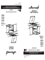 1
1
-
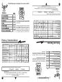 2
2
-
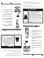 3
3
-
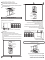 4
4
-
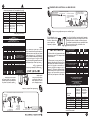 5
5
-
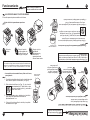 6
6
-
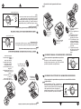 7
7
-
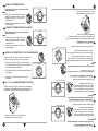 8
8
-
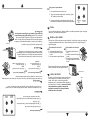 9
9
-
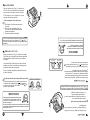 10
10
-
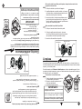 11
11
-
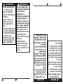 12
12
-
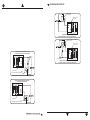 13
13
-
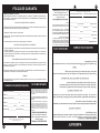 14
14
-
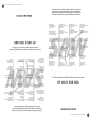 15
15
-
 16
16
-
 17
17


Acros AB20214 Guía del usuario
- Categoría
- Cocinas
- Tipo
- Guía del usuario
En otros idiomas
- English: Acros AB20214 User guide
Otros documentos
-
Maytag MF5555B Manual de usuario
-
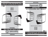 DDA SuperMatic SUPERMATIC SF11120 Manual de usuario
-
LG RSG314M El manual del propietario
-
Whirlpool AP2400S Guía del usuario
-
Samsung NX52T7322LS/AP Manual de usuario
-
-
Whirlpool AKT 305/IX Guía del usuario
-
-
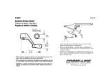 Prime-Line H 3532 Guía de instalación
-
mabe EM7630BAPN1 El manual del propietario

