DDA SuperMatic SUPERMATIC SF11120 Manual de usuario
- Tipo
- Manual de usuario

INSTRUCTIVO
DE INSTALACIÓN, USO Y MANEJO
ESTUFAS
No. Parte W10114268 Rev. Rel.
Ampara los siguientes modelos:
SF11120
SF13120
SF13420
SE13500
LEA CUIDADOSAMENTE ESTE INSTRUCTIVO ANTES
DE USAR POR PRIMERA VEZ SU ESTUFA
INSTALLATION, USE AND CARE
MANUAL
RANGES
No. Parte W10114268 Rev. Rel.
THIS MANUAL CONTAINS IMPORTANT INFORMATION,
READ IT BEFORE FIRST USE OF YOUR RANGE
Covers the following models:
SF11120
SF13120
SF13420
SE13500
Im
preso en M
éxico
STM
01526 Rev. Rel.
Printed in M
exico
STM
01526 Rev. Rel.

Acaba de adquirir un producto desarrollado
con las más avanzadas técnicas de diseño
y fabricación.
Le sugerimos que antes de usar su estufa
lea cuidadosamente las instrucciones de
este Manual, consérvelo ya que la
información contenida en el mismo será
importante para el buen funcionamiento de
su estufa durante muchos años.
Partes y Características
Instalación
Conexión
Funcionamiento
Limpieza
Póliza de Garantía
Formato de Identificación
Centros de Servicio Autorizados
2
3
4
5
8
9
9
10
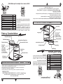
Partes y Características
¡ Felicidades por la compra de su nueva estufa !
2
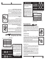
Instale su estufa en un lugar protegido de las inclemencias del tiempo y sobre una
superficie plana y resistente para soportar su peso.
No permita que la usen niños o personas que no conozcan su funcionamiento.
Proporciónele el mantenimiento adecuado.
Utilice la estufa solo en labores del hogar. No es un aparato de uso comercial.
127 V ± 10% 50/60 Hz 1,0 A Max.
Características eléctricas nominales:
Parts and Features
Installation
Gas Supply Connection
How to Use Your Range
Cleaning and Maintenance
Warranty
Identification Format
Authorized Service Centers
2
3
4
5
8
9
9
10
Parts and Features
¡ Congratulations !
2
Install your range in an area that is protected against weather exposure, on a level floor
strong enough to sustain its weight.
Do not allow range to be used by children or unqualified adults.
Provide for adequate maintenance.
Use the range only in home applications. It is not designed for commercial use.
This range was carefully manufactured with
the latest technical expertise. By purchasing
it, you have received quality; but remember,
quality requires maintenance.
Before you use your range, read the
instructions in this manual, the information
is important for best results in the use of
your range.
Electrical Characteristics:
127 V ± 10% 50/60 Hz 1,0 A Max.
Oven Thermocontrol
Surface Burners
Backguard
Top Grates
Burner Valves
Oven Rack
Oven Door
Electronic Ignition
Switch & Oven
Light Switch
(Only in model SF13420)
Cooktop
Manifold Panel
Termocontrol de Horno
Quemadores Superiores
Respaldo Superior
Parrillas Superiores
Válvulas de
Quemadores
Parrilla de
Horno
Puerta de Horno
Interruptor
Encendido
Electrónico
y Luz de Horno
(Solo en Modelo SF13420)
Cubierta Superior
Frente de
Perillas
MANUFACTURED BY:
INDUSTRIAS ACROS WHIRLPOOL, S,A, DE C.V. Unidad Celaya
km 280
CARRETERA PANAMERICANA C.P. 38020, CELAYA, GTO.
Tel. 01 (461) 618 5500
FABRICADO POR:
INDUSTRIAS ACROS WHIRLPOOL, S,A, DE C.V. Unidad Celaya
km 280
CARRETERA PANAMERICANA C.P. 38020, CELAYA, GTO.
Tel. 01 (461) 618 5500

La instalación apropiada es su responsabilidad.
Un técnico calificado o un técnico de Servicio
debe instalar esta estufa.
Retire los elementos de empaque, cartón, unicel
y cintas.
Seleccione la mejor ubicación para su estufa,
no debe quedar expuesta a corrientes de aire
y debe tener espacio suficiente para abrir la
puerta del horno.
No instale gabinetes o muebles de cocina
encima de la estufa.
Si instala campana extractora, colóquela a 61 cm
como mínimo, de la cubierta de la estufa.
Si su estufa cuenta con accesorios eléctricos,
colóquela cerca de un tomacorriente de pared.
No use extensiones eléctricas o contactos
múltiples.
61 cm
mínimo
3
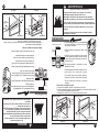
Instalación
CAMPANA EXTRACTORA
61 cm
min.
3
Installation
EXHAUST DEVICE
Proper installation is your responsibility. A
qualified technician or Service technician must
install this range.
Remove all packing parts, card board, plastic
foam and tapes.
Select the best location in your kitchen for your
range, protected from wind and with enough
space to open the oven door.
Do not install cabinetry directly above the range.
If you will install an exhaust device, put it at 61
cm minimum from the range cooktop.
If your range has a power cord, it must be
installed near an electrical wall outlet.
Do not use extension cords or multiple outlets.
Fire or Explosion Hazard
Do not allow children to use or play with the range;
keep children away while range is in use.
Keep the range surroundings free of flammable material,
gasoline and other vapors or flammable liquids.
Do not get too close to the flame produced by the
burners or wear loose clothing; your clothes may ignite
if contact by open flames.
Do not use your range to warm rooms, because this is
dangerous.
Failure to do so can result in death, fire or explosion.
WARNING
!
Peligro de Incendio y/o Quemaduras
No permita que los niños usen o jueguen con la estufa;
manténgalos alejados mientras está en uso.
Mantenga los alrededores del aparato libres de materiales
combustibles, gasolina y otros vapores o líquidos flamables.
No se acerque demasiado a las flamas de los quemadores, ni
use ropa suelta, ya que se puede encender y causar quemaduras.
No use su estufa para calentar habitaciones, ya que esto es
peligroso.
No seguir estas instrucciones puede ocasionar incendio,
quemaduras o la muerte.
ADVERTENCIA
!
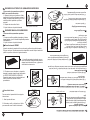
Como instalar el respaldo superior
1.-Las partes del respaldo superior se encuentran en el horno .
2.-Coloque el respaldo superior en la estufa insertándolo en el travesaño posterior,revise
con que opción de respaldo cuenta su estufa.
3.-Utilizando los tornillos A y B atornille el respaldo a la estufa.
How to Install the backguard in ranges
1.-Backguard parts are inside oven.
2.-Mount the backguard in place over the backguard support on the range, check
which backguard option is included in your range .
3.-Use the screws A and B to fix the backguard to the range.
A
B
A
A
B
A
RESPALDO SUPERIOR
TRAVESAÑO
POSTERIOR
RESPALDO SUPERIOR
TRAVESAÑO
POSTERIOR
B
B
A
A
Use un desarmador
punta Phillips
Use un desarmador
punta Phillips
TORNILLO CABEZA
ESTANDAR
TORNILLO CABEZA
CONICA
A
B
A
A
B
A
BACKGUARD BACKGUARD
B
B
A
A
Use a Phillips screwdriver
Use a Phillips screwdriver
BACKGUARD
SUPPORT
STANDARD HEAD
SCREW
CONICAL HEAD
SCREW
BACKGUARD
SUPPORT
Opción A Opción B
Option A Option B

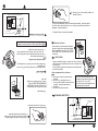
Para efectuar la conexión de la estufa, es necesario retirar completamente la
cubierta superior, para lo cual se deben realizar las siguientes operaciones:
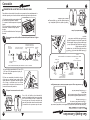
Conexión
1.-En algunos modelos es necesario quitar
los tornillos que sujetan la cubierta.
2.- Levante la cubierta superior de la parte
frontal.
3.-En los modelos con tirantes, presione
hacia atras al mismo tiempo que los
levanta.
4.- Retire la cubierta hacia el frente para
liberarla.
A) Use dos llaves españolas de 22,2 mm (7/8)
y 18,3 mm (3/4) para apretar el cople y la
tuerca de campana.
Para conectar su estufa, utilice el material especificado en la figura
de abajo.
CONEXIÓN DE LA ESTUF
A A LA LÍNEA DE GAS
B) Una vez conectado el suministro de gas,
revise que no existan fugas, puede utilizar
agua jabonosa. Coloque la cubierta superior
en su lugar, verificando que los orificios
posteriores de la misma se inserten en los
pernos del travesaño posterior.
To perform the gas supply connection, the installer must completely remove the
range top, following the instructions below.
Gas Supply Connection
1.- Remove screws that fix cook top
2.- Lift front of cooktop.
3.- In some models,push the support rods
away from the range at the same time you
are raising.
4.- Pull cooktop forward and out.
A) Use two open end wrench of 7/8 and 3/4
to connect the flared type nut, hex, adapter
and gas intel tube fitting.
GAS SUPPLY CONNECTION
B) After connecting the gas supply, check
with soap solution for leaks, replace range
top making sure the rear holes are properly
lined up with the hinge pins on the back
support.
1
1
CUBIERTA SUPERIO
R
2
CO
O
KTO
P
Coloque los accesorios en la estufa
2
Tubo de
alim
entación
de la estufa
4
4
To connect the range, use the material shown in the bottom figure.
NOTE: The m
aterial shown for installation is not provided with the
range.
3/8" shut off
valve
G
as
regulator
3/8" copper pipe with
5/8" flared type nut.
Necessary
length to reach the
gas
3/8" brass pipe
fitting
Hex. adapter
3/8" copper pipe
with 5/8" flared
type nut
3/8" brass pipe fitting hex.
adapter
NOTA: El m
aterial m
ostrado para instalacion no viene con la estufa.
Llave de paso
de 9,5 m
m
(3/8")
Tubo de cobre con tuercas
cónicas de 9,5 m
m
(3/8") de
longitud necesaria para llegar
al gas
Cople-Niple de
9,5 m
m
(3/8"NPT)
Regulador
de gas
Tubo de cobre con tuercas
cónicas de 9,5 m
m
(3/8")
Cople-Niple de 9,5 m
m
(3/8" NPT)
Set accesories in place.
To make it easier to move the appliance, the
installer should loop the 3/8" copper tubing as
shown in the illustration.
Con el fin de facilitar el movimiento del
aparato, el instalador debe hacer una espiral
con el tubo flexible de cobre e instalar una
llave de paso en la línea de suministro de
gas, esta llave debe estar fuera de la estufa
y accesible a las personas que la usan.

NOTA: Para operar esta estufa con gas natural,
se requiere el juego de conversión de acuerdo
con la siguiente tabla:
No. de juego
Modelo de estufa de conversión
5
IMPORTANTE
GAS LP PRESIÓN DE OPERACIÓN
2,75 kPa (28 cm Col. agua)
Esta estufa está preparada para
funcionar con gas L.P. de tanque
móvil o estacionario.
Para usarse con gas natural ( de
tubería) debe llamar a Servicio Acros
Whirlpool para cambiar las espreas
y hacer los ajustes necesarios, el
número telefónico aparece en la
última página. El técnico calificado
debe cerciorarse que la conexión
no tiene fugas y que la presión de
gas en la estufa es la que aparece
en las tablas.
QUEMADOR
SUPERIOR
HORNO
ESPREA
69
62
mm
0,741
0,965
kJ/h
6 500
10 000
DIAM.
ESPREA
CAPACIDAD
TERMICA
QUEMADOR
SUPERIOR
HORNO
ESPREA
56
53
mm
1,181
1,511
kJ/h
6 500
10 000
DIAM.
ESPREA
CAPACIDAD
TERMICA
GAS NATURAL PRESIÓN DE OPERACIÓN
1,76 kPa (18 cm Col. agua)
5
IMPORTANT
NOTE: To operate this range with natural gas, is
required a kit according to the chart:
This kit is available at your nearest Authorized
Service Center.
Range Model Kit Number
This range is adjusted at the factory
for use with L.P. gas.
To use this range with natural gas,
you must replace the surface and
oven burner orifices, call Servicio
Acros-Whirlpool, the phone number
is shown in the last page. The
technician must make sure that the
connections have no leaks and the
gas pressure in the range is the
same as shown in the charts.
LP GAS OPERATING PRESSURE
11 in WATER COLUMN
(6,36 oz/squared inch)
BURNER
UPPER
OVEN
NUMBER
69
62
INCHES
0,741
0,965
BTU/h
6 500
10 000
ORIFICE
DIAMETER
THERMAL
CAPACITY
ORIFICE
NATURAL GAS OPERATING
PRESSURE 7 in WATER COLUMN
(4,04 oz/squared inch)
BURNER
UPPER
OVEN
NUMBER
56
53
INCHES
1,181
1,511
BTU/h
6 500
10 000
ORIFICE
DIAMETER
THERMAL
CAPACITY
ORIFICE
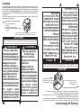
Funcionamiento
Las diferentes altitudes sobre el nivel del mar y las variaciones en
el suministro de gas, hacen necesario regular la entrada de aire
primario a los quemadores para obtener una adecuada mezcla de
aire-gas y así tener un buen funcionamiento en la estufa.
Revise que las flamas de los quemadores superiores y el horno
sean estables y azuladas, de no ser así siga los siguientes pasos
para su ajuste.
AJUSTES DE FLAMAS
Quemadores superiores
1.- Retire la cubierta como se indica en la página 4
2.- Para ajustar el aire, afloje el tornillo del regulador de aire y
desplácelo hacia delante o hacia atrás (si la flama es amarilla,
desplácelo ligeramente hacia atrás; si la flama es inestable y separada
del quemador, desplácelo hacia delante)
3.- Coloque la cubierta y quemadores en su lugar y revise que la
flama sea azulada y estable, de lo contrario espere a que el quemador
se enfrié y repita todos los pasos hasta obtener una flama adecuada
Quemador de horno
1.- Retire primero la charola del horno (ver página 8) y posteriormente
quite el tornillo que sujeta al quemador del horno al bastidor frontal,
retire el quemador.
2.- Para ajustar el aire afloje el tornillo del regulador de aire y gire
el regulador para abrir o cerrar la ventana (si la flama es amarilla,
abra ligeramente la ventana; si la flama es inestable y separada del
quemador, cierre ligeramente la ventana).
3.- Coloque el quemador en su lugar sujetándolo con el tornillo y
revise que la flama sea azulada y estable, de lo contrario espere a
que el quemador se enfrié y repita todos los pasos hasta obtener
una flama adecuada.
REGULADOR
DE AIRE
Quemador Superior
TORNILLO
REGULADOR
Quemador de Horno.
How to Use Your Range
Because of different altitudes above sea level and variations
in the supply of gas, you may need to adjust the main air
intake to the burners. This will result in a better air-gas mixture
and thus of better operation.
Check surface burners and oven burner for proper flame,
flame must be steady and blue, if not follow below instructions
for flame adjustment.
Surface Burners
1. - Remove cooktop as shown on page 4.
2.- Adjust air by loosing air shutter screw, move air shutter
forward or backwards (if flame is yellow, move air shutter
forward; if flame is blowing, move air shutter backwards).
3. - Replace cooktop and surface burners, check burner for
proper flame, if the flame is still not properly adjusted, wait
for the burner to cool down and repeat steps 1 and 2 until
flame is properly adjusted.
Oven Burner
1. - Remove oven tray (see page 8), remove screw on front
frame and then remove oven burner from range.
2.- Adjust air by loosing air shutter screw and turn air shutter
to open or close opening (if flame is yellow, open burner
opening; if flame is blowing, close opening)
3. - Replace oven burner and tighten shutter screw, check
burner for proper flame, if the flame is still not properly
adjusted, wait for the burner to cool down and repeat steps
1 and 2 until flame is properly adjusted.
AIR
SHUTTER
Top Burner
AIR
SHUTTER
SCREW
Oven Burner
Este juego está disponible con su Centro de
Servicio Autorizado.
SF11120
SF13120
SF13420
SE13500
98016197
98016197
98016197
98016197
SF11120
SF13120
SF13420
SE13500
98016197
98016197
98016197
98016197

6
6
HOW TO TURN ON OVEN BURNERS MANUALLY
To turn on the oven burner manually:
1.- Light a match and place it close the burner while you
push and turn the knob 1/4 of the way to the maximum
flame position .
2.-Set the knob to your desired heat level.
To turn on the surface burner with
electronic ignition:
1.-Push the button located on the left side of
the manifold panel to light the electronic ignition
while you push and turn the desired knob.
2.-Release the ignition button when the burner
lights.
3.-Set knob to your desire heat level.
SURFACE BURNERS WITH ELECTRONIC IGNITION
Knob in ignition position.
How to use the oven.
1.- Before using the oven, place the rack in the desired position. The oven has three
rack positions so that the oven rack can be raised or lowered according to the type and
size of the cooking utensils
You must place the rack so that the curved end
of the rack is towards the back wall of the oven.
The straight end will be towards the door.
2.- To change the rack position, pull the rack until
it stops. Insert the rack in the oven, place the
curved end of the desired rack guides, raising the
front part of the rack.
The rack should be positioned so that the food is
centered in the oven. Always leave a clearance of
4-5 cm (1-1/2 to 2) betwen the pan and the oven
wall or other pans.
OFF
MINIMUM
FLAME
MAXIMUM
FLAME
OFF
MINIMUM
FLAME
MAXIMUM
FLAME
ELECTRONIC IGNITION
& OVEN LIGHT
BUTTON
Para encender los quemadores superiores:
1.- Acerque un cerillo encendido al quemador y al mismo
tiempo presione y gire 1/4 de vuelta la perilla del quemador
correspondiente.
2.- Ajuste la flama en la posición deseada
ENCENDIDO MANUAL DE QUEMADORES
Para encender los quemadores superiores
con encendido electrónico
1.- Oprima el botón que se localiza en el lado
izquierdo del frente de perillas para accionar la
chispa y al mismo tiempo presione y gire 1/4 de
vuelta la perilla del quemador que desea
encender.
2.- Despues de esto suelte el botón.
3.- Ajuste la flama en la posición deseada
ENCENDIDO ELECTRÓNICO DE QUEMADORES SUPERIORES
Perilla en posición de encendido.
Como funciona el HORNO.
Antes de encender el quemador del horno colocar la parrilla en la posición deseada.
El horno cuenta con 3 posiciones para ubicar la parrilla de acuerdo al tipo o tamaño del
platillo. La parrilla se coloca de la siguiente manera:
1.- La parrilla presenta un terminado curvo en
uno de los extremos. Esta parte debe colocarse
siempre hacia el interior del horno, y dejar como
vista frontal el extremo recto.
2.- El extremo curvo se introduce en la posición
deseada, levantando la parte frontal donde están
los TOPES DE SEGURIDAD LATERALES.
Después de pasar los topes, deslizarla hacia el
interior. Para retirar, efectuar el mismo
procedimiento.
APAGADO
FLAMA
MÍNIMA
FLAMA
MÁXIMA
BOTÓN DE ENC.
ELECTRÓNICO
Y LUZ DE HORNO
APAGADO
FLAMA
MÍNIMA
FLAMA
MÁXIMA
How to light the Oven.
Oven burner manual lighting:
1.- Open the oven door.
2.- Light a match and place the flame at the ignition
hole in the front center of the oven tray.
3.- Push in and turn the oven valve knob 1/4 of the
way, and the burner will light immediately
Encendido del horno.
Para encender el quemador del horno siga las
instrucciones:
1.- Abra la puerta del horno.
2.-Encienda un cerillo y colóquelo en el orificio
para encendido como lo indica la ilustración

3.- Oprima y gire 1/4 de vuelta la perilla de la
válvula de horno.
4.-Revise inmediatamente que el quemador haya encendido, asómese a través
del orificio de la charola del horno, si no es asi, gire la perilla a la posición de
apagado, y repita la operación.
5.-Ajuste la flama en la posición deseada.
Ventilación del horno
El aire caliente y la humedad son liberados
del horno a través de una abertura localizada
bajo el respaldo de la estufa. NO CUBRA
ESTA ABERTURA. Puede resultar en mal
cocimiento.
DIAGRAMA ELÉCTRICO
Foco de Horno 40 W.
Diagrama Eléctrico Estufa con Luz en el Horno y
Encendido Electrónico con Interruptor Independiente.
Módulo de Encendido
4, 6 u 8 salidas.
Interruptor Luz de Horno e Interruptor Módulo de
Encendido Integrados
N
L1
4.-Check if the oven burner is lighting looking
through the hole in the oven tray. if not, turn knob
to off position and repeat the operation.
5.-Set knb to your desired heat level .
The oven vent
Hot air and moisture are released from
oven through an opening located below
the backguard of the range. DO NOT
COVER THIS OPENNING. Poor baking
can result.
OVEN EXHAUST VENT
ELECTRICAL DIAGRAM
Electrical Diagram Range with Oven Light and
Electronic Ignition with Independent Switch.
Oven Bulb 40 W
Ignition Module.
Integrated Oven Light Switch & Electronic Ignition
Switch
N
L1
VENTILACIÓN DEL HORNO
7
7
LUZ DE HORNO
Algunos modelos(ver pag.2), cuentan con luz en el horno,
la iluminación es importante para revisar el horneado sin
abrir la puerta.
La luz enciende al operar el interruptor en el lado izquierdo
del frente de perillas.
NOTA: El cable tomacorriente debe
conectarse a una toma de corriente con
un voltaje de 127 V
± 10%.
Cerciórese de que la instalación esté
apropiadamente aterrizada.
Para reemplazar el foco del horno:
1.- Desconecte el cable tomacorriente de
la estufa.
2.- Retire el foco y reemplácelo con un
foco nuevo de 40 watts de la misma forma
y tamaño, especial para aparatos
domésticos.
3.- Conecte la estufa nuevamente.
OVEN LIGHT
Some range has an oven light (See pag. 2).To turn on the
oven light push
the switch located on the left side of the manifold panel .
How to replace the oven bulb:
1.- Disconnect the power cord.
2.- Remove the bulb and replace with a new 40 watts, with
the same size and shape, special appliance bulb.
3.- Connect the power cord again.
NOTE: Connect the range in a wall outlet with a voltage of
127 V ± 10%. Be sure the installation is properly grounded.

8
Cleaning and Maintenance
Unplug range from current.Regularly clean grates, burners, cooktop and the oven tray, use
water, soap and a damp cloth, avoid using abrasive or sharp objects. Periodically clean
the gap between the cooktop and the manifold panel.
Your range has the Continuous Cleaning System in the oven, it is not necessary to clean
the walls of the oven, the spills will burn each time you bake.
You can use aluminum foil to wrap the oven tray, avoid covering the side grooves.
Do not use caustic soda or cleaning agents which contain it to clean the range.
Failure on following the above, will permanently damage the surfaces where it is applied.
IMPORTANT
How to remove the oven tray:
1.- Turn front clips.
2.- Lift front of tray.
3.- Lift rear of tray and remove it.
You can use aluminum
foil to wrap the oven tray,
avoid covering the side
grooves.
8
Limpieza
Desconecte el cable toma corriente de la estufa, si su estufa cuenta con este. Es necesaria la
limpieza periódica de la estufa, use agua, jabón y un trapo húmedo, no use fibra metálica, porque
se ralla el esmalte. Limpie regularmente el hueco entre la cubierta superior y el frente de perillas.
Su estufa cuenta con el Sistema de Autolimpieza en el horno (acabado rugoso), no es necesario que
limpie las paredes, ya que con cada horneado se van quemando los residuos de alimentos que se
van salpicando.
Puede usarse papel aluminio para forrar la charola del horno, teniendo cuidado de NO
tapar las ranuras de la misma.
No utilice sosa cáustica o productos de limpieza que la contengan para limpiar la estufa.
De no seguir esta instrucción se ocasionarán daños permanentes en las superficies donde se aplique.
IMPORTANTE
Como retirar la charola del horno:
1.- Gire los dos sujetadores
frontales
2.- Levante la charola del frente
3.- Despues levantela de la parte trasera
y retirela.
Puede usar papel aluminio para forrar la charola del horno,
teniendo cuidado de NO tapar las ranuras de la misma.
Para su seguridad:
No almacene gasolina u
otros fluidos flamables en
la cercanía de su aparato.
Asegúrese que los
muebles cercanos a
su estufa, así como el
muro y piso soporten
una temperatura de
180
o
C, para que no
sufran deformaciones.
No obstruya las ranuras
de la charola del horno.
No seguir estas
instrucciones puede
ocasionar riesgo de fuego
o explosión o la muerte.
Para su seguridad:
Si huele a gas
Abra las ventanas.
No toque interruptores
eléctricos.
Apague todas las
flamas cerrando la
válvula general de paso.
Llame inmediatamente
a la central de fugas o
a su proveedor de gas.
No seguir estas
instrucciones puede
ocasionar riesgo de
fuego o explosión.
ADVERTENCIA
!
ADVERTENCIA
!
For your safety
Do not store gasoline
or other flamable liquids
near to your range.
Make sure that the
furniture near to your
range, as well as the
wall and the floor must
support a temperature
of 180
o
C to avoid any
deformation.
Do not obstruct the side
grooves in the oven tray.
Failure to follow the
above precautions
may result in death,
fire or explosion.
For your safety
IF YOU SMELL GAS:
Open the windows.
Do not activate any
light switch.
Close the gas line supply
and the connection shut
off valve.
I
mmediately call your
authorized repair service
or your gas supplier.
Failure to follow the
above precautions
may result in fire or
explosion.
WARNING
!
WARNING
!

9
9
Este documento deberá ser presentado para cualquier
trámite relacionado con la garantía de productos
adquiridos dentro de la República Mexicana, si usted
compró su producto en otro país, acuda a la casa
comercial/ distribuidor donde fué adquirido.
EL COMPRADOR DEBERÁ MANTENER ESTE
DOCUMENTO EN SU PODER Y EN UN LUGAR
SEGURO.
El consumidor podrá solicitar que se haga efectiva la
garantía que ampara esta póliza, ante la casa comercial
donde se adquirió el producto. En caso de extravío de
la póliza mencionada, el proveedor expedirá una nueva
póliza de garantía, previa presentación de la nota de
compra o factura respectiva.
WHIRLPOOL SERVICE
Dentro de la República Mexicana
Utilice sin cargo para usted el Servicio
Nacional Clientes
Teléfono 01-800-83-004-00
FORMATO DE IDENTIFICACIÓN
N
OMBRE DEL COMPRADOR ______________________________________
DOMICILIO_________________________ TEL. ______________________
NOMBRE DEL DISTRIBUIDOR _____________________________________
DOMICILIO __________________________ TEL. ______________________
PRODUCTO______________ MARCA_________ MODELO_____________
NUM. DE SERIE ________________FECHA DE ENTREGA_______________
FIRMA DEL DISTRIBUIDOR Y SELLO REPRESENTANTE AUTORIZADO
(Señale con precisión calle, número exterior o interior;
colonia, ciudad, estado y C.P.)
NOTA IMPORTANTE
WHIRLPOOL MEXICO, S.A. DE C.V.
Antigua Carretera a Roma km 9, Col. Milagro, Apodaca, N.L., México, C.P. 66600, Tel. (81)83-29-21-00,
en los términos de esta póliza, garantiza al comprador de la estufa identific
ada en la presente póliza,
AMPARA LOS SIGUIENTES MODELOS:
SF11120, SF13120, SF13420, SE13500
CONCEPTOS CUBIERTOS POR LA GARANTÍA:
Defectos de fabricación que impidan total o parcialmente el correcto funcionamiento de la estufa, que
se presenten dentro del término de vigencia de esta garantía.
Reparación, cambio de piezas y componentes.
Mano de obra y gastos de transportación derivados del cumplimiento de la garantía, dentro de nuestra
red de servicio.
Los puntos anteriores se harán sin costo alguno para el Consumidor.
CONCEPTOS NO CUBIERTOS POR LA GARANTÍA:
- Cuando el producto ha sido utilizado en condiciones distintas a las normales (la estufa no es para uso
comercial o industrial).
- Cuando el producto no ha sido operado de acuerdo con el instructivo de instalación y uso de la estufa.
- Cuando el producto ha sido alterado o reparado por personas o establecimientos no autorizados por
Whirlpool Service.
PROCEDIMIENTO PARA HACER EFECTIVA LA GARANTÍA:
Al considerar el comprador final que ha ocurrido algún evento amparado por esta póliza, deberá
ponerse en contacto con Whirlpool Service a nuestro Centro Nacional de Llamadas, desde
Monterrey N.L y su área conurbada al (81) 83-29-2100 y desde el interior de la República
Mexicana al 01-800-8-300-400; donde un asesor de servicio especializado lo atenderá. Nuestras
instalaciones están ubicadas en Carretera Miguel Alemán Km. 16 Col. El Milagro C.P 66600.
Apodaca, N.L. En donde también podrá encontrar accesorios y partes originales. Para mayor
información de nuestros servicios, visite www.whirlpoolservice.com.mx."
Esta garantía quedará sin efecto cuando personas o establecimientos no autorizados intervengan en
la reparación o reemplazo de componentes de fabricación.
TÉRMINO:
Esta garantía tiene una vigencia de UN AÑO a partir de la fecha en que el consumidor reciba de
conformidad la estufa.
PÓLIZA DE GARANTÍA
This document must be shown in any
transaction related with this warranty for
products acquired in the Mexican Republic.
If you bought your range out of the Mexican
Republic, ask your authorized dealer to
make valid your warranty.
THE CONSUMER CAN REQUEST THE
WARRANTY COVERED BY THIS POLICY
FROM THE DEALER WHERE THE
PRODUCT WAS PURCHASED.
In case of loss of policy, the dealer will issue
a new one, with the proper bill of sale or
invoice.
WHIRLPOOL SERVICE
Call free in Mexico
Use without charge the Nationwide
Consumer Assistance Center
Phone number 01-800-83-004-00
IDENTIFICATION FORMAT
CONSUMER NAME
_____________________________________________
ADDRESS________________________ PHONE ______________________
DEALER NAME__________________________________________________
ADDRESS ________________________ PHONE
______________________
PRODUCT___________TRADEMARK______________ MODEL __________
SERIAL NUMBER ________________DELIVERY DATE__________________
DEALER SIGNATURE AND STAMP AUTHORIZED REPRESENTATIVE
(Indicate precise steet, col. state and zip code).
IMPORTANT NOTE
WARRANTY
WHIRLPOOL MEXICO, S.A. DE C.V.
Antigua Carretera a Roma km 9, Col. Milagro, Apodaca, N.L., Mexico, C.P. 66600,
phone (81)83-29-21-00, in the terms of this policy, we warranty to the buyer and the consumer of this
range identified in this following policy:
PROTECT THE FOLLOWINGS MODELS:
SF11120, SF13120, SF13420, SE13500
COVERED CONCEPTS:
Manufacturing defects that hinder total or partially the correct performance of the appliance. Repair,
change of pieces and components.
Handwork and transportation expenses derived from the fulfillment of the warranty, within our service
net. The previous points will be made without any cost for the consumer.
NOT COVERED CONCEPTS:
- When the range is used in other than normal, single family household use.
- When the range is not used according to the use and care guide attached.
- When the range has been repaired by unauthorized service.
PROCEDURE TO MAKE EFFECTIVE THE WARRANTY:
When the final customer considers one of the events protected by this contract has happened,
he/she will have to make contact with Whirlpool Service through our Call Center, in Monterrey, N.L
and its surrounding area to (81) 83-29-2100; or from the interior of the Mexican Republic to 01-
800-8-300-400:where a specialized service agent will take care of the matter. Our facilities are
located in Miguel Alemán Highway km 16 Col. El Milagro C.P 66600. Apodaca, N.L. where Whirlpool
original parts and accessories can also be found. For additional information of our services, visit
www.whirlpool-service.com.mx.
TERMS:
This warranty covers ONE YEAR beginning the day the buyer or consumer receives the range to his
satisfaction.
La página se está cargando ...
La página se está cargando ...
La página se está cargando ...
Transcripción de documentos
No. Parte W10114268 Rev. Rel. ESTUFAS Printed in Mexico STM01526 Rev. Rel. THIS MANUAL CONTAINS IMPORTANT INFORMATION, READ IT BEFORE FIRST USE OF YOUR RANGE INSTRUCTIVO DE INSTALACIÓN, USO Y MANEJO SF11120 SF13120 SF13420 SE13500 Covers the following models: Ampara los siguientes modelos: SF11120 SF13120 SF13420 SE13500 MANUAL INSTALLATION, USE AND CARE LEA CUIDADOSAMENTE ESTE INSTRUCTIVO ANTES DE USAR POR PRIMERA VEZ SU ESTUFA Impreso en México STM01526 Rev. Rel. No. Parte W10114268 Rev. Rel. RANGES ¡ Felicidades por la compra de su nueva estufa ! 2 MANUFACTURED BY: INDUSTRIAS ACROS WHIRLPOOL, S,A, DE C.V. Unidad Celaya km 280 CARRETERA PANAMERICANA C.P. 38020, CELAYA, GTO. Tel. 01 (461) 618 5500 9 Formato de Identificación 9 Centros de Servicio Autorizados 10 Le sugerimos que antes de usar su estufa lea cuidadosamente las instrucciones de este Manual, consérvelo ya que la información contenida en el mismo será importante para el buen funcionamiento de su estufa durante muchos años. Oven Door Póliza de Garantía Partes y Características Electronic Ignition Switch & Oven Light Switch 8 (Only in model SF13420) Limpieza Acaba de adquirir un producto desarrollado con las más avanzadas técnicas de diseño y fabricación. Burner Valves 5 Oven Rack Funcionamiento 1,0 A Max. 4 50/60 Hz 3 Conexión ± 10% Instalación Electrical Characteristics: 127 V 2 Install your range in an area that is protected against weather exposure, on a level floor strong enough to sustain its weight. Do not allow range to be used by children or unqualified adults. Provide for adequate maintenance. Use the range only in home applications. It is not designed for commercial use. Partes y Características Respaldo Superior Quemadores Superiores Surface Burners Backguard Parrilla de Horno Parts and Features 8 5 How to Use Your Range 4 Gas Supply Connection 3 Installation 2 Parts and Features This range was carefully manufactured with the latest technical expertise. By purchasing it, you have received quality; but remember, quality requires maintenance. ¡ Congratulations ! FABRICADO POR: INDUSTRIAS ACROS WHIRLPOOL, S,A, DE C.V. Unidad Celaya km 280 CARRETERA PANAMERICANA C.P. 38020, CELAYA, GTO. Tel. 01 (461) 618 5500 Cleaning and Maintenance Instale su estufa en un lugar protegido de las inclemencias del tiempo y sobre una superficie plana y resistente para soportar su peso. No permita que la usen niños o personas que no conozcan su funcionamiento. Proporciónele el mantenimiento adecuado. Utilice la estufa solo en labores del hogar. No es un aparato de uso comercial. 9 1,0 A Max. 9 50/60 Hz Warranty ± 10% Identification Format Before you use your range, read the instructions in this manual, the information is important for best results in the use of your range. Válvulas de Quemadores 10 Puerta de Horno (Solo en Modelo SF13420) Authorized Service Centers Interruptor Encendido Electrónico y Luz de Horno Top Grates Frente de Perillas 2 Oven Thermocontrol Termocontrol de Horno Cooktop Cubierta Superior Características eléctricas nominales: 127 V Manifold Panel Parrillas Superiores ! ADVERTENCIA 3 Peligro de Incendio y/o Quemaduras Option A No permita que los niños usen o jueguen con la estufa; manténgalos alejados mientras está en uso. Option B Use a Phillips screwdriver BACKGUARD SUPPORT Mantenga los alrededores del aparato libres de materiales combustibles, gasolina y otros vapores o líquidos flamables. CONICAL HEAD SCREW B Use a Phillips screwdriver A B No se acerque demasiado a las flamas de los quemadores, ni use ropa suelta, ya que se puede encender y causar quemaduras. STANDARD HEAD SCREW B A No use su estufa para calentar habitaciones, ya que esto es peligroso. BACKGUARD SUPPORT B A No seguir estas instrucciones puede ocasionar incendio, quemaduras o la muerte. A A A Instalación BACKGUARD BACKGUARD 1.-Backguard parts are inside oven. 2.-Mount the backguard in place over the backguard support on the range, check which backguard option is included in your range . 3.-Use the screws A and B to fix the backguard to the range. CAMPANA EXTRACTORA La instalación apropiada es su responsabilidad. Un técnico calificado o un técnico de Servicio debe instalar esta estufa. Retire los elementos de empaque, cartón, unicel y cintas. How to Install the backguard in ranges 61 cm mínimo Do not use extension cords or multiple outlets. Seleccione la mejor ubicación para su estufa, no debe quedar expuesta a corrientes de aire y debe tener espacio suficiente para abrir la puerta del horno. If your range has a power cord, it must be installed near an electrical wall outlet. If you will install an exhaust device, put it at 61 cm minimum from the range cooktop. No instale gabinetes o muebles de cocina encima de la estufa. Do not install cabinetry directly above the range. Si instala campana extractora, colóquela a 61 cm como mínimo, de la cubierta de la estufa. Select the best location in your kitchen for your range, protected from wind and with enough space to open the oven door. Si su estufa cuenta con accesorios eléctricos, colóquela cerca de un tomacorriente de pared. Remove all packing parts, card board, plastic foam and tapes. No use extensiones eléctricas o contactos múltiples. Como instalar el respaldo superior 1.-Las partes del respaldo superior se encuentran en el horno . 2.-Coloque el respaldo superior en la estufa insertándolo en el travesaño posterior,revise con que opción de respaldo cuenta su estufa. 3.-Utilizando los tornillos A y B atornille el respaldo a la estufa. RESPALDO SUPERIOR RESPALDO SUPERIOR A A A A B TRAVESAÑO POSTERIOR A B B TORNILLO CABEZA ESTANDAR A TORNILLO CABEZA CONICA TRAVESAÑO POSTERIOR Use un desarmador punta Phillips Opción A B Use un desarmador punta Phillips Opción B 3 61 cm min. EXHAUST DEVICE Proper installation is your responsibility. A qualified technician or Service technician must install this range. Installation Fire or Explosion Hazard Do not allow children to use or play with the range; keep children away while range is in use. Keep the range surroundings free of flammable material, gasoline and other vapors or flammable liquids. Do not get too close to the flame produced by the burners or wear loose clothing; your clothes may ignite if contact by open flames. Do not use your range to warm rooms, because this is dangerous. Failure to do so can result in death, fire or explosion. ! WARNING Conexión 4 CONEXIÓN DE LA ESTUFA A LA LÍNEA DE GAS Para efectuar la conexión de la estufa, es necesario retirar completamente la cubierta superior, para lo cual se deben realizar las siguientes operaciones: Set accesories in place. A) Use two open end wrench of 7/8 and 3/4 to connect the flared type nut, hex, adapter and gas intel tube fitting. B) After connecting the gas supply, check with soap solution for leaks, replace range top making sure the rear holes are properly lined up with the hinge pins on the back support. Para conectar su estufa, utilice el material especificado en la figura de abajo. Tubo de alimentación de la estufa Tubo de cobre con tuercas cónicas de 9,5 mm (3/8") Tubo de cobre con tuercas cónicas de 9,5 mm (3/8") de longitud necesaria para llegar al gas 2 1 To make it easier to move the appliance, the installer should loop the 3/8" copper tubing as shown in the illustration. CUBIERTA SUPERIOR 1.-En algunos modelos es necesario quitar los tornillos que sujetan la cubierta. 2.- Levante la cubierta superior de la parte frontal. 3.-En los modelos con tirantes, presione hacia atras al mismo tiempo que los levanta. 4.- Retire la cubierta hacia el frente para liberarla. Regulador de gas Llave de paso de 9,5 mm (3/8") NOTE: The material shown for installation is not provided with the range. 3/8" brass pipe fitting hex. adapter 3/8" brass pipe fitting Hex. adapter Cople-Niple de 9,5 mm (3/8"NPT) Cople-Niple de 9,5 mm (3/8" NPT) NOTA: El material mostrado para instalacion no viene con la estufa. 1 Gas regulator To connect the range, use the material shown in the bottom figure. 3.- In some models,push the support rods away from the range at the same time you are raising. 4.- Pull cooktop forward and out. To perform the gas supply connection, the installer must completely remove the range top, following the instructions below. COOKTOP 1.- Remove screws that fix cook top 2.- Lift front of cooktop. Con el fin de facilitar el movimiento del aparato, el instalador debe hacer una espiral con el tubo flexible de cobre e instalar una llave de paso en la línea de suministro de gas, esta llave debe estar fuera de la estufa y accesible a las personas que la usan. 3/8" copper pipe with 5/8" flared type nut. Necessary length to reach the gas 2 Coloque los accesorios en la estufa 3/8" copper pipe with 5/8" flared type nut B) Una vez conectado el suministro de gas, revise que no existan fugas, puede utilizar agua jabonosa. Coloque la cubierta superior en su lugar, verificando que los orificios posteriores de la misma se inserten en los pernos del travesaño posterior. 3/8" shut off valve A) Use dos llaves españolas de 22,2 mm (7/8) y 18,3 mm (3/4) para apretar el cople y la tuerca de campana. GAS SUPPLY CONNECTION Gas Supply Connection 4 I M P O R TA N T E 5 Esta estufa está preparada para funcionar con gas L.P. de tanque móvil o estacionario. Para usarse con gas natural ( de tubería) debe llamar a Servicio Acros Whirlpool para cambiar las espreas y hacer los ajustes necesarios, el número telefónico aparece en la última página. El técnico calificado debe cerciorarse que la conexión no tiene fugas y que la presión de gas en la estufa es la que aparece en las tablas. GAS LP PRESIÓN DE OPERACIÓN 2,75 kPa (28 cm Col. agua) QUEMADOR SUPERIOR HORNO DIAM. ESPREA ESPREA 69 62 GAS NATURAL PRESIÓN DE OPERACIÓN 1,76 kPa (18 cm Col. agua) QUEMADOR SUPERIOR HORNO ESPREA 56 53 mm 0,741 0,965 DIAM. ESPREA mm 1,181 1,511 CAPACIDAD TERMICA kJ/h 6 500 10 000 CAPACIDAD TERMICA kJ/h 6 500 10 000 NOTA: Para operar esta estufa con gas natural, se requiere el juego de conversión de acuerdo con la siguiente tabla: No. de juego Modelo de estufa de conversión SF11120 SF13120 SF13420 SE13500 98016197 98016197 98016197 98016197 Este juego está disponible con su Centro de Servicio Autorizado. Funcionamiento Las diferentes altitudes sobre el nivel del mar y las variaciones en el suministro de gas, hacen necesario regular la entrada de aire primario a los quemadores para obtener una adecuada mezcla de aire-gas y así tener un buen funcionamiento en la estufa. Revise que las flamas de los quemadores superiores y el horno sean estables y azuladas, de no ser así siga los siguientes pasos para su ajuste. REGULADOR DE AIRE AJUSTES DE FLAMAS Quemadores superiores 1.- Retire la cubierta como se indica en la página 4 2.- Para ajustar el aire, afloje el tornillo del regulador de aire y desplácelo hacia delante o hacia atrás (si la flama es amarilla, desplácelo ligeramente hacia atrás; si la flama es inestable y separada del quemador, desplácelo hacia delante) 3.- Coloque la cubierta y quemadores en su lugar y revise que la flama sea azulada y estable, de lo contrario espere a que el quemador se enfrié y repita todos los pasos hasta obtener una flama adecuada Quemador de horno Quemador Superior TORNILLO REGULADOR Quemador de Horno. 1.- Retire primero la charola del horno (ver página 8) y posteriormente quite el tornillo que sujeta al quemador del horno al bastidor frontal, retire el quemador. 2.- Para ajustar el aire afloje el tornillo del regulador de aire y gire el regulador para abrir o cerrar la ventana (si la flama es amarilla, abra ligeramente la ventana; si la flama es inestable y separada del quemador, cierre ligeramente la ventana). 3.- Coloque el quemador en su lugar sujetándolo con el tornillo y revise que la flama sea azulada y estable, de lo contrario espere a que el quemador se enfrié y repita todos los pasos hasta obtener una flama adecuada. 5 Oven Burner 1. - Remove oven tray (see page 8), remove screw on front frame and then remove oven burner from range. 2.- Adjust air by loosing air shutter screw and turn air shutter to open or close opening (if flame is yellow, open burner opening; if flame is blowing, close opening) 3. - Replace oven burner and tighten shutter screw, check burner for proper flame, if the flame is still not properly adjusted, wait for the burner to cool down and repeat steps 1 and 2 until flame is properly adjusted. Oven Burner SCREW Surface Burners 1. - Remove cooktop as shown on page 4. 2.- Adjust air by loosing air shutter screw, move air shutter forward or backwards (if flame is yellow, move air shutter forward; if flame is blowing, move air shutter backwards). 3. - Replace cooktop and surface burners, check burner for proper flame, if the flame is still not properly adjusted, wait for the burner to cool down and repeat steps 1 and 2 until flame is properly adjusted. Because of different altitudes above sea level and variations in the supply of gas, you may need to adjust the main air intake to the burners. This will result in a better air-gas mixture and thus of better operation. Check surface burners and oven burner for proper flame, flame must be steady and blue, if not follow below instructions for flame adjustment. AIR SHUTTER Top Burner AIR SHUTTER How to Use Your Range This kit is available at your nearest Authorized Service Center. SF11120 SF13120 SF13420 SE13500 To use this range with natural gas, you must replace the surface and oven burner orifices, call Servicio Acros-Whirlpool, the phone number is shown in the last page. The technician must make sure that the connections have no leaks and the gas pressure in the range is the same as shown in the charts. This range is adjusted at the factory for use with L.P. gas. I M P O R TA N T Range Model 98016197 98016197 98016197 98016197 Kit Number NOTE: To operate this range with natural gas, is required a kit according to the chart: NATURAL GAS OPERATING PRESSURE 7 in WATER COLUMN (4,04 oz/squared inch) BURNER UPPER OVEN LP GAS OPERATING PRESSURE 11 in WATER COLUMN (6,36 oz/squared inch) BURNER UPPER OVEN BTU/h 6 500 10 000 INCHES 1,181 1,511 NUMBER 56 53 THERMAL CAPACITY ORIFICE DIAMETER ORIFICE BTU/h 6 500 10 000 INCHES 0,741 0,965 NUMBER 69 62 THERMAL CAPACITY ORIFICE DIAMETER ORIFICE 6 SURFACE BURNERS WITH ELECTRONIC IGNITION To turn on the surface burner with electronic ignition: 1.-Push the button located on the left side of the manifold panel to light the electronic ignition while you push and turn the desired knob. 2.-Release the ignition button when the burner lights. 3.-Set knob to your desire heat level. OFF MINIMUM FLAME MAXIMUM FLAME 2.-Encienda un cerillo y colóquelo en el orificio para encendido como lo indica la ilustración 1.- Abra la puerta del horno. Para encender el quemador del horno siga las instrucciones: ELECTRONIC IGNITION & OVEN LIGHT BUTTON Knob in ignition position. Encendido del horno. HOW TO TURN ON OVEN BURNERS MANUALLY To turn on the oven burner manually: OFF 1.- Light a match and place it close the burner while you push and turn the knob 1/4 of the way to the maximum flame position . MAXIMUM FLAME MINIMUM FLAME 2.-Set the knob to your desired heat level. How to use the oven. 1.- Before using the oven, place the rack in the desired position. The oven has three rack positions so that the oven rack can be raised or lowered according to the type and size of the cooking utensils You must place the rack so that the curved end of the rack is towards the back wall of the oven. The straight end will be towards the door. 2.- El extremo curvo se introduce en la posición deseada, levantando la parte frontal donde están los TOPES DE SEGURIDAD LATERALES. Después de pasar los topes, deslizarla hacia el interior. Para retirar, efectuar el mismo procedimiento. 1.- La parrilla presenta un terminado curvo en uno de los extremos. Esta parte debe colocarse siempre hacia el interior del horno, y dejar como vista frontal el extremo recto. Antes de encender el quemador del horno colocar la parrilla en la posición deseada. El horno cuenta con 3 posiciones para ubicar la parrilla de acuerdo al tipo o tamaño del platillo. La parrilla se coloca de la siguiente manera: 2.- To change the rack position, pull the rack until it stops. Insert the rack in the oven, place the curved end of the desired rack guides, raising the front part of the rack. The rack should be positioned so that the food is centered in the oven. Always leave a clearance of 4-5 cm (1-1/2 to 2) betwen the pan and the oven wall or other pans. Como funciona el HORNO. FLAMA MÁXIMA FLAMA MÍNIMA APAGADO How to light the Oven. Oven burner manual lighting: 1.- Acerque un cerillo encendido al quemador y al mismo tiempo presione y gire 1/4 de vuelta la perilla del quemador correspondiente. 2.- Ajuste la flama en la posición deseada Para encender los quemadores superiores: ENCENDIDO MANUAL DE QUEMADORES Perilla en posición de encendido. 1.- Open the oven door. BOTÓN DE ENC. ELECTRÓNICO Y LUZ DE HORNO 2.- Light a match and place the flame at the ignition hole in the front center of the oven tray. FLAMA MÁXIMA FLAMA MÍNIMA 3.- Push in and turn the oven valve knob 1/4 of the way, and the burner will light immediately Para encender los quemadores superiores con encendido electrónico 1.- Oprima el botón que se localiza en el lado izquierdo del frente de perillas para accionar la chispa y al mismo tiempo presione y gire 1/4 de vuelta la perilla del quemador que desea encender. 2.- Despues de esto suelte el botón. 3.- Ajuste la flama en la posición deseada APAGADO ENCENDIDO ELECTRÓNICO DE QUEMADORES SUPERIORES 6 7 3.- Oprima y gire 1/4 de vuelta la perilla de la válvula de horno. Electrical Diagram Range with Oven Light and Electronic Ignition with Independent Switch. Oven Bulb 40 W 4.-Revise inmediatamente que el quemador haya encendido, asómese a través del orificio de la charola del horno, si no es asi, gire la perilla a la posición de apagado, y repita la operación. L1 5.-Ajuste la flama en la posición deseada. Ignition Module. N Integrated Oven Light Switch & Electronic Ignition Switch ELECTRICAL DIAGRAM VENTILACIÓN DEL HORNO Ventilación del horno El aire caliente y la humedad son liberados del horno a través de una abertura localizada bajo el respaldo de la estufa. NO CUBRA ESTA ABERTURA. Puede resultar en mal cocimiento. LUZ DE HORNO Algunos modelos(ver pag.2), cuentan con luz en el horno, la iluminación es importante para revisar el horneado sin abrir la puerta. La luz enciende al operar el interruptor en el lado izquierdo del frente de perillas. Para reemplazar el foco del horno: 1.- Desconecte el cable tomacorriente de la estufa. 2.- Retire el foco y reemplácelo con un foco nuevo de 40 watts de la misma forma y tamaño, especial para aparatos domésticos. 3.- Conecte la estufa nuevamente. NOTA: El cable tomacorriente debe conectarse a una toma de corriente con un voltaje de 127 V ± 10%. Cerciórese de que la instalación esté apropiadamente aterrizada. NOTE: Connect the range in a wall outlet with a voltage of 127 V ± 10%. Be sure the installation is properly grounded. 1.- Disconnect the power cord. 2.- Remove the bulb and replace with a new 40 watts, with the same size and shape, special appliance bulb. 3.- Connect the power cord again. How to replace the oven bulb: Some range has an oven light (See pag. 2).To turn on the oven light push the switch located on the left side of the manifold panel . OVEN LIGHT Hot air and moisture are released from oven through an opening located below the backguard of the range. DO NOT COVER THIS OPENNING. Poor baking can result. The oven vent DIAGRAMA ELÉCTRICO OVEN EXHAUST VENT Interruptor Luz de Horno e Interruptor Módulo de Encendido Integrados N Módulo de Encendido 4, 6 u 8 salidas. L1 Foco de Horno 40 W. Diagrama Eléctrico Estufa con Luz en el Horno y Encendido Electrónico con Interruptor Independiente. 7 5.-Set knb to your desired heat level . 4.-Check if the oven burner is lighting looking through the hole in the oven tray. if not, turn knob to off position and repeat the operation. Limpieza 1.- Turn front clips. 2.- Lift front of tray. 3.- Lift rear of tray and remove it. You can use aluminum foil to wrap the oven tray, avoid covering the side grooves. How to remove the oven tray: Unplug range from current.Regularly clean grates, burners, cooktop and the oven tray, use water, soap and a damp cloth, avoid using abrasive or sharp objects. Periodically clean the gap between the cooktop and the manifold panel. Your range has the Continuous Cleaning System in the oven, it is not necessary to clean the walls of the oven, the spills will burn each time you bake. You can use aluminum foil to wrap the oven tray, avoid covering the side grooves. Cleaning and Maintenance Para su seguridad: Si huele a gas Abra las ventanas. No toque interruptores eléctricos. Apague todas las flamas cerrando la válvula general de paso. Llame inmediatamente a la central de fugas o a su proveedor de gas. N o s e g u i r e s ta s instrucciones puede ocasionar riesgo de fuego o explosión. IMPORTANT 8 ADVERTENCIA Do not use caustic soda or cleaning agents which contain it to clean the range. Failure on following the above, will permanently damage the surfaces where it is applied. Para su seguridad: No almacene gasolina u otros fluidos flamables en la cercanía de su aparato. Asegúrese que los muebles cercanos a su estufa, así como el muro y piso soporten una temperatura de 180oC, para que no sufran deformaciones. No obstruya las ranuras de la charola del horno. N o s e g u i r e s ta s instrucciones puede ocasionar riesgo de fuego o explosión o la muerte. ! WARNING ! ADVERTENCIA ! De no seguir esta instrucción se ocasionarán daños permanentes en las superficies donde se aplique. ! WARNING IMPORTANTE No utilice sosa cáustica o productos de limpieza que la contengan para limpiar la estufa. For your safety IF YOU SMELL GAS: Open the windows. Do not activate any light switch. Close the gas line supply and the connection shut off valve. Immediately call your authorized repair service or your gas supplier. Failure to follow the above precautions may result in fire or explosion. Puede usar papel aluminio para forrar la charola del horno, teniendo cuidado de NO tapar las ranuras de la misma. For your safety Do not store gasoline or other flamable liquids near to your range. Make sure that the furniture near to your range, as well as the wall and the floor must support a temperature of 180oC to avoid any deformation. Do not obstruct the side grooves in the oven tray. Failure to follow the above precautions may result in death, fire or explosion. 1.- Gire los dos sujetadores frontales 2.- Levante la charola del frente 3.- Despues levantela de la parte trasera y retirela. 8 Desconecte el cable toma corriente de la estufa, si su estufa cuenta con este. Es necesaria la limpieza periódica de la estufa, use agua, jabón y un trapo húmedo, no use fibra metálica, porque se ralla el esmalte. Limpie regularmente el hueco entre la cubierta superior y el frente de perillas. Su estufa cuenta con el Sistema de Autolimpieza en el horno (acabado rugoso), no es necesario que limpie las paredes, ya que con cada horneado se van quemando los residuos de alimentos que se van salpicando. Puede usarse papel aluminio para forrar la charola del horno, teniendo cuidado de NO tapar las ranuras de la misma. Como retirar la charola del horno: 9 PÓLIZA DE GARANTÍA WHIRLPOOL MEXICO, S.A. DE C.V. Antigua Carretera a Roma km 9, Col. Milagro, Apodaca, N.L., México, C.P. 66600, Tel. (81)83-29-21-00, en los términos de esta póliza, garantiza al comprador de la estufa identificada en la presente póliza, WHIRLPOOL SERVICE Call free in Mexico Use without charge the Nationwide Consumer Assistance Center Phone number 01-800-83-004-00 (Indicate precise steet, col. state and zip code). DEALER SIGNATURE AND STAMP AUTHORIZED REPRESENTATIVE AMPARA LOS SIGUIENTES MODELOS: SF11120, SF13120, SF13420, SE13500 CONCEPTOS CUBIERTOS POR LA GARANTÍA: SERIAL NUMBER ________________DELIVERY DATE__________________ PRODUCT___________TRADEMARK______________ MODEL __________ DEALER NAME__________________________________________________ Defectos de fabricación que impidan total o parcialmente el correcto funcionamiento de la estufa, que se presenten dentro del término de vigencia de esta garantía. Reparación, cambio de piezas y componentes. Mano de obra y gastos de transportación derivados del cumplimiento de la garantía, dentro de nuestra red de servicio. ADDRESS________________________ PHONE ______________________ Los puntos anteriores se harán sin costo alguno para el Consumidor. ADDRESS ________________________ ______________________ PHONE CONSUMER NAME _____________________________________________ CONCEPTOS NO CUBIERTOS POR LA GARANTÍA: IDENTIFICATION FORMAT - Cuando el producto ha sido utilizado en condiciones distintas a las normales (la estufa no es para uso comercial o industrial). - Cuando el producto no ha sido operado de acuerdo con el instructivo de instalación y uso de la estufa. - Cuando el producto ha sido alterado o reparado por personas o establecimientos no autorizados por Whirlpool Service. PROCEDIMIENTO PARA HACER EFECTIVA LA GARANTÍA: Al considerar el comprador final que ha ocurrido algún evento amparado por esta póliza, deberá ponerse en contacto con Whirlpool Service a nuestro Centro Nacional de Llamadas, desde Monterrey N.L y su área conurbada al (81) 83-29-2100 y desde el interior de la República Mexicana al 01-800-8-300-400; donde un asesor de servicio especializado lo atenderá. Nuestras instalaciones están ubicadas en Carretera Miguel Alemán Km. 16 Col. El Milagro C.P 66600. Apodaca, N.L. En donde también podrá encontrar accesorios y partes originales. Para mayor i n f o r m a c i ó n d e n u e s t r o s s e r v i c i o s , v i s i t e w w w. w h i r l p o o l s e r v i c e . c o m . m x . " Esta garantía quedará sin efecto cuando personas o establecimientos no autorizados intervengan en la reparación o reemplazo de componentes de fabricación. TÉRMINO: Esta garantía tiene una vigencia de UN AÑO a partir de la fecha en que el consumidor reciba de conformidad la estufa. FORMATO DE IDENTIFICACIÓN NOMBRE DEL COMPRADOR ______________________________________ DOMICILIO_________________________ TEL. ______________________ NOMBRE DEL DISTRIBUIDOR _____________________________________ DOMICILIO __________________________ TEL. ______________________ PRODUCTO______________ MARCA_________ MODELO_____________ NUM. DE SERIE ________________FECHA DE ENTREGA_______________ FIRMA DEL DISTRIBUIDOR Y SELLO REPRESENTANTE AUTORIZADO (Señale con precisión calle, número exterior o interior; colonia, ciudad, estado y C.P.) NOTA IMPORTANTE Este documento deberá ser presentado para cualquier trámite relacionado con la garantía de productos adquiridos dentro de la República Mexicana, si usted compró su producto en otro país, acuda a la casa comercial/ distribuidor donde fué adquirido. EL COMPRADOR DEBERÁ MANTENER ESTE DOCUMENTO EN SU PODER Y EN UN LUGAR SEGURO. El consumidor podrá solicitar que se haga efectiva la garantía que ampara esta póliza, ante la casa comercial donde se adquirió el producto. En caso de extravío de la póliza mencionada, el proveedor expedirá una nueva póliza de garantía, previa presentación de la nota de compra o factura respectiva. WHIRLPOOL SERVICE Dentro de la República Mexicana Utilice sin cargo para usted el Servicio Nacional Clientes Teléfono 01-800-83-004-00 9 In case of loss of policy, the dealer will issue a new one, with the proper bill of sale or invoice. THE CONSUMER CAN REQUEST THE WARRANTY COVERED BY THIS POLICY FROM THE DEALER WHERE THE PRODUCT WAS PURCHASED. This document must be shown in any transaction related with this warranty for products acquired in the Mexican Republic. If you bought your range out of the Mexican Republic, ask your authorized dealer to make valid your warranty. IMPORTANT NOTE This warranty covers ONE YEAR beginning the day the buyer or consumer receives the range to his satisfaction. TERMS: When the final customer considers one of the events protected by this contract has happened, he/she will have to make contact with Whirlpool Service through our Call Center, in Monterrey, N.L and its surrounding area to (81) 83-29-2100; or from the interior of the Mexican Republic to 01800-8-300-400:where a specialized service agent will take care of the matter. Our facilities are located in Miguel Alemán Highway km 16 Col. El Milagro C.P 66600. Apodaca, N.L. where Whirlpool original parts and accessories can also be found. For additional information of our services, visit www.whirlpool-service.com.mx. PROCEDURE TO MAKE EFFECTIVE THE WARRANTY: - When the range is used in other than normal, single family household use. - When the range is not used according to the use and care guide attached. - When the range has been repaired by unauthorized service. NOT COVERED CONCEPTS: Handwork and transportation expenses derived from the fulfillment of the warranty, within our service net. The previous points will be made without any cost for the consumer. Manufacturing defects that hinder total or partially the correct performance of the appliance. Repair, change of pieces and components. COVERED CONCEPTS: SF11120, SF13120, SF13420, SE13500 PROTECT THE FOLLOWINGS MODELS: Antigua Carretera a Roma km 9, Col. Milagro, Apodaca, N.L., Mexico, C.P. 66600, phone (81)83-29-21-00, in the terms of this policy, we warranty to the buyer and the consumer of this range identified in this following policy: WHIRLPOOL MEXICO, S.A. DE C.V. WARRANTY-
 1
1
-
 2
2
-
 3
3
-
 4
4
-
 5
5
-
 6
6
-
 7
7
-
 8
8
-
 9
9
-
 10
10
-
 11
11
-
 12
12


DDA SuperMatic SUPERMATIC SF11120 Manual de usuario
- Tipo
- Manual de usuario
En otros idiomas
Otros documentos
-
LG RSG314M El manual del propietario
-
Acros AB20214 Guía del usuario
-
Whirlpool AP2400S Guía del usuario
-
Maytag MF5555B Manual de usuario
-
mabe JMA05121CE Manual de usuario
-
-
Whirlpool AKT 305/IX Guía del usuario
-
-
Thermador PRG304GH/01 Guía de instalación
-
Frigidaire FGGS3065PB Guía de instalación