Craftsman 316.380700 Manual de usuario
- Categoría
- Motosierras eléctricas
- Tipo
- Manual de usuario
Este manual también es adecuado para

Operator's Manual
®
2-Cycle
GAS CHAINSAW
Model No. 316.380700
CAUTION: Before using this product,
read this manual and follow all its Safety
Rules and Operating instructions.
o SAFETY
o ASSEMBLY
o OPERATION
o MAINTENANCE
o ESPANOL, R 31
Sears Brands Management Corporation, Hoffman Estates, IL 60179 U.S.A.
Visit our website: www.craftsman.com
769-10749 / 00 04/15

TABLEOFCONTENTS
Safety............................................... 2
Warranty............................................. 7
KnowYourUnit........................................ 8
Specifications......................................... 9
Assembly............................................ 10
OilandFuel.......................................... 11
StartingandStopping.................................. 12
Operation............................................ 13
Maintenance......................................... 19
CleaningandStorage.................................. 27
Troubleshooting....................................... 28
RepairProtectionAgreements........................... 30
ServiceNumbers.............................. BackCover
Allinformation,illustrationsandspecificationsinthismanualarebased
onthelatestproductinformationavailableatthetimeofprinting.
Wereservetherighttomakechangesatanytimewithoutnotice.
©SearsBrands,LLC
Thepurposeofsafetysymbolsistoattractyourattentionto
possibledangers.Thesafetysymbols,andtheirexplanations,
deserveyourcarefulattentionandunderstanding.Thesafety
warningsdonotbythemselveseliminateanydanger.The
instructionsorwarningstheygivearenotsubstitutesforproper
accidentpreventionmeasures.
iSYMBOL MEANING
DANGER: Signals an EXTREME hazard.
Failure to obey a safety DANGER signal WILL result in
serious injury or death to yourself or to others.
WARNING: SignalsaSERIOUShazard.
Failure to obey a safety WARNING signal CAN result in
serious injury to yourself or to others.
CAUTION: SignalsaMODERATEhazard.
Failure to obey a safety CAUTION signal MAY result in
property damage or injury to yourself or to others.
NOTE: Advises you of information or instructions vital to the
operation or maintenance of the equipment.
SPARK ARRESTOR NOTE
NOTE: For users on U.S. Forest Land and in the states of
California, Maine, Oregon and Washington. All U.S. Forest Land
and the state of California (Public Resources Codes 4442 and
4443), Oregon and Washington require, by law that certain internal
combustion engines operated on forest brush and/or grass-covered
areas be equipped with a spark arrestor, maintained in effective
working order, or the engine be constructed, equipped and
maintained for the prevention of fire. Check with your state or local
authorities for regulations pertaining to these requirements. Failure
to follow these requirements could subject you to liability or a fine.
This unit is factory equipped with a spark arrestor. Replacement
requires Muffler Assembly Part #753-08106, installed at a Sears
Parts & Repair Service Center.
_ CALIFORNIA PROPOSiTiON 65
WARNING: This product contains a chemical
known to the state of California to cause cancer, birth defects
or other reproductive harm.
Read the operator's manual and follow all warnings and safety
instructions. Failure to do so can result in serious injury to the
operator and/or bystanders.

o iMPORTANT SAFETY iNSTRUCTiONS o
READ ALL iNSTRUCTiONS BEFORE OPERATING
WARNING: When using the unit, all safety rules
must be followed. Please read these instructions before
operating the unit in order to ensure the safety of the
operator and any bystanders. Please keep these
instructions for later use.
• Read the instructions carefully. Be familiar with the controls and
proper use of the unit. Know how to stop the unit and disengage
the controls quickly.
Do not operate this unit when tired, ill or under the influence of
alcohol, drugs or medication.
Never allow children to operate the unit. Never allow adults to
operate the unit without proper instruction.
All guards and safety attachments must be installed properly
before operating the unit.
Inspect the unit before use. Replace damaged parts. Check for
fuel leaks. Make sure all fasteners are in place and secure.
Replace parts that are cracked, chipped, or damaged in any
way. Do not operate the unit with loose or damaged parts.
Be aware of risk of injury to the head, hands and feet.
Carefully inspect the area before starting the unit. Remove
rocks, broken glass, nails, wire, string and other objects that
may be thrown or become entangled with the unit.
Clear the area of children, bystanders and pets; keep them
outside a 50-foot (15 m) radius, at a minimum. Even then, they are
still at risk from thrown objects. Encourage bystanders to wear
eye protection. Ifyou are approached, stop the unit immediately.
Squeeze the throttle control and check that it returns
automatically to the idle position. Make all adjustments or
repairs before using the unit.
SAFETY WARNINGS FOR GAS UNITS
WARNING: Use caution when handling fuel.
Gasoline is highly flammable and its vapors can explode if
ignited. Take the following precautions:
Store fuel only in containers specifically designed and approved
for the storage of such materials.
Always stop the engine and allow it to cool before filling the
tank. Never remove the fuel tank cap or add fuel when the
engine is hot. Always loosen the fuel tank cap slowly to relieve
any pressure in the tank before fueling.
Always mix and add fuel in a clean, well-ventilated outdoor area
where there are no sparks or flames. DO NOT smoke.
Never operate the unit without the fuel cap securely in place.
Avoid creating a source of ignition for spilled fuel. Wipe up any
spilled fuel from the unit immediately, before starting the unit.
Move the unit at least 30 ft. (9.1 m) from the fueling source and
site before starting the engine. DO NOT smoke.
Never start or run the unit inside a closed room or building.
Breathing exhaust fumes can kill. Operate this unit only in a well
ventilated outdoor area.
WHILE OPERATING
Wear safety glasses or goggles that meet current ANSi Z87.1
standards and are marked as such. Wear ear/hearing protection
when operating this unit. Wear a face mask or dust mask if the
operation is dusty. Use a hard hat or other type of safety helmet.
Wear safety boots and protective gloves. Wear heavy, snug-
fitting clothes, including long pants and a long-sleeve shirt. Do
not wear loose clothing, jewelry, short pants, sandals or go
barefoot. Secure hair above shoulder level.
Make sure the saw chain is not in contact with anything before
starting the unit.
Use the unit only in daylight or good artificial light.
Avoid accidental starting. Be in the starting position whenever
pulling the starter rope. The operator and unit must be in a stable
position while starting. Refer to Starting and Stopping.
Use the right tool. Only use this tool for its intended purpose: to
cut wood. Do not use the unit for cutting plastic, masonry or
other non-wood building materials. Only use the unit as
described in this manual.
Keep all body parts away from the saw chain when the unit is
running. Do not touch or try to stop moving parts.
Do not touch the engine or muffler. These parts get extremely hot
from operation, even after the unit is turned off.
Do not operate the unit faster than the speed needed to do the job.
Do not run the unit at high speed when not in use.
Do not force the unit, especially near the end of a cut. It will do a
better, safer job when used at the intended rate.
Always turn the engine off when operation is delayed, when
setting the unit down or when carrying the unit from one location
to another. Make sure all moving parts come to a complete stop.
Carry the unit by the front handle with the muffler positioned
away from the body and the guide bar positioned to the rear.
Cover the guide bar and saw chain with the scabbard when
carrying the unit.
If you strike or become entangled with a foreign object, stop the
unit immediately and check for damage. Do not operate the unit
before repairing damage. Do not operate the unit with loose or
damaged parts.
Use only original equipment manufacturer (OEM) replacement
parts and accessories for this unit. These are available from a
Sears or other qualified service dealer. Use of any other parts or
accessories could lead to serious injury to the user, or damage
to the unit, and void the warranty.
Keep the unit clean. Carefully remove vegetation and other
debris that could block moving parts.
To reduce fire hazard, replace a faulty muffler and spark arrestor.
Keep the engine and muffler free from grass, leaves, excessive
grease or carbon build up.
If the unit starts to vibrate abnormally, stop the unit immediately.
Inspect the unit for the cause of the vibration. Vibration is
generally an indicator of trouble.
Keep the work area clean. Cluttered areas invite injuries. Do not
start cutting until the work area is clear and free from
obstructions. Make sure there is secure footing and a planned
retreat path from falling trees or branches.
Do not cut near electrical cables or power lines. Keep at least 50
feet (15 m) away from all power lines.
For safer, more effective performance, make sure the guide bar
and chain are properly cleaned, lubricated, tightened and
sharpened. Check the guide bar and chain at frequent intervals
for proper adjustment.
When cutting a limb that is under tension, use extreme caution.
When the tension is released, the limb could spring back and
strike the operator, causing severe injury or death.
3

• Use extreme caution when cutting small-sized brush and
saplings, as slender material may catch the saw chain and be
whipped toward the operator or pull the operator off balance.
This saw is classified by UL as a Class 1C saw in accordance
with CSA Z62.1-03. It is intended for infrequent use by
homeowners, cottagers and campers, and for general
applications such as clearing, pruning, cutting firewood, etc. It is
not intended for prolonged use. If the intended use involves
prolonged periods of operation, this may cause circulatory
problems in the user's hands due to vibration.
Do not operate the unit in a tree or on a ladder unless
specifically trained to do so.
Never remove, modify or make inoperative any safety device
furnished with the unit.
Do not use the unit in the presence of flammable liquids or gases.
Do not attempt operations beyond the operator's capacity or
experience.
Do not operate a unit that is damaged, improperly adjusted or
not completely and securely assembled. Make sure moving
parts stop when the unit is turned off. Do not use the unit if it
does not turn on and off properly. Have defective parts replaced
by a Sears or other qualified service dealer.
Rotational
Kickback
Fig. A
Saw Chain
Direction
Pinch
KICKBACK SAFETY
WARNING: Kickback may occur when the
nose or tip of the guide bar touches an object, or when the
wood closes in and pinches the saw chain in the cut. In
some cases, tip contact may cause a lightening-fast
reverse action, kicking the guide bar rapidly back towards
the operator. Pinching the saw chain along the top of the
guide bar may push the guide bar rapidly back towards the
operator. Either of these reactions may cause a loss of
control over the saw, which could result in serious injury to
the user. Contact with foreign objects within the wood can
also induce a loss of chain saw control.
Understanding Kickback
A basic understanding of kickback can help reduce or eliminate the
element of surprise and the chance of kickback-related injury.
Sudden surprise contributes to accidents.
• Rotational Kickback can happen when the upper tip of the
guide bar contacts an object while the chain is moving (Fig. A).
This can cause the chain to dig into the object and momentarily
stop moving. The guide bar is then kicked up and back toward
the operator in a lightning-fast reverse reaction.
• Linear Kickback can happen when the wood on either side of a
cut closes in and pinches the moving saw chain along the top of
the guide bar (Fig. B). This can cause the chain to instantly stop.
The chain force is then reversed, causing the saw to move in the
opposite direction, sending the saw straight back toward the
operator.
• Pull-In can happen when the moving chain on the bottom of the
guide bar hits a foreign object inside the wood. This can cause
the chain to suddenly stop. The saw is then pulled forward and
away from the operator, which could potentially result in the loss
of control of the saw.
Fig. B
Linear
Kickback
Kickback Safety Precautions
Take the following steps to reduce the chance of accident or injury:
Do not rely exclusively upon the safety devices built into the unit.
Do not cut above shoulder height.
Do not overreach. Always keep proper footing and balance. Take
extra care when working on steep slopes or inclines.
Do not make cuts with the tip of the guide bar.
Make sure the area of operation is free from obstructions. Do not
let the tip of the guide bar contact any object, such as a log,
branch, the ground or other obstruction.
Always inspect the wood before cutting. Foreign objects could
damage the unit or cause serious personal injury. Never cut
through nails, metal rods, railroad ties or pallets.
Do not operate the unit with one hand! Serious injury to the
operator, helpers or bystanders may result from one-handed
operation. This unit is intended for two-handed use. Always grip
the unit firmly with both hands when the unit is running. Hold the
front handle with the left hand and the rear handle with the right
hand. Firmly encircle the handles with the thumbs and fingers.
Do not let go. A firm grip will help maintain control of the unit
and reduce the chance of kickback.
Stand slightly to the left of the unit to avoid being in the direct
line of the saw chain.
Never start the saw when the guide bar is inside an existing cut.
Be extremely careful when re-entering a cut.
Always begin a cut with the unit running at full speed. Fully
squeeze the throttle control and maintain a steady cutting
speed. Slower speeds increase the chance of kickback.
Keep the saw housing pressed firmly against the wood.
Do not cut more than one log or branch at a time.
Do not twist the unit when removing the guide bar from a cut.
Watch out for shifting objects (logs, branches, etc.) that might
pinch or fall onto the saw chain during operation.

• Onlyusewedgesmadeofwoodorplastic.Donotusemetalto
holdacutopen.
Followthemanufacturer'ssharpeningandmaintenance
instructionsforthesawchain.
Onlyusereplacementbarsandchainsspecifiedbythe
manufacturerortheequivalent.TheseareavailablefromaSears
orotherqualifiedservicedealer.Useofanyunauthorizedparts
oraccessoriescouldleadtoseriousinjurytotheoperatoror
damagetotheunitandwillvoidthewarranty.
Usedevicesthatreducetherisksassociatedwithkickback,
suchaslow-kickbackchains,guidebarnoseguards,chain
brakesandlow-kickbackguidebars.Therearenoother
replacementcomponentsforachievingkickbackprotectionin
accordancewithCSAZ62.3.
Alow-kickbacksawchainisachainthathasmetthekickback
performancerequirementsofANSI/OPElB175.1-2012when
testedaccordingtotheprovisionsspecifiedinANSI/OPEl
B175.1-2012.Alow-kickbacksawchainisachainthatisalsoin
accordancewithCSAZ62.3.Donotuseareplacementsaw
chainunlessithasmettheserequirementsforthisspecific
modelorhasbeendesignatedasalow-kickbackreplacement
sawchaininaccordancewithANSI/OPElB175.1-2012.Assaw
chainsaresharpened,someofthelow-kickbackqualitiesare
lostandextracautionshouldbeused.
Donotinstallabowguideonthisunit.Bowguideshavelarger
kickbackzones,whichincreasethechanceofkickbackand
seriousinjury.Thisincreaseisnotsignificantlyreducedbyusing
alow-kickbacksawchain.Usingabowguideonthisunitis
extremelydangerous.
OTHER SAFETY WARNINGS
Follow all maintenance instructions in this manual.
All service, other than the maintenance procedures described in
this manual, should be performed by a Sears or other qualified
service dealer.
Do not use the unit if it is not working correctly, has been
dropped, damaged, left outdoors or dropped into water. Have
the unit serviced by a Sears or other qualified service dealer.
Before inspecting, servicing, cleaning, storing, transporting or
replacing any parts on the unit:
1. Stop the unit.
2. Make sure all moving parts have stopped.
3. Allow the unit to cool.
4. Disconnect the spark plug wire.
Secure the unit while transporting.
Always use the scabbard on the guide bar and saw chain during
transportation and storage.
Always store the unit and fuel in a cool, dry and well-ventilated
space. Do not store fuel, or a unit with fuel in the tank, indoors
where fumes may reach open flames (pilot lights, etc.) or sparks
(switches, electrical motors, etc.).
Store the unit in a dry place, secured or at a height to prevent
unauthorized use or damage. Keep the unit out of the reach of
children.
Never douse or squirt the unit with water or any other liquid. Keep
handles dry, clean and free from debris, oil, fuel and grease. Clean
the unit after each use. Refer to Cleaning and Storage. Do not use
solvents or strong detergents.
Keep these instructions. Refer to them often and use them to
instruct other users. Ifyou loan this unit to others, also loan
them these instructions.
SAVE THESE iNSTRUCTiONS
5

,',SAFETY & iNTERNATiONAL SYMBOLS ,,,
This operator's manual describes safety and international symbols and pictographs that may appear on this product. Read the operator's
manual for complete safety, assembly, operating and maintenance and repair information.
SYMBOL MEANING SYMBOL MEANING
_ ',,,SAFETY ALERT SYMBOL
indicates danger, warning
I conjunct on w th other symbo s or p ctographs,
[_ o READ OPERATOR'S MANUAL
J
WARNING. Read theoperatorsmanua!(s)
and follow al! warnings and safety instructions. Failure
to do SOcan result in serious injury to the operator
. and/or bystanders.
_ • WEAR HEAD; EYE AND HEARING PROTECTION
i i ev e Y " j _ nd " g i :W a
eye protect!on meeting current ANSI Z87,1 standards
'and ear protecti0n when operating this unit, Wear
head protecti0n when operating this unit; falling
objects can cause severe head injury, Use a ful! face
shield when needed.
_ • UNLEADED FUEL
_÷÷H, A!WaYS Use c ean;
CRAFTSMANLiMiTED WARRANTY
FOR TWO YEARS from the date of sale, this product is warranted against defects in material or workmanship.
WITH PROOF OF SALE, a defective product will receive free repair or replacement at option of seller.
ADDITIONAL LIMITED WARRANTY on ENGINE CRANKSHAFT
FOR THE THIRD THROUGH TENTH YEAR from the date of sale, the engine crankshaft of this product is warranted against any defects in material
or workmanship.
WITH PROOF OF SALE, a defective engine crankshaft will be replaced free of charge. You are responsible for the labor cost of crankshaft
installation. This additional warranty covers only the engine crankshaft, and does not apply to any other engine component.
For warranty coverage details to obtain free repair or replacement, visit the web page: www.craftsman.com/warranty
This warranty covers ONLY defects in material and workmanship. Warranty coverage does NOT include:
= Expendable items that can wear out from normal use within the warranty period, including but not limited to chain bar, chain, filters, spark
plug, carrying case or scabbard.
• Product damage resulting from user attempts at product modification or repair or caused by product accessories.
• Repairs necessary because of accident or failure to operate or maintain the product according to all supplied instructions.
• Preventive maintenance or repairs necessary due to improper fuel type, fuel mixture, contaminated or stale fuel.
This warranty isvoid if this product is ever used while providing commercial services or if rented to another person.
This warranty gives you specific legal rights, and you may also have other rights which vary from state to state.
Sears Brands Management Corporation, Hoffman Estates, IL 60179
To order parts or schedule service for this product, carl 1-888-331-4569.

APPLiCATiONS
• Felling and limbing trees
Cutting logs (bucking)
Pruning trees
ASSEMBLY TOOLS REQUIRED:
= Flat-head screwdriver or multi-purpose tool
(provided)
Carrying Case
Scabba_
Chain Brake Lever /
Front Hand Guard
Front Handle
Air Filter Cover
(Spark Plug and Air Filter}
Low-Kickback
Saw Chain
Muffler
Rear Handle /
Boot Loop
Starter Rope Grip
Guide Bar FuelCap
Guide Bar Tip
Chain Catcher
Spiked Bumper /
Bucking Spike
Chain Oil
Reservoir Cap
Choke Knob
On/Off Switch
Throttle Lockout
1
Throttle Control
Primer Bulb
Bar=Retaining Nuts
Chain=Tensioning
Screw
Bar Cover
-- Chain Oil
Adjustment Screw

SAFETY FEATURES
• LOW-KICKBACK SAW CHAIN significantly reduces the chance of kickback and the intensity of kickback, due to specially designed
depth gauges and guard links.
The SPARK ARRESTER SCREEN retains carbon and other flammable particles over 0.023 inches (0.6ram) in size from the engine
exhaust flow. Compliance with local, state and federal laws and/or regulations governing the use of a spark arrester screen is the user's
responsibility. Refer to Spark Arrestor Note in the Safety section for additional information.
The CHAIN BRAKE LEVER / FRONT HAND GUARD helps protect the operator's left hand if it slips off the front handle while the unit is
running. The chain brake lever is also used to manually engage the chain brake.
The CHAIN BRAKE reduces the chance of injury if kickback occurs, by stopping the saw chain in milliseconds. The chain brake is
designed to engage automatically in response to kickback. The chain brake can also be activated by pushing the chain brake lever
forward, either intentionally or if the operator's hand strikes the lever during kickback.
The ON/OFF SWITCH immediately stops the engine when moved to the OFF position. The On/Off switch must be moved to the On
position to start the engine.
The THROTTLE LOCKOUT prevents accidental acceleration of the engine. The throttle control cannot be squeezed unless the throttle
lockout is depressed.
The CHAIN CATCHER reduces the chance of injury if the saw chain breaks or derails during operation. The chain catcher is designed to
intercept a whipping chain.
Engine Type........................................................................................ Air-Cooled, 2-Cycle
Displacement ....................................................................................... 42 cc (2.56 cu. in.)
Spark Plug Gap .................................................................................... 0.025 in. (0.635 mm)
Spark Plug .......................................................................... Champion® RCJ6Y or equivalent plug
Lubrication .......................................................................................... Bar and Chain Oil
Fuel/Oil Ratio .................................................................................................. 40:1
Fuel Tank Capacity ...................................................................................... 22 oz. (650 mL)
Chain Oil Reservoir Capacity ............................................................................ 8.45 oz. (250 mL)
Approximate Unit Weight (without fuel or chain oil) ..................................................... 14 - 15 Ibs. (6.3 - 6.8 kg)
Guide Bar Length ....................................................................................... 16 in. (40.6 cm)
Saw Chain Pitch ....................................................................................... 3/8 in. (9.5 mm)
Saw Chain Gauge .................................................................................... 0.050 in. (1.3 mm)
* All specifications are based on the latest product information available at the time of printing. We reserve the right to make changes at any
time without notice.
REPLACEMENT PARTS
Pleasecontact the Customer Support Department to order replacement parts.
Part # Description
753-08244 ................................................. Saw Chain (16 in. / 40.6 cm)
795-00279 ................................................. Guide Bar (16 in./40.6 cm)
753-08105 ................................................. Bar-Retaining Nuts
9

ADDINGBARAND CHAIN OiL: iNiTiAL USE
This unit comes from the factory with the chain oil reservoir empty.
Refer to Adding Bar and Chain 0il instructions in the Maintenance
section.
ADJUSTING THE CHAIN TENSION: iNiTiAL USE
The saw chain must be properly tensioned before attempting to
start or operate the unit. The saw chain may also require additional
tensioning as the saw chain heats up during operation. Refer to
Adjusting the Chain Tension instructions in the Maintenance section.
TESTING THE CHAIN BRAKE
____ AF{NING: Always activate the chain brake slowly and
deliberately. Keep the saw chain from touching anything.
Do not let the chain saw tip forward.
Always test the chain brake before using the unit.
1. Set the unit on a flat, level surface.
2. Make sure the chain brake lever is pulled back in the
disengaged position (Fig. 1).
3. Start the unit. Refer to Starting Instructions in the Starting and
Stopping section. Maintain a proper grip. Refer to Holding the
Unit in the Operation section.
4. While the unit is running, squeeze the throttle control to 1/3
throttle and then engage the chain brake by pushing the chain
brake lever forward with the left hand (Fig. 1). The chain should
stop moving abruptly.
iF... If the chain stops moving, the chain brake is working correctly.
iF... If the chain does not stop moving, have the unit serviced by a
Sears or other qualified service dealer.
5. Stop the engine and return the chain brake to the disengaged
position. Refer to Stopping Instructions in the Starting and
Stopping section.
Disengaged
Fig. 1
Engaged
Chain Brake Lever
10

OiL AND FUEL MiXiNG iNSTRUCTiONS
FUELING THE UNiT
The use of old and/or improperlymixed fuel is the most common cause
of performance problems. Use only fresh, clean unleaded gasoline.
Follow the instructions carefully for the proper gasoline/oil mixture.
Definition of Blended Fuels
Today's fuels are often a blend of gasoline and oxygenates such as
ethanol, methanol or MTBE (ether). Alcohol-blended fuel absorbs
water. As little as 1% water in the fuel can make fuel and oil
separate, forming acids when stored. ALWAYS use fresh fuel (less
than 30 days old).
NOTE: Dispose of old fuel according to federal, state and local
regulations.
Using Blended Fuels
if using a blended fuel:
• Always use the fresh fuel mix explained in your operator's manual
Use the fuel additive STA-BIL® or an equivalent
Always agitate the fuel mix before fueling the unit
Drain the tank and run the engine dry before storing the unit
_WARNING: DO NOT USE E85 FUEL IN THIS UNIT. it |
I
has been proven that fuel containing greater than 10%
J
ethanol will likely damage this engine and void the warranty.
Using Fuel Additives
The bottle of 2-cycle oil provided with this unit contains a fuel
additive to help inhibit corrosion and minimize gum deposits.
Always use the brand of 2-cycle oil that came with this unit. if this is
unavailable, use a 2-cycle oil designed for air-cooled engines and
mix it with a fuel additive, such as STA-BIL Fuel Stabilizer or an
equivalent. Add 0.8 oz. (23 mL) of fuel additive per gallon of fuel,
according to the instructions on the container. NEVER add fuel
additives directly to the unit's fuel tank.
Mixing the Fuel
NOTE: This unit comes with a 3.2 oz. (95 mL) bottle of 2-cycle oil.
To obtain the correct fuel mixture described below, pour the
entire bottle into one gallon of unleaded gasoline.
CAUTION: For proper engine operation and maximum
reliability, pay strict attention to the gasoline and oil mixing
instructions on the 2-cycle oil bottle. Using improperly
mixed fuel can severely damage the engine.
Thoroughly mix the proper ratio of unleaded gasoline with 2-cycle
engine oil. Do not mix them directly in the unit's fuel tank. Use a
separate fuel can. Use a 40:1 gasoline/oil ratio. See the table below
for specific gasoline and oil mixing ratios.
WARNING: Gasoline is extremely flammable, ignited
vapors may explode. Always stop the engine and allow it
to cool before filling the fuel tank. Do not smoke while
filling the tank. Keep sparks and open flames at a distance
from the area.
WARNING: Remove the fuel cap slowly to avoid injury
from fuel spray. Never operate the unit without the fuel cap
securely in place.
WARNING: Add fuel in a clean, well ventilated outdoor
area. Wipe up any spilled fuel immediately. Avoid creating
a source of ignition for spilled fuel. Do not start the engine
until fuel vapors dissipate.
1. Position the unit with the fuel cap facing up.
2. Remove the fuel cap (Fig. 2).
3. Place the fuel container spout into the fill hole on the fuel tank
and fill the tank.
NOTE: Do not overfill the tank.
4. Wipe up any fuel that may have spilled.
5. Reinstall the fuel cap.
6. Move the unit at least 30 ft. (9.1 m) from the fuel container and
the fueling site before starting the engine.
Fuel Cap ;=,_
Fig. 2
i
Unleaded gasoline
1 gallon U.S.
(3.8L}
1L
_r
2=cycleoil
3.2 ft. oz.
(95mL}
25 mL
MIXING RATIO =40:1
11

_ WARNING: Operate this unit only in a well-ventilated
outdoor area. Carbon monoxide exhaust fumes can be
lethal in a confined area.
[__J WARNING" Avoid accidentally starting the unit. To avoid
serious injury, the operator and the unit must be in a stable
position when pulling the starter rope (Fig. 5).
_ ARNING" Never operate the unit without the guide bar
and saw chain properly installed. Make sure the bar-retaining
nuts are tight and the guide bar cover is securely assembled.
Make sure the saw chain is properly tensioned.
_ ARNING" The saw chain will spin after the engine
starts. Keep hands and feet clear of the saw chain and do
not allow the saw chain to contact any object(s).
On(i) Start
Throttle Control
•Throttle Lockout
Off (0) / Stop
Fig. 3
Choke Knob
STARTING INSTRUCTIONS
1. Mix gasoline with oil. Refer to Oil and Fuel Mixing Instructions.
2. Fill the fuel tank. Refer to Fueling the Unit.
3. Fill the chain oil reservoir with bar and chain oil. Refer to Adding
Bar and Chain Oil in the Maintenance section.
4. Make sure the chain brake is disengaged. Refer to Testing the
Chain Brake in the Assembly section.
5. Move the On/Off switch to the On position (Fig. 3).
6. Slowly press and release the primer bulb 10 times (Fig. 4). If fuel
cannot be seen in the primer bulb, press and release the primer
bulb until fuel is visible.
7. Pull the choke knob out to Position 1 (Fig. 4).
NOTE: DO NOT touch the throttle control until step 14 (Fig. 3).
8. DO NOT touch the throttle control (Fig. 3). Set the unit on a flat,
level surface. Clear the area of any objects that could contact
the saw chain.
9. DO NOT touch the throttle control. Crouch in the starting
position (Fig. 5). Hold the front handle with the left hand. Hold
the starter rope grip with the right hand. Insert the right foot into
the boot loop to help hold the unit firmly in place.
10. DO NOT touch the throttle control. Pull the starter rope with a
controlled and steady motion 5 times (Fig. 5).
11. DO NOT touch the throttle control. Push the choke knob in to
Position 2 (Fig. 4).
12. DO NOT touch the throttle control. Pull the starter rope with a
controlled and steady motion 3 to 5 times to start the engine.
13. DO NOT touch the throttle control. Allow the engine to warm up
for 30 to 60 seconds.
14. Press and hold the throttle lockout. Lightly squeeze and release
the throttle control to idle the engine.
_ WARNING: The saw chain should not move when the |
g
engine runs at idle. If it does move, refer to Adjusting the
J
Idle Speed in the Maintenance section.
15. To reduce the chance of injury, engage the chain brake until you
are ready to begin operation. When ready, disengage the chain
brake. Then press the throttle lockout and squeeze the throttle
control to accelerate the engine, as needed.
NOTE: The engine is properly warmed up when it accelerates
without hesitation.
IF... the engine hesitates, continue the warm-up.
IF... the engine does not start, begin the starting procedure with
step 4.
Position 1 Position 2
Primer Bulb
Starter
Rope Grip
BootLoop
Fig. 4
Starting
Position
\
Fig. 5
12

iF...theenginefailstostartafterafewattempts,movethechoke
knobtoPosition2,pressthethrottlelockoutandsqueezethe
throttlecontrol.Pullthestarterropewithacontrolledandsteady
motion3to8times.Theengineshouldstart.Ifitdoesnot,
repeatthisinstruction.
iF...theengineisalreadywarm,makesuretheOn/Offswitchisin
theOnposition,crouchinthestartingposition,pullthechoke
knobouttoPosition1andthenpushthechokeknobbackinto
Position2.Beginthestartingprocedurewithstep12.
STOPPINGiNSTRUCTiONS
1. Release the throttle control and allow the engine to idle.
2. Move the On/Off switch to the Off position (Fig. 3). Wait for the
saw chain to come to a complete stop.
Emergency Stopping
1. Push the chain brake lever forward to engage the chain brake.
Refer to Testing the Chain Brake in the Assembly section.
2. Move the On/Off switch to the Off position.
WARNING: Always check the chain tension and adjust as
necessary before beginning operation. Refer to Adjusting the
Chain Tension in the Maintenance section.
WARNING: Make sure the chain oil reservoir is full
before operation. Check the oil level constantly so that it
does not drop below half full. Make sure the chain oil
adjustment screw is set appropriately. Refer to Setting the
Chain OffAdjustment Screw in the Maintenance section.
The saw chain must be continuously coated with oil to
function properly.
WARNING: Always wear appropriate eye, hearing, hand,
foot and body protection to reduce the risk of injury when
operating this unit. Wear head protection. Use a full face
shield when needed. Refer to the Safety section for
appropriate safety equipment information.
TiPS FOR BEST RESULTS
• Follow all safety instructions. Refer to the Safety section.
Only cut wood and materials made of wood. Do not attempt to
cut sheet metal, plastics, masonry or any other non-wood
materials.
Practice cutting a few small logs before beginning a major
cutting operation.
Do not attempt to cut trees or logs with diameters larger than 12
in. (30.5 cm).
13

PREPARING THE WORK AREA
• Clear the area of children, bystanders and pets; keep them
outside a 50-foot (15 m) radius, at a minimum. Even then, they
are still at risk from thrown objects. Encourage bystanders to
wear eye protection. If you are approached, stop the unit
immediately. When felling, the safe distance is at least twice the
height of the tallest tree in the work area. When bucking, keep
workers at least 15 feet (4.6 m) apart.
Keep the work area clean. Cluttered areas invite injuries. Do not
start cutting until the work area is clear and free from
obstructions. Make sure there is secure footing and a planned
retreat path from falling trees or branches.
Do not cut near electrical cables or power lines. Keep at least 50
feet (15 m) away from all power lines.
Use the unit only in daylight or good artificial light.
HOLDING THE UNiT
[_J ARNING-" Always hold the front handle with the left
hand and the rear handle with the right hand. Always keep
all body parts to the left of the chain line.
Firmly encircle the handles with the thumbs and fingers (Fig. 6).
This will help reduce the chance of losing control of the unit if
kickback occurs. Any grip with thumbs and fingers on the same
side of the handles is dangerous (Fig. 7).
Always grip the unit firmly with both hands when the unit is
running.
Hold the front handle with the left hand. Keep the left arm
straight to help withstand potential kickback.
Hold the rear handle with the right hand. Keep the right arm
slightly bent.
Use these hand placements whether the operator is left-handed
or right-handed. This will help keep the operator slightly to the
left of the unit and out of the direct line of the chain saw if
kickback occurs (Fig. 8 and Fig. 9).
Stand in a stable position with feet apart and firmly planted.
Do not cut above shoulder height. Do not overreach.
Correct Grip
Thumbs Below the Handles
Fig. 6
incorrect Grip
Fig. 7
Thumb
Above the
Handle
CUTTING PROCEDURE BASICS
1. Start the unit. Refer to Starting instructions in the Starting and
Stopping section.
2. Keep your fingers off the throttle control until you are ready to
make a cut.
3. Accelerate the unit to full speed before cutting.
4. Press the unit against the wood and maintain a firm, steady
pressure through most of the cut. Do not put pressure on the
unit at the end of the cut.
5. Maintain a steady speed throughout the cut. Keep the unit
running through the entire cut.
6. Do not try to force the saw through the wood. Allow the saw
chain to do the cutting. Exert only light pressure. Forcing the cut
could result in damage to the unit or personal injury.
7. Release the throttle control as soon as the cut is completed.
Allow the saw chain to come to a complete stop. The saw chain,
guide bar and engine may experience unnecessary wear if the
unit is run without a cutting load.
Fig. 8
Chain Line
incorrect Stance
Fig. 9
14

FELLING: SAFETY
Felling is the process of cutting down a tree. Follow these safety
precautions to reduce the risk of serious injury, property damage
and damage to electrical lines:
• Do not fell trees with an extreme lean. Do not fell trees with
rotten limbs, loose bark or hollow trunks. Have these trees
pushed or dragged down with heavy equipment.
Do not cut trees near buildings or electrical lines. Leave these
operations for professionals. If a felled tree does contact an
electrical line, notify the utility company immediately.
Check the tree for damaged or dead branches that could fall
and cause serious injury.
Remove dirt, stones, loose bark, nails, wire and other
obstructions from the portion of the tree that will be cut.
When bucking and felling operations are performed by two or
more persons in the same general area, they should be
separated from each other by a distance of at least twice the
height of the tree to be felled.
Consider the force and direction of the wind. Consider the lean
and balance of the tree. Consider the location of large branches.
All of these factors influence the direction that the tree will fall. Do
not try to fell a tree in a direction other than its natural fall line.
Do not fell trees during periods of precipitation or high winds.
Determine a safe and expedient escape route. Clear the area
around the tree and make sure there are no obstructions
blocking the escape route. Establish a 90° corridor of escape,
approximately 135 ° from the line of fall (Fig. 10).
Stay uphill from the tree; it will most likely roll or slide after it falls.
Path of Safe
Retreat
135° From Planned
Line of Fall
_ __ PlannedLine of Fall
135° From Planned
Line of Fall
Fig. 10
FELLING: PROCEDURE
Small trees, up to 6 - 7 inches (15 - 18 cm) in diameter, are usually
felled in a single cut. Larger trees require a sequence of two cutting
operations: a notched undercut followed by a felling back cut. It
may also be necessary to remove buttress roots.
Step 1: Removing Buttress Roots
Buttress roots are large roots that extend above the ground and
help support the tree. If the tree has large buttress roots that might
impede the felling process, follow these steps to remove them:
1. Make a horizonal cut into the buttress root (Fig. 11). To prevent
the guide bar from being pinched by the weight of the wood,
always make this cut first.
2. Make a vertical cut into the buttress root (Fig. 11).
3. Remove the loose section from the work area.
Step 2: Making the Notched Undercut
_ ARNING: Never walk in front of a tree with a notched
undercut.
]
This cut determines which direction the tree will fall. Always make
this cut on the side of the tree facing the direction where the tree
should fall. Make the cut at 90° to the line of fall.
1. Make a horizontal cut into the trunk of the tree (Fig. 12). The cut
should be about 1/3 the diameter of the tree and close to the
ground. To prevent the guide bar from being pinched by the
weight of the wood, always make this cut first.
2.
3,
Make a 45° cut into the trunk of the tree, above the first cut (Fig.
12). Continue cutting until the two cuts meet.
Remove the loose section from the work area.
Second Cut
Buttress Root
First Cut
Fig. 11
_ Direction of Fall
Notched
1/3 Diameter(.1 / Second Cut
/ Undercut
f First Cut
Fig. 12
15

Step 3: Making the Felling Back Cut
_ ARNING: Always recheck the area for bystanders, ]
animals and obstacles before making the felling back cut.
J
This cut fells the tree.
1. Make a horizontal cut into the opposite side of the tree from the
notched undercut (Fig. 13). Make the cut approximately 2 inches
(5 cm) above the bottom of the notched undercut (Fig. 13).
2. As the cut gets close to the notched undercut, only a thin band
of wood will support the tree. This band of wood is referred to as
the hinge (Fig. 13). The hinge helps control the fall of the tree.
Leave approximately 2 inches (5 cm) of hinge in place. Do not
cut through the hinge. Cutting through the hinge could cause the
tree to fall in any direction.
3. Periodically glance up during the felling back cut to see if the
tree is going to fall in the correct direction. If there is a chance
that the tree might not fall in the desired direction, or if the tree
might rock back and bind the chain saw, remove the guide bar
from the cut, stop the unit and use wedges to open the cut and
direct the fall (Fig. 14). Only use soft plastic or wooden wedges.
Drive the wedges into the cut slowly. Once the wedges are in
place and the cut is held open, either carefully reinsert the guide
bar and continue the cut or slowly drive the wedges in further to
push the tree over.
4. As the hinge gets smaller, the tree should begin to fall. When the
tree begins to fall, remove the chain saw from the cut, stop the
engine and set the unit down immediately. Promptly exit the area
along the retreat path, but keep watching the tree as it falls.
DANGER: If the tree starts to fall in the wrong direction
and binds the chain saw, leave the unit and evacuate the
area immediately! Do not try to save the chain saw!
WARNING: Stay clear of spring poles when operating the
unit. Spring poles are branches, logs, roots or saplings that
are bent under tension by other wood (Fig. 15). When the
tension is released, spring poles can strike the operator,
causing serious injury and potentially knocking the chain
saw into the operator's body. Use extreme caution when
cutting spring poles or when releasing the cause of tension.
Back Cut
2inches
(5 cm)
2 inches
(5 cm)
I I
Fig. 13
Fig. 14
Spring Pole
Hinge
Wedge
Fig. 15
LIMBING
Limbing is the process of removing branches from a fallen tree.
1. Leave the larger support limbs under the tree for last (Fig. 16).
These will keep the tree off the ground during the limbing process.
2. Cut one limb at a time. Stand on the opposite side of the tree
from the limb (Fig. 16). Keep the trunk between the operator and
the chain saw. To avoid binding the chain saw, branches under
tension should be cut from the bottom up.
3. Remove the cut limbs from the work area.
Fig. 16
16

BUCKING: SAFETY
Bucking is the process of cutting a fallen tree into logs of desired
lengths. Follow these safety precautions to reduce the risk of
serious injury:
• Clear the area of objects or obstructions that could contact the
guide bar and result in kickback.
When bucking on a slope, always stand on the uphill side of the
fallen tree.
If possible, the end of the tree to be cut should be raised off of
the ground. A saw horse is ideal for this purpose. If a saw horse
is not available, use other logs or any remaining limb stumps.
Make sure the tree if firmly supported.
Do not let the saw chain contact the ground or saw horse.
Cut one log at a time. Release the throttle control and allow the
saw chain to come to a complete stop before moving on to the
next log.
Keep feet and all other body parts clear of falling logs.
DANGER: Use extreme caution when cutting a fallen
tree that is still attached to the root structure. When the
trunk is separated from the roots, the stump has a high
potential for rocking back into the hole created by the
roots. This can result in serious injury or death. Never
stand in the hole left by the roots. Never allow others to
stand near the root structure.
Log Supported
on One End
Second Cut Load
First Cut _1/3 Diameter)
Fig. 17
Log Supported
Two Ends
First Cut (1/3 Diameter)
Load
Second Cut
Fig. 18
BUCKING:PROCEDURE
Cutting Logs Under Stress
When logs are supported on one or both ends, the wood tends to
bend during the cutting process. This can cause the chain saw to
become pinched between the two sides. Pay extra attention.
1. Make the first cut approximately 1/3 the diameter of the log. Do
not cut deeper than 1/3.
• If the log is supported on one end (Fig. 17), make the first cut
from below (underbucking). Refer to Underbucking.
• If the log is supported on two ends (Fig. 18), make the first cut
from above (overbucking). Refer to Overbucking.
2. Make the second cut from the opposite side until the two cuts
meet. Ifthe diameter of the wood is large enough, insert soft plastic
or wooden wedges to hold the cut open and prevent pinching (Fig.
21). Take care not to touch the wedges with the saw chain.
Cutting Fully-Supported Logs
When logs are supported along the entire length, extra care should
be taken to make sure the saw chain does not contact the ground
or other support structure (Fig. 19).
1. Cut through the log as much as possible, without cutting into the
ground or support structure. Cut from above (overbucking).
Refer to Overbucking.
2. Roll the log over and finish cutting through the log from above
(overbucking).
Underbucking
Fig. 19
Fig. 20
17

Overbucking
1. Begin cutting from above, with the bottom of the saw chain
against the top of the log (Fig. 19).
2. Exert light, downward pressure. The saw will tend to pull away
from the operator. Be prepared and hold the saw firmly to
maintain control.
Underbucking
1. Begin cutting from below, with the top of the saw chain against
the bottom of the log (Fig. 20).
2. Exert light, upward pressure. The saw will tend to push toward the
operator. Be prepared and hold the saw firmly to maintain control.
Fig. 21
Wedge
PRUNING
WARNING: Do not cut above shoulder height. Use a
pole saw to cut limbs above shoulder height or hire a
professional. Do not operate the unit in atree or on a
ladder unless specifically trained to do so.
WARNING: Falling branches can cause serious injury.
Always wear appropriate head protection. Plan an escape
route away from falling limbs. Do not position any body
parts directly below the limb when cutting.
Pruning is the process of cutting limbs from a living tree.
1. Make the first cut approximately 6 inches (15 cm) from the tree
trunk. Cut upward, from the underside of the limb. Use the top
of the guide bar to make this cut. Cut a third of the way through
the diameter of the limb (Fig. 22).
2. Make the second cut 2 - 4 inches (5 - 10 cm) farther out on the
limb. Cut downward, from the top of the limb. Use the bottom of
the guide bar to make this cut. Cut completely through the limb
(Fig. 22).
3. Make the third cut as close to the tree trunk as possible. Cut
upward, from the underside of the limb stub. Use the top of the
guide bar to make this cut. Cut a third of the way through the
diameter of the limb (Fig. 22).
4. Make the fourth cut directly above the third cut. Cut downward,
from the top of the limb stub. Use the bottom of the guide bar to
make this cut. Cut completely through the limb stub to meet the
third cut (Fig. 22). This will remove the limb stub.
/
/
/
/
J
/ "v/
i. Fourth Cut
J
Third Cut
Fig. 22
Second Cut
First Cut
18

WARNING: To prevent serious injury, never perform
maintenance or repairs while the unit is running. Always
allow the unit to cool before servicing or repairing the unit.
Disconnect the spark plug wire to prevent the unit from
starting accidentally.
MAINTENANCE SCHEDULE
Perform these required maintenance procedures at the frequency
stated in the table. These procedures should also be a part of any
seasonal tune-up.
All service, other than the maintenance procedures described in
this manual, should be performed by a Sears or other qualified
service dealer.
NOTE: Some maintenance procedures may require special tools or
skills. If you are unsure about these procedures, take the unit to
a Sears or other qualified service dealer. Call 1-888-331-4569
for more information.
NOTE: Maintenance, replacement, or repair of the emission control
devices and system may be performed by a Sears or other qualified
service dealer. Call 1-888-331-4569 for more information.
NOTE: Please read the California/EPA statement that came with the
unit for a complete listing of terms and coverage for the emissions
control devices, such as the spark arrestor, muffler, carburetor, etc.
CUSTOMER RESPONSIBILITY
FREQUENCY
Before each
use
After each use
Every 10 hours
MAINTENANCE REQUIRED
= Check for loose screws, nuts or bolts
(tighten as needed)
• Check for damaged or worn parts*
Check the saw chain sharpness. Refer to
Sharpening the Saw Chain.
Test the chain brake*. Refer to Testing the
Chain Brake.
Check the chain tension (adjust as needed).
Refer to Adjusting the Chain Tension.
Fill the chain oil reservoir (refill frequently).
Refer to Adding Bar and Chain Off.
Fill the fuel tank with fresh, properly mixed
fuel. Refer to the Oil and Fuel section.
Clean the air filter. Refer to Maintaining the
Air Filter.
Clean the unit and inspect decals. Refer to
Cleaning in the Cleaning and Storage
section.
Check the spark plug condition and gap.
Refer to Maintaining the Spark Plug.
Clean the guide bar groove and oil
passages. Lubricate the sprocket tip. Refer
to Maintaining the Guide Bar.
Clean the cylinder fins. Refer to Cleaning in
the Cleaning and Storage section.
* If maintenance or replacement is required, have the unit serviced
by a Sears or other qualified service dealer.
19

ADDINGBARANDCHAINOiL
_ ANGER: Failure to fill the chain oil reservoir will cause
irreparable damage to the unit. Make sure the chain oil
Jreservoir is always filled. Always use bar and chain oil.
I _ ! WARNING: Oil constantly flows from the chain oil
reservoir to oil the saw chain. Check the chain oil level
frequently so that it does not drop below half full.
The guide bar and saw chain require lubrication to minimize friction.
Never starve the guide bar and chain of lubricating oil. Running the
unit without enough oil will decrease cutting efficiency, shorten the
life of the saw chain, cause rapid dulling of the saw chain and
excessive wear to the guide bar from overheating. An insufficient
amount of lubricating oil is evidenced by smoke, guide bar
discoloration or pitch build-up.
Only use bar and chain oil that is formulated to perform over a wide
range of temperatures with no diluting required in the chain oil
reservoir. Do not use motor oil or any other petroleum-based oil. Do
not use dirty, used or contaminated oil. Damage may occur to the
guide bar or saw chain. Dispose of old oil according to federal, state
and local regulations.
1. Set the unit on a flat, level surface.
2. To prevent debris from entering the chain oil reservoir, use a damp
cloth to clean the chain oil reservoir cap and surrounding area.
3. Unscrew the chain oil reservoir cap (Fig. 23).
4. Carefully pour the oil into the chain oil reservoir. DO NOT overfill.
5. Reinstall the chain oil reservoir cap.
6. Wipe up any oil that may have spilled.
Fig. 23
Chain Oil
Reservoir Cap
/
ADJUSTING THE BAR AND CHAIN OIL FLOW
Bar and chain oil will slowly flow from the chain oil reservoir onto the
chain. Approximately one tank of bar and chain oil is used for every
tank of fuel.
1. To increase the oil flow, turn the automatic oiler adjustment
screw counterclockwise with a flat-head screwdriver (Fig. 24).
2. To decrease the oil flow, turn the automatic oiler adjustment
screw clockwise with a flat-head screwdriver (Fig. 24).
Fig. 24
20

ADJUSTINGTHE CHAIN TENSION
_ AUTION: The guide bar, saw chain, and saw bearings
will wear more rapidly if the saw chain is not properly
tensioned. Maintaining proper chain tension will improve
cutting performance and prolong the life of the saw chain.
WARNING: To prevent serious injury, never touch the
saw chain or adjust the chain tension while the unit is
running. Disconnect the spark plug wire to prevent the unit
from starting accidentally.
WARNING: The saw chain is very sharp. Always wear
heavy-duty protective gloves when handling or performing
maintenance on the saw chain.
Check the chain tension before and during operation. Adjust the
chain tension whenever the flats on the saw chain hang out of the
bar groove (Fig. 25).
NOTE: A new saw chain tends to stretch and will need readjustment
after as few as five (5) cuts. This is normal during the break-in
period. The interval between future adjustments will lengthen
quickly.
1. Make sure the chain brake is disengaged. Refer to Testing the
Chain Brake in the Assembly section.
2. Use the multi-purpose tool or a 1/2 inch (13 mm) wrench to
slightly loosen the bar-retaining nuts (Fig. 26).
3. Hold the guide bar tip up and use a flat-head screwdriver to turn
the chain-tensioning screw (Fig. 26).
• Turn the chain-tensioning screw clockwise to tighten the saw
chain.
Turn the chain-tensioning screw counterclockwise to loosen
the saw chain.
The desired chain tension depends upon the temperature of the
saw chain (Fig. 27).
Cold Chain Tensioning - The saw chain should fit snuggly
against the underside of the guide bar. There should be no sag
(Fig. 27).
Warm Chain Tensioning - The saw chain will expand as it
heats up during operation. The drive links should hang
approximately 1/16 inch (1.3 mm) out of the guide bar groove
(Fig. 27).
4. Hold the guide bar tip up and move the saw chain back and
forth along the guide bar (Fig. 28). Make sure the saw chain
moves freely and is in proper mesh with the sprocket. If the saw
chain does not move easily, slowly turn the chain-tensioning
screw counterclockwise to loosen the saw chain.
NOTE: The saw chain will not move if the chain brake is engaged.
5. Hold the guide bar tip up and securely tighten the bar-retaining nuts.
CAUTION: If the saw chain was tensioned while warm, it
may become too tight when cooled. Loosen the chain
tension after operation and check the chain tension before
the next use.
Fiats Drive Links
Fig. 25
Guide Bar
il ......
_J
Bar=Retaining Nuts
Guide Bar Tip _ t
_ Chain=Tensioning Screw
Fig. 26
Correct Cold Tension Too Loose
Correct Warm Tension
Fig. 27
Fig. 28
21

REMOVING AND iNSTALLiNG THE GUIDE BAR AND SAW
CHAIN
_ WARNING: The saw chain is very sharp. Always wear
heavy-duty protective gloves when handling or performing
J
maintenance on the saw chain.
The guide bar and saw chain need to be removed when certain
maintenance procedures are performed, such as when rotating the
guide bar. When replacing old guide bars and saw chains with new
parts, always use the manufacturer's specified replacement parts.
Refer to Replacing the Guide Bar and Saw Chain.
Removing the Guide Bar and Saw Chain
1. Make sure the chain brake is disengaged. Refer to Testing the
Chain Brake in the Assembly section.
2. Use the multi-purpose tool or a 1/2 inch (13 mm) wrench to
loosen the bar-retaining nuts (Fig. 29).
3. Remove the bar-retaining nuts and bar cover (Fig. 29).
4. Loosen the saw chain. Refer to Adjusting the Chain Tension.
5. Remove the guide bar and saw chain from the guide bar bolts
(Fig. 31).
6. Remove the saw chain from the guide bar.
Installing the Guide Bar and Saw Chain
1. Set the saw chain on a clean, flat surface and straighten out any
kinks.
2. Fit the saw chain into the guide bar groove (Fig. 30). Make sure
the cutters point in the correct direction of rotation (Fig. 30). Keep a
loop of saw chain at the back end of the guide bar (Fig. 30).
3. Hold the saw chain and guide bar together in position over the
unit. Loop the saw chain around the drive sprocket and install the
guide bar onto the guide bar bolts (Fig. 31). Make sure the guide
bar is flush against the mounting surface. Make sure the flats on
the saw chain are in the grooves on the drive sprocket.
4. Install the bar cover. Make sure the chain-tensioning pin is in the
pin hole on the guide bar (Fig. 32).
5. Place the bar-retaining nuts onto the guide bar bolts and tighten
them hand tight.
6. Make sure the saw chain is still in the guide bar groove, then
tighten the saw chain. Refer to Adjusting the Chain Tension.
7. Hold the guide bar tip up and securely tighten the bar-retaining nuts.
Bar Cover
Fig. 29
Bar=Retaining Nuts
Guide Bar Groove
Fig. 30
Direction of Rotation
Drive Sprocket
Guide Bar Bolts
Fig. 31
Guide Bar
Saw Chain
MAiNTAiNiNG THE SAW CHAIN
For safe, efficient operation, the saw chain must be maintained
properly.
The saw chain will wear with use, causing the chain to stretch. This
is normal. When it is no longer possible to obtain a correct chain
tension adjustment, the saw chain will need to be repaired by a
Sears or other qualified service dealer or replaced. Refer to
Replacing the Guide Bar and Saw Chain.
Always keep the saw chain sharp. During operation, look for the
following indicators of a dull saw chain:
• Wood chips are small and powdery.
The saw chain must be forced through the wood.
The saw chain cuts to one side.
If any of these conditions exist, sharpen or replace the saw chain.
Refer to Sharpening the Saw Chain or Replacing the Guide Bar and
Saw Chain.
NOTE: If you do not fully understand the sharpening procedure after
reading the instructions, have the saw chain sharpened by a
Sears or other qualified service dealer or replace the saw chain.
Pin Hole
Chain=Tensioning Pin
22
Fig. 32

SHARPENING THE SAW CHAIN
WARNING: The saw chain is very sharp. Always wear
heavy-duty protective gloves when handling or performing
I
maintenance on the saw chain.
WARNING: An improperly sharpened saw chain i
increases the chance of kickback. Failure to replace or
I
properly maintain the saw chain can cause serious injury.
CAUTION: A dull or improperly sharpened saw chain I
can cause excessive engine speed during operation, which
!
can result in severe engine damage.
If the saw chain was damaged by contacting hard objects, such as
nails or stones, or was abraded by mud or sand on the wood, have
a Sears or other qualified service dealer sharpen the saw chain.
When sharpening the saw chain, file all cutters to the specified
angles and measurements. Other angles or measurements can
cause excessive wear to the guide bar and saw chain, cause the
chain to dull quickly and increase the chance of kickback. Fast
cutting can be obtained only when all cutters are uniform.
1. Tighten the chain tension so that the saw chain is taut and does
not wobble. Refer to Adjusting the Chain Tension.
+ Always file the saw chain at the midpoint of the guide bar.
2. Use a round file and file holder (tools not included) to sharpen
the top plate and side plate of each cutter.
+ Use a 5/32 inch (4 mm) diameter file.
+ Keep the file level with the top plate of the cutter (Fig. 33). Do
not let the file dip or rock. Use light, but firm pressure.
+ File toward the front corner of the cutter (Fig. 34). Lift the file
away from the cutter at the end of the forward stroke. Only file
on the forward stroke.
+ Apply a few firm strokes to each tooth. When filed correctly,
the top plate will be at a 30° angle and the side plate will be at
an 80° angle (Fig. 35). Using the correct file and file holder will
automatically produce the correct angles.
+ File all the left-hand cutters in one direction (Fig. 34). Then
move to the other side of the saw chain and file all of the right-
hand cutters in the opposite direction (Fig. 34).
+ Occasionally remove filings with a wire brush.
3. Use a depth gauge tool (not included) to measure the depth
gauge clearance (Fig. 36) of each cutter. The depth gauge
clearance must be maintained at 1/32 inch (0.6 ram). The depth
gauge clearance determines the depth at which the cutter enters
the wood during operation and the size of the wood chips
produced. Too much clearance increases the chance of
kickback. Too little clearance decreases the size of the wood
chips, thus deceasing the ability to cut.
+ Use a 1/32 inch (0.6 mm) depth gauge jointer and a flat file
(tools not included) to lower the depth gauge to the correct
clearance (Fig. 36).
+ After lowering the depth gauge, use the flat file to restore the
original rounded shape to the depth gauge (Fig. 37). Take care
not to damage the cutting edges or nearby links.
_, Depth Gauge Clearance
t 1/32 inch (0.6 ram}
Top Plate
Side Plate
Fig. 33
Filing Angle
Right-Hand
Cutters
Fig. 34
Correct Filing Angles
Side Plate
Fig. 35
Depth Gauge Jointer
Depth Gauge
Left-Hand
Cutters
Top Plate
/,
30°
Fiat File
Fig. 36
23

Restore original rounded shape
Fig. 37
MAiNTAiNiNG THE GUIDE BAR
1. Rotate the guide bar frequently, at regular intervals (for example,
after every 5 hours of operation), to ensure even wear on the top
and bottom of the guide bar. Refer to Removing and Installing
the Guide Bar and Saw Chain.
2. Clean the guide bar groove and oil passages whenever the saw
chain is removed, when the unit has been used heavily or when
the saw chain appears dirty. Use a screwdriver, putty knife, wire
brush or similar instrument to remove debris from the guide bar
groove (Fig. 38). Use a small, soft wire to remove any debris
from the chain oil discharge hole (Fig. 39).
NOTE: If the oil passages are clear, the saw chain will give off a
spray of oil shortly after it begins to rotate during operation.
3. Frequently check the guide bar for damage (Fig. 40). Feathering
and burring of the guide bar rails (the ridges on either side of the
bar groove) is a normal process of guide bar wear. Such faults
should be smoothed with a file as soon as they occur (Fig. 40). A
guide bar with the following faults should be replaced:
• Wear inside the guide bar rails that permits the chain to lay
sideways
Bent guide bar
Cracked or broken rails
Spread rails
Refer to Replacing the Guide Bar and Saw Chain.
Lubricating the Guide Bar Sprocket Tip
The guide bar sprocket tip was lubricated at the factory, but requires
regular lubrication. Failure to lubricate the guide bar sprocket tip will
result in poor performance, damage to the unit and will VOiD the
warranty.
NOTE: This procedure can be performed while the guide bar and
saw chain are still assembled on the unit.
1. Clean the guide bar sprocket tip thoroughly with a damp cloth
(Fig. 41).
2. Use a guide bar tip lube gun (not included) to inject grease into
the lubrication hole (Fig. 41). Inject grease until it appears on the
outer edge of the guide bar sprocket tip.
3. Rotate the saw chain by hand. Always wear heavy-duty
protective gloves. Make sure the chain brake is disengaged.
4. Repeat the lubrication process until the entire guide bar
sprocket tip is lubricated.
Oil Passage
Guide
Fig. 38
Chain Oil
Discharge Hole
Fig. 39
Fiat File
///
/,//
///
///
///
///
///
///
///
///
///
///
///
///
///
Bur Uneven Wear Spread Rails
Fig. 4O
24

REPLACING THE GUIDE BAR AND SAW CHAIN
WARNING: Always use a low-kickback saw chain,
which significantly reduces the danger of kickback. Low-
kickback saw chain does not completely eliminate
kickback. A low-kickback or "safety chain," should never
be regarded as total protection against injury.
When replacing the guide bar and saw chain, only use the
replacement parts specified by the manufacturer or their
equivalents. Refer to Replacement Parts. Use of any unauthorized
parts or accessories could lead to serious injury to the operator or
damage to the unit and will VOiD the warranty.
Always use a replacement saw chain designated as "low-kickback"
or a saw chain that meets the low-kickback performance
requirements. A standard saw chain (a chain that does not have the
kickback-reducing guard links) should only be used by an
experienced professional chain saw operator.
Lubrication Hole
Guide Bar Tip Lube Gun
Fig. 41
Guide Bar Sprocket Tip
MAiNTAiNiNG THE AiR FILTER
WARNING: To avoid serious personal injury, always stop
the engine and allow it to cool before cleaning or maintaining
J
the unit.
Failure to maintain the air filter can result in poor performance or
can cause permanent damage to the engine. Engine failure due to
improper air filter maintenance is not covered by the product warranty.
Cleaning the Air Filter
1. Turn the knob on the air filter cover counterclockwise to loosen
the air filter cover (Fig. 42).
2. Remove the air filter cover (Fig. 42).
3. Remove the air filter (Fig. 43).
4. Wash the air filter in mild detergent and water. Rinse the air filter
thoroughly and allow it to dry.
5. Reinstall the air filter onto the mounting post (Fig. 43). Make sure
the opening in the air filter sits securely in the air intake (Fig. 43).
NOTE: Operating the unit without the air filter and air filter cover will
VOiD the warranty. Keep a supply of spare air filters.
6. Place the air filter cover back onto the unit. insert the tab on the
air filter cover into the slot on the chain saw housing (Fig. 42).
7. Turn the knob clockwise to tighten the air filter cover securely.
Tab
Knob
Air Filter _
Cover
Air Filter
Fig. 42
Slot
Mounting Post
Air Intake
Fig. 43
25

ADJUSTING THE iDLE SPEED
_ ARNING" The saw chain may spin during idle speed [
adjustments. Wear protective clothing and observe all
Jsafety instructions to prevent serious personal injury.
NOTE: Careless adjustments can seriously damage the unit. A Sears or
other qualified service dealer should make carburetor adjustments.
if, after checking the fuel and cleaning the air filter, the engine still
will not idle, adjust the idle speed screw as follows:
1. Start the engine. Refer to Starting and Stopping.
2. Release the throttle control and let the engine idle.
• if the engine stops, use a small Phillips or flat-head screwdriver
to turn the idle speed screw clockwise, 1/8 of a turn at a time
(as needed) until the engine idles smoothly (Fig. 44).
if the engine idles too quickly, turn the idle speed screw
counterclockwise, 1/8 of a turn at a time (as needed) to reduce
the idle speed (Fig. 44).
NOTE: The saw chain should not spin when the engine idles, if it
does, reduce the idle speed until the saw chain stops moving.
Checking the fuel, cleaning the air filter, and adjusting the idle speed
should solve most engine problems, if not, and any of the following
conditions are true, take the unit to a Sears or other qualified service
dealer:
the engine will not idle
the engine hesitates or stalls on acceleration
there is a loss of engine power
Fig. 44
[die Speed
Screw
MAiNTAiNiNG THE SPARK PLUG
1. Stop the engine and allow it to cool.
2. Turn the knob on the air filter cover counterclockwise to loosen
the air filter cover (Fig. 42).
3. Remove the air filter cover (Fig. 42).
4. Grasp the spark plug boot firmly and pull it from the spark plug
(Fig. 45).
5. Clean around the spark plug. Remove the spark plug from the
cylinder head with the multi-purpose tool or a 5/8-inch socket
wrench, turning counterclockwise.
_ ARNING: Do not sand blast, scrape or clean spark plug [
electrodes. Grit in the engine could damage the cylinder.
]
6. inspect the spark plug. if the spark plug is cracked, fouled or
dirty, replace it with replacement part #753=08107, a Champion
ROJ6Y or an equivalent spark plug.
7. Use a feeler gauge to set the air gap at 0.025 in. (0.635 ram)
(Fig. 46).
8. install the spark plug in the cylinder head. Tighten the spark plug
with the multi-purpose tool or a 5/8-inch socket wrench, turning
it clockwise until snug.
NOTE: if using a torque wrench, torque to:
110-120 in._lb. (12.3=13.5 Nora). Do not over tighten.
9. Reattach the spark plug boot.
10. Place the air filter cover back onto the unit. insert the tab on the
air filter cover into the slot on the chain saw housing (Fig. 42).
11. Turn the knob clockwise to tighten the air filter cover securely.
j
Fig. 45
S
0.025 in.
{0.635rnrn)
Fig. 46
26

CLEANING .....
WARNING: To avoid serious personal injury, always stop
the engine and allow it to cool before cleaning or maintaining
J
the unit.
1. Loosen the saw chain if the chain tension was adjusted during
operation. The saw chain will contract as the unit cools, which
could damage the unit if the chain is too tight.
2. Clean the unit with a damp cloth. Do not douse the unit with
water. Do not use strong detergents. Household cleaners that
contain aromatic oils such as pine and lemon, and solvents such
as kerosene, can damage plastic.
NOTE: When preparing the unit for long-term storage (30 days or
more), remove the guide bar and saw chain. Carefully clean the
guide bar cover, guide bar mounting surface and sprocket. Use
a firm non-wire brush to clean the guide bar groove.
Reassemble the unit.
3. Wipe off any moisture with a soft cloth.
4. Use compressed air, up to 40 PSI, to blow debris from the
cylinder fins (Fig. 47). The cylinder fins must be cleaned on a
regular basis to reduce the risk of personal injury or damage to
the unit as a result of fire. Always use safety goggles/glasses
when using compressed air. Do not use water or other liquids to
clean the cylinder fins. Use a small wire brush to remove
stubborn debris. If a significant amount of debris remains, have
the unit cleaned by a Sears or other qualified service dealer.
5. Lightly coat the guide bar and saw chain with a corrosion-
inhibiting oil.
Cylinder Fins
Fig. 47
STORAGE
• Loosen the saw chain if the chain tension was adjusted during
operation. The saw chain will contract as the unit cools, which
could damage the unit if the chain is too tight.
Allow the engine to cool before storing.
Thoroughly clean the unit and inspect it for any loose or
damaged parts. Repair or replace damaged parts and tighten
loose screws, nuts or bolts.
Cover the guide bar and saw chain with the scabbard.
Never store a fueled unit where fumes may reach an open flame
or spark.
Lock up the unit to prevent unauthorized use or damage.
Store the unit in a dry, well-ventilated area.
Store the unit out of the reach of children.
NOTE: It is normal for bar and chain oil to seep from the unit when
not in use. Please take this into consideration when storing the
unit.
Long=term Storage (30 days or more)
1. Remove the fuel cap, tip the unit and drain the fuel into an
approved container. Reinstall the fuel cap.
2. Start the engine and allow it to run until it stalls. This ensures
that all fuel has been drained from the carburetor.
3. Allow the engine to cool. Remove the spark plug and put 5 drops
of any high quality motor oil or 2-cycle oil into the cylinder. Pull the
starter rope slowly to distribute the oil. Reinstall the spark plug.
Preparing the Unit for Use after Long=term Storage
1. Remove the spark plug and drain all of the oil from the cylinder.
NOTE: Do not use fuel that has been stored for more than 30 days.
Dispose of old fuel according to federal, state and local regulations.
27

PROBLEM SOLUTION
The fuel tank is empty Fill the fuel tank with properly mixed fuel
The engine is flooded
The spark plug is not working properly
The air filter is dirty
The idle speed is incorrect
The fuel is old (over 30 days) and/or improperly mixed
The fuel is old (over 30 days) and/or improperly mixed
The spark plug is not working properly
The saw chain tension is too tight
The guide bar groove and oil passages are dirty
The saw chain tension is too tight
The guide bar and saw chain are damaged
The chain brake is engaged
The saw chain is dull
Move the choke knob to Position 2, press the throttle lockout,
squeeze the throttle control and pull the starter rope
Refer to Maintaining the Spark Plug
Clean or replace the air filter
Adjust the idle speed
Drain the fuel tank and add fresh, properly mixed fuel
Drain the fuel tank and add fresh, properly mixed fuel
Refer to Maintaining the Spark Plug
Adjust the saw chain tension
Clean the guide bar and oil passages
Adjust the saw chain tension
inspect the guide bar and saw chain for damage. Replace them if
necessary
Disengage the chain brake
Sharpen or replace the saw chain
28

HELP?
........................... J,!_. li_:_J._h _._ _ _: _ ,_].>;.,_:o.(_i0 m .........
° Find this and all your other product manuals online.
° Get answers from our team of home experts.
° Get a personalized maintenance plan for your home.
° Find information and tools to help with home projects.
b_ought to you by Sea_s
2g

Congratulations on making a smart purchase. Your new Craftsman@ product is designed and manufactured for years of dependable
operation. But like all products, it may require repair from time to time. That's when having a Repair Protection Agreement can save you
money and aggravation.
Here's what the Repair Protection Agreement* includes:
[] Expert service by our 10,000 professional repair specialists
[] Unlimited service and no charge for parts and labor on all covered repairs
[] Product replacement up to $1500 if your covered product can't be fixed
[] Discount of 25% from regular price of service and related installed parts not covered by the agreement; also, 25% off regular price of
preventive maintenance check
[] Fast help by phone - we call it Rapid Resolution - phone support from a Sears representative. Think of us as a "talking owner's manual."
Once you purchase the Repair Protection Agreement, a simple phone call is all that it takes for you to schedule service. You can call anytime
day or night, or schedule a service appointment online.
The Repair Protection Agreement is a risk-free purchase. If you cancel for any reason during the product warranty period, we will provide a
full refund. Or, a prorated refund anytime after the product warranty period expires. Purchase your Repair Protection Agreement today!
Some limitations and exclusions apply. For prices and additional information in the U.S.A. call 1-800-827-6655.
*Coverage in Canada varies on some items. For full details call Sears Canada at 1-800-361-6665.
Sears Installation Service
For Sears professional instaflation of home appliances, garage door openers, water heaters, and other major home items, in the U.S.A. or
Canada call 1-800-4-MY-HOME.
3O

Manual del Operador
®
Motor de 2 tiernpos
MOTOSIERRA A GAS
Modelo No. 316.380700
PRECAUCION: Antes de utilizar, este
producto lea este manual y siga todas
las reglas de seguridad e instrucciones
de operaci6n.
o SEGURIDAD
o ENSAMBLAJE
o OPERACION
o MANTENIMIENTO
Sears Brands Management Corporation, Hoffman Estates, IL 60179 U.S.A.
Visite nuestro sitio web: www.craftsman.com
769-10749 / 00 04/15

TABLA DE CONTENIDO
Seguridad ........................................... 32
Garantia ............................................. 37
Conozca su unidad .................................... 38
Especificaciones ...................................... 39
Ensamblaje .......................................... 40
Aceite y combustible ................................... 41
Arranque y parada ..................................... 42
Operaci6n ........................................... 44
Mantenimiento ........................................ 50
Limpieza y almacenamiento ............................. 58
Localizaci6n y soluci6n de problemas ..................... 60
Convenios de protecci6n de reparaci6n .................... 62
NQmeros de servicio ......................... Contraportada
Toda la informaci6n, las ilustraciones y especificaciones que contiene
este manual se basan en la informaci6n mas reciente del producto,
existente en el momento de la impresi6n. Nos reservamos el derecho
de hacer cambios en cualquier momento, sin previo aviso.
© Sears Brands, LLC
El prop6sito de los simbolos de seguridad es Ilamar la atenci6n
sobre posibles peligros. Los simbolos de seguridad y sus
explicaciones merecen toda su atenci6n y comprensi6n. Las
advertencias de seguridad no eliminan de por si ningQn peligro.
Las instrucciones o advertencias que dan no sustituyen las
medidas adecuadas de prevenci6n de accidentes.
i SiMBOLO
SIGNIFICADO
PEMGRO: Indica un peligro EXTREMO.
El no obedecer una serial de seguridad de PELIGRO
TRAERA COMO CONSECUENCIA que usted u otras
personas puedan sufrir lesiones graves o la muerte.
ADVERTENCIA: Indica un peligro GRAVE.
El no obedecer una serial de ADVERTENOIA de seguridad
PUEDE conducir a que usted u otras personas sufran
graves lesiones.
Indicaunpeligro
MODERADO.
El no obedecer una serial de PRECAUCION de seguridad
PUEDE conducir a dar_os a la propiedad o a que usted u
otras personas se lesionen.
NOTA: Indica informaci6n o instrucciones de vital importancia para
la operaci6n o el mantenimiento del equipo.
NOTA SOBRE EL PARACHISPAS
NOTA: Para usuarios de la Zona Forestal de EE. UU., y los
estados de California, Maine, Oreg6n y Washington. Todas las
zonas forestales de EE.UU., asi como los estados de California
(C6digos de Recursos PQblicos 4442 y 4443), Oreg6n y Washington
exigen, por Icy, que determinados motores de combusti6n interna
operados en matorrales boscosos y/o zonas cubiertas de hierba,
esten equipados con un parachispas y se mantengan en buen estado
de funcionamiento, o que el motor sea construido, equipado y
mantenido con vista a la prevenci6n de incendios. Compruebe con
las autoridades de su estado o Iocalidad las reglamentaciones
relacionadas con estos requisitos. Si no cumple estos requisitos
podria estar sujeto a responsabilidad civil o multa. Esta unidad viene
equipada de f_brica con un parachispas. El reemplazo requiere la
pieza No. 753-08106 del conjunto del silenciador, instalada en un
Centro de Piezas y Servicio de Reparaciones de Sears.
[_ PROPOSICl6N 65 DEL ESTADO DE CALIFORNIA
ADVERTENCIA: Este producto contiene
una sustancia quimica que segOn el Estado de California
puede producir cancer, defectos de nacimiento u otros
problemas reproductivos.
Lea el manuaa del operador y siga todas las advertencias e
instrucciones de seguridad. No hacerlo puede ocasionar
lesiones graves al operador y/o alas personas presentes.
32

o INSTRUCCIONES DE SEGURIDAD IMPORTANTES o
LEA TODAS LAS INSTRUCCIONES ANTES DE USAR LA
UNIDAD
ADVERTENCIA: Sedebenrespetartodas
las normas de seguridad al usar la unidad. Por favor, lea
estas instrucciones antes de utilizar launidad para garantizar
la seguridad del operador y los observadores. Por favor,
guarde estas instrucciones para su uso posterior.
• Lea las instrucciones con atenci6n. Debe familiarizarse con los
controles y con el uso apropiado de la unidad. Sepa c6mo
detener la unidad y desconectar los controles rapidamente.
No opere esta unidad siesta cansado, enfermo o bajo la
influencia de alcohol, drogas o medicamentos.
Nunca permita a los nidos operar la unidad. Nunca permita a los
adultos operar la unidad sin las instrucciones adecuadas.
Se deben instalar correctamente todos los protectores y
accesorios de seguridad antes de operar la unidad.
Inspeccione la unidad antes de usarla. Reemplace las piezas
dadadas. Compruebe si hay perdidas de combustible.
Compruebe que todas las sujeciones esten en su lugar y bien
ajustadas. Reemplace las piezas que esten agrietadas,
astilladas o dadadas de cualquier manera. No utilice la unidad si
hay piezas sueltas o dadadas.
Tenga en cuenta el riesgo de lesiones en la cabeza, las manos y
los pies.
Inspeccione el Area con atenci6n antes de arrancar la unidad.
Extraiga las rocas, los vidrios rotos, los clavos, los cables,
cordeles y demas objetos que podrian ser arrojados o enredarse
en la unidad.
Despeje la zona de niSos, observadores y mascotas;
mantengalos fuera de un radio de 50 pies (15 m), como minimo.
Incluso a esa distancia, sigue el riesgo de ser alcanzados por
los objetos arrojados pot el aire. Sugierales a los observadores
que usen protecci6n ocular. Si alguien se le aproxima, detenga
la unidad de inmediato.
Apriete el control del acelerador y verifique que vuelva
automaticamente a la posici6n de ralenti. Realice todos los
ajustes o las reparaciones antes de usar la unidad.
ADVERTENCIAS DE SEGURIDAD PARA LAS UNIDADES
A GASOLINA
ADVERTENCIA: Tenga cuidado al
manipular combustible. La gasolina es sumamente
inflamable y sus vapores pueden explotar si se encienden.
Adopte las siguientes precauciones:
Almacene el combustible Onicamente en recipientes diser_ados
especificamente y aprobados para el almacenamiento de dichos
materiales.
Detenga siempre el motor y dejelo enfriar antes de Ilenar el
dep6sito. Nunca retire la tapa del dep6sito de combustible ni
agregue combustible cuando el motor este caliente. Afloje siempre
lentamente la tapa del dep6sito de combustible para descargar la
presi6n que haya en el dep6sito antes de recargar combustible.
Mezcle o eche siempre el combustible en un Area exterior bien
ventilada y limpia, donde no haya chispas ni llamas. NO fume.
Nunca opere la unidad si la tapa del combustible no esta bien
sujeta en su lugar.
Evite que se genere una fuente de encendido para el
combustible derramado. Limpie de inmediato el combustible
derramado de la unidad, antes de encenderla. Mueva la unidad
al menos 30 pies (9.1m) de la fuente de combustible y del sitio
antes de arrancar el motor. NO fume.
Nunca arranque ni use la unidad dentro de una habitaci6n o de
una construcci6n cerrada. La inhalaci6n de humos de escape
puede ser mortal. Opere esta unidad Qnicamente en una zona
bien ventilada, al aire libre.
33
DURANTE LA OPERACION
Utilice anteojos o antiparras de seguridad que cumplan con las
normas ANSI Z87.1 vigentes y que tengan la identificaci6n
correspondiente. Utilice una protecci6n auditiva al operar esta
unidad. Utilice una mascara facial o para polvos si la maquina
levanta polvo durante su funcionamiento. Utilice un casco u otro
tipo de protecci6n para la cabeza.
Use botas de seguridad y guantes de protecci6n. Use ropa suelta
y gruesa que incluya pantalones largos y camisa de manga larga.
No use ropa holgada, alhajas, pantalones cortos, sandalias ni
ande descalzo. Sujetese el cabello a nivel de los hombros.
Compruebe que la cadena de la sierra no este en contacto con
nada antes de poner en marcha la unidad.
Use la unidad solamente con luz de dia o con una buena luz artificial.
Evite arranques accidentales. Permanezca en la posici6n de
arranque siempre que tire de la cuerda de arranque. El operador
y la unidad deben estar en una posici6n estable durante el
arranque. Consulte Arranque y Parada.
Utilice la herramienta apropiada. Utilice esta herramienta s61o
para el prop6sito para el que fue disedada: para cortar madera.
No use la unidad para cortar plastico, mamposteria u otros
materiales de construcci6n que no sean madera. S61o use la
unidad como se indica en este manual.
Mantenga todas las partes del cuerpo alejadas de la cadena de
la sierra cuando la unidad esta funcionando. No toque ni intente
detener las piezas m6viles.
No toque el motor ni el silenciador. Estas partes se ponen
extremadamente calientes por el funcionamiento, incluso
despues de que se apaga la unidad.
No opere la unidad a una velocidad mayor a la necesaria para la
tarea. No haga funcionar la unidad a alta velocidad cuando no
esta en uso.
No fuerce la unidad, especialmente cerca del extremo de un
corte. Si se usa a la velocidad para la que fue disedada,
realizara un trabajo mas eficiente y seguro.
Apague siempre el motor cuando la operaci6n se demora,
cuando apoya la unidad o cuando la traslada de un lugar a otro.
Compruebe que todas las piezas m6viles se detengan
completamente.
Transporte la unidad por la manija delantera con el silenciador
alejado del cuerpo y la barra guia ubicada en la parte trasera.
Cubra la barra guia y la cadena de la sierra con la funda cuando
transporte la unidad.
Si golpea un objeto extrado o si este se engancha en la unidad,
detengala de inmediato y controle si se produjeron dados. No
utilice la unidad hasta haber reparado el dado. No utilice la
unidad si hay piezas sueltas o dadadas.
Use s61o piezas de reemplazo y accesorios del fabricante del
equipo original (OEM) para esta unidad. Disponible en Sears u
otto distribuidor de servicio calificado. Si usa cualquier otra
pieza o accesorio, el usuario podria lesionarse gravemente o la
unidad podria dadarse y se anularia la garantia.

• Mantengalimpialaunidad.Quiteconcuidadocualquierrestode
vegetaci6nuotrosresiduosquepuedanbloquearlaspiezas
m6viles.
Afindereducirelriesgodeincendio,reemplaceelsilenciadory
elamortiguadordechispassiestanaveriados.Mantengael
motoryelsilenciadorlibresdehierbas,hojasydela
acumulaci6nexcesivadegrasaodecarbono.
Silaunidadcomienzaavibrarenformaanormal,detengalade
inmediato,inspeccionelaunidadparadeterminarlacausadela
vibraci6n.Lavibraci6nporIogeneralindicaquehayalgQn
problema.
MantengalimpiaelAreadetrabajo.LasAreasdesordenadasse
prestanalosaccidentes.NocomienceacortarhastaqueelArea
detrabajoestedespejaday libredeobstrucciones.Compruebe
quehayaunlugarseguroparaapoyarlospiesyunasendade
retiradaplanificadaparalosarbolesylasramasquecaen.
Nocortecercadecableselectricosolineasdetensi6n.
MantengasepotIomenosa50pies(15m)dedistanciadelas
lineasdetensi6n.
Paraundesempe_omasseguroyefectivo,compruebequela
barradeguiaylacadenaseencuentranlimpias,lubricadas,
ajustadasyafiladas.Reviselabarradeguiaylacadenaa
intervalosfrecuentesparaverificarqueestenbienajustadas.
Tengamuchocuidadoalcortarunaramatensionada.AIaflojar
latensi6n,laramapuederebotarypegarlealoperador,
causandolelesionesgravesolamuerte.
Tengamuchocuidadoalcortarpeque_osarbustosoreto_os,
todoelmaterialdelgadopuedeengancharseenlacadenadela
sierraydarleunlatigazoaloperadorohacerleperderelequilibrio.
EstasierraestaclasificadaporULcomounasierradeClase1C
conformeaCSAZ62.1-03.Estadestinadaalusopocofrecuente
porpartedepropietariosdeviviendas,trabajadoresruralesy
excursionistasyparaaplicacionesgeneralescomodespeje,
poda,cortedelena,etc.Noestadestinadaalusoprolongado.
Sisepretendehacerlafuncionarduranteperiodosprolongados,
puedecausarproblemascirculatoriosenlasmanosdel
operadordebidoalavibraci6n.
Nooperelaunidadenunarbolounaescaleraamenosque
hayasidoespecificamenteentrenadoparahacerlo.
Nuncaextraiga,modifiqueodejeinoperativoningQndispositivo
deseguridadquevengaconlaunidad.
Noutilicelaunidaddondehayliquidosogasesinflamables.
Nointentelasoperacionesqueexcedenlacapacidado
experienciadeloperador.
Nohagafuncionarunaunidadda_ada,malajustadaoquenoesta
correctaytotalmentearmada.Compruebequelaspiezasm6viles
sedetienenalapagarlaunidad.Noutilicelaunidadsinose
enciendeyapagacomocorresponde.Hagareemplazarlaspiezas
defectuosasporSearsuotrodistribuidordeserviciocalificado.
SEGURIDAD AL REBOTAR
ADVERTENCIA: Puede haber un rebote
cuando la punta de la barra de guia toca un objeto, o
cuando la madera se cierra y comprime la cadena de la
sierra en el corte. En ciertos casos, el contacto de la punta
puede ocasionar una acci6n inversa relampago, haciendo
recular rapidamente la barra de guia hacia el operador.
Comprimir la cadena de la sierra a Io largo de la parte
superior de la barra de guia puede empujar la barra
rapidamente hacia el operador. Cualquiera de estas
reacciones puede ocasionarle lesiones graves al usuario. El
contacto con objetos extra_os dentro de la madera tambien
puede provocar la perdida de control de la motosierra.
Entendiendo el rebote
Una comprensi6n basica sobre el retroceso o rebote (kickback)
ayuda a reducir o eliminar el elemento de sorpresa y la posibilidad
de una lesi6n asociada con el mismo. La sorpresa repentina
contribuye a los accidentes.
El rebote rotacional puede ocurrir cuando la punta superior de
la barra de guia toca un objeto mientras la cadena esta en
movimiento (Fig. A). Esto puede causar que la cadena se
entierre en el objeto y deje de moverse momentaneamente. A
continuaci6n la barra de guia es impulsada hacia arriba y atras
en direcci6n al operador en una reacci6n inversa relampago.
El retroceso lineal puede ocurrir cuando la madera en
cualquiera de los lados de un corte se acerca y aprieta la
cadena de la sierra en movimiento a Io largo de la parte superior
de la barra guia (Fig. B). Esto puede causar que la cadena se
detenga instantaneamente. Se revierte el impulso de la cadena
causando que la sierra se mueva en la direcci6n opuesta,
enviando la sierra directamente hacia el operador.
La tracci6n puede ocurrir cuando la cadena en movimiento en
la parte inferior de la barra de guia se encuentra con un objeto
extrado dentro de la madera. Esto puede causar que la cadena
se detenga sorpresivamente. A continuaci6n la sierra es
empujada hacia adelante y lejos del operador, Io que podria
resultar en perdida de control de la sierra.
DireccJ6n de
[a cadena de
[a sierra
Cornpresi6n
Fig. B
Retroceso
[Jnea[
34

Precauciones de seguridad contra rebotes
Siga los siguientes pasos para reducir la posibilidad de un
accidente o una lesi6n:
• No confie exclusivamente en los dispositivos de seguridad
incorporados en la unidad.
• No corte por arriba de la altura del hombro.
• No se extienda demasiado. Siempre debe estar bien afirmado y
mantener el equilibrio adecuado. Tenga cuidado al trabajar en
pendientes o inclinaciones empinadas.
• No corte con la punta de la barra de guia.
• Compruebe que el &rea de operaci6n este libre de obstrucciones.
No deje que la punta de la barra de guia toque ningL_n objeto,
como un leSo, una rama, el terreno u otra obstrucci6n.
• Inspeccione siempre la madera antes de cortarla. Los objetos
extrados podrian dadar la unidad o causar lesiones personales
graves. Nunca corte a traves de clavos, varillas de metal,
durmientes de ferrocarril o palets.
• iNo haga funcionar la unidad con una mano! La operaci6n con
una sola mano puede causar lesiones graves al operador, los
ayudantes o los observadores. Esta unidad esta destinada a ser
usada con las dos manos. Agarre siempre la unidad firmemente
con ambas manos cuando este funcionando. Sostenga la manija
delantera con la mano izquierda y la manija trasera con la mano
derecha. Rodee firmemente las manijas con los pulgares y dedos
de la mano. No las suelte. Una sujeci6n firme ayudara a mantener
el control de la unidad y reducir la posibilidad de retroceso.
Parese un poco a la izquierda de la unidad para evitar estar en
linea directa con la cadena de la sierra.
Nunca encienda la sierra cuando la barra de guia se encuentra
adentro de un corte. Tenga mucho cuidado al volver a ingresar
en un corte.
Inicie siempre el corte con la unidad funcionando a velocidad
maxima. Apriete el control del acelerador a fondo y mantenga
una velocidad de corte uniforme. Las velocidades mas bajas
aumentan la posibilidad de rebote.
Mantenga el alojamiento de la sierra presionado firmemente
contra la madera.
No corte mas de un tronco o rama a la vez.
No tuerza la unidad cuando retira la barra guia de un corte.
Este atento a los objetos que se desplazan (troncos, ramas, etc.)
y que podrian comprimir o caer sobre la cadena de la sierra
durante el funcionamiento.
Utilice s61ocu_as de madera o plastico. No utilice metal para
mantener abierto un corte.
Siga las instrucciones de afilado y mantenimiento del fabricante
de la cadena de la sierra.
Utilice s61obarras y cadenas de repuesto especificadas por el
fabricante o su equivalente. Disponible en Sears u otro
distribuidor de servicio calificado. Si usa piezas o accesorios no
autorizados, el operario podria lesionarse gravemente o la
unidad podria dadarse y se anularia la garantia.
Utilice dispositivos que reduzcan los riesgos relacionados con el
retroceso, como ser cadenas de retroceso bajo, protectores de
punta de barra guia, frenos de cadena y barras de guia de
retroceso bajo. No hay otros componentes de repuesto para
Iograr protecci6n contra el rebote de acuerdo con CSA Z62.3.
Una cadena de sierra de retroceso bajo es una cadena que
cumple con los requisitos de funcionamiento de retroceso bajo
de ANSI/OPEl B175.1-2012 cuando se la prueba seg_n las
normas establecidas en ANSI/OPEl B175.1-2012. Una cadena
de sierra de retroceso bajo es una cadena que tambien cumple
con CSA Z62.3. No utilice una cadena de sierra de reemplazo a
menos que cumpla con estos requisitos para este modelo
especifico o haya sido designada como cadena de sierra de
retroceso bajo para reemplazo conforme con ANSI/OPEl B175.1-
2012. A medida que las motosierras se afilan, se va perdiendo la
cualidad de bajo rebote y se deben aumentar las precauciones.
No instale una guia de arco en esta unidad. Las guias de arco
tienen zonas de retroceso mas grandes que aumentan la
probabilidad de retroceso y lesiones graves. Este incremento no
se reduce significativamente utilizando una cadena de sierra de
retroceso bajo. La utilizaci6n de una guia de arco en esta unidad
resulta sumamente peligrosa.
OTRAS ADVERTENClAS DE SEGURIDAD
Siga todas las instrucciones de mantenimiento de este manual.
Todos los servicios, que no sean los procedimientos de
mantenimiento descritos en este manual, deberan realizarse por
un centro de Sears u otro centro de servicio calificado.
No utilice la unidad si no funciona correctamente, si se ha caido,
dadado, se ha dejado a la intemperie o caido en el agua. Haga
reparar la unidad por Sears u otro distribuidor de servicio calificado.
Antes de inspeccionar, limpiar, guardar o transportar la unidad, o
de hacer tareas de reparaci6n o mantenimiento o reemplazar
alguna de sus piezas:
1. Detenga la unidad.
2. AsegQrese de que se hayan detenido todas las piezas m6viles.
3. Deje que la unidad se enfrie.
4. Desconecte el cable de la bujia.
Sujete la unidad durante el transporte.
Use siempre la funda de la barra de guia y la cadena durante el
transporte y almacenamiento.
Siempre guarde la unidad y el combustible en un lugar fresco,
seco y bien ventilado. No almacene combustible o una unidad
con combustible en el dep6sito, en un espacio cerrado donde
las emanaciones puedan alcanzar una llama abierta (luces
piloto, etc.) o chispas (interruptores, motores electricos, etc.).
Almacene la unidad en un lugar seco, asegurada o a una altura
que evite que se la use sin autorizaci6n o se la dade. Mantenga
la unidad lejos del alcance de los nidos.
Nunca rocie ni arroje chorros de agua ni de ningQn otto liquido a la
unidad. Mantenga las manijas secas, limpias y sin residuos, aceite
ni grasa. Limpie la unidad luego de cada uso. Consulte Limpieza y
almacenamiento. No utilice solventes o detergentes fuertes.
Guarde estas instrucciones. ConsQltelas con frecuencia y Qselas
para capacitar a otros usuarios. Si le presta esta unidad a otras
personas, tambien debe prestarles estas instrucciones.
GUARDE ESTAS
INSTRUCCIONES
35

• SJMBOLOS INTERNACIONALES Y DE SEGURIDAD •
Este manual del operador describe simbolos y pictografias intemacionales y de seguridad que posiblemente aparezcan eneste product,.
Lea el manual del operador para informarse bien sobre la seguridad, ensamblaje, operaci6n, mantenimiento y reparaci6n.
SJMBOLO SIGNIFICADO SJMBOLO SIGNIFICADO
_i_l • SJMBOLO DE ALERTA DE SEGURIDAD
!ndica pe!igro, advertencia o precauci6n. Puede
uti!jzarse Junt0 a 0tr0s sJmbo!os 0 p!ctografiaS:
,f-T-b." L EL MANUALOELOPERAD.OR
ADVERTENCIA: L_aeio los
manuales del ope[ador y siga todas las advertenoias e
' instrucciones de seguridad. No haoerlo puede
" 0GaS!char lesi0nes graves al operador y!o a las
personas presentes,
Cj ., PROTEJASE LA CABF_.ZA,LOSOJOSY LOS OJDOS

GARANTiA LIMITADA DE CRAFTSMAN
POR DOS ANOS a partir de la fecha de la compra, este producto esta garantizado por defectos en los materiales o la mano de obra.
CON EL COMPROBANTE DE VENTA, el producto defectuoso recibira la reparaci6n o el reemplazo sin cargo a opci6n del vendedor.
GARANTJA LIMITADA ADICIONAL sobre EL CIGOEI_IAL DEL MOTOR
DURANTE EL TERCER AL DECiMO ANO de la fecha de venta, el cigQefial de motor de este producto esta garantizado contra cualquier
defecto en el material o la mano de obra.
CON EL COMPROBANTE DE VENTA, el cigQefial de motor defectuoso se reemplazara sin cargo. Usted es responsable pot el costo de la
mano de obra necesaria para la instalaci6n. Esta garantia adicional cubre solo el cigQefial del motor y no se aplica a ningOn otto
componente del mismo.
Para conocer los detalles de la cobertura de garantia para la reparaci6n o reemplazo gratuitos, visite el sitio web:
www.craftsman.com/warranty
Esta garantia cubre SOLAMENTE defectos de materiaies o mano de obra. La cobertura de garantia NO incluye:
• Componentes desechables que pueden sufrir desgaste pot el uso normal dentro del periodo de garantia, incluyendo pero sin limitarse a
la barra de cadena, la cadena, los filtros, la bujia, caja de transporte o funda.
• Los dafios al producto a consecuencia de intentos de modificaci6n o reparaci6n del usuario u ocasionados por accesorios del producto.
Las reparaciones necesarias pot un accidente o pot no operar o mantener el producto de acuerdo con todas las instrucciones suministradas.
Mantenimiento preventivo o reparaciones necesarias debido al uso de una mezcla de combustible incorrecta, combustible contaminado
o viejo.
Esta garantia se anula si el producto en algQn momento se utiliza para prestar servicios comerciales o se alquila a otra persona.
Esta garantia le confiere a usted derechos legales especificos y usted puede tener, ademas, otros derechos que difieren de un estado a otto.
Sears Brands Management Corporation, Hoffman Estates, IL 60179
Para ordenar refacciones o agendar mantenimiento para este producto, llame a 1-888-331-4569.
37

usos
• Tala y desramado de arboles
• Corte de troncos (tronzado)
Poda de arboles
HERRAMIENTAS NECESARIAS PARA
EL ENSAMBLAJE:
Destornillador de cabeza plana o
herramienta multiuso (suministrado)
Caja de transporte
Funda
Palanca del freno de cadena
Proteccibn delantera de la mano
Manija delantera
Tapa del filtro de aire
(Bujia y filtro de aire}
Silenciador
Cadena de la sierra
de retroceso bajo
Manija trasera /
Lazo de la bota
Agarre de la cuerda
de arranque
Barra de guia
Tapa del tanque
de combustible
Punta de la barra de guia
Dispositivo de
seguridad de la
cadena
Tap6n de dep6sito de
aceite de la cadena
Tope dentado /
Diente de tronzar
Perilla delcebador
Interruptorde
Encendido/Apagado
Bloqueo del acelerador
Tuercas de retenci6n de barra
Tornillo de tensi6n
de la cadena
Cubierta de la barra
1
Control del regulador
Pera del cebador
-- Tornillo de ajuste del
aceite de la cadena
38

CARACTERJSTICAS DE SEGURIDAD
• CADENA DE SIERRA DE RETROCESO BAJO reduce significativamente la posibilidad de retroceso y su intensidad debido a los calibres
de profundidad y los eslabones de protecci6n diser_ados especialmente.
La PANTALLA DE PARAOHISPAS retiene las particulas de carbono y otras particulas inflamables de m_.sde 0,023 pulgadas (0,6mm) de
tamaSo provenientes del flujo de escape del motor. Es responsabilidad del usuario el cumplimiento de las leyes locales, estatales y
federales y/o reglamentaciones que rigen el uso de una pantalla parachispas. Para mas informaci6n consulte la Nota sobre parachispas
en la secci6n Seguridad.
La PALANCA DEL FRENO DE CADENA / PROTECCION DELANTERA DE MANO ayuda a proteger la mano izquierda del operador en
caso de que se deslice de la manija delantera mientras la unidad esta en funcionamiento. La palanca del freno de cadena tambien se
utiliza para enganchar manualmente el freno de la cadena.
El FRENO DE LA CADENA reduce la posibilidad de lesiones en caso de que ocurra un retroceso al detener en milisegundos la cadena
de la sierra. El freno de la cadena est,, diser_ado para engancharse autom_.ticamente en respuesta a un retroceso. El freno de la cadena
tambien puede activarse empujando hacia adelante la palanca de freno de cadena, ya sea intencionalmente o si la mano del operador
golpea la palanca durante el retroceso.
El INTERRUPTOR DE ENOENDIDO/APAGADO detiene el motor inmediatamente cuando se Io mueve a la posici6n OFF (apagado). El
interruptor de Encendido/Apagado ("on/off") debe moverse a la posici6n "On" (encendido) para que el motor de la maquina arranque.
El BLOQUEO DEL AOELERADOR evita la aceleraci6n accidental del motor. El control del acelerador no se puede apretar a menos que
se oprima el bloqueo del acelerador.
El DISPOSITIVO DE SEGURIDAD DE LA CADENA reduces la posibilidad de lesiones en caso de que se rompa la cadena de la sierra o
se salga del riel durante el funcionamiento. Este dispositivo esta dise5ado para interceptar el latigazo que pueda dar una cadena.
Tipo de motor ............................................................................. Enfriado pot aire, de 2 tiempos
Cilindrada .................................................................................... 42 cc (2.56 pulg. cObicas)
Abertura de la bujia ............................................................................ 0.025 pulgadas (0.635 mm)
Bujia de encendido .................................................................. Bujia Champion@ RCJ6Y o equivalente
Lubricaci6n ................................................................................... Aceite de cadena y barra
Proporci6n de aceite/combustible .................................................................................. 40:1
Capacidad del tanque de combustible .................................................................... 22 onzas (650 mL)
Capacidad del dep6sito de aceite de la cadena ........................................................... 8.45 onzas (250 mL)
Peso aproximado de la unidad (sin combustible o aceite de cadena) ..................................... 14 - 15 libras (6.3 - 6.8 kg)
Longitud de la barra guia ........................................................................... 16 pulgadas (40.6 cm)
Paso de la cadena de la sierra ....................................................................... 3/8 pulgadas (9.5 mm)
Calibre de la cadena de la sierra ................................................................... 0.050 pulgadas (1.3 mm)
* Todas las especificaciones se basan en la informaci6n del producto mas reciente disponible en el momento de la impresi6n. Nos reservamos
el derecho de hacer cambios en cualquier momento, sin previo aviso.
REPUESTOS
Para solicitar repuestos p6ngase en contacto con el Departamentode Asistencia al Cliente.
Pieza # Descripci6n
753-08244 ................................................. Cadena de la sierra (16 pulgadas / 40.6 cm)
795-00279 ................................................. Barra guia (16 pulgadas / 40.6 cm)
753-08105 ................................................. Tuercas de retenci6n de barra
39

AGREGADO DE ACEITE DE LA CADENA Y BARRA: USO
INIClAL
Esta unidad viene de fabrica con el dep6sito de aceite de la cadena
vacio. Consulte las instrucciones de Agregado de aceite de la
cadena y barra en la secci6n Mantenimiento.
AJUSTE DE TENSI()N DE LA CADENA: USO INICIAL
La cadena de la sierra debe estar debidamente tensada antes de
utilizar la unidad. Posiblemente la cadena de la sierra tambien
necesitara tensado adicional ya que esta se calienta durante el
funcionamiento. Consulte las instrucciones de Ajuste de tensidn de
la cadena en la secci6n Mantenimiento.
PRUEBA DEL FRENO DE LA CADENA
ADVERTENClA: Active siempre el freno de la cadena
lenta y deliberadamente. Evite que la cadena de la sierra
toque cualquier cosa. No deje la punta de la sierra de la
cadena hacia adelante.
Pruebe siempre el freno de la cadena antes de utilizar la unidad.
1. Coloque la unidad sobre una superficie plana y nivelada.
2. Compruebe que la palanca del freno de la cadena este en la
posici6n desenganchada (Fig.l).
3. Arranque la unidad. Consulte Instrucciones de arranque en la
secci6n Arranque y detencidn. Mantenga la sujeci6n adecuada.
Consulte Sujecidn de la unidad en la secci6n Funcionamiento.
4. Mientras la unidad esta funcionando, apriete el control del
acelerador hasta una aceleraci6n de 1/3 y luego enganche el
freno de la cadena empujando la palanca del freno de la cadena
hacia adelante con la mano izquierda (Fig. 1). La cadena debe
detener su movimiento repentinamente.
SLoo Si la cadena detiene su movimiento, el freno de la cadena esta
funcionando correctamente.
SLoo Si la cadena no detiene su movimiento, haga que Sears o el
distribuidor de servicio calificado repare la unidad.
5. Detenga el motor y Ileve nuevamente el freno de la cadena a la
posici6n desenganchada. Consulte Instrucciones de detencidn
en la secci6n Arranque y detencidn.
Desenganchada
Fig. 1
Enganchada
Palanca del freno
de la cadena
40

INSTRUCCIONES PARA MEZCLAR EL ACEITE Y EL
COMBUSTIBLE
El uso de un combustible viejo y/o mal mezclado es la causa mas
comQn de problemas de funcionamiento. Utilice solamente
gasolina fresca, limpia y sin plomo. Siga atentamente las
instrucciones para mezclar adecuadamente el aceite/combustible.
Definici6n de combustibles mezclados
Los combustibles actuales son con frecuencia una mezcla de
gasolina e hidrocarburos oxigenados como el etanol, metanol o
MTBE (eter). El combustible mezclado con alcohol absorbe agua.
Un 1% de agua es suficiente para separar la mezcla de aceite y
alcohol o formar acidos al estar guardado. Utilice SlEMPRE
combustible fresco (con menos de 30 dias).
NOTA: Deseche el aceite viejo, de conformidad con las regulaciones
federales, estatales y locales.
Uso de combustibles mezclados
Si utiliza un combustible mezclado:
• Utilice siempre la mezcla fresca de combustible indicada en su
manual del operador
Use el aditivo STA-BIL® o un equivalente
Agite siempre la mezcla de combustible antes de abastecer la
unidad
Vacie el tanque y eche a andar el motor en seco antes de
guardar la unidad
_ADVERTENCIA: NO USE COMBUSTIBLE E85 EN I
ESTA UNIDAD. Se ha comprobado que es probable que el I
combustible con mas de 10% de etanol dade este motor, Io|
que anulara la garantia.
J
Uso de aditivos para combustible
La botella de aceite para motor de 2 tiempos que viene con esta
unidad contiene un aditivo que ayudara a inhibir la corrosi6n y
minimizara los dep6sitos de goma. Utilice siempre la marca de aceite
para motor de 2 tiempos que viene con esta unidad. Si no es posible,
utilice un buen aceite para motores de 2 tiempos enfriados por aire y
mezclelo con un aditivo como el estabilizador de gasolina STA-BIL o
un equivalente. Eche 0.8 onzas (23 mL) de aditivo por gal6n de
combustible segQn las instrucciones del recipiente. No eche NUNCA
los aditivos directamente en el tanque de combustible de la unidad.
Mezclar el combustible
NOTA: Esta unidad trae un frasco de 3.2 onzas (95 mL) de aceite
para motor de 2 tiempos. Para que la mezcla de combustible
descrita anteriormente sea la correcta, echele la botella
completa a un gal6n de gasolina sin plomo.
Gasolina sin plomo
1 galbn EE.UU.
(3.8 L}
1L
Aceite para motor
de 2tiempos
3.2 onzas fluidas
(95 mL}
25 mL
PROPORCION =40:1
ABASTECER DE COMBUSTIBLE LA UNIDAD
I'1
1.
2.
3.
ADVERTENCIA: La gasolina es sumamente inflamable.
De prenderse, los vapores pueden hacer explosi6n. Pare
siempre el motor y deje que se enfrie antes de Ilenar eltanque
de combustible. No fume mientras Ilena el tanque. Alejese de
los lugares donde haya chispas y llamas expuestas.
ADVERTENClA: Quite lentamente la tapa de
combustible a fin de evitar lesiones por salpicaduras. No
opere nunca la unidad si la tapa del combustible no esta
bien asegurada en su lugar.
ADVERTENClA: Eche el combustible en un Area
exterior bien ventilada y limpia. Limpie de inmediato todo el
combustible derramado. Evite el peligro de incendio debido
a combustible derramado. No arranque el motor hasta que
no se hayan disipado los vapores de combustible.
Coloque la unidad con la tapa del tanque de combustible
mirando hacia arriba.
Quitele la tapa al tanque (Fig. 2).
Coloque la boquilla del dep6sito de gasolina en el orificio de
Ilenado del tanque de combustible y Ilenelo.
NOTA: No rebose el tanque.
4. Limpie todo el combustible que pueda haberse derramado.
5. Vuelva a ponerle la tapa al tanque de gasolina.
6. Antes de arrancar el motor, aleje la unidad a una distancia de 30
pies (9.1 m) como minimo del lugar de abasto de combustible.
PRECAUClON: Para el funcionamiento adecuado y
maxima confiabilidad del motor, hay que prestar rigurosa
atenci6n alas instrucciones para mezclar el aceite y la
gasolina que estan en la botella del aceite para motores de
2 tiempos. Usar un combustible real mezclado puede
dadar seriamente el motor.
Mezcle bien la proporci6n adecuada de gasolina sin plomo y aceite
para motor de 2 tiempos. No los mezcle directamente en el tanque de
combustible de la unidad. Utilice una lata aparte para combustible.
Use una proporci6n de combustible/aceite 40:1. Vea en la tabla a
continuaci6n las proporciones especificas de gasolina y aceite.
Tapa del tanque de __.-_
combustible
Fig. 2
i
41

ADVERTENClA: Opere esta unidad solamente en un
Area exterior bien ventilada. El mon6xido de carbono de
los gases de escape puede ser letal en un Area confinada.
ADVERTENOIA: Evite arrancar la unidad por
accidente. A fin de evitar lesiones graves, el operador y la
unidad deben estar en una posici6n estable al tirar de la
cuerda de arranque (Fig. 5).
ADVERTENClA: Nunca opera la unidad sin haber
instalado adecuadamente la barra guia y la cadena de la
sierra. Compruebe que las tuercas de retenci6n de la barra
esten ajustadas y la cubierta de la barra guia este
colocada de manera segura. Compruebe que la cadena de
la sierra este tensada adecuadamente.
ADVERTENClA: La cadena de la sierra girara una vez
que el motor arranque. Mantenga las manos y los pies
lejos de la cadena de la sierra y no deje que esta entre en
contacto con ningOn objeto.
Encendido ( I ) / Arranque
Control del acelerador
ij
..... Apagado (O)/ Parada
Fig. 3
BIoqueo del
acelerador
Perilla del
cebador
INSTRUCCIONES DE ARRANQUE
1. Mezcle la gasolina con el aceite. Consulte las Instrucciones para
mezclar el aceite y el combustible.
2. Llene el tanque de combustible. Consulte Abastecer de
combustible la unidad.
3. Llene el dep6sito de aceite de la cadena con aceite de la
cadena y barra. Consulte Agregado de aceite de la cadena y
barra en la secci6n Mantenimiento.
4. Compruebe que el freno de la cadena este desenganchado.
Consulte Prueba del freno de la cadena en la secci6n Montaje.
5. Mueva el interruptor de encendido/apagado a la posici6n On
(encendido) (Fig. 3).
6. Oprima y suelte despacio la pera del cebador 10 veces (Fig. 4).
Si no se ve combustible en la pera del cebador, oprima y suelte
la pera hasta que se vea el combustible.
7. Tire de la perilla del cebador hacia afuera hasta la Posici6n 1
(Fig. 4).
NOTA: NO toque el control del acelerador hasta el paso 14 (Fig. 3).
8. NO toque el control del acelerador (Fig. 3). Coloque la unidad
sobre una superficie plana y nivelada. Despeje el Area de cualquier
objeto que podria entrar en contacto con la cadena de la sierra.
9. NO toque el control del acelerador. Agachese en la posici6n de
arranque (Fig. 5). Sostenga la manija delantera con la mano
izquierda. Sujete la empudadura de la cuerda de arranque con la
mano derecha. Coloque el pie derecho en el lazo de la bota para
mantener la unidad firme en su lugar.
10. NO toque el control del acelerador. Tire de la cuerda de
arranque con un movimiento controlado y firme 5 veces (Fig. 5).
11. NO toque el control del acelerador. Empuje la perilla del cebador
hacia adentro hasta la Posici6n 2 (Fig. 4).
12. NO toque el control del acelerador. Tire de la cuerda de
arranque unas 3 a 5 veces con movimiento regulado y firme
para arrancar el motor.
13. NO toque el control del acelerador. Deje que el motor se caliente
de 30 a 60 segundos.
Posici6n 1 Posici6n 2
Bulbo del cebador
Fig. 4
Agarre de la
cuerda de
arranque
Lazo de la bota
Fig. 5
Posici6nde
arrarlqLle
42

14.Oprimaymantengaelbloqueodeacelerador.Aprietelevemente
ysuelteelcontroldelaceleradorparaqueelmotorfuncioneen
ralenti.
i _ ADVERTENClA: La cadena de la sierra no se debe mover I
cuando el motor funciona en ralenti. Si se mueve, consulte I
Ajuste de la velocidad de ralentf en a secc 6n Mantenimiento. ]
15. Para reducir la posibilidad de lesiones, enganche el freno de la
cadena hasta que usted este listo para comenzar a operar.
Cuando este listo, desenganche el freno de la cadena. Luego
optima el bloqueo del acelerador y apriete el control del
acelerador para acelerar el motor, segOn sea necesario.
NOTA: Cuando el motor acelera sin fallar, la unidad ya se calent6
como es debido.
SL. el motor no funciona de manera uniforme, continOe calentandolo.
Si... el motor no arranca, comience el procedimiento de arranque
pot el paso 4.
Sl... el motor no arranca al cabo de unos pocos intentos, mueva la
perilla del cebador a la Posici6n 2, oprima el bloqueo del
acelerador y apriete el control del acelerador. Tire de la cuerda
de arranque unas 3 a 8 veces con movimiento regulado y firme.
El motor debera arrancar. Si no Io hace, repita estas instrucciones.
Sl... el motor ya se ha calentado, compruebe que el interruptor de
encendido/apagado este en la posici6n On (encendido),
agb.chese en la posici6n de arranque, tire la perilla del cebador
hacia afuera a la Posici6n 1 y luego empuje la perilla del
cebador a la Posici6n 2. Comience el procedimiento de
arranque con el paso 12.
INSTRUCCIONES DE APAGADO
1,
2.
Suelte el control del regulador y deje que el motor trabaje en vacio.
Mueva el interruptor de encendido/apagado a la posici6n Off
(apagado) (Fig. 3). Espere a que la cadena de la sierra se haya
detenido completamente.
Parada de emergencia
1. Empuje la palanca del freno de la cadena hacia adelante para
enganchar dicho freno. Consulte Prueba del freno de la cadena
en la secci6n Montaje.
2. Mueva el interruptor de encendido/apagado a la posici6n Off
(apagado).
43

ADVERTENClA: Controle siempre la tensi6n de la
cadena y ajuste si es necesario antes de comenzar la
operaci6n. Consulte Ajuste de tensidn de la cadena en la
secci6n Mantenimiento.
ADVERTENOIA: AsegOrese de que el dep6sito de
aceite de la cadena esta Ileno antes de la operaci6n.
Controle constantemente el nivel de aceite para que no
caiga pot debajo de la mitad. AsegOrese de que el tornillo
de ajuste de aceite de la cadena esta correctamente
graduado. Consulte Graduacidn del tomillo de ajuste de
aceite de la cadena en la secci6n Mantenimiento. Para
funcionar correctamente la cadena de la sierra debe estar
constantemente recubierta de aceite.
ADVERTENClA: Utilice siempre una adecuada
protecci6n ocular, auditiva, de manos, pies y corporal para
reducir el riesgo de sufrir lesiones durante la operaci6n de
esta unidad. Use casco protector. De set necesario, use un
protector facial completo. Consulte la secci6n Seguridad
para informaci6n apropiada del equipamiento de seguridad.
RECOMENDAClONES PARA MEJORES RESULTADOS
• Siga todas las instrucciones de seguridad. Consulte la secci6n
Seguridad.
Corte Qnicamente madera y materiales hechos de madera. No
intente cortar lamina de metal, plasticos, mamposteria o
cualquier otro material que no sea de madera.
Practique cortar algunos troncos peque_os antes de comenzar
una operaci6n importante de corte.
No intente cortar arboles o troncos con diametros mayores de
12 pulgadas (30.5 cm).
PREPARACION DEL AREA DE TRABAJO
Despeje la zona de ni_os, observadores y mascotas;
mantengalos fuera de un radio de 50 pies (15 m), como minimo.
Incluso a esa distancia, sigue el riesgo de ser alcanzados por
los objetos arrojados por el aire. Sugierales a los observadores
que usen protecci6n ocular. Si alguien se le aproxima, detenga
la unidad de inmediato. AI talar, la distancia segura es por Io
menos dos veces la altura del arbol mas alto en el Area de
trabajo. AI tronzar, mantenga alejados a los operarios por Io
menos 15 pies (4,6 m).
Mantenga limpia el Area de trabajo. Las Areas desordenadas se
prestan a los accidentes. No comience a cortar hasta que el Area
de trabajo este despejada y libre de obstrucciones. Compruebe
que haya un lugar seguro para apoyar los pies y una senda de
retirada planificada para los arboles y las ramas que caen.
No corte cerca de cables electricos o lineas de tensi6n.
Mantengase pot Io menos a 50 pies (15 m) de distancia de las
lineas de tensi6n.
Use la unidad solamente con luz de dia o con una buena luz
artificial.
44

SUJETAR LA UNIDAD Sujecibncorrecta
ADVERTENClA: Sostenga siempre la manija delantera
con la mano izquierda y la manija trasera con la mano
derecha. Mantenga siempre todas las partes del cuerpo a
la izquierda de la linea de la cadena.
• Rodee firmemente las manijas con los pulgares y dedos de la
mano (Fig. 6). Esto reducira la posibilidad de perder el control de
la unidad en caso de que se produzca un retroceso. Cualquier
sujeci6n con los pulgares y dedos de la mano en el mismo lado
de las manijas es peligroso (Fig. 7).
Agarre siempre la unidad firmemente con ambas manos cuando
este funcionando.
Sostenga la manija delantera con la mano izquierda. Mantenga
el brazo izquierdo derecho para soportar un retroceso potencial.
Sujete la manija trasera con la mano derecha. Mantenga el
brazo derecho ligeramente flexionado.
Utilice estos lugares para las manos independientemente de que
el operador sea diestro o zurdo. Esto ayudara a mantener al
operador levemente hacia la izquierda de la unidad y fuera de la
linea directa de la sierra en caso de que se produzca un
retroceso (Fig. 8 y Fig. 9).
Parese en posici6n estable con los pies separados y bien
plantados.
No corte por arriba de la altura del hombro. No se extienda
demasiado.
Los pulgares debajo /_
de las manijas
Sujeci6n
incorrecta
Fig. 6
Fig. 7
El pulgar
encima de
la manija
ASPECTOS BASICOS DEL PROCEDIMIENTO DE CORTE
1. Arranque la unidad. Consulte Instrucciones de arranque en la
secci6n Arranque y detencidn.
2. No coloque los dedos sobre el control del acelerador hasta estar
listo para cortar.
3. Acelere la unidad a la maxima velocidad antes de cortar.
4. Oprima la unidad contra la madera y mantenga una presi6n
firme y constante durante la mayor parte de la operaci6n de
corte. No agregue presi6n a la unidad al final del corte.
5. Mantenga una velocidad constante durante el corte. Mantenga
funcionando la unidad durante todo el corte.
6. No intente forzar la sierra a traves de la madera. Deje que la
cadena de la sierra haga el corte. Ejerza s61o una leve presi6n.
Forzar el corte podria da_ar la unidad o causar lesiones personales.
7. Suelte el control del acelerador tan pronto como se haya
concretado el corte. Deje que la cadena de la sierra se detenga
completamente. La cadena de la sierra, la barra guia y el motor
podrian sufrir un desgaste innecesario si se hace funcionar la
unidad sin una carga de corte.
\
Linea de la cadena _________._\
\
\
\
Postura correcta
\
Fig. 8
Linea de la cadena
Postura incorrecta
TALA: SEGURIDAD
La tala (felling) es el proceso de cortar un arbol. Siga estas medidas
de seguridad para reducir el riesgo de lesiones graves, da_os
materiales y da_os a los cables de electricidad:
No tale arboles que tengan una inclinaci6n extrema. No tale arboles
con ramas secas, cortezas sueltas o troncos huecos. Haga que
estos arboles sean derribados con equipamiento pesado.
No corte arboles cerca de edificios o cables de electricidad.
Deje estas operaciones para que las realicen profesionales en la
materia. Si el arbol talado toca un cable electrico notifiquelo de
inmediato a la empresa de electricidad.
!
Fig.9
45

• Inspeccioneelarbolparadetectarramassecasodafiadasque
podriancaerycausarlesionesgraves.
Retirelatierra,piedras,cortezassueltas,clavos,alambresy
otrasobstruccionesprovenientesdelarbolquesevaatalar.
CuandodosomaspersonasefectQanoperacionesdetaladoy
tronzado(bucking)enlamismaAreageneral,estasdebenestar
separadasunadeotraporunadistanciadealmenoseldoble
delaalturadelarbolatalar.
Tengaencuentalafuerzayladirecci6ndelviento.Analicela
inclinaci6nyelequilibriodelarbol.Tengaencuentalaubicaci6n
delasramasgrandes.Todosestosfactoresinfluyenenla
direcci6nenlacualcaeraelarbol.Nointentetalarunarbolen
unadirecci6ndistintaaladesulineanaturaldecaida.
Notalearbolesdurantelosperiodosdeprecipitacioneso
vientosfuertes.
Determineunasendadeescaperapidaysegura.Despejeel
Areaalrededordelarbolycompruebequenohaya
obstruccionesquebloqueenlasendadeescape.Establezcaun
corredordeescapeenunangulode90°,aproximadamentea
135°delalineadecaida(Fig.10).
Mantengasecuestaarribadelarbol;esmuyprobablequeal
caeresteruedeosedeslicecuestaabajo.
Senda segura
de retirada 90°-
135° de la linea de
caida planificada
__ Lfnea de caida
- planificada
135° de la linea de
caida planificada
Fig. 10
TALA: PROCEDIMIENTO
Los arboles pequefios de hasta 6 - 7 pulgadas (15 - 18 cm) de
diametro generalmente se talan en un solo corte. Los arboles mas
grandes necesitan de una secuencia de dos operaciones de corte:
un corte inferior de muesca seguido de un corte final de tala.
Posiblemente tambien sea necesario eliminar las raices de apoyo.
Paso 1: Eliminaci6n de las raices de apoyo
Las raices de apoyo son raices grandes que se extienden por
encima del suelo y ayudan a sostener el arbol. Si el arbol tiene
raices de apoyo grandes que podrian impedir el proceso de tala,
siga estos pasos para su eliminaci6n:
1. Haga un corte horizontal en la raiz de apoyo (Fig. 11). Para evitar
que el peso de la madera comprima la barra guia, siempre haga
este corte en primer lugar.
2. Haga un corte vertical en la raiz de apoyo (Fig. 11).
3. Retire la secci6n suelta del Area de trabajo.
Paso 2: Ejecuci6n del corte inferior de la muesca
_ DVERTENCIA: Nunca camine delante de un arbol que
tenga el corte inferior de la muesca.
1
Este corte determina en que direcci6n caera el arbol. Haga siempre
este corte en el lado del arbol que mira en la direcci6n en que deberia
caer. Haga el corte en un angulo de 90° respecto de la linea de caida.
1. Haga un corte horizontal en el tronco del arbol (Fig. 12). El corte
deberia ser de aproximadamente 1/3 del diametro del arbol y
cerca del suelo. Para evitar que el peso de la madera comprima
la barra guia, siempre haga este corte en primer lugar.
2. Haga un corte a 45° en el tronco del arbol, arriba del primer corte
(Fig. 12). ContinQe cortando hasta que los dos cortes se unan.
3. Retire la secci6n suelta del Area de trabajo.
1/3 del
di_metro
Segundo corte
Raiz de apoyo
corte
Fig. 11
i _ Direcci6n de caida
/ / Segundo corte Corte
inferior de
_- la muesca
- - Primer corte
Fig. 12
46

Paso 3: Ejecuci6n del corte final de tala
IAI OV O' °C' : ntesdehace e'co te 'na'deta'aI
siempre verifique que no haya personas, animales y
obstaculos.
Este corte derriba el arbol.
1. Haga un corte horizontal en el lado opuesto del arbol a partir del
corte inferior de la muesca (Fig. 13). Haga el corte
aproximadamente 2 pulgadas (5 cm) por encima del corte
inferior de la muesca (Fig. 13).
2. A medida que el corte se acerque al corte inferior de la muesca,
el arbol s61o estara sostenido por una delgada banda de
madera. Esta banda de madera se denomina bisagra (Fig. 13).
La bisagra ayuda a controlar la caida del arbol. Deje
aproximadamente 2 pulgadas (5 cm) de la bisagra en su lugar.
No atraviese la bisagra. Si el corte atraviesa la bisagra podria
hacer que el arbol caiga en cualquier direcci6n.
3. Peri6dicamente y durante el corte final de tala mire hacia arriba
para ver si el arbol cae en la direcci6n correcta. Si hay alguna
posibilidad de que el arbol no caiga en la direcci6n deseada o
que se bambolee hacia atras y apriete la cadena de la sierra,
retire la barra guia del corte, detenga la unidad y utilice cu_as
para abrir el corte y dirigir la caida (Fig. 14). Utilice Qnicamente
cu_as de plastico o de madera. Inserte las cu_as lentamente en
el corte. Una vez que estas esten en su lugar y el corte se
mantiene abierto vuelva a insertar la barra guia con cuidado y
continQe con el corte o mueva las cu_as lentamente hacia
adentro para empujar mas el arbol.
4. A medida que se achica la bisagra, el arbol deberia comenzar a
caer. Cuando esto sucede, retire la sierra de cadena del corte,
detenga el motor y apoye de inmediato la unidad. Salga
rapidamente del area por la senda de retirada, pero siga
observando el arbol mientras cae.
_ ELIGRO: Si el arbol comienza a caer en la direcci6n
incorrecta y aprieta la sierra de cadena, abandone la
unidad y evacOe el area de inmediato, iNo intente
recuperar la sierra!
ADVERTENClA: AI operar la unidad mantengase
alejado de las varas tensadas. Las varas tensadas podrian
ser ramas, troncos, raices o vastagos que son doblados
bajo tensi6n por otra madera (Fig. 15). Cuando la tensi6n
de las varas se libera, estas pueden moverse hacia al
operador golpeando su cuerpo y provocandole graves
lesiones. Tenga sumo cuidado al cortar las varas tensadas
o liberar la causa de la tensi6n.
2 pulgadas
(5 cm)
)
/
/
Fig. 13
Cuba
Fig. 14
Vara tensionada
Fig. 15
DESRAMADO
El desramado (limbing) es el proceso de cortar las ramas de un
arbol caido.
1. Deje para Io Qltimo las ramas grandes de apoyo debajo del arbol
(Fig. 16). €:stas mantendran al arbol alejado del suelo durante el
proceso de desramado.
2. Corte de a una rama pot vez. Parese en el lado del arbol opuesto
a la rama (Fig. 16). Mantenga el tronco entre el operador y la
sierra de cadena. Para evitar que la sierra sea apretada, las
ramas bajo tensi6n se deben cortar de abajo hacia arriba.
3. Retire las ramas cortadas del area de trabajo.
Fig. 16
47

TRONZADO:SEGURIDAD
El tronzado (bucking) es el proceso de cortar un arbol talado en
ledos de longitudes deseadas. Siga las siguientes medidas de
seguridad para reducir el riesgo de lesiones graves:
• Mantenga el Area despejada de objetos u obstrucciones que
podrian entrar en contacto con la barra guia y resultar en retroceso.
Cuando efectQe el tronzado sobre una pendiente, parese
siempre en el lado cuesta arriba del arbol derribado.
De ser posible, el extremo del arbol a ser cortado debe estar
elevado respecto del suelo. Un caballete es ideal para esta
tarea. Si no hay disponible un caballete, utilice otros troncos o
cualquier toc6n que haya quedado. Compruebe que el arbol
este firmemente sostenido.
No deje que la cadena de la sierra este en contacto con el suelo
o el caballete.
Corte de a una rama por vez. Libere el control del acelerador y
deje que la cadena de la sierra se detenga completamente antes
de ocuparse del siguiente le_o.
Mantenga los pies y cualquier otra parte del cuerpo alejados de
los troncos que caen.
Tronco sostenJdo
en un extremo
Segundo corte
Carga
Primer corte 1/3 del di_metro)
Fig. 17
Tronco sostenido
en ambos extremos
Primer corte (1/3 del di_metro)
Carga
PEMGRO: Tenga sumo cuidado cuando corte un arbol
talado que todavia esta unido a la raiz. AI separarlo de
elias, el toc6n tiene gran potencial para balancearse hacia
atras y volver al agujero creado por las raices. Esto puede
causar lesiones graves o la muerte. Nunca se quede
parado en el agujero que dejaron las raices. Nunca deje
que otros se paten cerca de la estructura de raices.
Segundo corte
Fig. 18
TRONZADO: PROCEDIMIENTO
Corte de troncos bajo tensi6n
Cuando los troncos estan sostenidos en uno o ambos extremos, la
madera tiende a doblarse durante el proceso de corte. Esto puede
causar que la cadena de la sierra quede atrapada entre los dos
lados. Preste mucha atenci6n.
1. Haga el primer corte a aproximadamente 1/3 del diametro del
tronco. No corte amas profundidad mayor de 1/3.
Si el tronco esta sostenido en un extremo (Fig. 17), haga el
primer corte desde el lado de abajo (tronzado desde abajo).
Consulte Tronzado desde abajo.
Si el tronco esta sostenido en dos extremos (Fig. 18), haga el
primer corte desde el lado de arriba (tronzado desde arriba).
Consulte Tronzado desde arriba.
2. Haga el segundo corte desde el lado opuesto hasta que los dos
cortes se unan. Si el diametro de la madera es suficientemente
grande, inserte cudas blandas de plastico o madera para mantener
el corte abierto y evitar compresi6n (Fig. 21). Tenga cuidado de no
tocar las cudas con la cadena de la sierra.
Corte de troncos completamente sostenidos
Cuando los troncos estan sostenidos en toda su Iongitud, se debe
tener cuidado adicional para que la cadena de la sierra no entre en
contacto con el suelo u otra estructura de apoyo (Fig. 19).
1. Atraviese el tronco tanto como sea posible sin cortar el suelo o
la estructura de apoyo. Haga el corte desde arriba (tronzado
desde arriba). Consulte Tronzado desde arriba.
2. Haga rodar el tronco y termine de cortarlo desde arriba
(tronzado desde arriba).
Fig. 19
Tronzado desde
abajo
Fig. 20
48

Tronzado desde arriba (overbucking)
1. Comience a cortar el tronco desde arriba, con la parte inferior de
la cadena de la sierra contra la parte superior del tronco (Fig. 19).
2. Ejerza una leve presi6n hacia abajo. La sierra tendera a
apartarse del operador. Este preparado y sostenga la sierra
firmemente para mantener el control.
Tronzado desde abajo (underbucking)
1. Comience a cortar el tronco desde abajo, con la parte superior
de la cadena de la sierra contra la parte inferior del tronco (Fig. 20).
2. Ejerza una leve presi6n hacia arriba. La sierra tendera a moverse
hacia el operador. Este preparado y sostenga la sierra firmemente
para mantener el control.
\
CuSa
Fig. 21
PODA
ADVERTENCIA: No corte por arriba de la altura del
hombro. Utilice una sierra de pertiga para cortar ramas por
encima de la altura del hombro o contrate a un profesional.
No opere la unidad en un arbol o sobre una escalera a
menos que este especificamente entrenado para hacerlo.
ADVERTENClA: Las ramas que caen pueden causar
lesiones graves. Utilice siempre protecci6n adecuada para
la cabeza. Planifique una senda de escape lejos de las
ramas que caen. AI cortar no coloque ninguna parte del
cuerpo debajo de la rama.
La poda (pruning) es el proceso de cortar las ramas de un arbol vivo.
1. Realice el primer corte aproximadamente a 6 pulgadas (15 cm)
del tronco del arbol. Corte hacia arriba, desde la parte de abajo
de la rama. Use la parte superior de la barra de guia para hacer
este corte. Corte hasta un tercio del diametro de la rama (Fig. 22).
2. Haga el segundo corte de 2 a 4 pulgadas (5 - 10 cm) mas afuera
en la rama. Corte hacia abajo, desde la parte de arriba de la
rama. Use la parte inferior de la barra de guia para hacer este
corte. Corte atravesando totalmente la rama (Fig. 22).
3. Haga el tercer corte Io mas cerca posible del tronco del arbol.
Corte hacia arriba, desde la parte de abajo del mufi6n de la
rama. Use la parte superior de la barra de guia para hacer este
corte. Corte hasta un tercio del diametro de la rama (Fig. 22).
4. Realice el cuarto corte directamente encima del tercero. Corte
hacia abajo, desde la parte de arriba del mufi6n de la rama. Use
la parte inferior de la barra de guia para hacer este corte. Corte
atravesando totalmente el mufi6n de la rama hasta alcanzar el
tercer corte (Fig. 22). Asi se retira el mufi6n de rama.
i
/
/
__.ccua_o Segundoco_e
o_e
Y
Tercer corte
Fig, 22
Primer corte
49

ADVERTENClA: Para evitar lesiones graves, nunca
realice el mantenimiento ni las reparaciones con la unidad
en funcionamiento. Siempre deje que se enfrie la unidad
antes de hacer el mantenimiento o las reparaciones de la
unidad. Desconecte el cable de la bujia para evitar que la
unidad arranque accidentalmente.
PROGRAMA DE MANTENIMIENTO
Realice estos procedimientos de mantenimiento requeridos con la
frecuencia establecida en la tabla. Estos procedimientos tambien
deben realizarse come parte de la afinaci6n estacional.
Todas las tareas de reparaci6n, con excepci6n de los
procedimientos de mantenimiento que se describen en este
manual, deben set realizados por un distribuidor de Sears u otro
distribuidor de servicio calificado.
NOTA: Es posible que algunos procedimientos de mantenimiento
requieran herramientas o habilidades especiales. Si no esta
seguro de poder Ilevar a cabo estos procedimientos, Ileve la
unidad a Sears u otro distribuidor de servicio calificado. Para
mas informaci6n, Ilame al 1-888-331-4569.
NOTA: Es conveniente que el mantenimiento, reemplazo o
reparaci6n de los dispositivos y sistemas de control de emisiones
se Ileven a cabo en Sears u otro distribuidor de servicio
calificado. Para mas informaci6n, Ilame al 1-888-331-4569.
NOTA: Lea la declaraci6n de California/EPA que recibi6 con la unidad
para obtener un listado completo de las condiciones y la cobertura
para los dispositivos de control de emisiones, tales como los
amortiguadores de chispas, el silenciador, el carburador, etc.
RESPONSABILIDAD DEL CLIENTE
FRECUENCIA
Antes de cada
use
MANTENIMIENTO REQUERIDA
= Verifique si hay tornillos, tuercas o pernos
flojos (ajQstelos segQn sea necesario).
• Verifique si hay piezas dadadas o gastadas*
Verifique el filo de la cadena de la sierra.
Consulte Afilado de la cadena de la sierra.
Pruebe el freno de la cadena*. Consulte
Prueba del freno de la cadena.
Verifique la tensi6n de la cadena (ajuste
segOn sea necesario). Consulte Ajuste de
tensidn de la cadena.
Llene el dep6sito de aceite de la cadena
(recargue con frecuencia). Consulte
Agregado de aceite de la cadena y barra.
Llene el dep6sito de combustible con
combustible nuevo mezclado
adecuadamente. Consulte la secci6n Aceite
y combustible.
Limpie el filtro de aire. Consulte
Mantenimiento del filtro de aire.
Luego de cada
use
Cada 10 horas •
o
o
Limpie la unidad e inspeccione las
calcomanias. Consulte Limpieza en la
secci6n Limpieza y almacenamiento.
Controle el estado y la separaci6n de la
bujia de encendido. Consulte
Mantenimiento de la bujfa de encendido.
Limpie los conductos de aceite y surcos de
la barra guia. Lubrique la punta de la rueda
dentada. Consulte Mantenimiento de la
barra gufa.
Limpie las aletas del cilindro. Consulte
Limpieza en la secci6n Limpieza y
almacenamiento.
* Si se requiere mantenimiento o reemplazo, haga que Sears u otro
distribuidor de servicio calificado realice el mantenimiento.
50

AGREGADODE ACEITE DE LA CADENA Y BARRA
_ ELIGRO: Si no se Ilena el dep6sito de aceite de la
cadena se ocasionara, dafio irreparable a la unidad.
AsegOrese de que el dep6sito de aceite de la cadena esta.
siempre Ileno. Use siempre aceite para barra y cadena.
ADVERTENOIA: El aceite fluye constantemente del
dep6sito de la cadena para aceitar la cadena de la sierra.
Verifique el nivel de aceite de la cadena con frecuencia
para evitar que caiga por debajo de medio Ileno.
La barra guia y la cadena de la sierra requieren lubricaci6n para
minimizar la fricci6n. Nunca deje que a la cadena y la barra guia les
falte aceite lubricante. Si se hace funcionar la unidad sin suficiente
aceite disminuir_, la eficiencia del corte, se acortar_, la vida Otil de la
cadena, habr_, un r_.pido desafilado de la cadena y un excesivo
desgaste de la barra guia por sobrecalentamiento. La cantidad
insuficiente de aceite lubricante se nota pot la existencia de humo,
la decoloraci6n de la barra o la acumulaci6n de resina.
Utilice Onicamente aceite de cadena y barra formulado para el uso
en un amplio tango de temperaturas sin necesidad de diluirlo en el
dep6sito de aceite. No utilice lubricante de motores o cualquier otto
aceite proveniente del petr61eo. No utilice aceite sucio, usado o
contaminado. Esto puede dafiar la barra guia o la cadena de la
sierra. Deseche el aceite viejo de acuerdo con las normativas
federales, estatales y locales.
1. Coloque la unidad sobre una superficie plana y nivelada.
2. Para evitar que ingresen desechos en el dep6sito de aceite,
utilice un patio hQmedo para limpiar la tapa del dep6sito y el
Area circundante.
3. Desenrosque la tapa del dep6sito de aceite (Fig. 23).
4. Vierta el aceite dentro del dep6sito con cuidado. NO Ilene el
dep6sito en exceso.
5. Vuelva a colocar la tapa del dep6sito de aceite.
6. Limpie el aceite que se pueda haber derramado.
Fig. 23
Tap6n de depbsito de
aceite de la cadena
Dep6sito de aceite
de la cadena
AJUSTE DEL FLUJO DE ACEITE DE LA CADENA Y BARRA
El aceite de la cadena y barra fluira lentamente desde el dep6sito
de aceite de la cadena sobre la cadena. Se utiliza aproximadamente
un dep6sito de aceite de la cadena y barra por cada tanque de
combustible.
1. Para incrementar el flujo de aceite, con un destornillador de
cabeza plana gire el tornillo de ajuste del engrasador automatico
en el sentido contrario alas agujas del reloj (Fig. 24).
2. Para disminuir el flujo de aceite, con un destornillador de cabeza
plana gire el tornillo de ajuste del engrasador automatico en el
sentido de las agujas del reloj (Fig. 24).
Fig. 24
51

AJUSTE DE LA TENSION DE LA CADENA
PRECAUClON: Si la cadena de la sierra no estb.
correctamente tensionada, la barra de guia, la cadena y los
cojinetes se gastaran mas rapidamente. Mantener la
tensi6n adecuada de la cadena de la sierra mejora el
rendimiento del corte y prolonga la vida Otil de la cadena.
ADVERTENClA: Para evitar lesiones graves, nunca
toque la cadena de la sierra ni ajuste su tensi6n mientras la
unidad esta funcionando. Desconecte el cable de la bujia
para evitar que la unidad arranque accidentalmente.
ADVERTENOIA: La cadena de la sierra es muy filosa.
Cuando manipule o efectOe el mantenimiento de la cadena
de la sierra, use siempre guantes de protecci6n reforzados.
Controle la tensi6n de la cadena antes y durante la operaci6n.
Ajuste la tensi6n de la cadena siempre que las partes planas de la
cadena de la sierra sobresalgan del surco de la barra (Fig. 25).
NOTA: Una cadena de sierra nueva tiende a estirarse y necesitara.
un reajuste luego de unos cinco (5) cortes. Esto es normal
durante el periodo de ablande. El intervalo entre los ajustes
futuros se alargara rapidamente.
1. Compruebe que el freno de la cadena este desenganchado.
Consulte Prueba del freno de la cadena en la secci6n Montaje.
2. Utilice una herramienta multiuso o una Ilave de 1/2 pulgada (13ram)
para aflojar levemente las tuercas de retenci6n de la barra (Fig. 26).
3. Sostenga la punta de la barra de guia hacia arriba y con un
destornillador de cabeza plana gire el tornillo de tensi6n de la
cadena (Fig. 26).
• Gire el tornillo tensor de la cadena en el sentido de las agujas
del reloj para tensar la cadena de la sierra.
Gire el tornillo tensor de cadena en el sentido contrario a las
agujas del reloj para aflojar la cadena de la sierra.
La tensi6n de cadena deseada depende de la temperatura de la
cadena de la sierra (Fig. 27).
Tensado de cadena fria - La cadena de la sierra deber_,
encajar justo contra la parte inferior de la barra guia. No debe
haber ninguna flojedad (Fig. 27).
Tensado de cadena caliente - La sierra se expandira, a medida
que se calienta durante la operaci6n. Los eslabones de impulsi6n
deben colgar aproximadamente 1/16 pulgadas (1,3 mm) fuera del
surco de la barra guia (Fig. 27).
4. Mantenga arriba la punta de la barra guia y mueva la cadena de
la sierra hacia atr_.s y hacia adelante a Io largo de la barra guia
(Fig. 28). Compruebe que la cadena de la sierra se mueve
libremente y est,, en el engrane apropiado con la rueda dentada.
Si la cadena de la sierra no se mueve con facilidad, gire
lentamente el tornillo tensor de la cadena en el sentido contrario
alas agujas del reloj para aflojar la cadena de la sierra.
NOTA: La cadena de la sierra no se movera si el freno de cadena
est,. enganchado.
5. Sostenga la punta de la barra de guia hacia arriba y ajuste bien
las tuercas de retenci6n de la barra.
Partes planas Eslabones de impulsibn Barra de guia
Fig. 25
[
J
Tuercas de
Punta de la barra de guia _
_ Tornillo de tensibn de la cadena
Fig. 26
Tensibn correcta para frfo Demasiado floja
Tensibn correcta para calor
Fig. 27
I _ I PRECAUCI6N: Si la cadena de la sierra fue tensada
mientras estaba caliente, puede tensarse demasiado al
enfriarse. Afloje la tensi6n de la cadena luego de la
operaci6n y compruebe su tensi6n antes del siguiente uso.
Fig. 28
52

RETIRO E INSTALACI()N DE LA BARRA GUiA Y LA
CADENA DE LA SIERRA
ADVERTENClA: La cadena de la sierra es muy filosa.
Cuando manipule o efectOe el mantenimiento de la cadena
de la sierra, use siempre guantes de protecci6n reforzados.
Es necesario retirar la barra guia y la cadena de la sierra cuando se
efectOan los procedimientos de mantenimiento, por ejemplo,
cuando se gira la barra guia. AI reemplazar las viejas barras de guia
y cadenas de la sierra pot otras nuevas, utilice siempre los
repuestos especificados por el fabricante. Consulte Reemplazo de
la barra gufa y la cadena de la sierra.
Retiro de la barra guia y la cadena de la sierra
1. Compruebe que el freno de la cadena este desenganchado.
Consulte Prueba del freno de la cadena en la secci6n Montaje.
2. Utilice una herramienta multiuso o una Ilave de 1/2 pulgada (13 mm)
para aflojar las tuercas de retenci6n de la barra (Fig. 29).
3. Retire las tuercas de retenci6n de la barra y la cubierta de la
barra (Fig. 29).
4. Afloje la cadena de la sierra. Consulte Ajuste de tensi6n de la
cadena.
5. Retire la barra guia y la cadena de la sierra de los pernos de la
barra guia (Fig. 31).
6. Retire la cadena de la sierra de la barra guia.
Instalaci6n de la barra gu{a y la cadena de la sierra
1. Coloque la cadena de la sierra sobre una superficie plana y
limpia y enderece cualquier deformaci6n.
2. Coloque la cadena de la sierra en el surco de la barra guia (Fig. 30).
Compruebe que los cortadores estan en la direcci6n correcta de
rotaci6n (Fig. 30). Mantenga un lazo de la cadena de la sierra en
el extremo trasero de la barra guia (Fig. 30).
3. Mantenga la cadena de la sierra y la barra guia juntas en la
posici6n sobre la unidad. Enganche la cadena de la sierra
alrededor de la rueda dentada de impulsi6n e instale la barra
guia sobre los pernos de la barra (Fig. 31). Compruebe que la
barra guia este al ras contra la superficie de montaje.
Compruebe que las partes planas sobre la cadena de la sierra
estan en los surcos de la rueda dentada de impulsi6n.
4. Instale la cubierta de la barra. Compruebe que el pasador de
tensado de cadena este en el orificio del pasador en la barra
guia (Fig. 32).
5. Coloque las tuercas de retenci6n de la barra sobre los pernos
de la barra guia y ajQstelas manualmente.
6. Compruebe que la cadena de la sierra todavia este en el surco
de la barra guia, luego ajuste la cadena de la sierra. Consulte
Ajuste de tensi6n de la cadena.
7. Sostenga la punta de la barra de guia hacia arriba y ajuste bien
las tuercas de retenci6n de la barra.
Cubierta
de la barra
Fig. 29
Tuerca de retenci6n
de la barra
Surco de la barra guia
Fig. 30
Direcci6n de rotaci6n
Rueda dentada Pernos de la
barra guia
Fig. 31
Barra de guia
Cadena de la sierra
Orificio de
pasador
MANTENIMIENTO DE LA CADENA DE LA SIERRA
Para una operaci6n eficiente y segura, la sierra debe tener un
mantenimiento adecuado.
La cadena se desgastara con el uso haciendo que se estire. Esto es
normal. Cuando ya no sea posible obtener el ajuste correcto de la
tensi6n de la cadena, la cadena de la sierra necesitara ser reparada
o reemplazada por Sears u otro distribuidor de servicio calificado.
Consulte Reemplazo de la barra gufa y la cadena de la sierra.
Siempre mantenga la cadena de la sierra afilada. Durante la
operaci6n, fijese si existen los siguientes indicadores de una
cadena de sierra desafilada:
Pasadorde
tensado de cadena
53
Fig. 32

• Las astillas de madera son peque_as y pulverulentas.
La cadena de la sierra debe ser forzada a traves de la madera.
La cadena corta hacia un lade.
Si existe cualquiera de estas condiciones, afile o reemplace la
cadena de la sierra. Consulte Afilado de la cadena de la sierra o
Reemplazo de la barra gufa y la cadena de la sierra.
NOTA: Si no comprende bien el procedimiento de afilado luego de
leer las instrucciones, haga que la cadena sea afilada per Sears
u otro distribuidor de servicio calificado o reemplacela.
AFILADO DE LA CADENA DE LA SIERRA
__ IADVERTENCIA: La cadena de la sierra es muy filosa.
Cuando manipule o efectOe el mantenimiento en la cadena
de la sierra, use siempre guantes de protecci6n reforzados.
_ DVERTENOIA: Si la cadena de la sierra tiene un
afilado inadecuado aumenta la posibilidad de tensi6n de
retroceso. Si no se reemplaza o se mantiene adecuadamente
la cadena de la sierra podrian producirse lesiones graves.
I _ _PRECAUCI6N: Si la cadena de la sierra tiene un
afilado inadecuado o deficiente puede haber una velocidad
excesiva del motor durante la operaci6n, Io que puede
causar da5os serios al motor.
Si la cadena de la sierra se dad6 por contacto con objetos duros,
como set clavos o piedras, o se desgast6 pot la presencia de barro
o arena sobre la madera, haga que Sears u otto distribuidor
calificado de Sears afile la cadena.
AI afilar la cadena de la sierra, lime todos los cortadores a los
angulos y medidas especificadas. Otros angulos o medidas pueden
causar un desgaste excesivo en la barra guia y la cadena de la
sierra, el desafilado r_.pido de la cadena y aumentar la posibilidad
de retroceso. El corte rapido se obtiene s61o cuando todos los
cortadores son uniformes.
1. Ajuste la tensi6n de la cadena de manera que la cadena de la sierra
este tensa y no se afloje. Consulte Ajuste de tensi6n de la cadena.
Lime siempre la cadena de la sierra en el medio de la barra guia.
2. Utilice una lima redonda y con soporte (herramientas no incluidas)
para afilar la placa superior y la placa lateral de cada cortador.
Utilice una lima de 5/32 pulgadas (4 mm) de diametro.
Mantenga la lima a nivel con la placa superior del cortador
(Fig. 33). No deje que la lima baje o se balancee. Aplique una
presi6n leve pero firme.
Lime hacia el angulo delantero del cortador (Fig. 34). Levante
la lima del cortador en el extremo del recorrido hacia adelante.
Lime Onicamente en el recorrido hacia adelante.
Aplique algunos golpes firmes en cada diente. Cuando se lima
correctamente, la placa superior estarb, en un a.ngulo de 30° y
la placa lateral estara en un angulo de 80° (Fig. 35). La
utilizaci6n de la lima y el soporte de lima correctos producira.
automaticamente los angulos correctos.
Lime todos los cortadores izquierdos en una direcci6n (Fig. 34).
Despues Ileve la lima al otto lado de la cadena y lime todos los
cortadores del lado derecho en la direcci6n opuesta (Fig. 34).
Cada tanto limpie las limaduras con un cepillo de alambre.
Angulo de
lJmado
l
I"
Espacio libre del calibre de
profundidad 1/32 pulgadas (0,6 ram}
Calibre de
profundidad
Placa superior
Placa lateraJ
Fig. 33
Cortadores
derechos
Angulos de
IJmado correctos
Fig. 34
Cortadores
izquierdos
/
Placa lateral
Fig. 35
Placa superior
/
30°
Empalrnador del
calibre de profundidad
Lima plana
Fig. 36
54

3.
Utilice un calibre de profundidad (no incluido) para medir el
espacio libre del calibre de profundidad (Fig. 36) de cada
cortador. El espacio libre del calibre de profundidad debe
mantenerse a 1/32 pulgada (0,6 mm). El espacio libre del calibre
de profundidad determina la profundidad a la cual el cortador
ingresa en la madera durante la operaci6n y el tamafio de las
astillas de madera producidas. Demasiado espacio libre
incrementa la probabilidad de retroceso. Demasiado poco
espacio libre disminuye el tamafio de las astillas de madera,
disminuyendo asi la capacidad de corte.
• Utilice un empalmador de calibres de profundidad de 1/32
pulgada (0,6 mm) y una lima plana (herramientas no incluidas
para bajar el calibre de profundidad hasta el espacio libre
correcto (Fig. 36).
Despues de bajar el calibre de profundidad, utilice la lima
plana para devolverle al calibre de profundidad la forma
redondeada original (Fig. 37). Tenga cuidado de no dafiar los
bordes de corte y los eslabones cercanos.
Devuelva laforma redondeada original
Fig. 37
MANTENIMIENTO DE LA BARRA DE GUiA
1. Gire frecuentemente la barra de guia, a intervalos peri6dicos (por ej.
despues de 5 horas de funcionamiento), para garantizar desgaste
parejo en la parte superior e inferior de la barra de guia. Consulte
Retiro e instalacidn de la barra gufa y la cadena de la sierra.
2. Limpie la canaleta de la barra de guia y los pasos de aceite
siempre que se extraiga la cadena, cuando la unidad se ha
usado mucho o cuando la cadena de la sierra parece estar
sucia. Use un destornillador, una espatula, un cepillo de alambre
o similar para retirar los residuos de la canaleta de la barra de
guia (Fig. 38). Utilice un alambre liso y pequefio para eliminar
cualquier desecho del orificio de descarga de aceite de la
cadena (Fig. 39).
NOTA: Si los conductos de aceite estan despejados, la cadena de
la sierra liberara un spray oleoso poco despues de comenzar a
girar durante la operaci6n.
3. Controle frecuentemente si hay dafio en la barra de guia (Fig. 40).
El biselado y desbarbado de los carriles de la barra de guia (los
rebordes a ambos lados de la canaleta de la barra) es un
proceso normal del desgaste de la barra. Estas fallas deben
corregirse con una lima tan pronto ocurren (Fig. 40). Una barra
de guia con las fallas siguientes debe ser reemplazada:
Desgaste en el interior de los carriles de la barra de guia que
permite que la cadena se vuelque
Barra de guia doblada
Carriles rotos o agrietados
Carriles ensanchados
Consulte Reemplazo de la barra gufa y la cadena de la sierra.
Lubricaci6n de la punta de rueda dentada de la barra guia
La punta de la rueda dentada de la barra guia tiene lubricaci6n de
fabrica pero necesita una lubricaci6n peri6dica. Si la punta de rueda
dentada de la barra guia no se lubrica el desempefio sera
deficiente, se dafiara la unidad y se ANULARA la garantia.
NOTA: Este procedimiento se puede efectuar mientras la barra guia
y la cadena de la sierra todavia estan montadas en la unidad.
1. Limpie profundamente la punta de la rueda dentada de la barra
guia con un patio hL_medo (Fig. 41).
2. Utilice una pistola lubricadora con punta para barra guia (no
incluida) para inyectar grasa en el orificio de lubricaci6n (Fig. 41).
Inyecte grasa hasta que aparezca en el borde exterior de la
punta de la rueda dentada de la barra guia.
Surco de la
barra guia
_Lima plana
///
///
///
///
///
///
///
///
///
Rebaba
Conducto de aceite
Fig. 38
Orificio de descarga
de aceite de la cadena
Fig. 39
Desgaste desparejo
Fig. 40
Rieles
ensanchados
55

3. Rotelacadenadelasierramanualmente.Utilicesiempre
guantesdeprotecci6nreforzados.Compruebequeelfrenodela
cadenaestedesenganchado.
4. Repitaelprocesodelubricaci6nhastalalubricaci6ntotaldela
puntadelaruedadentadadelabarraguia.
REEMPLAZO DE LA BARRA GUiA Y LA CADENA DE LA
SIERRA
ADVERTENCIA: Utilice siempre una cadena de sierra
de baja tensi6n de retroceso que reduce significativamente
el peligro de retroceso. La cadena de sierra con bajo
rebote no elimina completamente el rebote. La cadena de
bajo rebote o "de seguridad" no debe considerarse nunca
como protecci6n total contra lesiones.
AI reemplazar la barra guia y la cadena de la sierra, utilice Qnicamente
los repuestos especificados pot el fabricante o sus equivalentes.
Consulte Reemplazo de piezas. Si se usa cualquier otra pieza o
accesorio no autorizado, el usuario podria sufrir lesiones graves o
se podria da_ar la unidad Io que ANULARA la garantia.
Use siempre un repuesto de cadena de sierra designado como "de bajo
rebote" o una cadena de sierra que cumple con las exigencias de
desempe_o de bajo rebote. Una cadena de sierra estandar (una cadena
que no tiene los protectores reductores de rebote) s61o deberia ser
usada por un operador de motosierras profesional y experimentado.
Orificio de lubricaci6n Punta de rueda dentada
dolabarragofa
S _ ,'
Fig. 41
MANTENIMIENTO DEL FILTRO DE AIRE
_ DVERTENCIA: Para evitar lesiones personales graves,]
apague siempre el motor y deje que se enfrie antes de
limpiar o dar mantenimiento a la unidad.
No dar mantenimiento al filtro de aire correctamente puede hacer que
el motor funcione mal o da_arlo para siempre. La falla del motor
debida al mantenimiento inadecuado del filtro no esta cubierta por la
garantia del producto.
Limpiar el filtro de aire
1. Gire la perilla que esta sobre la cubierta del filtro de aire en
sentido contrario alas agujas del reloj para aflojar la cubierta del
filtro (Fig. 42).
2. Extraiga la cubierta del filtro de aire (Fig. 42).
3. Extraiga el filtro de aire (Fig. 43).
4. Lave el filtro de aire en agua y detergente suave. Enjuague bien
el filtro y dejelo secar.
5. Reinstale el filtro de aire sobre el poste de montaje (Fig. 43).
Compruebe que la abertura del filtro de aire se asiente de manera
segura en la toma de aire (Fig. 43).
NOTA: Si se opera la unidad sin el filtro de aire y sin la cubierta del
filtro se ANULARA la garantia. Mantenga un suministro de filtros
de aire de repuesto.
6. Coloque la cubierta del filtro de aire nuevamente sobre la
unidad. Inserte la lengQeta sobre la cubierta del filtro de aire
dentro de la ranura del alojamiento de la sierra de cadena (Fig. 42).
7. Gire la perilla en el sentido de la agujas del reloj para ajustar de
manera segura la cubierta del filtro de aire.
Perilla
Tapa del filtro
de aire
Leng_Jeta Ranura
Fig. 42
Filtro de aire Poste de
montaje
Toma de
Fig. 43
56

AJUSTAR LA VELOCIDAD DE MARCHA EN VACiO
ADVERTENClA: La cadena de la sierra puede girar
durante los ajustes de la velocidad de ralenti. Use ropa de
protecci6n y observe todas las instrucciones de seguridad
para evitar lesiones personales graves.
NOTA: Los ajustes negligentes pueden daSar seriamente la unidad.
Los ajustes del carburador debe hacerlos un distribuidor de
Sears u otto distribuidor de servicio calificado.
Si despues de comprobar el combustible y limpiar el filtro de aire, el
motor aOn no trabaja en vacio, ajuste el tornillo de marcha en vacio
de la siguiente manera:
1. Arranque el motor. Consulte lasecci6n Arranque y Parada.
2. Suelte el control del regulador y deje que el motor trabaje en vacio.
• Si el motor se para, use un destornillador Phillips o un
destornillador de cabeza plana pequer_o para girar el tornillo
de velocidad de ralenti en el sentido de las agujas del reloj,
1/8 de giro cada vez (segOn sea necesario) hasta que el motor
funciona al ralenti de manera uniforme (Fig. 44).
• Si el motor funciona al ralenti demasiado rapidamente, gire el
tornillo de velocidad de ralenti en el sentido contrario alas
agujas del reloj, 1/8 de giro cada vez (segOn sea necesario)
para reducir la velocidad de ralenti (Fig. 44).
NOTA: La cadena de la sierra no debe girar cuando el motor funciona
al ralenti. Si Io hace, reduzca la velocidad de ralenti hasta que la
cadena de la sierra se detenga.
Comprobar el combustible, limpiar el filtro de aire y ajustar la marcha
en vacio, deberian resolver la mayoria de los problemas del motor. De
Io contrario, y siesta presente alguna de las siguientes condiciones,
Ileve la unidad a Sears o a otto distribuidor de servicio calificado:
• el motor no funciona en marcha en vacio
el motor falla o se cala al acelerar
• hay una perdida de potencia del motor
MANTENIMIENTO DE LA BUJiA
1. Detenga el motor y dejelo enfriar.
2. Gire la perilla que estb. sobre la cubierta del filtro de aire en
sentido contrario alas agujas del reloj para aflojar la cubierta del
filtro (Fig. 42).
3. Extraiga la cubierta del filtro de aire (Fig. 42).
4. Agarre firmemente la pipa (capucha) y sb.quela de la bujia (Fig. 45).
5. Limpie alrededor de la bujia. Retire la bujia de la tapa del cilindro
con la herramienta multiuso o una Ilave de cubo de 5/8
pulgadas, girando en sentido contrario alas agujas del reloj.
_[_.[ ADVERTENCIA: No sople, raspe ni limpie los electrodos
con arena. La aren sca en e motor podr a da5ar e c ndro. j
i
6. Inspeccione la bujia. Si la bujia de encendido est,. rajada,
corroida o sucia, reemplb,cela con una pieza de repuesto #753-
08107, Champion ROJ6Y o una bujia equivalente.
7. Use un calibrador de hoja para ajustar abertura de la bujia a
0.025 pulgadas (0.635 ram) (Fig. 46).
8. Instale la bujia en la culata del motor. Apriete la bujia con una
herramienta multiuso o una Ilave de cubo de 5/8 pulgadas, girando
en el sentido de las agujas del reloj hasta que quede ajustada.
Funda de bujia
Fig. 45
///,#_
57

NOTA:SiusaunaIlavedinamometrica,useunpardetorsi6nde:
110-120pulgadaolibra(12.3-13.5Nora).Noaprietedemasiado.
9. Vuelvaaponerlelapipa(capucha).
10.Coloquelacubiertadelfiltrodeairenuevamentesobrela
unidad.InsertelalengQetadelacubiertadelfiltrodeairedentro
delaranuradelalojamientodelasierradecadena(Fig.42).
11.Girelaperillaenelsentidodelaagujasdelrelojparaajustarde
maneraseguralacubiertadelfiltrodeaire.
0.025pulgadas J'
(0.635 ram)
Fig. 46
LIMPIEZA
_ DVERTENClA: Para evitar lesiones personales j
graves, apague siempre el motor y deje que se enfrie antes
de limpiar o dar mantenimiento a la unidad.
1. Afloje la cadena de la sierra si se gradu6 la tensi6n de la cadena
durante la operaci6n. La cadena se contraera a medida que se
enfrie la unidad, Io cual puede dadar la unidad si la cadena esta
demasiado ajustada.
2. Limpie la unidad con un pado hOmedo. No rocie la unidad con
agua. No utilice detergentes fuertes. Los limpiadores caseros
que contienen aceites esenciales, por ejemplo, de pino y lim6n,
y los solventes como el queroseno, pueden dadar el plastico.
NOTA: AI preparar la unidad para su almacenamiento prolongado
(30 dias o mas), retire la barra guia y la cadena de la sierra.
Limpie con cuidado la cubierta de la barra guia, la superficie de
montaje de la barra y la rueda dentada. Para limpiar el surco de
la barra guia utilice un cepillo firme que no sea de alambre.
Vuelva a realizar el montaje de la unidad.
3. Sequela humedad con un pado suave.
4. Utilice aire comprimido, hasta 40 PSI, para extraer los desechos
de las aletas del cilindro (Fig. 47). Las aletas del cilindro deben
limpiarse en forma regular para reducir el riesgo de lesiones
personales o dados a la unidad ocasionados pot el fuego. Utilice
siempre antiparras/anteojos de seguridad cuando utilice aire
comprimido. No utilice agua u otros liquidos para limpiar las
aletas del cilindro. Utilice un cepillo de metal pequedo para
eliminar desechos rebeldes. Si aOn sigue habiendo una cantidad
significativa de desechos, haga que la unidad sea limpiada per
Sears u otto distribuidor de servicio calificado.
5. Cubra la barra de guia y la cadena de la sierra con un poco de
aceite anticorrosivo.
Aletas de
cilJndro
Fig. 47
58

ALMACENAMIENTO
• Aflojelacadenadelasierrasisegradu6latensi6ndelacadena
durantelaoperaci6n.Lacadenasecontraeraamedidaquese
enfrielaunidad,Iocualpuededa_arlaunidadsilacadenaesta
demasiadoajustada.
Espereaqueelmotorseenfrieparaguardarlaunidad.
Limpiebienlaunidadycompruebequenohayapiezassueltas
oda_adas.Repareoreemplacelaspiezasda_adasyaprietelos
tornillos,tuercasopernosflojos.
Cubralabarradeguiaylacadenadelasierraconlafunda.
Noguardenuncalaunidadconcombustibleeneltanqueenun
lugarenelquelosgasespuedanponerseencontactoconuna
llamaexpuestaochispas.
GuardelaunidadbajoIlaveparaevitarsuusonoautorizadooda_o.
Guardelaunidadenunlugarsecoybienventilado.
Guardelaunidadfueradelalcancedelosni_os.
NOTA:Esnormalqueelaceitedecadenaydebarrasefiltredela
unidadcuandonoestaenuso.Porfavortengaestoencuenta
cuantoguardalaunidad.
Almacenamientoalargoplazo (30 dias o m_s}
1. Quitele la tapa al tanque de combustible, incline la unidad y
vacie el combustible en un contenedor aprobado. Vuelva a
ponerle la tapa al tanque de gasolina.
2. Arranque el motor y dejelo funcionar hasta que se cale. Con
esto se asegura vaciar todo el combustible del carburador.
3. Espere a que el motor se enfrie. Quitele la bujia y eche 5 gotas de
cualquier aceite de motor de 2 tiempos de alta calidad en el
cilindro. Tire despacio de la cuerda de arranque para distribuir el
aceite. Vuelva a poner la bujia.
Preparar la unidad para usarla despu_s de un almacenarniento
prolongado
1. Saque la bujia y vacie todo el aceite que esta en el cilindro.
NOTA: No use un combustible que haya estado almacenado por
mas de 30 dias. Deseche el aceite viejo, de conformidad con las
regulaciones federales, estatales y locales.
59

PROBLEMA .... , ,,
El tanque de combustible esta vac_o
El motor estA rebosado
La bujia no funciona adecuadamente
Wl=tq;j[oiilo]._12_.foltll.Tt,.!:#zVitzl_&VzT_[o ip_lll
E1filtro de aire est_ sucio
La marcha en vacio no es la correcta
Et combustible est& viejo (tiene m_s de 30 dias) yio real mezclado
El combustible est& viejo (tiene mAs de 30 dias) yio mal mezclado
La bujfa no funciona adecuadamente
La eadena de la sierra tiene demasiada tension
SOLUCI()N
Uene el tanque de combustible con la mezcla adecuada
Mueva la perilla del cebador a la Posici6n 2, apriete el bloqueo de]
acelerador, apriete el control del acelerador y tire de ]a cuerda de
arranque
Consulte Mantenimiento de fa bujfa
I 'I"ll'llrl I!rllll=........
Limpie o cambie el filtro de aire
Ajuste la velocidad de marcha en vacio
Vacie eFtanque de combustible y eche combustible nuevo bien mezclado
, ,11,q,i,
Vac[e el tanque de combustible y eche combustible nuevo bien mezclado
Consulte Mantenimiento de la buj[a
Ajus_e la tensiGn de la ¢adena de la sierra
El surco de la barra gufa y los conductos de aceite estan sucios Limpie la barra gufa y los conductos de aceite
i_llil±lT:l_]ltr±l_}=i'i!'1--'11iltl!:l_[_][!lll,_ ',' I !11Illr_rfll
La cadena de Ia sierra tiene demasiada tensi6n Ajuste la tensi6n de la cadena de la sierra
Inspeccione la barra de gufa y la cadena de la sierra para verificar
La barra de gufa y la cadena de la sierra est&n daSadas que no est6n daSadas. Reemplacelas en caso de ser necesario
El freno de cadena estD. enganchado Oesenganche el freno de la cadena
iii_II±lt,#__lI]1 _!±lit] l I_.I!.-'!I=-'t.'!_'I_11-'!:! 1 ! ;{lll [IX_l] :i lz :!:!J:!!:LII_!!!I!J........................... [!_]lrlrlP ....
La cadena de la sierra estA desafilada Afile o reemplace la cadena de la sierra
6O

61

Felicitaciones pot haber hecho una compra inteligente. Su nuevo producto Craftsman® fue disedado y fabricado con vistas a una operaci6n
confiable pot a_os. Pero como todos los productos, es posible que sea necesario repararlo alguna vez. Ahi es cuando tener un Convenio de
Protecci6n de Reparaci6n puede ahorrarle dinero y problemas.
Esto es Io que incluye el Convenio de Protecci6n de Reparaci6n*:
[] Servicio de experto pot nuestros 10,000 profesionales, especialistas en reparaciones
[] Servicio ilimitado y sin costo alguno en piezas y mano de obra para todas las reparaciones cubiertas
[] Reernplazo del producto pot otto que cueste hasta $1500 si el producto cubierto no tiene reparaci6n
[] Descuento del 25% del precio normal pot el servicio y las piezas instaladas que no cubra el convenio; asi como tambien el 25% de
descuento pot el mantenimiento preventivo
[] Ayuda rApida pot tel6fono - la Ilamamos Soluci6n Rapida - asistencia tecnica por telefono de un representante de Sears.
Considerenos un "manual de usuario que habla".
Una vez que adquiera el Convenio de Protecci6n de Reparaci6n, todo Io que necesita es hacer una simple Ilamada para programar el
servicio. Puede Ilamar a cualquier hora del dia o de la noche o programar el servicio pot Internet.
El Convenio de Protecci6n de Reparaci6n es una compra libre de riesgo. Si usted Io cancela pot cualquier motivo mientras dure la garantia
del producto, le haremos un reembolso completo. Si Io hace en cualquier momento despues de vencida la garantia, le haremos un
reembolso prorrateado, iAdquiera hoy mismo su Convenio de Protecci6n de Reparaci6n!
Se aplican algunas limitaciones y exclusiones. Para precios e informaci6n adicional en Estados Unidos, Ilame al 1=800=827=6655.
*La cobertura en Canada varia en algunos articulos. Para todos los detalles, llarne a Sears de Canada al 1-800-361-6665.
Servicio de Instalaci6n Sears
Para la instalaci6n de electrodomesticos, abrepuertas de garajes, calentadores de agua, y otros productos para el hogar por profesionales
de Sears, en Estados Unidos o CanadA, Ilame al 1-800-4-MY-HOME.
62

63

:::::::::::::::::::::::::::....
Customer Care Hot Line I1
Get answers to questions, troubleshoot problems, ti!
order parts, or schedule repair service.
Para respuestas a preguntas o problemas, y ordenar i_/
piezas o pedir servicio para la reparacidn de su equipo. ....
To help us help you, register your product at www.craftsman.com/registration
Para poderte ayudar mejor, registra tu producto en www.craftsman.com/registration
Join the Craftsman Club today!
CRRFTSMFIN
www.craftsman.com/signup
Receive exclusive member benefits including special pricing and offers,
project sharing, expert advice, and SHOP YOUR WAY REWARDS!
Como miembro exclusivo, recibe diversos beneficios como ofertas, precios especiales, proyectos
nuevos, consejos de expertos y nuestro programa de puntos SHOP YOUR WAY REWARDS!
TM
® Registered Trademark / Trademark of KCD IP, LLC in the United States, or Sears Brands, LLC in other countries
® Marca Registrada/TM Marca de F&brica de KCD IP, LLC en Estados Unidos, o Sears Brands, LLC in otros paises
-
 1
1
-
 2
2
-
 3
3
-
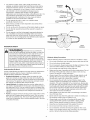 4
4
-
 5
5
-
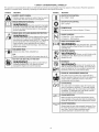 6
6
-
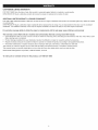 7
7
-
 8
8
-
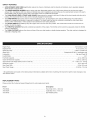 9
9
-
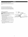 10
10
-
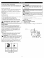 11
11
-
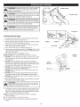 12
12
-
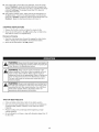 13
13
-
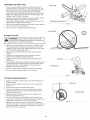 14
14
-
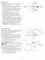 15
15
-
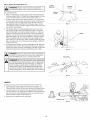 16
16
-
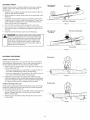 17
17
-
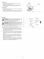 18
18
-
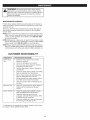 19
19
-
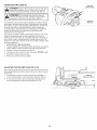 20
20
-
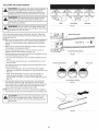 21
21
-
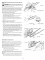 22
22
-
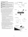 23
23
-
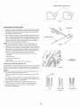 24
24
-
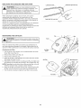 25
25
-
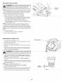 26
26
-
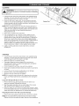 27
27
-
 28
28
-
 29
29
-
 30
30
-
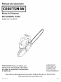 31
31
-
 32
32
-
 33
33
-
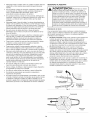 34
34
-
 35
35
-
 36
36
-
 37
37
-
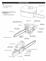 38
38
-
 39
39
-
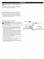 40
40
-
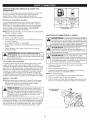 41
41
-
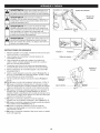 42
42
-
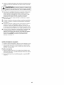 43
43
-
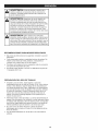 44
44
-
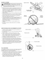 45
45
-
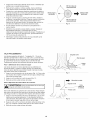 46
46
-
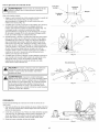 47
47
-
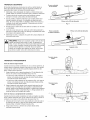 48
48
-
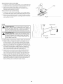 49
49
-
 50
50
-
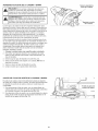 51
51
-
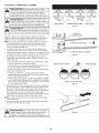 52
52
-
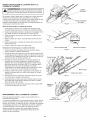 53
53
-
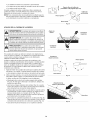 54
54
-
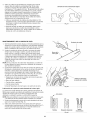 55
55
-
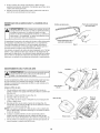 56
56
-
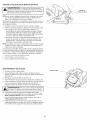 57
57
-
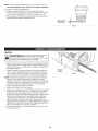 58
58
-
 59
59
-
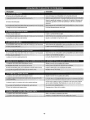 60
60
-
 61
61
-
 62
62
-
 63
63
-
 64
64


Craftsman 316.380700 Manual de usuario
- Categoría
- Motosierras eléctricas
- Tipo
- Manual de usuario
- Este manual también es adecuado para
en otros idiomas
- English: Craftsman 316.380700 User manual
Artículos relacionados
-
MTD 41AY469S799 El manual del propietario
-
Craftsman 41BY427S799 El manual del propietario
-
-
-
-
-
-
-
-